Embed Size (px)
Citation preview
370
1. IntroductIon The main parameters influencing the size and weight of the
engine are swept volume, engine layout and design parameters. For the same power output, the swept volume of the engine can be reduced by:(a) Increasing the brake mean effective pressure (BMEP)(b) Increasing the operating speed of the engine and (c) Improving the efficiency of the engine.
The means of achieving these parameters are explained in detail while considering the environment in which the engines will be exploited.
2. HIGHEr BMEPBMEP has large impact on the size of the engine for a
desired performance. Increasing the BMEP of the engine also improves the engine efficiency. This is primarily due to the fact that for a given engine, the friction power depends more on the speed of the engine and very little on the BMEP. Consequently, by increasing the BMEP of the engine, the increase in friction power is almost negligible. This results in a significant improvement in mechanical efficiency of the engine.
For example, a naturally aspirated diesel engine will have a specific fuel consumption (SFC) of around 270 g/(kW-hr). When this engine is turbocharged, i.e. the BMEP is increased, the SFC will improve to around 215 g/(kW-hr). Hence, turbo charging not only improves the engine power by increasing the charge air mass flow rate, but also increases engine power by improving the engine efficiency. One of today’s most efficient diesel engines, the Wartsila-31, achieves a magnificent SFC
value of 163 g/(kW-hr) by operating at a BMEP of nearly 30 bar. Figure 1 shows the Wartsila-31 engine.
The BMEP of the engine can be improved by (a) Increasing the charge density and (b) Reducing the operating Air/Fuel ratio.
technologies for High Power density diesel Engines
N.S. Prasad*, N. Ganesh, and A. Kumarasamy Engine Division, Combat Vehicles Research and Development Establishment, Chennai - 600 054, India
*E-mail: [email protected]
ABstrAct
The engines used in armoured fighting vehicles have to be compact, light in weight, efficient and reliable. In order to achieve a compact engine design, a complete understanding of all the factors affecting the engine performance is needed. However, it is important to note that the performance of the engine cannot be compromised in the pursuit of compactness. The aim of this paper is to classify systematically various broad areas affecting the engine’s power to weight and power to volume ratio and discuss respective current technologies available. This paper explores the possibility of size and weight reduction and efficiency enhancement of diesel engines by the use of various methods like engine friction reduction, better thermal management, high injection pressure, and turbocharging. Achieving high engine speeds and high BMEP will be the means of achieving high power density. The effects of engine configuration and technologies on compactness are also discussed. Finally, the configuration of a new engine and its design aspects, incorporating all the aforementioned concepts is discussed
Keywords: High speed engine; BMEP; AFV Engine; Compact engine
Figure 1. Wartsila 31, One of the most fuel efficient engines in the world.
2.1 charge Air densityCharge air density improvements can be achieved by
either supercharging (compressor is driven by the engine) or turbocharging (compressor driven by exhaust gases). Today, a single stage turbocharger with a centrifugal compressor can
Defence Science Journal, Vol. 67, No. 4, July 2017, pp. 370-374, DOI : 10.14429/dsj.67.11537 2017, DESIDOC
Received : 13 March 2017, Revised : 25 May 2017 Accepted : 26 May 2017, Online published : 03 July 2017
PRASAD, et al.: TECHNOlOGIES FOR HIGH POWER DENSITy DIESEl ENGINES
371
provide a charge pressure ratio of 3.5 with ease. For higher charge pressure ratios, multi-staging concepts like series turbocharging are used1.
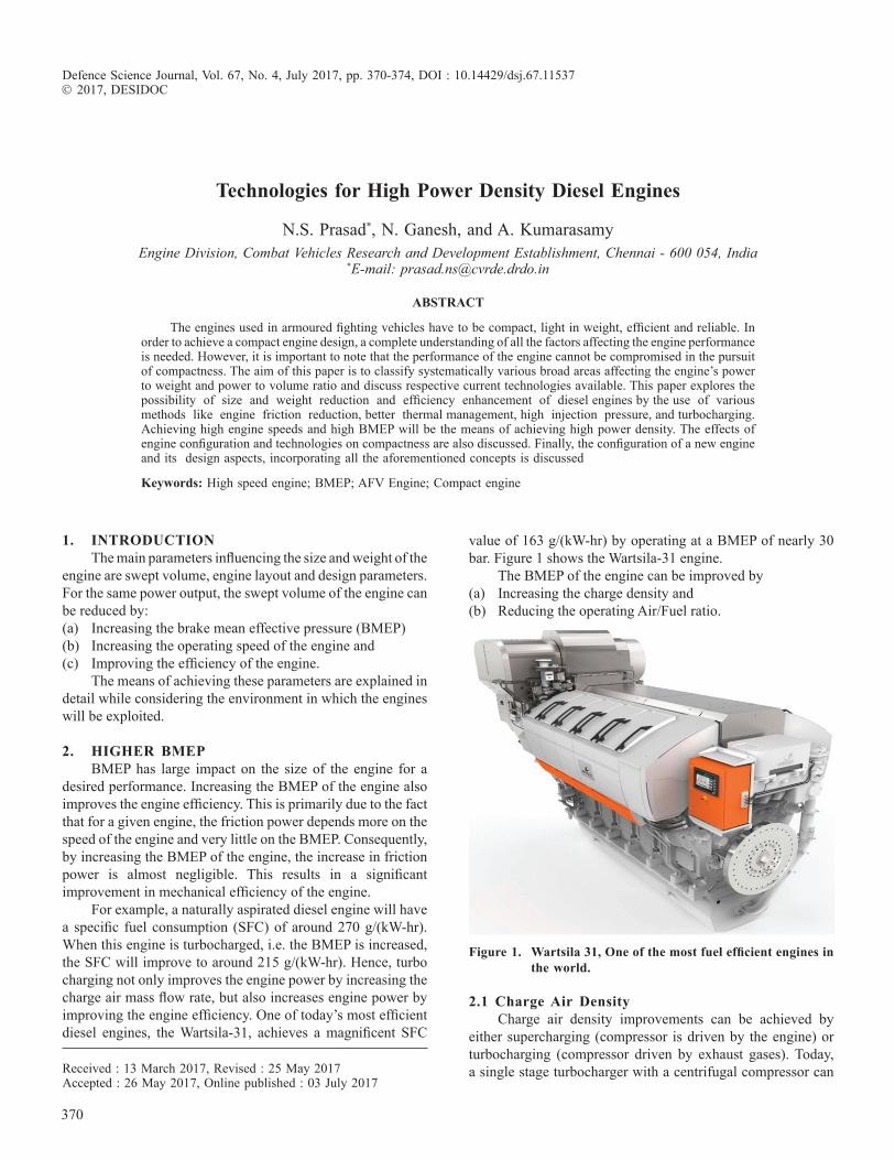
Turbo-compounding, where a power turbine (connected mechanically with the crankshaft) is used to extract energy from the exhaust gas, allows better expansion of the combustion gases and helps in improving the efficiency of the engine. Figure 2 shows a Turbo-compounded engine.
Charge air cooling increases the density of the charge. This plays a more significant role when the turbocharger pressure ratio is higher2. Typically, a heat exchanger is used to cool the air after the turbocharger, before the manifold. This heat exchanger can be either air-to-air or air-to-water. The air-to-air charge coolers have better potential. But the air-to-water charge coolers allow better packaging. Hence almost all armoured fighting vehicles (AFVs) air to water cooling.
3.1 Engine speedMean piston speed is usually taken as a limiting factor for
finalizing the engine speed. In AFV engines, higher mean piston speed is used to achieve compactness and it is in the range of 12 to 14 m/s. To further enhance specific power output, future engines will be increased upto 15 m/s by using proper coatings and improved lubricants4.
Friction reduction techniques aid in improving the engine speed. Some of the techniques are(i) Offset piston pin(ii) Special coatings on pistons(iii) Reduction in tangential force on piston rings(iv) Rolling element bearings for crankshaft and camshaft
3.2 BalancingFully balanced engine configurations are those that allow
the complete balancing of both 1st and 2nd order inertia forces and moments. The common configurations that offer full balance are a) Inline six cylinder b) 90 degree V8 with cross plane crankshaft, c) Boxer 6 cylinder and d)12 cylinder V engine. However, by the judicious use of balancer shafts, it is possible to balance most other configurations.
3.3 rate of combustionRate of combustion can be improved by the same methods
that were used in reducing the air/fuel ratio, i.e. better fuel injection pressure, higher swirl etc... At higher engine speeds, the time available for burning the fuel becomes lesser. But the chemical kinetics remain un-altered. The only change is due to the increase in turbulence due to the increase in piston & gas velocities. Hence, the rate of chemical reaction is an important bottle-neck in developing engines that operate at higher speeds5.
3.4 Inertial stresses in reciprocating componentsDesign optimisation using FEA tools along with materials
having enhanced strength allow the design of components
Figure 2. turbo-compounding.
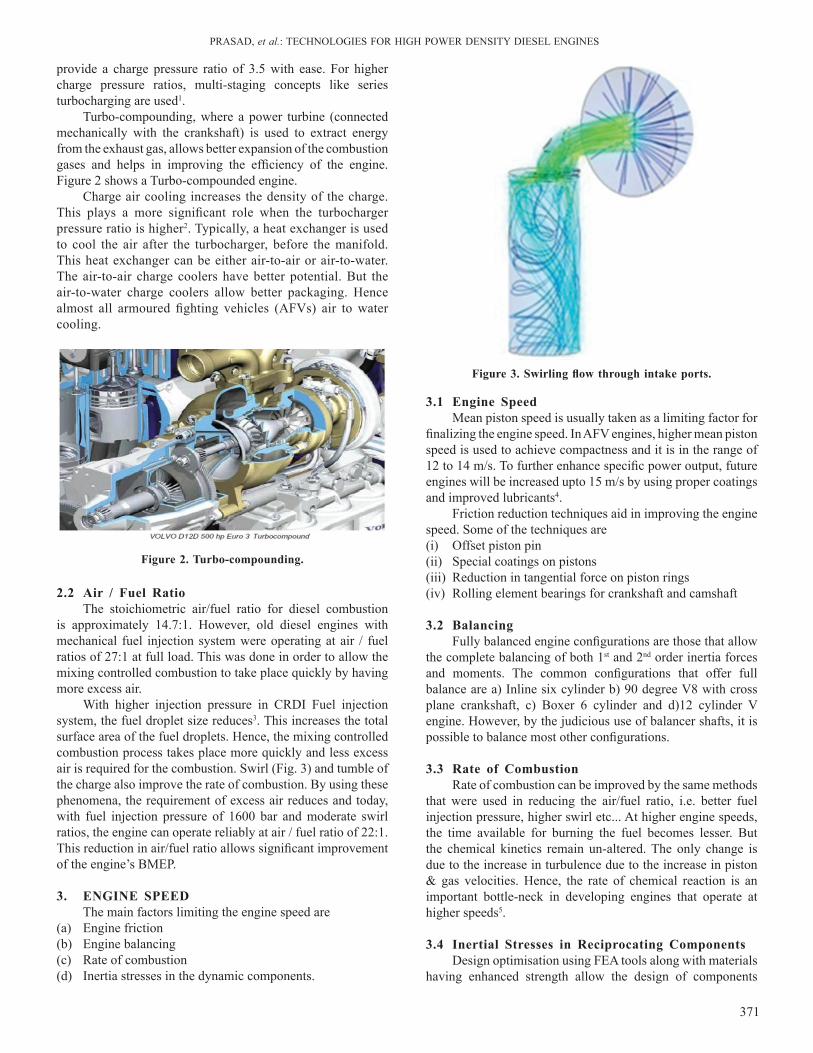
Figure 3. Swirling flow through intake ports.
2.2 Air / Fuel ratioThe stoichiometric air/fuel ratio for diesel combustion
is approximately 14.7:1. However, old diesel engines with mechanical fuel injection system were operating at air / fuel ratios of 27:1 at full load. This was done in order to allow the mixing controlled combustion to take place quickly by having more excess air.
With higher injection pressure in CRDI Fuel injection system, the fuel droplet size reduces3. This increases the total surface area of the fuel droplets. Hence, the mixing controlled combustion process takes place more quickly and less excess air is required for the combustion. Swirl (Fig. 3) and tumble of the charge also improve the rate of combustion. By using these phenomena, the requirement of excess air reduces and today, with fuel injection pressure of 1600 bar and moderate swirl ratios, the engine can operate reliably at air / fuel ratio of 22:1. This reduction in air/fuel ratio allows significant improvement of the engine’s BMEP.
3. EnGInE sPEEdThe main factors limiting the engine speed are
(a) Engine friction (b) Engine balancing (c) Rate of combustion(d) Inertia stresses in the dynamic components.
DEF. SCI. J., VOl. 67, NO. 4, July 2017
372
with lower mass. Hence, it is possible to design components to operate at higher engine speeds while keeping the stresses under control. The main components considered for such mass reduction are piston, gudgeon pin, connecting rod and crankshaft.
4. EnGInE conFIGurAtIonEngine configuration will determine the distribution of
the length, width & height of the engine. The packaging design also determines the overall volume of the engine.
4.1 Vee configurationInline engines have only one connecting rod per crank
throw. Vee engines have two connecting rods per crank throw. Hence, Vee engine are more compact than the inline engine and mostly Vee engines are used in Military engines. Figure 4 shows a typical V12 engine.
years in uK. While the OPOC engine has been demonstrated at lower power levels, it is yet to be proven for high power applications.
5. tEcHnoloGIEs to suIt EnVIronMEnt 5.1 severe dust concentration
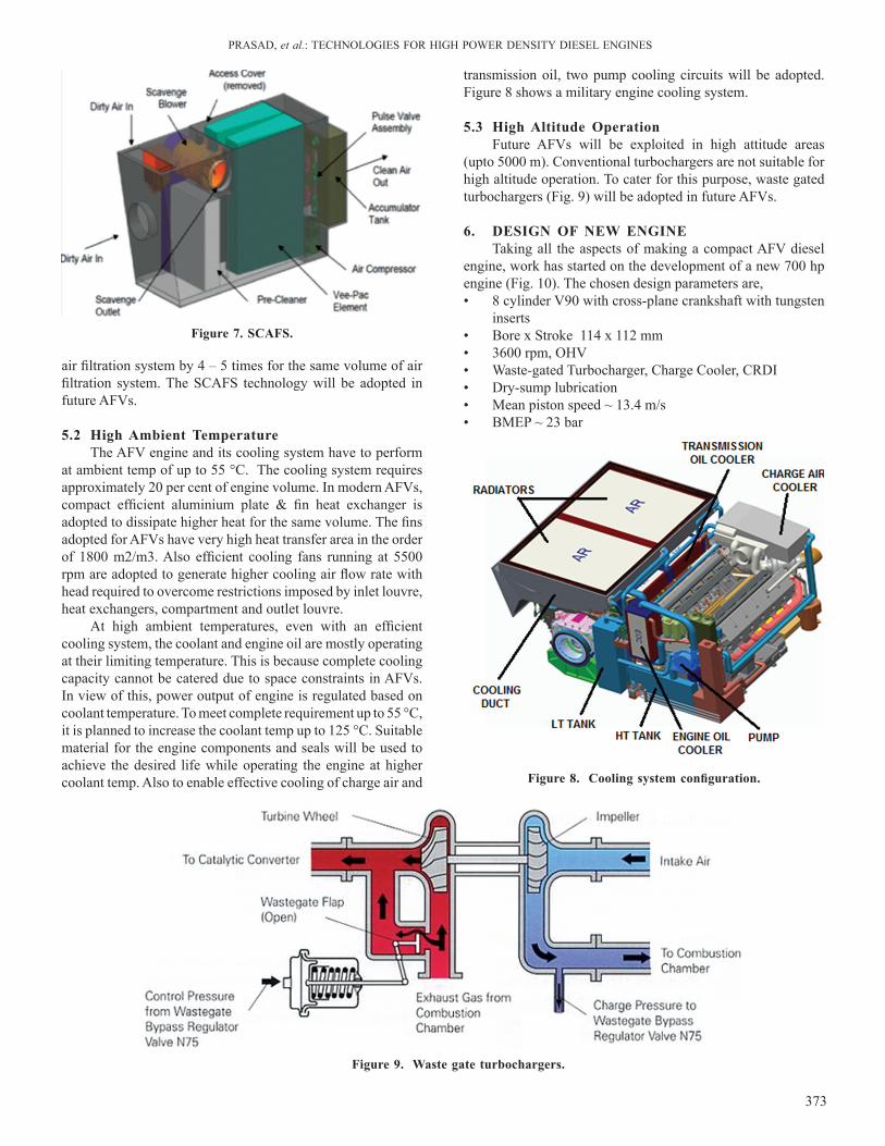
Atmospheric dust concentration in Indian desert conditions is of the order of 2g/m3. Two stage air filtration systems with positive dust extraction are used in armoured fighting vehicles (AFVs). First stage consists of cyclones which filters majority of the particles and second stage filters fine particles. Air filter occupies a volume of 15 per cent. Even with 15 per cent volume catered for the air filtration system, the two stage system offers a life of only 400 km. This requires frequent filter replacement, higher logistics requirement and interruptions to the mission.
To enhance the life of the filter element or to increase the replacement interval, Self Cleaning Air Filtration System (SCAFS) is adopted. In SCAFS (Fig. 7), the filter element is automatically cleaned online when specified pressure drop across the filter limit is reached. This enhances the life of the
Figure 4. cVrdE 1500 hp engine – 12 cyl V90°.
Figure 5. Mtu Mt890 engine.
Figure 6. Eco-motors oPoc engine.
4.2 PackagingPackaging of various sub systems like engine oil cooler,
filters... as an integral part of crankcase results in a compact and reliable engine as joints of coolant, oil and fuel lines are minimised. Figure 5 shows a well packaged engine.
4.3 Opposed Piston Two-Stroke EnginesThe Two stroke Opposed Piston configuration with uni-
flow scavenging results in a very compact and light weight engine. Due to the absence of valve train and cylinder head, the engine can be more efficient. However, the asymmetry in the design of the combustion chamber produces poor combustion characteristics. These engines allow large quantity of air to pass through the engine without participating in the combustion and expansion process. Also, by necessity, these engines operate with air fuel ratios close to 27:1
The OPOC engine (Fig. 6) by Eco-Motors, uSA has a compact arrangement. This engine is very similar to the Doxford marine opposed piston engine that was built for many
PRASAD, et al.: TECHNOlOGIES FOR HIGH POWER DENSITy DIESEl ENGINES
373
air filtration system by 4 – 5 times for the same volume of air filtration system. The SCAFS technology will be adopted in future AFVs.
5.2 High Ambient temperatureThe AFV engine and its cooling system have to perform
at ambient temp of up to 55 °C. The cooling system requires approximately 20 per cent of engine volume. In modern AFVs, compact efficient aluminium plate & fin heat exchanger is adopted to dissipate higher heat for the same volume. The fins adopted for AFVs have very high heat transfer area in the order of 1800 m2/m3. Also efficient cooling fans running at 5500 rpm are adopted to generate higher cooling air flow rate with head required to overcome restrictions imposed by inlet louvre, heat exchangers, compartment and outlet louvre.
At high ambient temperatures, even with an efficient cooling system, the coolant and engine oil are mostly operating at their limiting temperature. This is because complete cooling capacity cannot be catered due to space constraints in AFVs. In view of this, power output of engine is regulated based on coolant temperature. To meet complete requirement up to 55 °C, it is planned to increase the coolant temp up to 125 °C. Suitable material for the engine components and seals will be used to achieve the desired life while operating the engine at higher coolant temp. Also to enable effective cooling of charge air and Figure 8. Cooling system configuration.
Figure 9. Waste gate turbochargers.
Figure 7. scAFs.
transmission oil, two pump cooling circuits will be adopted. Figure 8 shows a military engine cooling system.
5.3 High Altitude operationFuture AFVs will be exploited in high attitude areas
(upto 5000 m). Conventional turbochargers are not suitable for high altitude operation. To cater for this purpose, waste gated turbochargers (Fig. 9) will be adopted in future AFVs.
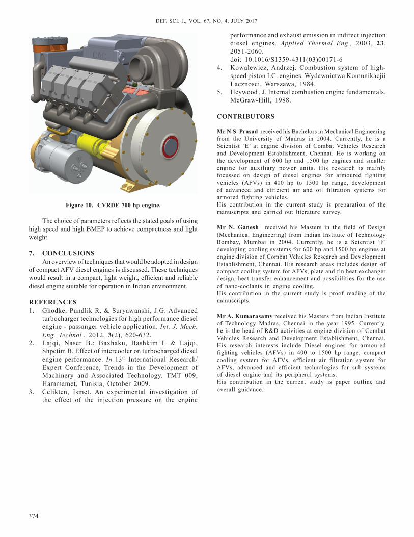
6. dEsIGn oF nEW EnGInETaking all the aspects of making a compact AFV diesel
engine, work has started on the development of a new 700 hp engine (Fig. 10). The chosen design parameters are,• 8 cylinder V90 with cross-plane crankshaft with tungsten
inserts• Bore x Stroke 114 x 112 mm• 3600 rpm, OHV• Waste-gated Turbocharger, Charge Cooler, CRDI• Dry-sump lubrication• Mean piston speed ~ 13.4 m/s• BMEP ~ 23 bar
DEF. SCI. J., VOl. 67, NO. 4, July 2017
374
The choice of parameters reflects the stated goals of using high speed and high BMEP to achieve compactness and light weight.
7. conclusIonsAn overview of techniques that would be adopted in design
of compact AFV diesel engines is discussed. These techniques would result in a compact, light weight, efficient and reliable diesel engine suitable for operation in Indian environment.
rEFErEncEs1. Ghodke, Pundlik R. & Suryawanshi, J.G. Advanced
turbocharger technologies for high performance diesel engine - passanger vehicle application. Int. J. Mech. Eng. Technol., 2012, 3(2), 620-632.
2. lajqi, Naser B.; Baxhaku, Bashkim I. & lajqi, Shpetim B. Effect of intercooler on turbocharged diesel engine performance. In 13th International Research/Expert Conference, Trends in the Development of Machinery and Associated Technology. TMT 009, Hammamet, Tunisia, October 2009.
3. Celikten, Ismet. An experimental investigation of the effect of the injection pressure on the engine
performance and exhaust emission in indirect injection diesel engines. Applied Thermal Eng., 2003, 23, 2051-2060.
doi: 10.1016/S1359-4311(03)00171-64. Kowalewicz, Andrzej. Combustion system of high-
speed piston I.C. engines. Wydawnictwa Komunikacjii lacznosci, Warszawa, 1984.
5. Heywood , J. Internal combustion engine fundamentals. McGraw-Hill, 1988.
contrIButors
Mr n.s. Prasad received his Bachelors in Mechanical Engineering from the university of Madras in 2004. Currently, he is a Scientist ‘E’ at engine division of Combat Vehicles Research and Development Establishment, Chennai. He is working on the development of 600 hp and 1500 hp engines and smaller engine for auxiliary power units. His research is mainly focussed on design of diesel engines for armoured fighting vehicles (AFVs) in 400 hp to 1500 hp range, development of advanced and efficient air and oil filtration systems for armored fighting vehicles. His contribution in the current study is preparation of the manuscripts and carried out literature survey.
Mr n. Ganesh received his Masters in the field of Design (Mechanical Engineering) from Indian Institute of Technology Bombay, Mumbai in 2004. Currently, he is a Scientist ‘F’ developing cooling systems for 600 hp and 1500 hp engines at engine division of Combat Vehicles Research and Development Establishment, Chennai. His research areas includes design of compact cooling system for AFVs, plate and fin heat exchanger design, heat transfer enhancement and possibilities for the use of nano-coolants in engine cooling.His contribution in the current study is proof reading of the manuscripts.
Mr A. Kumarasamy received his Masters from Indian Institute of Technology Madras, Chennai in the year 1995. Currently, he is the head of R&D activities at engine division of Combat Vehicles Research and Development Establishment, Chennai. His research interests include Diesel engines for armoured fighting vehicles (AFVs) in 400 to 1500 hp range, compact cooling system for AFVs, efficient air filtration system for AFVs, advanced and efficient technologies for sub systems of diesel engine and its peripheral systems.His contribution in the current study is paper outline and overall guidance.
Figure 10. cVrdE 700 hp engine.