Embed Size (px)
Citation preview

June 2011
Prepared by:
Conestoga-Rovers & Associates3851 Shell Road, Suite 110Richmond, British ColumbiaV6X 2W2
Technologies and Best Management Practices for Reducing GHG Emissions from Landfills Guidelines
British ColumbiaMinistry of Environment

Technologies and Best Management Practices for reducing GHG Emissions from landfills
Guidelines
Prepared pursuant to Section 8 (2) of the Landfill Gas Management Regulation
Approved: ________David Ranson______________________ September, 2011 Director of Environmental Standards Branch Date

056417 (5) i CONESTOGA-ROVERS & ASSOCIATES
TABLE OF CONTENTS Page
1.0 INTRODUCTION ...................................................................................................................1 1.1 GUIDELINE BOUNDARIES..............................................................................1 1.2 HOW TO USE BMP DECISION TOOL............................................................2
2.0 TECHNOLOGIES AND BEST MANAGEMENT PRACTICES........................................5 2.1 DIVERSION OF ORGANIC WASTE................................................................5 2.1.1 BMP 1A - COMPOST ..........................................................................................5 2.1.2 BMP 1B - ANAEROBIC DIGESTION...............................................................8 2.2 BMP 2 – USE OF ALTERNATIVE DAILY COVER ......................................10 2.2.1 BMP 2A - REUSABLE TARP DEPLOYMENT SYSTEM..............................11 2.2.2 BMP 2B - BIODEGRADABLE TARP DEPLOYMENT SYSTEM.................13 2.2.3 BMP 2C - STEEL PLATES ................................................................................15 2.3 BMP 3 - USE OF ALTERNATIVE INTERMEDIATE/FINAL COVER......17 2.3.1 BMP 3A - BIOCOVER.......................................................................................18 2.3.2 BMP 3B - EVAPOTRANSPIRATION COVER ..............................................21 2.3.3 BMP 3C - GEOMEMBRANE............................................................................23 2.3.4 BMP 3D - SOLAR GEOMEMBRANE.............................................................24 2.3.5 BMP 3E - BIOFILTER ........................................................................................26 2.3.6 BMP 3F - INCREASE COVER THICKNESS..................................................28 2.4 BMP 4 - REDUCING SURFACE AREA OF EXPOSED TIPPING FACE...29 2.5 BMP 5 - LANDFILL GAS COLLECTION BMPS ..........................................31 2.5.1 BMP 5A - INCREASE COLLECTION WELL/TRENCH DENSITY ..........31 2.5.2 BMP 5B - EARLY INSTALLATION OF LFG COLLECTION SYSTEM.....33 2.5.3 BMP 5C - LFG UTILIZATION.........................................................................36 2.5.4 BMP 5D - INSTALLATION OF LFG COLLECTION SYSTEM...................39 2.6 BMP 6 - USE OF BIOREACTOR LANDFILL DESIGNS ..............................40 2.6.1 BMP 6A - ANAEROBIC BIOREACTOR ........................................................41 2.6.2 BMP 6B - AEROBIC BIOREACTOR ...............................................................43 2.6.3 BMP 6C - BIOCELL/FACULTATIVE BIOREACTOR .................................46 2.7 BMP 7 - SURFACE EMISSIONS PREVENTION...........................................48 2.8 BMP 8 - RETROFIT ANAEROBIC BIOREACTOR LANDFILL..................50 2.9 BMP 9 – CONSTRUCT DEEPER LANDFILLS..............................................53
3.0 ADDITIONAL SOURCES OF INFORMATION...............................................................55

056417 (5) ii CONESTOGA-ROVERS & ASSOCIATES
LIST OF FIGURES FIGURE 1 BMP DECISION TOOL
LIST OF TABLES TABLE 2.1 LFG COLLECTION SYSTEM INSTALLATION SCHEDULE TABLE 2.2 POTENTIAL REVENUE FROM SELLING CARBON CREDITS
056417 (5) iii CONESTOGA-ROVERS & ASSOCIATES
ACKNOWLEDGEMENTS
This Guidelines Document has been prepared by Conestoga-Rovers & Associates (CRA) on behalf of the British Columbia Ministry of Environment (MOE) to support the MOE in the implementation of the Landfill Gas Management Regulation (BC MOE, 2008), and specifically in the development of best management practices and technologies for reducing greenhouse gas emissions from landfills. Natalia Kukleva, Frank Rhebergen, Rob Dalrymple, Jack Bryden, and Allan Leuschen of the MOE provided insight and support in selecting the technologies and best management practices for reducing greenhouse gas emissions from landfills that have been included in this report and interpreting the Landfill Gas Management Regulation throughout this process.

056417 (5) iv CONESTOGA-ROVERS & ASSOCIATES
ACRONYMS AND ABBREVIATIONS BMP best management practice
cfm cubic feet per minute
CH4 methane
cm/s centimetre per second
CRA Conestoga-Rovers & Associates
ET evapotranspiration
FID flame ionization detector
GHG greenhouse gas
Guidance Document Technologies and Best Management Practices for Reducing GHG Emissions from Landfills, Guidance Document
km kilometre
kWh kilowatt hour
L litre
L&YM leaf and yard material
LFG landfill gas
m metre
m2 square metre
m3 cubic metre
mm millimetre
MOE British Columbia Ministry of Environment
MSW municipal solid waste
MW megawatt
ppm parts per million
O&M operation and maintenance
Regulation British Columbia Landfill Gas Management Regulation, Order in Council No. 903, Ordered and Approved December 8, 2008
SCADA supervisory control and data acquisition systems
SSO source-separated organic
USEPA United States Environmental Protection Agency

056417 (5) v CONESTOGA-ROVERS & ASSOCIATES
PREFACE This Technologies and Best Management Practices for Reducing GHG Emissions from Landfills Guidance Document (Guidance Document) has been developed for the British Columbia (BC) Ministry of Environment (MOE) to provide guidance for the selection of technologies and best management practices (BMPs) for reducing greenhouse gas (GHG) emissions from municipal solid waste (MSW) landfills in BC. The technologies and BMPs discussed in this Guideline have been designed to complement the MOE's Landfill Gas Management Facility Design Guidelines and Landfill Gas Management Regulation (Regulation). The optimal approach for reducing GHG emissions from landfills is to develop a well-designed, operated, and maintained landfill gas (LFG) collection system. The intent of the recommended BMPs is not to supplement a poorly performing LFG collection system, but to be used in addition to a well performing system or to be utilized at sites where LFG collection is currently not present. This Guideline is based on technical experience in the field of MSW landfill design and LFG management facilities design and best practices for GHG emissions management. The intent of this document is to provide guidance for the selection of BMPs that address the reduction of GHG emissions in addition to other ancillary benefits that may result from their implementation. However, information on the design, installation, and operation of each BMP is not within the scope of this Guideline. Additional information such as applicable site conditions, cost considerations, feasibility, and supplemental benefits of the BMPs are discussed in this document to provide further selection criteria for the user. It is strongly recommended that an in-depth consideration of applicable BMPs be undertaken by landfill owners/operators to specifically determine the potential benefits of a given approach or technology, and to estimate viability on a site-specific basis. As LFG management is a distinctly site-specific issue, the intention of this document is not to prescribe in detail the BMPs for every possible set of landfill configurations and conditions. However, this document does prescribe site condition recommendations for which the BMPs may apply. Note that this document acknowledges the challenges of reducing GHG emissions using the BMPs, and an assessment should be conducted to ensure that a selected BMP is feasible for site-specific conditions. Correctly utilized and applied, the BMPs noted in this document will serve to provide additional GHG emission reductions benefits as well as ancillary benefits without compromising effective landfill operations.
056417 (5) vi CONESTOGA-ROVERS & ASSOCIATES
To achieve the greatest reduction of GHG emissions as specified within this Guideline, it is expected that owners and operators will need to treat the landfill as a living organism; all systems related to the operations of the landfill must be integrated and treated as one complex system when implementing GHG emission reduction BMPs.
056417 (5) 1 CONESTOGA-ROVERS & ASSOCIATES
1.0 INTRODUCTION
This Guidance Document is intended to be used by landfill owners, operators, and qualified professionals. It provides the user with guidance on the selection of site-specific BMPs for landfills in BC. This Guideline has been organized into the following sections: Section 1.0 Provides an introduction to this Guideline, describes the boundaries of
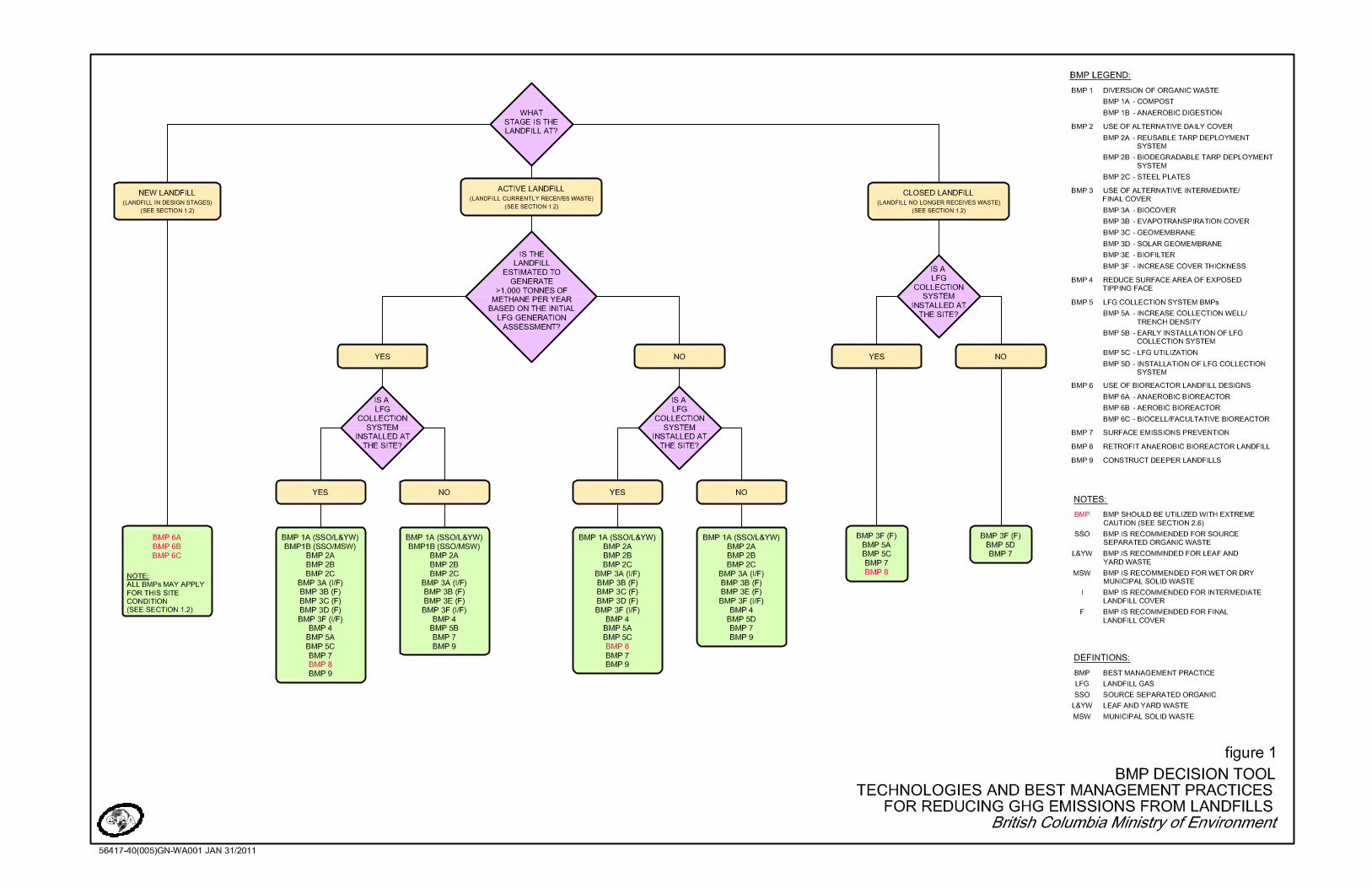
the Guideline, and provides a description on how to properly use the BMP Decision Tool (Figure 1)
Section 2.0 Provides a description of all the BMPs, including their GHG emission reduction potential, and additional considerations
Section 3.0 Provides additional sources of information the users may investigate to learn more about the subject of reducing GHG emissions from landfills
This document is intended to present BMPs as it relates to the reduction of GHG emissions from landfill sites in BC. It provides a description of site condition applicability, potential GHG emission reductions, cost considerations, feasibility, and supplemental benefits, with the expectation that such guidance is applicable to the vast majority of landfills in BC. It is recognized and understood that the BMPs presented in this document must be developed and utilized using site-specific information and considerations. 1.1 GUIDELINE BOUNDARIES
For this Guideline, only BMPs that reduce GHG emissions within the boundaries of the landfill site were considered, although there are BMPs that reduce GHG emissions from off-site operations (e.g., reducing GHG emissions from material transportation). While the boundaries relate to the landfill itself, it is important to understand and consider a more holistic approach that would include life cycle considerations. These items would further identify the upstream and downstream potential GHG factors behind a given BMP. For example, the GHG emissions associated with the manufacturing of a material to be utilized for a BMP may be comparable to the potential GHG emission reductions that the BMP will provide at the landfill site. As well, the process of disposing of materials used for a BMP after they have been utilized may also be important. The cradle-to-grave
056417 (5) 2 CONESTOGA-ROVERS & ASSOCIATES
aspect of GHG emissions are often neglected in GHG evaluation, and in the spirit of the MOE's objective of reducing GHG emissions in the province of BC, users of this Guideline are encouraged to consider the associated upstream and downstream impacts of the BMPs as they relate to the baseline or current condition. The one exception to the above-mentioned boundaries is the utilization of LFG (BMP 5C), which alone does not reduce GHG emissions from the landfill site. However, utilization does off-set dirtier forms of energy generation in BC, which are comprised of local generation and imported electricity from Alberta and the United States. Since this BMP provides real GHG emission reductions for the province and is a highly beneficial landfill practice, it has been included in these Guidelines. 1.2 HOW TO USE BMP DECISION TOOL
Presented on Figure 1 is the BMP Decision Tool, which consists of a decision tree framework designed to provide easy to understand recommendations and criteria for determining a set of BMPs that would be most suitable and feasible for reducing LFG emissions at a particular site in BC. The BMP Decision Tool uses the following site conditions criteria to guide users to a select list of BMPs that are best suited for their landfill site conditions: Landfill Stage
New: Refers to sites that are in the design stage. This may refer to new cells at existing landfills.
Active: Refers to sites that are currently accepting waste and have yet to undergo full closure, as well as sites that are transitioning towards closure.
Closed: Refers to sites that have ceased to accept any waste and have undergone full closure of the landfill.
Estimated LFG Generation
Yes: Landfill site is currently estimated to generate greater than 1,000 tonnes of methane per year, based on the Initial LFG Generation Assessment.
No: Landfill site is currently estimated to generate less than 1,000 tonnes of methane per year, based on the Initial LFG Generation Assessment; or has not completed a LFG Generation Assessment as per the Regulation.

056417 (5) 3 CONESTOGA-ROVERS & ASSOCIATES
LFG Collection System
Yes: A LFG collection system is currently installed at the landfill site.
No: A LFG collection system is not currently installed at the landfill site. Of note, landfills transitioning to closure in the short term are best represented by the active landfill classification, but all BMPs under the closed landfill classification do apply. Additional site-specific conditions, such as climate, waste composition, annual precipitation, and temperature are discussed in the document as they apply to the specific BMP. While these factors certainly have an influence on the selection of BMPs, users of this document are encouraged to explore a wide range of BMPs that may be applicable to their sites. It should be recognized that the noted factors will affect the viability of BMPs in some cases, and thus the requirement to perform site-specific analysis of the applicability of a BMP is critical. The BMP Decision Tool proposes site-specific questions based on the site conditions criteria to characterize the user's landfill site into a group of applicable BMPs. Once the user has determined which site conditions apply, a recommended list of BMPs is provided, each of which are able to reduce GHG emissions from the landfill. The user can then consult with this Guideline document for the following detailed information on each of the BMPs recommended for their site: Description: Brief explanation of the BMP and how it is typically implemented.
Site Condition Applicability: Description of the recommended site conditions (e.g., landfill stage, estimated LFG generation, LFG collection system) that the BMP should ideally be implemented under.
GHG Emission Reductions Benefits: Description of how the BMP will be able to reduce GHG emissions from the landfill site. Of note, some technologies lend themselves to a relatively simple estimation of potential GHG emission reductions, while others have a large and demonstrable emission reductions benefits. However, other technologies have obvious but less quantifiable emission reductions benefits. Users of this document are encouraged to note that many of the BMPs described are implemented for reasons other than GHG reductions, and thus the ability to quantify GHG emission reductions is not complemented with specific protocols and procedures at this point.
Cost Considerations: Cost factors to consider when implementing the BMP (e.g., capital costs, energy generation revenue, etc.). Cost information for BMPs is
056417 (5) 4 CONESTOGA-ROVERS & ASSOCIATES
highly site and condition-specific, and the users of this document are strongly encouraged to take cost data into consideration purely for conceptual/estimative purposes. Actual costs should be investigated pending required design and procurement activities. In some cases, cost data for some of the BMPs is not readily available.
Feasibility: An evaluation of the BMP's anticipated performance and its ability to be effectively implemented.
Supplemental Benefits: Description of additional benefits, other than GHG emission reductions, that the BMP may provide. Of note, in many cases, a BMP may be enacted for a reason wholly disparate from the goal of GHG reduction, but may have an obvious GHG benefit. This document will provide some guidance for users, therefore, on potential GHG benefits of initiatives and programs already in placed.
This information is intended to inform and provide a basis for further investigation of the specific applicability of BMPs at a given site. As a general cautionary note, several BMPs are mentioned that require significant upgrades to landfill systems and a high level of attention to operational control for successful implementation. For new landfills, consideration has been made for bioreactor-type landfills, but even for designed landfills, care must be exercised in implementing such technologies, as they require specific design expertise and management of all landfill systems. For existing landfills, implementation of bioreactor features has been noted as cautionary, as these features will have a significant effect on the overall system, and may result in negative consequences on those systems if not implemented with caution.
056417 (5) 5 CONESTOGA-ROVERS & ASSOCIATES
2.0 TECHNOLOGIES AND BEST MANAGEMENT PRACTICES
2.1 DIVERSION OF ORGANIC WASTE
The source of GHG emissions from landfills is the organic waste content (i.e., leaf and yard material [L&YM], food waste, wood waste, paper, etc.) that undergoes anaerobic decomposition inside the oxygen-depleted landfill and produces LFG. These BMPs propose diverting source-separated organic (SSO) materials away from the landfill, thus preventing generation of LFG. 2.1.1 BMP 1A - COMPOST
Description
This BMP is achieved by diverting organic wastes which are regularly deposited within the landfill, to an on-site composting operation, where it is degraded through aerobic conditions (i.e., windrow piles or in-vessel technology). This technology is generally restricted to organics streams that have been separated at the source. For L&YM systems, composting typically is in the form of open windrow composting on an outdoor pad; for SSO characterized by food waste, composting can be undertaken in a variety of systems depending on location, volumes, and the character of the waste, up to and including fully enclosed in-vessel systems with sophisticated process control systems.
Of note, it is recommended that landfill owners refer to the MOE's Organic Matter Recycling Regulation, which governs the production, quality, and land application of certain types of organic matter, including compost (BC MOE, 2002). Site Condition Applicability
On-site composting is generally applicable to active landfills that currently receive organic materials separated at its source, as the separation of the organic stream at the landfill site is typically not feasible. If source separation (such as green bin collection of organics or separate collection of L&YM) is not yet implemented, the resources required to implement such techniques should be taken into account when investigating this option, as such separation techniques are generally cost and resource-intensive. For landfills where well-designed and well-operated LFG collection and destruction systems are in operation, diversion of organics proportionately does little to mitigate further emissions, although there are a number of ancillary benefits, such as the saving

056417 (5) 6 CONESTOGA-ROVERS & ASSOCIATES
to landfill airspace for other materials. This technology is also typically feasible for larger individual sites or regional consolidated sites only, where a large volume of SSO waste is received daily; for example, sophisticated in-vessel systems are generally feasible above 10,000 tonnes per year volume. GHG Emission Reduction Benefits
Aerobic decomposition from well-managed composting will result in only the emission of carbon dioxide and water vapour, although the carbon dioxide fraction is considered to be biogenic and does not add a net GHG load from the site (USCC, 2010). Due to the heterogeneous nature of a compost pile, some methane may form in anaerobic pockets within the pile, and thus the actual GHG reduction is a direct function of the ability of the technology to aerate appropriately. GHG offsets from the process of aerobic composting may be estimated using one of the following protocols: United Nations Framework Convention on Climate Change (UNFCCC) -
Avoidance of Methane Emissions from Composting Protocol
Climate Action Reserve (CAR) - Organic Waste Composting Project Protocol
Alberta Environment - Compost Quantification Protocol
Calculation of the emission reductions from composting operations proceeds according to the above protocols where GHG credits are being applied for. A more generalized variation of these approaches can be utilized for GHG emission reductions estimation purposes, as required. The total amount of potential emission reductions must always be evaluated against the baseline scenario. For situations where it can be viably estimated that a high fraction of LFG generated in the landfill setting would already be captured, the opportunity for incremental emission reductions decreases. Generally, the total amount of emission reductions is on the order of 1 tonne of carbon dioxide equivalent reduction for every tonne of organic material that is diverted; however, an assessment must be undertaken on a specific basis taking into account the baseline condition, the nature of the feedstock, and the requirements of a specific protocol. Cost Considerations
The costs associated with implementing an on-site composting facility vary significantly with the method of composting due to the type of infrastructure that is required to perform the operation, which would be determined primarily by the volume and quality of SSO material available. High volumes of food wastes are generally best addressed
056417 (5) 7 CONESTOGA-ROVERS & ASSOCIATES
using enclosed composting operations where capital and operating costs are high, on the order of $100 per tonne or higher. Relatively small L&YM composting sites, meanwhile, can be appropriately and successfully undertaken outdoors on pads in a windrow configuration at a fraction of that cost. The costs for the actual separation systems, such as provision of green bins and separate pick-up and transportation of materials, are additional cost items. A typical windrow composting facility requires a low permeability storage pad and windrow pile turning equipment for basic composting operations, but the regulatory outlook must be understood and outdoor operations that include organic food wastes tend to have potential for localized odour issues. Capital and operating costs for composting SSO material are generally in excess of typical landfill tip fees; equivalent costs for L&YM, generally undertaken in open windrow configuration, are usually lower and are often already incorporated into existing waste management systems. In reality, landfill tip fees are a strong predictive price of the viability of organic food waste composting. Feasibility
On-site composting is generally feasible where source separation of organics is achieved at the residential level. The practice is relatively costly and there are generally drivers to implement this BMP that are beyond the goal of reducing GHG emissions, such as preserving landfill airspace. Feasibility of food-grade composting may additionally improve if access to landfill becomes limited, and as tip fees increase; however, L&YM programs are simple to implement and manage, and are generally common. For more complex materials such as SSO waste, GHG emissions are seldom the primary driver, and this BMP is unlikely to be implemented unless such a program is already envisioned for other reasons. The availability of land at the landfill site to host the composting pad or facility is required for implementing this technology. Weather and climate may play a factor for outdoor composting operations, as an all-weather surface is necessary unless the operation is going to be seasonal. Access to water for process operations is another important requirement. Supplemental Benefits
The diversion of organic waste from the landfill to composting operations will save landfill airspace, which will increase the lifespan of the landfill. The airspace savings will also provide cost savings as more waste will be able to be accepted within the lifespan of the landfill site. Additional revenue may be obtained by selling the finished

056417 (5) 8 CONESTOGA-ROVERS & ASSOCIATES
compost generated by the composting operations; however, retail cost per tonne of compost is subject to quality of the compost and available market opportunities. 2.1.2 BMP 1B - ANAEROBIC DIGESTION
Description
This BMP is achieved by diverting SSO waste regularly placed within the landfill to an on-site anaerobic digester where it may be processed to produce biogas (approximately 50 to 65 percent methane, 35 to 50 percent carbon dioxide), which may be collected and utilized for energy generation. The collected biogas is typically combusted to produce heat and electricity, thus converting its methane component to carbon dioxide, which is considered to have a global warming potential 21 times less than that of methane (over a 100 year time horizon). Anaerobic digestion is an optimal technology for managing "dirty" SSO streams, and potentially for mixed waste streams. The diverted organic waste is sent to a pre-processing system that is often characterized by light and heavy material removal for the production of a pulped fluid that contains the organic fraction of the incoming waste. Subsequently, an in-vessel digester anaerobically decomposes the pulped material, producing biogas and digested solids. The biogas can be captured and used as an alternative energy source, and the digested solids can be utilized for land application purposes or alternative landfill cover material. Of note, it is recommended that landfill owners refer to the MOE's Organic Matter Recycling Regulation, which governs the production, quality, and land application of certain types of organic matter (BC MOE, 2002) and the MOE's On-farm Anaerobic Digestions Waste Discharge Authorization Guideline, which assists anaerobic digestion facilities in applying for a waste discharge authorization under the Environment Management Act and Waste Discharge Operation (BC MOE, 2010b). Site Condition Applicability
On-site anaerobic digestion is only applicable to active landfills that currently receive organic materials separated at the source; however, MSW may be applicable for some digestion operations if the correct pre-processing equipment is utilized. Anaerobic digestion is recommended for larger sites where the diversion of significant quantities of organic wastes can justify the capital and operating expenditures of a purpose-built plant; generally, the technology is feasible if there is in excess of at least 30,000 tonnes of food wastes per year that are already separated at the source. Overall feasibility may shift if the energy sales price for biogas-related energy products increases over time.

056417 (5) 9 CONESTOGA-ROVERS & ASSOCIATES
For landfills where well-designed and well-operated LFG collection and destruction systems exist, diversion of organics proportionately does little to mitigate further emissions, although there are a number of ancillary benefits, such as the saving to landfill airspace for other materials. GHG Emission Reduction Benefits
The direct combustion of the methane component of LFG, typically through utilization, will result in the reduced global warming potential of the LFG. This factor is essentially equal for all LFG utilization systems that include combustion, and is generally the primary GHG emission reductions for this technology. Of note, the actual GHG emission reduction decreases where it can be viably indicated that the baseline landfill to which the organics would have been sent has a reasonable LFG collection system. A secondary GHG reduction for anaerobic digestion is the offset of dirtier forms of energy generation, whose value varies widely with the type of utilization system. For example, offsetting electricity in BC provides a relatively low number of emission reductions given the predominance of hydroelectric power in the province. In BC, the electrical offset emission reductions from a LFG-to-electricity project are roughly in the range of 5 to 10 percent of the total methane-related emission reductions (CRA, 2010). Additional consideration should be included for out-of-province imported electricity from Alberta and the United States, which may originate from GHG-intensive forms of electricity generation. Cost Considerations
Anaerobic digestion is a highly sophisticated process and involves a number of price points for residuals management and up-front contaminant removal. On a per-tonne basis, the all-in costs for this technology are in excess to those of composting. Considerable variation exists in the type of utilization projects, and the cost basis is generally best understood for projects that are already implemented. For example, a reciprocating engine plant generally costs between 2.5 and 3.0 million dollars per megawatt (MW) installed. Costs may be supplemented by the sale of carbon credits or energy (e.g., electricity, pipeline grade gas, vehicle fuel). Cost savings may be realized by the sale of the energy produced from a utilization system, if applicable. The purchase price under the BC Hydro Standing Offer varies by region and is between 7.3 and 8.7 cents per kWh including green attributes (carbon credits) (BC Hydro, 2009). It is expected that the price point for energy sales would have to be very high to fully support the cost of an anaerobic digestion system, which also includes cost of residuals (digested solids and

056417 (5) 10 CONESTOGA-ROVERS & ASSOCIATES
residual waste) management. Cost avoidance, such as consideration for recovered landfill airspace from the diversion activity, would need to be evaluated to justify the activity purely on the basis of cost. Feasibility
On-site anaerobic digestion is generally feasible where source separation of organics is achieved at the residential level. The practice is costly and there are generally drivers to implement this BMP that are beyond the goal of reducing GHG emissions, such as energy generation. Unlike composting, L&YM is not a recommended stream for anaerobic digestion as it is not readily degradable in a controlled digestion setting. Anaerobic digestion facilities require a sufficient amount of SSO waste on a routine basis to support the operation of the energy generation systems, as the digester system must be continuously fed. The site must receive an appropriate amount of SSO materials on a regular basis to be feasible. Available land space is another constraint. Although anaerobic digestion takes less space than a composting plant, there is ample evidence of anaerobic digestion facilities of capacity in excess of 50,000 tonnes per year that occupy on the order of a hectare of land. It should be noted, however, that the digested solids produced by an anaerobic digester may still require additional processing and need to be sent to a local or off-site composting operation. Generally, this technology should only be pursued if there is a significant premium on available landfill space and sufficient drivers to engage in a large and relatively complex project. Supplemental Benefits
The diversion of organic waste to anaerobic digestion operations liberates landfill airspace, which will increase the lifespan of the landfill. Additional revenue may be obtained by selling the energy generated from utilization operations, but the overall importance of this revenue stream must be balanced against available energy pricing and the overall capital and operating costs of the facilities. 2.2 BMP 2 – USE OF ALTERNATIVE DAILY COVER
Daily landfill cover is typically used to cover recently deposited waste to control overnight or short-term litter blowing, site odours, vector issues, promote runoff and reduce infiltration of rainfall, and reduce GHG emissions. Prior to continuing the placement of refuse each day, the conventional daily cover (e.g., soil) should typically be

056417 (5) 11 CONESTOGA-ROVERS & ASSOCIATES
scraped off the surface of the waste as a BMP to optimize landfill volume (CRA, 2010), which causes disturbances in the waste allowing for the potential escape of GHG emissions. These BMPs propose using alternative daily cover materials that would minimize disturbances to the waste and reduce potential GHG emissions from the landfill surface. 2.2.1 BMP 2A - REUSABLE TARP DEPLOYMENT SYSTEM
Description
This BMP is achieved by deploying a reusable tarp, typically made of a thin plastic material, over the working face of the exposed waste at the end of each day and then removing the tarp the following day through the use of equipment with retractable rollers. The tarp material provides similar engineering control as conventional daily covers (e.g., soil) and is removed with ease using existing landfill equipment without causing any disturbances to the working face of the waste, thus minimizing any potential releases of GHG emissions (Mercer Motor Works, 2010). The system typically consists of two components: a synthetic tarp (e.g., polypropylene, polyvinyl chloride, or polyethylene material) (Hilger et al., 2009) and the "landfill rover" machine that attaches to the blade of existing equipment (e.g., bulldozer). The landfill rover dispenses the reusable film from a roll, and ballast soil is used to keep the tarp in place. The rover is retractable and is used to remove the tarp when new waste is ready to be deposited (Robinson et al., 1998); other tarp deployment options are available, but the general principal is similar. Site Condition Applicability
The reusable tarp daily landfill cover system is generally applicable for any active landfill site that frequently receives waste that requires daily or short-term coverage. The synthetic material is able to function in cold weather environments and can be continually used throughout the year (Robinson et al., 1998). GHG Emission Reduction Benefits
The synthetic reusable tarp cover system is able to minimize GHG emissions by providing a seal over the exposed refuse, thus reducing any potential releases of GHG emissions. This particular effect, however, is difficult to quantify and cannot with certainty be quantified as having an appreciable benefit from a GHG standpoint over the use of conventional daily cover soil materials. The synthetic material used to construct
056417 (5) 12 CONESTOGA-ROVERS & ASSOCIATES
the reusable tarps is able to impede the infiltration of rainfall and reduce the amount of leachate generated within the waste, presumably to a greater extent than conventional daily cover. Control of liquid addition to the landfill waste will have an effect on both LFG generation (generally increases with additional moisture) and LFG recovery (high leachate levels can impede collection) where a LFG system is in place. However, the overall effect of a synthetic tarp system on GHG emission reductions is expected to be subtle. Cost Considerations
The costs associated with implementing the reusable tarp system vary depending on the manufacturer; however, the technology can provide significant cost savings via preservation of landfill airspace for sites where daily cover is not typically removed. Reusable synthetic daily tarps can range from $1.30 to $2.70 per square metre (m2) to cover the waste at a site (Dunson, 1997). Soil daily cover can account for as much as 10 to 15 percent of the total landfill volume when the site is full (Duffy, 2010). Site labour costs may also be reduced since the reusable tarp system is designed for quick outlay and retraction; one reference suggests that approximately 830 m2 of tarp can be laid in less than 10 minutes (Mercer Motor Works, 2010). Feasibility
The reusable synthetic tarp technology has been implemented at many landfills across Canada and BC and is generally applicable to any open site, as the reusable tarp system attaches to existing site equipment common to most landfills (e.g., bulldozer) to allow for easy deployment and retracting of the tarp material. The tarps are heavy duty and are feasible for all types of climates and site conditions. Supplemental Benefits
The main benefit from utilizing the reusable tarp system as a daily cover is the airspace savings from eliminating the use of conventional cover materials (e.g., soil) and allowing for cover to be retracted, which in turn extends the life of the landfill. In reality, while daily cover is often applied at landfills, it may not always be scraped from active tipping surfaces, unlike the retractable synthetic tarp system, which is reused daily. The tarp eliminates the potential for layers to develop within the landfill that could impede the movement of liquids and gas, and that may result in perched leachate conditions or impede the performance of active gas collection systems. The system is also user-friendly, requires minimal training, no additional staff, and can be continually used throughout the year (Robinson et al., 1998).

056417 (5) 13 CONESTOGA-ROVERS & ASSOCIATES
2.2.2 BMP 2B - BIODEGRADABLE TARP DEPLOYMENT SYSTEM
Description
This BMP is achieved by deploying a biodegradable tarp, typically made of a thin plastic material, over the working face of the exposed waste at the end of each day and then continuing to deposit new refuse directly on top of the tarp the following day. According to suppliers, the tarp material provides the similar engineering controls as conventional daily covers (e.g., soil), it is biodegradable, and never reused (Geo-Hess Ltd., 2010). Of note, this is a new technology and there is no long-term performance data currently available. The rate of biodegradation of these tarps is uncertain and may vary depending on the manufacturer. If the tarp material fails to effectively degrade, low permeable layers will develop within the waste mass and may result in adverse effects on landfill systems. The system typically consists of two components: a thin degradable synthetic film (e.g., polyethylene, or polypropylene material) (Hilger et al., 2009) and the "landfill rover" machine that attaches to the blade of existing equipment (e.g., bulldozer). The landfill rover dispenses the degradable film from a roll and ballast soil is used to keep the tarp in place. For this technology, the tarp is left in place, new waste is deposited on top of it the next day, and the tarp degrades over time, which eliminates the potential for impedance of gas flow and perched leachate conditions (Robinson et al., 1998); however, other tarp deployment options may be available. Site Condition Applicability
The biodegradable tarp daily landfill cover system is generally applicable for any active landfill site that frequently receives waste that requires daily or short-term coverage. The biodegradable material is able to function in cold weather environments and can be continually used throughout the winter and all times of the year (Robinson et al., 1998); however, the effects of cold weather on the degradation of the tarp material should be investigated prior to utilizing this technology. Overall, it is recommended that actual operational data be reviewed for this technology demonstrating actual degradation of the biodegradable tarp before considering this technology. GHG Emission Reduction Benefits
The synthetic biodegradable tarp cover system is able to minimize GHG emissions by providing a seal over the exposed refuse and is left in place, minimizing any disturbances to the working face of the waste, thus reducing any potential releases of

056417 (5) 14 CONESTOGA-ROVERS & ASSOCIATES
GHG emissions. This particular effect, however, is difficult to quantify and cannot with certainty be quantified as having an appreciable benefit from a GHG standpoint over the use of conventional daily cover soil materials. The synthetic material used to construct the biodegradable tarps is able to impede the infiltration of rainfall and reduce the amount of leachate generated within the waste, presumably to a greater extent than conventional daily cover. Control of liquid addition to the landfill waste will have an effect on both LFG generation (generally increases with additional moisture) and LFG recovery (high leachate levels can impede collection) where a LFG system is in place. However, the overall effects of a synthetic tarp system on GHG emission reductions are expected to be subtle. Biodegradable tarps made of synthetic material such as polypropylene or polyethylene will thermally degrade in 4 to 6 weeks. Other material must be perforated to allow them to be left in place without acting as an impermeable layer, as degradation occurs at a much slower rate. The degradation of polypropylene materials used for these biodegradable covers have been shown to generate GHGs such as carbon dioxide and carbon monoxide (Thornberg et al., 2007). However, the generation of GHGs is not expected to occur until a daily, intermediate or final cover system has been implemented above the biodegradable material, which would mitigate the emission of these GHGs. Of note, the deployment of a non-reusable system such as this incurs additional GHG consequences from manufacturing and transport of increased amount of tarp material required, as opposed to the reusable system. Cost Considerations
The costs associated with implementing the biodegradable tarp technology vary depending on the manufacturer; however, some sites have realized cost savings of more than $2,000 per week due to the decrease in soil volume, equipment rental, and cover deployment and extraction time. A site which receives 14,000 tonnes of waste per year, found that at 65 cents per m2 of plastic film, the system cost was approximately $90 per day to cover the waste at the site (Robinson et al., 1998). The biodegradable tarp technology can provide cost savings via preservation of landfill airspace for sites where daily cover is not typically removed. Soil daily cover can account for as much as 10 to 15 percent of the total landfill volume when the site is full (Duffy, 2010); therefore, the airspace savings can provide a significant amount of cost savings over the lifespan of the landfill. Site labour costs may be reduced since the biodegradable tarp system is designed for quick outlay and is never removed after use.
056417 (5) 15 CONESTOGA-ROVERS & ASSOCIATES
Feasibility
Biodegradable tarps have been implemented as daily landfill cover at a few landfill sites in Canada, (e.g., Quesnel, BC and East Prince County, Prince Edward Island) and is generally applicable to any site, as the tarp system attaches to existing site equipment common to most landfills (e.g., bulldozer) to allow for easy deployment of the tarp material. Of note, the rate of biodegradability should be examined for the specific tarp material prior to utilization at a landfill site. If the tarp is not able to degrade fast enough, impermeable layers may develop within the landfill that may impede the movement of liquids and gases, which can result in perched leachate conditions. Layered landfills and perched leachate conditions will additionally impede the performance of active gas collection systems. Supplemental Benefits
The main benefit from utilizing the biodegradable tarp system as a daily cover is the airspace savings from eliminating the use of convention cover materials (e.g., soil), which in turn extends the life of the landfill and provides significant cost savings. The system is also user-friendly, requires minimal training and no additional staff, and can be continually used throughout the year (Robinson et al., 1998). 2.2.3 BMP 2C - STEEL PLATES
Description
This BMP is achieved by placing a series of steel plates over the waste at the end of the day as cover, and removing them the next morning. This system, alternatively referred to as the "Revelstoke Iron Grizzly", was approved for use as a daily landfill cover system by the MOE, and is now used in all Columbia Shuswap Regional District (CSRD) landfills. This system has been shown to save landfill airspace and money by reducing the use of soil as a daily cover. The plates are easily deployed and removed, allowing for minimal disturbances to the tipping face of the waste, thus minimizing any potential releases of GHG emissions. The steel plates utilized at the Revelstoke Landfill in the CSRD are each 9.8 m long by 2.4 m wide (CSRD, 2009). Site Condition Applicability
The steel plate daily cover system is generally applicable for any active landfill sites that frequently receive waste which require daily or short-term coverage. Currently, the
056417 (5) 16 CONESTOGA-ROVERS & ASSOCIATES
technology has been employed successfully in the CSRD and on several sites on Vancouver Island and is expected to function efficiently in cold and warm weather environments. GHG Emission Reduction Benefits
This steel plate daily cover system is relatively new and there is minimal literature available on the GHG reduction potential of the technology. However, due to the very low permeability of the steel plates, this technology is able to impede the infiltration of rainfall and reduce the amount of leachate generated within the waste, presumably to a greater extent than conventional daily cover, when the plates are placed tightly together. Control of liquid addition to the landfill waste will have an effect on both LFG generation (generally increases with additional moisture) and LFG recovery (high leachate levels can impede collection) where a LFG system is in place. LFG emissions can vary significantly from each site, therefore the GHG emission reduction potential of steel plates is highly subjected to each landfill site. However, the overall effects of a steel plate system on GHG emission reductions are expected to be subtle. Of note, the relative efforts and energy required to move the steel plate system are expected to be larger than the tarp-type systems, and there may be a net increase in GHG emissions from their use when compared to the tarp systems. Cost Considerations
The cost of implementing steel plates is very dependent of the size of the landfill and the area of waste that is to be covered daily. The Central Sub-Region landfill located approximately 12 kilometres (km) north of Cranbrook, BC, approved the purchase of the steel plate technology for the approximate amount of $34,000. For reference, the landfill received approximately 11,000 tonnes of waste in 2006 (Golder, 2008). The steel plate system can also provide cost savings via preservation of landfill airspace for sites where daily cover is not typically removed. Soil daily cover can account for as much as 10 to 15 percent of the total landfill volume when the site is full (Duffy, 2010). The airspace savings can provide a significant amount of cost savings over the lifespan of the landfill. Feasibility
The steel plate technology has been implemented successfully at many landfill sites in BC, including: Central Sub-Region Landfill, Columbia Valley Landfill, Revelstoke Landfill, and all CSRD landfills (CSRD, 2009). The technology is growing in popularity
056417 (5) 17 CONESTOGA-ROVERS & ASSOCIATES
in BC due to its success at existing landfills. The steel plates are built by local manufacturers and are readily available for landfill sites in BC. Since this technology is relatively new, the lifespan of the steel plate system is unknown; however, due to the steel material used to produce the plates, it is expected to be very durable. However, the steel plates are large (approximately 9.8 m long by 2.4 m wide [CSRD, 2009]) and will require sufficient storage space when not in use.
Supplemental Benefits
The main benefit from utilizing the steel plates as a daily cover system is the airspace savings from eliminating the use of convention cover materials (e.g., soil) and allowing the cover to be retracted, which in turn extends the life of the landfill. In reality, while daily cover is often applied at landfills, it may not always be scraped from active tipping surfaces, unlike the reusable steel plates, which are reused daily. This eliminates the potential for soil layers to develop within the landfill that may potentially impede the movement of liquids and gas, and that may result in perched leachate conditions and impede the performance of active gas collection systems. The steel plates are also made of very strong materials, completely reusable, easy to use (requires minimal training), and can be continually used throughout the year. 2.3 BMP 3 - USE OF ALTERNATIVE INTERMEDIATE/FINAL COVER
When filling practices have ceased within a landfill cell, a cover system is utilized for the short term (intermediate cover) or for landfill closure (final cover), to control litter blowing, reduce odours, vector issues, promote runoff and reduce infiltration of rainfall, and reduce GHG emissions. These BMPs propose using alternative cover systems that are able to reduce the GHG emissions over the conventional intermediate or final covers (i.e., clay, soil) used at landfill sites. The actual GHG benefit of any individual cover system in this section relates to the availability of materials, the corresponding reductions in GHG-associated efforts to procure material, the potential for enhanced LFG collection by an extraction system, and the potential for enhanced methane oxidation in the cover materials. Although oxidation in cover soils is highly variable, and a strong factor of not only the nature of the cover but of the expected LFG generation rate (and associated changes in generation rate over time), there is always expected to be a component of methane oxidation that occurs in cover materials. New alternative materials that are growing in popularity and have been implemented on existing landfill sites as part of an intermediate or final cover system include: auto
056417 (5) 18 CONESTOGA-ROVERS & ASSOCIATES
fluff, construction and demolition waste, and recycled materials (e.g., newsprint, plastic bottles). The utilization of these materials is not included in these Guidelines due to limited performance data available. Typically these materials are an option for landfill sites when they are readily available and inexpensive. Landfill owners and operators may benefit from using locally-available alternative materials (e.g., municipal biosolids) for landfill covers to reduce procurement costs. 2.3.1 BMP 3A - BIOCOVER
Description
This BMP is achieved by increasing the proportion of organic materials (e.g., wood waste, biosolids, compost) in the cover soils as a means to increase the methanotrophic microorganism (bacteria responsible for oxidizing methane) content of the intermediate or final cover materials, resulting in increased methane oxidation. The biocover typically consists of a gas distribution layer below a layer of organics of varying type, engineered properties, and depth. The organic layer contains a higher proportion of methanotrophic microorganisms than conventional cover materials (e.g., soil), enabling it to oxidize larger volumes of methane, converting it to carbon dioxide gas, which is considered to have 21 times less global warming potential than methane gas (IPCC, 1995). The gravel layer provides a mechanism for the gas to be evenly distributed throughout the biocover to provide optimal conditions for methane oxidation (SCS Engineers, 2008). The biocover is typically implemented on top of a traditional cover layer to provide additional GHG emissions control. The following materials are typically utilized within the organic layer of the biocover: Wood Waste: Wood and mill yard waste can be used as an amendment to a typical
soil material to promote methane oxidation in an intermediate or final cover system. Wood waste may be ideal for some landfills in BC where the material is inexpensive and readily available (Wood and Mill Yard Debris Technical Guidance Committee, 2004).
Biosolids: Biosolids from agriculture or municipal sludge can be used as an amendment to a typical soil or sand material to enhance methane oxidation in an intermediate or final cover system. Biosolids may also increase the pH of acid generating soils, alleviate micronutrient deficiencies, and promote vegetation growth (Hardy, 2000). Biosolids may be ideal for some landfills in BC where the material is inexpensive and readily available.
Of note, there is a significant difference between sludge (unstabilized), biosolids (stabilized), and compost (which includes composted biosolids). In the first case, the
056417 (5) 19 CONESTOGA-ROVERS & ASSOCIATES
product has low solids content, high moisture and is not suitable for use as part of a cover system. The high liquids content will generally create localized areas of higher gas generation rate and interfere with other landfill systems. Sludge is typically left to dry for a long period of time (over a year) and then mixed with a dry material (e.g., sand) to reduce the moisture content to an acceptable range for landfill cover materials. It is recommended that landfill owners refer to the MOE's Organic Matter Recycling Regulation, which governs the production, quality, and land application of biosolids and compost (BC MOE, 2002).
Compost: Compost can be used as an amendment to a typical soil material as an intermediate or final landfill cover to provide an ideal environment for methanotrophic bacteria growth and enhanced methane oxidization levels. Under test site conditions, compost covers have been found to reduce methane emissions by large quantities, although the actual benefits are highly tied to the landfill conditions (USEPA, 2002).
Site Condition Applicability
The biocover system is typically applicable for active landfills undergoing progressive or final closure, although it is possible to enhance existing cover systems to augment methane oxidation. The biocover can be used as an intermediate cover option since its construction is relativity inexpensive and it is easily removable when the area of the landfill is ready to be reopened. The effectiveness of a biocover is dependent on the materials used as part of the cover and site-specific climate conditions. Site conditions, such as temperature and precipitation, should be considered before utilizing a biocover. GHG Emission Reduction Benefits
The GHG reduction potential of a biocover is dependent on the amount of methane oxidation that is able to occur within the cover material, which is controlled by several factors, including soil temperature, moisture content, pH, and nutrient content. Soil composition is also an important parameter, as soil texture and grain size affect oxygen diffusion into landfill cover soils. The thickness and moisture-holding capacity of the biocover affects the retention time of the transported methane within the cover and controls the amount of oxidation that occurs (Stern et al., 2007). Due to the variable nature of the biocover system, it is difficult to define its effectiveness at reducing GHG. It is expected in some cases, where LFG volumes have decreased over time, the relative importance of methane oxidation will increase, as the oxidative capacity changes only marginally with time as the LFG resource declines; thus, the benefit of a biocover will be affected by the same issues of LFG generation. Studies have

056417 (5) 20 CONESTOGA-ROVERS & ASSOCIATES
shown that covers containing composted biosolids with woodchips or mulch (composted yard waste and woodchips) can significantly increased methane oxidation within the biocover (Stern et al., 2007). Estimates of the effectiveness of oxidation range from nil through to potential complete oxidation of all generated LFG. Cost Considerations
The costs associated with implementing a biocover for an intermediate or final cover system is dependent on the size of the landfill, the price of cover materials, and the availability and type of materials used, specifically organic materials. Costs may be minimized if the materials are produced in large quantities within close proximity to the landfill site. The average bulk price of compost in BC is approximately $7.50 per m3 (Western BioResources, 2005). The cost of biosolids vary depending on the retail source; SkyRocket Compost located in Cumberland, BC, sells composted biosolids in the range of $10 to $21 per m3 (excluding shipment) (Comox Valley Regional District, 2010). In certain situations, local municipalities sell biosolids from their wastewater treatment practices at little or no cost. For example, Metro Vancouver transports their biosolids into the BC interior at no charge for mine reclamation use, landfill cover, etc. The costs of wood waste and granular material for the distribution layer are highly variable and dependent on the availability of local suppliers. All cost considerations should be balanced against the costs associated with procuring and installing typical cover materials. Feasibility
Technical research has indicated that the biocover technology is feasible; however, the effectiveness of the biocover is dependent on the properties of cover materials and local site conditions. Although the effect of methane oxidation has been studied, the total value of the benefit is somewhat uncertain and highly site-specific, as the long-term performance of the cover system is not well understood. Where LFG generation rates are high, sufficient amounts of materials may be required, as the volumes of LFG may overwhelm the oxidative capacity of the cover (USEPA, 2002). The utilization of biocovers is growing in popularity within the province of BC. Currently, the Nanaimo and Mission Flats (Heffley Creek) landfills have active biocover systems implemented at their sites for final closure practices. Supplemental Benefits
The additional benefits of the biocover system may include reduced desiccation cracking of the cover, higher soil moisture retention, reduced runoff or leachate generation, and improved vegetation growth.

056417 (5) 21 CONESTOGA-ROVERS & ASSOCIATES
2.3.2 BMP 3B - EVAPOTRANSPIRATION COVER
Description
The evapotranspiration (ET) cover system is achieved by designing vegetated cover soil layers to retain water until it is either transpired through vegetation or evaporated from the soil surface. This cover system relies on the water storage capacity of the soil layer, rather than low hydraulic conductivity materials used in conventional covers, to minimize percolation and leachate generation in the refuse. The production of leachate typically creates an anaerobic environment within the landfill waste, which increases LFG generation. High leachate levels can also impede the performance of an active LFG extraction system. The ET cover system decreases the potential for water infiltration, thereby reducing the potential of GHG emissions from the landfill (USEPA, 2003). The design of ET cover systems is site-specific and depends on the intended function of the final cover. Cover components can range from a single-layer system to a complex multi-layer system. Fine-grained soils, such as silts and clayey silts, which have a relatively high water storage capacity, are ideal for promoting evaporation within the cover. Locally available soils and native vegetation can be used to streamline construction and provide cost savings (USEPA, 2003). Site Condition Applicability
The ET cover system is applicable for active landfills undergoing final closure. The ET cover is not recommended as an intermediate cover option since its design and construction is intensive, and it is typically not feasible to remove and discard when the area of the landfill is ready to be reopened. The effectiveness of an ET cover is dependent on the materials utilized and the design (i.e., single or multilayer) and the site-specific climate conditions. Site conditions, such as temperature and precipitation, should be considered before utilizing an ET cover; generally the technology is more suitable for sites that receive relatively low precipitation. GHG Emission Reduction Benefits
The main source of the GHG reductions from the ET cover system is its ability to decrease percolation of water through the cover and reduce the amount of leachate generated within the waste. Additional moisture can increase LFG generation rates while also potentially impeding the performance of an active LFG extraction system.

056417 (5) 22 CONESTOGA-ROVERS & ASSOCIATES
Cost Considerations
There is limited cost information for implementation of ET cover systems; however, the available literature on the subject indicates that these cover systems have the potential to be less expensive than conventional cover systems. Cost savings can be obtained by using locally available soils and materials, which minimizes procurement costs. If an ET cover is constructed with locally acquired materials, approximately $12 to $18 per m2 can be saved (Abichou et al., 2004). Factors affecting the cost of construction include availability of materials, ease of installation, and project scale. The cost of long-term operation and maintenance (O&M) practices, such as frequency and level of maintenance, irrigation and nutrient addition, and activities needed to address erosion and biointrusion, are uncertain (USEPA, 2003). Feasibility
The ET cover technology has been widely studied and successfully implemented at many landfills across North America. Currently, there are over 200 demonstration and full-scale ET projects combined throughout the United States (USEPA, 2010). The main limiting factor for the success of an ET cover system is the climatic conditions, which affect the rate of evapotranspiration; however, ET covers have been effectively implemented in cold and warm climates throughout North America. Local precipitation conditions, such as the amount, distribution, and form of precipitation, can limit the effectiveness of an ET cover at a given site. High precipitation may overload the water storage capacity of the cover, and percolation might occur. ET cover systems may be most feasible for landfill sites in the BC interior and other areas that receive low annual precipitation totals. In addition, LFG may limit the effectiveness of an ET cover, if the exfiltrating LFG is in sufficient quantities as to be toxic to the vegetation. Although the principles of ET covers have been studied and understood for many years, their application as final cover systems for landfills is still new and limited performance data and design guidance are available on the technology. Supplemental Benefits
Utilizing the ET cover system can increase soil moisture retention and reduce runoff or leachate generation, improve vegetation growth, and potentially provide cost savings compared to using other landfill cover systems.

056417 (5) 23 CONESTOGA-ROVERS & ASSOCIATES
2.3.3 BMP 3C - GEOMEMBRANE
Description
This BMP consists of utilizing a synthetic cover (geomembrane) that provides a high degree of protection against surface methane emissions due to the low permeability of the material. Synthetic covers also prevent air intrusion into LFG systems and allow system vacuums for LFG collection to be optimized. A synthetic cover may also be sealed to a synthetic liner to "seal-in" the waste and reduce the potential of methane escaping. Site Condition Applicability
The implementation of a geomembrane cover system is only recommended for sites that have an active LFG collection system, as the low permeability of the synthetic cover would cause a build-up of LFG within the landfill and selective escape or damage to the geomembrane may occur. This technology is also recommended for landfills that are undergoing final closure, as long as an active LFG collection system is to be in place as well. GHG Emission Reduction Benefits
When installed with a LFG collection system, a geomembrane cover can enhance collection by preventing LFG escape and the intrusion of atmospheric air, which may reduce the zone of influence around extraction points. The low permeability of geomembrane covers can allow for a greater vacuum level exertion by a LFG management system, which correspondingly increases the radius of influence through the waste, thereby increasing LFG collection efficiencies and reducing GHG emissions from the landfill (CRA, 2010). Geomembranes may also improve site surface water management and prevent rainfall infiltration, which may decrease leachate generation rates and improve the collectability of LFG via a LFG collection system. However, this effect is not as pronounced for final cover systems where adequate surface grading serves to shed surface water. Of note, a geomembrane cover should not be utilized in lieu of good grading practices and as a means to reduce water infiltration caused by a poorly graded landfill surfaces, generally. Cost Considerations
The geomembrane cover technology typically does not provide net savings compared to conventional landfill covers, as the geomembrane is overlain with a soil cover. The unit cost for a synthetic geomembrane cover is expected to range from $10 to $12 per m2 of

056417 (5) 24 CONESTOGA-ROVERS & ASSOCIATES
landfill surface (SCS Engineers, 2008). Note that this option does not necessarily offset the cost of a soil layer, which is typically placed on top of the geomembrane. Cost savings may be realized for landfill sites that are at distance from clay sources. The added cost of implementing this technology must be balanced carefully against expected gains in collectable LFG. Feasibility
Due to its low permeability, the geomembrane cover is very efficient at reducing GHG emissions from landfills and has been widely utilized throughout North America with successful results. However, the geomembrane cover is only recommended for use with a LFG collection system (to relieve pressure build-up), and the overall cost of implementation must be balanced against expected gains in LFG collection. Supplemental Benefits
The main benefit of the geomembrane cover is its ability to increase LFG collection efficiency at a landfill due to its low permeability, and its ability to prevent LFG escape; however, both items can effectively be addressed through appropriate final cover and grading design. 2.3.4 BMP 3D - SOLAR GEOMEMBRANE
Description
This BMP is achieved by installing a geomembrane cover system with solar cells fused onto the surface of the landfill cover for energy generation purposes. The dual-purpose system reduces GHG emissions from its low permeability synthetic cover, while generating clean solar electricity from the solar cells, which offsets grid-connected forms of energy generation that create GHG emissions. This system uses flexible, laminate-type photovoltaic solar collection strips adhered directly to the geomembrane cap and can be configured to maximize the hours of sunlight exposure throughout the year, depending upon a landfill's design and site contours. This cover material is puncture-resistant and is durable over the long term. Since sunlight exposure is essential for solar energy generation, this cover system does not require topsoil and vegetative layers typical of traditional landfill closure systems; therefore, this technology eliminates the O&M costs associated with soil cover restoration and landscaping (Geosynthetics Magazine, 2009).
056417 (5) 25 CONESTOGA-ROVERS & ASSOCIATES
Site Condition Applicability
The implementation of a solar geomembrane cover system is only recommended for a site that has an active LFG collection system, as the low permeability of the synthetic cover would cause a build-up of LFG within the landfill and selective escape or damage to the geomembrane may occur. However, it would not be expected that the solar geomembrane would be required over the entire landfill surface, only the areas that typically capture the most sunlight. This technology is also recommended for landfills that are undergoing final closure, as long as an active LFG collection system is to be in place as well. Solar geomembrane covers rely on a large amount of sunlight throughout the year to generate enough solar energy to allow this technology to be feasible. Therefore, site-specific conditions should be carefully evaluated prior to implementing this BMP, particularly for northern climates where available sunlight is diminished. GHG Emission Reduction Benefits
The solar geomembrane provides the same GHG emission reductions as a standard geomembrane cover (see Section 2.3.3) with the addition of GHG emission reductions realized from the production of electricity. However, the applicability of this technology to a BC climate has not been explored, and in general, the technology has not been applied to any notable extent in Canada. Cost Considerations
Solar geomembrane is a relatively new technology and the costs associated with implementing this BMP are variable; however, it is expected to be in excess of the stand-only geomembrane cover system ($10 to $12 per m2) as discussed in Section 2.3.3. Cost savings may be realized by the sale of the energy produced by the solar cells or LFG utilization from the extraction system. The purchase price under the BC Hydro Standing Offer varies by region and is between 7.3 and 8.7 cents per kWh including green attributes (carbon credits) (BC Hydro, 2009). O&M costs for cover maintenance may be reduced by the lack of vegetative cover on the exposed face, but are likely offset by the additional O&M required to maintain the geomembrane and the solar cells. The added costs of implementing this technology must be balanced carefully against expected gains in collectable LFG and electricity production. Feasibility
The solar geomembrane cover is relatively new and the long-term success of the technology has yet to be understood. The technology is most prominent is areas which receive large amounts of sunlight throughout the year and its applicability in BC has not been fully explored. The applicability of solar geomembrane covers should be evaluated
056417 (5) 26 CONESTOGA-ROVERS & ASSOCIATES
on a site by site basis to ensure the technology is designed for site-specific conditions (e.g., hours of sunlight, precipitation, performance in cold conditions) and will be successfully implemented. This technology has high capital costs compared to conventional covers and is only feasible if the electricity sales price justifies the additional capital and operating expenditures. As with the standard geomembrane cover, this technology is only recommended for use with a LFG collection system to relieve pressure build-up. Supplemental Benefits
The main benefit of the solar geomembrane cover is its ability to increase LFG collection due to its low permeability while producing renewable energy and its ability to prevent LFG escape; however, increased LFG collection and LFG escape prevention can effectively be addressed through appropriate final cover and grading design. 2.3.5 BMP 3E - BIOFILTER
Description
This BMP is achieved by passively venting LFG emissions through several biofilters installed within the landfill cover system. The biofilters convert methane to carbon dioxide and reduce the global warming potential of the gases emitted from the landfill site. Each biofilter typically consists of a packed column, filled with compost media (e.g., woodchips, L&YM, or MSW compost) which contains high levels of methanotrophic bacteria that consume the methane gas and converts it to carbon dioxide gas, which is considered to have 21 times less global warming potential than methane gas (IPCC, 1995). This technology operates most efficiently when there is a tight seal on the landfill from a low permeability cover (e.g., synthetic cover, compacted clay), which minimizes the release of emissions through the cover and maximizes the LFG flow through the biofilters. Below the low permeability layer there is typically a granular transport layer that allows the LFG to freely move to one of the available biofilters located within the cover system (Wilshusen et al., 2003). Site Condition Applicability
The biofilter cover system is applicable for active landfills that are undergoing final closure. This technology is also recommended for sites where there is no LFG collection system in place, as the intent of this BMP is to allow the LFG to flow through the biofilters and vent into the atmosphere as carbon dioxide, which a vacuum system may prevent. In addition, the implementation of access points to the atmosphere may

056417 (5) 27 CONESTOGA-ROVERS & ASSOCIATES
provide short circuit points for active LFG extraction systems. As a result, it is expected that this technology is most suited for smaller landfills with no active LFG collection. GHG Emission Reduction Benefits
The performance of a passive biofilter is primarily dependent on the methane loading placed on the biofilter. Theoretically, oxidation rates greater than 90 percent can be achieved; however, methane loading on a passive biofilter can vary over time, as LFG generation rates inherently fluctuate, and thus the performance of the biofilter fluctuates. The local climate also has a range of effects on the properties of a passive biofilter including bed temperature and moisture content (UNSW et al., 2006). Wilshusen et al. (2003) found that a biofilter column filled with leaf compost averaged a methane oxidation rate of 360 grams of methane per m2 per day. The results of the study suggest that stable, homogeneous compost, with a low carbon-to-nitrogen ratio and low ammonium content (mixed on a regular basis) could achieve and maintain high methane oxidation efficiencies. The Barriere and Lower Nicola landfills in the Thompson-Nicola Regional District (TNRD) have implemented 10 m by 10 m pilot scale biofilter cover systems, which have shown annual removal rates of 25.3 and 47.4 tons of methane, respectively (Abboud et al., 2010). Generally, the bulk of GHG emission reductions achievable by this technology relate to the amount of LFG captured and oxidized by the biofilters. If the surface of the landfill is sufficiently sealed such that LFG is directed to the biofilters, and the rate of LFG generation is balanced with the oxidation potential of the biofilter, substantial oxidation of methane may occur. Cost Considerations
The costs of constructing a passive drainage and biofilter cover system are site-specific and dependent on the local availability of the required materials (e.g., recycled garden organics, shredded wood, recycled aggregate). In addition to the cost of installing the landfill cover, the cost of installing an individual biofilter could cost up to $40 per m2 in size (UNSW et al., 2006). Feasibility
The utilization of biofilter cover systems is growing in popularity within the province of BC. In 2010, the Skimikin and Fernie landfills installed full-scale biofilter systems and the Barriere and Lower Nicola landfills have active pilot-scale systems installed. The main constraint with biofilter systems is ensuring the LFG is effectively vented through
056417 (5) 28 CONESTOGA-ROVERS & ASSOCIATES
the biofilters and efficiently oxidized, which is difficult to assert at a full-scale landfill site. The overall effectiveness of a system would have to be monitored specifically to determine the technology's actual performance. As well, this BMP may not be effective if there is insufficient LFG generation within the landfill to passively transport the gas to the biofilters; the system may thus require a small amount of vacuum using blowers to advect LFG through the biofilters. The applicability of biofilter covers should be evaluated on a site by site basis to ensure the technology is designed for site-specific conditions (e.g., climate, LFG generation) and can be successfully implemented. This technology is recommended to be installed with a low permeability final cover, to maximize the flow of LFG through the biofilters. Supplemental Benefits
There are few supplemental benefits to this system, as its primary advantage is being able to offer GHG emission reductions. Some additional advantages may be realized by controlling liquid addition to the waste via a low permeability cover system. 2.3.6 BMP 3F - INCREASE COVER THICKNESS
Description
This BMP may be achieved by increasing the thickness of the final landfill cover to provide a higher quality seal over the surface of the landfill, thereby lowering the permeability and increasing the methane oxidation potential of the cover system, both of which reduce GHG emissions. Conventional soil materials may be utilized to increase the thickness of the landfill cover; however, a biocover may also be implemented on top of the existing cover to increase its thickness, create a tighter seal, and improve methane oxidation rates (Section 2.3.1). Site Condition Applicability
Increasing the landfill cover thickness is typically applicable for active landfills undergoing progressive or final closure and closed landfills to enhance existing cover systems to augment methane oxidation. The effectiveness of this BMP is dependent on the volume and type of additional soil materials applied to the existing cover, as the thicker the cover, the higher the potential for GHG reductions (assuming appropriate application). This item can also be used in conjunction with biocovers (see Section 2.3.1).

056417 (5) 29 CONESTOGA-ROVERS & ASSOCIATES
GHG Emission Reduction Benefits
GHG emissions from thicker soil covers are expected to be lower than conventional covers due to the potential for higher methane oxidation rates and the creation of a lower permeable layer. While the actual incremental amount of oxidation that occurs through an enhanced/thickened cover is difficult to assert, the associated benefits of a tighter cover seal on the operation of an active LFG collection system may be significant from a GHG reduction standpoint, especially for sites that suffer from atmospheric air intrusion through the cover. Cost Considerations
The cost associated with increasing the cover thickness is dependent of the size and quality of the landfill cover and price of soil materials to be utilized. Cost savings may be realized by reducing leachate handling and disposal costs due to the presence of a lower permeability cover system. The effectiveness of this technology must be balanced against the substantial costs involved in augmenting the existing cover, and may in fact be optimal for sites where there is clearly an issue with the cover system as it pertains to the operation of an active LFG collection system. Feasibility
Increasing the landfill cover thickness is generally easy to implement, and will inherently create a better cover seal if installed properly. Coupling this technology with an existing LFG collection system can potentially create higher LFG collection efficiencies, thus providing incremental GHG emission reductions, particularly where there are demonstrable issues with the existing cover system. Supplemental Benefits
The lower permeability cover can reduce water peculation through the landfill surface, which will reduce leachate generation, and leachate handling and disposal costs. 2.4 BMP 4 - REDUCING SURFACE AREA OF EXPOSED TIPPING FACE
Description
After waste has been deposited in an active landfill cell, the tipping face is exposed to the atmosphere, allowing LFG emissions to escape before daily cover is applied at the end of the day. The larger the size of an exposed tipping face, the more GHG emissions that are likely to be emitted from the landfill site. This BMP is achieved by reducing the

056417 (5) 30 CONESTOGA-ROVERS & ASSOCIATES
surface area of the exposed waste, thereby reducing the pathways by which GHGs can escape from the landfill. Site Condition Applicability
Reducing the tipping face area of a landfill is applicable for any active landfill site that currently receives waste. This BMP may not be applicable if reducing the size of the tipping face interferes with the daily operations of the site. GHG Emission Reduction Benefits
A reduction in the tipping face size has the same approximate benefits as might be expected through the use of conventional or alternative daily cover systems, depending on the technique utilized. Generally, the actual GHG emission reductions benefit is uncertain and difficult to measure directly. Employing a smaller tipping face should result in less GHG escape, but more importantly will limit liquid addition to the waste. Reducing the size of the tipping face may also improve surface water management and prevent liquid infiltration, which may decrease LFG generation rates and improve the collectability of LFG via a LFG collection system, where applicable. Cost Considerations
Cost savings may be realized from the reduction of the exposed tipping face surface area as this BMP would require less daily landfill cover; as well, a smaller tipping face may reduce water infiltration in the waste mass, which would result in lower leachate handling and disposal costs. The effectiveness of this BMP must be balanced against the substantial costs involved in implementing additional landfill cover. Feasibility
Decreasing the surface area of the tipping face is generally simple to implement for most landfill sites and is in fact likely a BMP for landfilling in general. This BMP will require a change in the filling activities for the site, but it can be implemented without significant extra efforts. Supplemental Benefits
The potential reduction of leachate generation is a significant benefit from reducing the area of the tipping face, as it will reduce leachate disposal costs and landfill operational issues. As well, typical landfill issues such as odours, vectors, or blowing waste may be reduced with the implementation of a smaller tipping face.
056417 (5) 31 CONESTOGA-ROVERS & ASSOCIATES
2.5 BMP 5 - LANDFILL GAS COLLECTION BMPS
The following BMPs propose implementing practices that are above and beyond what is required by the Regulation and Landfill Gas Management Facilities Design Guidelines. As outlined in the Regulation, any landfill site in BC that is estimated to generate 1,000 tonnes or greater of methane per year must install a LFG collection system in accordance with the Landfill Gas Management Facilities Design Guidelines. It is expected that the only means of achieving the 75 percent collection efficiency performance objective, as outlined in the MOE's Landfill Gas Management Facilities Design Guidelines (CRA, 2010), is to install a well-designed and well-operated LFG collection system. For sites meeting the 75 percent collection efficiency performance objective, augmentation of the existing LFG collection system is one of the most direct means of increasing GHG emission reductions. 2.5.1 BMP 5A - INCREASE COLLECTION WELL/TRENCH DENSITY
Description
This BMP is achieved by implementing a LFG collection well or trench density greater than what currently exists on site or is typically proposed by a qualified professional prior to installation. The MOE's Landfill Gas Management Facilities Design Guidelines recommend utilizing a vertical well spacing of 40 to 120 m and horizontal trench spacing of 15 to 30 m for LFG collection; however, well spacing is largely a function of the various landfill conditions. LFG collection generally increases as more collection wells or trenches are installed, as long as the radii of influence of the extraction points are appropriately taken into account. In general, LFG extraction attempts to balance the individual draw at any extraction point against the localized generation rate of the waste. Excess draw on the waste can result in the intrusion of atmospheric air into the landfill, which may dilute the methane stream, oxidize the waste such that methane generation decreases, and potentially result in rapid localized settling and fires. An optimal method of expanding the zone of influence of a LFG collection system is to add more extraction points. This approach is valid if the zones of influence of the additional extraction points are warranted by areas of the landfill that are presumed to not be covered by the LFG collection system. For LFG extraction systems that may be subject to air intrusion, the use of additional

056417 (5) 32 CONESTOGA-ROVERS & ASSOCIATES
extraction points can allow the overall system to operate at a lower vacuum, thus reducing air intrusion and increasing LFG extraction coverage. Site Condition Applicability
Increasing the LFG collection well or trench density is applicable for any landfill site, active or closed, that has an existing collection system installed. Increasing the horizontal collection trench density can be accomplished during filling activities for active sites, or can be implemented as shallow trenches post-filling. Increasing the vertical LFG extraction well density simply involves installation of additional wells and connection to the LFG collection system. GHG Emission Reduction Benefits
This BMP can improve LFG collection, thereby increasing GHG capture and destruction. This BMP is resource intensive; therefore, possible gains should be balanced against the required expenditures. Existing systems with relatively poor extraction point coverage will benefit most greatly from additional extraction points; if the initial coverage is at a high resolution, additional extraction points may increase collection further, but at diminished relative return. Given that LFG collection is one of the most straightforward, measurable and direct means of controlling LFG emissions, this BMP offers real potential gains. Cost Considerations
The relative costs of installing additional LFG collection wells and trenches can vary substantially based on site-specific conditions and the applicable design. Installation costs can range from $150 to $800 per vertical metre and $90 to $180 per horizontal metre for vertical wells and horizontal trenches, respectively, depending on well diameter and site conditions. Feasibility
Increasing the LFG collection well and trench density is a common landfill practice and is feasible for most sites. If a LFG collection system has yet to be installed, additional wells and trenches can be implemented in the design, but should always be measured against potential recovery and with consideration for expected zone of influence around each of the extraction points, which is a function of landfill conditions and intended operations of the LFG extraction system. For a closed site, the implementation of additional vertical wells or shallow trenches is relatively straightforward; for active sites, implementation of tighter vertical and horizontal spacing is also relatively straightforward.

056417 (5) 33 CONESTOGA-ROVERS & ASSOCIATES
Supplemental Benefits
The main benefit of increasing the collection well or trench density is the potential for higher LFG collection efficiency and a greater volume of LFG for utilization if warranted for the site. Increased LFG collection can also reduce site health and safety concerns, such as LFG migration, and prevent off-site odour issues. When applied appropriately, tighter well spacing may increase LFG recovery while reducing air infiltration (e.g., closer spaced wells can be operated at reduced vacuum levels in comparison to wells spaced farther apart, and a lower vacuum can reduce the amount of air pulled into the wells from the landfill surface). 2.5.2 BMP 5B - EARLY INSTALLATION OF LFG COLLECTION SYSTEM
Description
This BMP is achieved by installing a LFG collection system prior to the mandated timeline outlined in the Landfill Gas Management Regulation, which states that LFG management facilities and practices must be installed and implemented no later than 4 years after the date the LFG management facilities design plan is submitted to the MOE, which must be submitted no later than 1 year after the date the LFG generation assessment report is required to be submitted to the MOE. The early installation of a LFG collection system will allow for the early collection of LFG volumes that would have otherwise been emitted to the atmosphere. Timelines will vary for individual sites; the general schedule is prescribed in Table 2.1 below.
Table 2.1: LFG Collection System Installation Schedule Action Due Date
Initial LFG Generation Assessment (Submission) Site-specific Submit LFG Management Facilities Design Plan (1) 1 year after Submission Implementation of LFG Collection System and Practices (1) 5 years after Submission Note:
(1) Only to be completed if the Initial LFG Generation Assessment estimates the landfill site to generate 1,000 tonnes or more of methane in the calendar year immediately preceding the calendar year of the assessment.
Source: (BC MOE, 2008)
056417 (5) 34 CONESTOGA-ROVERS & ASSOCIATES
Site Condition Applicability
The early installation of a LFG collection system is only applicable for active sites, which are estimated to generate 1,000 tonnes of methane or more per year, based on the site-specific Initial LFG Generation Assessment, and currently do not have an existing system installed. According to the Regulation, a landfill site must install a collection system, if required, 5 years after the Initial LFG Generation Assessment has been submitted to the MOE. This BMP is recommended for sites that wish to install a LFG collection system prior to the 5-year deadline. GHG Emission Reduction Benefits
The potential for GHG emission reductions from the early installation of a LFG collection system is dependent on the rate of LFG generation at the landfill site, the expected collection efficiency of LFG, and the date the system is installed. GHG emission reductions may be predicted using the site-specific Initial LFG Generation Assessment to determine the forecasted rates of LFG generation; recovery estimates are best formulated by a qualified professional based on the expected design. Cost Considerations
The costs associated with the early installation of a LFG collection system are generally the same as if the system was installed under the normal schedule (5 years after Submission), as no additional materials or effort is required; however, the price of construction materials can vary and the time value of money should be taken into account. The one economical advantage of the early implementation of a LFG collection system is the potential of obtaining additional carbon credits. Organizations such as the Pacific Carbon Trust (PCT) will purchase carbon credits resulting from the combustion of LFG. The Pacific Carbon Trust is actively seeking to purchase carbon offsets to meet the provincial government's goal of carbon neutral operations including the purchase of carbon credits resulting from the combustion of LFG. The Pacific Carbon Trust is seeking to purchase 1,000,000 tonnes of carbon dioxide equivalent annually at a price of between $10 and $20 per tonne of carbon dioxide equivalent; however, prices will vary due to the competitive bid process used to sell offsets (Pacific Carbon Trust, 2010). It should also be noted that the carbon market in general is highly variable at this time, largely due to the uncertainties of Federal GHG legislation. While some Provinces (such as Alberta) have implemented provincial cap-and-trade systems, the regulatory motivation required to spur the carbon market has not yet crystallized. Organizations

056417 (5) 35 CONESTOGA-ROVERS & ASSOCIATES
such as the PCT offer an important potential avenue for selling credits, and generally at a price that is in excess of what can be achieved in the voluntary market. Other purchasers of credits working on the voluntary market may provide additional means of monetizing emission reductions, but prices can vary sharply with time. Implementation of a system prior to a regulatory requirement is generally a requirement of certifying any emission reductions offset credits, but the specific rules are a function of the purchaser/system. The following table outlines the potential revenue stream that may be obtained from selling carbon credits from the early installation of a LFG collection system.
Table 2.2: Potential Revenue from Selling Carbon Credits
LFG Recovery Number of Carbon Credits Revenue from Selling Credits (cfm) (credits/year) ($/year)
100 11,253 $168,799
500 56,266 $843,997
1,000 112,533 $1,687,993
2,000 225,066 $3,375,986 Notes:
(1) Assumed a methane density of 0.72 kg/m3 and standard temperature and pressure (0 degrees Celsius and 1 atmosphere)
(2) Assumed a 50-50 methane/carbon dioxide mixture
(3) Assumed an average carbon credit selling price of $15 per tonne of carbon dioxide equivalent (based on the PCT pricing, and subject to change)
(4) Assumed the global warming potential of CH4 is 21 times that of CO2
Feasibility
The early installation of a LFG collection system is most feasible for landfill sites that are required to install a system as determined by the requirements of the Regulation (BC MOE, 2008). Costs of the early installation of a collection system may constrict some landfill sites from implementing this BMP, as funding may not be readily available for early installation, and the overall economic outlook for the BMP may strongly be dependent on obtaining revenues such as GHG credits or energy sales. For landfill sites that wish to install a LFG collection system, but are not required to by the Regulation, see BMP 5D - Installation of LFG Collection System (Section 2.5.4).
056417 (5) 36 CONESTOGA-ROVERS & ASSOCIATES
Supplemental Benefits
The main benefit for starting LFG collection early is the potential for earning carbon credits and potential offset of costs for a system that ultimately will be required. A LFG collection system, effectively designed and implemented, has the ancillary benefits of reducing site health and safety concerns such as LFG migration, and prevention of off-site odour issues. 2.5.3 BMP 5C - LFG UTILIZATION
Description
This BMP is achieved by adding a LFG utilization facility to an existing LFG collection system for energy generation (e.g., heat, electricity, natural gas), which may be used on site or sold to grid-connected capacity. This BMP reduces GHG emissions by offsetting dirtier forms of energy generation in BC and imports from neighbouring jurisdictions such as Alberta and the Untied States, that have a GHG signature (e.g., natural gas, coal) (CRA, 2010). For the same equivalent amount of LFG collected and combusted, the GHG emission reductions from the destruction of methane are equal; however, the production of renewable energy and thus the offsetting of more GHG-intensive energy provides an additional benefit. The types of utilization available are dependent on the quality of the final energy product desired. Gas pre-treatment or upgrading may be required to obtain a higher fuel-grade for a specific utilization application. Low, medium, and high-grade LFG applications may be used for boilers or microturbines; medium and high-grade fuel may be used for reciprocating gas engines, gas turbines, combined heat and power systems; and high-grade fuel may be used for pipeline gas or vehicle fuel applications. The selection of a biogas utilization application must take into account all relevant factors, including energy sales prices, capital and operating costs, and system reliability (CRA, 2010). This is a resource-intensive activity and should only be pursued following careful examination of all technical factors and the formulation of a detailed business case. Site Condition Applicability
LFG utilization may be applicable for any landfill site, active or closed, that has an existing LFG collection system; however, a LFG utilization feasibility study should be conducted prior to proceeding with this BMP. The LFG generation rate and collection efficiency at the landfill site must be high enough to economically sustain the capital and operating costs of utilization. Typically larger sites are recommended for implementing
056417 (5) 37 CONESTOGA-ROVERS & ASSOCIATES
LFG utilization at the present cost and revenue points in BC; however, smaller sites are also viable, especially if drivers beyond cost are valued. GHG Emission Reduction Benefits
The GHG emission reductions associated with implementing LFG utilization to an existing collection system are related to the combustion of the methane component of the LFG and the associated reduction of methane's global warming potential. This factor is essentially equal for all LFG utilization systems that include combustion, and is generally the primary GHG emission reductions. There is little incremental value to this aspect of GHG emission reductions over flaring of the LFG. Energy utilization also offsets other energy types, whose value varies with the energy product derived. For example, offsetting electricity in BC provides a relatively low number of emission reductions given the predominance of hydroelectric power in the province. In BC, the electrical offset emission reductions from a LFG-to-electricity project are roughly in the range of 5 to 10 percent of the total methane-related emission reductions (CRA, 2010). Cost Considerations
The economics of a LFG utilization facility are fairly complex and must take into account the energy sales price (or energy cost, where a cost is being reduced), the logistics related to inter-connection, technology capital and operating costs, and inter-relationships with respect to active LFG collection systems. It is strongly noted that utilization-based LFG collection systems have more stringent standards for recovery of LFG and consistency of LFG flow and composition. For example, a reciprocating engine plant generally costs between $2.5 and 3.0 million per MW installed (CRA, 2010). Costs may be supplemented by the sale of energy (e.g., electricity, pipeline grade gas, vehicle fuel). It is expected that the price point for energy sales would have to be very high to fully support the cost of a utilization system. Cost savings may be realized by the sale of the electricity produced from LFG utilization. The purchase price under the BC Hydro Standing Offer varies by region and is between 7.3 and 8.7 cents per kWh including green attributes (carbon credits) (BC Hydro, 2009). Additional revenue can be achieved by selling carbon credits to organizations, such as the Pacific Carbon Trust, that will purchase credits resulting from the combustion of LFG from utilization facilities. The Pacific Carbon Trust is actively seeking to purchase carbon offsets to meet the provincial government's goal of carbon neutral operations including the purchase of carbon credits resulting from the combustion of LFG. The Pacific Carbon Trust is seeking to purchase 1,000,000 tonnes of carbon dioxide
056417 (5) 38 CONESTOGA-ROVERS & ASSOCIATES
equivalent annually at a price of between $10 and $20 per tonne of carbon dioxide equivalent; however, prices will vary due to the competitive bid process used to sell offsets (Pacific Carbon Trust, 2010). Note that contractual obligations with energy purchasers sometimes contemplate rights to emission reductions, thus devaluing the GHG credit value of utilization projects in some cases. Refer to Table 2.2, which outlines the potential revenue stream that may be obtained from selling carbon credits from LFG utilization systems. The development of natural gas from LFG utilization systems for sale to natural gas distributors is also increasing in popularity in BC. Terasen Gas is currently exploring biogas as an alternative energy source through developing gas purchase agreements for LFG (Terasen Gas, 2010). However, the gas treatment processes required to convert the raw biogas from the landfill into pipeline quality natural gas is cost-intensive and must be balanced against the potential revenue stream from sale of natural gas. Feasibility
The utilization of LFG for the generation of useful energy products such as electricity, heat, natural gas, or fuel for boilers and furnaces has been ongoing for a number of years and is currently growing in prevalence as interest in renewable energy sources increases and the economics of LFG utilization continue to improve. However, a LFG utilization feasibility study should be conducted prior to proceeding with this BMP. There are many factors that should be considered in the assessment, including the LFG resource, the economics of the project (capital and O&M costs versus revenue from energy sales), and size requirements for the equipment for the project. Supplemental Benefits
The main benefit from LFG utilization is the production of electricity, natural gas, or heat for site operations or for sale off-site, thus replacing more GHG-intensive forms of energy. Depending on the economics, it may be feasible to either offset site operations costs or to sell to grid-connected capacity, thus resulting in either cost savings or a new revenue stream. Additional revenue may also be obtained through the sale of carbon credits.

056417 (5) 39 CONESTOGA-ROVERS & ASSOCIATES
2.5.4 BMP 5D - INSTALLATION OF LFG COLLECTION SYSTEM
Description
This BMP is achieved by installing a LFG collection system at either a new, active, or closed landfill. For new and active landfills, this BMP would typically involve the installation of the collection system components (e.g., vertical wells, horizontal trenches, leachate collection piping, etc.) during filling activities; however, it can also be implemented post-filling activities. GHG emissions are reduced through LFG collection, thereby increasing LFG capture and destruction, as well as utilization for energy generation if feasible (see Section 2.5.3). Additional information on the implementation of a LFG collection system is available in the MOE's Landfill Gas Management Facilities Design Guidelines. Site Condition Applicability
Implementing LFG collection may be feasible for active, closed, or new landfill sites that are still in the design stages. This BMP is applicable for landfill sites that are not required by the Regulation to install a LFG collection system. LFG collection is generally applicable to larger sites with higher LFG generation rates; however, some project options may be supported even at smaller landfills depending on the available LFG, the pertinent economics, and other motivating drivers such as the goal of reducing GHGs. GHG Emission Reduction Benefits
The potential for GHG emission reductions from the installation of a LFG collection system is dependent on the amount of LFG generation estimates for the landfill site, the collection system design, and operation practices. A well-designed, well-operated LFG collection system can achieve LFG collection efficiencies of 75 percent or greater. As the collection efficiency of the LFG system increases, the amount of GHGs being emitted to the atmosphere should decrease with a well-operated system. However, LFG collection efficiency is very dependent on site conditions such as leachate management, age of waste, climate, and LFG collection system design (CRA, 2010). For smaller landfills with relatively small amounts of waste in place or expected, GHG emission reductions are certainly achievable, but must be balanced against the capital and operating costs associated with implementing a system, and any ancillary revenue streams potentially associated with the utilization of LFG. Cost Considerations
While LFG collection systems are one of the most directly applicable techniques for reducing GHG emissions from landfills, the economics of installing systems at an active

056417 (5) 40 CONESTOGA-ROVERS & ASSOCIATES
or closed landfill must be balanced against capital and operating costs, and any potential energy or GHG credit values. Further guidance on the capital and O&M costs for this BMP is provided in the MOE's Landfill Gas Management Facilities Design Guidelines. Additional revenue may be achieved by selling carbon credits to organizations, such as the Pacific Carbon Trust, that will purchase credits resulting from the combustion of LFG from collection facilities. Implementation of a system when it is not a regulatory requirement is generally a primary requirement of certifying any emission reduction offset credit in any case. Refer to Table 2.2, which outlines the potential revenue stream that may be obtained from selling carbon credits from the installation of a LFG collection system. Feasibility
The installation of a LFG collection system is typically easy to implement at any stage of a landfills lifespan (i.e., new, active, closed) and is commonly practiced technology. However, implementation at a closed landfill may constrict the system design options. The feasibility of a collection system is based on the estimated LFG generation rates and associated costs of implementation, as well as the technical features of the landfill that support LFG collection at a reasonable level. Further guidance on these topics is provided in the MOE's Landfill Gas Management Facilities Design Guidelines. Supplemental Benefits
The potential for LFG utilization is one of the main benefits of implementing a LFG collection system as utilization can result in obtaining additional GHG reductions, carbon credits, and cost savings from the production of electricity, natural gas, or heat for site operations or for sale off-site. A LFG collection system can also reduce site health and safety concerns such as LFG migration, and prevent off-site odour issues. 2.6 BMP 6 - USE OF BIOREACTOR LANDFILL DESIGNS
The following BMPs propose utilizing innovative bioreactor landfill designs that are specifically designed to mitigate and control LFG emissions through collection, utilization, and/or methane oxidation processes. These BMPs are amongst the most costly to implement, are most appropriately undertaken during the original landfill design rather than at the retrofit stage, and require a significant amount of operational management to ensure a successful outcome. The primary drivers for implementing these technologies are seldom GHG emission reductions, but the potential GHG benefits are significant.
056417 (5) 41 CONESTOGA-ROVERS & ASSOCIATES
Users of this document are strongly cautioned to consider these BMPs in detail before considering their implementation. There are significant potential negative consequences to inappropriate application, potentially resulting in health and safety hazards and damage to physical systems. These technologies have been primarily linked to new landfills at the design stage, as they are most appropriately implemented with all required elements in place. Retrofitting landfills with anaerobic bioreactor components has been undertaken, with mixed results; retrofitting landfills with aerobic bioreactor components is strongly discouraged, given the risks of this approach. 2.6.1 BMP 6A - ANAEROBIC BIOREACTOR
Description
For this BMP, the landfill is sealed with a low permeability liner and cover to eliminate the leakage of leachate and LFG. Moisture is then added to the waste mass in the form of recirculated leachate and other sources to obtain optimal moisture levels, creating optimal conditions for anaerobic bacteria within the refuse. Biodegradation then occurs in the absence of oxygen (anaerobically) producing LFG, initially at a higher rate than a standard landfill, and is collected for either flaring or utilization. Although the total volume of LFG produced within an anaerobic bioreactor will be equal to that of a standard landfill design over a long period of time for the same volume of the same type of waste, initially the LFG will be produced at an accelerated flow rate. Site Condition Applicability
The implementation of an anaerobic bioreactor landfill is typically only recommended for new sites that are still in the design stages. The design of the LFG collection system must be such that it can accommodate the increased LFG generation rate and recirculate leachate or other liquids without negative consequences for existing landfill systems. All other landfill systems must be designed with this goal in mind, as it is typically difficult to fully implement a bioreactor design at a landfill that has not been designed in this manner. Specific infrastructure for anaerobic bioreactors, such as a low permeability liner and cover, leachate recirculation and injection points, appropriate leachate collection system, and larger diameter LFG collection piping, are more feasible when implemented during the design stages of the site. For retrofitting a landfill as an anaerobic bioreactor, see BMP 8 (Section 2.8).
056417 (5) 42 CONESTOGA-ROVERS & ASSOCIATES
GHG Emission Reduction Benefits
The GHG emission reduction potential of an anaerobic bioreactor landfill is dependent on the system's ability to capture more LFG than standard LFG collection designs. The total volume of LFG produced from the landfill will be equal to that of a standard landfill design over its lifespan if the waste volumes and types are equivalent but will be generated at an accelerated rate initially, allowing for potentially more LFG collection and energy production over a shorter period of time. This may provide additional capacity for utilization and the associated incremental GHG emission reductions. Cost Considerations
The costs for implementing an anaerobic bioreactor landfill are generally higher compared to conventional landfilling given the requirement for additional infrastructure and operational control. Typical bioreactors require a base and surface liner, liquid addition and pumping equipment, LFG recovery and utilization system, instrumentation, and a supervisory control and data acquisition (SCADA) system, to ensure the desired liquid recirculation and LFG collection is achieved. The greater the rate of LFG generation, recovery, and utilization, the more cost savings that can be realized by this technology. The practice of recirculating leachate for moisture addition within the bioreactor can also provide cost savings by reducing leachate treatment and disposal costs; although, a certain level of leachate treatment and disposal will still be required. Additionally, the contaminating lifespan of the landfill is theoretically reduced given the increased generation rate of LFG and the potential for attenuation of leachate through recirculation. It must be strongly noted, however, that landfill waste does not act as an eternal sink for recirculated leachate and that recirculation without disposal will likely result in leachate mounding and negative consequences for overall landfilling and LFG extraction. All of the landfill systems must be linked together to avoid leachate mounding issues. Feasibility
The amount of anaerobic bioreactor landfill projects in North America is very limited; however, the technology is gaining in popularity and is becoming a more viable option as research progresses. Documentation and research on the implementation of anaerobic bioreactors are readily available and have in general shown that when applied correctly, the landfill sites were able to successfully increase LFG generation and recovery rates, and reduce the contaminating lifespan.
056417 (5) 43 CONESTOGA-ROVERS & ASSOCIATES
The main constraints from implementing an anaerobic bioreactor landfill is the capital and O&M costs associated with installing the technology and operating the LFG collection and utilization systems. Whenever leachate is recirculated within a landfill, there is always a potential for leachate issues, such as seeps through the landfill liner and/or the advancement of a leachate mound. There is a significant potential for the disturbance to other landfill systems if not operated correctly. Gas control and subsequent odour issues are also a potential issue if the system is not well operated (Townsend et al., 2008). Users of this document are strongly encouraged to investigate specific technological constraints and considerations when considering a technology of this nature. Supplemental Benefits
A primary advantage of operating an anaerobic bioreactor landfill is fast waste stabilization, which allows the bioreactor operation to be a more sustainable waste management option. The initial rapid LFG generation and recovery rates are also a major benefit, as they improve the economics of the technology when utilization is applied. Recirculating leachate for moisture addition within the bioreactor can provide cost savings by reducing leachate treatment and disposal costs. Airspace savings are also possible due to rapid stabilization and increased density of the waste, which could result in 15 to 30 percent gain in landfill space (Townsend et al., 2008). 2.6.2 BMP 6B - AEROBIC BIOREACTOR
Description
This BMP is achieved by sealing the landfill with a low permeability liner and cover to eliminate the leakage of leachate. Leachate is then removed from the bottom layer of the landfill and recirculated into the landfill in a controlled manner, while air is simultaneously injected into the waste mass using vertical or horizontal wells to promote aerobic activity. Aerobic waste decomposition is a faster process in comparison to anaerobic waste decomposition and theoretically will not produce any methane emissions, thereby reducing the potential for GHG emissions at the landfill (Interstate Technology & Regulatory Council, 2006). Overall airspace recovery is expedited, leading to greater waste filling tonnages; however, this technique requires significant levels of operational control, as non-aerobic zones within the waste can lead to fires in the presence of air. Essentially, this practice is a form of in-situ composting of waste through the implementation of aerobic conditions, and carries with it many of the same
056417 (5) 44 CONESTOGA-ROVERS & ASSOCIATES
risks associated with composting without the same level of operational control over the waste. The practice of aerobic landfills is relatively rare and best suited to sites designed with this objective in mind. Site Condition Applicability
The implementation of an aerobic bioreactor landfill is typically only recommended for new sites that are still in the design stages. The design of the LFG collection system must be such that it can accommodate the oxygen induced conditions, which can be highly dangerous if not managed appropriately. All other landfill systems must be designed with this goal in mind, as it is typically difficult to fully implement a bioreactor design at a landfill that was not originally intended to accommodate oxygen induced conditions. Specific infrastructure for aerobic bioreactors, such as a low permeability liner and cover, leachate recirculation and injection points, and air blower equipment are more feasibly implemented during the design stages of the site. GHG Emission Reduction Benefits
GHG emission reductions are realized when the landfill waste mass is evenly aerated, anaerobic decomposition stops, and aerobic decomposition begins, which eliminates the generation of methane gas. Methane released from landfills has been identified as a more significant contributor to GHG emissions than carbon dioxide. Over a 100-year time horizon, methane is considered to be 21 times more efficient at trapping heat within the atmosphere than carbon dioxide (IPCC, 1995). The amount of GHG emission reductions that may be obtained from this technology is dependent on how well the aerobic bioreactor is operated and the percentage of the waste mass that is able to aerobically decompose. Some zones of anaerobic decomposition may still exist within an aerobic bioreactor, as saturating the entire waste mass with air is generally difficult. Typically, the overall GHG emission reductions are equal to the predicted LFG generation rate of the waste. Since this is a methane avoidance technology, there is no direct means of measuring the emission reductions beyond estimating the GHG emissions that would have occurred if an anaerobic landfill design would have been used instead, with an appropriate assumption of the volume of LFG that might have been captured in that baseline setting.

056417 (5) 45 CONESTOGA-ROVERS & ASSOCIATES
Cost Considerations
The costs for implementing an aerobic bioreactor landfill are generally high compared to other BMPs due to the large amount of infrastructure required for the technology. Typical aerobic bioreactors require a base and surface liner, liquid addition and air pumping equipment, instrumentation, and a SCADA system to ensure the desired liquid recirculation and waste aeration is achieved. Recirculating leachate for moisture addition within the bioreactor can provide cost savings by reducing leachate treatment and disposal costs; although a certain level of leachate treatment and disposal will still be required. It must be strongly noted that landfill waste does not act as an eternal sink for recirculated leachate and that recirculation without disposal will likely result in leachate mounding and negative consequences for overall landfilling. Feasibility
The amount of aerobic bioreactor landfill projects in North America is very limited; however, the technology is gaining in popularity and is becoming a more viable option as research progresses. Documentation and pilot project case studies on the implementation of aerobic bioreactors are available and have generally displayed successful results. However, aerobic bioreactor landfills are generally still in the experimental stage and should be undertaken only under very specific circumstances. A main concern when implementing an aerobic bioreactor is the chance of internal fire at the landfill due to the high temperatures and increased oxygen content within the waste mass. As a result, temperatures within the landfill must be closely monitored at all times to ensure that a fire does not start. As such, high operation skill is required for this technology (Interstate Technology & Regulatory Council, 2006). Users of this document are strongly encouraged to investigate specific technological constraints and considerations when considering a technology of this nature. Supplemental Benefits
One of the main benefits of an aerobic bioreactor is that aerobic decomposition is able to stabilize waste much quicker than anaerobic decomposition, which will provide significant airspace savings. Recirculating leachate for moisture addition within the bioreactor can provide cost savings by reducing leachate treatment and disposal costs (Interstate Technology & Regulatory Council, 2006).

056417 (5) 46 CONESTOGA-ROVERS & ASSOCIATES
2.6.3 BMP 6C - BIOCELL/FACULTATIVE BIOREACTOR
Description
The biocell is an extension of the bioreactor landfill concept and incorporates the advantages of both anaerobic and aerobic decomposition. It also provides a sustainable solution for waste management by allowing resource recovery and reuse of cell infrastructure (Perera et al., 2005). This BMP is achieved by operating the biocell as an anaerobic bioreactor at first, for enhanced LFG production using leachate recirculation (see Section 2.6.1). In the second stage, air is injected into the solid waste matrix to convert the operation to an aerobic bioreactor to allow for rapid stabilization of the waste (see Section 2.6.2) (Hettiaratchi et al., 2007). The biocell may be mined for materials and space recovery after the waste has stabilized, which entails the use of additional technologies to separate recyclable materials for compost or reuse (Hettiaratchi et al., 2007). Site Condition Applicability
The biocell landfill design is recommended for new sites that are still in the design stages. The design of the LFG collection system must be such that it can accommodate the initial high LFG generation rate and then the oxygen-induced conditions afterwards, which can be highly dangerous if not managed appropriately. Landfill fires due to the high temperatures and increased oxygen content within the waste is a major concern when the biocell is turned aerobic (Interstate Technology & Regulatory Council, 2006). All other landfill systems must be designed with this goal in mind, as it is typically difficult to fully implement a biocell design at a landfill that was not originally designed to accommodate high LFG generation rates and oxygen induced conditions. The specific infrastructure for biocells, such as a low permeability liner and cover, leachate recirculation and injection points, and air blower equipment are more feasibly implemented during the design stages of the site. GHG Emission Reduction Benefits
The biocell landfill technology reduces GHG emissions in two separate processes. First, when the waste is put under anaerobic conditions, LFG generation and collection is rapidly increased. Secondly, after LFG collection is no longer viable, the landfill is put under aerobic conditions, which produces carbon dioxide gas instead of methane gas (Hettiaratchi et al., 2007), which is considered to have 21 times less global warming potential than methane gas (IPCC, 1995). Overall, the prospectus for a correctly operated facultative bioreactor should demonstrate GHG emission reductions equal to

056417 (5) 47 CONESTOGA-ROVERS & ASSOCIATES
the emissions that would have resulted from a conventional anaerobic landfill, with a suitable correction for a LFG collection system, as appropriate. Cost Considerations
The costs for implementing a biocell landfill are generally higher compared to conventional landfilling given the requirement for additional infrastructure and operational control. Typical biocells require a base and surface liner, liquid addition and pumping equipment, LFG recovery and utilization system, air pumping equipment, instrumentation, and a SCADA system, to ensure the desired liquid recirculation, air circulation, and LFG collection is achieved for anaerobic and aerobic conditions, respectively. The greater the rate of LFG generation, recovery, and utilization in the initial project stages, the more cost savings that can be realized by this technology. Recirculating leachate for moisture addition within the facultative bioreactor can also provide cost savings by reducing leachate treatment and disposal costs; although, a certain level of leachate treatment and disposal will still be required. Additionally, the contaminating lifespan of the landfill is theoretically reduced given the increased generation rate of LFG and the potential for attenuation of leachate through recirculation. It must be strongly noted, however, that landfill waste does not act as an eternal sink for recirculated leachate and that recirculation without disposal will likely result in leachate mounding and negative consequences for overall landfilling and LFG extraction. Feasibility
The number of biocell landfill projects in North America is very limited; however, the technology is gaining in popularity and is becoming a more viable option as research progresses. For example, the City of Calgary recently teamed with the University of Calgary and local consulting firms to operate a pilot-scale biocell landfill. The biocell project contains real time data collection equipment and is being used as a research facility. Early gas production results indicate that the Calgary biocell is achieving its stated objectives (Hettiaratchi et al., 2007). Users of this document are strongly encouraged to investigate specific technological constraints and considerations when considering a technology of this nature. Supplemental Benefits
Similar to the other bioreactor technologies, the primary advantages of operating a biocell landfill are the fast waste stabilization, reduced leachate issues and disposal
056417 (5) 48 CONESTOGA-ROVERS & ASSOCIATES
costs, airspace savings due to rapid waste stabilization, and increased LFG generation and recovery rates (Townsend et al., 2008). 2.7 BMP 7 - SURFACE EMISSIONS PREVENTION
Description
This BMP may be achieved by employing surface emissions monitoring techniques for a landfill to identify hot spots and to assess the performance of a landfill cover system. Through monitoring surface emissions, remediation efforts (e.g., BMPs) may be applied to areas of the landfill where LFG surface emissions are an issue, which would reduce the amount of GHG emissions escaping from the landfill. Surface emissions are typically monitored using one of the following techniques: portable flame ionization detection (FID) gas detector, static flux chamber, tedlar bags, optical remote sensing, or tracer testing. Currently there are no regulations in BC that require surface emissions monitoring or state a maximum landfill surface emissions threshold value; however, some landfills in the CSRD have utilized surface emissions monitoring techniques at their landfill sites. The United Sates Environmental Protection Agency (USEPA) requires all landfill sites with a LFG collection system to be operated so that methane concentrations are less than 500 parts per million above background at the surface of the landfill (USEPA, 2011). The USEPA also provides guidance on preparing a surface monitoring design plan. The goal of this BMP is to identify if surface emissions are occurring from the landfill, and if so, where they are occurring and how they can be mitigated (i.e., landfill cover repair, improve LFG collection system). As part of a best management set of guidelines for reducing GHG emissions from landfills, this BMP is a practical technique for determining obvious GHG emissions hotspots from landfill surfaces. Site Condition Applicability
Surface emissions monitoring practices are applicable for any landfill site under any conditions if there is evidence to suggest that surface emissions may be occurring through the landfill cover or as a regulation monitoring best practice. Such evidence could include odour emissions and vegetation kill on the landfill cover. This BMP may be most applicable for sites that experience lower than expected LFG collection efficiencies, where it can be used as a method to determine if and where LFG are escaping, and for sites where there is visual or olfactory evidence of escaped LFG. This BMP is recommended to be utilized for the purpose of locating LFG leaks from the
056417 (5) 49 CONESTOGA-ROVERS & ASSOCIATES
landfill cover, as opposed to the quantification of LFG leakage volumes, which is more difficult to achieve with any degree of accuracy. On a general note, surface emission measurement requires traversing the landfill surface. A landfill of 20 hectare size can likely be scanned in one to two days, and requires personnel to walk the landfill surface. According to WorkSafeBC, the time-weighted average exposure limit (8-hour exposure) for methane gas is 1000 ppm, which is 2% of the lower-explosive limit for methane (WorkSafeBC, 2010). This limit should be taken into consideration when performing this and all landfill-related work as part of a site-specific health and safety plan that identifies areas and activities of concern and appropriate response. GHG Emission Reduction Benefits
The GHG emission reductions that may be obtained through surface emissions monitoring techniques are dependent on the volume of LFG that is being emitted through the landfill cover, the chosen measuring device's ability to detect methane emissions from the landfill surface, and the subsequent steps taken by the landfill owner to mitigate these emissions. Bogner et al. (1997) found that methane surface emissions, from field measurements, naturally vary from less than 0.0004 to more than 4,000 grams of methane per m2 per day. This wide range reflects the variable nature of landfills that results from site-specific production (methanogenesis), consumption (methanotrophic oxidation), and gaseous transport processes (Bogner et al. 1997). The condition and quality of the landfill cover is a key predicator of potential emissions, and simple repairs stemming from surface emissions monitoring results can offer reductions in escaped LFG and improved LFG collection performance; however, it is relatively difficult to estimate the amount of GHG emission reductions, as this will be entirely site and condition specific. Cost Considerations
The costs associated with surface emissions monitoring are based on the type of monitoring or sampling equipment utilized and the amount of the data points collected for the monitoring program. The following are typical costs of common surface emissions monitoring methods (Yesiller et al., 2008): Portable FID Gas Detector: $5,000 to 10,000 per unit
Static Flux Chambers: $150 per individual sample
Optical Remote Sensing: $75,000 to 125,000 per sampling event

056417 (5) 50 CONESTOGA-ROVERS & ASSOCIATES
Rental of the surface emissions monitoring equipment may be a more cost-effective alternative if the sampling events are not expected to occur on a frequent basis. Portable FID technology, for example, is often available for rent. Feasibility
Surface emissions monitoring is generally feasible for any landfill site that contains a closed section, covered with intermediate or final landfill cover. This technology is generally not geared towards monitoring the efficiency of daily landfill cover, as it is replaced on a regular basis. One of the primary limitations of surface emissions monitoring is that the sample size and sampling location do not provide an emissions concentration or flux that is representative of the site's true mean. If the intent of surface emissions monitoring is to develop a pseudo-mass balance around the LFG produced, attenuated through the cover, migrated through the subsurface, and extracted by a LFG management system, a statistically valid assessment of surface emissions is likely required but often impractical, and the mass balance approach for landfills has numerous inherent uncertainties that limits its usefulness. As a BMP for overall landfill operations, this technique is practical and useful to identify and remedy potential weak points in the landfill cover. Supplemental Benefits
The main benefit from surface emissions monitoring is its ability to identify potential issues with existing landfill covers or LFG collection systems, which may help to reduce GHG emissions in a very cost-effective manner and potentially improve LFG collection if a system is present. There may also be ancillary benefits around the reduction of odour emanation from the site. 2.8 BMP 8 - RETROFIT ANAEROBIC BIOREACTOR LANDFILL
Description
A retrofitted anaerobic bioreactor is an existing landfill that is converted into an anaerobic bioreactor using the existing LFG collection system infrastructure. Retrofitted bioreactor landfills are constructed similarly to conventional landfills since both types require bottom liners, surface covers, LFG recovery, and leachate collection and recovery systems. It is typically not feasible to retrofit an existing landfill without these components already in place.
056417 (5) 51 CONESTOGA-ROVERS & ASSOCIATES
Similar to the as-built anaerobic bioreactor (landfills designed from the start as a bioreactor) (Section 2.6.1), this technology will reduce GHG emissions through the accelerated generation and recovery of LFG under controlled conditions, which improves the quality of the LFG and in turn, improves the economics for implementing LFG recovery and utilization systems. Site Condition Applicability
Retrofitting a landfill as an anaerobic bioreactor is only recommended for active or closed sites that have an existing LFG collection system; as well, it is only applicable in specialized cases where a very high level of operational control can be exerted. There are many challenges with operating a retrofitted anaerobic bioreactor, as the design of the LFG collection system must be such that it can accommodate the increased LFG generation rate, leachate systems must be suitable for collection and recirculation of liquids, injection points must be created for liquid addition, etc. Specific infrastructure for anaerobic bioreactors, such as a low permeability liner and cover, leachate recirculation and injection points, and large diameter LFG collection piping are generally recommended, although not strictly necessary, to efficiently operate a retrofitted anaerobic bioreactor. GHG Emission Reduction Benefits
The GHG emission reduction potential of a retrofitted anaerobic bioreactor landfill is typically less than an as-built anaerobic bioreactor (Section 2.6.1) as the waste in place is generally older, which will result in lower LFG generation, recovery, and utilization rates. The amount of GHG emission reductions is dependent on the system's ability to capture LFG generated at a higher rate than standard landfill designs, as the volume of LFG produced from the landfill will be equal to that of a standard landfill design over its lifespan if the waste volumes and types are equivalent. Initially, LFG will be produced at an accelerated flow rate, allowing for potentially more LFG collection and energy production over a shorter period of time. This may provide additional capacity for utilization and the associated incremental GHG emission reductions. Cost Considerations
The costs for implementing an anaerobic bioreactor landfill are generally higher compared to conventional landfilling given the requirement for retrofitting existing equipment and the addition of new infrastructure and operational control. Typical bioreactors require a base and surface liner, liquid addition and pumping equipment,
056417 (5) 52 CONESTOGA-ROVERS & ASSOCIATES
LFG recovery and utilization system, instrumentation, and a SCADA system to ensure the desired liquid recirculation and LFG collection is achieved. Some existing systems may be utilized for the retrofitted bioreactor; however, some may need to be upgraded if they were not designed for the higher gas flow rates and recirculated leachate conditions that the bioreactor will generate. The greater the rate of LFG generation, recovery, and utilization, the more cost savings that can be realized by the retrofitted anaerobic bioreactor landfill. Recirculating leachate for moisture addition within the bioreactor can also provide cost savings by reducing leachate treatment and disposal costs. Additionally, the contaminating lifespan of the landfill is theoretically reduced given the increased generation rate of LFG and the potential for attenuation of leachate through recirculation. It must be strongly noted, however, that landfill waste does not act as an eternal sink for recirculated leachate and that recirculation without disposal will likely result in leachate mounding and negative consequences for overall landfilling and LFG extraction. Feasibility
The amount of retrofitted anaerobic bioreactor landfill projects in North America is very limited and is generally very difficult to successfully implement. This technology is optimal for landfills with low permeability liners and covers, existing LFG recovery, and leachate collection systems. However, this technology should be utilized with extreme caution, as it requires significant operational controls to ensure proper functioning of all landfill systems. The methods that can be used for liquid recirculation are limited compared to as-built bioreactors, which will affect the feasibility of the design. One of the most important factors for optimal bioreactor performance is the uniform and continuous distribution of moisture within the waste mass. Particularly for retrofit anaerobic bioreactor landfills, this may not always be possible since prior operational practices and existing site characteristics may negate optimum performance goals (e.g., compaction densities, use of impermeable cover materials, etc.). When considering retrofitting an existing landfill as a bioreactor, existing leachate collection design should be evaluated since repair, removal, or replacement of the system may be necessary and is cost prohibitive (Interstate Technology & Regulatory Council, 2006). Supplemental Benefits
Similarly to the as-built anaerobic bioreactor (BMP 6A), this technology offers additional advantages such as rapid waste stabilization, cost savings from reduced leachate treatment and disposal, airspace savings, and increased LFG generation and collection
056417 (5) 53 CONESTOGA-ROVERS & ASSOCIATES
efficiency rates (Townsend et al., 2008). There is also the potential for reduced leachate and odour issues in a well-controlled system. 2.9 BMP 9 – CONSTRUCT DEEPER LANDFILLS
Description
This BMP is achieved by constructing a deeper landfill, either by lowering the bottom elevation or increasing the top elevation of the landfill, as a means to reducing the surface area of the landfill and/or increase LFG collection efficiency. Deeper landfills are generally designed to have smaller surface areas than traditional landfill designs, which minimizes the pathways by which GHGs can escape through the landfill cover. Deeper landfills also increase LFG generation, by promoting anaerobic conditions and allowing for reasonable collection of LFG. Site Condition Applicability
Utilizing a deeper landfill design is applicable for new landfills that are in the design stages and active landfills that still receive waste. Generally, as a function of the soil and hydrogeological conditions, a deeper landfill design is good practice in general, but is not always possible. Implementation on active sites requires care, as adding lifts or piggybacking (new landfill on top of existing) must be considered with respect to the design of the existing landfill waste and the potential presence of final infrastructure such as extraction wells and cover. The overall geometry of the landfill is important in many ways, as are the subsurface conditions, so careful consideration should be made when investigating this option. GHG Emission Reduction Benefits
Employing a smaller landfill surface area through a deeper landfill design should result in less GHG escape, but the actual GHG emission reductions benefits associated with this BMP are uncertain and difficult to measure directly. The specific effect of deeper landfills on gas collection is generally one of cost-effectiveness for the gas system rather than notable increases in GHG mitigation, as fewer wells may be needed to provide an adequate influence zone. Additional GHG emission reductions may be realized through increased LFG collection for the same reasons. This BMP may also provide improved liquid control/addition over the landfill as a result of reduced surface area to waste ratio.

056417 (5) 54 CONESTOGA-ROVERS & ASSOCIATES
Cost Considerations
Cost savings may be realized on a per unit volume of waste basis if additional volumes of waste are able to be deposited within the landfill footprint as a result of the deeper landfill design. Approved increases in airspace provide additional revenues, but for active sites may require sacrificing existing infrastructure and placing new systems. As well, a smaller landfill face may reduce water infiltration into the waste mass, which would result in lower leachate handling and disposal costs. The costs to implement this BMP would be related to permit modifications, studies, and engineering (SCS Engineers, 2008). Feasibility
Construction of a deeper landfill is generally simple to implement for most sites; however, if not carried out properly, the additional waste could negatively impact existing landfill systems. The landfill cover should be removed, if present, prior to the placement of additional waste as to eliminate the potential for layers to develop within the landfill that could impede the movement of liquids and gas, and that may result in perched leachate conditions or impede the performance of an active gas collection system. As well, a reasonable design basis must be pursued where it comes to determining the depth of LFG extraction wells, balancing gains in collection against the proportionally greater costs of drilling deeper; in reality, the gains from a deeper landfill in terms of focussing infrastructure do not require deep wells to be fully justified. Each landfill site should be evaluated to determine the optimum geometry based on physical constraints of the landfill and surrounding area and slope stability analyses. Landfill owners and regulatory agencies would need to thoroughly evaluate the effects of adding height to the landfill prior to implementing this BMP (SCS Engineers, 2008). Supplemental Benefits
This BMP will extend the service life of a landfill by providing more space for waste placement at the site. As well, deeper landfills offer the potential for higher LFG collection efficiencies if the collection system and landfill are well-designed and well-operated.

056417 (5) 55 CONESTOGA-ROVERS & ASSOCIATES
3.0 ADDITIONAL SOURCES OF INFORMATION
For additional information on existing or new BMPs for reducing GHG emissions from landfill sites, please refer to the following resources: MSW Management (The Journal for Municipal Solid Waste Professionals): MSW Management is the official journal of the Solid Waste Association of North America (SWANA), the largest professional organization of solid waste management professionals in the world, and provides information on many solid waste management practices, issues, and more (MSW Management, 2010). BioCycle Magazine (Magazine on Advancing Composting, Organics Recycling & Renewable Energy): BioCycle provides the latest information recycling and compost practices, as well as new waste management solutions for cities, industries, institutions and farms, equipment recommended for most efficient operations, and odour control techniques (BioCycle, 2010). Solid Waste Association of North America (SWANA): For over 40 years, SWANA has been the leading professional association in the solid waste field. The association serves over 8,000 members throughout North America, and thousands more with conferences, certifications, publications, and technical training courses (SWANA, 2010). Sardinia International Waste Management and Landfill Symposium: The Sardinia Symposia were established in order to make knowledge and experiences in the field of waste management readily available. The Symposia have become the reference forum, where leading experts meet and present their research activities and experiences and discuss new concepts and technologies (Sardinia, 2010). Landfill Gas Management Facilities Design Guidelines: The Landfill Gas Management Facilities Design Guidelines provide guidance for the design, installation and operation of robust and efficient LFG management systems that address GHG emissions, odour issues, and health and safety for landfills in BC. The developed guidelines are based on technical expertise in design of LFG management facilities and best practices for their operations. The performance standards prescribed in the document are intended to implement high-efficiency LFG collection systems (BC MOE, 2010a).

056417 (5) 56 CONESTOGA-ROVERS & ASSOCIATES
REFERENCES Abboud, S., Chen, W., 2010. Pilot Scale Demonstration of Methane Oxidation
Technology at the Barriere and Lower Nicola landfills in the Thompson-Nicola Regional District, Alberta Innovates – Technology Futures.
Abichou, T., Liu, X., Tawfiq, K., 2004, prepared for Florida Center for Solid and Hazardous Waste Management, Design of Cost Effective Lysimeters for Alternative Landfill Cover Demonstrations Projects.
BioCycle, 2010. About BioCycle. Available at: http://www.jgpress.com/biocycle.htm.
Bogner, J., Meadows, M., Czepiel, P., 1997. Fluxes of methane between landfills and the atmosphere: natural and engineered controls, Soil Use and Management, 13, pp. 268-277.
British Columbia (BC) Hydro, 2009. Standing Offer Program Rules. Available at: http://www.bchydro.com.
British Columbia Ministry of Environment (BC MOE), March 2010 (BC MOE, 2010a). Landfill Gas Management Facilities Design Guidelines. Available at: http://www.env.gov.bc.ca/epd/codes/landfill_gas/index.htm.
BC MOE, May 2010 (BC MOE , 2010b). On-Farm Anaerobic Digestion Waste Discharge Authorization Guideline. Available at: http://www.env.gov.bc.ca/epd/industrial/agriculture/digestion.htm
BC MOE, December 2008. Landfill Gas Management Regulation. Available at: http://www.env.gov.bc.ca/epd/codes/landfill_gas/index.htm.
BC MOE, February 2002. Organic Matter Recycling Regulation.
Columbia Shuswap Regional District (CSRD), 2009. Business Profile: Revelstoke Iron Grizzly. The Loop, 3(3-R), pp. 3.
Comex Valley Regional District, 2010. SkyRocket Compost. Available at: http://www.comoxvalleyrd.ca/notices.asp?id=662.
Conestoga-Rovers & Associates (CRA), 2010, prepared for British Columbia Ministry of Environment, Landfill Gas Management Facilities Design Guidelines.
Duffy D.P., March/April 2010. The Impact of ADC: Maximizing landfill profits by minimizing airspace utilization rates, MSW Management.
Dunson, C.L., January 1997. When A Landfill's Airspace Isn't Dirt Cheap, Wastage Magazine. Available at: http://wasteage.com/mag/waste_landfills_airspace_isnt/?smte=wr.
Geo-Hess Ltd., 2010. Alternative Daily Landfill Cover. Available at: http://www.geohess.co.uk.

056417 (5) 57 CONESTOGA-ROVERS & ASSOCIATES
Geosynthetics Magazine, August/July 2009. Landfill Utilizes First-of-its-Kind Exposed Geomembrane Solar Cap.
Golder Associates Ltd. (Golder), 2008, prepared for British Columbia Ministry of Environment, Inventory of Greenhouse Gas Generation from Landfills in British Columbia.
Hardy L. K., 2000. Beneficial Use of Biosolids on Landfills. Middlesex County Utilities Authority. Available at: http://www.rmwea.org/tech_papers/mine_forest_land_2000/Hardy.pdf.
Hettiaratchi, J.P.A., Hurtado, O.D., Hunte, C., Hundal, J., Colbryn C., Smith, C., September, 2007. The Calgary Biocell: A Case Study in Sustainable Solid Waste Management. International Conference on Sustainable Solid Waste Management, Chennai, India, pp. 421-428.
Hilger, H., Oliver, J., Bogner, J., Jones, D., June 2009, prepared for U.S. Department of Energy, Reducing Open Cell Landfill Methane Emissions with a Bioactive Alternative Daily Cover.
Intergovernmental Panel on Climate Change (IPCC). Second Assessment Report: Climate Change 1995 (AR1). Working Group I. Available at: http://www.ipcc.ch/ipccreports/sar/wg_I/ipcc_sar_wg_I_full_report.pdf.
Interstate Technology & Regulatory Council, February 2006. Characterization, Design, Construction, and Monitoring of Bioreactor Landfills. Available at: http://www.itrcweb.org/Documents/ALT-3.pdf.
Mercer Motor Works, LLC, 2010. "Your Alternative Daily Cover Solution". Available at: http://www.tarpdeploymentsystem.com.
MSW Management, 2010. Subscribe to MSW Management. Available at: http://www.mswmanagement.com.
Pacific Carbon Trust. January 18, 2010. Sell Offsets to PCT. Available at: www.pacificcarbontrust.com.
Perera, N., Everdingen, D.V., Davies, D., Hundal, J., Hettiaratchi, J.P.A., 2005. Bioreactor Landfills - An Innovative Technology for Biostabilization of Municipal Solid Waste. Available at: www.esaa-events.com/remtech/2005/pdf/Paper05.pdf.
Robinson, D., Hildebrandt, D., October/November 1998. High Soil-to-Waste Ratios, Solid Waste & Recycling Magazine.
Sardinia International Waste Management and Landfill Symposium (Sardinia), 2010. Presentation. Available at: http://www.sardiniasymposium.it.

056417 (5) 58 CONESTOGA-ROVERS & ASSOCIATES
SCS Engineers, April 2008, prepared for California Environmental Protection Agency, Technologies and Management Options for Reducing Greenhouse Gas Emissions From Landfills.
Solid Waste Association of North America (SWANA), 2010. About SWANA, Available at: http://www.swana.org.
Stern, J.C., Chanton, J., Abichou, T., Powelson, D., Yuan, L., Escoriza, S., Bogner, J., 2007. Use of a biologically active cover to reduce landfill methane emissions and enhance methane oxidation, Waste Management, 27, pp. 1248–1258.
Terasen Inc., 2010. Biogas. Available at: www.terasen.com.
Thornberg, S.M., Bernstein, R., Irwin, A.N., Derzon, D.K., Klamo, S.B., Clough, R.L. 2007. The genesis of CO2 and CO in the thermooxidative degradation of polypropylene, Polymer Degradation and Stability, 92, pp. 94-102.
Townsend, T.G., Kumar, D., Ko, J.H., July 2008. Bioreactor Landfill Operation - A Guide For Development, Implementation and Monitoring. Available at: http://www.bioreactor.org/BioreactorFinalReport/FinalReportVOLUME1_10/AttachmentforVOLUME8/Bioreactor_Landfill_OperationV10.pdf.
United States Compost Council (USCC), 2010. "Keeping Compost Out of Landfills". Available at: http://www.compostingcouncil.org/education/resources.php.
United States Environmental Protection Agency (USEPA), 2011. Code of Federal Regulations, Title 40: Protection of Environment, Part 60—Standards of Performance for new Stationary Sources, Subpart WWW—Standards of Performance for Municipal Solid Waste Landfills. Updated January 14, 2011.
USEPA, 2010. Alternative Landfill Cover Project Profiles. Available at: http://cluin.org/products/altcovers/usersearch/lf_search.cfm.
USEPA, 2003. Evapotranspiration Landfill Cover Systems Fact Sheet. Available at: http://www.clu-in.org/download/remed/epa542f03015.pdf.
USEPA, 2002. Fact Sheet: Cover Up with Compost. Available at: http://www.epa.gov/osw/nonhaz/municipal/pubs/ghg/f02022.pdf.
University of New South Wales (UNSW), GHD Pty Ltd, 2006. Passive Drainage and Biofiltration of Landfill Gas using Recycled Materials. Available at: http://www.environment.nsw.gov.au/warr/RecycledOrganicsPublications.htm#emissions.
Western BioResources Consulting Ltd. (Western BioResources), February 2005, prepared for Regional District of Central Kootenay, Regional District of Kootenay Boundary, Celgar Pulp Company, and Federation of Canadian Municipalities February. Market evaluation for compost products in the Kootenays.
056417 (5) 59 CONESTOGA-ROVERS & ASSOCIATES
Wilshusen, J.H., Hettiaratchi, J.P.A., Stein, V.B., December 2003. Long-term behaviour of passively aerated compost methanotrophic biofilter columns. Waste Management, 24, pp. 643–653.
Wood and Mill Yard Debris Technical Guidance Committee, 2004. Wood and Mill Yard Debris Technical Guidance Manual. Available at: http://www.deq.idaho.gov/waste/data_reports/solid_waste/publications.cfm.
WorkSafeBC, 2010. Table of exposure limits for chemical and biological substances. Available at: http://www2.worksafebc.com/PDFs/regulation/exposure_limits.pdf
Yesiller, N., Hanson, J.L., December 2008. Measurement and Estimation of Landfill Surface Gas Emissions. California Polytechnic State University.


![Best Practices for Reducing the Potential_NIST[1]](https://img.pdfslide.us/doc/110x75/541a8f527bef0ae1168b4698/best-practices-for-reducing-the-potentialnist1.jpg)
