Embed Size (px)
Citation preview

Paper number AA-3-2008-19 2nd International ARA Days 21 – 23 October 2008, Arcachon
TECHNOLOGICAL STEP STONES IN SUPPORT TO FUTURE SPACE TRANSPORTATION SYSTEMS J.M.A. LONGO
DLR, INSTITUTE OF AERODYNAMICS & FLOW TECHNOLOGY, SPACECRAFT BRANCH LILIENTHALPLATZ 7, D-38108 BRAUNSCHWEIG, [email protected]
K. HANNEMANN BUNSENSTRASSE 10, D-37073 GÖTTINGEN, [email protected]
ABSTRACT The increasing role of the computational fluid dynamics in the design process of space transportation vehicles is here emphasized. The coupling of CFD with many disciplines is being possible due to the use of modern computational cluster resources and due to the validation of the applied numerical tools by means of carefully designed experiments for ground based facilities and for in-flight demonstration. But CFD, wind tunnel test and flight experiments have also shortcomings. While high fidelity CFD results are today based on the solution of the Navier-Stokes equations, they still require validated physical models. Improvements of these models require considerable progress in novel measurement techniques and combination of systematic, efficient and more demanding ground tests and in-flight experiments. Thus, in order to advance hypersonic space transportation CFD, ground based testing and flight experiments, need to be continuously improved and linked in an optimal manner.
INTRODUCTION Since the beginning of ESA’s HERMES development program DLR is being involved in the aerothermal and aerodynamic analysis of space vehicles. The work in the HERMES program was continued into ESA’s Manned Space Transportation Program (MSTP) which was still focusing the activities on the development of tools, in particular CFD, wind tunnels and measurement capabilities. Subsequently, the ARD consolidation design and post flight analysis of the successful flight in 1998 allow the qualification of the numerical and experimental tools for the analysis of high enthalpy flows. With the NASA/ESA/DLR X-38 demonstrator of the International Space Station’s Crew Return Vehicle (CRV), aerodynamic and aerothermodynamic databases where done for the first time applying massively CFD. Further, in the framework of the German national program TETRA (TEchnologies for future space TRAnsportation systems), the largest re-entry program since the eighties, firsts attempt on fluid-/thermal-structure interaction capabilities for the analysis of thermal protection systems have been carried out.
Fig. 1: October 27th, 2005 the SHarp Edge Flight EXperiment-I (SHEFEX-I) performed its successful flight. Left: flight configuration. Right: onboard camera view with Sun and Earth at the back.
Finally, at the beginning of the new century, DLR proposed to utilize sounding rockets to establish a low cost hypersonic “free flight facility”. This has been motivated by the urgent need to test new technologies under real hypersonic flight conditions at affordable cost. These demands have been met with the definition of the SHEFEX program. The first project, SHEFEX-I [1], with its successful flight in October 2005 (Fig. 1),
has been the proof of concept and the precursor experiment for a series of hypersonic flight experiments to be flown on sounding rockets. Today the numerical prediction methods of DLR cover the whole spectrum of the continuum flow regime, from hypersonic to low subsonic speeds. These tools range from engineering pre-design methods and semi-empirical approaches to the high-end computational fluid dynamics (CFD) tool TAU for the multidisciplinary design, analysis and optimization of aerospace vehicles, including the capability of modeling high enthalpy flows and combustion processes. Further, due to the diversity of flow conditions and phenomena encountered in hypersonic and re-entry flight, several ground based test facilities are in use covering a wide range of operating conditions. In particular, the operating range of the hypersonic Vacuum Wind Tunnels Göttingen (VXG) allows Mach-Reynolds simulations at high flight altitudes and rarefied high Mach number flow investigations. In the High Enthalpy Shock Tunnel Göttingen (HEG), the influence of chemically reacting flows on the aerodynamic behavior of re-entry vehicles as well as supersonic combustion in air-breathing engines is studied. In addition, the High Vacuum Plume Test Facility Göttingen (STG) provides world wide unique space vacuum conditions for the plume characterization of small and micro thrusters. As mentioned earlier, the development and subsequent improvement of the above mentioned tools has been initially triggered by the involvement in specific projects and research founding at national and European level but today, as is discussed in the next chapters, the program which plays a major strategic role in developing new aerothermodynamic tools is SHEFEX.
SHEFEX-I In the context to identify and evaluate new technologies to advance hypersonic space transportation, a major goal of the SHEFEX-I flight experiment has been to exploit the enhancement of aerodynamic vehicle performance by using sharp edge configurations. Indeed, SHEFEX-I represents the first step towards the demonstration that sharp edge configurations are qualified for hypersonic atmospheric re-entry vehicles. Simultaneously, the utilization of facetted thermal protection systems (TPS) can significantly reduce the manufacturing and maintenance cost compared to a conventional TPS system consisting of thousands of individually shaped tiles.
Fig. 2: SHEFEX-I pre- and post-flight aerodynamic assessment (flight data for 20 km flight altitude). The aerodynamic layout of the complete sounding rocket launcher as well as the aerothermodynamic definition of the experiment has been successfully performed based only on Euler and Navier-Stokes computations applying the DLR TAU code. The post flight analysis [2] has demonstrated the potential of the numerical tools for configuration design as is shown in Fig. 2, where the angle of attack obtained in trimmed flight attitude during the experiment is very close to that predicted numerically. One of the goals of the flight experiment, related to the vehicle aerothermodynamics, has been the acquisition of flight-data for shock wave / boundary layer interaction. Here, turbulent boundary layer flows embedded in a cold hypersonic environment are of particular interest. For the post-flight analysis numerical

computations have been performed using a coupling strategy of the nonlinear thermal and mechanical fluid-structure interactions, been treated time-accurately with view to the structure and as steady state for the fluid. Figure 3 [3] shows exemplarily a comparison of such numerical results with flight data recorded with a heat flux sensor located on the lower surface of the vehicle, upstream of the compression corner.
Fig. 3: SHEFEX-I flight data evaluation. Post-flight reconstruction of the surface heat flux measured by a sensor located upstream of the compression corner on the lower vehicle surface using CFD-TAU.
Thus, SHEFEX-I demonstrated that hypersonic flight experiments area affordable and, regarding CFD code validation, a valuable complement to ground testing. Indeed, as is shown in Fig. 4, excellent agreement between the data related to HEG and the flight data base has been obtained regarding the considered pressure distribution on the windward side of the vehicle. The chosen HEG operating condition is related to a flight altitude of 21 km. According to the flight data base and the HEG post flight analysis, the shock wave / boundary layer interaction at the compression corner is turbulent at this flight point.
Fig. 4: Comparison of the pressure distribution on the windward side of SHEFEX-I resulting from the HEG
post flight analysis (measurements and computations using TAU) with the flight data base (21 km flight altitude).
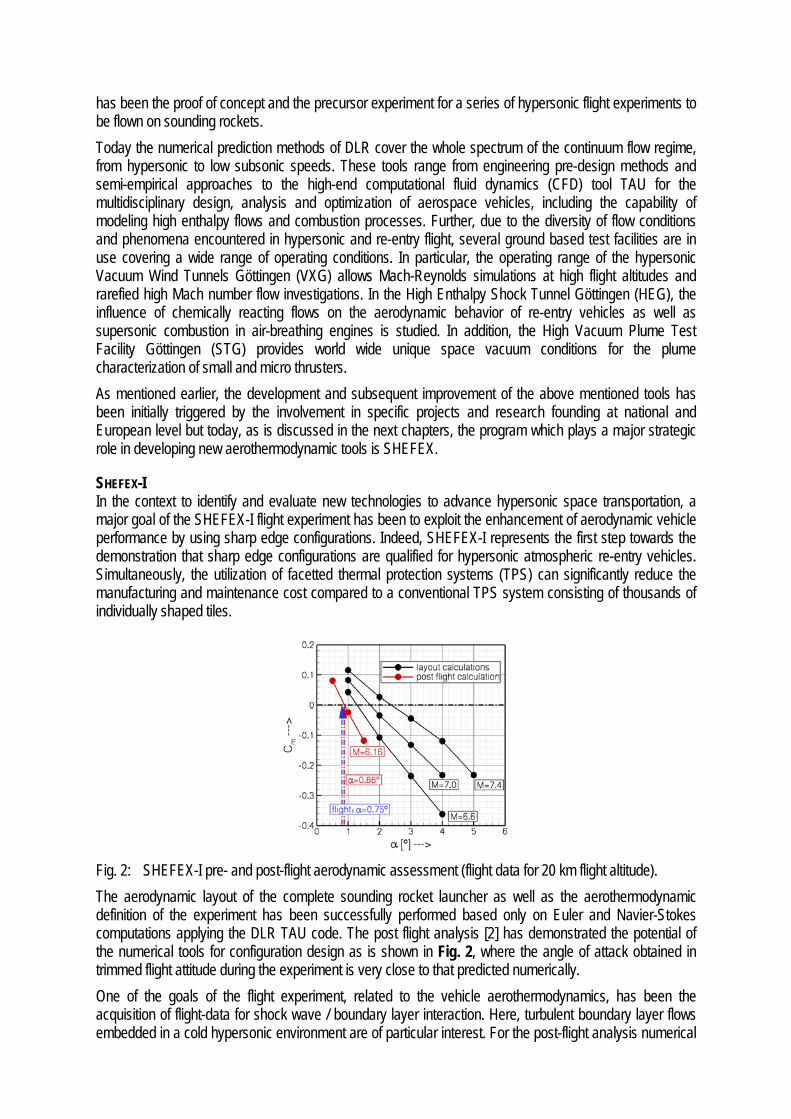
In support to the SHEFEX-I flight experiment, important complementary activities have been carried out for the assessment of physical models to describe for example turbulent flows; shock-shock interaction; shock-wave boundary-layer interaction and fluid-/thermal-mechanical structure coupling effects. The correct numerical modeling of highly separated flows occurring e.g. in the wake of re-entry configurations at high angles of attack is important for the determination of their aerodynamic behavior. In order to obtain realistic description of separated unsteady base flows, detailed studies of the applicability of modern turbulence models such as DES have been carried out with the TAU code during the last years [4]. Figure 5 indicates that the selection of an inappropriate turbulence model has a strong impact on the base drag prediction. For the considered cylinder configuration, the pressure coefficient on the base is underestimated by almost 50% when applying a classical RANS turbulence model.
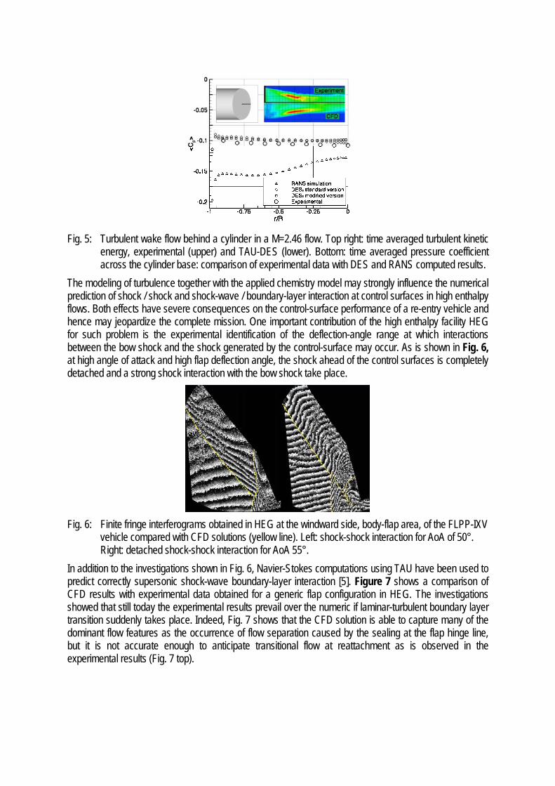
Fig. 5: Turbulent wake flow behind a cylinder in a M=2.46 flow. Top right: time averaged turbulent kinetic
energy, experimental (upper) and TAU-DES (lower). Bottom: time averaged pressure coefficient across the cylinder base: comparison of experimental data with DES and RANS computed results.
The modeling of turbulence together with the applied chemistry model may strongly influence the numerical prediction of shock / shock and shock-wave / boundary-layer interaction at control surfaces in high enthalpy flows. Both effects have severe consequences on the control-surface performance of a re-entry vehicle and hence may jeopardize the complete mission. One important contribution of the high enthalpy facility HEG for such problem is the experimental identification of the deflection-angle range at which interactions between the bow shock and the shock generated by the control-surface may occur. As is shown in Fig. 6, at high angle of attack and high flap deflection angle, the shock ahead of the control surfaces is completely detached and a strong shock interaction with the bow shock take place.
Fig. 6: Finite fringe interferograms obtained in HEG at the windward side, body-flap area, of the FLPP-IXV
vehicle compared with CFD solutions (yellow line). Left: shock-shock interaction for AoA of 50°. Right: detached shock-shock interaction for AoA 55°.
In addition to the investigations shown in Fig. 6, Navier-Stokes computations using TAU have been used to predict correctly supersonic shock-wave boundary-layer interaction [5]. Figure 7 shows a comparison of CFD results with experimental data obtained for a generic flap configuration in HEG. The investigations showed that still today the experimental results prevail over the numeric if laminar-turbulent boundary layer transition suddenly takes place. Indeed, Fig. 7 shows that the CFD solution is able to capture many of the dominant flow features as the occurrence of flow separation caused by the sealing at the flap hinge line, but it is not accurate enough to anticipate transitional flow at reattachment as is observed in the experimental results (Fig. 7 top).

q' /q' 0
0.0 0.2 0.4 0.6 0.8 1.0 1.2 1.4 1.6 1.8 2.0 2.20.000.050.100.150.200.250.300.350.400.450.50
xz
y
x/L
q' /q' 0
0.0 0.2 0.4 0.6 0.8 1.0 1.2 1.4 1.6 1.8 2.0 2.20.000.050.100.150.200.250.300.350.400.450.50
CFD; openEXP; open
gap gap
CFD; closed gapEXP; closed gap
Fig. 7: Computed (TAU) and measured (HEG) normalized heat flux distribution for a 20° deflected
generic-flap configuration in a high enthalpy flow. Top: hinge-line gap closed. Bottom: open. Coupled simulations including aerothermodynamics and structure modeling were performed in the past for generic nose cap and flap geometries. The numerical investigation of a generic space vehicle control surface was performed utilizing the TAU code coupled to a structure mechanics solver via a surface interpolation routine. The study showed that due to strong coupling effects between the fluid and the structure, the temperature peaks occurring for example at contour edges in stand alone CFD solutions are not observed in the results of coupled computations [6]. In Fig. 8 this effect is observed at the edge of the open hinge line gap of a generic flap configuration.
Fig. 8: Measured (LBK) and computed (TAU) temperature distribution along the surface of a generic flap
configuration with open hinge line gap. The thermo mechanically coupled analysis of the flow past a generic nose model of a hypersonic vehicle was performed to investigate the effects of heat conduction inside the structure and deformations based on external pressure loads. The numerical results [7] could reproduce the experimental data, showing good qualitative and satisfactory quantitative agreement with the temporal temperature development measured during the experiments as is shown in Fig. 9.
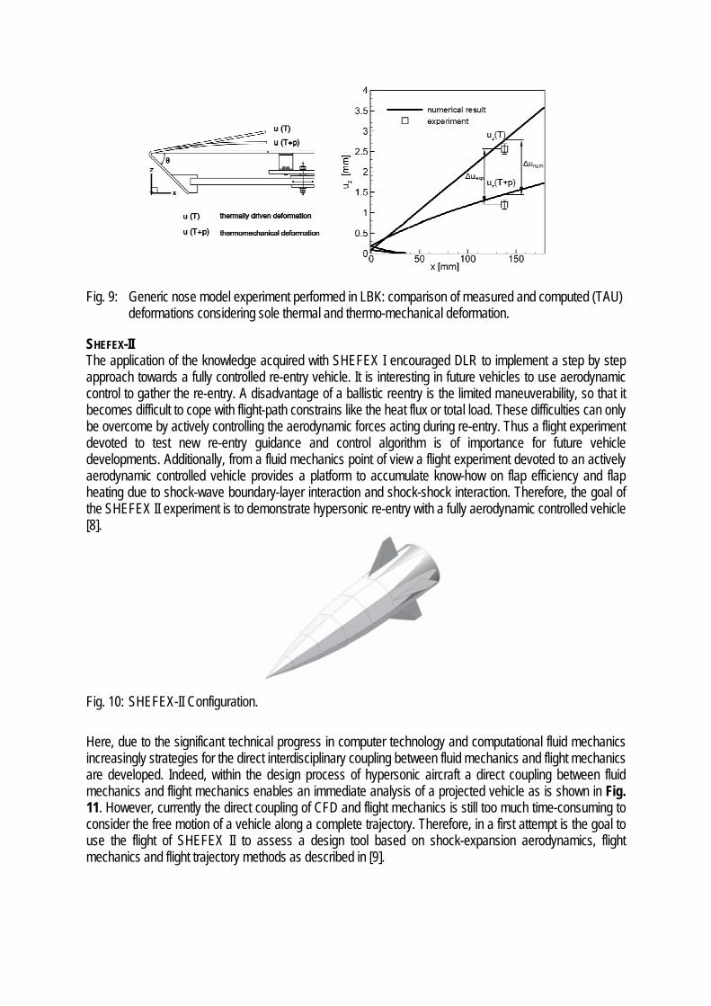
Fig. 9: Generic nose model experiment performed in LBK: comparison of measured and computed (TAU)
deformations considering sole thermal and thermo-mechanical deformation.
SHEFEX-II The application of the knowledge acquired with SHEFEX I encouraged DLR to implement a step by step approach towards a fully controlled re-entry vehicle. It is interesting in future vehicles to use aerodynamic control to gather the re-entry. A disadvantage of a ballistic reentry is the limited maneuverability, so that it becomes difficult to cope with flight-path constrains like the heat flux or total load. These difficulties can only be overcome by actively controlling the aerodynamic forces acting during re-entry. Thus a flight experiment devoted to test new re-entry guidance and control algorithm is of importance for future vehicle developments. Additionally, from a fluid mechanics point of view a flight experiment devoted to an actively aerodynamic controlled vehicle provides a platform to accumulate know-how on flap efficiency and flap heating due to shock-wave boundary-layer interaction and shock-shock interaction. Therefore, the goal of the SHEFEX II experiment is to demonstrate hypersonic re-entry with a fully aerodynamic controlled vehicle [8].
Fig. 10: SHEFEX-II Configuration. Here, due to the significant technical progress in computer technology and computational fluid mechanics increasingly strategies for the direct interdisciplinary coupling between fluid mechanics and flight mechanics are developed. Indeed, within the design process of hypersonic aircraft a direct coupling between fluid mechanics and flight mechanics enables an immediate analysis of a projected vehicle as is shown in Fig. 11. However, currently the direct coupling of CFD and flight mechanics is still too much time-consuming to consider the free motion of a vehicle along a complete trajectory. Therefore, in a first attempt is the goal to use the flight of SHEFEX II to assess a design tool based on shock-expansion aerodynamics, flight mechanics and flight trajectory methods as described in [9].

Fig. 11: Influence of the spin rate on the motion of a bi-conic capsule in hypersonic flow. While currently this code is well suited for the definition of staged sounding rocket experiments, in future applications more sophisticated fluid mechanic methods like the DLR Euler- and Navier-Stokes code TAU, may be easily introduced. Indeed, recently a 6-DOF motion model has been implemented in TAU which couples numerical aerodynamic simulations with rigid body motions directly. But the simulation of maneuvers of complex vehicles requires the consideration of control surfaces. The integration of control surfaces provides a challenge for numerical investigations due to the treatment of mesh, which must move with the control surface. Here a new approach for the technique of overlaid grids, Chimera-Technique, is utilized to integrate the control surfaces [10]. This new multi-disciplinary approach, to be validated through the SHEFEX II flight experiment, will help the design of future hypersonic vehicles and control systems. In particular, the envisaged method offers more precise dynamic analysis allowing also accurate prediction of the dynamic behavior of hypersonic vehicles, a feature of strong importance with respect to non-winged configurations like lifting bodies and capsules (Fig. 12).
Fig. 12: Instantaneous pressure field computed with TAU for the PRE-X space vehicle approaching to
landing, AoA=70 deg., Ma=0.8. Left: Upstroke motion, right: Downstroke motion.
SHEFEX-III
Fig. 13: Concepts study for SHEFEX-III. The technology requirements for SHEFEX-III are derived with view to a Free Flyer concept for a returnable and reusable orbital experiment facility. Such a platform should feature a very high quality level of microgravity during its missions, whose durations may vary from approximately 30 minutes up to several weeks. A key feature here is the reliable return of samples, data and experimental equipment [11]. Due to

the de-orbit operations, here plume flows, in particular nozzle flows, are also of concern requiring a reliable prediction of stationary and transient phenomena occurring inside the nozzle. In Fig. 14 the numerical investigation of a dual-bell nozzle is exemplarily shown [12]. A demand which has to be met by the numerical tool is the correct modeling of the interaction of the high Mach number core flow with the subsonic recirculation zones, turbulent shear layers and the shock system between the high speed core and the recirculation zones. For the here mentioned example, the experimental wall pressure distributions and locations of the transition point could be reproduced by CFD with good agreement for a wide range of chamber pressures. Also the hysteresis, knowledge of which is important to prevent the nozzle from running into a flip-flop regime, has been clearly reproduced in the CFD results.
Fig. 14: Snapshot resulting from a time accurate numerical computation (TAU) of the flow in a dual-bell
rocket nozzle; Mach number contours, iso-surface of M=3 and streamlines in a cutting plane (p0 = nozzle reservoir pressure, pa = ambient pressure).
Further, the development of SHEFEX-III is supported by establishing a design database for reaction control systems. In this framework the interaction of control thrusters with the external supersonic and/or hypersonic flow has been investigated [13]. A particular effort focused on clarifying the influence of flight altitude, Mach number and high temperature effects on the efficiency of thruster based reaction control systems. Extensive parameter variations provided predictions of the efficiency of a side jet operated in variable altitudes at super- and hypersonic flight conditions. Furthermore, various flight attitudes including nose pitch up and down have been considered and qualified as is shown in Fig. 15.
Fig. 15: Numerical assessment of the thrust amplification factor of a reaction control system embedded in a
hypersonic free stream flow for different altitudes and free stream Mach numbers. At high altitude, the complete theoretical treatment of the flow phenomena requires the solution of the Navier-Stokes equations for continuum flow as well as even more complicated description of the transition- and free molecular flow regimes, where high rarefaction and strong thermal non-equilibrium prevail. A

unifying approach is currently pursued on the basis of coupling the DLR TAU code for continuum flow and a newly designed Direct Simulation Monte Carlo (DSMC) method for the rarefied flow regime (Fig. 16).
Fig. 16: TAU computations of the plume expansion in space vacuum conditions. Top: combined Navier-
Stokes and DSMC approach. Bottom: Stand-alone Navier-Stokes solution.
FINAL REMARKS In order to advance hypersonic space transportation such that it becomes an affordable and reliable routine operation as the air transportation of today, essential improvements, far beyond current technologies are required to fulfill mission and safety constraints and to ensure economic viability. In this framework, an increasing role of the computational fluid dynamics is observed. The growing importance of optimization strategies in the design process, involving the coupling of many disciplines is being possible due to the use of modern computational cluster resources and due to the validation of the applied numerical tools by means of carefully designed complex experiments carried out in ground based facilities and through efficiently flight demonstration. A major concern related to the physical modeling employed by the CFD methods is the availability of experimental data for model validation in the hot hypersonic regime. While high fidelity CFD results are today based on the solution of the Navier-Stokes equations, they still require validated models to account for laminar / turbulent transition, turbulence as well as high temperature and combustion effects. Improvements of these physical models require considerable progress in novel non-intrusive measurement techniques. Further, future ground testing has to answer more system related questions and therefore the test configurations will be more complex. The development and demonstration of new technologies need a combination of systematic ground tests and efficient, more demanding, flight experiments. Thus, the three design tools, namely CFD, ground based testing and flight experiments, need to be continuously improved and linked in an optimal manner in order to accomplish the above mentioned objective. REFERENCES [1] Longo J.M.A.; SHEFEX-I a Low Cost Highly Efficient Flight Experiment. Proceedings of the 5th European Symposium on Aerothermodynamics for Space Vehicles, Cologne, Germany (2004). [2] Eggers Th.; Barth T.; Aerodynamic Analysis of the DLR Flight Experiment SHEFEX-I. AIAA paper AIAA-2006-8027, Canberra, Australia (2006). [3] Longo J.M.A.; Barth T.; Eggers Th.; Aerothermodynamic issues of the DLR hypersonic fight experiment SHEFEX I. Proceedings AIAA, 38th Fluid Dynamics Conference, Invited Paper, AIAA 2008-4038, Seattle, USA (2008). [4] Togiti V.; Lüdeke H.; Computation of Supersonic Base Flow Using Detached Eddy Simulation. STAB 2006, Notes on Numerical Fluid Mechanics and Multidisciplinary Design, Vol. 96 (2007), pp. 389-396. [5] Reimann, B.; Martinez-Schramm, J.; Hoffie, A.; Aerothermodynamic study of a generic flap configuration with slit in HEG. 6th European Symposium on Aerothermodynamics for Space Vehicles, Versailles, France (2008).

[6] Mack A.; Schaefer R.; Fluid Structure Interaction on a Generic Body-Flap Model in Hypersonic Flow. Journal of Spacecraft and Rockets, Vol. 42, No. 5, 2005, pp. 769-779. [7] Mack A.; Aerothermodynamic behaviour of a generic nosecap model including thermochemical structural effects. Aerospace Science and Technology 11 (2007) 386-395. [8] Weihs H.; Longo J.M.A.; Turner J.; The Sharp Edge Flight Experiment SHEFEX II, a Mission Overview and Status. AIAA 15th Space Planes and Hypersonic Systems and Technologies Conference, Ohio, USA (2008). [9] Eggers Th.; Gräßlin M.; Layout of Hypersonic Vehicles by Coupling of Aerodynamics and Flight mechanics. Proceedings of the 2nd International ARA Days, Arcachon, France (2008). [10] Korfanty M.; CFD based Dynamic Analysis of Atmospheric Re-entry Vehicles. Proceedings of the 2nd International ARA Days, Arcachon, France (2008). [11] Eßmann O.; Longo J.M.A.; Weihs H.; REX-Free Flyer: a Reusable Orbital Return Vehicle for Experiments under Microgravity Conditions. 59th International Astronautical Congress, Glasgow, Scotland (2008), paper IAC-08-A2.5.08. [12] Karl K.; Hannemann K.; Numerical Investigation of Transient Flow Phenomena in Dual-Bell Nozzles. Proceedings of the 6th International Symposium on Launcher Technologies, Munich, Germany (2005). [13] Adeli R.; “Influence of a reaction control jet in super- and hypersonic flow fields”, Dissertation Technische Universität Darmstadt, Germany (2007), DLR FB 2007-09.


![Jobs2 tep[1]](https://img.pdfslide.us/doc/110x75/54990221b4795938518b459d/jobs2-tep1.jpg)