Embed Size (px)
Citation preview
Proceedings World Geothermal Congress 2005 Antalya, Turkey, 24-29 April 2005
1
Technological Developments in Deep Drilling in the Larderello Area
Alessandro Lazzarotto and Fabio Sabatelli
Enel GEM Geothermal Production, Via A. Pisano 120, 56122 Pisa, Italy
[email protected]; [email protected]
Keywords: Drilling, Geothermal Well, Multilateral Well, Deep Exploration, Larderello, Italy.
ABSTRACT
The most recent technological developments in the deep drilling of geothermal wells in the Larderello area are described in this paper.
Environmental compliance of the drilling operations has been enhanced by means of noise reduction through soundproofing of the drilling rig and associated equipment; moreover, significant advance was made in the reduction and recycling of the debris produced.
New techniques for plugging absorbing zones have been used, coupled with modified cement slurries, with consequent substantial improvement of the casing cementing works.
Corrosion-resistant casing materials are being used near and up to the wellhead, as well as wellhead coated components, so as to insure an extended life in presence of steam containing acid-chlorides. Steam scrubbing may thus be carried out at wellhead, instead of down hole, even at moderate steam superheating conditions.
Finally, the drilling of multilateral wells with the use of retrievable whipstocks was recently tested with success in highly demanding well conditions. This technique will prove very useful in reducing the cost of drilling in low-permeability reservoirs.
1. INTRODUCTION
Enel has always maintained a drilling department (rigs and personnel) since the beginning of the geothermal development, in order to be able to carry out on its own the drilling of geothermal wells, for both field exploration and development.
Enel capabilities include well design, cementing jobs, mud service and mud logging, fishing operations and related activities.
At present, Enel drilling department operates all the year round with three drilling crews, using four high-capacity rigs (Mas 6000) for deep wells (3,500-4,000 m depth), one medium-capacity rig (MR 7000; up to 2,500 m depth) and a smaller rig (ST 6) for shallow wells (up to 1,000 m depth) and work over.
Mas 6000 1700 453 272 604
MR 7000 700 159 113 227
ST 6 175 50 40 70
Gross capacity
tonRig
Draw work
horsepowe
Casing capacity
ton
Set-back capacity
ton
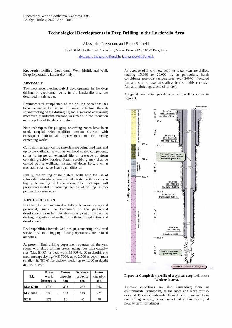
An average of 5 to 6 new deep wells per year are drilled, totaling 15,000 to 20,000 m, in particularly harsh conditions: reservoir temperatures over 300°C, fractured formations to be cased at shallow depths, highly corrosive formation fluids (gas, acid chlorides).
A typical completion profile of a deep well is shown in Figure 1.
Figure 1: Completion profile of a typical deep well in the Larderello area.
Ambient conditions are also demanding from an environmental standpoint, as the more and more tourist-oriented Tuscan countryside demands a soft impact from the drilling activity, often carried out in the vicinity of holiday farms or villages.
Lazzarotto and Sabatelli
2
Enel supplied its drilling services (rig and crew) also in the framework of the European Hot Dry Rock program at Soultz-sous-Forêts (France), where 3 deep wells were drilled between 1999 and 2004, with GPK 4 directional well, completed in April, 2004 being the deepest geothermal well in the world at 5,260 m of measured depth.
Moreover, Enel personnel are in charge of the technical supervision of the drilling activity currently carried out in El Salvador for the exploration and development of Berlin and Cuyaunausul fields.
Having to face new challenges continuously, the need for environmental and technological developments has become apparent.
This paper describes the main advances made in the field of deep drilling in the Larderello area and surroundings during the last years.
2. ENVIRONMENTAL DEVELOPMENTS
The main environmental issues associated with drilling operations are land occupation (drilling pads), water use (TLC, i.e. total loss of circulation, already occurs at shallow depths), noise emissions and disposal of rock debris, as subsequently described.
2.1 Land occupation and drilling pads
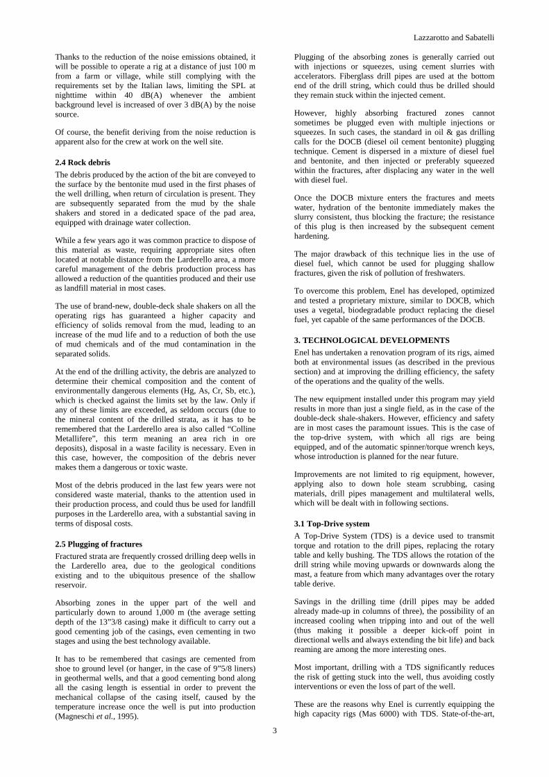
The dimensions of a typical drilling pad have been reduced to a minimum; moreover, a substantial part of this area (e.g. for the debris storage) is restored after the drilling is over. Figure 2 shows the typical layout and dimensions of a drilling pad.
Figure 2: Drilling pad in the Larderello area.
The connections of the wellheads to the chloride scrubbing and separation plant (whenever present) and to the steam pipeline are designed so as to allow for the rig-up and the work over of any well on a pad while maintaining the other wells on the same pad in production.
A substantial saving in land occupation of geothermal projects has been obtained with the drilling of three or more wells on a single pad, the first one vertical, the following ones directional. Enel’s experience in directional drilling dates back to 1983 (Bianchi et al., 1995).
2.2 Water use
Water consumption during drilling operations is limited in the initial phases, where mud is used (prepared with fresh water) and return of circulation is present.
However, as soon as the fractured zones in the shallow reservoir are reached (at a depth of a few hundred meters in the Larderello area), or soon after the casings are set in the subsequent phases, total loss of circulation (TLC) occurs. Thus, most of the open hole (8”½) part of the well (typically deeper than 2,000 m) is drilled in TLC, requiring a water flow rate of 40-80 m3/h.
As surface waters are scarce in the Larderello area and their use must be kept to a minimum, geothermal steam condensate is used in these phases, connecting the active drilling pad with the nearest power plant(s) by means of adequate water pipelines. Pollution of the surface water strata is prevented, as condensate is used only after their confinement by the casing already set in place.
2.3 Noise emissions
All of the rigs used by Enel (except the smallest one) are of the diesel-electric type. The major sources of noise emissions are the diesel generators (although already soundproofed), the draw work, the rotary table, the shale shakers and other ancillary equipment.
As a first step, noise emissions in the various operating phases were characterized by measurement campaigns, recording sound pressure levels at various locations within the drilling pad and outside it. The acoustic power of the single emitting sources was then calculated by means of an adequate model.
On the basis of these data, soundproofing of the rig and of the associated equipment (including a new, increased efficiency soundproofing of the diesel generators) was commissioned, aimed at a 12-15 dB(A) reduction of the sound pressure level in the noisiest operating conditions.
At the same time, the soundproofing elements had to be easily mounted and dismounted (minimum increase in rig-up and rig-down duration) and should not interfere with the routine maintenance, nor raise safety concerns for the crew.
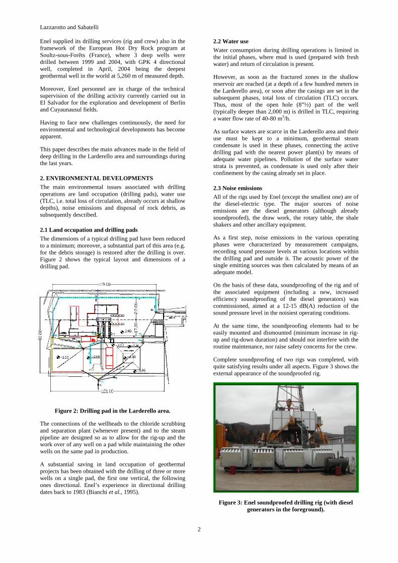
Complete soundproofing of two rigs was completed, with quite satisfying results under all aspects. Figure 3 shows the external appearance of the soundproofed rig.
Figure 3: Enel soundproofed drilling rig (with diesel generators in the foreground).
Lazzarotto and Sabatelli
3
Thanks to the reduction of the noise emissions obtained, it will be possible to operate a rig at a distance of just 100 m from a farm or village, while still complying with the requirements set by the Italian laws, limiting the SPL at nighttime within 40 dB(A) whenever the ambient background level is increased of over 3 dB(A) by the noise source.
Of course, the benefit deriving from the noise reduction is apparent also for the crew at work on the well site.
2.4 Rock debris
The debris produced by the action of the bit are conveyed to the surface by the bentonite mud used in the first phases of the well drilling, when return of circulation is present. They are subsequently separated from the mud by the shale shakers and stored in a dedicated space of the pad area, equipped with drainage water collection.
While a few years ago it was common practice to dispose of this material as waste, requiring appropriate sites often located at notable distance from the Larderello area, a more careful management of the debris production process has allowed a reduction of the quantities produced and their use as landfill material in most cases.
The use of brand-new, double-deck shale shakers on all the operating rigs has guaranteed a higher capacity and efficiency of solids removal from the mud, leading to an increase of the mud life and to a reduction of both the use of mud chemicals and of the mud contamination in the separated solids.
At the end of the drilling activity, the debris are analyzed to determine their chemical composition and the content of environmentally dangerous elements (Hg, As, Cr, Sb, etc.), which is checked against the limits set by the law. Only if any of these limits are exceeded, as seldom occurs (due to the mineral content of the drilled strata, as it has to be remembered that the Larderello area is also called “Colline Metallifere”, this term meaning an area rich in ore deposits), disposal in a waste facility is necessary. Even in this case, however, the composition of the debris never makes them a dangerous or toxic waste.
Most of the debris produced in the last few years were not considered waste material, thanks to the attention used in their production process, and could thus be used for landfill purposes in the Larderello area, with a substantial saving in terms of disposal costs.
2.5 Plugging of fractures
Fractured strata are frequently crossed drilling deep wells in the Larderello area, due to the geological conditions existing and to the ubiquitous presence of the shallow reservoir.
Absorbing zones in the upper part of the well and particularly down to around 1,000 m (the average setting depth of the 13”3/8 casing) make it difficult to carry out a good cementing job of the casings, even cementing in two stages and using the best technology available.
It has to be remembered that casings are cemented from shoe to ground level (or hanger, in the case of 9”5/8 liners) in geothermal wells, and that a good cementing bond along all the casing length is essential in order to prevent the mechanical collapse of the casing itself, caused by the temperature increase once the well is put into production (Magneschi et al., 1995).
Plugging of the absorbing zones is generally carried out with injections or squeezes, using cement slurries with accelerators. Fiberglass drill pipes are used at the bottom end of the drill string, which could thus be drilled should they remain stuck within the injected cement.
However, highly absorbing fractured zones cannot sometimes be plugged even with multiple injections or squeezes. In such cases, the standard in oil & gas drilling calls for the DOCB (diesel oil cement bentonite) plugging technique. Cement is dispersed in a mixture of diesel fuel and bentonite, and then injected or preferably squeezed within the fractures, after displacing any water in the well with diesel fuel.
Once the DOCB mixture enters the fractures and meets water, hydration of the bentonite immediately makes the slurry consistent, thus blocking the fracture; the resistance of this plug is then increased by the subsequent cement hardening.
The major drawback of this technique lies in the use of diesel fuel, which cannot be used for plugging shallow fractures, given the risk of pollution of freshwaters.
To overcome this problem, Enel has developed, optimized and tested a proprietary mixture, similar to DOCB, which uses a vegetal, biodegradable product replacing the diesel fuel, yet capable of the same performances of the DOCB.
3. TECHNOLOGICAL DEVELOPMENTS
Enel has undertaken a renovation program of its rigs, aimed both at environmental issues (as described in the previous section) and at improving the drilling efficiency, the safety of the operations and the quality of the wells.
The new equipment installed under this program may yield results in more than just a single field, as in the case of the double-deck shale-shakers. However, efficiency and safety are in most cases the paramount issues. This is the case of the top-drive system, with which all rigs are being equipped, and of the automatic spinner/torque wrench keys, whose introduction is planned for the near future.
Improvements are not limited to rig equipment, however, applying also to down hole steam scrubbing, casing materials, drill pipes management and multilateral wells, which will be dealt with in following sections.
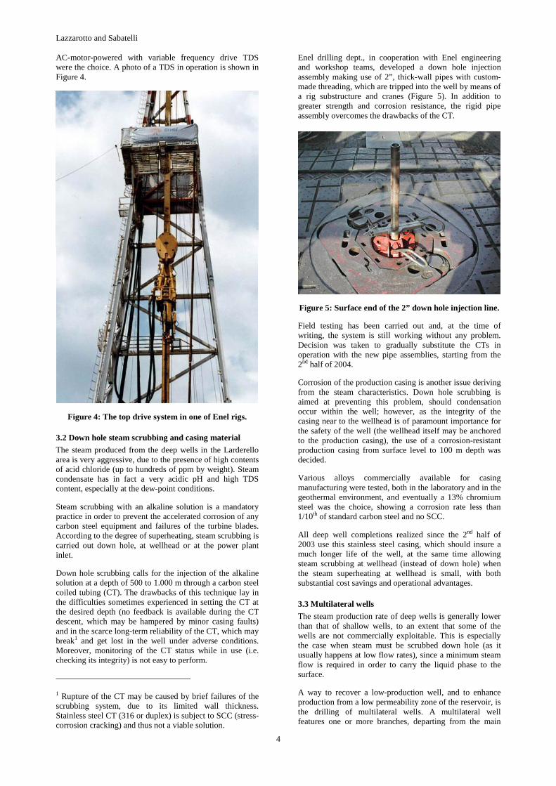
3.1 Top-Drive system
A Top-Drive System (TDS) is a device used to transmit torque and rotation to the drill pipes, replacing the rotary table and kelly bushing. The TDS allows the rotation of the drill string while moving upwards or downwards along the mast, a feature from which many advantages over the rotary table derive.
Savings in the drilling time (drill pipes may be added already made-up in columns of three), the possibility of an increased cooling when tripping into and out of the well (thus making it possible a deeper kick-off point in directional wells and always extending the bit life) and back reaming are among the more interesting ones.
Most important, drilling with a TDS significantly reduces the risk of getting stuck into the well, thus avoiding costly interventions or even the loss of part of the well.
These are the reasons why Enel is currently equipping the high capacity rigs (Mas 6000) with TDS. State-of-the-art,
Lazzarotto and Sabatelli
4
AC-motor-powered with variable frequency drive TDS were the choice. A photo of a TDS in operation is shown in Figure 4.
Figure 4: The top drive system in one of Enel rigs.
3.2 Down hole steam scrubbing and casing material
The steam produced from the deep wells in the Larderello area is very aggressive, due to the presence of high contents of acid chloride (up to hundreds of ppm by weight). Steam condensate has in fact a very acidic pH and high TDS content, especially at the dew-point conditions.
Steam scrubbing with an alkaline solution is a mandatory practice in order to prevent the accelerated corrosion of any carbon steel equipment and failures of the turbine blades. According to the degree of superheating, steam scrubbing is carried out down hole, at wellhead or at the power plant inlet.
Down hole scrubbing calls for the injection of the alkaline solution at a depth of 500 to 1.000 m through a carbon steel coiled tubing (CT). The drawbacks of this technique lay in the difficulties sometimes experienced in setting the CT at the desired depth (no feedback is available during the CT descent, which may be hampered by minor casing faults) and in the scarce long-term reliability of the CT, which may break1 and get lost in the well under adverse conditions. Moreover, monitoring of the CT status while in use (i.e. checking its integrity) is not easy to perform.
1 Rupture of the CT may be caused by brief failures of the scrubbing system, due to its limited wall thickness. Stainless steel CT (316 or duplex) is subject to SCC (stress-corrosion cracking) and thus not a viable solution.
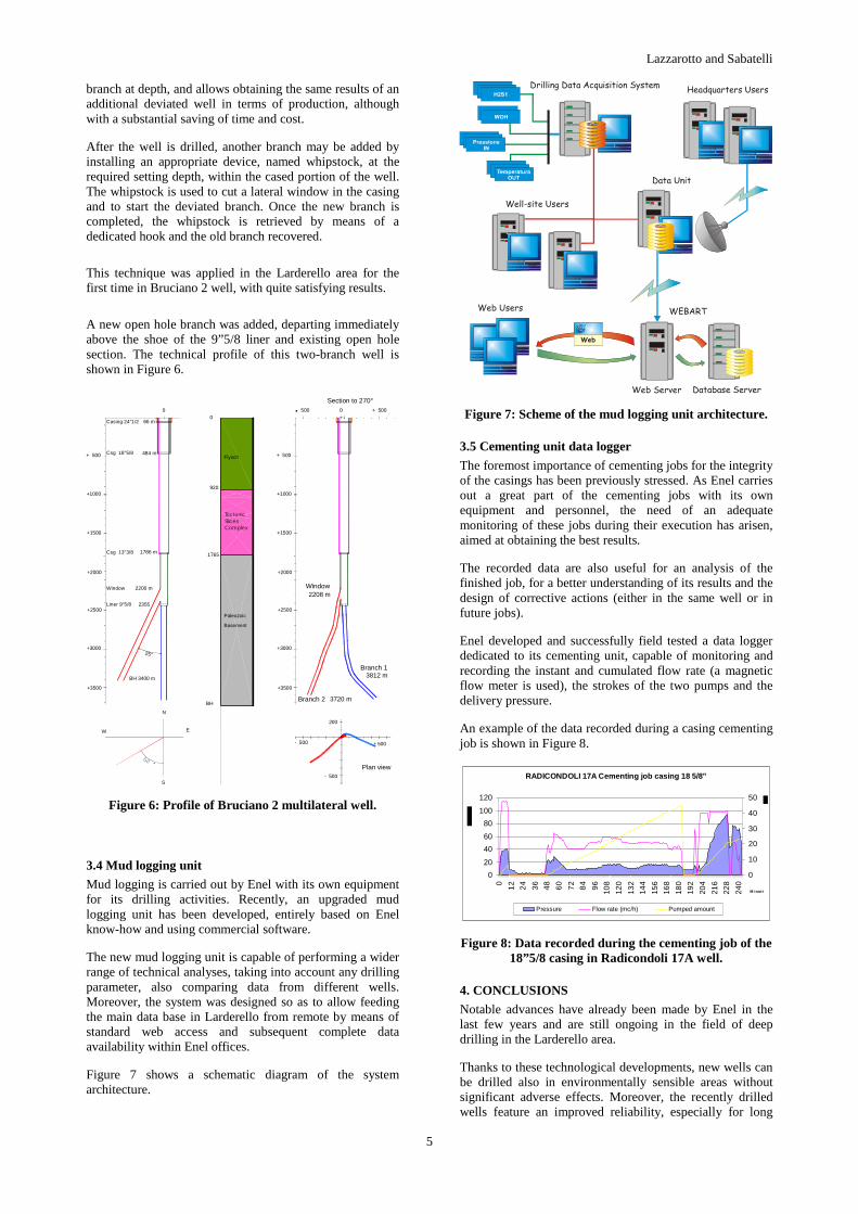
Enel drilling dept., in cooperation with Enel engineering and workshop teams, developed a down hole injection assembly making use of 2”, thick-wall pipes with custom-made threading, which are tripped into the well by means of a rig substructure and cranes (Figure 5). In addition to greater strength and corrosion resistance, the rigid pipe assembly overcomes the drawbacks of the CT.
Figure 5: Surface end of the 2” down hole injection line.
Field testing has been carried out and, at the time of writing, the system is still working without any problem. Decision was taken to gradually substitute the CTs in operation with the new pipe assemblies, starting from the 2nd half of 2004.
Corrosion of the production casing is another issue deriving from the steam characteristics. Down hole scrubbing is aimed at preventing this problem, should condensation occur within the well; however, as the integrity of the casing near to the wellhead is of paramount importance for the safety of the well (the wellhead itself may be anchored to the production casing), the use of a corrosion-resistant production casing from surface level to 100 m depth was decided.
Various alloys commercially available for casing manufacturing were tested, both in the laboratory and in the geothermal environment, and eventually a 13% chromium steel was the choice, showing a corrosion rate less than 1/10th of standard carbon steel and no SCC.
All deep well completions realized since the 2nd half of 2003 use this stainless steel casing, which should insure a much longer life of the well, at the same time allowing steam scrubbing at wellhead (instead of down hole) when the steam superheating at wellhead is small, with both substantial cost savings and operational advantages.
3.3 Multilateral wells
The steam production rate of deep wells is generally lower than that of shallow wells, to an extent that some of the wells are not commercially exploitable. This is especially the case when steam must be scrubbed down hole (as it usually happens at low flow rates), since a minimum steam flow is required in order to carry the liquid phase to the surface.
A way to recover a low-production well, and to enhance production from a low permeability zone of the reservoir, is the drilling of multilateral wells. A multilateral well features one or more branches, departing from the main
Lazzarotto and Sabatelli
5
branch at depth, and allows obtaining the same results of an additional deviated well in terms of production, although with a substantial saving of time and cost.
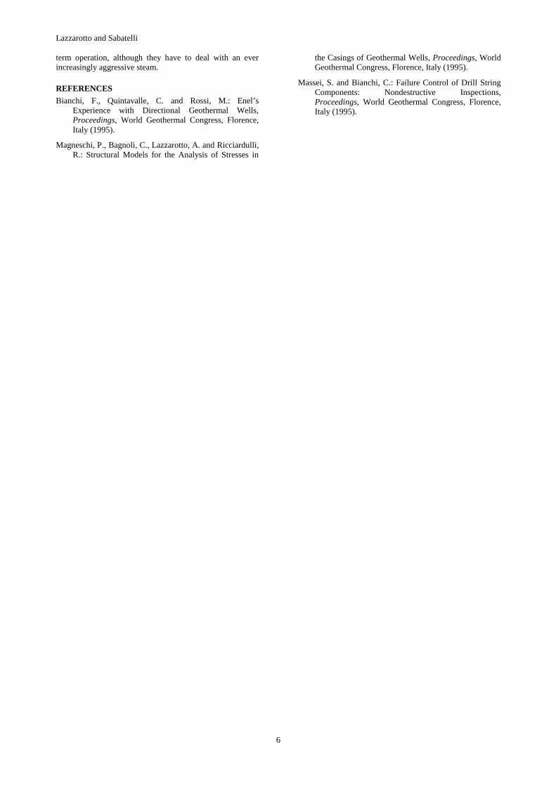
After the well is drilled, another branch may be added by installing an appropriate device, named whipstock, at the required setting depth, within the cased portion of the well. The whipstock is used to cut a lateral window in the casing and to start the deviated branch. Once the new branch is completed, the whipstock is retrieved by means of a dedicated hook and the old branch recovered.
This technique was applied in the Larderello area for the first time in Bruciano 2 well, with quite satisfying results.
A new open hole branch was added, departing immediately above the shoe of the 9”5/8 liner and existing open hole section. The technical profile of this two-branch well is shown in Figure 6.
+ 500
+1000
+1500
+2000
+2500
+3000
+3500
500 0 + 500
- 500
200
- 500 + 500
Plan view
Branch 1
Branch 2
0
25°
2200 m
1786 m
484 m
66 m
2355
+ 500
+1000
+1500
+2000
+2500
+3000
+3500
920
1765
BH
Section to 270°
0
BH 3400 m
Paleozoic
Basement
Flysch
N
W E
S
3812 m
3720 m
Window2208 m
Casing 24"1/2
Csg 18"5/8
Csg 13"3/8
Liner 9"5/8
Window
TectonicSlicesComplex
Figure 6: Profile of Bruciano 2 multilateral well.
3.4 Mud logging unit
Mud logging is carried out by Enel with its own equipment for its drilling activities. Recently, an upgraded mud logging unit has been developed, entirely based on Enel know-how and using commercial software.
The new mud logging unit is capable of performing a wider range of technical analyses, taking into account any drilling parameter, also comparing data from different wells. Moreover, the system was designed so as to allow feeding the main data base in Larderello from remote by means of standard web access and subsequent complete data availability within Enel offices.
Figure 7 shows a schematic diagram of the system architecture.
Drilling Data Acquisition System
Data Unit
Headquarters Users
Database ServerWeb Server
WEBART
Well-site Users
Web Users
Web
Figure 7: Scheme of the mud logging unit architecture.
3.5 Cementing unit data logger
The foremost importance of cementing jobs for the integrity of the casings has been previously stressed. As Enel carries out a great part of the cementing jobs with its own equipment and personnel, the need of an adequate monitoring of these jobs during their execution has arisen, aimed at obtaining the best results.
The recorded data are also useful for an analysis of the finished job, for a better understanding of its results and the design of corrective actions (either in the same well or in future jobs).
Enel developed and successfully field tested a data logger dedicated to its cementing unit, capable of monitoring and recording the instant and cumulated flow rate (a magnetic flow meter is used), the strokes of the two pumps and the delivery pressure.
An example of the data recorded during a casing cementing job is shown in Figure 8.
RADICONDOLI 17A Cementing job casing 18 5/8"
0
20
40
60
80
100
120
0
12
24
36
48
60
72
84
96
108
120
132
144
156
168
180
192
204
216
228
240
M inut i
0
10
20
30
40
50
Pressure Flow rate (mc/h) Pumped amount
Figure 8: Data recorded during the cementing job of the 18”5/8 casing in Radicondoli 17A well.
4. CONCLUSIONS
Notable advances have already been made by Enel in the last few years and are still ongoing in the field of deep drilling in the Larderello area.
Thanks to these technological developments, new wells can be drilled also in environmentally sensible areas without significant adverse effects. Moreover, the recently drilled wells feature an improved reliability, especially for long
Lazzarotto and Sabatelli
6
term operation, although they have to deal with an ever increasingly aggressive steam.
REFERENCES
Bianchi, F., Quintavalle, C. and Rossi, M.: Enel’s Experience with Directional Geothermal Wells, Proceedings, World Geothermal Congress, Florence, Italy (1995).
Magneschi, P., Bagnoli, C., Lazzarotto, A. and Ricciardulli, R.: Structural Models for the Analysis of Stresses in
the Casings of Geothermal Wells, Proceedings, World Geothermal Congress, Florence, Italy (1995).
Massei, S. and Bianchi, C.: Failure Control of Drill String Components: Nondestructive Inspections, Proceedings, World Geothermal Congress, Florence, Italy (1995).