Embed Size (px)
Citation preview

5/22/2013 1
Technological challenges and development of instrumentation sensors and techniques
for Indian Advanced Heavy Water Reactor (AHWR)
Rajalakshmi.R Bhabha Atomic Research Centre
Mumbai, INDIA
Technical Meeting on “Instrumentation and Control in Advanced Small and Medium-sized Reactors (SMRs)”
21 - 24 May 2013 VIC, Vienna, Austria

5/22/2013 2
The Indian Advanced Heavy Water Reactor (AHWR)
Indian AHWR is a 300 MWe, vertical, pressure tube type, heavy water moderated and boiling light water cooled natural circulation reactor using (Th-233U )MOX and (Th-Pu) MOX fuel. (An innovative configuration that can provide low risk nuclear energy using available technologies)
Safety and security – Indian Technological approach
No unacceptable radiological impact outside the plant boundary with (a)Failure of all active systems, and
(b)Failure of external infrastructure to provide coolant, power and other services, and
(c)Malevolent acts by an insider, one of the consequences of which is the failure of instrumentation signal initiated shutdown actions, and
(d)Inability of plant operators to manage the events and their consequences, for a significantly long time.
5/22/2013 3
The Indian Advanced Heavy Water Reactor (AHWR)
Safety and security – Indian Technological approach
A robust structural containment to protect internal systems against external threats.
Even with (a) non-availability of all services and functions located outside the containment, including control room functions and operator actions, and
(b) non-functionality or compromised functionality of any instrumentation and electrical systems located inside the containment:
Capability for safe shutdown of the reactor
Availability of an adequate capacity heat sink, either inside the containment, or accessible across containment structure.
Natural circulation driven transfer of decay heat to the heat sink.
5/22/2013 4
Advanced Heavy Water Reactor (AHWR) - Salient features
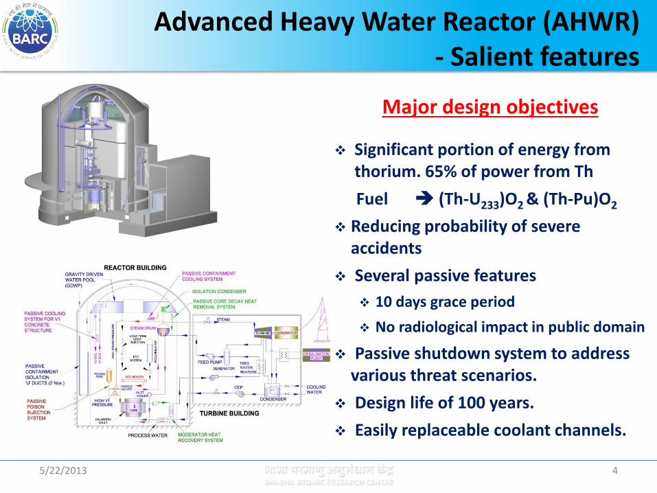
Major design objectives
Significant portion of energy from thorium. 65% of power from Th
Fuel (Th-U233)O2 & (Th-Pu)O2
Reducing probability of severe accidents
Several passive features
10 days grace period
No radiological impact in public domain
Passive shutdown system to address various threat scenarios.
Design life of 100 years.
Easily replaceable coolant channels.
5/22/2013 5
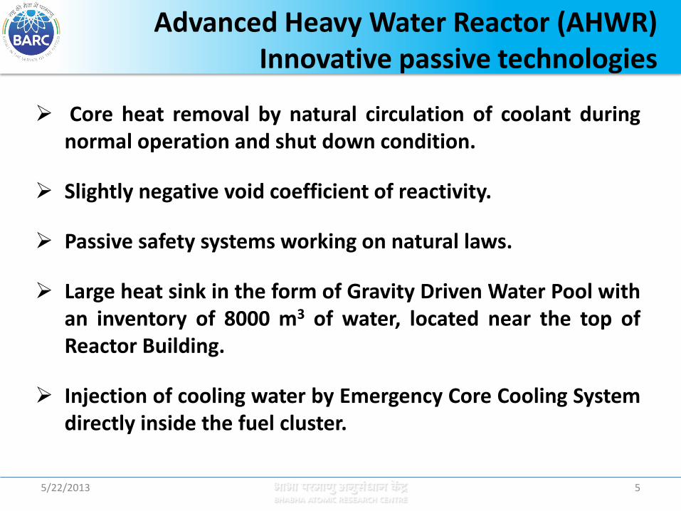
Advanced Heavy Water Reactor (AHWR) Innovative passive technologies
Core heat removal by natural circulation of coolant during normal operation and shut down condition.
Slightly negative void coefficient of reactivity.
Passive safety systems working on natural laws.
Large heat sink in the form of Gravity Driven Water Pool with an inventory of 8000 m3 of water, located near the top of Reactor Building.
Injection of cooling water by Emergency Core Cooling System directly inside the fuel cluster.

5/22/2013 6
Advanced Heavy Water Reactor (AHWR) Innovative passive technologies
Containment cooling by passive containment coolers.
Passive containment isolation by water seal during LOCA.
Two independent shutdown systems (primary and secondary).
Passive poison injection in moderator in the event of non-availability of both primary as well as secondary shut down system due to failure or malevolent insider action.
Facilitate siting close to population centers.

5/22/2013 7
Defence in Depth (IAEA-TECDOC-1434) → 1. Prevention of abnormal operation and failures
Enhance prevention by increased emphasis on inherently safe design characteristics and passive safety features, and by further reducing human actions in the routine operation of the plant.
→ 2. Control of abnormal operation and detection of failures
Give priority to advanced control and monitoring systems with enhanced reliability, intelligence and the ability to anticipate and compensate abnormal transients.
→ 3. Control of accidents within the design basis
Optimized combination of active & passive design features; limit consequences such as fuel failures; large heat sinks within/ around containment, minimize reliance on human intervention by increasing grace period, e.g. between several hours and several days.
Safety Criteria for Innovative Advanced Reactor Designs

5/22/2013 8
Defence in Depth (IAEA-TECDOC-1434)
→ 4. Control of severe plant conditions, including prevention and mitigation of the consequences of severe accidents.
Increase reliability and capability of systems to control and monitor complex accident sequences; decrease expected frequency of severe plant conditions; e.g. for reactors, reduce severe core damage frequency by at least one order of magnitude relative to existing plants and designs, and even more for urban-sited facilities.
→ 5. Mitigation of radiological consequences of significant releases of radioactive materials
Avoid the necessity for evacuation or relocation measures outside the plant site.
More independence of levels from each other.
Safety Criteria for Innovative Advanced Reactor Designs

9
Defence-In-Depth (DID) of AHWR
• Level 1 DID: – Elimination of the hazard of loss of coolant flow :
• Heat removal from the core under both normal full power operating condition as well as shutdown condition is by natural circulation of coolant.
– Reduction of the extent of overpower transient : • Slightly negative void co-efficient of reactivity. • Low core power density. • Negative fuel temperature coefficient of reactivity. • Low excess reactivity
• Level 2 DID: – Control of abnormal operation and detection of failure
• An increased reliability of the control system achieved with the use of high reliability digital control using advanced information technology.
• Increased operator reliability achieved with the use of advanced displays and diagnostics using artificial intelligence and expert systems.
• Large coolant inventory in the main coolant system.
10
Passive Systems in Defence-In-Depth of AHWR
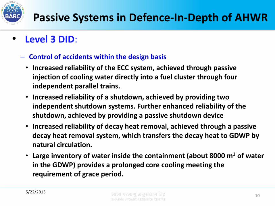
• Level 3 DID:
– Control of accidents within the design basis
• Increased reliability of the ECC system, achieved through passive injection of cooling water directly into a fuel cluster through four independent parallel trains.
• Increased reliability of a shutdown, achieved by providing two independent shutdown systems. Further enhanced reliability of the shutdown, achieved by providing a passive shutdown device
• Increased reliability of decay heat removal, achieved through a passive decay heat removal system, which transfers the decay heat to GDWP by natural circulation.
• Large inventory of water inside the containment (about 8000 m3 of water in the GDWP) provides a prolonged core cooling meeting the requirement of grace period.
5/22/2013
Passive Systems in Defence-In-Depth of AHWR
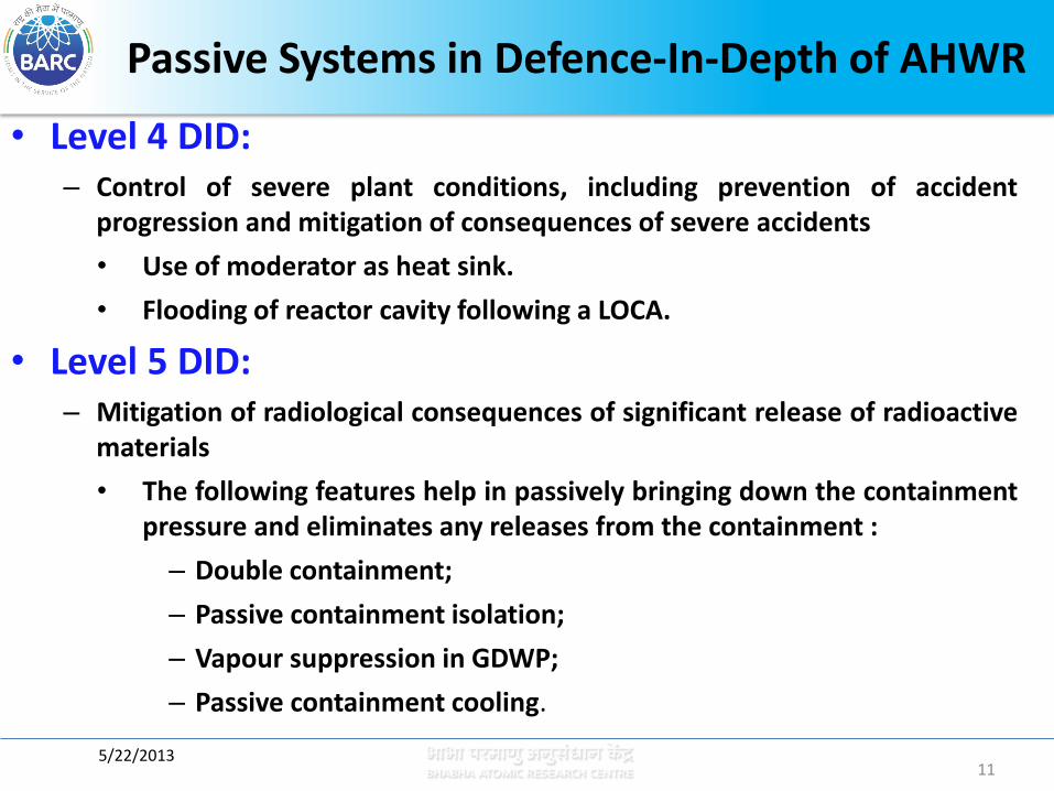
• Level 4 DID: – Control of severe plant conditions, including prevention of accident
progression and mitigation of consequences of severe accidents
• Use of moderator as heat sink.
• Flooding of reactor cavity following a LOCA.
• Level 5 DID: – Mitigation of radiological consequences of significant release of radioactive
materials
• The following features help in passively bringing down the containment pressure and eliminates any releases from the containment :
– Double containment;
– Passive containment isolation;
– Vapour suppression in GDWP;
– Passive containment cooling.
11 5/22/2013

Heat removal from core under both normal full power operating condition as well as shutdown condition is by natural circulation of coolant.
Some important passive safety features of
AHWR –1/4
12 5/22/2013
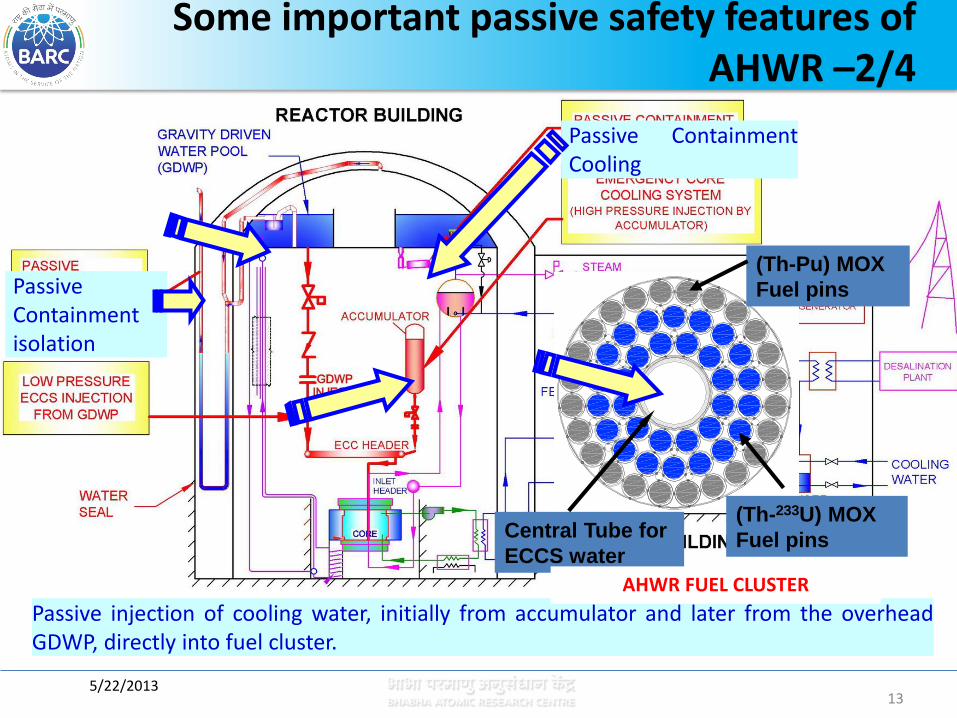
Passive injection of cooling water, initially from accumulator and later from the overhead GDWP, directly into fuel cluster.
(Th-Pu) MOX
Fuel pins
(Th-233U) MOX
Fuel pins Central Tube for
ECCS water
AHWR FUEL CLUSTER
Passive Containment isolation
Passive Containment Cooling
Some important passive safety features of
AHWR –2/4
13 5/22/2013

14
Some important passive safety features of AHWR –3/4
Passive Poison Injection System actuates during very low probability event of failure of wired shutdown systems (SDS#1 & SDS#2) and non-availability of Main condenser
Passive Poison Injection in moderator during overpressure transient
Some important passive safety features of AHWR –3/4

Use of moderator as heat sink Water in
calandria vault
Flooding of reactor cavity following LOCA
Some important passive safety features of AHWR –4/4
15 5/22/2013

AHWR- Main Heat Transport System (MHT)
5/22/2013 16
Design Parameters
Common Inlet header 1
No of Feeders/ Channels 452
No of Steam Drum 4
No of Tail pipes connected to each steam drum. 113
No of Down comers from each steam drum connected to common inlet header 4
Fuel Burn Up 34,000 Mwd/Te
Core Flow rate 2,306 Kg/Sec
Coolant inlet temp 261.4 ºC
Feed water temp 130 ºC
Average Quality 17.6%
Steam Pressure & Temp 70 bar & 285 ºC

AHWR- I&C Architecture
5/22/2013 17
Regulation of reactor power and process variables of the plant within limits
Control and monitoring of
* Main Heat Transport System and auxiliary process systems
* Turbine and turbine auxiliary systems
* Generator and its auxiliary systems
* Electrical systems
* Station common process and service systems
Ensuring safety of the plant under all operating conditions and during all postulated emergency situations and
Sensing accident conditions and initiating the operation of systems required to mitigate the consequences of such accidents.
I & C systems of AHWR are designed to carry out the following important parameters
Based on their functions C&I systems are classified as safety systems (IA), safety related systems (IB)and systems not important to nuclear safety (NINS).
AHWR- I&C Architecture
5/22/2013 18
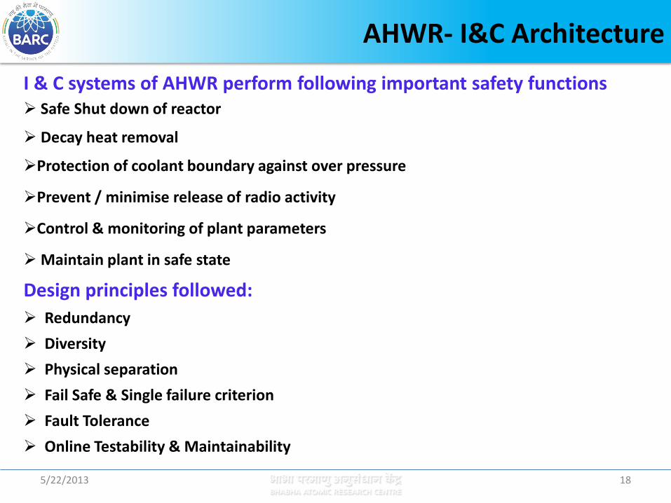
Safe Shut down of reactor
Decay heat removal
Protection of coolant boundary against over pressure
Prevent / minimise release of radio activity
Control & monitoring of plant parameters
Maintain plant in safe state
I & C systems of AHWR perform following important safety functions
Design principles followed:
Redundancy
Diversity
Physical separation
Fail Safe & Single failure criterion
Fault Tolerance
Online Testability & Maintainability

AHWR- I&C Architecture
5/22/2013 19
Group-1 - SDS-1 - ECCS - CLMS-BSF - Plant systems for normal operation & safety related control systems
Two- Group Philosophy:
To enhance the Reliability, I&C systems are divided into two groups namely Group-1 & Group-2
Each group has the capability to perform the safety functions independent of the systems in other group
I&C hardware are independent with respect to sensors, power supplies, cables and are physically separated
Functional independence of the two groups ensure single local event (Fire or Pipe failure etc) will not result in multiple component or system failure
Group-2
- SDS-II - CIS

AHWR- Technological Challenges
5/22/2013 20
Block Diagram Of C&I Architecture of AHWR
AHWR- I&C Architecture
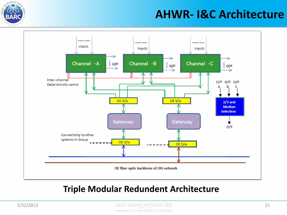
5/22/2013 21
Triple Modular Redundent Architecture
AHWR- I&C Architecture
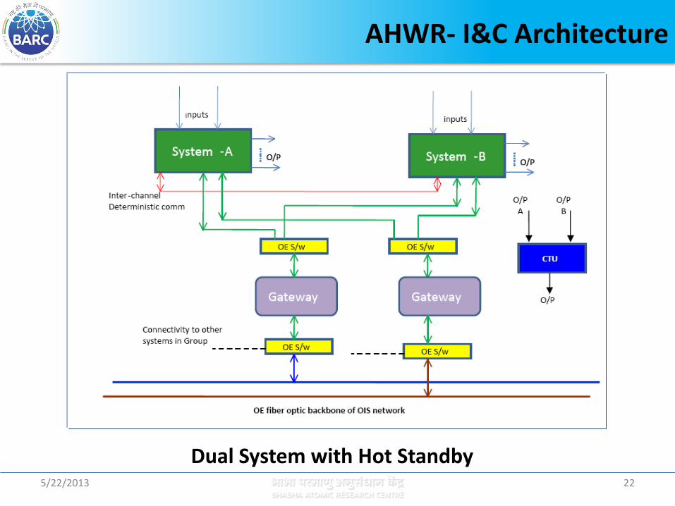
5/22/2013 22
Dual System with Hot Standby

AHWR- Technological Challenges
5/22/2013 23
The technological challenges in AHWR are
To design and develop novel devices suitable for precision measurement of bi-directional low velocity flow in feeders and identify the flow reversal in the channels
To develop sensors for void measurements and an algorithm to compute channel quality and hence the channel power from this void fraction
To identify the occurrence of stagnation channel break
Trip the reactor if any of these parameters exceeds the safe limit.
The main design requirement of AHWR is to maintain adequate thermal and stability margin. Instability and Critical Heat Flux (CHF) in the system should be avoided in the operation under all operational states and transients. Hence the channel flow and channel power monitoring instrumentation becomes very important for channel safety and integrity.

AHWR-R&D and Experimentation
5/22/2013 24
Development of Instrumentation sensors and methods and their qualification in experimental facilities simulating AHWR operating conditions were taken up for
The measurement of low velocity Bi-directional flow
void fraction
Two-phase flow
Measurement technique for channel power

Development of Bi-directional venturi for AHWR
Channel Flow Measurement
Channel flow monitoring instrumentation is very important in
AHWR for channel safety & Integrity
Requirements: To measure low flow velocities
Minimum permanent pressure loss
To identify flow reversal
Flow measurement in high temperature and high pressure natural circulation system
Channel flow measurement in all 452 inlet feeder lines
to monitor
1) Fwd flow during reactor normal operation
2) Rev flow during (for eg: refuelling/ defuelling, Feeder LOCA)
5/22/2013 25

The objective is to provide the novel device suitable for precision measurement of bi-directional low velocity flow and identify the flow reversal when fluid is at high temperature and high pressure AHWR operating condition.
Design Basis:
Why Venturi flow element?
Minimum permanent pressure loss (since pressure loss affects Natural Circulation flow).
Minimum straight lengths requirement.
Bi-directional flow measurement is feasible by selecting same convergence and divergence angles.
Development of Bi-directional venturi for AHWR
Channel Flow Measurement
26 5/22/2013

Design Of Bidirectional Venturi
DP1 DP2
P1 P2 P3
DP1 = P1 - P2 DP2 = P3 - P2
D = Pipe diameter, m
d = throat diameter, m
= beta ratio of Bidirectional Venturi
= Venturi discharge coefficient
= Differential pressure pa
= Density of water in
= Flow rate in
dC
p
Q 3mkg
sm3
Schematic of Bidirectional venturi, beta = 0.5
27 5/22/2013

BIDIRECTIONAL VENTURI FLOWMETER
Low permanent head loss
Good measurement sensitivity at low flow velocities
Reasonably constant discharge co-
efficient for wide range of Reynolds numbers
Flow reversal identification
Bidirectional Venturi
Salient features: Bi-directional flow measurement
Accuracy better than ± 0.5% (Calibrated at room temperatures and the characteristics are stored for better accuracy)
Sensor shall introduce least disturbance in the process
28 5/22/2013
For orifice, venturi and nozzle design, empirical standards such as BS1042 is used.
For Bidirectional venturi design, no such standard is available.
Hence systematic design approach for dimensional optimization by theoretical modeling and simulation studies using Computational fluid dynamic (CFD) code were taken up.
Experimental & CFD Results were compared
Bidirectional Venturi
29 5/22/2013
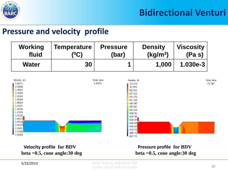
Pressure and velocity profile
Working
fluid
Temperature
(0C)
Pressure
(bar)
Density
(kg/m3)
Viscosity
(Pa s)
Water 30 1 1,000 1.030e-3
Velocity profile for BDV
beta =0.5, cone angle:30 deg
Pressure profile for BDV
beta =0.5, cone angle:30 deg
Bidirectional Venturi
30 5/22/2013
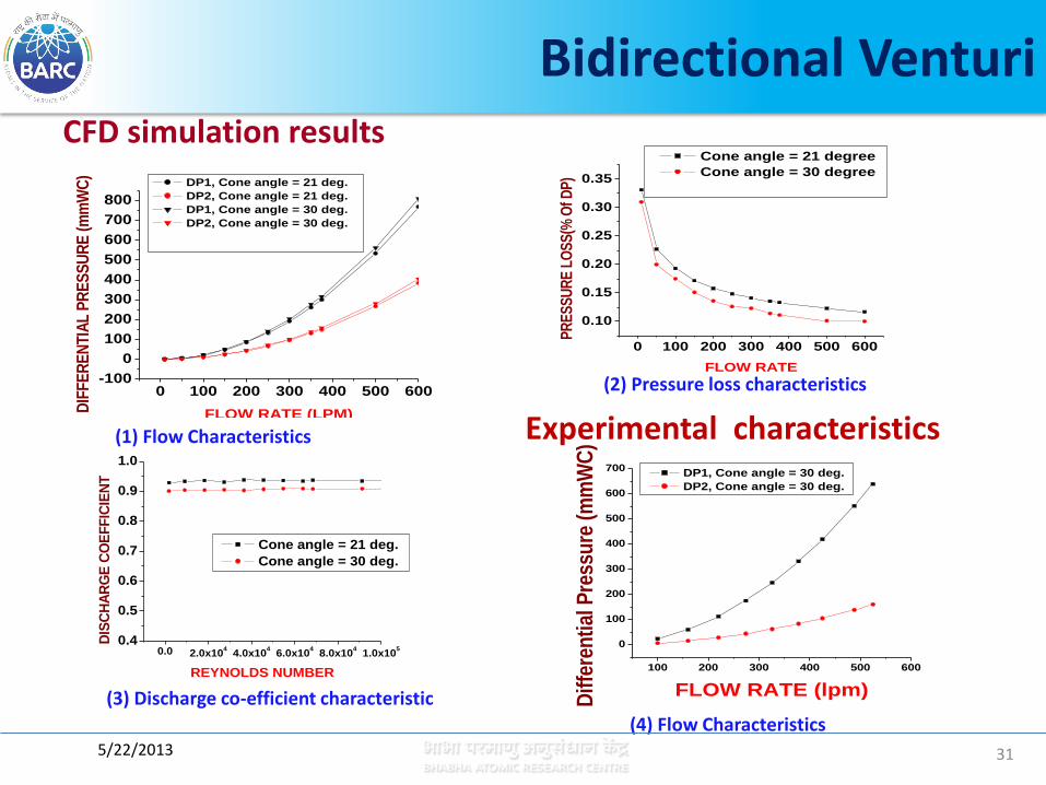
CFD simulation results
0 100 200 300 400 500 600-100
0
100
200
300
400
500
600
700
800
DIF
FE
RE
NT
IAL
PR
ES
SU
RE
(m
mW
C)
FLOW RATE (LPM)
DP1, Cone angle = 21 deg.
DP2, Cone angle = 21 deg.
DP1, Cone angle = 30 deg.
DP2, Cone angle = 30 deg.
0 100 200 300 400 500 600
0.10
0.15
0.20
0.25
0.30
0.35
PR
ES
SU
RE
LO
SS
(% O
f DP
)
FLOW RATE
Cone angle = 21 degree
Cone angle = 30 degree
0.0 2.0x10⁴
4.0x10⁴
6.0x10⁴
8.0x10⁴
1.0x10⁵
0.4
0.5
0.6
0.7
0.8
0.9
1.0
DIS
CH
AR
GE
CO
EF
FIC
IEN
T
REYNOLDS NUMBER
Cone angle = 21 deg.
Cone angle = 30 deg.
Bidirectional Venturi
(2) Pressure loss characteristics
(1) Flow Characteristics
(3) Discharge co-efficient characteristic
100 200 300 400 500 600
0
100
200
300
400
500
600
700
Dif
fere
nti
al P
ress
ure
(m
mW
C)
FLOW RATE (lpm)
DP1, Cone angle = 30 deg.
DP2, Cone angle = 30 deg.
Experimental characteristics
(4) Flow Characteristics
31 5/22/2013
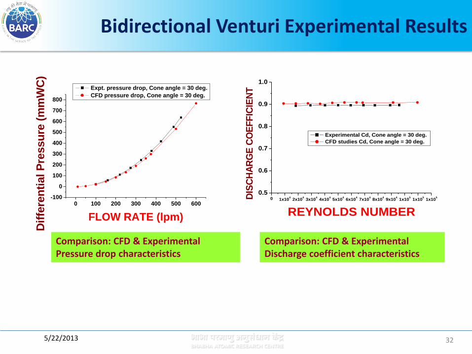
Bidirectional Venturi Experimental Results
0 100 200 300 400 500 600-100
0
100
200
300
400
500
600
700
800
Dif
fere
nti
al P
ressu
re (
mm
WC
)
FLOW RATE (lpm)
Expt. pressure drop, Cone angle = 30 deg.
CFD pressure drop, Cone angle = 30 deg.
0 1x10⁴
2x10⁴
3x10⁴
4x10⁴
5x10⁴
6x10⁴
7x10⁴
8x10⁴
9x10⁴
1x10⁵
1x10⁵
1x10⁵
0.5
0.6
0.7
0.8
0.9
1.0
DIS
CH
AR
GE
CO
EF
FIC
IEN
T
REYNOLDS NUMBER
Experimental Cd, Cone angle = 30 deg.
CFD studies Cd, Cone angle = 30 deg.
Comparison: CFD & Experimental Pressure drop characteristics
Comparison: CFD & Experimental Discharge coefficient characteristics
32 5/22/2013
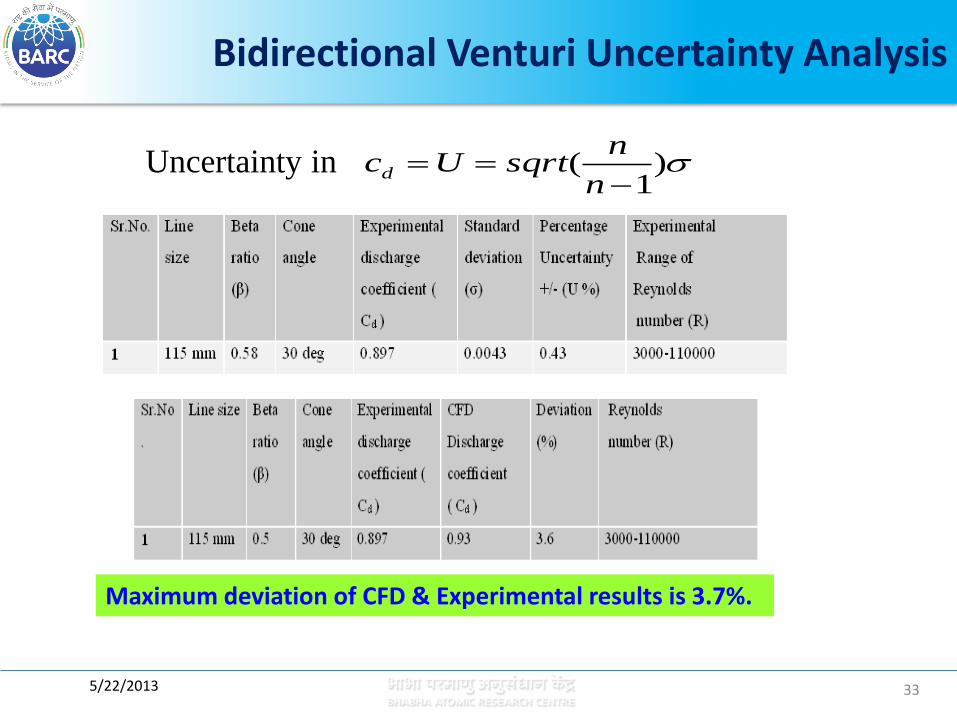
Uncertainty in )1
(
n
nsqrtUcd
Bidirectional Venturi Uncertainty Analysis
Maximum deviation of CFD & Experimental results is 3.7%.
33 5/22/2013
Development of Two-phase Flow Instrumentation
5/22/2013 34
Measurement of two-phase flow in steam-water natural circulation system is complex and various attempts were made to understand and develop instrumentation so that channel power can be obtained for effective channel monitoring.
OBJECTIVE:
Design and Development of Two-Phase Flow Sensor for High Pressure Steam-Water Applications
1. Impedance based void sensor (Rotating Electric field Admittance probe)
2. Two-phase mass flux measurements by pitot tubes
assembly and Gamma Ray Densitometer

Rotating Electric Field Admittance Probe
5/22/2013 35
Methodology :
Mixture impedance relative to that of the separate phases gives
void fraction.
Transit time of random flow fluctuations to travel between
adjacent sensors can determine the fluid phase velocities.
Basic principle of measurement: The basic principle of the sensor developed is based on the difference in electrical properties between the liquid and vapor phases, the total admittance i.e. capacitance and resistance relative to that of the separate phases gives void fraction.
)( j
mixmixmixeYj CGY
Rotating Electric Field Admittance Probe
5/22/2013 36
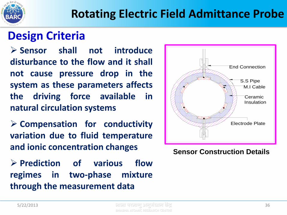
Sensor shall not introduce disturbance to the flow and it shall not cause pressure drop in the system as these parameters affects the driving force available in natural circulation systems
Compensation for conductivity variation due to fluid temperature and ionic concentration changes
Prediction of various flow regimes in two-phase mixture through the measurement data
End Connection
S.S Pipe
M.I Cable
Ceramic
Insulation
Electrode Plate
Sensor Construction Details
Design Criteria

Rotating Electric Field Admittance Probe
5/22/2013 37
The electrodes are mounted coaxially inside to form part of pipe wall to eliminate the disturbance to the flow.
The sensor causes no pressure drop in the system.
The electric field which is perpendicular to the flow is rotated electronically to distribute it through out the sensor volume.
The conductivity changes due to temperature and ion concentration are compensated by measuring relative admittance w.r.t. reference sensor located in single phase region.
The phase shift of sensor signal with respect to excitation voltage determines flow regimes.
Salient features :
5/22/2013 38
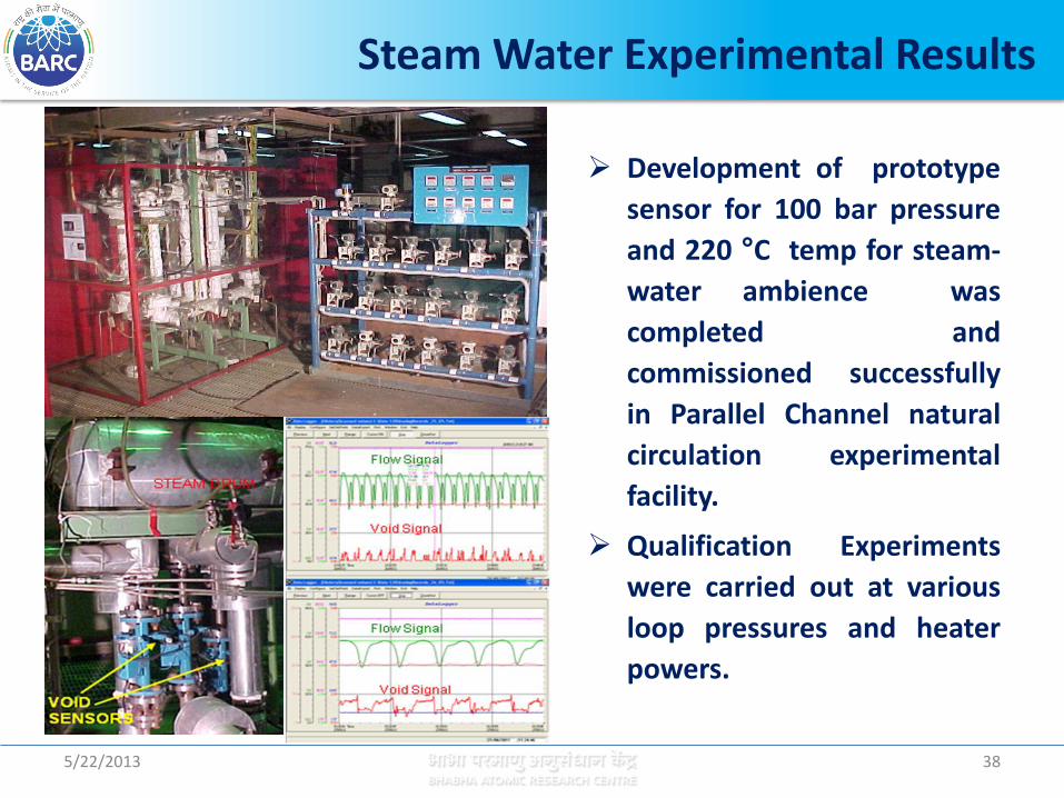
Steam Water Experimental Results
Development of prototype
sensor for 100 bar pressure
and 220 °C temp for steam-
water ambience was
completed and
commissioned successfully
in Parallel Channel natural
circulation experimental
facility.
Qualification Experiments
were carried out at various
loop pressures and heater
powers.
Rotating Electric Field Admittance Probe
Uncertainty Analysis
• Uncertainty was estimated for a set of Air-Water experimental data and analysed for the various flow regimes using data obtained from the air-water visual experiments by signature analysis.
• Uncertainty was found to be within 3 to 9% for the various flow regimes from bubbly to churn flow upto 80% void fraction.
Advantages :
• Simple data interpretation for real time measurements.
• Fast response, hence can be used for transient studies.
• Volume average technique for better results.
• Provides flow pattern discrimination.
5/22/2013 39

Two Phase Mass Flux Measurement by Pitot Tubes assembly and Traversing Gamma Ray Densitometer
Methodology
Cross section averaged Two Phase mass velocity measurements using
• Pitot Tubes assembly
Chordal void fraction and average mixture density measurements using
• Traversing Gamma Ray Densitometer
5/22/2013 40

High Pressure Natural Circulation Loop (HPNCL)
Heater
Gamma Source
Gamma Detector
Water
Steam + water
Condenser Steam Drum
Two Phase Mass Flux Measurement by Pitot Tubes assembly and Traversing Gamma Ray Densitometer
Pitot tubes assembly
Gammm ray densitometer
Pitot Tubes assembly & Gamma ray densitometer in Experimental set up
Pitot Tubes Assembly
5/22/2013 41
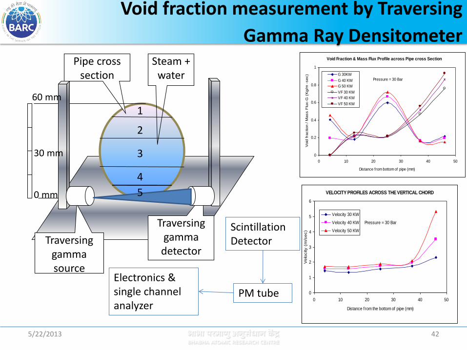
1
2
3
4
5
Steam + water
Pipe cross section
0 mm
30 mm
60 mm
Scintillation Detector
PM tube
Electronics & single channel analyzer
Traversing gamma source
Traversing gamma detector
1
2
3
4
5
Void fraction measurement by Traversing
Gamma Ray Densitometer
5/22/2013 42
Void Fraction & Mass Flux Profile across Pipe cross Section
0
0.2
0.4
0.6
0.8
1
0 10 20 30 40 50
Distance from bottom of pipe (mm)
Void
fra
ction / M
ass F
lux-G
(K
g/m
-sec) G 30KW
G 40 KW
G 50 KW
VF 30 KW
VF 40 KW
VF 50 KW
Pressure = 30 Bar
VELOCITY PROFILES ACROSS THE VERTICAL CHORD
0
1
2
3
4
5
6
0 10 20 30 40 50
Distance from the bottom of pipe (mm)V
elo
city (
m/s
ec)
Velocity 30 KW
Velocity 40 KW
Velocity 50 KW
Pressure = 30 Bar

Rugged, simple, reliable and easy to operate
The data interpretation is simple.
Sturdy sensor for adverse high temperature
and high pressure steam water applications.
Introduces only very little disturbance in low path, which is very important for two phase natural circulation studies.
Advantages
Two Phase Mass Flux Measurement by Pitot Tubes assembly and Traversing Gamma Ray Densitometer
5/22/2013 43

44
Integral Test Loop (ITL) for Experimental Demonstration
44
ITL is a scaled facility which simulates the MHT, ECCS, IC System along with the associated controls of the AHWR
The integral or global scaling is based on the power-to-volume scaling philosophy.
All these sensors namely bi-directional venturi, rotating electric field admittance probe and multi beam gamma ray densitometer are planned to be installed in this facility for experimental qualification under reactor operating process conditions.
BDV Installed in ITL
5/22/2013

45
Technique for Channel Power Measurement
45 5/22/2013
Algorithm evolved for channel power computation using two-phase pressure drop measurements in the vertical tail pipes of AHWR.
The pressure drop (P) measured in the vertical tail pipes be considered to be comprising of gravitational pressure drop component only
The measured P used to obtain the density of the steam water mixture coming out of fuel channels and in turn void fraction in the pipe section. Steam quality then obtained in each channel using appropriate experimentally verified correlation.
Power in channel estimated using the measured channel mass flow rate and channel inlet/outlet enthalpy.
The uncertainty in measurements will be established through detailed experimentation.

46
Channel stagnation break identification
46 5/22/2013
In Natural circulation based Boiling Water Reactors small break LOCA detection is important.
Single channel event which is of concern for safety in these pressure tube type reactors is, stagnation channel break which is typically a small inlet feeder break of specific size.
The consequences such as fuel over heating in that channel can be avoided if there is a trip on channel low flow.
Since flow trip in all 452 channels is difficult, detection of steam leak is essential to detect this LOCA of various sizes.
47
Channel stagnation break identification
47 5/22/2013
For prompt action on post small break LOCA, steam leak detection system is developed to detect any leak inside the reactor vault.
To identify this channel stagnation break occurrence, acoustic sensors are provided in the reactor vault.
The outputs of these sensors are analyzed for noise level and spectrum characteristics to detect the steam leakage.
The detection technique is reliable and plays a very important role in ensuring safety of the reactor.
Reactor Trip
The signals from these acoustic sensors, flow measurements in inlet feeders and void fraction measurements in tail pipes generate reactor trip signal.

48 48 5/22/2013
Concluding Remarks
The technical challenges in I&C measurements for pressure tube type AHWR and general I&C architecture addressed.
The channel flow, channel power and channel stagnation break identification - important monitoring instrumentation for channel safety.
All the 452 channels in AHWR are instrumented with in-house developed bi-directional venturi flow meters for monitoring the forward flow and identify flow reversal if any during defueling/refueling.
The in-house developments of sensors for void fraction measurement are taken up and their qualification in high temperature, high pressure R&D experimental facility is in progress.
The channel power measurement technique was evolved and is monitored in all 452 channels.
A robust technique of steam leak detection is developed by acoustics method for channel stagnation break identification.

5/22/2013 49