Embed Size (px)
Citation preview
11th World Congress on Structural and Multidisciplinary Optimisation 07th -12th, June 2015, Sydney Australia
1
Form finding by shape optimization with the Vertex Morphing Method – About the equivalence of sensitivity filtering and standard spline models
Kai-Uwe Bletzinger, Majid Hojjat, Electra Stavropoulou
Technische Universität München, Germany, [email protected]
1. Abstract The proper parameterization of structural shape which is suitable for creating structural form and shape optimal design is a great challenge. The demand for large design spaces with large and very large numbers of design parameters is in conflict with the robustness of the numerical model. There is a need for regularization. The currently most successful techniques which overcome those burdens and, simultaneously, are most intuitive and easy to be used are so-called filter techniques. They directly use the coordinates of the discretization nodes as design parameters. Filters are applied to smooth the shape sensitivity fields as the generator of the design update towards the optimum. However, the filters are much more than mathematical means to prevent numerical problems such as mesh distortion or checker board patterns. Even more important, from the point of view of shape design they deal as a design tool to controlling the local and global shape properties. The actual presentation will show that filtering is equivalent to the implicit definition of standard spline models. Impressive applications in the fields of CSD and CFD with problem sizes up to 3.5 million design parameters can easily be handled by this technique. 2. Keywords: Shape optimization, sensitivity filtering, morphing, structural optimization, CFD optimization 3. Introduction Sensitivity filtering is a well-established and very successful procedure in discrete topology and shape optimization. It is used to regularize the optimization problem by introducing an additional filter length scale which is independent of the discretization. The filter is both, a design tool controlling local shape or density distribution and a mean to prevent numerical problems such as mesh distortion or checker board patterns. Together with adjoint sensitivity analysis to determine the discretized shape gradient, the filter technique is a most powerful optimization procedure and successively applied to the largest optimization problems known. Filtering is the key technology for using the vertices of even the finest discretization mesh directly as design handles for discrete shape optimization. In contrast to standard shape morphing techniques and CAD methodologies no other design handles are used. Among those techniques which do not use CAD parameters to parameterize shape there are meshfree and node-based or parameter-free methods which means “free of CAGD parameters” (Le et al. 2011; Scherer et al. 2010; Hojjat et al. 2014), the traction method (Azegami and Takeuchi 2006), for CFD problems (Pironneau 1984; Jameson 1995, 2000, 2003; Mohammadi and Pironneau 2000, 2004; Stück and Rung 2011). 4. Continuous Shape control by using filters We start by introducing an additional field p. This serves as the control which steers the evolution of shape. In analogy to splines the control field can be identified as the continuous equivalent to the convex hull which is discretized by control nodes. As with splines where the coordinates of the control nodes are the design variables, now, the control field represents the design degrees of freedom which drive the shape. The considered shape optimization problem states as:
( ) ( )( )( )
( ) ( )( )( )
( ) ( )( )( ) m...,,1j;0p,xz,xu,p,xz,xg
0p,xz,xu,p,xz,x:.t.s
p,xz,xu,p,xz,xfmin
j =≤
=Rp
(1)
where f and gj are the objective function and constraints and R are the state equations which may be non-linear. There are four fields describing the state u, the surface coordinate x, the geometry z as well as the design control field p, Fig. 1. For the sake of simplicity, (1) is formulated in 1D geometric space. As a consequence, the geometry z is a function of the one spatial surface coordinate x and the design control p. Extended to 3D, (1) represents the classical view at a surface controlled shape optimization problem following the ideas of Hadamard. Then, the shape relevant modifications of geometry z are identified as in the normal direction to the surface spanned by
2
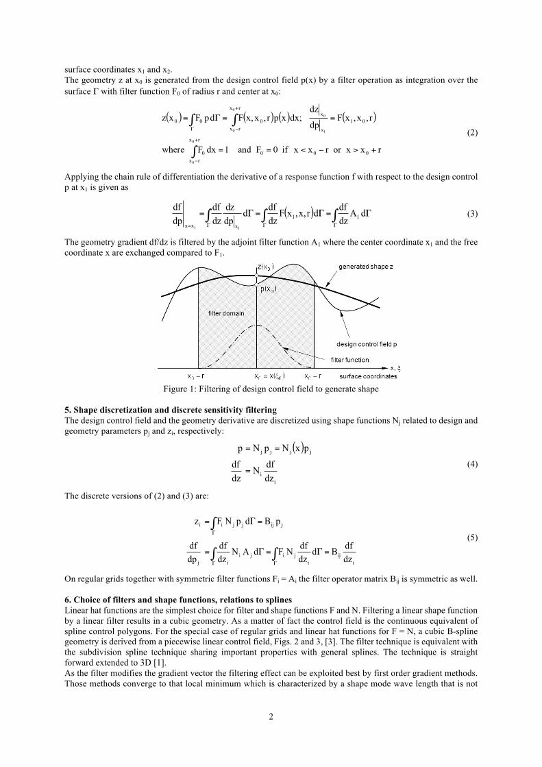
surface coordinates x1 and x2. The geometry z at x0 is generated from the design control field p(x) by a filter operation as integration over the surface Γ with filter function F0 of radius r and center at x0:
( ) ( ) ( ) ( )
rxxorrxxif0Fand1dxFwhere
r,x,xFdp
dz;dxxpr,x,xFdpFxz
000
rx
rx0
01x
xrx
rx000
0
0
1
00
0
+>−<==
==Γ=
∫
∫∫+
−
+
−Γ (2)
Applying the chain rule of differentiation the derivative of a response function f with respect to the design control p at x1 is given as
( ) ∫∫∫ΓΓΓ=
Γ=Γ=Γ= dAdzdfdr,x,xF
dzdfd
dpdz
dzdf
dpdf
11xxx 11
(3)
The geometry gradient df/dz is filtered by the adjoint filter function A1 where the center coordinate x1 and the free coordinate x are exchanged compared to F1.
Figure 1: Filtering of design control field to generate shape
5. Shape discretization and discrete sensitivity filtering The design control field and the geometry derivative are discretized using shape functions Nj related to design and geometry parameters pj and zi, respectively:
( )
ii
jjjj
dzdfN
dzdf
pxNpNp
=
==
(4)
The discrete versions of (2) and (3) are:
iij
ijiji
ij
jijjjii
dzdfBd
dzdfNFdAN
dzdf
dpdf
pBdpNFz
=Γ=Γ=
=Γ=
∫∫
∫
ΓΓ
Γ (5)
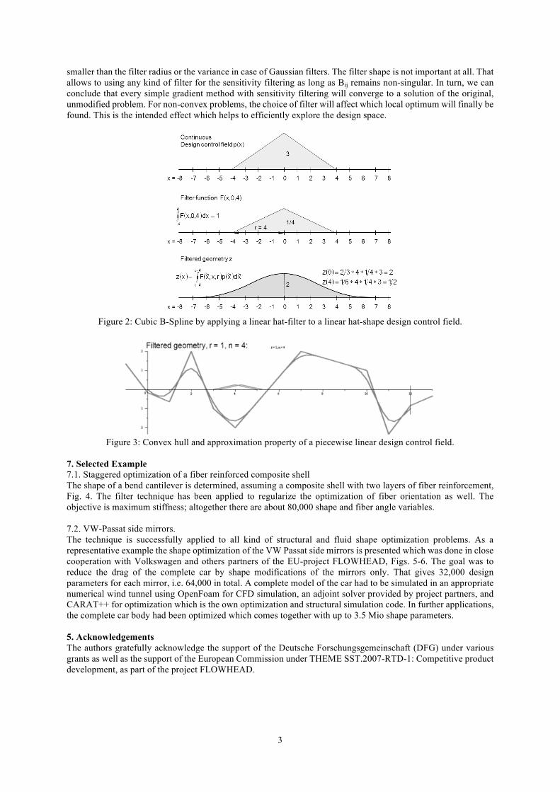
On regular grids together with symmetric filter functions Fi = Ai the filter operator matrix Bij is symmetric as well. 6. Choice of filters and shape functions, relations to splines Linear hat functions are the simplest choice for filter and shape functions F and N. Filtering a linear shape function by a linear filter results in a cubic geometry. As a matter of fact the control field is the continuous equivalent of spline control polygons. For the special case of regular grids and linear hat functions for F = N, a cubic B-spline geometry is derived from a piecewise linear control field, Figs. 2 and 3, [3]. The filter technique is equivalent with the subdivision spline technique sharing important properties with general splines. The technique is straight forward extended to 3D [1]. As the filter modifies the gradient vector the filtering effect can be exploited best by first order gradient methods. Those methods converge to that local minimum which is characterized by a shape mode wave length that is not
3
smaller than the filter radius or the variance in case of Gaussian filters. The filter shape is not important at all. That allows to using any kind of filter for the sensitivity filtering as long as Bij remains non-singular. In turn, we can conclude that every simple gradient method with sensitivity filtering will converge to a solution of the original, unmodified problem. For non-convex problems, the choice of filter will affect which local optimum will finally be found. This is the intended effect which helps to efficiently explore the design space.
Figure 2: Cubic B-Spline by applying a linear hat-filter to a linear hat-shape design control field.
Figure 3: Convex hull and approximation property of a piecewise linear design control field.
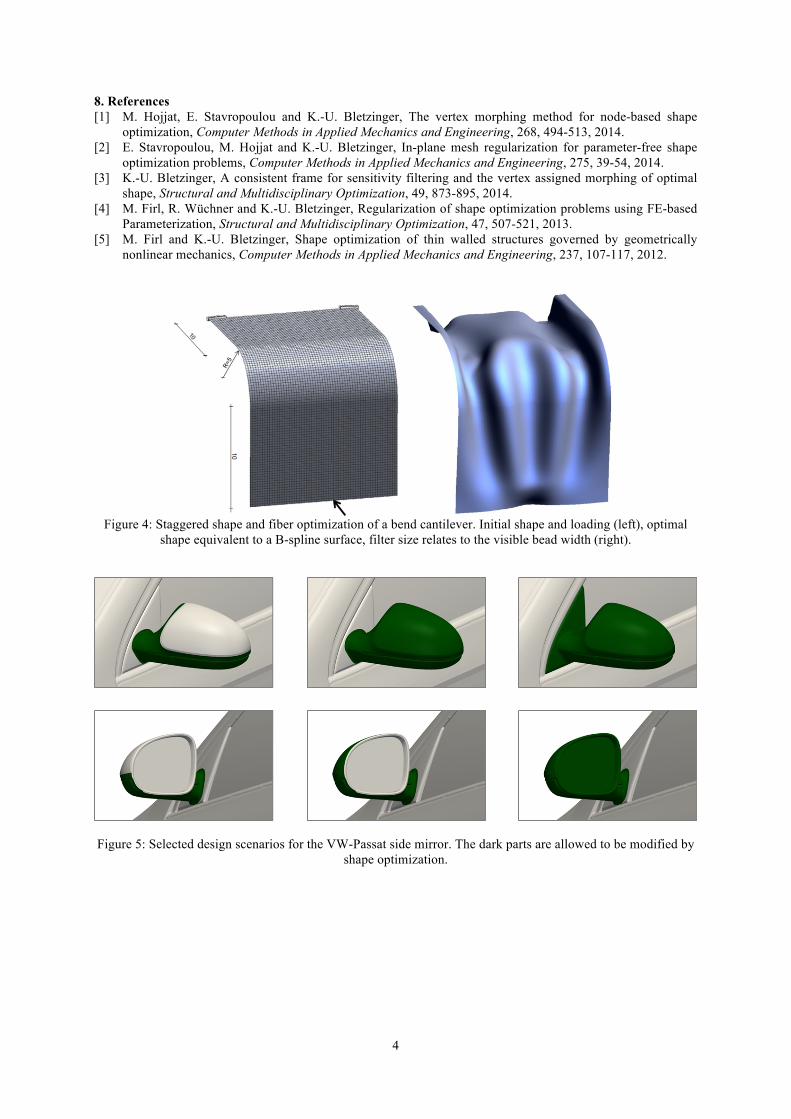
7. Selected Example 7.1. Staggered optimization of a fiber reinforced composite shell The shape of a bend cantilever is determined, assuming a composite shell with two layers of fiber reinforcement, Fig. 4. The filter technique has been applied to regularize the optimization of fiber orientation as well. The objective is maximum stiffness; altogether there are about 80,000 shape and fiber angle variables. 7.2. VW-Passat side mirrors. The technique is successfully applied to all kind of structural and fluid shape optimization problems. As a representative example the shape optimization of the VW Passat side mirrors is presented which was done in close cooperation with Volkswagen and others partners of the EU-project FLOWHEAD, Figs. 5-6. The goal was to reduce the drag of the complete car by shape modifications of the mirrors only. That gives 32,000 design parameters for each mirror, i.e. 64,000 in total. A complete model of the car had to be simulated in an appropriate numerical wind tunnel using OpenFoam for CFD simulation, an adjoint solver provided by project partners, and CARAT++ for optimization which is the own optimization and structural simulation code. In further applications, the complete car body had been optimized which comes together with up to 3.5 Mio shape parameters. 5. Acknowledgements The authors gratefully acknowledge the support of the Deutsche Forschungsgemeinschaft (DFG) under various grants as well as the support of the European Commission under THEME SST.2007-RTD-1: Competitive product development, as part of the project FLOWHEAD.
4
8. References [1] M. Hojjat, E. Stavropoulou and K.-U. Bletzinger, The vertex morphing method for node-based shape
optimization, Computer Methods in Applied Mechanics and Engineering, 268, 494-513, 2014. [2] E. Stavropoulou, M. Hojjat and K.-U. Bletzinger, In-plane mesh regularization for parameter-free shape
optimization problems, Computer Methods in Applied Mechanics and Engineering, 275, 39-54, 2014. [3] K.-U. Bletzinger, A consistent frame for sensitivity filtering and the vertex assigned morphing of optimal
shape, Structural and Multidisciplinary Optimization, 49, 873-895, 2014. [4] M. Firl, R. Wüchner and K.-U. Bletzinger, Regularization of shape optimization problems using FE-based
Parameterization, Structural and Multidisciplinary Optimization, 47, 507-521, 2013. [5] M. Firl and K.-U. Bletzinger, Shape optimization of thin walled structures governed by geometrically
nonlinear mechanics, Computer Methods in Applied Mechanics and Engineering, 237, 107-117, 2012.
Figure 4: Staggered shape and fiber optimization of a bend cantilever. Initial shape and loading (left), optimal
shape equivalent to a B-spline surface, filter size relates to the visible bead width (right).
Figure 5: Selected design scenarios for the VW-Passat side mirror. The dark parts are allowed to be modified by shape optimization.
5
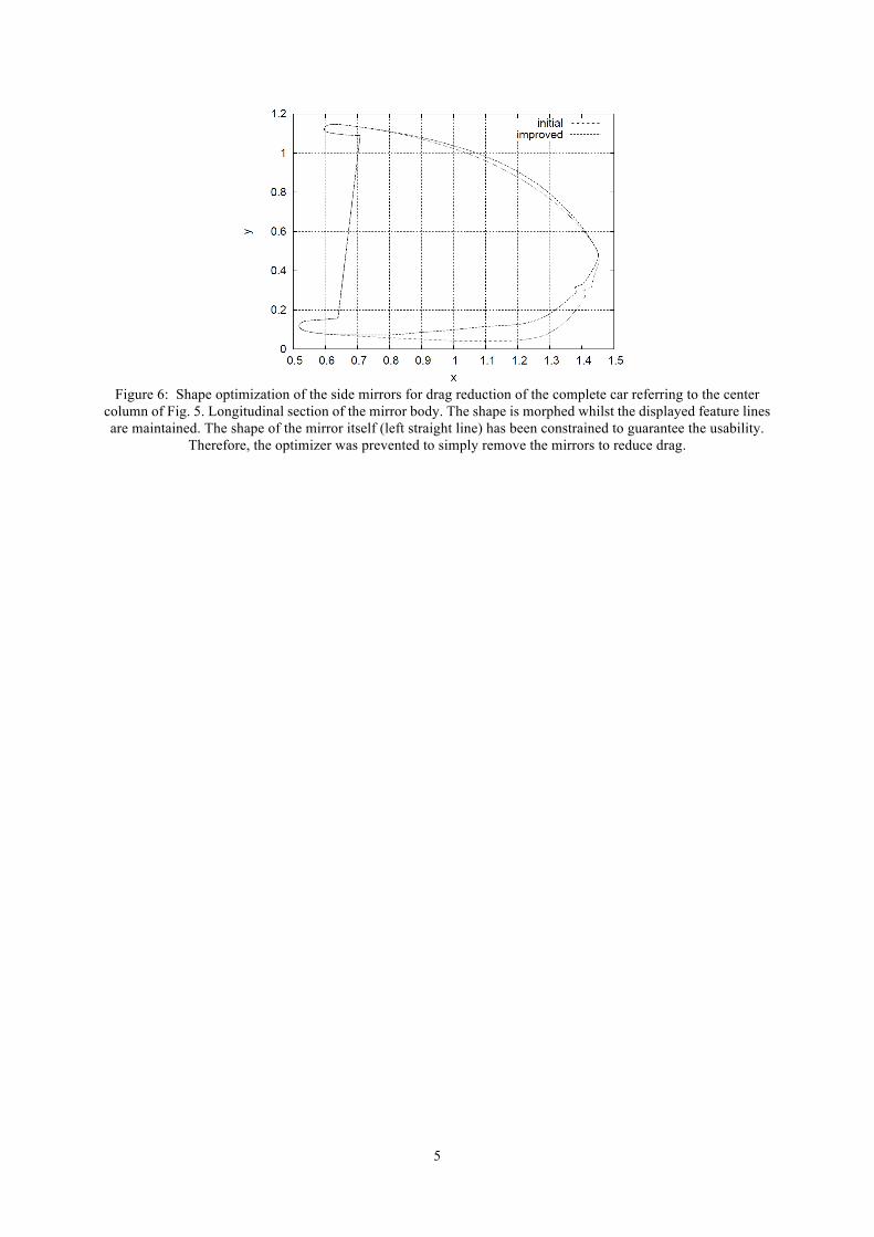
Figure 6: Shape optimization of the side mirrors for drag reduction of the complete car referring to the center
column of Fig. 5. Longitudinal section of the mirror body. The shape is morphed whilst the displayed feature lines are maintained. The shape of the mirror itself (left straight line) has been constrained to guarantee the usability.
Therefore, the optimizer was prevented to simply remove the mirrors to reduce drag.


![› fileadmin › produkte › prozesssicherheit › IG-KUB-PTU › Product... PRE-TORQUE MULTIFLANGE RUPTURE DISC HOLDER IG-KUB …Technical data NPS [in] DN [mm] Pressure class ANSI](https://img.pdfslide.us/doc/110x75/5e5c81b2e284b369207b1909/a-fileadmin-a-produkte-a-prozesssicherheit-a-ig-kub-ptu-a-product-pre-torque.jpg)

![Smart Way to Handle the Air - GEOVENT · 39-123 Box fan KUB 80-500 EC 39-124 Box fan KUB 80-560 EC 39-125 Box fan KUB 80-630 EC 39-126 Box fan KUB 100-630 EC 100 1.200 Air Flow [m³/h]](https://img.pdfslide.us/doc/110x75/5eb3221fa2dcab0e5c5b909e/smart-way-to-handle-the-air-geovent-39-123-box-fan-kub-80-500-ec-39-124-box-fan.jpg)