Embed Size (px)
Citation preview

Technische DokumentationTechnical DocumentationDocumentation Technique
VIBROCONTROL 920
C006590.01

All rights reservedNo part of this technical documentation may be reproducedwithout prior written permission of Brüel & Kjær Vibro GmbH.
Subject to change without prior notice.
Copyright 2001 by Brüel & Kjær Vibro GmbH, D-64273 Darmstadt
Contents VIBROCONTROL 920
Contents 1 General.......................................................................................... 3
1.1 OK Monitoring.................................................................................................4
1.2 VIBROCONTROL 920 operation after switch-on or power return..................4
2 Technical Data .............................................................................. 5
3 Display and operating elements .................................................... 9
3.1 Button: MODE.................................................................................................9
3.2 Measured Value / Parameter ..........................................................................9
3.3 Display period .................................................................................................9
3.4 Status signals................................................................................................10
3.5 Reset ............................................................................................................11
3.6 Store .............................................................................................................11
4 Internal Tests and Error Signals.................................................. 13
4.1 Test of the LED display and alarm LEDs ......................................................13
4.2 Displaying the program version.....................................................................13
4.3 Displaying the calibration constants..............................................................13
4.4 Error messages.............................................................................................13
© VC920E August 2004 Valid as from device No. 0022ED6I Page 1 of 32
VIBROCONTROL 920 Contents
5 Setups ......................................................................................... 15
5.1 Function: Displaying parameters...................................................................15
5.2 Function: Changing parameter values ..........................................................16
5.3 Parameter: Group 1 ......................................................................................17
5.4 Parameter: Group 2 ......................................................................................19
5.5 Parameter: Group 3 Service Parameter........................................................22
6 Mounting and Installation ............................................................ 23
6.1 Mounting and Installation Instructions...........................................................23
6.2 Connecting Cable shields (*1) .......................................................................24
6.3 Shield earth (*2).............................................................................................24
6.4 Mounting .......................................................................................................25
7 Wiring diagrams .......................................................................... 27
8 Service ........................................................................................ 32
9 Instrument versions ..................................................................... 33
10 Parameter list .............................................................................. 34
Page 2 of 32 © VC920E August 2004 Valid as from device No. 0022ED6I
General VIBROCONTROL 920
VIBROCONTROL 920
VIBROCONTROL 920
24V
0 - 10V
LIM 2
COM
LIM 1
21
MODE
3 4
18
+ Ic
17
- DC
19 20
SIG
(mm/s)rms5 6
V
7
OK +
8 9 10
21 22 23
B
24 25 26
+
LIM 1
115
RESET
PE- L
1211 13
115 / 230 V AC
230 115
N
1514 16
LIM 2
2827 29
+
0/4 - 20mA
OK
3130 32
REL.RESET
VC920 (030224)
Brüel & Kjær Vibro
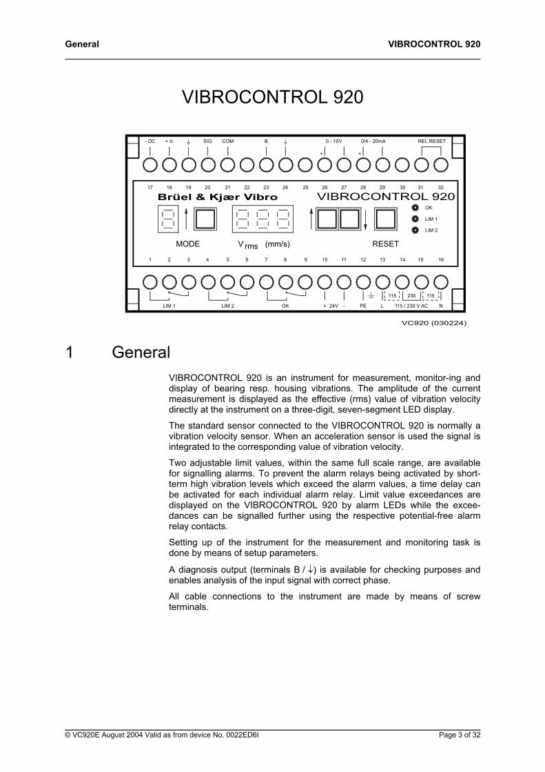
1 General VIBROCONTROL 920 is an instrument for measurement, monitor-ing and display of bearing resp. housing vibrations. The amplitude of the current measurement is displayed as the effective (rms) value of vibration velocity directly at the instrument on a three-digit, seven-segment LED display.
The standard sensor connected to the VIBROCONTROL 920 is normally a vibration velocity sensor. When an acceleration sensor is used the signal is integrated to the corresponding value of vibration velocity.
Two adjustable limit values, within the same full scale range, are available for signalling alarms. To prevent the alarm relays being activated by short-term high vibration levels which exceed the alarm values, a time delay can be activated for each individual alarm relay. Limit value exceedances are displayed on the VIBROCONTROL 920 by alarm LEDs while the excee-dances can be signalled further using the respective potential-free alarm relay contacts.
Setting up of the instrument for the measurement and monitoring task is done by means of setup parameters.
A diagnosis output (terminals B / ↓) is available for checking purposes and enables analysis of the input signal with correct phase.
All cable connections to the instrument are made by means of screw terminals.
© VC920E August 2004 Valid as from device No. 0022ED6I Page 3 of 32
VIBROCONTROL 920 General
1.1 OK Monitoring Self-monitoring of the power supply, the internal microprocessor system as well as the sensor status is done by the OK monitoring system.
An existing OK error is displayed by an LED and signalled by the change-over of potential-free contacts of the OK relay. In the case of a fault the light-emitting diode will go off and the contacts of the corresponding relay will change over.
1.2 VIBROCONTROL 920 operation after switch-on or power return
The instrument automatically executes a self-test lasting approxi-mately 6 secs. each time it is switched on. Through this a cali-bration constant for the measuring circuit is determined which is then calculated into the results of all future measurements. During this self-test phase the status of the OK and limit relays is retained as defined for an error-free condition.
After completion of the self-test the instrument switches to the monitoring operation. After this time any exceedances of the pre-defined limit and calibration values lead to corresponding event signals.
Page 4 of 32 © VC920E August 2004 Valid as from device No. 0022ED6I
Technical Data VIBROCONTROL 920
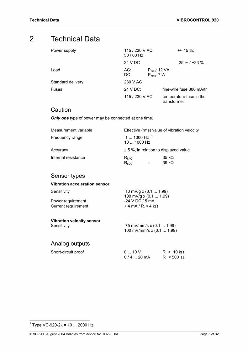
2 Technical Data Power supply 115 / 230 V AC +/- 15 %; 50 / 60 Hz
24 V DC -25 % / +33 %
Load AC: Pmax: 12 VA DC: Pmax: 7 W
Standard delivery 230 V AC
Fuses 24 V DC: fine-wire fuse 300 mA/tr
115 / 230 V AC: temperature fuse in the transformer
Caution Only one type of power may be connected at one time.
Measurement variable Effective (rms) value of vibration velocity
Frequency range 1 ... 1000 Hz 1 10 ... 1000 Hz
Accuracy ± 5 %, in relation to displayed value
Internal resistance Ri AC = 35 kΩ Ri DC = 39 kΩ
Sensor types Vibration acceleration sensor
Sensitivity 10 mV/g x (0.1 ... 1.99) 100 mV/g x (0.1 ... 1.99) Power requirement -24 V DC / 5 mA Current requirement + 4 mA / Ri < 4 kΩ
Vibration velocity sensor Sensitivity 75 mV/mm/s x (0.1 ... 1.99) 100 mV/mm/s x (0.1 ... 1.99)
Analog outputs Short-circuit proof 0 ... 10 V RL > 10 kΩ 0 / 4 ... 20 mA RL < 500 Ω
1 Type VC-920-2k = 10 ... 2000 Hz © VC920E August 2004 Valid as from device No. 0022ED6I Page 5 of 32
VIBROCONTROL 920 Technical Data
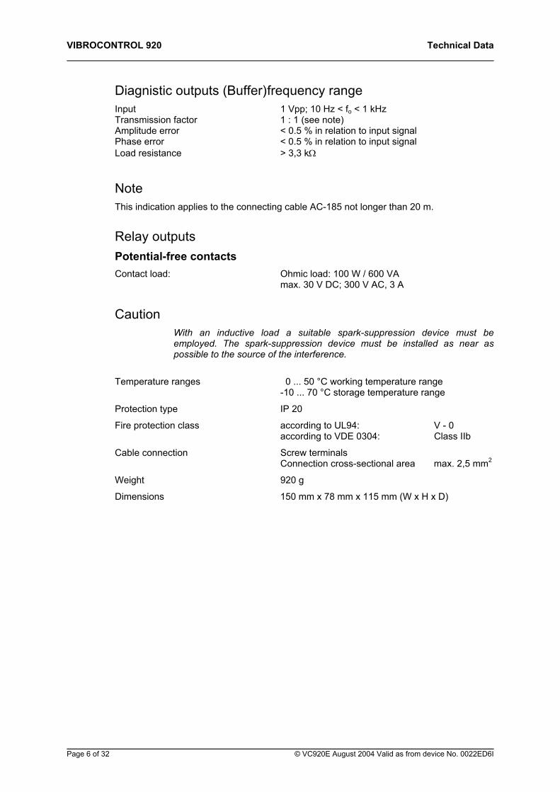
Diagnistic outputs (Buffer) frequency range Input 1 Vpp; 10 Hz < fo < 1 kHz Transmission factor 1 : 1 (see note) Amplitude error < 0.5 % in relation to input signal Phase error < 0.5 % in relation to input signal Load resistance > 3,3 kΩ
Note This indication applies to the connecting cable AC-185 not longer than 20 m.
Relay outputs Potential-free contacts Contact load: Ohmic load: 100 W / 600 VA max. 30 V DC; 300 V AC, 3 A
Caution With an inductive load a suitable spark-suppression device must be employed. The spark-suppression device must be installed as near as possible to the source of the interference.
Temperature ranges 0 ... 50 °C working temperature range -10 ... 70 °C storage temperature range
Protection type IP 20
Fire protection class according to UL94: V - 0 according to VDE 0304: Class IIb
Cable connection Screw terminals Connection cross-sectional area max. 2,5 mm2
Weight 920 g
Dimensions 150 mm x 78 mm x 115 mm (W x H x D)
Page 6 of 32 © VC920E August 2004 Valid as from device No. 0022ED6I
Technical Data VIBROCONTROL 920
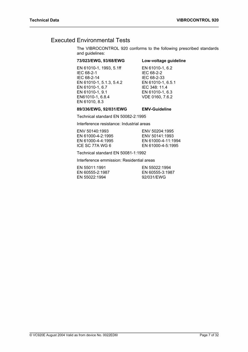
Executed Environmental Tests The VIBROCONTROL 920 conforms to the following prescribed standards and guidelines:
73/023/EWG, 93/68/EWG Low-voltage guideline
EN 61010-1, 1993, 5.1ff EN 61010-1, 6.2 IEC 68-2-1 IEC 68-2-2 IEC 68-2-14 IEC 68-2-33 EN 61010-1, 5.1.3, 5.4.2 EN 61010-1, 6.5.1 EN 61010-1, 6.7 IEC 348: 11.4 EN 61010-1, 9.1 EN 61010-1, 6.3 EN61010-1, 6.8.4 VDE 0160, 7.6.2 EN 61010, 8.3
89/336/EWG, 92/031/EWG EMV-Guideline
Technical standard EN 50082-2:1995
Interference resistance: Industrial areas
ENV 50140:1993 ENV 50204:1995 EN 61000-4-2:1995 ENV 50141:1993 EN 61000-4-4:1995 EN 61000-4-11:1994 ICE SC 77A WG 6 EN 61000-4-5:1995
Technical standard EN 50081-1:1992
Interference emmission: Residential areas
EN 55011:1991 EN 55022:1994 EN 60555-2:1987 EN 60555-3:1987 EN 55022:1994 92/031/EWG
© VC920E August 2004 Valid as from device No. 0022ED6I Page 7 of 32
VIBROCONTROL 920 Technical Data
Safety category according to EN-954-1 • Safety category B (Sk B) according to EN-954-1
• Safety category 1 (Sk 1) according to EN-954-1 under the following conditions:
• If the system is used for applications requiring safety functions of the vibration monitoring system according to safety category 1, the relays have to be used in a closed circuit system.
• The OK-relay has to be integrated into the safety chain in a way that the safety function is activated as soon as the relay responds.
• All adjusting devices have to be protected in a way that they cannot be unintentionally misadjusted during operation. This can be done for instance by mounting the adjusting device in a closed housing resp. switch cabinet. Any opening of the housing/switch cabinet resp. changing of system parameters may only be done by duly trained, authorized staff and has to be documented.
Page 8 of 32 © VC920E August 2004 Valid as from device No. 0022ED6I
Display and operating elements VIBROCONTROL 920
3 Display and operating elements
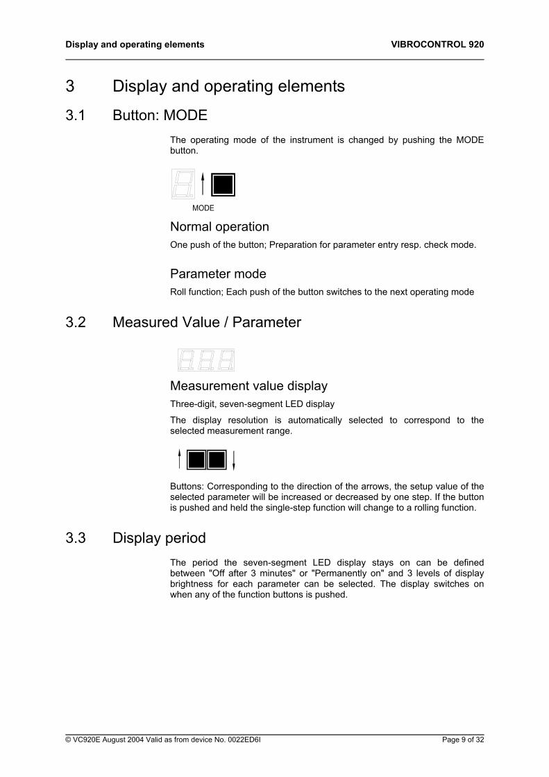
3.1 Button: MODE The operating mode of the instrument is changed by pushing the MODE button.
MODE
Normal operation One push of the button; Preparation for parameter entry resp. check mode.
Parameter mode Roll function; Each push of the button switches to the next operating mode
3.2 Measured Value / Parameter
Measurement value display Three-digit, seven-segment LED display
The display resolution is automatically selected to correspond to the selected measurement range.
Buttons: Corresponding to the direction of the arrows, the setup value of the selected parameter will be increased or decreased by one step. If the button is pushed and held the single-step function will change to a rolling function.
3.3 Display period The period the seven-segment LED display stays on can be defined between "Off after 3 minutes" or "Permanently on" and 3 levels of display brightness for each parameter can be selected. The display switches on when any of the function buttons is pushed.
© VC920E August 2004 Valid as from device No. 0022ED6I Page 9 of 32
VIBROCONTROL 920 Display and operating elements
3.4 Status signals
OK error Green LED / OK relay
The occurrence of an OK error is signalled by the LED lighting up and the OK relay de-energizing.
LIM 1, LIM 2 error signals The behaviour of the limit relays is determined by the connection status of the terminals 31/32 (Relay Reset).
Terminals 31/32 not connected resp. Contacts open
Limit value exceedances are stored - the limit relays remain energized - until the Reset button is pushed. A reset of the limit relay is only possible if the measurement value is lower than the corres-ponding limit value.
Terminals 31/32 connected by push-button
The energized limit relay contacts will be reset. A reset of the limit relay is only possible if the measurement value is lower than the corresponding limit value.
Terminals 31/32 permanently connected (Standard delivery)
The limit exceeedance is signalled only for as long as the limit value is exceeded. If the measurement values fall lower than the limit values the LIM LEDs and the limit relays will be reset.
Limit value LIM 1 Yellow LED / LIM 1 Relay
If the current measurement value is higher than the limit value and remains at this level for longer than the set time delay, the LED will light up. The LIM 1 relay will react according to the defined setup. It will be energized when set up as normally de-energized and will be de-energized when set up as a normally energized relay.
If an OK error occurs during a LIM1 activation, the limit signal (LED and relay) will be reset to the normal status for the duration of the OK error.
Page 10 of 32 © VC920E August 2004 Valid as from device No. 0022ED6I
Display and operating elements VIBROCONTROL 920
Limit value LIM 2 Red LED / LIM 2 Relay
If the current measurement value is higher than the limit value and remains at this level for longer than the set time delay, the LED will light up. The LIM 2 relay will react according to the defined setup. It will be energized when set up as normally de-energized and will be de-energized when set up as a normally energized relay.
If an OK error occurs during a LIM2 activation, the limit signal (LED and relay) will be reset to the normal status for the duration of the OK error.
3.5 Reset
RESET
Normal operation Reset the event signal as well as the associated relay.
The "REL.RESET" terminals have no function in connection with an OK error.
Parameter mode Leave the parameter setup mode. Changes to the parameter values are not activated.
3.6 Store
MODE RESET
Push Mode and Reset simultaneously:
Leave the parameter setup mode. Changes to the parameter values are activated.
© VC920E August 2004 Valid as from device No. 0022ED6I Page 11 of 32
VIBROCONTROL 920 Display and operating elements
This page is for your notes.
Page 12 of 32 © VC920E August 2004 Valid as from device No. 0022ED6I
Internal Tests and Error Signals VIBROCONTROL 920
4 Internal Tests and Error Signals After switching the instrument on a number of tests are executed. If the result of the test reveals an error in the operation of the instrument, this is displayed on the measurement value field in the form of an error message.
4.1 Test of the LED display and alarm LEDs The LED seven-segment displays are checked by displaying the figure 8, and the associated decimal points are switched on. The alarm LEDs light up in the sequence green - yellow - red. This test lasts for approx. 4 seconds.
4.2 Displaying the program version In the mode display field a "v" is displayed and in the measurement value display field the version number is displayed.
4.3 Displaying the calibration constants In the mode display field a "c" is displayed and in the measurement value display field the calibration constants are displayed.
4.4 Error messages The error messages are displayed in the form of an " " followed by a number. The display of the measurement value is overwritten for the duration of the error message. In addition to the visual error signal, an error message is always signalled by activation of the corresponding limit or OK relay.
If the input of the measured value is overmodulated, the dislay shows „ccc„.
© VC920E August 2004 Valid as from device No. 0022ED6I Page 13 of 32
VIBROCONTROL 920 Internal Tests and Error Signals
Error " 01" The value of the calibration constants lies outside the permissible range. A value between 0.5 and 2.0 is permitted. Occurrence of this error means an error in the instrument’s internal acquisition electronics. The instrument should be removed from the monitoring application and returned to the nearest service station for repairs.
Error " 02" The values of the internal voltages lie outside the permissible limits. For a check see Group 3: Parameter 3 (+ 5 V) and Parameter 4 (+ 17 V). Occurrence of this error means an error in the instrument’s power supply. The instrument should be removed from the monitoring application and returned to the nearest service station for repairs.
Error " 03" The temperature inside the instrument housing has exceeded the 90 °C (± 10 %) limit. If this error message occurs the instrument should be removed from the monitoring application and returned to the nearest service station for repairs.
Error " 04" OK-error identification
Always Power failure
Vibration acceleration sensor Cable break Short-circuit between the conductors
Vibration velocity sensor Cable open circuit
In the event of this error the analog output will be switched to 0 volt resp. 0 / 4 mA. The OK LED will go off and the OK relay will de-energize and can only be reset using the RESET button. Until the cause of this error is eliminated the OK error signal will remain.
Error " 05" Failure of the OK monitoring function. This error shows a failure of the OK monitoring function. If this error message occurs the instrument should be removed from the monitoring application and returned to the nearest service station for repairs.
Error " ccc " The measured value input is overmodulated. If the measured value is situated again within the measuring range the error message disapears.
Page 14 of 32 © VC920E August 2004 Valid as from device No. 0022ED6I
Setups VIBROCONTROL 920
5 Setups General
The parameters are divided into three Groups each with respectively seven parameters. The parameters in Groups 1 and 2 are concerned with configuration parameters while those in Group 3 are concerned with service parameters.
Viewing or making changes to parameter values can only be done after first entering a code number associated with the Group. Parameter entries only take effect and are stored after leaving the entry mode, i.e. after simultaneously pushing the MODE + RESET buttons. Changes to the parameters are ignored when the entry mode is exited by pushing the RESET button.
5.1 Function: Displaying parameters
MODE button Push once. The number 1 is displayed in the mode display field.
[ ↑ ] resp. [ ↓ ] buttons Push repeatedly until the desired code number is displayed in the measurement value field.
MODE button The mode selection is accepted. Now the parameter number 2 is displayed and the associated parameter value is displayed in the measurement value field.
MODE button Pushing the MODE button switches to the next parameter.
RESET button Pushing the RESET button exits the display mode. The corresponding value of the input signal is displayed in the measu-rement value field.
© VC920E August 2004 Valid as from device No. 0022ED6I Page 15 of 32
VIBROCONTROL 920 Setups
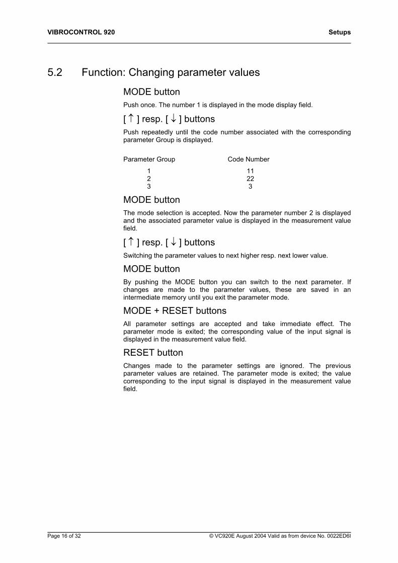
5.2 Function: Changing parameter values
MODE button Push once. The number 1 is displayed in the mode display field.
[ ↑ ] resp. [ ↓ ] buttons Push repeatedly until the code number associated with the corresponding parameter Group is displayed.
Parameter Group Code Number
1 11 2 22 3 3
MODE button The mode selection is accepted. Now the parameter number 2 is displayed and the associated parameter value is displayed in the measurement value field.
[ ↑ ] resp. [ ↓ ] buttons Switching the parameter values to next higher resp. next lower value.
MODE button By pushing the MODE button you can switch to the next parameter. If changes are made to the parameter values, these are saved in an intermediate memory until you exit the parameter mode.
MODE + RESET buttons All parameter settings are accepted and take immediate effect. The parameter mode is exited; the corresponding value of the input signal is displayed in the measurement value field.
RESET button Changes made to the parameter settings are ignored. The previous parameter values are retained. The parameter mode is exited; the value corresponding to the input signal is displayed in the measurement value field.
Page 16 of 32 © VC920E August 2004 Valid as from device No. 0022ED6I
Setups VIBROCONTROL 920
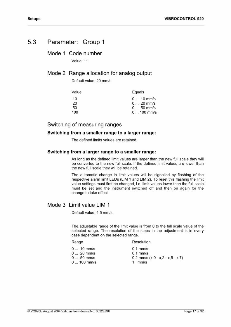
5.3 Parameter: Group 1
Mode 1 Code number Value: 11
Mode 2 Range allocation for analog output Default value: 20 mm/s
Value Equals
10 0 ... 10 mm/s 20 0 ... 20 mm/s 50 0 ... 50 mm/s 100 0 ... 100 mm/s
Switching of measuring ranges Switching from a smaller range to a larger range:
The defined limits values are retained.
Switching from a larger range to a smaller range: As long as the defined limit values are larger than the new full scale they will be converted to the new full scale. If the defined limit values are lower than the new full scale they will be retained.
The automatic change in limit values will be signalled by flashing of the respective alarm limit LEDs (LIM 1 and LIM 2). To reset this flashing the limit value settings must first be changed, i.e. limit values lower than the full scale must be set and the instrument switched off and then on again for the change to take effect.
Mode 3 Limit value LIM 1 Default value: 4.5 mm/s
The adjustable range of the limit value is from 0 to the full scale value of the selected range. The resolution of the steps in the adjustment is in every case dependent on the selected range.
Range Resolution
0 ... 10 mm/s 0,1 mm/s 0 ... 20 mm/s 0,1 mm/s 0 ... 50 mm/s 0,2 mm/s (x,0 - x,2 - x,5 - x,7) 0 ... 100 mm/s 1 mm/s
© VC920E August 2004 Valid as from device No. 0022ED6I Page 17 of 32
VIBROCONTROL 920 Setups
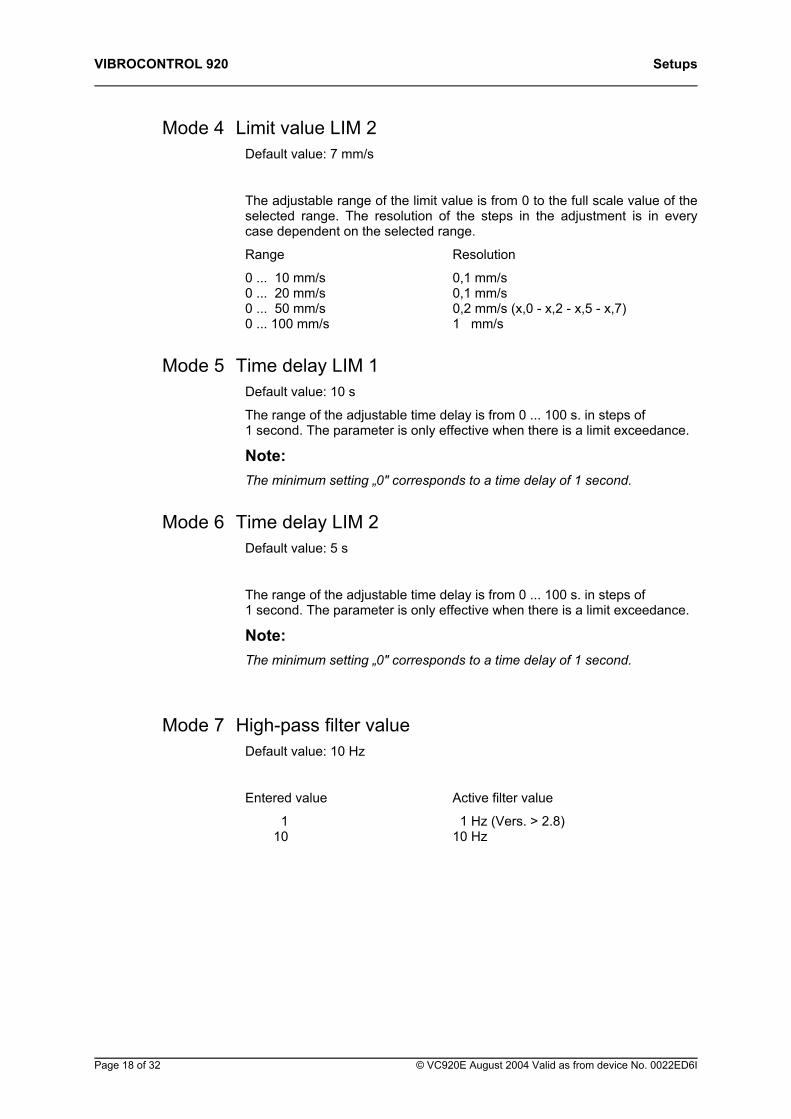
Mode 4 Limit value LIM 2 Default value: 7 mm/s
The adjustable range of the limit value is from 0 to the full scale value of the selected range. The resolution of the steps in the adjustment is in every case dependent on the selected range.
Range Resolution
0 ... 10 mm/s 0,1 mm/s 0 ... 20 mm/s 0,1 mm/s 0 ... 50 mm/s 0,2 mm/s (x,0 - x,2 - x,5 - x,7) 0 ... 100 mm/s 1 mm/s
Mode 5 Time delay LIM 1 Default value: 10 s
The range of the adjustable time delay is from 0 ... 100 s. in steps of 1 second. The parameter is only effective when there is a limit exceedance.
Note: The minimum setting „0" corresponds to a time delay of 1 second.
Mode 6 Time delay LIM 2 Default value: 5 s
The range of the adjustable time delay is from 0 ... 100 s. in steps of 1 second. The parameter is only effective when there is a limit exceedance.
Note: The minimum setting „0" corresponds to a time delay of 1 second.
Mode 7 High-pass filter value Default value: 10 Hz
Entered value Active filter value
1 1 Hz (Vers. > 2.8) 10 10 Hz
Page 18 of 32 © VC920E August 2004 Valid as from device No. 0022ED6I
Setups VIBROCONTROL 920
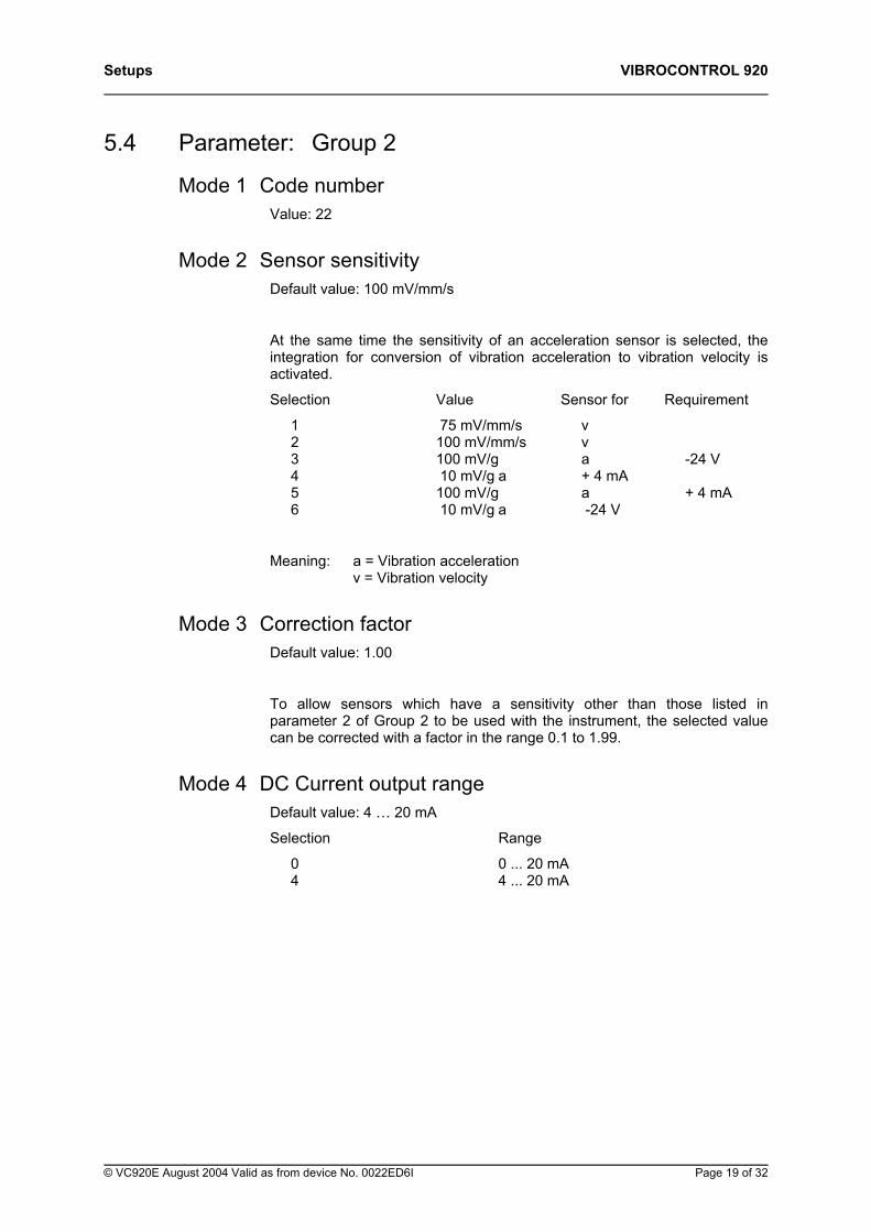
5.4 Parameter: Group 2
Mode 1 Code number Value: 22
Mode 2 Sensor sensitivity Default value: 100 mV/mm/s
At the same time the sensitivity of an acceleration sensor is selected, the integration for conversion of vibration acceleration to vibration velocity is activated.
Selection Value Sensor for Requirement
1 75 mV/mm/s v 2 100 mV/mm/s v 3 100 mV/g a -24 V 4 10 mV/g a + 4 mA 5 100 mV/g a + 4 mA 6 10 mV/g a -24 V
Meaning: a = Vibration acceleration v = Vibration velocity
Mode 3 Correction factor Default value: 1.00
To allow sensors which have a sensitivity other than those listed in parameter 2 of Group 2 to be used with the instrument, the selected value can be corrected with a factor in the range 0.1 to 1.99.
Mode 4 DC Current output range Default value: 4 … 20 mA
Selection Range
0 0 ... 20 mA 4 4 ... 20 mA
© VC920E August 2004 Valid as from device No. 0022ED6I Page 19 of 32
VIBROCONTROL 920 Setups
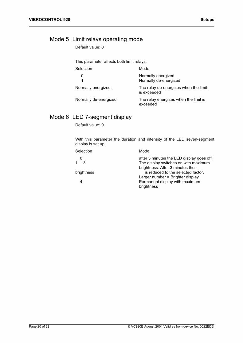
Mode 5 Limit relays operating mode Default value: 0
This parameter affects both limit relays.
Selection Mode
0 Normally energized 1 Normally de-energized
Normally energized: The relay de-energizes when the limit is exceeded
Normally de-energized: The relay energizes when the limit is exceeded
Mode 6 LED 7-segment display Default value: 0
With this parameter the duration and intensity of the LED seven-segment display is set up.
Selection Mode
0 after 3 minutes the LED display goes off. 1 ... 3 The display switches on with maximum brightness. After 3 minutes the brightness is reduced to the selected factor. Larger number = Brighter display 4 Permanent display with maximum brightness
Page 20 of 32 © VC920E August 2004 Valid as from device No. 0022ED6I
Setups VIBROCONTROL 920
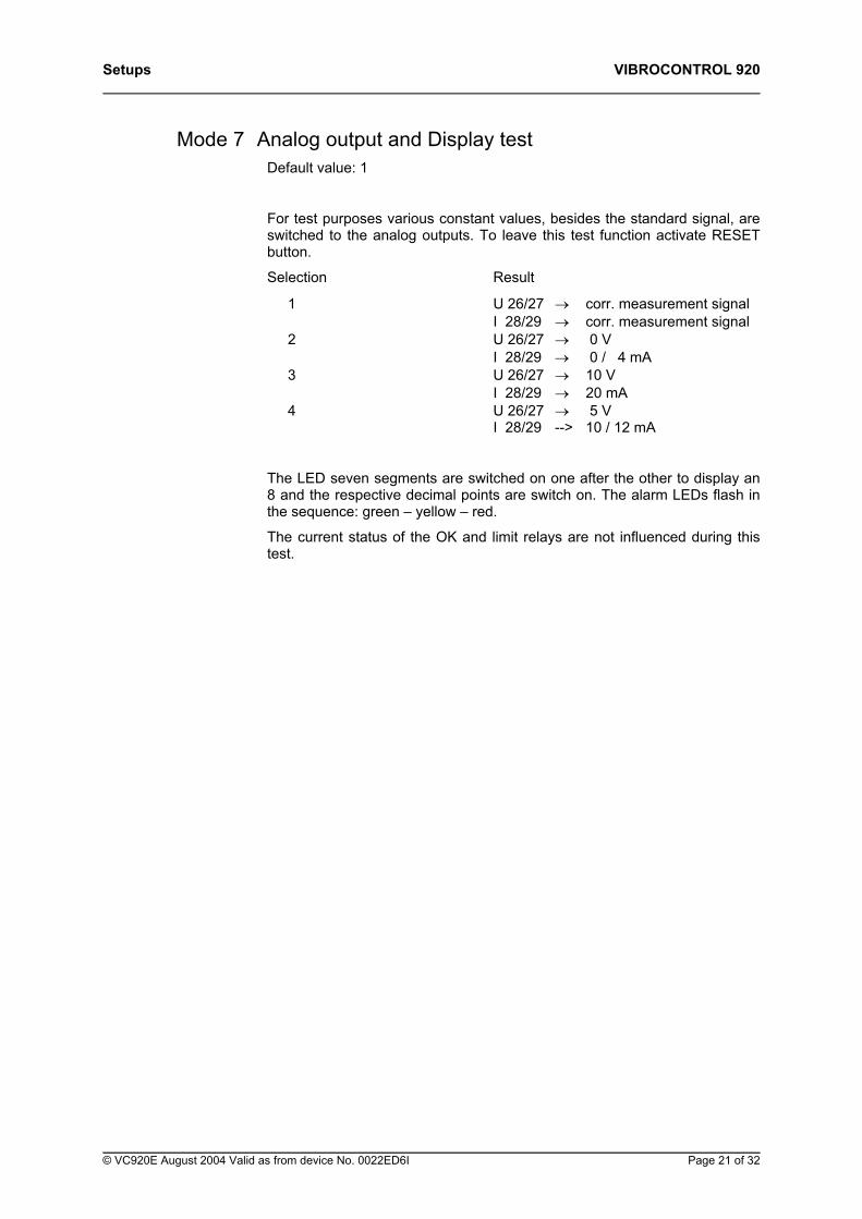
Mode 7 Analog output and Display test Default value: 1
For test purposes various constant values, besides the standard signal, are switched to the analog outputs. To leave this test function activate RESET button.
Selection Result
1 U 26/27 → corr. measurement signal I 28/29 → corr. measurement signal 2 U 26/27 → 0 V I 28/29 → 0 / 4 mA 3 U 26/27 → 10 V I 28/29 → 20 mA 4 U 26/27 → 5 V I 28/29 --> 10 / 12 mA
The LED seven segments are switched on one after the other to display an 8 and the respective decimal points are switch on. The alarm LEDs flash in the sequence: green – yellow – red.
The current status of the OK and limit relays are not influenced during this test.
© VC920E August 2004 Valid as from device No. 0022ED6I Page 21 of 32
VIBROCONTROL 920 Setups
5.5 Parameter: Group 3 Service Parameter
Mode 1 Code number Value: 3
Mode 2 DC rest voltage of the sensor The DC rest voltage of the sensor is displayed. This should be in case of sensors
• type AS–02x between -14 V DC and -10 V DC
• Typ AS-06x bei 12,5 V ± 1,5V supply powered sensors
• type AS-06x (CCS) 13 V DC ± 1,5 V constant-current powered sensors
• type VS-080 0,8 V DC
With more negative voltages the display will flash.
Mode 3 Internal voltage 5 Volt The 5 Volt power for the internal components of the instrument is displayed. The value should be in the range 4.8 V to 5.2 V. Values outside this range lead to the error message ' 02'.
Mode 4 Internal voltage 17 Volt The 17 Volt power for the internal components of the instrument is displayed. The value should be in the range 16.8 V to 19.0 V. Voltage values outside this range will lead to the error message ' 02'.
Mode 5 Housing internal temperature The temperature inside the instrument housing is displayed in °C. If the temperature inside the instrument exceeds the predefined limit the error message ' 03' will be displayed.
Mode 6 Input amplifier amplification factor The current amplification factor of the input amplifier is displayed in steps of 1 - 2 - 4 - 8 - ... 128.
Mode 7 Output of the D/A converter The display range of 0 ... 127 corresponds to 0 ... 20 mA
Page 22 of 32 © VC920E August 2004 Valid as from device No. 0022ED6I
Mounting and Installation VIBROCONTROL 920
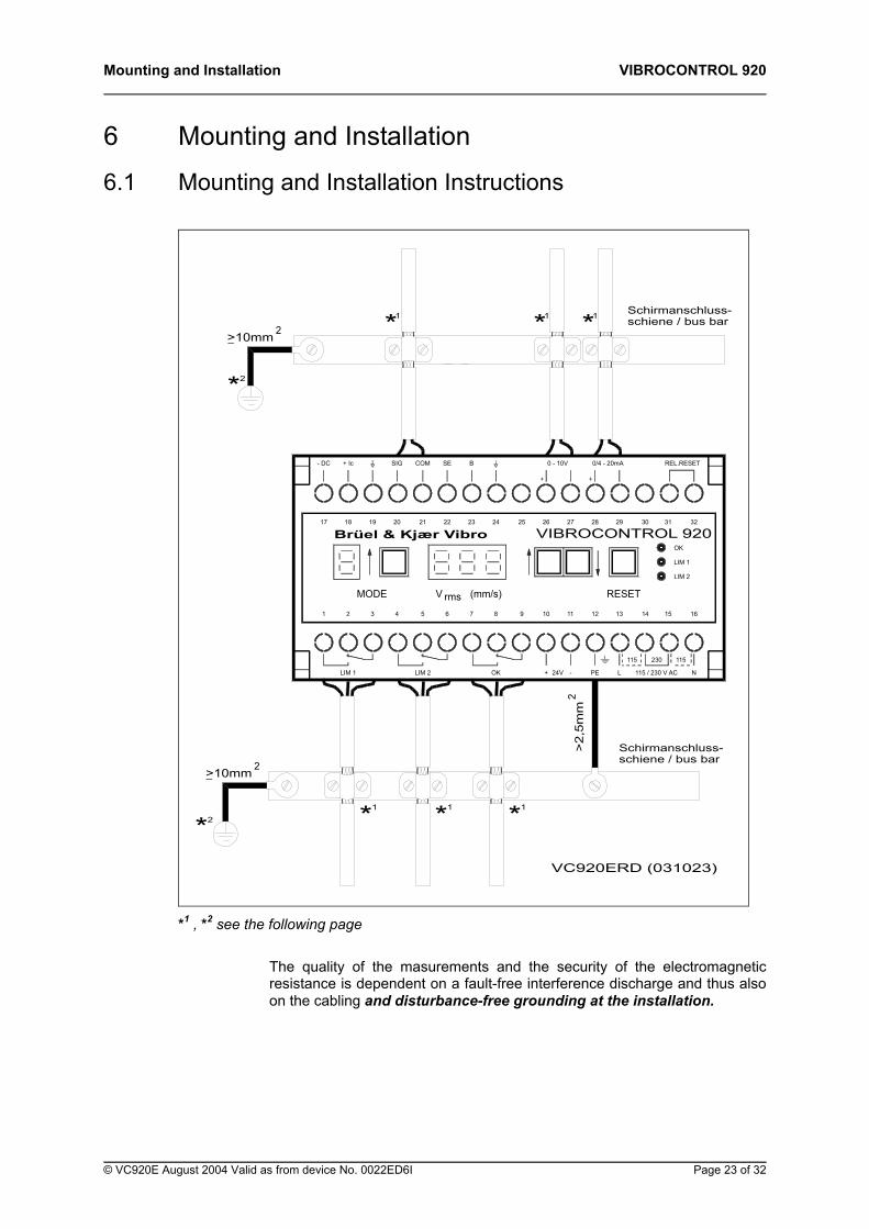
6 Mounting and Installation
6.1 Mounting and Installation Instructions
(mm/s)
7
23
B
*2
>10mm 2
* *1 1
LIM 1
1
LIM 2
2
MODE
3 4
rmsV
5 6
17
- DC
2018 19 21 22
COMSIG+ Ic SE
2>10mm
*2
*1
>2,
5mm
VC920ERD (031023)
*1
Schirmanschluss-schiene / bus bar
OK
2
+ 24V - PE
8 9 10 11 12
115 / 230 V AC
230
L
115 115
N
RESET
13 14
LIM 2
15 16
VIBROCONTROL 920
0/4 - 20mA
24 25 26 27 28
+
0 - 10V
+
29 30
LIM 1
31
OK
32
REL.RESET
**1 1 Schirmanschluss-schiene / bus bar
Brüel & Kjær Vibro
*1 , *2 see the following page
The quality of the masurements and the security of the electromagnetic resistance is dependent on a fault-free interference discharge and thus also on the cabling and disturbance-free grounding at the installation.
© VC920E August 2004 Valid as from device No. 0022ED6I Page 23 of 32
VIBROCONTROL 920 Mounting and Installation
The connecting cables for the
− sensor,
− analog outputs,
− the RESET contacts and the
− relay contacts
must be shielded.
6.2 Connecting Cable shields (*1) ♦ The connections for the cable shields must have as large an area as
possible.
♦ Use a grounding rail for connecting the shields (e.g. type 210-133 / Fa. Wago) with suitable shield clamping saddles (e.g. type 790-108 / Fa. Wago up to 8 mm cable diameter).
♦ Expose and shape the cable shield in the form of a ring at the height of the grounding rail only to the width of the grounding rail, so that the cable remains shielded right up to close to the VC-920. The cable shield must be exposed only over the grounding rail.
♦ Connect the grounding rail with short cable having a cross-sectional area of min. 10 mm2 to an interference-free ground.
6.3 Shield earth (*2) ♦ Prerequisite for a fault-free interference discharge is a low-resistance
and interference-free ground connection.
Important! Observe our „General grounding recommendations„ before cabling the system.
Page 24 of 32 © VC920E August 2004 Valid as from device No. 0022ED6I
Mounting and Installation VIBROCONTROL 920
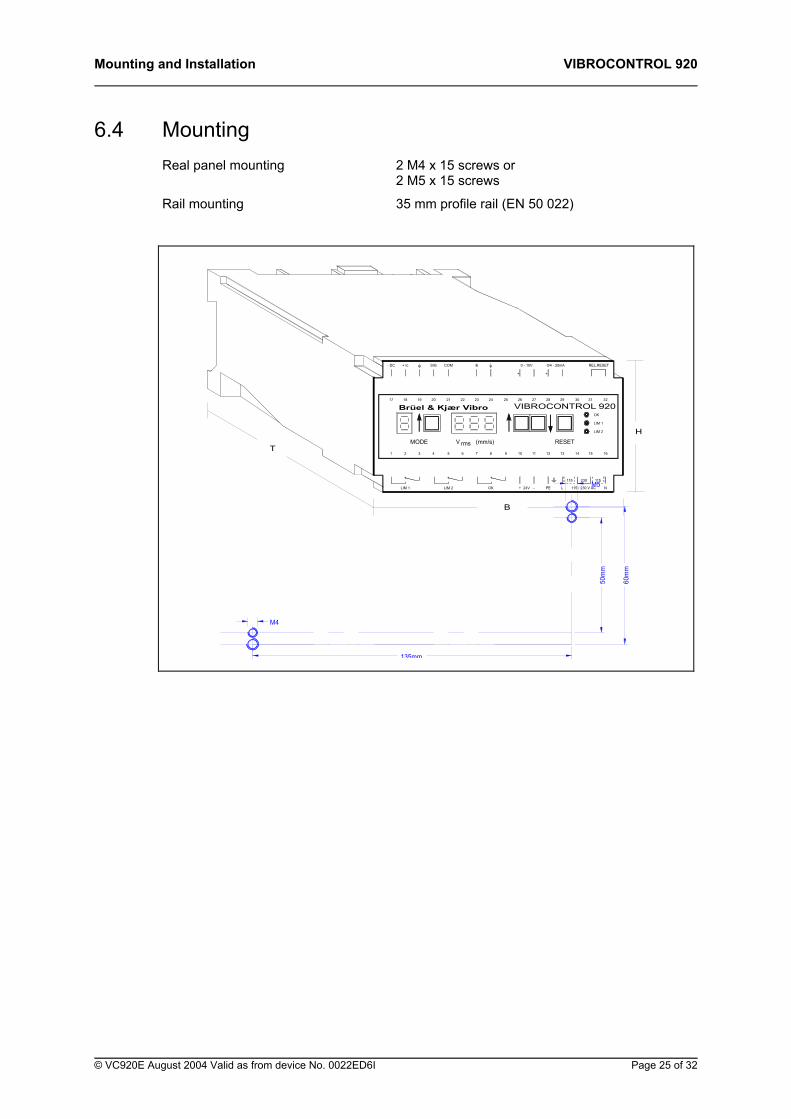
6.4 Mounting Real panel mounting 2 M4 x 15 screws or 2 M5 x 15 screws
Rail mounting 35 mm profile rail (EN 50 022)
MODE
+ Ic- DC
T321
LIM 1
18 1917
REL.RESET0/4 - 20mA0 - 10VBCOMSIG
VIBROCONTROL 920
B
+
26
10
+
9
V rms (mm/s)
87654
OKLIM 2
252423222120
161514
115
N
230
115 / 230 V AC
131211
LPE-24V
RESET
115
323130
LIM 2
LIM 1
OK
+
292827
H
Brüel & Kjær Vibro
135mm
M4
M5
60m
m
50m
m
© VC920E August 2004 Valid as from device No. 0022ED6I Page 25 of 32
VIBROCONTROL 920 Mounting and Installation
This page is for your notes.
Page 26 of 32 © VC920E August 2004 Valid as from device No. 0022ED6I
Wiring diagrams VIBROCONTROL 920
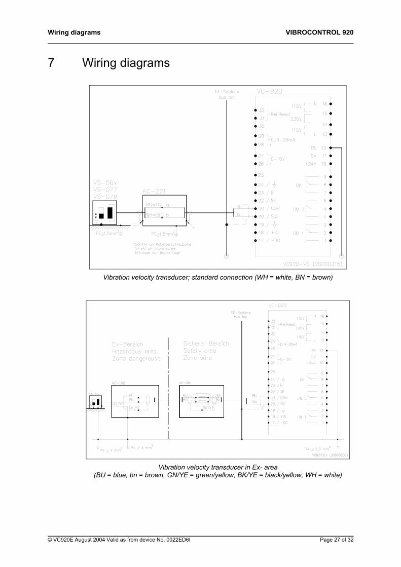
7 Wiring diagrams
Vibration velocity transducer; standard connection (WH = white, BN = brown)
Vibration velocity transducer in Ex- area
(BU = blue, bn = brown, GN/YE = green/yellow, BK/YE = black/yellow, WH = white)
© VC920E August 2004 Valid as from device No. 0022ED6I Page 27 of 32
VIBROCONTROL 920 Wiring diagrams
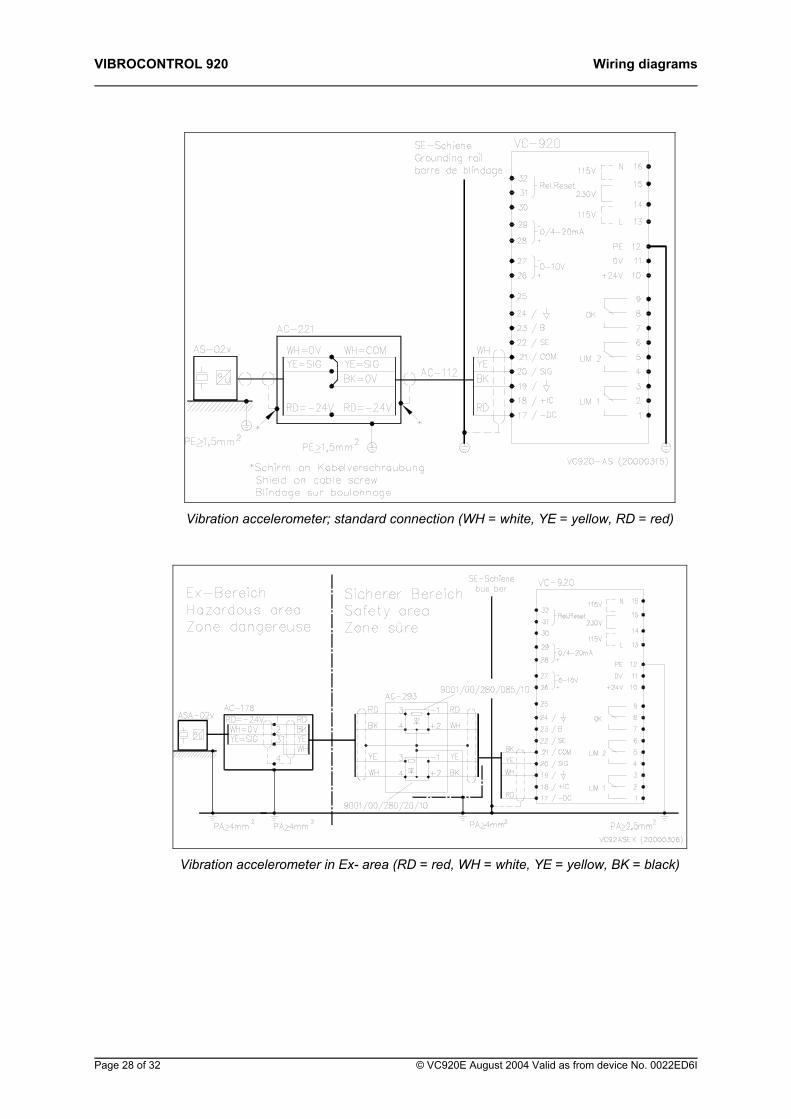
Vibration accelerometer; standard connection (WH = white, YE = yellow, RD = red)
Vibration accelerometer in Ex- area (RD = red, WH = white, YE = yellow, BK = black)
Page 28 of 32 © VC920E August 2004 Valid as from device No. 0022ED6I
Wiring diagrams VIBROCONTROL 920
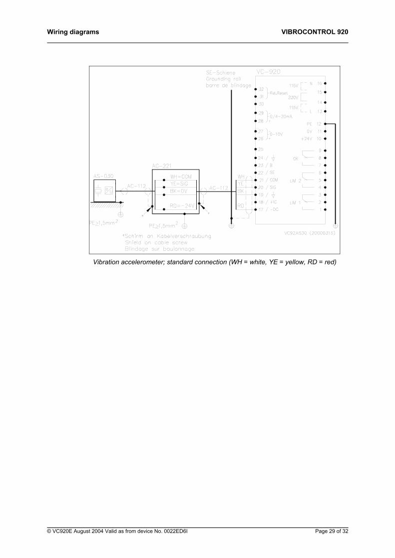
Vibration accelerometer; standard connection (WH = white, YE = yellow, RD = red)
© VC920E August 2004 Valid as from device No. 0022ED6I Page 29 of 32
VIBROCONTROL 920 Wiring diagrams
*Schirm an Kabelverschraubung Shield on cable screw Blindage sur boulonnage VC920-CCS (031023)
*
ua
*
PE>1,5mm2
0Vba
SIG/I
AC-22125
PE>1,5mm2
ab
/19 3
LIM 1-DC
+IC
17 /
18 /
1
2
LIM 2
22
COM
SIG20
21 /
/
B23 /
24 /
6
5
4
OK7
9
8
SE-Schienebus bar
30 14115V
0-10V27
26
0/4-20mA28
29
0V 11
+24V 10
PE 12
L 13
230V
115V
Rel.Reset32
31
VC-920
15
N 16
AS-062
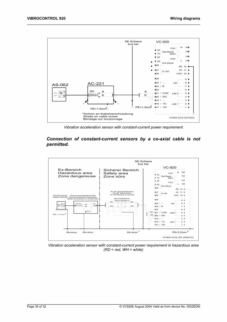
Vibration acceleration sensor with constant-current power requirement
Connection of constant-current sensors by a co-axial cable is not permitted.
Sicherer BereichSafety areaZone sûre
PA>4mmPA>4mm2 2
Ex-BereichHazardous areaZone dangereuse
0-10V
-DC
+IC
COM
SIG
B
20 /
PA>4mm 2
/
17 /
18
/19
22
/21
/23
25
24 /
26
4
PA>2,5mm
VC920-CCS_EX (040212)
LIM 1
2
1
2
3
LIM 2
OK
+24V
6
5
7
9
8
10
0/4-20mA
VC-920
Rel.Reset
29
27
28
30
32
31
SE-Schienebus bar
115VL
0V
PE
N115V
230V
13
11
12
16
14
15
9001/01/280/085/10
PA/ > 4 mm
ua
2
RD=SIG
WH=COM
BK/YE4
2
1 RD
WH
3
4
RD
WH
+1
-2
RD
WH
AC-297 SicherheitsbarriereAC-297 Safety barrier
AC-297 Barrière de sécuritéKlemmenschutzgehäuse EExiTerminal protective housing EExi
Boîtier de protection du bornier EExi
ASA-062 SensorCapteur ASA-062
9001/01/280/085/101
4RD
WH
Vibration acceleration sensor with constant-current power requirement in hazardous area
(RD = red, WH = white)
Page 30 of 32 © VC920E August 2004 Valid as from device No. 0022ED6I
Wiring diagrams VIBROCONTROL 920
This page is for your notes.
© VC920E August 2004 Valid as from device No. 0022ED6I Page 31 of 32
VIBROCONTROL 920 Service
8 Service In accordance with general valid quality assurance measures the instrument should be subjected to testing, calibration and/or adjustment at regular intervals. This can be done either by the on-site service personnel, at the Brüel Kjær Vibro Ltd manufacturing facility or at one of the authorized Brüel Kjær Vibro service stations. An inspection of this type is recommended at intervals of 5 years.
The time interval at which the calibration constants of the instrument should be subjected to automatic correction is 12 months.
Page 32 of 32 © VC920E August 2004 Valid as from device No. 0022ED6I
Instrument versions VIBROCONTROL 920
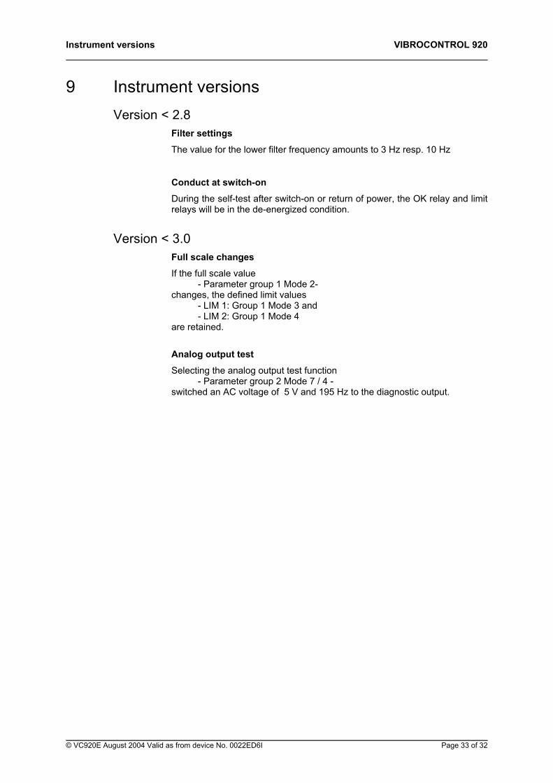
9 Instrument versions Version < 2.8
Filter settings
The value for the lower filter frequency amounts to 3 Hz resp. 10 Hz
Conduct at switch-on
During the self-test after switch-on or return of power, the OK relay and limit relays will be in the de-energized condition.
Version < 3.0 Full scale changes
If the full scale value - Parameter group 1 Mode 2- changes, the defined limit values - LIM 1: Group 1 Mode 3 and - LIM 2: Group 1 Mode 4 are retained.
Analog output test
Selecting the analog output test function - Parameter group 2 Mode 7 / 4 - switched an AC voltage of 5 V and 195 Hz to the diagnostic output.
© VC920E August 2004 Valid as from device No. 0022ED6I Page 33 of 32
VIBROCONTROL 920 Parameter list
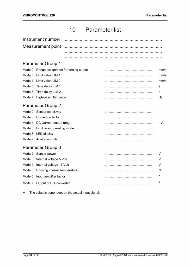
10 Parameter list Instrument number ............................................................................... Measurement point ............................................................................... ............................................................................... ............................................................................... Parameter Group 1 Mode 2 Range assignment for analog output ....................................................... mm/s
Mode 3 Limit value LIM 1 ....................................................... mm/s
Mode 4 Limit value LIM 2 ....................................................... mm/s
Mode 5 Time delay LIM 1 ....................................................... s
Mode 6 Time delay LIM 2 ....................................................... s
Mode 7 High-pass filter value ....................................................... Hz
Parameter Group 2 Mode 2 Sensor sensitivity .......................................................
Mode 3 Correction factor .......................................................
Mode 4 DC Current output range ....................................................... mA
Mode 5 Limit relay operating mode .......................................................
Mode 6 LED display .......................................................
Mode 7 Analog outputs .......................................................
Parameter Group 3 Mode 2 Sensor power ....................................................... V
Mode 3 Internal voltage 5 Volt ....................................................... V
Mode 4 Internal voltage 17 Volt ....................................................... V
Mode 5 Housing internal temperature ....................................................... °C
Mode 6 Input amplifier factor ....................................................... *
Mode 7 Output of D/A converter ....................................................... *
∗ The value is dependent on the actual input signal.
Page 34 of 32 © VC920E August 2004 Valid as from device No. 0022ED6I
Parameter list VIBROCONTROL 920
© VC920E August 2004 Valid as from device No. 0022ED6I Page 35 of 32
This page is for your notes.