Embed Size (px)
Citation preview
TECHNICKÁ DOKUMENTACE R2000
FLOW CLIMA, s. r. o.
Baarova 2, 140 00 Praha 4, Czech RepublicTel.: +420 241 483 130Fax: +420 241 483 129
Hviezdoslavova 55, 627 00 BrnoTel.: +420 548 213 005Fax: +420 548 213 016

2
Edition DOC2012, April 2007 2007 Rendamax All rights reserved. No part of this publication may be reproduced, stored in a retrieval system, or transmitted in any form or by any means, electronic, mechanical, photocopying, recording or otherwise, without the prior permission in writing of Rendamax B.V. We aim to achieve continuous improvement in our products. Therefore, specifications are subject to change without prior notice. Due to changes the product can deviate from the information specified in this document. Therefore Rendamax B.V. rejects any responsibility for the differences between the product delivered and the information mentioned in this document.
DOC2012/2000en
3 DOC2012/2000en
Index R2000 Technical data R2017-R2048 5 R2000 Technical data R2056-R2122 6 Dimensions 7 1 Introduction 8 1.1 Rendamax 8 1.2 Supplier 8 1.3 This manual 8 1.4 Service 8 1.5 General restrictions 9 2 Description 9 2.1 General information 9 2.2 Main components 10 2.3 Principle of regulation 13 2.3.1 EM Control option 13 2.3.2 EW Control option 14 2.4 Boiler protection 17 3 Safety 17 4 Delivery and transport 19 4.1 Delivery 19 4.2 Unit protective packaging 19 4.3 Transport 19 5 Installation 20 5.1 Boiler room 20 5.1.1 Siting 20 5.1.2 Boiler room ventilation 20 5.2 Unit connections 20 5.2.1 Gas supply 20 5.2.2 Electrical supply 21 5.2.3 Hydraulic connections 21 5.2.4 Flues 22 5.3 Water quality 23 5.4 Hydraulic system 24 5.4.1 Flow and resistance 24 5.4.2 Examples hydraulic system 27 6 Commissioning 30 6.1 General 30 6.2 Pre-lighting checks and dry run 33 6.2.1 Check 1 33 6.2.2 Check 2 33 6.2.3 Check 3 35 6.3 Live run check 35 6.4 Instructions to user 37
4 DOC2012/2000en
7 Operation and fault indication 37 7.1 Function 37 7.2 Regulation 37 7.3 Control panel 37 7.4 Fault indications 38 7.5 Start-up 39 7.6 Shut-down 39 7.7 Warnings 39 7.8 Fault finding table 40 8 Maintenance 42 8.1 Safety 42 8.2 General information 42 8.3 Inspection 42 8.4 Cleaning 43 8.5 Servicing 43 8.6 Component replacement 47 8.7 Service 49 Notes 50
DOC2012/2000en
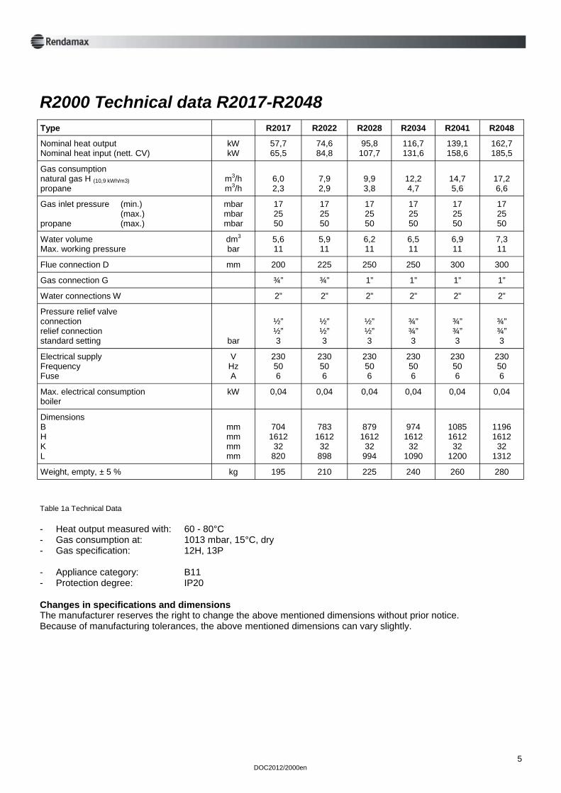
R2000 Technical data R2017-R2048
5
Type R2017 R2022 R2028 R2034 R2041 R2048
Nominal heat output Nominal heat input (nett. CV)
kW kW
57,7 65,5
74,6 84,8
95,8 107,7
116,7 131,6
139,1 158,6
162,7 185,5
Gas consumption natural gas H (10,9 kWh/m3) propane
m3/h m3/h
6,0 2,3
7,9 2,9
9,9 3,8
12,2 4,7
14,7 5,6
17,2 6,6
Gas inlet pressure (min.) (max.) propane (max.)
mbar mbar mbar
17 25 50
17 25 50
17 25 50
17 25 50
17 25 50
17 25 50
Water volume Max. working pressure
dm3
bar 5,6 11
5,9 11
6,2 11
6,5 11
6,9 11
7,3 11
Flue connection D mm 200 225 250 250 300 300
Gas connection G ¾” ¾” 1” 1” 1” 1”
Water connections W 2” 2” 2” 2” 2” 2”
Pressure relief valve connection relief connection standard setting
bar
½” ½” 3
½” ½” 3
½” ½” 3
¾” ¾” 3
¾” ¾” 3
¾” ¾” 3
Electrical supply Frequency Fuse
V Hz A
230 50 6
230 50 6
230 50 6
230 50 6
230 50 6
230 50 6
Max. electrical consumption boiler
kW 0,04 0,04 0,04 0,04 0,04 0,04
Dimensions B H K L
mm mm mm mm
704 1612 32
820
783
1612 32 898
879 1612 32
994
974 1612 32
1090
1085 1612 32
1200
1196 1612
32 1312
Weight, empty, ± 5 % kg 195 210 225 240 260 280
Table 1a Technical Data - Heat output measured with: 60 - 80°C - Gas consumption at: 1013 mbar, 15°C, dry - Gas specification: 12H, 13P - Appliance category: B11 - Protection degree: IP20 Changes in specifications and dimensions The manufacturer reserves the right to change the above mentioned dimensions without prior notice. Because of manufacturing tolerances, the above mentioned dimensions can vary slightly.
6 DOC2012/2000en
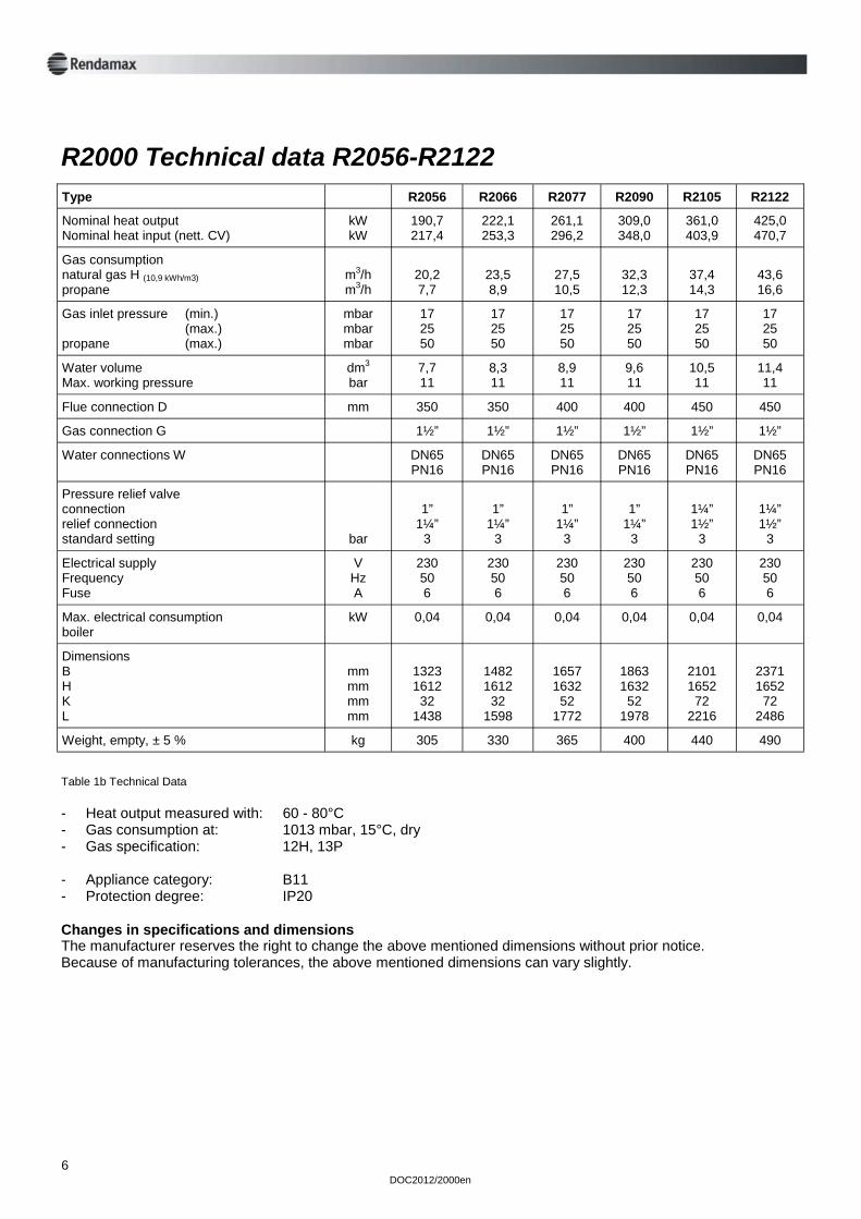
R2000 Technical data R2056-R2122
Table 1b Technical Data - Heat output measured with: 60 - 80°C - Gas consumption at: 1013 mbar, 15°C, dry - Gas specification: 12H, 13P - Appliance category: B11 - Protection degree: IP20 Changes in specifications and dimensions The manufacturer reserves the right to change the above mentioned dimensions without prior notice. Because of manufacturing tolerances, the above mentioned dimensions can vary slightly.
Type R2056 R2066 R2077 R2090 R2105 R2122
Nominal heat output Nominal heat input (nett. CV)
kW kW
190,7 217,4
222,1 253,3
261,1 296,2
309,0 348,0
361,0 403,9
425,0 470,7
Gas consumption natural gas H (10,9 kWh/m3) propane
m3/h m3/h
20,2 7,7
23,5 8,9
27,5 10,5
32,3 12,3
37,4 14,3
43,6 16,6
Gas inlet pressure (min.) (max.) propane (max.)
mbar mbar mbar
17 25 50
17 25 50
17 25 50
17 25 50
17 25 50
17 25 50
Water volume Max. working pressure
dm3
bar 7,7 11
8,3 11
8,9 11
9,6 11
10,5 11
11,4 11
Flue connection D mm 350 350 400 400 450 450
Gas connection G 1½” 1½” 1½” 1½” 1½” 1½”
Water connections W DN65 PN16
DN65 PN16
DN65 PN16
DN65 PN16
DN65 PN16
DN65 PN16
Pressure relief valve connection relief connection standard setting
bar
1”
1¼” 3
1”
1¼” 3
1”
1¼” 3
1”
1¼” 3
1¼” 1½”
3
1¼” 1½”
3
Electrical supply Frequency Fuse
V Hz A
230 50 6
230 50 6
230 50 6
230 50 6
230 50 6
230 50 6
Max. electrical consumption boiler
kW 0,04 0,04 0,04 0,04 0,04 0,04
Dimensions B H K L
mm mm mm mm
1323 1612 32
1438
1482 1612 32
1598
1657 1632 52
1772
1863 1632 52
1978
2101 1652 72
2216
2371 1652
72 2486
Weight, empty, ± 5 % kg 305 330 365 400 440 490
DOC2012/2000en
7
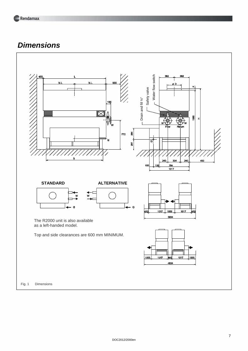
Dimensions
Dra
in a
nd fi
ll ½
“
Saf
ety
valv
e
Wat
er fl
ow s
witc
h
STANDARD ALTERNATIVE
Fig. 1 Dimensions
The R2000 unit is also available as a left-handed model. Top and side clearances are 600 mm MINIMUM.
8 DOC2012/2000en
1 Introduction 1.1 Rendamax
Since its beginning in 1968, Rendamax has built up a strong reputation in industry for the development, production and marketing of gas-fired, high efficiency boilers in the 60 to 1200 kW range. Through their unique construction, these central heating units are renowned for their: - high thermal efficiency - environmental friendliness - light weight and small dimensions - durability - low noise production - large regulating range - available with many different options Continual research and development means that Rendamax remains at the forefront of boiler and water heater technology.
1.2 Supplier Rendamax boilers are sold by your supplier (see cover). For advice or more information with regard to our products contact your supplier. 1.3 This manual This documentation has been produced to aid the following target groups: - the consulting engineer - the heating installer - the service engineer - the user Because these target groups require mostly similar information and also specific information, our technical documentation has been integrated to provide these target groups with the necessary general and specific information to install, service and operate this product. The supplier (see cover) will be able to provide any further or supplemental information. The following aspects will be explained: - general description - technical specifications - necessary services for system design and unit installation - example systems - maintenance instructions Operating instructions for the user can be found on the unit. See also chapter 7. 1.4 Service For commissioning and assistance in maintenance matters, please contact your supplier’s service department. For more details see section cover.
DOC2012/2000en
9
1.5 Reservation It is the law that the installation be carried out by a competent person. The boiler should be in-stalled in accordance with the British Standards and Codes of Practice referred to in this manual, the Gas Safety (installation & use) Regulations 1994, Building Regulations, Model Water Bye-laws and any Require ments of the Local Gas Supplier, Local Authority, Water and Fire Authorities and I.E.E. Regulations. Health & Safety at Work Act, 1974 Under Section 6 of the above Act, it is the duty of manufactur ers and suppliers of products for use at work to ensure, so far as it is reasonable practicable, that such products are safe and without risk to health when properly used and to make available to users of such products adequate information about their safe and proper operation. Rendamax boilers should only be used in the manner and purpose for wich they were intended, and in accordance with the recommendations detailed in this manual. Our heaters have been designed, produced and inspected with safety in mind, but there are certain basic precautions, wich should be taken by the user and, in particular attention is drawn to the safety precautions in this manual and to the operating instructions on the heater. It is imperative, therefore, that all persons who make use of our heaters have all the information and instructions they require to ensure that they are fully aware of any hazard, and that they know both the purpose and correct manner of use of our heaters. The manufacturer can alter its products without any preceding notification and is therefore not obliged to adapt earlier delivered products.
2 Description 2.1 General information The R2000 series boilers are atmospheric open flued, low thermal capacity gas-fi red boilers. These high efficiency boilers are designed to provide heating and hot water services for a wide variety of industrial and com mercial premises. The R2000 series of boilers are available in 12 types: R2017, R2022, R2028, R2034, R2041, R2048, R2056, R2066, R2077, R2090, R2105, R2122. The last three digits of the type number indicate the number of burner bars present in the burner assembly. The load at nett calorific value is approx. 3,5 kW per burner. All boiler types are fitted with a 9-tube heat exchanger of the 2 pass type. The use of extruded copper fin pipes in the heat exchanger leads to higher effi ciency. Thermal radiation losses are minimized by the optimal construction of the combustion chamber in which high-grade insu lation is integrated. The advanced construction of the R2000 enables swift assem bly and dismantle, which simplifi es maintenance and inspection. All boilers have full sequence automatic control with overheat cut off, water flow switch, modulating turn down on gas and combustion air (for improved efficiency at varying heat loads) and fault indicators. The R2000 has an electronic protection and ignition system, indicated by E. The electronic PID version controlled by a simple to operate regulator is indicated in the M version. The weather compensation version with night reduction is indicated in the W version. Appliance category B11.
The R2000 series is CE approved for the following countries: Great Britain, Belgium, Denmark, France, Ireland, Italy, Spain and Sweden under Product Identification Number 0063AQ6600.
10 DOC2012/2000en
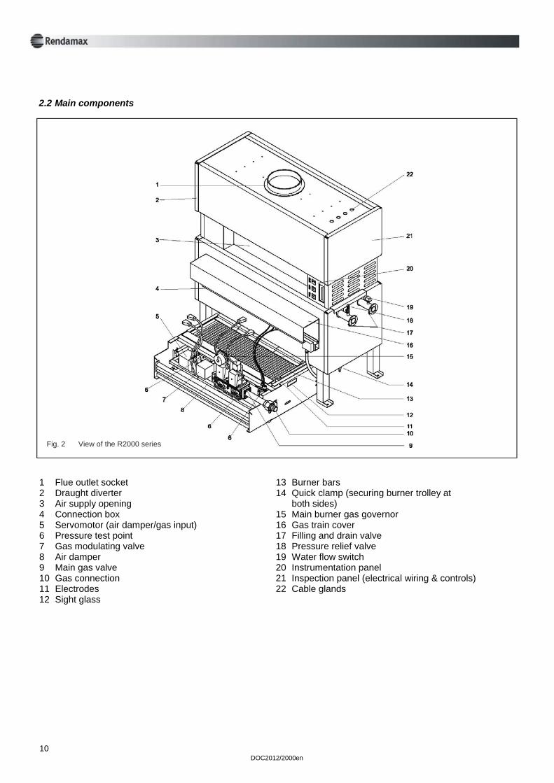
1 Flue outlet socket 2 Draught diverter 3 Air supply opening 4 Connection box 5 Servomotor (air damper/gas input) 6 Pressure test point 7 Gas modulating valve 8 Air damper 9 Main gas valve 10 Gas connection 11 Electrodes 12 Sight glass
13 Burner bars 14 Quick clamp (securing burner trolley at both sides) 15 Main burner gas governor 16 Gas train cover 17 Filling and drain valve 18 Pressure relief valve 19 Water flow switch 20 Instrumentation panel 21 Inspection panel (electrical wiring & controls) 22 Cable glands
2.2 Main components
Fig. 2 View of the R2000 series
DOC2012/2000en
11
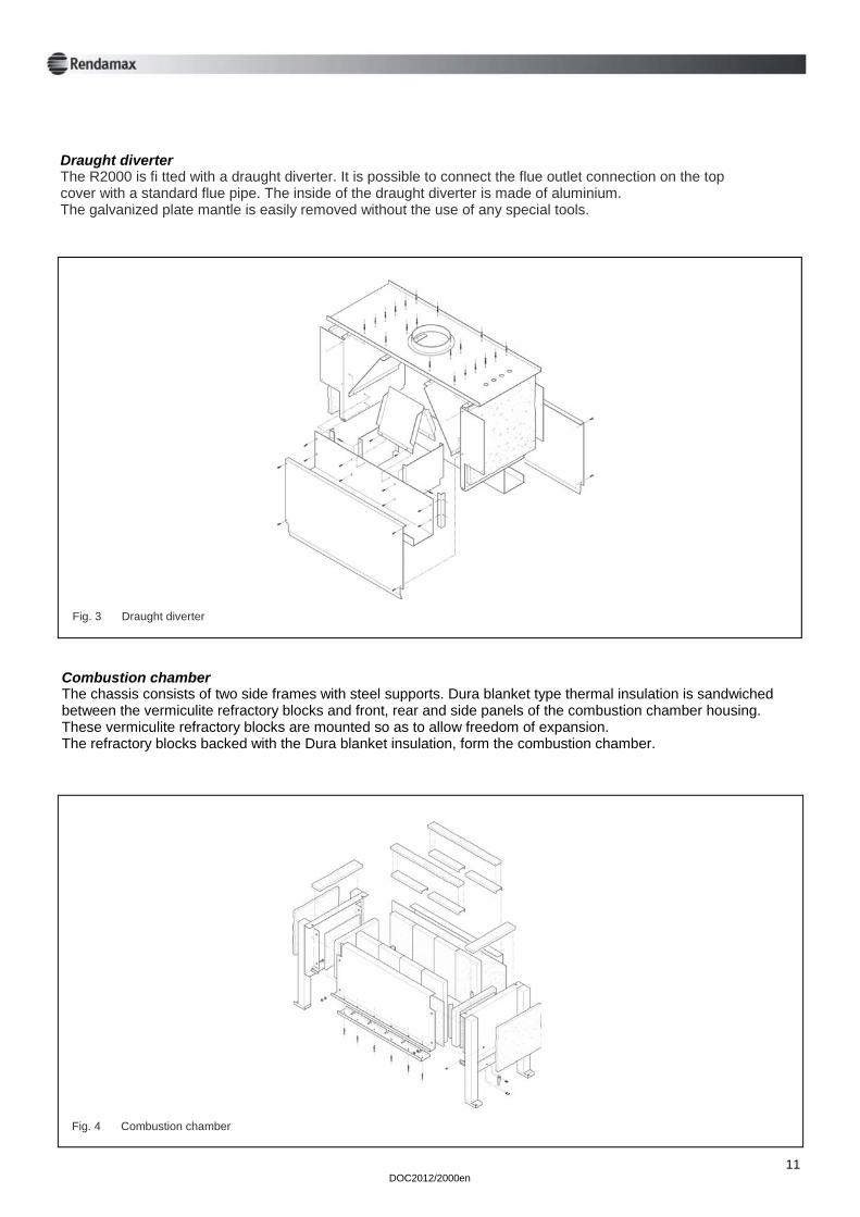
Draught diverter The R2000 is fi tted with a draught diverter. It is possible to connect the flue outlet connection on the top cover with a standard flue pipe. The inside of the draught diverter is made of aluminium. The galvanized plate mantle is easily removed without the use of any special tools.
Fig. 3 Draught diverter
Combustion chamber The chassis consists of two side frames with steel supports. Dura blanket type thermal insulation is sandwiched between the vermiculite refractory blocks and front, rear and side panels of the combustion chamber housing. These vermiculite refractory blocks are mounted so as to allow freedom of expansion. The refractory blocks backed with the Dura blanket insulation, form the combustion chamber.
Fig. 4 Combustion chamber
12 DOC2012/2000en
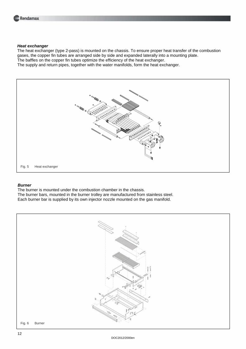
Heat exchanger The heat exchanger (type 2-pass) is mounted on the chassis. To ensure proper heat transfer of the combustion gases, the copper fin tubes are arranged side by side and expanded laterally into a mounting plate. The baffles on the copper fin tubes optimize the efficiency of the heat exchanger. The supply and return pipes, together with the water manifolds, form the heat exchanger.
Burner The burner is mounted under the combustion chamber in the chassis. The burner bars, mounted in the burner trolley are manufactured from stainless steel. Each burner bar is supplied by its own injector nozzle mounted on the gas manifold.
Fig. 6 Burner
Fig. 5 Heat exchanger
DOC2012/2000en
13
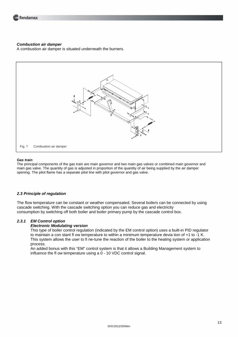
Combustion air damper A combustion air damper is situated underneath the burners.
Fig. 7 Combustion air damper
Gas train The principal components of the gas train are main governor and two main gas valves or combined main governor and main gas valve. The quantity of gas is adjusted in proportion of the quantity of air being supplied by the air damper opening. The pilot flame has a separate pilot line with pilot governor and gas valve.
2.3 Principle of regulation The flow temperature can be constant or weather compensated. Several boilers can be connected by using cascade switching. With the cascade switching option you can reduce gas and electricity consumption by switching off both boiler and boiler primary pump by the cascade control box. 2.3.1 EM Control option Electronic Modulating version This type of boiler control regulation (indicated by the EM control option) uses a built-in PID regulator to maintain a con stant fl ow temperature to within a minimum temperature devia tion of +1 to -1 K. This system allows the user to fi ne-tune the reaction of the boiler to the heating system or application process. An added bonus with this “EM” control system is that it allows a Building Management system to influence the fl ow temperature using a 0 - 10 VDC control signal.
14 DOC2012/2000en
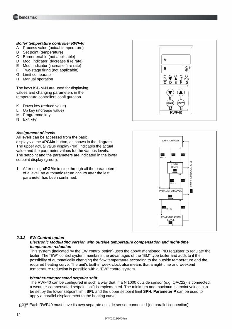
Boiler temperature controller RWF40 A Process value (actual temperature) B Set point (temperature) C Burner enable (not applicable) D Mod. indicator (decrease fi re rate) E Mod. indicator (increase fi re rate) F Two-stage firing (not applicable) G Limit comparator H Manual operation The keys K-L-M-N are used for displaying values and changing parameters in the temperature controllers confi guration. K Down key (reduce value) L Up key (increase value) M Programme key N Exit key Assignment of levels All levels can be accessed from the basic display via the «PGM» button, as shown in the diagram. The upper actual value display (red) indicates the actual value and the parameter values for the various levels. The setpoint and the parameters are indicated in the lower setpoint display (green). 1. After using «PGM» to step through all the parameters of a level, an automatic return occurs after the last parameter has been confirmed.
2.3.2 EW Control option Electronic Modulating version with outside temperature compensation and night-time temperature reduction This system (indicated by the EW control option) uses the above mentioned PID regulator to regulate the boiler. The “EW” control system maintains the advantages of the “EM” type boiler and adds to it the possibility of automatically changing the flow temperature according to the outside temperature and the required heating curve. The unit’s built-in week-clock also means that a night-time and weekend temperature reduction is possible with a “EW” control system. Weather-compensated setpoint shift The RWF40 can be configured in such a way that, if a Ni1000 outside sensor (e.g. QAC22) is connected, a weather-compensated setpoint shift is implemented. The minimum and maximum setpoint values can be set by the lower setpoint limit SPL and the upper setpoint limit SPH. Parameter P can be used to apply a parallel displacement to the heating curve.
Each RWF40 must have its own separate outside sensor connected (no parallel connection)!
BASIC DISPLAY
USER LEVEL
PARAMETER LEVEL
CONFIGURATION LEVEL
or ti
me-
out (
appr
ox. 3
0 s)
DOC2012/2000en
15
HYS1 is the switch-on point for the burner, and HYS3 is the switch-off point. As already described, they act with the set shift relative to the weather-controlled setpoint.
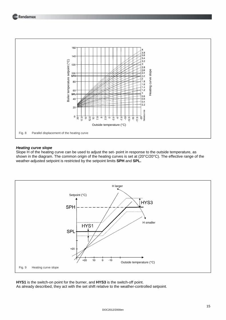
Fig. 8 Parallel displacement of the heating curve
Heating curve slope Slope H of the heating curve can be used to adjust the set- point in response to the outside temperature, as shown in the diagram. The common origin of the heating curves is set at (20°C/20°C). The effective range of the weather-adjusted setpoint is restricted by the setpoint limits SPH and SPL.
Fig. 9 Heating curve slope
B
oile
r tem
pera
ture
set
poin
t (°C
)
Outside temperature (°C)
Hea
ting
curv
e sl
ope
Setpoint (°C)
H larger
H smaller
Outside temperature (°C)
16 DOC2012/2000en
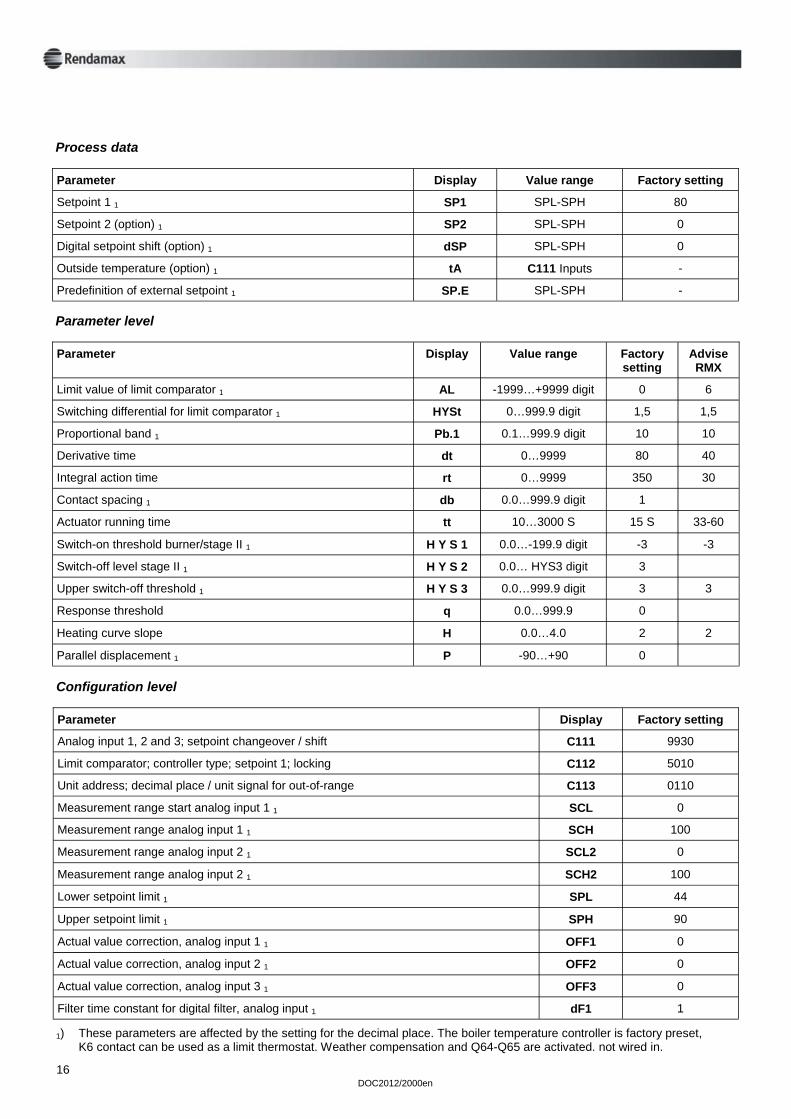
Process data
Parameter Display Value range Factory setting
Setpoint 1 1 SP1 SPL-SPH 80
Setpoint 2 (option) 1 SP2 SPL-SPH 0
Digital setpoint shift (option) 1 dSP SPL-SPH 0
Outside temperature (option) 1 tA C111 Inputs -
Predefinition of external setpoint 1 SP.E SPL-SPH -
Parameter level
Parameter Display Value range Advise RMX
Limit value of limit comparator 1 AL -1999…+9999 digit 6
Switching differential for limit comparator 1 HYSt 0…999.9 digit 1,5
Proportional band 1 Pb.1 0.1…999.9 digit 10
Derivative time dt 0…9999 40
Integral action time rt 0…9999 30
Contact spacing 1 db 0.0…999.9 digit
Actuator running time tt 10…3000 S 33-60
Switch-on threshold burner/stage II 1 H Y S 1 0.0…-199.9 digit -3
Switch-off level stage II 1 H Y S 2 0.0… HYS3 digit
Upper switch-off threshold 1 H Y S 3 0.0…999.9 digit 3
Response threshold q 0.0…999.9
Heating curve slope H 0.0…4.0 2
Parallel displacement 1 P -90…+90
Factory setting
0
1,5
10
80
350
1
15 S
-3
3
3
0
2
0
Configuration level
Parameter Display Factory setting
Analog input 1, 2 and 3; setpoint changeover / shift C111 9930
Limit comparator; controller type; setpoint 1; locking C112 5010
Unit address; decimal place / unit signal for out-of-range C113 0110
Measurement range start analog input 1 1 SCL 0
Measurement range analog input 1 1 SCH 100
Measurement range analog input 2 1 SCL2 0
Measurement range analog input 2 1 SCH2 100
Lower setpoint limit 1 SPL 44
Upper setpoint limit 1 SPH 90
Actual value correction, analog input 1 1 OFF1 0
Actual value correction, analog input 2 1 OFF2 0
Actual value correction, analog input 3 1 OFF3 0
Filter time constant for digital filter, analog input 1 dF1 1
1) These parameters are affected by the setting for the decimal place. The boiler temperature controller is factory preset, K6 contact can be used as a limit thermostat. Weather compensation and Q64-Q65 are activated. not wired in.
DOC2012/2000en
17
2.4 Boiler protection The R2000 is protected by the following systems: Water flow switch The water flow switch is installed in the flow manifold and monitors continuously the water flow. If the water flow falls below a preset level, the burner is shut down and go to lock-out. The water flow switch is factory set and should not be adjusted. High limit thermostat In the event of failure of the control thermostat, a preset high limit thermostat will shut down the burner and go to lock-out. Pressure relief valve The maximum operating pressure of the R2000 boiler is 11 bar. The standard safety valve supplied is set to 3 bar. If a different pressure setting is required this should be specified and will be set at the factory. Gas burner control The burner control unit provide control and supervision of the atmospheric burner. The sequence controller is coupled to the spindle of the control circuit and to the flame supervision unit displaying the status, the symbol appearing above the reading mark indicates the firing sequence or lock-out condition. The pilot flame is supervised by ionisation current detection.
3 Safety Installation requirements Please read these requirements before commencing installation. The product has to be installed by a recognized installer fully according to the current national and local demands, norms and standards. The installation procedure should only be used for heating systems with a maximum water temperature of 95°C. We emphasize that you should always give priority to the above mentioned standards and regulations and that the installation regulations should be considered as an addition to these standards and regulations. Explanation of the icons used in this manual
Instruction of extreme importance in order to guarantee proper functioning of the boiler.
E Not following the operation procedures can cause serious damage to the boiler, personal injuries or environmental pollution.
Electric shock hazard. Useful information.
18 DOC2012/2000en
Maintenance Work on the electrical installation should only be carried out by approved technicians and in accordance with the electro technic regulations. Work on the gas and hydraulic systems should only be carried out by approved technicians and in accordance with the safety regulations for gas installations. Keep unauthorized people away from the installation. Do not place any objects on the boiler. Keep away from the hot water connections in order to prevent burns. Always disconnect the boiler from the electric mains and close the gas service cock in the gas supply pipe before commencing maintenance and servicing operations. Check the system for leaks afterwards. In addition to the information in this documentation, always follow the standard safety regula- tions to prevent accidents. Cover panels should only be removed for maintenance and servicing tasks. Replace all panels after completing these maintenance and servicing tasks. Safety precautions The installation should never be switched on with panels removed or when boiler protection devices are not operational. Instruction and warning stickers Never remove or cover any of the instruction and warning stickers. They should always be legible throughout the life span of the boiler. Immediately replace any damaged or illegible stickers. Modification Modification of the installation should only be carried out after obtaining prior written permission from the manufacturer. Danger of explosion Follow the health and safety regulations for working in hazardous areas when working in the boiler room. Installation The boiler should be installed by a recognized installer in accordance with current regulations and the regulations of the local electric companies. Make sure that you follow all safety instructions properly. Operation In case of gas leakage, switch off the boiler and close the gas service cock. Open doors and windows, and notify the proper authorities. Follow the instructions in the manual when you use the boiler again. Technical specifications Do not exceed the specifications as layed down in the installation and maintenance instructions.
E
E
DOC2012/2000en
19
4 Delivery and transport 4.1 Delivery Before delivery, the R2000 boiler is fully assembled and tested in the factory. The R2000 is mounted on a pallet and covered in a “heat-shrink” protective wrapper. Check for damage after removing the boiler’s protective covering. Check whether the boiler conforms to the order requirements. Check whether the circuit diagram and gas-train diagram number is in accordance with the offer, order confirmation and the data on the boiler’s data number plate. 4.2 Unit protective packaging The boiler is mounted on a wooden pallet. For transportation the boiler is covered in a “heatshrink” protective covering. The panel-work is also covered in a protective polyethylene layer. Before final installation in the boiler room the boiler must be removed from the pallet and all protective coverings removed. The protective coverings should be disposed of in a environmentally friendly way. Contact your local authority. 4.3 Transport
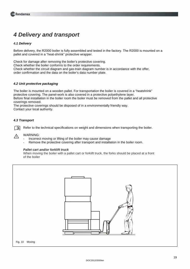
Refer to the technical specifications on weight and dimensions when transporting the boiler. WARNING: - Incorrect moving or lifting of the boiler may cause damage - Remove the protective covering after transport and installation in the boiler room. Pallet cart and/or forklift truck When moving the boiler with a pallet cart or forklift truck, the forks should be placed at a front of the boiler
E
Fig. 10 Moving
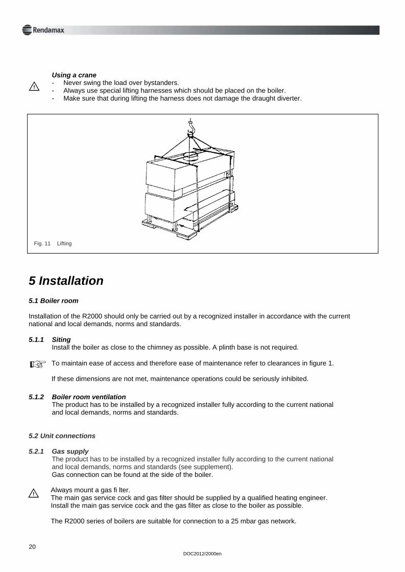
Using a crane - Never swing the load over bystanders. - Always use special lifting harnesses which should be placed on the boiler. - Make sure that during lifting the harness does not damage the draught diverter.
E
5 Installation 5.1 Boiler room Installation of the R2000 should only be carried out by a recognized installer in accordance with the current national and local demands, norms and standards. 5.1.1 Siting Install the boiler as close to the chimney as possible. A plinth base is not required.
To maintain ease of access and therefore ease of maintenance refer to clearances in figure 1. If these dimensions are not met, maintenance operations could be seriously inhibited.
5.1.2 Boiler room ventilation The product has to be installed by a recognized installer fully according to the current national and local demands, norms and standards. 5.2 Unit connections 5.2.1 Gas supply The product has to be installed by a recognized installer fully according to the current national and local demands, norms and standards (see supplement). Gas connection can be found at the side of the boiler.
Always mount a gas fi lter. The main gas service cock and gas filter should be supplied by a qualified heating engineer. Install the main gas service cock and the gas filter as close to the boiler as possible. The R2000 series of boilers are suitable for connection to a 25 mbar gas network.
E
Fig. 11 Lifting
DOC2012/2000en 20
DOC2012/2000en
The minimum supply pressure must never fall below 18 mbar. With a lower gas pressure it is possible that the boiler will not run at 100% capacity. At the same time the boiler can be more prone to failures. Adjust the burner pressure with a supply pressure of 20 mbar before the boiler.
5.2.2 Electrical supply The product has to be installed by a recognized installer fully according to the current national and local demands, norms and standards. The boiler is wired according to the circuit diagram which is supplied with the boiler. The boiler must be protected by a 6 amp fuse.
The boiler must have electrical supply voltage of 230 VAC. Do not cross connect ‘live’ and “neutral”! “Live” is connected to the terminal marked with “L” (brown), and “neutral” is connected to the ter- minal marked with “N” (blue). “Earth” is connected to the terminal “W” (yellow/green).
E
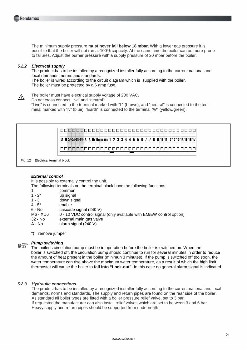
External control It is possible to externally control the unit. The following terminals on the terminal block have the following functions: 1 common 1 - 2* up signal 1 - 3 down signal 4 - 5* enable 6 - No cascade signal (240 V) M6 - XU6 0 - 10 VDC control signal (only available with EM/EW control option) 32 - No external main gas valve A - No alarm signal (240 V) *) remove jumper Pump switching The boiler’s circulation pump must be in operation before the boiler is switched on. When the boiler is switched off, the circulation pump should continue to run for several minutes in order to reduce the amount of heat present in the boiler (minimun 3 minutes). If the pump is switched off too soon, the water temperature can rise above the maximum water temperature, as a result of which the high limit thermostat will cause the boiler to fall into “Lock-out”. In this case no general alarm signal is indicated.
21
5.2.3 Hydraulic connections The product has to be installed by a recognized installer fully according to the current national and local demands, norms and standards. The supply and return pipes are found on the rear side of the boiler. As standard all boiler types are fitted with a boiler pressure relief valve, set to 3 bar. If requested the manufacturer can also install relief valves which are set to between 3 and 6 bar. Heavy supply and return pipes should be supported from underneath.
Fig. 12 Electrical terminal block
22 DOC2012/2000en
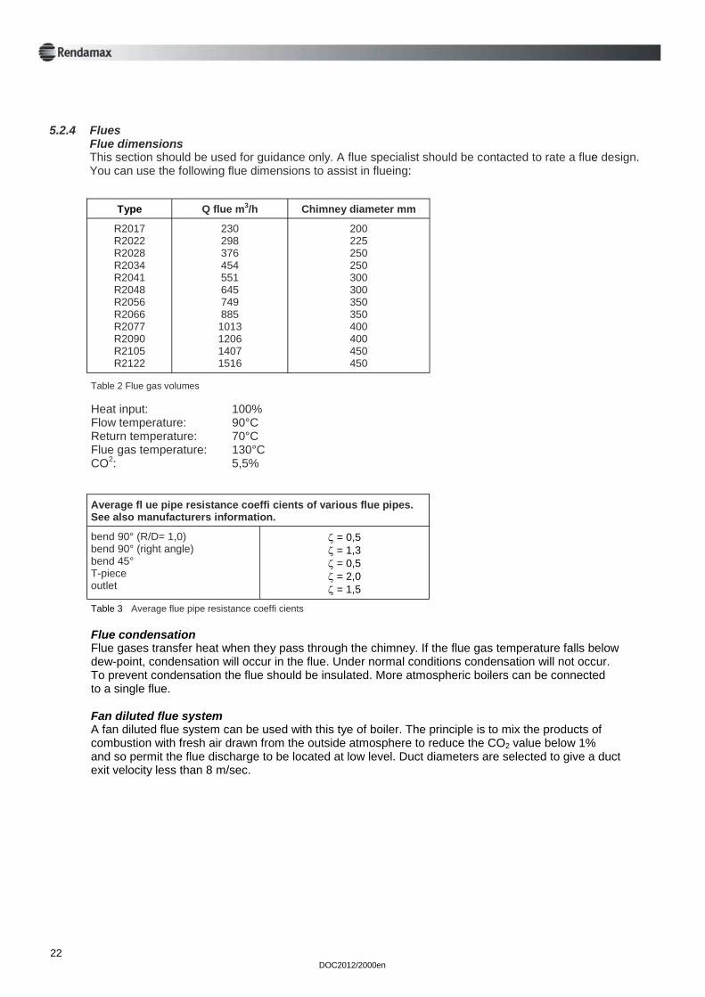
5.2.4 Flues Flue dimensions This section should be used for guidance only. A flue specialist should be contacted to rate a flue design. You can use the following flue dimensions to assist in flueing:
Type Q flue m3/h Chimney diameter mm
R2017 R2022 R2028 R2034 R2041 R2048 R2056 R2066 R2077 R2090 R2105 R2122
230 298 376 454 551 645 749 885 1013 1206 1407 1516
200 225 250 250 300 300 350 350 400 400 450 450
Table 2 Flue gas volumes Heat input: 100% Flow temperature: 90°C Return temperature: 70°C Flue gas temperature: 130°C CO2: 5,5%
Average fl ue pipe resistance coeffi cients of various flue pipes. See also manufacturers information.
bend 90° (R/D= 1,0) bend 90° (right angle) bend 45° T-piece outlet
ζ = 0,5 ζ = 1,3 ζ = 0,5 ζ = 2,0 ζ = 1,5
Table 3 Average flue pipe resistance coeffi cients Flue condensation Flue gases transfer heat when they pass through the chimney. If the flue gas temperature falls below dew-point, condensation will occur in the flue. Under normal conditions condensation will not occur. To prevent condensation the flue should be insulated. More atmospheric boilers can be connected to a single flue. Fan diluted flue system A fan diluted flue system can be used with this tye of boiler. The principle is to mix the products of combustion with fresh air drawn from the outside atmosphere to reduce the CO2 value below 1% and so permit the flue discharge to be located at low level. Duct diameters are selected to give a duct exit velocity less than 8 m/sec.
DOC2012/2000en
23
5.3 Water quality
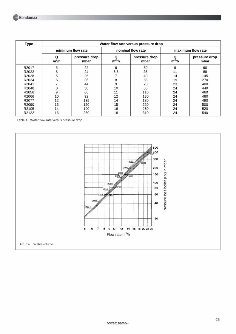
Corrosive elements in certain additives can attack the system, resulting in leakage; deposits of undesirable sediments can lead to damage to the boiler heat exchanger. For water hardness, a distinction must be made between: a Temporary hardness This is also referred to as carbonate hardness. Deposits are formed at higher temperatures and are easy to remove. b Permanent hardness Minerals (for example, calcium sulphate) dissolved in the water can be deposited as a function of very high surface temperatures. In the United Kingdom, water hardness is expressed in mg/litre (ppm) and is given the following divisions: Very soft less than 50 ppm Soft approx. 50 - 160 ppm Moderately hard approx. 160 - 250 ppm Hard and very hard over 250 ppm. The system must contain soft to moderately hard water with a water hardness not exceeding 250 ppm with a supply temperature of 80°C and ∆T = 20 K. During the construction of larger installations, one of the appliances may be operational. New circuits may be regularly switched in, which must occur together with the addition of fresh water. In addition, it can happen that, because of leakage, some circuits must be disconnected, repaired and re-filled. In these circumstances the only appliance in operation often functions at full capacity and the chance of boiler scale formation is present. For this reason the make-up water must be softened. To ensure proper functioning of the appliance and the system, the use of water softeners is recommended. Large stationary air bubbles with widely different compositions can form at “dead points" in the system (in addition to oxygen and nitrogen, hydrogen and methane have also been detected). Oxygen promotes corrosion. Corrosion products, together with other pollutants, form a sludge deposit (magnetite) which causes pitting under the influence of oxygen. The use of an air separator with an automatic de-aerator is strongly recommended. This should preferably be fitted in a horizontal section of the return pipe to the pump. If a vertical distributor is employed, the air separator should be fitted above the distributor. To reduce the effects of unnecessary wear and blockages resulting from any pollution present we advise the use of a filter system with a mesh opening of 100 microns. Always fit this in the return pipe of the secondary part of the system. In order to guarantee a well functioning system and a long life, any suspended and corrosion producing particles must be removed with the aid of a well chosen and fitted filter system. The analysis of system water and the cleaning of filters must form part of the periodic inspection procedure. If there is an intention to add chemicals (such as inhibitors) to the water, contact must be made with your supplier. They can provide advice on filter systems and other requirements. (Water analysis forms can be obtained from your supplier). As the heat exchanger only has a small volume, minimum water flow is absolutely necessary. This water flow is secured by the water flow switch. There is a relationship between the maximum water flow temperature, the system pressure and the water volume which flows through the boiler per unit time at a specified boiler load. In case of high water flow temperature, low water velocity in the heat exchanger and low pressure, steam forming may occur. Figure 14 shows the relationship between water volume and differential pressure over the heat exchanger.
E
24 DOC2012/2000en
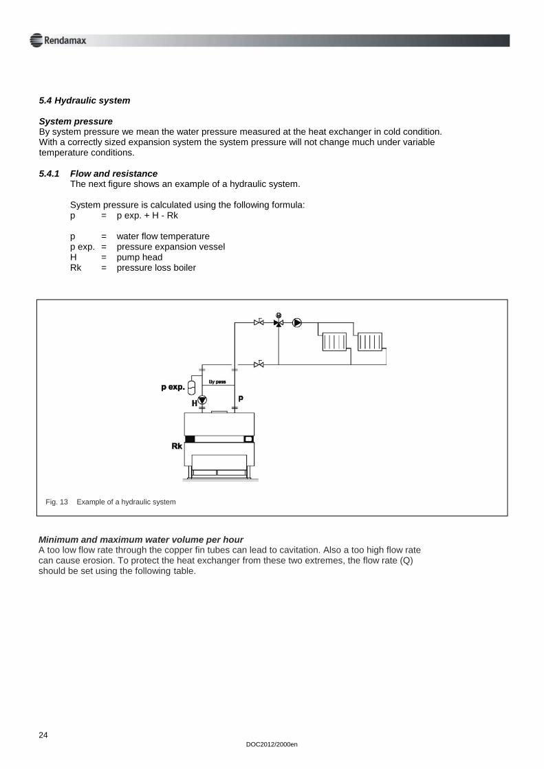
5.4 Hydraulic system System pressure By system pressure we mean the water pressure measured at the heat exchanger in cold condition. With a correctly sized expansion system the system pressure will not change much under variable temperature conditions. 5.4.1 Flow and resistance The next figure shows an example of a hydraulic system. System pressure is calculated using the following formula: p = p exp. + H - Rk p = water flow temperature p exp. = pressure expansion vessel H = pump head Rk = pressure loss boiler
Fig. 13 Example of a hydraulic system
Minimum and maximum water volume per hour A too low flow rate through the copper fin tubes can lead to cavitation. Also a too high flow rate can cause erosion. To protect the heat exchanger from these two extremes, the flow rate (Q) should be set using the following table.
DOC2012/2000en
25
Type Water flow rate versus pressure drop
minimum flow rate nominal flow rate
Q m3/h
pressure drop mbar
Q m3/h
pressure drop mbar
Q m3/h
pressure drop mbar
R2017 R2022 R2028 R2034 R2041 R2048 R2056 R2066 R2077 R2090 R2105 R2122
5 5 5 6 7 8 9
10 12 13 14 16
22 24 26 36 44 58 66 92
135 150 190 260
6 6,5 7 8 9 10 11 12 14 15 16 18
30 35 40 55 70 85 110 130 180 220 250 310
9 11 14 19 23 24 24 24 24 24 24 24
60 88
145 270 400 440 460 480 490 500 520 540
maximum flow rate
Table 4 Water flow rate versus pressure drop
Fig. 14 Water volume
Pre
ssur
e lo
ss b
oile
r (R
k) in
mba
r
Flow rate m3/h
26 DOC2012/2000en
Positioning the pump and expansion vessel We advise that the pump should be mounted in the return pipe in the following order: expansion vessel, pump, boiler. If you mount the pump in the flow pipe, the lifespan of the pump will be reduced. Always connect the expansion vessel to the suction side of the boiler pump. If the boiler is installed on the roof, you should take into account the maximum permitted pressure in radiators on the ground floor and that the flow and return connections are taken upwards from the boiler before descending to ensure the heat exchanger is filled with water. Pump switching It is necessary to electrically switch the boiler in such a manner that it will never operate before the installation and boiler pump is running. It is essential that an overrun switch is used to allow the pump to operate for at least 3 minutes after the burnes have turned off. The effect of flow velocity of the installation on boiler water temperature ALWAYS MOUNT SECONDARY MOTORIZED OR MIXING VALVES IN THE SECONDARY WATER CIRCUIT WITH AN OPENING TIME OF AT LEAST 120 SECONDS! Fast acting mixing valves in the secondary water circuit may give the boiler regulator insufficient time to make proper corrections. This may lead to an unacceptable high temperature, as a result of which the high limit thermostat may lock-out the boiler. Such a problem may also occur if all flow governors close simultaneously. The flow governors should therefore close one after the other. The sudden disconnection of an important warm air heating unit may cause the same problem. If a large fan can be switched off immediately, you should consider switching off the boilers first (temporarily if necessary), and subsequently the fan using a time relay. When the flow governors are opened for night time temperature reduction for example, it is essential that the return water temperature of the heat exchanger does not fall below 40°C (as condensation in the combustion chamber may occur). If an installation is to be optimized, the primary water circuit consisting of boilers, boiler pumps and open header should be started before the system is switched on. Open the groups subsequently one after the other by using a return water temperature regulator for example, adjusted to 40°C. Switch on the secondary pumps one after the other. The primary circuit must have a low water volume. This enables faster heating and reduces the condensing time of the boiler. The recommended maximum volume of the primary circuit per 100 kW installed boiler capacity is 200 litres. When the installation is switched off, the boilers must be switched off first. After approximately 3 minutes the boiler pumps and the heating groups can be switched off.
E
E
DOC2012/2000en
27
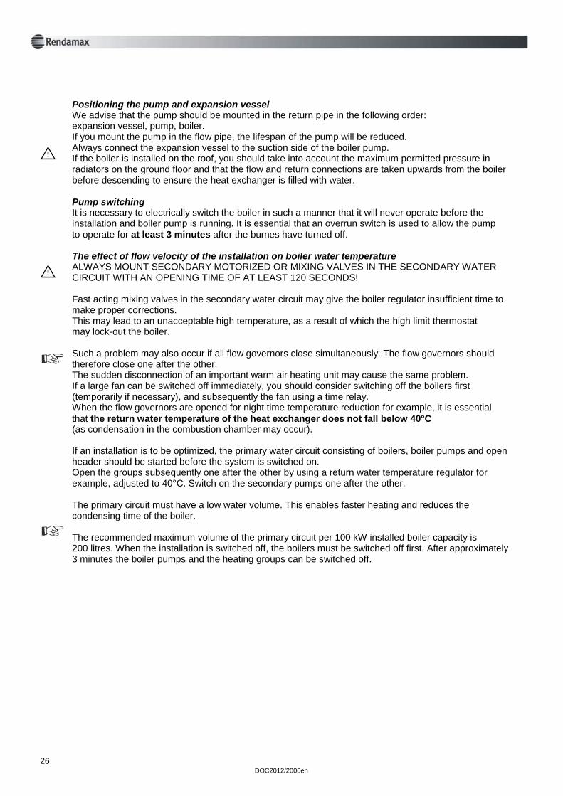
Fig. 15 R2000 unit with outside temperature compensation
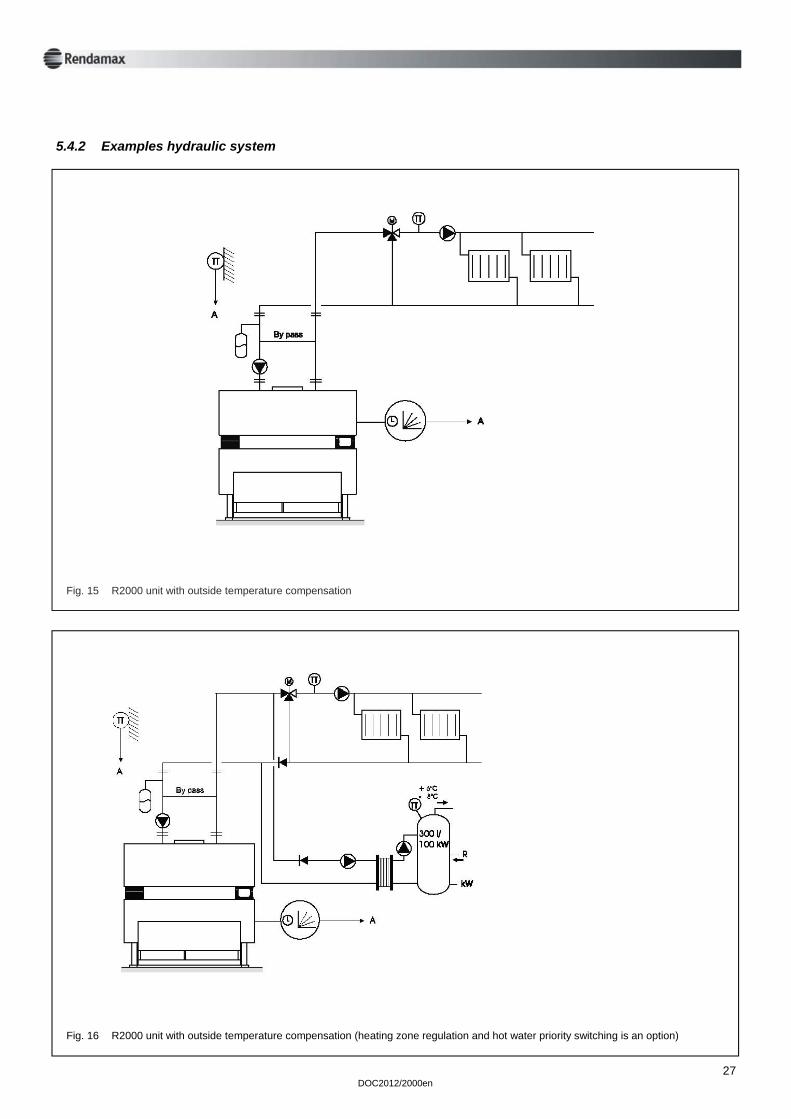
5.4.2 Examples hydraulic system
Fig. 16 R2000 unit with outside temperature compensation (heating zone regulation and hot water priority switching is an option)
28 DOC2012/2000en
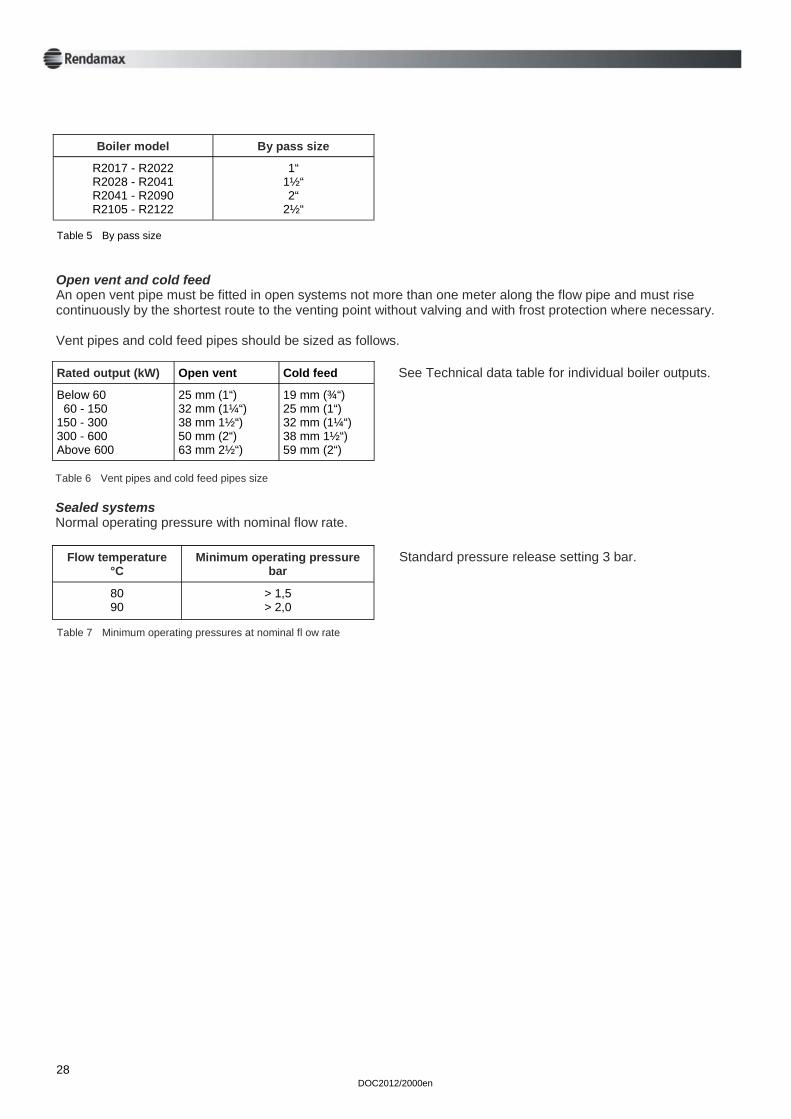
Open vent and cold feed An open vent pipe must be fitted in open systems not more than one meter along the flow pipe and must rise continuously by the shortest route to the venting point without valving and with frost protection where necessary. Vent pipes and cold feed pipes should be sized as follows.
Rated output (kW) Open vent Cold feed
Below 60 60 - 150 150 - 300 300 - 600 Above 600
25 mm (1“) 32 mm (1¼“) 38 mm 1½“) 50 mm (2“) 63 mm 2½“)
19 mm (¾“) 25 mm (1“) 32 mm (1¼“) 38 mm 1½“) 59 mm (2“)
See Technical data table for individual boiler outputs.
Table 6 Vent pipes and cold feed pipes size Sealed systems Normal operating pressure with nominal flow rate.
Flow temperature °C
Minimum operating pressure bar
80 90
> 1,5 > 2,0
Standard pressure release setting 3 bar.
Table 7 Minimum operating pressures at nominal fl ow rate
Boiler model By pass size
R2017 - R2022 R2028 - R2041 R2041 - R2090 R2105 - R2122
1“ 1½“ 2“
2½“
Table 5 By pass size
DOC2012/2000en
29
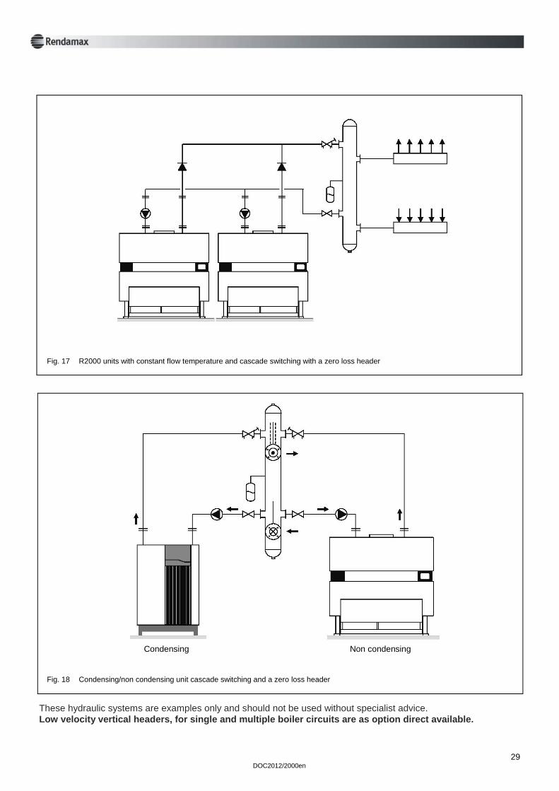
These hydraulic systems are examples only and should not be used without specialist advice. Low velocity vertical headers, for single and multiple boiler circuits are as option direct available.
Fig. 17 R2000 units with constant flow temperature and cascade switching with a zero loss header
Fig. 18 Condensing/non condensing unit cascade switching and a zero loss header
Condensing Non condensing
30 DOC2012/2000en
6 Commissioning 6.1 General COMMISSIONING OF THE BOILER MUST BE CARRIED OUT BY PROPERLY QUALIFIED AND AUTHORISED PERSONNEL. OTHERWISE, THE GUARANTY WILL BECOME VOID. Never deviate from the instructions in this manual. Flushing the system To prevent damage from rust, sealing compounds, sand, metal particles etc., the system must be flushed thoroughly, before the system is switched on. Also ensure that the heat exchanger is free of any such deposits after flushing the system. Water heating system - fill the system up to the standard set pressure - bleeding the system - switch on all pumps and check for correct direction of rotation - close the stop-valves in the secondary groups
Electrical connection - check the boiler electrical connection - switch on the boiler with the ON/OFF switch - adjust the temperature regulator to the desired flow water temperature Gas connection - open the gas service cocks - bleed the gas pipe NB: Insure adequate ventilation during bleeding - connect the measuring equipment to check: * static pressure * burner pressure * boiler ionisation current
DOC2012/2000en
31
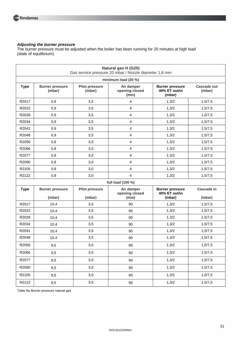
Adjusting the burner pressure The burner pressure must be adjusted when the boiler has been running for 20 minutes at high load (state of equilibrium).
Natural gas H (G20) Gas service pressure 20 mbar / Nozzle diameter 1,8 mm
minimum load (20 %)
Type Burner pressure (mbar)
Pilot pressure (mbar)
Air damper opening closed
(mm)
Cascade out (mbar)
R2017 0,9 3,5 4 1,5/7,5
R2022 0,9 3,5 4 1,5/7,5
R2028 0,9 3,5 4 1,5/7,5
R2034 0,9 3,5 4 1,5/7,5
R2041 0,9 3,5 4 1,5/7,5
R2048 0,9 3,5 4 1,5/7,5
Type Burner pressure
(mbar)
Pilot pressure
(mbar)
Air damper opening closed
(mm)
Cascade in
(mbar)
R2017 10,4 3,5 90 1,5/7,5
R2022 10,4 3,5 90 1,5/7,5
R2028 10,4 3,5 90 1,5/7,5
R2034 10,4 3,5 90 1,5/7,5
R2041 10,4 3,5 90 1,5/7,5
R2048 10,4 3,5 90 1,5/7,5
full load (100 %)
Burner pressure 40% ET out/in
(mbar)
1,3/2
1,3/2
1,3/2
1,3/2
1,3/2
1,3/2
Burner pressure 40% ET out/in
(mbar)
1,3/2
1,3/2
1,3/2
1,3/2
1,3/2
1,3/2
R2056 0,8 3,0 4 1,3/2 1,5/7,5
R2066 0,8 3,0 4 1,3/2 1,5/7,5
R2077 0,8 3,0 4 1,3/2 1,5/7,5
R2090 0,8 3,0 4 1,3/2 1,5/7,5
R2105 0,8 3,0 4 1,3/2 1,5/7,5
R2122 0,8 3,0 4 1,3/2 1,5/7,5
R2056 9,5 3,0 90 1,3/2 1,5/7,5
R2066 9,5 3,0 90 1,3/2 1,5/7,5
R2077 9,5 3,0 90 1,3/2 1,5/7,5
R2090 9,5 3,0 90 1,3/2 1,5/7,5
R2105 9,5 3,0 90 1,3/2 1,5/7,5
R2122 9,5 3,0 90 1,3/2 1,5/7,5
Table 8a Burner pressure natural gas
32 DOC2012/2000en
Liquid Propane Gas Gas service pressure 50 mbar
Nozzle diameter 1 mm
minimum load (20 %)
Type Burner pressure start/min.
(mbar)
Pilot pressure
(mbar)
Air damper opening closed
(mm)
Cascade out
(mbar)
R2017 5/2 11 8 6/28
R2022 5/2 11 8 6/28
R2028 5/2 11 8 6/28
R2034 5/2 11 8 6/28
R2041 5/2 11 8 6/28
R2048 5/2 11 8 6/28
Type Burner pressure
(mbar)
Pilot pressure
(mbar)
Air damper opening open
(mm)
Cascade in
(mbar)
R2017 40 11 90 6/28
R2022 40 11 90 6/28
R2028 40 11 90 6/28
R2034 40 11 90 6/28
R2041 40 11 90 6/28
R2048 40 11 90 6/28
full load (100 %)
Burner pressure 40% ET out
(mbar)
13/18
13/18
13/18
13/18
13/18
13/18
Burner pressure 40% ET out
(mbar)
13/18
13/18
13/18
13/18
13/18
13/18
R2056 5/2 11 8 13/18 6/28
R2066 5/2 11 8 13/18 6/28
R2077 5/2 11 8 13/18 6/28
R2090 5/2 11 8 13/18 6/28
R2105 5/2 11 8 13/18 6/28
R2122 5/2 11 8 13/18 6/28
R2056 40 11 90 13/18 6/28
R2066 40 11 90 13/18 6/28
R2077 40 11 90 13/18 6/28
R2090 40 11 90 13/18 6/28
R2105 40 11 90 13/18 6/28
R2122 40 11 90 13/18 6/28
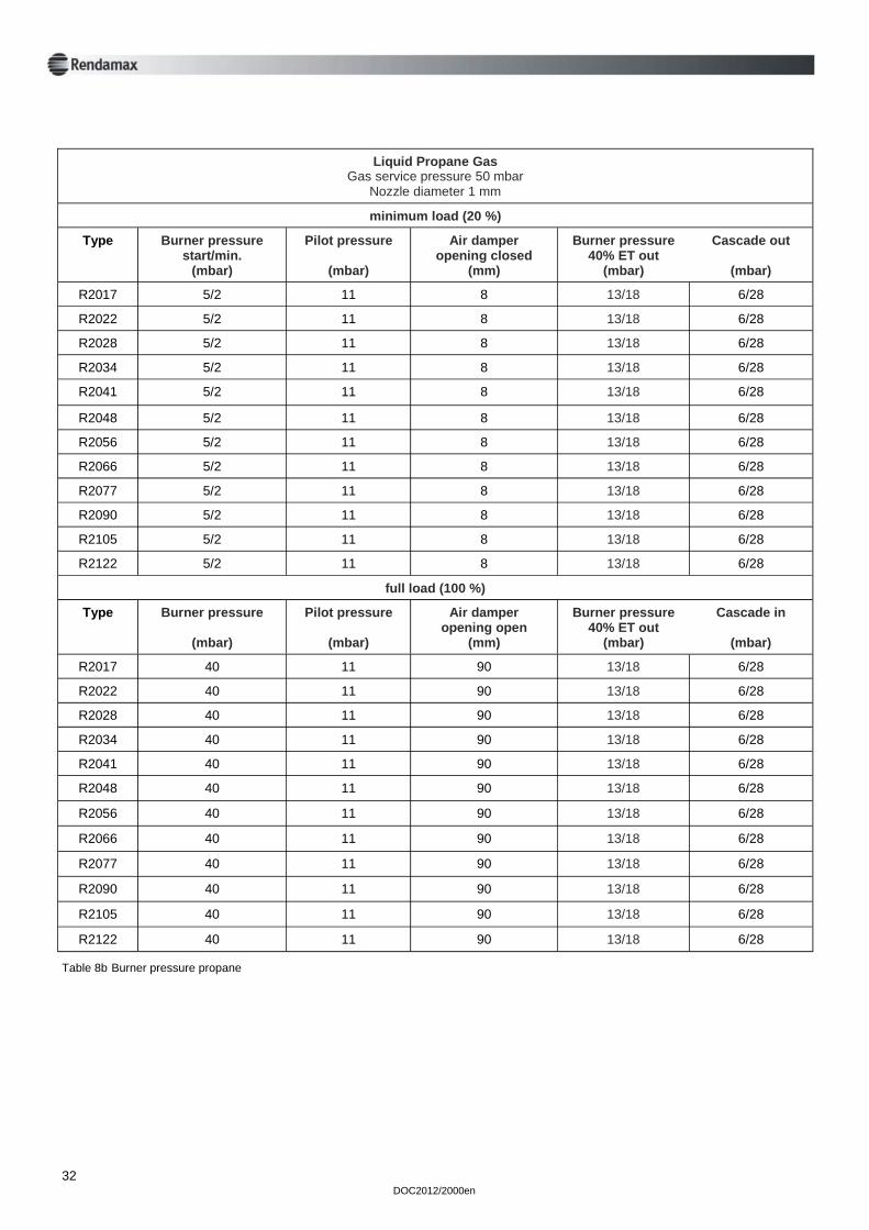
Table 8b Burner pressure propane
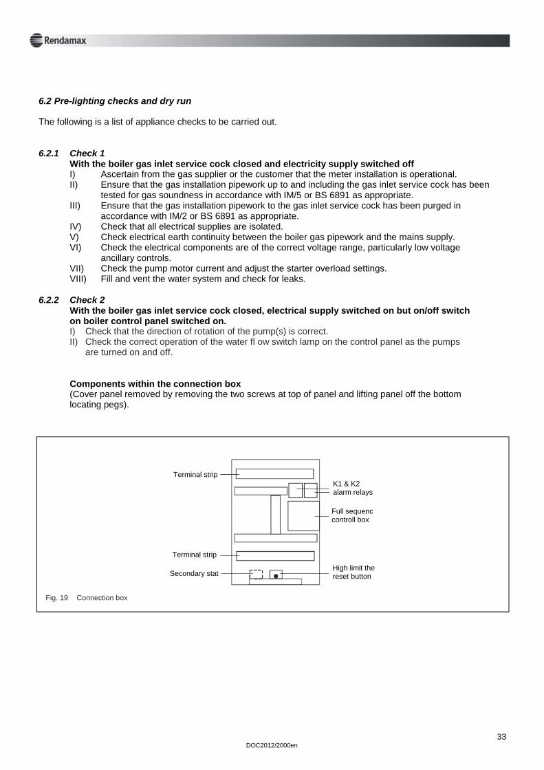
6.2 Pre-lighting checks and dry run The following is a list of appliance checks to be carried out. 6.2.1 Check 1 With the boiler gas inlet service cock closed and electricity supply switched off I) Ascertain from the gas supplier or the customer that the meter installation is operational. II) Ensure that the gas installation pipework up to and including the gas inlet service cock has been tested for gas soundness in accordance with IM/5 or BS 6891 as appropriate. III) Ensure that the gas installation pipework to the gas inlet service cock has been purged in accordance with IM/2 or BS 6891 as appropriate. IV) Check that all electrical supplies are isolated. V) Check electrical earth continuity between the boiler gas pipework and the mains supply. VI) Check the electrical components are of the correct voltage range, particularly low voltage ancillary controls. VII) Check the pump motor current and adjust the starter overload settings. VIII) Fill and vent the water system and check for leaks. 6.2.2 Check 2 With the boiler gas inlet service cock closed, electrical supply switched on but on/off switch on boiler control panel switched on. I) Check that the direction of rotation of the pump(s) is correct. II) Check the correct operation of the water fl ow switch lamp on the control panel as the pumps are turned on and off. Components within the connection box (Cover panel removed by removing the two screws at top of panel and lifting panel off the bottom locating pegs).
DOC2012/2000en
33
Fig. 19 Connection box
Terminal strip
Terminal strip
Secondary stat
K1 & K2 alarm relays
Full sequenc controll box
High limit the reset button
34 DOC2012/2000en
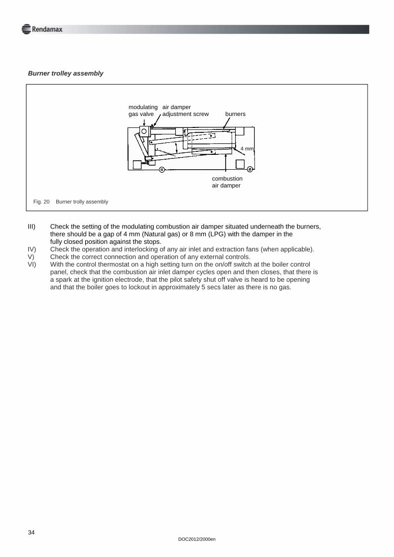
Burner trolley assembly
Fig. 20 Burner trolly assembly
III) Check the setting of the modulating combustion air damper situated underneath the burners, there should be a gap of 4 mm (Natural gas) or 8 mm (LPG) with the damper in the fully closed position against the stops. IV) Check the operation and interlocking of any air inlet and extraction fans (when applicable). V) Check the correct connection and operation of any external controls. VI) With the control thermostat on a high setting turn on the on/off switch at the boiler control panel, check that the combustion air inlet damper cycles open and then closes, that there is a spark at the ignition electrode, that the pilot safety shut off valve is heard to be opening and that the boiler goes to lockout in approximately 5 secs later as there is no gas.
modulating air damper gas valve adjustment screw burners
combustion air damper
4 mm
DOC2012/2000en
35
6.2.3 Check 3 With the electricity supply switched off check the gas train downstream of the gas inlet service cock as follows: Refer to Gas trains, fig. 28 for particular boiler model. 1. Ensure that gas service cock and pilot manual cock are closed. 2. Connect a pressure gauge to test point 10/1 and open test point 10/2. 3. Open and then close the gas service cock to pressurise up to the 1st safety shut off valve. 4. Allow 1 min. for temperature stabilisation and then check for any loss of pressure during the next 2 mins. 5. If there is a pressure loss the pipework up stream of the 1st safety shut off valve should be checked with a suitable leak detection fl uid with the gas service cock open. 6. If no leak is found, this indicates that the 1st safety shut off valve is letting by and should be replaced (whole multi block on models R2017 and R2022). 7. With test points 10/1 and 10/2 opened connect them together with a short piece of fl exible tubing which incorporates a tee connection to the pressure gauge. 8. Open and close the gas service cock to pressurise up to the 2nd safety shut off valve. 9. Allow 1 min. for temperature stabilisation and then check for any loss of pressure at the gauge during the next 2 minutes. 10. If there is a pressure loss the pipework between the 1st and 2nd safety shut off valve should be checked with a suitable leak detection fl uid with the gas service cock open. (Not applicable to models R2017 and R2022). 11. If no leak is found this indicates that the 2nd safety shut off valve is letting by and should be replaced (whole multi block on models R2017 and R2022).
a) Disconnect the electrical connections to the 1st safety shut off valves by removing the plug from the front electrical panel. (valve 4a fig. 29). Open the gas service cock and pilot manual cock and with the control thermostat on a high setting turn on the electrical supply and the on/off switch on the front control panel. Check that the combustion air inlet damper cycles to the fully open position and back before ignition of the pilot burner commences. Using the sight glass at the lower right hand side of the boiler check that the ignition electrode ignites the pilot burner and that the pilot burner is stable in operation. b) Disconnect the electrical connection to the 2nd safety shut off valve by removing the electrical connector from the front, electrical tray. Check that the boiler goes to lockout approximately 5 secs later and that the pilot burner is extinguished. (It may be necessary to purge the ignition system if there is air in the gas supply; although seven minutes must be allowed between each attempt to ensure that any gas has been dispersed from the combustion chamber). Press reset button to override boiler lockout the pilot pipe and connections from the pilot manual cock to the burner connection or gas sound. c) Connect a pressure gauge to pressure test point 10/3 (see gas train fig. 28) and carry out a) above. Check that pilot burner pressure is as indicated in table 8a or 8b, with the pilot burner on test the pilot pipe and connections to the burner.
6.3 Live run check
36 DOC2012/2000en
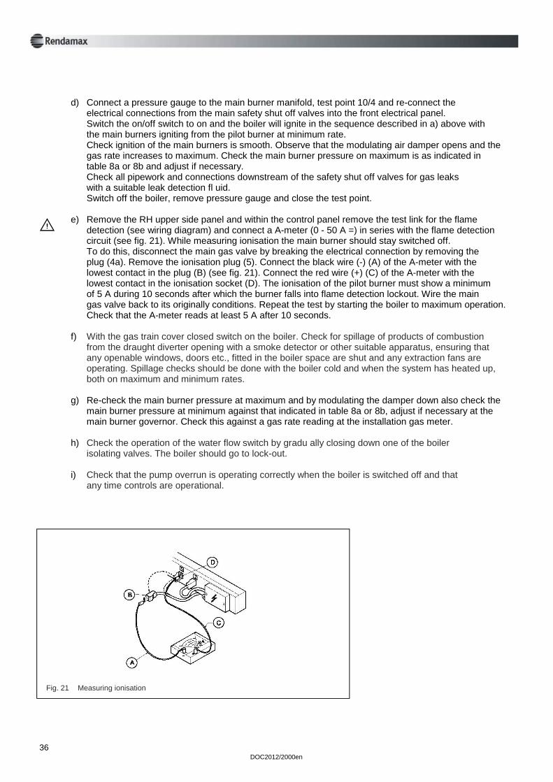
d) Connect a pressure gauge to the main burner manifold, test point 10/4 and re-connect the electrical connections from the main safety shut off valves into the front electrical panel. Switch the on/off switch to on and the boiler will ignite in the sequence described in a) above with the main burners igniting from the pilot burner at minimum rate. Check ignition of the main burners is smooth. Observe that the modulating air damper opens and the gas rate increases to maximum. Check the main burner pressure on maximum is as indicated in table 8a or 8b and adjust if necessary. Check all pipework and connections downstream of the safety shut off valves for gas leaks with a suitable leak detection fl uid. Switch off the boiler, remove pressure gauge and close the test point. e) Remove the RH upper side panel and within the control panel remove the test link for the flame detection (see wiring diagram) and connect a A-meter (0 - 50 A =) in series with the flame detection circuit (see fig. 21). While measuring ionisation the main burner should stay switched off. To do this, disconnect the main gas valve by breaking the electrical connection by removing the plug (4a). Remove the ionisation plug (5). Connect the black wire (-) (A) of the A-meter with the lowest contact in the plug (B) (see fig. 21). Connect the red wire (+) (C) of the A-meter with the lowest contact in the ionisation socket (D). The ionisation of the pilot burner must show a minimum of 5 A during 10 seconds after which the burner falls into flame detection lockout. Wire the main gas valve back to its originally conditions. Repeat the test by starting the boiler to maximum operation. Check that the A-meter reads at least 5 A after 10 seconds. f) With the gas train cover closed switch on the boiler. Check for spillage of products of combustion from the draught diverter opening with a smoke detector or other suitable apparatus, ensuring that any openable windows, doors etc., fitted in the boiler space are shut and any extraction fans are operating. Spillage checks should be done with the boiler cold and when the system has heated up, both on maximum and minimum rates. g) Re-check the main burner pressure at maximum and by modulating the damper down also check the main burner pressure at minimum against that indicated in table 8a or 8b, adjust if necessary at the main burner governor. Check this against a gas rate reading at the installation gas meter. h) Check the operation of the water flow switch by gradu ally closing down one of the boiler isolating valves. The boiler should go to lock-out. i) Check that the pump overrun is operating correctly when the boiler is switched off and that any time controls are operational.
E
Fig. 21 Measuring ionisation
Upon satisfactory completion of commissioning hand the Technical documentation to the person responsible for the plant and explain the method of safe operation. Ensure that he/she is fully conversant with the starting, shut down, general operation and emergency shut down procedures. Explain the operation of the overheat control, by pressing button in right hand upper side panel, but stress that in case of repeated overheating of the boiler that the fault should be corrected by a competent person. Stress the importance of regular servicing for safe and efficient operation and that if a gas leak is detected to turn off the boiler at the gas service cock and to call the local gas supplier. Boiler failure In case of boiler failure the system will fall into lock-out. Reset the boiler with the reset button on the control panel. Repeat this several times if necessary. If the boiler still does not start, refer to chapter ‘Operation and fault finding’ (7).
6.4 Instructions to user
DOC2012/2000en
37
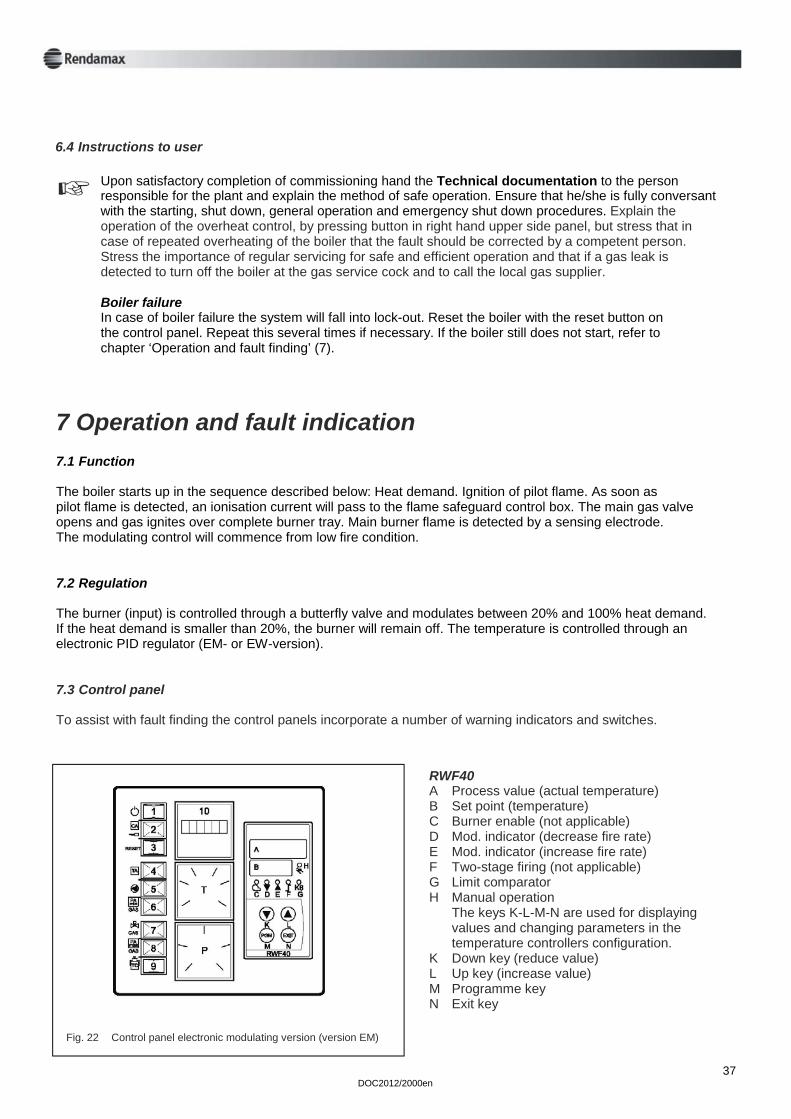
7 Operation and fault indication 7.1 Function The boiler starts up in the sequence described below: Heat demand. Ignition of pilot flame. As soon as pilot flame is detected, an ionisation current will pass to the flame safeguard control box. The main gas valve opens and gas ignites over complete burner tray. Main burner flame is detected by a sensing electrode. The modulating control will commence from low fire condition. 7.2 Regulation The burner (input) is controlled through a butterfly valve and modulates between 20% and 100% heat demand. If the heat demand is smaller than 20%, the burner will remain off. The temperature is controlled through an electronic PID regulator (EM- or EW-version). 7.3 Control panel To assist with fault finding the control panels incorporate a number of warning indicators and switches.
Fig. 22 Control panel electronic modulating version (version EM)
RWF40 A Process value (actual temperature) B Set point (temperature) C Burner enable (not applicable) D Mod. indicator (decrease fire rate) E Mod. indicator (increase fire rate) F Two-stage firing (not applicable) G Limit comparator H Manual operation The keys K-L-M-N are used for displaying values and changing parameters in the temperature controllers configuration. K Down key (reduce value) L Up key (increase value) M Programme key N Exit key
DOC2012/2000en
If there is insufficient water flow the boiler will turn off and lock- out. Red lamps 2 and 5 on. Reset by pushing button 3 If the flow temperature exceeds the high limit setting, the boiler will mechanically lock out and red lamp 2 illuminates. Reset by pushing button 3 and allow the unit to fire. If lamp 4 TA then illuminates, reset button in high limit thermostat. Remove the two screws at the top of the upper right hand panel. Remove the panel by lifting up. Remove the high limit thermostat cap nut (see sticker high limit thermo- stat) with a 17 mm ring spanner. (See fig. 19) Press a screwdriver against the green peg until a light click is heard. Lamp 4 turns off. Refit capnut. Refi tupper right hand panel and fasten the two top screws. Then press button 3 to reset red lamp 2 (CA). If an ionisation interruption occurs, red lamp 2 will light, burner will be off. Reset by pushing reset button 3. The pilot flame on the main burner can be observed through the sight glass on the lower right hand side of the boiler (see pos. 12, fig. 2).
7.4 Fault indications
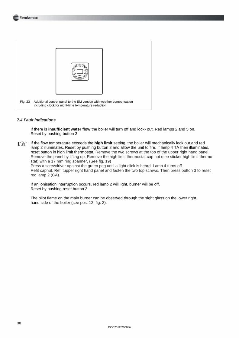
Fig. 23 Additional control panel to the EM version with weather compensation including clock for night-time temperature reduction
38
DOC2012/2000en 39
Ensure that gas and electric supplies are connected. Start sequence: A Turn manual gas cock open B Turn the pumps on C Ensure that all hot water outlets are closed D Turn the supply voltage to the boiler on and turn the boiler on using the power switch 1 E In case of failure, observe type of failure, take necessary steps to rectify, refer to section 4 for details F Set temperature regulator as required.
7.5 Start-up
A To turn off for short periods switch boiler off by using the power switch 1 B For long periods switch the pump off and after 6 minutes close the main gas cock and main electrical supply.
7.6 Shut-down
Non operation of boiler during the winter time can cause freezing. By draining the water out of the heat exchanger, using the drain taps mounted on the under-side of the flow and return header manifold. Damage to boiler will then be avoided. WARNING In case of failure obtain assistance from a qualifi ed CORGI gas/heating engineer. Don’t repair yourself.
7.7 Warnings
DOC2012/2000en 40
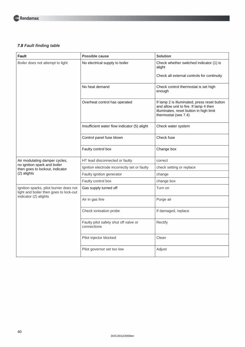
Fault Possible cause Solution
Boiler does not attempt to light No electrical supply to boiler Check whether switched indicator (1) is alight Check all external controls for continuity
No heat demand Check control thermostat is set high enough
Overheat control has operated If lamp 2 is illuminated, press reset button and allow unit to fire. If lamp 4 then illuminates, reset button in high limit thermostat (see 7.4)
Insufficient water flow indicator (5) alight Check water system
Control panel fuse blown Check fuse
Faulty control box Change box
Air modulating damper cycles, no ignition spark and boiler then goes to lockout, indicator (2) alights
HT lead disconnected or faulty correct
Ignition electrode incorrectly set or faulty check setting or replace
Faulty ignition generator change
Faulty control box change box
Gas supply turned off
Turn on
Air in gas line
Purge air
Check ionisation probe
If damaged, replace
Faulty pilot safety shut off valve or connections
Rectify
Pilot injector blocked
Clean
Pilot governor set too low
Adjust
Ignition sparks, pilot burner does not light and boiler then goes to lock-out indicator (2) alights
7.8 Fault finding table
DOC2012/2000en 41
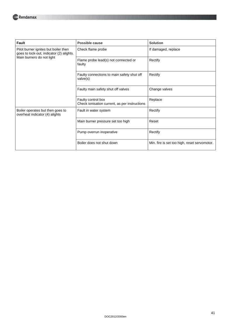
Fault Possible cause Solution
Pilot burner ignites but boiler then goes to lock-out, indicator (2) alights. Main burners do not light
Check flame probe
If damaged, replace
Flame probe lead(s) not connected or faulty
Rectify
Faulty connections to main safety shut off valve(s)
Rectify
Faulty main safety shut off valves
Change valves
Faulty control box Check ionisation current, as per instructions
Replace
Boiler operates but then goes to overheat indicator (4) alights
Fault in water system
Rectify
Main burner pressure set too high
Reset
Pump overrun inoperative
Rectify
Boiler does not shut down Min. fire is set too high, reset servomotor.
DOC2012/2000en 42
8 Maintenance
Always wear the proper protective clothing and shoes when servicing the boiler. Wearing jewelry and loose clothing can contribute to unsafe situations.
8.1 Safety
In order to keep the R2000 in a safe working condition, the boiler should be inspected and serviced at least once every year and cleaned if necessary. Frost protection When boiler is not in operation for a long period of time, the heat exchanger should be protected against frost. This can be achieved by draining water from the heat exchanger.
8.2 General information
E
Inspecting the draught diverter Remove the inner and outer access panels on the draught diverter to allow internal inspection of the draught diverter and flue baffles. Heat exchanger (external inspection) As you inspect the inside of the draught diverter, the top of the heat exchanger can also be inspected. Check for dirt and sooting. For cleaning the heat exchanger, refer to chapter “Cleaning”. After removing the burner, the combustion chamber and the underside of the heat exchanger can easily be inspected by using a mirror for example. Heat exchanger (internal inspection) Internal inspection must be carried out by qualified and authorised personnel. Sight glass A sight glass can be found on the right hand side of the burner assembly for inspection of: - boiler ignition - combustion - pilot flame. Burner tray The burner manifold and the gas regulator are connected by means of a coupling. Remove the burner for inspection as follows: 1 Close the gas service cock and disconnect the burner manifold and gas regulator 2 Release the two brackets which attach the burner to the boiler frame. 3 Disconnect the spark plug, ionisation caps, servo-motor plugs and solenoid value plugs and remove the ‘earth’ lead. 4 Carefully withdraw the burner from the boiler unit. Inspect for dirt and clean the burner bars if necessary.
8.3 Inspection
E
DOC2012/2000en
Before using chemicals and cleaning agents in the boiler, please contact your supplier for advise.
Always read the instructions on the bottle of the cleaning agents before using them. Heat exchanger (external cleaning) Remove the baffles before cleaning the heat exchanger. - Use compressed air when the heat exchanger is lightly soiled - Use a stiff brush and soap when the heat exchanger is very dirty, do not allow the refractory brick-work to get wet. NB. The heat exchanger may become heavily soiled (soot for example), when the instructions are not followed properly. This may be caused by: - insufficient ventilation - condensate on the heat exchanger. If this is the case, clean the complete heat exchanger, including the baffles. Furthermore, the cause of the problem should be ascertained and rectified. Heat exchanger (internal cleaning) Descale the heat exchanger with suitable chemicals. Filter inspection When the pressure loss over the gas regulator gets too high, the burner pressure will decrease noticeably. A dirty gas filter may be the cause. The filter should be inspected at least once every year. To allow access to the filter element, first remove the side cover of the gas regulator assembly. Then remove the filter and replace it if necessary. Replace the cover and check for leaks.
8.4 Cleaning
43
WARNING: ONLY COMPETENT PERSONS SHOULD CARRY OUT SERVICING ON THIS BOILER IN ACCORDANCE WITH THE GAS SAFETY (INSTALLATION AND USE) REGULATIONS 1984. Ensure that both gas and electrical supplies are switched off before carrying out any service operation. After carrying out any service operation it is important to check for gas soundness and re-commission the boiler as described in Section 6 - Commissioning. Ensure that any panels covering live connections are replaced securely upon completing any service operation. Wiring diagrams and components lists are supplied separately. Routine maintenance The frequency of routine maintenance depends on the use and environment in which the boiler is used although it must be carried out at least annually. The scope of routine maintenance includes the following: I Cleaning the heat exchanger II Cleaning the burner assembly and inspect the condition of the burner and ignition components III Checking the gas train for soundness IV Inspecting the adjustment of the air damper and operation of the modulating gas valve and servo-motor V Checking the effectiveness of natural or mechanical ventilation VI Inspecting the flue system including terminal, for damage and ensure it is evacuating the products of combustion without any leakage or spillage VII Check gas pressure settings, safety lock-out systems and water flow switch VIII Inspect condition of refractory lining.
8.5 Servicing
E
DOC2012/2000en 44
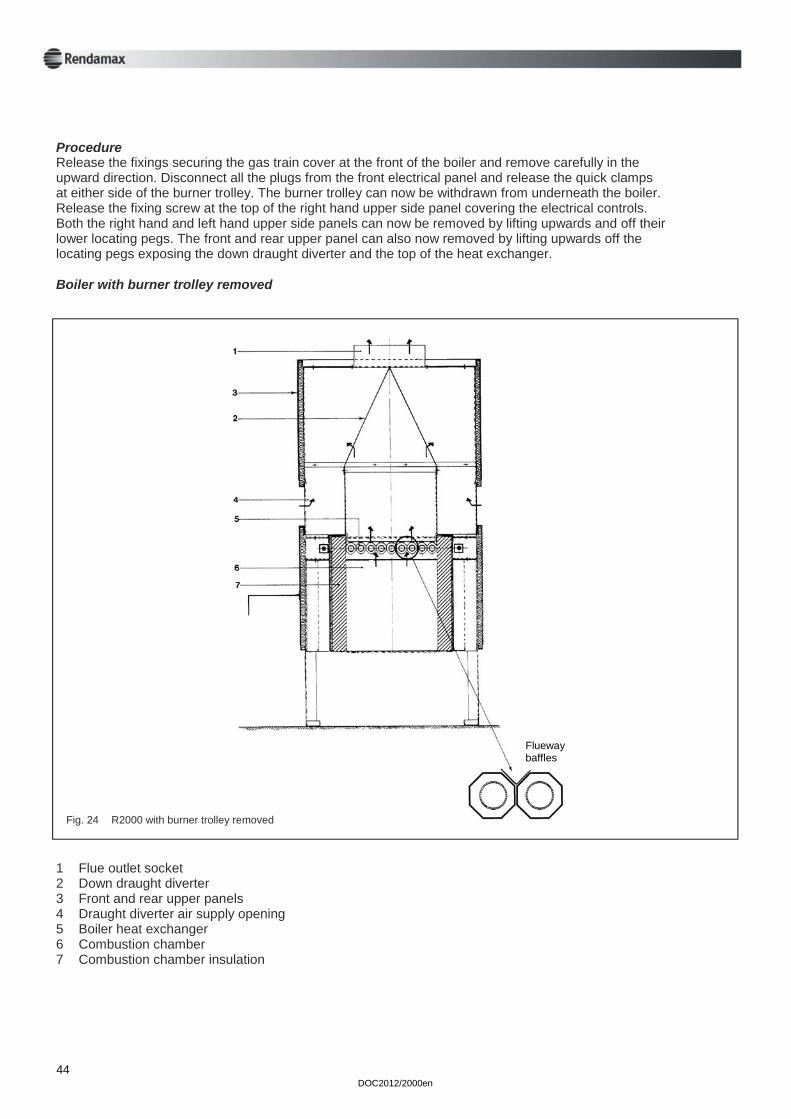
Procedure Release the fixings securing the gas train cover at the front of the boiler and remove carefully in the upward direction. Disconnect all the plugs from the front electrical panel and release the quick clamps at either side of the burner trolley. The burner trolley can now be withdrawn from underneath the boiler. Release the fixing screw at the top of the right hand upper side panel covering the electrical controls. Both the right hand and left hand upper side panels can now be removed by lifting upwards and off their lower locating pegs. The front and rear upper panel can also now removed by lifting upwards off the locating pegs exposing the down draught diverter and the top of the heat exchanger. Boiler with burner trolley removed
Fig. 24 R2000 with burner trolley removed
1 Flue outlet socket 2 Down draught diverter 3 Front and rear upper panels 4 Draught diverter air supply opening 5 Boiler heat exchanger 6 Combustion chamber 7 Combustion chamber insulation
Flueway baffles
DOC2012/2000en 45
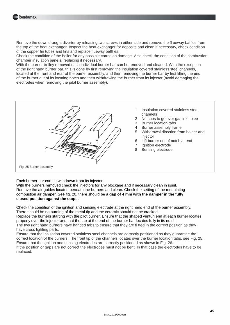
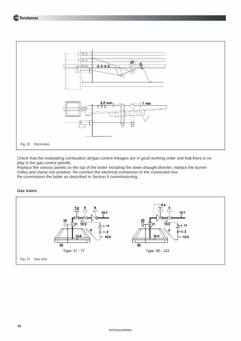
Each burner bar can be withdrawn from its injector. With the burners removed check the injectors for any blockage and if necessary clean in spirit. Remove the air guides located beneath the burners and clean. Check the setting of the modulating combustion air damper. See fig. 20, there should be a gap of 4 mm with the damper in the fully closed position against the stops. Check the condition of the ignition and sensing electrode at the right hand end of the burner assembly. There should be no burning of the metal tip and the ceramic should not be cracked. Replace the burners starting with the pilot burner. Ensure that the shaped venturi end at each burner locates properly over the injector and that the tab at the end of the burner bar locates fully in its notch. The two right hand burners have handed tabs to ensure that they are fi tted in the correct position as they have cross lighting parts. Ensure that the insulation covered stainless steel channels are correctly positioned as they guarantee the correct location of the burners. The front tip of the channels locates over the burner location tabs, see Fig. 25. Ensure that the ignition and sensing electrodes are correctly positioned as shown in Fig. 26. If the position or gaps are not correct the electrodes must not be bent. In that case the electrodes have to be replaced.
Remove the down draught diverter by releasing two screws in either side and remove the fl ueway baffles from the top of the heat exchanger. Inspect the heat exchanger for deposits and clean if necessary, check condition of the copper fin tubes and fins and replace flueway baffl es. Check the condition of the boiler for any possible corrosion damage. Also check the condition of the combustion chamber insulation panels, replacing if necessary. With the burner trolley removed each individual burner bar can be removed and cleaned. With the exception of the right hand burner bar, this is done by first removing the insulation covered stainless steel channels, located at the front and rear of the burner assembly, and then removing the burner bar by first lifting the end of the burner out of its locating notch and then withdrawing the burner from its injector (avoid damaging the electrodes when removing the pilot burner assembly).
Fig. 25 Burner assembly
1 Insulation covered stainless steel channels 2 Notches to go over gas inlet pipe 3 Burner location tabs 4 Burner assembly frame 5 Withdrawal direction from holder and injector 6 Lift burner out of notch at end 7 Ignition electrode 8 Sensing electrode
DOC2012/2000en 46
Fig. 26 Electrodes
Check that the modulating combustion air/gas control linkages are in good working order and that there is no play in the gas control spindle. Replace the various panels on the top of the boiler including the down draught diverter, replace the burner trolley and clamp into position. Re-connect the electrical connectors to the connection box. Re-commission the boiler as described in Section 6 commissioning. Gas trains
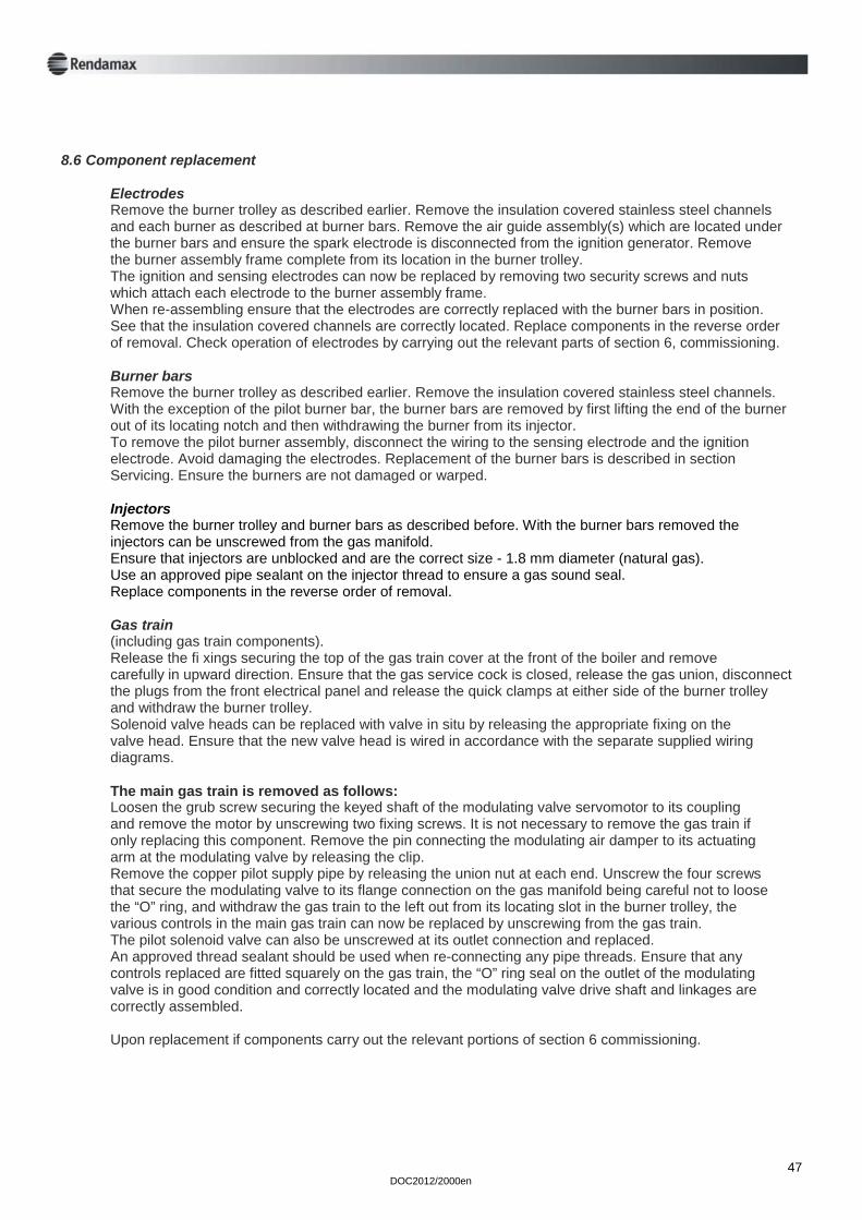
Fig. 27 Gas train
Type: 17 - 77 Type: 90 - 122
Electrodes Remove the burner trolley as described earlier. Remove the insulation covered stainless steel channels and each burner as described at burner bars. Remove the air guide assembly(s) which are located under the burner bars and ensure the spark electrode is disconnected from the ignition generator. Remove the burner assembly frame complete from its location in the burner trolley. The ignition and sensing electrodes can now be replaced by removing two security screws and nuts which attach each electrode to the burner assembly frame. When re-assembling ensure that the electrodes are correctly replaced with the burner bars in position. See that the insulation covered channels are correctly located. Replace components in the reverse order of removal. Check operation of electrodes by carrying out the relevant parts of section 6, commissioning. Burner bars Remove the burner trolley as described earlier. Remove the insulation covered stainless steel channels. With the exception of the pilot burner bar, the burner bars are removed by first lifting the end of the burner out of its locating notch and then withdrawing the burner from its injector. To remove the pilot burner assembly, disconnect the wiring to the sensing electrode and the ignition electrode. Avoid damaging the electrodes. Replacement of the burner bars is described in section Servicing. Ensure the burners are not damaged or warped. Injectors Remove the burner trolley and burner bars as described before. With the burner bars removed the injectors can be unscrewed from the gas manifold. Ensure that injectors are unblocked and are the correct size - 1.8 mm diameter (natural gas). Use an approved pipe sealant on the injector thread to ensure a gas sound seal. Replace components in the reverse order of removal. Gas train (including gas train components). Release the fi xings securing the top of the gas train cover at the front of the boiler and remove carefully in upward direction. Ensure that the gas service cock is closed, release the gas union, disconnect the plugs from the front electrical panel and release the quick clamps at either side of the burner trolley and withdraw the burner trolley. Solenoid valve heads can be replaced with valve in situ by releasing the appropriate fixing on the valve head. Ensure that the new valve head is wired in accordance with the separate supplied wiring diagrams. The main gas train is removed as follows: Loosen the grub screw securing the keyed shaft of the modulating valve servomotor to its coupling and remove the motor by unscrewing two fixing screws. It is not necessary to remove the gas train if only replacing this component. Remove the pin connecting the modulating air damper to its actuating arm at the modulating valve by releasing the clip. Remove the copper pilot supply pipe by releasing the union nut at each end. Unscrew the four screws that secure the modulating valve to its flange connection on the gas manifold being careful not to loose the “O” ring, and withdraw the gas train to the left out from its locating slot in the burner trolley, the various controls in the main gas train can now be replaced by unscrewing from the gas train. The pilot solenoid valve can also be unscrewed at its outlet connection and replaced. An approved thread sealant should be used when re-connecting any pipe threads. Ensure that any controls replaced are fitted squarely on the gas train, the “O” ring seal on the outlet of the modulating valve is in good condition and correctly located and the modulating valve drive shaft and linkages are correctly assembled. Upon replacement if components carry out the relevant portions of section 6 commissioning.
8.6 Component replacement
DOC2012/2000en 47
DOC2012/2000en 48
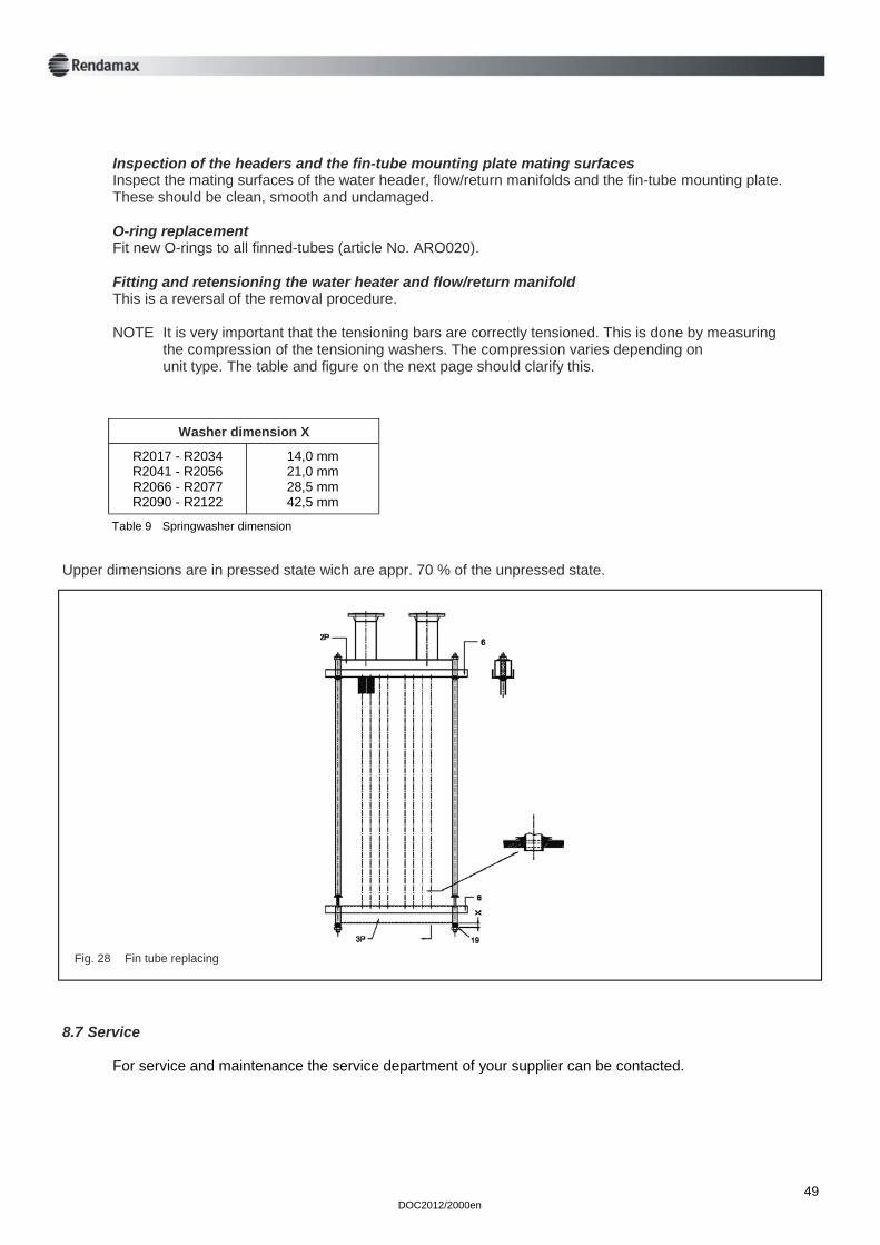
Ignition generator Release the two fixings securing the top of the gas train cover at the front of the boiler and remove carefully in upward direction. Disconnect all of the plugs from the front electrical panel and remove the cover of the electrical panel by releasing two screws at each end. Disconnect the ignition generator electrical connection from within the control panel and release the ignition electrode lead from the generator. Replace the generator by releasing its screw fitting and reconnect the electrical connections in accordance with the separate supplied wiring diagrams. Control panel components Release the two fixing screws at the top of the right hand upper side panel and remove the panel by lifting upwards and off its lower locating pegs. Refer to fig. 19 for the locations of the various controls. Replace components by removing electrical connections and screw fixings. It is necessary to drain the boiler when replacing the water flow switch as it incorporates water connections. The temperature sensing phials for both the control thermostat and the overheat control are contained within a thermostat pocket in the flow header immediately beneath the control panel. The phials are released by first removing the securing clip. The control thermostat is fixed to the front right hand side panel of the boiler and its fixing screws can be accessed via the control panel. Re-connect any electrical connections in accordance with the separate supplied wiring diagrams. Replacing fin tubes Header and manifold removal Release water pressure and drain the unit. Disconnect the system water-pipes at the manifold flanges. Disconnect all pressure and temperature sensors from the flow/return header and electrically disconnect the flow-switch. Remove the heat exchanger tensioning bars. Carefully remove the water manifold and flow/return header (2P and 3P). Fin tube replacement Remove the unit’s 18 O-rings. From the top of the heat exchanger remove two baffles, one on either side of the damaged finned-tube. On the side of the unit with the best access, remove the 4 bolts which attach the finned-tube mounting-plate (6) the unit’s frame. This will allow partial withdrawal of the finned-tube mounting plate. Insert the 9 special tools into the finned-tubes on this side of the unit. Gently withdraw the finned-tube mounting plate (6) about 3” and remove the special tool from the damaged fin tube. It should now be possible to remove this finned-tube from within the unit while the remaining tubes remain in position. During this operation the finned-tube mounting plate at the other end of the unit need not be moved. Fit the replacement finned-tube, the special tool and slide the finned-tube mounting plate back into position and remove the special tools. Refit and secure the two heat exchanger baffles.
DOC2012/2000en 49
Inspection of the headers and the fin-tube mounting plate mating surfaces Inspect the mating surfaces of the water header, flow/return manifolds and the fin-tube mounting plate. These should be clean, smooth and undamaged. O-ring replacement Fit new O-rings to all finned-tubes (article No. ARO020). Fitting and retensioning the water heater and flow/return manifold This is a reversal of the removal procedure. NOTE It is very important that the tensioning bars are correctly tensioned. This is done by measuring the compression of the tensioning washers. The compression varies depending on unit type. The table and figure on the next page should clarify this.
R2017 - R2034 R2041 - R2056 R2066 - R2077 R2090 - R2122
14,0 mm 21,0 mm 28,5 mm 42,5 mm
Washer dimension X
Table 9 Springwasher dimension
Upper dimensions are in pressed state wich are appr. 70 % of the unpressed state.
Fig. 28 Fin tube replacing
For service and maintenance the service department of your supplier can be contacted.
8.7 Service
DOC2012/2000en 50
Notes

DOC2012/2000en 51
Notes

Rendamax bv Hamstraat 76 6465 AG Kerkrade Parkstad nr. 5007 P.O. Box 1035 6460 BA Kerkrade The Netherlands Tel. (+31) 45 5669 900 Fax (+31) 45 5669 910
Service: