Embed Size (px)
Citation preview
8/3/2019 Techniques of Glass Manipulation - Heldman
http://slidepdf.com/reader/full/techniques-of-glass-manipulation-heldman 1/144
TECHNIQUES OF
GLASS MANIPULATION
in Scientific Research
8/3/2019 Techniques of Glass Manipulation - Heldman
http://slidepdf.com/reader/full/techniques-of-glass-manipulation-heldman 2/144
Sm
ep
a
ep
m
n
sao
S
C
e
X
8/3/2019 Techniques of Glass Manipulation - Heldman
http://slidepdf.com/reader/full/techniques-of-glass-manipulation-heldman 3/144
TECHNIQUES OF
GLASS MANIPULATIONin Scientific Research
by
JULIUS D. H E L D M A N , Ph. D.
CHEMISTRY DEPARTMENT AND THE RADIATION LABORATORY
UNIVERSITY OF CALIFORNIA
New York: 1946
PRENTICE-HALL, INC.
8/3/2019 Techniques of Glass Manipulation - Heldman
http://slidepdf.com/reader/full/techniques-of-glass-manipulation-heldman 4/144
P R E N T I C E - H A L L C H E M I S T R Y S E R I E S
W E N D E L L M . LATIMER, P H . D . , Editor
COPYRIGHT, 1946, BY
P R E N T I C E - H A L L , I N C .
70 Fifth Avenue, New York
ALL RIGHTS RESERVED. NO PART OF THIS BOOK MAY BE
REPROD UCED IN ANY FORM, BY MIMEOGRAPH OR ANY OTH ER
MEANS, WITHOUT PERMISSION IN WRITING FROM THE
PUBLISHER.
PRINTED IN THE UNITED STATES OF AMERICA

8/3/2019 Techniques of Glass Manipulation - Heldman
http://slidepdf.com/reader/full/techniques-of-glass-manipulation-heldman 5/144
To M Y W I F E

8/3/2019 Techniques of Glass Manipulation - Heldman
http://slidepdf.com/reader/full/techniques-of-glass-manipulation-heldman 6/144
8/3/2019 Techniques of Glass Manipulation - Heldman
http://slidepdf.com/reader/full/techniques-of-glass-manipulation-heldman 7/144
Preface
T H I S book is designed for the technician, the chemist, the• biologist, the physicist, and all others who at some time
find it desirable to repair breaks in glass apparatus or tofabricate not-too-complicated pieces of glass equipment.Many large universities and industrial laboratories have pro-
fessional glass blowers who construct intricate and estheti-cally pleasing glass apparatus; to these men a simple repair orconstruction is a matter of a few minutes' work, and theresult is a neat and smoothly finished job . On the other hand,many research institutions do not have a glass-blowing shop,so that the technician is often called upon to make necessaryrepairs himself. And, even tho ugh a professional glass bloweris available, it is often much quicker and just as satisfactory
for the research worker to make his own mercury-sealedstirrer or even an all-glass distilling apparatus than to gothroug h the routine of the glass shop. In vacuum work it iscertainly necessary for the chemist or physicist to make addi-tions and changes on the vacuum bench with some degree ofproficiency.
It has been the author's observation that the greatest
hindrance to the successful teaching of a technical subject islanguage block—the use of terms familiar to the teacher orwriter but foreign to the student or reader. For this reason,a glossary of terms has been included, so that the propertechnical terms used in the book may be at once referred toand understood.
The fundamental operations are given extra emphasis, fortwo reasons: (1) They are the ones most often encountered,
and (2) technicians who have really mastered them are readyto try more extended m anipulations with less detailed descrip-tion of them . The basic principles of metal-to-glass sealingare also heavily stressed, because any book that is designed
vii
8/3/2019 Techniques of Glass Manipulation - Heldman
http://slidepdf.com/reader/full/techniques-of-glass-manipulation-heldman 8/144
vi i i PREFACE
for self-instruction must leave no fundamental hiatus, whereasan incomplete textbook can be filled out by supplemental lec-tures and dem ons trations. It should not be inferred, how-ever, that unsupported self-instruction in glass blowing isdesirable. As in all other m anipu lative skills, dem onstrationis the most powerful teaching tool, and every effort should bemade to watch competent glass blowers at work.
Predominance has been given to the glass that is rapidlydisplacing others in laboratory use—namely, Pyrex No. 774.
1
Very few pieces of bench-blown equipment are made from
anything but 774 in this country now, so that 774 techniqueis justly stressed in any work intended as a guide for labora-tory workers.
Glass and fire are fascinating subjects. I t would beimpossible to include, in a book the size and scope of this one,any detailed discussion of the material outlined in ChaptersI and II from the standpoint of practical utility, or to includea bibliography of published work on the subjec ts. Those
who are particularly interested will seek further on their owninitiative, but it will be worth while to mention two bookson glass here. M orey, George W ., Properties of Glass, Rein-hold Publishing Co., New York, 1938, is an exhaustive criticalcompendium of published fundamental research on glasses,embracing all of their chemical and physical properties; andPhillips, C. J., Glass: The Miracle M aker, Pitman PublishingCo., New Y ork, 1941, gives an over-all picture of the versatilityof glasses, the ir uses, and their possibilities. In add ition,Strong, J., Procedures in Experimental Physics, Prentice-Hall, Inc., New York, 1944, is an outstanding book dealingin part with glass manipulation in the laboratory, and shouldbe consulted for discussion of such operations as polishingand techniques in high-vacuum work, both of which aretreated in greater detail than is possible in the present work.
The author is indebted to a number of people who, con-sciously or unconsciously, contributed to the background th a tmade the writing of this book possible. W ithou t the auth or 's
1See Glossary, Part A.
8/3/2019 Techniques of Glass Manipulation - Heldman
http://slidepdf.com/reader/full/techniques-of-glass-manipulation-heldman 9/144
PREFACE ix
wife, to whom the book is dedicated and who critically readthe original manuscript from the standpoint of the readerunacquainted with technical terminology, as well as offeringmuch-needed encouragement and suggestions and typing thevarious drafts, the book would certainly never have beencompleted. Among the glass blowers it has been the au tho r'spleasure to know, Adrian van Tijn Jan nse, W alter C umm ings,and especially Harry Powell have unwittingly contributedmany of the details that make up glass-blowing technique.
Discussions with Dr. C. H. Prescott, Jr., have been very
helpful. Professor W endell M . La timer has read the manu-script and offered particu larly valuable suggestions andencouragem ent. W ally Decker has helped with two draw-ings. It is also a pleasure to acknowledge the cooperativespirit of the publishers, Prentice-Hall, Inc.
The photog raph y is the work of Cedric W right. Anyonewho has tried to pho tog rap h glass will realize the difficultiesinvolved, bu t those who have seen M r. W right's thirty-five
prints in the Museum of Modern Art will have expected theoutstanding job he has done for the book.
For permission to use material in the book, the assistanceof the following is acknowledged:
Ace Glass, Inc.; American Chemical Society and ProfessorG. R. Ro bertson; C orning Glass W orks ; Cleveland W eldsW orks; General Electric C o. and M r. R. 0 . Brosemer; Lam pDept. of the General Electric Co. and Mr. H. D. Blake;General Electric X-Ray Corp.; National Safety Council; Pit-man Publishing Co. and Mr. C. J. Phillips; Prentice-Hall,Inc., and Professor John Strong; Reinhold Publishing Corp.and D r. George W . M orey ; Scientific Glass Appara tus C o.;and Stupakoff Ceramic & Mfg. Co .
The author will appreciate the bringing to his attention ofany errors, either of omission or commission.
JULIUS D. HELDMAN
Berkeley, California

8/3/2019 Techniques of Glass Manipulation - Heldman
http://slidepdf.com/reader/full/techniques-of-glass-manipulation-heldman 10/144
8/3/2019 Techniques of Glass Manipulation - Heldman
http://slidepdf.com/reader/full/techniques-of-glass-manipulation-heldman 11/144
ContentsCHAPTER PAGE
I . P R O P E R T I E S O F G L A S S 1
Soft glass and Pyrex . Expansion of glasses. Ther-mal behav ior. Annealing. Devitrification.
I I . F L A M E S A ND T O R C H E S 7
Flame characteristics. Heating equipment. Bun-sen burner. Meker burner. Initial heating . Handtorches. Permanent torches or blast lamps. Use ofthe torch. Cross-fires. Torches from glass.
I I I . E Q U I P M E N T 13
First aid; goggles. Stock glass. Distinguishingbetween glasses. Stoppers. Asbestos. Blow tube,swivel, and mouthpiece. Glass cutte rs. Grindingequ ipment. Carbons. Flaring tools. Forceps;
beeswax. Flask holders. Rollers. Th e glassblower's bench.
I V . B A S I C O P E R A T I O N S 23
Cutting glass. Cu tting with hot cane. "Lead ing acrack." The hot-wire method. Cu tting by blow-ing out. Rotation. Simultaneous rotation withbo th hands. Fire polishing. F laring. "Squaringoff." Bending. Nozzles; "pu lling a po int." Flang-
ing. Bomb tub es; temp orary handles of cane. Thehand torch . M elting-point tubes. Bulges. Tem-pora ry tubing handles. Blue glass as a practice aid.
V . B L O W I N G IN V O L VI NG O N E P I E C E O F G L A S S . . . . 36
Sealing a tube end. Blowing. Vial end. Bulb end.Bulb in th e middle of a tub e. Bends. Healingcracks.
V I . E N D A ND T S E A L S 42
End seals. Bo th tub es of same diam eter. Ro tationmethod. "S po tti ng" method. Tubes of differentdiam eter. Cross-fires. T seals. Y tubes. "S u ck "seals.
xi
8/3/2019 Techniques of Glass Manipulation - Heldman
http://slidepdf.com/reader/full/techniques-of-glass-manipulation-heldman 12/144
xii C O N T E N T SCHAPTER SAGE
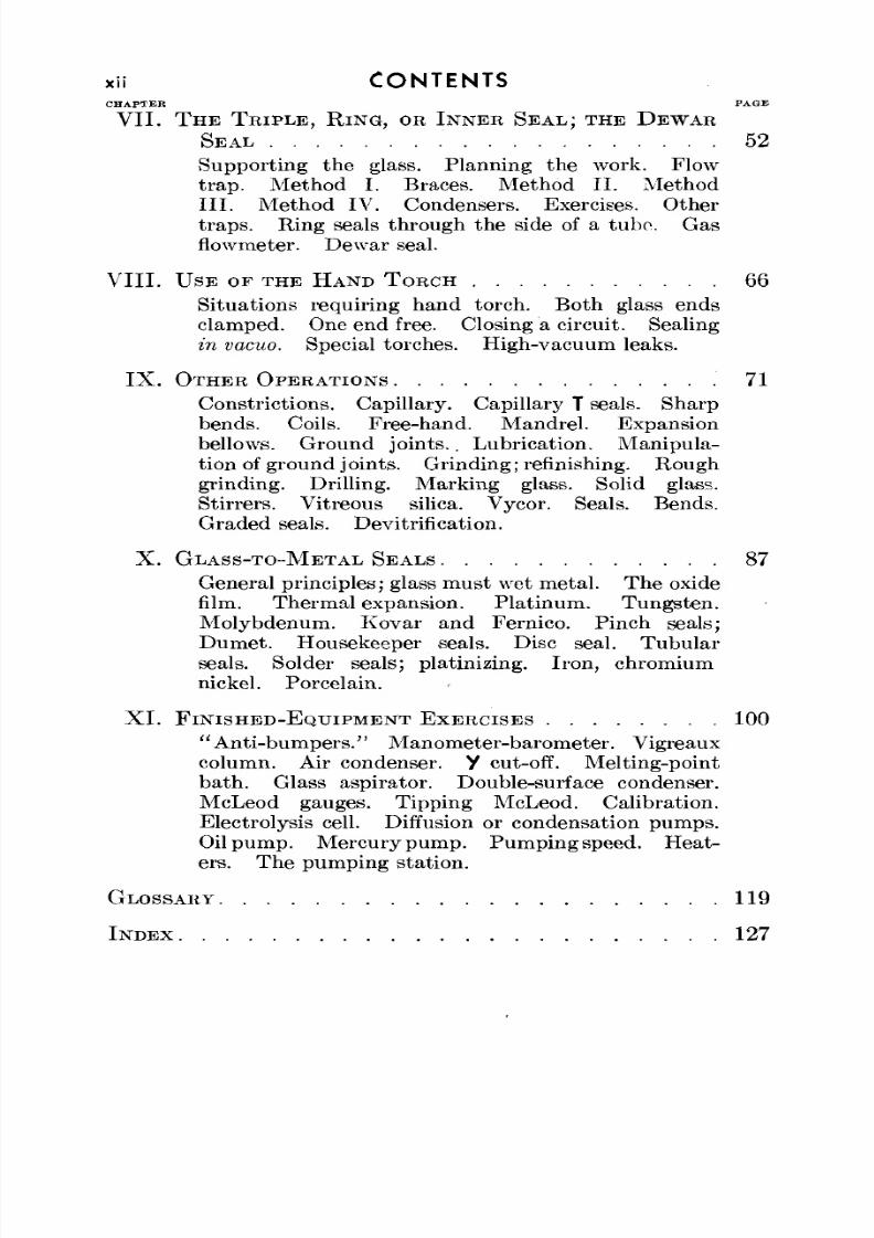
VII . T H E T R I P L E , R I N G , OR I N N E R S E A L ; T H E D E W A R
S E A L 52
Supporting the glass. Planning the work. Flowt rap. M ethod I. Braces. Method II . M ethodI I I . M ethod IV. Condensers. Exercises. Othertraps. Ring seals through th e side of a tubo. Gasflowmeter. Dewar seal.
V I I I . U S E O F T H E H A N D T O R C H 66
Situations requiring hand torch. Both glass endsclamped. One end free. Closing a circu it. Sealingin vacuo. Special torches. High-vacuum leaks.
I X . O T H E R O P E R A T I O N S 71
Constrictions. Cap illary. Capillary T seals. Sharpbends. Coils. Free-hand. Mandrel. Expansionbellows. Ground joints .. Lubrication. Manipula-tion of ground j oints. Grinding; refinishing. Roughgrinding. Drilling. Marking glass. Solid glass.Stirrers. Vitreous silica. Vycor. Seals. Bends.Graded seals. Dev itrification.
X . G L A S S - T O - M E T A L S E A L S 87
General principles; glass must wet metal. The oxidefilm. Therm al expansion. Platinu m. Tungsten.Molybdenum. Kovar and Fernico. Pinch seals;Dum et. Housekeeper seals. Disc seal. Tubula rseals. Solder seals; platinizing. Iron, chromiumnickel. Porcelain.
X I . F I N I S H E D - E Q U I P M E N T E X E R C I S E S 100
"Anti-bumpers." Manometer-barometer. Vigreauxcolumn. Air condenser, y cut-off. Melting-pointba th . Glass aspirator. Double-surface condenser.McLeod gauges. Tipping McLeod. Calibration.Electrolysis cell. Diffusion or condensation pum ps.Oil pum p. M ercury pum p. Pum ping speed. Heat-ers. The pumping station.
GLOSSARY 119
I N D E X 127
8/3/2019 Techniques of Glass Manipulation - Heldman
http://slidepdf.com/reader/full/techniques-of-glass-manipulation-heldman 13/144
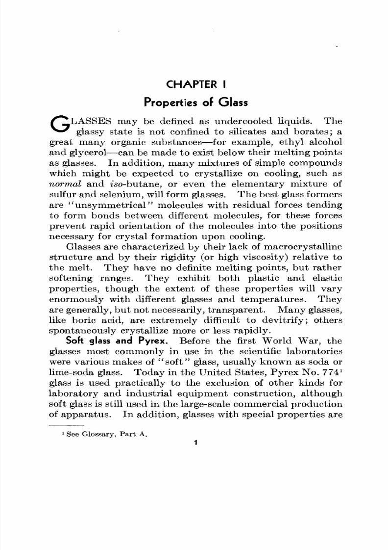
CHAPTER I
Properties of Glass
m ay be defined as undercooled liquids. Theglassy state is not confined to silicates and borates; a
great many organic substances—for example, ethyl alcoholand glycerol—can be made to exist below their melting points
as glasses. In addition , m any mixtures of simple compoundswhich might be expected to crystallize on cooling, such asnormal and iso-butane, or even the elementary mixture ofsulfur and selenium, will form glasses. The best glass formersare "unsymmetrical" molecules with residual forces tendingto form bonds between different molecules, for these forcesprevent rapid orientation of the molecules into the positionsnecessary for crystal formation upon cooling.
Glasses are characterized by their lack of macrocrystallinestructure and by their rigidity (or high viscosity) relative tothe melt. They have no definite me lting po ints, but rathersoftening ranges. Th ey exhibit bo th plastic and elasticproperties, though the extent of these properties will varyenormously w ith different glasses and tem peratu res . Theyare generally, but not necessarily, trans pa rent. M any glasses,
like boric acid, are extremely difficult to devitrify; othersspontaneously crystallize more or less rapidly.
Soft glass and Pyrcx. Before the first W orld W ar, theglasses most commonly in use in the scientific laboratorieswere various makes of " so ft " glass, usually known as soda orlime-soda glass. To day in the United States, Pyrex No. 774
1
glass is used practically to the exclusion of other kinds forlaboratory and industrial equipment construction, althoughsoft glass is still used in the large-scale commercial productionof ap pa ra tus . In add ition, glasses w ith special properties are
1See Glossary, Part A.
8/3/2019 Techniques of Glass Manipulation - Heldman
http://slidepdf.com/reader/full/techniques-of-glass-manipulation-heldman 14/144
2 PROPERTIES OF GL AS S
available, as is also vitreous silica (commonly but incorrectlycalled quartz).
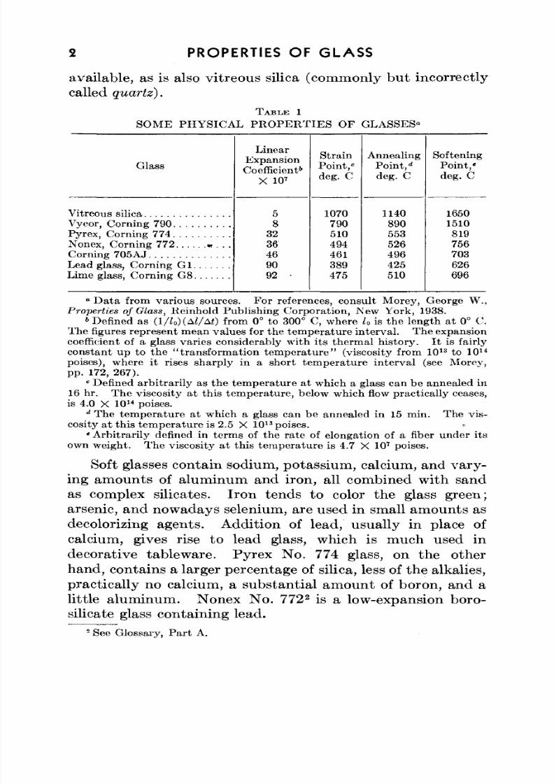
TABLE 1
S O M E P H Y S I C A L P R O P E R T I E S O F
Glass
Vitreous silica
Vycor, Corning 790Pyrex, Corning 774Nonex, Co rning 772 « . . .Corning 705AJLead glass, Corning GlLime glass, Corning G8
LinearExpansionCoefficient
5
X 10'
5
8323646909 2 •
StrainPoint ,"deg. C
1070
790510494461389475
GLASSES-
AnnealingPoint,
1*
deg. C
1140
890553526496425510
SofteningPoint , 'deg. C
1650
1510819756703626696
° D at a from va riou s sources. Fo r references, consu lt Morey , George W .,Properties of Glass, Reinhold Publishing Corporation, New York, 1938.
6Defined as (l/Zo)(AZ/A<) from 0° to 300° C, where U is the length at 0° C.
Th e figures represent mean values for the tem per atur e interv al. Th e expansion
coefficient of a glass varies considerably w ith its the rm al histo ry. I t is fairlyconstant up to the "transformation temperature" (viscosity from 1013 to 1014
poises), where it rises sharply in a short temperature interval (see Morev,pp . 172, 267).
cDefined arbitrarily as the temperature at which a glass can be annealed in
16 hr. Th e viscosity at this tem pe ratu re, below wh ich flow practica lly ceases,is 4.0 X 10
14poises.
dTh e tem pe ratu re at which a glass can be annealed in 15 min. Th e vis-
cosity at this temp eratu re is 2.5 X 10¹³
poises.* A rbitrarily defined in term s of the ra te of elongation of a fiber und er its
own weight. Th e viscosity at this tem pera ture is 4.7 X 10⁷
poises.
Soft glasses contain sodium, potassium, calcium, and vary-ing amounts of aluminum and iron, all combined with sandas complex silicates. Iro n tends to color th e glass green;arsenic, and nowadays selenium, are used in small amounts asdecolorizing agents. Addition of lead, usually in place ofcalcium, gives rise to lead glass, which is much used indecorative tablew are. Pyrex No . 774 glass, on the other
hand, contains a larger percentage of silica, less of the alkalies,practically no calcium, a substantial amount of boron, and alittle aluminum. Nonex No. 772
2is a low-expansion boro-
silicate glass containing lead.2
See Glossary, Part A.
8/3/2019 Techniques of Glass Manipulation - Heldman
http://slidepdf.com/reader/full/techniques-of-glass-manipulation-heldman 15/144
PROPERTIES OF GLASS 3
Soft glass, Pyrex, and all other inorganic glasses are poorheat conductors and, except near their softening ranges, good
electrical insu lators . This first fact makesit
possibleto use
an extension of glass as a working handle without protectingthe hands.
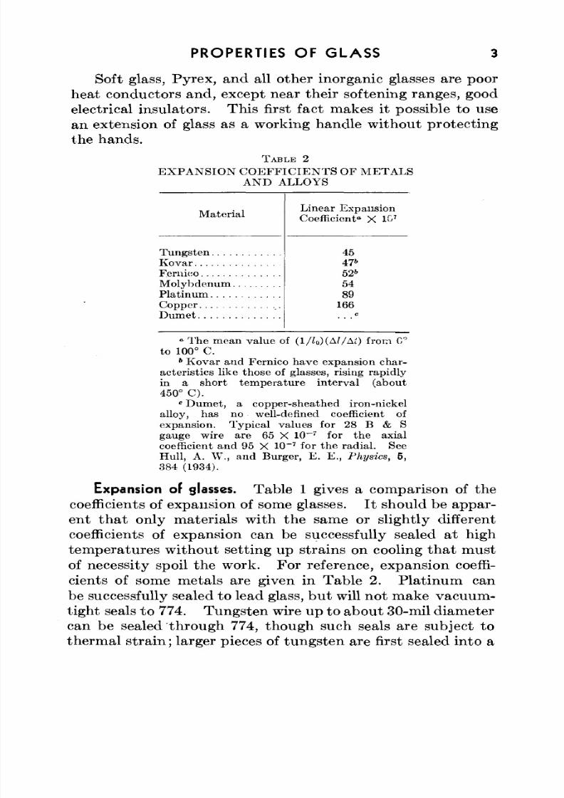
TABLE 2
EXPANSION COEFFICIENTS OF METALS
AND ALLOYS
Material
Tungsten
Kovar
Fernieo
Molybdenum
Platinum
Copper
Dumet
Linear Expansion
Coefficient" X 107
45476
526
54
89
166
» The mean value of (l/lo)(Al/Ai) from C
to 100° C.6
Kovar and Fernieo have expansion char-
acteristics like those of glasses, rising rapidly
in a short temperature interval (about
450° C).
" Dumet, a copper-sheathed iron-nickel
alloy, has no well-defined coefficient of
expansion. Typical values for 28 B & S
gauge wire are 65 X 10~r
for the axial
coefficient and 95 X 10~7
for the radial. See
Hull, A. W., and Burger, E. E., Physics, 6,
384 (1934).
Expansion of glasses. Table 1 gives a comparison of the
coefficients of expansion of some glasses. It should be appar-ent that only materials with the same or slightly differentcoefficients of expansion can be successfully sealed at hightemperatures without setting up strains on cooling that mustof necessity spoil the work. For reference, expansion coeffi-
cients of some metals are given in Table 2. Platinum canbe successfully sealed to lead glass, but will not make vacuum-tight seals to 774. Tungsten wire up toabout 30-mil diametercan be sealed through 774, though such seals are subject to
thermal strain; larger pieces of tungsten are first sealed into a
8/3/2019 Techniques of Glass Manipulation - Heldman
http://slidepdf.com/reader/full/techniques-of-glass-manipulation-heldman 16/144
4 PROPERTIES OF GLAS S
Nonex No. 772 sleeve, which may in turn be welded success-fully to 774. Soft glass-to-Pyrex No. 774 seals always shatterupon cooling. How ever, by the use of special techniques,many materials of very different expansion coefficients maybe successfully sealed. Some of these techniques are tre atedin Chapter X.
Thermal behavior. Silica glass may be heated white hotand then immediately plunged into cold water without crack-ing, for its contraction on cooling is so small that the cohesivestrength of the material is great enough to keep the relatively
small strains introd uced from startin g a crack. On the otherhand, soft glass heated to a few hundred degrees centigradewill certainly shatter when placed in cold water, or may crackif exposed to a sudden draft, for here the large strains intro-duced upon rapid heating or cooling overcome the cohesivestreng th of the glass. Pyrex N o. 774 lies between soft glassand fused silica in this respect. Tu bing up to 15 mm canusually be exposed directly to a gas-oxygen flame without
cracking.Since glass is a poor heat conductor, it is possible to set up
large temperature differentials between the outer "skin" andthe body of a piece of glass when heating is first started.This temperature difference sets up strains which lead tocracks. Th e same may also be said of cooling. Here the"skin" cools more quickly than the body.
If a piece of glass is heated at one spot only, withoutrota tion in the flame, similar strains will appear. Althoughspot heating is definitely necessary for many glass-workingoperations, it is always a good idea first to heat the wholesurrounding area slowly and evenly, starting with a softyellow flame and continuing with a large brush flame, to thepoint at which the glass just begins to vaporize sodium—thatis , to im pa rt the typ ical yellow color to the flame. This pre-
caution need not be observed with Pyrex No. 774 glass up toabou t 15 mm on simple m anipulations such as m aking T seals.
The proper way to heat a piece of glass evenly is to rotateit uniformly while it is in the flame. After it has beenremoved from the flame, it must still be rotated, assuming
8/3/2019 Techniques of Glass Manipulation - Heldman
http://slidepdf.com/reader/full/techniques-of-glass-manipulation-heldman 17/144
PROPERTIES OF GL AS S 5
axially symmetrical work is desired. Two factors enter inhere-: Heat conduction in air is upwards, so that the under
side of the glass is cooled and hence solidified while the topis still plastic; and glass undergoes gravitational flow, thustending to add to the effect of the blow on the bottom sideand to sub trac t from it on the to p. In other words, hot glasssags. This fact makes it extremely difficult to blow neathorizontal seals with a hand torch.
Annealing. A large or complicated piece of apparatusmay be assumed to be strained after it is blown. Sometimes,
if complicated but small, it may be set aside to cool withoutfurther ado or mishap; but reheating will practically alwayscrack it. Th e proper procedure is to anneal the glass.Ideally, glass is annealed in a thermostatically controlledoven or a lehr. In these devices, the still-hot glass is placedin a chamber heated to a temperature at which the glass isrigid enough to keep its over-all shape but plastic enough toflow so as to relieve interna l strains. I t is then cooled slowly
and evenly to room tem peratu re. Ev en though strains mustdevelop on further cooling after the glass "s e ts , " these strainsare never great enough to rup ture the glass. Table 1 liststhe characteristic temperatures for various glasses used in thelaboratory.
Most laboratories do not have an annealing oven, and hotglass must be cooled slowly by judicious use of flames. After
a piece of work has been blown, it is heated uniformly over awide area surrounding the work to a temperature just belowthe softening point but above the strain poin t. For 774 thiscorresponds to incipient red hea t. Nex t, the work is rotateduniformly in a large, slightly yellowish brush flame. Fina lly,a very yellow, sooty flame is used to cover the work evenlywith a deposit of lampblack. Th e work is then set aside,preferably with no hot surface in contact with anything, in a
place free from drafts. For complicated soft glass, wrappingthe worked parts in cotton is often recommended, but thisprecaution should never be necessary for 774 unless the roomis drafty.
Presumably the lampblack coat serves to give a surface
8/3/2019 Techniques of Glass Manipulation - Heldman
http://slidepdf.com/reader/full/techniques-of-glass-manipulation-heldman 18/144
6 PROPERTIES OF GL AS S
which tends to cool more slowly and evenly than a clear glassface, though the quantitative extent to which this is true isprobably small. The real reason for specifying the soot layeris to insure even exposure of the worked glass to a soft, coolingflame.
Some glass blowers recommend hea ting of th in glass in anycomplicated assembly to a little higher temperature thanadjacent thicker glass, for the reason that the thin glass coolsmore quickly, and hence would then approach annealing con-ditions at abo ut the same time as the thicker pa rts . Such a
procedure is practica lly impossible, in m any cases, and fur-thermore i t is dangerous because the thin glass is easily heatedabove its softening point, so that the finished work may bespoiled and m ay require further tre atm en t. At best, such aprocedure m ay help a little in relieving strains , but it does no tseem reliable enough to justify its use.
Devitrification. Every glass has a characteristic temper-ature range in which crystals (or at least submicroscopic
oriented aggregates) can form and will not redissolve with-out very intense heating. In this tem perature range glasstends to devitrify. How ever, for Pyrex-b rand glasses, therate of devitrification is slow and the temperature rangesmall, so th at translucent worked Pyrex is seldom encountered.A translucent or opaque appearance in 774 may usually becured by heating the glass more strongly and by blowinggently and keeping the two parts of the hot joint absolutelystationary with respect to one another until they cool belowred heat.
None of the chemical methods for treating devitrificationare infallible. Sprinkling the hot glass with various saltcrystals is often harmful. Rinsing with aqueous hydro-fluoric acid som etimes helps if only surface devitrification isinvolved. Indeed , devitrification is seldom encou ntered with
774, and even when present does not seem to impair thestrength of the w ork. Cleanliness is the most im po rtan tfactor in com bating cloudiness in worked glass. I t should bea general rule not to heat dusty, greasy, or otherwise dirtyglass.
8/3/2019 Techniques of Glass Manipulation - Heldman
http://slidepdf.com/reader/full/techniques-of-glass-manipulation-heldman 19/144
CHAPTER II
Flames and Torches
Flame characteristics. Flames are flowing gases th at havebecome hot enough to luminesce, usually chemically—that is,in which the heat of a chemical reaction has brought the gasesto a tem peratu re at which they give off light. Th e reaction is
almost always combustion, the combustible gas (natural gas,producer gas, butane, acetylene, or even hydrogen) beingcombined with a supply of oxygen from air or the pure gas,and continuously ignited at a given po int or area. A '' reduc-in g " flame is one in which the com bustible gas stream exceedsthe equivalent oxygen flow necessary to produce completecombustion of the gas; hence the ignited gas still has hot,unreacted reducing agents in it. Such flames are almost
always yellow and are often smoky and sooty with lamp-black. Oxidizing flames contain an excess of oxygen; they areusually blue or, in strong daylight, practically colorless. Theyare necessarily used in working lead glass and Nonex N o. 772.
If the velocity of gas issuing from a nozzle exceeds thebackward speed of the flame, then the flame will propagateitself aw ay from th e nozzle. Such flames are usually unstable
and blow ou t. If, on the other han d, the speed of propag ationof the flame is greater, it will "ba ck fire "— tha t is, the flamewill enter the issuing nozzle to the point of mixture of thegases. In general, with stable flames, a steady flow state willbe reached in which the flame head will be stationary andclose to (but not touching) the nozzle.
By proper engineering of the torc h, flames may be made tobe " b ru s h " type or "focusing." These aspects will be con-
sidered later .Heating equipment. The minimum amount of heating
equipment necessary to do Pyrex No. 774 work with tubingup to one inch in diameter is a hand torch, connecting tubing,
7
8/3/2019 Techniques of Glass Manipulation - Heldman
http://slidepdf.com/reader/full/techniques-of-glass-manipulation-heldman 20/144
8 FLAME S A N D TORCHES
and a controllable source cf gas and oxygen. Th e latte r twoare a sine qua non, to which may be added an air supply ifsoft glass is to be worked. Available and useful torches arelarge in number. After some practice, every worker willdevelop preferences for certain torches. Limitations ofeconomy and availability usually determine the amount andtype of heating equipment on a glass-working bench, but it ismost certainly worth while to have at hand more than onetype of burner.
Bunsen burner. The Bunsen burner is the most common
laboratory burn er. For pulling, bending, and fire polishingsmall-bore soft-glass tubing , it is quite satisfactory. Theoxidizing flame is of the focusing type—that is, with a rela-tively cold inner cone surrounded by a hot, fairly well-definedtaperin g area. Such flames are used for heating small areas.W hen a bend is required, a long surface of glass m ust beheated, and a fan tip (fishtail) must be slipped over the burnertip. The resultant flame is still focused but is long and thin.
One im po rtan t use of the Bunsen b urner is as a pilot light.There are times when the blowing out of a blast brush flamewould be disastrous; here a pilot proves its value as well asacting as a permanent "match" for the hand torch.
Meker burner. The Meker burner is in essence a numberof Bunsen burners in juxtaposition. W hen properly adjusted,the oxidizing flame is quite even in temperature distribution.
It may be used for bending soft glass or even small 774 tub-ing. Tw o M ekers side by side can be used successfully tobend 774 up to 10- or 11-mm o.d. The Meker, since itgives a large, even flame, not quite so hot as a gas-oxygenflame, can be used for the initial heating of large glass andalso for annealing, tho ugh other burners may be more suitable.For slow hea ting, th e reducing flame (air inlets par tially shu t)is first applied, and the air supply is gradually increased.
Initial heating. Most professional glass blowers use amammoth multiple-jet or "locomotive" type burner, towhich oxygen can also be fed, for initial heating and anneal-ing. These burners are only a few inches high and may beset in front of another torch to give general, even heating in
8/3/2019 Techniques of Glass Manipulation - Heldman
http://slidepdf.com/reader/full/techniques-of-glass-manipulation-heldman 21/144
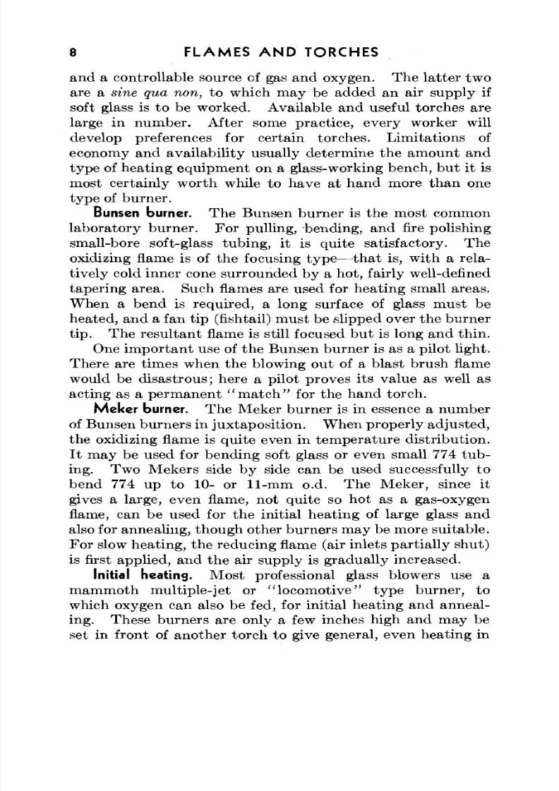
mto Z o—IOTO r I mC
Fg1CmmotyohneqpmenA
h
e
o
h
so
n
h
b
aeaMe
y
b
n
a"o
mo
v
w
hg
a
o
nesa
a
h
w
hg
ne
a
a
ne
o
In
h
so
ae
a"w
e
o
rb
b
n
u
nb
n
ag
u
n
a
sn
e
a
m
pee
co
e
A
h
rg
aeshw
ah
oc
w
h
re
a
e
p
nu
n
co
e
(pcn
oc
aB
b
n
a
aba
am
w
hg
a
o
a
a
tw
aen
v
ps
oe
o
h
e
8/3/2019 Techniques of Glass Manipulation - Heldman
http://slidepdf.com/reader/full/techniques-of-glass-manipulation-heldman 22/144
10 FLAM ES A N D TORCHES
conjunction with a smaller, ho tter flame. W ith oxygen, simi-lar burners can be used for w orking tubin g of over two inches.
Hand torches. Th e simplest torch is a hand torch . Themost common types give focused flames (with oxygen), anda number of alternate tips of different sizes give flames fromtiny pinpo ints up to about a half inch in diam eter. For usewith air (though with 774 air is never used), a multiple-jettip is usually furnished.
Permanent torches or blast lamps. Permanent torches of
the kind most popular on glass-working benches ten years ago
have a sliding outer sleeve and two or three alternate tips.They are fitted with gas and oxygen taps and often with athird valve for air.
Use of the torch. The variables that determine the typeof flame are the sleeve position and the gas-air-oxygen ratio;the size is largely determined by the tip and gas-flow rate.The use of air leads to a noisy brush flame. W ith 774 airis employed only for preheating and annealing and, rarely,
for giving stab ility to a large brush flame. In prac tice, it isalmost never necessary to use air when working with 774.
In a torch, oxygen (or air) is fed through the inner tubeterm inating in the nozzle. In some han d torches, the gasesare mixed in the barrel, but generally gas is delivered to theannu lar orifice between the inner tube and the sleeve. If thesleeve end is far in front of the nozzle tip , th e re su ltan t flame
is a long, thin, tapering cone with uneven yellow at the jetbase. Tho ugh th e burner is often used this way in thelaboratory, such a technique is not good for the torch, tendingto oxidize and burn the sleeve tip.
The sleeve end should be practically even with or behindthe nozzle tip . If the gas flow is small and the oxygen-gasratio no t too high, a quiet, pointed flame results. W ith moreoxygen, a hissing, pointed flame starting a few millimeters
from the nozzle ensues. Th is is a favorite flame of profes-sionals. I t is changed into a noisy bru sh flame by increasingboth gas and oxygen supply. Now if the oxygen supply on alarge brush flame is carefully lowered, a yellow, reducingbrush flame may be obtained.
8/3/2019 Techniques of Glass Manipulation - Heldman
http://slidepdf.com/reader/full/techniques-of-glass-manipulation-heldman 23/144
FLAMES AND TORCHES n
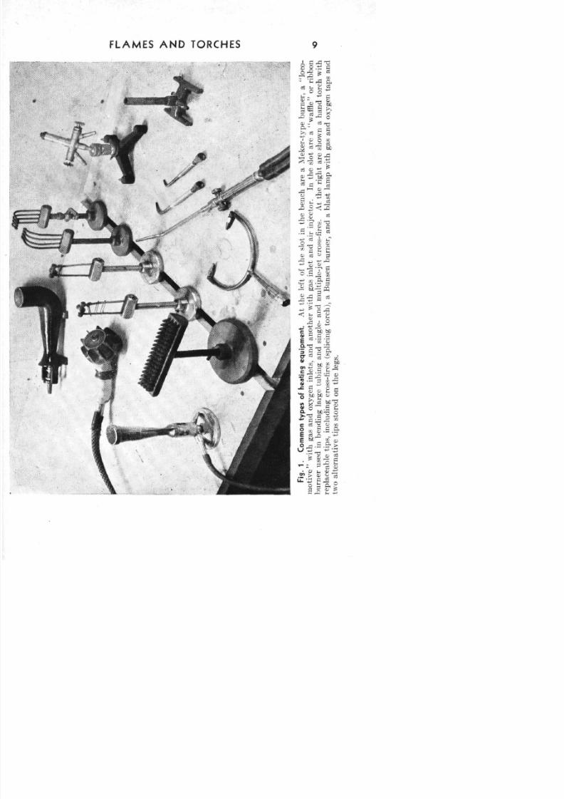
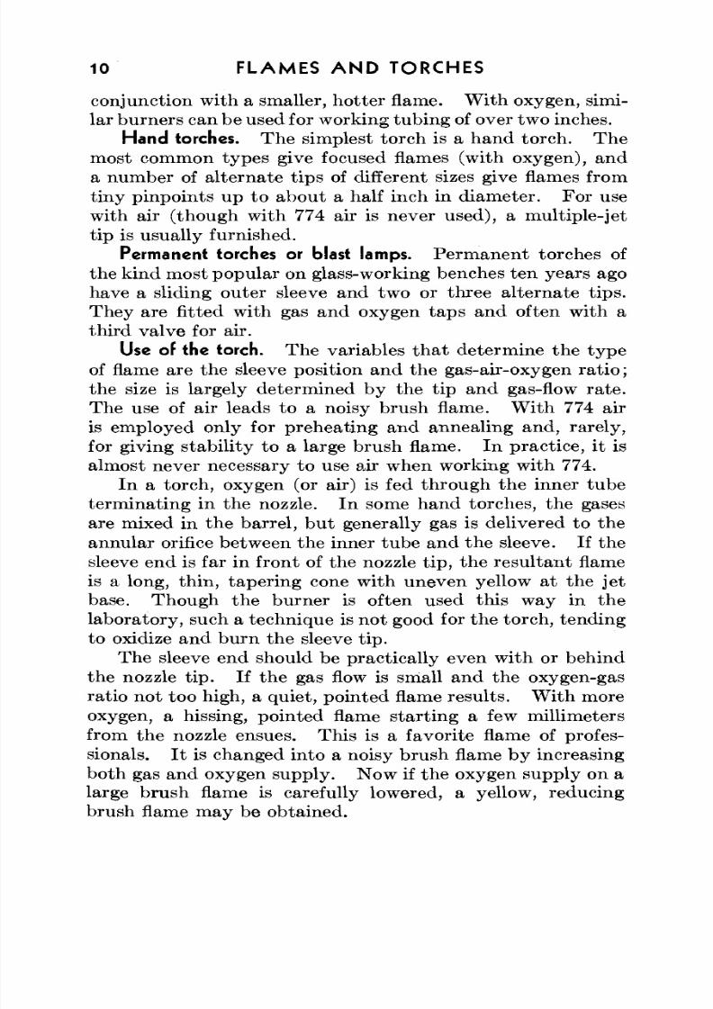
Cross-fires. In thepast two decades, techniques in glassworking have changed enormously. M ultiple fires and cross-
fires have invaded all but the small laboratories, where theyshould become standard equipm ent. Their adv antag es are
Fig. 2. Glass torches. The cross-fires aremounted on a sliding tongue-i scrpw ,.1-in™ adjusted to ~
obvious: They provide more uniform and faster heating.Foot-pedal valve controls are desirable with cross-fires.These can be easily made from gas cocks towhich are a ttache dsteel springs, so th a t the flow of gas and oxygen is almost, butnot quite, shut off when foot pressure is removed from the
8/3/2019 Techniques of Glass Manipulation - Heldman
http://slidepdf.com/reader/full/techniques-of-glass-manipulation-heldman 24/144
12 FLAM ES A N D TORCHES
pedals m oun ted to the cock handles. The idling m ixture isadjusted to act as a convenient pilot light, so that the fires
do not have to be relit every time foot pressure is released.W ith such an arrangem ent, w ork m oun ted on rollers (seeChapter III) does not have to be removed from the flamearea for blowing. The use of foot pedals prac tically makesit necessary to work in a sitting position.
Torches from glass. It is no t necessary to purchase torchesfor most work. Very satisfactory ones m ay be con structedfrom glass, as illustra ted in Fig. 2. Th e outer sleeve is
10-mm o.d. Th e inner nozzle tap ers to about 1.5-mm i.d.at the tip, which terminates 2 mm from the end of the sleeve.Another variation is to make the outer sleeve of brass,braze on a gas-inlet tube, and insert a glass nozzle througha rubb er stopper. W ith glass cross-fires, a necessary precau-tion is to make certain that one fire does not heat the otherglass torch.
Valve control with glass heating equipment is obtainedby use of small brass needle valves or mounted screw clamps.A lubricated stopcock is permissible as a gas valve, butgrease must never be permitted to come in contact withoxygen. Th e pr im ary source of oxygen is usually a high-pressure cylinder. I t should be controlled by a reductionvalve, set at about 8 lb. pressure, gauge. Needle valves areunsatisfactory for control of high pressure.
1
1Heating equipment when properly used is quite safe, but there are a few
precautions to observe. Bulletin No. 95, "Safe Practices in Han dling Com-pressed G ases, " N atio nal Safety Council, 20 N . W acker Driv e, C hicago, 111.,is a valuable guide for the glass worker and may be obtained from the Council.
8/3/2019 Techniques of Glass Manipulation - Heldman
http://slidepdf.com/reader/full/techniques-of-glass-manipulation-heldman 25/144
CHAPTER III
Equipment
blowing is like many other arts in that basic workmay be done satisfactorily with relatively simple equip-
ment, but special tools have been developed for practicallyevery typ e of operation. I t is the purpose of thi s chapter
to describe glass-blowing equipment, starting with the bareessentials and progressing to the many specialized articles.Practically all the equipment described in this chapter maybe obtained from scientific apparatus and supply companiesor can be made in the laboratory shop. Torches and acces-sory equipment have already been discussed (Chapter II).
First aid; goggles. Most important on the list is first-aidequ ipm ent, for everyone who works <with glass must expectat some time to be burned or cu t. D idym ium goggles are agreat help in protecting the eyes, not so much from cuts andburns, which are rare there, but from the intense sodiumcolor of hea ted glass. D idym ium glass (Corning No . 512)contains a mixture of two rare earths, neodymium andpraeseodymium, and the combination shows a remarkableselective light absorption in the region of the sodium D line.
A 2-mm thickness of didymium glass gives practically com-plete absorption of the sodium color encountered at the work-ing tem perature range for Pyrex. W ith these glasses, it isalso possible to correlate the color tem peratu res of Pyrex withits working characteristics.
Stock glass. A good glass stock is a de facto requirementfor glass blowing. Soft glass tubing should either be keptaway from the laboratory proper or at least kept strictly
segregated from Pyrex N o. 774 supply. All small odd piecesleft after working soft glass should be destroyed at once.Every laboratory will require its own general stock list of774. Two-mm cane for use as welding rod is a useful item
13
8/3/2019 Techniques of Glass Manipulation - Heldman
http://slidepdf.com/reader/full/techniques-of-glass-manipulation-heldman 26/144
14 EQUIPMENT
not often encountered, though welding rod may be drawndown from larger cane. Glass tub ing and cane should bestored horizontally, if possible, on a solid bottom, since evenat room tem peratu re they undergo a slow plastic flow. Th isfact does not become important unless long pieces of tubingor rod are used. Th e storage should be kep t as free from dustas is feasible. All special glasses should be kept separatelyand labeled. Calipers or their equivalent are indispensablewhere glass is used.
Distinguishing between glasses. A digression into th e ways
of distinguishing between soft glass and Pyrex glass wouldappear 'to be proper here, for it is one of the problems relatedto glass storage. The simplest way is to com pare the flamebehavior of the piece in question with authentic soft glassand Pyrex N o. 774 of the same size. Soft glass almostalways cracks upon rapid heating (though this is a costlytype of trial), becomes workable at a lower temperature,stays workable longer, and usually shows a slight orange
luminescence somew hat below color tem pe ratu res . A littlepractice makes it easy to distinguish the two when use of theflame is perm issible. The practice of looking down the axisof a tube to judge its character from the color of the walls,soft glass being green in contradistinction to the light yellowof 774, is not recommended, for the color of glasses is veryremarkably changed by small amounts of metals such asiron and arsenic.
1
A unique and foolproof m ethod for determining th e ty peof a suspect glass from only a tiny fragment is as follows:The end of a piece of authentic Pyrex No. 774 cane is heatedand flattened; on the flattened end is placed the fragment inquestion. Th e spot is reheated strongly w ithout rotation,flattened again, once more heated, and then quickly pulledout to a long th in ribbon . If the suspect glass is Pyrex
1Pyrex chem ical resistant glass No. 774 m ade before 1935 contained a sm all
amount of arsenic oxide, which imparted a straw-yellow color to tubing vieweddown the wall end. W ith the remo val of arsenic oxide from th e formula, tho ughthe physical properties and heating characteristics are practically identicalwith the original glass, 774 no longer shows th e distinctive end color. " O ld "glass may still be tentatively identified by color.
8/3/2019 Techniques of Glass Manipulation - Heldman
http://slidepdf.com/reader/full/techniques-of-glass-manipulation-heldman 27/144
EQUIPMENT 15
No. 774, the ribbon will show no tendency to curl; if it issoft glass, it will spontaneously form a spira l. Th e technique
may be applied to other glasses w ith very different coefficientsof expansion. If a piece of glass is fused to any know n typeof glass and does not curl, it can be identified as the samegeneral ty pe as the know n glass; if it curls, it is a differenttyp e. Th e principle is the same as th a t in any bi-speciesexpansion element, and it is necessary only to be sure thatthe two pieces of glass have not lost their identity by flowin the melt.
Stoppers. Stoppers for open ends of glass are a necessity.The usual equipment of a laboratory—corks and borers,rubber stoppers, and the like in assorted sizes—are adequate.Many laboratories find it convenient to have a drawer orrack of bored stoppers of all sizes with glass tubing insertedin them for use as a handle or blow end.
Asbestos. Asbestos tape and asbestos paper can also beused to stopper open ends th at are to be heated . These two
items have so many uses in glass blowing that it is advisableto have them at hand if at all possible. Th e thin asbestospaper can always be substituted for the tape.
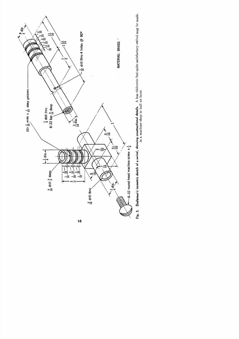
Blow tube, swivel, and mouthpiece. A length of l ight
rubber tubing should always be kept handy for blowing workth at is awkw ard to bring to the mo uth . For rotation ofsuch work, a small swivel, a useful but much neglected
adjunct, is employed. If a rubber tub e alone is used, theworker may clamp his teeth down on the end, shutting offthe work from the air. Th e end of th e rubber should befitted with a mouthpiece, shaped to the worker's taste andstrong enough to withstand the force of clamping of thetee th . An old pipe stem is satisfactory. Unthickened glasstubing is dangerous; professionals often blow bulges in thick-walled capillary tub ing for the purpose. A glass mouthpiece
is of course fire polished.Glass cutters. For cutting or breaking glass, files are the
most generally useful and satisfactory instrum ents. A 6-in.triangular file is suitable; when the edges become dull, theymay be reconditioned to form a very good glass knife by
8/3/2019 Techniques of Glass Manipulation - Heldman
http://slidepdf.com/reader/full/techniques-of-glass-manipulation-heldman 28/144
id
hu
(6
^wide
x 6d
P
go
•gd
hu
63a
^d
63
o
ham
nsewx-
Xdh
u4he
@9
M
A
B
>
Fg 3Da
sm
s
s
mec
s
c
oaswv
s
wn
c
u
o
d
a
s Aess elaborate bq
es
sa
oysw
v
mabma
inamnshnhah
8/3/2019 Techniques of Glass Manipulation - Heldman
http://slidepdf.com/reader/full/techniques-of-glass-manipulation-heldman 29/144
EQUIPMENT 17
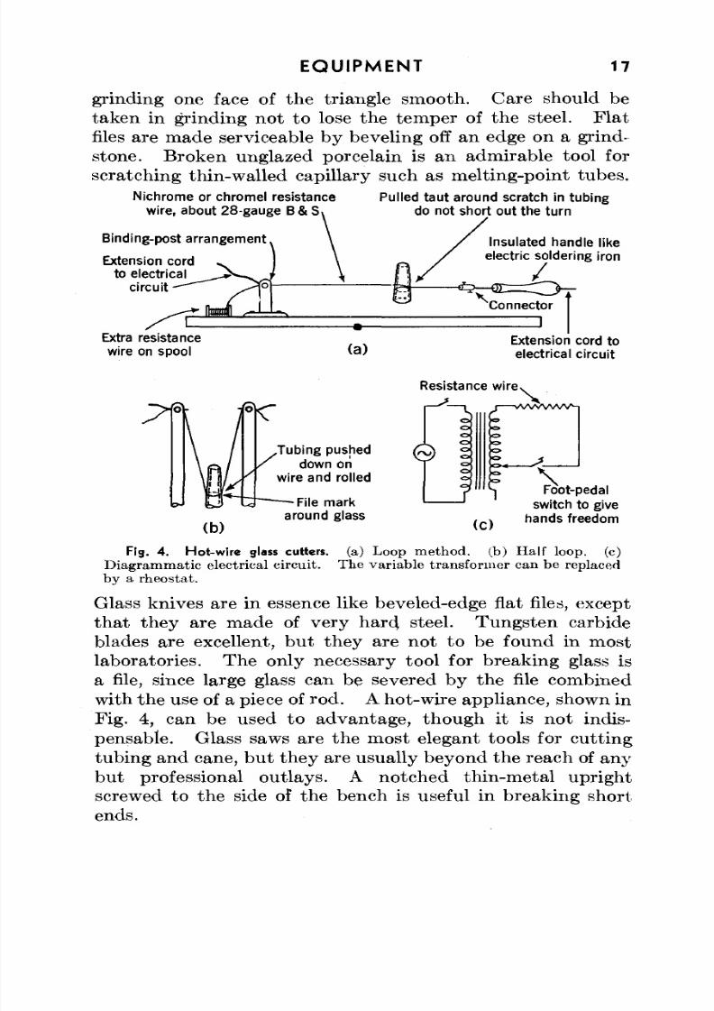
grinding one face of the triangle smooth. Care should be
taken in grinding not to lose the temper of the steel. Flatfiles are made serviceable by beveling off an edge on a grind-stone. Broken unglazed porcelain is an admirable tool for
scratching thin-walled capillary such as melting-point tubes.
Nichrome orchromel resistancewire, about 28-gauge B & S
Binding-post arrangement
Extension cordto electrical
circuit
Extra resistancewire onspool (a)
Pulled taut around scratch in tubingdo not short out the turn
Insulated handle likeelectric soldering iron
Connector
Extension cord to
electrical circuit
Resistance wire
.Tubing pushed/ down on
wire and rolled
File markaround glass
(C )
\Foot-pedal
switch to givehands freedom
F13. 4. Hot-wire glass cutters, (a) Loop method, (b) Half loop, (c)
Diagrammatic electrical circuit. The variable transformer can be replaced
by a rheostat.
Glass knives are in essence like beveled-edge flat files, exceptthat they are made of very hard steel. Tungs ten carbideblades are excellent, but they are not to be found in mostlaboratories. The only necessary tool for breaking glass is
a file, since large glass can be severed by the file combinedwith the use of a piece of rod. Ahot-wire appliance, shown in
Fig. 4, can be used to advantage, though it is not indis-
pensable. Glass saws are the most elegant tools for cuttingtubing and cane, but they areusually beyond the reach of any
but professional outlays. A notched thin-metal uprightscrewed to the side of the bench is useful in breaking shortends.
8/3/2019 Techniques of Glass Manipulation - Heldman
http://slidepdf.com/reader/full/techniques-of-glass-manipulation-heldman 30/144
18 EQUIPMENT
Grinding equipment. W here grinding is to be done, theequipment should include carborundum powder of different
meshes, perhaps 60, 90, 200, 400, and 600 mesh, pumice androuge, and a supply of flat, thick glass pla tes. Power toolsfor grinding glass are available commercially.
Carbons. Pieces of carbon are very handy on the glassblower's bench . Th ey are of two types, the first being longdowels with tapered ends, and the second thin rectangularplates or pad dles. Quarter- and half-inch rods, about 10 in.long, are convenient sizes, while the plates should be in the
neighborhood of y& in. by 3 in. by 5 in., preferably with ahandle attached.
Flaring tools. Flaring tools are not necessary, since mostof their functions can be performed by carbons or a forceps,bu t they are easy to m ake. In their simplest form they aretriangular pieces of m etal to which handles are attached . Anisosceles triangle of ~%- or J^e-in. brass or nickel plate, witha l^-in. base and 2 in. in height, is satisfactory for general use.
Flaring tools w ith multiple blades can also be used. Someworkers merely file corners on the conical end of a thick car-bon rod.
Forceps/ beeswax. A pair of long tweezers finds manyuses, thou gh small ones become too hot to handle. Ten- ortwelve-in. biological specimen forceps are admirably suitedfor glass working. W ith both flaring tools and forceps, to
prevent metal from adhering to the hot glass, it is usuallydesirable to use beeswax. Paraffin is a fair su bs titu te. How-ever, glass that is to be used in high-vacuum apparatusshould not be worked with any wax-coated tools.
Flask holders. Professional glass blowers sometimes em-ploy spring jigs or chucks for holding bulbs. Although theyare very handy, it is almost always possible to circumventtheir use by temporarily sealing a length of tubing on the
base of the flask.Rollers. In a large professional installation, the two
most important items are the lathe or lathes and annealingoven. Neither will be considered here, for the ty pe of workthey handle is certainly bej
rond the range of this book.
8/3/2019 Techniques of Glass Manipulation - Heldman
http://slidepdf.com/reader/full/techniques-of-glass-manipulation-heldman 31/144
EQUIPMENT 19
However, an embryonic form of lathe, consisting of mountedmetal rollers, can be of great help, especially when large orlong glass is encountered. One often sees two rollers on abench, but rarely the four that are required to handle twolarge pieces. V-shap ed grooves cut in half-inch lumber,padded with asbestos and adjustable in height, can be sub-stituted for rollers.
Nowadays stopcocks and ground joints can be obtainedcomm ercially in practica lly any size and style . Other glass-ware such as flasks, and metals like platinum and tungsten
are a necessary par t of a glass blower's equ ipm ent. Diverseitems such as copper-774 tubing seals and graded seals (774-to-silica, and so forth) can be obtained ready made.
The glass blower's bench. The physical outlay of theglass bench is partially a matter of taste if all the re-sources desired are available, but usually the exigencies ofspace and supplies determine the character of the workbench. Th e tab le is preferably situ ated so th at no strong
light shines on the worker. An im po rtan t consideration isthe ventilation— not so much th at t he room be air-conditionedbu t th a t it be draft-free. Ideally, gas, air, and oxygen arepiped to the ben ch; actually, this is seldom so. Gas is usuallypiped (though a tan k of butan e and a reduction valve do verynicely), bu t oxygen is generally stored by the side of the benchin cylinders. For working Pyrex no air supply is needed, butit can be used to advantage, especially on the three-inlet type
of torch.
A few suggestions as to the type of bench are appended,though none fall in the necessary category . The workingspace should be as long as possible. The best covering istransite. Asbestos paper, masonite, and soapstone areusable; wood and pain t should be avoided. At the sides andrear, a notched upright border of wood is useful for resting
hot glass so that it can cool without direct contact with thebench. Any typ e of rest is satisfactory.
Most labora tory benches are a little low for glass blowing.The majority of glass blowers, if they stand, would like abench about 4 ft. high. For working in a sitting position, a
8/3/2019 Techniques of Glass Manipulation - Heldman
http://slidepdf.com/reader/full/techniques-of-glass-manipulation-heldman 32/144
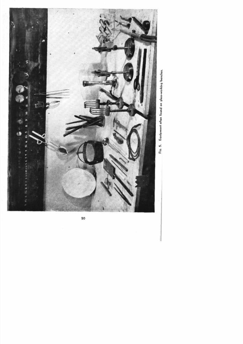
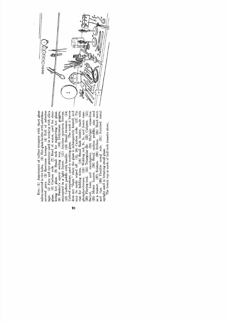
Fg
5
E
pme
oe
o
o
ga
w
kn
b
8/3/2019 Techniques of Glass Manipulation - Heldman
http://slidepdf.com/reader/full/techniques-of-glass-manipulation-heldman 33/144
K
(1
A
o
m
o
ru
so
w
hsh
ga
tu
n
e
n
h
h
e
(2
H
ga
h
d
w
hab
o
c
e
aw
(3
S
m
foc
(4
R
o
ab
o
ta
(5
F
a
e
poe
o
u
nw
kn
w
hsc
ga
(6
C
b
ro
(7
B
w
o
w
e
u
fo
sh
te
n
h
ga
(8
Sm
ra
fo
su
n
h
ga
(9
B
s
sp
es
n
w
(1
Ddm
um
g
e
rem
e
na
g
f
am
(1
A
h
sp
m
foc
(1
C
b
p
ew
hh
e
(1
Sm
w
(1
U
e
so
o
u
nm
kn
ga
T
m
k
e
d
n
"b
n
w
h
ga
ssu
yh
e
a
m
b
e
ywp
o
(1
1
C
b
ro
(1
Pn
vs
fo
h
dn
w
e
(1
Sm
fakh
d
m
wh
p
p
bo
(1
Wedn
ro
2
3
a
5m
c
(2
Fa
n
o
(2
T
a
a
fe
(2
C
p
(2
Swv
h
a
m
h
e
(2
Mu
pe
co
e
(2
Me
b
n
(2
Sm
c
b
p
e
aso
u
a
arem
(2
S
so
(2
R
e
(2
H
oc
a
tp
(3
Feb
e
m
a
rue
(3
N
c
ma
u
g
u
nbe
n
sm
ga
T
b
o
sm
o
h
n
a
esh
8/3/2019 Techniques of Glass Manipulation - Heldman
http://slidepdf.com/reader/full/techniques-of-glass-manipulation-heldman 34/144
22 E Q U I P M E N T
high stool can be obtained . W ith foot-pedal control, a some-what lower bench should be used.
The placing of the torches requires some tho ug ht. A sta-tionary burner should be m ounted securely enough so th at thevalves may be operated without using the other hand tosteady the burner, and the hoses to the torch should be ledfrom behind and undern eath the bench. Oftentimes it pay sto bore holes in the bench so that the hose connections dono t extend over the front. W ith foot-pedal control, the benchist slotted and the tubing brought through the slot.
Two worth-while things to do for a hand torch are todevise a rest so that it can be hung up, leads attached, whennot in use and, if it is used as an in-place torch, to set up amount to clamp it. M any glass blowers always keep aBunsen or Meker burner on the benc h; it is the first flame tobe lit and the last to be extinguished.
A not trivial item is the waste receptacle. I t must bemade of metal, and combustible material should be kept out.
8/3/2019 Techniques of Glass Manipulation - Heldman
http://slidepdf.com/reader/full/techniques-of-glass-manipulation-heldman 35/144
CHAPTER IV
Basic Operations
A SURPRISING number of hot-glass manipulations donot involve blowing, such as cutting, rotation, fire
polishing, flaring, "squaring," bending, "pulling a point,"shrinking, flanging, and bulging. Since in any glass work theglass must be cut, the various methods of severing glass will
be treated first in some detail.Cutting glass. Glass up to 12 or 15 mm in diameter may
be severed easily b y scratching w ith a file and then manuallybreaking at the scratch. Th e file should be sharp enough soth at its "b i t e " is heard. One or two short strokes aresufficient, since the object is not to grind away so much glassthat it is thin at the scratch but rather to start a tiny trans-verse crack th a t grows when torq ue is applied. One methodis to press on one flat of a triang ula r file with a th um b, holdingthe glass steady with the other hand and resting the glassbelow th e scra tch on the forefinger of th e file hand . However,even though this procedure gives very sharp cracks, it is hardon thum bs when the glass sha tters. I t is always advisableto protect oneself either by wrapping the hand in cheeseclothor resting the glass on a flat surface and holding th e file back,
away from the glass.After scratching, the glass is grasped in the h ands, thum bs
adjacent, one on each side of the scratch, and all turnedtoward the chest. As a precaution to insure against too muchleverage, some workers hold the tube very close to the chest,elbows ou t. Also, with fairly large glass, or w ith one endrather short, it is advisable to cover the glass with a rag.
The tube is then pulled with bo th hands opposing. In
the majority of cases, w ithou t any conscious torqu e applied, thetub e will break clean at the scratch. If it does no t break,the pull is released and now is reapplied with the addition of
23
8/3/2019 Techniques of Glass Manipulation - Heldman
http://slidepdf.com/reader/full/techniques-of-glass-manipulation-heldman 36/144
24 BASIC O PE R AT ION S
a slight bending out of bo th elbows. If the glass does notbreak under these conditions, it should be re-scratched; if it
is still recalcitrant, it is probably too large to be broken bythis technique, and another method should be tried. Someglass blowers maintain that wetting the scratch facilitatescracking. Tho ugh th e reason is not understood, this isapparently true and is substantiated by some controlledexperiments.
1
If the scratch is too near one end of the tube to be handledwith both hands, the side of the tube opposite the scratch is
set on a table edge or notched metal upright (the scratchfaces the worker) with the small end sup ported . Th is smallend is then rapped sharply with the file. In this case, a deepfile scratch is advisable.
A glass knife or a diamond cu tter is used in the same way asa file for scratching glass. Bo th make thin ner m arks.
Cutting with hot cane. When the tube is too wide to bebroken by the methods discussed above, it is evenly markedwith a file around its circumference. The tip of a thin pieceof cane is then heated very hot and at once applied any-where on the sc ratch . If th e glass does no t crack, th e caneis reheated, reapplied, and a drop of water immediatelyplaced at the po int of application. Some technicians preferto wet the scratch mark before jamming on the cane tip.
"Leading a crack." For very large glass, when one appli-
cation of the hot rod does not suffice to sever the whole cir-cumference of the tube, the crack is "led" around by placingthe hot cane each time beyond the end of the crack and usingwater if necessary.
The hot-wire method. The hot-wire technique also workswell on large glass. A loop of nichrome or chromel wire,13 mil (28 gauge B & S), is conveniently led throug h insulatedhandles to an adjustable power supply sufficient to heat the
loop to red hea t (see Fig . 4) . Th e wire is then wrappedaround the circular scratch and held taut, the current isapplied for about 30 sec, and water is dripped on the scratch,
1 See Morey, George W., Properties of Glass, p. 323. Reinhold PublishingCorporation, New York, 1938.
8/3/2019 Techniques of Glass Manipulation - Heldman
http://slidepdf.com/reader/full/techniques-of-glass-manipulation-heldman 37/144
BASIC O PE RA TIO N S 25
which should the n crack clean. Care should be tak en not toshort the current at the ends of the loop.
Cutting by blowing out. In addition to these standardmethods of obtaining a given length of glass, one can alwaysheat the glass, seal it, heat it evenly about the circumference,and blow it out. This method is usually neglected in bookson glass work ing; it deserves more a tten tion, since there is farless possibility of a jagged or uneven end resulting after firepolishing.
Rotation. In every case where axially symmetrical work
is desirable, rotation of the glass in the flame is necessary.Glass tub ing is always ro tated while soft, even when it is beingblown. W ith one piece, when only th e tip is hea ted, no diffi-culty arises. Any m ethod of se tting up the work (such aswith rollers) or holding it will do as long as ro tat ion continues.W ith heavy p ieces, it is possible to bear th e work in one handwhile rota ting with the other. Rota tion should no t stopuntil after the glass "sets."
Simultaneous rotation with both hands. If the operat ion
is one in which two parts of cool glass are linked by hot, flow-ing glass, such as in making bends or sealing two tu be s length-wise, it is necessary that both parts be rotated evenly withthe same angular velocity. This is the most im po rtan t singlerule in glass blowing.
Two or three methods may be used to accomplish this
end. If it is assumed tha t the worker is right-handed, themost common is for the glass in the right hand to be heldbetween the thumb and first one or two fingers, with thepalm, thu m b, and fingers pointed up . Sometimes the placeat which the fingers join the palm is used as a bearing. Th eglass can be rotated between the thumb and forefingerabout one-quarter to one-eighth turn depending on its size;then, while the glass rests in the fingers-hand crotch, a new
grip is taken with the thumb and first finger and anothertu rn accomplished. Th e prime reason for holding glass inthe right hand in this manner is to make it convenient tobring it to the mouth for blowing.
The left hand grips the other end of the glass from above,
8/3/2019 Techniques of Glass Manipulation - Heldman
http://slidepdf.com/reader/full/techniques-of-glass-manipulation-heldman 38/144
26 BASIC OP ER AT ION S
with the palm pointed down and the fingers curled. Th eglass is borne by the tips of the last two or three fingers
pressing the tube against the palm; rotation is accomplishedby the thumb and forefinger.One method not generally approved but capable of giving
good results is that of gripping the glass with both hands androtating as described for the left hand above. Actually thismethod gives good results only after the worker trains him-self to flip his right hand under the glass (so that it can bebrought to the mouth for blowing) without altering the axial
alignment or relative rotation rates of the two ends.Other methods of rotation have been suggested but are
not in common use. These methods include holding theends of glass like a pen, and so forth . If a roller is usedfor a bearing, the foregoing methods of rotation still apply;if two rollers support one piece, it may be rolled by the flathand passing over it.
Having decided which method of rotation to employ, abeginner mu st then become proficient in it. There is nosubs titute for practice. Tw o pieces of glass joined by a thinrubber tube form a good practice tool.
While the two ends of glass are rigidly connected, as incool tubing that is to be bent, no problem arises in rotation.When the heated area begins to soften, the tubes mustfinally be aligned axially, without twist, and evenly heated.
Some instructors in glass blowing recommend rotating oneend at a time , the other being held station ary . Such atechnique does work, and well, but the objection is that withsmall work which is heated quickly, not enough rotation isaccomplished to heat the area evenly around the circum-ference. Of course the tem peratu re of the flame can bedecreased, though this may not be desirable with pinpointflames, since par ts adjacent to th e weld would reach a rela-
tively higher temperature in the longer heating interval.One satisfactory method is to rotate both ends about one-fourth turn, recover, and rota te again. W ith practice, theoperations are automatic, the time for complete rotationbeing from 1 to 2 sec.
8/3/2019 Techniques of Glass Manipulation - Heldman
http://slidepdf.com/reader/full/techniques-of-glass-manipulation-heldman 39/144
BASIC OPERATIONS 27
Some workers hold the work palm under in both handsand roll the glass back and forth in the hand between the
thu m b and forefinger. A little tho ug ht will show th a t theperiphery of a piece of glass is not heated uniformly by such aprocedure . However, it is possible to become so proficientwith this technique, by varying the angular speed at differentpa rts of the turn , th at good even heating results. The lefthand is usually finally flipped over the glass for ease in bring-ing the right-hand end to the m outh for blowing. The onlyultimate objection to this technique is that it breaks down
for large tubing, with which a complete rotation cannot beaccomplished by rolling between thumb and forefinger.
Fire polishing. Perhaps the easiest exercise in glass work-ing—and even here rotation is necessary—is fire polishing.A broken end of tubing is brought to the flame and heateduntil the sha rp corners are glazed over. For small glass, nopreheating is necessary. Soft glass can be polished in aBunsen or Meker flame, but only small 774 tubing can be
handled in a Meker. I t is preferable to use a fairly smallsharp flame for the polishing, lest too long an area be heatedand the glass sag in.
Flaring. If the tip of a tube is heated too strongly andtherefore shrinks too far, it can be flared out and thickened(sometimes known as "bordered") by inserting a carbonrod or flaring tool while the glass is still hot, and rolling
the glass arou nd while the tool is held stead y. To prevent thehot glass from sticking to the metal of the flaring arrow, thetool is first warmed and pressed to a cake of beeswax orparaffin (except in cases in which the glass is to be used invacuu m app aratu s) . Sometimes the ends of a pair of forcepscan be inserted into the shrunken orifice, which is thenwidened easily by rota tion . A common error in flaring isheating too much glass. W hen the tube is inserted and the
tubing rotated, the glass twists rather than flares out.Glass ends may also be flared by rota ting them in the flame
while a carbon rod, held at the correct angle, is in the tubing.The carbon should never reach more th an a dull red heat, andshould be long enough so that it is cool at the gripped end.
8/3/2019 Techniques of Glass Manipulation - Heldman
http://slidepdf.com/reader/full/techniques-of-glass-manipulation-heldman 40/144
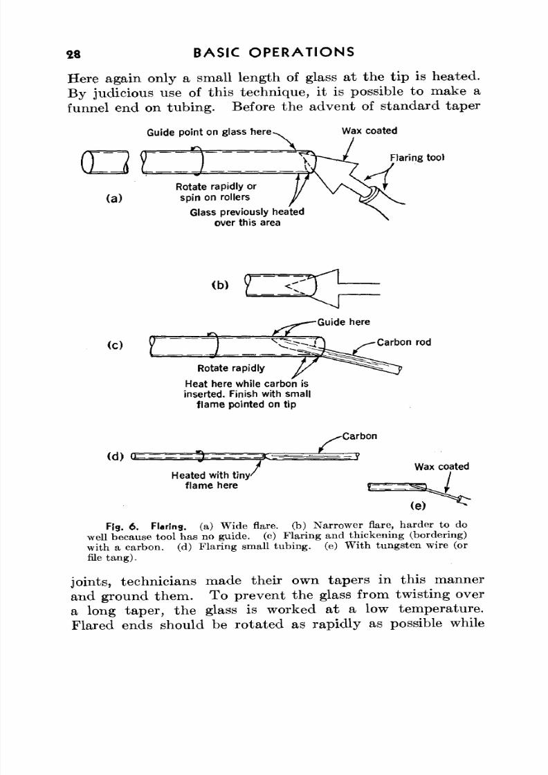
28 BASIC OPERATIONS
Here again only a small length of glass at the tip is heated.By judicious use of this technique, it is possible to make a
funnel end on tubing. Before the advent of standard taperGuide point onglass here
(a)Rotate rapidly or
spin on rollers
Glass previously heated
over this area
Wax coated
Flaring too)
d
(c)
Rotate rapidly
Heat here while carbon is
inserted. Finish with smallf lame pointed on tip
Carbon rod
(d)<E
Heated with t i ny 'flame here
-Carbon
Wax coated
(e)
Fig. 6. Flaring, (a) Wide flare, (b) Narrower flare, harder to do
well because tool has no guide, (c) Flaring and thickening (bordering)
with a carbon, (d) Flaring small tubing, (e) With tungsten wire (or
file tang).
joints, technicians made their own tapers in this mannerand ground them. To prevent the glass from twisting overa long taper, the glass is worked at a low temperature.Flared ends should be rotated as rapidly as possible while
8/3/2019 Techniques of Glass Manipulation - Heldman
http://slidepdf.com/reader/full/techniques-of-glass-manipulation-heldman 41/144
BASIC OP ER AT ION S 29
being worked, preferably being spun on rollers for neat work.Fire polished and flared ends, if made with rotation tech-
nique, need not be annealed unless they are quite large."Squaring off." Often the broken end of a piece of glassis not "sq u a re ." It may be smoothed off by heating thewhole end and then spot heating the high places and pullingoff the excess glass with a forceps or preferably a piece of5- or 7-mm cane. The tip of the cane should be hot enoughso that red-hot glass will stick to it but not hot enough to beplastic. If only one or two low spots are present, the tub ing
end is heated evenly, and then a dot of glass is welded ontothe low spot from a piece of 2-mm cane. If th e weld is thick,it can be heated, squeezed thin with a wax-coated forceps, theexcess drawn off, and finally the whole tip thickened andflared evenly as desired.
It is sometimes possible to chip down an uneven, unpol-ished end of tub ing by using a rus ted wire gauze. The onlyobjection is that small particles of iron oxide are later fusedin to the glass, although these usually offer no trouble. Thereis the slight possibility of a pinhole leak arising from thisaction.
Bending. Small tubing can be bent w ithou t blowing. Itis of prime importance to rotate it evenly and to heat it overa surface at least seven or eight times its diameter to achievea good right-ang le bend withou t blowing. If too small an
area is heated, the inside of the turn will buckle and the out-side will be thin and flattened. Tub ing up to 12-mm o.d.can be ben t to a right angle w ithout blowing. A very wide,fairly cool flame is best. Th e auth or used two Meker burnersside by side to bend 12-mm o.d. Pyrex No. 774 into the loopon the tipping McLeod gauge in the frontispiece withoutblowing. In such a case, a tu rn of only about 30° can beaccomplished at one heating. Rota tion for heating the next
section is difficult, but in the slow-heating Meker flame it ispossible successively to expose different parts of the circum-ference to the flame for a long enough time to get an evenheating . I t is a common error to try to bend glass at toolow a tem peratu re. Pyrex No. 774 tub ing should reach dull
8/3/2019 Techniques of Glass Manipulation - Heldman
http://slidepdf.com/reader/full/techniques-of-glass-manipulation-heldman 42/144
30 BASIC OPERATIONS
? > - * :
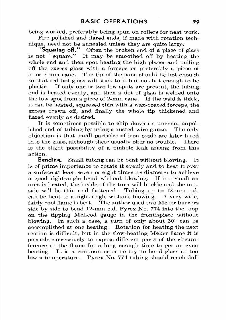
Fig. 7. Types of bends, (a) U-bend , 6-mm tub ing , (b) M andrel-w oun dspiral, 6-mm tub ing . N ot e th at th e tub ing is slightly flattened, (c) Badbend , 10-mm tubin g. Th e outsid e is flattened, and the inside buck ledbecau se too small an area was hea ted, (d) E en d mad e like a T-seal, 12-mmtubing , (e) B end m ade by cuttin g two tube ends at 45° and sealing, 12-mmtubing , (f) Bend m ade by shrinking a small portion of tubin g, bending,and blowing out to shape in one puff, 11-mm tubin g, (g, h) Bend mad ewith one Meker burn er, bending only 10° to 20° at a time, (i) B end m adewith two Meker burne rs side by side, one ben d. N ote tha t the radius is
smaller th an in (g) and (h) and t ha t th e tub ing is slightly flattened.
8/3/2019 Techniques of Glass Manipulation - Heldman
http://slidepdf.com/reader/full/techniques-of-glass-manipulation-heldman 43/144
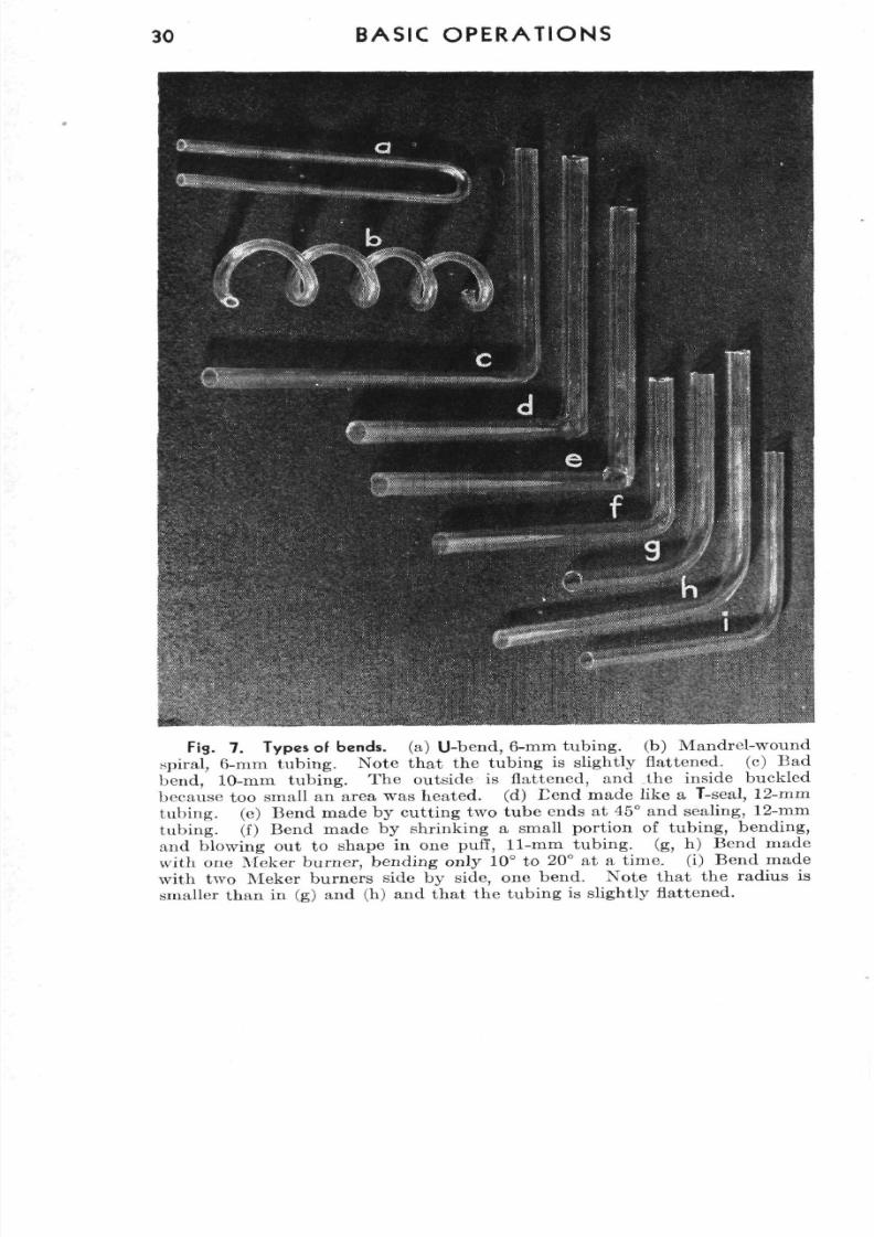
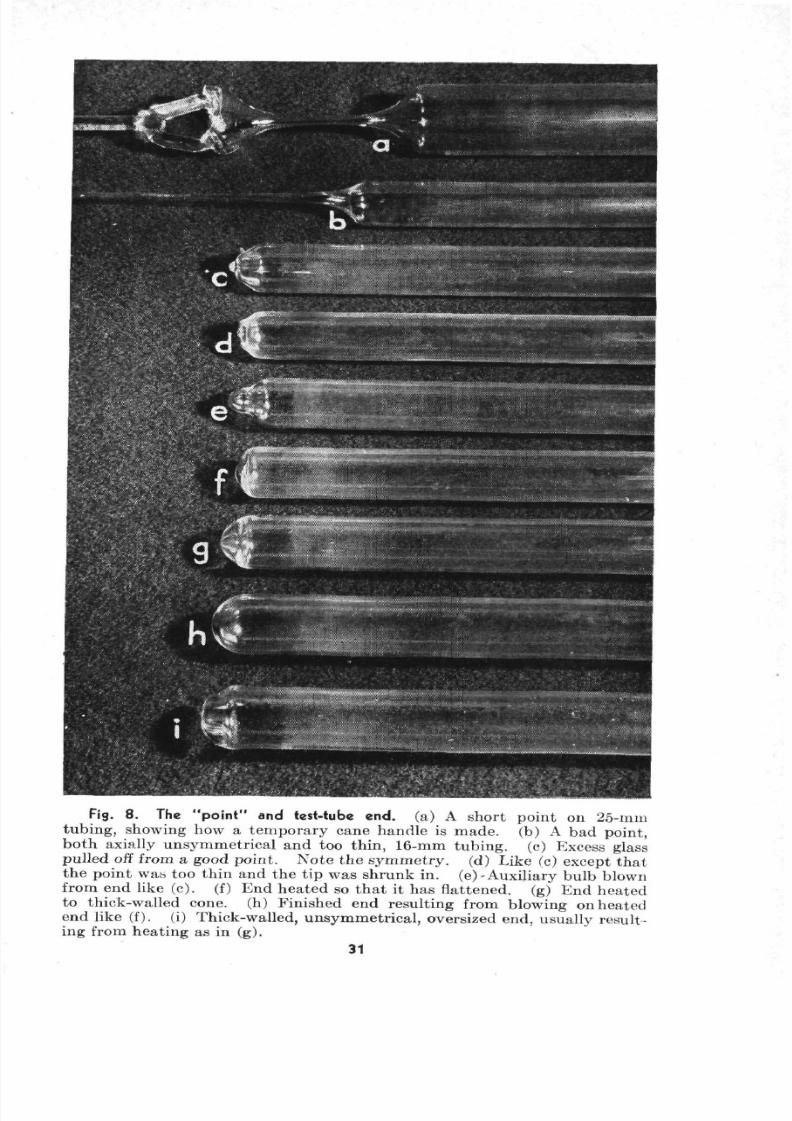
Fig. 8. The "point" and test-tube end. (a) A short point on 25-mmtub ing , showing how a tem po rary cane hand le is ma de, (b) A bad point,bo th axially unsy m m etrical and too thin, 16-mm tubing, (c) Excess glasspulled off from a good point. N ote th e sym m etry , (d) Like (c) except th atthe point was too thin and the tip was shrunk in . (e)-Auxiliary bulb blownfrom end like (c). (f) E nd hea ted so th a t it has flattened, (g) En d heate dto thick-walled cone, (h) Finished en d resulting from blow ing on heatedend like (f). (i) Thick-w alled, un sym m etric al, oversized end, usually result-ing from heating as in (g).
31
8/3/2019 Techniques of Glass Manipulation - Heldman
http://slidepdf.com/reader/full/techniques-of-glass-manipulation-heldman 44/144
32 B A SIC O P E R A T I O N S
red hea t. Also, it is often helpful to pull very slightly whilebending.
Beginners are often required to m ake th e fittings for a washbottle in a Bunsen burner without being supplied with a fan-tip attac hm en t. Th e results are never nea t. W hile a goodglass blower can evenly heat quite a length of tubing in asmall flame by passing the tubing back and forth as well asrotating it, this is certainly too much to expect of a beginner.
Nozzles; "pulling a point." A nozzle is made by heat ing
a long section of tubing' quite hot and "pulling a point"
while still ro tatin g. For a thick-walled, tape red nozzle, theglass over the heated area should be fairly well shrunkbefore being pulled. For a shorter nozzle, a smaller area isheated, bu t just as ho t. Pulling the point before the glassis hot enough results in a thin-walled, fragile nozzle. Herethe effects of uneven rotation show up quite markedly, thenozzle being axially unsym metrical (see Fig. 8).
The drawn-down part is scratched where desired andcracked. For scratching thin capillary glass, broken ends ofunglazed porcelain are be tter th an a file. If the nozzle tipis square, it need not be fire polished.
An alternate method of making a nozzle, now preferred bymany analysts, is to shrink the tip of 7-mm tubing down toany orifice desired.
Flanging. In making a dropper, the nozzle end is made,
and the tubing is cracked off where desired and flared. Someworkers prefer to have a right-angle flange. Such a flangeis made by heating just the tip of a flared end with a pointedflame (the hissing flame does nicely) and pressing a carbonplate against it. The tip may also be flanged by pressing itagainst a clean transite board.
An obvious application of squaring, flaring, and flangingglass tubing is in the common job of repairing broken buret
tops. It should be pointed out that most burets are madeof soft glass, and care should be taken to heat them veryslowly, though a lengthy annealing should not be necessary.A drafty room should be avoided, and the hot part of theglass should not rest on anything while cooling.
8/3/2019 Techniques of Glass Manipulation - Heldman
http://slidepdf.com/reader/full/techniques-of-glass-manipulation-heldman 45/144
BASIC O PE R AT ION S 33
Bomb tubes; temporary handles of cane. In organic reac-
tions, it is often necessary to prepare bomb tube s. Thesetubes should be of thick-walled Pyrex. For sealing of theend after th e reactan ts are introduced , a few hin ts may be ofvalue. Obviously the tube is held almost upright, so th atno reac tants come near hot glass. If a perm anent torch isused, the tip is heated slowly and a handle of cane attachedon the circumference of the tip by heating the cane end andother spot strongly and welding them together. Evenrotation is adm ittedly hard with such a handle. If an evenly
drawn-down end is necessary, a more elaborate symmetricalhandle of cane sealed in two spots to the tip can be made, asshown in Fig. 8.
The whole is then rotated (being held almost perpendicu-lar, of course) in successively hotter flames about an inchbelow the tip until the heated area is quite soft and hasthickened somew hat. I t is then pulled, while rota ting inthe flame, until there is only a few millimeters clearance
between the inner walls. Now the area below the pull isheated, though not to the softening point; and finally a sharpflame applied at the narrow spot, with pulling, suffices toseal the bom b. Th e closure m ust not be reheated to thesoftening point but should be cooled slowly in a smoky flame.If the job is done properly, very little strain should result.The reason for heating below the constriction before the finalseal is to have a volume of hot gas cooling while the finalseal is made so that the greater pressure on the outsidewill tend to push the hot glass together rather than blowingit out.
The hand torch. If the bom b tube is immersed in a coolingba th, the hand torch is used. Th e bom b should be clampedin place. Playing the torch around the periphery of thebomb takes the place of ro tatio n of the tub e. If dry ice
is used as the refrigerant, it should be used in conjunctionwith a noninflammable liquid, such as trichlorethylene orchloroform, or one with a high flash point, such as one of thecellosolves, rath er th an acetone, w hich has a very low flashpoint.
8/3/2019 Techniques of Glass Manipulation - Heldman
http://slidepdf.com/reader/full/techniques-of-glass-manipulation-heldman 46/144
34 BASIC OP ER AT ION S
Melting-point tubes. Good melting-point tubes are oftena bugaboo to the organic chemist. They should have very
thin walls for rapid heat transfer. To achieve this it isnecessary to choose fairly wide diameter tubing to startwith; an ordinary 6-in. test tube, either soft glass or Pyrex;is satisfactory. First the closed end is hea ted and weldedto a cane handle (laboratory stirring rods are almost alwaysmade of soft g lass). Then, with a wide brush flame, a widearea starting about half an inch from the closed end is heateduntil it is soft and beginning to shrink. The glass is removed
from the flame and is at once pulled as far as it will go; it iseven desirable to have a helper walk away with the handleend. Th e thin-walled capillary is sealed by m om entaryexposure to a pinpo int flame in lengths of abou t 10 cm. Th isprocedure keeps the tubes clean and free from dust. W henneeded, the sealed capillaries are scratched with porcelainin the middle and cracked, giving two melting-point tubes.If soft glass is used at a bench at which 774 is worked, all
soft glass ends are destroyed or stored well away from the774 stock.
Bulges. Small glass ends that are to be attached torubber tubing are often bulged or nippled (these bulges areknown to some glass blowers as "M a r ia s" ) . If the glasstubing has not yet been put on an apparatus, it is convenientto bulge in the middle of a longer piece, draw down slightly
on the side to be discarded, cool, scratch with a file on theslight constriction, and then seal on the app ara tus . Thehandle is cracked off and fire polished when convenient.The bulge is made by heating, with rotation, in a pinpointflame and gently pushing the two ends together. Caremust be take n to work the glass at a low tem peratu re. Ontubing over 12-mm o.d., it may be necessary to blow slightly.
Temporary tubing handles. If the glass end is already
sealed into an apparatus, a temporary handle is employed.The technique involved, though fairly delicate, is often a val-uable aid in working with short ends. A convenient lengthof glass of the same size as the glass to be bulged is selected,and both tips are heated jus t above the softening tem perature.
8/3/2019 Techniques of Glass Manipulation - Heldman
http://slidepdf.com/reader/full/techniques-of-glass-manipulation-heldman 47/144
BASIC OPERATIONS 35
For 774 this is a very dull red. The ends are the n placedtogether, pushed slightly, and held until the temporary weldsets. Such a joint has enough stability to withstand theusual torques put on it during subsequent work (though itshould never support a heavy piece) and can be severed quitecleanly by a sharp rap or jar. I t is im po rtan t to get bo th endsof the glass hot enough to stick but not so hot that they flowtogether.
Th e bulge is then p u t on by carefully heating w ith the pin-poin t flame abou t % in. from the tem po rary weld and pushing.
Although it may be impossible to rotate the work properlyfor the bulge, it is always feasible to spot heat about the cir-cumference fairly even ly. Fina lly the handle is tap ped off,and the end is repolished if necessary. If the tem po rary weldis heated to red heat after it is made, the joint may undergosufficient flow to resist subsequent cracking.
Blue glass as a practice aid. Even ro ta t ion and hea t ing
have been stressed throughout this chapter as the prime fac-
tors in glass work. As a visual practice aid, the use of blueglass tub ing is recomm ended. Th is glass undergoes far morestriking visual color changes with temperature, even belowthe softening point, than do colorless glasses, and one caneasily see the relative temperature distribution over all of aheated area.
8/3/2019 Techniques of Glass Manipulation - Heldman
http://slidepdf.com/reader/full/techniques-of-glass-manipulation-heldman 48/144
CHAPTER V
Blowing Involving One Piece of Glass
Sealing a tube end. One of the most common operationsin glass working is sealing off a tube end. From both esthe ticand structural standpoints, it is desirable that the sealed endapproach in appearance a smooth hemispheroidal surface—a test-tube end. W ith free 7- or 8-mm tub ing, such an aim
is easy to achieve. As long as th e sealed end is no t too thick ,is rotated evenly, and is puffed on gently while still beingrota ted , a good appearance results. W ith larger tubing ,more extended manipulation is necessary.
Two cases are to be considered. Th e first is a situatio nin which a long enough piece of tubing is available so that itmay be rotate d with bo th hands while being drawn down. Inthe second, the seal is to be made quite close to the end ofthe tub e. In either event, "pulling a p o in t" is the usualstarting operation.
To do this in the first case, the tube is heated until itbegins to thick en. For the final hea ting, th e diam eter of theflame is one to two times that of the tub e. W hen the glassis hot enough, it is withdrawn from the flame and pulled, bothends being ro tated m eanwhile. Th e constriction of the
pulled point should be concentric with the two ends, and itsextent is judged from the thickness of the main tubing fromwhich the end is to be blown. Large variations in personalpreference are permissible in this operation, some workerspulling a long point and others shrinking a rather narrow,thick collar of glass and pulling very little.
In the second case, the end of the glass is heated strongly,and the glass is "gathered" with cane to form a temporary
handle coaxial w ith the tu be . Th en the tube can be heatedand the point pulled. An alternative method is to heat thedesired area quite hot while rotating, grasp the hot end bypinching it shut with the forceps, and pull away while con-
36
8/3/2019 Techniques of Glass Manipulation - Heldman
http://slidepdf.com/reader/full/techniques-of-glass-manipulation-heldman 49/144
BLOW ING IN V O L V IN G ONE PIECE OF GLASS 37
tinuing to hold the rotating hot glass in the flame and theforceps stead y. This procedure gives a twisted point, which
is not too desirable but does no great harm if the end isproperly worked subsequently. I t is desirable to have thetapered par t of the same thickness as the main tub e. Onlyexperience will tell just how much to thicken the heated wallsand how fast to pull to achieve uniform wall thickness.
After the point is pulled, the excess thin tubing is drawnoff in a small flame, so th a t the tub e end is sealed. This maybe done in the same operation as drawing down the tube. In
any event, a little lum p of glass will remain at the tip . Someof this excess glass can be pulled off after it is heated in a pin-point flame. However, it cannot all be removed this way.If the lum p is not too large, the best way to handle the situa-tion is to heat this lump in a small flame and blow it out intoan auxiliary bulb.
Blowing. In blowing glass, one uses his cheeks and givesa succession of gentle puffs rather than one continuous blow
from the lungs, since control rather than excessive pressureis desired. W ith large pieces of Pyrex . th a t will remainworkable for some time, and with all soft glass, it is necessaryto rotate while blowing to counteract the effects of gravityand uneven cooling of the ho t glass. Th is does no t and can-not mean that a steady rotation is kept up while the glass isin the mouth, although it is possible if a swivel rubber hoseand mouthpiece are used. Rath er the glass is held, puffed on,turned, again blown, and so on until the desired shape isreached or the glass has set. It is often advantageous to blowglass in such a position t hat the ho t portion is axially vertical.W ith a tub e end this means tha t the end points either up ordow n. Specific effects can be achieved by these actions.
After the auxiliary bulb has been blown, the burner ischanged to give a brush flame of about the same diameter as
the tub e, and the whole end is hea ted. If the auxiliary bulbis not too thin, it will shrink uniformly without collapsing,so that the whole end assumes a flat or conical appearance.This end is then blown out to shape.
From this point on, it is difficult to apply any set rules.
8/3/2019 Techniques of Glass Manipulation - Heldman
http://slidepdf.com/reader/full/techniques-of-glass-manipulation-heldman 50/144
38 BLOWING INVOLVING ONE PIECE OF GLASS
Prob ably the most common troubles encountered are irregularthickness of glass, off-center end, and lum py tip . The firstand second can be cured in theory by heating the glass longenough with perfectly even rotation, since the surface tensionof the hot glass tends to make it flow evenly over the roundedend. In practice, however, extended working often makesthe end more off center than ever; the bulgy part is usuallythinner and hence reaches a higher temperature in the flameand blows ou t farth er. I t would be nice if all test- tub e endswere axially aligned, but unfortunately it is often necessary
to heat only one part of the end to doctor the job, and spotheating is never completely satisfactory. Th is heatingshould never be applied to a small spot, but to a substantialsection of the end, say a qu arte r or half of the periphery. Th eglass is then blown, and general heating is not resumed untilthe hotter spot has had a chance to cool a little.
A lumpy tip is always worked out by applying a pinpointor hissing flame to the lump and blowing a small auxiliary
bulb, which is then heated and shrunk along with the restof the end in the brush flame. A small sym metrical lump onthe end actually does no harm.
If the end appears too flat, it may be turned down forblowing. Th is operation tends to make the side walls alittle thinner. W ith a long end, the tip is turn ed up tothicken and shorten it. Here very even rota tion is necessary
to prevent the hot glass from tipping to one side.Very often it will be found that the end has a little largerdiameter than the tube; that is, a small bulb has been blown.If this bulb does no harm it may be left; if necessary, theglass sta rting a t the bulge is draw n down and a new end blown.
Large or long glass can be handled in a roller, using aswivel, a rubbe r tub e, and a mouthpiece. Such work can berotated horizontally while being blown, theoretically the
most ideal situation. In situations in which even rotation isnot possible, the end should be played in a large, fairly coolflame so as to heat the whole area evenly.
Vial end. To make a flat bottom, the test-tube end isreheated in a fairly small flame, with rotation, until the end
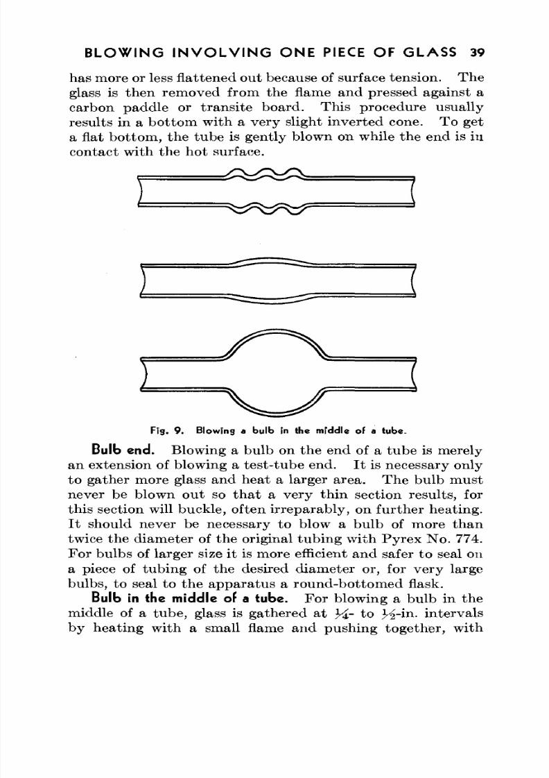
8/3/2019 Techniques of Glass Manipulation - Heldman
http://slidepdf.com/reader/full/techniques-of-glass-manipulation-heldman 51/144
BLOW ING IN V O L V IN G ONE PIECE OF GLASS 39
has more or less flattened out because of surface tension. Theglass is then removed from the flame and pressed against a
carbon padd le or transite board. This procedure usuallyresults in a bo ttom with a very slight inverted cone. To geta flat bottom, the tube is gently blown on while the end is incontact with the hot surface.
i
Fig. 9 . Blowing a bulb in the middle of a tube.
Bulb end. Blowing a bulb on the end of a tube is merelyan extension of blowing a test- tub e end. I t is necessary onlyto gather more glass and heat a larger area. The bu lb mustnever be blown out so that a very thin section results, forthis section will buckle, often irreparably, on further heating.It should never be necessary to blow a bulb of more thantwice the diameter of the original tub ing with Pyrex N o. 774.For bulbs of larger size it is more efficient and safer to seal on
a piece of tubing of the desired diameter or, for very largebulbs, to seal to the apparatus a round-bottomed flask.
Bulb in the middle of a tube. For blowing a bulb in the
middle of a tube, glass is gathered at Y^- to H-in. intervalsby heating with a small flame and pushing together, with
8/3/2019 Techniques of Glass Manipulation - Heldman
http://slidepdf.com/reader/full/techniques-of-glass-manipulation-heldman 52/144
40 BLOWING IN V O LV IN G ONE PIECE OF GLASS
slight blowing if necessary to keep the inner diameter fromdecreasing. Two or three such bulges are sufficient. Th ena large brush flame is applied to the whole area, which is
rotated un til a thick, smooth wall results. The inner diam-eter should not be allowed to shrink, but it is always blownout slightly when necessary. The final hea ting should bedone in a wide but fairly cool flame, since a wide mass of veryfluid glass is almost impossible to handle.
The above may sound like a fairly simple task , but in prac-tice blowing an even bulb in the middle of a tube is one of thehardest free-hand glass manipulations for the average worker,especially with 774. Anyone who can consistently blowesthetically pleasing and mechanically strong bulbs in 15-mmtubing is ready for the m ost extended m anipulations in labora-tory glass working.
Bends. It is almost impossible to make a smooth right-angle bend in tubing over 12-mm o.d. without blowing.Theoretically it can be done with a long enough flame, the
ratio of heated length to tube diameter being the criticalfactor. Prac tically, however, bo th the lack of proper equip-ment and th e difficulty of handling long sections of flowingglass usually make it desirable to finish bends by blowing.For the beginning operation the glass is heated in as wide aflame as it is possible to muster. After some practice, onecan effectively widen the flame by passing the glass back andforth over it as well as ro tatin g it. W hen a wide area is
evenly h ot, it is ben t, w ith slight blowing and pulling, m akingsure that the outside of the bend has not flattened nor theinside buckled. W ith glass up to 12 or 15 mm a large brushflame should make it possible to finish the L with one m anipu-lation. If the bend is no t yet perpendicular, it should bereheated not at the old bend center but to one side. Noweven rotation is impossible but may be approximated with awide, fairly cool flame.
After the bend is made , it should be sm oothed if necessarywith a flame abou t the diameter of the tub e. Usually themajor kinks are on the inside of the ben d. These spots areheated until the kink and the area surrounding it are evenlyred and then puffed gently into shap e. Spot hea ting with a
8/3/2019 Techniques of Glass Manipulation - Heldman
http://slidepdf.com/reader/full/techniques-of-glass-manipulation-heldman 53/144
BLOW ING I N V O LV IN G ONE PIECE OF GLASS 41
pinpoint flame in any operation leads to a "hammered-bron ze" finish, which may be serviceable w ith small glass b utwhich is never so desirable as a smooth surface.
Sharper bends may be made by sealing two separatepieces of glass at the proper angle (Chapter VI), or by amethod often used by accomplished technicians but requiringgood control of hot glass. In th is m ethod , the tube , with oneend stoppered or sealed for blowing, is heated with rotationin a hot, wide flame until a length equal to about two diam-eters is sagging hot and has shrunk to half its initial diam-eter. Th e glass is removed from the flame, ben t, and thenrapidly blown out to initia l size or slightly larger. If the glassis hot enough, the bend will not buckle on the inner side or flat-ten on the outer. These techniques are illustrated in Fig. 7.
Healing cracks. Th e healing of cracks in small tub ing isfairly simple. On small 774 tub ing not involving triple (orring) seals or lumpy glass, the glass is heated, carefully atfirst (a Bunsen or Meker burner makes a good starting po int),
and finally with a hot flame. M an y cracks will heal spon-taneously. I t is the n necessary only to blow lightly to givethe shrunken hot spot its initial shape, or, if it is near an openend, to ream it ou t w ith a carbon rod. If the edges pullaway, leaving a small orifice, welding rod is added until theopening is sealed, and the spot is blown as smooth as possible.The work is cooled slowly. In using welding rod, it isadvisable to add as small an amount as possible; for this
reason 1- or 2-rnm rod is preferable. Rod of this size canalways be drawn down from a larger cane.
The procedure for healing cracks in large tubing, beakers,and the like differs mainly in the initial heating, which shouldbe very slow and diffuse. I t is often adv isable to heat ab ou tan inch away from the ends of the crack first, so that if thecrack grows when intense heat is applied, it will stop at the
hot gla-ss on the edges.Healing a crack in large soft glass is an almost hopelesstask. It might be reiterated th at , though Pyrex equipmentmay seem more expensive, it is actually cheaper when itsgreater mechanical strength, heat-shock resistance, andreparability are compared with those of soft glasses.
8/3/2019 Techniques of Glass Manipulation - Heldman
http://slidepdf.com/reader/full/techniques-of-glass-manipulation-heldman 54/144
CHAPTER V I
End and T Seals
End seals. Both tubes of same diameter. The opera t ions
involved in making tubular end-to-end seals with both glasstubes of the same diameter are in the main shown in Fig. 10.The importance of this fundamental manipulation cannot beoveremphasized; hence, in addition to the photographic
examples, some of the details are explained in the followingdiscussion.
The tube ends should be squared before starting . Anyimperfections in the tube ends will show up as lumps or thinspots in the final join unless it is subjected to prolonged workingin the flame. Some glass blowers prefer to flare and thickenthe ends before starting; this procedure is not necessary withsmall tubing , though with glass over 1 in. in diam eter flaring
may facilitate the initial seal.Personal preference and experience determine the flame
size. After the preheating with a wide, soft flame, a goodworking flame is between radius and diam eter size. Forfinishing the joint smooth, a flame twice as wide and some-what cooler is used.
Rotation method. The two ends are simultaneouslyheated with rotation (the tip of one piece being closed for
blowing) un til the glass at the tips has begun to shrink. Th eends are then removed from the flame, brought together,pressed slightly, and blown rather hard with perhaps a littlepull. It is extremely im po rtan t tha t the ends be broug httogether squarely. Some workers bring the ends toge therat an angle so that only a small part of each touches; thenthe rest is guided into place by decreasing the angle. If th etwo pieces do not seal securely, leaving a hole, it is best toreheat the whole joint with slight pressing.
It is not absolutely necessary that the glass be removedfrom the flame for joining. Indeed, it is possible to continue
42
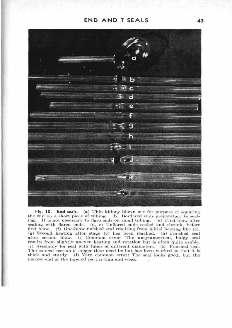
8/3/2019 Techniques of Glass Manipulation - Heldman
http://slidepdf.com/reader/full/techniques-of-glass-manipulation-heldman 55/144
END A N D T SEALS 43
Fig. 10 . End seals, (a) Th in kid ney blown ou t for pu rpo se of squ aringthe end on a sho rt piece of tub ing , (b) B ordered ends pre pa rato ry to seal-ing. It is no t necessary to flare ends on small tub ing , (c) F irst blow aftersealing with flared ends, (d, e) Unflared en ds sealed and shru nk , beforefirst blow, (f) One-blow finished seal resu lting from in itial he ati ng like (e).(g) Second heatin g after stage (c) has been reached , (h) Finished seal
after second blow, (i) Com mon erro r: The unsy mm etrieal, bulgy sealresults from slightly uneven heating and rotation but is often quite usable.(j) Assembly for seal w ith tube s of different di am eter s, (k) Finishe d seal.The conical section is longer than need be but has been worked so that it isthick and stu rd y. (1) Very comm on error: The seal looks good, but th enarrow end of the tapered part is thin and weak.
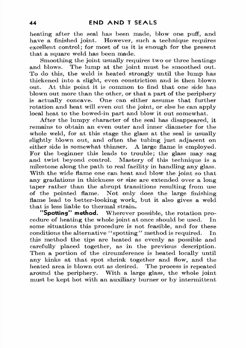
8/3/2019 Techniques of Glass Manipulation - Heldman
http://slidepdf.com/reader/full/techniques-of-glass-manipulation-heldman 56/144
44 END A N D T SEALS
heating after the seal has been made, blow one puff, andhave a finished join t. How ever, such a technique requiresexcellent control; for most of us it is enough for the presentthat a square weld has been made.
Smoothing the joint usually requires two or three heatingsand blows. Th e lump at the joint m ust be smoothed ou t.To do this, the weld is heated strongly until the lump hasthickened into a slight, even constriction and is then blownout. At this po int it is common to find th a t one side hasblown out more than the other, or that a part of the periphery
is actually concave. One can either assume th a t furtherrotation and heat will even out the joint, or else he can applylocal heat to the bowed-in part and blow it out somewhat.
After the lumpy character of the seal has disappeared, itremains to obtain an even outer and inner diameter for thewhole weld, for at this stage the glass at the seal is usuallyslightly blown out, and often the tubing just adjacent oneither side is somewhat thinn er. A large flame is employed.
For the beginner this leads to trouble; the glass may sagand twist beyond con trol. M astery of this technique is amilestone along the path to real facility in handling any glass.W ith the w ide flame one can heat and blow the joint so th atany gradations in thickness or size are extended over a longtaper rather than the abrupt transitions resulting from useof the pointed flame. Not only does the large finishingflame lead to b etter-looking work, but it also gives a weldthat is less liable to thermal strain.
"Spotting" method. W herever possible, the ro tation pro-cedure of hea ting the w hole joint at once should be used. Insome situations this procedure is not feasible, and for theseconditions the alternative " sp o tti n g " method is required. Inthis method the tips are heated as evenly as possible andcarefully placed together, as in the previous description.
Then a portion of the circumference is heated locally untilany kinks at that spot shrink together and flow, and theheated area is blown ou t as desired. The process is repea tedaround the periphery . W ith a large glass, the whole jointmust be kept hot with an auxiliary burner or by intermittent
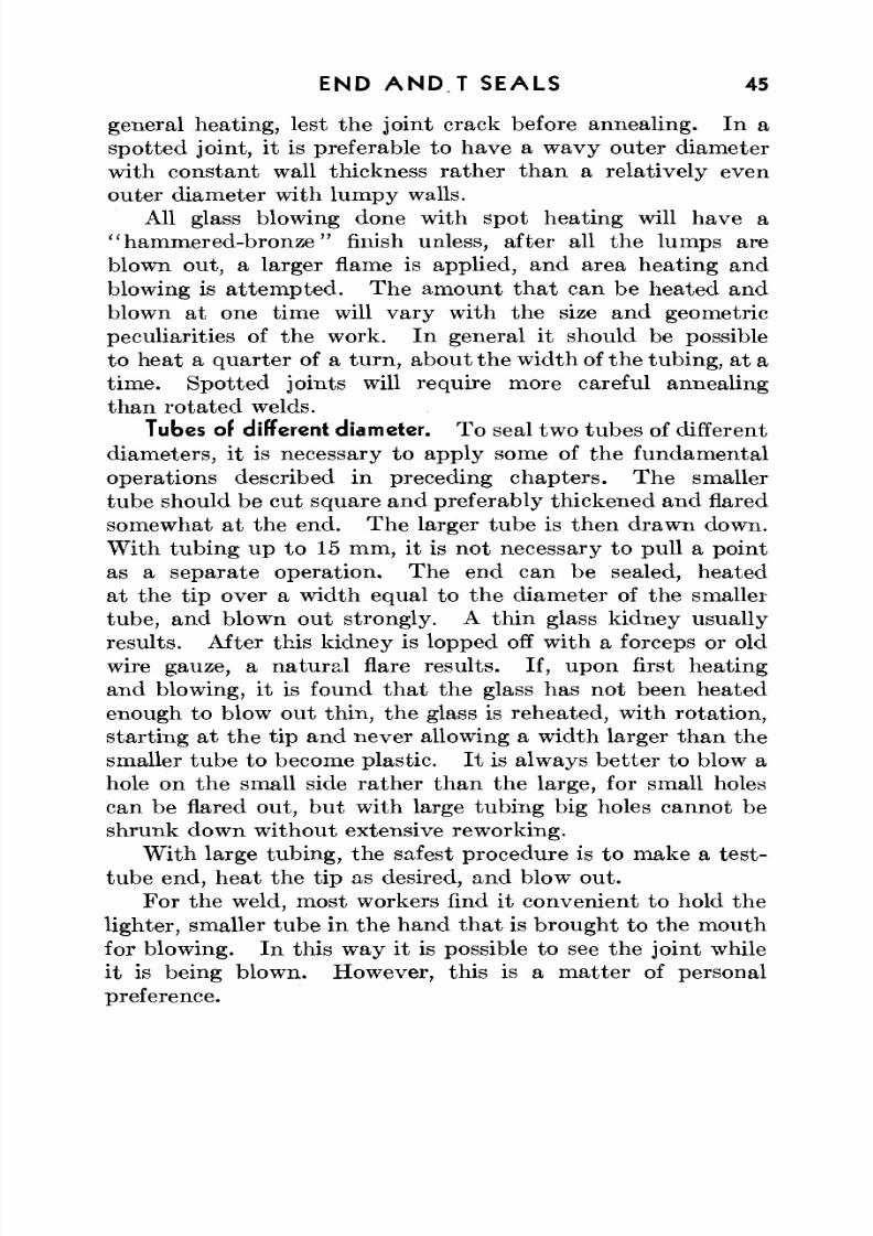
8/3/2019 Techniques of Glass Manipulation - Heldman
http://slidepdf.com/reader/full/techniques-of-glass-manipulation-heldman 57/144
END A N D T SEALS 45
general hea ting, lest the joint crack before annealing. In aspotted joint, it is preferable to have a wavy outer diameter
with constant wall thickness rather than a relatively evenouter diameter with lumpy walls.All glass blowing done with spot heating will have a
" ham m ered-b ronze" finish unless, after all the lumps areblown out, a larger flame is applied, and area heating andblowing is attem pte d. Th e am oun t th a t can be heated andblown at one time will vary with the size and geometricpeculiarities of the work. In general it should be possible
to heat a q uar ter of a tu rn , abou t the w idth of the tubing, at atime . Spotted join ts will require more careful annealingthan rotated welds.
Tubes of different diameter. To seal two tubes of differentdiameters, it is necessary to apply some of the fundamentaloperations described in preceding chap ters. Th e smallertube should be cut square and preferably thickened and flaredsomewhat at the end. The larger tub e is then drawn down.W ith tub ing up to 15 mm , it is not necessary to pull a pointas a sep arate operation. The end can be sealed, heatedat the tip over a width equal to the diameter of the smallertube, and blown out strongly. A thin glass kidney usuallyresu lts. After th is kidney is lopped off w ith a forceps or oldwire gauze, a natu ra l flare results. If, upon first heatingand blowing, it is found that the glass has not been heated
enough to blow out thin, the glass is reheated, with rotation,starting at the tip and never allowing a width larger than thesmaller tub e to become plastic. I t is always bette r to blow ahole on the small side rather than the large, for small holescan be flared out, but with large tubing big holes cannot beshrunk down without extensive reworking.
W ith large tubing, the safest procedure is to m ake a test-tube end, heat the tip as desired, and blow out.
For the weld, most workers find it convenient to hold thelighter, smaller tube in the hand that is brought to the mouthfor blowing. In this way it is possible to see the joint whileit is being blown. However, this is a m atter of personalpreference.
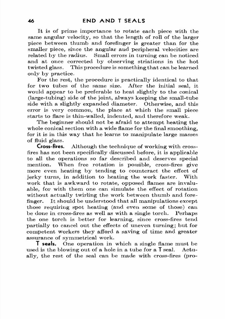
8/3/2019 Techniques of Glass Manipulation - Heldman
http://slidepdf.com/reader/full/techniques-of-glass-manipulation-heldman 58/144
46 END A N D T SEALS
It is of prime importance to rotate each piece with thesame angular velocity, so that the length of roll of the largerpiece between thumb and forefinger is greater than for thesmaller piece, since the angular and peripheral velocities arerelated by the rad ius. Small errors in turn ing can be noticedand at once corrected by observing striations in the hottwisted glass. This procedure is something th a t can be learnedonly by practice.
For the rest, the procedure is practically identical to thatfor two tube s of the same size. After th e initial seal, it
would appear to be preferable to heat slightly to the conical(large-tubing) side of the joint, always keeping the small-tubeside with a slightly expanded diam eter. Otherwise, and thiserror is very common, the place at which the small piecestarts to flare is thin-walled, indented, and therefore weak.
The beginner should not be afraid to attempt heating thewhole conical section w ith a wide flame for the final sm oothing,for it is in this way that he learns to manipulate large masses
of fluid glass.Cross-fires. Although the technique of working with cross-
fires has not been specifically discussed before, it is applicableto all the operations so far described and deserves specialmention. W hen free rotatio n is possible, cross-fires givemore even heating by tending to counteract the effect ofjerky turn s, in addition to heating the work faster. W ithwork that is awkward to rotate, opposed flames are invalu-able, for with them one can simulate the effect of rotationwithout actually twirling the work between thumb and fore-finger. It should be understood th a t all manipulations exceptthose requiring spot heating (and even some of those) canbe done in cross-fires as well as with a single torch . Perhapsthe one torch is better for learning, since cross-fires tendpartially to cancel out the effects of uneven turning; but for
competent workers they afford a saving of time and greaterassurance of symmetrical work.
T seals. One opera tion in which a single flame m ust beused is the blowing out of a hole in a tube for a T seal. Actu-ally, the rest of the seal can be made with cross-fires (pro-
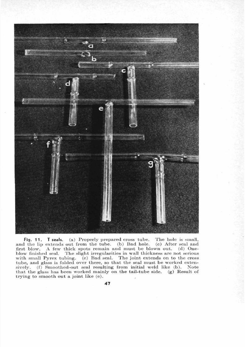
8/3/2019 Techniques of Glass Manipulation - Heldman
http://slidepdf.com/reader/full/techniques-of-glass-manipulation-heldman 59/144
Fig. 1 1 . T seals, (a) Prop erly prep ared cross tub e. Th e hole is small,an d the lip exten ds ou t from th e tu be , (b) Bad hole, (c) After seal andfirst blow. A few thick spo ts rem ain and m ust be blown ou t. (d) One-
blow finished seal. Th e slight irregu larities in wall thickn ess are no t seriouswith small Pyrex tubing , (e) Bad seal. Th e joint extends on to the crosstube, and glass is folded over there, so that the seal must be worked exten-sively, (f) Sm oo thed -out seal resulting from initial weld like (b). No teth at th e glass has been worked mainly on the tail-tub e side, (g) Resu lt oftrying to smooth out a joint like (e).
47
8/3/2019 Techniques of Glass Manipulation - Heldman
http://slidepdf.com/reader/full/techniques-of-glass-manipulation-heldman 60/144
48 END A N D T SEALS
fessional glass blowers often set up large T seals on a lathe) , bu tin most cases a single torch is preferable for the whole job.
Before star ting on a T seal, every thing should be inreadiness. Both pieces cf glass should be at hand . If theends are to be bulged, as is usually the case when they areto be attached to rubber, the bulges should be made beforethe seal is sta rte d . If the ends are to be short, it is some-times advisable to scratch them for breaking before anyobstructions are pre sen t. I t is wise to prov ide for an amplehandle of glass so that the job can be manipulated without
burning the hand s. About 6 to 8 in. is optimu m w ith glassup to 15 mm. Two plugs, previously tested for fit, shouldbe on hand for the open ends.
The tail tub e should have a squared end. I t may bethickened and flared slightly to advan tage . W hen this tub eis in readiness, the other tube is heated a t one spo t. ForPyrex No. 774 up to 10 mm, no preheating is necessary;for larger glass, the usual precautions are observed. H eating
for blowing ou t the hole is of prime importance. Almostall beginners blow ou t too large a hole. A very small flameis used. A novice should adjust his burner to w hat he thinksis the proper flame and then reduce it in size by at least half,
but keeping it a ho t flame. Th is flame is applied to thedesired spot without movement until the glass shrinks mark-edly. Th en a gentle puff—no hard blow—is given. A bulgeshould result. If it is smaller in diam eter than th e glassto be sealed on, no ha rm has been done. On the next heating,this bulge can be expanded by longer heating before blowing.If the bulge is too large, then the next heating should be withawery hot, small flame that melts the glass at the tip beforethe edges become fluid. This tip is the n blown out strongly.The final hole should ideally be made away from the wallof the tube, on the protuberance of a bulge extending out
from the tube. I t is preferable to have a hole th a t is slightlytoo small rather th an one a little too large. Th e tub e to besealed on will shrink down anyw ay when heated . True , itcan be flared out for a larger hole, but such a hole usuallyextends part way around the tube, weakening it and also
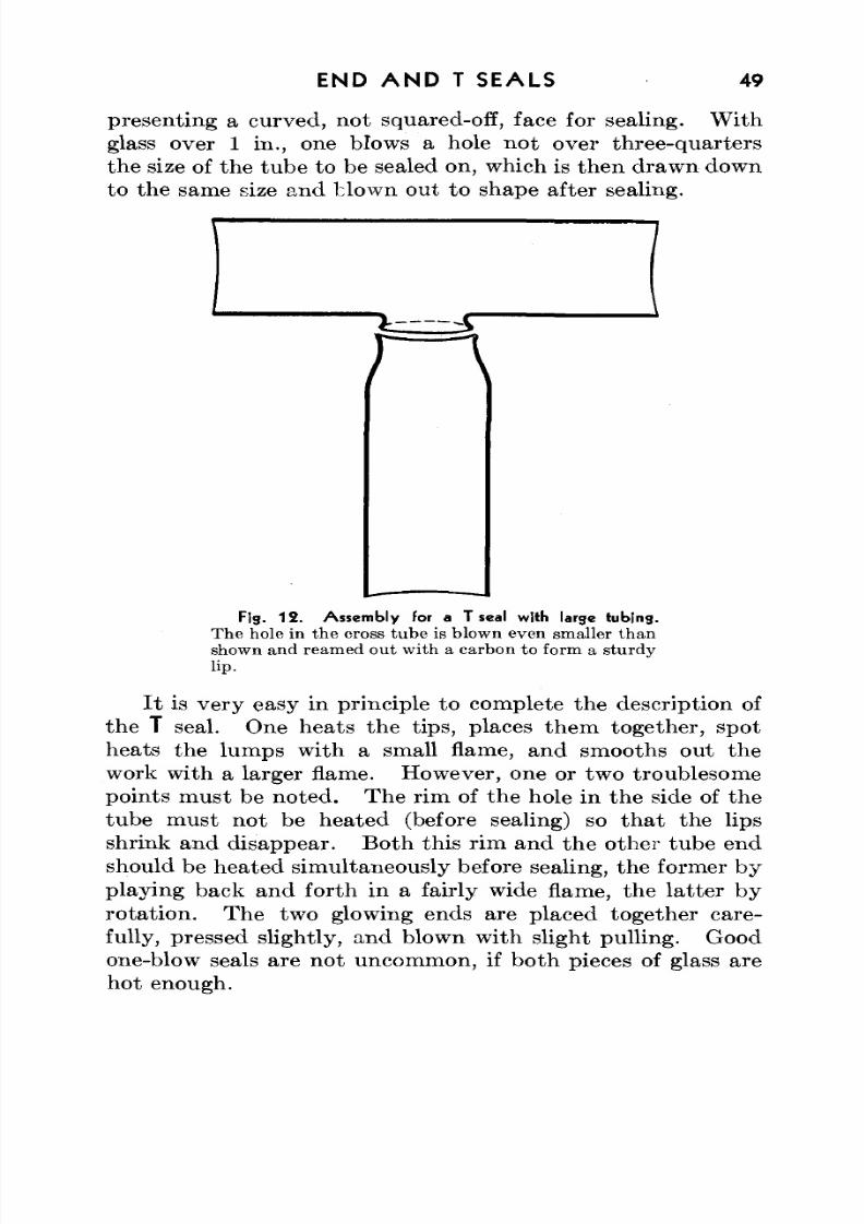
8/3/2019 Techniques of Glass Manipulation - Heldman
http://slidepdf.com/reader/full/techniques-of-glass-manipulation-heldman 61/144
END A N D T SEALS 49
presenting a curved , no t squared-off, face for sealing. W ithglass over 1 in., one blows a hole not over three-quartersthe size of the tube to be sealed on, which is then drawn downto the same size and blown out to shape after sealing.
Fig . 1 2 . Ass em bly for a T seal with large tubing .
The hole in the cross tube is blown even smaller thanshown and reamed out with a carbon to form a sturdylip.
It is very easy in principle to complete the description ofthe T seal. One heats the tips, places them together, spotheats the lumps with a small flame, and smooths out thework with a larger flame. How ever, one or two troublesomepoints m us t be noted. Th e rim of the hole in the side of thetube must not be heated (before sealing) so that the lipsshrink and disappear. Bo th this rim and the other tube endshould be heated simultaneously before sealing, the former by
playing back and forth in a fairly wide flame, the latter byrotatio n. The two glowing ends are placed toge ther care-fully, pressed slightly, and blown with slight pulling. Goodone-blow seals are not uncommon, if both pieces of glass arehot enough.
8/3/2019 Techniques of Glass Manipulation - Heldman
http://slidepdf.com/reader/full/techniques-of-glass-manipulation-heldman 62/144
50 END A N D T SEALS
Any resulting lum ps are hea ted in a small flame. If th ehole was blown properly in the first place, it will not be neces-
sary to hea t the stra igh t tube, except at the end of the lip. Ifthe straight tube is heated too much, it will become plastic,and the work will lose its alignment (three independent piecesof glass and only two hands to hold w ith!) . Another faultof such heating is that the glass at the curve is blown out toofar and hence becomes thinner.
W hen a nu m ber of T seals are to be made, especially w ithsmall tubing, it is advantageous to build a jig to hold the
straight tub e. W ith such a tool, it is possible to m anipu lateT seals by ro ta tio n and even to use cross-fires. The pos-sibility of bend ing the straig ht tub e is obviated . A simplejig m ay be m ade from two wall-type buret clamps or therm om -eter clamps.
y tubes. The construction of a Y tube differs from thatof a T tube only in that the "straight" tube is first bent andthe hole is blown on th e outside of the ben d. I t should beapparent that at this place the glass is thinnest, and Y sealsshould be attempted only on smooth, unflattened bends.
"Suck" seals. One technique for joining small side-arms tolarge glass rarely receives notice either because it is not gen-erally known or because of the hazards encountered if thefirst tr y is no t successful. This technique is the so-calledsuck seal, which can be a great aid to work in awkward spots
but is not recommended for use on valuable glass apparatuswithout first practicing.
To make a suck seal, the side-arm is first prepared bybordering the tip and placing in the tube a wad of cotton orglass wool, loose enough to allow air passage b ut tight enoughnot to move upon sucking. The bordered end should bekept just below the softening point while the larger glass isbeing heated with a very hot flame about the diameter of the
side-arm. W hen the heated spot is very hot and fluid, thesmall tube is placed on it so that it adheres to the hot glassand is at once sucked on strongly, so th at th e hot spot shouldexpand into the side-arm and bu rst . If it does not breakbut forms a very thin bubble, the cotton may be removed
8/3/2019 Techniques of Glass Manipulation - Heldman
http://slidepdf.com/reader/full/techniques-of-glass-manipulation-heldman 63/144
END A N D T SEALS 51
and a wire inserted to punctu re the bub ble. If properly done,the suck seal now requires only annealing; however, it may
be necessary to work the joint (in which case no advantagehas been gained over the ord inary T seal). Little chips ofglass from the bubble should be shaken out before the jointis worked.
If the spot has not been heated enough or if the suck is tooweak, the bubble cannot be broken and the joint is spoiled.It is then necessary to heat the weld, pull off the side-arm,and sta rt again, preferably using the ordinary procedu re. For
this reason the suck-seal technique is recommended only forproficient workers after much practice.
8/3/2019 Techniques of Glass Manipulation - Heldman
http://slidepdf.com/reader/full/techniques-of-glass-manipulation-heldman 64/144
CHAPTER VII
The Triple, Ring, or Inner Seal; the Dewar Seal
Supporting the glass. To someone who has attained pro-ficiency in making end and T seals, the ring seal should offerlittle th a t is novel in handling hot glass. Ring seals are madeproperly or spoiled previous to working, in the setting up.
Gravity and its consequences, weight and torque, must bereckoned with, and an y appreciable unsup ported w eight exert-ing a force on a flowing ring of hot glass must change thatring by thinning, twisting, bending, or otherwise moving it.A competent glass blower prevents this distortion, not byskillful manipulation, but by tying down the inner glass in aring seal so th a t it will be immovable w ith respect to th e tu bein which it is enclosed while the assembly is ho t. This poin t
cannot be stressed too strongly, and it is in fact the guidingrule for all types (but one) of ring seals: Tie down the innerglass.
Planning the work. A second rule, equally important, isto have proper working pa rts . Th e order of work should beplanned, and all pa rts of the assembly should be at hand . I tis particularly important that any tubing ends to be incorpo-
rated in a ring seal be squared off and that small bulbs blownfor the same purpose be symmetrical.
Most of the specific pieces of apparatus which require ringseals are commonly needed in the la bo rato ry ; none are beyondthe skill obtainable after a few weeks of practice at the glassbench. The examples have been chosen to include as m anytechniques as possible, thou gh it would be hopeless to atte m ptto list all the ingenious construction plans used by glass
blowers.Flow trap. Method I. A piece of glass which finds exten-
sive use in the laboratory is the trap diagramed in Fig. 13.There are at least four methods of making such a t rap. The
52
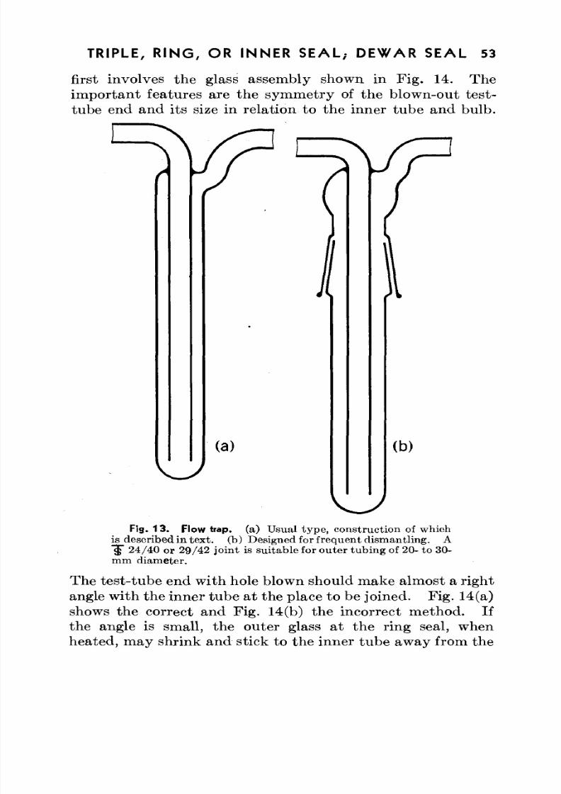
8/3/2019 Techniques of Glass Manipulation - Heldman
http://slidepdf.com/reader/full/techniques-of-glass-manipulation-heldman 65/144
TRIPLE, R IN G , OR INNE R SE A L; DEW AR SEAL 53
first involves the glass assembly shown in Fig. 14. Th eimportant features are the symmetry of the blown-out test-
tube end and its size in relation to the inner tube and bulb.
(a) (b)
Fig. 13 . Flow trap, (a) Usual type, construction of whichis described in tex t, (b) Designed for frequen t dism antlin g. A"§" 24 /40 or 29 /42 joint is suitable for oute r tubing of 20- to 30-mm diameter .
The test-tu be end with hole blown should m ake almost a rightangle with the inn er tube at the place to be joined. Fig. 14(a)shows the correct and Fig. 14(b) the incorrect method. Ifthe angle is small, the outer glass at the ring seal, whenheated, may shrink and stick to the inner tube away from the
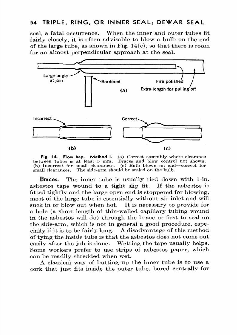
8/3/2019 Techniques of Glass Manipulation - Heldman
http://slidepdf.com/reader/full/techniques-of-glass-manipulation-heldman 66/144
54 TRIPLE, R IN G , OR INN ER SE AL ; DEW AR SEAL
seal, a fatal occurrence. W hen the inner and outer tubes fitfairly closely, it is often advisable to blow a bulb on the end
of the large tub e, as shown in Fig. 14 (c), so th a t the re is roomfor an almost perpendicular approach at the seal.
Large angleat join Bordered
(a )
Fire poJished
Extra length for pulling'off
shed /
Incorrect * Correct .
(b) (c)
Fig. 14. Flow trap. Method I. (a) Correct assembly where clearancebetween tub es is at least 5 m m. Braces and blow control not shown.(b) Inco rrect for small clearances, (c) Bu lb blown on end—correct forsmall clearances. Th e side-arm should be sealed on th e bu lb .
Braces. Th e inner tub e is usua lly tied down with 1-in.asbestos tape wound to a tight slip fit. If the asbestos isfitted tightly and the large open end is stoppered for blowing,most of the large tube is essentially without air inlet and willsuck in or blow out when ho t. I t is necessary to prov ide fora hole (a short length of thin-walled capillary tubing woundin the asbestos will do) through the brace or first to seal onthe side-arm, which is not in general a good procedure, espe-cially if it is to be fairly long. A disadvantage of this methodof tying the inside tube is th a t th e asbestos does not come ou t
easily after the job is done. W etting the tap e usually helps.Some workers prefer to use strips of asbestos paper, whichcan be readily shredded when wet.
A classical way of butting up the inner tube is to use acork that just fits inside the outer tube, bored centrally for
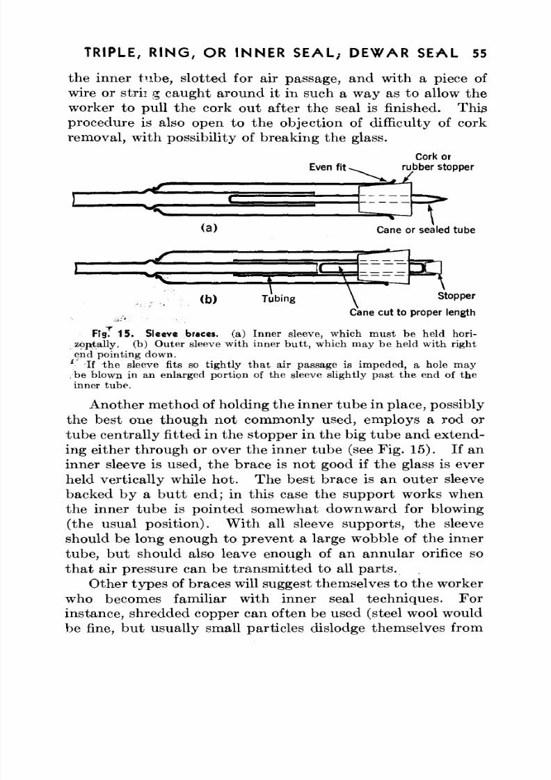
8/3/2019 Techniques of Glass Manipulation - Heldman
http://slidepdf.com/reader/full/techniques-of-glass-manipulation-heldman 67/144
TRIPLE, R IN G , OR INNER S EA L; DEW AR SEAL 55
the inner tube, slotted for air passage, and with a piece ofwire or strii g caught around it in such a way as to allow the
worker to pull th e cork out after the seal is finished. Thisprocedure is also open to the objection of difficulty of corkremoval, with possibility of breaking the glass.
Cork orEven fit - ^ rubber stopper
Cane or sealed tube
( b ) Tubing \ Stopper
Cane cut to proper length
Fig. 15. Sleeve braces, (a) Inner sleeve, which must be held hori-zoptally. (b) O uter sleeve with inner b u tt, which m ay be held with rightend pointing down.
JIf the sleeve fits so tightly that air passage is impeded, a hole may
be blown in an enlarged portion of the sleeve slightly past the end of theinner tube.
Another m ethod of holding the inn er tu be in place, possiblythe best one though not commonly used, employs a rod ortub e centrally fitted in the stopper in the big tub e and extend-
ing either thro ugh or over th e inner tube (see Fig . 15). If aninner sleeve is used, the brace is not good if the glass is everheld vertically while ho t. The best brace is an outer sleevebacked by a butt end; in this case the support works whenthe inner tube is pointed somewhat downward for blowing(the usual position). W ith all sleeve sup po rts, the sleeveshould be long enough to prevent a large wobble of the innertube, but should also leave enough of an annular orifice so
that air pressure can be transmitted to all parts.O ther typ es of braces will suggest themselves to the worker
who becomes familiar with inner seal techniques. Forinstance, shredded copper can often be used (steel wool wouldbe fine, but usually small particles dislodge themselves from
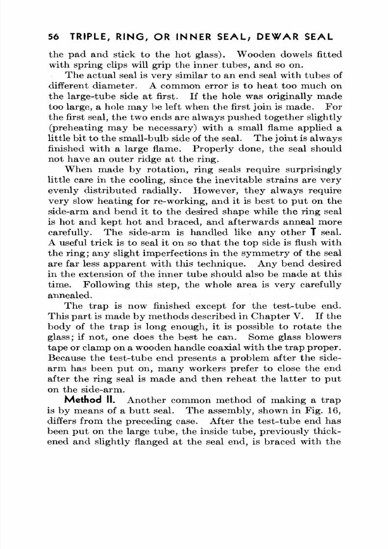
8/3/2019 Techniques of Glass Manipulation - Heldman
http://slidepdf.com/reader/full/techniques-of-glass-manipulation-heldman 68/144
56 TRIPLE, R IN G , OR INN ER S EA L; DEW AR SEAL
the pad and stick to the hot glass). W ooden dowels fittedwith spring clips will grip the inner tubes, and so on.
The actual seal is very similar to an end seal with tubes ofdifferent diam eter. A common error is to heat too much onthe large-tube side at first. If the hole was originally madetoo large, a hole m ay be left when the first join is m ade. Forthe first seal, the two ends are always pushed together slightly(preheating may be necessary) with a small flame applied alittle bit to the small-bulb side of the seal. Th e join t is alwaysfinished with a large flame. Proper ly don e, the seal should
not have an outer ridge at the ring.W hen made by ro tation , ring seals require surprisingly
little care in the cooling, since the inevitable strains are veryevenly distribu ted radially. How ever, the y always requirevery slow heating for re-working, and it is best to put on theside-arm and bend it to the desired shape while the ring sealis hot and kept hot and braced, and afterwards anneal morecarefully. Th e side-arm is handled like any other T seal.
A useful trick is to seal it on so that the top side is flush withthe ring ; any slight imperfections in the sy m m etry of the sealare far less appa ren t with this techn ique. Any bend desiredin the extension of the inner tube should also be made at thistime. Following this step, the whole area is very carefullyannealed.
The trap is now finished except for the test-tube end.
This par t is made by methods described in Chap ter V. If thebody of the trap is long enough, it is possible to rotate theglass; if not, one does the best he can. Some glass blowerstape or clamp on a wooden handle coaxial with th e tra p proper.Because the test-tube end presents a problem after the side-arm has been put on, many workers prefer to close the endafter the ring seal is made and then reheat the latter to puton the side-arm.
Method II. Another common method of making a trapis by means of a b u tt seal. The assembly, shown in Fig. 16,differs from the preceding case. After the tes t-tu be end hasbeen put on the large tube, the inside tube, previously thick-ened and slightly flanged at the seal end, is braced with the
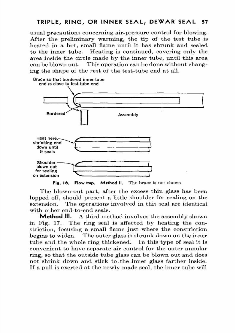
8/3/2019 Techniques of Glass Manipulation - Heldman
http://slidepdf.com/reader/full/techniques-of-glass-manipulation-heldman 69/144
TRIPLE, R IN G , OR INNE R SE AL ; DEW AR SEAL 57
usual precautions concerning air-pressure control for blowing.After the preliminary warming, the tip of the test tube isheated in a hot, small flame until it has shrunk and sealedto the inner tub e. H eating is continued, covering only thearea inside the circle made by the inner tube, until this areacan be blown ou t. This operation can be done without chang-ing the shape of the rest of the test-tube end at all.
Brace so that bordered inner-tubeend is close to test-tube end
Bordered AssemblyDHeat here,
shrinking enddown until
it seals
Shoulder-blown out
for sealing lr r-1on extension ^ \
Fig. 16 . Flow trap. Me thod II . Th e brace is not shown .
The blown-out part, after the excess thin glass has beenlopped off, should present a little shoulder for sealing on theextension. The operations involved in thi s seal are identicalwith other end-to-end seals.
Method III. A third m ethod involves the assembly shownin Fig. 17. Th e ring seal is affected by hea ting the con-striction, focusing a small flame just where the constrictionbegins to widen. The outer glass is shrunk down on the inner
tub e and the whole ring thickened. In th is typ e of seal it isconvenient to have separate air control for the outer annularring, so that the outside tube glass can be blown out and doesnot shrink down and stick to the inner glass farther inside.If a pull is exerted at the newly made seal, the inner tube will
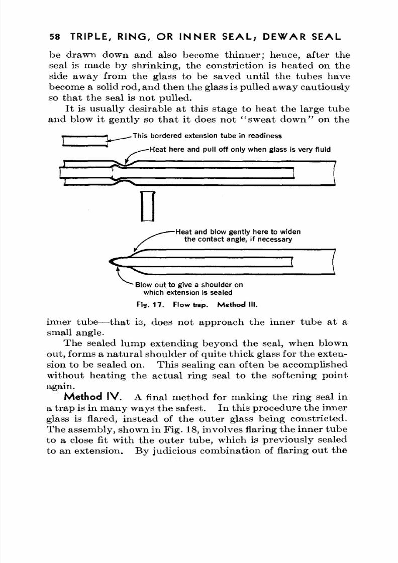
8/3/2019 Techniques of Glass Manipulation - Heldman
http://slidepdf.com/reader/full/techniques-of-glass-manipulation-heldman 70/144
58 TRIPLE, R IN G , OR INNE R S EA L; DEW AR SEAL
be drawn down and also become thinner; hence, after theseal is made by shrinking, the constriction is heated on theside away from the glass to be saved until the tubes havebecome a solid rod, and then the glass is pulled aw ay cautiouslyso that the seal is not pulled.
It is usually desirable at this stage to heat the large tubeand blow it gently so that it does not "sweat down" on the
This bordered extension tube in readiness
Heat here and pull off only when glass is very fluid
-Heat and blow gently here to widenthe contact angle, if necessary
Blow out to give a shoulder onwhich extension is sealed
Fig. 17. Flow trap. Method III.
inner tube—that is, does not approach the inner tube at asmall angle.
The sealed lump extending beyond the seal, when blownout, forms a natu ra l shoulder of quite thick glass for the ex ten-sion to be sealed on. Th is sealing can often be accomplishedwithout heating the actual ring seal to the softening pointagain.
Method IV. A final method for making the ring seal in
a trap is in m any ways the safest. In this procedure the innerglass is flared, instead of the outer glass being constricted.The assembly, shown in Fig . 18, involves flaring the inner tub eto a close fit with the outer tube, which is previously sealedto an extension. By judicious com bination of flaring out the
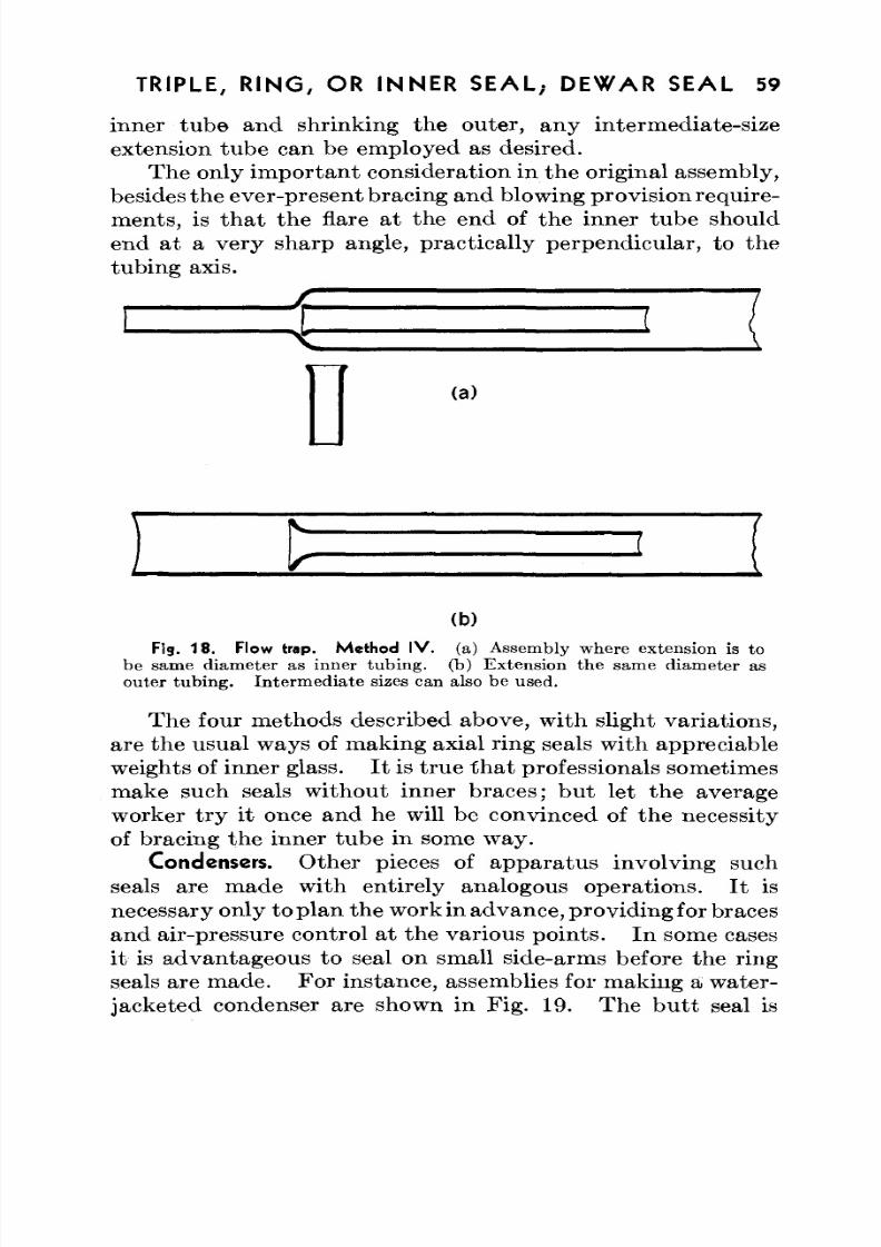
8/3/2019 Techniques of Glass Manipulation - Heldman
http://slidepdf.com/reader/full/techniques-of-glass-manipulation-heldman 71/144
TRIPLE, R IN G , OR INNE R SEAL,- DEW AR SEAL 59
inner tube and shrinking the outer, any intermediate-sizeextension tube can be employed as desired.
The only imp or tan t consideration in the original assembly,besides the ever-present bracing and blowing provision require-ments, is that the flare at the end of the inner tube shouldend at a very sharp angle, practically perpendicular, to thetubing axis.
(a )
(b)
Fis. 18 . Flow trap. Method IV. (a) Assembly where extension is tobe same diam eter as inner tubin g, (b) Extension the same diam eter asouter tub ing . Inte rm ed iate sizes can also be used.
The four methods described above, with slight variations,are the usual ways of making axial ring seals with appreciableweights of inner glass. I t is tru e th a t professionals sometimesmake such seals without inner braces; but let the averageworker try it once and he will be convinced of the necessityof bracing the inner tube in some way.
Condensers. O ther pieces of app aratu s involving suchseals are made with entirely analogous opera tions. I t is
necessary only to plan the work in advance, providing for bracesand air-pressure control at the various po ints. In some casesit is advantageous to seal on small side-arms before the ringseals are m ade . Fo r instance, assemblies for making a water-jacketed condenser are shown in Fig. 19. Th e b u tt seal is
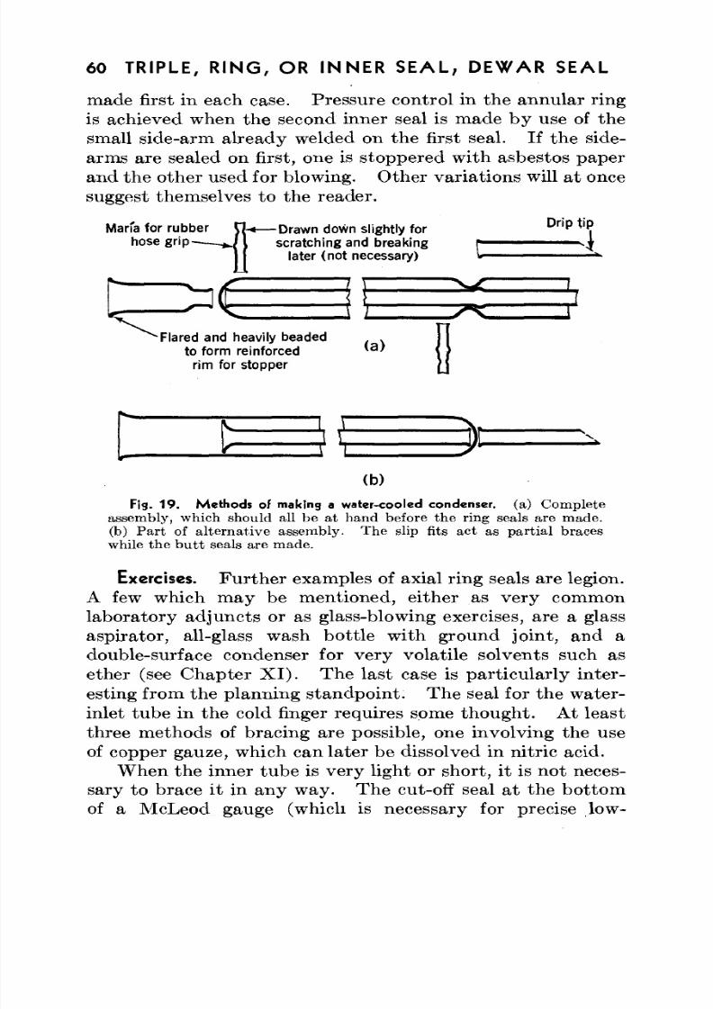
8/3/2019 Techniques of Glass Manipulation - Heldman
http://slidepdf.com/reader/full/techniques-of-glass-manipulation-heldman 72/144
60 TRIPLE, R IN G , OR INNER SEAL; DEWAR SEAL
made first in each case. Pressure control in the annular ringis achieved when the second inner seal is made by use of the
small side-arm already welded on the first seal. If the side-arms are sealed on first, one is stoppered with asbestos paperand the other used for blowing. Other variatio ns will at oncesuggest themselves to the reader.
Marfa for rubber KU— Draw n down slightly forD n p
*'•?
hose grip * / } scratching and breaking r
11 later (notnecessary) I
'Flared andheavily beaded . .
to form reinforced 'a
'
rim for stopper
J L
(b)
Fig. 19. Methods of making a water-cooled condenser, (a) C o m p l e t eassembly, which should all be at hand before the ring seals are made.
(b) Part of alternative assembly. The slip fits act as partial braces
while the butt seals are made.
Exercises. Further examples of axial ring seals are legion.A few which may be mentioned, either as very commonlaboratory adjuncts or as glass-blowing exercises, are a glassaspirator, all-glass wash bottle with ground joint, and a
double-surface condenser for very volatile solvents such as
ether (see Chapter XI). The last case is particularly inter-esting from the planning standpoint. The seal for the water-inlet tube in the cold finger requires some thought. At least
three methods of bracing are possible, one involving the useof copper gauze, which canlater be dissolved in nitric acid.
When the inner tube is very light or short, it is not neces-sary to brace it in any way. The cut-off seal at the bottomof a McLeod gauge (which is necessary for precise low-
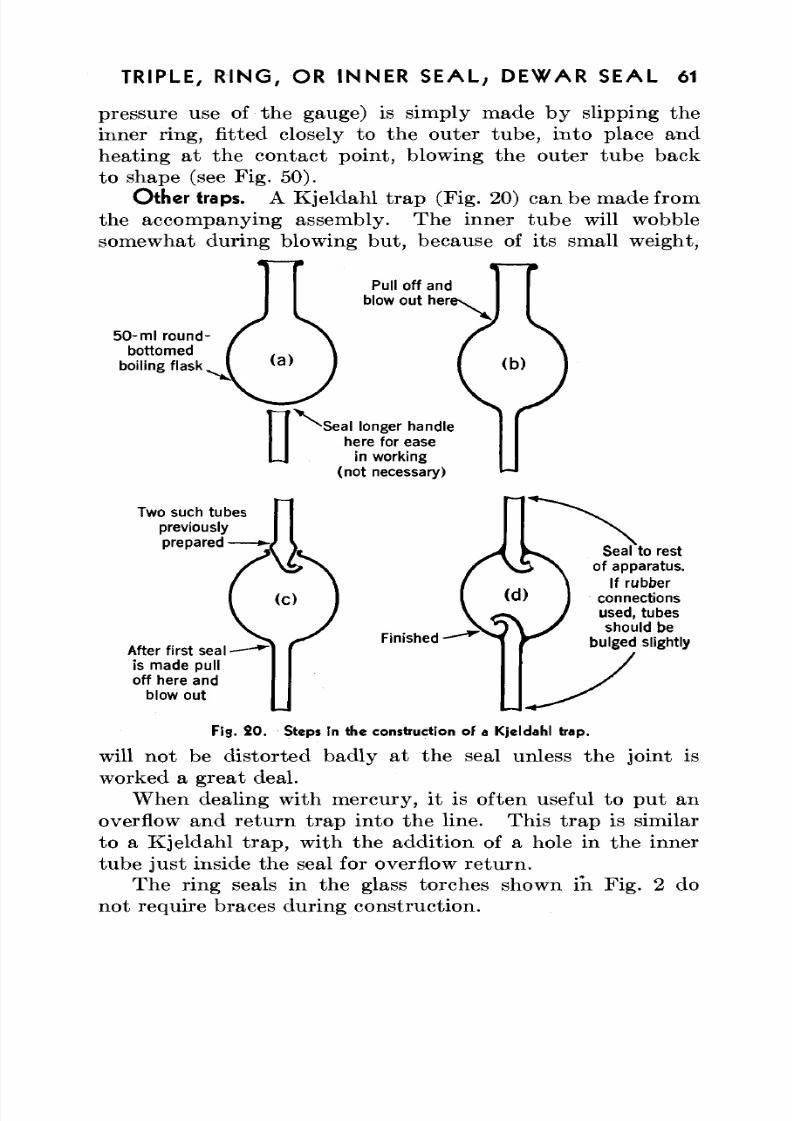
8/3/2019 Techniques of Glass Manipulation - Heldman
http://slidepdf.com/reader/full/techniques-of-glass-manipulation-heldman 73/144
TRIPLE, R IN G , OR INNER SEAL,. DEW AR SEAL 61
pressure use of the gauge) is simply made by slipping theinner ring, fitted closely to the outer tube, into place and
heating at the contact point, blowing the outer tube backto shape (see Fig. 50).O ther traps. A Kjeldahl trap (Fig. 20) can be m ade from
the accompanying assembly. Th e inner tub e will wobblesomewhat during blowing but, because of its small weight,
50 - m l r o u n d -
bottomed
boiling flask
Pull off and
blow out hen
Seal longer handle
here for ease
in working
(not necessary)
Two such tubes
previously
prepared —
Finished -
Seal to rest
of apparatus.
If rubber
connections
used, tubes
should be
bulged slightlyAfter first sealis made pull
off here and
blow out
Fig . SO. Steps in the construction of a Kjeld ahl trap.
will not be distorted badly at the seal unless the joint isworked a great deal.
W hen dealing with m ercury, it is often useful to pu t an
overflow and re turn tra p into the line. Th is tr ap is similarto a Kjeldahl trap, with the addition of a hole in the innertube just inside the seal for overflow return.
The ring seals in the glass torches shown in Fig. 2 donot require braces during construction.
8/3/2019 Techniques of Glass Manipulation - Heldman
http://slidepdf.com/reader/full/techniques-of-glass-manipulation-heldman 74/144
62 TRIPLE, R IN G , OR INNE R S EA L; DEWA R SEAL
Ring seals through the side of a tube. Ring sea ls through
the side of a tube are formally similar to T seals. The seal
is made by the butt technique, with the inner tube veryfirmly braced . A shoulder should be blown out for th eextension-tube seal; that is, the extension tube should not bewelded direc tly onto the seal. Such seals are really quite easyto make if the inner tub e is imm ovable. How ever, they arethe most strained of all glass joints, and it is necessaryto keep the whole area, including a w ide ring of th e o uter tub e,hot while the glass is being worked and to cool the heated
area very slowly and evenly.Gas flowmeter. As an example of the use of th is type of
seal, a gas flowm eter is shown in Fig. 21 . Th is flowm eterhas several advantages: It is easy to mount, sturdy, andcompact, and it has several different ranges because of thereplaceable capillaries. If the inner tu be is small withrespect to the outer, only the inner-tube liquid height needbe read except in very precise work.
Dewar seal. One other typ e of seal th at , though notformally similar, involves the same basic techniques as thetriple seal is th e Dewar seal. In thi s type of seal, two glasstubes, usu ally coaxial, one inside the o ther, are sealed togetherat one end, but without an extension jutting through as in aring seal. In m any cases it is feasible to make a ring seal,cutting the extension off close to the seal, rather than the
Dewar-type weld.In setting up a D ewar seal, it is necessary to brace the glass
tightly, providing for air-pressure control, and to have theglass rims to be sealed in close and even jux tapo sition . Theinner and oute r lips should be cut squa re. Following thisstep, one procedure is to flange out the inner tube to a rightangle, so that the lip hits the outer tube edge, as in Fig.22(a). Th e ou ter lip can even be flanged back on itself, as in
Fig. 22 (d).It may be necessary, for the initial join, to use a little
welding rod. No new typ es of operations are involved inthe blowing or annealing. Practic ally . the only stumblingblock with properly set up and braced work is overheating
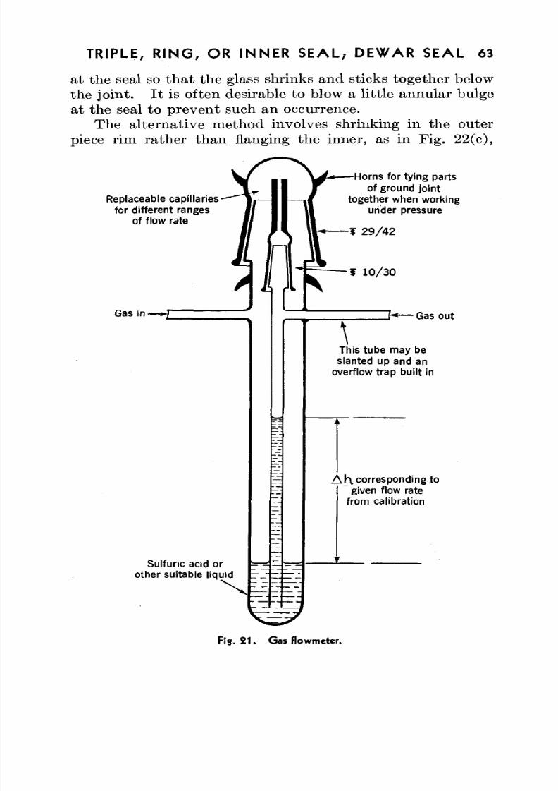
8/3/2019 Techniques of Glass Manipulation - Heldman
http://slidepdf.com/reader/full/techniques-of-glass-manipulation-heldman 75/144
TRIPLE, R IN G , OR INNE R S EA L; DEWA R SEAL 63
at the seal so that the glass shrinks and sticks together belowthe joint. I t is often desirable to blow a little annu lar bulge
at the seal to prevent such an occurrence.The alternative method involves shrinking in the outerpiece rim rath er th an flanging the inner, as in Fig. 22 (c),
Replaceable capillariesfor different ranges
of flow rate
Gas in -
Sulfunc acid or
other suitable liquid
•Horns for tying partsof ground joint
together when workingunder pressure
• f 2 9 / 4 2
f 10/30
\
_ H — Gas out
This tube may beslanted up and an
overflow trap built in
A ^ l corresponding togiven flow rate
from calibration
Fig. 2 1 . Gas flowm eter.
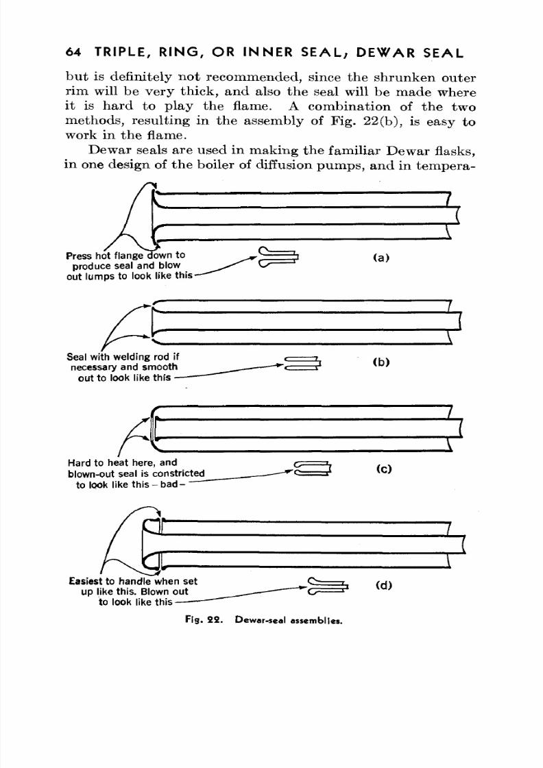
8/3/2019 Techniques of Glass Manipulation - Heldman
http://slidepdf.com/reader/full/techniques-of-glass-manipulation-heldman 76/144
64 TRIPLE, R IN G , OR INN ER S EA L; DEW AR SEAL
but is definitely not recommended, since the shrunken outerrim will be very thick, and also the seal will be made where
it is ha rd to play the flame. A com bination of the twomethods, resulting in the assembly of F ig. 22 (b), is easy towork in the flame.
Dewar seals are used in making the familiar Dewar flasks,in one design of the boiler of diffusion pumps, and in tempera-
Press hot flange down to
produce seal and blow
out lumps to look like this
(a)
Seal with welding rod if
necessary and smooth
ou t to look like this -
(b)
Hard to heat here, and
blown-out seal is constricted
t o l o o k l i ke t h i s - b ad -
(0
Easiest to handle when set
up like this. Blown out
to look like this
(d)
Fig. 2 2 . Dewar-seal assemblies.
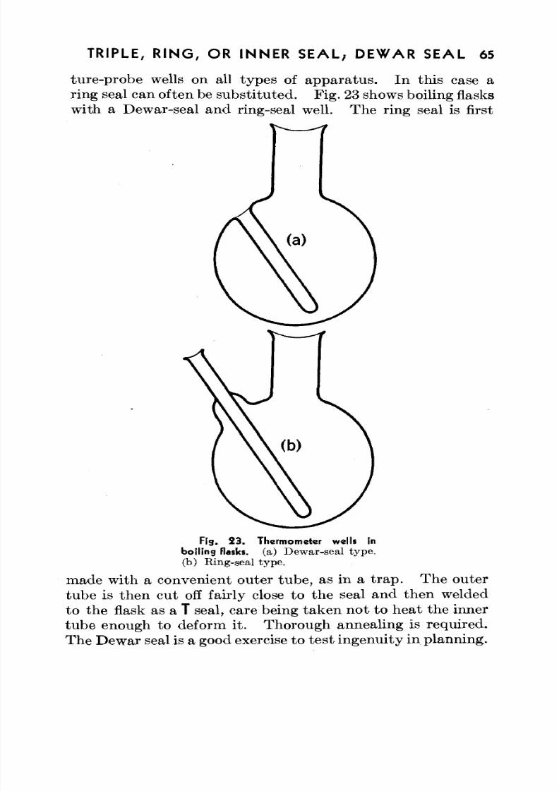
8/3/2019 Techniques of Glass Manipulation - Heldman
http://slidepdf.com/reader/full/techniques-of-glass-manipulation-heldman 77/144
TRIPLE, R IN G , OR INNE R S EA L; DEW AR SEAL 65
ture-probe wells on all types of app ara tus . In this case aring seal can often be subs titu ted . Fig. 23 shows boiling flasks
with a Dew ar-seal and ring-seal well. Th e ring seal is first
Fig. 23. Thermometer wells in
boiling flasks, (a) D ew ar -se al ty pe ,
(b) Ring-seal typ e .
made with a convenient outer tub e, as in a tr ap . Th e outertube is then cut off fairly close to the seal and then weldedto the flask as a T seal, care being tak en n ot to h ea t the innertub e enough to deform it. Thorough annealing is required.Th e Dewar seal is a good exercise to tes t ingenu ity in planning .
8/3/2019 Techniques of Glass Manipulation - Heldman
http://slidepdf.com/reader/full/techniques-of-glass-manipulation-heldman 78/144
CHAPTER VIII
Use of the Hand Torch
Situations requiring hand torch. Many s i tua t ions occur
in which it is desirable to keep glass in place and use a m ovableflame; on the vacuum bench it is necessary. Though theprinciples involved are the same as for stationary name-
movable glass operations, a few points should be specificallynoted. The first rule is always to have welding rod at han d.Two- or 3-mm cane, drawn down from larger rod if necessary,is not an accessory to be ashamed of; indeed, in finishingclosed circuits, professionals use it liberally.
Only the simplest operations should be attempted inplace. End seals w ith both tubes of approxim ately the
same diameter and T seals are, with practically no exceptions,the whole repertory of in-place glass blowing.From the esthetic standpoint, since hot glass sags, end
seals should be made with the tubes vertical and T's upright.This procedure should especially be followed with largerglass, which must be worked a good deal to remove lumps.However, hand-torch work is seldom neat anyway withlarge tubin g. Presum ably such work is always clamped
tightly in place and is not subject to mechanical shock,so that thin spots are not too troublesome.
Both glass ends clamped. Two cases must be considered:That in which both pieces of glass are clamped in place,and th at in which one piece is free.., In the first case it isof prime importance that the ends be squared off and clampedin juxtaposition, with a slight pressure tending to push themtoge ther. A s'gen tle hea ting is applied all around, the glass
should shove together. Once sealed, such a joint is easyto finish—first the pinpoint flame to fuse the kinks, thena larger flame for finishing, and finally even application ofheat to the whole joint to bring it to the softening tem perature ,
66
8/3/2019 Techniques of Glass Manipulation - Heldman
http://slidepdf.com/reader/full/techniques-of-glass-manipulation-heldman 79/144
USE OF THE H A N D TORCH 67
so th at strains due to clamps are relieved. The possibilitythat holes will be left in the original seal is always present; in
such a case it is necessary to use welding rod, b ut as sparinglyas possible to prev ent lumpiness. I t is always bette r toblow bulges than to leave lumps of glass in a seal.
One end free. If a short, light, or easy-to-handle end ofglass is to be sealed on at the side or bottom of another pieceof stationary glass, it is often convenient to hold the end inone hand, rather than clamping it, while manipulating thetorch with the othe r. In this way the original seal can
usually be effected w ithou t th e use of welding rod, by bendingor shoving at the plastic jun ctu re. Th e rubb er-tubing blow-piece should either be attached to the stationary glass orhang from the other end without exerting appreciable torquefor the hand to overcome. This method is more rapid thanthe preceding one, but it requires more practice and skill.The technique should not be attempted with short leads tobe sealed on top of station ary glass. H ot-air burn s can be
quite serious.When a seal made in the above manner is subsequently
clamped, it is desirable to heat a ring of glass (not necessarilyat the seal) to the softening point. Strains due to clampingare a common cause of glass failure. I t should be a generalrule to clamp glass rigidly in as few places as is consistentwith applied weight and bending force. Glass should never
be clamped directly to metal, except with the special clampsfor spherical joints.
Closing a circuit. Closing a circuit of tub ing is an interest-ing application of the hand torch. The method usuallyrecommended is to insert a prefabricated piece in place, oneend being joined temporarily with a short rubber sleeve.The other end is sealed, the rubber cut off with a razorblade, and the final seal made . Here welding glass is always
needed. The lazy m an 's va rian t of this technique is to joinone end without blowing, make the other seal, and thenreturn to the first, reheating very slowly, since the unblownweld is almost certainly strained.
Closed circuits are particularly susceptible to cooling
8/3/2019 Techniques of Glass Manipulation - Heldman
http://slidepdf.com/reader/full/techniques-of-glass-manipulation-heldman 80/144
68 USE OF THE HAND TORCH
strain s. After all the seals are m ade , a leng th of th e smallestglass in the circuit should be kept at the softening point for
some tim e. If permissible in the equ ipm ent design, it isdesirable to include an expansion coil or bellows in the closedcircuit.
Sealing in vacuo. One hand -torch technique th at deservesspecial mention is sealing off in vacuo. This technique isnot difficult if the constriction is prop erly m ade. I t shouldbe long and tapered , if possible, w ith fairly thick walls. Asoft flame is moved around the constriction, with continuous
pull on th e ap pa ra tus to be sealed off. Even peripheralheating will give a seal that is not sucked in on one side.It is possible to seal off tubing up to 10-mm o.d. without aconstriction in this way.
If the evacuated vessel is tightly supported and cannotbe pulled away, th e job is more difficult. I t is desirable tohave a constriction as long and as narrow of bore as possible.A long, thin section can then be heated until it sucks andshrinks into a rod. The middle of this section is then strong lyheated and pulled away with a tweezers or another piece of«glass, severing the connection.
Annealing seal-offs is a rather touchy procedure, since therelatively thin glass away from the seal cannot be heated tothe give po int, lest it suck in. However, annealing isapparently not too critical with Pyrex No. 774.
Special torches. On some glass blowers' benches onesees a special torch for in-place seals on tubing up to 3^-in.
o.d. I t is really a movable m inia ture version of cross-fires,and by playing it about the seal one is able to heat thewhole periphery quite evenly. Such a double-flame torch ,sometimes called a splicing torch, is not common, but it doeshave its uses where much in-place work is done. M ostworkers have never seen a splicing torch but would probably
agree that it is a superior tool to the usual single flame forsmoothing out seals and vacuum seal-offs. Anyone with alittle ingenuity, time, and skill can design and build one frommetal or glass. The splicing torch in Fig. 1 is made from thebase (including mixing chamber) of a commercial torch and
8/3/2019 Techniques of Glass Manipulation - Heldman
http://slidepdf.com/reader/full/techniques-of-glass-manipulation-heldman 81/144
USE OF THE H A N D TORC H 69
two inexpensive commercial tips brazed on to bent coppertubes.
High-vacuum leaks. The important problem of sealingtiny leaks in systems requiring high vacuum is properlytreated under hand-torch manipulation, since most vacuumequipment is clamped in place. Before describing thetechniques, how ever, a digression in to the causes of such leaksand the methods of finding them will be of value.
Leaks which will hold liquid bu t n ot vacuu m are comm onlycaused by occlusion of asbestos, iron oxide, or other foreign
matter in a joint and sometimes by a hole in the originalseal that has not been worked enough, especially wheremuch welding rod has been employed. Their occurrenceis noted by pumping out the system and measuring theultimate vacuum or by shutting out the pump and watchingfor a rise in pressure . Neither of these m ethods tells theexact leak spot, which can be found with a spark coil (alsoknown as a Tesla coil, brush discharge, leak tester, vacuum
tester, or dete cto r). The discharge from the tip of theinstrument, when placed against a glass container, willstart a weak reddish glow discharge on the inside of the glasswhen the pressure is diminished to abou t 1 mm H g. This glowbecomes stronger as the pressure is lowered further anddisappears at about 5 X 10~
4mm. If mercury is present,
the discharge is purple at higher pressures and blue below1CT
1mm.
If there is a capillary leak in the glass, the spark coil willinduce a very bright, practically white, discharge through it.A very strong spark will actually punch a hole through athin spot, but this is just as well, since such thin glass isliable to be troublesome.
To repair such a leak, the system is let down to atmos-pheric pressure, blow control provided, and the bad spot
heated with the hand torc h. If the leak was caused byinsufficient working of the joint, it can usually be cured byheating and blowing a few tim es. If, how ever, foreignmatter is embedded in the glass, it is necessary to cover overthe leak path with a do t of welding rod . In an y case the glass

8/3/2019 Techniques of Glass Manipulation - Heldman
http://slidepdf.com/reader/full/techniques-of-glass-manipulation-heldman 82/144
70 USE OF THE HAND TORCH
should be thickened by heating strongly, and then it shouldbe thoroughly annealed.
Leaks which occur in glass th at is no t to be hea ted or cooledand in which chemical cleanliness is not important can besealed up with picein, sealing wax, or de Khotinsky cement.The application is made by warming the glass (not the wax),applying the stick of sealing compound, and gently heatingthe applied daub to smooth it over.
8/3/2019 Techniques of Glass Manipulation - Heldman
http://slidepdf.com/reader/full/techniques-of-glass-manipulation-heldman 83/144
CHAPTER IX
Other Operations
A NUMBER of miscellaneous glass operations that have* x
not been covered in the previous chapters crop up fromtime to time in the laborato ry . A brief discussion of mostof these operations appears valuable, since they are, in the
main, simple enough to be mastered b y the average technician.A few more manipulations, which are more advanced butwhich nonetheless must sometimes be used in devising certaintypes of equipment, are also included.
Constrictions. Constrictions in tubing , such as in manom -eter tubes , are very commonly encountered. Th e obviousvariable ratios are (1) original bore to constricted bore and(2) original wall thickness to constriction wall thickness.It is possible to va ry these ratios w ithin wide limits. Ratio(1) is determined by the flow rate desired; ratio (2) is thestrength factor and should be large for small tubing and atleast unity for large tubing (constricted bore over 10 mm).Diagrams of different types of constrictions are given inFig. 24.
Types a and b are made by heating a tube with rotation
and slight compressional pressure of bo th hand s. No blowingis necessary if the heating is done carefully. If a is desired,but the glass is pushed so much that b results, the tube canbe removed from the flame and pulled slightly. I t may thenbe necessary to reheat it in a large flame and blow to thickenthe glass at the edge of the constriction, which will becomethin when pulled. A constriction th a t has been shrunk toofar can be blown gently to the desired orifice unless it has
actually shrunk into a rod.It is not feasible, with large glass, to make a constriction
of type a or b, since the large lump of solid glass is apt to bestrained. Large glass is hand led as in pulling a point, mak ing
71
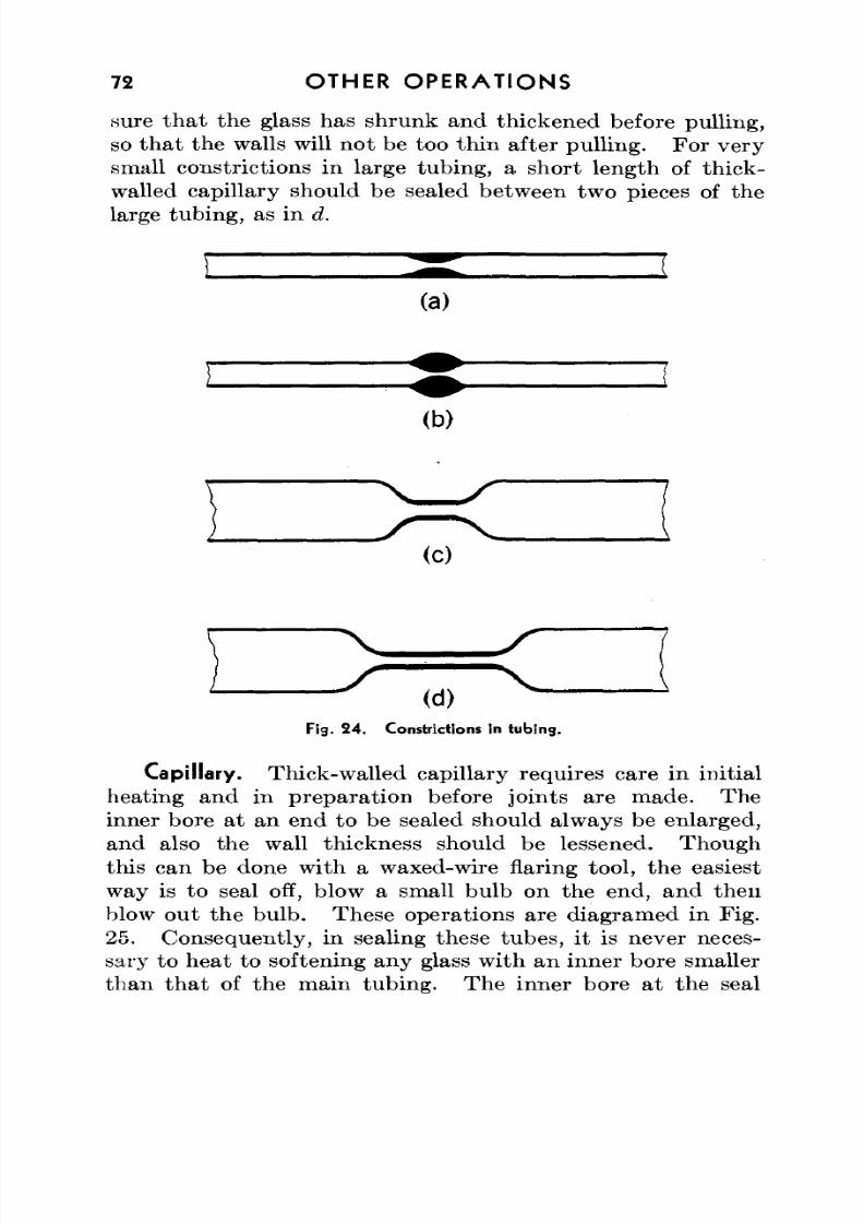
8/3/2019 Techniques of Glass Manipulation - Heldman
http://slidepdf.com/reader/full/techniques-of-glass-manipulation-heldman 84/144
72 O T H E R O P E R A T I O N S
sure that the glass has shrunk and thickened before pulling,so th at th e walls will no t be too th in after pulling. Fo r very
small constrictions in large tubing, a short length of thick-walled capillary should be sealed between two pieces of thelarge tubing, as in d.
(a)
(b)
X S
Fig. 2 4 . Constrictions in tubin g .
Capillary. Thick-walled capillary requires care in initialheating and in preparation before joints are m ade. Theinner bore at an end to be sealed should always be enlarged,and also the wall thickness should be lessened. Thoughthis can be done with a waxed-wire flaring tool, the easiest
way is to seal off, blow a small bulb on the end, and thenblow out the bu lb. These operations are diagramed in Fig.25. Consequently, in sealing these tubes, it is never neces-sary to heat to softening any glass with an inner bore smallerthan th at of the main tubing . Th e inner bore at the seal
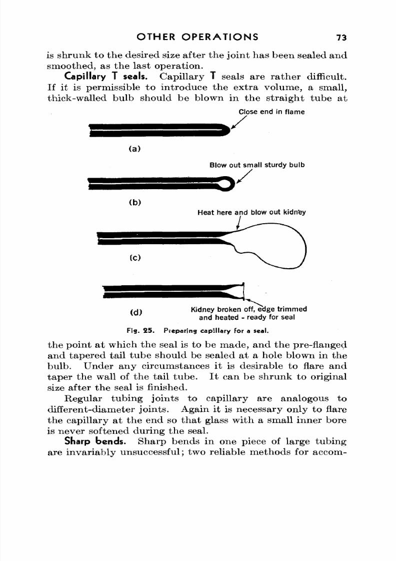
8/3/2019 Techniques of Glass Manipulation - Heldman
http://slidepdf.com/reader/full/techniques-of-glass-manipulation-heldman 85/144
OTHER OP ER ATIO NS 73
is shrun k to the desired size after the join t has been sealed andsmoothed, as the last operation.
Capillary T seals. Capillary T seals are ra th er difficult.If it is permissible to introduce the extra volume, a small,thick-walled bulb should be blown in the straight tube at
Close end in flame
y(a)
Blow out small sturdy bulb
(b)Heat here and blow out kidn'ey
(C)
< A \ Kidney broken off, edge trim m edand heated - ready for seal
Fig. 25 . Preparing cap illary for a seal.
the point at which the seal is to be made, and the pre-flangedand tapered tail tube should be sealed at a hole blown in thebulb. Under any circumstances it is desirable to flare andtape r the wall of the tail tube . I t can be shrunk to originalsize after the seal is finished.
Regular tubing joints to capillary are analogous to
different-diameter join ts. Again it is necessary only to flarethe capillary at the end so that glass with a small inner boreis never softened during the seal.
Sharp bends. Sharp bends in one piece of large tubingare invariably unsuccessful; two reliable methods for accom-
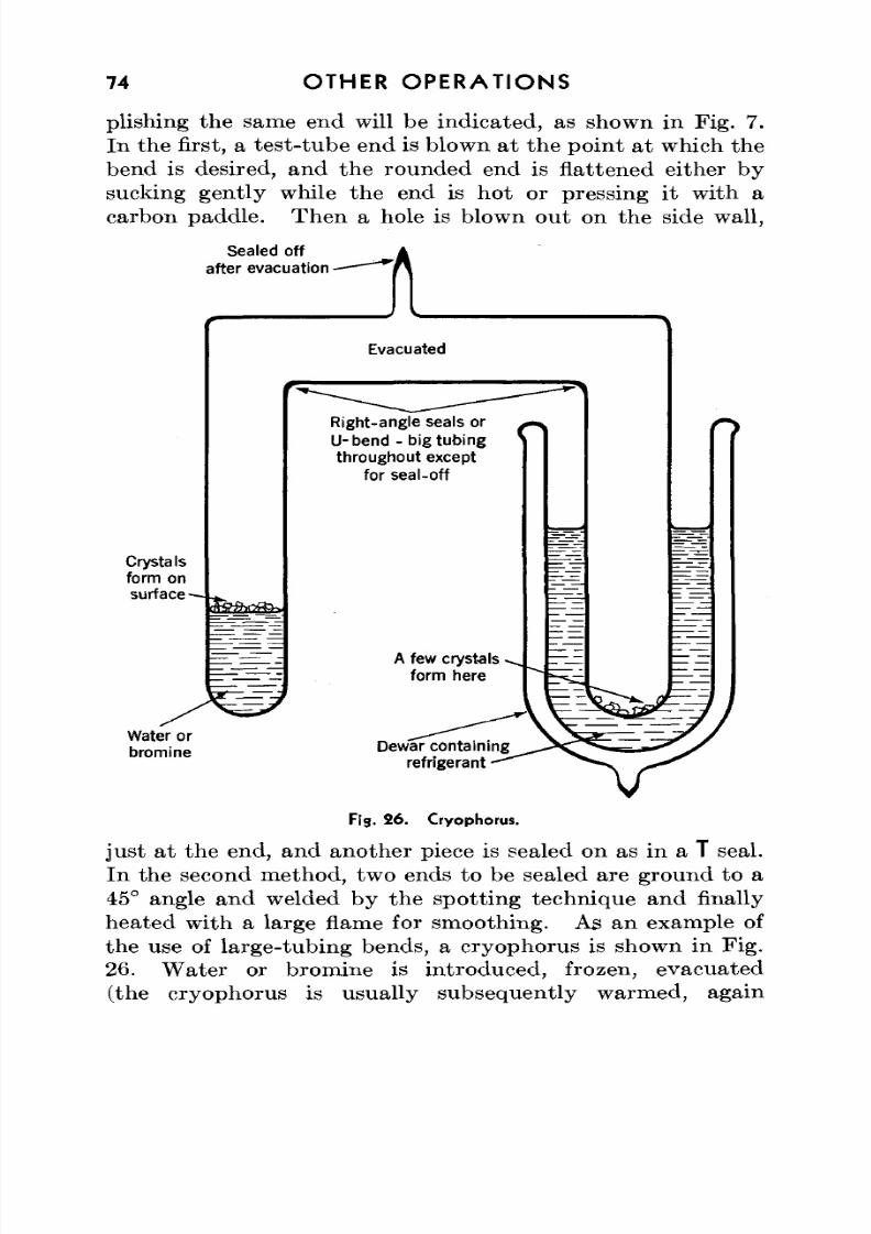
8/3/2019 Techniques of Glass Manipulation - Heldman
http://slidepdf.com/reader/full/techniques-of-glass-manipulation-heldman 86/144
74 OTHER OPERATIONS
plishing the same end will be indicated, as shown in Fig. 7.In the first, a test-tube end is blown at the point at which the
bend is desired, and the rounded end is flattened either bysucking gently while the end is hot or pressing it with acarbon paddle. Then a hole is blown out on the side wall,
Sealed off
after e vacua tion - t
Crystals
form on
sur face-
Evacuated
Right-angle seals or
U-bend - big tubing
throughout except
for seal-off
A few crystals •
form here
Water or
bromineDewar containing
refrigerant
Fig. 26. Cryophorus.
just at the end, and another piece is sealed on as in a T seal.In the second method, two ends to be sealed are ground to a
45° angle and welded by the spotting technique and finallyheated w ith a large flame for smoothing. As an example ofthe use of large-tubing bends, a cryophorus is shown in Fig.26. W ater or bromine is introduced, frozen, evacuated(the cryophorus is usually subsequently warmed, again
8/3/2019 Techniques of Glass Manipulation - Heldman
http://slidepdf.com/reader/full/techniques-of-glass-manipulation-heldman 87/144
OTHER OP ER AT IONS 75
frozen, and pumped to outgas it), and sealed in vacuo. I tserves as a nice demonstration of the heat of vaporization,
since a refrigerant placed about the empty arm almost atonce causes the liquid in the other a rm to freeze at its surface.Coils. Glass coils may be made in the laboratory in two
ways. W ith either m ethod success is no t assured, since theproper heating and turning "f ee l" is rather touchy. A verylarge, even flame (or vertical cross-fires) is desirable, andeven then it takes specialized techniques to coil tubing over10-mm o.d.
Free-hand. In the first method, the glass is worked free-hand . A sharp right-angle bend is made far enough from theend—say, 6 or 8 in.— to leave a handle of tub ing . Thenthe tubing is fed with one hand through the wide flame whilethe other rota tes the handle. If the flame, feed rate, androtat ion are nicely balanced, an even coil will result. Oftenthe first two or three turns are not quite circular; they maybe cut off and a new end sealed on.
Mandrel. In the other method, a m andrel is used. Amandrel is a glass or metal cylinder of slightly under thedesired diameter (sometimes slightly tapered to facilitateremoval of the coil), wrapped evenly with wet asbestos paper,smoothed down at the seams, and allowed to dry thoroughly.Nickel or carbon mandrels need no t be asbestos-covered. Alittle water-glass (sodium silicate) solution may be painted
on the asbestos. A m etal m andrel can be notched at th eend to start the coil; the end of the tube to be coiled is fusedto the tip of a glass m and rel. If available, rollers should beused to steady th e weight of the m andrel while the glass is beingheated, as in the preceding method, and rolled on the largecylinder. In general, a new asbestos covering must be usedfor each coil. A coil is designed and the mandre l pu t togetheron one day, and the mandrel is used the next day after
drying.Glass coils find uses in condensers, to take up strain in
closed circuits, to provide flexibility in all-glass shakingdevices, and to bring water through long paths for high-voltage cooling requirements.
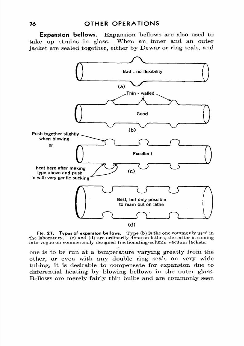
8/3/2019 Techniques of Glass Manipulation - Heldman
http://slidepdf.com/reader/full/techniques-of-glass-manipulation-heldman 88/144
76 OTHER OPERATIONS
Expansion bellows. Expansion bellows are also used totake up strains in glass. W hen an inner and an outer
jacket are sealed together, either by Dewar or ring seals, and
r\
G Bad • no flexibility
(a)
..Thin - walled
Push together slightly
when blowing
or
heat here after makingtype above and push
in with very gentle sucking
u u uBest, but only possibleto ream out on lathe
n n__n(d)
Fig. 27. Types of expansion bellows. T yp e (b) is th e one comm only used inthe laboratory, (c) and (d) are ordinarily done on lathe s; th e latter is cominginto vogue on commercially designed fractionating-column vacuum jackets.
one is to be- run at a tem perature vary ing greatly from theother, or even with any double ring seals on very widetubing, it is desirable to compensate for expansion due todifferential heating by blowing bellows in the outer glass.Bellows are merely fairly thin bulbs and are commonly seen
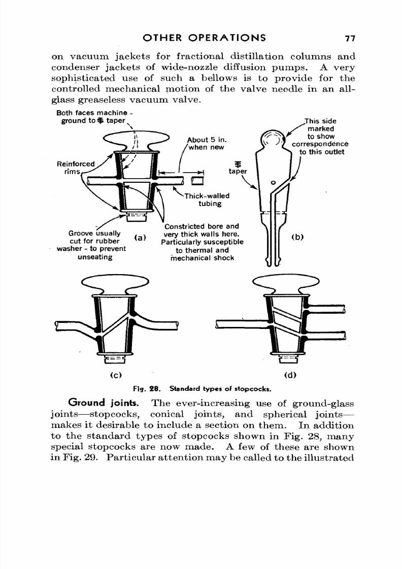
8/3/2019 Techniques of Glass Manipulation - Heldman
http://slidepdf.com/reader/full/techniques-of-glass-manipulation-heldman 89/144
OTHER OPERATIONS 77
on vacuum jackets for fractional distillation columns andcondenser jacke ts of wide-nozzle diffusion pu m ps. A very
sophisticated use of such a bellows is to provide for thecontrolled mechanical motion of the valve needle in an all-glass greaseless vacuum valve.
Both faces machine -ground t o $ taper s
Reinforcedr ims
About 5 in.when new
Groove usuallycut for rubber
washer - to preventunseating
(a)
Thick-walledtubing
Constricted bore andvery thick walls here.
Particularly susceptible
to thermal andmechanical shock
.This sidemarked
showcorrespondence
to this outlet
This
/m a, " t o :
(c) (d)
Fig . 2 8 . Standard types of stopcocks.
Ground joints. The ever-increasing use of ground-glass
joints— stopcocks, conical joints, and spherical joints—makes it desirable to include a section on them . In additionto the standard types of stopcocks shown in Fig. 28, manyspecial stopcocks are now made. A few of these are shownin Fig. 29. Par ticular a ttentio n m ay be called to the illustrated
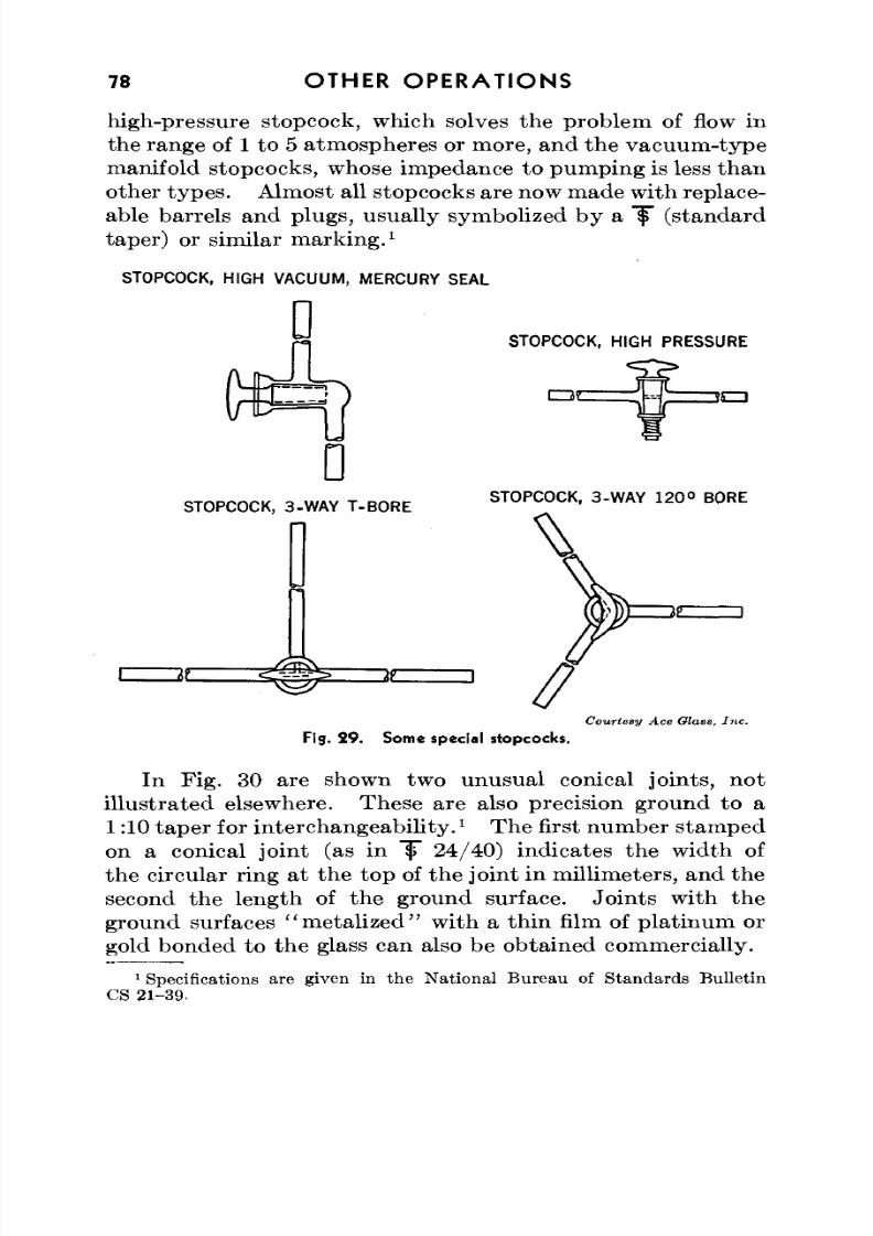
8/3/2019 Techniques of Glass Manipulation - Heldman
http://slidepdf.com/reader/full/techniques-of-glass-manipulation-heldman 90/144
78 OTHER OPERATIONS
high-pressure stopcock, which solves the problem of flow inthe range of 1 to 5 atmospheres or more, and the vacuum -type
manifold stopcocks, whose impedance to pum ping is less thanother types. Almost all stopcocks are now made with replace-able barrels and plugs, usually symbolized by a lp" (standardtaper) or similar marking.
1
STOPCOCK, HIGH VACUUM, MERCURY SEAL
STOPCOCK, HIGH PRESSURE
STOPCOCK, 3-WA Y T-B OR ESTOPCOCK, 3-W AY 1 2 0 ° BORE
I 61.
Courtesy Ace Glass, Inc.Fig. 2 9 . Som e special stopcocks.
In Fig. 30 are shown two unusual conical joints, notillustra ted elsewhere. These are also precision ground to a1:10 taper for interchangeability.
1The first num ber stamped
on a conical joint (as in "if" 24/40) indicates the width ofthe circular ring at the top of the joint in millimeters, and the
second the length of the ground surface. Jo ints with theground surfaces "metalized" with a thin film of platinum orgold bonded to the glass can also be obtained commercially.
1Specifications are given in the National Bureau of Standards Bulletin
CS 21-39,
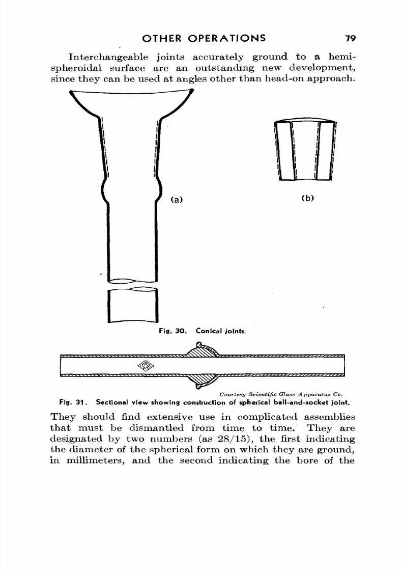
8/3/2019 Techniques of Glass Manipulation - Heldman
http://slidepdf.com/reader/full/techniques-of-glass-manipulation-heldman 91/144
OTHER OPERATIONS 79
Interchangeable joints accurately ground to a hemi-spheroidal surface are an outstanding new development,
since they can be used at angles other tha n head-on approach .
7
1
(a) (b)
Fig. 3 0 . Conical joints.
Courtesy Scientific G lass Apparatus Co.
Fig. 3 1 . Sectional view showing construction of spherical ball-an d-sock et joint.
They should find extensive use in complicated assembliesth at m ust be dismantled from time to time. They aredesignated by two numbers (as 28/15), the first indicatingthe diameter of the spherical form on which they are ground,in millimeters, and the second indicating the bore of the
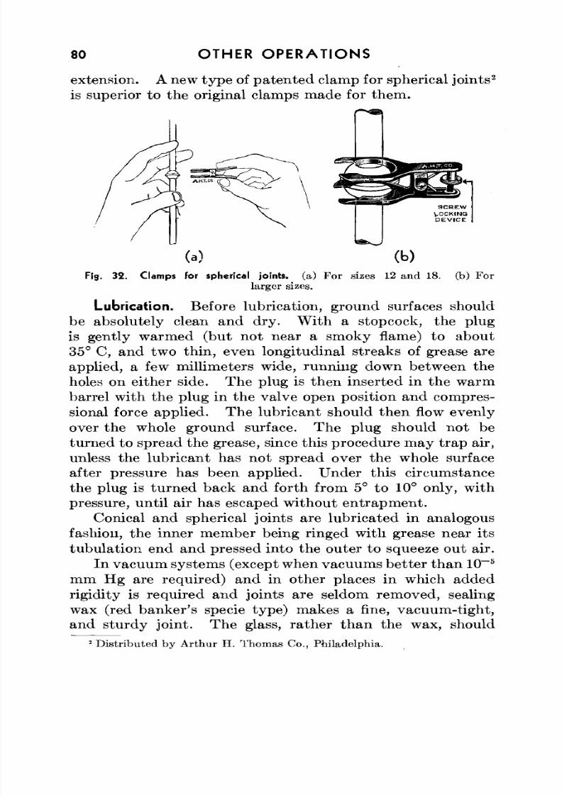
8/3/2019 Techniques of Glass Manipulation - Heldman
http://slidepdf.com/reader/full/techniques-of-glass-manipulation-heldman 92/144
80 OTHER OPERATIONS
extension. A new typ e of pa ten ted clamp for spherical join ts2
is superior to the original clamps made for them.
Fig. 32 . Clamps for spherical joints, (a) Fo r sizes 12 an d 18. (b) Fo rlarger sizes.
Lubrication. Before lubrication, ground surfaces shouldbe absolutely clean and dry. W ith a stopcock, the plugis gently warmed (but not near a smoky flame) to about35° C, and two thin, even longitudinal streaks of grease areapplied, a few millimeters wide, running down between theholes on either side. Th e plug is then inserted in the w armbarrel with the plug in the valve open position and compres-sional force applied. The lubrican t should then flow evenlyover the whole ground surface. Th e plug should not beturned to spread the grease, since this procedure may tr ap air,
unless the lubricant has not spread over the whole surfaceafter pressure has been applied. Under this circumstancethe plug is turned back and forth from 5° to 10° only, withpressure, until air has escaped without entrapment.
Conical and spherical joints are lubricated in analogousfashion, the inner member being ringed with grease near itstubulation end and pressed into the outer to squeeze out air.
In vacuu m systems (except when vacuum s be tter th an 10~5
mm Hg are required) and in other places in which addedrigidity is required and joints are seldom removed, sealingwax (red banker's specie type) makes a fine, vacuum-tight,and sturdy joint. The glass, rath er tha n the wax, should
2Distr ibuted by Arthur H. Thomas Co., Philadelphia.
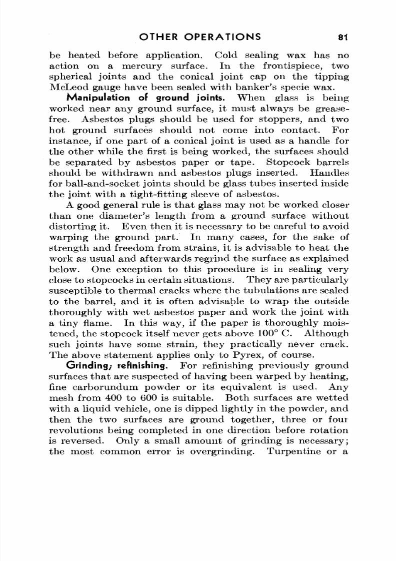
8/3/2019 Techniques of Glass Manipulation - Heldman
http://slidepdf.com/reader/full/techniques-of-glass-manipulation-heldman 93/144
OTHER OP ER ATIO NS 81
be heated before application . Cold sealing wax has noaction on a mercury surface. In the frontispiece, twospherical joints and the conical joint cap on the tippingMcLeod gauge have been sealed with banker's specie wax.
Manipulation of ground joints. W he n glass is being
worked near any ground surface, it must always be grease-free. Asbestos plugs should be used for stoppers, and twohot ground surfaces should no t come into con tact. Forinstance, if one part of a conical joint is used as a handle forthe other while the first is being worked, the surfaces should
be separated by asbestos paper or tap e. Stopcock barrelsshould be w ithdraw n and asbestos plugs inserted. Hand lesfor ball-and-socket joints should be glass tubes inserted insidethe joint with a tight-fitting sleeve of asbestos.
A good general rule is that glass may not be worked closerthan one diameter's length from a ground surface withoutdisto rting it. Even then it is necessary to be careful to avoidwarping the ground par t. In m any cases, for the sake of
strength and freedom from strains, it is advisable to heat thework as usual and afterwards regrind the surface as explainedbelow. One exception to this procedure is in sealing veryclose to stopcocks in certain situa tions. They are particu larlysusceptible to thermal cracks where the tubulations are sealedto the barrel, and it is often advisable to wrap the outsidethoroughly with wet asbestos paper and work the joint witha tiny flame. In this way , if the pap er is thorough ly mois-tened, the stopcock itself never gets above 100° C. Althoughsuch joints have some strain, they practically never crack.The above statement applies only to Pyrex, of course.
Grinding; refinishing. For refinishing previously groundsurfaces that are suspected of having been warped by heating,fine carborundum pow der or its equivalent is used. Anymesh from 400 to 600 is suitab le. Both surfaces are wetted
with a liquid vehicle, one is dipped lightly in the powder, andthen the two surfaces are ground together, three or fourrevolutions being completed in one direction before rotationis reversed. Only a small am ount of grinding is necessary;the most common error is overgrinding. Tu rpentine or a
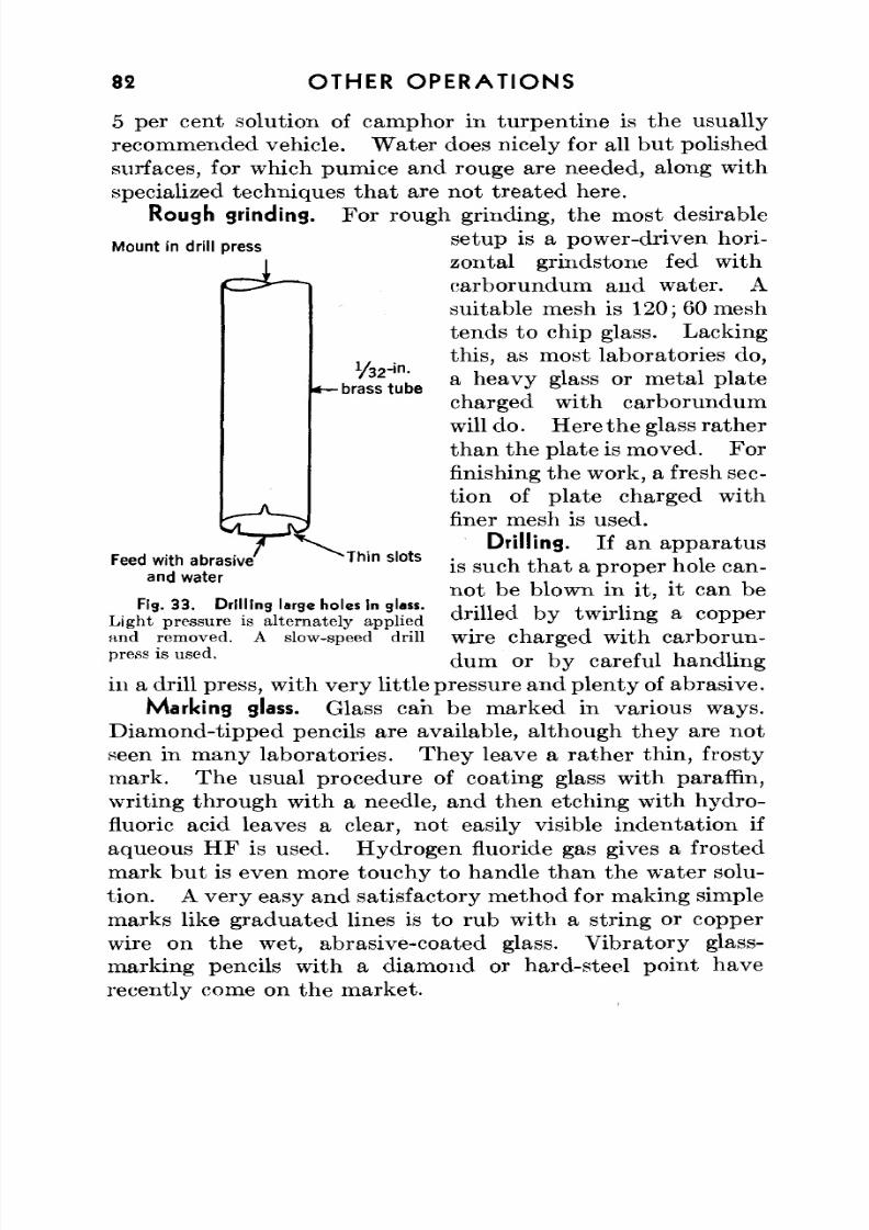
8/3/2019 Techniques of Glass Manipulation - Heldman
http://slidepdf.com/reader/full/techniques-of-glass-manipulation-heldman 94/144
82 OTHER OPERATIONS
Mount in drill press
5 per cent solution of camphor in turpentine is the usuallyrecommended vehicle. W ater does nicely for all bu t polishedsurfaces, for which pumice and rouge are needed, along withspecialized techniques that are not treated here.
Rough grinding. For rough grinding, the most desirablesetup is a power-driven hori-zontal grindstone fed withcarborundum and water. Asuitable mesh is 120; 60 meshtends to chip glass. Lacking
this, as most laboratories do,a heavy glass or metal platecharged with carborundumwill do . Here the glass rathe rtha n the plate is moved. Forfinishing the work, a fresh sec-tion of plate charged withfiner mesh is used.
Drilling. If an apparatusis such th a t a prop er hole can-not be blown in it, it can bedrilled by twirling a copper
1/32-in.
-brass tube
Feed with abrasiveand water
Thin slots
Fig. 3 3 . Drillin g large holes in glass.
Light pressure is alternately appliedand removed. A slow-speed drillpress is used.
wire charged with carborun-dum or by careful handling
in a drill press, w ith very little pressure and p len ty of abrasive.
Marking glass. Glass can be marked in various ways.Diamond-tipped pencils are available, although they are notseen in m any laboratories. Th ey leave a rath er thin, frostymark. Th e usual procedure of coating glass w ith paraffin,writing through with a needle, and then etching with hydro-fluoric acid leaves a clear, n ot easily visible inden tation ifaqueous H F is used. Hydro gen fluoride gas gives a frostedmark but is even more touchy to handle than the water solu-
tion. A very easy and satisfactory method for making simplemarks like graduated lines is to rub with a string or copperwire on the wet, abrasive-coated glass. V ibra tory glass-marking pencils with a diamond or hard-steel point haverecently come on the market.
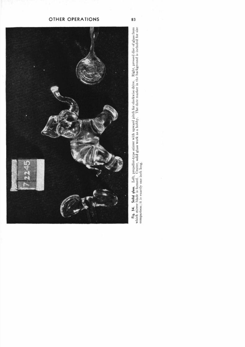
8/3/2019 Techniques of Glass Manipulation - Heldman
http://slidepdf.com/reader/full/techniques-of-glass-manipulation-heldman 95/144
mTO m 73 o z to
Fg3SdgaL
po
e
y
s
e
w
huw
d
p
c
fo
co
ws
d
v
Rg
pe
ds
oga
fom
w
c
s
e
ba
sfom
C
e
sodga
w
ka
ah
T
d
em
k
n
h
b
o
sn
u
fo
sz
cm
so
se
yo
n
o
8/3/2019 Techniques of Glass Manipulation - Heldman
http://slidepdf.com/reader/full/techniques-of-glass-manipulation-heldman 96/144
84 OTHER OP ER AT IONS
Solid glass. Solid glass cannot be blown, of course, but isworked by pushing and pulling, or squeezing between carbonpaddles or forceps. Big lumps of solid glass will require care-ful annealing. In addition to being made into utilita rianobjects such as stirrers, solid glass can be fashioned into"sculptured" forms like statues, and thus offers itself as amedium for an interesting hobby.
Stirrers. To m ake a stirrer, th e end of a glass rod is rota tedin the flame un til a spherical lump forms. I t is at once pressedbetween carbon plate s un til it has flattened into a disc. The
junction of the disc and rod handle is heated, and the formeris grasped with a forceps and pulled until only a thin con-nection remains. Two such discs, still connected to theirhandles, are m ade. These discs are attached to a small globeof glass on the tip of the stirrer shaft, both parts of each weldbeing heated before joining. The handles are pulled off andthe blades fashioned by squeezing, pushing, and pulling off hotglass. Any shape and pitch can be made. Lum py joins are
smoothed by intense local heat, since really hot glass flowslike honey to form a smooth surface. Very large stirrerblades can be made if a glass saw is ava ilable. A ring of40-mm tubing, about 20 mm wide, is cut off and then cut toform two half circles, one of which is turned about and sealedto the other to form a large curved blade.
Vitreous silica. Silica glass3
is used in cases in which very
high temperatures are encountered or special chemical inert-ness is required, and in photochemical applications in whichtransm ission of ultraviole t light is desired. Silica glass intransparent form can be purchased for photochemical work orin a translucent or satin-like opaque form for the first twogeneral uses given above.
Silica softens only at very high temperatures and has avery small working range. In consequence it is necessary to
use an oxy-hydrogen flame for tubing*of 7-mm o.d. and larger,3
Referring to fused or vitreo us silica as " q u a r t z " is a comm on error. Silicais the name given to the chemical, silicon dioxide (SiO 2), which in any form canbe made into a glass, whereas quartz is a crystalline form of silica, the propertiesof which are distinc tly different from the vitreous form. Silica glass cann ot besealed directly to qiiartz, which shatters on sudden heating.
8/3/2019 Techniques of Glass Manipulation - Heldman
http://slidepdf.com/reader/full/techniques-of-glass-manipulation-heldman 97/144
OTHER OP ER AT ION S 85
and usually to blow while the heated spot is in the flame.Offsetting these disadvantages are the facts that silica has an
extremely low expansion coefficient and hence requires noannealing, and that it is harder and mechanically strongerthan any other glass.
The blinding white light of hot silica makes it necessary touse dark goggles when working it, and the intense heat mayrequire a special mask for shielding the face.
Vycor. Recently a new g la ss ,' ' Vycor " (Corning Nos. 790and 792), has appeared on the m ark et. M ade from an ordi-
nary type of glass by a special process that leaches out themajority of metals present, Vycor contains approximately96 per cent silica and has properties approaching those of thepure fused chemical. I t can be advantageously employedin many cases as a substitute for the more expensive silica,which is difficult to manufacture.
Seals. Silica seals are almost invariably made by thespot-heating technique, unless lathe facilities are at hand.Using the hand torch, one clamps the larger piece in place,welds on one spot of the smaller piece, and finishes the sealwith use of silica welding rod as necessary . After a smallportion of the periph ery has fused together and cooled slightly,it is not necessary to brace the smaller piece, since the weldedspot will not become hot enough to flow again without direct,intense heat.
The seal can be smoothed somewhat by blowing. Silicashould be blown while it is in the flame, with very gentlepuffs, owing to its high, short working rang e. If blown toohard, it will blow ou t. However, if this occurs, it is onlynecessary to patch the hole with welding rod, a repair that ismuch easier with silica than with Pyrex.
Bends. It is impossible to bend silica by the techniquesused for soft glass or Py rex . A small section of the periphery
is heated and bent slightly, another section heated and bent,and so on. K inks and flat spots are the n smoothed as wellas possible by spot hea ting. I t is obvious th a t the concaveside will be thick and lumpy and the convex side thin andflattened. However, owing to th e low coefficient of expansion
8/3/2019 Techniques of Glass Manipulation - Heldman
http://slidepdf.com/reader/full/techniques-of-glass-manipulation-heldman 98/144
86 OTHER OPE RA TIONS
and the great mechanical strength of silica, neither of thesedefects, which would be serious with soft glass or even Pyrex,
detracts from the usefulness of a silica bend.Graded seals. For fusing silica to Pyrex N o. 774, a gradedseal is necessary. W hile serviceable graded seals can be madeat the glass bench, it is preferable to use the tes ted commercialarticle. Ev en though they are expensive, so few are neededand they are so superior to the homemade kind that it iscertainly advisable to employ them.
In the laboratory, graded seals are made by sealing in
order, starting at the silica end, silica, Corning glasses 790,723, 720, 724, and 774. The 720-724 seal is hardest to workbecause 720 softens 300° higher than 724, but it may not beas strained as the 724-774 seal, in which the difference inexpansion coefficients is grea tes t. In an emergency, gradedseals can be made by fusing together batches of ground-upsilica and 774 in the proportions 4 : 1 , 3 :1 , 2 :1 , 1:1, 1:2, 1:3,and 1:4, stirring the melts for thorough mixing, drawing themout into welding rod, and applying successive rings of themixtures in order on a silica tube of the desired diameter.One can also add enough of each batch to close off the end,blow it out into a kidney, trim the edge, and apply the nextglass. Th is metho d allows the different m ixtures to flowtogether better than in the technique of adding rings.
Simple breaks in graded seals can be repaired by careful
manipulation, especially if the broken ends fit together well.The Pyrex No. 774 portion should be held below the silicaend, since he at conduction in air is upw ards. Otherwise the774 part will soften and flow before the silica end is hot enoughto work.
Devitrification. Owing to the crystallization of silica onrapid cooling, a cloudy area is often observed after heating,especially at the edges of the worked po rtion . Th is cloudiness
is almost always a surface phenomenon and does no harmexcept in cases in which light transmission is important.Rinsing the area w ith a hydrofluoric acid solution will usuallyclear up the milkiness.
8/3/2019 Techniques of Glass Manipulation - Heldman
http://slidepdf.com/reader/full/techniques-of-glass-manipulation-heldman 99/144
CHAPTER X
Glass-to-Metal Seals
T H E direct joining of glass to various m etals involves man ip-• ulations that are no more difficult than those required in
making a T seal or perhap s a simple ring seal; yet th e principleswhich must be followed are in general so poorly recognizedby laboratory technicians that such seals are a common
stumbling block to many otherwise proficient glass blowers.General principles; glass must wet metal. To make a suc-
cessful glass-to-metal seal, it is necessary to insure that theglass will bond to the metal—that is, that the hot, plasticglass will wet, flow into, and form an adhesive union with themetal surface. Th is requ irem ent always makes it necessaryto de-gas the metal, since all metals adsorb large amounts ofgases on the ir surfaces. The adsorbed gases, if not previously"boiled," off, will vaporize while the seal is being worked andgive rise to bubbles at the interface, which will be imperfectlybonded, strained, and may have capillary leak paths.
The oxide film. Although some controversy still arisesover the point, it is generally conceded that glasses do notbond to metals at a surface but rather to their oxides, thepossible exception being pla tinum . I t is therefore necessary
to oxidize a metal surface before sealing to glass (with plati-num, which forms a surface oxide only under specializedconditions, this is questionable). On the other han d, sincemetals are not usually isomorphous with their oxides, a thickoxide coat may lead to a porous, brittle, and mechanicallyweak seal. The proper degree of oxidation is a critical factorin making glass-to-metal seals with desired properties.
Thermal expansion. As pointed out in Chapter I, the
expansion coefficients of glasses rise markedly as they areheated. Ev en if a glass and a metallic element have the samethermal expansion coefficient at relatively low temperatures,their seal will still be somewhat strained because their expan-
87
8/3/2019 Techniques of Glass Manipulation - Heldman
http://slidepdf.com/reader/full/techniques-of-glass-manipulation-heldman 100/144
88 G L A S S - T O - M E T A L S E AL S
sion characteristics will be different at working temperatures.Only with the K ova r and Fernico alloys, the expansion charac-
teristics of which were successfully engineered to resemblethose of glasses, is an unstrained glass-to-metal seal possible.Two types of seals with metallic elements will nonethelesswork. The first is one in which the expansion coefficients ofthe given glass and metal are close enough so that the seal,though strained, is mechanically strong enough to resist thebreaking forces set up upon cooling. The second type , inwhich materials with quite different expansion coefficients are
sealed, depends upon the use of a very thin piece of metal,preferably with a low yield point, so that the large coolingstrains are relieved by the deformation of the metal ratherthan th e cracking of the glass. Th is type of seal is possiblepractically only with metals that are ductile and malleableat room temperature.
W ith the foregoing in mind, the actual manipulations inmaking glass-to-metal seals described in the following dis-cussion should be considered in terms of the principles under-lying them as well as the empirical experience that has shownthem to be workable procedures.
Platinum. The coefficients of expansion of platinum andsome soft glasses at low temperatu res are practica lly identical,and vacuum -tight seals between them may be made with littlestrain. Lead glass appears to wet the m etal be tter tha n lime
glass and should be used if possible.The wire is first heated orange-red at the spot at which theseal is to be made to de-gas the surface as much as possible.It should be remembered that metals are good heat con-ductors, so that the platinum should be handled with a pinvise, forceps, or a handle of thin cane to which the platinumhas been sealed at a low temp eratu re so th at the rod can laterbe cracked away cleanly. Platin um m elts at a relatively
low temperature and should never directly receive the fullheat of the torch more th an mom entarily. Pla tinu m doesnot oxidize appreciably, and no unusual precautions needbe taken to insure a clean metal surface other than the firstheating.
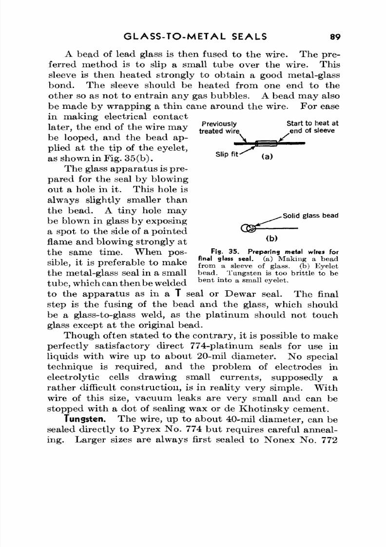
8/3/2019 Techniques of Glass Manipulation - Heldman
http://slidepdf.com/reader/full/techniques-of-glass-manipulation-heldman 101/144
G L AS S-TO -ME TA L SEALS 89
A bead of lead glass is the n fused to the wire. Th e pre -ferred method is to slip a small tube over the wire. Th is
sleeve is then heated strongly to obtain a good metal-glassbond. The sleeve should be hea ted from one end to theother so as not to entra in any gas bubbles. A bead may alsobe made by wrapping a thin cane around th e wire. For easein making electrical contactIn te r t h p e n d of t h e w ir e m n v Previously Start to heat at
l a t e r , t n e e n a 01 t n e w i r e m a y t r e a t e d w i r e e n d Of S | e e v e
be looped, and the bead ap- \ f
plied at the tip of the eyelet, " ^ r * ^
5
^ ^ ^ ^as shown in Fig. 35(b ).Slip fit
<a)The glass ap pa ratu s is pre-
pared for the seal by blowingout a hole in it. This hole isalways slightly smaller thanthe bead. A tiny hole may . , ,_ .. . . , , . ^ Solid glass bead
be blown in glass by exposing r^c^^^"^a spot to the side of a pointed ^ ^flame and blowing strongly at * 't h e s a m e t i m e . W h e n DOS- Fig. 35. Preparing metal wires forible, it is preferable to make ttJlV^ ^ tt h e m et al -g la S S Seal in a Sm all bead. Tungsten is too brittle to be
tub e, which can then be weldedb en t in to a sma11 e
yelet
-to the app ara tus as in a T seal or Dewar seal. The finalstep is the fusing of the bead and the glass, which should
be a glass-to-glass weld, as the platinum should not touchglass except at the original bead.
Though often stated to the co ntrary, it is possible to m akeperfectly satisfactory direct 774-platinum seals for use inliquids with wire up to about 20-mil diameter". No specialtechnique is required, and the problem of electrodes inelectrolytic cells drawing small currents, supposedly arathe r difficult construction, is in reality very simple. W ith
wire of this size, vacuum leaks are very small and can bestopped with a dot of sealing wax or de Khotinsky cement.
Tungsten. The wire, up to about 40-mil diameter, can besealed directly to Pyrex No. 774 but requires careful anneal-ing. Larger sizes are always first sealed to N onex No. 772
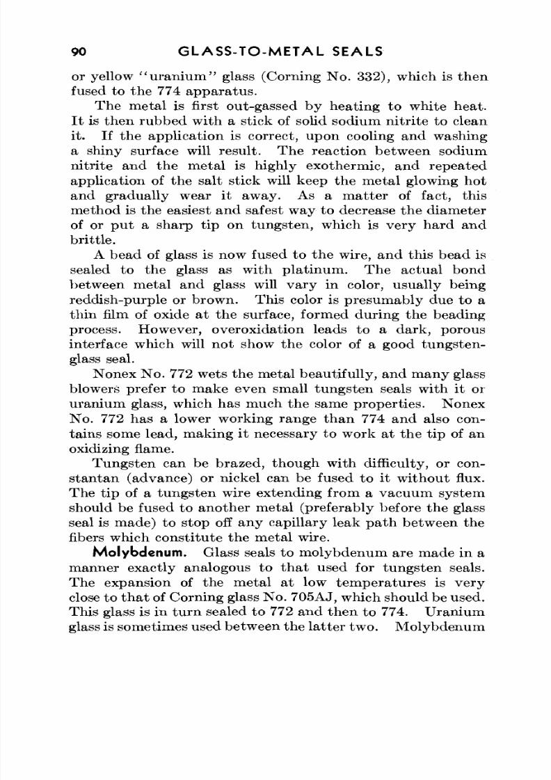
8/3/2019 Techniques of Glass Manipulation - Heldman
http://slidepdf.com/reader/full/techniques-of-glass-manipulation-heldman 102/144
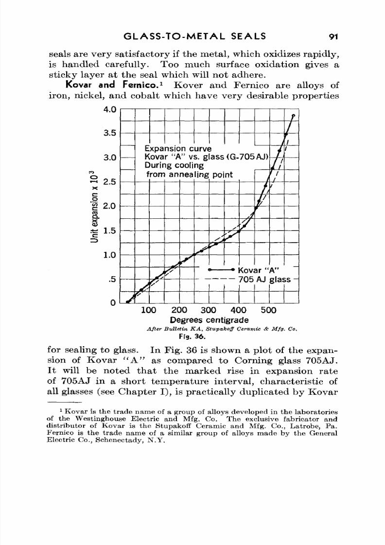
8/3/2019 Techniques of Glass Manipulation - Heldman
http://slidepdf.com/reader/full/techniques-of-glass-manipulation-heldman 103/144
GLASS-TO-METAL SEALS 91
seals are very satisfactory if the m etal, w hich oxidizes rapidly,is handled carefully. Too much surface oxidation gives a
sticky layer at the seal which will not adhere.Kovar and Fernico.1
Kover and Fernico are alloys of
iron, nickel, and cobalt which have very desirable properties
4.0
3.5
3.0
toO
2.5
o
"I 2.0
a
I 1.51.0
.5
Expansion curve
Kovar "A" vs. glass (G-During cooling
from annealing point
V
y
705 AJ)
[A
i
/
1/
1f.I"/Ii
;
/
/
' • Kovar "A"
100 200 300 400
Degrees centigrade
500
Alter Bulletin KA, Stupakoff Ceramic & Mfg. Co.
Fig. 36.
for sealing to glass. In Fig. 36 is shown a plot of the expan-sion of Kovar "A" as compared to Corning glass 705AJ.It will be noted that the marked rise in expansion rateof 705AJ in a short temperature interval, characteristic of
all glasses (see Chapter I), is practically duplicated by Kovar
1Kovar is the t rade name of a group of alloys developed in the laboratories
of the W estinghouse Electric and Mfg. Co. The exclusive fabricator anddistributor of Kovar is the Stupakoff Ceramic and Mfg. Co., Latrobe, Pa.Fernico is the t rade name of a similar group of alloys made by the GeneralElectric Co., Schenectady, N.Y,
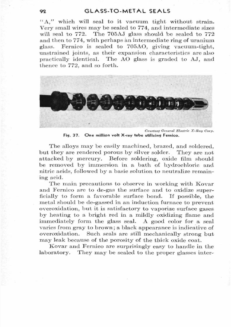
8/3/2019 Techniques of Glass Manipulation - Heldman
http://slidepdf.com/reader/full/techniques-of-glass-manipulation-heldman 104/144
92 G L AS S-TO -ME TA L SEALS
" A , " which will seal to it vacuum tight without strain.Very small wires may be sealed to 774, and inte rm ediate sizeswill seal to 772. The 705AJ glass should be sealed to 772and then to 774, with perhaps an interm ediate ring of uran ium
glass. Fernico is sealed to 705AO, giving vacuum-tight,unstrained joints, as their expansion characteristics are alsopractically identical. The AO glass is graded to AJ, andthence to 772, and so forth.
Courtesy General Electric X-Ray Corp.
Fig. 37 . O ne million volt X-ray tube utilizing Fernico.
The alloys may be easily machined, brazed, and soldered,bu t they are rendered porous by silver solder. They are notattacked by mercury. Before soldering, oxide film shouldbe removed by immersion in a bath of hydrochloric andnitric acids, followed by a basic solution to neutralize remain-ing acid.
The main precautions to observe in working with Kovar
and Fernico are to de-gas the surface and to oxidize super-ficially to form a favorable surface bond . If possible, themetal should be de-gassed in an induction furnace to preventoveroxidation, but it is satisfactory to vaporize surface gasesby heating to a bright red in a mildly oxidizing flame andimmediately form the glass seal. A good color for a sealvaries from gray to brow n; a black ap pearance is indicative ofoveroxidation. Such seals are still mechanically strong b utmay leak because of the porosity of the thick oxide coat.
Kovar and Fernico are surprisingly easy to handle in thelaboratory . They m ay be sealed to the proper glasses inter-
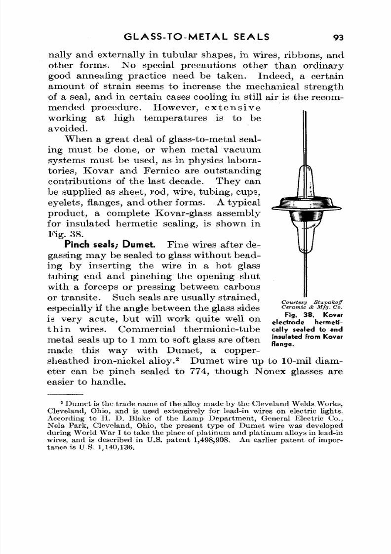
8/3/2019 Techniques of Glass Manipulation - Heldman
http://slidepdf.com/reader/full/techniques-of-glass-manipulation-heldman 105/144
GLASS-TO-METAL SEALS 93
nally and externally in tubular shapes, in wires, ribbons, andother forms. No special precautions other than ordinary
good annealing practice need be tak en . Indeed, a certainamount of strain seems to increase the mechanical strengthof a seal, and in certain cases cooling in still air is the recom-mended procedure. However, e x t e n s i v eworking at high temperatures is to beavoided.
W hen a great deal of glass-to-metal seal-ing must be done, or when metal vacuum
systems must be used, as in physics labora-tories, Kovar and Fernico are outstandingcontributions of the last decade. Th ey canbe supplied as sheet, rod, wire, tubing, cups,eyelets, flanges, and other forms. A typicalproduct, a complete Kovar-glass assemblyfor insulated hermetic sealing, is shown inFig. 38.
Pinch seals; Dumet. Fine wires after de-gassing may be sealed to glass w ithou t bead-ing by inserting the wire in a hot glasstubing end and pinching the opening shutwith a forceps or pressing between carbonsor trans ite. Such seals are usually strained ,especially if the angle between the glass sidesis very acute, but will work quite well onthin wires. Commercial thermionic-tubemetal seals up to 1 mm to soft glass are oftenmade this way with Dumet, a copper-sheathed iron-nickel alloy.
2Dumet wire up to 10-mil diam-
eter can be pinch sealed to 774, though Nonex glasses areeasier to handle.
Courtesy StupakoffCeramic & Mfg. Co.
Fig. 38. Kovar
electrode hermeti-cally sealed to and
insulated from Kovar
flange.
2 Du m et is the trad e nam e of the al loy made by the Cleveland W elds W orks,Cleveland, Ohio, and is used extensively for lead-in wires on electric lights.According to H. D. Blake of the Lamp Department, General Electric Co.,Nela Park, Cleveland, Ohio, the present type of Dumet wire was developedduring W orld W ar I to take the place of platinu m and p latinum alloys in lead-inwires, and is described in U.S. p ate nt 1,498,908. An earlier pa ten t of imp or-tance is U.S. 1,140,136.
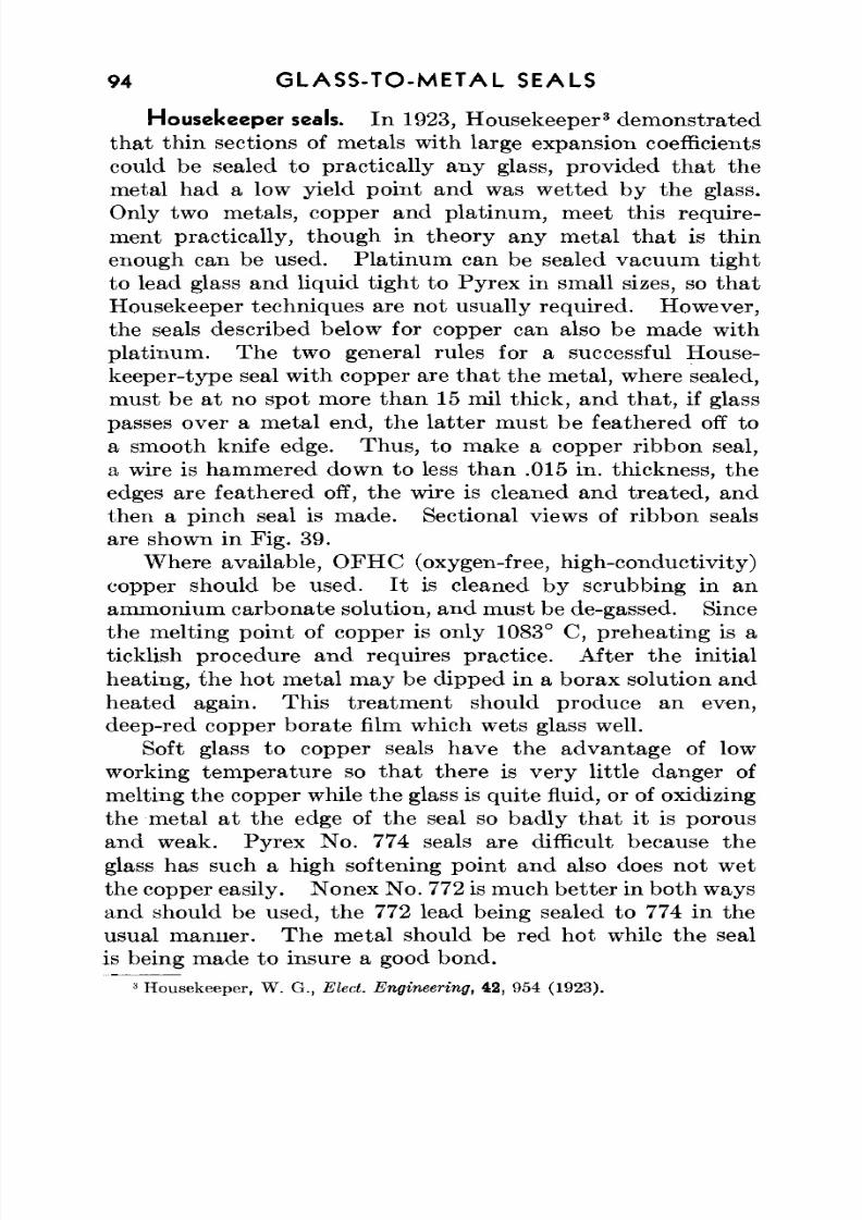
8/3/2019 Techniques of Glass Manipulation - Heldman
http://slidepdf.com/reader/full/techniques-of-glass-manipulation-heldman 106/144
94 GLA SS-TO -ME TAL SEALS
Housekeeper seals. In 1923, Housekeeper3
demonstratedthat thin sections of metals with large expansion coefficientscould be sealed to practically any glass, provided that themetal had a low yield point and was wetted by the glass.Only two metals, copper and platinum, meet this require-ment practically, though in theory any metal that is thinenough can be used. Platinu m can be sealed vacuum tig htto lead glass and liquid tight to Pyrex in small sizes, so thatHousekeeper techniques are not usually required. How ever,the seals described below for copper can also be made with
pla tinum . The two general rules for a successful H ouse-keeper-type seal w ith copper are th a t the m etal, where sealed,must be at no spot more than 15 mil thick, and that, if glasspasses over a metal end, the latter must be feathered off toa smooth knife edge. Thu s, to make a copper ribbon seal,a wire is hammered down to less than .015 in. thickness, theedges are feathered off, the wire is cleaned and treated, andthen a pinch seal is made. Sectional views of ribbon seals
are shown in Fig. 39.W here available, O FH C (oxygen-free, high-conductivity)
copper should be used. It is cleaned by scrubbing in anamm onium carbonate solution, and must be de-gassed. Sincethe melting point of copper is only 1083° C, preheating is aticklish procedure and requires practice. After the initialheating, the hot metal may be dipped in a borax solution and
heated again. Th is trea tm en t should produce an even,deep-red copper borate film which wets glass well.
Soft glass to copper seals have the advantage of lowworking temperature so that there is very little danger ofmelting th e copper while the glass is qu ite fluid, or of oxidizingthe metal at the edge of the seal so badly that it is porousand weak. Py rex N o. 774 seals are difficult because theglass has such a high softening point and also does not wet
the copper easily. Nonex N o. 772 is much better in bo th waysand should be used, the 772 lead being sealed to 774 in theusual m anner. Th e m etal should be red ho t while the sealis being made to insure a good bond.
3Housekeeper, W. G., Elect. Engineering, 42, 954 (1923).
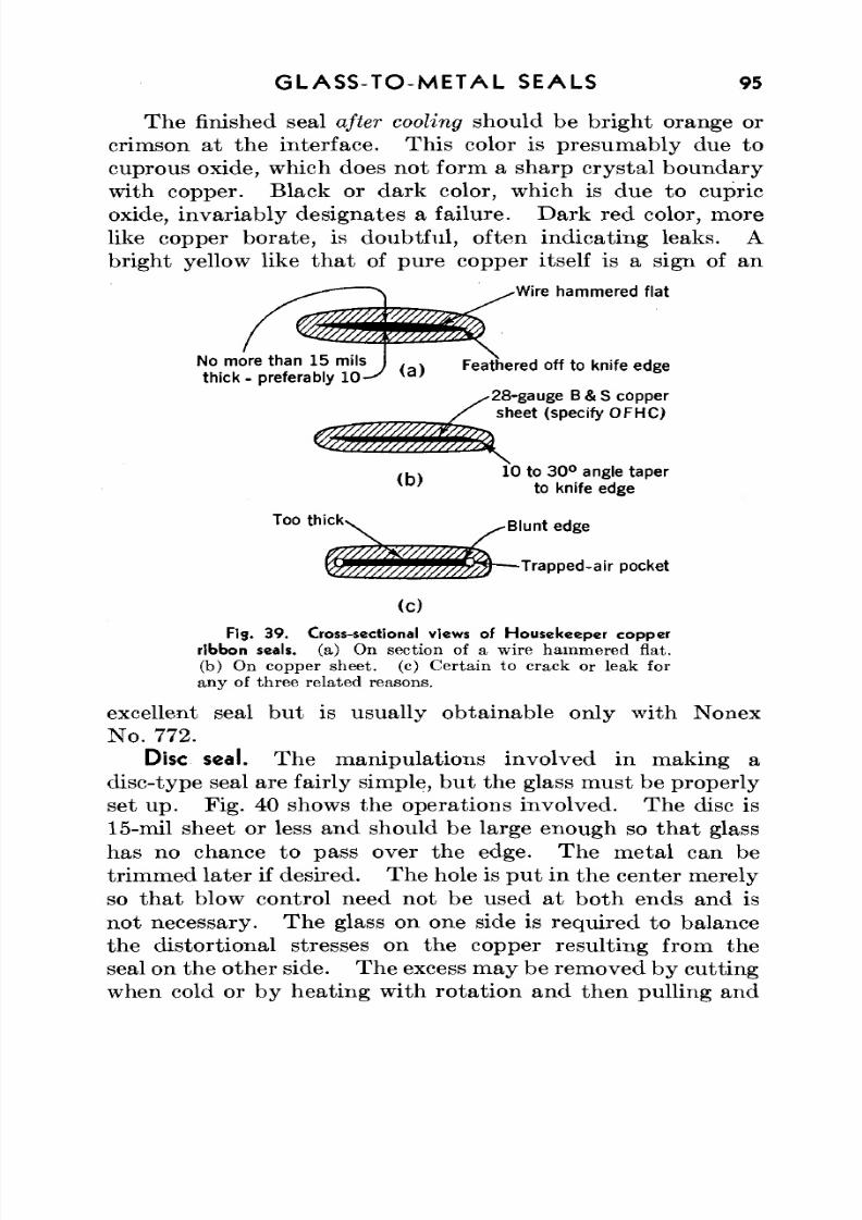
8/3/2019 Techniques of Glass Manipulation - Heldman
http://slidepdf.com/reader/full/techniques-of-glass-manipulation-heldman 107/144
GLASS-TO-METAL SEALS 95
The finished seal after cooling should be bright orange or
crimson at the interface. Th is color is presumably due to
cuprous oxide, which does not form a sharp crystal boundarywith copper. Black or dark color, which is due to cupricoxide, invariably designates a failure. Dark red color, morelike copper borate, is doubtful, often indicating leaks. A
bright yellow like that of pure copper itself is a sign of an
^Wire hammered flat
No more than 15 mils . . ,
thick - preferably 1 0 ^{a)
Feathered off to knife edge
28-gauge B & Scopper
sheet (specify OFHC)
10 to 30°angle taperto knife edge
Too th ickv. Blunt edge
p °c k e t
(c)Fig. 39. Cross-sectional views of Housekeeper copper
ribbon seals, (a) On section of a wire hammered flat,
(b) On copper sheet, (c) Certain to crack or leak for
any of three related reasons.
excellent seal but is usually obtainable only with NonexNo. 772.
Disc seal. The manipulations involved in making a
disc-type seal are fairly simple, but the glass must be properlyset up. Fig. 40 shows the operations involved. The disc is
15-mil sheet or less and should be large enough so that glasshas no chance to pass over the edge. The metal can be
trimmed later if desired. Thehole is put in the center merelyso that blow control need not be used at both ends and is
not necessary. The glass on one side is required to balancethe distortional stresses on the copper resulting from the
seal on the other side. Theexcess may be removed by cuttingwhen cold or by heating with rotation and then pulling and
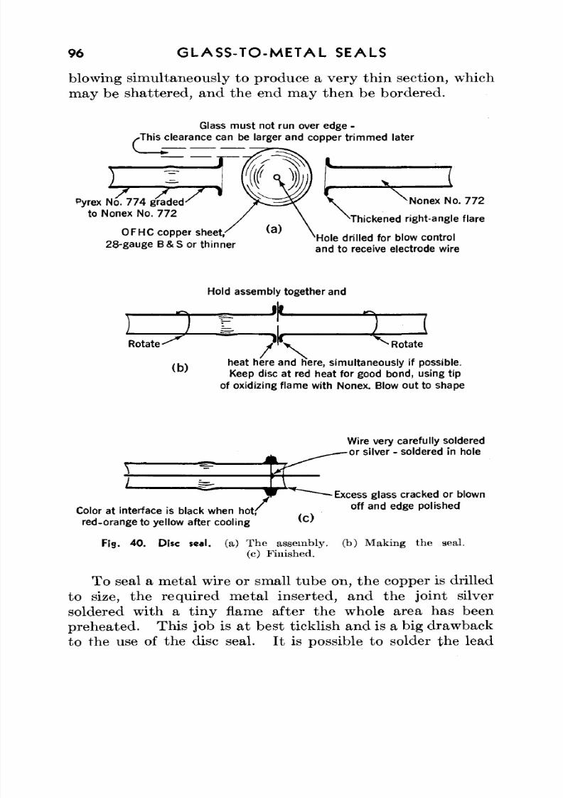
8/3/2019 Techniques of Glass Manipulation - Heldman
http://slidepdf.com/reader/full/techniques-of-glass-manipulation-heldman 108/144
96 GLASS-TO-METAL SEALS
blowing simultaneously to produce a very thin section, whichmay be shattered, and the end may then be bordered.
Glass must not run over edge -/This clearance can be larger and copper trimmed later
Pyrex No. 774 gr ad ed 'to Nonex No. 772
OFHC copper sheet,-28-gauge B & S or thinner
^ N o n e x N o. 7 72
'Thickened right-angle flare
xHole drilled for blow controland to receive electrode wire
Hold assembly together and
J F
Rotate ^
(b)
Rotateheat here and here, simultaneously if possible.Keep disc at red heat for good bond, using tip
of oxidizing flame with Nonex. Blow out to shape
Color at interface is black when hot,'red-orange to yellow after cooling
Fig. 40. Disc seal. (a) T he assembly,(c) Finished.
Wire very carefully solderedor silver - soldered in hole
Excess glass cracked or blownoff and edge polished
(b) Making the seal.
To seal a metal wire or small tube on, th e copper is drilledto size, the required metal inserted, and the joint silversoldered with a tiny flame after the whole area has beenpreh eated . Th is job is at best ticklish and is a big drawbackto the use of the disc seal. I t is possible to solder the lead
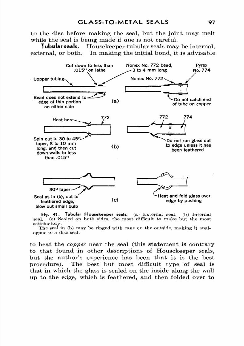
8/3/2019 Techniques of Glass Manipulation - Heldman
http://slidepdf.com/reader/full/techniques-of-glass-manipulation-heldman 109/144
GLASS-TO-METAL SEALS 97
to the disc before making the seal, but the joint may meltwhile the seal is being m ade if one is not careful.
Tubular seals. Housekeeper tubular seals may be internal,external, or both. In making the initial bond, it is advisable
Cut down to less than. 015 " on lathe
Copper tubin g N
Bead does not extend to-==— - ^edge of thin portion
on either side
Nonex No. 772bead,3 to 4 mm long
Nonex No. 772
Pyrex
No. 774
Heat here-
Spin out to 30 to 45°-
taper, 8 to 10 mm
long, and then cut
down walls to lessthan .015"
(a) Do not catch endof tube oncopper
772
(b)Do not runglass out
to edge unless it has
been feathered
Seal as in (b), out to
feathered edge;blow outsmall bulb
(0
and fold glass over
edge by pushing
Fig. 41. Tubular Housekeeper seals, (a) E x t e rn a l seal, (b) I n t e rn a lseal, (c) Sealed on both sides, the most difficult to make but the most
satisfactory.
The seal in (b) may be ringed with cane on the outside, making it anal-
ogous to a disc seal.
to heat the copper near the seal (this statement is contrary
to that found in other descriptions of Housekeeper seals,but the author's experience has been that it is the bestprocedure). The best but most difficult type of seal is
that in which the glass is sealed on the inside along the wallup to the edge, which is feathered, and then folded over to
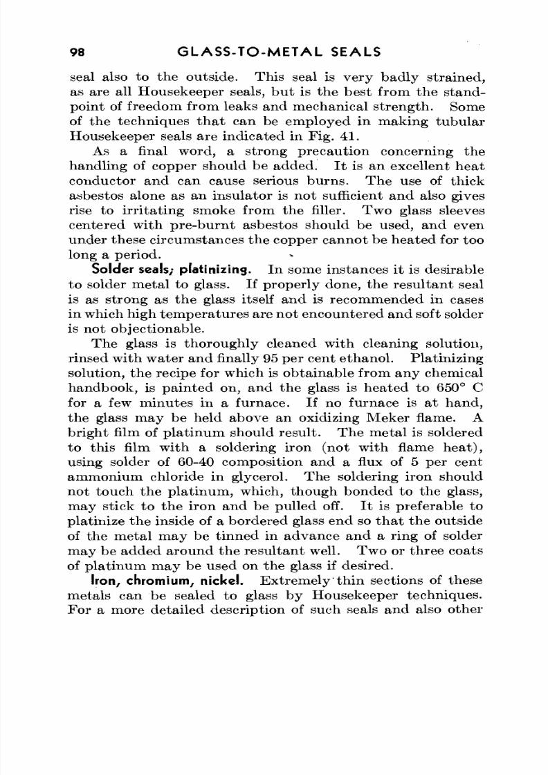
8/3/2019 Techniques of Glass Manipulation - Heldman
http://slidepdf.com/reader/full/techniques-of-glass-manipulation-heldman 110/144
98 GL AS S-TO -ME TA L SEALS
seal also to the outside. Th is seal is ve ry bad ly strained ,as are all Housekeeper seals, but is the best from the stand-
poin t of freedom from leaks and mechanical streng th. Someof the techniques that can be employed in making tubularHousekeeper seals are indicated in Fig. 41.
As a final word, a strong precaution concerning thehand ling of copper should be add ed. I t is an excellent heatconductor and can cause serious bu rns. The use of thickasbestos alone as an insulator is not sufficient and also givesrise to irritating smoke from the filler. Two glass sleeves
centered with pre-burnt asbestos should be used, and evenunder these circumstances the copper cannot be hea ted for toolong a period.
Solder seals; platinizing. In some instances it is desirableto solder m etal to glass. If properly done, the resu ltan t sealis as strong as the glass itself and is recommended in casesin which high tem peratu res are not encountered and soft solderis not objectionable.
The glass is thoroughly cleaned with cleaning solution,rinsed w ith water and finally 95 per cent etha no l. Platinizingsolution, the recipe for which is obtainable from any chemicalhandbook, is painted on, and the glass is heated to 650° Cfor a few m inutes in a furnace. If no furnace is at han d,the glass may be held above an oxidizing Meker flame. Abrigh t film of platin um should resu lt. Th e m etal is soldered
to this film with a soldering iron (not with flame heat),using solder of 60-40 composition and a flux of 5 per centammonium chloride in glycerol. The soldering iron shouldnot touch the platinum, which, though bonded to the glass,may stick to the iron and be pulled off. I t is preferable toplatinize the inside of a bordered glass end so that the outsideof the metal may be tinned in advance and a ring of solderm ay be added aroun d the resu ltant well. Two or three coats
of platinum may be used on the glass if desired.Iron, chromium, nickel. Extremely'thin sections of these
metals can be sealed to glass by Housekeeper techniques.For a more detailed description of such seals and also other

8/3/2019 Techniques of Glass Manipulation - Heldman
http://slidepdf.com/reader/full/techniques-of-glass-manipulation-heldman 111/144
G LA SS -TO -M ETA L SEALS 99
aspects of glass-to-metal seals, the reader should consultHousekeeper and others.
4
Porcelain. Electrical porcelain can be sealed to glass if theexpansion coefficients are closely m atched. The techniquesare similar to Kovar seals.
6
4Housekeeper, W. G., Elect. Engineering, 42, 954 (1923); Hull, A. W., and
Burger, E. E., Physics, 5, 384 (1934); Hull, A. W., Burger, E. E., and Navias, L.,J. App. Physics, 12, 698 (1941).
5Bahls , W. E . , Elect. Engineering, 57, 373 (1938).
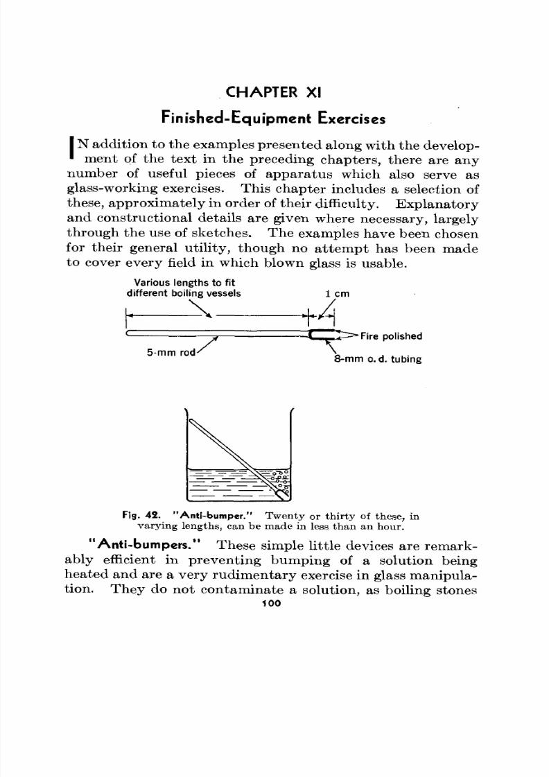
8/3/2019 Techniques of Glass Manipulation - Heldman
http://slidepdf.com/reader/full/techniques-of-glass-manipulation-heldman 112/144
CHAPTER XI
Finished-Equipment Exercises
IN addition to the examples presented along with the develop-' ment of the text in the preceding cha pters, there are anynumber of useful pieces of apparatus which also serve asglass-working exercises. This ch ap ter includes a selection ofthese, approxim ately in order of their difficulty. Ex planatoryand constructional details are given where necessary, largelythrough the use of sketches. The examples have been chosenfor their general utility, though no attempt has been madeto cover every field in which blown glass is usable.
Various lengths to fitdifferent boiling vessels
\ _
1 cmA5-mm rod' X
•Fire polished
8-mm o. d. tubing
F13. 42. "Anti-bumper." Twenty or thirty of these, invarying lengths, can be made in less than an hour.
"Anti-bumpers." These simple little devices are remark-ably efficient in preventing bumping of a solution beingheated and are a very rud im en tary exercise in glass manipula-tion. They do not con taminate a solution, as boiling stones
100
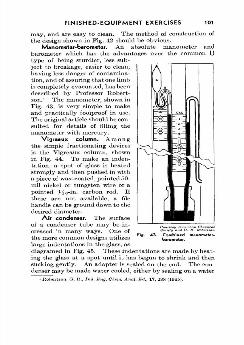
8/3/2019 Techniques of Glass Manipulation - Heldman
http://slidepdf.com/reader/full/techniques-of-glass-manipulation-heldman 113/144
FINISHED-EQUIPMENT EXERCISES 101
may, and are easy to clean. Th e m ethod of construction ofthe design shown in Fig. 42 should be obvious.
Manometer-barometer. An absolute manometer andbarometer which has the advantages over the common Utype of being sturdier, less sub-ject to breakage, easier to clean,having less danger of contamina-tion, and of assuring th a t one limbis completely evacu ated, has beendescribed by Professor Robert-
son.x
The manometer, shown inFig. 43, is very simple to makeand practically foolproof in use.The original article should be con-sulted for details of filling themanometer with mercury.
Vigreaux column. A m o n gthe simple fractionating devices
is the Vigreaux column, shownin Fig. 44. To make an inden-tation, a spot of glass is heatedstrongly and then pushed in witha piece of w ax-coated, po inted 50-mil nickel or tungsten wire or apointed K6"
m- carbon rod. If
these are n ot available, a filehandle can be ground down to thedesired diameter.
Air condenser. The surfaceof a condenser tube may be in-creased in many ways. One ofthe more common designs utilizeslarge indentations in the glass, as
diagramed in Fig. 45. These indentations are made by heat-ing the glass at a spot until it has begun to shrink and thensucking gen tly. An ad ap ter is sealed on the end. Th e con-denser m ay be made w ater cooled, either by sealing on a water
1Robertson, G. R., Ind. Eng. Chem . Anal. Ed., 17, 238 (1945).
Courtesy American ChemicalSociety and G. R. Robertson
Fig . 4 3 . C om b ined
barometer.
manometer-
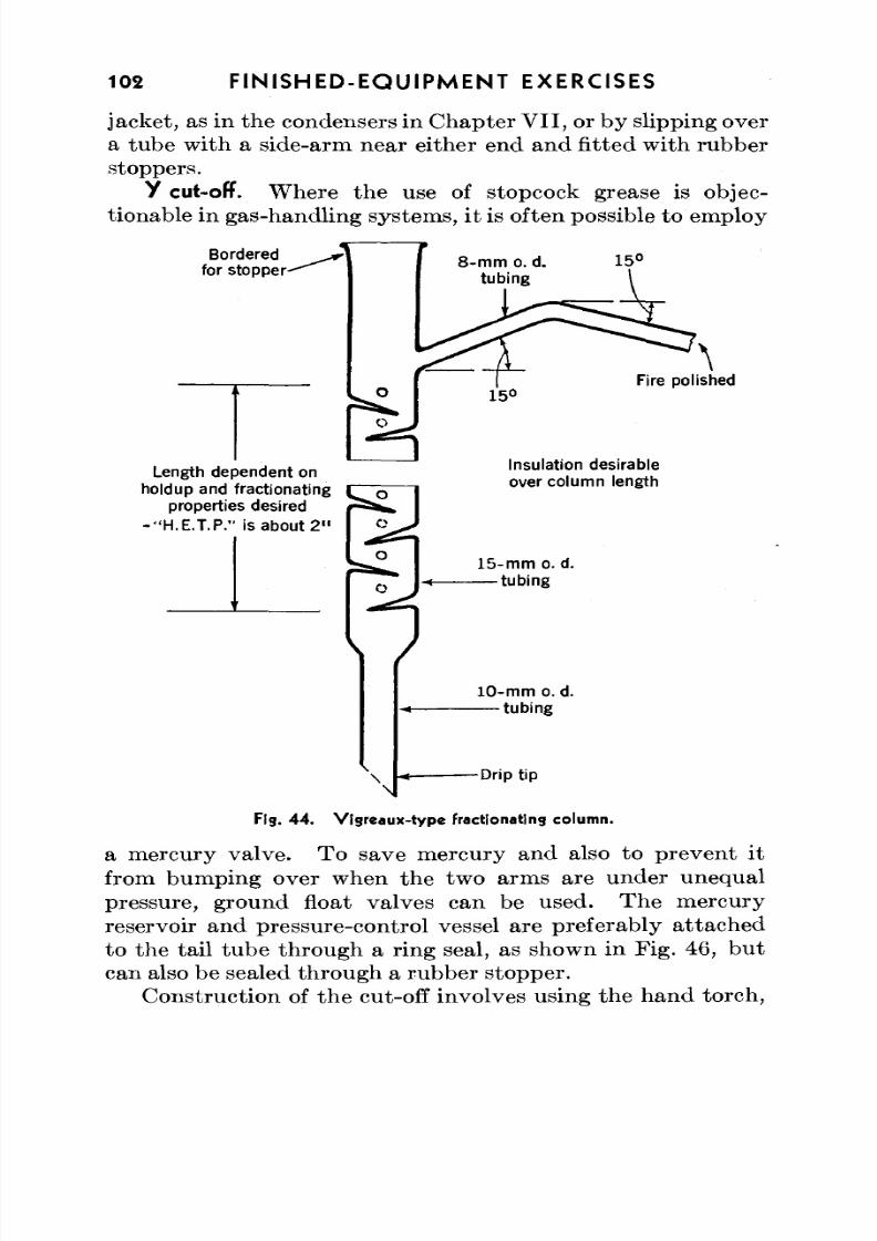
8/3/2019 Techniques of Glass Manipulation - Heldman
http://slidepdf.com/reader/full/techniques-of-glass-manipulation-heldman 114/144
102 FINISHED-EQUIPMENT EXERCISES
jacket, as in the condensers in Chapter V II , or by slipping overa tube with a side-arm near either end and fitted with rubberstoppers.
y cut-off. W here the use of stopcock grease is objec-tionable in gas-handling systems, it is often possible to em ploy
Borderedfor stopper
Fire polished
Length dependent onholdup and fractionating
properties desired
-"H.E .T.P." is about 2 "
Insulation desirableover column length
15-m m o. d.tubing
10-mm o. d.tubing
Drip tip
Fig. 44 . Vigrea ux-typ e fractionating column.
a mercury valve. To save mercury and also to preven t itfrom bumping over when the two arms are under unequal
pressure, ground float valves can be used. Th e mercuryreservoir and pressure-control vessel are preferably attachedto the tail tube through a ring seal, as shown in Fig. 46, butcan also be sealed throu gh a rubber stopp er.
Construction of the cut-off involves using the hand torch,
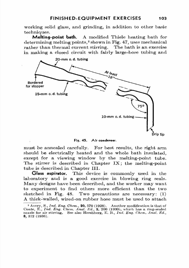
8/3/2019 Techniques of Glass Manipulation - Heldman
http://slidepdf.com/reader/full/techniques-of-glass-manipulation-heldman 115/144
FINISHED-EQUIPMENT EXERCISES 103
working solid glass, and grinding, in addition to other basictechniques.
Melting-point bath. A modified Thiele heating bath fordetermining melting po ints,2
shown in Fig. 47, uses m echanicalrath er th an therm al curren t stirring. Th e ba th is an exercisein making a closed circuit with fairly large-bore tubing and
20-mtn o.d. tubing
Borderedfor stopper
15-mm o. d. tubing
10-mm o.d. tubing-
Fig. 45 . A ir condenser.
must be annealed carefully. Fo r best results, the right armshould be electrically heated and the whole bath insulated,except for a viewing window by the melting-point tube.The stirrer is described in Chapter IX; the melting-pointtube is described in Chapter III.
Glass aspirator. This device is commonly used in thelaboratory and is a good exercise in blowing ring seals.Many designs have been described, and the worker may wantto experiment to find others more efficient than the two
sketched in Fig. 48. Two precautions a re necessary: (1)A thick-walled, wired-on rubber hose must be used to attach
2Avery, S., Ind. Eng. Chem., 20, 570 (1928). An other modification is th at of
Conte, E., Ind. Eng. C hem. Anal. Ed., 2, 200 (1930), which has a ring-sealednozzle for air stirring . See also Hershberg , E. B., Ind. Eng. Chem . Anal. Ed.,8, 312 (1936).
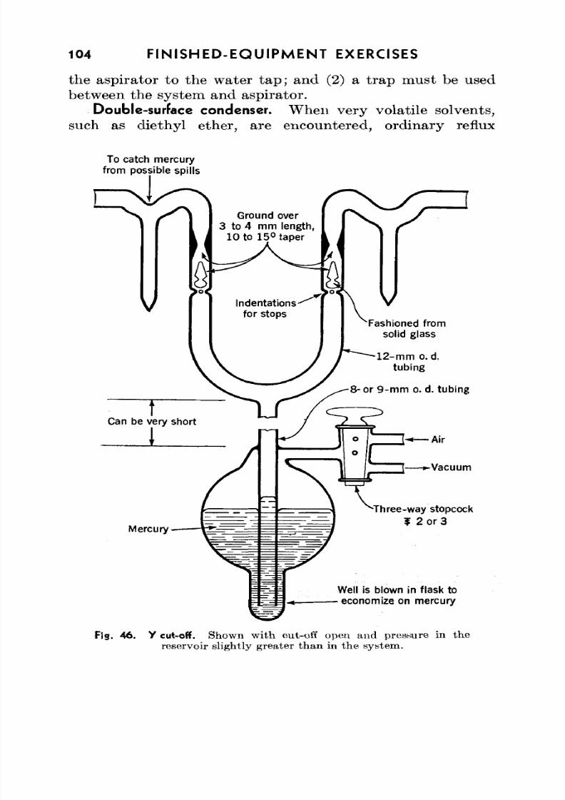
8/3/2019 Techniques of Glass Manipulation - Heldman
http://slidepdf.com/reader/full/techniques-of-glass-manipulation-heldman 116/144
104 FINISHED-EQUIPMENT EXERCISES
the aspirator to the water tap; and (2) a t rap must be usedbetween the system and aspirator.
Double-surface condenser. W hen very volatile solvents,such as diethyl ether, are encountered, ordinary reflux
To catch mercuryfrom possible spills
Ground over
3 to 4 mm length,10 to 15°taper
Three-way stopcock
f 2 or 3
Well is blown in flask to
economize on mercury
Fig. 46. Y cut-off. Shown with cut-off open and pressure in the
reservoir slightly greater than in the system.
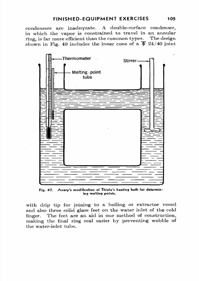
8/3/2019 Techniques of Glass Manipulation - Heldman
http://slidepdf.com/reader/full/techniques-of-glass-manipulation-heldman 117/144
FINISHED-EQUIPMENT EXERCISES 105
condensers are inadequate. A double-surface condenser,in which the vapor is constrained to travel in an annular
ring, is far m ore efficient th an the common types. The designshown in Fig. 49 includes the inner cone of a f" 24/40 joint
Fig. 4 7 . A ve ry 's modif ication of Thiele's heating bath For determin-
ing melting points.
with drip tip for joining to a boiling or extractor vesseland also three solid glass feet on the water inlet of the coldfinger. The feet are an aid in one metho d of construction,making the final ring seal easier by preventing wobble ofthe water-inlet tube.
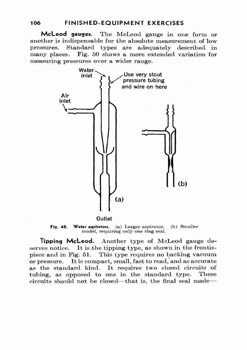
8/3/2019 Techniques of Glass Manipulation - Heldman
http://slidepdf.com/reader/full/techniques-of-glass-manipulation-heldman 118/144
106 FINISHED-EQUIPMENT EXERCISES
McLeod gauges. The McLeod gauge in one form oranother is indispensable for the absolute measurement of low
pressures. Standard types are adequately described inmany places. Fig. 50 shows a more extended varia tion formeasuring pressures over a wider range.
Water>inlet
Air
inlet\ -
\
/Use very stoutpressure tubingand wire on here
\
(b)
(a)
Outlet
Fig. 48 . W ater aspirators, (a) La rger asp irato r, (b) Sm allermodel, requiring only one ring seal.
Tipping McLeod. Another type of McLeod gauge de-serves notice. I t is,the tipping type, as shown in the frontis-
piece and in Fig. 51 . This type requires no backing vacuumor pressure. I t is com pact, small, fast to read, and as accu rateas the stan da rd k ind. I t requires two closed circuits oftubing, as opposed to one in the stan da rd ty pe . Thesecircuits should not be closed—that is, the final seal made—
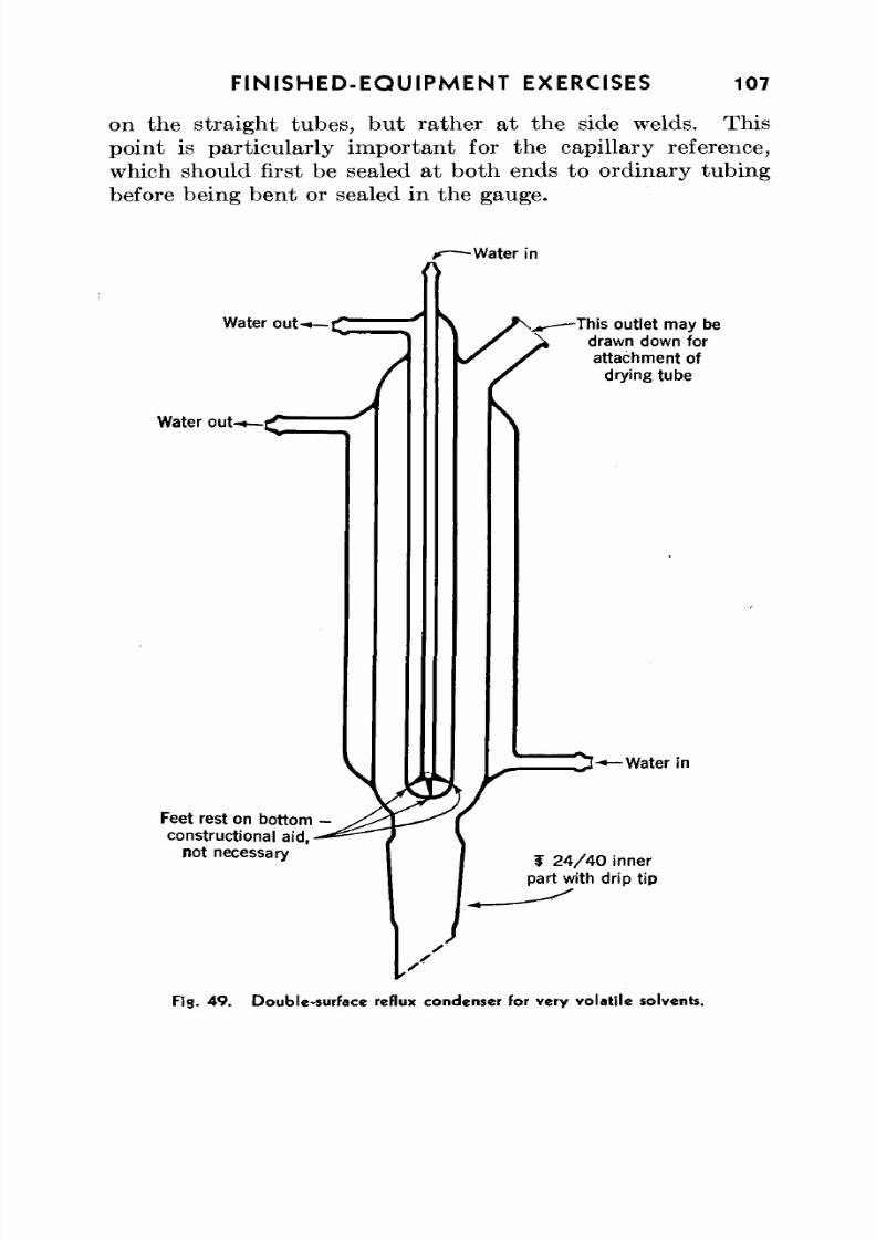
8/3/2019 Techniques of Glass Manipulation - Heldman
http://slidepdf.com/reader/full/techniques-of-glass-manipulation-heldman 119/144
FINISHED-EQUIPMENT EXERCISES 107
on the straight tubes, bu t rather at the side welds. Thispoint is particularly important for the capillary reference,
which should first be sealed at both ends to ordinary tubingbefore being bent or sealed in the gauge.
-Water in
Water out-
Water out-
\
Feet rest on bottom -
constructional aid,
not necessary
This outlet may be
drawn down for
attachment ofdrying tube
\
-Water in
f 24 /4 0 innerpart with drip tip
Fig. 4 9 . Doub le-surface reflux condenser for very vola tile solvents.
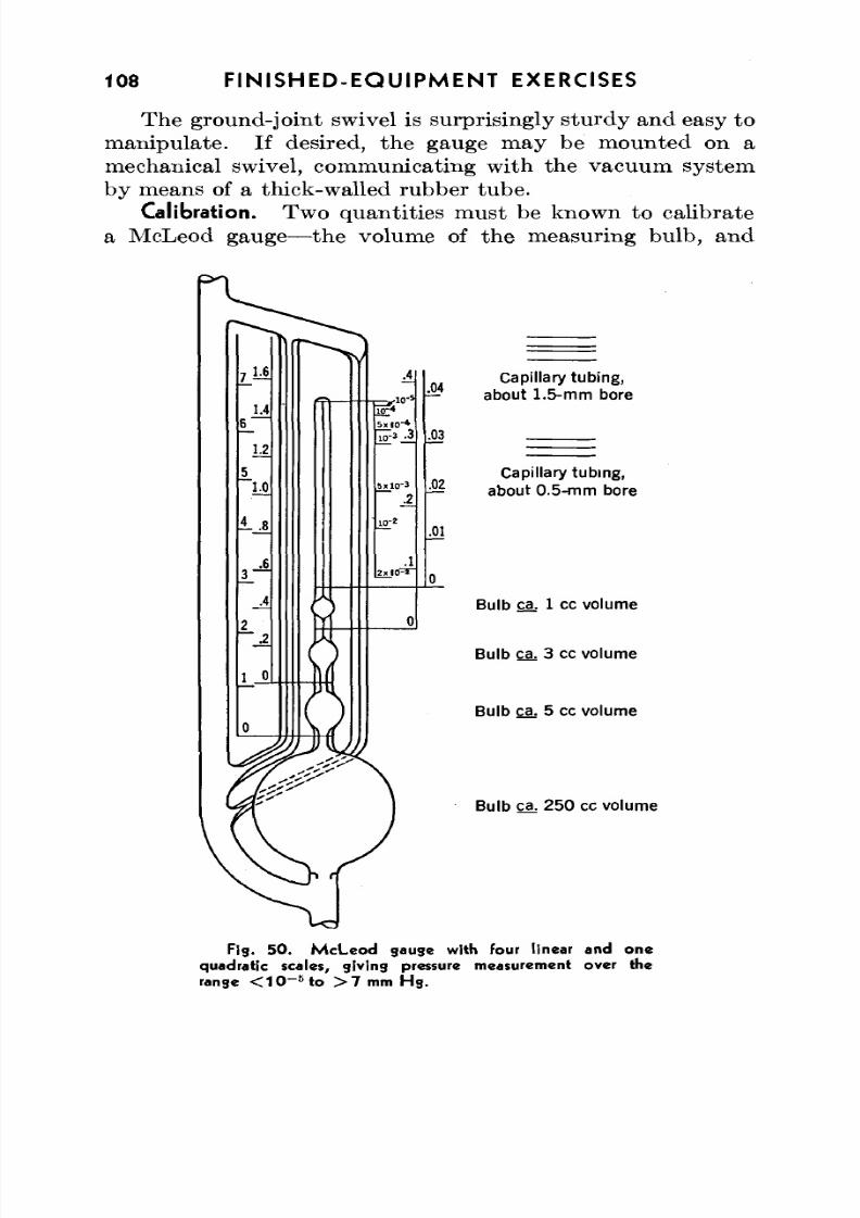
8/3/2019 Techniques of Glass Manipulation - Heldman
http://slidepdf.com/reader/full/techniques-of-glass-manipulation-heldman 120/144
108 FINISHED-EQUIPMENT EXERCISES
The ground-joint swivel is surprisingly sturd y and easy tomanipu late. If desired, the gauge m ay be m ounted on a
mechanical swivel, communicating with the vacuum systemby means of a thick-walled rubber tube.Calibration. Two qu antities must be known to calibrate
a McLeod gauge—the volume of the measuring bulb, and
Capil lary tubing,
— about 1.5-m m bore
Capil lary tubing,
about 0 .5 -mm bore
Bulb ga. 1 cc volume
Bulb ca; 3 cc volume
Bulb ca. 5 cc volume
Bulb ca. 250 cc volume
Fig . 5 0 . M c L e o d gauge with (out l inear and one
quadratic scales, giving pressure measurement over the
rang e < 1 0 ~ 6 t o > 7 mm H g .
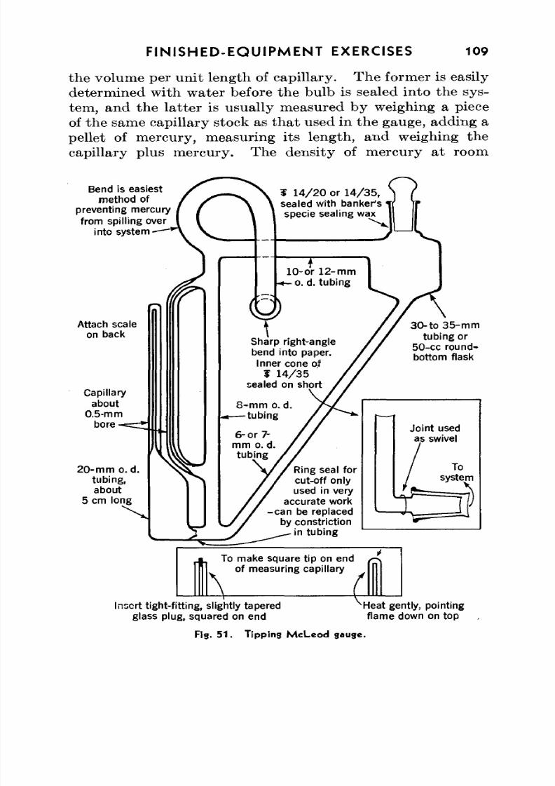
8/3/2019 Techniques of Glass Manipulation - Heldman
http://slidepdf.com/reader/full/techniques-of-glass-manipulation-heldman 121/144
FINISHED-EQUIPMENT EXERCISES 109
the volume per un it length of capillary. The former is easilydetermined with water before the bulb is sealed into the sys-tem, and the latter is usually measured by weighing a pieceof the same capillary stock as that used in the gauge, adding apellet of mercury, measuring its length, and weighing thecapillary plus m ercury. The den sity of mercury at room
Bend is easiestmethod of
preventing mercuryfrom spilling over
into system
Attach scaleon back
Capillaryabout
0.5-mmbore-
20-m m o. d .tubing,about
5 cm long
I 14/2 0 or 14/3 5,sealed with banker'sspecie sealing wax
10-or 12-mmt-o. d. tubing
Sharp right-anglebend into paper.Inner cone of
¥ 1 4 / 3 5sealed on short
8-m m o. d— t u b i n g
Ring seal forcut-off onlyused in very
accurate work-can be replaced
by constriction• in tubing
3 0 - t o 3 5 - m mtubing or
50-cc round-bottom flask
Joint usedas swivel
Tosystem
T )
To make square tip on end
of measuring capillary
Insert tight-fitting, slightly taperedglass plug, squared on end
^Heat gently, pointingflame down on top
Fig. 5 1 . T ipp ing M cLe od gauge.
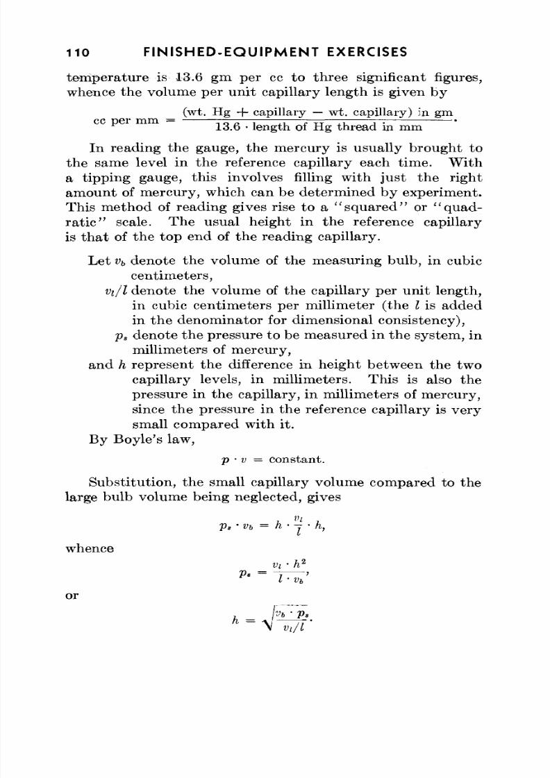
8/3/2019 Techniques of Glass Manipulation - Heldman
http://slidepdf.com/reader/full/techniques-of-glass-manipulation-heldman 122/144
110 FIN ISH ED -EQ UIPM EN T EXERCISES
temperature is 13.6 gm per cc to three significant figures,whence the volume per unit capillary length is given by
(wt. Hg + capillary — wt. capillary) in gmcc p e r m m = .. „ „—; — r—j—^—~r ~j~-
13.6 • length of Hg thre ad in mm
In reading the gauge, the mercury is usually brought tothe same level in the reference capillary each tim e. W itha tipping gauge, this involves filling with just the rightamount of mercury, which can be determined by experiment.This method of reading gives rise to a "squared" or "quad-
ra t i c" scale. Th e usual height in the reference capillaryis that of the top end of the reading capillary.
Let vb denote the volume of the measuring bulb, in cubiccentimeters,
Vi/l denote the volume of the capillary per unit length,in cubic centimeters per millimeter (the I is addedin the denominator for dimensional consistency),
p s denote the pressure to be measured in the system, inmillimeters of mercury,and h represent the difference in height between the two
capillary levels, in millimeters. Th is is also thepressure in the capillary, in millimeters of mercury,since the pressure in the reference capillary is verysmall compared with it.
By Boyle's law,
p • v = constant.
Substitution, the small capillary volume compared to thelarge bulb volume being neglected, gives
p , • vb = h • -j • h,
whence
Vt-h2
l-Vb
or
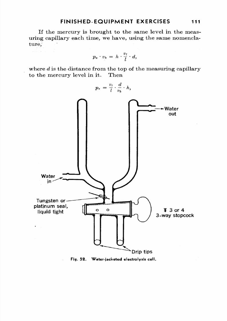
8/3/2019 Techniques of Glass Manipulation - Heldman
http://slidepdf.com/reader/full/techniques-of-glass-manipulation-heldman 123/144
FINISHED-EQUIPMENT EXERCISES 111
If the mercury is brought to the same level in the meas-uring capillary each time, we have, using the same nomencla-
ture,
p s • vb = h • y • d,
where d is the distance from the to p of the m easuring capillaryto the mercury level in it. Then
vi d ,
Waterin
Tungsten orplatinum seal,
liquid tight
-Waterout
f 3 or 43-way stopcock
'Drip tips
Fig. 5 2 . Wa ter- jacketed electrolysis cel l .
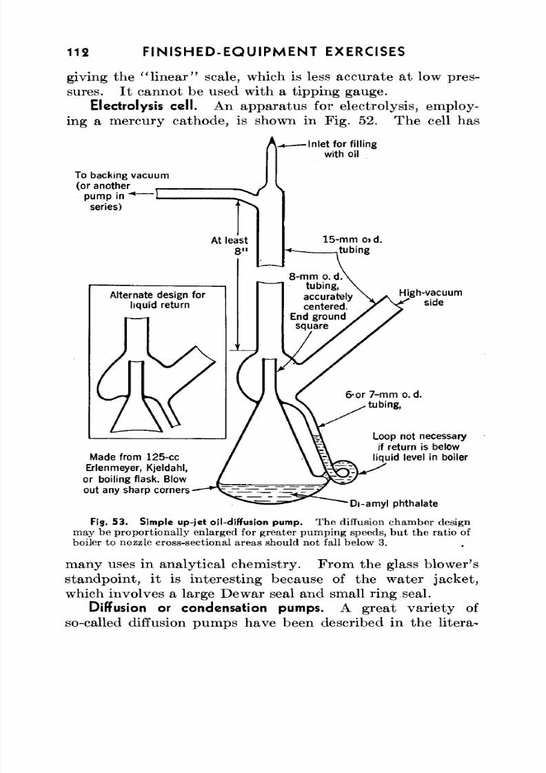
8/3/2019 Techniques of Glass Manipulation - Heldman
http://slidepdf.com/reader/full/techniques-of-glass-manipulation-heldman 124/144
112 FINISHED-EQUIPMENT EXERCISES
giving the "linear" scale, which is less accurate at low pres-sures. It cannot be used with a tipping gauge.
Electrolysis cell. An apparatus for electrolysis, employ-ing a mercury cathode, is shown in Fig. 52. The cell has
Inlet for f i l l ingwith oil
To backing vacuum(or another
pump in "*~
series)
8-mm o. d.tubing,accuratelycentered.
End groundsquare
Alternate design forliquid return
High-vacuumside
Made from 125-ccErlenmeyer, Kjeldahl,
or boiling flask. Blowou t any sharp corners
6-or 7-mm o.d.tubing,
Loop not necessary
if return is belowliquid level in boiler
Di-amyl phthalate
Fig. 53. Simple up-jet oil-diffusion pump. The diffusion chamber design
may be proportionally enlarged for greater pumping speeds, but the ratio of
boiler to nozzle cross-sectional areas should not fall below 3.
many uses in analytical chem istry. Fro m the glass blower'sstandpoint, it is interesting because of the water jacket,which involves a large Dewar seal and small ring seal.
Diffusion or condensation pumps. A great var ie ty of
so-called diffusion pumps have been described in the litera-
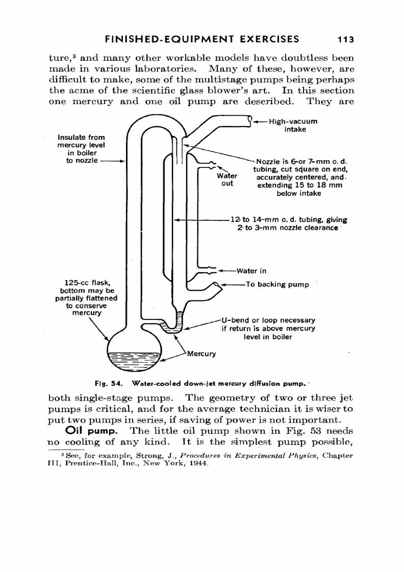
8/3/2019 Techniques of Glass Manipulation - Heldman
http://slidepdf.com/reader/full/techniques-of-glass-manipulation-heldman 125/144
FINISHED-EQUIPMENT EXERCISES 113
ture,3and many other workable models have doubtless been
made in various laboratories. M any of these, however, are
difficult to m ake, some of the m ultistage pum ps being perhapsthe acme of the scientific glass blow er's art . In th is sectionone mercury and one oil pum p are described. Th ey are
Insulate from
mercury level
in boiler
to nozzle •
125-cc f lask,
bottom may be
partially flattened
to conservemercury
\
- H i gh - vacu u m
intake
- Nozzle is 6-or 7- m m o. d.
tubing, cut square on end,
accurately centered, and.
extending 15 to 18 mm
below intake
-12 - to 14 -m m o. d. tubing, g iving
2-to 3-mm nozzle clearance
-Water in
-To backing pump
U-bend or loop necessary
if return is above mercury
level in boiler
^ ^ • = . - _ = = ^ / . ^ M e rc ur y
Fig. 54 . W ater -coo led down-jet mercury diffusion pum p. '
both single-stage pum ps. The geom etry of two or three jetpum ps is critical, and for the average technician it is wiser topu t two pumps in series, if saving of power is not im po rtan t.
Oil pump. The little oil pump shown in Fig. 53 needsno cooling of any kind . I t is the simplest pu m p possible,
3See, for example, Strong, J., Procedures in Experimen tal Physics, Chapter
I I I , Prentice-Hall, Inc., New York, 1944.
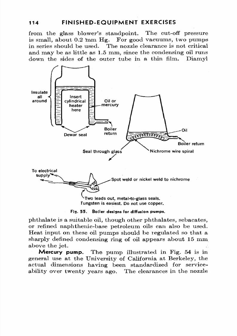
8/3/2019 Techniques of Glass Manipulation - Heldman
http://slidepdf.com/reader/full/techniques-of-glass-manipulation-heldman 126/144
114 FINISHED-EQUIPMENT EXERCISES
from the glass blower's stan dp oin t. The cut-off pressureis small, abo ut 0.2 mm Hg. For good vacuum s, two pum ps
in series should be used. The nozzle clearance is no t criticaland may be as little as 1.5 mm, since the condensing oil runsdown the sides of the outer tube in a thin film. Diamyl
r
Insulate
all <around Insertcylindrical
heaterhere
Oil or-mercury
Seal through glass
Boiler return
Nichrome wire spiral
To electricalsupply
Spot weld or nickel weld to nichrome
Two leads out, metal-to-glass seals.
Tungsten is easiest. Do not use copper.
Fig. 5 5 . Boiler designs for diffusion pumps .
phthalate is a suitable oil, though other phthalates, sebacates,or refined naphthenic-base petroleum oils can also be used.Heat input on these oil pumps should be regulated so that asharply defined condensing ring of oil appears about 15 mm
above the jet.Mercury pump. The pump illustrated in Fig. 54 is in
general use at the University of California at Berkeley, theactual dimensions having been standardized for service-ability over tw en ty years ago, Th e clearances in the nozzle
8/3/2019 Techniques of Glass Manipulation - Heldman
http://slidepdf.com/reader/full/techniques-of-glass-manipulation-heldman 127/144
FIN ISH ED -EQ UIP M EN T EXERCISES 115
area may be varied somewhat without affecting the generalperformance greatly; it will operate over a wide heat input
range; and it does not "cut off" until the backing pressure iswell over 1 mm H g. Tw o such pum ps in series will actuallyoperate with a good water aspirator as backing vacuum.
Pumping speed. A large pumping speed is always desir-able; yet in most instances with glass "static" vacuum sys-tems the use of high-speed diffusion pu m ps is futile. Forexample, no m atter how large the pu m p, two 4-mm bore stop-cocks in series in a vacuum line will cut its pumping speed to
approxim ately 0.5 1 per second.4
Furthermore, the timerequired to achieve the limiting vacuum of the pumps in asystem is often more dependent on the rate of out-gassing ofthe walls than on the pumping speed.
Heaters. Figs. 53 and 54 show the pumps with boilersthat should be heated electrically with a resistance coilwound flat or in a well. W ith such heaters, they will requireup to 250 w. In Fig. 55 are shown two boiler designs whichlower the heat inp ut necessary. Th e Dewar-seal type ofboiler requires only 100 w at most with an insert heater andcan be used on any type of diffusion pump, though it is notdesirable to use it in small oil pum ps. Th e intern al heater isthe neates t type for oil pum ps. The glass-metal seals aremade by the techniques described in Chapter XI, and theheating element can be nichrome or even very thin tungsten.
Less tha n 50 w are needed to operate th e pu m p of F ig. 53 withsuch a heater.
In operation, all-glass diffusion pumps should be heatinsulated or "la gg ed " with asbestos put ty , rope, or tap e fromthe boiler to the beginning of the condenser surface.
The pumping station. As a "final examination" for theglass blower, the construction of a high-vacuum pumpingstation covers practically all the manipulations commonly
encountered at the glass bench and in addition offers an oppor-tunity for the display of technical ingenuity and originalityon the pa rt of the worker. The portable pum ping station
4Calculated from the expression given by Knudsen, M., Ann. d. Physik, 28,
75 , 999 (1908).
8/3/2019 Techniques of Glass Manipulation - Heldman
http://slidepdf.com/reader/full/techniques-of-glass-manipulation-heldman 128/144
116 FIN ISH ED -EQ U IPM EN T EXERCISES
illustrated in the frontispiece is adequate for many purposes,though by no means uniquely so, and is described in some
detail below primarily as a means of comparison with anddiscussion concerning alternative constructions.The frame is made of J-^-in. cold-rolled steel, brazed at the
joints and pa inted b lack. The base (not shown) consists oftwo angle irons, brazed to the side rods and drilled, with aboard set on them and held in place with countersunk boltsand nu ts. The over-all dimensions are as follows: Base, 30 X14 in.; heigh t, 24 in. Th e brazed construction and small size
give it sufficient rigidity so that no angle rods are required,and it is easily lifted and carried about when the glass is inplace.
Larger, permanent frames require cross braces and aremoun ted on a table or low bench. Some m etal work is soclosely allied to glass manipulation that all glass blowersshould familiarize themselves with the elements of metalhandling; construction of a suitable vacuum-bench frame is in
itself a good exercise.The diffusion pump shown is of the up-jet oil type, being
essentially a larger version of the pump shown in Fig. 53.The nozzle is 16-mm o.d., the condensing surface is 25-mmo.d., and the boiler is made from a 250-ml Erlenmeyer flask,wrapped with asbestos rope and heated with a simple flatexternal heater, n ot shown. Optimum heat inp ut is 120 w.
The only novel feature of the pump is the series of catchmentlobes or alembics, which serve to increase th e efficiency of thecondenser a little and, more im po rtan t, partially to fractionatethe pum p oil so th a t the higher vapo r-pressure fractions of theoil are trap ped in the annu lar wells of the lobes. If the pum pwere to be used under conditions in which the oil was fre-quently exposed to air and hence much cracking were to occur,a drain.tube would be sealed to the uppermost alembic.
Details of the method of blowing a catchment lobe are shownin Fig. 56.
It should be noted that there are as few constrictions aspossible in the main pumping line, and that large stopcocksare used (except from oil pump to backing pump, where a
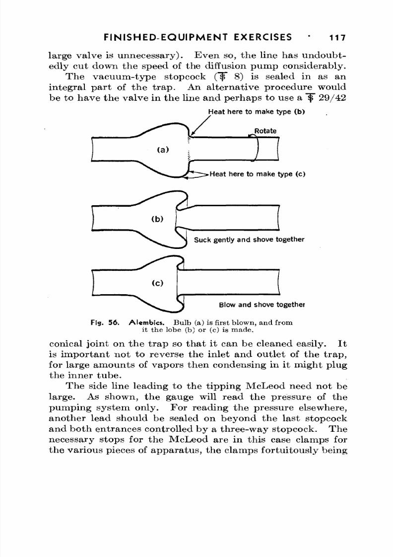
8/3/2019 Techniques of Glass Manipulation - Heldman
http://slidepdf.com/reader/full/techniques-of-glass-manipulation-heldman 129/144
FINISHED-EQUIPMENT EXERCISES 117
large valve is unnecessary). Even so, the line has undoubt-edly cut down the speed of the diffusion pump considerably.
The vacuum-type stopcock ("f" 8) is sealed in as anintegral part of the t rap. An alternative procedure wouldbe to have the valve in the line and perhaps to use a f 29/42
Heat here to make type (b)
Rotate
Heat here to make type (c)
Suck gently and shove together
Blow and shove together
Fig. 56. Alembics. Bulb (a) is first blown, and fromit the lobe (b) or (c) is made.
conical joint on the t rap sothat it can be cleaned easily. It
is important not to reverse the inlet and outlet of the t rap,for large amounts of vapors then condensing in it might plugthe inner tube.
The side line leading to the tipping McLeod need not be
large. As shown, the gauge will read the pressure of the
pumping system only. For reading the pressure elsewhere,another lead should be sealed on beyond the last stopcockand both entrances controlled by a three-way stopcock. The
necessary stops for the McLeod are in this case clamps for
the various pieces of apparatus, the clamps fortuitously being
8/3/2019 Techniques of Glass Manipulation - Heldman
http://slidepdf.com/reader/full/techniques-of-glass-manipulation-heldman 130/144
118 FIN ISH ED -EQ U IPM EN T EXERCISES
placed about right. Th ey are sleeved w ith rubber tubingwhere the gauge can touch them . Th e scale has no t yet
been attach ed to th e McLeod gauge, which reads 9 X 10~
3
mm Hg, representing the pressure obtained by the mechanicalfore pum p when the system was first tested for leaks. Afterone hour's operation of the diffusion pump, the McLeod indi-cated approximately 5 X 10~
5mm, about the limit of the
gauge, and, when liquid air was placed around the trap, a"stic k va cu u m " (mercury sticking at the top of the m easuringcapillary) was ob tained . Such behavior is typ ical of static
pumping systems.Even though a "stick vacuum" was obtained, there are
too many stopcocks and joints for really high-vacuum work,in which the parts should be fused together, with as fewstopcocks as possible, or preferably mercury cut-offs withliquid-air traps for mercury vapor, and as much glass as pos-sible baked out in vacuo at 350° C. The system shown willnot achieve its base pressure' (ultimate p ressure without p um p-ing load due to vapor pressure of the lubricants and the slowrate of cracking of the pump oil) until it has been pumpedcontinuously for a week or so, for the stopcock lubricants,walls, and sealing wax will continuously out-gas. Onthe other hand, the use of stopcocks, joints, and sealingwax greatly facilitates handling, dismantling, and cleaningoperations.
8/3/2019 Techniques of Glass Manipulation - Heldman
http://slidepdf.com/reader/full/techniques-of-glass-manipulation-heldman 131/144
Glossary
A . Nom enclature of Glasses
T HE nomenclature of glasses is so important and funda-mental to the understanding of this book that a complete
discussion of terminology is given here. Soft glass, lime-sodaglass, and the like, unless further qualified, are general terms
and refer to glasses with expansion coefficients of the orderof 80 to 120 X 10~
7per degree C. Lead glass refers to a soft
glass containing lead. How ever, in the pa st 25 years, theuse of Corning glasses has become so widespread in thelaboratory that some confusion has resulted regarding theirdesignations.
"Pyrex," "Nonex," and "Vycor" are registered trade-
m arks owned by the Corning Glass W orks, Corning, N .Y.,under which are sold over one hundred different glass com-positions, each identified by num ber. The trade-m arks denoteorigin and have no composition significance. ParticularCorning glasses can be identified only by number, since morethan one glass may be found under each of the trade-marks.Thus the glass popularly known to scientists as "Pyrex" iscorrectly called "Pyrex-brand chemical-resistant glass No.
774" or abbreviated as "774"— not as "Pyrex," since otherPyrex-brand glasses are different from it, whereas "774" isunique.
In th is book, Pyrex-b rand chemical-resistant glass No. 774is referred to as Pyrex N o. 774 or 774. W hen the term" P y re x " alone is used, it refers to Pyrex glasses as a collectivewhole.
"Nonex No. 772" or "772" refers to the glass popu-larly but erroneously known in the laboratory as "Nonex."No confusion is likely to arise from the naming of other seal-ing-in glasses, which are ordinarily spoken of by number—as,for example, 705AJ.
119
8/3/2019 Techniques of Glass Manipulation - Heldman
http://slidepdf.com/reader/full/techniques-of-glass-manipulation-heldman 132/144
120 GLOSSARY
All glasses referred to by number in this book are manu-factured by the Corning Glass W orks.
B. Alphabetical List of Terms UsedABRASIVE. Hard material, either powder or solid, used in grinding
away surfaces.
ALEMBIC. Lobe for catching liquid running down the walls of atube.
AMORPHOUS. Having no definite crystalline pa tter n. The termmay be applied to glasses and also to certain solids likelampblack (carbon).
ANNEALING. Slow cooling to relieve thermal strains set up in hotglass.
ANNEALING POINT. Temperature at which a glass can be annealedin 15 min. The viscosity a t this tem peratu re is 2.5 X 10
13
poises.
"A N T I - B U MPE R . " Device for eliminating bumping or violent boil-ing in a solution being heated.
ANNULAR ORIFICE. Open space between two coaxial tubes.
ASPIRATOR. Simple liquid-flow entrainment pump for gases.
Ax is. A straight line, real or imag inary, on which an object maybe symmetrically rotated and still present the same appear-ance.
" B A C K F I R E . " Condition in which flame velocity is greater thangas flow rate, so tha t flame b urns back into torch.
BAROMETER. Device for measuring the pressure exerted by the
earth's atmosphere.BEADING. Applying a bead of glass around a metal wire.
BLAST LAMP. Burner with inlet for compressed air and oxygen.
BLOW TUBE. Length of light rubber tubing used to transmit airpressure from mouth to glass being blown.
BORDERING. Flaring and thickening a tubing end.
BRAZING. Soldering with brass.
BRUSH FLAME. A diverging flame with wide, not-well-defined end.BULGING. Putting a small bulb in tubing, or merely increasing its
o.d. slightly a t one place. See also MA R ! A .
BUNSEN BURNER. Laboratory burner using aspirator effect offlowing gas to inject air into flame.
8/3/2019 Techniques of Glass Manipulation - Heldman
http://slidepdf.com/reader/full/techniques-of-glass-manipulation-heldman 133/144
GLOSSARY 121
BURNER. Apparatus for producing a controlled flame.
B & S. Arbi trary scale for diameters of circular cross-sections.No. 28 B & S wire is 0.0126 in. in diam eter.
CALIPERS. Measuring device for inside and outside dimensions.
CANE. Cylindrical solid glass.
CAPILLARY. Small-diameter bore. Unless otherwise sta ted , capil-lary tubing refers to thick-walled tubing.
CATCHM ENT LOBE. See ALEM BIC.
CHTJCK. Clamp or holder.
COE FFICIEN T OF EXPANSION. See TH ERM AL EXPANSION.
COHESION. Tendency of parts of the same material to staytogether.
COLOR TEMPERATURE. Color due to radiation which is common toall bodies. A dull red becomes apparen t about 650° C indaylight, changing to orange, yellow, and white as thetemperature is increased to about 1400° C.
CONDENSATION PUMP. See D IFFUS ION PUMP.
CROSS-FIRES. TWO burners or flames pointed at each other.
CRYOPHORUS. Device for demonstrating heat of vaporization.
CRYSTAL. A solid with definite, repeated micro structure.
CUT-OFF. Valve for gas flow utilizing a liquid which can be raisedor lowered past the joint of a Y.
DEVITRIFICATION. Process of crystal formation from a glassy orvitreous material.
DEWAR SEAL. W eld in which an inner and outer tu be a re joinedat one end without any extension of tubing.
DIDYMIUM. Mixture of two rare earths, neodymium and praseo-dymium, used in glass-blowing goggles because of its selec-tive absorption of sodium light.
DIFFUSION PUMP. Pump for gases utilizing molecular bombard-ment, by vapor from a boiling liquid, of gases in a system.
Disc SEAL. Glass-to-metal seal in which a thin disc of metal issealed between two glass tubes.
D O W E L . Solid cylindrical rod.
D U ME T . Copper-sheathed iron-nickel alloy used for lead-in wiresin incandescent lamps.
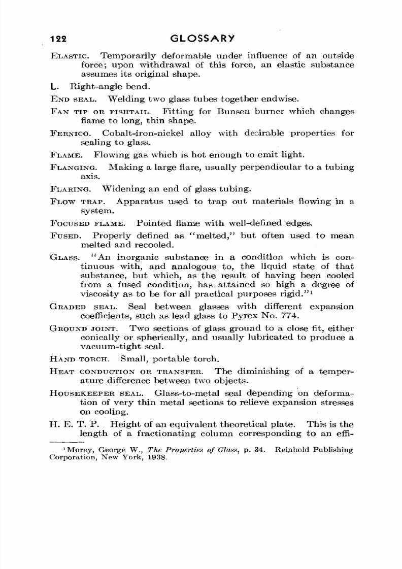
8/3/2019 Techniques of Glass Manipulation - Heldman
http://slidepdf.com/reader/full/techniques-of-glass-manipulation-heldman 134/144
122 GLOSSARY
ELASTIC. Temporarily deformable under influence of an outsideforce; upon withdrawal of this force, an elastic substanceassumes its original shape.
L. Right-angle bend.
END SEAL. W elding two glass tubes together endwise.
FAN TIP OR FISHTAIL. Fitting for Bunsen burner which changesflame to long, thin shape.
FERNICO. Cobalt-iron-nickel alloy with desirable properties forsealing to glass.
FLAME. Flowing gas which is hot enough to emit light.
FLANGING. M aking a large flare, usually perpendicular to a tub ingaxis.
FLARING. W idening an end of glass tubing .
FLOW TRAP. Apparatus used to trap out materials flowing in asystem.
FOCUSED FLAME. Pointed flame with well-defined edges.
FUSED. Properly defined as "melted," but often used to mean
melted and recooled.GLASS. "An inorganic substance in a condition which is con-
tinuous with, and analogous to, the liquid state of thatsubstance, but which, as the result of having been cooledfrom a fused condition, has attained so high a degree ofviscosity as to be for all practical purposes rigid."
1
GRADED SEAL. Seal between glasses with different expansioncoefficients, such as lead glass to Pyrex No. 774.
GROUND JOINT. TW O sections of glass ground to a close fit, eitherconically or spherically, and usually lubricated to produce avacuum-tight seal.
HAND TORCH. Small, portable torch.
H E A T CONDUCTION OR TRANSFER. The diminishing of a temper-ature difference between two objects.
HOUSEKEEPER SEAL. Glass-to-metal seal depending on deforma-tion of very thin metal sections to relieve expansion stresses
on cooling.H. E. T. P. Heigh t of an equivalent theoretical plate. This is the
length of a fractionating column corresponding to an effi-
'Morey, George W. , The Properties of Olass, p. 34. Reiphold PublishingCorporation, New York, 1938.
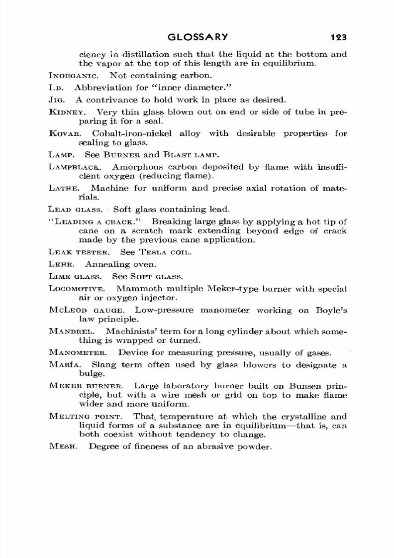
8/3/2019 Techniques of Glass Manipulation - Heldman
http://slidepdf.com/reader/full/techniques-of-glass-manipulation-heldman 135/144
GLOSSARY 123
ciency in distillation such that the liquid at the bottom andthe vapor at the top of this length are in equilibrium.
INORGANIC. Not containing carbon.
I.D. Abbreviation for "inner diameter."
JIG. A contrivance to hold work in place as desired.
KIDNEY. Very thin glass blown out on end or side of tube in pre-paring it for a seal.
KOVAR. Cobalt-iron-nickel alloy with desirable properties forsealing to glass.
LAM P. See BUR NER and BLAS T LAMP.
LAMPBLACK. Amorphous carbon deposited by flame with insuffi-cient oxygen (reducing flame).
LATHE. Machine for uniform and precise axial rotation of mate-rials.
LEAD GLASS. Soft glass containing lead.
"LEADING A CRACK." Breaking large glass by applying a hot tip ofcane on a scratch mark extending beyond edge of crack
made by the previous cane application.LE AK TESTER. See TE SLA COIL.
L E H R . Annealing oven.
LIM E GLASS. See S OFT GLASS.
LOCOMOTIVE. Mammoth multiple Meker-type burner with specialair or oxygen injector.
MCLEOD GAUGE. Low-pressure manometer working on Boyle'slaw principle.
MANDREL. M ach inists' term for a long cylinder abo ut which some-thing is wrapped or turned.
MANOMETER. Device for measuring pressure, usually of gases.
MARIA. Slang term often used by glass blowers to designate abulge.
MEKER BURNER. Large laboratory burner built on Bunsen prin-ciple, but with a wire mesh or grid on top to make flame
wider and more uniform.MELTING POINT. That temperature at which the crystalline and
liquid forms of a substance are in equilibrium—that is, canboth coexist without tendency to change.
M E S H . Degree of fineness of an abrasive powder.
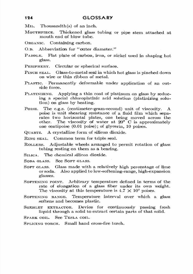
8/3/2019 Techniques of Glass Manipulation - Heldman
http://slidepdf.com/reader/full/techniques-of-glass-manipulation-heldman 136/144
124 GLOSSARY
MIL. Thousandth(S) of an inch.
MOUTHPIECE. Thickened glass tubing or pipe stem attached atmouth end of blow tube.
ORGANIC. Containing carbon.
O.D. Abbreviation for "outer diameter."
PADDLE. Flat plate of carbon, iron, or nickel used in shaping hot
glass.
PERIPHERY. Circular or spherical surface.
PINCH SEAL. Glass-to-metal seal in which hot glass is pinched down
on wire or thin ribbon of metal.
PLASTIC. Permanently deformable under application of an out-
side force.
PLATINIZING. Applying a thin coat of platinum on glass by reduc-
ing a special chloroplatinic acid solution (platinizing solu-
tion) on glass by heating.
POISE. The c.g.s. (centimeter-gram-second) unit of viscosity. A
poise is unit shearing resistance of a fluid film which sepa-
rates two horizontal plates, one being moved across theother. The viscosity of water at 20° C is approximately
one centipoise (0.01 poise); of glycerin, 10 poises.
QUARTZ. A crystalline form of silicon dioxide.
RING SEAL. Common term for triple seal.
ROLLERS. Adjustable wheels arranged to permit rotation of glass
tubing resting on them as a bearing.
SILICA. The chemical silicon dioxide.
SODA GLASS. See SOFT GLASS.
SOFT GLASS. Glass made with a relatively high percentage of lime
or soda. Also applied to low-softening-range, high-expansion
glasses.
SOFTENING POINT. Arbitrary temperature denned in terms of the
rate of elongation of a glass fiber under its own weight.
The viscosity at this temperature is 4.7 X 10⁷
poises.
SOFTENING RANGE. Temperature interval over which a glass
softens and becomes plastic.
SOXHLET EXTRACTOR. Device for continuously passing freshliquid through a solid to extract certain parts of that solid.
SPARK COIL. See TESLA COIL.
SPLICING TORCH. Small hand cross-fire torch.
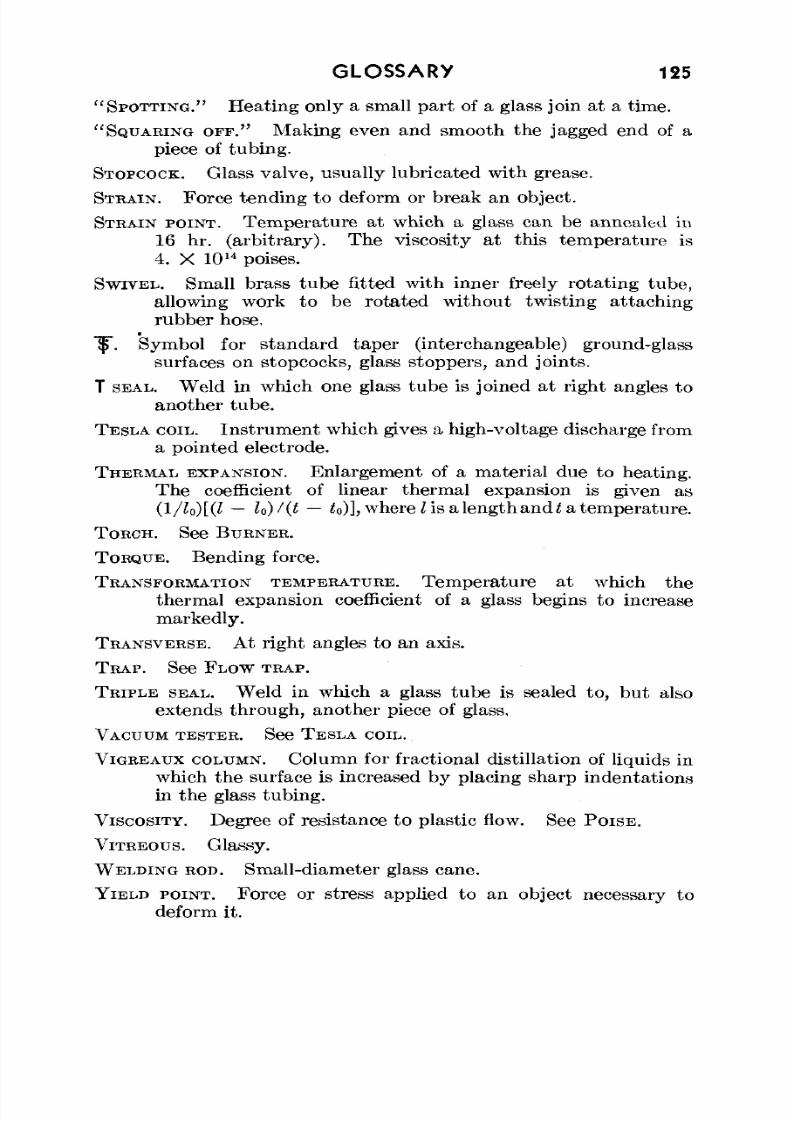
8/3/2019 Techniques of Glass Manipulation - Heldman
http://slidepdf.com/reader/full/techniques-of-glass-manipulation-heldman 137/144
GLOSSARY 125
"SPO T T I N G . " Heating only a small part of a glass join at a time.
"SQUARING OFF." Making even and smooth the jagged end of apiece of tubing.
STOPCOCK. Glass valve, usually lubricated with grease.
STRAIN. Force tending to deform or break an object.
STRAIN POINT. Temperature at which a glass can be annealed in16 hr. (a rbitra ry) . The viscosity at this tem pera ture is4. X 10H poises.
SWIVEL. Small brass tube fitted with inner freely rotating tube,allowing work to be rotated without twisting attaching
rubber hose.7$. Symbol for standard taper (interchangeable) ground-glass
surfaces on stopcocks, glass stoppers, and joints.
T SEAL. W eld in w hich one glass tub e is joined at right angles toanother tube.
TESLA COIL. Instrument which gives a high-voltage discharge froma pointed electrode.
THERMAL EXPANSION. Enlargement of a material due to heating.
The coefficient of linear therm al expansion is given as(l/lo)[(l — U)/(t — to)], where I is a length and t a temperature.
TORCH. See BUR NER .
TORQUE. Bending force.
TRANSFORMATION TEMPERATURE. Temperature at which thethe rm al expansion coefficient of a glass begins to increasemarkedly.
TRANSVERSE. At right angles to an axis.
TRA P. See FLOW TRAP.
TRIPLE SEAL. W eld in which a glass tub e is sealed to , bu t alsoextends through, another piece of glass.
VACUUM TESTER . See TE SL A COIL.
VIGREAUX COLUMN. Column for fractional distillation of liquids inwhich the surface is increased by placing sharp indentationsin the glass tubing.
VISCOSITY. Degree of resistance to plas tic flow. See P O I S E .
VITREOUS. Glassy.
WELDING ROD. Small-diameter glass cane.
YIELD POINT. Force or stress applied to an object necessary todeform it.

8/3/2019 Techniques of Glass Manipulation - Heldman
http://slidepdf.com/reader/full/techniques-of-glass-manipulation-heldman 138/144
8/3/2019 Techniques of Glass Manipulation - Heldman
http://slidepdf.com/reader/full/techniques-of-glass-manipulation-heldman 139/144
Index
Air, compressed, for heating, 8Air condenser, 101, 103Alembic, 116, 117Annealing:
burners for, 8
methods of, 5-6Annealing oven, 5, 18Annealing point (table), 2"Ant i -bumper ," 100-101Asbestos paper, 15, 19Asbestos tape, 15, 20, 21Aspirator, glass, 103, 106Avery, S., 103
B
Bahls, W. E., 99Ball-and-socket joint, see Sphericaljoint
Barometer, 101Beeswax, 18Bellows, expansion, 76-77Bench, glass blower's, 19-22Bends:
angle-seal type of, 30, 74large, 73-74sharp, 30, 74
silica, 85-86spiral, 30, 75techniques in making, 29-30, 32,
40-41T-seal type of, 30, 74U,30
Blast torch, 9Blowing:
cutting glass by, 25involving one piece of glass, 36-41techniques in, 37
Blow tube, 15, 20, 21Bomb tube, 33Bordering, see FlaringBrace (see also Clamp) :
flow-trap, 54—56ring-seal, 53
Bulb:auxiliary, in test-tube end, 31in end of tube, 39in middle of tube, 39-40
Bulge, 34-35Bunsen burner , 8Buret, repairing, 32
Burger, E. E., 3, 99Burners (see also Torches) :glass, 11placement of, 22types (see also und er specific types,
as Bunsen, Cross-fires, etc.),8-11
C
Calibration of McLeod gauge, 108-112
Calipers, 14, 20, 21Cane :cutting glass with, 24welding, 13-14, 20, 21
Capillary tubing, techniques of ma-nipulation of, 72-73
Carbon tools:dowels, 18, 20, 21rods, 18, 20, 21use of, in flaring, 27-28
Carborundum:
equipment, 18use of, in grinding, 82Cell, electrolysis, 111, 112Cement, de Khotinsky, 70Chromium, 98-99Circuit, closing a, 67-68Clamp (see also Brace), for spherical
joints, 80Closing a circuit, 67-68Coil:
glass, methods of making, 75
Tesla, 69Column, Vigreaux, 101, 102Condensation pumps, ii , 112-115Condenser:
air, 101, 103double-surface, 104, 107
127

8/3/2019 Techniques of Glass Manipulation - Heldman
http://slidepdf.com/reader/full/techniques-of-glass-manipulation-heldman 140/144
128 INDEX
Condenser (Cord.):water-jacketed, 59-60
Conical joint:grinding, 81, 82
manipulation of, 81refinishing, 81, 82types of, 78-79
Constrictions, 71-72Conte, E., 103Copper:
expansion coefficient of (table), 3sealing, to glass, 94-98
Corning glasses (see also Pyrex No.774, Nonex N o. 772, Vycor, andGlass):
nomenclature of, 119-120physical properties of (table), 2
Cracks, healing of, 41Cross-fires:
foot pedals for, 11-12glass, 11multiple-jet, 9, 20, 21single-jet, 9use of, 11-12, 46
Cry op horus, 74—75Cut-off, y, 102 ,104
Cutting glass:by blowing out, 25by "leading a crack," 24hot-wire method of, 24-25use of cane in, 24with file, 23-24
D
Definitions of terms used, 120-125De Khotinsky cement, 70
Devitrification:curing, 6of silica, 86
Dewar seal:techniques of making, 62-65uses of, 64-65
Didymium goggles, 13, 20, 21Diffusion pump, ii, 112—115Dowel, 18, 20, 21Drilling glass, 82Dume t :
expansion coefficient of (table), 3sealing, to glass, 93-94
E
Electrolysis cell, 111, 112E n d :
bulb, 39
E nd (Cont.):test- tube, 31, 36-38vial, 38-39
End seals:
capillary, 72-73rotation method for, 42—44"spot t ing" method for , 44-45with different-diameter tubes, 43,
45-46with same-diameter tubes, 42-45
Etching glass, 82Exercises, 100-118Expansion:
in glass-to-metal seals, 87-88of Kov ar " A " vs. 705AJ, 91
Expansion bellows, 76-77Expansion coefficient:
of glasses (table), 2of metals and alloys (table), 3
Fan t ip:bending with, 32use of, 8
Fernico:
expansion coefficient of (table), 3sealing, to glass, 91-93File:
types of, 15, 17, 20, 21use of, in breaking glass, 23
Fire polishing, 27First aid, 13Fishtail , see Fan t ipFlames, 7-12Flanging, 32Flaring, 27-29Flaring tool:
types of, 18, 20, 21use of, 27-29
Flask holder, 18, 20, 21Flowmeter, gas, 61, 62Flow traps, ii , 52-59Forceps, 18, 20, 21
G
Gas:for heating, 8
flowmeter for, 62, 63Gauge, McLeod, ii, 106-112Gauze, wire, 29Glass:
ch arac te ris tic s of, 1—3color of, 14cutting tools for, 15, 17

8/3/2019 Techniques of Glass Manipulation - Heldman
http://slidepdf.com/reader/full/techniques-of-glass-manipulation-heldman 141/144
INDEX 129
Glass (Cont.):definition of, 1, 122distinguishing b etween types of, 14 -
15nomenclature of types of, 119—120physical properties of (table), 2properties of, 1-6solid, 83-84stock, 13
. types of, 1-2, 119Glass-to-metal seals, 87-99Glassy state, 1Glossary:
definitions of terms, 120—125nomenclature of glasses, 119-120
Goggles, didymium, 13, 20, 21Graded seals, 4, 86Grinding:
equipment for, 18refinishing ground joints by, 81-82rough, 82
Ground joint:grinding, 81-82lubrication of, 80manipulation of, 81refinishing, 81-82
types of, 78-80
H
Handle , temporary:of cane, 33of tubing, 34-35
Hand torch:replaceable tips for, 9, 20, 21types of, 9, 20, 21use of, 33, 66-69
Heaters for pumps, 114, 115
Heating equipment, 7—12Hershberg, E. B., 103Hot-wire method of cutting glass, 17,
24-25Housekeeper, W. G., 94, 99Housekeeper seals:
disc, 95-97ribbon, 94-95tubular , 97-98
Hull, A. W., 3, 99Hydrogen fluoride, use of:
in cleaning silica, 86in curing devitrification, 6in etching glass, 82
Inner seal, see Ring sealIron, 98-99
Jig for T seals, 50Joint , ground, 77-82
K
Kidney:example of, 43in preparing capillary, 73
Kjeldahl trap, 61Knife for cutting glass, 17Knudsen, M., 115Kovar :
expansion coefficient of (table), 3expansion of, 91sealing, to glass, 91-93
L
L, see BendLa mp, see Torch and BurnerLampblack, 5-6Lathe, 18Lead glass:
composition of, 2
Corning Gl, physical properties of(table), 2
use of, in platinum seals, 3, 88-89"Leading a crack," 24Leaks, detection and repair of, 69-70Lehr, 5Lime glass:
composition of, 2Corning G8, physical properties of
(table), 2use of, in platinum seals, 88, 89
Li ne ar expansio n coefficient, see Ex-pansion coefficient
Lobe, catchment, 116, 117"Locomotive" burner , 8Lubrication of ground surfaces, 80
M
McLeod gauge:calibration of, 108-112tipping, ii, 29, 106-108, 109
types of, 106Mandrel, use of, in making coil, 75Manometer , 101Marfa, see BulgeMarking glass, 82Masonite, 19Meker burner, 8, 20, 21

8/3/2019 Techniques of Glass Manipulation - Heldman
http://slidepdf.com/reader/full/techniques-of-glass-manipulation-heldman 142/144
130 INDEX
Melting-point bath, 103, 105Melting-point tube, 33Mercury, overflow trap for, 61Mercury pump, 113, 114-115
Metal-to-glass seals, 87-99Molybdenum:
expansion coefficient of (table), 3sealing, to glass, 90-91
Morey, George W., viii, 2, 122Mouthpiece, 15, 20, 21
N
National Safety Council, 12Navias, L., 99
Nickel, 98-99Nomenclature of glasses, 119—120Nonex No. 772:
composition of, 2in Housekeeper seals, 94, 96—97in tungsten seals, 89-90nomenclature of, 119-120physical properties of (table), 2
Nozzle, 32
O
Oil pump, ii, 112, 113-114, 116Oxide film, 87Oxygen for heating, 8
Paddles, carbon, 18Paraffin, 18Pencil, vibratory, 82Phillips, C. J., viii
Physical properties:of glasses (table), 2of Kovar " A " vs . 705 AJ, 91of metals and alloys (table), 3
Picein, 70Pilot light, 8Pinch seals, 93-94Platinizing of glass, 98Pla t inum:
expansion coefficient of (table), 3sealing to glass, 3, 88-89
Point :pulling, 31, 32use of, in sealing tube end, 36-37
Porcelain:scratching capillary with, 32, 34sealing, to glass, 99
Protector, face and eye, 20, 21
"Pull ing a point ," 31, 32P u m p :
heaters for, 114, 115mercury, 113, 114-115oil, ii, 112, 113-114, 116speed of, 115
Pumping station, ii , 115-118Pyrex No. 774:
composition of, 2nomenclature of, 119-120physical properties of (table), 2
Q
Quartz, see Silica
R
Reduction valve, 12Refrigerant, 33Ribbon seals, 93-94Ring seal:
axial, 52-61braces for, 53, 54-56techniques in constructing, 52-62
through side of tube, 62Robertson, G. R., 101Rod:
carbon, 18, 20, 21cutting glass with, 24welding, 13-14, 20, 21
Rollers:description of, 18-19, 20, 21rotation of glass on, 26
Rotation of glass:in bending, 29
during blowing, 37in end seals, 42-44, 46methods of, 25-27in "pulling a point," 32reasons for, 4-5on rollers, 18, 19, 26
S
Saw for glass, 17
Sealing off:of bomb tubes, 33in vacuo, 68
Sealing wax, banker's specie:on glass blower's bench, 20, 21for ground surfaces, 80-81for pinhole leaks, 70

8/3/2019 Techniques of Glass Manipulation - Heldman
http://slidepdf.com/reader/full/techniques-of-glass-manipulation-heldman 143/144
INDEX 131
Seals:Dewar, 62-65end, 42-46graded, 86Housekeeper, 94-98metal-to-glass, 87-99porcelain-to-glass, 99ring, 52-62silica, 85solder, 98"suck," 50-51T, 46-50test- tube-end, 36-38y , 5 0
705AJ:expansion of, 91physical properties of (table), 2use of:
in Kovar seals, 91-92in molybdenum seals, 91
705AO, use of, in Fernico seals, 92Silica:
devitrification of, 86graded seals to, 86manipulation of, 84-86physical properties of (table), 2
uses of, 84Soapstone, 19, 20, 21Soda glass, see Lime glassSoftening point (table), 2Softening range, 1Soft glass (see also Lead glass and
Lime glass):composition of, 1-2physical properties of (table), 2
Solder seals, 98Spherical joint:
clamps for, 80grinding of, 82manipulation of, 81refinishing of, 82use of, 79
Spirals, 30, 75Splicing torch, 9, 68-69"Spot t ing ," 44-45"Squaring off," 29Standard taper , 78Stirrer, glass, 83-84
Stopcocks:grinding of, 81-82manipulation of, 81refinishing of, 81-82types of, 77-78
Stoppers, 15, 20, 21Storage of glass, 14
Stra in:in heating, 4in sealing, 3, 4
Strain point (table), 2Strong, John, viii , 113"Suck" sea l , 50-51Support for hot glass, 20, 21Swivel, 15, 16, 20, 21
T seal:capillary, 72-73large, 49techniques in making, 46-50
T, 78Tesla coil, 69Test- tube end, 31, 36-38Thermal behavior of glasses, 4-5Thermal expansion, see ExpansionTorches (see also Burners) :
blast, 9glass, 11, 12hand, 9, 10, 20-22, 66-69permanent , 9, 10splicing, 9, 68-69
T r a p :flow, ii , 52-59Kjeldahl, 61for mercury overflow, 61
Transite, 19, 20, 21Triple seal, see Ring sealTube :
bulb in middle of, 39-40sealing end of, 36-39
Tungs ten:expansion coefficient of (table), 3
seals to glass, 89-90Tweezers, 18, 20, 21
U
U bend, 30Uranium glass, 90, 91
Vacuum:leak in, 69-70sealing off in, 68
Vacuum pump, i i , 112-115Vacuum tester (detector), 69Vial end, 38-39Vigreaux column, 101, 102Viscosity of glasses, 1, 2Vise, pin, 20, 21, 88Vitreous silica, see Silica

8/3/2019 Techniques of Glass Manipulation - Heldman
http://slidepdf.com/reader/full/techniques-of-glass-manipulation-heldman 144/144
132 INDEX
Vycor glasses:nomenclature of, 119-120physical properties of (table), 2use of, 85
W
W aste, receptacle for, 22W a x :
bees-, 18
W ax (Cont.):paraffin, 18sealing, banker's specie, 70, 80, 81
W elding rod, 13-14, 20, 21
Wire gauze, 29
cut-off, 102, 104tube, 50


![IN-SITU SINGLE DNA MANIPULATION WITH f20nm ELECTRON … · manipulating techniques [4], called “in-situ manipulation,” in which all operations were done on a glass substrate under](https://img.pdfslide.us/doc/110x75/5ea012994a2cb8055a1619c5/in-situ-single-dna-manipulation-with-f20nm-electron-manipulating-techniques-4.jpg)