Embed Size (px)
Citation preview

Techniques for theSeismic Rehabilitationof Existing BuildingsFEMA 547/2006 Edition

Cover Photo Courtesy of Kelly Peterson, University of Utah Cover Photo: Unbonded Steel Braces are used as part of the seismic rehabilitation of the J. Willard Marriott Library on the University of Utah campus. FEMA provided partial funding of this project through the Pre-Disaster Mitigation Competitive (PDM-C) grant program.

Techniques for the Seismic Rehabilitation of Existing Buildings FEMA 547 – October 2006 Prepared by: Rutherford & Chekene (R & C) Consulting Engineers (Subconsultant) under contract with National Institute of Standards and Technology (NIST). Project funding was provided by the Federal Emergency Management Agency (FEMA) through an Interagency Agreement - EMW-2002-IA-0098 with the National Institute of Standards and Technology (NIST). Additional funding was provided by the following agencies:
General Services Administration (GSA) Air Force Civil Engineer Support Agency (AFCESA) Naval Facilities Engineering Command (NAVFAC) U.S. Bureau of Reclamation (USBR)

ii
Notice Any opinions, findings, conclusions, or recommendations expressed in this publication do not necessarily reflect the views of the Federal Emergency Management Agency, the General Services Administration (GSA), the Air Force Civil Engineer Support Agency (AFCESA), the National Institute of Standards and Technology (NIST), the Naval Facilities Engineering Command (NAVFAC), and Rutherford & Chekene Consulting Engineers (R&C), and R&C’s subconsultants. Additionally, neither FEMA, R&C nor its subconsultants, AFCESA, FEMA, GSA, NIST, NAVFAC, USBR, or other ICSSC member agencies, nor any of their employees, makes any warranty, expressed or implied, nor assumes any legal liability or responsibility for the accuracy, completeness, or usefulness of any information, product, or process included in this publication. Users of information from this publication assume all liability arising from such use.

iii
Preface This seismic rehabilitation techniques document is part of the National Earthquake Hazards Reduction Program (NEHRP) family of publications addressing seismic rehabilitation of existing buildings. It describes common seismic rehabilitation techniques used for buildings represented in the set of standard building types in FEMA seismic publications. This document supersedes FEMA 172: NEHRP Handbook for Seismic Rehabilitation of Existing Buildings, which was published in 1992 by the Federal Emergency Management Agency (FEMA). Since then, many rehabilitation techniques have been developed and used for repair and rehabilitation of earthquake damaged and seismically deficient buildings. Extensive research work has also been carried out in support of new rehabilitation techniques in the United States, Japan, New Zealand, and other countries. Available information on rehabilitation techniques and relevant research results for commonly used rehabilitation techniques are incorporated in this document. The primary purpose of this document is to provide a selected compilation of seismic rehabilitation techniques that are practical and effective. The descriptions of techniques include detailing and constructability tips that might not be otherwise available to engineering offices or individual structural engineers who have limited experience in seismic rehabilitation of existing buildings. A secondary purpose is to provide guidance on which techniques are commonly used to mitigate specific seismic deficiencies in various model building types. FEMA sincerely thanks all of the federal agencies that contributed funds toward completing this report as well as the members of the Interagency Committee for Seismic Safety in Construction (ICSSC) Subcommittee 1, the Technical Update Team, and all of the federal and private sector partners for their efforts in development, review and completion of this publication.
iv
Acknowledgments Private sector consultants working with the Subcommittee 1, Standards for New and Existing Buildings, of the Interagency Committee on Seismic Safety in Construction (ICSSC) produced this document. The following persons contributed to this document. Contractors Technical Update Team
William T. Holmes, Team Leader, Rutherford & Chekene, San Francisco Bret Lizundia, Project Manager and Editor, Rutherford & Chekene, San Francisco James O. Malley, Degenkolb Engineers, San Francisco Kelly Cobeen, Cobeen & Associates Structural Engineering, Inc., Lafayette, California
Contractor Staff
Rutherford & Chekene: Afshar Jalalian, Gyimah Kasali, Mark Moore, Rich Niewiarowski, and Karl Telleen Degenkolb Engineers: Jack Hsueh
Consultant on Foundation Rehabilitation Techniques
Craig Comartin, CDComartin, Inc., Stockton, California Other
Figures shown in Table 4-1 and repeated later in the text were adapted from those originally rendered by Anthony Alexander of Palo Alto, California for a separate FEMA-funded project.
Project Review Panel J. Daniel Dolan, Washington State University Terry Dooley, Consultant Kurt Gustafson, American Institute of Steel Construction Robert D. Hanson, FEMA Consultant Neil M. Hawkins, Consultant James R. Harris, J. R. Harris and Company Bela Palfalvi, General Services Administration (representing ICSSC) Daniel Shapiro, SOH and Associates FEMA Project Officer Cathleen Carlisle, DHS-FEMA, Washington, DC

v
ICSSC Subcommittee 1 H. S. Lew, Chair National Institute of Standards and Technology John Baals Department of Interior, U.S. Bureau of Reclamation Krishna Banga Department of Veteran Affairs Rosana Barkawi Department of Agriculture, U.S. Forest Service James Binkley U.S. Postal Service Larry Black Department of Army Cathleen Carlisle Federal Emergency Management Agency James A. Caulder Air Force Civil Engineering Support Agency Cathy Chan Department of Justice, Bureau of Prisons Harish Chander Department of Energy Anjana Chudgar U.S. Army Corps of Engineers Ronald Crawford Department of Housing and Urban Development Joseph Corliss Department of Health and Human Services Nathaniel Foster Tennessee Valley Authority Freda Gerard International Broadcasting Bureau Colleen Geraghty Department of Labor, Office of Safety and Health Asadour Hadjian Defense Nuclear Facility Safety Board Owen Hewitt Naval Facilities Engineering Command Howard Kass National Aeronautics and Space Administration Regina Larrabee Department of Commerce Catherine Lee General Services Administration S. C. Liu National Science Foundation Rita Martin Department of Transportation Thomas Myers Smithsonian Institution Thomas Nelson Lawrence Livermore National Laboratory Dai Oh Department of State, Office of Foreign Buildings Bela Palfalvi General Services Administration Erdal Safak Department of Interior, U.S. Geological Survey Subir Sen Department of Energy C.A. Stillions Architect of the Capital Lawrence Swanhorst Environmental Protection Agency Steven Sweeney Army Construction & Engineering Research Laboratory Doris Turner Federal Aviation Administration Terry Wong National Park Services

vi
This page is intentionally left blank.

Techniques for the Seismic Rehabilitation of Existing Buildings: FEMA 547 Table of Contents
vii
Table of Contents
Notice.............................................................................................................................................. ii
Preface........................................................................................................................................... iii
Acknowledgments ........................................................................................................................ iv
PART 1 - OVERVIEW
Chapter 1 - Introduction ........................................................................................................... 1-1
1.1 Overview....................................................................................................................... 1-1 1.2 Purpose and Goals......................................................................................................... 1-2 1.3 Audience ....................................................................................................................... 1-2 1.4 Scope............................................................................................................................. 1-2 1.5 Other Resources ............................................................................................................ 1-3 1.6 Organization of the Document...................................................................................... 1-4
1.6.1 Part 1 – Overview ......................................................................................... 1-6 1.6.2 Part 2 – Rehabilitation Techniques for FEMA Model Buildings ................. 1-6 1.6.3 Part 3 – Rehabilitation Techniques for Deficiencies
Common to Multiple Building Types........................................................... 1-6 1.7 Disclaimers ................................................................................................................... 1-7 1.8 References..................................................................................................................... 1-7
Chapter 2 - Seismic Vulnerability ............................................................................................ 2-1
2.1 Introduction................................................................................................................... 2-1 2.2 Seismic Evaluation........................................................................................................ 2-1
2.2.1 Comparison with Requirements for New Buildings..................................... 2-2 2.2.2 Prescriptive Standards .................................................................................. 2-2 2.2.3 Performance-Based Evaluation Using Expected Nonlinear Response......... 2-3
2.3 Categories of Seismic Deficiencies .............................................................................. 2-3 2.3.1 Global Strength............................................................................................. 2-3 2.3.2 Global Stiffness ............................................................................................ 2-4 2.3.3 Configuration................................................................................................ 2-4 2.3.4 Load Path ...................................................................................................... 2-4 2.3.5 Component Detailing.................................................................................... 2-5 2.3.6 Diaphragms................................................................................................... 2-5 2.3.7 Foundations................................................................................................... 2-6 2.3.8 Other Deficiencies ........................................................................................ 2-6
2.4 References..................................................................................................................... 2-8

Techniques for the Seismic Rehabilitation of Existing Buildings: FEMA 547 Table of Contents
viii
Chapter 3 - Seismic Rehabilitation........................................................................................... 3-1
3.1 Introduction................................................................................................................... 3-1 3.2 Rehabilitation Standards ............................................................................................... 3-1
3.2.1 Mitigation of Evaluation Deficiencies.......................................................... 3-1 3.2.2 Rehabilitation Design Based on Nonlinear Response .................................. 3-2
3.3 Classes of Rehabilitation Measures .............................................................................. 3-2 3.3.1 Add Elements................................................................................................ 3-3 3.3.2 Enhance Performance of Existing Elements................................................. 3-3 3.3.3 Improve Connections Between Components................................................ 3-4 3.3.4 Reduce Demand............................................................................................ 3-4 3.3.5 Remove Selected Components ..................................................................... 3-4
3.4 Strategies to Develop Rehabilitation Schemes ............................................................. 3-5 3.4.1 Technical Considerations.............................................................................. 3-5 3.4.2 Nontechnical Considerations ........................................................................ 3-5 3.4.3 Cost ............................................................................................................... 3-6 3.4.4 Seismic Performance .................................................................................... 3-6 3.4.5 Short-term Disruption of Occupants............................................................. 3-6 3.4.6 Long-term Functionality of Building............................................................ 3-7 3.4.7 Aesthetics...................................................................................................... 3-7
3.5 Other Common Issues Associated with Seismic Rehabilitation................................... 3-7 3.5.1 Constructability............................................................................................. 3-7 3.5.2 Materials Testing .......................................................................................... 3-7 3.5.3 Disruption to Building Systems and Replacement of Finishes .................... 3-7 3.5.4 Concealed Conditions................................................................................... 3-8 3.5.5 Quality Assurance......................................................................................... 3-8 3.5.6 Detailing for New Elements ......................................................................... 3-8 3.5.7 Vulnerability During Construction ............................................................... 3-8 3.5.8 Determination of Component Capacity by Testing ...................................... 3-8 3.5.9 Incremental Rehabilitation............................................................................ 3-9
3.6 Issues with New Techniques or Products ..................................................................... 3-9 3.7 References................................................................................................................... 3-10
PART 2 - REHABILITATION TECHNIQUES FOR FEMA MODEL BUILDING TYPES
Chapter 4 - FEMA Model Building Types .............................................................................. 4-1
4.1 Introduction................................................................................................................... 4-1 4.2 History of Development................................................................................................ 4-1 4.3 Model Building Type Refinements in this Document .................................................. 4-1 4.4 Description.................................................................................................................... 4-2 4.5 References..................................................................................................................... 4-8

Techniques for the Seismic Rehabilitation of Existing Buildings: FEMA 547 Table of Contents
ix
Chapter 5 - Building Type W1: Wood Light Frames............................................................. 5-1
5.1 Description of the Model Building Type ...................................................................... 5-1 5.2 Seismic Response Characteristics................................................................................. 5-3 5.3 Common Seismic Deficiencies and Applicable Rehabilitation Techniques................. 5-5 5.4 Detailed Description of Techniques Primarily Associated with This Building Type .. 5-9
5.4.1 Add New or Enhance Existing Shear Wall................................................... 5-9 5.4.2 Add Collector at Open Front ...................................................................... 5-28 5.4.3 Add or Enhance Anchorage to Foundation ................................................ 5-31 5.4.4 Enhance Cripple Wall................................................................................. 5-40 5.4.5 Rehabilitate Hillside Home......................................................................... 5-43 5.4.6 Rehabilitate Chimney ................................................................................. 5-48
5.5 References................................................................................................................... 5-52
Chapter 6 - Building Type W1A: Multistory, Multi-Unit Residential Woodframes........... 6-1
6.1 Description of the Model Building Type ...................................................................... 6-1 6.2 Seismic Response Characteristics................................................................................. 6-5 6.3 Common Seismic Deficiencies and Applicable Rehabilitation Techniques................. 6-5 6.4 Detailed Description of Techniques Primarily Associated with This Building Type .. 6-9
6.4.1 Add Steel Moment Frame............................................................................. 6-9 6.4.2 Add New or Enhance Existing Wood Shear Wall...................................... 6-16 6.4.3 Enhance Framing Supporting Shear Wall .................................................. 6-25 6.4.4 Enhance Overturning Detailing in Existing Wood Shear Wall .................. 6-28 6.4.5 Enhance Shear Transfer Detailing .............................................................. 6-35
6.5 References................................................................................................................... 6-40
Chapter 7 - Building Type W2: Woodframes, Commercial and Industrial......................... 7-1
7.1 Description of the Model Building Type ...................................................................... 7-1 7.2 Seismic Response Characteristics................................................................................. 7-2 7.3 Common Seismic Deficiencies and Applicable Rehabilitation Techniques................. 7-3 7.4 Detailed Description of Techniques Primarily Associated with This Building Type .. 7-6
7.4.1 Add Steel Braced Frame (Connected to Wood Diaphragm) ........................ 7-6 7.4.2 Provide Collector in a Wood Diaphragm ..................................................... 7-9
7.5 References................................................................................................................... 7-11
Chapter 8 - Building Types S1/S1A: Steel Moment Frames.................................................. 8-1
8.1 Description of the Model Building Type ...................................................................... 8-1 8.2 Seismic Response Characteristics................................................................................. 8-2 8.3 Common Seismic Deficiencies and Applicable Rehabilitation Techniques................. 8-3

Techniques for the Seismic Rehabilitation of Existing Buildings: FEMA 547 Table of Contents
x
8.4 Detailed Description of Techniques Primarily Associated with This Building Type .. 8-8 8.4.1 Add Steel Braced Frame (Connected to an Existing Steel Frame)............... 8-8 8.4.2 Add Concrete or Masonry Shear Wall (Connected to An Existing Steel
Frame)......................................................................................................... 8-14 8.4.3 Add Steel Cover Plates or Box Existing Steel Member ............................. 8-22 8.4.4 Provide Collector in a Concrete Fill on Metal Deck Diaphragm ............... 8-25 8.4.5 Enhance Connection of Steel Column to Foundation................................. 8-26 8.4.6 Enhance Beam-Column Moment Connection ............................................ 8-31 8.4.7 Enhance Column Splice.............................................................................. 8-38 8.4.8 Add Steel Plate Shear Wall (Connected to An Existing Steel Frame) ....... 8-42 8.4.9 Convert an Existing Steel Gravity Frame to a Moment Frame .................. 8-45
8.5 References................................................................................................................... 8-47
Chapter 9 - Building Types S2/S2A: Steel Braced Frames .................................................... 9-1
9.1 Description of the Model Building Type ...................................................................... 9-1 9.2 Seismic Performance Characteristics............................................................................ 9-2 9.3 Common Seismic Deficiencies and Applicable Rehabilitation Techniques................. 9-3 9.4 Detailed Description of Techniques Primarily Associated with This Building Type .. 9-8
9.4.1 Enhance Braced Frame Connection.............................................................. 9-8 9.4.2 Enhance Strength and Ductility of Braced Frame Member........................ 9-10
9.5 References................................................................................................................... 9-13
Chapter 10 - Building Type S4: Steel Frames with Concrete Shear Walls ........................ 10-1
10.1 Description of the Model Building Type .................................................................... 10-1 10.2 Seismic Performance Characteristics.......................................................................... 10-2 10.3 Common Seismic Deficiencies and Applicable Rehabilitation Techniques............... 10-2 10.4 Detailed Description of Techniques Primarily Associated with This Building Type 10-2 10.5 References................................................................................................................... 10-2
Chapter 11 - Building Types S5/S5A: Steel Frames with Infill Masonry Shear Walls ..... 11-1
11.1 Description of the Model Building Type .................................................................... 11-1 11.2 Seismic Response Characteristics............................................................................... 11-3 11.3 Common Seismic Deficiencies and Applicable Rehabilitation Techniques............... 11-4 11.4 Detailed Description of Techniques Primarily Associated with This Building Type 11-9 11.5 References................................................................................................................... 11-9
Chapter 12 - Building Type C1: Concrete Moment Frames................................................ 12-1
12.1 Description of the Model Building Type .................................................................... 12-1 12.2 Seismic Response Characteristics............................................................................... 12-2 12.3 Common Seismic Deficiencies and Applicable Rehabilitation Techniques............... 12-3 12.4 Detailed Description of Techniques Primarily Associated with This Building Type 12-7
12.4.1 Add Steel Braced Frame (Connected to a Concrete Diaphragm)............... 12-7

Techniques for the Seismic Rehabilitation of Existing Buildings: FEMA 547 Table of Contents
xi
12.4.2 Add Concrete or Masonry Shear Wall (Connected to a Concrete Diaphragm)............................................................................. 12-17
12.4.3 Provide Collector in a Concrete Diaphragm............................................. 12-25 12.4.4 Enhance Column with Fiber-Reinforced Polymer Composite Overlay ... 12-32 12.4.5 Enhance Concrete Column with Concrete or Steel Overlay .................... 12-36 12.4.6 Enhance Concrete Moment Frame ........................................................... 12-39
12.5 References................................................................................................................. 12-41
Chapter 13 - Building Type C2b: Concrete Shear Walls (Bearing Wall Systems)............ 13-1
13.1 Description of the Model Building Type .................................................................... 13-1 13.2 Seismic Response Characteristics............................................................................... 13-3 13.3 Common Seismic Deficiencies and Applicable Rehabilitation Techniques............... 13-4 13.4 Detailed Description of Techniques Primarily Associated with This Building Type 13-8
13.4.1 Enhance Shear Wall with Fiber-Reinforced Polymer Composite Overlay 13-8 13.4.2 Enhance Deficient Coupling Beam or Slab .............................................. 13-14 13.4.3 Enhance Connection Between Slab and Walls ......................................... 13-18 13.4.4 Reduce Flexural Capacity of Shear Walls to Reduce Shear Demand ...... 13-21
13.5 References................................................................................................................. 13-23
Chapter 14 - Building Type C2f: Concrete Shear Walls (Gravity Frame Systems).......... 14-1
14.1 Description of the Model Building Type .................................................................... 14-1 14.2 Seismic Response Characteristics............................................................................... 14-2 14.3 Common Seismic Deficiencies and Applicable Rehabilitation Techniques............... 14-4 14.4 Detailed Description of Techniques Primarily Associated with This Building Type 14-8 14.5 References................................................................................................................... 14-8
Chapter 15 - Building Types C3/C3A: Concrete Frames with Infill Masonry Shear Walls ...................................................................................... 15-1
15.1 Description of the Model Building Type .................................................................... 15-1 15.2 Seismic Response Characteristics............................................................................... 15-3 15.3 Common Seismic Deficiencies and Applicable Rehabilitation Techniques............... 15-3 15.4 Detailed Description of Techniques Primarily Associated with This Building Type 15-8
Chapter 16 - Building Type PC1: Tilt-up Concrete Shear Walls........................................ 16-1
16.1 Description of the Model Building Type .................................................................... 16-1 16.2 Seismic Response Characteristics............................................................................... 16-4 16.3 Common Seismic Deficiencies and Applicable Rehabilitation Techniques............... 16-5 16.4 Detailed Description of Techniques Primarily Associated with This Building Type16-12
16.4.1 Enhance Wall-to-Diaphragm Anchorage ................................................. 16-12 16.4.2 Enhance Beam and Girder Connection to Supporting Elements.............. 16-21 16.4.3 Enhance Anchorage at Base of Tilt-Up Panels......................................... 16-23
16.5 References................................................................................................................. 16-25
Techniques for the Seismic Rehabilitation of Existing Buildings: FEMA 547 Table of Contents
xii
Chapter 17 - Building Type PC2: Precast Concrete Frames with Shear Walls................. 17-1
17.1 Description of the Model Building Type .................................................................... 17-1 17.2 Seismic Response Characteristics............................................................................... 17-4 17.3 Common Seismic Deficiencies and Applicable Rehabilitation Techniques............... 17-5 17.4 Detailed Description of Techniques Primarily Associated
with This Building Type ........................................................................................... 17-11 17.4.1 Add or Enhance Collector or Chord in Existing Precast Diaphragm ....... 17-11 17.4.2 Enhance Connections Between Existing Precast Diaphragm,
Shear Wall and Foundation Elements....................................................... 17-18 17.4.3 Mitigate Configurations Creating Short Columns.................................... 17-22
17.5 References................................................................................................................. 17-24
Chapter 18 - Building Type RM1t: Reinforced Masonry Bearing Walls (Similar to Tilt-up Concrete Shear Walls)................................................................................................ 18-1
18.1 Description of the Model Building Type .................................................................... 18-1 18.2 Seismic Response Characteristics............................................................................... 18-3 18.3 Common Seismic Deficiencies and Applicable Rehabilitation Techniques............... 18-3 18.4 Detailed Description of Techniques Primarily Associated with This Building Type 18-7 18.5 References................................................................................................................... 18-7
Chapter 19 - Building Type RM1u: Reinforced Masonry Bearing Walls (Similar to Unreinforced Masonry Bearing Walls).................................................................................. 19-1
19.1 Description of the Model Building Type .................................................................... 19-1 19.2 Seismic Response Characteristics............................................................................... 19-2 19.3 Common Seismic Deficiencies and Applicable Rehabilitation Techniques............... 19-2 19.4 Detailed Description of Techniques Primarily Associated with This Building Type 19-5 19.5 References................................................................................................................... 19-6
Chapter 20 - Building Type RM2: Reinforced Masonry Bearing Walls (Similar to Concrete Shear Walls with Bearing Walls) ........................................................................... 20-1
20.1 Description of the Model Building Type .................................................................... 20-1 20.2 Seismic Response Characteristics............................................................................... 20-2 20.3 Common Seismic Deficiencies and Applicable Rehabilitation Techniques............... 20-3 20.4 Detailed Description of Techniques Primarily Associated with This Building Type 20-7 20.5 References................................................................................................................... 20-7
Chapter 21 - Building Type URM: Unreinforced Masonry Bearing Walls ....................... 21-1
21.1 Description of the Model Building Type .................................................................... 21-1 21.2 Seismic Response Characteristics............................................................................... 21-3 21.3 Common Seismic Deficiencies and Applicable Rehabilitation Techniques............... 21-4 21.4 Detailed Description of Techniques Primarily Associated with This Building Type 21-9

Techniques for the Seismic Rehabilitation of Existing Buildings: FEMA 547 Table of Contents
xiii
21.4.1 Brace or Remove URM Parapet ................................................................. 21-9 21.4.2 Add Wall-to-Diaphragm Ties ................................................................... 21-12 21.4.3 Add Out-of-Plane Bracing for URM Walls.............................................. 21-25 21.4.4 Add Reinforced Cores to URM Walls...................................................... 21-31 21.4.5 Add Concrete Overlay to Masonry Wall .................................................. 21-35 21.4.6 Add Fiber-Reinforced Polymer Overlay to Masonry Wall ...................... 21-42 21.4.7 Infill Opening in a URM Wall.................................................................. 21-45 21.4.8 Add Concrete or Masonry Shear Wall (Connected to
a Wood Diaphragm) ................................................................................. 21-47 21.4.9 Add Steel Moment Frame (Connected to a Wood Diaphragm) ............... 21-50 21.4.10 Add or Enhance Crosswalls...................................................................... 21-53 21.4.11 Add Supplemental Vertical Support for Truss or Girder.......................... 21-56 21.4.12 Add Veneer Ties in a URM Wall ............................................................. 21-59
21.5 References................................................................................................................. 21-61
PART 3 - REHABILITATION TECHNIQUES FOR DEFICIENCIES COMMON TO MULTIPLE BUILDING TYPES
Chapter 22 - Diaphragm Rehabilitation Techniques ........................................................... 22-1
22.1 Overview..................................................................................................................... 22-1 22.2 Detailed Description of Diaphragm Rehabilitation Techniques................................. 22-1
22.2.1 Wood Diaphragm Strengthening ................................................................ 22-1 22.2.2 Add or Enhance Chord in Existing Wood Diaphragm ............................. 22-11 22.2.3 Add or Enhance Diaphragm Cross-ties for Out-of-Plane
Wall-to-Diaphragm Loads in Flexible Wood and Steel Diaphragms....... 22-16 22.2.4 Infill Opening in a Concrete Diaphragm .................................................. 22-26 22.2.5 Add Fiber-Reinforced Polymer Composite Overlay
to a Concrete Diaphragm.......................................................................... 22-28 22.2.6 Infill Opening in a Concrete Fill On Metal Deck Diaphragm.................. 22-30 22.2.7 Increase Shear Capacity of Unfilled Metal Deck Diaphragm .................. 22-32 22.2.8 Enhance Masonry Flat Arch Diaphragm .................................................. 22-33 22.2.9 Add Horizontal Braced Frame as a Diaphragm........................................ 22-38 22.2.10 Improve Tension Rod Horizontal Steel Bracing ...................................... 22-41 22.2.11 Improve Shear Transfer in Precast Concrete Diaphragm ......................... 22-42
22.3 References................................................................................................................. 22-45
Chapter 23 - Foundation Rehabilitation Techniques ........................................................... 23-1
23.1 Overview..................................................................................................................... 23-1 23.2 General Goals for Seismic Rehabilitation of Foundations ......................................... 23-2 23.3 Construction Issues ..................................................................................................... 23-2 23.4 Analytical Issues ......................................................................................................... 23-3

Techniques for the Seismic Rehabilitation of Existing Buildings: FEMA 547 Table of Contents
xiv
23.5 Increasing Estimates of Capacity by In-Situ Testing.................................................. 23-5 23.5.1 Plate Bearing Tests ..................................................................................... 23-6 23.5.2 Static Tests on New Deep Foundations ...................................................... 23-8 23.5.3 Static Load Tests on Existing Deep Foundations ..................................... 23-11
23.6 New Foundations ...................................................................................................... 23-11 23.6.1 Types of New Foundations Commonly Used in Seismic Rehabilitation . 23-11 23.6.2 Add Shallow Foundation Next to Existing Shallow Foundation.............. 23-11 23.6.3 Add Shallow Foundation Next to Existing Deep Foundation .................. 23-16 23.6.4 Add Deep Foundation Next to Existing Shallow Foundation .................. 23-16 23.6.5 Add Deep Foundation Next to Existing Deep Foundation....................... 23-16
23.7 Structural Rehabilitation for Existing Shallow Foundations .................................... 23-16 23.7.1 Goals ......................................................................................................... 23-16 23.7.2 Add Micropiles Adjacent to an Existing Strip Footing ............................ 23-18 23.7.3 Enlarge or Replace an Existing Spread Footing ....................................... 23-22
23.8 Structural Rehabilitation for Existing Deep Foundations......................................... 23-25 23.8.1 Goals ......................................................................................................... 23-25 23.8.2 Add a Mat Foundation, Extended Pile Cap or Grade Beam..................... 23-25 23.8.3 Add Drilled Piers to an Existing Drilled Pier Foundation........................ 23-27 23.8.4 Add Micropiles to an Existing Drilled Pier Foundation........................... 23-29 23.8.5 Add Top Bars to an Existing Pile Cap...................................................... 23-31
23.9 Ground Improvement for Existing Shallow and Deep Foundations......................... 23-33 23.9.1 Goals ......................................................................................................... 23-33 23.9.2 Compaction Grouting ............................................................................... 23-33 23.9.3 Permeation Grouting Under Existing Shallow and Deep Foundations .... 23-36
23.10 Mitigating the Impacts of Other Ground Hazards on Existing Foundations ............ 23-41 23.10.1 Issues to be Addressed.............................................................................. 23-41 23.10.2 Fault Rupture ............................................................................................ 23-41 23.10.3 Lateral Spreading...................................................................................... 23-42 23.10.4 Seismic-Induced Landslide....................................................................... 23-43
23.11 References................................................................................................................. 23-47
Chapter 24 - Reducing Seismic Demand ............................................................................... 24-1
24.1 Overview..................................................................................................................... 24-1 24.2 Reduction of Seismic Weight ..................................................................................... 24-1 24.3 Seismic Isolation......................................................................................................... 24-5 24.4 Energy Dissipation...................................................................................................... 24-6 24.5 References................................................................................................................... 24-9
Glossary .....................................................................................................................................G-1
Abbreviations ............................................................................................................................ A-1
Workshop Participants..........................................................................................................WP-1
Techniques for the Seismic Rehabilitation of Existing Buildings: FEMA 547 Table of Contents
xv
List of Figures
Figure 1.6-1: Organization of Chapters and Parts......................................................................................1-5 Figure 5.1-1: Building Type W1: Wood Light Frames, One- and Two-Family Detached Dwelling .......5-1 Figure 5.4.1-1: Shear Wall Design Methods............................................................................................5-11 Figure 5.4.1-2: Preferred and Less Preferred Shear Wall Locations .......................................................5-12 Figure 5.4.1-3: Overturning Support Conditions for Upper Story Shear Walls ......................................5-13 Figure 5.4.1-4: New Continuous Foundation Cast Along Side Existing to Provide Capacity
for Tie-Down Anchor......................................................................................................................5-15 Figure 5.4.1-5: Load Path from Roof Diaphragm to Top of Shear Wall .................................................5-18 Figure 5.4.1-6: Attachment of Blocking to Existing Sheathing...............................................................5-19 Figure 5.4.1-7: Load Path From Floor Diaphragm to Lower Story Shear Wall ......................................5-22 Figure 5.4.1-8: Load Path From Floor Diaphragm to Lower Story Shear Wall – Balloon Framing .......5-23 Figure 5.4.1-9: Load Path from Upper Story Wall-To-Floor Diaphragm................................................5-24 Figure 5.4.1-10: Load Path at Disruption in Shear Wall Sheathing.........................................................5-25 Figure 5.4.1-11: Load Path for Overturning (Tension and Compression) at Upper Story Shear Wall....5-26 Figure 5.4.1-12: Load Path for Overturning (Tension and Compression) at Foundation ........................5-27 Figure 5.4.1-13: Reduction of Slender Shear Wall Effective Height.......................................................5-27 Figure 5.4.2-1: Collector from Garage Open Front to Adjacent Dwelling ..............................................5-29 Figure 5.4.2-2: Collector from Garage Open Front to Adjacent Dwelling ..............................................5-30 Figure 5.4.3-1: Added Anchor Bolt at Existing Concrete Foundation.....................................................5-33 Figure 5.4.3-2: Added Anchor Bolt at Existing Partially Grouted Concrete Masonry Foundation.........5-34 Figure 5.4.3-3: Anchorage to Existing Foundation Using Proprietary Connectors .................................5-35 Figure 5.4.3-4: Pier and Curtain Wall Foundation System with Inadequate Load Path
Between Shear Walls and Foundation.............................................................................................5-36 Figure 5.4.4-1: Cripple Wall Enhancement .............................................................................................5-41 Figure 5.4.5-2: Anchorage of Floor Diaphragm Framing to Uphill Foundation in a Hillside Dwelling .5-46 Figure 5.4.5-3: Connections for Anchorage to Uphill Foundation ..........................................................5-47 Figure 5.4.6-1: Infill and Bracing of Masonry Chimney .........................................................................5-49 Figure 5.4.6-2A: Bracing of Masonry Chimney ......................................................................................5-51 Figure 5.4.6-2B: Bracing of Masonry Chimney ......................................................................................5-52 Figure 6.1-1: Building Type W1A: Multistory Multi-Unit Residential Woodframes ...............................6-1 Figure 6.4.1-1A: Elevation of Steel Moment Frame in W1A Building...................................................6-10 Figure 6.4.1-1B: Shear Transfer Between Moment Frame Beam and Diaphragm..................................6-11 Figure 6.4.1-1C: Shear Transfer from Moment Frame Beam to Collector..............................................6-12 Figure 6.4.1-1D: Shear Transfer from Moment Frame Beam to Collector..............................................6-13 Figure 6.4.2-1: Added Shear Wall Supported on Existing Foundation and Slab.....................................6-17 Figure 6.4.2-2: Added Shear Wall Supported by New and Existing Footings ........................................6-19 Figure 6.4.2-3: Added Shear Wall Supported on a New Footing ............................................................6-20 Figure 6.4.2-4: Enhanced Shear Wall Sheathing Fastening.....................................................................6-21 Figure 6.4.2-5: Enhanced Shear Wall With Sheathing Overlay ..............................................................6-22 Figure 6.4.3-1: Enhanced Overturning Support for Upper Story Shear Wall..........................................6-26 Figure 6.4.3-2: Enhanced Beam Supporting Discontinued Shear Wall ...................................................6-27 Figure 6.4.4-1A: Shear Wall Elevation with Enhanced Overturning Detailing.......................................6-29 Figure 6.4.4-1B: Framing Fastening for Overturning Load Path.............................................................6-30 Figure 6.4.4-1C: Tie-down Details at Alternate Base Conditions ...........................................................6-31 Figure 6.4.5-1: Collector Details..............................................................................................................6-36 Figure 6.4.5-2: Collector Using Existing Framing Parallel to the Shear Wall.........................................6-38
Techniques for the Seismic Rehabilitation of Existing Buildings: FEMA 547 Table of Contents
xvi
Figure 6.4.5-3: Collector Using Added Blocking at Framing Perpendicular to Shear Wall....................6-39 Figure 7.1-1: Building Type W2: Woodframes, Commercial and Industrial ............................................7-1 Figure 7.4.1-1A: Steel Braced Frame Added in W2 Building...................................................................7-7 Figure 7.4.1-1B: Shear Transfer and Collector for Steel Braced Frame....................................................7-7 Figure 7.4.1-1C: Shear Transfer and Collector for Steel Braced Frame....................................................7-8 Figure 7.4.1-2: Two-Story Steel Braced Frame in a W2 Building ............................................................7-8 Figure 8.1-1: Building Type S1: Steel Moment Frames ............................................................................8-1 Figure 8.4.1-1: HSS Brace at Existing Beam-Column Connection in SCBF ..........................................8-10 Figure 8.4.1-2: HSS Brace at Existing Beam-Column Connection in Ordinary CBF .............................8-11 Figure 8.4.1-3: HSS Braced at Existing Beam-Column Connection .......................................................8-12 Figure 8.4.2-1: Cast-in-Place Concrete Wall at Existing Beam...............................................................8-16 Figure 8.4.2-2: Cast-in-Place Concrete Wall Encasing Existing Column ...............................................8-17 Figure 8.4.2-3: Discontinuous Wall at Existing Beam ............................................................................8-18 Figure 8.4.2-4: Wall at Existing Column.................................................................................................8-19 Figure 8.4.2-5: Combined Shotcrete and Cast-In-Place Construction .....................................................8-21 Figure 8.4.3-1: Cover Plate at Existing Beam .........................................................................................8-24 Figure 8.4.3-2: Box Section at Existing Column .....................................................................................8-24 Figure 8.4.4-1: Plate Collectors at Existing Beam...................................................................................8-26 Figure 8.4.5-1: Modified Base Plate to Increase Uplift Capacity ............................................................8-28 Figure 8.4.5-2: Concrete Pedestal at Existing Column............................................................................8-29 Figure 8.4.6-1: Reduced Beam Section at Bottom Flange of Existing Beam..........................................8-35 Figure 8.4.6-2: Welded Haunch at Bottom Flange of Existing Beam .....................................................8-36 Figure 8.4.7-1: Welded Splice Upgrade at Existing Column...................................................................8-40 Figure 8.4.7-2: Bolted Splice Upgrade at Existing Column ....................................................................8-41 Figure 8.4.8-1A: Unstiffened Steel Plate Shear Wall ..............................................................................8-43 Figure 8.4.8-1B: Fin Plate Connection Options.......................................................................................8-44 Figure 9.1-1: Building Type S2: Steel Braced Frames ..............................................................................9-1 Figure 10.1-1: Building Type S4: Steel Frames with Concrete Shear Walls...........................................10-1 Figure 11.1-1: Building Type S5: Steel Frames with Infill Masonry Shear Walls ..................................11-1 Figure 12.1-1: Building Type C1: Concrete Moment Frames .................................................................12-1 Figure 12.4.1-1: Typical Braced Frame Configurations ..........................................................................12-8 Figure 12.4.1-2A: Typical Connection to Concrete Diaphragm..............................................................12-9 Figure 12.4.1-2B: Typical Connection to Existing Concrete Beam ......................................................12-10 Figure 12.4.1-2C: Typical Connection to Existing Concrete Column...................................................12-11 Figure 12.4.1-3: Test Specimen Connection Detail for Braced Frame..................................................12-12 Figure 12.4.1-4: Braced Frame to Concrete Column Connection .........................................................12-15 Figure 12.4.1-5: Braced Frame to Slab Connection...............................................................................12-16 Figure 12.4.2-1A: Concrete Wall Connection to Concrete Slab............................................................12-19 Figure 12.4.2-1B: Concrete Wall Connection to Concrete Slab – Partial Elevation View....................12-20 Figure 12.4.2-1C: Connection of Concrete Wall to Concrete Joists or Waffle Slab .............................12-22 Figure 12.4.2-1D: Concrete Wall Connection to Waffle Slab – Partial Elevation View.......................12-23 Figure 12.4.3-1: Concrete Collector at Concrete Slab ...........................................................................12-27 Figure 12.4.3-2: Concrete Collector at Waffle Slab ..............................................................................12-28 Figure 12.4.3-3: Concrete Collector at Existing Beam..........................................................................12-29 Figure 12.4.3-4: Steel Plate Collector....................................................................................................12-30 Figure 12.4.4-1A: Seismic Retrofit of Columns Using FRP Composites..............................................12-34 Figure 12.4.4-1B: Seismic Retrofit of Columns Using FRP Composites..............................................12-35 Figure 12.4.5-1: Concrete and Steel Overlays for Concrete Columns...................................................12-37 Figure 13.1-1: Building Type C2b: Concrete Shear Walls (Bearing Wall Systems)..............................13-1 Figure 13.4.1-1A: Shear Strengthening of Concrete Shear Walls Using FRP Composite ....................13-12 Figure 13.4.1-1B: Fiber Anchor Details ................................................................................................13-13

Techniques for the Seismic Rehabilitation of Existing Buildings: FEMA 547 Table of Contents
xvii
Figure 13.4.2-1: Typical Corbel at Linking Slab ...................................................................................13-16 Figure 13.4.2-2: Typical Strengthening of Shallow Coupling Beam.....................................................13-17 Figure 13.4.2-3: Strengthening of Deep Coupling Beam ......................................................................13-19 Figure 13.4.3-1: Added Support and Shear Strength at Slab-Wall Joint ...............................................13-21 Figure 13.4.3-2: Added Shear Capacity at Slab-Wall Joint ...................................................................13-22 Figure 14.1-1: Building Type C2f: Concrete Shear Walls (Gravity Frame Systems) .............................14-1 Figure 15.1-1: Building Type C3: Concrete Frames with Infill Masonry Shear Walls ...........................15-1 Figure 16.1-1: Building Type PC1: Tilt-Up Concrete Shear Walls.........................................................16-1 Figure 16.3-1: Plan of PC1 Building with Re-Entrant Corner at In-Set Panels.......................................16-9 Figure 16.3-2: Plan and Detail of Large PC1 Building Constructed in Three Sections ........................16-10 Figure 16.4.1-1A: Roof Plan with Wall Out-of-Plane Anchorage for Flexible Wood Diaphragm .......16-14 Figure 16.4.1-1B: Wall Out-of-Plane Anchorage for Flexible Wood Diaphragm at Subpurlins –
Roofing Not Removed ..................................................................................................................16-15 Figure 16.4.1-1C: Wall Out-of-Plane Anchorage for Flexible Wood Diaphragm at Subpurlins –
Roofing Removed .........................................................................................................................16-16 Figure 16.4.1-1D: Wall Out-of-Plane Anchorage for Flexible Wood Diaphragm at Purlins ...............16-17 Figure 16.4.1-2A: Roof Plan with Wall Out-of-Plane Anchorage for Flexible Steel Diaphragm.........16-18 Figure 16.4.1-2B: Wall Out-of-Plane Anchorage for Flexible Steel Diaphragm –
to Decking for Load Parallel to Flutes ..........................................................................................16-19 Figure 16.4.1-2C: Steel Open Web Joist Anchorage to Exterior Wall ..................................................16-20 Figure 16.4.2-1: Enhanced Girder Connection – Collar at Pilaster .......................................................16-22 Figure 16.4.2-2: Enhanced Girder Connection at U-hanger ..................................................................16-23 Figure 16.4.2-3: Enhanced Girder Connection at Pilaster .....................................................................16-24 Figure 16.4.3-1: Enhancement of Tilt-up Panel Base Connection.........................................................16-25 Figure 17.1-1: Building Type PC2: Precast Concrete Gravity Frames with Shear Walls .......................17-1 Figure 17.2-1: Plan of Common Parking Structure Configuration ..........................................................17-4 Figure 17.4.1-1: Added or Enhanced Chord or Collector at Floor Perimeter
with Cast-In-Place Topping Slab ..................................................................................................17-12 Figure 17.4.1-2: Added or Enhanced Chord or Collector at Floor Interior
with Cast-In-Place Topping Slab ..................................................................................................17-12 Figure 17.4.1-3: Added or Enhanced Chord or Collector at Floor Interior with
Cast-In-Place Topping Slab...........................................................................................................17-13 Figure 17.4.1-4: Added Collector Anchorage to Shear Wall with
Cast-In-Place Topping Slab...........................................................................................................17-14 Figure 17.4.1-5: Rebar Embedment Considerations in Collector Anchorage
to Existing Shear Wall...................................................................................................................17-15 Figure 17.4.1-6: Steel Chord or Collector at Floor Perimeter
without Cast-In-Place Topping .....................................................................................................17-16 Figure 17.4.1-7: Steel Chord or Collector at Floor Perimeter without Cast-In-Place Topping .............17-16 Figure 17.4.2-1: Added or Enhanced Precast Wall-to-Foundation Connection ....................................17-19 Figure 17.4.2-2: Precast Wall Connection .............................................................................................17-20 Figure 17.4.2-3: Modification of Demand on Anchors Through Use of Panel-to-Panel Connections ..17-21 Figure 17.4.2-4: Panel Setup for Testing of FRP Panel-to-Panel Connections .....................................17-22 Figure 17.4.3-1: Accidental Reduction of Column Height Due to Guardrail ........................................17-23 Figure 17.4.3-2: Accidental Increase in Column Fixity Due to Embedment into Grade.......................17-23 Figure 17.4.3-3: Accidental Reduction of Column Height at Ramp......................................................17-24 Figure 18.1-1: Building Type RM1t: Reinforced Masonry Bearing Walls .............................................18-1 Figure 19.1-1: RM1u Building Type: Reinforced Masonry Bearing Wall .............................................19-1 Figure 20.1-1: RM2 Building Type: Reinforced Masonry Bearing Walls ..............................................20-1 Figure 21.1-1: Building Type URM: Unreinforced Masonry Bearing Walls ..........................................21-1 Figure 21.4.1-1: Parapet Bracing ...........................................................................................................21-10

Techniques for the Seismic Rehabilitation of Existing Buildings: FEMA 547 Table of Contents
xviii
Figure 21.4.1-2: Parapet Removal and Concrete Cap Beam .................................................................21-11 Figure 21.4.2-1: Drilled Dowels ............................................................................................................21-13 Figure 21.4.2-2: Through Bolt Anchor ..................................................................................................21-14 Figure 21.4.2-3: Tension Anchors Installed from Below the Floor .......................................................21-17 Figure 21.4.2-4: Tension Anchors Installed from Above the Floor.......................................................21-18 Figure 21.4.2-5: Floor-to-Wall Shear Anchors ......................................................................................21-19 Figure 21.4.2-6: Bond Beam at a Sloping Roof.....................................................................................21-20 Figure 21.4.2-7: Bond Beam at a Sloping Roof with Limited Clearance ..............................................21-20 Figure 21.4.2-8: Tension Tie Connection Issues ...................................................................................21-21 Figure 21.4.2-9: Wall-to-Floor Tension Tie in Hollow Masonry ..........................................................21-24 Figure 21.4.2-10: Wall-to-Floor Tension Tie in Hollow Masonry Alternate ........................................21-25 Figure 21.4.3-1: Exposed Out-of-Plane Wall Bracing...........................................................................21-26 Figure 21.4.3-2: Vertical Bracing Alternatives......................................................................................21-27 Figure 21.4.3-3: Concrete Ribs in Hollow Masonry..............................................................................21-29 Figure 21.4.3-4: Connection of Strongback to Hollow Masonry...........................................................21-30 Figure 21.4.4-1A: Reinforced Cores......................................................................................................21-32 Figure 21.4.4-1B: Plan Detail of Reinforced Core in Masonry Wall ....................................................21-33 Figure 21.4.5-1: Concrete or Shotcrete Wall Overlay ...........................................................................21-36 Figure 21.4.5-2A: Potential Damage at Ends of Narrow Concrete Overlay..........................................21-38 Figure 21.4.5-2B: Alternatives to Distribute Overturning Loads in Concrete Overlay .........................21-39 Figure 21.4.5-2C: Alternatives to Distribute Overturning Loads in Concrete Overlay .........................21-40 Figure 21.4.6-1: Fiber Composite Wall Overlay on URM Wall............................................................21-44 Figure 21.4.7-1: Infilling an Opening in a URM Wall ..........................................................................21-46 Figure 21.4.8-1: Connecting a New Concrete Wall to an Existing Wood Floor ...................................21-48 Figure 21.4.8-2: Connecting a Concrete Wall to an Existing Wood Roof at Interior............................21-49 Figure 21.4.9-1: New Perimeter Steel Moment Frame to an Existing Wood Floor ..............................21-51 Figure 21.4.9-2: New Interior Steel Moment Frame to an Existing Wood Floor ..................................21-52 Figure 21.4.10-1: Strengthen Existing Crosswalls.................................................................................21-54 Figure 21.4.10-2: Add New Crosswalls.................................................................................................21-55 Figure 21.4.10-3: Add New Moment Frame as Crosswall ....................................................................21-56 Figure 21.4.11-1: Supplemental Vertical Support .................................................................................21-58 Figure 21.4.12-1: Veneer Ties in Brick Masonry ..................................................................................21-59 Figure 21.4.12-2: Veneer Ties for Stone Masonry Facing.....................................................................21-60 Figure 22.2.1-1: Remove and Replace Existing Wood Sheathing with Wood Structural
Panel at a Roof ................................................................................................................................22-2 Figure 22.2.1-2: Wood Panel Overlay with Blocking Over Existing Sheathing .....................................22-3 Figure 22.2.1-3: Wood Panel Overlay without Blocking Over Existing Sheathing ...............................22-4 Figure 22.2.1-4: Wood Panel Overlay without Blocking Over Existing Sheathing
When the Bottom of the Existing Sheathing is Visible ...................................................................22-5 Figure 22.2.1-5: Shear Transfer in New Overlay at Existing Partitions ..................................................22-6 Figure 22.2.2-1: Enhanced Chord Member Fastening at Wood Diaphragm .........................................22-12 Figure 22.2.2-2: Enhanced Chord Member and Fastening at Wood Diaphragm...................................22-13 Figure 22.2.2-3: Elevation of Wall Panels with Incomplete Chord Due to
Vertical Offset in Roof Diaphragm ...............................................................................................22-14 Figure 22.2.3-1A: Roof Plan with Diaphragm Cross-Tie System Using Subdiaphragms,
Shown for Wood Diaphragm ........................................................................................................22-17 Figure 22.2.3-1B: Subdiaphragm for Flexible Wood Diaphragm – Roofing Not Removed .................22-18 Figure 22.2.3-1C: Subdiaphragm for Flexible Wood Diaphragm – Roofing Removed ........................22-19 Figure 22.2.3-1D: Enhanced Wood Subdiaphragm with Added Wood Structural Panel Soffit ............22-20 Figure 22.2.3-1E: Subdiaphragm for Flexible Wood Diaphragm at Purlins .........................................22-21 Figure 22.2.3-1F: Cross-Tie for Flexible Wood Diaphragm at Glulam Beams.....................................22-22

Techniques for the Seismic Rehabilitation of Existing Buildings: FEMA 547 Table of Contents
xix
Figure 22.2.3-1G: Cross-Tie for Flexible Wood Diaphragm at Purlins.................................................22-23 Figure 22.2.3-2A: Roof Plan with Diaphragm Cross-Tie System Using Direct Ties,
Shown for Steel Diaphragm ..........................................................................................................22-24 Figure 22.2.3-2B: Cross-Tie for Flexible Steel Diaphragm...................................................................22-25 Figure 22.2.3-2C: Steel Open Web Joist Connection for Diaphragm Cross-Ties .................................22-25 Figure 22.2.3-2D: Steel Open Web Joist Connection for Diaphragm Cross-Ties .................................22-26 Figure 22.2.4-1: Typical Infill Opening in a Concrete Diaphragm........................................................22-27 Figure 22.2.5-1: Shear Strengthening of Concrete Diaphragm Using FRP Composite.........................22-30 Figure 22.2.8-1: Failure Scenarios for Masonry Flat Arch Floors.........................................................22-34 Figure 22.2.8-2: Add Wall-to-Diaphragm Ties and Chord for Masonry Flat Arch Floor -
Access from Below the Floor........................................................................................................22-35 Figure 22.2.8-3: Add Wall-to-Diaphragm Ties and Chord for Masonry Flat Arch Floor -
Access from Above the Floor........................................................................................................22-36 Figure 22.2.8-4: Masonry Flat Arch Floor Strengthening .....................................................................22-37 Figure 22.2.9-1: Diaphragm Strengthening using Horizontal Braced Frame ........................................22-40 Figure 22.2.9-2: Horizontal Braced Frame Connection.........................................................................22-41 Figure 22.2.10-1: Tension Rod Connection at Wall ..............................................................................22-42 Figure 23.4-1: Modeling Approaches for Buildings with Basements......................................................23-4 Figure 23.5.1-1: Plate Bearing Tests for In-Situ Bearing Capacity Determination .................................23-7 Figure 23.5.2-1: Static Pile Load Test in Compression ...........................................................................23-9 Figure 23.5.2-2: Static Pile Load Test in Tension .................................................................................23-10 Figure 23.6.1-1: Types of New Foundations Commonly Used in Seismic Rehabilitation ....................23-12 Figure 23.6.2-1: New Concrete Strip Footing Next to Existing Strip Footing ......................................23-13 Figure 23.6.2-2: New Shallow Footing is Deeper than Existing Shallow Footing................................23-14 Figure 23.6.2-3: New Shallow Footing Does Not Need to be as Deep as Existing Shallow Footing ...23-15 Figure 23.6.4-1: New Drilled Pier Next to Existing Strip Foundation ..................................................23-17 Figure 23.7.2.-1: Micropile Enhancement to Existing Strip Footing.....................................................23-19 Figure 23.7.2.-2: Micropile Details........................................................................................................23-21 Figure 23.7.3-1: Enlarge Existing Spread Footing.................................................................................23-23 Figure 23.7.3-2: Replace Existing Spread Footing ................................................................................23-24 Figure 23.8.2-1: New Mat Foundation Between Existing Drilled Piers ................................................23-26 Figure 23.8.3.-1: Adding Drilled Piers to an Existing Drilled Pier Foundation ....................................23-28 Figure 23.8.4.-1: Micropile Enhancement of an Existing Drilled Pier Footing.....................................23-30 Figure 23.8.5-1: Adding Top Bars to an Existing Pile Cap ...................................................................23-32 Figure 23.9.2-1: Compaction Grouting Under Existing Shallow Foundations – Pilot Test Program....23-35 Figure 23.9.2-2: Compaction Grouting Under Existing Deep Foundations – Pilot Test Program ........23-37 Figure 23.9.3-1: Permeation Grouting of Loose Sand Under Existing Shallow Foundation.................23-38 Figure 23.9.3-2: Permeation Grouting of Liquefiable Layer Under Existing Shallow Foundation.......23-39 Figure 23.9.3-3: Permeation Grouting of Liquefiable Layer Around Existing Deep Foundation .........23-40 Figure 23.10.2-1: Active Fault Traversing the Footprint of Existing Building .....................................23-42 Figure 23.10.3-1: Lateral Spreading of Soil Layer Underlying Existing Building................................23-43 Figure 23.10.3-2: Mitigation Measure for Lateral Spreading – Stone/Gravel Column .........................23-44 Figure 23.10.4-1: Landslide Hazards.....................................................................................................23-45 Figure 23.10.4-2: Mitigation of Landslide Hazards...............................................................................23-46 Figure 24.2-1: Generic Building Example of Decreasing Base Shear with Decreasing Height ..............24-2 Figure 24.2-2: Generic Building Example of Increasing Base Shear with Decreasing Height ...............24-3 Figure 24.2-3: Real Building Example of Increasing Base Shear with Decreasing Height.....................24-4 Figure 24.4-1: Damper Alternatives for Rehabilitating an Existing Moment Frame ..............................24-7 Figure 24.4-2: Additional Damper Alternatives for Rehabilitating an Existing Moment Frame ............24-8

Techniques for the Seismic Rehabilitation of Existing Buildings: FEMA 547 Table of Contents
xx
List of Tables
Table 4-1: Model Building Types..............................................................................................................4-2 Table 5.3-1: Seismic Deficiencies and Potential Rehabilitation Techniques for W1 Buildings................5-6 Table 6.3-1: Seismic Deficiencies and Potential Rehabilitation Techniques for W1A Buildings.............6-7 Table 7.3-1: Seismic Deficiencies and Potential Rehabilitation Techniques for W2 Buildings................7-4 Table 8.3-1: Seismic Deficiencies and Potential Rehabilitation Techniques for S1/S1A Buildings .........8-4 Table 9.3-1: Seismic Deficiencies and Potential Rehabilitation Techniques for S2/S2A Buildings .........9-4 Table 10.3-1: Seismic Deficiencies and Potential Rehabilitation Techniques for S4 Buildings .............10-3 Table 11.3-1: Seismic Deficiencies and Potential Rehabilitation Techniques for S5/S5A Buildings .....11-5 Table 12.3-1: Seismic Deficiencies and Potential Rehabilitation Techniques for C1 Buildings.............12-4 Table 13.3-1: Seismic Deficiencies and Potential Rehabilitation Techniques for C2b Buildings...........13-5 Table 14.3-1: Seismic Deficiencies and Potential Rehabilitation Techniques for C2f Buildings ...........14-5 Table 15.3-1: Seismic Deficiencies and Potential Rehabilitation Techniques for C3/C3A Buildings ....15-4 Table 16.3-1: Seismic Deficiencies and Potential Rehabilitation Techniques for PC1 Buildings...........16-7 Table 17.3-1: Seismic Deficiencies and Potential Rehabilitation Techniques for PC2 Buildings...........17-6 Table 18.3-1: Seismic Deficiencies and Potential Rehabilitation Techniques for RM1t Buildings ........18-4 Table 19.3-1: Seismic Deficiencies and Potential Rehabilitation Techniques for RM1u Buildings .......19-3 Table 20.3-1: Seismic Deficiencies and Potential Rehabilitation Techniques for RM2 Buildings .........20-4 Table 21.3-1: Seismic Deficiencies and Potential Rehabilitation Techniques for URM Bearing Wall
Buildings .........................................................................................................................................21-5

Techniques for the Seismic Rehabilitation of Existing Buildings: FEMA 547 Chapter 1 – Introduction
1-1
Chapter 1 - Introduction
1.1 Overview A considerable number of buildings in the existing building stock of the United States present a risk of poor performance in earthquakes because there was no seismic design code available or required when they were constructed, because the seismic design code used was immature and had flaws, or because original construction quality or environmental deterioration has compromised the original design. The practice of improving the seismic performance of existing buildings—known variously as seismic rehabilitation, seismic retrofitting, or seismic strengthening—began in the U.S. in California in the 1940s following the Garrison Act in 1939. This Act required seismic evaluations for pre-1933 school buildings. Substandard buildings were required to be retrofit or abandoned by 1975. Many school buildings were improved by strengthening, particularly in the late 1960s and early 1970s as the deadline approached. Local efforts to mitigate the risks from unreinforced masonry buildings (URMs) also began in this time period. In 1984, the Federal Emergency Management Agency (FEMA) began its program to encourage the reduction of seismic hazards posed by existing older buildings throughout the country. This program has included development of many resources to assist engineers and other stakeholders to reduce this risk; guidance on evaluation, costs and priorities; and ultimately, a comprehensive, performance-based, rehabilitation design guideline, FEMA 273, NEHRP Guidelines for the Seismic Rehabilitation of Buildings (FEMA, 1997a)—which was converted to FEMA 356 (FEMA, 2000a) as an American Society of Civil Engineers (ASCE) prestandard. At this writing, ASCE is developing a standard entitled ASCE 41, Seismic Rehabilitation of Existing Buildings, using FEMA 356 as a basis. Recognizing that building rehabilitation design is far more constrained than new building design and that special techniques are needed to insert new lateral elements, tie them to the existing structure, and generally develop complete seismic load paths, a document was published for this purpose in 1992. FEMA 172, NEHRP Handbook of Techniques for the Seismic Rehabilitation of Existing Buildings (FEMA, 1992b), was intended to identify and describe generally accepted rehabilitation techniques. The art and science of seismic rehabilitation has grown tremendously since that time with federal, state, and local government programs to upgrade public buildings, with local ordinances that mandate rehabilitation of certain building types, and with a growing concern among private owners about the seismic performance of their buildings. In addition, following the demand for better understanding of performance of older buildings and the need for more efficient and less disruptive methods to upgrade, laboratory research on the subject has exploded worldwide, particularly since the nonlinear methods proposed for FEMA 273 became developed. The large volume of rehabilitation work and research now completed has resulted in considerable refinement of early techniques and development of many new techniques, some confined to the research lab and some widely used in industry. Like FEMA 172, this document describes the techniques currently judged to be most commonly used or potentially to be most useful. Furthermore, it has been formatted to take advantage of the ongoing use of typical

Techniques for the Seismic Rehabilitation of Existing Buildings: FEMA 547 Chapter 1 – Introduction
1-2
building types in FEMA documents concerning existing buildings, and to facilitate the addition of techniques in the future.
1.2 Purpose and Goals The primary purpose of this document is to provide a selected compilation of seismic rehabilitation techniques that are practical and effective. The descriptions of techniques include detailing and constructability tips that might not be otherwise available to engineering offices or individual structural engineers who have limited experience in seismic rehabilitation of existing buildings. A secondary purpose is to provide guidance on which techniques are commonly used to mitigate specific seismic deficiencies in various model building types. The goals of the document are to:
Describe rehabilitation techniques commonly used for various model building types Incorporate relevant research results Discuss associated details and construction issues Provide suggestions to engineers on the use of new products and techniques
1.3 Audience This document was written primarily for engineers who are inexperienced in seismic rehabilitation, or who provide these services infrequently. Secondarily, the material will be useful for architects and project managers coordinating rehabilitation projects or programs to better appreciate the potential scope and construction needs of such work.
1.4 Scope This document is intended to describe the most common seismic rehabilitation techniques used for each type of building represented in the set of standard building types often used in FEMA seismic publications (see Chapter 4). The basics of seismic building engineering are not included herein nor are methods and procedures to seismically evaluate buildings. It is presumed that the user has a completed seismic evaluation of the building-of-interest, has concluded that some level of retrofit is appropriate, and has identified the seismic deficiencies to be corrected to achieve the desired performance objective. In this document, technique is used to describe a local action consisting of insertion of a new lateral force-resisting component or enhancement of the seismic resistance of an in-situ component in an existing building. A complete seismic rehabilitation scheme may consist of the use of several techniques. Detailed guidance on the strategies to develop such overall schemes is not included in this document, although a general discussion of the topic is given in Chapter 3. The overall organization of the document is intended to lead the user toward selection of realistic, practical, and cost-effective techniques to mitigate a given deficiency. The building types making up the FEMA set are described in Chapter 4. The building descriptions, performance characteristics, and potential mitigation techniques included are aimed at a broad, but not all-inclusive, range of buildings that fit into each category. The information

Techniques for the Seismic Rehabilitation of Existing Buildings: FEMA 547 Chapter 1 – Introduction
1-3
may not apply to all buildings in the category, particularly those with configuration characteristics such as unusual story height or number of stories, or extreme irregularities. There are also buildings that do not fit neatly into one of the standard building types, but are combinations of standard types. Useful guidance can be obtained for such buildings by reviewing the recommendations for each type that is partially represented in Part 2. Certain important rehabilitation techniques, such as seismic isolation or the addition of damping devices, are complex, far reaching, and on a different scale than the common techniques included here for each building type. Although these techniques are described briefly in Chapter 24, they are not described in the same level of detail as more standard techniques. Users are encouraged to consider such techniques and seek more complete guidance from text books, conference and seminar proceedings, or from specialty consultants. A large number of research projects have been completed or are ongoing to develop new products or techniques for seismic rehabilitation in the United States and around the world. This document has included the most commonly used techniques at the time of this writing. For the rehabilitation of any specific building, products or techniques not included herein may be the most appropriate and economical. Guidance for selection of the most appropriate technique or combination of techniques is covered in general in Chapter 3. Overlapping and sometimes conflicting characteristics of each rehabilitation project—such as performance objectives, cost, disruption to occupants, and aesthetics—most often control development of the structural rehabilitation scheme and cannot be differentiated by building type in the context of this document. Seismic rehabilitation of nonstructural components is not included in this document. This broad category would include space-enclosing elements such as cladding, partitions, and ceilings; building service systems such as mechanical, electrical, and plumbing elements; and contents such as medical or laboratory equipment, storage shelves or racks, and furniture.
1.5 Other Resources Technical design standards and analysis techniques can be obtained in documents such as:
Standard for the Seismic Evaluation of Buildings, ASCE 31-03 (ASCE, 2003) Prestandard and Commentary for the Seismic Rehabilitation of Buildings, FEMA 356
(FEMA, 2000a) NEHRP Commentary on the Guidelines for Seismic Rehabilitation of Buildings, FEMA
274 (FEMA, 1997b) Seismic Evaluation and Retrofit of Concrete Buildings, ATC 40 (ATC, 1996) Recommended Seismic Evaluation and Upgrade Criteria for Existing Welded Steel
Moment-Frame Buildings, FEMA 351 (FEMA, 2000b) Improvement of Nonlinear Static Seismic Procedures, FEMA 440 (FEMA, 2005) Evaluation of Earthquake Damaged Concrete and Masonry Wall Buildings: Basic
Procedures Manual, FEMA 306, (FEMA, 1999) International Existing Building Code, 2003 Edition (ICC, 2003) Uniform Code for Building Conservation, 1997 Edition (ICBO, 1997)
Techniques for the Seismic Rehabilitation of Existing Buildings: FEMA 547 Chapter 1 – Introduction
1-4
The benefits to building owners of performance-based design, methods of managing seismic risk, and cost-benefit of seismic rehabilitation are discussed in:
Primer for Design Professionals—Communicating with Owners and Managers of New Buildings on Earthquake Risk, FEMA 389 (FEMA, 2004)
Planning for Seismic Rehabilitation: Societal Issues, FEMA 275 (FEMA, 1997c) Financial Management of Earthquake Risk, (EERI, 2000) Typical Costs for Seismic Rehabilitation of Existing Buildings, (FEMA, 1994 and 1995)
A series on incremental seismic strengthening of selected occupancy types includes the following documents:
Incremental Seismic Rehabilitation of School Buildings (K-12), FEMA 395 (FEMA 2003a)
Incremental Seismic Rehabilitation of Hospital Buildings, FEMA 396 (FEMA, 2003b) Incremental Seismic Rehabilitation of Office Buildings, FEMA 397 (FEMA, 2003c) Incremental Seismic Rehabilitation of of Multifamily Apartment Buildings, FEMA 398
(FEMA, 2004a) Incremental Seismic Rehabilitation of Retail Buildings, FEMA 399 (FEMA 2004b)
Many of these publications can be found on the FEMA-National Earthquake Hazard Reduction Program (NEHRP) website: http://www.fema.gov/plan/prevent/earthquake/nehrp.shtm.
1.6 Organization of the Document As shown in Figure 1.6-1, the document is divided into three parts:
Part 1 (Chapters 1-3) provides background on seismic evaluation, categories of seismic deficiencies, classes of rehabilitation techniques, and general strategies to develop rehabilitation schemes.
Part 2 (Chapters 4-21) contains detailed descriptions of seismic deficiencies that are characteristic of each FEMA model building type and techniques commonly used to mitigate them.
Part 3 (Chapters 22-24) contains chapters on seismic rehabilitation techniques common to multiple building types such as those related to diaphragms and foundations. A chapter is also included in Part 3 describing significant global techniques that could be applied to any building, such as seismic isolation or the addition of damping.
An important aspect of the organization is to provide for flexible expansion of the material with future stand-alone printed documents, digital media, or with complete republication. Examples of such expansions include a chapter on nonstructural risk mitigation and descriptions of additional techniques not included in this edition or developed from future research results.

Techniques for the Seismic Rehabilitation of Existing Buildings: FEMA 547 Chapter 1 – Introduction
1-5
Figure 1.6-1: Organization of Chapters and Parts
Part 1: Overview
1. Introduction 2. Seismic Vulnerability 3. Seismic Rehabilitation
Part 3: Rehabilitation Techniques Common to Multiple Model Building Types
22. Diaphragm Rehabilitation Techniques 23. Foundation Rehabilitation Techniques 24. Reducing Seismic Demand
Part 2: Rehabilitation Techniques Associated with Individual FEMA Model Building Types
4. FEMA Model Building Types 5. W1 6. W1A 7. W2 8. S1/S1A 9. S2/S2A 10. S4 11. S5/S5A 12. C1 13. C2b 14. C2f 15. C3/C3A 16. PC1 17. PC2 18. RM1t 19. RM1u 20. RM2 21. URM
Chapter Organization
12.1 Description of the Model Building Type 12.2 Seismic Response Characteristics 12.3 Common Seismic Deficiencies and Applicable
Rehabilitation Techniques 12.4 Detailed Description of Techniques
12.4.1 Add Steel Braced Frame 12.4.2 Add Concrete or Masonry Shear Wall 12.4.3 Provide a Collector 12.4.4 FRP Overlay of a Concrete Column 12.4.5 Concrete/Steel Overlay of Column 12.4.6 Enhance Concrete Moment Frame
12.5 References

Techniques for the Seismic Rehabilitation of Existing Buildings: FEMA 547 Chapter 1 – Introduction
1-6
1.6.1 Part 1 – Overview Chapter 2 gives a brief overview of evaluation methods and how seismic deficiencies, in general, can be placed into categories. A set of categories of seismic deficiencies is defined, both because such categories are useful to describe appropriate retrofit measures and also because the categories are useful as an organization of the chapters covering building types. Chapter 3 briefly summarizes various codes, standards, and guidelines that are normally used to define design procedures for seismic rehabilitation. These documents provide the numerical parameters for design but seldom describe the techniques for strengthening existing components or for adding new lateral force-resisting elements to an existing building. To relate various seismic rehabilitation techniques to seismic deficiencies, classes of techniques are established and described. Similar to the categories of seismic deficiencies defined in Chapter 2, these classes of techniques provide a consistent organization for the chapters covering building types. Finally, Chapter 3 includes a description of socio-economic characteristics that are common to most seismic rehabilitation projects and often control the selection of the rehabilitation scheme.
1.6.2 Part 2 – Rehabilitation Techniques for FEMA Model Buildings This document is primarily organized around the FEMA model building types, first categorized in ATC 14 (ATC, 1987) in the late 1980s and then carried forward into FEMA 178 (FEMA, 1992a) and almost all succeeding FEMA publications on existing buildings. It is expected that most users of this document will be interested in finding information on a particular building or building type, which suggested this organization. Each building type is therefore assigned a chapter. Common seismic deficiencies for each building type are identified and mitigation techniques suggested, although it is recognized that most buildings will have multiple deficiencies and may require a combination of mitigating actions. The rehabilitation techniques commonly used for each building type are identified in each chapter and, if closely associated with the building type, described in detail in that chapter. References are given to other chapters for other applicable techniques. To direct the user to appropriate chapters, the model buildings are briefly described in Chapter 4 at the beginning of Part 2.
1.6.3 Part 3 – Rehabilitation Techniques for Deficiencies Common to Multiple Building Types
Although certain diaphragm and foundation deficiencies will be found more often in one building type than another, the issues and mitigation techniques are cross-cutting and therefore grouped together in Part 3 in Chapters 22 and 23. Two important rehabilitation techniques, seismic isolation and added damping, can be applied to any building type, are global in nature, and cannot be described as a local technique in the context of Part 2. These techniques are therefore described independently in Chapter 24.

Techniques for the Seismic Rehabilitation of Existing Buildings: FEMA 547 Chapter 1 – Introduction
1-7
1.7 Disclaimers The seismic rehabilitation techniques and details in this document are intended to provide guidance to qualified design professionals. Development of schemes that employ one or more techniques in this document is the sole responsibility of the engineer of record for the project. The details are not to be used in an actual rehabilitation project without review for technical and geometric applicability. In all cases, the details must be completed with additional project specific information. Some techniques included in the document have been developed using laboratory research. Conclusions from selected research and resulting product characteristics have been included in the document as a starting point for the design engineer. The adequacy of research methods and conclusions has not been verified as part of the development of this document. The search for applicable research and evaluation of results was not exhaustive, particularly for research outside the United States. Inclusion of research or products does not represent endorsement, and exclusion does not necessarily represent lack of confidence.
1.8 References ASCE, 2003, Standard for the Seismic Evaluation of Buildings, ASCE 31-03, Structural Engineering Institute of the American Society of Structural Engineers, Reston, VA. ATC, 1987, Evaluating the Seismic Resistance of Existing Buildings, ATC-14, Applied Technology Council, Redwood City, CA. ATC, 1996, The Seismic Evaluation and Retrofit of Concrete Buildings, ATC-40, Applied Technology Council, Redwood City, CA. EERI, 2000, Financial Management of Earthquake Risk, Earthquake Engineering Research Institute, Oakland, CA. FEMA, 1992a, NEHRP Handbook for the Seismic Evaluation of Existing Buildings, FEMA 178, Federal Emergency Management Agency, Washington, D.C. FEMA, 1992b, NEHRP Handbook for the Seismic Rehabilitation of Existing Buildings, FEMA 172, Federal Emergency Management Agency, Washington, D.C. FEMA, 1994, Typical Costs for the Seismic Rehabilitation of Existing Buildings, Volume 1, Summary, FEMA 156, Second Edition, Federal Emergency Management Agency, Washington, D.C. FEMA, 1995, Typical Costs for the Seismic Rehabilitation of Existing Buildings, Volume 2, Supporting Documentation, FEMA 157, Second Edition, Federal Emergency Management Agency, Washington, D.C. FEMA, 1997a, NEHRP Guidelines for the Seismic Rehabilitation of Buildings, FEMA 273. Federal Emergency Management Agency, Washington, D.C.

Techniques for the Seismic Rehabilitation of Existing Buildings: FEMA 547 Chapter 1 – Introduction
1-8
FEMA, 1997b, NEHRP Commentary on the Guidelines for Seismic Rehabilitation of Buildings, FEMA 274, Federal Emergency Management Agency, Washington, D.C. FEMA, 1997c, Planning for Seismic Rehabilitation: Societal Issues, FEMA 275, Federal Emergency Management Agency, Washington, D.C. FEMA, 1999, Evaluation of Earthquake Damaged Concrete and Masonry Wall Buildings: Basic Procedures Manual, FEMA 306, Federal Emergency Management Agency, Washington, D.C. FEMA, 2000a, Prestandard and Commentary for the Seismic Rehabilitation of Buildings, FEMA 356, Federal Emergency Management Agency, Washington, D.C. FEMA, 2000b, Recommended Seismic Evaluation and Upgrade Criteria for Existing Welded Steel Moment-Frame Buildings, Federal Emergency Management Agency, Washington, D.C. FEMA 2003a, Incremental Seismic Rehabilitation of School Buildings (K-12), FEMA 395, Federal Emergency Management Agency, Washington, D.C. FEMA 2003b, Incremental Seismic Rehabilitation of Hospital Buildings, FEMA 396, Federal Emergency Management Agency, Washington, D.C. FEMA 2003c, Incremental Seismic Rehabilitation of Office Buildings, FEMA 397, Federal Emergency Management Agency, Washington, D.C. FEMA 2004a, Incremental Seismic Rehabilitation of of Multifamily Apartment Buildings, FEMA 398, Federal Emergency Management Agency, Washington, D.C. FEMA 2004b, Incremental Seismic Rehabilitation of Retail Buildings, FEMA 399, Federal Emergency Management Agency, Washington, D.C. FEMA, 2004, Primer for Design Professionals—Communicating with Owners and Managers of New Buildings on Earthquake Risk, FEMA 389, Federal Emergency Management Agency, Washington, D.C. FEMA, 2005, Improvement of Nonlinear Static Seismic Procedures, FEMA 440, Federal Emergency Management Agency, Washington, D.C. ICBO, 1997, Uniform Code for Building Conservation, 1997 Edition, International Conference of Building Officials, Whittier, California. ICC, 2003, International Existing Building Code, 2003 Edition, International Conference of Building Officials, Country Club Hills, IL.

Techniques for the Seismic Rehabilitation of Existing Buildings: FEMA 547 Chapter 2 – Seismic Vulnerability
2-1
Chapter 2 - Seismic Vulnerability
2.1 Introduction In this document, a seismic deficiency is defined as a condition that will prevent a building from meeting the designated seismic performance objective. The performance objective for a building may be established by the choice of a prescriptive evaluation standard, or when using performance-based standards or guidelines, may be selected from a range of defined performance levels. A building evaluated against standards intended to minimize damage and to allow occupancy soon after the event may have significantly more deficiencies than the same building evaluated only to prevent collapse. Typically, techniques useful to mitigate a particular type of deficiency remain the same regardless of the performance objective, but the extent of the mitigating measure required may differ. The seismic protection systems for nonstructural components in a building have a profound effect on building seismic performance, particularly for higher performance levels and particularly in the weeks immediately following an event. However, the techniques for seismic retrofit of nonstructural components are relatively straightforward, and this document is devoted to structural issues. The most important issue when beginning to evaluate the seismic capabilities of an existing building is the availability and reliability of structural drawings. Detailed evaluation is impossible without framing and foundation plans, layouts of primary lateral force elements, reinforcing for concrete structures, and connection detailing for steel structures. Developing as-builts from field information is extremely difficult, particularly for reinforced concrete, reinforced masonry, or structural steel buildings. In most cases, such structures must be seismically rehabilitated by placement of a new lateral force-resisting system, with enough physical testing performed to determine overall deformation capacity of the existing structure. This chapter and this entire document assume that sufficient information is available to perform a seismic evaluation that will identify all significant deficiencies. There are many different procedures and standards for seismic evaluation available to engineers, ranging from highly prescriptive sets of rules developed for a single building type to determination of probable performance considering nonlinear cyclic response to earthquake time histories. These methods are not delineated or described in detail here, nor are the basic principles of building seismic design. Instead, it is assumed that the user has already appropriately completed a seismic evaluation of some sort and has thus identified seismic deficiencies targeted for mitigation. This chapter describes the evaluation process in general terms and introduces categories of seismic deficiencies used throughout the document.
2.2 Seismic Evaluation Seismic evaluation of older buildings may be commissioned as part of a municipal, regional, state, or federal risk reduction program that includes mandatory evaluation and rehabilitation of certain buildings. In these cases, the buildings may be identified by type of structural framing

Techniques for the Seismic Rehabilitation of Existing Buildings: FEMA 547 Chapter 2 – Seismic Vulnerability
2-2
system, by age, by location, or by a combination of these risk factors. Seismic evaluations may also be required 1) by local building officials when alterations are made to a building such as a change in occupancy, addition, or revision to the structural system; or 2) as part of an owner’s voluntary seismic risk analysis. Lastly, building owners simply may be concerned about their economic investment or about post-earthquake use of the buildings. Evaluations that are mandated by the governing jurisdiction normally specify a minimum standard to be met. Evaluations performed voluntarily by owners are often performance-based—the seismic performance of the building is estimated by the engineer, rather than the building characteristics being compared to a set of prescriptive rules. Some types of evaluation techniques are briefly described below.
2.2.1 Comparison with Requirements for New Buildings Until FEMA began an initiative to reduce the seismic risk from existing buildings in the mid-1980s, there were very few standards or guidelines applicable to existing buildings. California engineers had developed rules for evaluation and retrofit of unreinforced masonry bearing walls buildings, but there was little else. Therefore, seismic adequacy was often determined by comparing the older building to the requirements for new buildings. This comparison is often difficult or impossible because the older building may include structural materials or systems prohibited in the code for new buildings, and it is often impractical to completely remove materials or change structural systems. Commonly, a completely new complying seismic system was introduced, often at great disruption and cost. Some jurisdictions still use this standard, particularly in cases of complete building renovation, but some form of performance-based equivalent is preferred.
2.2.2 Prescriptive Standards The most notable document available for seismic evaluation of existing buildings is ASCE 31-03: Seismic Evaluation of Existing Buildings (ASCE, 2003), originally developed by FEMA as FEMA 310: Handbook for the Seismic Evaluation of Existing Buildings – A Prestandard (FEMA, 1998). FEMA 310 was converted to ASCE 31 as part of the Amercian Society of Civil Engineers standardization process. ASCE 31-03 is intended for use on older building and recognizes that older and out-moded structural systems may be incorporated in these buildings. The seismic life safety provided by a building is judged adequate if the requirements are met and many jurisdictions accept this level of performance for their community. The federal government has also developed Standards of Seismic Safety for Existing Federally Owned and Leased Buildings (NIST, 2002) that includes policy in addition to evaluation standards.
Other prescriptive standards have also been developed, primarily for specific building types, such as unreinforced masonry bearing walls, timber residential construction, and tilt-up concrete buildings (ICBO, 1997; ICC, 2003). Local jurisdictions also may have a particular interest in a narrowly described building type within their region that is common and/or hazardous and may develop an appropriate minimum standard.

Techniques for the Seismic Rehabilitation of Existing Buildings: FEMA 547 Chapter 2 – Seismic Vulnerability
2-3
2.2.3 Performance-Based Evaluation Using Expected Nonlinear Response The most sophisticated and complex seismic evaluation is performed using analytical techniques that explicitly consider the expected nonlinear response of the structure in strong shaking. Such analysis can be performed for selected past ground motions or using slightly simplified techniques such a pushover analysis, as described in ATC 40 (ATC, 1996), FEMA 356 (FEMA, 2000) , and FEMA 440 (FEMA, 2005). The results of such an analysis must be compared to responses associated with certain performance levels such as Immediate Occupancy, Life Safety, or Collapse Prevention. In order to use these techniques for evaluation, the governing jurisdiction or the owner must select the minimum acceptable performance for the building.
2.3 Categories of Seismic Deficiencies Regardless of the evaluation method used, failure to meet the stipulated criteria will identify certain seismic deficiencies. It is convenient for the purposes of discussion and for developing strategies for seismic rehabilitation to place these deficiencies into categories. It is recognized that many building characteristics identified as a deficiency by a seismic evaluation could be identified in more than one category. For example, a shear wall structure with inadequate length of walls will probably have a deficiency in both global strength and stiffness. Similarly, a one-story tilt-up building with an inadequate diaphragm could be listed with inadequate global strength, inadequate global stiffness, or a diaphragm deficiency. Fortunately, these distinctions are not of great importance, because the options of mitigation techniques for a given deficient building characteristic are generally the same regardless of the category in which it is placed. As indicated above, the categories of seismic deficiencies, coupled with somewhat parallel classes of rehabilitation techniques described in Chapter 3, are incorporated to provide a convenient organizational format for Part 2. The categories of deficiencies used in this document are described below. In Part 2, the categories of deficiencies present in an individual building will lead a user to consider certain techniques for rehabilitation. Therefore, efficient use of this document is dependent on the user understanding the nature of the seismic deficiencies of the building targeted for rehabilitation. More building-specific seismic deficiencies that may be characteristic of each building type are described in each chapter of Part 2.
2.3.1 Global Strength A deficiency in global strength is common in older buildings either due to a complete lack of seismic design or a design to an early code with inadequate strength requirements. However, it is seldom the only deficiency and the results of the evaluation must be studied to identify deficiencies that may not be mitigated solely by adding strength. Global strength typically refers to the lateral strength of the vertically oriented lateral force-resisting system at the effective global yield point, (as defined in documents that use simplified nonlinear static procedures based on “pushover” curves), but these concepts will not be described in detail here. Refer to FEMA 356 (FEMA, 2000) for details. For degrading structural systems characterized by a negative post-yield slope on the pushover curve, a minimum strength requirement may also apply as indicated in FEMA 440 (FEMA, 2005). In certain cases, the strength will also affect the total expected inelastic displacement and added strength may reduce nonlinear demands into acceptable ranges.
Techniques for the Seismic Rehabilitation of Existing Buildings: FEMA 547 Chapter 2 – Seismic Vulnerability
2-4
If prescriptive equivalent lateral force methods or linear static procedures have been used for evaluation or preliminary rehabilitation analysis, inadequate strength will directly relate to unacceptable demand-to-capacity ratios within elements of the lateral force-resisting system.
2.3.2 Global Stiffness Although strength and stiffness are often controlled by the same existing elements or the same retrofit techniques, the two deficiencies are typically considered separately. Failure to meet evaluation standards is often the result of a building placing excessive drift demands on existing poorly detailed components. Global stiffness refers to the stiffness of the entire lateral force-resisting system although the lack of stiffness may not be critical at all levels. For example, in buildings with narrow walls, critical drift levels occur in the upper floors. Conversely, critical drifts most often occur in the lowest levels in frame buildings. Stiffness must be added in such a way that drifts are efficiently reduced in the critical levels. Given an adequate minimum strength level, global nonlinear displacements and thus demands on most components in the building are more effectively reduced by increased initial stiffness than by increased global strength.
2.3.3 Configuration This deficiency category covers configuration irregularities that adversely affect performance. In codes for new buildings, these configuration features are often divided into plan irregularities and vertical irregularities. Plan irregularities are features that may place extraordinary demands on elements due to torsional response or the shape of the diaphragm. Vertical irregularities are created by uneven vertical distribution of mass or stiffness between floors that may result in concentration of force or displacement at certain levels. In older existing buildings, such irregularities were seldom taken into consideration in the original design and therefore normally require retrofit measures to mitigate. In prescriptive evaluation methods, features that qualify as irregularities are defined by rules, similar to the rules used for new buildings. Evaluation methods that explicitly consider nonlinear behavior will normally identify concentrations of force or displacement due to configuration and the components affected by these concentrations will be shown to have inadequate capacity.
2.3.4 Load Path Although all of the deficiencies described have significant effects on seismic performance, a break in the load path, or inadequate strength in the load path, may be considered overarching because this deficiency will prevent the positive attributes of the seismic system from being effective. The load path is typically considered to extend from each mass in the building to the supporting soil. For example, for a panel of cladding, this path would include its connection to the supporting floor or floors, the diaphragm and collectors that deliver the load to components of the primary lateral force-resisting system (walls, braces, frames, etc.), continuity of these components to the foundation, and finally the transfer of loads between foundation and soil. If

Techniques for the Seismic Rehabilitation of Existing Buildings: FEMA 547 Chapter 2 – Seismic Vulnerability
2-5
the connection of the cladding panel or exterior wall fails and the element falls away from the building, the adequacy of the balance of the load path is moot. Similarly, if a new shear wall element is added to the exterior of a building as a retrofit measure, its strength and stiffness will have no effect if it is not connected adequately to the floor diaphragms. Many load path deficiencies are difficult to categorize because the strength deficiency may be considered to be part of another element. For example, an inadequate construction joint in a shear wall could be considered a load path deficiency or a shear wall deficiency in the category of global strength. As previously mentioned, the categorization does not make too much difference as long as the deficiency is recognized and mitigated. In this document, local connections of panels and walls to the diaphragm, and collectors or other connections to the lateral force-resisting elements are considered load path issues. Inadequacies within a lateral element such as a shear wall, braced frame, or moment frame are generally associated with the element and not considered a load path issue. Inadequacies at the foundation level are generally considered foundation deficiencies.
2.3.5 Component Detailing Detailing, in this context, refers to design decisions that affect a component’s or system’s behavior beyond the strength determined by nominal demand, often in the nonlinear range. Perhaps the most common example of a detailing deficiency is poor confinement in concrete gravity columns. Often in older concrete buildings, the expected drifts from the design event will exceed the deformation capacity of such columns, potentially leading to degradation and collapse. Although the primary gravity load design is adequate, the post-elastic behavior is not, most often due to inadequate configuration and spacing of ties. Another common example is a shear wall that has adequate length and thickness to resist the design shear and moment, but that has been reinforced such that its primary post-elastic behavior will be degrading shear failure rather than more ductile flexural yielding. Examples in structural steel include braced frames with brittle and weak connections that are unable to develop the diagonal brace, or brittle beam-column connections in moment frames that are unable to develop the capacity of the frame elements. Identification of detailing deficiencies is significant in selection of mitigation strategies because acceptable performance often may be achieved by local adjustment of detailing rather than by adding new lateral force-resisting elements. In the case of gravity concrete columns, acceptable performance often can be more efficiently achieved by enhancing deformation capacity (e.g. by adding confinement) than by reducing global deformation demand (e.g. by adding lateral force-resisting elements).
2.3.6 Diaphragms The primary purpose of diaphragms in the overall seismic system is to act as a horizontal beam spanning between lateral force-resisting elements. In this document, deficiencies affecting this primary purpose, such as inadequate shear or bending strength, stiffness, or reinforcing around openings or re-entrant corners, are placed in this category. Inadequate local shear transfer to lateral force-resisting elements or missing or inadequate collectors are categorized as load path deficiencies.

Techniques for the Seismic Rehabilitation of Existing Buildings: FEMA 547 Chapter 2 – Seismic Vulnerability
2-6
Since the purpose, configuration, typical deficiencies, and retrofit of diaphragms are essentially independent of specific building types, techniques for rehabilitation are in Part 3, Chapter 22.
2.3.7 Foundations Foundation deficiencies can occur within the foundation element itself, or due to inadequate transfer mechanisms between foundation and soil. Element deficiencies include inadequate bending or shear strength of spread foundations and grade beams; inadequate axial capacity or detailing of piles and piers; and weak and degrading connections between piles, piers, and caps. Transfer deficiencies include excessive settlement or bearing failure, excessive rotation, inadequate tension capacity of deep foundations, or loss of bearing capacity due to liquefaction. Analysis and identification of transfer deficiencies is problematic due to recognition that structural movement within the soil may be beneficial, or at least not detrimental, depending on the performance objective. Mitigation of apparent transfer deficiencies is often expensive and disruptive, adding incentive to more carefully consider their effects. Explicit modeling of soil resistance to foundation movement therefore is becoming more common and can affect the overall dynamic characteristics of the structure as well as base fixity of rigid elements. Similarly, the potential for liquefaction at the site is only a deficiency if the projected surface settlement is expected to compromise the performance objective for the building. This document assumes that apparent deficiencies in structure-soil transfer mechanisms have been confirmed by analysis to warrant mitigation. Similar to diaphragms, the issues surrounding foundation retrofit are generally independent of specific building types, and have been placed in Part 3, Chapter 23.
2.3.8 Other Deficiencies Deficiencies that do not fit into one of the categories described above can be identified but are highly variable and unique. In some cases, such as certain geologic hazards or interaction with adjacent buildings, the hazard is created off the building site and may be out of the control of the building owner. Standard mitigation techniques cannot be identified for such conditions and are not included in this document. The significance of these deficiencies with regard to the designated performance objective must be discussed with the owner and if appropriate and feasible, mitigation actions developed. In rare cases, replacement of the building, abandonment of the site, or creation of a redundant facility may be indicated. Some of these potential deficiencies are briefly discussed below.
Geologic Hazards On-site liquefaction can be categorized as a foundation deficiency and mitigated if deemed necessary. However, the liquefaction and/or lateral spread of adjacent off-site soils can disrupt utility service to the site or even cause lateral movement of the building.

Techniques for the Seismic Rehabilitation of Existing Buildings: FEMA 547 Chapter 2 – Seismic Vulnerability
2-7
Up-slope, offsite landslides or upstream dam failure and flooding can also be identified in geologic hazard studies. Similarly, potential slide planes may pass under the site but extend beyond the site in such a way that mitigation within the site is impractical. Although a rare condition, active fault traces can pass through the site or through the building footprint. Most of these hazards will not be identified unless a detailed geological hazard study is performed, which may not be justified unless exceptionally high performance is needed, or if required by the local jurisdiction. If identified, the risk of receiving unacceptable damage must be weighed against the cost of local mitigation or alternate means of meeting the owner’s requirements. The potential effects of these hazards on building foundations and possible mitigating actions are discussed in Section 23.10.
Adjacent Buildings When the gap between buildings is insufficient to accommodate the combined seismic deformations of the buildings, both may be vulnerable to structural damage from the "pounding" action that results when the two collide. This condition is particularly severe when the floor levels of the two buildings do not match and the stiff floor framing of one building impacts on the more fragile walls or columns of the adjacent building. For conditions created by expansion joints that are commonly found in buildings, the slabs usually align, and the pounding damage is normally assumed to be a local problem. However, if the lateral systems on either side of the joint are of considerably different stiffness or strength, an independent analysis of both portions may be inappropriate as loads can be transferred from one portion to the other. For conditions along property lines or involving party walls, the two buildings likely have different ownership, and practical and legal issues may be more significant that technical ones. Without a high level of cooperation, performance to the satisfaction of both owners may not be possible. When one owner owns both adjacent buildings, these legal issues no longer apply, and tying the buildings together can focus on the technical issues. Like expansion joints in large buildings, if expansion and contraction movements between the structures are expected to be minimal, these joints can be structurally closed, eliminating the pounding problem and often increasing the options for the location of new seismic elements.
Deterioration of Structural Materials Structural materials that are damaged or seriously deteriorated may have an adverse effect on the seismic performance of an existing building during a severe earthquake. Methods and techniques for repair of poor workmanship, deterioration, fire, settlement, or earthquake damage are not covered in this manual. If significant damage is suspected in a building, a condition assessment should be developed and carried out prior to development of a final seismic strengthening
Techniques for the Seismic Rehabilitation of Existing Buildings: FEMA 547 Chapter 2 – Seismic Vulnerability
2-8
scheme. The significance of the damage or deterioration must be evaluated with respect to both the existing condition and the proposed seismic strengthening of the building. Structural condition assessment is not covered in this document, but appropriate procedures and measures are well documented (Ratay, 2005). Timber: Common problems with timber members that require rehabilitation include termite attack, fungus ("dry rot" or "damp rot"), warping, splitting, checking due to shrinkage, strength degradation of fire-retardant wood structural panel in areas where high temperatures exist, or other causes. Unreinforced masonry: The weakest element in older masonry usually is the mortar joint, particularly if significant amounts of lime were used in the mortar and the lime was subsequently leached out by exposure to the weather. Thus, cracks in masonry walls caused by differential settlement of the foundations or other causes generally will occur in the joints; however, well-bonded masonry occasionally will crack through the masonry unit. Unreinforced concrete: Unreinforced concrete may be subject to cracking, spalling, and disintegration. Cracking may be due to excessive drying shrinkage during the curing of the concrete or differential settlement of the foundations. Spalling can be caused by exposure to extreme temperatures or the reactive aggregates used in some western states. Disintegration or raveling of the concrete is usually caused by dirty or contaminated aggregates, old or defective cement, or contaminated water (e.g., water with a high salt or mineral content). Reinforced concrete or masonry: Reinforced concrete and masonry are subject to the same types of deterioration and damage as unreinforced concrete and masonry. In addition, poor or cracked concrete or masonry may allow moisture and oxygen to penetrate to the steel reinforcement and initiate corrosion. The expansive nature of the corrosion byproducts can fracture the concrete or masonry and extend and accelerate the corrosion process. Structural steel: Poorly configured structural steel members may trap moisture from rainfall or condensation under conditions that promote corrosion and subsequent loss of section for the steel member. Even well-configured steel members exposed to a moist environment require periodic maintenance (i.e., painting or other corrosion protection) to maintain their effective load-bearing capacity. Older structural steel buildings often have little or no vapor barrier, particularly at the perimeter where failures in the weatherproofing of the cladding can lead directly to exposure to moisture. Light structural steel members (e.g., small columns or bracing members) in some installations may be subject to damage from heavy equipment or vehicles. While such damage may have no apparent detrimental effect on the vertical-load-resisting capacity of the steel member, its reserve capacity for resisting seismic forces may be seriously impaired.
2.4 References ASCE, 2003, Standard for the Seismic Evaluation of Buildings, ASCE 31-03, Structural Engineering Institute of the American Society of Structural Engineers, Reston, VA. ATC, 1996, The Seismic Evaluation and Retrofit of Concrete Buildings, ATC-40, Applied Technology Council, Redwood City, CA.

Techniques for the Seismic Rehabilitation of Existing Buildings: FEMA 547 Chapter 2 – Seismic Vulnerability
2-9
FEMA, 1998, Handbook for the Seismic Evaluation of Buildings – A Prestandard, FEMA 310, Federal Emergency Management Agency, Washington, D.C. FEMA, 2000, Prestandard and Commentary for the Seismic Rehabilitation of Buildings, FEMA 356, Federal Emergency Management Agency, Washington, D.C. FEMA, 2005, Improvement of Nonlinear Static Seismic Procedures, FEMA 440, Federal Emergency Management Agency, Washington, D.C. ICBO, 1997, Uniform Code for Building Conservation, 1997 Edition, International Conference of Building Officials, Whittier, CA. ICC, 2003, International Existing Building Code, 2003 Edition, International Conference of Building Officials, Country Club Hills, IL. NIST, 2002, Standards of Seismic Safety for Existing Federally Owned and Leased Buildings, ICSSC RP 6, National Institute of Standards and Technology, Gaithersburg, MD. Ratay, Robert T., 2005, Structural Condition Assessment, John Wiley & Sons, Inc, Hoboken, NJ.

Techniques for the Seismic Rehabilitation of Existing Buildings: FEMA 547 Chapter 3 – Seismic Rehabilitation
3-1
Chapter 3 - Seismic Rehabilitation
3.1 Introduction This document is primarily intended to provide descriptions of individual construction techniques used in seismic rehabilitation rather than to give complete guidance on the far more subtle process of developing and designing complete rehabilitation schemes. Although the latter may be useful to engineers inexperienced in seismic retrofit or seismic design in general, the schematic design process for seismic rehabilitation is complex and, not unlike other civil engineering design, often involves more art than science. Classes of rehabilitation methods are given in this chapter that address one or more of the potential categories of deficiencies described in Chapter 2. As previously mentioned, these categories and classes are somewhat arbitrary and sometimes overlap. However, they are intended to form a framework and logic for development of alternate overall rehabilitation schemes. This chapter describes the classes of rehabilitation methods and issues that commonly must be considered when developing overall schemes.
3.2 Rehabilitation Standards Seismic rehabilitation guidelines and standards have developed parallel with, but somewhat behind, seismic evaluation documents. Often, however, they are the same. For example, minimum standards for URM buildings, developed in California, specified sets of configuration, maximum stress, and minimum inter-tie rules that were required. When used in an evaluation mode, the evaluator noted what was missing or deficient. When used in the rehabilitation mode, the engineer provided what was missing or added strength to eliminate deficiencies. However, it may not always be true that the evaluation standard and the rehabilitation standard are the same. Some engineers and policy-makers believe that the evaluation threshold should be set at a very minimum acceptable level because of the cost and disruption of rehabilitation, but that once rehabilitation is required, a higher, more reliable standard should be used. This is currently the case with the most commonly used documents, ASCE 31-03 (ASCE, 2003) for evaluation and FEMA 356 (FEMA, 2000) for rehabilitation. Slightly different methods are used which can lead to slightly different levels of deficiency and the general level of expected performance has also been set lower in ASCE 31-03. The types of common standards and guidelines used to seismically rehabilitate buildings are described below.
3.2.1 Mitigation of Evaluation Deficiencies Most commonly, the scope of rehabilitation is determined by directly addressing the deficiencies determined by evaluation. This is certainly the case when using building type-specific codes such as the IEBC (ICC, 2003) and local ordinances, because the evaluation and retrofit standards are one and the same. Similarly, the Simplified Rehabilitation method contained in FEMA 356 is based on use of the evaluation standard, ASCE 31-03 as a basis for design of rehabilitation measures. In the rare case where the code for new buildings is used as a standard for existing

Techniques for the Seismic Rehabilitation of Existing Buildings: FEMA 547 Chapter 3 – Seismic Rehabilitation
3-2
buildings, the rehabilitation would also be determined by directly addressing deficiencies from an evaluation.
3.2.2 Rehabilitation Design Based on Nonlinear Response Few, if any, evaluation methods fully consider nonlinear response (unless FEMA 356 itself is used to evaluate), so if rehabilitation designs are determined in this manner, the extent of retrofit, and in some cases, the entire strategy of retrofit, may differ from merely eliminating the evaluation deficiencies. Nonlinear techniques are intended to more reliably predict performance, so when this is desirable—rather than meeting an arbitrary standard—these methods of analysis and design of rehabilitation measures are indicated.
3.3 Classes of Rehabilitation Measures In most cases, the primary focus for determining a viable retrofit scheme is on vertically oriented components (e.g. column, walls, braces, etc.) because of their significance in providing either lateral stability or gravity load resistance. Deficiencies in vertical elements are caused by excessive inter-story deformations that either create unacceptable force or deformation demands. However, depending on the building type, the walls and columns may be adequate for seismic and gravity loads, while the building is inadequately tied together, forming a threat for partial or complete collapse in an earthquake. In order to design an efficient retrofit scheme, it is imperative to have a thorough understanding of the expected seismic response of the existing building and all of its deficiencies. In the traditional sense of improving the performance of the existing structure, there are three basic classes of measures taken to retrofit a building:
Add elements, usually to increase strength or stiffness Enhance performance of existing elements, increasing strength or deformation capacity Improve connections between components, assuring that individual elements do not
become detached and fall, a complete load path exists, and that the force distributions assumed by the designer can occur
The types of retrofit measures often balance one another in that employing more of one will mean less of another is needed. It is obvious that providing added global stiffness will require less deformation capacity for local elements (e.g. individual columns), but it is often less obvious that careful placement of new lateral elements may minimize a connectivity issue such as a diaphragm deficiency. Important connectivity issues such as wall-to-floor ties, however, are often independent and must be adequately supplied. In addition to improving the strength or ductility of the existing structural elements, there are less traditional methods of improving the performance of the overall structure. These methods can be categorized as follows:
Seismic demand can be reduced by removing upper floors or other mass from the structure, adding damping devices to reduce displacement, or seismically isolating all or part of the structure.

Techniques for the Seismic Rehabilitation of Existing Buildings: FEMA 547 Chapter 3 – Seismic Rehabilitation
3-3
Selected elements can be removed or weakened to prevent damaging interaction between different systems, to eliminate damage to the element or to minimize a vertical or horizontal irregularity.
This document uses these five classes of retrofit measures, in conjunction with the categories of seismic deficiencies described in Section 2.3 as a framework to present specific retrofit techniques. The matrices in each chapter of Part 2 list rehabilitation techniques according to these classes of retrofit measures and the deficiency that they mitigate. Retrofit methods that are relatively independent of the model building being considered are described in Part 3. The classes of retrofit measures are discussed in more detail below.
3.3.1 Add Elements This is the most obvious and most general class of retrofit measures. In many cases, new shear walls, braced frames, or moment frames are added to an existing building to mitigate deficiencies in global strength, global stiffness, configuration, or to reduce the span of diaphragms as described in Sections 2.3.1, 2.3.2, 2.3.3, or 2.3.6 respectively. New elements can also be added as collectors to mitigate deficiencies in load path as described in Section 2.3.4. Retrofit schemes are developed with a balance of additional elements and enhanced existing elements (see Section 3.3.2) that best fit the socio-economic demands described in Section 3.4.2. Either adding new elements or enhancing the strength of existing elements could create a load path issue. The designer must assure that the new loads attracted to these elements can be delivered by other existing components. Therefore, eliminating a deficiency in Global Strength or Global Stiffness may create a deficiency in Load Path that did not exist initially.
3.3.2 Enhance Performance of Existing Elements Rather than providing retrofit measures that affect the entire structure, deficiencies can also be eliminated at the local, component level. This can be done by enhancing the existing shear or moment strength of an element, or simply by altering the element in a way that allows additional deformation without compromising vertical load-carrying capacity. Given that certain components of the structure will yield when subjected to strong ground motion, it is important to recognize that some yielding sequences are almost always preferred: beams yielding before columns, bracing members yielding before connections, flexural yielding before shear failure in columns and walls. These relationships can be determined by analysis and controlled by local retrofit in a variety of ways. For example:
Columns in frames and connections in braces can be strengthened, and the shear capacity of columns and walls can be enhanced to be stronger than the shear that can be delivered by the flexural strength.
Concrete columns can be wrapped with steel, concrete, or other materials to provide confinement and shear strength. Composites of glass or carbon fibers and epoxy are becoming popular to enhance shear strength and confinement in columns.
Concrete and masonry walls can be layered with reinforced concrete, plate steel, and other materials such as fiber composites.

Techniques for the Seismic Rehabilitation of Existing Buildings: FEMA 547 Chapter 3 – Seismic Rehabilitation
3-4
An indirect method of mitigating an unreasonably small drift capacity of a gravity element or system is to provide a supplemental gravity support system. In some situations, the cost of adding sufficient new global strength and stiffness or of increasing deformation capacity of certain gravity elements is excessive. For seismic performance primarily aimed at life safety, adding supplemental gravity supports might provide efficient mitigation. A common example of this practice is the supplemental support required for concentrated wall-supported loads in unreinforced masonry bearing wall buildings contained in most standards for retrofit. Supplemental support techniques have also been used in several cases for parts or all of concrete gravity systems. Although enhancement of performance of existing elements can provide strength and stiffness for deficiencies similar to adding elements, these measures are most commonly used to mitigate inadequate component detailing as described in Section 2.3.5.
3.3.3 Improve Connections Between Components The class of rehabilitation technique is almost exclusively targeted at mitigation of load path deficiencies as described in Section 2.3.4. With the exception of collectors, a deficiency in the load path is most often created by a weak connection, rather than by a completely missing link. However, some poor connections, particularly between beam and supporting column, are not directly in the primary seismic load path but still require strengthening to assure reliable gravity load support during strong shaking.
3.3.4 Reduce Demand For buildings that contain a complete but relatively weak lateral system and that also have excess space or a site where supplementary space can be constructed, removal of several top floors may prove to be an economical and practical method of providing acceptable performance. However, like schemes that require strengthening, the noise and disruption or removing floors must be considered, particularly if the remaining floors are to remain occupied. In many cases, little or no retrofit work may be required on the lower floors, although due to a shortened period, the acceleration response of the base may be increased. This issue is discussed further in Chapter 24. Techniques to reduce demand on the seismic system by modification of dynamic response of a structure are also included in this class. Perhaps the most notable example is seismic isolation, although this procedure is relatively expensive compared to alternate techniques and is normally employed in existing buildings for historic preservation or for occupancies that cannot be disturbed. A technique to modify response that is often economically competitive with traditional rehabilitation is the addition of damping in a structure. The added damping may reduce deformations sufficiently to prevent unacceptable damage in the existing system. Systems that actively control dynamic response have also been the subject of research, but have not made their way into common use. Further descriptions of response modification techniques are given in Part 3.
3.3.5 Remove Selected Components Lastly, deformation capacity can be enhanced locally by uncoupling brittle elements from the deforming structure, or by removing them completely. Examples of this procedure include

Techniques for the Seismic Rehabilitation of Existing Buildings: FEMA 547 Chapter 3 – Seismic Rehabilitation
3-5
placement of vertical sawcuts in unreinforced masonry walls to change their behavior from shear failure to a more acceptable rocking mode and to create slots between spandrel beams and columns to prevent the column from being a “short column” prone to shear failure.
3.4 Strategies to Develop Rehabilitation Schemes
3.4.1 Technical Considerations The first overview by a retrofit designer should be studying the deficiencies identified by the evaluation. Typical deficiencies are categorized by model building type in Part 2 and a table for each is give that relates the deficiencies to common mitigation techniques. Some common seismic deficiencies are very localized and can be efficiently mitigated by narrowly targeting the retrofit activity. For example, for some one-story and two-story masonry or concrete wall buildings, the only deficiency may be out-of-plane wall ties to the diaphragm. Similarly, adequate resistance to overturning for a discontinuous shear wall may be made available by no more than providing confinement to the supporting column. Load path issues should be completely identified because there are often few choices for mitigation. Next, the appropriate deficiency table in Part 2 should be studied to identify if a potential mitigation technique is effective for more than one deficiency present in the building. Adding strength or stiffness is very common, and a few new elements may solve strength, drift, and configuration problems. When adding new lateral force-resisting elements such as shear walls, moment frames, or braced frames, several issues should be considered: Is the deformation compatible with the existing lateral force-resistsing or gravity load-carrying system? Will the new system sufficiently relieve the existing structure of load or deformation at all levels? Is the new system adding significant mass to the structure? Will this mass invalidate the previous evaluation? Will extensive new foundations be needed for the new system? For any early trial scheme, review that the altered structure will:
Have a complete load path Have sufficient strength and stiffness to meet the design standard Be compatible with and will adequately protect the existing lateral and gravity system Have an adequate foundation to assume a fixed base building, or have appropriately
considered foundation flexibility in the design
3.4.2 Nontechnical Considerations The solution chosen for retrofit is almost always dictated by building-user oriented issues rather than by merely satisfying technical demands. There are five basic issues that are of concern to building owners or users:
Construction cost Seismic performance Short-term disruption of occupants
Techniques for the Seismic Rehabilitation of Existing Buildings: FEMA 547 Chapter 3 – Seismic Rehabilitation
3-6
Long-term functionality of building Aesthetics, including consideration of historic preservation
All of these characteristics are always considered, but an importance will eventually be put on each of them, either consciously or subconsciously, and a combination of weighting factors will determine the scheme chosen.
3.4.3 Cost Construction cost is always important and is balanced against one or more other considerations deemed significant. However, sometimes other economic considerations, such as the cost of disruption to building users or the value of contents to be seismically protected, can be orders-of-magnitude larger than construction costs, thus lessening its importance.
3.4.4 Seismic Performance If the governing jurisdiction is requiring seismic strengthening, either due to extensive remodeling or structural alteration, a design standard and resulting seismic performance expectation will normally be specified. When seismic rehabilitation is voluntary, the benefit-cost relationship of various performance levels may be considered explicitly, but in any case, the seismic performance factor will become important in the development of the scheme. Typically, in either situation, perceived qualitative differences between the probable performance of different schemes were often used to assist in choosing a scheme. Now that performance-based design is integral to most rehabilitation, specific performance objectives are often set prior to beginning development of schemes. Objectives that require a limited amount of damage or "continued occupancy" will severely limit the retrofit methods that can be used and may control the other four issues.
3.4.5 Short-term Disruption of Occupants Often retrofits are done at the time of major building remodels and this issue is minimized. However, in cases where the building is partially or completely occupied, this parameter commonly becomes dominant and controls the design. To minimize disruption, schemes are often explored that place strengthening elements outside the building the building envelope. Concrete shear walls, pier-spandrel frames, and steel braced frames placed adjacent to or within the plane of exterior walls have been used in this way. Shear connection of the diaphragms to these new elements must be carefully considered. External elements that can also provide new strength and stiffness perpendicular to the exterior wall have also been used. In this case, a collector normally must be run into the building to connect the new element to the floor diaphragms. Installation of this collector may disrupt the internal systems, finishes, and occupants of the building to the extent that nullifies the exterior location of the new lateral element. Although there are many examples of exterior solutions that have been installed with continuous occupancy of the building, acceptability of the noise, dust, and vibration associated with the construction, as well as the potential disruption of access and egress, must be carefully considered during planning and design.

Techniques for the Seismic Rehabilitation of Existing Buildings: FEMA 547 Chapter 3 – Seismic Rehabilitation
3-7
3.4.6 Long-term Functionality of Building The addition of shear walls or braced frame in the interior of a building will always change the functional use plan. If the seismic work is being done as part of a general renovation, new functional spaces can often be planned around the new elements. However, such permanent structural elements will always reduce the flexibility of future replanning of the space. This characteristic is often judged less important than the other four and is therefore sacrificed to satisfy other goals. Often the planning flexibility is only subtlety changed. However, it can be significant in building occupancies that need open spaces such as retail spaces and parking garages.
3.4.7 Aesthetics In historic buildings, considerations for preservation of historic fabric usually control the design. In many cases, even performance objectives are controlled by limitations imposed by preservation. In non-historic buildings, aesthetics is commonly stated as a criterion, but, in the end, is often sacrificed, particularly in favor of minimizing cost and disruption to tenants.
3.5 Other Common Issues Associated with Seismic Rehabilitation
3.5.1 Constructability The options to obtain adequate access to the location of construction within the building as well as a sufficient local construction space are far more limited in a seismic rehabilitation project than in new construction. In addition, there may be issues related to undercutting existing footings, providing temporary shoring of gravity elements, or providing temporary lateral support for certain elements of the structure, certain floors, or even for the whole building. The design engineer must consider these issues when conceiving a rehabilitation scheme; the reality of field conditions may render a scheme physically or economically infeasible. To control their liability for site construction safety, engineers have generally avoided specification of “means and methods” of construction as part of the construction documents. This concern is no less true for rehabilitation projects, but, in cases where significant structural alteration is required, it is often difficult to develop a realistic scheme without a thorough understanding of probable construction methods.
3.5.2 Materials Testing Destructive testing of existing material can be disruptive and expensive. Care should be taken in designing a program that suits the building-specific conditions. If basic information is available on structural materials, it is often prudent to delay testing until preliminary evaluation is completed to identify critical existing components, or on the other hand, to determine that the material strengths are relatively unimportant and material testing can be minimized.
3.5.3 Disruption to Building Systems and Replacement of Finishes The significance of conflicts with mechanical, electrical, or plumbing distribution systems or equipment should be considered during development of rehabilitation schemes. Temporary disruptions of services may be acceptable if the building is not to be occupied during construction, but may need to be limited if the building is occupied. High costs may be

Techniques for the Seismic Rehabilitation of Existing Buildings: FEMA 547 Chapter 3 – Seismic Rehabilitation
3-8
associated with permanent changes in routing or relocation of equipment due to the seismic work. Similarly, the cost and disruption of removal and replacement of finishes or cladding to gain access to the structure must be considered. In addition to certain finishes being unique and expensive or historic, the construction associated with gaining this access normally requires evacuation and closing off of the local area.
3.5.4 Concealed Conditions Even when original construction drawings are available and certain material tests have been performed to gain confidence in the knowledge of existing conditions, different conditions may be exposed during construction. In addition to attempting to minimize the importance of such possibilities by field exposures and design, the design professional of record should also be engaged during construction, in order to properly assess such discoveries and to enable design of mitigating measures consistent with the overall scheme.
3.5.5 Quality Assurance Quality assurance programs are probably more important in rehabilitation projects than with new construction. Given no control of existing conditions, the margin for error is often small. In addition, as indicated in Section 3.5.4, conditions in the field are often different than assumed and effective revisions often need to be developed.
3.5.6 Detailing for New Elements In almost all codes, new elements installed into existing buildings as part of a seismic rehabilitation must meet the detailing requirements for new construction. For example, minimum reinforcing of concrete walls or columns, slenderness ratios of braces and connection details must be in accordance with new code requirements. With designs that utilized nonlinear analysis, deformation capacities will have been set using an assumed detailing pattern from the code from new buildings, and that level of detailing must then be provided.
3.5.7 Vulnerability During Construction Installation of new seismic elements within an existing building often requires demolition of parts of the gravity load system as well as the effective lateral load system. Although safety during construction is the contractor’s responsibility under the “means and methods” principle, the engineer designing the seismic rehabilitation may be in a position to identify global weaknesses in the gravity or lateral load system that could develop during construction. Such conditions should be pointed out in the contract documents, although temporary strengthening measures that might be needed during construction should be designed by the contractor’s engineer.
3.5.8 Determination of Component Capacity by Testing There are many unique components in existing buildings for which no data are available to define strength and/or deformation capacity. If certain components or connections occur in multiple locations and will potentially require extensive and costly retrofit, in-situ or laboratory testing may be justified. The cost of such testing and the possibility of acceptable performance

Techniques for the Seismic Rehabilitation of Existing Buildings: FEMA 547 Chapter 3 – Seismic Rehabilitation
3-9
must be judged against potential savings in the cost of rehabilitation. Experts in material behavior and testing should be consulted to assist with such evaluations.
3.5.9 Incremental Rehabilitation Disruption to occupants can be minimized if seismic rehabilitation is combined with other maintenance or renovation work. This may lead to phased or incremented construction. The potential to implement this type of seismic improvements is documented in a series of FEMA documents, FEMA 395 to FEMA 400 and FEMA 420.
3.6 Issues with New Techniques or Products Part 2 discusses many commonly employed seismic rehabilitation techniques. However, it not possible to include all currently available techniques in the document; and there will always be new techniques, products, research, and approaches developed in the future. There is no substitute for engineering judgment. When considering a rehabilitation technique or product, the design engineer should consider the following issues.
Prior Use Has the approach been used successfully before? How long have previous installations been in place? Have the installed rehabilitation measures been through actual seismic events?
Testing General quality of testing. General quality of documentation. Was the testing performed by the manufacturer or by an independent entity? Relevance of test to actual elements. Type of testing: monotonic, cyclic quasistatic, dynamic. Number of specimens. How far into the nonlinear range did the testing go? Why was the test stopped? Were test results placed in performance-based design limit states?
Construction Is the technique limited to only certain specialized subcontractors? Can the technique be documented sufficiently to be bid? Does installation involve noise, dust, vibration, harmful vapors, and/or danger? Are special tools or set-ups needed?
Long-Term Stability of Mitigation Materials Do the materials creep, crack, shrink, lose strength, debond, rust/corrode, etc. over time? Can they be placed in exterior environments? Are there fire safety requirements or concerns? Are there temperature range limitations? Are coefficients of thermal expansion compatible with adjacent materials?

Techniques for the Seismic Rehabilitation of Existing Buildings: FEMA 547 Chapter 3 – Seismic Rehabilitation
3-10
Do they react with other materials, such as galvanic corrosion from dissimilar metals, efflorescence in masonry, or breakdowns from ultraviolet light?
Are moisture issues appropriately addressed or can they be mitigated sufficiently when the technique is used?
Aesthetic and Historic Preservation Is the technique suitable for sensitive structures? Is it reversible?
Code Considerations Are building code procedures and design methodologies available or applicable? Does the product have approvals?
Quality Assurance Can an adequate field quality assurance program be developed to verify that in-situ
properties meet design assumptions? Can a typical testing lab perform the inspection or testing or is special expertise needed?
Cost Is adequate information available on pricing to make decisions during design? Is the work or product best procured lump-sum or by unit price? Is the cost worth the benefit?
3.7 References ASCE, 2003, Standard for the Seismic Evaluation of Buildings, ASCE 31-03, Structural Engineering Institute of the American Society of Structural Engineers, Reston, VA. FEMA, 2000, Prestandard and Commentary for the Seismic Rehabilitation of Buildings, FEMA 356, Federal Emergency Management Agency, Washington, D.C. ICC, 2003, International Existing Building Code, 2003 Edition, International Conference of Building Officials, Country Club Hills, IL.
Techniques for the Seismic Rehabilitation of Existing Buildings: FEMA 547 Chapter 4 – FEMA Model Building Types
4-1
Chapter 4 - FEMA Model Building Types
4.1 Introduction This document is primarily organized around the FEMA model building types. It is expected that most users of this document will be interested in finding information on a particular building or building type, which suggested this organization. Each building type is therefore assigned a chapter. Common seismic deficiencies for each building type are identified and mitigation techniques suggested, although it is recognized that most buildings will have multiple deficiencies and may require a combination of mitigating actions. The rehabilitation techniques commonly used for each building type are identified in each chapter and, if closely associated with the building type, described in detail in that chapter. References are given to other chapters for other applicable techniques.
4.2 History of Development Several sets of standard structural types have been created to describe the building inventory of the U.S. Initially, these model building types were developed for the purposes of assigning fragility relationships to inventories of buildings for loss estimation in ATC 13, (ATC, 1985). Studies of buildings for development of ATC 14, Evaluating the Seismic Resistance of Existing Buildings (ATC, 1987), indicated a large number of types in existence, but identified 15 primary types around which evaluation considerations could be grouped. ATC 14 was later adapted for use in the FEMA series as FEMA 178, NEHRP Handbook for Seismic Evaluation of Buildings (FEMA, 1992a). This set of building types has subsequently been used extensively in other FEMA documents related to existing buildings, including FEMA 154 (FEMA, 1988), FEMA 227 (FEMA, 1992b), and FEMA 156 (FEMA, 1995). When FEMA 178 was converted to a prestandard for input to the ASCE standards adoption process (FEMA 310 [FEMA, 1998] and ASCE 31-03 [ASCE, 2003]), the distinction between similar building types with flexible and rigid diaphragms was included by adding the suffix “A” to the alpha-numeric designation. For example, the definition of Building Type S1, Steel Moment Frames, was refined to designate steel moment frames with rigid diaphragms, and Building Type S1A was designated as steel moment frames with flexible diaphragms. However, this new designation was not assigned consistently. For example, W1A was defined to represent a W1 of larger size, rather than one with a flexible diaphragm; the designations RM1 and RM2 were used to differentiate flexible and rigid diaphragms in reinforced masonry buildings; finally, for the URM building type, the suffix A indicates a rigid diaphragm rather than a flexible diaphragm.
4.3 Model Building Type Refinements in this Document Rather than causing additional inconsistency between documents, this document uses the pre-established model buildings types and designations described above. However, for the purposes of relating retrofit techniques to building types, additional minor refinements to the building type designations are convenient and clarifying. Specifically, concrete shear wall buildings (Building

Techniques for the Seismic Rehabilitation of Existing Buildings: FEMA 547 Chapter 4 – FEMA Model Building Types
4-2
Type C2) have been split into two groups, those with essentially complete gravity frames (Building Type C2f) and those primarily using bearing walls (Building Type C2b). Similarly, reinforced masonry buildings (Building Type RM1) have been split into two groups, those that are very similar to concrete tilts ups (Building Type RM1t) and those that are very similar to older, unreinforced masonry buildings (Building Type RM1u). Using these refinements, building performance characteristics, common seismic deficiencies, and applicable mitigation techniques can be more clearly described. Finally, building types that are less common or that seldom require retrofit have not been included or have been de-emphasized in this document, although techniques suggested for a similar building will generally be applicable. The excluded building types include Building Type S3, Steel Light Frames, and the following sub-types designated by the “A” suffix: C2A, PC1A, PC2A, and URMA.
4.4 Description The model building types are summarized below. Detailed descriptions can be found in each dedicated chapter. Many real buildings have characteristics from more than one model building type. Useful information can still be obtained by referring to chapters for similar building types.
Table 4-1: Model Building Types
W1: Wood Light Frames
Building Type W1 consists of one- and two-family detached dwellings of one or more stories. Floor and roof framing are most commonly woodframe joists and rafters supported on wood stud walls. The first floor may be slab-on-grade or framed. Lateral forces in W1 buildings are resisted by woodframe diaphragms and shear walls.
W1A: Multistory, Multi-Unit
Residential Woodframes
Building Type W1A is similar to Building Type W1 in use of light-frame wall, floor and roof construction, but includes large multi-family, multistory buildings. In W1A buildings, second and higher stories are almost exclusively residential use, while the first story can include any combination of parking, common areas, storage, and residential units. Post and beam framing often replaces bearing walls in non-residential areas. Multi-family residential buildings with commercial space at the first story are included in Building Type W1A due to similar building characteristics. Lateral forces in W1A buildings are primarily resisted by woodframe diaphragms and shear walls.

Techniques for the Seismic Rehabilitation of Existing Buildings: FEMA 547 Chapter 4 – FEMA Model Building Types
4-3
Table 4-1: Model Building Types (continued)
W2: Woodframes, Commercial and Industrial
Building Type W2 consists of commercial, institutional, and smaller industrial buildings constructed primarily of wood framing. The first floor is most commonly slab-on-grade, but may be framed. Floor and roof framing may include wood joists, wood or steel trusses, and glulam or steel beams, with wood posts or steel columns. Post and beam framing is common at storefronts or garage openings. Lateral forces in W2 buildings are primarily resisted by woodframe diaphragms and shear walls, sometimes in combination with isolated concrete or masonry shear walls, steel braced frames, or steel moment frames. Diaphragm spans may be significantly larger than in W1 and W1A buildings.
S1/S1A: Steel Moment Frames
Building Type S1 consists of an essentially complete frame assembly of steel beams and columns. Lateral forces are resisted by moment frames that develop stiffness through rigid connections of the beam and column created by angles, plates, and bolts, and/or by welding. Floors are cast-in-place concrete slabs or metal decks infilled with concrete. Building Type S1A is similar but has floors and roofs that act as flexible diaphragms such as wood or untopped metal deck.
S2/S2A: Steel Braced Frames
Building Type S2 consists of a frame assembly of steel beams and columns. Lateral forces are resisted by diagonal steel members placed in selected bays. Floors are cast-in-place concrete slabs or metal decks infilled with concrete. Building Type S2A is similar but has floors and roofs that act as flexible diaphragms such as wood or untopped metal deck.

Techniques for the Seismic Rehabilitation of Existing Buildings: FEMA 547 Chapter 4 – FEMA Model Building Types
4-4
Table 4-1: Model Building Types (continued)
S4: Steel Frames with Concrete Shear Walls
Building Type S4 consists of an essentially complete frame assembly of steel beams and columns. The floors are concrete slabs or concrete fill over metal deck. These buildings feature a significant number of concrete walls effectively acting as shear walls, either as vertical transportation cores, isolated in selected bays, or as a perimeter wall system. The steel column and beam system may act only to carry gravity loads or may have rigid connections to act as a moment frame to form a dual system.
S5/S5A: Steel Frames
with Infill Masonry Shear Walls
Building Type S5 is normally an older building that consists of an essentially complete gravity frame assembly of steel floor beams or trusses and steel columns. The floor consists of masonry flat arches, concrete slabs or metal deck and concrete fill. Exterior walls, and possibly some interior walls, are constructed of unreinforced masonry, tightly infilling the space between columns and between beams and the floor such that the infill interacts with the frame to form a lateral force-resisting element.
C1: Concrete Moment Frames
Type C1 buildings consist of concrete framing, either a complete system of beams and columns or columns supporting slabs without gravity beams. Lateral forces are resisted by cast-in-place moment frames that develop stiffness through rigid connections of the column and beams.

Techniques for the Seismic Rehabilitation of Existing Buildings: FEMA 547 Chapter 4 – FEMA Model Building Types
4-5
Table 4-1: Model Building Types (continued)
C2b: Concrete Shear Walls
(Bearing Wall Systems)
C2f: Concrete Shear Walls
(Gravity Frame Systems)
Building Type C2 covers buildings with concrete walls. For this document, the type is split into C2b and C2f. Building Type C2b is usually all concrete with flat slab or precast plank floors and concrete bearing walls. Little, if any, of the gravity loads are resisted by beams and columns. Building Type C2f has a column and beam or column and slab system that essentially carries all gravity load. Lateral loads are resisted by concrete shear walls surrounding shafts, at the building perimeter, or isolated walls placed specifically for lateral resistance.
C3/C3A: Concrete Frames with
Infill Masonry Shear Walls
Building Type C3 is normally an older building with an essentially complete gravity frame assembly of concrete columns and floor systems. The floors can consist of a variety of concrete systems including flat plates, two-way slabs, and beam and slab. Exterior walls, and possibly some interior walls, are constructed of unreinforced masonry, tightly infilling the space between columns horizontally and between floor structural elements vertically, such that the infill interacts with the frame to form a lateral force-resisting element.

Techniques for the Seismic Rehabilitation of Existing Buildings: FEMA 547 Chapter 4 – FEMA Model Building Types
4-6
Table 4-1: Model Building Types (continued)
PC1: Tilt-Up Concrete Shear Walls
Building Type PC1 is constructed with concrete walls, cast on site and tilted up to form the exterior of the building. PC1 buildings are used for many occupancy types including warehouse, light industrial, wholesale and retail stores, and office. The majority of these buildings are one story; however, tilt-up buildings of up to three and four stories are common, and a limited number with more stories exist. For many years, tilt-up buildings have been primarily large box-type buildings with the tilt-up walls at the building perimeter; however, in recent years, tilt-up construction has been used in more complex and varied commercial building configurations. Lateral forces in PC1 buildings are resisted by flexible wood or steel roof diaphragms and tilt-up concrete shear walls. Floor diaphragms are most commonly composite steel decking.
PC2: Precast Concrete Frames with Shear Walls
Buildings designated as PC2 include wide ranging combinations of precast and cast-in-place concrete elements. Precast members may be limited to a floor system of hollow core or T-beam construction, or may include all elements of the gravity and lateral load systems. For this document, Building Type PC2 includes concrete wall or frame buildings in which any of the horizontal or vertical elements of the lateral load system are of precast concrete, except for flexible diaphragm buildings which are addressed as Building Type PC1.

Techniques for the Seismic Rehabilitation of Existing Buildings: FEMA 547 Chapter 4 – FEMA Model Building Types
4-7
Table 4-1: Model Building Types (continued)
RM1t: Reinforced Masonry Bearing Walls
(Similar to Tilt-Up Concrete Shear Walls)
RM1u: Reinforced Masonry Bearing Walls
(Similar to Unreinforced Masonry Bearing Walls)
Building Type RM1 is constructed with reinforced masonry (brick cavity wall or concrete masonry unit) perimeter walls with a wood or metal deck flexible diaphragm. For this document, Building Type RM1 is separated into two categories, RM1u, which is multistory, and typically has interior CMU walls and shorter diaphragm spans, and RM1t, a large, typically one-story buildings similar to concrete tilt-ups.
RM2: Reinforced Masonry Bearing Walls
(Similar to Concrete Shear Walls w/ Bearing Walls)
Building Type RM2 consists of reinforced masonry walls and concrete slab floors that may be either cast-in-place or precast. This building type is often used for hotel and motels and is similar to the concrete bearing wall type C2.

Techniques for the Seismic Rehabilitation of Existing Buildings: FEMA 547 Chapter 4 – FEMA Model Building Types
4-8
Table 4-1: Model Building Types (continued)
URM: Unreinforced Masonry Bearing Walls
Building Type URM consists of unreinforced masonry bearing walls, usually at the perimeter and usually brick masonry. The floors are typically of wood joists and wood sheathing supported on the walls and on interior post and beam construction.
4.5 References ASCE, 2003, Seismic Evaluation of Buildings, ASCE 31-03, Structural Engineering Institute of the American Society of Civil Engineers, Reston, VA. ATC, 1985, Earthquake Damage Evaluation Data for California, ATC 13, Applied Technology Council, Redwood City, CA. ATC, 1987, Evaluating the Seismic Resistance of Existing Buildings, ATC 14, Applied Technology Council, Redwood City, CA FEMA, 1988, Rapid Visual Screening of Buildings for Potential Seismic Hazards, ATC 154, Federal Emergency Management Agency, Washington, D.C. FEMA, 1992a, NEHRP Handbook for the Seismic Rehabilitation of Existing Buildings, FEMA 172, Federal Emergency Management Agency, Washington, D.C. FEMA, 1992b, A Benefit-Cost Model for the Seismic Rehabilitation of Buildings, FEMA 227, Federal Emergency Management Agency, Washington, D.C. FEMA,1995, Typical Costs for Seismic Rehabilitation of Existing Buildings, FEMA 156, Second Edition, Federal Emergency Management Agency, Washington, D.C. FEMA, 1998, Handbook for the Seismic Evaluation of Buildings—A Prestandard, FEMA 310, Federal Emergency Management Agency, Washington, D.C.

Techniques for the Seismic Rehabilitation of Existing Buildings: FEMA 547 Chapter 5 – Type W1: Wood Light Frames
5-1
Chapter 5 - Building Type W1: Wood Light Frames
5.1 Description of the Model Building Type Building Type W1 consists of one- and two-family detached dwellings of one or more stories. Floor and roof framing are most commonly wood joists and rafters supported on wood stud walls (called woodframe or wood light-frame). The first floor may be slab-on-grade or a raised framed floor. Lateral forces in W1 buildings are resisted by woodframe diaphragms and shear walls. Chimneys, where present, consist of solid brick masonry, masonry veneer, or woodframe with internal metal flues. Although materials for detached one- and two-family dwellings vary beyond woodframe, this chapter will focus on this most common type of construction. Figure 5.1-1 provides one illustration of this building type.
Figure 5.1-1: Building Type W1: Wood Light Frames
One- and Two-Family Detached Dwelling
Design Practice W1 buildings recently constructed near population centers may have a partial or complete engineered design; however, most W1 buildings will have been designed using prescriptive provisions (conventional construction). Where prescriptive design has been used, it can generally be expected that no numerical check of sheathing, fastening, wall overturning, or other load-path connections has been performed, and that no fastening or connections beyond basic fastening schedules have been used. In engineered design, the extent of analysis and detailing can vary

Techniques for the Seismic Rehabilitation of Existing Buildings: FEMA 547 Chapter 5 – Type W1: Wood Light Frames
5-2
from a check of in-plane shear capacity of shear walls, to exhaustive design and detailing. Minimum fastening and connection needs to be assumed unless more is known to exist.
Walls Wall bracing materials and detailing vary depending on dwelling age and location. Except for recently constructed or rehabilitated W1 buildings, it is most common for the finish material to also serve as the shear wall bracing material. Common interior finish and bracing materials include plaster over wood lath, plaster over gypsum lath (button board) and gypsum wallboard. Common exterior finish and bracing materials include board siding, shingles, panel siding, and stucco. Finish materials such as vinyl siding and EIFS are not included with these bracing materials due to low stiffness and negligible bracing capacity. Wall sheathing is sometimes present in addition to finish materials. In older W1 buildings, lumber sheathing--applied horizontally, vertically or diagonally--was often used. In newer buildings, wood structural panel (plywood or oriented strand board) sheathing is most often used. Because interior and exterior finish materials often also serve as bracing materials in W1 buildings, it is difficult to differentiate between structural and nonstructural materials. Early W1 building construction used post and beam wall framing systems in lieu of closely spaced studs. Most construction shifted to stud systems between the mid 1800s and early 1900s; however, some post and beam construction is still built. Except where braced frames or knee-braces provide alternate lateral force-resisting systems, post and beam wall systems still rely on wall finishes or sheathing to resist in-plane lateral loads. Stud systems were first constructed using balloon-framed walls, in which individual stud members extended from the foundation to the very top of the framed wall. This height often included cripple walls plus two stories. When walls are balloon framed, floor framing is hung off of the interior face of the studs. In the early 1900s, most framing changed from balloon framed to platform framed, in which the wall framing stops at the underside of each floor, and the floor framing sits on top of wall framing rather than hanging off the face. These two wall framing systems have important differences for detailing load transfer, chords, and collectors for shear walls and diaphragms.
Floor and Roof Diaphragms Floor and roof diaphragm materials and detailing vary depending on building age and location. In older buildings, solid lumber sheathing is most often applied straight or diagonally under built-up and membrane roofs, and spaced lumber sheathing is found under shingle and tile roofs. In older buildings, floor sheathing is often solid lumber sheathing applied horizontally or diagonally. In some cases, hardwood floors form both the sheathing and the floor finish. In newer or rehabilitated buildings, wood structural panel (plywood or oriented strand board) floor and roof sheathing is most common. The strength of wood structural panel diaphragms varies depending on whether they are blocked (interior sheathing panel edges supported on and edge nailed to blocking) or unblocked (interior edges not supported or nailed), sheathing panel layout, and sheathing nail size and spacing. The presence or absence of diaphragm chords and collectors also affects the diaphragm strength and stiffness. As is true with shear walls, the level of design detailing for diaphragms can vary significantly. Plank and beam framing became popular in the mid-1900s and is still in use today. This system uses 2x or thicker straight lumber plank sheathing for floors and roofs, supported on beams

Techniques for the Seismic Rehabilitation of Existing Buildings: FEMA 547 Chapter 5 – Type W1: Wood Light Frames
5-3
spaced between four and eight feet on center. The planking is often left exposed on the underside for the ceiling below. Publications such as Plank and Beam Framing for Residential Buildings (AF&PA, 2003) describe this construction type. In the western U.S., wood structural panel overlays are often applied over the lumber sheathing to provide diaphragms for engineered designs. Shear walls are used as vertical elements to resist lateral loads. Distribution of seismic forces to the vertical elements of the lateral force-resisting system is influenced in part by the diaphragm stiffness. The selection of a flexible or rigid diaphragm model for purposes of force distribution is controversial at the time of this update, and details of building analysis are beyond the scope of this document. It is recommended that the reader refer to applicable building codes, local jurisdiction requirements, and the local standard of practice.
System Between Lowest Framed Floor and Grade Where the lowest occupied floor in a W1 building is woodframed, there are a large number of structural systems that can occur between the framed floor and grade. Figure 5.1-2 illustrates some of the common systems for level building sites. The type of system can vary based on region, building age, soils, type of site, exposure to environmental hazard such as flood, etc. These may be foundation systems, or may include superstructure sitting on top of the foundation. Common weaknesses in these systems include 1) lack of a load path for lateral loads (Figure 5.1-2A), 2) limited lateral load resistance, and 3) lack of adequate connection to transfer lateral loads to the foundation. Cripple walls (Figure 5.1-2C) are one common system between the framed floor and grade. Cripple walls are wood stud framed walls that extend from the top of a foundation to the underside of the first framed floor. Cripple walls often enclose an uninhabited crawl space, but may also sit on top of partial height concrete or masonry walls in a basement. In past earthquakes, dwelling drift and damage has often been concentrated in cripple walls. W1 buildings are often supported on continuous perimeter foundations or foundation walls (Figure 5.1-2D) in combination with continuous or isolated interior pier footings. Alternate foundation types may be used locally or regionally. Materials for continuous perimeter foundations or foundation walls vary depending on age and location. Many older dwelling foundations use unreinforced concrete, brick masonry, or stone masonry. Today, use of lightly reinforced concrete continuous foundations is most common in the western states, and unreinforced concrete masonry and brick masonry (pier and curtain wall) are common in other regions. In the 1970s and 1980s, use of post-tensioned slab-on-grade foundations became common in some areas with highly expansive soils; these present additional issues for anchorage that are discussed in Section 5.4.4.
5.2 Seismic Response Characteristics The dynamic response of W1 buildings is very short period due to the stiffness of wall bracing and finish materials. Deflection and inelastic behavior occur primarily in the walls, while the floor and roof diaphragms remain close to elastic. Likewise, damage is mostly seen in the walls rather than the floor or roof systems.

Techniques for the Seismic Rehabilitation of Existing Buildings: FEMA 547 Chapter 5 – Type W1: Wood Light Frames
5-4
Figure 5.1-2: Systems Between First Framed Floor and Grade – Level Lot Sites

Techniques for the Seismic Rehabilitation of Existing Buildings: FEMA 547 Chapter 5 – Type W1: Wood Light Frames
5-5
5.3 Common Seismic Deficiencies and Applicable Rehabilitation Techniques
Life-safety performance of W1 buildings has generally been very good. A limited number of vulnerable configurations, however, have repeatedly resulted in significant damage, and in a few instances loss of life. In W1 buildings, damage to wall finish materials has contributed notably to repair costs. Wood chapters in two recently published earthquake engineering handbooks provide overviews of earthquake performance for woodframe buildings and extensive lists of references describing extent and details of damage (Dolan, 2003; Cobeen, 2004). Of the many discussions of performance, of particular note due to extent and detail is the Northridge earthquake reconnaissance report (EERI, 1996). It is not the objective of this document to address rehabilitation of buildings for wind loads; however, many of the rehabilitation measures that increase the strength and stiffness of the primary lateral-force-resisting system for seismic loads will also provide increased resistance to wind loads. Included is the addition of strength and stiffness in diaphragms, shear walls, and their connections. For load path connections, locations of greatest vulnerability and therefore priority items for seismic rehabilitation tend to be located at the base of the structure where seismic demand is greatest, such as anchorage to the foundation. In contrast, for wind rehabilitation, load path connections of greatest vulnerability and highest priority tend to be at the top of the structure, including roofing attachment to roof sheathing, roof sheathing attachment to rafters, rafter attachment to walls, etc. See below for general discussion and Table 5.3-1 for a detailed compilation of common seismic deficiencies and rehabilitation techniques for Building Type W1.
Global Strength Inadequate strength, particularly in lower stories of multistory W1 buildings, has caused extensive damage to bracing and finish materials but has not generally resulted in hazard to life. Inadequate strength is most directly addressed by enhancing existing shear walls or adding new vertical elements. In one- and two-family dwellings this most often involves addition of wood structural panel sheathing and associated load path connections to an existing framed wall. While not commonly used in W1 buildings, steel moment and braced frames may be added to address global strength.
Global Stiffness Global stiffness can occasionally be an issue in W1 buildings, particularly where archaic materials such as horizontal or vertical straight lumber sheathing are used for bracing and finish materials. In dwellings this is most likely to occur in unfinished garage, crawlspace or basement areas. This is a common condition for garage side walls in dense urban areas such as San Francisco. Where these types of sheathing are used, strength is usually an issue as well as stiffness. As with global strength, typical rehabilitation measures include enhancing existing shear walls or adding new vertical elements. Applicable rehabilitation measures are discussed in the Global Strength section.

Techniques for the Seismic Rehabilitation of Existing Buildings: FEMA 547 Chapter 5 - Type W1: Wood Light Frames
5-6
Table 5.3-1: Seismic Deficiencies and Potential Rehabilitation Techniques for W1 Buildings Deficiency Rehabilitation Technique
Category Deficiency Add New Elements Enhance Existing Elements
Improve Connections Between Elements
Reduce Demand Remove Selected Components
Global Strength
Insufficient in-plane wall strength
Wood structural panel shear wall [5.4.1]
Steel moment frame [6.4.1]
Steel braced frame [7.4.1]
Enhance woodframe shear wall [5.4.1]
Shear wall uplift anchorage and compression posts [6.4.4]
Replace heavy roof finish with light finish
Global Stiffness
Insufficient in-plane wall stiffness
Wood structural panel shear wall [5.4.1]
Steel moment frame [6.4.1]
Steel braced frame [7.4.1]
Enhance woodframe shear wall [5.4.1]
Shear wall uplift anchorage and compression posts [6.4.4]
Missing or inadequate cripple wall bracing
Add woodframe cripple wall
Add continuous foundation and foundation wall
Enhance woodframe cripple wall [5.4.4]
Open front Wood structural panel shear wall [5.4.1]
Collector [5.4.2] Moment frame [6.4.1]
Enhance woodframe walls perpendicular to open front [5.4.1]
Detailing of narrow woodframe shear wall piers
Configuration
Hillside Wood structural panel shear wall [5.4.5]
Enhance woodframe shear wall [5.4.5]
Anchor base level diaphragm to uphill foundation [5.4.5]
Load Path Inadequate shear anchorage to foundation
Anchorage to foundation [5.4.3]

Techniques for the Seismic Rehabilitation of Existing Buildings: FEMA 547 Chapter 5 - Type W1: Wood Light Frames
5-7
Table 5.3-1: Seismic Deficiencies and Potential Rehabilitation Techniques for W1 Buildings Deficiency Rehabilitation Technique
Category Deficiency Add New Elements Enhance Existing Elements
Improve Connections Between Elements
Reduce Demand Remove Selected Components
Inadequate shear wall overturning load path
Supplement framing supporting woodframe shear wall [6.4.3]
Shear wall uplift anchorage and compression posts [6.4.4]
Inadequate shear transfer in wood framing
Enhance load path for shear [5.4.1]
Load Path (continued)
Inadequate collectors to shear walls
Enhanced existing collector
Add collector [6.4.5], [7.4.2]
Component Detailing
Unreinforced & unbraced chimney
Infill chimney [5.4.6] Brace chimney
[5.4.6]
Reduce unsupported chimney height [5.4.6]
Remove chimney [5.4.6]
Inadequate in-plane strength and/or stiffness
Enhance diaphragm [22.2.1]
Diaphragm overlay [22.2.1]
Replace heavy roof finish with lighter finish
Inadequate chord capacity
Enhance chord members and connections [22.2.2]
Excessive stresses at openings and irregularities
Enhance diaphragm detailing
Diaphragms
Re-entrant corner Enhance diaphragm detailing
Foundations See Chapter 23 [ ] Numbers noted in brackets refer to sections containing detailed descriptions of rehabilitation techniques.

Techniques for the Seismic Rehabilitation of Existing Buildings: FEMA 547 Chapter 5 – Type W1: Wood Light Frames
5-8
Configuration Several W1 building configurations have been observed to be vulnerable to damage, in some cases resulting in full or partial collapse. Vulnerable configurations include buildings with inadequate bracing systems between the lowest framed floor and grade, open front building portions, and split-level buildings. Primary rehabilitation measures are specific to each of these configurations. For level site buildings, inadequate bracing systems between the lowest framed floor and grade commonly include inadequately braced cripple walls and perimeter post and pier systems that do not provide a path for seismic forces. Inadequately braced cripple walls are commonly enhanced with sheathing and anchorage to the foundation. Where post and pier systems occur at the building perimeter, it is generally necessary to add a continuous footing and either a foundation stem wall or braced cripple wall. See related discussion of anchorage to the foundation in the Load Path section. Hillside buildings can be vulnerable when large variations occur in the stiffness of the system between the lowest framed floor and grade. Generally, the bracing for lateral loads at the uphill side will be significantly stiffer that the downhill side, attracting a much higher force. Flexible downhill systems permit significant deflection and diaphragm rotation. Hillside buildings can be improved by anchoring floor diaphragms to the uphill foundation, and by enhancing strength and stiffness of downhill bracing systems. Open front building portions occur when an exterior wall contains little or no bracing at any story level; common occurrences include garage fronts and window walls. Open front building portions can be rehabilitated by the addition or enhancement of shear walls or the addition of collectors, transferring seismic loads to portions of the building that have adequate shear walls. Split-level buildings have vertical offsets in the top of floor framing in adjacent portions of the building (i.e. sunken living room). Where floor framing with varying top elevations frames into a common wall, earthquake loading may cause one level of framing to separate from the wall, potentially causing local floor collapse. This behavior was seen in the San Fernando earthquake (ATC, 1976). Vulnerable split-level buildings are commonly rehabilitated by improving connections between framing on either side of the floor offset.
Load Path The highest priority and most cost effective rehabilitation measure for W1 buildings is ensuring that the home is adequately anchored to the supporting foundation. Anchorage may use anchor bolts or proprietary retrofit anchors, and it may be done alone or in combination with cripple wall enhancement. In addition, a systematic evaluation of the seismic force-resisting system will often result in the need to rehabilitate load path connections. Load path improvements include shear anchorage to the foundation, uplift anchorage to the foundation, shear transfer load path in the wood framing, uplift load path in the wood framing, and collectors to shear walls. Rehabilitation measures primarily involve the addition of fasteners and connector hardware.

Techniques for the Seismic Rehabilitation of Existing Buildings: FEMA 547 Chapter 5 – Type W1: Wood Light Frames
5-9
Component Detailing Many W1 buildings contain unreinforced, unbraced masonry chimneys, for which rehabilitation measures include removal, partial removal, infill, and bracing. Appendages such as exit stairs, porches and decks, and their roofs are commonly rehabilitated by improving seismic attachment to the main building structure. Inadequately anchored stone or masonry veneer in W1 buildings, if addressed, is most commonly removed, or removed and replaced with properly anchored veneer.
Diaphragm Deficiencies A systematic evaluation may identify deficiencies in the diaphragm systems, including inadequate diaphragm strength and/or stiffness, inadequate shear transfer to walls, and inadequate detailing at large diaphragm openings and re-entrant corners. Diaphragm deficiencies have not stood out as a source of damage to W1 buildings. The removal and replacement of existing roofing, as part of regular building upkeep, often provides an opportunity for existing straight lumber sheathed diaphragms or spaced sheathing to be overlain with wood structural panel sheathing. Even though the roof diaphragm is seldom a top priority for W1 building rehabilitation, this can provide an opportunity to tie the roof together and achieve more monolithic behavior at a nominal cost. Rehabilitation measures can be found in Chapter 22.
Foundation Deficiencies Common seismic deficiencies in foundations undergoing systematic rehabilitation include inadequate strength for shear wall overturning forces. Rehabilitation measures for foundation deficiencies are discussed in Chapter 23. Other deficiencies such as deteriorated foundations, sliding on unreinforced cold joints and settlement in cut and fill sites are not addressed by this document.
5.4 Detailed Description of Techniques Primarily Associated with This Building Type
5.4.1 Add New or Enhance Existing Shear Wall
Deficiency Addressed by Rehabilitation Technique This rehabilitation technique addresses insufficient global strength and/or stiffness, as well as local areas of insufficient strength and/or stiffness such as at open front conditions. Discussion is applicable to W1, W1A, and W2 buildings. In W1 buildings, it is most common for insufficient strength or stiffness to be local rather than global.
Description of the Rehabilitation Technique This rehabilitation technique involves adding a new shear wall or enhancing an existing shear wall. The primary focus of the discussion is addition of wood structural panel (plywood or OSB) sheathing, fastening and connections to an already existing framed wall, as this is most common in W1 buildings. Additions or alterations may lend themselves to adding a new shear wall. Addition of a completely new shear wall and other options for enhancement of existing walls are discussed in Section 6.4.2.

Techniques for the Seismic Rehabilitation of Existing Buildings: FEMA 547 Chapter 5 – Type W1: Wood Light Frames
5-10
As a fundamental element of shear wall addition or enhancement, this section includes discussion of load path for transfer of forces into and out of the shear wall. This discussion is applicable to building types W1, W1A, and W2, as well as other buildings types with wood floor and roof diaphragms. This section also discusses a few general topics relating to rehabilitation of existing woodframe buildings, including wood shrinkage, pre-drilling for fasteners, and wood species. The issues are applicable to building types W1, W1A, and W2, as well as other buildings types with wood floor and roof diaphragms.
Design Considerations Research basis: Research that specifically discusses addition of shear walls in one- and two-family detached dwellings has not been identified; however, a significant amount of testing and analysis on new shear walls and shear wall buildings can be considered applicable to this use. Primary references for shear wall testing are APA (1999a, 1999b), City of Los Angeles & SEAOSC (1996), Salenikovich (2000), Gatto and Uang (2002), and Pardoen et al. (2003). Testing of slender walls can be found in ATC R-1 (ATC, 1995). Testing of perforated shear walls can be found in Heine (1997). Testing of walls designed for continuity around openings can be found in Kolba (2000). Research addressing specific connections within the shear wall load path is referenced in the following discussions. Shear wall design method: New shear walls are primarily designed in accordance with provisions of the IBC (ICC, 2003a) or the Wind and Seismic Supplement (AF&PA, 2005b). Requirements for new shear walls should be used for design of new shear walls in existing residences in addition to the considerations addressed in this section. The IBC and the Wind and Seismic Supplement recognize three methods of analyzing wood structural panel shear walls: segmented, designed for continuity around openings, and perforated shear walls (Figure 5.4.1-1). All of these methods are acceptable. Design for continuity around openings will allow for use of slender wall piers, where necessary. The third method – perforated shear wall--was developed particularly for residential construction in order to minimize the required overturning restraint hardware. Shear wall location: Analytical studies have shown that one- and two-family dwellings will tend to have a concentration of deformation demand in the first story (lowest framed story) (Isoda, Folz, and Filiatrault, 2002) and (Cobeen, Russell, and Dolan, 2004). Therefore, under most circumstances, shear walls added in the lowest story are likely to have a larger impact on building performance than those added in upper stories, and lower stories should generally be given higher priority. In order for shear walls to function as part of the structural system, it is necessary to design for transfer of in-plane load from the diaphragm being supported into the wall top and transfer of in-plane and overturning loads out at the wall base. In addition, the size and aspect ratio need to be adequate to meet demand, and significant disruptions over the height of the wall should be minimized. These considerations guide preferable locations for shear walls.

Techniques for the Seismic Rehabilitation of Existing Buildings: FEMA 547 Chapter 5 – Type W1: Wood Light Frames
5-11
Figure 5.4.1-1: Shear Wall Design Methods Preferred shear wall locations:
Exterior walls generally have inherent continuity of load path framing at the wall top and to a bearing foundation at the base (Figure 5.4.1-2). Conditions that can make exterior walls less effective include wall locations that are detached from the floor diaphragm (along stair opening or back of light-frame fireplace), walls that are balloon framed (wall studs continuous past floor framing), and walls that have interruptions over their height

Techniques for the Seismic Rehabilitation of Existing Buildings: FEMA 547 Chapter 5 – Type W1: Wood Light Frames
5-12
(low roof framed into side of wall). Most of these conditions can be addressed with additional load path detailing, however, at greater cost and disruption.
Interior bearing walls, like exterior walls, generally have inherent continuity of load path at wall top and bottom.
Figure 5.4.1-2: Preferred and Less Preferred Shear Wall Locations Less preferable shear wall locations:
Interior partition walls can be problematic due to lack of load path continuity at both the top and bottom of the wall. Inadequate support for overturning forces is generally the most difficult problem to solve. It is easiest to use second floor walls that are continuously supported on framed first story walls (Figure 5.4.1-3A) allowing transmission of uplift and downward loads to the foundation. As a second choice, it may be possible to use a section of an upper story wall that can be vertically supported by posts at each end, again allowing transmission of uplift and downward loads to the

Techniques for the Seismic Rehabilitation of Existing Buildings: FEMA 547 Chapter 5 – Type W1: Wood Light Frames
5-13
foundation (Figure 5.4.1-3B). In both these support cases, the overturning stiffness of the shear wall should not be significantly different than shear walls located at the building exterior. As a last choice, floor framing systems can be enhanced to support interior shear walls (Figure 5.4.1-3C).
Interior partition walls in residences with truss roof and/or floor systems (Figure 5.4.1-2) require special attention to wall location, and analysis and detailing in order to avoid damaging the trusses.
Bathroom and kitchen plumbing walls can be problematic for use as bracing walls because of penetrations through the wall sheathing and because piping often results in breaks in the top and bottom plates serving as chords and collectors.
Walls oriented at an angle to the primary framing direction can pose particularly difficult detailing issues.
Figure 5.4.1-3: Overturning Support Conditions for Upper Story Shear Walls The addition of shear walls is often most needed in portions of residences where existing walls are too slender to provide effective bracing. Use of properly detailed wood structural panel shear walls assists in making slender shear walls effective in providing resistance. It may become necessary, however, to reduce window openings in order to provide adequate lengths of shear wall. All of the above limitations are only in response to the physical configuration of the residence. Other considerations in choice of wall locations include the level of disruption that is acceptable to the occupant and other planned work that may provide access for rehabilitation. Adequacy of foundation: Addition or modification to existing foundations can often be the most expensive portion of adding shear walls in existing residences. Shear walls produce concentrated uplift and downward loads at each end. Engineered shear walls are seldom added without addition of uplift anchorage. Where the shear wall is long enough and the overturning forces

Techniques for the Seismic Rehabilitation of Existing Buildings: FEMA 547 Chapter 5 – Type W1: Wood Light Frames
5-14
low, the forces on the foundation can be modeling as two separate vertical forces, one up and one down. The downward load must be transferred to the supporting soils. Where the required bearing length does not exceed twice the depth of the foundation, the foundation capacity is not critical to footing resistance. Where a greater length is required, foundation shear and flexure capacity come into play. For the uplift anchorage it is necessary to have the foundation span far enough to mobilize dead load to resist uplift. Where slender walls are used, concentrated moments are introduced into the foundation by the closely spaced uplift and downward forces. This is particularly true of slender proprietary walls. Construction and capacity of the foundation will significantly impact the ability to withstand these concentrated forces. Continuous concrete foundations or foundation walls with reinforcing are preferred. Anchorage, shear capacity and flexure capacity can be particularly problematic with existing unreinforced brick masonry foundations, unreinforced concrete masonry foundations, partially grouted concrete masonry foundations, and isolated foundations of any material. Addition of new foundations is often required. New foundations cast along side and tied into existing foundations can have the advantage of mobilizing the resisting weight of the existing foundation, as can new foundations that run between and dowel into existing foundations. Figure 5.4.1-4 shows a new continuous footing cast alongside an existing footing. Adhesive anchors are drilled into the existing footing at a regular spacing so that if the new footing uplifts, it will also pick up the existing footing. The adhesive anchor can be a bolt, as shown, or reinforcing steel designed for shear friction. The bolt or reinforcing is designed to transfer the required vertical resisting load. Design must consider concrete anchor capacity including edge distance effects. Reinforcing steel should be anchored on both sides of the interface to develop the bar yield. Preparation of the existing concrete surface would normally involve cleaning only; intentional roughening is generally not practical.
Detailing Considerations General: A few topics deserve general consideration before getting into the specifics of shear wall detailing, including shrinkage, predrilling, wood species, corrosion issues, and condition assessment of existing buildings. Shrinkage of wood framing members is an issue that must be considered in design of both new and existing wood buildings. Shrinkage of wood framing as it drops to equilibrium moisture content is accommodated in new construction every day. Whether in new construction or rehabilitation, the primary concern is differential shrinkage where members subject to shrinkage might act in a system with members subject to lesser shrinkage, no shrinkage, or possibly even slight swelling. In rehabilitation, new framing members subject to shrinkage may need to be added in parallel to members that are already at equilibrium moisture content. Shrinkage in the length of framing members is negligible. The primary shrinkage of concern is in the width of members. With a combination of radial and tangential directions, shrinkage on the order of 6% or ¾” in 12 inches is reasonably possible. This could mean a gap of 3/4 inches developing between blocking and the diaphragm above in a shear transfer or similar connection, greatly reducing the resistance provided.

Techniques for the Seismic Rehabilitation of Existing Buildings: FEMA 547 Chapter 5 – Type W1: Wood Light Frames
5-15
Figure 5.4.1-4: New Continuous Foundation Cast Along Side Existing
to Provide Capacity for Tie-Down Anchor Effects of shrinkage are best mitigated by use of dry framing members and detailing to minimize reliance on configurations susceptible to shrinkage problems. Equilibrium moisture content for enclosed buildings is most often in the range of 7 to 12 percent. The closer new framing is to this range at time of installation, the less the potential shrinkage problems. This can be accomplished by setting aside framing (purchased green, at MC19, or at MC15) in a protected location to dry. In a dry season, the moisture content can drop significantly in the range of several weeks to several months. Another approach is to use engineered wood members such as glulams, which are manufactured at low moisture content. Laminated veneer lumber (LVL) and similar engineered wood products can also be used; however, the manufacturers restrict the size and spacing of nails into the top and bottom faces of these members due to concerns of splitting along lamination lines; this limits these members to use for low to moderate shear transfer loads. Splitting of wood framing due to new fastening during rehabilitation is of significant concern. Nails that can easily be driven into new framing can be very difficult in existing framing, and splitting can occur. The current building code approach to splitting of members is primarily a performance approach. If members are split, the fasteners are not considered to provide capacity. This approach is of little help once splitting of critical structural members has already occurred. Repair and replacement of existing members can be very difficult. Predrilling for nails and other fasteners prior to installation will substantially reduce the risk of splitting framing members. Details of predrilling requirements are given in the NDS (AF&PA, 2005a).

Techniques for the Seismic Rehabilitation of Existing Buildings: FEMA 547 Chapter 5 – Type W1: Wood Light Frames
5-16
Wood species is another item of general concern for detailing. The design values of wood fasteners and shear walls are a function of the framing density and, therefore, the wood species being fastened. The species of framing used may have varied over time. Older buildings may be framed with species that are no longer commonly used. Fastener, shear wall and diaphragm values need to be adjusted for the framing used. In very occasional cases, it might be desirable to determine the density of existing framing in order to identify the best choice of fastener values. Corrosion of fasteners and connectors due to pressure preservative treatments is currently a concern for new construction due to recent changes in treatment formulation. This concern and related cautions regarding use of corrosion resistant fasteners and connectors is equally applicable where preservative treated wood is added in rehabilitation. In woodframe buildings, deterioration of the structure can particularly impact seismic performance and the ability to implement seismic rehabilitation measures. For this reason it is important that condition assessment of critical elements of the existing woodframe structures be considered. See Section 2.3.8 of this document for additional discussion. Sheathing and fastening: Added sheathing will generally be wood structural panel sheathing (plywood or OSB). In very unusual circumstances, addition of diagonal lumber sheathing might occur. The choice of extent and unit shear for sheathing and fastening is a balance between cost and performance. In general, providing more sheathing at a lower shear capacity results in less building deformation and better building performance. As with any system, well-distributed resistance is always better than heavy concentrations of resistance in local areas. In addition, when sheathing fastening is being added to existing dry wood members, close fastener spacing increases the possibility of member splitting. This is particularly true in members on which sheathing panel edges abut. Under the IBC and Wind and Seismic Supplement, use of close nail spacing on shear walls will trigger a requirement for minimum 3x studs at adjoining panel edges. Since 3x framing will seldom already occur in an existing wall, two options generally result. First 3x or 4x members can be added, and wood structural panel sheets lain out to fall on these members, or a new 2x stud can be added along side an existing stud, and the two “stitch-nailed” to provide adequate interconnection. Shear walls with stitch-nailed 2x’s at abutting panel edges were tested recently by APA and found to provide acceptable behavior (APA, 2003). A provision permitting “stitch-nailing” has been incorporated into the 2004 supplement to the IBC (ICC, 2003a). The IBC requires the use of 3x foundation sill plates for shear wall unit shears over 350 plf, while the NEHRP Provisions (FEMA, 2003) permit 2x plates in combination with steel plate washers on anchor bolts. In rehabilitation work, it is seldom practical to replace or modify the existing foundation sill, so practice is to retain the existing sill. The IBC and predecessor UBC (ICBO, 1997a) requirements for 3x sills primarily address cross-grain splitting of foundation sill plates, observed in the Northridge earthquake and laboratory testing (SEAOC, 1999). In recent testing of shear wall anchorage to foundations (Mahaney & Kehoe, 2002), as discussed in Cobeen, Russell, and Dolan (2004), the best performance of foundation anchorage was seen with 3x foundation sill plates; however, significant numbers of loading cycles were resisted by 2x plates with steel plate washers, supporting continued use of 2x plates in rehabilitation. Where a

Techniques for the Seismic Rehabilitation of Existing Buildings: FEMA 547 Chapter 5 – Type W1: Wood Light Frames
5-17
performance objective more stringent than one such as the FEMA 356 Basic Safety Objective is being used, however, replacement with 3x sills should be considered. It is recommended that existing finishes be removed, allowing new structural sheathing to be installed directly over framing whenever possible. This permits an opportunity to observe the condition and fastening of existing framing, to install shear and overturning connections, and to add boundary member framing if required. The IBC permits wood structural panel sheathing to be installed over gypsum wallboard for fire-rating purposes; increased nail size is required. Increasing the distance from the center of sheathing nails to the edge of sheathing panels from 3/8-inch to ¾-inch has been seen to reduce fastener failure due to tear-out at the panel edge and greatly toughen the shear wall (Cobeen, Russell and Dolan, 2004). This is easily accomplished at top plates, bottom plates and end posts where only one row of edge nailing needs to be provided. It requires use of wider framing at interior wood structural panel joints where two panels abut and are edge nailed to a single framing member. Buildings that have exterior wood structural panel siding present a unique opportunity to improve sheathing fastening without opening up finishes. In many cases only one of the two edges at abutting panels will be properly nailed. Providing full edge nailing on both panels can improve shear capacity. Nailing may be exposed on the siding exterior, or may be under trim boards which can be removed and replaced. Corrosion resistant fasteners are needed for siding nailing. Sheathing to framing fastening with staples and use of wood structural panel overlays are discussed in Section 6.4.2. Shear transfer criteria (when using FEMA 356): FEMA 356 (FEMA, 2000) identifies fasteners used to transfer forces from wood to wood or wood to metal as being deformation-controlled actions. When coupled with several relatively high m-factors for static procedure acceptance criteria, this can result in less fastening being required by FEMA 356 than the current building codes. At the same time, the shear wall sheathing fastening is identified as the desired location of inelastic behavior, which suggests that fastening for shear transfer into the shear wall should be force-controlled and more fastening provided. Because shear transfer nailing has only rarely been seen as a critical weak link in earthquake performance to date, it is recommended that current building code requirements be used for a basic safety objective. For a higher performance objective where inelastic behavior of the shear wall is anticipated, the proportioning of fastening relative to anticipated shear wall demand should be considered. Shear transfer into top of wall: The addition of sheathing and fastening is not of value unless shear forces can be transferred into the top of the wall. Where sheathing is added to an existing wall line, the wall top plates will most often serve as the collector. Where top plates are not present, or are not continuous for a reasonable distance, a supplemental collector should be provided. Figure 5.4.1-5 shows a series of top of shear wall details where the shear is being transferred from a roof diaphragm into the top of the wall. Since most diaphragms in residential construction are not blocked, the unit capacity of the new shear wall is likely to be higher than the unit

Techniques for the Seismic Rehabilitation of Existing Buildings: FEMA 547 Chapter 5 – Type W1: Wood Light Frames
5-18
Figure 5.4.1-5: Load Path from Roof Diaphragm to Top of Shear Wall
capacity of the diaphragm above. For lightly loaded shear walls, the minimum length of the diaphragm to be connected into the shear wall can be calculated, and a collector provided to tie the diaphragm into the top of wall. For highly loaded vertical elements, it is recommended that the collector extend for the full diaphragm length, as discussed in Section 7.4.2. In new construction, attachment of floor or roof sheathing to shear walls below typically requires nailing through the sheathing into framing below, as shown in Figure 5.4.1-6A. While this attachment remains the preferred approach, installation of nailing is not possible where roof or floor finishes cannot be removed. Figures 5.4.1-6B, 5.4.1-6C and 5.4.1-6D show alternative attachments of roof or floor sheathing. Significant cautions are applicable when using either of the alternative approaches, as detailed below. Limited testing of the connections shown in Figures 5.4.1-6B and 5.4.1-6D occurred in the CUREE-Caltech Woodframe Project (Mosalam et al., 2002). The purpose of the testing was to

Techniques for the Seismic Rehabilitation of Existing Buildings: FEMA 547 Chapter 5 – Type W1: Wood Light Frames
5-19
find the best method of attaching new steel moment frames to existing wood buildings. The specimens used 12-inch deep joists and blocks in two 16-inch bays and tested angle clip connections monotonically and cyclically and adhesive connections monotonically. Due to the geometry of the test specimen, overturning behavior was significant. Both methods of attachment increased the load capacity beyond that for minimum framing nailing. The attachment of the blocking to the sheathing was not a controlling factor in any of the tests.
Figure 5.4.1-6: Attachment of Blocking to Existing Sheathing Where unit shears are low and a nailed sheathing to framing connection is not possible, connection of sheathing to framing using steel clip angles provides a possible alternative (Figures 5.4.1-6B and 5.4.1-6C). The clip angle is generally attached to the framing with nails and to the sheathing with wood screws. NDS requires a minimum penetration of six times the wood screw diameter into the sheathing (note that the length of the screw point is included when

Techniques for the Seismic Rehabilitation of Existing Buildings: FEMA 547 Chapter 5 – Type W1: Wood Light Frames
5-20
calculating the 6 diameter penetration). This minimum penetration requirement results in use of very small screws, with very small capacities, making this connection type practical only when unit shears are low. If Number 4 screws are used (the smallest size generally available) the penetration into 1x sheathing with an actual dimension of 5/8 inches will be just short of meeting this penetration requirement. The Number 6 screws used in ¾-inch plywood in testing also fell just short. Use of increased penetration is encouraged whenever possible. Along with caution due to the low capacity of the screws, two other significant cautions should be considered. First, during installation of the wood screws into the sheathing it is very easy to overdrive the screw, stripping out attachment to the sheathing. This is particularly easy when installation is with a screw gun, and it is even more so when the wood screw is connecting a steel clip, because the drawing of the screw head against the sheathing is not visible to the installer. Second, if the screw used is too long, it will penetrate the top surface of the sheathing. Care must be taken to not penetrate where the top surface is roofing or a sensitive finish. The thickness of the clip angle and protrusion of the fastener head generally reduce the screw penetration by 1/16 to 1/8 inch, which should be considered in specifying screw length. Considerable attention to quality control and quality assurance is recommended if this detail is to be used. Where use of a nailed connection is not possible, adhesive connection from sheathing to framing provides a second alternative (Figure 5.4.1-6C). Adhesive attachment of sheathing to framing is discouraged in diaphragm assemblies in which inelastic behavior is anticipated, such as long-span and high load diaphragm systems. This is because adhesive connections do not allow slip between the sheathing and framing and do not permit energy dissipation, which generally occurs through nail bending. As a result, a glued diaphragm would be anticipated to behave nearly elastically up to a failure load and then fail in a brittle manner. In addition, adhesive sheathing to framing connections will be significantly stiffer than nailed connections, attracting higher loads to the adhesive where both types of attachment are used in combination. For these same reasons, use of adhesive in shear walls resisting seismic forces is not recommended, although the NEHRP Provisions do permit use in Seismic Design Category A, B or C, using and R-factor of 1.5. In most W1 and W1A buildings, however, it is anticipated that inelastic behavior will be concentrated in shear walls and other vertical elements, making use of adhesives in diaphragm connections an alternative. It is recommended that, when used, adhesive connections be designed for maximum expected forces (either overstrength forces, or using a very small R-factor or m-factor). Adhesives used in recent testing have included cartridge types, applied using caulking guns, and spray-on self-expanding foam adhesives. Foam adhesives are also being used for attachment of roof sheathing to framing in high-wind regions. In this case the adhesive improves both wind and seismic resistance. Cautions when using adhesive sheathing to framing connections include the following: first, great care must be taken in ensuring that adhesives do not harden before blocking placement, as adhesives can have limited pot lives. Second, adhesives should be used in connections that minimize overturning rotation (continuous joists or shallow blocks) so that tension on the glue joint is minimized. Again, significant attention to quality control and quality assurance are recommended when using this connection alternative.

Techniques for the Seismic Rehabilitation of Existing Buildings: FEMA 547 Chapter 5 – Type W1: Wood Light Frames
5-21
When attaching to the roof, required roof cross-ventilation needs to be maintained. This can influence details both at the roof perimeter and interior, as shown in Figure 5.4.1-5. Load transfer from a roof diaphragm through a roof truss system into the top of a shear wall can be very complicated at both bearing and nonbearing partition walls. The complication comes from two sources. First, the shear wall must be extended through the roof truss system. Where the shear wall is parallel to truss members, this may simply mean placing the shear wall off the roof truss line and extending it to the roof sheathing. Where the shear wall is perpendicular to the roof framing, infill panels between the roof trusses are added to act as shear wall extensions (similar to Figure 5.4.2-2). Second, because existing nonbearing walls will often be attached with clips that permit vertical movement of the truss, the addition of a shear wall can create an unintended reaction, changing truss forces, and if between truss panel points, potentially leading to fracture of a truss chord. Connections are best made to existing trusses at truss panel points and should never be made without evaluating the potential change in truss forces. Figures 5.4.1-7 and 5.4.1-8 show a series of details where shear is transferred into the top of a shear wall at a framed floor level. Note that Figure 5.4.1-8A shows an existing balloon framed condition prior to rehabilitation. Figures 5.4.1-8B through 5.4.1-8D show rehabilitation alternatives. Shear transfer out of wall: Second story or higher shear walls will generally be supported on wood floor framing. Figure 5.4.1-9 illustrates common details for shear transfer at the wall base. See also the following discussion of overturning forces. First story shear walls may be supported directly on foundations, or on framed floor systems supported on foundations or foundation walls. A detailed discussion of shear transfer anchorage to existing foundations can be found in Section 5.4.3. See also the following discussion of overturning forces. Disruption over height of wall: Where shear wall sheathing cannot be placed in a continuous plane over the full height of a shear wall, additional detailing for continuity is needed. Disruption of the shear wall sheathing occurs most often where a floor or roof frames into the wall between floor levels, such as at a stair side or landing, a one-story roof hitting the side of a two-story section, a split-level floor, or a deck ledger. Testing done in the CUREE-Caltech project showed that shear wall studs that lose support from the sheathing can fail in weak axis bending. The same vulnerability could potentially occur where shear wall sheathing stops below an obstruction and then starts again above. Figure 5.4.1-10 shows methods for maintaining shear wall continuity across this type of disruption. Overturning at wall base: Figure 5.4.1-3 illustrates a series of overturning support conditions that may occur at the base of second story shear walls. Continuity for the uplift and downward loads are required at each end of the upper story wall. Figure 5.4.1-11 shows common detailing for the overturning load path. Plumbing, electrical and mechanical utilities often run through the floor framing, greatly complicating addition of new floor framing members under second story shear walls.

Techniques for the Seismic Rehabilitation of Existing Buildings: FEMA 547 Chapter 5 – Type W1: Wood Light Frames
5-22
Figure 5.4.1-7: Load Path From Floor Diaphragm to Lower Story Shear Wall Figure 5.4.1-12 illustrates common overturning support conditions at the base of first story shear walls. See also the earlier discussion of foundation design issues. See Section 6.4.4 for discussion of anchorage to concrete issues under recent ACI 318 (ACI, 2005) provisions.

Techniques for the Seismic Rehabilitation of Existing Buildings: FEMA 547 Chapter 5 – Type W1: Wood Light Frames
5-23
Figure 5.4.1-8: Load Path From Floor Diaphragm to Lower Story Shear Wall – Balloon Framing

Techniques for the Seismic Rehabilitation of Existing Buildings: FEMA 547 Chapter 5 – Type W1: Wood Light Frames
5-24
Figure 5.4.1-9: Load Path from Upper Story Wall-To-Floor Diaphragm

Techniques for the Seismic Rehabilitation of Existing Buildings: FEMA 547 Chapter 5 – Type W1: Wood Light Frames
5-25
Figure 5.4.1-10: Load Path at Disruption in Shear Wall Sheathing
Reduction of slender shear wall height: Shear walls at the sides of garage doors and other large openings are often very slender and, therefore, develop significant overturning forces. One easy and relatively inexpensive approach of modestly reducing overturning forces and increasing wall stiffness is shown in Figure 5.4.1-13. A steel collector strap is run across the full length of the wall near the bottom of the door header. This strap will effectively reduce the shear wall height to the height of the door opening; in addition, limited moment fixity may develop at the wall top. The strap is nailed to the header and to blocking added in line with the bottom of the header. The strap is best placed over the wood structural panel sheathing, so that strap nailing provides shear transfer to the sheathing. Alternately the strap can be placed on the opposite face of the framing, however fastening of the sheathing to the blocking and header is also required. This approach can be used alone, or in combination with rehabilitation of anchorage and sheathing.
Cost, Disruption, and Construction Considerations Addition of sheathing and fastening to woodframe shear walls can often occur while the dwelling is occupied. Work will generally progress faster, however, without occupants. Where feasible, work on the outside face of exterior walls often provides not only the best access, but also the best load-transfer detailing options. Added sheathing that increases the thickness of a shear wall will require adjustment of trim at openings and reworking of water barrier detailing at windows and doors. Completely sheathing an exterior wall, including areas above and below windows and doors gives not only improved structural performance, but also the best surface for correctly installing windows and water barriers.

Techniques for the Seismic Rehabilitation of Existing Buildings: FEMA 547 Chapter 5 – Type W1: Wood Light Frames
5-26
Figure 5.4.1-11: Load Path for Overturning (Tension and Compression) at Upper Story Shear Wall

Techniques for the Seismic Rehabilitation of Existing Buildings: FEMA 547 Chapter 5 – Type W1: Wood Light Frames
5-27
Figure 5.4.1-12: Load Path for Overturning (Tension and Compression) at Foundation
Figure 5.4.1-13: Reduction of Slender Shear Wall Effective Height

Techniques for the Seismic Rehabilitation of Existing Buildings: FEMA 547 Chapter 5 – Type W1: Wood Light Frames
5-28
As in new construction, it can be a challenge to assure that rehabilitation measures are constructed with the fastener (nail, staple, screw, etc.) type and size that has been assumed in design and construction documents. Use of improper type and size often results in reduced rehabilitation measure capacity. Most nails are placed with nail guns. Most gun nails are ordered by diameter and length. Indications of type and pennyweight continue to be misleading. The only way to verify that required fasteners are being used is to measure them with calipers or a similar device. Fasteners connecting sheathing to framing should not be overdriven (not break the face of the sheathing). Where overdriving occurs, fastener capacity may be reduced up to 40%.
Proprietary Concerns There are no proprietary concerns with this rehabilitation technique other than the use of proprietary connectors and adhesives as part of the assemblage.
5.4.2 Add Collector at Open Front
Deficiency Addressed by Rehabilitation Technique This rehabilitation technique addresses configuration deficiencies created by an open front condition such as at a garage or window wall.
Description of the Rehabilitation Technique Often in W1 buildings, an open front will occur at a portion or wing of the building, while adequate shear walls are provided in an adjacent portion. A common example of this is a lack of shear wall at the front of a garage, while sufficient bracing exists in the adjacent portion, as illustrated in Figures 5.4.2-1 and 5.4.2-2. Where this type of condition occurs, a collector can be used to transfer seismic forces generated in the open front portion to the adjacent portion with adequate shear walls. In woodframe construction, most shear walls are capped by double top plates that can be used as collectors. Figure 5.4.2-1 shows the collector connecting from the roof diaphragm at the garage to top plate collectors at the front of the house. Figure 5.4.2-2 shows the collector connecting from the second floor diaphragm above the garage to double top plates at the front of the house.
Design and Detailing Considerations Research basis: No research applicable to this rehabilitation measure has been identified. General design: Collector connections like the ones illustrated in Figures 5.4.2-1 and 5.4.2-2 are often complex, and they can include both vertical and horizontal offsets between bracing lines. Rehabilitation is seldom inexpensive, and alternatives such as added shear walls should always be considered. If used, however, collectors should help to mitigate differential movement between the one-story and two-story portions of the building and to reduce resulting damage. The collector will most often but not always need to resist both tension and compression. Figure 5.4.2-1 shows one of several possible methods of providing a collector. In the illustrated approach, a steel strap ties the top plates from the garage open-front to wood structural panel sheathed infill panels between the roof trusses in the one-story portion of the building. The infill panels transfer the load from the truss bottom chord up to the roof diaphragm, where loads can be carried to the shear walls. In Figure 5.4.2-1, a vertical eccentricity exists between the collector

Techniques for the Seismic Rehabilitation of Existing Buildings: FEMA 547 Chapter 5 – Type W1: Wood Light Frames
5-29
Figure 5.4.2-1: Collector from Garage Open Front to Adjacent Dwelling

Techniques for the Seismic Rehabilitation of Existing Buildings: FEMA 547 Chapter 5 – Type W1: Wood Light Frames
5-30
Figure 5.4.2-2: Collector from Garage Open Front to Adjacent Dwelling

Techniques for the Seismic Rehabilitation of Existing Buildings: FEMA 547 Chapter 5 – Type W1: Wood Light Frames
5-31
level and the roof diaphragm in the one-story portion. This eccentricity is resolved by continuing the sheathing infill panels for the full width of the one-story building so that the vertical reaction can be resisted at the exterior walls. An alternate approach would be to install a wood structural panel ceiling diaphragm on the underside of the roof trusses, in which case no vertical eccentricity would exist. Figure 5.4.2-2 shows a steel strap from the underside of floor joist blocking above the garage to top plates in the adjacent framed wall. The floor blocking transfers load from the strap to the floor diaphragm above. The depth of the floor blocking creates a small vertical eccentricity, causing the blocks to overturn. End nails or toenails at each end of the blocking generally resist this overturning. See Figure 5.4.1-6 and related discussion for connection to the floor and roof diaphragm sheathing. Deformation of collector: The collector will only be able to protect the open front against excessive drift if the deformation in the collector system is kept to a minimum. Elongation of the steel collector strap and nail slip are likely to be the primary contributors to deformation. Loads in the strap and nails should be kept moderate. Other parts of the load path: When the double top plate serves as a portion of the collector, breaks in the double top plates may require steel straps in order to provide adequate capacity. In order to complete the load path, diaphragm capacity, roof diaphragm connections to the top plates, and splices in the top plates should all be checked.
Cost, Disruption and Construction Considerations Installing the collector connection shown involves opening up ceiling finishes in both portions of the building and extensive work infilling between the roof trusses. Other solutions to bracing of the open front should be explored.
Proprietary Concerns There are no proprietary concerns with this rehabilitation technique, other than the use of proprietary connectors as part of the assemblage.
5.4.3 Add or Enhance Anchorage to Foundation
Deficiency Addressed by Rehabilitation Technique This rehabilitation technique addresses insufficient shear connection between woodframe dwellings and their foundations. The highest priority and most cost effective rehabilitation measure for W1 buildings is ensuring that the home is adequately anchored to the supporting foundation. This technique is equally applicable to W1A and W2 buildings. Enhanced anchorage may be provided from the foundation to first story walls, to floor framing, or to cripple walls. Enhanced anchorage is often used in combination with cripple wall enhancement as discussed in Section 5.4.4.
Description of the Rehabilitation Technique Foundation anchorage can often simply involve anchor bolts connecting a foundation sill plate to the supporting continuous foundation or foundation wall. The intent is to transfer the earthquake

Techniques for the Seismic Rehabilitation of Existing Buildings: FEMA 547 Chapter 5 – Type W1: Wood Light Frames
5-32
horizontal base shear from the foundation sill plate into the foundation; nominal uplift capacity is often also provided by the anchorage. The primary objective is to keep the foundation sill and framed building above from sliding relative to the foundation under earthquake loading. Shear transfer to isolated footings or short foundation piers is not recommended without evaluation of the footing and transfer to the supporting soils. Where configuration and access prohibit installation of anchor bolts, proprietary anchors are used to transfer horizontal shear to the foundation. Figure 5.4.3-1 illustrates common anchorage details using anchor bolts to existing concrete foundations. Figure 5.4.3-2 illustrates an anchor bolt connection to an existing masonry foundation. Where possible, anchor bolts remain the preferred method of anchorage to foundations. Where the existing foundation is concrete masonry (Figure 5.4.3-2), grout may not exist in all masonry cells. The existence of grout at the added anchor should be confirmed. Where anchorage into grouted cells is not possible, cutting out face shells and pouring grout around an added anchor bolt is a preferred alternative. As a second alternative, adhesive anchors intended for connection to hollow bases can be used; however, capacities are very low. A combination of anchorage to grouted and ungrouted cells is not recommended. Steel plate washers need to be provided at each added anchor bolt between the foundation sill plate and the nut. Current codes require that the steel plate washer be a minimum of ¼”x3x3”, and they allow a slotted hole to accommodate bolt location tolerances. Shear wall anchorage to foundations has been tested by Mahaney and Kehoe (2002). Installation of anchor bolts in first story shear walls involves the removal of finish materials. Where shear wall rehabilitation per Section 5.4.1 is already being provided, finishes will generally be removed in order to access framing. Where finishes or structural sheathing are not otherwise going to be removed, it is possible to create access for anchor bolt installation by removing finishes over the bottom two to three feet of the wall (Figure 5.4.3-1A). Where structural sheathing is removed for access, blocking needs to be provided at all sheathing panel edges so that edge nailing can be provided when the sheathing is replaced. In the configuration shown in Detail 5.4.3-1D, the existing foundation sill is wider than the existing studs. 2x4 blocking is added between the studs and nailed down to the foundation sill plate. In prescriptive provisions this is most often with four 10d common nails. Cripple wall retrofits using this base detail were tested by Chai, Hutchinson and Vukazich (2002) and performed well in testing. House inspectors, however, have reported seeing splitting of the 2x4 block in homes that have been retrofitted using this approach. Alternative fastening approaches include using nails with pre-drilling, using staples, and using wood screws between the block and the foundation sill plate. Another approach is to cut the foundation sill plate flush with the studs above so that blocking is not required. No testing is available to judge the relative performance of these approaches. Addition of anchor bolts is often not possible with a crawlspace configuration due to inadequate vertical clearance for a rotary-hammer to drill down into the top of the foundation. Figure 5.4.3-3 illustrates some of the alternate proprietary anchors that can be used for these configurations. Although shown with stud walls above the foundation sill plate, these connections work equally

Techniques for the Seismic Rehabilitation of Existing Buildings: FEMA 547 Chapter 5 – Type W1: Wood Light Frames
5-33
Figure 5.4.3-1: Added Anchor Bolt at Existing Concrete Foundation

Techniques for the Seismic Rehabilitation of Existing Buildings: FEMA 547 Chapter 5 – Type W1: Wood Light Frames
5-34
well when floor framing sits directly on the foundation plate. The steel angle connection in Figure 5.4.3-3B is generally not recommended as an alternate to anchor bolts for in-plane shear due to flexibility and potentially causing cross-grain splitting of the joists; other depicted anchor types resist in-plane shear much more effectively. ICC Evaluation Service reports should be consulted for anchors to the foundation and alternate proprietary anchors. Pier-and-curtain wall foundations (Figure 5.4.3-4) are used in some areas of the southern United States. As-built anchorage for shear transfer between the wood framing and foundation is generally minimal to non-existent. Rehabilitation of anchorage to this type of foundation is not known to have been undertaken to date. One possible approach is a continuous steel angle from the underside of the floor framing to the inside face of the single-wythe curtain wall, anchored to the curtain wall with veneer anchors and to the wood with nails or screws. Care would need to be taken in drilling for veneer anchors. An alternate approach would be new concrete or masonry foundations from pier to pier, allowing use of cast-in anchor bolts to the foundation and nailed or screwed connections to the wood framing.
Figure 5.4.3-2: Added Anchor Bolt at Existing Partially
Grouted Concrete Masonry Foundation

Techniques for the Seismic Rehabilitation of Existing Buildings: FEMA 547 Chapter 5 – Type W1: Wood Light Frames
5-35
Figure 5.4.3-3: Anchorage to Existing Foundation Using Proprietary Connectors

Techniques for the Seismic Rehabilitation of Existing Buildings: FEMA 547 Chapter 5 – Type W1: Wood Light Frames
5-36
Figure 5.4.3-4: Pier and Curtain Wall Foundation System with Inadequate
Load Path Between Shear Walls and Foundation
Design and Detailing Considerations Research basis: Testing of shear wall to foundation anchorage has been conducted by Mahaney & Kehoe (2002). Testing of prescriptive cripple walls anchored to foundations has been conducted by Chai, Hutchinson & Vukazich (2002). Anchor type and installation: A variety of proprietary anchors are available for anchorage to existing concrete and masonry foundations. Both manufacturer literature and ICC Evaluation Service reports should be consulted for information on conditions of use, allowable loads, and installation and inspection requirements. It is important to make sure that the anchor type is appropriate for the material being connected to, is approved for seismic loads, and is appropriate for weather and temperature exposure. Either adhesive or expansion anchors to the existing foundation are commonly used; however, because expansion anchors create splitting tensile

Techniques for the Seismic Rehabilitation of Existing Buildings: FEMA 547 Chapter 5 – Type W1: Wood Light Frames
5-37
forces, the proximity to the foundation edge and strength of existing foundation material may make use of adhesive anchors a better choice. In addition, some concerns have been raised regarding potential relaxation of expansion anchors under seismic loading. Use of powder-driven fasteners for anchorage to concrete or masonry is not recommended due to concerns regarding performance under cyclic loading (Mahaney & Kehoe, 2002). The diameter of drilled holes is specified in installation requirements for each anchor type; variation from this size often leads to inadequate anchor capacity. Most manufacturers have caulking gun-like devices that make field placement of adhesives fairly simple and automatically mix two-part adhesives. Generally, these types of adhesives provide more than adequate strength, and there is no need to use more complicated high-strength adhesive types. The cleaning of holes prior to placing adhesive anchors is paramount for anchor capacity. When not well cleaned, the anchors can pull out at a small fraction of the design load. It is common to pull-test a portion of the adhesive anchors to verify adequate installation. The pull test load is usually in the range of one to two times the tabulated allowable stress design tension load. The bridge used for testing generally makes a concrete pull-out failure unlikely. The test load should not be near yield load for bolts or adhesive pull-out (bond) failure loads. Use of nonshrink grout in lieu of adhesives for anchor bolt attachment is another possible installation alternative. This approach was commonly used prior to adhesives being readily available. If used, literature from the grout manufacturer should be consulted for installation requirements and anchorage design procedures. The hole drilled for anchor placement is often required to be 1/4–inch (or more) larger that the diameter of the anchor being placed. This size of hole may not be practical near the edge of a foundation and in weaker foundation materials. When using this approach, it is important that the anchorage design consider the implications of full expected seismic loads, rather than just code level loads. Anchors will very often need to be installed near the exterior edge of a foundation. Typical anchor bolt placement in nominal 4-inch walls results in a distance from center of bolt to edge of concrete of 1-3/4 inches. Due to this edge distance, reductions in anchor capacity will likely apply. In addition, it is recommended that a minimum clear cover distance be maintained between the face of the anchor and the exterior face of the foundation. Where the exterior face of the foundation in the vicinity of the anchor bolt has been formed, ACI 318 Appendix D would require a clear cover of 1-1/2 inches in new installation. This provides reasonable guidance for rehabilitation also. In addition the placement of the anchors will be limited somewhat by the dimensions of the steel plate washers. Where possible, moving an anchor away from the edge of the foundation will result in a stronger foundation anchorage, but may not affect the wood to steel capacity. When the anchorage is at the base of a sheathed shear wall or cripple wall, it is best to keep the anchor as close as practical to the sheathed face of the studs in order to minimize risk of sill plate cross-grain splitting. Configuration implications: Where foundation anchors are being installed in a crawl space, the design of anchorage to the existing foundation will be driven almost entirely by the configuration of the existing foundation, sill plate and framing configuration. A good look at existing conditions is needed before design is started. Limitations on access for materials and equipment will often limit anchorage methods.

Techniques for the Seismic Rehabilitation of Existing Buildings: FEMA 547 Chapter 5 – Type W1: Wood Light Frames
5-38
Prescriptive and engineered anchorage: Prescriptive provisions for anchorage of foundation sill plates and cripple walls can be found in the International Existing Building Code – IEBC -- (ICC, 2003b). These were developed from similar or identical provisions in the GSREB (ICBO, 2001) and the UCBC (ICBO, 1997b). An extensive commentary to the GSREB Chapter 3 provisions has been developed by SEAOC Existing Buildings Committee (ICC, 2005). Some organizations have developed local adaptations of these provisions. The objective of these prescriptive provisions is reduction of earthquake hazard; they are intended to provide a reasonable level of improvement for the majority of buildings within their scoping limitations. W1 buildings with unusual configurations, site slopes greater than one vertical in ten horizontal, or higher performance objectives should be addressed with an engineered design. An engineered design is recommended for all W1A and W2 buildings because of higher loads and potential configuration issues. Engineered design for anchorage without specifically identified superstructure shear walls: In cases where the prescriptive provisions are not applicable, it may be desirable to provide an engineered design for foundation anchorage, with or without cripple wall bracing. An engineered design allows load distribution to the cripple walls to be addressed for the specific building configuration and allows specific design for non-standard framing and foundation conditions. Where rehabilitation will be limited to anchorage to the foundation, it is common to make simplifying assumptions regarding force distribution. For small buildings, forces generated at and above the lowest framed floor are distributed by tributary area to the perimeter foundations. For larger buildings, force may also be distributed to interior foundations based on tributary area. In addition to providing foundation anchorage at engineered cripple walls, it is desirable to provide a minimum level of anchorage for all foundation sill plates to avoid loss of vertical support should building movement occur. Engineered design for anchorage with specifically identified superstructure shear walls (see also Section 5.4.1): Where shear walls are being added or enhanced in the story above the crawlspace, the foundation anchorage design will need to specifically provide a load path for the shear wall reactions. Adequacy of foundation: Shear anchorage of a woodframe building to a foundation generally puts modest demands on the foundation. In order to perform adequately, the foundation needs to resist local demands from the anchor installation (such as drilling as splitting tensile stresses if installing expansion anchors), and it needs to have enough continuity to distribute the seismic shear forces without local failure. Installation of shear anchorage into existing reinforced concrete or masonry footings or foundation walls is commonly done without any specific evaluation of the foundation capacity. Likewise, shear anchorage to an unreinforced concrete foundation in good condition is commonly done without specific evaluation. Evaluation is needed when any foundation shows signs of deterioration due to differential movement, moisture, or other causes. Foundations that are moving differentially should be stabilized prior to installation of anchorage. If not stabilized, further movement of the foundation can telegraph into deformation and damage in the building above. Views on addition of shear anchorage between woodframe dwellings and unreinforced masonry foundations vary widely. In some regions, there is considerable concern that unreinforced brick

Techniques for the Seismic Rehabilitation of Existing Buildings: FEMA 547 Chapter 5 – Type W1: Wood Light Frames
5-39
foundations are fragile due to moisture driven deterioration and lack of confining overburden. Approaches to shear connections taken in these regions include casting new foundations alongside existing foundations and cutting out blocks of existing foundations in order to place a concrete key around added anchor bolts. In other regions, it is more common to recommend bolting woodframe dwellings directly to unreinforced brick masonry foundations that are in good condition. IEBC Chapter A3 requires an engineering evaluation of unreinforced masonry foundations, but does not provide details of the required evaluation. This allows some flexibility for anchorage practice to be determined locally based on local concerns, experience, foundation materials and construction practice. Load testing of anchorages should be considered as a quality assurance measure, particularly when new combinations of foundation materials and anchorage methods are being used. Addition of overturning anchors or concentrated loads requires specific evaluation of foundation capacity. Special attention is needed where a masonry foundation is constructed of large cut stones because use of typical connections is impractical. Prestressed foundations: Where foundations contain prestressing tendons, it is important to locate tendons prior to drilling for foundation anchorage. Tendons cut during drilling for anchorage may fail explosively, either along the length of the tendon or at the tendon anchorage, potentially causing injury and damage. Original design drawings identifying tendon locations and profiles are of great value in understanding placement. Alternately, post-tensioning experts can field locate tendon anchorages and profiles. Alternate anchorage configurations: In California, encouragement of anchor bolting at the state, county and local government level has led to a noticeable amount of retrofit for anchorage to foundations. The lack of mandatory standards has led to a great variety of anchorage types being used, some appropriate for shear force transfer between the foundation and framing and some not. Where anchorage details used for prescriptive designs are not coming from national standards such as IEBC (ICC, 2003a), or guidance developed by local authorities, it is necessary to ascertain whether 1) the connection appropriately addresses the primary objective of preventing movement between the foundation sill plate and foundation, and 2) the capacity is comparable to the capacity that would have been provided by a prescriptive connection. In making this evaluation, consideration should be given to earthquake loading in both horizontal directions and a complete load path, additionally the occurrence of cross-grain tension should not be allowed.
Construction Considerations Addition of foundation anchorage in a crawl space with minimum required code vertical clearance is difficult due to very cramped conditions; work areas are often hard to get to, let alone getting tools and supplies and executing work. New temporary access openings and disconnection of HVAC ducting may occasionally be needed to provide access to work.
Proprietary Concerns There are no proprietary concerns with this rehabilitation technique, other than the use of proprietary connectors as part of the assemblage.

Techniques for the Seismic Rehabilitation of Existing Buildings: FEMA 547 Chapter 5 – Type W1: Wood Light Frames
5-40
5.4.4 Enhance Cripple Wall
Deficiency Addressed by Rehabilitation Technique This rehabilitation technique addresses enhancement of existing cripple walls. After addition of anchor bolts, as discussed in Section 5.4.3, enhancement of cripple walls is the most effective rehabilitation measure for older one- and two-family detached dwellings. Past earthquakes have repeatedly shown cripple walls to be a significant weak link in the performance of W1 buildings. W1A and W2 buildings with this configuration are equally susceptible. This rehabilitation measure is almost always done in conjunction with providing anchorage to the existing foundation (Section 5.4.3).
Description of the Rehabilitation Technique This rehabilitation measure involves addition of wood structural panel shear wall sheathing to existing cripple walls and development of a load path into and out of the walls. The objective is to eliminate in-plane shear failure of the cripple walls, often resulting in the building falling off of the cripple walls and foundation. Prescriptive provisions for rehabilitation of cripple walls can be found in the International Existing Building Code – IEBC -- (ICC, 2003b). These were developed from similar or identical provisions in the GSREB (ICBO, 2001) and the UCBC (ICBO, 1997b). An extensive commentary to the GSREB Chapter 3 provisions has been developed by SEAOC Existing Buildings Committee (ICC, 2005). Some organizations have developed local adaptations of these provisions (ABAG, 2005). The objective of these prescriptive provisions is reduction of earthquake hazard; they are intended to provide a reasonable level of improvement for the majority of buildings within their scoping limitations. W1 buildings with unusual configurations, site slopes greater than one vertical in ten horizontal, cripple walls taller than 4 feet, or higher performance objectives should be addressed with an engineered design. An engineered design is recommended for all W1A and W2 buildings because of higher loads and potential configuration issues. The prescriptive provisions address:
Shear transfer between floor framing and the cripple wall top plate Shear wall sheathing and fastening Anchorage of the foundation sill plate to the foundation (Section 5.4.3)
Figure 5.4.4-1 illustrates common cripple wall enhancement. The top of wall detail shows angle clips to a continuous rim joist or blocking. It is assumed that both the floor sheathing and sole plate above are nailed to the rim joist or blocking. If not, shear transfer per Figure 5.4.1-7 should be provided. Where cripple walls are 14 inches tall or less, wood structural panel sheathing may no longer provide reliable bracing of the studs, and splitting of the studs becomes a more significant concern. For this configuration, use of solid blocking between studs is recommended in lieu of sheathing.

Techniques for the Seismic Rehabilitation of Existing Buildings: FEMA 547 Chapter 5 – Type W1: Wood Light Frames
5-41
Figure 5.4.4-1: Cripple Wall Enhancement An engineered design of cripple wall bracing would be anticipated to use very similar detailing, although additional fastening to further complete the load path may be desirable.
Design and Detailing Considerations Research basis: Research into prescriptive methods for strengthening of cripple walls was conducted by Chai, Hutchinson & Vukazich (2002). Bracing material vulnerability: Cripple walls have been seen in analytical studies and past earthquakes to often be subjected to much higher drifts than the occupied stories above. Wood structural panel sheathing is the preferred bracing material for cripple walls in order to accommodate required drifts without significant loss of capacity. Although still permitted for shear walls in new construction, stucco has not consistently provided adequate bracing of cripple walls. Often fasteners between the stucco and framing have withdrawn, resulting in damage and

Techniques for the Seismic Rehabilitation of Existing Buildings: FEMA 547 Chapter 5 – Type W1: Wood Light Frames
5-42
collapse. As a result, rehabilitation is encouraged for cripple walls not braced by either wood structural panel or diagonal lumber sheathing. Horizontal force distribution: Where rehabilitation will be limited to the cripple walls and anchorage to the foundation, it is common to make simplifying assumptions regarding force distribution to the cripple walls. For small buildings, forces generated at and above the lowest framed floor are distributed by tributary area to the perimeter foundations. For larger buildings, force may also be distributed to interior cripple walls based on tributary area. Where buildings have had additions, cripple wall bracing may be needed on the foundation separating original and addition construction. Where crawl spaces extend under framed decks and porches, it is necessary to provide cripple wall bracing at the perimeter of the enclosed building, as well as at the perimeter of the framed deck or porch. With this configuration it is sometimes necessary to alter the bracing approach to allow continued under-deck access. Other bracing approaches should have load-deflection behavior similar to the rest of the cripple walls, or the system should be evaluated considering the differences is behavior. Occasionally perimeter foundations are not complete between the enclosed dwelling and the deck or porch. The simplest solution is often to complete the foundation and add braced cripple walls. Overturning anchorage: Tie-down anchors are not required by the IEBC provisions. This is primarily because the low unit shears in the sheathing (controlled by 15/32 sheathing and 8d common at 4” nailing) and a maximum wall height of four feet limit the overturning forces that are generated. Testing by Chai, Hutchinson & Vukazich (2002) indicates that good cripple wall behavior (strength, stiffness and energy dissipation) can occur with this construction. If the bracing unit shear capacity is increased or if the height of the cripple walls are increased, overturning anchorage may be required. See Sections 5.4.1 and 6.4.4 for discussion of overturning anchorage. Ventilation and access: Existing access openings, ventilation openings and flood vents should not be reduced and, if possible, should be increased to meet code requirements during cripple wall bracing.
Construction Considerations Moisture exposure: Elevated moisture can sometimes occur at cripple wall construction. Possible moisture sources include seasonal rain coming through cracks in the wall finish and high relative humidity at the building location. Decay in the existing cripple wall framing is a good indication that the rehabilitation work may also have a potential for decay. Where decay exists in existing framing, it should be repaired. Where no specific source of water can be identified and stopped, it is recommended that both replacement framing and new construction use preservative treated wood products and corrosion resistant fasteners and connectors. See Section 5.4.1 for further discussion. Ventilation of stud bays: Where cripple wall studs are being sheathed on the interior face, it is recommended that ventilation holes be provided near the top and bottom of each stud bay to allow air circulation. Ventilation holes of 1-1/2 to 2 inches in diameter with centerline no closer

Techniques for the Seismic Rehabilitation of Existing Buildings: FEMA 547 Chapter 5 – Type W1: Wood Light Frames
5-43
than three inches to the panel edge will generally not reduce the effectiveness of the cripple wall bracing. Variations in existing framing details: It is common to find variations in the framing details at the top of the cripple walls. The variations come from initial construction, repairs, and additions. Modification to typical details is often needed to address these conditions. Care should be taken that these modifications address the basic objective of transferring in-plane forces into the top of the cripple wall and providing capacity approximately equal to the detail being replaced. Access: Access openings and under-floor clearance are likely to control the size of wood structural panel sheet that can practically be placed.
Proprietary Concerns There are no proprietary concerns with this rehabilitation technique, other than the use of proprietary connectors as part of the assemblage.
5.4.5 Rehabilitate Hillside Home
Deficiency Addressed by Rehabilitation Technique This rehabilitation technique addresses seismic vulnerabilities associated with hillside buildings. Buildings constructed on sites sloping downward from street level will often have cripple walls or skirt walls of widely varying heights around the building perimeter between grade and the lowest framed floor. The variation in height leads to widely varying shear wall stiffness. Seismic forces away from the hill can lead to the floor diaphragm pulling away from the uphill foundation (Figure 5.4.5-1A). Seismic forces across the hill can result in torsion due to stiff support on the uphill side and flexible support on the downhill side, also pulling the floor away from the uphill foundation and damaging stepped or sloped side cripple walls (Figure 5.4.5-1B). Similar behavior can result when steel rod bracing rather than cripple walls provide bracing between floor and grade. Collapse of hillside homes in the Northridge earthquake was attributed to this behavior. Information on damage from the Northridge earthquake and hillside building behavior can be found in City of Los Angeles & SEAOSC (1996), EERI (1996), von Winterfeldt et al. (2000) and Cobeen, Russell and Dolan (2004).
Description of the Rehabilitation Technique The primary objective of this rehabilitation technique is to address hillside buildings that are vulnerable due to inadequate or missing bracing between the lowest framed floor and grade. A primary resource for this technique is voluntary rehabilitation provisions developed by the City of Los Angeles and included in the City of Los Angeles Building Code (City of Los Angeles, 2002). The objective of these provisions is to reduce the risk of death or injury. The provisions are indicated to be applicable to buildings constructed on a hillside slope in excess of one vertical to three horizontal. The rehabilitation measures described, however, may not be applicable to all W1 buildings constructed on this slope. The basic elements of the City of Los Angeles voluntary provisions include:

Techniques for the Seismic Rehabilitation of Existing Buildings: FEMA 547 Chapter 5 – Type W1: Wood Light Frames
5-44
Figure 5.4.5-1: Hillside Home Response to Seismic Forces Adapted from Von Winterfeldt, Roselund and Kitsuse (2000)

Techniques for the Seismic Rehabilitation of Existing Buildings: FEMA 547 Chapter 5 – Type W1: Wood Light Frames
5-45
“Primary anchors” (designed for tributary seismic load) tying the floor diaphragm to the
uphill foundation in line with each foundation extending in the downhill direction “Primary anchors” where interior shear walls occur in contact with the base level
diaphragm “Secondary anchors” to the uphill foundation at a spacing not exceeding four feet Foundation load path at primary anchors (or addition of tie-beam extending downhill
from anchorage location) Drift limits for tall downhill walls Alternates to primary anchors include wood shear walls, steel braced frames, and rod
bracing, all within specific limitations The primary focus of this rehabilitation technique is providing direct tension anchorage from floor diaphragms to uphill foundations or foundation walls, as shown in Figure 5.4.5-2. This anchorage prohibits separation of the floor diaphragm from the uphill foundation or foundation wall, whether from direct tension or rotation. In doing so, the lateral and vertical load paths at the uphill foundation are maintained. The provisions require engineering evaluation and design. Figure 5.4.5-2 illustrates a primary anchor at the exterior wall, in line with the stepped foundation, a primary anchor interior with a concrete tie-beam added in line, and a secondary anchor between the two, with no requirements for load path beyond anchorage to the uphill foundation. To date, these are the only published provisions for addressing vulnerable hillside buildings. Further work is needed to identify which of the many possible hillside building configurations are vulnerable. At this time, there are no provisions addressing hillside buildings on pole or pier foundations where connection to the uphill foundation is not possible. Damage observed following the Northridge earthquake also raised questions about the performance of stepped woodframe cripple walls, common on the sides of hillside buildings. It was suggested that seismic forces might be concentrating in the shortest uphill step of the woodframe walls, causing overstress and progressive failure. City of Los Angeles provisions require that the concentration of forces be considered in stepped cripple wall analysis. Testing of stepped cripple walls by the CUREE-Caltech Woodframe Project (Chai, Hutchinson and Vukazich, 2002) did not observe concentrations of seismic force, but instead saw well distributed forces and good performance. No explanations are currently available for the contrast between performance in testing and observed Northridge earthquake behavior.
Design Considerations Research basis: Limited testing of the load-deflection behavior of tie-down devices used for diaphragm anchorage to uphill foundations has been conducted by Xiao and Xie (2002). See Cobeen, Russell and Dolan (2004) for discussion of the use and limitations of this information.

Techniques for the Seismic Rehabilitation of Existing Buildings: FEMA 547 Chapter 5 – Type W1: Wood Light Frames
5-46
Figure 5.4.5-2: Anchorage of Floor Diaphragm Framing to Uphill Foundation in a Hillside Dwelling
The configuration tested is similar to Figure 5.4.5-3A. Figure 5.4.5-3B is another commonly used configuration. Care has to be taken to make the steel angle stiff enough to protect the framing connection to the uphill foundation. Alternate bracing approaches: Steel concentric braced frames have sometimes been used in lieu of primary anchors at exterior stepped foundation walls (the right hand end wall in Figure 5.4.5-2). When this approach has been used, there is often only a single diagonal brace member at each foundation line, acting in tension for seismic loads towards the hill and in compression for seismic loads away from the hill. This does not conform to code requirements for braced frame design in which a balance of tension and compression resistance is required. If this approach is taken, conservatism in estimating brace and anchorage forces is recommended, to avoid premature failure and compensate for limited energy dissipation capacity.

Techniques for the Seismic Rehabilitation of Existing Buildings: FEMA 547 Chapter 5 – Type W1: Wood Light Frames
5-47
Figure 5.4.5-3: Connections for Anchorage to Uphill Foundation
Detailing Considerations The objective of anchoring to the uphill foundation is to protect the ledger or foundation sill plate connection to foundation or foundation wall. These connections can experience brittle cross-grain tension failure at very small deflections. As a result, a very stiff primary or secondary anchor connection is needed to mitigate this failure. Stiff, direct axial connections should be favored over connections that allow movement; for example, the direct connection in Figure 5.4.5-3A would provide better protection against damage, while Figure 5.4.5-3B might flex to result in damage to the foundation sill connection but still prevent collapse. Testing has not been performed to determine what level of deformation is acceptable for the varying details that can occur at the uphill foundation.
Cost and Disruption Considerations Because the majority of the work is intended to be in the crawl-space area under the dwelling, little disruption is generally caused by this rehabilitation work.
Construction Considerations Construction on steep hillsides can be very difficult. In the extreme case, chemical grouting to stabilize loose soils may be required to keep the hillside from deteriorating during construction. At the end of construction, care should be taken to remove all soil that is in contact with wood framing.
Proprietary Concerns There are no proprietary concerns with this rehabilitation technique, other than the use of proprietary connectors as part of the assemblage.

Techniques for the Seismic Rehabilitation of Existing Buildings: FEMA 547 Chapter 5 – Type W1: Wood Light Frames
5-48
5.4.6 Rehabilitate Chimney
Deficiency Addressed by Rehabilitation Technique This rehabilitation technique addresses inadequate component detailing associated with unreinforced and unbraced masonry chimneys. Damage to masonry chimneys has occurred in virtually every moderate to major United States earthquake. A falling hazard can be created if portions of the chimney break free.
Description of the Rehabilitation Technique Techniques for mitigating the hazards posed by unreinforced and unbraced chimneys include:
Removal of the chimney and fireplace Removal of the chimney and replacement with light-framing Filling of the chimney Anchorage of the chimney to the building
Complete removal of the masonry chimney and fireplace is the only method that will ensure elimination of the potential for damage or falling hazard. The chimney and fireplace can be removed without replacement or with replacement by well-anchored light-framing surrounding a factory-built fireplace and flue. All other rehabilitation measures mitigate rather than removing hazards. Recommendations for removal of the masonry chimney and replacement with light-framing are published by the City of Los Angeles (2000) and California OES and FEMA (OES and FEMA, 2000). The transition to light-frame construction is shown to occur either at the top of the firebox or at a specified minimum dimension below the roof level. The farther down the chimney is removed, the more areas of potential damage are eliminated. A concrete bond beam is provided at the top of the remaining masonry. The bond beam is doweled into the existing masonry to remain and allows cast-in anchors for attachment of the light-framing above. Attention to maintaining required clearances to combustible materials is important at the transition and above. Anchorage of the flue is provided per manufacturer installation instructions. Anchorage of the light-frame enclosure to the building at floor, ceiling and roof levels is required. The OES and FEMA publication also illustrates replacement of an unreinforced masonry chimney with a code-conforming reinforced masonry chimney. The transition between existing and new construction should be carefully evaluated if this rehabilitation approach is chosen. Figure 5.4.6-1 illustrates a possible scheme for filling in a vulnerable chimney with reinforced concrete. Reinforcing is placed in the chimney down to the smoke chamber. Most fireplace geometries will make it impractical to extend the reinforcing down further. Ties and spacers are recommended to hold the reinforcing at adequate clearances off of the flue wall so that bond is adequate to develop the reinforcing. Wheel-type spacers, sometimes put on tie or spiral reinforcing in drilled-pier foundations, could help with placement. Figure 5.4.6-1 shows the concrete extending to the damper location. Where possible, reinforcing and filling the fire-box would improve the strength and continuity of the infill. Anchorage of the chimney to floor, roof and ceiling levels needs to be provided in conjunction with chimney infilling. Filling the chimney will reduce the falling hazard of an unreinforced chimney, by providing strength and
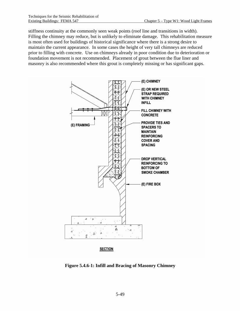
Techniques for the Seismic Rehabilitation of Existing Buildings: FEMA 547 Chapter 5 – Type W1: Wood Light Frames
5-49
stiffness continuity at the commonly seen weak points (roof line and transitions in width). Filling the chimney may reduce, but is unlikely to eliminate damage. This rehabilitation measure is most often used for buildings of historical significance where there is a strong desire to maintain the current appearance. In some cases the height of very tall chimneys are reduced prior to filling with concrete. Use on chimneys already in poor condition due to deterioration or foundation movement is not recommended. Placement of grout between the flue liner and masonry is also recommended where this grout is completely missing or has significant gaps.
Figure 5.4.6-1: Infill and Bracing of Masonry Chimney

Techniques for the Seismic Rehabilitation of Existing Buildings: FEMA 547 Chapter 5 – Type W1: Wood Light Frames
5-50
Figure 5.4.6-2 illustrates anchorage of an exterior masonry chimney to floor, roof and ceiling framing. This detail is an adaptation of prescriptive information for new construction in the IBC (ICC, 2003a) and the Masonry Fireplace and Chimney Handbook (Amrhein, 1995). The steel strap is intended to keep the chimney from falling away from the building. In order to do this, the strap must be anchored into existing floor and roof framing with a capacity and load path adequate to resist forces from the chimney. Anchorage to wall studs or a single framing member will not accomplish this. It is often difficult and disruptive to anchor far enough into the building to develop required capacity. Figure 5.4.6-2 is intended for small to medium size chimneys common in single-family residences. Large and irregularly configured chimneys require additional consideration.
Design Considerations Research basis: No research applicable to these rehabilitation techniques has been identified. Earthquake reconnaissance reports provide a limited record of earthquake performance of rehabilitation techniques. Cautions: Some in the earthquake engineering community recommend against rehabilitation measures involving unreinforced masonry chimney anchorage to light-frame buildings on the basis that the anchorage is unlikely to eliminate earthquake damage. Indeed, damage and occasionally partial collapse of anchored chimneys have been seen in past earthquakes. The inherent difference in stiffness between masonry chimneys and fireplaces and light-frame construction is a likely contributor, along with widely varying adequacy of anchorage detailing and installation. The potential hazard posed by an unreinforced and/or unanchored chimney and the ability to reduce the hazard using one or more rehabilitation techniques need to be weighed for each building under consideration. Other practical measures to reduce life-safety threats due to unreinforced chimneys include limiting activities (interior as well as exterior) in the immediate vicinity of the chimney and fireplace and placing wood structural panel sheets on ceiling rafters alongside the chimney to slow down any portions falling to the interior (ABAG, 2005). Variations in existing chimney conditions: Either careful evaluation of the existing chimney construction or worst-case assumptions regarding construction are suggested. Even when chimneys would have been required by buildings codes to be grouted and reinforced, it is common to find chimneys ungrouted, poorly grouted and unreinforced. Foundations: In areas of poor soils, the weight of the chimney and firebox can result in higher settlement, and sometimes differential settlement, leading to leaning. Foundation problems need to be resolved before other rehabilitation measures are considered.
Detailing Considerations Anchorage of a strap or other tie to an existing masonry chimney should be avoided where possible and otherwise approached with caution. Expansion anchors cause splitting tensile stresses that can result in cracking of the masonry. Adhesive anchors change properties under elevated temperatures that might be experienced during use of the chimney.

Techniques for the Seismic Rehabilitation of Existing Buildings: FEMA 547 Chapter 5 – Type W1: Wood Light Frames
5-51
Figure 5.4.6-2A: Bracing of Masonry Chimney
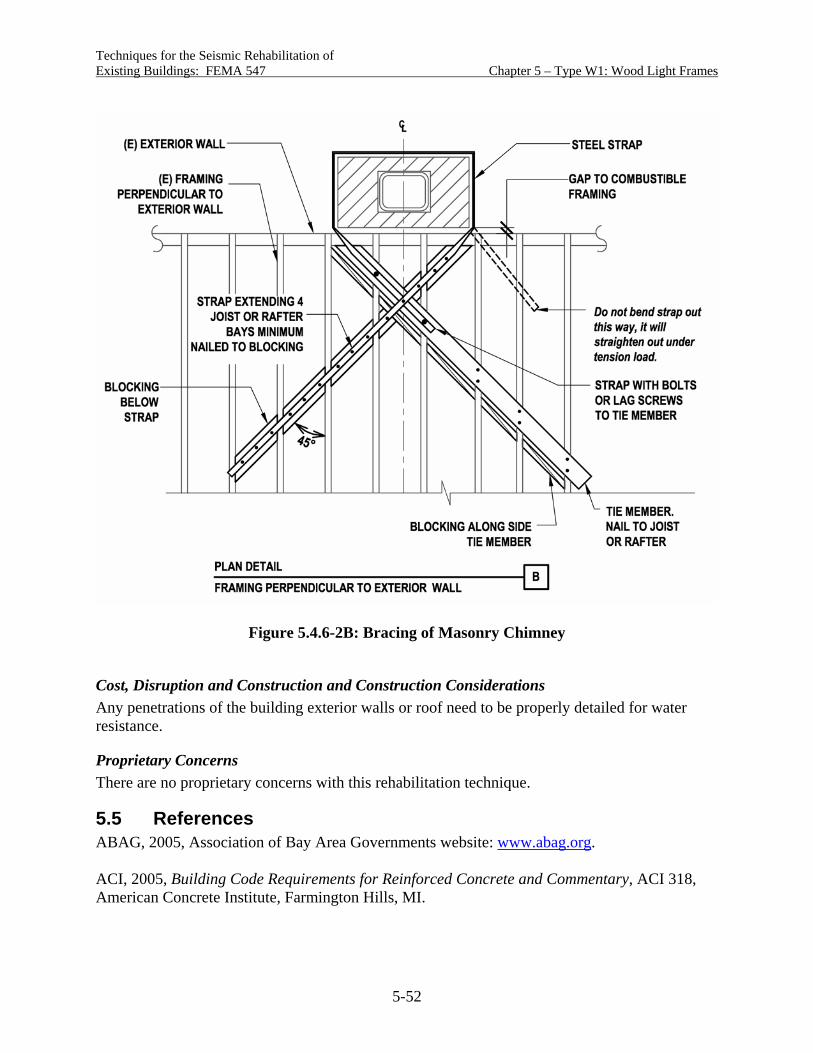
Techniques for the Seismic Rehabilitation of Existing Buildings: FEMA 547 Chapter 5 – Type W1: Wood Light Frames
5-52
Figure 5.4.6-2B: Bracing of Masonry Chimney
Cost, Disruption and Construction and Construction Considerations Any penetrations of the building exterior walls or roof need to be properly detailed for water resistance.
Proprietary Concerns There are no proprietary concerns with this rehabilitation technique.
5.5 References ABAG, 2005, Association of Bay Area Governments website: www.abag.org. ACI, 2005, Building Code Requirements for Reinforced Concrete and Commentary, ACI 318, American Concrete Institute, Farmington Hills, MI.

Techniques for the Seismic Rehabilitation of Existing Buildings: FEMA 547 Chapter 5 – Type W1: Wood Light Frames
5-53
AF&PA, 2003, Plank and Beam Framing for Residential Buildings, American Forest & Paper Association, Washington, D.C. AF&PA, 2005a, National Design Specification for Wood Construction, ASD/LRFD, American Forest & Paper Association, Washington, D.C. AF&PA, 2005b, Special Design Provisions for Wind and Seismic, ASD/LRFD, American Forest & Paper Association, Washington, D.C. Amrhein, J., 1995, Residential Masonry Fireplace and Chimney Handbook, Second Edition, Masonry Institute of America, Torrance, CA. APA, 1999a, Wood Structural Panel Shear Walls (Research Report 154), APA The Engineered Wood Association, Tacoma, WA. APA, 1999b, Research Report 158, Preliminary Testing of Wood Structural Panel Shear walls Under Cyclic (Reversed) Loading, APA The Engineered Wood Association, Tacoma, WA. APA, 2003, Shear Wall Lumber Framing: Double 2x’s vs. Single 3x’s at Adjoining Panel Edges (Report T2003-22), APA The Engineered Wood Association, Tacoma, WA. ATC, 1976, A Methodology for Seismic Design and Construction of Single-Family Dwellings, ATC 4, Applied Technology Council, Redwood City, CA. ATC, 1995, Cyclic Testing of Narrow Plywood Shear Walls, ATC R-1, Applied Technology Council, Redwood City, CA. Chai, Y.H., T.C. Hutchinson and S. M. Vukazich, 2002, Seismic Behavior of Level and Stepped Cripple Walls, CUREE Publication No. W-17, Consortium of Universities for Research in Earthquake Engineering, Richmond, CA. City of Los Angeles, 2002, “Voluntary Earthquake Hazard Reduction in Existing Hillside Buildings (Chapter 94),” City of Los Angeles Building Code, Los Angeles, CA. City of Los Angeles, 2000, Reconstruction and Replacement of Earthquake Damage Chimneys (P/BC 2001-70), City of Los Angeles Department of Building and Safety, Los Angeles, CA. City of Los Angeles & SEAOSC, 1996, Findings and Recommendations of the Hillside Buildings Subcommittee of the City of Los Angeles Department of Building and Safety & Structural Engineers Association of Southern California Task Force on Evaluating Damage From the Northridge Earthquake, Final Report, City of Los Angeles, CA. Cobeen, K., 2004, “Recent Developments in the Seismic Design and Construction of Woodframe Buildings,” Earthquake Engineering From Engineering Seismology to Performance Based Engineering, CRC Press, Boca Raton, FL.
Techniques for the Seismic Rehabilitation of Existing Buildings: FEMA 547 Chapter 5 – Type W1: Wood Light Frames
5-54
Cobeen, K., J. Russell and J.D. Dolan, 2004, Recommendations for Earthquake Resistance in the Design and Construction of Woodframe Buildings, CUREE Publication No. W-30b, Consortium of Universities for Research in Earthquake Engineering, Richmond, CA. Dolan, J.D., 2003, “Wood Structures,” Earthquake Engineering Handbook,” CRC Press, Boca Raton, FL. EERI, 1996, “Supplement C to Volume II - Northridge Earthquake of January 17, 1994 Reconnaissance Report Volume 2,” Earthquake Spectra, Earthquake Engineering Research Institute, Oakland, CA. FEMA, 2000, Prestandard and Commentary for the Seismic Rehabilitation of Buildings, FEMA 356, Federal Emergency Management Agency, Washington, D.C. FEMA, 2003, NEHRP Provisions for New Buildings and Other Structures, FEMA 450, Federal Emergency Management Agency, Washington, D.C. Gatto, K. and C.M. Uang, 2002, Cyclic Response of Woodframe Shearwalls: Loading Protocol and Rate of Loading Rate Effects, CUREE Publication No. W-13, Consortium of Universities for Research in Earthquake Engineering, Richmond, CA. Heine, C., 1997, Effect of Overturning Restraint on the Performance of Fully Sheathed and Perforated Timber Framed Shear Walls, Virginia Polytechnic Institute and State University, Blacksburg, VA. ICBO, 1997a, Uniform Building Code, International Conference of Building Officials, Whittier, CA. ICBO, 1997b, Uniform Code for Building Conservation, International Conference of Building Officials, Whittier, CA. ICBO, 2001, Guidelines for the Seismic Retrofit of Existing Buildings, International Conference of Building Officials, Whittier, CA. ICC, 2003a, International Building Code, International Code Conference, Country Club Hills, IL. ICC, 2003b, International Existing Building Code, International Code Conference, Country Club Hills, IL. ICC, 2005, 2003 International Existing Building Code (IEBC) Commentary, International Code Conference, Country Club Hills, IL. Isoda, H., B. Folz, and A. Filiatrault, 2002, Seismic Modeling of Woodframe Index Buildings, CUREE Publication No.W-12, Consortium of Universities for Research in Earthquake Engineering, Richmond, CA.

Techniques for the Seismic Rehabilitation of Existing Buildings: FEMA 547 Chapter 5 – Type W1: Wood Light Frames
5-55
Kolba, A., 2000, The Behavior of Wood Shear Walls Designed Using the Diekmann’s Method and Subjected to Static In-plane Loading, Marquette University, Milwaukee, WI. Mahaney, J. A. and B. E. Kehoe, 2002, Anchorage of Woodframe Buildings, Laboratory Testing Report, CUREE Publication No. W-14, Consortium of Universities for Research in Earthquake Engineering, Richmond, CA. Mosalam, K., C. Machado, K-U. Gliniorz, C. Naito, E. Kunkel and S. Mahin, 2002, Seismic Evaluation of an Asymmetric Three-Story Woodframe Building, CUREE Publication No. W-19, Consortium of Universities for Research in Earthquake Engineering, Richmond, CA. OES and FEMA, 2000, Guidelines to Strengthen and Retrofit Your Home Before the Next Earthquake, State of California Governor’s Office of Emergency Services, Sacramento, CA and Federal Emergency Management Agency, Washington, D.C. Pardoen, G., A. Waltman, R. Kazanjy, E. Freund, and C. Hamilton, 2003, Testing and Analysis of One-Story and Two-Story Walls Under Cyclic Loading, CUREE Publication No. W-25, CUREE, Richmond, CA. Salenikovich, A., 2000, The Racking Performance of Light-Frame Shear Walls, Virginia Polytechnic Institute and State University, Department of Wood Science and Forest Products, Blacksburg, VA. SEAOC (Structural Engineers Association of California), 1999, Recommended Lateral Force Requirements and Commentary, Seventh Edition, Structural Engineers Association of California, Sacramento, CA. von Winterfeldt, D., N. Roselund, and A. Kitsuse, 2000, Framing Earthquake Retrofitting Decisions: The Case of Hillside Homes in Los Angeles, PEER Report 2000-03, Pacific Engineering Research Center, Richmond, CA. Xiao Y. and L. Xie, 2002, Seismic Behavior of Base-Level Diaphragm Anchorage of Hillside Buildings, CUREE Publication No. W-24, Consortium of Universities for Research in Earthquake Engineering, Richmond, CA.

Techniques for the Seismic Rehabilitation of Chapter 6 - Type W1A: Multistory, Existing Buildings: FEMA 547 Multi-Unit Residential Woodframes
6-1
Chapter 6 - Building Type W1A: Multistory, Multi-Unit Residential Woodframes
6.1 Description of the Model Building Type Building Type W1A is similar to Building Type W1 in use of woodframe wall, floor and roof construction, but includes large multi-family, multistory buildings. In W1A buildings, second and higher stories are almost exclusively residential use, while the first story can include any combination of parking, common areas, storage, and residential units. Post and beam framing often replaces bearing walls in non-residential areas. Multi-family residential buildings with commercial space at the first story are included in building Type W1A due to similar building characteristics. Lateral forces in W1A buildings are primarily resisted by wood diaphragms and shear walls. Figure 6.1-1 provides an illustration of this building type.
Figure 6.1-1: Building Type W1A: Multistory Multi-Unit Residential Woodframes
This chapter addresses W1A buildings where the first story walls are of woodframe construction. This includes both multistory woodframe buildings supported at grade and the multistory woodframe portion of buildings with concrete or masonry walls at one or more lower stories. The stories with concrete or masonry walls represent building types other than W1A, and they are addressed by other chapters in this document.
Techniques for the Seismic Rehabilitation of Chapter 6 - Type W1A: Multistory, Existing Buildings: FEMA 547 Multi-Unit Residential Woodframes
6-2
Variations in the W1A building type can include a combination of multi-family residential use and the hillside building configuration discussed in Section 5.4.5. For this combination, rehabilitation measures from this chapter and Section 5.4.5 are applicable.
Design Practice W1A buildings including apartment and condominium buildings, residential hotels, motels, and residential use over commercial space are very common in the current building stock, with some dating back to the early 1900s or earlier. While many W1A buildings constructed in the 1980s and later will have had a partially or fully engineered design, the majority of older W1A buildings will not. Case studies of California tuckunder buildings constructed in the 1970s (Schierle, 2001) indicate that a check of first-story walls for in-plane shear capacity was common, shear wall overturning was not considered, and bracing of upper stories commonly relied on prescriptive construction provisions. Steinbrugge, Bush and Johnson (1996) chronicled changes in California design practice of multi-family residential buildings since the 1960s. In some regions, these buildings are currently constructed using prescriptive codes.
Walls Wall bracing materials include the same range discussed for W1 buildings. Checks of first floor shear capacity in California tuckunder apartment buildings led to the use of wood structural panel sheathing without overturning anchorage in some first story walls in the 1960s and 1970s. Cripple walls, also discussed with the W1 building type, are common in W1A buildings up until the 1950s.
Floor and Roof Diaphragms Floor and roof diaphragms include the same materials as the W1 building type, however plank and beam systems are rare in W1A buildings.
Foundations Foundation types and issues for W1 buildings are also applicable to W1A buildings. Of note, the gravity dead and live loads in W1A buildings can be significantly higher than in W1 buildings.
Identification and Performance of Vulnerable Buildings Several W1A building vulnerable configurations have become prominent in literature and discussion because of collapses or near collapses of lowest woodframe stories in the Loma Prieta and Northridge earthquakes. While these vulnerabilities are important for the W1A building type, they are not the only deficiencies that require consideration. See Section 6.3 for a systematic discussion of seismic deficiencies. The discussion of these prominent vulnerable configurations requires a common understanding of terminology. In addition, a brief review is provided of documents that discuss performance, identification and rehabilitation provisions for vulnerable stories in W1A buildings. W1A buildings, regardless of design approach, gain much of their strength and stiffness from bracing and finish materials on exterior walls and interior walls between and within residential units. This is true whether or not these walls are identified as shear walls. Where residential use

Techniques for the Seismic Rehabilitation of Chapter 6 - Type W1A: Multistory, Existing Buildings: FEMA 547 Multi-Unit Residential Woodframes
6-3
occurs in multiple stories, it is common for residential unit layouts to be similar at each story, providing substantially uniform story strength and stiffness. Where the lowest story includes uses such as parking, common areas, commercial use, etc., the amount of exterior and interior wall is reduced, often resulting in significantly reduced story strength and stiffness. At the same time, the lowest story experiences the highest earthquake demands. The terms weak story and soft story are used for this condition in which a story has less strength or stiffness than the story above. Concentration of deformation demand is understood to occur in a soft story. Inadequate strength and story failure may occur in a weak story. These would be identified as global strength and stiffness deficiencies for purposes of this chapter. Exact definitions of what constitutes a soft or weak story vary, as do opinions as to when soft and weak stories become vulnerable enough to recommend rehabilitation. Little research is available to assist in identifying when these configurations pose a hazard to life. Where parking occurs in all or a portion of the lowest woodframe story, significant openings in the exterior walls are generally provided in order to allow access to the parking. Often there is little or no interior wall in the parking area. The term tuckunder parking (named due to the parking being tucked under the residential units) is used for this type of building configuration. Tuckunder parking buildings with woodframe walls at the parking story will often have a soft story and a weak story. Occasionally, parking only exists in a very small portion of the building plan area, and it does not significantly affect the story. An open front building occurs when at any story level there is little or no bracing in one or more exterior walls. The term open front is a misnomer in that the open exterior wall can occur at any side of the building. Woodframe buildings are generally considered to have flexible diaphragms, and as a result bracing elements are generally provided at or near each edge of the diaphragm, most often at exterior walls. When an open front occurs, the diaphragm is required to transmit forces to other wall lines by rotation, creating torsional building behavior. This behavior is particularly critical when an exterior wall is provided at upper stories but discontinued in the first woodframe story, as this creates a significant discontinuity in the load path at the lowest story. Open front buildings often have tuckunder parking, but can also have commercial and other uses. Open front buildings will often but not always also have soft and weak stories at the open front story. Addition of vertical elements at the open front is the most direct rehabilitation approach to open front buildings. In buildings studied to date, capacities in the direction perpendicular to the open front have also been significantly lower that required by current codes and may also require rehabilitation. What the terms soft story, weak story, tuckunder building and open front building all have in common is that they are identifying buildings that have potentially vulnerable stories due to deficient global or local strength or stiffness. In most cases, the vulnerable story is the lowest woodframed story. Appendix Chapter 4 of the International Existing Building Code (IEBC) (ICC, 2003b) and Chapter 4 of the Guidelines for Structural Rehabilitation of Existing Buildings (GSREB) (ICBO, 2001) contain identical provisions for hazard reduction in W1A buildings. These provisions identify a broad range of multistory woodframe buildings as vulnerable based on:

Techniques for the Seismic Rehabilitation of Chapter 6 - Type W1A: Multistory, Existing Buildings: FEMA 547 Multi-Unit Residential Woodframes
6-4
Open front conditions (defined by IEBC as diaphragm cantilever in excess of that
permitted by the applicable building code) A weak wall line (defined by IEBC as story strength less than 80% of the strength of the
story above), or A soft wall line (defined by IEBC as not meeting story drift limits)
The IEBC provisions require evaluation and retrofit, including resisting elements from the diaphragm above the soft, weak, or open front story to the foundation-soil interface. Design is to be in accordance with the current building code except use of 75% of the code base shear is permitted. Specific rehabilitation measures are not detailed (with the exception of a prescriptive rehabilitation for limited building configurations); however, additional requirements for shear wall rehabilitation are included. The IEBC evaluation provisions create the challenge of calculating strength and stiffness for a variety of current and archaic finish materials not generally considered to be part of the lateral force-resisting system. Some guidance on strength and stiffness can be found in FEMA 356 (FEMA, 2000) and the AF&PA Wind and Seismic Supplement (AF&PA, 2005). Focus on the vulnerable first story may be lost in the calculation process. The IEBC also creates the challenge of identifying a wide range of buildings as potentially vulnerable, going well beyond open front and tuckunder configurations observed to be vulnerable to date. No guidance is given in judging relative hazard. If using IEBC Appendix Chapter 4, a commentary to the GSREB (ICC, 2005a) and ICC proposed changes (ICC, 2005b) are important additions. The City of San Jose has developed several documents that assist in identification of vulnerable W1A buildings. The Apartment Owner’s Guide to Earthquake Safety (Vukazich, 1998) uses a procedure based on ATC–21 rapid screening provisions in a broad approach to identifying vulnerable buildings and suggests shear wall enhancement and addition of steel moment frames as primary rehabilitation measures. Practical Solutions for Improving the Seismic Performance of Buildings with Tuckunder Parking (Lizundia and Holmes, 2000) illustrates rehabilitation techniques for three model building types, primarily using shear wall enhancement and steel moment frames. Rehabilitation measures address both life-safety and limited down time objectives. The focus of life safety measures is the first woodframed story. Work for limited down time objectives extends into upper stories. A joint task force of the City of Los Angeles Department of Building Safety and the Structural Engineers Association of Southern California prepared the report Wood Frame Construction Report and Recommendations (City of Los Angeles & SEAOSC, 1994), which contains a series of observations and recommendations for multi-family residential construction based on performance in the Northridge earthquake. Issues include
Poor performance of gypsum wallboard and stucco bracing, attributed in part to high values given to these materials in past Los Angeles codes,
Poor performance of plywood shear walls, attributed to core gaps (gaps in the center ply of three-ply plywood) and slender walls,
Poor performance of tie-downs, attributed to design and installation problems, and
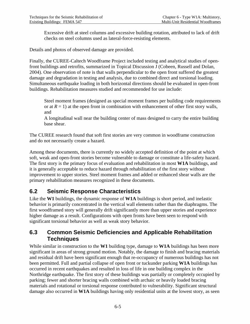
Techniques for the Seismic Rehabilitation of Chapter 6 - Type W1A: Multistory, Existing Buildings: FEMA 547 Multi-Unit Residential Woodframes
6-5
Excessive drift at steel columns and excessive building rotation, attributed to lack of drift checks on steel columns used as lateral-force-resisting elements.
Details and photos of observed damage are provided. Finally, the CUREE-Caltech Woodframe Project included testing and analytical studies of open-front buildings and retrofits, summarized in Topical Discussion J (Cobeen, Russell and Dolan, 2004). One observation of note is that walls perpendicular to the open front suffered the greatest damage and degradation in testing and analysis, due to combined direct and torsional loading. Simultaneous earthquake loading in both horizontal directions should be evaluated in open-front buildings. Rehabilitation measures studied and recommended for use include:
Steel moment frames (designed as special moment frames per building code requirements or at R = 1) at the open front in combination with enhancement of other first story walls, and
A longitudinal wall near the building center of mass designed to carry the entire building base shear.
The CUREE research found that soft first stories are very common in woodframe construction and do not necessarily create a hazard. Among these documents, there is currently no widely accepted definition of the point at which soft, weak and open-front stories become vulnerable to damage or constitute a life-safety hazard. The first story is the primary focus of evaluation and rehabilitation in most W1A buildings, and it is generally acceptable to reduce hazard through rehabilitation of the first story without improvement to upper stories. Steel moment frames and added or enhanced shear walls are the primary rehabilitation measures recognized in these documents.
6.2 Seismic Response Characteristics Like the W1 buildings, the dynamic response of W1A buildings is short period, and inelastic behavior is primarily concentrated in the vertical wall elements rather than the diaphragms. The first woodframed story will generally drift significantly more than upper stories and experience higher damage as a result. Configurations with open fronts have been seen to respond with significant torsional behavior as well as weak story behavior.
6.3 Common Seismic Deficiencies and Applicable Rehabilitation Techniques
While similar in construction to the W1 building type, damage to W1A buildings has been more significant in areas of strong ground motion. Notably, the damage to finish and bracing materials and residual drift have been significant enough that re-occupancy of numerous buildings has not been permitted. Full and partial collapse of open front or tuckunder parking W1A buildings has occurred in recent earthquakes and resulted in loss of life in one building complex in the Northridge earthquake. The first story of these buildings was partially or completely occupied by parking; fewer and shorter bracing walls combined with archaic or heavily loaded bracing materials and rotational or torsional response contributed to vulnerability. Significant structural damage also occurred in W1A buildings having only residential units at the lowest story, as seen

Techniques for the Seismic Rehabilitation of Chapter 6 - Type W1A: Multistory, Existing Buildings: FEMA 547 Multi-Unit Residential Woodframes
6-6
in Schierle (2001) Case Study 10, a three story residential building constructed in the early 1960s and braced with stucco and plaster over gypsum lath. See below for general discussion and Table 6.3-1 for a detailed compilation of common seismic deficiencies and rehabilitation techniques for Building Type W1A.
Global Strength and Stiffness Global strength and stiffness are of particular concern in the first story of W1A buildings and have contributed significantly to damage in past earthquakes, sometimes accentuated by open fronts. Rehabilitation measures for global strength and stiffness include adding new vertical elements and enhancing existing elements. Common added elements are steel moment frames and added or enhanced shear walls. Steel braced frames may be added, but are not common in W1A buildings, since the brace would restrict access for parking or other uses.
Configuration Although most common in W1 buildings, some W1A buildings have missing or inadequately braced cripple walls. See Chapter 5 for rehabilitation techniques. Where W1A buildings are of large plan area, it may be necessary to add interior cripple walls and new interior foundations. It is common to enhance or add cripple walls in W1 buildings without specifically accounting for overturning behavior in the stories above. Caution should be exercised in taking this approach with W1A buildings due to the larger size and weight. In addition, where uplift anchorage is being provided in stories above, the load path must be carried through the cripple wall to the foundation. Torsional irregularities due to open fronts are prevalent and of significant concern in W1A buildings. Open fronts are often in the first story, and they combine with weak and soft story behavior. Where open fronts occur in tuckunder buildings, continued use of the first story parking often dictates that this deficiency be mitigated by the addition of steel moment frames. Wood shear walls and steel braced frames are alternate measures. It is important that walls perpendicular to the open front also be evaluated and enhanced, as these can be significantly deficient also.
Load Path Adequate load path connection is a concern for W1A buildings, particularly so in first stories, which are likely to experience the majority of force and deformation demands. Many W1A buildings constructed in California in the 1960s and 1970s used wood structural panel sheathing in the first story, but did not have overturning detailing. Testing suggests that significant reductions in shear wall strength and stiffness can occur when overturning detailing is not provided. Likewise, many W1A and W2 buildings are braced with diagonal lumber sheathing without overturning anchorage. Addition of overturning anchorage to these buildings could potentially greatly improve performance. Related to the overturning load path, in W1A buildings where upper story shear walls are discontinued in lower stories, beams and posts providing vertical support at shear wall ends are potentially vulnerable. Instances of rehabilitation of members supporting shear walls in W1, W1A and W2 buildings are very limited to date. This is because W1A building retrofits have focused on first story vulnerability, because earthquake damage to date has not shown this to be
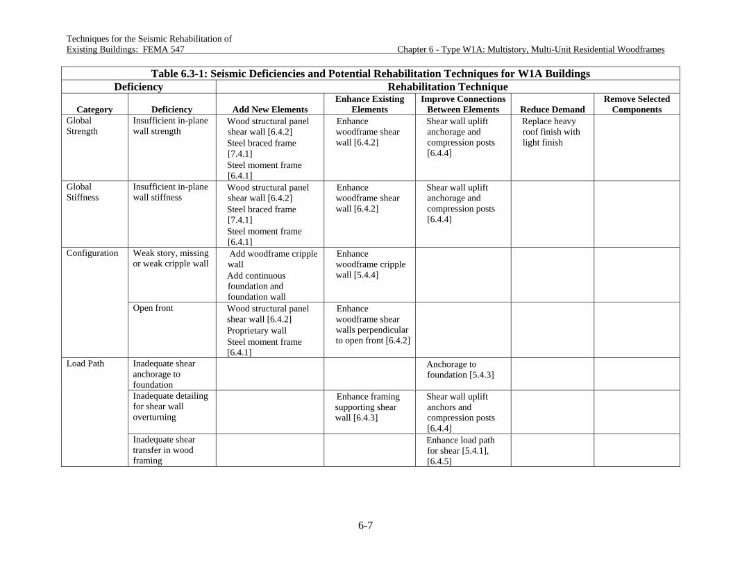
Techniques for the Seismic Rehabilitation of Existing Buildings: FEMA 547 Chapter 6 - Type W1A: Multistory, Multi-Unit Residential Woodframes
6-7
Table 6.3-1: Seismic Deficiencies and Potential Rehabilitation Techniques for W1A Buildings Deficiency Rehabilitation Technique
Category Deficiency Add New Elements Enhance Existing
Elements Improve Connections
Between Elements Reduce Demand Remove Selected
Components Global Strength
Insufficient in-plane wall strength
Wood structural panel shear wall [6.4.2]
Steel braced frame [7.4.1]
Steel moment frame [6.4.1]
Enhance woodframe shear wall [6.4.2]
Shear wall uplift anchorage and compression posts [6.4.4]
Replace heavy roof finish with light finish
Global Stiffness
Insufficient in-plane wall stiffness
Wood structural panel shear wall [6.4.2]
Steel braced frame [7.4.1]
Steel moment frame [6.4.1]
Enhance woodframe shear wall [6.4.2]
Shear wall uplift anchorage and compression posts [6.4.4]
Weak story, missing or weak cripple wall
Add woodframe cripple wall
Add continuous foundation and foundation wall
Enhance woodframe cripple wall [5.4.4]
Configuration
Open front Wood structural panel shear wall [6.4.2]
Proprietary wall Steel moment frame
[6.4.1]
Enhance woodframe shear walls perpendicular to open front [6.4.2]
Inadequate shear anchorage to foundation
Anchorage to foundation [5.4.3]
Inadequate detailing for shear wall overturning
Enhance framing supporting shear wall [6.4.3]
Shear wall uplift anchors and compression posts [6.4.4]
Load Path
Inadequate shear transfer in wood framing
Enhance load path for shear [5.4.1], [6.4.5]

Techniques for the Seismic Rehabilitation of Existing Buildings: FEMA 547 Chapter 6 - Type W1A: Multistory, Multi-Unit Residential Woodframes
6-8
Table 6.3-1: Seismic Deficiencies and Potential Rehabilitation Techniques for W1A Buildings Deficiency Rehabilitation Technique
Category Deficiency Add New Elements Enhance Existing
Elements Improve Connections
Between Elements Reduce Demand Remove Selected
Components Load Path (continued)
Inadequate collectors to shear walls
Enhance existing collector
Add collector [6.4.5], [7.4.2]
Component Detailing
Unreinforced & unbraced chimney
Infill chimney [5.4.6]
Brace chimney [5.4.6]
Reduce unsupported chimney height [5.4.6]
Remove chimney [5.4.6]
Inadequate in-plane strength and/or stiffness
Enhanced diaphragm [22.2.1]
Replace heavy roof finish with light finish
Inadequate chord capacity
Enhance chord members and connections [22.2.2]
Excessive stresses at openings and irregularities
Enhance diaphragm detailing
Diaphragms
Re-entrant corners
Enhance diaphragm detailing
Foundations See Chapter 23 [ ] Numbers noted in brackets refer to sections containing detailed descriptions of rehabilitation techniques.

Techniques for the Seismic Rehabilitation of Chapter 6 - Type W1A: Multistory, Existing Buildings: FEMA 547 Multi-Unit Residential Woodframes
6-9
a critical weakness in woodframe construction and because rehabilitation of these supports can be difficult and expensive. Shear transfer into and out of shear walls and other vertical elements must be adequate in order for the vertical element to fully contribute to building performance. While systematic evaluation may identify insufficient shear transfer at any story, shear transfer in first story walls is of particular concern due to reductions in the amount of shear wall and increases in unit loads. As in the W1 building, adequate anchorage to the foundation is a high priority rehabilitation measure.
Component Detailing Damage to unreinforced masonry chimneys has occurred in practically every earthquake to date. Approaches to rehabilitation include bracing, reducing height, infilling or removing. See Chapter 5.
Diaphragm Deficiencies Although diaphragm deficiencies have not been seen as a significant contributor to damage to date, systematic evaluation can identify this as a deficiency. Rehabilitation measures include enhancing existing diaphragms through added fastening, blocking, and overlaying. Detailing can also be added at openings and re-entrant corners. See Chapter 22.
6.4 Detailed Description of Techniques Primarily Associated with This Building Type
6.4.1 Add Steel Moment Frame
Deficiency Addressed by Rehabilitation Technique This rehabilitation technique addresses insufficient global or local strength or stiffness through the addition of steel moment frames. This rehabilitation technique is particularly beneficial in buildings with open fronts due to tuckunder parking, because the use of moment frames permits continued use of parking stalls. It is similarly beneficial for other buildings where continued use does not allow the addition of shear walls.
Description of the Rehabilitation Technique This rehabilitation technique most commonly involves the addition of steel moment frames immediately adjacent to existing beams and columns, at or near a first story open front. Moment frames are less commonly added in other locations and in stories above the first story. Figure 6.4.1-1A illustrates an elevation of a typical single-bent steel moment frame added immediately in front of existing beams and columns. Such frames might be added at every second or third framing bay across the building front. Moment frames can be brought to the job site in a complete beam plus two-column bent or in two L-shaped pieces with a field-bolted splice at beam mid-span. The use of two L-shaped pieces allows the critical beam to column connections to be welded in the fabrication shop with better access and quality control. The height required to tilt the frame into place is the factor most commonly governing whether frames are fabricated in one or two pieces. A new foundation will often be required to support the moment frame. This can either be an isolated footing at each end or a continuous footing.

Techniques for the Seismic Rehabilitation of Chapter 6 - Type W1A: Multistory, Existing Buildings: FEMA 547 Multi-Unit Residential Woodframes
6-10
Figure 6.4.1-1A: Elevation of Steel Moment Frame in W1A Building Footing placement will generally require the shoring of the upper stories and full or partial removal of existing footings. Transfer of earthquake load from the diaphragm above to the steel moment frame will commonly involve a collector that runs the full length of the open front and a series of connections from the collector to the steel moment frame. Figures 6.4.1-1B, 6.4.1-1C and 6.4.1-1D illustrate possible connections. See discussion of collectors and shear transfer in the Design Considerations section. A number of detailing considerations discussed in Section 5.4.1 are applicable to frame connection to the existing wood building. In particular, detailing must accommodate shrinkage and possible swelling of wood, and alternate fasteners to existing sheathing may be needed. This rehabilitation measure is not intended to address systems of steel columns cantilevered from the foundation without moment connections to a beam at the top. This cantilevered column system should be used with caution due to the difficulty of quantifying and limiting the many potential sources of rotation and deflection and to inadequate knowledge of post-elastic system behavior.

Techniques for the Seismic Rehabilitation of Chapter 6 - Type W1A: Multistory, Existing Buildings: FEMA 547 Multi-Unit Residential Woodframes
6-11
Figure 6.4.1-1B: Shear Transfer Between Moment Frame Beam and Diaphragm
Design Considerations Research basis: Research specifically addressing steel moment frames in woodframe buildings includes: Seismic Evaluation of an Asymmetric Three-Story Woodframe Building (Mosalam et al., 2002) and Improving Loss Estimation for Woodframe Buildings (Porter et al., 2002). Results from these studies are also discussed in Cobeen, Russell, and Dolan (2004). Moment frame design criteria: Chapter 8 of this document addresses steel moment frame rehabilitation in buildings where steel moment frames are the primary lateral force-resisting system. In contrast, when used for rehabilitation of W1A buildings, steel moment frames will generally only be used in one story and along one building line. The response modification factor of the woodframe building above makes use of either an ordinary or intermediate moment frame a logical choice for the first story of a multistory W1A building. Limitations addressing use in light-frame buildings have been in a state of flux. The most current seismic design provisions, ASCE 7-05 (ASCE, 2005) and AISC Seismic (2005), permit:
Single story ordinary moment frames (OMF) for new buildings in Seismic Design Category (SDC) D and E, to a height of 65 feet, provided dead load tributary to the roof does not exceed 20 psf and tributary wall dead load does not exceed 20 psf

Techniques for the Seismic Rehabilitation of Chapter 6 - Type W1A: Multistory, Existing Buildings: FEMA 547 Multi-Unit Residential Woodframes
6-12
Figure 6.4.1-1C: Shear Transfer from Moment Frame Beam to Collector
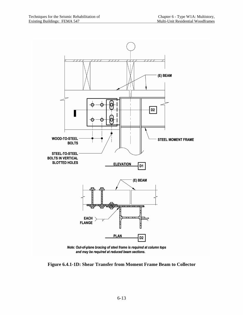
Techniques for the Seismic Rehabilitation of Chapter 6 - Type W1A: Multistory, Existing Buildings: FEMA 547 Multi-Unit Residential Woodframes
6-13
Figure 6.4.1-1D: Shear Transfer from Moment Frame Beam to Collector

Techniques for the Seismic Rehabilitation of Chapter 6 - Type W1A: Multistory, Existing Buildings: FEMA 547 Multi-Unit Residential Woodframes
6-14
OMFs for new buildings in SDC D and E in light frame construction up to a height of
35 feet, with roof and floor dead load to tributary to the frame not exceeding 35 psf and wall dead load tributary to the frame not exceeding 20 psf
Intermediate moment frames (IMFs) in SDC D up to a height of 35 feet IMFs in SDC E up to a height of 35 feet with tributary floor and roof dead load not
exceeding 35 psf and tributary wall dead load not exceeding 20 psf A three-story W1A building will generally just meet the height and weight limits to allow use of an OMF. This allows the choice of OMF, IMF or special moment frame (SMF). While SMFs are always acceptable, the response modification factor must not be taken as greater than for the lateral force-resisting system above (typically wood shear wall), and use of pre-qualified welded joints may require use of steel beam and column sizes larger than acceptable. Because the limitations for use of moment frames in light-frame construction have been in a state of flux, a number of organizations and jurisdictions have developed local guidance for design and rehabilitation. Among these are:
Provisions used by the City of Santa Monica with the response modification factor set as one (used in CUREE Woodframe Project research)
Draft guidelines by the SEAOSC Steel Ad Hoc Committee (SEAOC, 2002) addressing up to two-story buildings and recommended reduced drift and quality assurance measures
Draft procedures by the ICC Peninsula Chapter (2004) addressing design procedures and quality assurance measures
The need for these guidelines in addition to the latest design standards requires review. One of the recommendations made in the guidelines is that moment frame drift be limited to less than required by code in recognition of the lesser ductility of the connections. Shear transfer and collector detailing: Provision of adequate strength and stiffness for shear transfer from the building wood framing into the steel moment frame is key to improved building performance. Where the shear transfer detail allows significant slip, undesirable building deflection will occur. This was observed to be a significant issue in the CUREE-Caltech Woodframe Project testing of moment frames (Mosalam et al., 2002) (Cobeen, Russell, and Dolan, 2004). Figure 6.4.1-1C3 illustrates the shear transfer detail used in a simplified moment frame. The shear transfer was designed using tributary seismic forces, but without consideration of overstrength or the force that could be developed by the system. The connection used wood filler pieces and through bolts, and it was intended to reflect common design practice. Excessive slip developed between the wood beam and the filler. At peak capacity, the slip accounted for 40% of the total system drift, and the bolts cut long slots into the beam and fillers. Figure 6.4.1-1C1, based on a Rutherford & Chekene detail for the CUREE testing, shows a shear transfer detail used for the special moment frame tested in the shake table tuckunder building. Two significant differences occur in this detail. First, the shear transfer connection was designed to develop the capacity of the diaphragm above; and second, the wood-to-wood connection was replaced with a lower-slip wood-to-steel connection. Although the forces seen by the frame were

Techniques for the Seismic Rehabilitation of Chapter 6 - Type W1A: Multistory, Existing Buildings: FEMA 547 Multi-Unit Residential Woodframes
6-15
moderate, the connection resulted in less slip, suggesting that better control of building drift would result. Although the first (Figure 6.4.1-1C3) connection could be improved by design using overstrength forces, the second (Figure 6.4.1-1C1) connection approach is recommended. It is further recommended that the approach of using overstrength forces and limiting slip be applied to other shear force transfer connections, including those shown in Figures 6.4.1-1B and 6.4.1-1D. Steel moment frame design and detailing: Design and detailing of steel moment frames used in rehabilitation should be in accordance with the most recent edition of IBC and AISC provisions. Moment frame column bases: Columns in the CUREE testing used base plate details that are commonly considered to provide pinned conditions. This was done to minimize the moment demand put on the foundation, keeping foundation rehabilitation to a minimum, and to keep inelastic behavior in places where performance could be more easily predicted. The column base behavior during testing corresponded well to the assumed near-pinned condition, with little or no deterioration of the base plate connection seen. The use of pinned column base detailing is recommended. Lateral bracing of columns: Bracing at the beam top and bottom flange elevations is required at the moment frame columns. For the CUREE testing, steel angle braces were provided between bottom flange continuity plates and wood floor joists. Lateral bracing of beam flanges: Continuous bracing of the moment frame beam top flange is generally easily accomplished by the addition of a bolted nailer and connection to new or added framing, as shown in Figure 6.4.1-1B. Provisions for SMFs may require the bracing of the beam bottom flange just beyond the plastic hinge zone if bracing was included in prequalification testing. Bracing forces that are easily accommodated in steel construction can be more of a significant detailing issue in woodframe rehabilitation, depending on how far the bracing force is developed into the wood framing system. As a minimum, the brace member and its connection at either end should develop required forces. Addition of moment frames in upper stories: Where moment frames are added in upper stories, provision for a load path to the foundation is required. The load path should be designed using the forces that can develop in the frame using overstrength, force-controlled action, or target displacement approaches.
Detailing Considerations Accommodation of wood shrinkage: Figure 6.4.1-1 details use vertical slotted holes in the steel side plates to accommodate wood shrinkage (or expansion) and possible vertical movement due to deformation of the steel moment frame beam. This approach should be used at any location where steel side plates are placed against wood framing, provided the connection is only intended to transfer horizontal forces. See Section 5.4.1 for further discussion of wood shrinkage issues.

Techniques for the Seismic Rehabilitation of Chapter 6 - Type W1A: Multistory, Existing Buildings: FEMA 547 Multi-Unit Residential Woodframes
6-16
Cost and Disruption Considerations It is very unlikely for the addition of a steel moment frame to be the least expensive or quickest way to rehabilitate for global or local strength or stiffness. The steel moment frame requires the involvement of multiple building trades: fabrication in a steel fabrication shop and site assembly by steel workers, in addition to foundation and framing work at the job site. The addition or enhancement of shear walls will be less expensive. In buildings were the addition of shear walls is not acceptable, however, the addition of a steel moment frame does provide a reasonable and common rehabilitation approach.
Construction Considerations Plumbing, HVAC or electrical lines may be running in the floor framing in the vicinity of steel moment frame locations. Either accommodation in the structural design or relocation of utilities may be necessary. Job site welding of steel members requires adequate access and special ventilation measures in enclosed buildings. Welding of steel members in the vicinity of woodframe construction can be a significant fire hazard and should only be undertaken by experienced welders and only when absolutely necessary. Smoldering droppings from on-site welding and cutting have repeatedly caused structure fires. Welding should always be done by certified welders using approved welding techniques in compliance with building code welding and special inspection requirements.
Proprietary Concerns There are no proprietary concerns with this rehabilitation technique.
6.4.2 Add New or Enhance Existing Wood Shear Wall
Deficiency Addressed by Rehabilitation Technique This rehabilitation technique addresses insufficient global or local strength or stiffness though the addition of or enhancement of vertical elements of the lateral force-resisting system. In W1A buildings, stories with inadequate global first story strength and first story open fronts have been vulnerable in past earthquakes. Rehabilitation of shear walls perpendicular to the open front is often necessary.
Description of the Rehabilitation Technique This rehabilitation technique involves the addition of a shear wall (framing and sheathing) or enhancement of an existing shear wall by the addition of sheathing, the addition of sheathing fastening, or a wood structural panel overlay. Added shear walls: When new shear wall framing and sheathing are being added, the most difficult design issue is mobilizing dead load to resist uplift due to shear wall overturning. Design for transfer of overturning forces to the supporting soils requires an understanding of the existing foundation configuration. Added shear walls can then be located to specifically make use of or avoid existing foundations. Figure 6.4.2-1 shows a shear wall located so that it can use the dead load carried by a building column to resist uplift at the left hand side and an existing bearing wall foundation at the right

Techniques for the Seismic Rehabilitation of Chapter 6 - Type W1A: Multistory, Existing Buildings: FEMA 547 Multi-Unit Residential Woodframes
6-17
Figure 6.4.2-1: Added Shear Wall Supported on Existing Foundation and Slab

Techniques for the Seismic Rehabilitation of Chapter 6 - Type W1A: Multistory, Existing Buildings: FEMA 547 Multi-Unit Residential Woodframes
6-18
hand side. The existing foundations need to be checked for adequate dead load resistance and adequate capacity to resist both up and down forces within material and soil strengths. At the left hand side, the existing column connection to the foundation needs to be capable of picking up the footing and surrounding slab. Use of this detail is limited not only by the adequacy of the foundation for overturning forces, but also the adequacy of the slab for shear anchorage. The slab must be thick enough to allow the installation of expansion bolts or adhesive anchors for anchor bolts. This starts being possible at a slab thickness of about four inches and is best with a slab of five inches or greater. Use of powder-driven fasteners for shear transfer to the slab is not recommended. Testing has found that these anchors fail prematurely under cyclic loads (Mahaney and Kehoe, 2002; and Cobeen, Russell, and Dolan, 2004). Figure 6.4.2-2 shows a shear wall supported on a new strip footing. The new footing runs between and is doweled into existing footings at each end, allowing the dead load of the existing footing to resist overturning. The addition of a new footing allows new anchor bolts to be cast-in, greatly simplifying shear anchorage. It also allows the addition of a curb to help reduce decay exposure in areas like garages that might have water exposure. Figure 6.4.2-3 shows a shear wall added away from any existing footings. A large pad-type footing will be needed to provide enough dead load to resist overturning forces. Enhanced shear walls: Section 5.4.1 provides a detailed discussion of enhancing shear walls by the addition of structural sheathing to walls currently braced with finish materials. This discussion is equally applicable to W1A building, and it is also applicable when it is decided to remove existing wood structural panel sheathing and replace it with new sheathing of higher capacity. Other approaches to enhancing shear wall capacity include the overlaying of new wood structural panel sheathing over existing sheathing and addition of fastening (added nails or staples) to existing sheathing. Figure 6.4.2-4A illustrates the addition of nails to increase shear wall capacity. New nails do not need to be added between every existing nail pair. It is acceptable to space them out to every second or third nail pair, as long as the average over two to three feet meets the needed spacing. It is desirable to distribute added nails as evenly as possible over the height of the wall. Too many nails can reduce performance: additional detailing requirements may be triggered, the wall overstrength will be increased, and demand on anchorages will be increase. Additionally, if not symmetrically placed, added nails can reduce the capacity of the shear wall (Cobeen, Russell and Dolan, 2004). Figure 6.4.2-4B illustrates the addition of staples. Staples are placed with their long direction parallel to the stud longitudinal direction in order to maintain edge distance in the stud and sheathing. It has been noted that workers placing staples have very little feel for whether the staple penetrates the stud, or is off the stud and only penetrates the sheathing (called a “shiner”). For this reason, careful attention to staple placement is required. This is only an acceptable approach when very modest increases in capacity are required, such that changes in detailing are not required (load path connections into and out of the shear wall, etc.). To date practice has been to waive the requirement for 3x framing at abutting panel joints when stapled shear walls are used. This is because the staples are thought to significantly reduce splitting of the wood

Techniques for the Seismic Rehabilitation of Chapter 6 - Type W1A: Multistory, Existing Buildings: FEMA 547 Multi-Unit Residential Woodframes
6-19
Figure 6.4.2-2: Added Shear Wall Supported by New and Existing Footings

Techniques for the Seismic Rehabilitation of Chapter 6 - Type W1A: Multistory, Existing Buildings: FEMA 547 Multi-Unit Residential Woodframes
6-20
Figure 6.4.2-3: Added Shear Wall Supported on a New Footing
framing, greatly reducing the likelihood of stud failure. See further discussion in the Design Considerations section. Figure 6.4.2-5 illustrates use of shear wall wood structural panel overlay over existing wood structural panel sheathing. The figure illustrates the staggering of panel edges so that edge nailing of abutting panel edges on the inside and outside sheathing layers do not occur on the same framing member. Adequacy of overlay sheathing nail penetration into the framing member needs to be verified. This may be a problem where “short” sheathing nails are used, but not likely if full length common nails are used. At shear wall boundary members, both the inside and overlay sheathing need to be fastened to the boundary member. This may require the addition of a new boundary member at this location. One set of nails should not be relied on to fasten both sheathing layers. This approach has some potential issues, discussed in the Design Considerations section. Another possible use of an overlay is over existing lumber sheathing. See Design Considerations section for discussion.
Design Considerations Research basis: A significant amount of research for new shear walls can be considered applicable to this use. See Section 5.4.1. Testing of stapled shear walls has been conducted by APA (1999), Zacher and Gray (1985) and Pardoen (2003). Testing of sheathing-to-framing connections with staples, wood screws, and nails using two sheathing layers has been conducted by Fonseca et al., (2002). Limited testing of plywood overlays of plywood diaphragms has been conducted by APA (1999). Foundation design: The foundations, new or existing, have to be capable of resisting imposed forces. In Figure 6.4.2-1, the existing foundations need to be checked for both adequate dead load resistance and adequate capacity to resist up and down forces within material and soil

Techniques for the Seismic Rehabilitation of Chapter 6 - Type W1A: Multistory, Existing Buildings: FEMA 547 Multi-Unit Residential Woodframes
6-21
Figure 6.4.2-4: Enhanced Shear Wall Sheathing Fastening

Techniques for the Seismic Rehabilitation of Chapter 6 - Type W1A: Multistory, Existing Buildings: FEMA 547 Multi-Unit Residential Woodframes
6-22
Figure 6.4.2-5: Enhanced Shear Wall With Sheathing Overlay
strengths. At the left hand side, the existing column connection to the foundation needs to be capable of picking up the footing and surrounding slab. In Figure 6.4.2-2, the new footing needs to be specifically designed for the loading; use of a typical footing section and reinforcing may not be adequate. The existing footings need to be checked for capacity to mobilize overturning resistance and to distribute downward reactions to the supporting soils. At the interface between the new and existing footings, vertical uplift and downward reactions are generally transferred through rebar doweling. Generally this is designed as a shear-friction connection, with the face of the existing footing cleaned; roughening the concrete surface to reduce the factor below 1.0 is seldom practical, so a of 1 is generally used in design. In order to develop shear friction, the yield strength of the reinforcing needs to be developed on either side of the interface. Embedment depths to develop the reinforcing are generally available from the adhesive anchor manufacturer. If dowels are installed too close to the top or bottom of the footing, spalling can occur. Locating dowels near the center of the footing height reduces avoids spalling issues. Stapled shear walls: Use of stapled fastening of shear wall sheathing has been studied as a desirable approach to enhancement of existing shear walls for rehabilitation. Testing by Zacher and Gray (1985) found that use of staples avoided splitting of the framing members, making it possible to achieve higher capacities without adding in 3x studs at abutting panel edges. Stapled shear walls tested Pardoen, et al. (2003) show behavior indistinguishable from equivalent nailed shear walls. Testing of stapled connections by Fonseca et al., (2002) shows adequate load and deflection behavior, suggesting them to be equally acceptable. All of the staples tested eventually experienced fatigue failure, but this was after significantly more cycles than required by the loading protocol. When staples are being used to increase the capacity of existing shear walls, enough staples should be provided to carry the entire design shear. This is because the load-deflection behavior of the staples can be expected to be different than existing nails due to the

Techniques for the Seismic Rehabilitation of Chapter 6 - Type W1A: Multistory, Existing Buildings: FEMA 547 Multi-Unit Residential Woodframes
6-23
very different fastener shank diameter. Stapled shear wall allowable design values are provided in the IBC (ICC, 2003a). Wood screw shear wall fastening: Wood screws are occasionally used for fastening of shear wall sheathing to wood framing. The very limited research available suggests that there are concerns with using this attachment type. In testing by Mahin (1980s), the brittle fatigue failure of cut-thread wood screws was first noted. The screws failed at the transition from a full shank to a cut shank, this coincided with the framing to sheathing transition in the wall. This failure was repeated by Fonseca et al. (2002) when screw length was chosen to give minimum embedment. An increase in screw length to three inches significantly reduced but did not eliminate fatigue failure. Testing of rolled thread wood screws has not been identified. Shear wall overlay over wood structural panel sheathing: There are two primary reasons for using an overlay rather than removing existing sheathing and putting in new. One is to avoid the expense of removing material, the other is to make use of the capacity already provided and reduce thickness of added sheathing. The downside of using an overlay is that observation and modification of framing and framing connections is not possible. Overlay of wood structural panel sheathing has been used in past rehabilitation projects; however, concerns arise that deserve consideration. The deflection of shear walls under load involves the rotation of the sheathing panel as the wall framing racks. The primary energy dissipation method is through bending of sheathing nails due to the different deflection pattern of the sheathing and framing. The addition of an overlay with staggered edges will theoretically put significant deformation demands on nails being driven in two different deformation patterns (one by each sheathing layer). Available testing on fasteners in overlay conditions (Fonseca et al., 2002) showed a significant increase in fatigue failure of nails. APA (2000) investigated plywood overlays at the end of plywood diaphragms as a means of increasing shear capacity. Slow stepped loading without load reversals was used, and the overlay was found to successfully increase capacity. Because definitive information about performance of shear wall overlays is not available, caution in using this approach is recommended. Shear wall overlay over straight lumber sheathing: Straight lumber sheathing is generally flexible enough and of low enough capacity that when overlayed, the behavior of the wood structural panel sheathing can govern. This makes it acceptable to overlay straight sheathing; however, there is no benefit from the sheathing remaining, other than reduced work due to removal. Where removal of the straight sheathing is possible, it is preferred. Only the capacity of the wood structural panel sheathing should be relied upon. It is recommended that edge nailing of wood structural panel sheathing be through straight sheathing into framing in all cases, since reduced embedment could lead to reduced overstrength capacity due to nail withdrawal. Special attention needs to be paid to developing shear transfer to boundary members, since nailing must be through straight sheathing to the boundary member framing behind. Shear wall overlay over diagonal lumber sheathing: The load-deflection behavior and fastener deformation patterns of diagonal lumber sheathing and wood structural and sheathing are considerably different, raising questions about the behavior resulting from the combination of the two. Due to lack of information, use is not recommended without a detailed study of behavior.

Techniques for the Seismic Rehabilitation of Chapter 6 - Type W1A: Multistory, Existing Buildings: FEMA 547 Multi-Unit Residential Woodframes
6-24
Mixing of shear wall deformation capacities: Designers are particularly cautioned against using shear wall systems or enhancements with deformation capacities less than the balance of the story or building (i.e. less than the two percent of story height drift permitted by current codes for ordinary occupancy structures). Because the building or story deformation demand or target displacement will be largely determined by the rest of the vertical elements, introduction of a stiffer element with limited deformation capacity could result in premature failure.
Detailing Considerations Shear walls separating parking areas from residential areas may be part of fire-rated assemblies. Any fire rating needs to be maintained in the rehabilitation work. When wood structural panel sheathing is applied over gypsum wallboard, increased nail sizes are required by the building code. Because cyclic testing has not been conducted for sheathing applied over gypsum wallboard, the implications for drift are not known. Testing of gypsum wallboard has shown crushing of the gypsum, with cycled loading resulting in slotting of the wallboard and significant slip. The same behavior may lead to increased deflection where wood structural panel sheathing is applied over gypsum wallboard sheathing.
Cost and Disruption Considerations The primary cost of enhancing existing shear walls comes from the disruption of the occupants and the removal of finishes to gain access to the structural walls. The cost of materials and connections is generally minor is comparison. As a result, it is preferable to keep the variation in sheathing, nailing, and connections to a minimum, making execution of the work as simple as possible. Planning on removal and replacement of existing sheathing can facilitate project schedule by minimizing the need to address unexpected existing sheathing conditions while construction is in progress. Other design and detailing measures that can make execution of the work more predictable are encouraged. See Section 6.4.1 for discussion of field welding cautions.
Construction Considerations As in new construction, it can be a challenge to assure that rehabilitation measures are constructed with the fastener (nail, staple, screw, etc.) type and size that has been assumed in design and construction documents. Use of improper type and size often results in reduced rehabilitation measure capacity. Most nails are placed with nail guns. Most gun nails are ordered by diameter and length. Indications of type and pennyweight continue to be misleading. The only way to verify that required fasteners are being used is to measure them with calipers or a similar device. Fasteners connecting sheathing to framing should not be overdriven (not break the face ply of the sheathing). Where overdriving occurs, fastener capacity may be reduced up to 40%. Often plumbing, HVAC or electrical lines will be running in the floor framing in the vicinity of shear walls. This is particularly problematic where they cross over the shear wall at critical locations for shear or overturning transfer. Some disruption in the transfer of shear into the top of a shear wall will generally need to be accommodated, typically this means that there are a number of joist bays in which blocking and clips can not be installed. Within residential units, relocation of utilities is often not an option. In other areas, relocation of utilities may be more practical.

Techniques for the Seismic Rehabilitation of Chapter 6 - Type W1A: Multistory, Existing Buildings: FEMA 547 Multi-Unit Residential Woodframes
6-25
Proprietary Concerns There are no proprietary concerns with this rehabilitation technique other than the use of adhesive anchors as part of the assemblage.
6.4.3 Enhance Framing Supporting Shear Wall
Deficiency Addressed by Rehabilitation Technique This rehabilitation technique addresses inadequate beams, posts, and their interconnection supporting vertical overturning forces from ends of discontinued upper story shear walls. The primary focus is support of existing shear walls, but the discussion applies equally to support of enhanced shear walls.
Description of the Rehabilitation Technique This rehabilitation measure involves the addition or supplementing of beams, posts, beam-to-post connections and post-to-foundation connections to support discontinued upper story shear walls. Figure 6.4.3-1 illustrates the addition of new supports and connections where an upper story shear wall is added or enhanced. This figure shows a new beam, post and foundation system being added. Ideally, the posts would be added immediately under the shear wall ends; however, the layout of the first story will often dictate other support locations. The beam, post, beam-to-post and post-to-foundation connections must be designed for overstrength or special seismic load combinations is using ASCE 7 or IBC, or as force-controlled members per FEMA 356. Either approach will amplify the demand on these members and connections. Overturning anchorage of the shear wall is addressed in Section 5.4.1 and Figure 5.4.1-11C. Shear transfer at the wall base is addressed in Figure 5.4.1.9. Where overturning forces from the wall are significant, wood beam sizes may prove too large to be practical, in which case a steel beam may be needed. Where a steel beam is used, use of steel columns may also be practical and provide stronger and stiffer beam-to-column connections. Where an existing beam exists but is not adequate, the addition of new steel channels on either side of the beam can provide a practical solution. See Figure 6.4.3-2. Attention is needed to adequate load transfer into and out of the channels, including end supports and uplift connections.
Design Considerations Research basis: No research applicable to the rehabilitation measure has been identified. History: The failure of concrete columns supporting the Olive View Hospital during the 1971 San Fernando earthquake dramatically demonstrated the significant demands placed on members supporting discontinued bracing systems; however, this was not commonly considered in design of woodframe buildings until the 1997 NEHRP Provisions (FEMA, 1998) and 1997 UBC (ICBO, 1997) when special requirements for supporting members were expanded from columns to beams, columns and connections, and explicit application to woodframe was noted. The requirement of design for expected forces for new construction is now included in ASCE 7 (ASCE, 2005) and the IBC (ICC, 2003a), for regions of high seismic hazard, but not other regions. As a result, most buildings will not have been designed considering expected forces ( 0 overstrength or special seismic load combinations). A systematic evaluation in accordance with

Techniques for the Seismic Rehabilitation of Chapter 6 - Type W1A: Multistory, Existing Buildings: FEMA 547 Multi-Unit Residential Woodframes
6-26
Figure 6.4.3-1: Enhanced Overturning Support for Upper Story Shear Wall

Techniques for the Seismic Rehabilitation of Chapter 6 - Type W1A: Multistory, Existing Buildings: FEMA 547 Multi-Unit Residential Woodframes
6-27
Figure 6.4.3-2: Enhanced Beam Supporting Discontinued Shear Wall
FEMA 356 requires that these supporting members be evaluated as force-controlled, with forces coming from 1.5 times the yield strength of the supported wall. This will have the same or a more critical effect than design per ASCE 7 and IBC requirements. As a result, support upper story shear walls will most likely be identified as a deficiency. As discussed in Section 6.3, however, rehabilitation for this deficiency has seldom occurred to date. Support in crawl spaces: Where vertical support is needed for interior first story walls above crawlspaces with post and pier floor systems and spread footings, the easiest and least expensive rehabilitation is the addition of new foundation to support the shear wall. This is best accomplished by addition of blocking under the shear wall, fastening of a pressure treated sill with pre-placed anchor bolts, and casting of the concrete footing to the underside of the foundation sill. Access and ventilation openings in the new foundation may be required.

Techniques for the Seismic Rehabilitation of Chapter 6 - Type W1A: Multistory, Existing Buildings: FEMA 547 Multi-Unit Residential Woodframes
6-28
Detailing Considerations See Section 5.4.1 for discussion of wood framing issues, applicable to floor blocking and added beams. Any time wood and steel members are connected to each other, the detailing needs to accommodate wood change in dimension with moisture content (either shrinkage or expansion). Figure 6.4.3-2 provides one example of where this must be considered. An existing wood beam inside of a conditioned building would be anticipated to have very little dimensional change, while a new beam or a beam with exposure to weather or humidity could have significantly more. In Figure 6.4.1-1D dimensional change was accommodated through the use of slotted holes. In Figure 6.4.3-2 it is important that the holes in the steel strap and channels not be slotted. Oversized holes in the wood beam could be used to accommodate dimensional change.
Cost/Disruption This rehabilitation measure will require simultaneous access to the story with the shear wall and the story below. Significant areas of ceiling will need to be removed to access work. The ceiling in the garage of a W1A or W2 building may be plaster rather than gypsum wall board and may be part of a fire-rated assembly separating the garage area from the residential units. Any fire rating would have to be maintained in the rehabilitation work.
Construction Considerations Often plumbing, HVAC or electrical lines will be running in the floor framing in the vicinity of shear walls. This is particularly problematic where they cross under the shear wall at critical locations for shear or overturning transfer. In some cases it is practical to accommodate these utilities in the structural design. In other cases relocation of utilities may be more practical. Welding of steel members requires adequate access and special ventilation measures in enclosed buildings. Welding of steel members in the vicinity of woodframe construction can be a significant fire hazard and should only be undertaken by experienced welders. Welding should always be done by certified welders using approved welding techniques in compliance with building code welding and special inspection requirements.
Proprietary Concerns There are no proprietary concerns with this rehabilitation technique.
6.4.4 Enhance Overturning Detailing in Existing Wood Shear Wall
Deficiency Addressed by Rehabilitation Technique This rehabilitation technique addresses inadequate or missing load path detailing for uplift and downward forces at the ends of shear walls, between shear wall and foundation, or between upper story and lower story shear walls. The uplift load path may have inadequate or missing tie-down devices and detailing. The compression load path may have inadequate compression capacity in the wall framing or through the floor framing depth.
Description of the Rehabilitation Technique Where there is a calculated net uplift force at the ends of shear walls, proprietary tie-down connectors are fastened to the wall framing and foundation to resist the uplift forces. The tie-down connectors may be fastened to existing framing or new framing. They may be used in

Techniques for the Seismic Rehabilitation of Chapter 6 - Type W1A: Multistory, Existing Buildings: FEMA 547 Multi-Unit Residential Woodframes
6-29
combination with existing shear wall sheathing (generally on the exterior face of exterior walls), new sheathing on the interior face, or new sheathing on the exterior face. Tie-down vertical bolts are generally fastened to existing foundations with adhesive anchors. Except for very lightly loaded walls, tie-downs are generally needed to develop the in-plane strength and stiffness of wood structural panel and diagonally sheathed shear walls, as discussed in the Design Considerations section. Tie-downs may potentially be used on stucco shear walls, but are seldom used on gypsum wallboard shear walls due to the low capacity. Figure 6.4.4-1A illustrates a shear wall elevation with commonly used tie-down connectors for a slab-on-grade condition. Figure 6.4.4-1B illustrates fastening to develop a load path between the tie-down connector and the shear wall sheathing edge nailing. For sheathing and framing conditions other than those shown, similar fastening must be provided to complete the load path.
Figure 6.4.4-1A: Shear Wall Elevation with Enhanced Overturning Detailing

Techniques for the Seismic Rehabilitation of Chapter 6 - Type W1A: Multistory, Existing Buildings: FEMA 547 Multi-Unit Residential Woodframes
6-30
Figure 6.4.4-1B: Framing Fastening for Overturning Load Path

Techniques for the Seismic Rehabilitation of Chapter 6 - Type W1A: Multistory, Existing Buildings: FEMA 547 Multi-Unit Residential Woodframes
6-31
Figure 6.4.4-1C: Tie-down Details at Alternate Base Conditions

Techniques for the Seismic Rehabilitation of Chapter 6 - Type W1A: Multistory, Existing Buildings: FEMA 547 Multi-Unit Residential Woodframes
6-32
Tie-down connectors in first story walls above woodframed floors require detailing modifications; Figure 6.4.4-1C illustrates anchorage to the foundation in locations with a frame floor and a framed floor plus cripple wall. For both of these conditions, there is generally not enough height to install tie-down connectors in the floor framing or cripple wall space, so the tie-down is installed in the first story wall and the tie-down bolt is extended through the joist and cripple wall height to anchor into the foundation. Occasionally cable or rod tie-down systems running the full height of one or more stories will be used in lieu of the tie-down brackets shown in the figures.
Design Considerations Research basis: Research results comparing in-plane strength and stiffness with and without tie-downs are summarized in Cobeen, Russell and Dolan (2004). Applicable research includes Mahaney and Kehoe (2002), Salenikovich (2000), Ni and Karacabeyli (2000), Salenikovich and Dolan (1999) and Fischer et al. (2001). The drop in shear wall capacity without tie-downs varies as a function of wall length and wall axial loading. Strength reductions up to approximately 80% (20% retained strength) were observed without tie-downs. Reductions in wall stiffness varied, but in general mirrored the drop in strength. Unless rehabilitation of uplift capacity is provided, the reduced strength and stiffness needs to be accounted for in building evaluation. Adequacy of tie-down post or studs: The stud or post that the tie-down connector is fastened to must be designed to carry required tension and compression forces. Calculations of tension capacity must consider any reduction in the post/stud net section, such as would occur at bolted tie-downs. Where multiple stories contribute tension or compression forces to a post/stud, the full accumulated force must be considered. Single 2x studs should be carefully evaluated before they are used as tie-down studs and should be limited to appropriate loads. Where existing framing members are not adequate, new tie-down posts can be added if fastening is provided to complete the load path (see Detailing Considerations section). Where multiple 2x studs are to form a built-up post, it is important that stitch nailing between studs be adequate to develop the wall shear capacity. In addition, tie-down connectors are believed to create flexure as well as tension in the post/stud being connected (Pryor, 2002). Where bare posts have been tested alone (no sheathing, wall framing), the flexure has been seen to cause both failure of the post and pull-through of bolts connecting the tie-down to the post (Nelson, 2005, and Nelson and Hamburger, 1999). The stud or post should be checked for combined tension and flexure. The type of tie-down chosen can reduce the flexure. Use of tie-downs fastened with nails or wood screws rather than bolts avoid net section reduction at the bolts and reduce possible slip. This type has been favored in California since the Northridge earthquake. Alternately, bolted tie-downs can be placed symmetrically on each side of a stud or post to minimize flexure. Tie-down bracket devices developed by manufacturers since the Northridge earthquake have also tended to be stiffer, minimizing deformation within the bracket device. The stiffer tie-down reduces the portion of wall drift generated by uplift at the tie-down. In addition, less uplift at the wall end should reduce the likelihood of foundation sill plate splitting because sill uplift is also restrained. Stiffer tie-downs are recommended to the extent practical, as reduced wall drift

Techniques for the Seismic Rehabilitation of Chapter 6 - Type W1A: Multistory, Existing Buildings: FEMA 547 Multi-Unit Residential Woodframes
6-33
should translate into less damage. Tie-downs that might have brittle failures at expected earthquake loads should be avoided. Tie-down design criteria: FEMA 356 (FEMA, 2000) identifies fasteners used to transfer forces from wood to wood or wood to metal as being deformation-controlled actions. When coupled with several relatively high m-factors for static procedures, this can result in less fastening being required by FEMA 356 than the current building codes. At the same time, the shear wall sheathing fastening is identified as the desired location of inelastic behavior, which suggests that shear wall overturning restraint should be force-controlled and more fastening provided. It is recommended that current building code requirements be used for FEMA 356’s Basic Safety Objective. For a higher performance objective, a capacity-based approach is suggested. Foundation anchor type and installation: Discussion of foundation anchor type and installation can be found in Section 5.4.3. Anchorage of tie-down tension bolts to existing foundations will almost exclusively use adhesive anchors, which have more compatible capacities and allow more convenient installation. To date, it has been common to install the adhesive anchor straight down into the footing, or at a very slight angle if required for access. The capacity based on adhesive bond can be taken from manufacturer information. In the past, concrete anchorage design methods in the UBC (ICBO, 1997) have allowed calculation of the concrete pull-out capacity based on an assumed failure surface. New provisions in ACI 318 Appendix D (ACI, 2005) will not allow tie-down anchorage using current configurations. With typical anchors centered at 1-3/4 inch from the edge of concrete, required cover cannot be met, the seismic load requirement that steel rather than concrete control is difficult to meet, and side blow-out tends to restrict calculated capacities. Although this appendix chapter excludes adhesive anchors, it is difficult to consider rehabilitation anchorages acceptable that would not be acceptable for new cast-in-place connections. One possible alternative is to angle the tie-down rod in the concrete to get better cover and reduce calculated side blow-out. Although some proprietary cast-in anchors use this configuration, testing for rehabilitation use has not occurred. Adequacy of foundation: Tie-down connectors should be attached to substantial existing footings that have the shear and flexural capacity to mobilize required resistance. Alternately, new footings or footing reinforcement can be provided. Addition of tie-down connectors at isolated footings or unreinforced masonry footings should receive very careful design consideration.
Detailing Considerations Vertical shear load path: It is important that a load path be provided between the tie-down connector and a stud or post that has adequate fastening to the structural sheathing. Where new shear wall sheathing is provided, the tie-down connector is installed on a post/stud that receives sheathing edge nailing over the entire wall height (Figures 6.4.4-1B2 and 6.4.4-1B3). Where existing panel sheathing is being used, it is necessary to install the tie-down at an existing post/stud with sheathing edge nailing (Figure 6.4.4-1B1). Additional nailing may be required to maintain a load path between the tie-down post/stud and the post/stud with sheathing edge nailing, as seen at the right hand side of Figure 6.4.4-1B1. The nail size and spacing will need to be calculated to match the shear wall capacity. Where this is not possible, the structural sheathing should be exposed at the tie-down locations in order to provide adequate nailing into the tie-down member. Use of adhesive attachment of the tie-down post/stud to the structural

Techniques for the Seismic Rehabilitation of Chapter 6 - Type W1A: Multistory, Existing Buildings: FEMA 547 Multi-Unit Residential Woodframes
6-34
sheathing should not be used as part of this load path because the stiffness of this sheathing to framing connection is not compatible with expected slippage between the sheathing and framing during shear wall racking. Vertical compression load path: When shear wall uplift is occurring at one end of a shear wall, a downward reaction is occurring at the other end. A load path to transmit this compression through the wood framing to the foundation is generally provided at the same location as the tie-down. Often, compression blocking is added in the floor framing depth to provide full bearing of the post/stud on the top and bottom plates, as shown in Figures 6.4.4-1A and 6.4.4-1C. It is important that dry framing be used; otherwise, shrinkage is likely to make the blocking ineffective. See the Section 5.4.1 discussion of shrinkage. Tie-down connectors: Tie-down connectors are almost exclusively proprietary. Connector types used for retrofit include brackets, straps, and occasionally full-height rod or cable systems. Where possible, it is preferred to not mix the connector types within a shear wall. All connectors should be installed in accordance with the manufacturer’s recommendations and applicable ICC Evaluation Services report recommendations. Where straps are used, the manufacturer specified capacity of the strap is dependent on the number of fasteners (nails or screws) installed at each end of the strap. It is important that the required fasteners are provided between the strap and the wall studs. Nails into the floor framing or top and bottom plates should not be counted toward the required amount. The length of the strap must be adjusted to allow installation of the proper number of fasteners into the studs. This should be clearly specified on the tie-down strap detail. Tie-down bolts: The vertical bolt between the tie-down bracket and the foundation, or between the bracket in a story above and below, is usually all-thread rod. Anchorage to the foundation: It is most common to use adhesive anchors for anchorage of the vertical tie-down bolt to the foundation. The calculation of the required anchorage depth must take into account the edge distance to the near face of the foundation and the foundation capacity. It is often desirable to lengthen the embedment into the foundation beyond that required by the adhesive anchor manufacturer, in order to better mobilize the foundation capacity. Adhesive anchors must be installed in accordance with the manufacturer’s recommendations and the applicable ICC Evaluation Services report recommendations.
Cost/Disruption Rehabilitation of woodframe shear walls often occurs while the building is still being occupied. This generally involves phased construction and moving furniture from room to room ahead of the work. This slows down the work, but can be less expensive and disruptive for the occupants than relocating them. When the building will be occupied a choice is sometimes made to do all of the work from the building exterior, keeping the interior as functional as possible, or completely from the building interior, avoiding opening of the building finishes. This choice greatly affects design and detailing, so it should be made very early in the design process.

Techniques for the Seismic Rehabilitation of Chapter 6 - Type W1A: Multistory, Existing Buildings: FEMA 547 Multi-Unit Residential Woodframes
6-35
Where existing shear wall sheathing has adequate shear capacity, it may be possible to selectively open interior finishes to install tie-down connectors, greatly limiting the disruption to the occupants. If locations of sheathing edge nailing are well known, it may be possible to only open up a space one stud bay wide and several feet high at each wall end. More likely, however, it will be necessary to open up the stud bay for the full wall height to provide adequate interconnection of framing members. Often shear transfer connections will also need to be provided, requiring the opening of a strip of wall finish along the base of the wall and another strip of ceiling at the wall top.
Construction Considerations It is not uncommon for significant variation to occur in the framing detailing of existing buildings. It is important that conditions be observed during construction of rehabilitation measures, and details be modified for as-built conditions. This is most effectively done by scheduling time between opening of finishes and start of installation for the engineer to observe conditions and provide needed guidance.
Proprietary Concerns There are no proprietary concerns with this rehabilitation technique other than the use of proprietary connectors and adhesives as part of the assemblage.
6.4.5 Enhance Shear Transfer Detailing
Deficiency Addressed by Rehabilitation Technique This rehabilitation technique addresses detailing for transfer of shear into and out of shear walls.
Description of the Rehabilitation Technique The addition or enhancement of shear walls is not of value unless shear forces can be transferred into and out of the wall. Section 5.4.1 addresses a wide variety of shear transfer details for the top and bottom of shear walls where the existing wall top plates will serve as collector elements. This will be applicable in most instances in W1 and W1A buildings. Where new shear walls are added, however, it is likely that new collector elements will be needed. In W1A buildings, shear walls are generally well distributed and resist moderate loads. This section discusses collectors and shear transfer for moderate loads in new shear walls. Sections 7.4.1 and 7.4.2 address addition of collectors for new vertical elements with significant strength and stiffness, including steel braced frames and concrete and masonry walls. These elements are most often added in W2 buildings. In a W1A building, the capacity of the roof of floor diaphragms are very likely to be less than the capacity of added or enhanced shear walls. The collector needs to extend well beyond the length of the shear wall, as a minimum engaging adequate diaphragm length to resist forces. Ideally a collector would extend for the entire length of the diaphragm being supported. Figure 6.4.5-1 illustrates collectors transferring load into the top of a new or enhanced shear wall. Figures 6.4.5-1A and 6.4.5-1B show new or existing framing parallel to the wall used as a collector. Detail A assumes that fastening of the diaphragm sheathing to framing exists or can be provided. Load transfer to the diaphragm can occur over the length of the new or existing
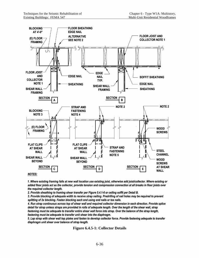
Techniques for the Seismic Rehabilitation of Chapter 6 - Type W1A: Multistory, Existing Buildings: FEMA 547 Multi-Unit Residential Woodframes
6-36
Figure 6.4.5-1: Collector Details

Techniques for the Seismic Rehabilitation of Chapter 6 - Type W1A: Multistory, Existing Buildings: FEMA 547 Multi-Unit Residential Woodframes
6-37
framing member without any splices being required. Where additional length of attachment to the diaphragm is required, splicing of the collector framing in accordance with Figure 6.4.5-2 is needed. Often framing in older buildings has a significant lap length over interior supports, sometimes making a direct nailed, screwed or bolted connection between existing members possible. Where bolts are used, detailed attention is needed to provide required bolt end and edge distances and spacing. Alternate splice approaches include steel straps and plates. Where collector member connection to the diaphragm above is not practical, a wood structural panel soffit, as shown in Detail B can be used to transfer load from the collector to the diaphragm. A minimum soffit width of four feet will generally ensure that at least one row of diaphragm edge nailing is engaged. For large unit shears, additional soffit width and length can distribute loads further. Figures 6.4.5-1C through 6.4.5-1E illustrate collector details where the existing framing is perpendicular to the wall. Because continuous framing is not available to act as a collector, steel straps or sections are used. Straps will generally be assumed to only carry tension loads. Blocking, already provided for shear transfer is assumed to carry compression loads. Blocking needs to have a tight fit in order to minimize deformation. Detailing is needed if splices will occur in the collector. Figure 6.4.5-3 illustrates an elevation of a collector where framing is perpendicular to the shear wall, corresponding to Figures 6.4.5-1C or 6.5.4-1D.
Design and Detailing Considerations Research basis: Testing of shear transfer connections between wood structural panel diaphragms and shear walls below was conducted by Ficcadenti et al. (2004). No research applicable to steel straps and blocking for collectors has been identified. Deformation in the collector: In order to be the most effective, the deformation of a collector should be as compatible as possible with the roof diaphragm it is attached to. Generally roof diaphragms in W1A buildings will be short span and quite stiff, suggesting that a stiff collector is preferable. This can be best achieved through use of existing framing members of as long lengths as possible, as illustrated in Figure 6.4.5-2. Splices in the collector members should also be reasonably stiff, as slip at the splice could result in tension in the diaphragm. Where framing runs perpendicular to the framing direction, there is sometimes little choice but to use steel straps for tension and blocking or framing members for compression, as shown in Figure 6.4.5-3. Unless the straps are reasonably stiff and blocking is installed tight, significant deformation could occur in the collector, resulting in limited efficiency for transferring loads. Although this type of collector is used commonly in new construction and rehabilitation, little is know about its effectiveness and resulting building performance. Conversely, however, significant distress in diaphragms in W1A buildings has only been seen at significant changes in geometry such as re-entrant corners (Schierle, 2002). If collectors are to be installed, it is recommended that they be made as stiff and tight-fitting as possible. Sizing of the collector member using overstrength forces or as force-controlled actions will help keep the collector stiff, therefore increasing likely performance.

Techniques for the Seismic Rehabilitation of Chapter 6 - Type W1A: Multistory, Existing Buildings: FEMA 547 Multi-Unit Residential Woodframes
6-38
Figure 6.4.5-2: Collector Using Existing Framing Parallel to the Shear Wall

Techniques for the Seismic Rehabilitation of Chapter 6 - Type W1A: Multistory, Existing Buildings: FEMA 547 Multi-Unit Residential Woodframes
6-39
Figure 6.4.5-3: Collector Using Added Blocking at Framing Perpendicular to Shear Wall
Where the top of the existing diaphragm sheathing cannot be accessed for additional sheathing nailing, sheathing added at the ceiling soffit can help distribute forces into the existing diaphragm, as shown in Figure 6.4.5-1B.
Cost and Disruption Considerations Removal of existing floor or roof finishes to nail diaphragm sheathing into new collector members can be both costly and disruptive. It is, however, going to provide the most predictable performance and is recommended for highly loaded walls and where a performance objective higher than life-safety is intended. Other fastening methods can be calculated and detailed, however not enough is known about their ability to perform adequately.
Construction Considerations Tight fit of framing, blocking and straps is critical to limiting deformation and improving performance of the collectors and shear transfer connections.
Proprietary Concerns There are no proprietary concerns with this rehabilitation technique other than the use of proprietary connectors as part of the assemblage.

Techniques for the Seismic Rehabilitation of Chapter 6 - Type W1A: Multistory, Existing Buildings: FEMA 547 Multi-Unit Residential Woodframes
6-40
6.5 References ACI, 2005, Building Code Requirements for Reinforced Concrete and Commentary, ACI 318, American Concrete Institute, Farmington Hills, MI. AF&PA, 2005, Special Design Provisions for Wind and Seismic, ASD/LRFD, American Forest & Paper Association, Washington, D.C. AISC, 2005, Seismic Provisions for Steel Buildings, American Institute of Steel Construction, Chicago, IL. APA, Revised 2000, Research Report 138, Plywood Diaphragms, APA The Engineered Wood Association, Tacoma, WA. APA, Revised 1999, Research Report 158, Preliminary Testing of Wood Structural Panel Shear Walls Under Cyclic (Reversed) Loading, APA The Engineered Wood Association, Tacoma, WA. ASCE, 2005, Minimum Design Loads for Buildings and Other Structures (ASCE 7), American Society of Civil Engineers, Reston VA. City of Los Angeles and SEAOSC, 1994, Wood Frame Construction Report and Recommendations, City of Los Angeles and Structural Engineers Association of Southern California, Los Angeles, CA. Cobeen, K., J. Russell, and J.D. Dolan, 2004, Recommendations for Earthquake Resistance in the Design and Construction of Woodframe Buildings, CUREE Publication No. W-30, Consortium of Universities for Research in Earthquake Engineering, Richmond, CA. FEMA, 2000, Prestandard and Commentary for the Seismic Rehabilitation of Buildings (FEMA 356), Federal Emergency Management Agency, Washington, D.C. FEMA, 1998, NEHRP Recommended Provisions for Seismic Regulations for New Buildings and Other Structures (FEMA 302), Federal Emergency Management Agency, Washington, D.C. Ficcadenti, S., E. Freund, G. Pardoen, and R. Kazanjy, 2004, Cyclic Response of Shear Transfer Connections Between Shear Walls and Diaphragms in Woodframe Construction, CUREE Publication No. W-28, Consortium of Universities for Research in Earthquake Engineering, Richmond, CA. Fischer, D., A. Filiatrault, B. Folz, C.M. Uang, and F. Seible, 2001, Shake Table Tests of a Two-Story Woodframe House, CUREE Publication No. W-06, Consortium of Universities for Research in Earthquake Engineering, Richmond, CA. Fonseca, F., S. Rose and S. Campbell, 2002, Nail, Screw and Staple Fastener Connections, CUREE Publication No. W-16, Consortium of Universities for Research in Earthquake Engineering, Richmond, CA.

Techniques for the Seismic Rehabilitation of Chapter 6 - Type W1A: Multistory, Existing Buildings: FEMA 547 Multi-Unit Residential Woodframes
6-41
ICBO, 1997, Uniform Building Code, International Conference of Building Officials, Whittier, CA. ICBO, 2001, Guidelines for Seismic Retrofit of Existing Buildings (GSREB), International Conference of Building Officials, Whittier, CA. ICC, 2003a, International Building Code, International Code Council, Country Club Hills, IL. ICC, 2003b, International Existing Building Code (IEBC), International Code Council, Country Club Hills, IL. ICC, 2005a, 2003 International Existing Building Code (IEBC) Commentary, International Code Conference, Country Club Hills, IL. ICC, 2005b, Proposed Changes to the 2003 IEBC, International Code Council, Country Club Hills, IL. ICC Peninsula Chapter, 2004, Simplified Design Procedure for Structural Steel Ordinary Moment-Resisting Frame (OMRF) 9/3/04 draft), ICC Peninsula Chapter, CA. Lizundia, B. and W. Holmes, 2000, Practical Solutions for Improving the Seismic Performance of Buildings with Tuckunder Parking, prepared for the City of San Jose Department of Housing and Office of Emergency Services, San Jose, CA. Mahaney, J. A. and B. E. Kehoe, 2002, Anchorage of Woodframe Buildings, Laboratory Testing Report, CUREE Publication No. W-14, Consortium of Universities for Research in Earthquake Engineering, Richmond, CA. Mahin, S., 1980s, personal communication. Mosalam, K., et al., 2002, Seismic Evaluation of an Asymmetric Three-Story Woodframe Building, CUREE Publication No. W-19, Consortium of Universities for Research in Earthquake Engineering, Richmond, CA. Nelson, R., 2005, personal communication. Nelson, R. and R. Hamburger, 1999, “Hold-down Eccentricity and the Capacity of the Vertical Wood Member,” Building Standards, November-December 1999, International Conference of Building Officials, Whittier, CA. Ni, C. and E. Karacabeyli, 2000, “Effect of Overturning Restraint on Performance of Shear Wall,” Proceedings of the World Conference on Timber Engineering, University of British Columbia, Vancouver, CA.

Techniques for the Seismic Rehabilitation of Chapter 6 - Type W1A: Multistory, Existing Buildings: FEMA 547 Multi-Unit Residential Woodframes
6-42
Pardoen, G., A. Waltman, R. Kazanjy, E. Freund, and C. Hamilton, 2003, Testing and Analysis of One-Story and Two-Story Walls Under Cyclic Loading, CUREE Publication No. W-25, Consortium of Universities for Research in Earthquake Engineering, Richmond, CA. Porter, K., J. Beck, H. Seligson, C. Scawthorn, L.T. Tobin, R. Young and T. Boyd, 2002, Improved Loss Estimation for Woodframe Buildings, CUREE Publication No. W-18, Consortium of Universities for Research in Earthquake Engineering, Richmond, CA. Pryor, S. 2002, The Effect of Eccentric Overturning Restraint in Complete Shear Wall Assemblies, Simpson Strong-Tie Company, Inc., Dublin, CA. Rutherford & Chekene, 2000, Seismic Rehabilitation of Three Model Buildings with Tuckunder Parking: Engineering Assumptions and Cost Information, prepared for the City of San Jose Department of Housing and Office of Emergency Services, May. Salenikovich, A., 2000, The Racking Performance of Light-Frame Shear Walls, Virginia Polytechnic Institute and State University, Blacksburg, CA. Salenikovich, A. and J. Dolan, 1999, “Effects of Aspect Ratio and Overturning Restraint on Performance of Light-Frame Shear Walls Under Monotonic and Cyclic Loading,” Proceedings of the Pacific Timber Engineering Conference, 1999, Volume 3, New Zealand Forest Research Institute, Rotorua, New Zealand. Schierle, G.G., 2002, Northridge Earthquake Field Investigations: Statistical Analysis of Woodframe Damage, CUREE Publication No. W-09, Consortium of Universities for Research in Earthquake Engineering, Richmond, CA. Schierle, G. G. editor, 2001, Woodframe Project Case Studies, CUREE Publication No. W-04, Consortium of Universities for Research in Earthquake Engineering, Richmond, CA. SEAOC (Structural Engineers Association of California), 2002, Recommended Guidelines for Ordinary Moment Frames (OMF) for Buildings, drafted by the SEAOSC Steel Ad-Hoc Committee for the SEAOC Seismology Committee (August 5, 2002 version), Structural Engineers Association of California, Sacramento, CA. Seismic Safety Commission, State of California, 1994, 1994 Northridge Earthquake Buildings Case Studies Project (Proposition 122; Product 3.2 SSC 94-06), Sacramento, CA. Steinbrugge, J., V. Bush, and J. Johnson, 1996, “Standard of Care in Structural Engineering Woodframe Multiple Housing,” Proceedings, 1996 Convention, Structural Engineers Association of California, Structural Engineers Association of California, Sacramento, CA. Vukazich, S., 1998, The Apartment Owner’s Guide to Earthquake Safety, City of San Jose, San Jose, CA.

Techniques for the Seismic Rehabilitation of Chapter 6 - Type W1A: Multistory, Existing Buildings: FEMA 547 Multi-Unit Residential Woodframes
6-43
Zacher, E. and R.G. Gray, 1985, “Dynamic Tests of Woodframed Shear Panels,” Proceedings, 1985 Convention, Structural Engineers Association of California, Structural Engineers Association of California, Sacramento, CA.

Techniques for the Seismic Rehabilitation of Existing Buildings: FEMA 547 Chapter 7 - Type W2: Woodframes, Commercial and Industrial
7-1
Chapter 7 - Building Type W2: Woodframes, Commercial and Industrial
7.1 Description of the Model Building Type Building Type W2 consists of commercial, institutional, and smaller industrial buildings constructed primarily of wood framing. Most W2 buildings have first floor slab-on-grade construction; however, woodframe floors supported on foundation walls or cripple walls occur. The upper floor and roof framing consist of wood joists and can include wood or steel trusses, beams, and columns. Post and beam framing is common at interior and at storefronts or garage openings. Lateral forces are resisted by woodframe diaphragms and shear walls. In older buildings, steel rod bracing systems may also be used in place of diaphragms. In newer buildings, wood shear walls are sometimes used in combination with isolated concrete or masonry shear walls or steel braced frames or moment frames. Figure 7.1-1 provides one illustration of this building type.
Figure 7.1-1: Building Type W2: Woodframes, Commercial and Industrial
Design Practice Design practice for W2 buildings can include no design, design per conventional constructions provisions, engineered gravity design and conventional construction bracing, and engineered gravity and lateral design. More W2 buildings are likely to have an engineered gravity design than W1 and W1A buildings because the framing systems often fall beyond conventional construction provisions. Lateral bracing of multistory W2 buildings in accordance with conventional construction provisions was permitted by the UBC (ICBO, 1994) through the 1994

Techniques for the Seismic Rehabilitation of Existing Buildings: FEMA 547 Chapter 7 - Type W2: Woodframes, Commercial and Industrial
7-2
edition. Construction of single-story W2 buildings using conventional construction provisions is still permitted under the IBC (ICC, 2003). In California, woodframe school buildings constructed in the 1950s included engineered lateral-force-resisting systems with tie-down anchors and diagonal lumber or plywood sheathed shear walls and diaphragms (Jephcott and Hudson, 1974). Commercial construction in California would generally be anticipated to match school construction, with a time lag. It is anticipated that most W2 buildings constructed today will have engineered gravity and lateral designs.
Walls and Other Vertical Elements While wall bracing materials can include the same range discussed for W1 buildings, the use of diagonal lumber sheathing or wood structural panel sheathing is much more likely in W2 buildings. The use of overturning anchorage would be varied between the 1950s and 1970s, but common in engineered buildings from the 1980s on. W2 buildings often have significantly fewer interior bracing walls than W1 and residential portions of W1A buildings. School buildings have moderate room sizes. Commercial buildings with simple geometries are often braced only at the building perimeter, creating large open rooms. Interior bracing may be added for more complex geometries. In newer commercial buildings, concrete or masonry shear walls, steel moment frames, or steel braced frames are sometimes used at the street front or as interior bracing walls in order to maximize the occupant’s or user’s ability to see across the retail or office space. These vertical elements are used specifically because needed bracing capacity can be provided by much shorter element lengths than with woodframe shear walls. Inclusion of these vertical elements requires additional attention to force distribution, potential torsional irregularities, and collectors adequate to transmit lateral loads to the elements. Cripple walls, also discussed with the W1 building type, sometimes occur in W2 buildings. See Chapter 5.
Floor and Roof Diaphragms Floor and roof diaphragms include the same materials as the W1 building type; however, plank and beam systems are rare in W2 buildings. Significant in W2 buildings is the occurrence of longer diaphragm spans and more complicated roof diaphragm configurations. The longer spans should result in larger force and deformation demands in the diaphragms and more out-of-plane movement of walls following the diaphragm deflection. More complicated roof configurations require attention to boundary members at diaphragm edges and vertical offsets in chords and collectors.
7.2 Seismic Response Characteristics Many W2 buildings, like Building Types W1 and W1A are short period with inelastic behavior concentrated in the vertical elements. Some W2 buildings (primarily single story), however, have long-span diaphragms, creating the possibility of high stresses, inelastic behavior, and high deformation in the diaphragm.

Techniques for the Seismic Rehabilitation of Existing Buildings: FEMA 547 Chapter 7 - Type W2: Woodframes, Commercial and Industrial
7-3
7.3 Common Seismic Deficiencies and Applicable Rehabilitation Techniques
Very little information has been published on the earthquake performance of W2 buildings. Earthquake reconnaissance report discussions of wood buildings have tended to focus on residential rather than commercial and light industrial uses. One exception to this is an exhaustive and detailed review school building performance in the 1971 San Fernando earthquake (Jephcott and Hudson, 1974). Only occasional and generally moderate damage is reported to have occurred in one-story and two-story woodframe school buildings. This is consistent with observations of schools made following the Northridge earthquake (EERI, 1996). For schools, however, nonstructural damage was reported to be significant. While reports of damage are scarce, the construction materials and demands are essentially the same as in W1 and W1A buildings, and many of the vulnerabilities and damage types should be expected to be similar. In fact, the generally larger building size and fewer interior walls should make W2 buildings more vulnerable than W1 or W1A. This was true in a case study of the Satellite Student Union Center at California State University, Northridge (Schierle, 2001), where significant damage to finish materials occurred. In addition, the W2 category includes buildings such as churches that often have very irregular building configurations, which should make them susceptible to damage. See below for general discussion and Table 7.3-1 for a detailed compilation of common seismic deficiencies and rehabilitation techniques for the Building Type W2.
Global Strength and Stiffness Global strength and stiffness can be of concern in W2 buildings. This is particularly true where use of the first story results in few structural and nonstructural walls and open fronts. Rehabilitation is commonly addressed by the addition or enhancement of wood shear walls, or the addition of steel moment frames, steel braced frames or concrete or masonry shear walls. Where W2 buildings are large in plan area, it may become practical to introduce a steel braced frame to resist lateral loads. The braced frame can resist higher loads than wood shear walls and lighter moment frames, allowing concentration of lateral loads into fewer and shorter bracing elements. This increases the level of force in the collector and at the base resisting shear and overturning. Occasionally concrete or masonry shear walls are used for rehabilitation; this must be done with caution however, because the weight of the wall will increase seismic forces perpendicular to the wall and attention to wall anchorage is required.
Configuration The open-front torsional irregularities and weak cripple wall configuration deficiencies introduced in W1 and W1A buildings are equally applicable to W2 buildings. In addition, mixing of lateral force systems in W2 buildings can lead to torsional irregularities. Where shear walls are mixed with other vertical bracing elements, care should be taken in evaluating the distribution of lateral forces and deformations. Torsional irregularity may have contributed to damage to the CSU Northridge Satellite Student Center (Schierle, 2001). Common measures for rehabilitation of torsional irregularities include the addition of steel moment frames, wood shear walls, steel braced frames and concrete or masonry shear walls.

Techniques for the Seismic Rehabilitation of Existing Buildings: FEMA 547 Chapter 7 - Type W2: Woodframes, Commercial and Industrial
7-4
Table 7.3-1: Seismic Deficiencies and Potential Rehabilitation Techniques for W2 Buildings Deficiency Rehabilitation Technique
Category Deficiency Add New Elements Enhance Existing Elements
Improve Connections Between Elements
Reduce Demand Remove Selected Components
Global Strength
Insufficient in-plane wall strength
Wood structural panel shear wall [6.4.2]
Steel braced frame [7.4.1]
Steel moment frame [6.4.1]
Enhance woodframe shear wall [6.4.2]
Uplift anchorage and compression posts [6.4.4]
Replace heavy roof finish with light finish
Global Stiffness
Insufficient in-plane wall stiffness
Wood structural panel shear wall [6.4.2]
Steel braced frame [7.4.1]
Steel moment frame [6.4.1]
Enhance woodframe shear wall [6.4.2]
Uplift anchorage and compression posts [6.4.4]
Weak story, missing or weak cripple wall
Wood structural panel shear wall [5.4.3], [6.4.2]
Add woodframe cripple wall
Add continuous foundation and foundation wall
Enhance woodframe shear wall [6.4.2]
Enhance woodframe cripple wall [5.4.4]
Configuration
Torsional irregularity including open front
Wood structural panel shear wall [6.4.2]
Proprietary wall Steel moment frame
[6.4.1] Concrete or masonry
wall
Enhance woodframe shear wall [6.4.2]
Inadequate shear anchorage to foundation
Anchorage to foundation [5.4.3]
Load Path
Inadequate overturning anchorage
Uplift anchors and compression posts [6.4.4]

Techniques for the Seismic Rehabilitation of Existing Buildings: FEMA 547 Chapter 7 - Type W2: Woodframes, Commercial and Industrial
7-5
Table 7.3-1: Seismic Deficiencies and Potential Rehabilitation Techniques for W2 Buildings Deficiency Rehabilitation Technique
Category Deficiency Add New Elements Enhance Existing Elements
Improve Connections Between Elements
Reduce Demand Remove Selected Components
Inadequate shear transfer in wood framing
Enhance load path for shear [5.4.1], [6.4.5]
Load Path (continued)
Inadequate collectors to vertical elements
Enhance existing collector [7.4.2]
Add collectors [6.4.5], [7.4.2]
Inadequate in-plane strength and/or stiffness
Enhanced existing diaphragm [22.2.1]
Replace heavy roof finish with light finish
Inadequate chord capacity
Enhance chord members and connections [22.2.2]
Excessive stresses at openings and irregularities
Enhance diaphragm detailing
Diaphragms
Re-entrant corners
Enhance diaphragm detailing
Foundations See Chapter 23 [ ] Numbers note in brackets refer to sections containing detailed descriptions of rehabilitation techniques.

Techniques for the Seismic Rehabilitation of Existing Buildings: FEMA 547 Chapter 7 - Type W2: Woodframes, Commercial and Industrial
7-6
W2 buildings with inadequate cripple wall bracing and foundation anchorage are just as vulnerable as similar W1 and W1A buildings. Rehabilitation of these deficiencies is recommended to be highest priority. For W2 buildings, use of an engineered rather than prescriptive design for cripple wall bracing and bolting is recommended.
Load Path The load path deficiencies in W2 buildings are much the same as W1 and W1A buildings. Rehabilitation measures typically involve fasteners and connectors to resist shear and overturning, and addition of collectors. As in W1 buildings, anchorage to the foundation is a high priority for rehabilitation in W2 buildings.
Diaphragm Deficiencies W2 buildings can have highly irregular diaphragms, with vertical offsets, folded plates, and saw-tooth configurations. Rehabilitation of chords and collectors is key to adequate performance of irregular diaphragms. Rehabilitation enhancing the capacity of the diaphragm is discussed in Chapter 22.
7.4 Detailed Description of Techniques Primarily Associated with This Building Type
7.4.1 Add Steel Braced Frame (Connected to Wood Diaphragm)
Deficiency Addressed by Rehabilitation Technique This rehabilitation technique addresses inadequate global or local strength or stiffness through the addition of a new steel braced frame element.
Description of the Rehabilitation Technique Figure 7.4.1-1A illustrates an elevation of a steel braced frame added in a W2 building. This type of element is generally introduced because it can provide needed bracing capacity in a short element length. The resulting highly loaded element will almost always require the addition of a significant collector to transfer load into the top and the addition of a significant new foundation to transmit forces to the supporting soils. Because existing foundations and collectors would not likely be adequate, it is common to add these elements in an area clear of existing foundations and beams. Figures 7.4.1-1B1 and 7.4.1-1B2 illustrate unit shear transfer over the length of the braced frame for framing perpendicular and parallel to the frame. Figures 7.4.1-1C1 and 7.4.1-1C2 illustrate collector members and their connection to framing perpendicular and parallel to the frame. These details are discussed further in Section 7.4.2. Figure 7.4.1-2 illustrates a two-story steel braced frame added in a W2 building. Significant in this detail is that the second floor is opened up allowing the braced frame to run continuous over the two-story height. Installing a separate frame at each story would lead to unmanageable connection details; the two-story configuration provides the strongest and stiffest solution. Shear

Techniques for the Seismic Rehabilitation of Existing Buildings: FEMA 547 Chapter 7 - Type W2: Woodframes, Commercial and Industrial
7-7
Figure 7.4.1-1A: Steel Braced Frame Added in W2 Building
Figure 7.4.1-1B: Shear Transfer and Collector for Steel Braced Frame

Techniques for the Seismic Rehabilitation of Existing Buildings: FEMA 547 Chapter 7 - Type W2: Woodframes, Commercial and Industrial
7-8
Figure 7.4.1-1C: Shear Transfer and Collector for Steel Braced Frame
Figure 7.4.1-2: Two-Story Steel Braced Frame in a W2 Building

Techniques for the Seismic Rehabilitation of Existing Buildings: FEMA 547 Chapter 7 - Type W2: Woodframes, Commercial and Industrial
7-9
transfer, collectors, and frame member bracing need to be provided at the second floor as well as the roof.
Design Considerations Research basis: See Chapter 9 of this document for detailed discussion of steel braced frames. No research applicable to steel braced frames in wood buildings has been identified. Foundation: The cost of the new braced frame foundation will be a significant part of the cost of this rehabilitation measure. Generally, the dead load available to resist foundation uplift will be minimal, so a large and heavy foundation is often needed. In some cases, it may be necessary to resort to drilled piers or helical anchors to provide uplift resistance.
Detailing Considerations See Chapter 9 for discussion of detailing of the steel braced frame. See Section 5.4.1 for discussion of basic issues related to rehabilitation of woodframe structure, including wood shrinkage and splitting. These issues are pertinent to load path connections for attachment of steel frames and collectors into the existing woodframe structure. Steel Connections: Details for connections within the steel braced frame and from the frame to the collector will need to give careful consideration to access for field assembly and field welding. Out-of-plane bracing will be required at the top of the columns and as required by the AISC Seismic Provisions for Structural Steel Buildings (AISC, 2005) along the length of the beam. See Section 6.4.1 for discussion of similar connection at a steel moment frame.
Cost and Disruption Considerations The addition of the steel frame will be disruptive to the area immediately surrounding the frame. Field welding is very difficult to avoid when adding steel braced frames to existing buildings, but should be minimized as much as possible. See Section 7.4.2 for discussion of interruption due to the steel collector.
Construction Considerations Placement of the steel columns is one of the significant construction challenges, particularly in a multistory frame as shown in Figure 7.4.1-2. It may be desirable to place the steel columns and then cast the foundation and/or slab concrete around them. This allows the depth of the footing to be used for maneuvering the steel column. See Section 6.41 for discussion of field welding issues.
Proprietary Concerns There are no proprietary concerns with this rehabilitation technique.
7.4.2 Provide Collector in a Wood Diaphragm
Deficiency Addressed by Rehabilitation Technique This rehabilitation technique addresses provision of collectors to new high capacity vertical elements in wood diaphragm buildings. This technique is primarily intended for use with steel braced frames, as discussed in Section 7.4.1, but would also be applicable to a collector for a
Techniques for the Seismic Rehabilitation of Existing Buildings: FEMA 547 Chapter 7 - Type W2: Woodframes, Commercial and Industrial
7-10
new concrete or masonry shear wall in a W2 building. Sections 6.4.5 and 5.4.1 discuss shear transfer and collectors for woodframe vertical elements with low to moderate loads.
Description of the Rehabilitation Technique Figures 7.4.1-1C1 and 7.4.1-1C2 illustrate a steel collector member added perpendicular or parallel to existing diaphragm framing. Fastening is provided for shear transfer between the collector and the diaphragm. As discussed in Section 7.4.1, it is assumed that this collector is added in a location away from existing continuous framing members. See Section 6.4.5 for collector alternatives where this is not the case. In Figure 7.4.1-1C1 new blocking is added, and nailing is provided between the diaphragm sheathing and blocking and between the blocking and a wood nailer. The nailer is attached to the collector with welded steel studs. A 3x framing member is shown as the collector because it gives better bolt values and because it provides enough depth to allow counter sinking of the washer if required. In Figure 7.4.1-1C2, a wood structural panel ceiling soffit is used to distribute collector forces into the existing diaphragm.
Design Considerations Research basis: No research applicable to installation of steel braced frames in a W2 building have been identified; however Section 6.4.1 discussion of shear transfer and collector detailing for steel moment frames (Mosalam et al., 2002) (Cobeen, Russell, and Dolan, 2004) is similar to this technique. Design demand: The primary deformation in a wood diaphragm should occur as nail slip in the fasteners attaching the sheathing to the framing. The most effective collector will allow this slip to occur, while not adding other sources of significant deformation. This is why the collector is illustrated as a substantial steel section rather than a light steel strap. The collector and connections would require design for overstrength forces in accordance with current building codes. Similarly, use of force-controlled actions would be appropriate when using rehabilitation guidelines. Design to avoid yielding of the steel section is recommended. Nailing of the existing sheathing to the framing or blocking should not be increased beyond what is required for design level forces or deformation-controlled actions. Note, however, that design level forces may require two rows of diaphragm edge nailing at the collector member, as the sum of the unit shear from two sides may be up to twice the diaphragm unit shear capacity. It is highly recommended that roof sheathing or floor finish materials be removed to allow the sheathing edge nailing to be installed from the top of the existing sheathing (Figure 5.4.1-6A). The other fastening and connections between the steel collector and existing roof sheathing should be designed for amplified forces to the extent possible in order to limit deformation. Connection alternatives shown in Figures 5.4.1-6B, 5.4.1-6C and 5.4.1-6D are not recommended for this level of demand.

Techniques for the Seismic Rehabilitation of Existing Buildings: FEMA 547 Chapter 7 - Type W2: Woodframes, Commercial and Industrial
7-11
Detailing Considerations Extent of collector: It is recommended that the collector be extended for the full dimension of the diaphragm wherever practical. If the collector is stopped short of the end, the change in diaphragm shear and therefore, deformation may occur at the collector end. Detailing of splices: Collector member splice locations should be planned, and splice details should be developed. Collector interruptions at beams may make logical splice locations. In Detail C2, it may be possible to move the collector up into the area between joists, thus avoiding collector breaks at beams. Where this is the case, ideal splice locations may be a few feet away from beams. Collector compression forces should be considered in splice design. Tolerances in existing floor framing: It can generally be expected that there will be some unevenness in the underside of the existing floor framing in the areas where the steel beam and collectors are to be added. It is best to anticipate and include in detailing shimming or other approaches to dealing with this tolerance. Detailing should show locations where shimming is acceptable, set upper limits on acceptable shimming, and adjust fastener capacity or length to account for reduced fastener penetration when shimming is provided.
Cost/Disruption The addition of collectors at the underside of roof or floor framing can be quite disruptive in buildings that are in use because of the extent of the work; however with adequate planning the work can generally be installed quickly. Where quick work is desirable, the ceiling should be removed for observation of existing conditions over the full extent of the collector prior to steel fabrication. In a one-story building, disruption of occupants can be reduced by installing the collector member on the roof top. This will require removal and replacement of roofing, and adjustment of roof drainage if drainage is altered by the added collector member.
Construction Considerations Welding of steel studs: Threaded steel studs should be welded to the steel collector in a fabrication shop with periodic special inspection. Field welding of the studs is discouraged due to a lower level of control and fire hazard. Smaller fabrication shops may not have fusion welding equipment for attachment of the studs. A fillet weld around the stud perimeter is acceptable when used with wood nailers. Slight routing of the wood nailer may be required to accommodate the weld.
Proprietary Concerns There are no proprietary concerns with this rehabilitation technique.
7.5 References AISC, 2005, Seismic Provisions for Steel Buildings, American Institute of Steel Construction, Chicago, IL. Cobeen, K., J. Russell, and J.D. Dolan, 2004, Recommendations for Earthquake Resistance in the Design and Construction of Woodframe Buildings, CUREE Publication No. W-30, Consortium of Universities for Research in Earthquake Engineering, Richmond, CA.

Techniques for the Seismic Rehabilitation of Existing Buildings: FEMA 547 Chapter 7 - Type W2: Woodframes, Commercial and Industrial
7-12
ICBO, 1994, Uniform Building Code, International Conference of Building Official, Whittier, CA. ICC, 2003, International Building Code, International Code Council, Country Club Hills, IL. Jephcott, D. K. and D. E. Hudson, September 1974, The Performance of Public School Plants During the San Fernando Earthquake, Earthquake Engineering Research Laboratory, California Institute of Technology, Pasadena, CA. Mosalam, K., et al., 2002, Seismic Evaluation of an Asymmetric Three-Story Woodframe Building, CUREE Publication No. W-19, Consortium of Universities for Research in Earthquake Engineering, Richmond, CA. Schierle, G. G. editor, 2001, Woodframe Project Case Studies, CUREE Publication No. W-04, Consortium of Universities for Research in Earthquake Engineering, Richmond, CA.


![Seismic Simulation of an Existing Steel Moment-Frame ...building were established based on the seismic rehabilitation guidelines of FEMA-351 and FEMA-356 [2]. The beam-column plastic](https://img.pdfslide.us/doc/110x75/60c5790555705a654c123c26/seismic-simulation-of-an-existing-steel-moment-frame-building-were-established.jpg)


![Techniques for Seismic Rehabilitation of Existing Bldgs 14710698-Fema547part3[1]](https://img.pdfslide.us/doc/110x75/55261d435503468e6e8b4b4f/techniques-for-seismic-rehabilitation-of-existing-bldgs-14710698-fema547part31.jpg)