Embed Size (px)
Citation preview
United States Patent [191 Counselman, III
4,912,475 Mar. 27, 1990
Patent Number:
Date of Patent:
[11]
[45]
[54] TECHNIQUES FOR DETERMINING ORBITAL DATA
[75] Inventor: Charles C. Counselman, III, Belmont, , Mass.
[73] Assignee: Massachusetts Institute of Technology, Cambridge, Mass.
[21] Appl. No.: 330,976 [22] Filed: Mar. 29, 1989
Related US. Application Data
[63] Continuation of Ser. No. 28,712, Mar. 20, 1987, aban cloned.
[51] Int. Cl.4 ................... H04B 7/185; G01S 5/02; G01C 21/00
[5.2] US. Cl. .................................. .. 342/352; 342/424; 364/459
[58] Field of Search ............. .. 342/352, 356, 357, 358, 342/424; 364/459
[56] References Cited U.S. PATENT DOCUMENTS
4,387,376 6/1983 Shcrrill et al. .................... .. 342/424 4,647,942 3/1987 Counselman, III .. 343/797 4,667,203 5/ 1987 Counselman, III .. 342/357 4,809,005 2/1989 Counselman, III ............... .. 342/352
FOREIGN PATENT DOCUMENTS
2120489 2/1986 United Kingdom .
OTHER PUBLICATIONS King et al., Surveying with GPS, Monograph, No. 9, School of Surveying, Univ. of New South Wales, 1985. Bossier et al., Using the Global Positioning System for ' Geodetic Positioning, pp. 553-563, Bull. Géod. 54 (1980). W. N. Christensen and J. A. Hogbom, Chap. 7, Entitled “Aperture Synthesis”, pp. 171-189, of Book Entitled “Radiotelescopes”, Published in 1969 by the Cambridge University Press, England. A. E. E. Rogers, “Very Long Baseline Interferometry with Large Effective Bandwidth for Phase Delay Mea surements”, Radio Science, vol. 5, No. 10, pp. 1239-1247, Oct., 1970.
1 A. E. E. Rogers, “Broad-Band Passive 90° RC Hybrid
we’
‘ate - /: \ mi", 10 I
with Low Component Sensitivity for Use in the Video Range of Frequencies”, Proceedings of the IEEE, vol. 59 (1971), pp. 1617-1618. C. C. Counselman, III and I. I. Shapiro, “Miniature Interferometer Terminals for Earth Surveying,” Pro ceedings of the Second International Symposium on Satel lite Doppler Positioning, vol. 11, pp. 1237-1286, Jan. 1979, Available from the University of Texas at Austin.
(List continued on next page.)
Primary Examiner-Thomas H. Tarcza Assistant Examiner-Gregory C. Issing Attorney, Agent, or Firm-Morgan & Finnegan
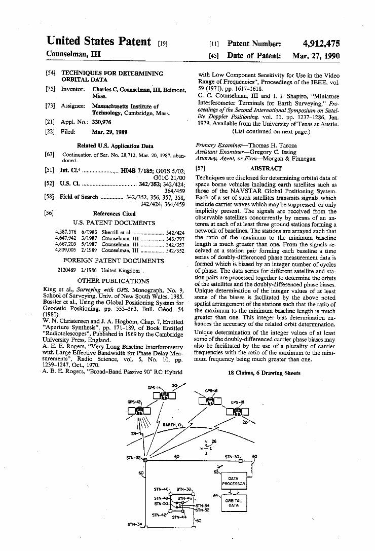
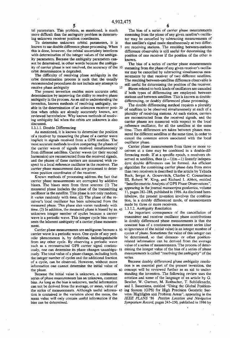
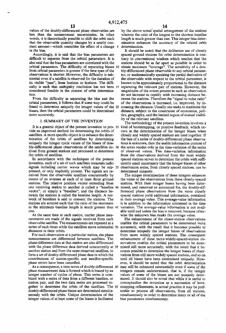
[57] ABSTRACT Techniques are disclosed for determining orbital data of space borne vehicles including earth satellites such as those of the NAVSTAR Global Positioning System. Each of a set of such satellites transmits signals which include carrier waves which may be suppressed, or only implicity present. The signals are received from the observable satellites concurrently by means of an an tenna at each of at least three ground stations forming a network of baselines. The stations are arrayed such that the ratio of the maximum to the minimum baseline length is much greater than one. From the signals re ceived at a station pair forming each baseline a time series of doubly-differenced phase measurement data is formed which is biased by an integer number of cycles of phase. The data series for different satellite and sta tion pairs are processed together to determine the orbits of the satellites and the doubly-differenced phase biases. Unique determination of the integer values of at least some of the biases is facilitated by the above noted spatial arrangement of the stations such that the ratio of . the maximum to the minimum baseline length is much greater than one. This integer bias determination en hances the accuracy of the related orbit determination.
Unique determination of the integer values of at least some of the doubly-differenced carrier phase biases may also be facilitated by the use of a plurality of carrier frequencies with the ratio of the maximum to the mini mum frequency being much greater than one.
18 Claims, 6 Drawing Sheets
\GPS- 6 695-15
SIN-30E 5°
DATA PROC ESSOR
ORBITAL DATA
4,912,475 Page 2
OTHER PUBLICATIONS
C. C. Counselman, III, I. I. Shapiro, R. L. Greenspan & D. B. Box, Jr., “Backpack VLBI Terminal with Sub centimeter Capability”, National Aeronautics & Space Admin. Conference Publication 2115, Entitled “Radio Interferometry Techniques for Geodesy”, pp. 409-414, Published in 1979. C. C. Counselman, III et al., “Very Long Baseline In terferometric Geodesy with GPS Satellites”, Proposed to NASA, Jul., 1980. Ron Hatch, “The Synergism of GPS Code and Carrier Measurements”, Proceedings of Third International Geo detic Symposium on Satellite Doppler Positioning, vol. 2, pp. 1213-1231, Presented in Feb. of 1982 by the Physi cal Science Laboratory of the New Mexico State Uni versity. G. Beutler, D. A. Davidson, R. B. Langley, R. Santerre, P. Vanicek and D. E. Wells, “Some Theoretical and Practical ‘Aspects of Geodetic Positioning Using Car rier Phase Difference Observations of GPS Satellites”, Published in Jul. 1984 as Technical Report No. 109 of Department of Surveying Engineering, of the Univer sity of New Brunswick, Canada. R. I. Abbot, Y. Bock, C. C. Counselman, III, R. W. King, S. A. Gourevitch and B. J. Rosen, Entitled “In terferometric Determination of GPS Satellite Orbits”, Proceedings of the First International Symposium on Pre cise Positioning with the Global Positioning System, vol. 1, .pp. 63-72, Published May 1985 by the National Geo detic Information Center, National Oceanic and Atmo spheric Administration, Rockville, Md., 20852, U.S.A. G. Beutler, W. Gurthner, I. Bauersima and R. Langley, Entitled “Modeling and Estimating the Orbits of GPS Satellites”, Proceedings of the First International Sympo sium on Precise Positioning with the Global Positioning System, vol 1, pp. 99-112, Published May 1985 by the National Geodetic Information Center, National Oce
anic and Atmospheric Administration, Rockville, Md, 20852, U.S.A. Bock et al., “Establishment of Three-Dimensional Geo detic Control by Interferometry with the Global Posi tioning System”, JGR, vol. 90, No. B9, pp. 7689-7703, Aug. 10, 1985. R. W. King, E. G. Masters, C. Rizos, A. Stolz and J. Collins, Monograph, No. 9, Entitled “Surveying with GPS”, Published by the School of Surveying, The Uni versity of New South Wales, Kensington, N.S.W. 2033, Australia, Nov. 1985. E. Beutler, W. Gurtner, M. Rothacher, T. Schildknecht and I. Bauersima, “Evaluation of the l984-Alaska-GP S-Campaign With the Bernese Second Generation Software”. G. Beutler, W. Gurtner, M. Rothacher, T. Schildknecht and I. Bauersima, “Using the Global Positioning System (GPS) for High Precision Geodetic Surveys: Highlights and Problem Areas”, IEEE Plans“ 86 Position Loca tion and Navigation Symposium Record”, pp. 243-250, Published 1986 by Institute of Electrical & Electronics Engineers, New York. G. Beutler, W. Gurtner, M. Rothacher, T. Schildknecht and I. Bauersirna, Entitled “Determination of GPS Or bits Using Double Difference Carrier Phase Observa tions from Regional Networks”, in the Proceedings of the fourth International Geodetic Symposium on Satellite Positioning, vol. 1, pp. 319-335, Published in 1986 by the Applied Research Laboratories of the University of Texas at Austin. Y. Bock, S. A. Gourevitch, C. C. Counselman, III, R. W. King and R. I. Abbot, “Interferometric Anslysis of GPS Phase Observations”, manuscripta geodaetica, vol. 11, pp. 282-288; Manuscript Rec’d by the Journal Apr. 2, 1986; Published Dec., 1986. Burkhard Schaffrin and Yehuda Bock, “A Uni?ed Scheme for Processing GPS Dual-Band Phase Obser vations,” l5-page Manuscript Submitted to Bulletin Geodesique, Dec. 3, 1986.
US. Patent Mar. 27, 1990 Sheet 1 of6 4,912,475
\ DATA PROCESSOR
ORBITAL DATA
STN-34
US. Patent Mar. 27, ~1990
I
I I I I I I I I I I l I | I I I I
I I I
I I
I I I I I l I I I I I I
I I l I I
sheet 2 on 4,912,475
\ePs-Iz
STATION STN-n 24 / —-—
_ _ _ _ _ _ _ _ _ _ _ _ _ _ _ _ ~ __ ____*_____~_____]
i ANTENNA I00
I
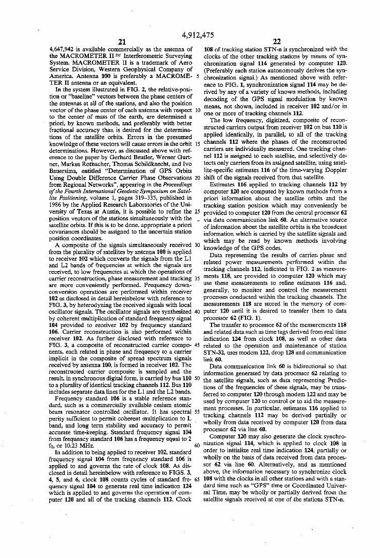
I IIO] I I
RECEIVER LOW-FREQ. TRACKING CHANNEL II2 I02 SIGNALS (ONE PER SATELLITE)
_——__I'
II I
/IO4 ESTI- MEAS'T ‘MATES H8 H6
FREQUENCY STANDARD CLOCK COMPUTER I20
I06 '08 _ .
II4/ I DATA I26“
MODEM
I I22
_______________________ __|2__8:'____________J
60\
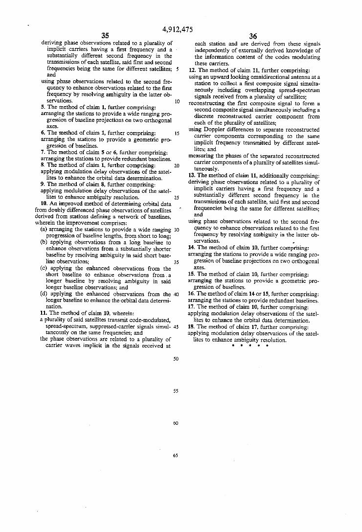
US. Patent Mar. 27, 1990 Sheet 4 of 6 4,912,475
/TRACKING CHANNEL I_I___ ' r ----------------------- "'1
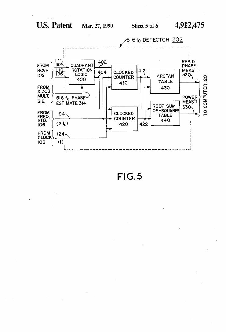
L1I I I ,94’\ i 616 f0 RESIDUAL PHASE Egg, i slsfo MEASUREMENT 32o,’
\ I DETECTOR POWER MEAs'T 33oW I X308 302 I V
E.
8 I / I _ : 3I2/ 3'4 I n: | I_12I=o . 32% , I" I I E | DETECTOR ' 332x _ 8 I 304 I V O n: : alo/ I § 2 L2I., I I 0: o 226\ I ' £5 E 1238, 480fo j 324\_ a
\ I DETECTOR | 334\ 2
Ito/7 I X 240 306 I V 8 '- |
8: / I E "11 3I6/ 3'8 I
FROM I24 :5: L2 2% = 326\— |
CLOCK q DETECTOR I 3361 ~ '08 (t) 8: 308 2|f PHASE 7
" 0 FROM N
TD. o..I | I06 (2%) 8: I H8}
' RANGE I
('21 GENERATOR I I 3Io/ i(FEEDBACK) I I I ' I l r I I I I I I I I I I I I I I I l I I I I I I I I__
RANGE RATE ESTIMATE 298 /
H6 FROM COMPUTER I20
4,912,475
TECHNIQUES FOR DETERMINING ORBITAL DATA
The US. government has rights in this invention 5 pursuant to Contract Number Fl9628-86-K-0O09 awarded by the Department of the Air Force.
This is a continuation of co-pending application Ser. No. 028,712, ?led Mar. 20, 1987, abandoned July 25, 1989. 10
TABLE OF CONTENTS
1. Background of the Invention 1.1. Field of the Invention 1.2. The Global Positioning System
1.2.1. GPS Satellite Orbits 1.2.2. Transmitted Signals
1.2.2.1. Carriers and Modulation 1.2.2.2. Carrier Reconstruction
1.3. Deriving Position Information from GPS Signals 1.3.1. Using Carrier Phase
1.3.1.2. Ambiguity Resolution 1.3.1.3. Effect of Orbital Uncertainty 1.3.1.4. Avoiding Ambiguity Resolution 1.3.1.5. Orbit Determination
15
25 i 2. Summary of the Invention
3. Brief Description of the Drawings 4. Detailed Description of Preferred Embodiment FIG. 1. System of Stations Linked to Data Processor FIG. 2. Tracking Station FIG. 3. Receiver FIG. 4. Tracking Channel FIG. 5. 616 f0 Detector FIG. 6. Range Generator
1. BACKGROUND OF THE INVENTION
1.1. Field of the Invention This invention relates to improved techniques for
determining orbital data of space traveling objects such as earth satellites, and more particularly to improved radio interferometric methods and instrumentation for determining such data.
Orbital data are data representative of the path of a satellite in space and, more speci?cally, of the position of a satellite at a particular time or as a function of time. Orbital data may represent’ an orbit in various ways. For example, a satellite’s position and velocity vectors may be speci?ed in rectangular coordinates at a certain ep och. Alternatively, the elements of an osculating or a mean ellipse may be given.
Radio interferometric data such as differences of carrier phase observations of satellite signals from a pair of receiving stations constitute a kind of orbital data. However, the present invention concerns the combina tion of carrier phase data from three or more receivers and the processing of the combined data to determine data more directly representative of the path or position of a satellite in space. Therefore, the term “orbital data” will be used herein to refer to the latter data, and the term “orbit determination” will be used to refer to the process of deriving such orbital data from the phase measurement data. Although the invention is disclosed with reference to
the satellites of the NAVSTAR Global Positioning System, or “GPS”, it applies as well to the determina tion of orbital data of other space traveling, radio trans mitting objects, such as the Soviet GLONASS satellites and certain other space craft.
30
35
45
50
60
65
2 1.2. The Global Positioning System The GPS is now in the process of being deployed by
the US. Department of Defense, and will be used mainly for purposes of navigation and position determi nation. About seven satellites of the GPS now orbit the earth and transmit radio signals by which users can determine their positions on earth. 1.2.1. GPS Satellite Orbits When complete, the Global Positioning System is
expected to include about 21 satellites orbiting the earth in three planes. About seven satellites will be distributed around a geocentric circular orbit in each of these planes; each plane will be inclined to the earth’s equator by an angle of about 55 degrees; and the equator cross ing points, or nodes, of the orbits will be about equally spaced in longitude, about 120 degrees apart. The altitudes of the orbits above the surface of the
earth are all about 20,000 km, and the common orbital period is about 24 hours as viewed from the rotating earth. Thus, the GPS satellites are not “geostationary”, but each appears to a ground-based observer to rise, move through the sky, and set daily. From any given point on the earth’s surface, at least four satellites will be in view at any time, 24 hours per day. Because the orbits are so high, a given satellite at a given time may be seen from‘widely separated points on the earth’s surface. 1.2.2. Transmitted Signals Each GPS satellite transmits microwave L-band
radio signals continuously in two frequency bands, cen tered at 1575.42 MHz and 1227.60 MHz and known as the “L1” and the “L2” bands, respectively. Within each of these GPS bands, the transmitted signal is a broad band, noise-like, pseudorandom signal which contains no discrete spectral components. The signals are there fore said to be carrier-suppressed. 1.2.2.1. Carriers and Modulation The term “carrier” is used herein in the same sense as
is usual in the radio art; that is, a carrier is a periodic wave of essentially constant amplitude, frequency, and phase. Information may be conveyed, or “carried” by varying the amplitude, frequency and/or phase of such a signal. A carrier may be called a “subcarrier” if its frequency is less than the bandwidth of the signal. A signal may include several carriers. For example, a broadcast television signal is said to include a video carrier and an audio carrier. Although no carriers are present in the GPS signals
as transmitted, various carriers may be said to be im plicit therein, in that such carriers may be recovered or reconstructed from the GPS signals.
Within each GPS satellite, a stable frequency stan dard such as an atomic cesium beam device provides a fundamental frequency of 5.115 MegaHertz, called f0, from which all other critical satellite frequencies are derived by integer multiplication or division. The fre quency of the Llband center frequency carrier of GPS signals is 308 times f0 or 1575.42 MegaHertz, and the frequency of the L2 band center frequency carrier is 240 times f0 or 1227.60 MegaHertz. The f0 fundamental frequency is a carrier frequency which may be recon structed from the GPS signals. GPS signals are bi-phase or quadriphase modulated.
In particular, quadrature components of an L band center frequency carrier are multiplied, in the satellite, with pseudorandom, binary valued waves m(t) and n(t). The m(t) and n(t) waveforms are aperiodic, but periodic carrier waves are implicit in them. Polarity or phase
4,912,475 3
reversals of m(t) and n(t) occur only at times which are integer multiples of ?xed time intervals tm and tn known as the chip widths of m(t) and n(t), respectively.
If m(t) reversed Polarity at every multiple of tm, then m(t) would be a periodic square wave with a frequency equal to l/(2tm). Because the polarity reversals actually occur pseudorandomly, just half the time on average, the l/(2tm) frequency carrier wave is suppressed, as is the band center frequency carrier.
Similarly, if n(t) reversed polarity at every multiple of tn, then n(t) would be a periodic square wave with a frequency equal to 1/(2tn). Again, because n(t) reverses polarity pseudorandomly, both the 1/(2tn)-frequency carrier and the band center frequency carrier are sup pressed.
In each GPS satellite’s transmitter, one quadrature component of the 308 f0 or 1575.42 MHz, L1 band cen ter frequency carrier is modulated with m(t), which has chip width tm equal to 5/f0 or about 977.5 nanoseconds. The orthogonal component of the L1 band center‘ fre quency carrier is modulated with n(t), which has chip width tn equal to 1/(2f0) or about 97.75 nanoseconds. The 240 f@ or 1227.60 MHz, L2 band center frequeneY carrier is modulated with only n(t). Thus, in the spread spectrum signal transmitted in the L1 band, at least three different carrier waves are implicitly present, with frequencies of f(;/ 10 (equal to 0.5115 MHz), f0 (equal to 5.115 MHz), and 308 f0 (equal to 1575.42 MHz). In the spread spectrum signal transmitted in the L2 band, at least two different carrier waves are implicitly present, with frequencies of f0 (5.115 MHZ) and 240 f0 (1227.60 MHz). Other carrier frequencies may also be implicit in the
GPS signals. For example, the m(t) wave is itself the product of several waves whose time intervals between polarity reversals are fixed integer multiples of tm. Thus, additional carriers whose frequencies are corre sponding submultiples of l/ (2 tm) are implicitly present. One of the waveforms or factors multiplied together to produce m(t), known as the “C/A” code waveform or C/A code sequence, is a satellite-specific, pseudoran dom, binary sequence of 1023 chips repeated periodi cally with a period of l millisecond, or a frequency of 1 kiloHertz. Another factor in m(t) is a stream of binary “naviga
tion” data having a 20-milliseconcl chip width, thus a 25 Hertz carrier frequency. These data include the current time indicated by the satellite’s clock, a description of the satellite’s current position in orbit, and a description of corrections to be applied to the time indicated by the satellite’s clock. These data are broadcast by the satel lites for use in the process of determining the position of a receiver from measurements of the received signals. Similar or identical data may be included in the n(t) wave which may modulate both the L1 and the L2 band center frequency carriers. 1.2.2.2. Carrier Reconstruction Various techniques are known for reconstructing
carrier waves from the spread spectrum signal received from a GPS satellite. In the conventional technique, the received signal is multiplied by a replica, generated locally, of the satellite-speci?c C/A code waveform present in m(t), or of the “P” or “Y” code which is present in n(t). In other techniques, no code sequence is generated in the receiver. Such codeless techniques may be utilized when the relevant code is unknown or to avoid code dependence.
15
45
50
55
65
4 An aspect of some carrier reconstruction techniques,
including the codeless technique used in the preferred embodiment of the present invention described herein below, is that the second harmonic rather than the fun damental frequency of an implicit carrier is recon structed. In the preferred embodiment, second-har monic frequencies of 616 f0 and 2 f0 are reconstructed from the GPS signals received in the L1 band, and frequencies of 480 f0 and 2 f0 are reconstructed from the signals received in the L2 band. 1.3. Deriving Position Information from GPS Signals Various methods are known for deriving position
information from a signal received from a GPS satellite. In some methods, the time delay of the pseudorandom code modulation of the signal is measured. In others, the phase of a periodic carrier wave implicit in the signal is measured. Time delay and carrier phase measurements may be combined. In any case, information relating both to the position of the receiver and to the position of the orbiting satellite is obtained. The present invention is primarily concerned with the determination of orbital position information. 1.3.1. Using Carrier Phase The position information obtainable by measuring the
phase of a GPS carrier wave, especially one of the relatively short wavelength, L1 or L2 band center fre quency carriers, is potentially much more accurate than the information obtainable by measuring the modula~ tion delay. However, the potential accuracy of carrier phase information can be difficult to achieve because carrier phase measurements are ambiguous. Their full potential cannot be realized unless the ambiguity prob lem can be resolved. Because resolving phase ambiguity is an important
aspect of the present invention, this problem and known methods of attacking or avoiding it are reviewed here inbelow. The ambiguity problem is a fundamental one affecting all types of phase measurements, but its nature and the difficulty of solving it depend strongly on the techniques used to collect and process the measure ments. The nature of the ambiguity problem, whether it can be solved, and if so how, depend particularly on how well the positions of the satellite and the receiving station are known. Uncertainty in knowledge of a satel lite orbital position causes more serious difficulty in solving the ambiguity problem than uncertainty in a fixed receiver position. Which position is unknown is critical because, for
example, a ?xed receiver position may be speci?ed for the entire time span of an extensive set of observations, by the values of just three coordinates (for example, latitude, longitude, and height). On the other hand, a minimum of six parameters must be speci?ed to define the orbit of a satellite, even for a relatively short time span. Techniques are known for solving the carrier phase
ambiguity problem in determining unknown receiver coordinates, but only when the relevant satellite orbital parameters are relatively well known. The most effi cient techniques known for receiver position determina tion rely on a method of phase data processing known as “double differencing”. In double difference phase processing, as described below, the problem of resolv
' ing carrier phase ambiguity appears as a problem of determining integer numbers called ambiguity parame ters.
The present invention addresses the problem of phase ambiguity in the context of determining unknown orbi
4,912,475 5
tal parameters. This problem, as mentioned, is much more difficult than the ambiguity problem in determin ing unknown receiver position coordinates. To determine unknown orbital parameters, it is
known to use double difference phase processing. When this is done, however, the orbital uncertainty interferes with determination of the integer values of the ambigu ity parameters. Because the ambiguity parameters can not be determined, in other words because the ambigu ity of carrier phase is not resolved, the accuracy of the orbit determination is degraded. The difficulty of resolving phase ambiguity in the
orbit determination process is such that the usually recommended procedures do not include any attempt to resolve phase ambiguity The present invention enables more accurate orbit
determination by improving the ability to resolve phase ambiguity in the process. As an aid to understanding the invention, known methods of resolving ambiguity, us able in the determination of an unknown receiver posi tion when orbits are already accurately known, are reviewed hereinbelow. Why known methods of resolv ing ambiguity fail when the orbits are unknown is also discussed. 1.3.1.1. Double Differencing As mentioned, it is known to determine the position
of a receiver by measuring the phase of a carrier wave implicit in signals received from a GPS satellite. The most accurate methods involve comparing the phases of the carrier waves of signals received simultaneously from different satellites. Carrier waves (or their second harmonics) are reconstructed from the received signals, and the phases of these carriers are measured with re spect to a local reference oscillator in the receiver. The carrier phase measurement data are processed to deter mine position coordinates of the receiver. Known methods of processing address the fact that
carrier phase measurements are corrupted by additive biases. The biases stem from three sources: (1) The measured phase includes the phase of the transmitting oscillator in the satellite. This phase is not only random; it varies randomly with time. (2) The phase of the re ceiver’s local oscillator has been subtracted from the measured phase. This phase also varies randomly with time. (3) In addition, the measured phase is biased by an unknown integer number of cycles because a carrier wave is a periodic wave. This integer cycle bias repre sents the inherent ambiguity of a carrier phase measure ment.
Carrier phase measurements are ambiguous because a carrier wave is a periodic wave. One cycle of any peri odic phenomenon is, by de?nition, indistinguishable from any other cycle. By observing a periodic wave such as a reconstructed GPS carrier signal continu ously, one can determine its phase changes unambigu ously. The total value of a phase change, including both the integer number of cycles and the additional fraction of a cycle, can be observed. However, without more information one cannot determine the initial value of the phase.
Because the initial value is unknown, a continuous series of phase measurements has an unknown, constant bias. As long as the bias is unknown, useful information can not be derived from the average, or mean, value of the series of measurements. Although useful informa tion is contained in the variation about the mean, the mean value will only contain useful information if the bias can be determined.
15
20
25
30
40
45
65
6 The bias of a series of carrier phase measurements
stemming from the phase of any given satellite’s oscilla tor may be cancelled by subtracting measurements of that satellite’s signal made simultaneously at two differ ent receiving stations. The resulting between-stations difference observable is still useful for determining the position of one receiver if the position of the other is known. The bias of a series of carrier phase measurements
stemming from the phase of any given receiver’s oscilla tor may be cancelled by subtracting simultaneous mea surements by that receiver of two different satellites. The resulting between-satellites difference observable is still useful for determining the position of the receiver.
Biases related to both kinds of oscillators are canceled if both types of differencing are employed: between stations and between satellites. This is known as double differencing, or doubly differenced phase processing. The double differencing method requires a plurality
of satellites to be observed simultaneously at each of a plurality of receiving stations. At each station, carriers are reconstructed from the received signals, and the carrier phases are measured with respect to the local reference oscillator, for all the satellites at the same time. Then differences are taken between phases mea sured for different satellites at the same time, in order to cancel the common errors associated with the local oscillator phase. _
Carrier phase measurements from three or more re ceivers at a time may be combined in a double-dif ferencing mode. If at a speci?c epoch, n receivers ob served m satellites, then (n— l)(m- l) linearly indepen dent double differences can be formed. An efficient algorithm for combining carrier phase data from more than two receivers is described in the article by Yehuda Bock, Sergei A. Gourevitch, Charles C. Counselman III, Robert W. King, and Richard I. Abbot, entitled “Interferometric Analysis of GPS Phase Observations”, appearing in the journal manuscripta geodaetica, volume 11, pages 282-288, published in 1986. As disclosed here inbelow, the present invention involves the combina tion, in a doubly differenced mode, of measurements made by three or more receivers. 1.3. 1.2. Ambiguity Resolution An important consequence of the cancellation of
transmitter and receiver oscillator phase contributions in doubly differenced phase measurements is that the constant bias of a continuous measurement series (due to ignorance of the initial value) is an integer number of cycles of phase. Sometimes the value of this integer can be determined, so that distance- or other position related information can be derived from the average value of a series of measurements. The process of deter mining the integer value of the bias of a series of phase measurements is called “resolving‘ the ambiguity” of the series. Because doubly differenced phase ambiguity resolu
tion is an essential part of the present invention, the concept will be reviewed further as an aid to under standing the invention. The following review uses the notation and some of the language of an article by G. Beutler, W. Gurtner, M. Rothacher, T. Schildknecht, and I. Bauersima, entitled “Using the Global Position ing System (GPS) for High Precision Geodetic Sur veys: Highlights and Problem Areas”, appearing in the IEEE PLANS ’86 Position Location and Navigation Symposium Record, pages 243-250, published in 1986 by
4,912,475 7
the Institute of Electrical and Electronics Engineers, New York. For clarity, many details are omitted here.
Let L represent the wavelength of a reconstructed carrier wave, that is, the speed of light 0 divided by the reconstructed carrier frequency. In the case of a re— ceiver which reconstructs the second harmonic of an implicit carrier frequency, the wavelength is computed from twice the implicit carrier frequency.
Let rik represent the distance or “range” between receiver k at the reception and measurement time, t, and satellite i at the time of transmission, (t—r"k/c). Let fk represent the phase of the klh receiver’s local
reference oscillator, and let fl represent the phase of the im satellite’s transmitting oscillator. Then the so-called “one way” phase observable fl'k,
for the signal received from the it,‘ satellite at the klh receiver, is given theoretically by the equation
ek=ri_ti-rk-(i/L)rik+Nit-. trn (Eq. 1) where all phases are expressed in cycles and N‘), is an integer expressing the intrinsic ambiguity of this phase observable. Four one~way phases measured at the same epoch t,
at a pair of receiving stations k and q and for pair of satellites i and j, are differenced to form a doubly differ enced observable: ‘
DDtiyq=(Fk~tiq)-(9k-tiq). (Eq. 2) Again, subscripts denote receivers and superscripts denote satellites. The double differencing cancels the transmitter and the receiver oscillator phases. The ef fects of the differences between the satellite-to-receiver distances, and a bias which is an integer number of cycles, remain:
oo?;!,,= -(i/L)oDri;Jq+Nik/',. (Eq. 3) Here, DDl‘ikjq is the doubly differenced range, and Niki}; is the integer bias, sometimes called the “ambiguity parameter”.
Determining uniquely the true integer value of the unknown bias of a continuous series of doubly-dif ferenced phase observations is called “resolving the ambiguity” of the series. If the ambiguity parameter of a series can be determined, it may be subtracted from each observation in the series, or otherwise accounted for. Then useful information may be derived from the average value of the series of measurements. Thus, the value of an observation series is enhanced by determina tion of the bias.
In general, a series of observed values of doubly-dif ferenced phase is composed of a mean, or average, value, plus a variation about the mean. Both the mean value and the variation about the mean contain poten tially useful information about the positions of the satel lites and the receivers. The mean value of the phase is related to the mean of the doubly—differenced satellite receiver distance, and the variation of the phase is re lated to the variation of this distance.
If the mean value includes an additive bias which is unknown, then one does not know the value of the position-related part, so it is difficult to derive meaning ful position information from the mean value. However, once the additive bias is known, the position-related part of the mean value of the observed phase is known and can contribute to determining the positions of the receivers.
If the positions of the satellites were unknown and the additive bias could be determined, the mean value of the observed phase could contribute to determining the
5
25
35
45
60
65
8 positions of the satellites. Determining the additive bias and applying the mean value information to determine the positions of satellites is an aspect of the present invention. One method of determining the integer bias of a series
of doubly-differenced phase observations is simply to utilize sufficiently accurate information from an exter nal source to calculate the value of the phase observable with an uncertainty of less than one-half cycle. A simple example of using information from an external source would be the use of independently derived information about the positions of the satellites and the stations to calculate the doubly differenced range, DDri/Jq, in Eq. 3. Substituting the actually observed value of the dou bly differenced phase for the theoretical value, DDfi/Jq, in Eq. 3 yields an equation which may be solved for the ambiguity parameter, Ni/Jq. Another example of using independently derived
information to determine the ambiguity parameter is the use of a “parallel” series of doubly-differenced observa tions, from the same pair of stations and for the same pair of satellites, and at one or more of the same mea surement epochs, of the satellite-to-station path length as inferred from the time delay of the code modulation of a satellite signal. This method was proposed in a paper published in 1979 by C. C. Counselman III, I. I. Shapiro, R. L. Greenspan, and D. B. Cox, Jr., entitled “Backpack VLBI Terminal with Subcentimeter Capa bility”, appearing in National Aeronautics and Space Administration Conference Publication 2115, “Radio Interferometry Techniques for Geodesy”, on pages 409-414. A detailed development of this method was given in a paper by Ron Hatch, entitled “The Syner gism of GPS Code and Carrier Measurements”, appear ing in the Proceedings of the Third International Geodetic Symposium on Satellite Doppler Positioning, volume 2, pages 1213-1231, published in 1982 by the Physical Science Laboratory of the New Mexico State Univer sity. This method relies on the ability to determine the
doubly-differenced range from observations of the modulation delay with sufficiently small uncertainty that the bias of the doubly-differenced center frequency carrier phase for the same station pair and satellite pair is computable with less than one-half éycle of error. An important aspect of this method is that it does not re quire determination or external knowledge of the geom etry. The satellite-to-receiver distance, whatever its value, delays the signal modulation and the center-fre quency carrier by the same amount. Therefore the abil ity to resolve ambiguities by this method is essentially independent of uncertainty in available knowledge of the station positions and the satellite orbits.
Unfortunately, it has proven extremely difficult in practice to measure the modulation delay of the signal with sufficient accuracy to ensure correct resolution of the L band center-frequency carrier phase ambiguities, and the utility of this method has so far been rather limited.
Related methods of resolving ambiguities in phase observations of GPS satellites are known in which pha ses are observed for a plurality of reconstructed carriers including one or more subcarriers. The phase of a sub carrier is indicative of modulation delay. Methods of resolving ambiguities in which carrier
phase observations are made at up to about ten different frequencies, including some closely spaced frequencies,
4,912,475 some widely spaced frequencies, and some progres sively spaced intermediate frequencies, are also known, as proposed for example by C. C. Counselman III and I. I. Shapiro in the paper entitled “Miniature Interferome ter Terminals for Earth Surveying” published in the Proceedings of the Second International Symposium on Satellite Doppler Positioninq, Vol. II, pp. 1237-1286, January 1979, available from the University of Texas at Austin. This method is akin to the method of bandwidth synthesis employed for the unambiguous measurement of delay in very long baseline .radio interferometry, as described in a publication by A. E. E. Rogers, entitled “Very Long Baseline Interferometry with Large Effec tive Bandwidth for Phase Delay Measurements”, ap pearing in Radio Science, vol. 5, no. 10, pages 1239-1247, October 1970. Simultaneous observation of different frequencies,
and/or the combination of code delay and carrier phase measurements, is also known to be useful for the pur pose of determining, and thereby eliminating, the fre quency-dependent effects of ionospheric refraction on the satellite signals. The known multiple-frequency and bandwidth syn
thesis methods are very much like the above mentioned GPS code-delay method; all are independent of, and do not involve knowledge or determination of, the satel lite-station geometry. Unfortunately, the signals trans mitted by the GPS satellites are not really suitable for use of the multiple-frequency and bandwidth synthesis methods. A serious problem is that the widths of the GPS L1 and L2 bands are too small in comparison with the frequency spacing between the bands. It is the rela tively narrow GPS signal bandwidth which also se verely limits the utility of the code~delay method. The reasons behind the limitation are related. As discussed herein below, the determination of satel
lite orbital data in accordance with the present inven tion involves the use of at least three receiving stations preferably including some closely spaced stations, some widely spaced stations, and stations with a progression of intermediate spacings. The spacings in this case refer to geometrical distance. However, an analogy exists between the use of progressively spaced’ stations and the use of progressively spaced frequencies. Although it may not be feasible to equip the GPS (or any other) satellites to transmit a suitable progression of frequen cies, it is indeed feasible to set up an array of tracking stations with a suitable progression of geometrical spac ings. In a sense, therefore, the present invention may be said to compensate for the gaps in the GPS frequency spectrum which limit the use of known multi-frequency and related techniques.
Similarly, where a system provides a suitable spacing of frequency components, the dependence on varied base line lengths is reduced. Of all known methods of resolving ambiguity in dou
bly-differenced phase observations, probably the most useful, and therefore most widely used in determining , unknown station position coordinates when satellite orbital parameters are sufficiently accurately known a priori, is to estimate the ambiguity parameters and the ‘station coordinates simultaneously by least-squares ?t ting to the doubly-differenced phase observations.
In this method the information which is contained in the variation about the mean of each series serves, in effect, to determine the unknown position-related quan tities; from the determinations of these quantities the satellite-to-station path lengths are computed; the com
10
25
30
35
40
45
55
65
10 .
puted Path lengths are converted from distance to phase units by dividing by the wavelength, and are doubly differenced; the mean of the doubly differenced phase thus computed is subtracted from the actually observed mean; and the resulting difference is an estimate of the bias. Ideally this estimate is near an integer value and has suf?ciently small uncertainty that the correct inte ger value of the bias can be identi?ed with con?dence.
In an extension of this method, every integer value in a ?nite interval surrounding the estimate of each ambi guity parameter (one for each continuous series of ob servations) is tested by repeating the least-squares ad justment, or “?t”, of all the non-ambiguity parameters to the observations for each trial set of integer values of the ambiguity parameters. For each trial, the sum of the squares of the post-?t differences, or “residuals”, be tween the observed and the corresponding computed values of doubly differenced phase is computed. This sum, which the least-squares fitting process attempts to minimize, indicates the badness of the ?t. The particular set of integer values of ambiguity parameters found to have the smallest sum of- squares of post-?t residuals is identi?ed. Con?dence in the correctness of this identi? cation is indicated by the contrast between the related sum of squares, and the next-smallest sum or sums. Ambiguity resolution by methods such as these is
known to be useful in the processing of carrier phase data when the errors in the theoretically computed values of the phase observables are small in comparison with one cycle of phase. Obviously, if the magnitudes of these errors can approach or exceed one-half cycle’, they can prevent the correct determination of the ambi guity parameters. It is known that such errors increase with increasing distance between a pair of receivers. The magnitudes of the phase errors are known to in crease with increasing distance between the receiving stations for several reasons. 1.3.1.3. Effect of Orbital Uncertainty One of the most important reasons is that an error in
the assumed knowledge of a satellite’s orbit causes an error in the theoretically computed value of a between stations satellite range difference, such as Drikg for satel lite i and stations k and q, which is proportional to the distance between stations k and q. The magnitude of the error is about equal to the inter-station distance multi plied by the orbital error measured in radians of arc as subtended at the midpoint of the baseline (and also as projected in a direction parallel to the baseline in ques tion).
Thus, for example, if the orbital error as seen from a baseline on the ground and in the direction of the base line is 2>< 10-7 radian, then the error in the computed value of Drl'kg will be 1 centimeter for a SO-kilorneter distance, and 10 centimeters for a SOD-kilometer dis tance. For observations of the L1 band center fre quency carrier, which has a wavelength of about 19 cm, a 2X l0—7 radian orbital error would probably not cause trouble in the ambiguity resolution process for a SO-km baseline. However, it might for a SOD-kilometer ' baseline.
In general, it is known to use ambiguity resolution when the orbits of the satellites are known a priori with suf?cient accuracy, and the distance between receivers is sufficiently short, that the phase error related to the orbital error is small in comparison with one-half cycle and therefore does not interfere with correct integer cycle bias determination.
4,912,475 11
It is known to determine the orbits of GPS satellites by Processing doubly-differenced phase observations. But in this processing, as far as is known, doubly-dif ferenced phase ambiguity resolution has not been prac ticed. The practice of doubly-differenced phase ambi guity resolution has been limited to the determination of unknown receiver positions when the orbits of the satel lites have been known a priori with sufficient accuracy. Heretofore, whenever satellite orbits have been substan tially unknown a priori, and doubly~differenced phase observations have been processed to determine the or bits, the unknown phase biases or ambiguity parameters have been estimated as real-number (i.e., numerically continuous, as opposed to integer or discrete-valued) unknowns along with the unknown orbital parameters. Because the sensitivity of the between-stations differ
enced phase observable to orbital error increases with increasing distance between stations, it is known to use observations from receiving stations separated by the greatest possible distances in order to obtain the most accurate orbit determination. It is customary to use observations from stations separated by thousands of kilometers. 1.3.1.4. Avoiding Ambiguity Resolution At least two methods of handling ambiguity parame
ters as continuous variables, rather than integers, are known. In both methods the variables representing the ambiguity, or continuous unknown bias, parameters, are real numbers like the variables representing the satellite orbits, etc. One method is to solve for the unknown ambiguity-related variables explicitly. That is, they are determined by solving a large set of simultaneous equa tions explicitly including all of the unknown variables. This solution yields estimates of the biases as well as estimates of the other unknowns. Performing such a simultaneous solution was the ?rst step in one of the ambiguity resolution methods described above. Another method avoids the whole matter of ambigu
ity parameters. In this method, known as the “implicit bias” method, the biases are eliminated, or solved for only “implicitly”, by rede?ning the observable quanti ties so that they have no biases. Each series of doubly differenced phase observations for a given station pair and satellite pair is replaced by itself minus the arithme tic mean, or average, value of the original series. If DDf(t,-) represents the doubly-differenced phase obser vation at the i'h epoch t,-, the new, unbiased observation DDf'(ti) is given by
DDf(ti) =DDf(t,~)-Average of [DDf(t,~)]. (Eq. 4) This bias-cancelling operation is performed separately for each doubly-differenced observation series, that is, for each station/ satellite pair. Now, ambiguity parame ters do not appear at all in the set of equations which is solved to determine the orbital parameters, etc.
In this method, all position related information con tained in the mean value of the original series of obser vations is thrown away when the mean is subtracted. Of course, the information is also wasted in the “explicit” bias determination method if the biases are treated as real numbers and never ?xed at their integer values, i.e. if the ambiguities are not resolved. The advantage of the “implicit” method, if the ambiguities are not going to be resolved anyway, is a simpli?cation of the computa tions, due to the reduction of the number of unknowns to be solved for. Although there are great differences between the
explicit and the implicit methods with respect to practi cal matters such as computer‘size, speed, and precision
5
5
45
65
12 requirements, there is no theoretical difference between these methods regarding the accuracies of the non-bias parameter determinations, provided of course that am biguity resolution is not considered. Because ambiguity resolution is generally not considered in GPS orbit determination, Beutler and others have recommended the implicit-bias method of processing doubly differ enced phase measurements for orbit determination. 1.3.1.5. Orbit Determination The use of doubly-differenced phase observations for
GPS satellite orbit determination is disclosed in an arti cle by R. I. Abbot, Y. Bock, C. C. Counselman III, R. W. King, S. A. Gourevitch, and B. J. Rosen, entitled “Interferometric determination of GPS satellite orbits”, appearing in the Proceedings of the First International Symposium on Precise Positioning with the Global Posi tioning System, vol. 1, pages 63-72, published in 1985 by the National Geodetic Information Center, National Oceanic and Atmospheric Administration, Rockville, Md., 20852, U.S.A. The principles and the practice of GPS satellite orbit
determination from doubly differenced carrier phase data are further disclosed in an article by G. Beutler, W. Gurtner, I. Bauersima, and R. Langley, entitled “Mod eling and estimating the orbits of GPS satellites”, ap pearing in pages 99~l 12 of the same Proceedings volume, and in an article by G. Beutler, D. A. Davidson, R. B. Langley, R. Santerre, P. Vanicek, and D. E. Wells, entitled “Some theoretical and practical aspects of geo detic positioning using carrier phase difference observa— tions of GPS satellites”, published in 1984 as Technical Report No. 109 of the Department of Surveying Engi neering, of the University of New Brunswick, Canada. The re?nement of station position coordinates and a
priori satellite orbital parameters by adjusting both si multaneously to fit doubly-differenced phase observa tions has also been disclosed, for example in the paper by Gerhard Beutler, Werner Gurtner, Markus Ro thacher, Thomas Schildknecht, and Ivo Bauersima, entitled “Determination of GPS Orbits Using Double Difference Carrier Phase Observations from Regional Networks”, appearing in the Proceedings of the Fourth International Geodetic Symposium on Satellite Position ing, volume 1, pages 319-335, published in 1986 by the Applied Research Laboratories of the University of Texas at Austin. However, the utilization of ambiguity resolution in
GPS satellite orbit determination is not known. When the orbits have been substantially uncertain, speci?cally when the combination-of orbital uncertainty and inter station distance yields phase bias uncertainty approach ing or exceeding one-half cycle, then it is not known how to determine the bias parameters with uncertainty small enough to permit unique identi?cation of their integer values. If the explicit solution method is used to estimate the biases simultaneously with the orbital pa rameters, one tends to find that the uncertainties of the bias estimates are not much smaller than one cycle.
Analysis reveals that the relatively large uncertainties in the estimates of the bias parameters when these pa rameters are estimated simultaneously with orbital pa rameters results from the fact that a change in the esti mate of a bias parametermay be masked very effec tively by certain kinds of changes in the estimates of the unknown orbital parameters. That is, the orbit may be adjusted in a certain way, and the bias parameters also changed, such that the net effects on the calculated
4,912,475 13
values of the doubly-differenced phase observables are less than the measurement uncertainties. In other words, it is theoretically possible to shift the orbit such that the observable quantity changes by a nearly con stant amount—which resembles the effect of a change in the bias.
Accordingly, it is said that the bias parameters are dif?cult to separate from the orbital parameters. It is also said that the bias parameters are correlated with the orbital parameters. The difficulty of separating biases from orbital parameters is greater if the time span of the observations is shorter. However, the difficulty is sub stantial even if a satellite is observed for the duration of its visible “pass”, from horizon to horizon. The diffi culty is such that ambiguity resolution has not been considered feasible in the context of orbit determina tion. From the difficulty in separating the bias and the
orbital parameters, it follows that if some way could be found to determine uniquely the integer values of the biases, then the orbital parameters could be determined more accurately.
2. SUMMARY OF THE INVENTION
It is a general object of the present invention to pro vide an improved method for determining the orbits of satellites. A more speci?c object is to enhance the deter mination of the orbits of satellites by determining uniquely the integer cycle values of the biases of dou bly-differenced phase observations of the satellites de rived from ground stations and processed to determine the orbits of satellites.
In accordance with the techniques of the present invention, each of a set of such satellites transmits radio signals including carrier waves which may be sup pressed, or only implicitly present. The signals are re ceived from the observable satellites concurrently by means of an antenna at each of at least three ground stations. The relative position vector extending from one receiving station to another is called a “baseline vector”, or simply a “baseline”, and the distance be tween the stations is called the baseline length. A net work of baselines is said to connect the stations. The stations are arrayed such that the ratio of the maximum to the minimum baseline length is much greater than one.
At the same time at each station, carrier phase mea surements are made of the signals received from each observable satellite. The measurements are repeated at a series of such times while the satellites move substantial distances in their orbits. For each observation at a particular station, the phase
measurements are differenced between satellites. The phase-difference data at that station are also differenced with the phase difference data_derived concurrently at another station and from the same observed satellites, to form a set of doubly-differenced phase data in which the contributions of station-speci?c and satellite-speci?c phase errors have been cancelled. As a consequence, a time series of doubly-differenced
phase measurement data is formed which is biased by an integer number of cycles of phase. This series is com bined with a series of data from a different baseline, or station pair, and the two data series are processed to gether to determine the orbits of the satellites. The doubly-differenced phase biases are determined simulta neously with the orbits. Unique determination of the integer values of at least some of the biases is facilitated
20
25
35
45
60
65
14 by the above noted'spatial arrangement of the stations wherein the ratio of the longest to the shortest baseline length is much greater than one. This integer bias deter mination enhances the accuracy of the related orbit determination.
It should be noted that the deliberate use of closely spaced ground stations for orbit determination is con trary to conventional wisdom which teaches that the stations should be as far apart as possible in order to obtain maximum “leverage”. The sensitivity of a dou bly-differenced phase observable to any orbital parame ter, or mathematically speaking the partial derivative of the observable with respect to the orbital parameter, is known to be approximately proportional to the distance separating the relevant pair of stations. However, the magnitudes of the errors present in such an observation do not increase so rapidly with increasing distance be tween the stations. Therefore the “signal to noise ratio” of the observations is increased, i.e. improved, by in creasing the distance. Usually one seeks to maximize the distance, subject to the constraints of economics, poli tics, geography, and the limited region of mutual visibil ity of the relevant satellites. The methodology of the present invention involves a
kind of bootstrapping, or positive feedback, which oc curs in the determination of the integer biases when closely and widely spaced stations are used together. If the bias of a series of doubly-differenced phase observa tions is unknown, then the usable information content of the series resides only in the time-variation of the series of observed values. This time-variation information from the observations derived from the most widely spaced stations serves to determine the orbits with suf? ciently small uncertainty that the integer biases of other observation series, from closely spaced stations, can be determined uniquely. The unique determination of these integers enhances
the value of the observations from these closely-spaced stations. With their integer biases having been deter mined, and removed or accounted for, the doubly-dif ferenced phase observations from the more closely spaced stations yield additional information, contained in their average value. This average-value information is in addition to the information contained in the time variation. The average-value information is not avail able until and unless the bias is removed, because other wise the unknown bias masks the average value. The enhancement of the closer-station observations
enables the orbital parameters to be determined more accurately, with the result that it becomes possible to determine uniquely the integer biases of observations from more widely spaced stations. The consequent enhancement of these more-widely-spaced-station ob servations enables the orbital parameters to be deter mined still more accurately, with the result that it be comes possible to determine the integer biases of obser vations from still more widely spaced stations, and so on until all biases have been determined uniquely. How ever, it should be noted that the orbit determination may still be enhanced substantially even if some of the integers remain undetermined, that is, if the integer values of some of the biases are not uniquely deter mined. It should also be noted that while it is useful to conceptualize the invention as a succession of boot strapping re?nements, in actual practice it may be pref erable to process all observations, from all stations, simultaneously in order to determine many or all of the bias parameters simultaneously.
4,912,475 15
Analysis of the present concept for resolving ambigu ity by combining observations from different inter-sta tion spacings reveals analogies to the method of elimi nating ambiguity proposed by C. C. Counselman III and I. I. Shapiro in the paper entitled “Miniature Interfer ometer Terminals for Earth Surveying” published in the Proceedings of the Second International Symposium on Satellite Doppler Positioning, Vol. II, pp. 1237-1286, January 1979, available from the University of Texas at Austin, and the method of eliminating ambiguity in the determination of delay in very long baseline radio inter ferometry, as described in a publication by A. E. E. Rogers, entitled “Very Long Baseline Interferometry with Large Effective Bandwidth for Phase Delay Mea surements”, appearing in Radio Science, vol. 5, no. 10, pages 1239-1247, October 1970. However, the use of observations from one interferometer baseline, i.e. one pair of stations, to resolve ambiguity in the observations from another baseline is not suggested in these publica tions. In the ambiguity resolution methods described in both of these publications, observations are combined from a wide range of frequencies (or frequency spac ings) for a single baseline, rather than from a wide range of geometrical spacings. An analogy to the present concept for resolving am
biguity by combining observations from different inter station spacings may also be found in the method of synthesizing a directional antenna beam pattern by com bining individual antenna elements having a wide range of geometrical spacings, as described for example by W. N. Christiansen and J. A. Hoghom in Chapter 7, “Aper ture synthesis”, pages 171-189, of the book entitled “Radiotelescopes", published in 1969 by the Cambridge University Press, England. Unique determination of the integer values of at least
some of the doubly-differenced carrier phase biases in accordance with the present invention may be facili tated by the use of a plurality of carrier frequencies with the ratio of the maximum to the minimum frequency being much greater than one. As previously noted, and where the satellite carrier
frequencies permit, phase measurements of the signals received from each satellite simultaneously at each sta tion may be made for a plurality of carrier frequencies with the ratio of the maximum to the minimum fre quency being much greater than one. Determination of the integer values of at least some of the doubly-dif ferenced carrier phase biases is facilitated by the use of such frequencies and thus enhances the accuracy of the orbit determination.
This second, multi-frequency, aspect of the invention, used either separately or together with the ?rst men tioned, multi-spacing aspect, is related to the ?rst aspect in a way which may be appreciated by considering that the sensitivity of the doubly-differenced phase observ able to an orbital parameter is proportional not only to the spacing of the stations, as mentioned above, but also to the carrier frequency of the observations. Therefore the sensitivity of the phase observable, measured in cycles, is proportional to the spacing measured in wave lengths at the observing frequency. Thus there is a parallel between (1) exploiting a multiplicity of spac ings, and (2) exploiting a multiplicity of frequencies. The parallelism is not exact because various sources
of error in the observations, especially ionospheric re fraction error, will scale somewhat differently in the two cases. Still, the use of widely separated carrier
15
20
25
35
40
45
50
65
16 frequencies has an effect substantially similar to that of using a wide range of inter-station spacings.
Just as the use of a closely spaced pair of stations in conjunction with a widely spaced pair facilitates the unique determination of the integer values of the biases of doubly-differenced carrier phase biases, so does the use of a low carrier frequency or a closely spaced pair of carrier frequencies in conjunction with a high carrier frequency or a widely spaced pair of carrier frequen cies. Preferably, the use of a multiplicity of station spac ings is combined with the use of a multiplicity of fre quencies, or frequency spacings.
3. BRIEF DESCRIPTION OF THE DRAWINGS
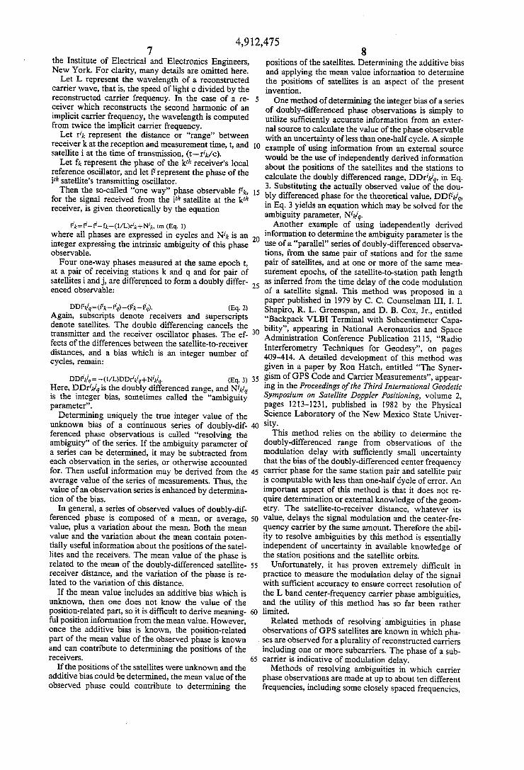
Serving to illustrate an exemplary embodiment of the invention are the drawings wherein like reference nu merals represent like parts: FIG. 1 illustrates a system for determining orbits of
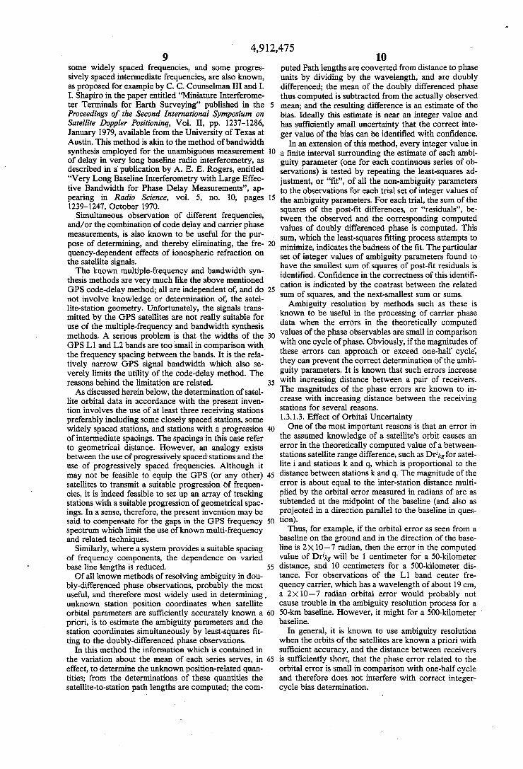
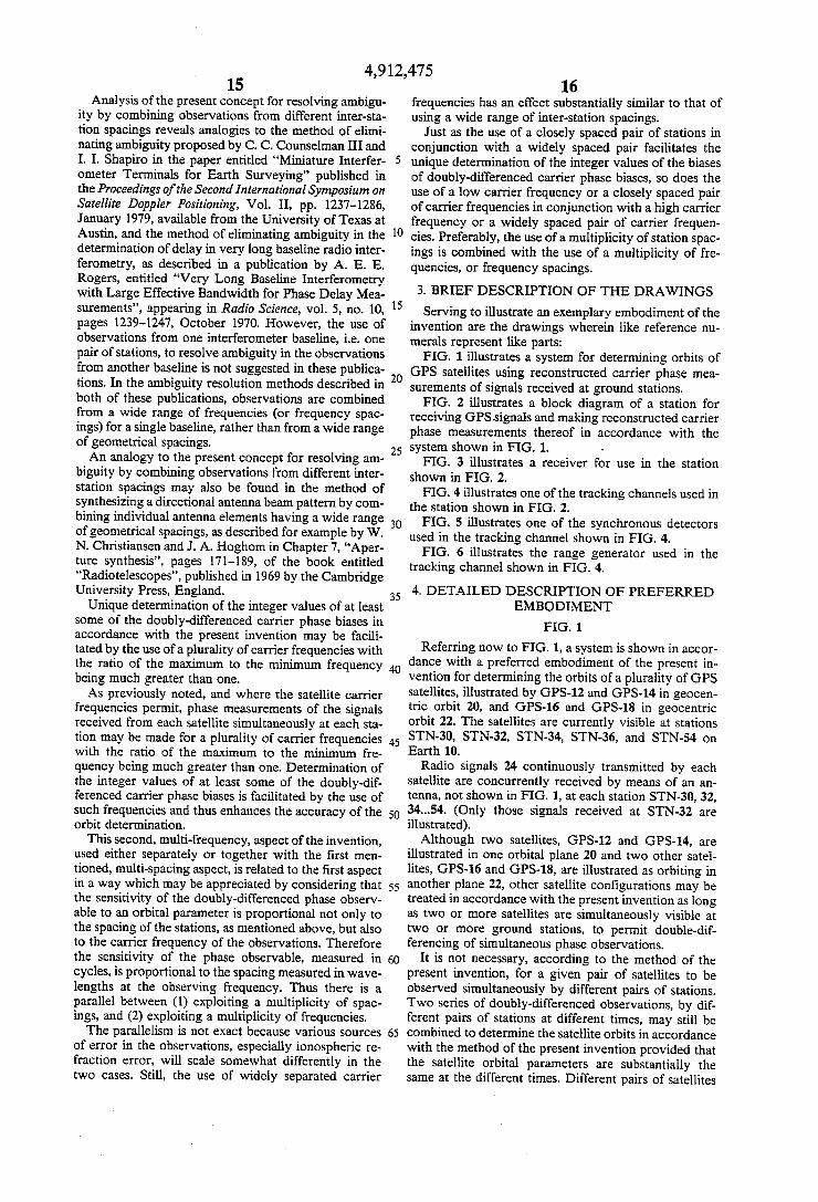
GPS satellites using reconstructed carrier phase mea surements of signals received at ground stations. FIG. 2 illustrates a block diagram of a station for
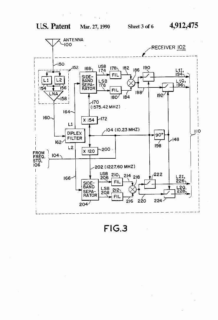
receiving GPS signals and making reconstructed carrier phase measurements thereof in accordance with the system shown in FIG. 1. FIG. 3 illustrates a receiver for use in the station
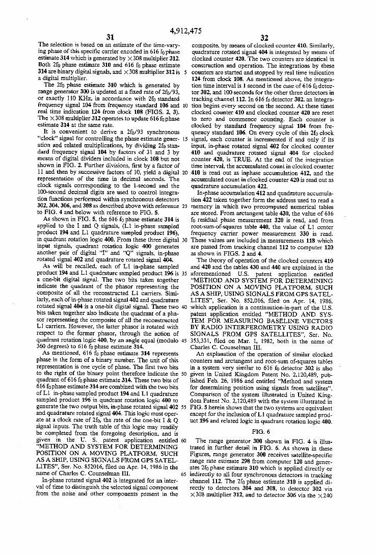
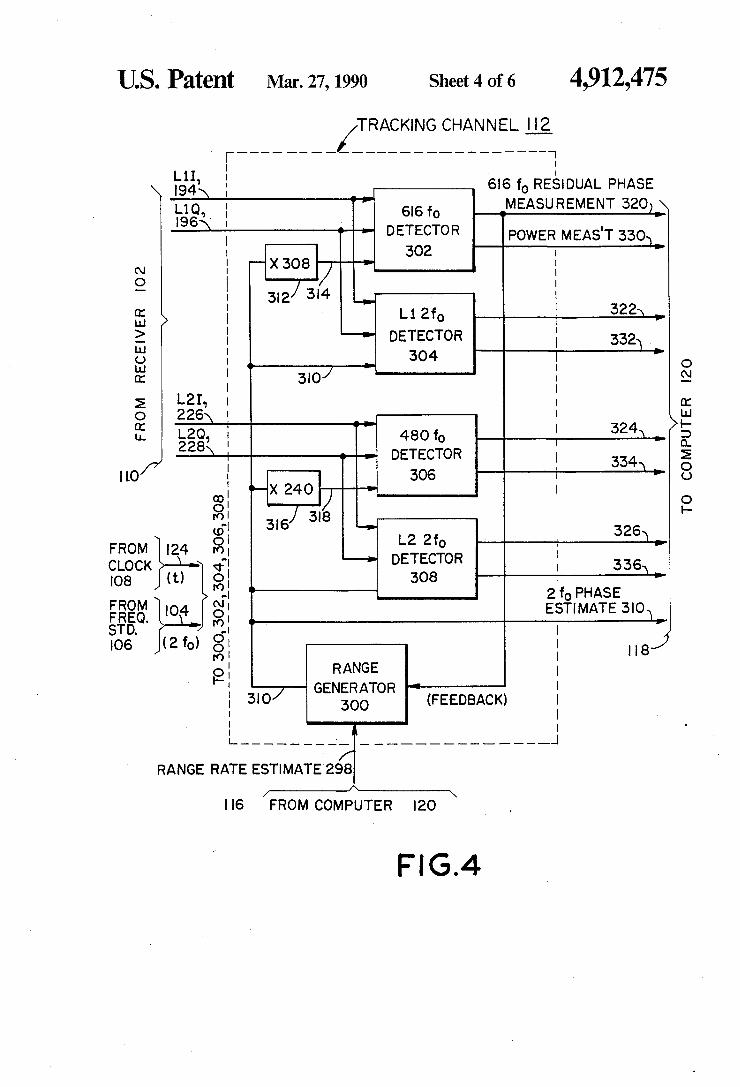
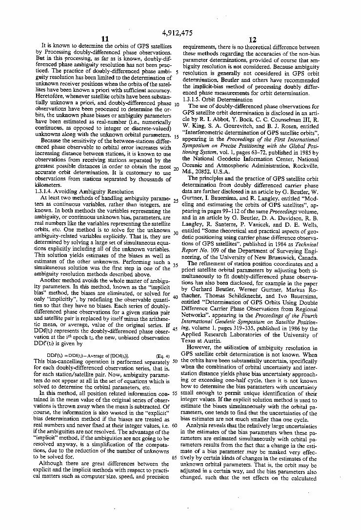
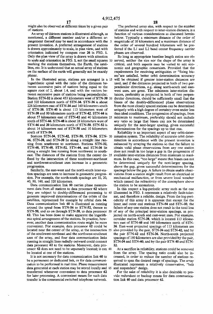
shown in FIG. 2. FIG. 4 illustrates one of the tracking channels used in
the station shown in FIG. 2. FIG. 5 illustrates one of the synchronous detectors
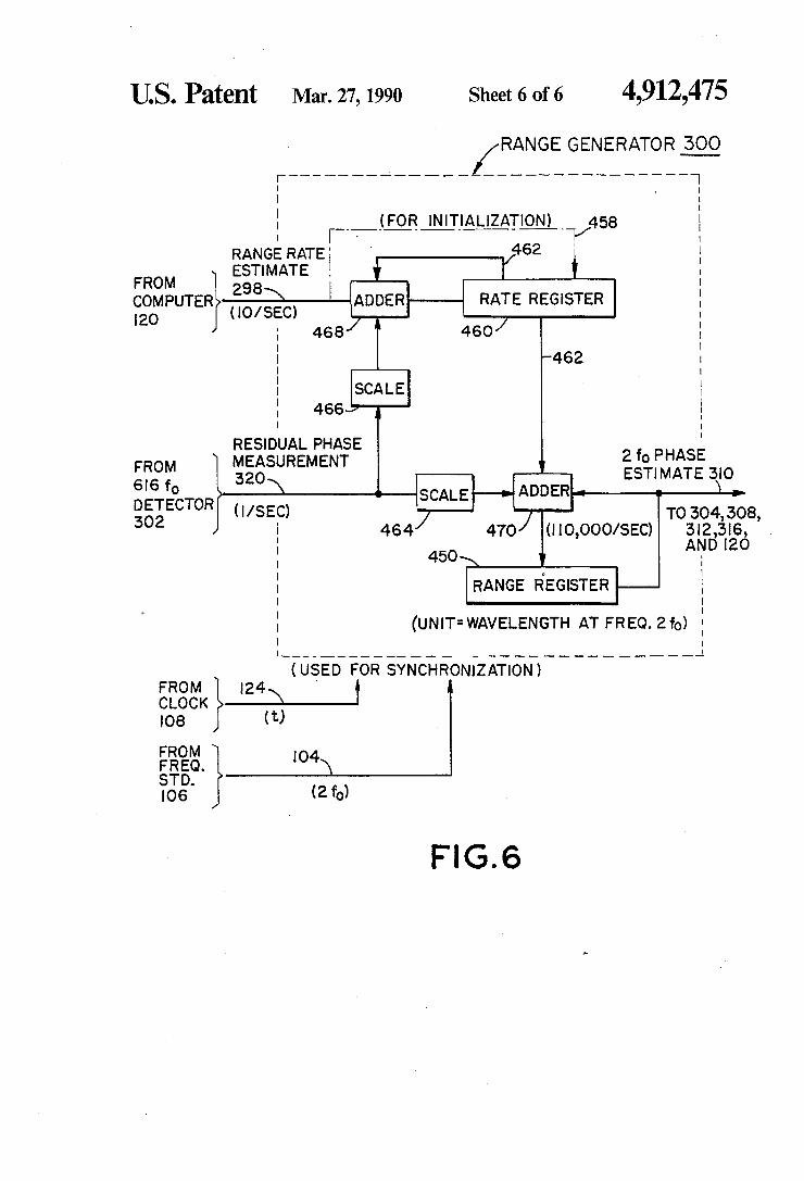
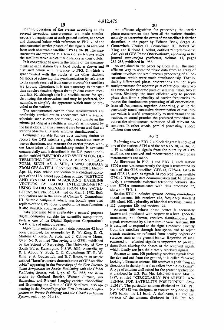
used in the tracking channel shown in FIG. 4. FIG. 6 illustrates the range generator used in the
tracking channel shown in FIG. 4.
4. DETAILED DESCRIPTION OF PREFERRED EMBODIMENT
FIG. 1
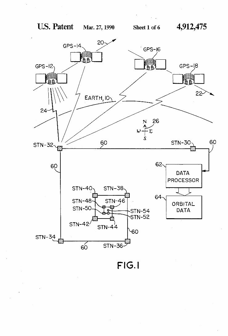
Referring now to FIG. 1, a system is shown in accor dance with a preferred embodiment of the present in vention for determining the orbits of a plurality of GPS satellites, illustrated by GPS-12 and GPS-14 in geocen~ tric orbit 20, and GPS-16 and GPS-18 in geocentric orbit 22. The satellites are currently visible at stations STN-30, STN-32, STN-34, STN-36, and STN-54 on Earth 10. Radio signals 24 continuously transmitted by each
satellite are concurrently received by means of an an tenna, not shown in FIG. 1, at each station STN-30, 32, 34...54. (Only those signals received at STN-32 are illustrated). Although two satellites, GPS-12 and GPS-14, are
illustrated in one orbital plane 20 and two other satel lites, GPS-16 and GPS-18, are illustrated as orbiting in another plane 22, other satellite con?gurations may be treated in accordance with the present invention as long as two or more satellites are simultaneously visible at two or more ground stations, to permit double-dif ferencing of simultaneous phase observations.
It is not necessary, according to the method of the present invention, for a given pair of satellites to be observed simultaneously by different pairs of stations. Two series of doubly-differenced observations, by dif ferent pairs of stations at different times, may still be combined to determine the satellite orbits in accordance with the method of the present invention provided that the satellite orbital parameters are substantially the same at the different times. Different pairs of satellites
4,912,475 17
might also be observed at different times by a given pair of stations. An array of thirteen stations is illustrated although, as
mentioned, a different number and/or a different ar rangement thereof may be used in accordance with the present invention. A preferred arrangement of stations is drawn approximately to scale, in plan view, and with orientation indicated by compass rose 26 in FIG. 1. Only the plan view of the array is drawn with attention to scale and orientation in FIG. 1, not the small squares marking the stations themselves, the Earth, the satel lites, etc. It is understood that an actual array of stations on the surface of the earth will generally not be exactly planar.
In the illustrated array, stations are arranged in a logarithmic spiral with the ratio of the distances be tween successive pairs of stations being equal to the square root of 2, about 1.4, and with the vectors be tween successive pairs of stations being perpendicular. Station STN-32 is about 453 kilometers west of STN-30 and 320 kilometers north of STN-34. STN-36 is about 226 kilometers east of STN-34 and 160 kilometers south of STN-38. STN-40 is about 113 kilometers west of STN-38 and 80 kilometers north of STN-42. STN-44 is about 57 kilometers east of STN-42 and 40 kilometers south of STN-46. STN-48 is about 28 kilometers west of STN-46 and 20 kilometers north of STN-SO. STN-52 is about 14 kilometers east of STN-50 and 10 kilometers south of STN-54.
Stations STN-34, STN-42, STN-50, STN-54, STN 46, STN-38, and STN-30 lie along a straight line run ning from southwest to northeast. Stations STN-32, STN-40, STN-48, STN-SZ, STN-44, and STN-36 lie along a straight line running from northwest to south east. The distances of the stations from the center de fined by the intersection of these southwest-northeast and northwest-southeast axes increase in a geometric progression.
Similarly, the east-west and the north-south inter-sta tion spacings are seen to increase in geometric progres sion. For example, the north-south spacings are 10, 20, 40, 80, 160, and 320 kilometers. Data communication link 60 carries phase measure
ment data from all stations to data processor 62 where they are subject to doubly-differenced processing to generate improved determinations of the orbits of the satellites, represented for example by orbital data 64. Data communication link 60 is illustrated as running around the spiral from STN-54 to STN-52, thence to STN-50, and so on through STN-30, to data processor 62. This has been done to make apparent the logarith mic spiral arrangement of the stations. In practice, how ever, another data communication route might be more convenient. For example, data processor 62 could be located near the center of the array, at the intersection of the southwest-northeast and the northwest-southeast axes of the array, and four data communication links running in straight lines radially outward could connect data processor 62 to the stations. Moreover, data pro cessor 62 does not need to be separately located; it can be located at one of the stations.
It is not necessary for data communication link 60 to be a permanent or dedicated link, or for data communi cation to be performed in real time. Phase measurement data generated at each station may be stored locally and transferred whenever convenient to data processor 62 for later processing. A convenient means for such data transfer is the commercial switched telephone network.
20
25
40
45
60
65
18 The preferred array size, with respect to the number
of stations and with respect to inter-station distance, is a function of various considerations as discussed herein below. Typically a minimum distance of the order of magnitude of 10 kilometers and a maximum distance of the order of several hundred kilometers will be pre ferred if the L1 and L2 band center frequency carrier phases are observed. So long as appropriate baseline length ratios are ob
served, neither the size nor the shape of the array is critical, and both aspects may be varied to suit eco nomic and geographic constraints. Provided that the requirements for resolving ambiguities or “?xing bia ses”are satis?ed, better orbit determination accuracy will be obtained if greater inter-station distances are used, and if the distances projected in both of two per pendicular directions, e.g. along north-south and east west axes, are great. The minimum inter-station dis tances, preferably as projected in both of two perpen dicular directions, should be sufficiently small that the biases of the doubly-differenced phase observations from the most closely spaced stations can be determined uniquely with a high degree of certainty even under less than ideal conditions. The progression of spacings, from minimum to maximum, preferably should not include any ratio so large that biases can not be determined uniquely for the next-larger spacing, given successful determinations for the spacings up to that one.
Reliability is an important aspect of any orbit-deter mination system. The reliability of accurate orbit deter mination in accordance with the present invention is enhanced by arraying the stations so that the failure to obtain valid phase observations from any one station does not result in too large a gap in the progression of available inter-station distances from minimum to maxi mum. In this case, “too large” means that biases can not be determined uniquely for the next-larger spacing, above the gap, given successful determinations for the spacings below the gap. A failure to obtain usable obser vations from a station might result from an electrical or mechanical malfunction, or from severe local weather which caused the refractivity of the atmosphere above the station to be anomalous.
In this respect a log-periodic array such as the one illustrated in FIG. 1 represents a relatively fault-toler ant, and therefore a reliable, design. From the log-peri odicity of this array it is apparent that except for the inner and outer end stations STN-54 and STN-30, the failure of any one station does not result in the total loss of any of ‘the principal inter-station spacings, as pro jected on north-south and east-west axes. For example, consider station STN-38, which is located 113 kilome ters east of STN-40 and 160 kilometers north of STN 36. East-west projected spacings of 113 kilometers are also provided by the pair, STN-34 and STN-42, and by the pair STN-42 and STN-36. North-south projected spacings of 160 kilometers are also provided by the pair, STN-34 and STN-40, and by the pair STN-40 and STN 32. At a sacri?ce in reliability, stations could be removed
from the array. The spacing ratio could also be in creased, in order to reduce the number of stations re quired to span the desired range of spacings. The array illustrated represents a relatively conservative, “belt and suspenders” design. For the sake of reliability it is also desirable to pro
vide redundant or backup means for data communica tion link 60 and data processor 62.
4,912,475 19
During operation of the system according to the present invention, measurements are made simulta neously by equipment at each ground station, as shown and discussed below with reference to FIG. 2, of the reconstructed carrier phases of the signals 24 received from each observable satellite GPS 12, 14, 18. The mea surements are repeated at a series of such times while the satellites move substantial distances in their orbits.
It is convenient to govern the timing of the measure ments at each station by a local clock, as shown and discussed below with reference to FIG. 2, which is synchronized with the clocks at the other stations. Methods of achieving this synchronization by reference to the signals received from one or more of the satellites are known. Therefore, it is not necessary to transmit time synchronization signals through data communica tion link 60, although this is a possible means for syn chronizing the observations and may be preferred, for example, to simplify the apparatus which must be pro vided at the stations. The reconstructed carrier phase measurements are
preferably carried out in accordance with a regular schedule, such as once per minute, every minute on the minute (as long as a satellite is visible), as indicated by the local clock. In this manner it may be ensured that all stations observe all visible satellites simultaneously. Equipment suitable for use at a tracking station to
receive the GPS satellite signals, reconstruct carrier waves therefrom, and measure the carrier phases with out knowledge of the modulating codes is available commercially and is described in the US. patent appli cation entitled “METHOD AND SYSTEM FOR DE— TERMINING POSITION ON A MOVING PLAT FORM, SUCH AS A SHIP, USING SIGNALS FROM GPS SATELLITES”, Ser. No. 852016, ?led on Apr. 14, 1986, which application is a continuation-in part of the US. patent application entitled “METHOD AND SYSTEM FOR MEASURING BASELINE VECTORS BY RADIO INTERFEROMETRY USING RADIO SIGNALS FROM GPS SATEL LITES”, Ser. No. 353,331, ?led on Mar. 1, 1982. Both applications are in the name of Charles C. Counselman III. Suitable equipment which uses locally generated replicas of the GPS codes to perform the same functions is also available commercially. Data processor 62 is preferably a general purpose
digital computer suitable for scientific computation, such as one of the Digital Equipment Corporation’s VAX series of minicomputers. Algorithms suitable for use in data processor 62 have
been described, for example, by R. W. King, E. G. Masters, C. Rizos, A. Stolz, and .T. Collins in Mono graph No. 9, entitled “Surveying with GPS”, published by the School of Surveying, The University of New South Wales, Kensington, N.S.W. 2033, Australia; by R. I. Abbot, Y. Bock, C. C. Counselman III, R. W. King, S. A. Gourevitch, and B. J. Rosen, in an article entitled “Interferometric determination of GPS satellite orbits” appearing in the Proceedings of the First Interna tional Symposium on Precise Positioning with the Global Positioning System, vol. 1, pp. 63-72, 1985; and in an article by Gerhard Beutler, Werner Gurtner, Ivo Bauersima, and Richard Langley entitled “Modelling and Estimating the Orbits of GPS Satellites” also ap pearing in the Proceedings of the First International Sym posium on Precise Positioning with the Global Positioning System, vol. 1, pp. 99-112.
20
25
50
55
60
65
20 An ef?cient algorithm for processing the carrier
phase measurement data from all the stations simulta neously to determine the orbits of the satellites is further described in the paper by Yehuda Bock, Sergei A. Gourevitch, Charles C. Counselman III, Robert W. King, and Richard I. Abbot, entitled “Interferometric Analysis of GPS Phase Observations”, appearing in the journal manuscripta geodaetica, volume 11, pages 282-288, published in 1986. As explained in the paper by Bock et al., the most
efficient way to combine phase data from an array of stations involves the simultaneous processing of all ob servations which were made simultaneously. That is, doubly-differenced phase observations are not sepa rately processed for separate pairs of stations, taken two at a time, or for separate pairs of satellites, taken two at a time. Similarly, the 'most efficient way to process phase data from a plurality of carrier frequencies in volves the simultaneous processing of all observations, from all frequencies, together. Accordingly, while the previously noted successive determination of bias inte ger values is useful conceptually to understand the in vention, in actual practice the preferred procedure in volves the simultaneous estimation of all relevant pa rameters. In other words, parallel processing is more efficient than serial.
FIG. 2
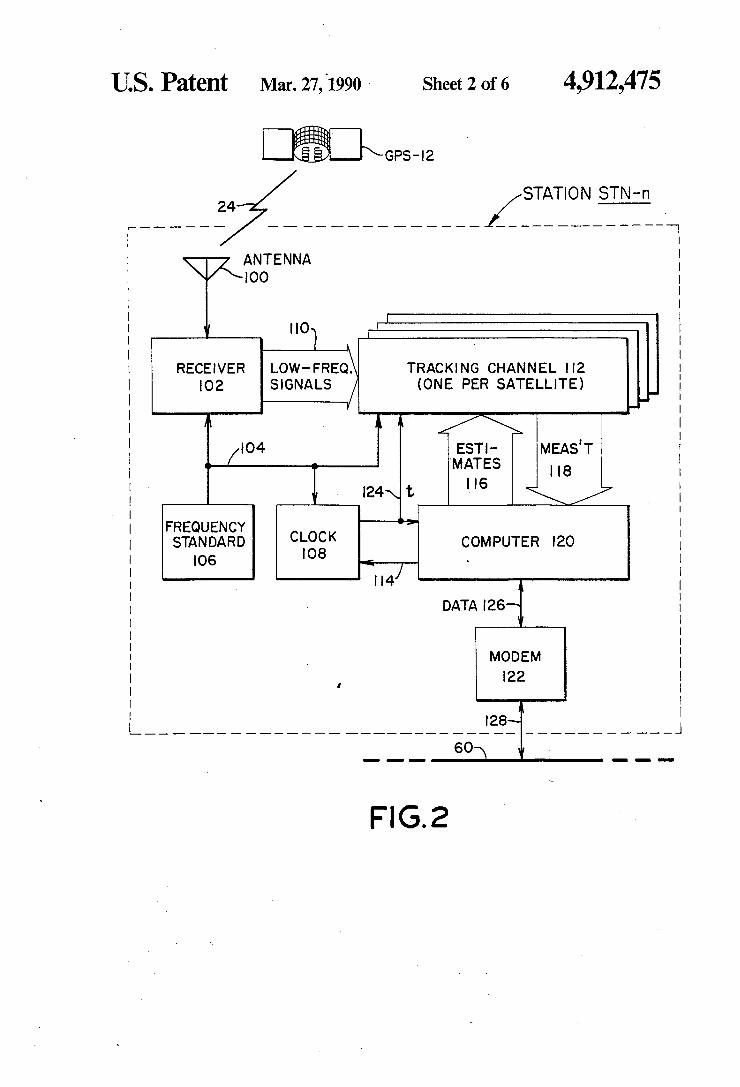
Referring now to FIG. 2, a block diagram is shown of one of the stations STN-n of the set STN 30, 32, 34, 36,
54 at which the signals from the plurality of GPS satellites are received and reconstructed carrier phase measurements are made. As illustrated in FIG. 1 and FIG. 2, each station
STN-n receives concurrently the signals transmitted by each of the GPS satellites GPS-l2, GPS-14, GPS-16 and GPS-18, such as signals 24 received from satellite GPS-12. Through data communication link 60, illustra tively a commercial switched telephone network, sta tion STN-n communicates with data processor 62, shown in FIG. 1.
Station STN-n includes upward looking omni-direc tional antenna 100, receiver 102, frequency standard 106, clock 108, a plurality of identical tracking channels 112, computer 120, and modem 122. Antenna 100, whose phase center is accurately
known and positioned with respect to a local geodetic monument, not shown, receives simultaneously the signals transmitted by all satellites in view. Antenna 100 is designed to respond to the signals received directly from the satellites through free space, and to reject signals scattered or reflected from nearby objects or surfaces such as the ground below. Rejection of such scattered or re?ected signals is important to prevent them from altering the phases of the received signals which ideally are just the directly received signals.
Because antenna 100 preferably receives signals from the sky and not from the ground, it is called “upward looking”. Because antenna 100 receives signals from all directions in the sky, it is also called “omnidirectional”. A type of antenna well suited for the present application is disclosed in US. Pat. No. 4,647,942 issued Mar. 3, 1987, entitled “CIRCULARLY POLARIZED AN TENNA FOR SATELLITE POSITIONING SYS TEMS”. The particular antenna disclosed in US. Pat. No. 4,647,942 was designed to receive only one of the GPS bands, the L1 band. A dual-band, L1 and L2, version of the antenna disclosed in US. Pat. No.
4,912,475 21
4,647,942 is available commercially as the antenna of the MACROMETER II TM Interferometric Surveying System. MACROMETER II is a trademark of Aero Service Division, Western Geophysical Company of America. Antenna 100 is preferably a MACROME TER II antenna or an equivalent.
In the system illustrated in FIG. 2, the relative-posi tion or “baseline” vectors between the phase centers of the antennas at all of the stations, and also the position vector of the phase center of each antenna with respect to the center of mass of the earth, are determined a priori, by known methods, and preferably with better fractional accuracy than is desired for the determina tions of the satellite orbits. Errors in the presumed knowledge of these vectors will cause errors in the orbit determinations. However, as discussed above with ref erence to the paper by Gerhard Beutler, Werner Gurt ner, Markus Rothacher, Thomas Schildknecht, and Ivo Bauersima, entitled “Determination of GPS Orbits Using Double Difference Carrier Phase Observations from Regional Networks”, appearing in the Proceedings of the Fourth International Geodetic Symposium on Satel lite Positioning, volume 1, pages 319-335, published in 1986 by the Applied Research Laboratories of the Uni versity of Texas at Austin, it is possible to re?ne the position vectors of the stations simultaneously with the satellite orbits. If this is to be done, appropriate a priori covariances should be assigned to the uncertain station position coordinates. A composite of the signals simultaneously received
from the plurality of satellites by antenna 100 is applied to receiver 102 which converts the signals from the L1 and L2 bands of frequencies at which the signals are received, to low frequencies at which the operations of carrier reconstruction, phase measurement and tracking are more conveniently performed. Frequency down conversion operations are performed within receiver 102 as disclosed in detail hereinbelow with reference to FIG. 3, by heterodyning the received signals with local oscillator signals. The oscillator signals are synthesized by coherent multiplication of standard frequency signal 104 provided to receiver 102 by frequency standard 106. Carrier reconstruction is also performed within receiver 102. As further disclosed with reference to FIG. 3, a composite of reconstructed carrier compo nents, each related in phase and frequency to a carrier implicit in the composite of spread spectrum signals received by antenna 100, is formed in receiver 102. The reconstructed carrier composite is sampled and the result, in synchronous digital form, is carried by bus 110 to a plurality of identical tracking channels 112. Bus 110 includes separate data lines for the L1 and the L2 bands. Frequency standard 106 is a stable reference stan
dard, such as a commercially available cesium atomic beam resonator controlled oscillator. It has spectral
5
20
25
45
purity sufficient to permit coherent multiplication to L I band, and long term stability and accuracy to permit accurate time-keeping. Standard frequency signal 104 from frequency standard 106 has a frequency equal to 2 f(), or 10.23 MHz.
In addition to being applied to receiver 102, standard frequency signal 104 from frequency standard 106 is applied to and governs the rate of clock 108. As dis closed in detail hereinbelow with reference to FIGS. 3, 4, 5, and 6, clock 108 counts cycles of standard fre quency signal 104 to generate real time indication 124 which is applied to and governs the operation of com puter 120 and all of the tracking channels 112. Clock
65
22 108 of tracking station STN-n is synchronized with the clocks of the other tracking stations by means of syn chroniz'ation signal 114 generated by computer 120. (Preferably each station autonomously derives the syn chronization signal.) As mentioned above with refer ence to FIG. 1, synchronization signal 114 may be de rived by any of a variety of known methods, including decoding of the GPS signal modulation by known means, not shown, included in receiver 102 and/ or in one or more of tracking channels 112. The low frequency, digitized, composite of recon
structed carriers output from receiver 102 on bus 110 is applied identically, in parallel, to all of the tracking channels 112 where the phases of the reconstructed carriers are individually measured. One tracking chan nel 112 is assigned to each satellite, and selectively de tects only carriers from its assigned satellite, using satel lite-specific estimates 116 of the time-varying Doppler ‘shift of the signals received from that satellite.
Estimates 116 applied to tracking channels 112 by computer 120 are computed by known methods from a priori information about the satellite orbits and the tracking station position which may conveniently be provided to computer 120 from the central processor 62 via data communication link 60. An alternative source of information about the satellite orbits is the broadcast information which is carried by the satellite signals and which may be read by known methods involving knowledge of the GPS codes. Data representing the results of carrier. phase and
related power measurements performed within the tracking channels 112, indicated in FIG. 2 as measure ments 118, are provided to computer 120 which may use these measurements to refine estimates 116 and, generally, to monitor and control the measurement processes conducted within the tracking channels. The measurements 118 are stored in the memory of com puter 120 until it is desired to transfer them to data processor 62 (FIG. 1). The transfer to processor 62 of the measurements 118
and related data such as time tags derived from real time indication 124 from clock 108, as well as other data related to the operation and maintenance of station STN-32, uses modem 122, drop 128 and communication link 60. Data communication link 60 is bidirectional so that
information generated by data processor 62 relating to the satellite signals, such as data representing Predic tions of the frequencies of these signals, may be trans ferred to computer 120 through modem 122 and may be used by computer 120 to control or to aid the measure ment processes. In particular, estimates 116 applied to tracking channels 112 may be derived partially or wholly from data received by computer 120 from data processor 62 via line 60. Computer 120 may also generate the clock synchro
nization signal 114, which is applied to clock 108 in order to initialize real time indication 124, partially or wholly on the basis of data received from data proces sor 62 via line 60. Alternatively, and as mentioned above, the information necessary to synchronize clock 108 with the clocks in all other stations and with a stan dard time such as “GPS” time or Coordinated Univer sal Time, may be wholly or partially derived from the satellite signals received at one of the stations STN-n.
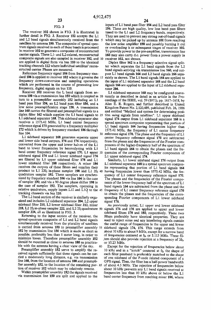
4,912,475 23
FIG. 3
The receiver 102 shown in FIG. 2 is illustrated in further detail in FIG. 3. Receiver 102 accepts the L1 and L2 band signals simultaneously received from the satellites by antenna 100. The composite of spread spec trum signals received in each of these bands is processed in receiver 102 to generate a composite of reconstructed carrier signals. These L1- and L2-related, reconstructed composite signals are also sampled in receiver 102, and are applied in digital form via bus 110 to the identical tracking channels 112 where individual satellites’ recon structed carrier Phases are measured.
Reference frequency signal 104 from frequency stan— dard 106 is applied to receiver 102 where it governs the frequency down-conversion and sampling operations which are performed in the course of generating low frequency, digital signals on bus 110.
Receiver 102 receives the L band signals from an tenna 100 via a transmission line 150 which is coupled in turn to a preampli?er assembly 152 including an L1 band pass ?lter 154, an L2 band pass ?lter 156, and a low noise preampli?cation stage 158. A transmission line 160 carries the ?ltered and preampli?ed signals to a diplex filter 162 which supplies the L1 band signals to L1 sideband separator 168. This sideband separator also receives a 1575.42 MHz, Ll band center frequency reference signal 170 generated by a frequency multiplier 172 which is driven by frequency standard 106 through line 104. L1 sideband separator 168 generates separate upper
and lower side band outputs, 174 and 176 respectively, converted from the upper and lower halves of the L1 bandto lower frequencies by heterodyning with L1 band center frequency reference signal 170. L1 upper sideband signal 174 and Ll lower sideband signal 176 are ?ltered by Ll upper sideband ?lter 178 and L1 lower sideband ?lter 180 respectively. A mixer 186 receives the outputs of these ?lters and supplies their product to L1 22f0 in~phase sampler 190 and L1 2f0 quadrature sampler 192. These samplers are synchro nized by frequency standard 106 via line 104 in the case of sampler 190, and via a 90 degree phase shifter 198 in the case of sampler 192. The samplers, operating in relative quadrature, supply inputs LlI and LlQ to the tracking channels via bus 110. ' ‘
The L2 band section of the receiver is similarly orga nized and includes L2 sideband separator 204, L2 upper sideband ?lter 210, L2 lower sideband ?lter 212, mixer 218, L2 211) in-phase sampler 222, and L2 2f0 quadrature sampler 224, all as illustrated in FIG. 3.
Returning to the input section of the receiver, the spread-spectrum composite of L1 and L2 band signals simultaneously received from the plurality of satellites is carried from antenna 100 to preampli?er assembly 152 by transmission line 150 which is made as short as possible, preferably less than 1 meter long, in order to minimize losses. Therefore preampli?er assembly 152 should be mounted as close to antenna 100 as practica ble with the antenna having a clear view of the sky.
Preampli?er assembly 152 serve to amplify the re ceived signals sufficiently that these signals can be car ried a moderately long distance, eg via transmission line 160, from the location of antenna 100 and preampli ?er assembly 152, to the location of the remaining por tion of receiver 102 which may be relatively remote.
Within preampli?er assembly 152 the signals received via transmission line 150 are split and applied to the
20
25
30
35
40
45
50
55
60
65
24 inputs of Ll band pass ?lter 154 and L2 band pass ?lter 156. These are high quality, low loss band pass ?lters tuned to the L1 and L2 frequency bands, respectively. They are used to prevent any strong out~of-band signals which may be picked up by antenna 100 from reaching the low noise ampli?er 158 and possibly burning it out or overloading it or subsequent stages of receiver 102. To provide power to the pre-ampli?er, transmission line 160 may also carry dc. power from a power supply in receiver 102, not shown.
Diplex ?lter 162 is a frequency selective signal split ter which separates the Ll band signals from the L2 band signals arriving via transmission line 160, and out puts L1 band signals 164 and L2 band signals 166 sepa rately as shown. The L1 band signals 164 are applied to the input of L1 sideband separator 168 and the L2 band signals 166 are applied to the input of L2 sideband sepa rator 204. L1 sideband separator 168 may be con?gured conve
niently as described in detail in an article in the Pro ceedings of the IEEE, vol. 59 (1971), pp. 1617-1618, by Alan E. E. Rogers, and further described in United Kingdom Patent No. 2,120,489, published Feb. 26, 1986 and entitled “Method and system for determining posi tion using signals from satellites”. L1 upper sideband signal 174 output from L1 sideband separator 168 is a spread spectrum composite representing that portion of L1 band signals 164 having frequencies higher than 1575.42 MHz, the frequency of L1 center frequency reference signal 170. The phase and the frequency of L1 center frequency reference signal 170 are subtracted from the phases and the frequencies of the Fourier com ponents of the higher-frequency half of the spectrum of L1 band signals 164 to obtain the phases and the fre quencies of the corresponding Fourier components of L1 upper sideband signal 174.
Similarly, L1 lower sideband signal 176 output from L1 sideband separator 168 is a spread spectrum compos ite representing that portion of L1 band signals 164 having frequencies lower than 1575.42 MHz, the fre quency of L1 center frequency reference signal 170. The phases and the frequencies of the Fourier compo nents of the lower-frequency half of the spectrum of L1 band signals 164 are subtracted from the phase and the frequency of L1 center frequency reference signal 170 to obtain the phases and the frequencies of the corre sponding Fourier components of L1 lower sideband signal 176. As previously noted, Ll upper and lower sideband
signals 174 and 176 are applied to upper and lower sideband ?lters 178 and 180, respectively. These two ?lters preferably have identical properties. They are used to reject noise and any interfering signals outside the useful range of frequencies in the upper and lower sideband signals 174, 176. This range extends from about 10 kHz to about 9 MHz, except for a narrow band of frequencies centered at f0, or 5.115 MHz. These ?l ,ters should also provide rejection at a frequency of 2f0, or 10.23 MHz.
Except for the rejection of frequencies below about 10 kHz and in a “notch” centered at f@, the shape of each ?lter passband is preferably matched to the shape of one sideband of the P-code related component of a GPS signal. Thus, the ?lter has a half-power bandwidth of about 4.5 MHz. The rejection of frequencies below about 10 kHz prevents any L1 band signals received at frequencies less than 10 kHz above or below the L1 band center frequency from reaching mixer 186, where