Embed Size (px)
Citation preview

Technicolor COM2000 Integrator’s Manual

w w w . t e c h n i c o l o r . c o m / m c s
Page 2
Table of Contents 1 Introduction ............................................................................................................................... 10
2 COM2000 Product Description ................................................................................................. 11
3 Definitions ................................................................................................................................. 13
4 Mechanical Overview ............................................................................................................... 16
4.1 COM360 Chassis....................................................................................................................... 16
4.2 COM46 Card ............................................................................................................................. 18
4.3 COM46-FLX Card .................................................................................................................... 20
4.4 QAM6 Overview ....................................................................................................................... 21
5 Pre-Installation .......................................................................................................................... 23
5.1 Training and Support ................................................................................................................. 23
5.2 Required Tools .......................................................................................................................... 23
5.3 Pre-Installation Site Requirements ............................................................................................ 24
5.4 Channel Lineup ......................................................................................................................... 25
5.5 External Video Sources ............................................................................................................. 25
5.6 TV Compatibility ...................................................................................................................... 25
5.7 Installation Guidelines ............................................................................................................... 26
5.8 DIRECTV Activation ................................................................................................................ 27
6 Getting Started ........................................................................................................................... 28
6.1 Assembly ................................................................................................................................... 28
6.2 Setting up Multiple Chassis....................................................................................................... 29
7 The COM2000 Web Interface ................................................................................................... 31
7.1 The Overview Page ................................................................................................................... 32
7.2 Discover Page ............................................................................................................................ 36
7.3 Explanation of Discover Page Fields ........................................................................................ 37
7.4 The Tune Command .................................................................................................................. 38
7.5 Advanced Tune Screen .............................................................................................................. 39
7.6 COM46 Informational Status .................................................................................................... 42
7.7 COM46 LED Control Feature ................................................................................................... 44
7.8 COM46 CAM Log Data ............................................................................................................ 44
7.9 COM46 Software Reset ............................................................................................................ 46
7.10 COM46 File Transfer Utility ............................................................................................. 46
7.11 COM46 User Configuration Options ................................................................................. 48
7.12 COM46 “Direct Tune” Feature .......................................................................................... 50

w w w . t e c h n i c o l o r . c o m / m c s
Page 3
7.13 Remote Access Feature ...................................................................................................... 50
7.14 Using the VidPlay Feature ................................................................................................. 51
7.15 Using the COM46 “Simulcrypt” Feature ........................................................................... 51
7.16 Using the COM46 REST Feature ...................................................................................... 52
7.17 Displaying COM2000 Status ............................................................................................. 52
7.18 Pairing Info ........................................................................................................................ 53
7.19 Tune all Command ............................................................................................................. 56
7.20 Refreshing the COM2000 Display..................................................................................... 58
7.21 SysInfo ............................................................................................................................... 59
7.22 HealthInfo .......................................................................................................................... 60
7.23 Syslogs ............................................................................................................................... 62
8 Electronic Program Guide and PSIP ......................................................................................... 63
8.1 EPG Overview ........................................................................................................................... 63
8.2 Getting Started with EPG .......................................................................................................... 65
8.3 Configuring the EPG ................................................................................................................. 69
8.4 Logo upload ............................................................................................................................... 71
9 Welcome Screen ........................................................................................................................ 72
9.1 Image creation ........................................................................................................................... 72
9.2 Uploading Welcome screens to COM 2000 .............................................................................. 74
10 QAM6 ........................................................................................................................................ 79
10.1 QAM6 Overview ............................................................................................................... 79
10.2 QAM6 Settings and Configuration .................................................................................... 80
10.3 QAM LOG ......................................................................................................................... 83
11 Software Upgrade Procedures ................................................................................................... 84
11.1 Preparing for a Software Upgrade .................................................................................... 84
11.2 Using the COM46 as a TFTP server ................................................................................. 85
11.3 Performing Software Upgrades.......................................................................................... 86
11.4 Upgrading a COM46-FLX from SD to HD ....................................................................... 89
11.5 Upgrading QAM6 Software .............................................................................................. 90
11.6 QAM6 Reset ...................................................................................................................... 91
12 Modulation of External Video Sources ..................................................................................... 92
12.1 Overview ............................................................................................................................ 92
12.2 Source Options ................................................................................................................... 92
13 Diagnostics ................................................................................................................................ 93

w w w . t e c h n i c o l o r . c o m / m c s
Page 4
13.1 Indicator Lights .................................................................................................................. 93
13.2 Power Supply Issues .......................................................................................................... 93
13.3 System Startup ................................................................................................................... 94
13.4 Normal Operation .............................................................................................................. 96
13.5 Software Upgrade .............................................................................................................. 97
13.6 Network Connectivity Indicators ....................................................................................... 98
14 Troubleshooting ........................................................................................................................ 99
14.1 Testing Video without Pro:Idiom Encryption.................................................................... 99
14.2 Fixing an Unresponsive Card........................................................................................... 102
15 Preventing Pro:Idiom Key Loss .............................................................................................. 104
15.1 PID Mapping at the COM46 Receiver............................................................................. 104
15.2 Best Practices to Avoid Key Loss .................................................................................... 105
15.3 EdgeQAM PID remapping .............................................................................................. 106
16 Technicolor ATSC-8 Users Guide .......................................................................................... 109
16.1 Introduction ...................................................................................................................... 110
16.2 Over-the-Air Broadcasts .................................................................................................. 110
16.3 Advantages of ATSC Broadcast Channels ...................................................................... 110
16.4 Getting Started ................................................................................................................. 111
16.5 Site Survey ....................................................................................................................... 111
16.6 ATSC-8 Programming ..................................................................................................... 113
16.7 ATSC-8 Installation ......................................................................................................... 114
16.8 Connection to the COM2000 ........................................................................................... 115
16.9 Check / Update the ATSC-8 firmware version ................................................................ 117
16.10 HDHomeRun Tech Configuration Utility ....................................................................... 117
16.11 Configuring the ATSC-8.................................................................................................. 119
16.12 Discover the IP Addresses of the ATSC Tuner Modules ................................................ 119
16.13 Changing the IP Addresses of the Tuners ........................................................................ 120
16.14 Loading Data from the Tuners ......................................................................................... 122
16.15 Changing the Tuning Table ............................................................................................. 122
16.16 QUERY Command .......................................................................................................... 124
16.17 Adding PSIP Data for ATSC-8 Channels ........................................................................ 125
17 Addendums .............................................................................................................................. 126
17.1 Open Software Notification ............................................................................................. 126

w w w . t e c h n i c o l o r . c o m / m c s
Page 5
Table of Figures
FIGURE 1 - COM2000 SYSTEM OVERVIEW ....................................................................................... 12
FIGURE 2 - COM2000 FRONT VIEW .................................................................................................. 16
FIGURE 3- COM2000 REAR VIEW ..................................................................................................... 17
FIGURE 4 - COM46 CARD ................................................................................................................. 18
FIGURE 5 - COM46 FLEX CARD ........................................................................................................ 20
FIGURE 6 - QAM6 CARD ................................................................................................................... 21
FIGURE 7- QAM6 INSTALLATION ...................................................................................................... 22
FIGURE 8 - INSTALLATION OF THE QAM6 ......................................................................................... 28
FIGURE 9 - SECURING THE QAM6 IN THE COM360 .......................................................................... 28
FIGURE 10 - COM36 REAR PANEL REMOVAL ................................................................................... 29
FIGURE 11 - CHASSIS ID DIPSWITCH ................................................................................................. 29
FIGURE 12 - DIPSWITCH SETTINGS FOR MULTIPLE CHASSIS .............................................................. 30
FIGURE 13 - COM2000 USER INTERFACE INTRODUCTION PAGE ....................................................... 31
FIGURE 14 - COM2000 OVERVIEW PAGE .......................................................................................... 32
FIGURE 15 – ENCRYPTION SETTINGS ................................................................................................. 33
FIGURE 16 - CHANNEL DROP DOWN MENU ....................................................................................... 34
FIGURE 17 - OUTPUT MODE ............................................................................................................... 34
FIGURE 18 - MAJOR/MINOR CH OR IP AND PORT SETTINGS .............................................................. 35
FIGURE 19 - BITRATE DISPLAY .......................................................................................................... 35
FIGURE 20 - SNR AND SIGNAL STRENGTH ......................................................................................... 35
FIGURE 21 - COM46 DISCOVER PAGE ............................................................................................... 36
FIGURE 22 - COM46 BASIC TUNE SCREEN ........................................................................................ 38
FIGURE 23 - ADVANCED TUNE SCREEN ............................................................................................. 39
FIGURE 24 - "INFO" SECTION OF THE ADVANCED EDIT PAGE ............................................................ 42
FIGURE 25 - NETWORK ID AND FREQUENCY INDEX .......................................................................... 43
FIGURE 26 - LED CONTROL .............................................................................................................. 44
FIGURE 27 - CAM LOG INTERFACE ................................................................................................... 44
FIGURE 28 - CAM LOG REPORT.......................................................................................................... 45
FIGURE 29 - RESET INTERFACE .......................................................................................................... 46
FIGURE 30 - FILE TRANSFER INTERFACE ........................................................................................... 46
FIGURE 31 - USER CONFIG INTERFACE .............................................................................................. 48

w w w . t e c h n i c o l o r . c o m / m c s
Page 6
FIGURE 32 - DIRECT TUNE INTERFACE.............................................................................................. 50
FIGURE 33 - REMOTE ACCESS FEATURE ............................................................................................ 50
FIGURE 34 - VID PLAY ....................................................................................................................... 51
FIGURE 35 - SIMULCRYPT .................................................................................................................. 51
FIGURE 36 - REST ............................................................................................................................. 52
FIGURE 37 - COM2000 DISPLAY PAGE ............................................................................................. 52
FIGURE 38 - COM2000 PAIRING INFO PAGE ..................................................................................... 53
FIGURE 39 - COM46 MULTI CARD UPGRADE ................................................................................... 54
FIGURE 40 - COM46 TUNE ALL ........................................................................................................ 56
FIGURE 41 - COM2000 REFRESH ...................................................................................................... 58
FIGURE 42 - COM46 SYS INFO PAGE ................................................................................................ 59
FIGURE 43 - COM2000 HEALTH INFO PAGE ..................................................................................... 60
FIGURE 44 - SYSLOG EXAMPLE .......................................................................................................... 62
FIGURE 45 - COM2000 EPG PAGE .................................................................................................... 65
FIGURE 46 - COM2000 EPG PAGE (CONFIGURED) ........................................................................... 68
FIGURE 47 - COM46 EPG LOAD RESULT .......................................................................................... 69
FIGURE 48 - GUIDE CHANNEL ............................................................................................................ 70
FIGURE 51 - EPG LOGO CREATION .................................................................................................... 71
FIGURE 50 - GUIDE CHANNEL WITH CUSTOM LOGO .......................................................................... 71
FIGURE 53 - WELCOME SCREEN IMAGE CREATION ............................................................................ 72
FIGURE 52 - USING MICROSOFT PAINT TO SIZE WELCOME SCREEN .................................................... 73
FIGURE 53 - CORRECTLY SIZED WELCOME SCREEN IMAGE ............................................................... 74
FIGURE 54 - DETERMINE CARD TO USE FOR WELCOME SCREEN ........................................................ 74
FIGURE 55 – UPLOAD WELCOME SCREEN FILES TO INTERNAL TFTP ................................................ 75
FIGURE 56 - UPLOAD WELCOME SCREEN IMAGE TO EPG ................................................................. 76
FIGURE 57 - ADDING WELCOME SCREEN TO EPG AND PSIP ............................................................. 77
FIGURE 58 - VERIFY WELCOME SCREEN IS STREAMING ..................................................................... 78
FIGURE 59- QAM6 ............................................................................................................................ 79
FIGURE 60 - QAM6 COMMAND SCREEN ............................................................................................ 81
FIGURE 61 - QAM LOG EXAMPLE ..................................................................................................... 83
FIGURE 62 - COM46 MULTI CARD UPGRADE ................................................................................... 85
FIGURE 63 - COM46 SOFTWARE UPLOAD ......................................................................................... 86

w w w . t e c h n i c o l o r . c o m / m c s
Page 7
FIGURE 64 - ADVANCED EDIT FILE TRANSFER .................................................................................. 87
FIGURE 65 - MULTI CARD COM46 SW UPDATE ............................................................................... 88
FIGURE 66 - MULTI CARD UPGRADE RESULTS .................................................................................. 88
FIGURE 67 - APPLYING A LICENSE FILE TO ENABLE FEATURES ......................................................... 89
FIGURE 68 - UPLOAD QAM6 SOFTWARE ........................................................................................... 90
FIGURE 69 - QAM6 SOFTWARE UPGRADE ......................................................................................... 90
FIGURE 70 - QAM6 SOFTWARE UPGRADE RESULTS ......................................................................... 91
FIGURE 71 - QAM6 RESET AFTER SOFTWARE UPGRADE .................................................................. 91
FIGURE 72 - LED STATES .................................................................................................................. 93
FIGURE 75- LED STARTUP AND OPERATIONAL BEHAVIOR ............................................................... 95
FIGURE 76 - LED BEHAVIOR DURING SOFTWARE UPGRADE ............................................................. 97
FIGURE 75 - NETWORK CONNECTIVITY LEDS ................................................................................... 98
FIGURE 76 - VLC OPEN NETWORK STREAM .................................................................................... 100
FIGURE 77 - OPENING A NETWORK STREAM IN VLC ....................................................................... 100
FIGURE 78 - STREAMING VIDEO WITH VLC ..................................................................................... 101
FIGURE 79 - TFTP MAIN PAGE ........................................................................................................ 102
FIGURE 82 - ENABLING TFTP BOOTP SERVER .............................................................................. 103
FIGURE 81- IMPROPER MAPPING OF OFF AIR CHANNELS ................................................................... 105
FIGURE 82 - CORRECT CHANNEL MAPPING TO PREVENT P.I. KEY LOSS ......................................... 106
FIGURE 83 - HARMONIC SETUP WITH INCORRECT PID MAPPING ..................................................... 107
FIGURE 84 - CORRECT PID REMAPPING ........................................................................................... 108
FIGURE 87 - ATSC-8 BACK PANEL ................................................................................................. 114
FIGURE 88 - ATSC-8 FRONT PANEL ................................................................................................ 114
FIGURE 87 - ATSC CONNECTION DIAGRAM .................................................................................... 116
FIGURE 88 - HDHOMERUN TECH CONFIGURATION UTILITY ........................................................... 117
FIGURE 89 - HDHOMERUN UPGRADE FIRMWARE TAB ................................................................... 117
FIGURE 90 - LOADING FIRMWARE IN TEH HDHOMERUN UTILITY ................................................... 118
FIGURE 91 - HDHOMERUN FIRMWARE LOAD ................................................................................. 118
FIGURE 92 - ACCESSING THE ATSC TAB ......................................................................................... 119
FIGURE 93 - ATSC TUNER DISCOVERY ............................................................................................ 120
FIGURE 96 - CHANGING TUNER IP ADDRESSES ................................................................................ 120
FIGURE 97 - ATSC DISCOVER ......................................................................................................... 121

w w w . t e c h n i c o l o r . c o m / m c s
Page 8
FIGURE 96 - ATSC LOAD FUNCTION ............................................................................................... 122
FIGURE 99 - ATSC TUNE TABLE ..................................................................................................... 123
FIGURE 98 - QUERY COMMAND RESULTS ........................................................................................ 124
FIGURE 99 - EPG AND PSIP PROGRAMMING ................................................................................... 125

w w w . t e c h n i c o l o r . c o m / m c s
Page 9
REVISION RECORD
Revision Date Revision Editor Revision Description
2.1 10/13/15 Angelo Peruch PDF to post
2.2 1/27/17 Angelo Peruch Added Open Software Notification / changed cover page logo

w w w . t e c h n i c o l o r . c o m / m c s
Page 10
1 Introduction This document describes the processes and procedures for configuring a COM2000 system. The
following sections will provide a brief overview of the system hardware, an in-depth guide to the
COM46 user interface, and descriptions of certain system processes. Also included are several
indices that cover common troubleshooting problems.
It is recommended that you read through the entirety of the manual, or at least review the main
sections before working with the system, as it contains some important pointers that may come in
handy during setup and maintenance

w w w . t e c h n i c o l o r . c o m / m c s
Page 11
2 COM2000 Product Description
A COM360 chassis fully populated with COM46 receivers is capable of tuning and transcrypting
up to 48 DIRECTV channels. The satellite signal is tuned and demodulated resulting in a
DIRECTV legacy or MPEG-4 transport stream. This transport stream is then IP-encapsulated
using standard Internet protocols and sent out over the chassis backplane.
The data can be routed to an internal QAM6 modulator for RF output and also to two GIGe
network connections for distribution on an IPTV network or external QAM modulator. The
original DIRECTV broadcast video encoding format is preserved and the output transport stream
is encrypted with the Pro:Idiom or other optional encryption standards.
Multiple COM360 chassis can be “stacked” in order to provide more than 48 output channels. Up
to 16 chassis can be connected in the same system.
The COM46 receiver cards are controlled and managed via an Ethernet connection on the
COM360 chassis. The COM46 card includes a built-in web interface and can be configured using
a web browser. To view high definition video from the COM2000 a TV equipped with decryption
technology must be used. Additionally the COM2000 is compatible with Samsung Link and
Verimatrix DRMs, and Video Propulsion MPEG2 Pro:Idiom edge QAMs. Standard definition
channels may be distributed in-the-clear.
In addition to high quality DIRECTV programming the COM2000 system offers additional
powerful features:
Optional Mediatune 2.0 software upgrade offers switched matrix control capabilities for public
space environments.
Internal “home screen” channels stream direct from the COM2000 system.
An electronic program guide that is fully customizable to system channel lineup and local
programming. PSIP data will pass to televisions and “map” the channels without intervention.
(PSIP interpretation is TV dependent, not all TVs respond to PSIP in the same manner. Test
the TVs before installing.
External content from a variety of sources can be modulated through the COM2000.
Remote monitoring and management through Technicolor web server.
Interfaces with Emergency Alert Systems (EAS). Capable of sending locally originated
streams to all video channels for site specific emergency broadcast. (Only available on
systems utilizing the Technicolor QAM6 modulator).
Optional ATSC-8 tuner facilitates streaming 8 off air channels through the COM2000 system.
Multiple program streams from each off-air channel can add dozens of local channels to your
lineup at no monthly cost to your customer.

w w w . t e c h n i c o l o r . c o m / m c s
Page 12
Refer to Figure 1 below for a diagram illustrating a complete COM2000 system.
Pro:Idiom Enabled
Television
Pro:Idiom encrypted signal to IP Distribution
Network - Multicast IGMP Switches
External QAM
VLAN Router
Local Admin PC
Technicolor
Remote Access
Web Server
Management
Ports 100Mbps GIGe
Ports /
Switch
From Satellite Distribution to
SWiM Switches
External Sources
ATSC-8
Hard Drive
PC / VLC
EAS
ZyCast Media Server
Pro:Idiom Enabled
IP Television
RF signal to COM46 input.
Each COM46 card requires a SWiM 8 input
-55 to -25dBm all transponders Pro:Idiom encrypted
signals to RF Distribution
Figure 1 - COM2000 System Overview

w w w . t e c h n i c o l o r . c o m / m c s
Page 13
3 Definitions Term Definition
Admin PC A PC is required for initial setup and configuration. It is highly recommended to set up remote access to the COM2000 system for monitoring and maintenance post installation. This can be accomplished via several methods: A PC on site, connected to the internet running Team Viewer or a similar remote desktop program. PC will need to be on the same IP subnet as the COM2000 system VPN router set up for remote access via a Virtual Private Network
ATSC Advanced Television Systems Committee. An international organization developing voluntary standards for digital television. Typically used to describe terrestrial off air broadcast TV standards. ATSC Tuner describes a TV capable of receiving digital off-air broadcasts. http://atsc.org/
ATSC-8 This is a device provided by Technicolor to provide ATSC off air television signals to the COM2000. It is configured and controlled through the COM2000 web interface. Depending on configuration it can deliver 8 program channels or 8 complete ATSC8 broadcasts including all sub channels in the carrier.
COM2000 System This describes the Technicolor system consisting of a COM360 chassis, COM46 cards and QAM 6 modulators. Replaced previous product COM1000
COM360 Chassis This device houses the COM46 and QAM 6 components. All video traffic is routed through the two Gigabit Ethernet (GbE) ports on the front of the chassis or to the QAM6 slots. System management and control can be done by connecting a computer to one of the management ports on the front panel of QAM6 cards or the GIGe ports. Replaced previous product version COM200
COM46 and COM46-FLX Cards
The bulk of this manual is dedicated to these cards. They are the means by which the property will be able to receive the desired television programming for their network and control the entire COM2000 system. Replaced previous product version COM24 / Com24-FLEX.
EAS Emergency Alert Systems can be interfaced with the COM2000 to stream emergency notifications to all channels. Similar to this a local message can be created and played via a PC and VLC or a ZyCast Media Server. https://www.fcc.gov/encyclopedia/emergency-alert-system-eas
Edge QAM In a typical installation, the COM46 cards will be configured to stream to a QAM6 modulator. Alternatively the COM46 IP streams can feed an external edge QAM.
GIGe Gigabit Ethernet High speed Ethernet standard for transmitting data at one gigabit per second. All switches in the GIGe (video) network must be rated to pass this level of traffic.
Hard Drive The COM2000 can process content on a hard drive to stream on a video channel.
HD High Definition

w w w . t e c h n i c o l o r . c o m / m c s
Page 14
Hot-swappable The unit or device this term describes may be added to, removed from, or replaced
within the system it is a part of without powering anything down.
MPEG Moving Pictures Experts Group - A working group of ISO/IEC with the mission to develop standards for coded representation of digital audio and video and related data. Most commercial and some residential TVs support MPEG4 standards. All DIRECTV HD signals are MPEG4. Many residential and some older commercial TVs will only support MPEG2 signals and will require transcription from MPEG4 to MPEG2, or the use of a setback box like the Technicolor DCI401MCS. http://mpeg.chiariglione.org/
PC/VLC The COM2000 can accept streaming video from a networked PC running VLC, an open source video software. http://www.videolan.org/vlc/index.html
PID Packet Identification
Pro:Idiom Pro:Idiom is an industry accepted digital rights management encryption technology for video signals broadcast in commercial establishments such as hotels, dormitories and hospitals. All major programmers have accepted Pro:Idiom as an encryption method to secure programming. Only televisions or set-back boxes with built in Pro:Idiom encryption system decoders will be able to decrypt the signal. http://www.zenith.com/wp-content/uploads/2013/05/ProIdiom_Overview_2010-10-08.pdf
Property Distribution Network
This network, set up and maintained by the system operator or property owner, distributes television signals via RF or IP technology. Traditional analog RF plants often are in need of repairs and upgrades before they will pass digital HD programming. RF levels and signal to noise ratios (Modulation Error Rate) should be tested to industry standards. IP systems require technicians proficient in IP switch configurations, specifically multicast networks utilizing Internet Group Management Protocols (IGMP).
PSIP Program and System Information Protocol. Signals included in a digital TV signal that instruct the TV to tune to a specific channel. For example an off-air channel may be broadcast on UHF ch 38 but the station call letters are ch 7. PSIP data instructs the TV to look for ch 7 on UHF38. PSIP data also includes current and future programming information. In a COM2000 system your first RF channel may be 23.1. You can configure PSIP within the COM2000 electronic program guide to map this programming to channel 2. http://www.atscforum.org/
QAM6 Cards A board that installs in the upper left side of a COM360 Chassis. It converts the COM46’s IP-packetized streams to QAM-modulated RF for distribution throughout a property. The board provides up to 12 QAM modulator channels in addition to a 10/100 Ethernet port. The QAM6 base unit outputs 6 QAM channels each capable of carrying 3 HD or 8 SD channels. Units are upgraded via 2 QAM licenses making the unit cost effective for smaller applications. Each QAM channel can carry up to three HD or eight SD video channels. A fully loaded COM2000 system broadcasting 48 HD channels requires 16 QAM channels leaving additional capacity for additional services.

w w w . t e c h n i c o l o r . c o m / m c s
Page 15
Satellite Distribution Network
This network consists of the dish, LNB and associated equipment necessary to provide KA/KU band satellite signals to the COM2000. The COM2000 requires a SWiM 8 signal to each card. It is assumed that installation technicians have adequate expertise and proper test equipment required to install the distribution system to DIRECTV specifications.
SD Standard Definition
SWiM Switch Single Wire Multi-switch – A DIRECTV module used for distribution of satellite signals. Available models support 8,16, of 32 tuners.
SWQAM2 The SWQAM2 is a software key that will enable 2 QAM channels per key on a QAM6 card. By pruchasing 3 SWQAM2 keys a QAM6 can be expanded to 12 QAM channels.
System Integrator
The person or company that performs the onsite installation.
System Operator
The company or organization that typically holds the “right of entry” and is responsible for installation and all onsite support on a daily basis.
Transcryption The process by which the COM 1000 system converts content streaming from DIRECTV’s conditional access system to Pro:Idiom encrypted video.
ZyCast Media Server
The ZyCast media server converts video and audio from HDMI or Composite video and creates an IP stream that can be modulated on the RF network via the QAM 6. http://www.zycast.com.tw/

w w w . t e c h n i c o l o r . c o m / m c s
Page 16
4 Mechanical Overview
The following sections contain a brief overview of the devices that you will be interacting with
along with the associated hardware. The intent is to give you a working knowledge of how the
system operates under normal circumstances so that you will be able to recognize it when
something goes wrong.
4.1 COM360 Chassis
Figure 2 below shows the faceplate of the COM360 chassis.
The AC input connection shown at the bottom left provides power to the COM360 chassis.
The two Gigabit Ethernet ports on the right of the power cord allow for direct connections to other
devices such as an ATSC-8, external media, edge QAM, Ethernet switch, management PC and
allows any additional chassis in the system to be interconnected.
Along the sides of each card is a ventilation grate, which, combined with the exhaust fans in the
back, allow air to flow over the internal system.
The majority of the face shows the 6 available card slots, each corresponding to a unique Slot ID,
capable of supporting 6 individual cards.
Ventilation Grates
Card Slots 1-6 QAM 6 Slots
Gigabit Ethernet Ports
Figure 2 - COM2000 Front View

w w w . t e c h n i c o l o r . c o m / m c s
Page 17
Figure 3 below shows the rear of the COM360 chassis.
Figure 3- COM2000 Rear View
The COM360 chassis also contains two 5-inch exhaust fans to provide cooling to the system.
Airflow is pulled through the ventilation grates on the front of the COM360 chassis across the
COM46 cards and out the back. In the case of an equipment failure, a broken fan should be
serviced and/or replaced as soon as possible.
Multiple chassis can be linked together for larger channel line ups.
Exhaust Fan 1
Exhaust Fan 2

w w w . t e c h n i c o l o r . c o m / m c s
Page 18
4.2 COM46 Card
The COM46 card, shown in Figure 4 below, is a customized DIRECTV receiver with a built-in
smart card and has been specifically designed to meet the unique requirements of the Lodging and
Hospitality markets. The COM46 is an 8 channel receiver capable of receiving up to 8 HD or SD
streams from a single SWiM output, removing the NDS conditional access system, and adding the
Pro:Idiom content protection DRM. The output from the card is delivered over an internal
Ethernet connection to the integrated Ethernet switch on the backplane of the COM360 chassis.
Figure 4 - COM46 Card
Reset Button
Indicator lights
CAM ID CARD
SWiM RF Input

w w w . t e c h n i c o l o r . c o m / m c s
Page 19
Each COM46 card contains an RF input, 12 indicator lights, a recessed reset button, and
thumbscrews on either end. The cards are hot-swappable, allowing one card to be serviced
independently of the other cards. In order to remove a card, simply loosen the thumbscrews that
secure the card in place and pull it straight out of its slot.
The RF input on a COM46 card feeds a dedicated DIRECTV tuner bank which is capable of
streaming up to eight Pro:Idiom encrypted HD channels simultaneously over the internal
COM360 Gigabit Ethernet backplane to an installed QAM6 modulator or one of the two Gigabit
Ethernet ports on the COM360 front panel. The COM46 is designed such that each tuner on a card
only needs to be set once. Once configured, the cards should remain locked unless there is a
disruption in the signal due to weather, dish misalignment, or other RF distribution issues.
However, the cards will automatically recover when the disruption to the RF is removed.
The COM46 card only works with DIRECTV input signals in the range of 950 - 2150 MHz as
supplied by a DIRECTV SWiM module. Unlike the legacy COM24 receiver, the COM46 does not
support legacy multi-switch installations. The RF input system must be built with SWiM modules.

w w w . t e c h n i c o l o r . c o m / m c s
Page 20
4.3 COM46-FLX Card
The COM46-FLX card, shown in Figure 5 below, is a variant of the standard COM46 card that is only
capable of receiving standard definition programming as shipped from the factory. It can be upgraded
to receive HD programming through installation of an upgrade license key provided by Technicolor
or DIRECTV.
Upgrade of FLEX cards to COM46 cards require DIRECTV approval.
Almost all of the information regarding identification and configuration of the COM46 cards applies
to the COM46-FLX. The only exception is the upgrade of a COM46-FLX from SD to HD. The
COM46-FLX tuners are configured exactly the same way as the COM46 tuners although if an HD
channel is selected the card will return a channel number of 0 in the Discovery page.
SWiM Input
Figure 5 - COM46 Flex Card

w w w . t e c h n i c o l o r . c o m / m c s
Page 21
4.4 QAM6 Overview
The QAM6 card is an Edge QAM that can be installed directly into a COM360 chassis. It
connects to the COM46 cards via a GigE connection on the back edge of the card. The board
provides 12 QAM modulators in addition to the front 100mbps Ethernet port, which can be used to
manage the COM2000 system. Each QAM channel can carry up to 3 HD or 8 SD DIRECTV
video channels. A COM360 chassis fully populated with COM46 receivers (48 HD channels total)
requires 16 QAM channels (3 HD channels per QAM). This requires 2 QAM6 modulators (12
QAMS) plus 2 additional SWQAM2 upgrade licenses. Additional SWQAM2 upgrades can be
purchased for a maximum of 24 QAM channels. These can be utilized for additional services such
as ATSC-8, or externally sourced video streams. The QAM6 can be seen in Figure 6 below.
Figure 6 - QAM6 Card
The QAM6 outputs three unique channel-grouping of four channels each according to the EIA
North American Cable Television Frequency Plan (see EIA-542B) from the front RF connector.
The four channels within each channel-grouping must be adjacent to one another and within the
same band. Refer to a CATV frequency chart if you are not sure. It is recommended practice to
start the first QAM on ch 23. This reduces the possibility of ingress from VHF high band
broadcast channels and keeps the lineup out of frequencies shared with aeronautical
communications.
The QAM6 card contains six (6) green LEDs on its front panel that indicate power, Gigabit
Ethernet Link/ Activity, and QAM status, as well as the link-status for each channel group.
The QAM6 card’s bottom-right LED represents the board’s power (PWR) state, lighting up once
all on-board power regulators report the “good” state, and going dark when power is removed
from the chassis or when a problem is detected on one of the regulators.
Card Edge Connector
Ethernet Port
RF Output
LEDs
Reset Button

w w w . t e c h n i c o l o r . c o m / m c s
Page 22
The QAM6 card’s middle- right LED represents the link and activity of the Gigabit Ethernet
interface on the back of the card.
The QAM6 card’s top- right LED represents the status of the QAM6 card. It is solidly-lit when the
card is performing a software update. It is flashing if an over-temperature condition is detected on
the card.
The QAM6 card’s left LEDs represent the link-status for each of the 3 channel groupings.
To complete an upgrade of the FPGA firmware a power off reset is required. The current firmware
version is listed under HW Version. It is currently 0.16 and rarely changes.
The 10/100 Ethernet Interface on the front can be used to manage the COM2000 System.
Figure 7- QAM6 Installation
The QAM6 board plugs into one of the two available card slots on the left side of the chassis.
The COM360 chassis has one full and one partial card guide; the board is retained by the front
panel screws, which MUST be installed.
Install the QAM6 Board as follows:
1. Remove the two screws on either side of the QAM board slot
2. Install the QAM6.
3. Tighten front panel retaining screws removed in step 2.
4. If installing a second QAM6 remove the cover plate from the COM36 chassis and repeat steps
3 and 4.

w w w . t e c h n i c o l o r . c o m / m c s
Page 23
5 Pre-Installation
The COM2000 System is quite a bit different from the DIRECTV set-top box (STB) receiver
traditionally used in these installations. This is because the COM1000 does not natively decode
any audio or video, instead relying upon other devices in the system to decode and display the
MPEG streams it produces. Furthermore, the COM2000 does not have any native user interface.
Controlling and monitoring the COM2000 requires an internet enabled device such as a laptop
computer. We recommend using the Chrome browser.
5.1 Training and Support
It is expected that every installer has completed the COM2000 training provided by Distributors
and Technicolor. Before starting an installation, you should have the following resources
available:
Access to this manual.
Contact information for the technical support department of your distributor.
Technicolor website and support numbers
o http://www.technicolor.com/en/solutions-services/connected-home/commercial-video-
solutions/library
o Toll Free (844) 893-2494
o Email: [email protected]
5.2 Required Tools A successful installation is dependent on having the proper tools on the jobsite. Below is a list of
recommended tools. Not listed are basic hand tools required for installation work.
DIRECTV Advanced Installation Meter (AIM).
Digital signal level meter
Laptop computer and CAT5 cables
#10 Torx driver

w w w . t e c h n i c o l o r . c o m / m c s
Page 24
5.3 Pre-Installation Site Requirements
Site Survey
Prior to installation, it is recommended that a detailed site survey is conducted. Listed below are
some key points to check and plan for during and after site survey
ODU Location
o Determine an area with clear line of site to the southern sky.
o Determine distance from the dish to head end and plan for cable selection and routing
appropriately. Route cable and grounding (electrode bond) according to DIRECTV and
local requirements.
o Determine mounting method.
Headend Location
o The headend should be located in a clean, climate controlled environment.
Additional considerations
o Access to grounding location per DIRECTV, National Electric Code (NEC) and local
requirements.
o Access to all distribution wiring closets.
o Access to an internet connection.
Distribution Networks
o RF networks need to be tested to pass digital signal to industry standards. Care should
be taken to inspect the system for old crimp style connectors, poor quality amplifiers,
taps and splitters. Wall plate splices and TV jumpers should also be inspected and
replaced as necessary.
o Signal levels should be within industry specifications. 0-5dBmV with >38dB
Modulation Error Rate (MER) at the TV.
o IP Networks need to utilize multicast address schemes and be configured for Internet
Group Management Protocol (IGMP).
Existing Video Services
o Careful consideration should be focused on any existing services that will remain on
the distribution network.
o It is recommended that you record the RF frequencies of all services on the network
including:
Video on Demand
Private channels
Cable modem (CMTS)
Off air programming

w w w . t e c h n i c o l o r . c o m / m c s
Page 25
5.4 Channel Lineup
Determine the RF and TV channel line-ups. If possible start RF channel lineup at ch 23 (super-
band). This will eliminate possible signal ingress from VHF broadcast signals and keep the
property signal out of the aeronautical frequencies in the 126 – 134 MHz range. Set the RF
channel outputs on the QAM tab of the COM2000 web interface.
The COM2000 can modulate up to three high definition programs on one 6MHz QAM channel. It
is a best practice not to combine higher bandwidth local, sports and premium channels on the same
QAM channel.
Determine in advance what networks the customer will require on the system and the channel
assignments for each.
5.5 External Video Sources
The COM2000 can modulate video sources from multiple sources. Each source needs to be an
MPEG2 single transport IP stream and will require a QAM output channel assignment. Care
should be taken in combining multiple digital video sources. In some cases placing non Pro:Idiom
programing adjacent to Pro:Idiom programming in the channel ring could cause Pro:Idiom key
loss due to Packet Identifier (PID) overlap. See Section 15 for more information on avoiding
Pro:Idiom key loss.
5.6 TV Compatibility
The Technicolor COM2000 system outputs a MPEG2 transport stream containing the original
encoded video stream as available from DIRECTV. For HD this format is MPEG4 (H.264) with
AC3 audio; for SD, the format is MPEG2 with MPEG1 Layer II audio; and for UltraHD video, the
format will be H.265. Any HD format will include an encryption scheme such as Pro:Idiom,
Verimatrix or Samsung LYNK unless authorized by DIRECTV to operate in the clear. All TVs on
the property must be capable of receiving and decrypting MPEG4 encrypted signal. If using
standard definition programming without encryption, some residential TVs will not process the
MPEG2 audio. If you are building a system for standard definition with residential TVs an Audio
Transcoder will be required to provide AC3 audio.
It is highly recommended that the make and model of all TVs be recorded before starting the
installation. Verify that all models compatible (for high definition systems).
Research and familiarize yourself with any required programming procedures.
Non-compatible TVs can be used with the Technicolor DCI401MCS set back box. (available Q4
2015)

w w w . t e c h n i c o l o r . c o m / m c s
Page 26
5.7 Installation Guidelines
Here are a few guidelines to keep in mind when installing the COM2000 system that will
minimize the potential problems that the system could be expected to encounter.
The optimum RF levels at the input of a SWiM module are -30 to -50 dBm per
transponder.
The optimum RF input levels for the COM46 cards are -25 to -45 dBm per transponder.
It is required that a DIRECTV AIM RF meter be used to verify all satellite signal levels and
quality. All satellite transponders must pass the EIV test on the AIM meter.
COM46 cards can only be connected to a SWiM module, they will not support a
multi-switch.
COM46 and COM46-FLX cards contain 8 tuners and must be supplied with a dedicated
SWiM output.
The COM2000 system is designed to operate properly in ambient environments of 104 °F
(40°C) or less.
The system will not be capable of streaming any video on any channel besides 100 until the
COM46 cards have been authorized by DIRECTV. Channel 100 may be viewed by any TV by
setting the security option to “none” from the Overview tab.
The system integrator must provide a mapping of TV channels to COM46 slots and
tuners.
The COM2000 will generally be preconfigured, including the appropriate RF and IP
connections to a QAM6 edge QAM device.
Any necessary DIRECTV SWiM units should be supplied by the System Integrator.
The COM2000 System is quite different from the stacked DIRECTV set-top box (STB)
receivers traditionally used in L&I rack installations. This is because the COM2000 does
not natively decode any audio or video, instead relying upon other devices in the
system to decode and display the MPEG streams it produces. Furthermore, the COM2000
does not have a native user interface although it can be controlled and configured through
the built in web server.
Controlling and monitoring the COM2000 requires a device with an Ethernet connection
and a web browser. We have found Chrome to be the best web browser to interface with the
COM2000. The COM2000 only supports a direct wired Ethernet connection.

w w w . t e c h n i c o l o r . c o m / m c s
Page 27
5.8 DIRECTV Activation
Like any other DIRECTV receiver, all COM46s require authorization from DIRECTV before they
will function properly. Each COM46 receiver in each COM360 chassis should be authorized
individually by the System Integrator. Without this authorization, the cards will not be able to
stream video programming from the DIRECTV satellites.
In order to have each card authorized by DIRECTV, you will need to know both the Receiver ID
(RID) and Conditional Access Module ID (CAM ID) numbers. In addition to being provided on
the PairingInfo page, the RID and CAM ID are printed on the outside packaging of the COM46
box and on an informational sheet inside the system packaging. The information should be
maintained by the system integrator.
Please take into account the following recommendations before calling in for card authorization.
First, ensure that the system is fully installed and that the RF signals for each card are properly
balanced. Next, tune each card you are requesting authorization for to channel 100, and confirm
that each tuner correctly displays that channel. You should have the account number and the RID,
CAM ID, and serial numbers for each card readily available at the time you call in.
Authorization of a COM46 card is identical to that of a set-top box. Simply boot the system up,
verify that the system is successfully collecting guide information, and then call the required
information into the DIRECTV call center.
At the time of launch, there is no reliable way to determine if a COM46 card is authorized without
accessing the card’s web interface. The COM46 cards evaluate their authorization status at the
time a channel is tuned, and will retain that information as long as the card stays on. Therefore, it
will be necessary to retune the cards once they have been authorized by DIRECTV.
If the desired programming has already been fully configured, this can be easily accomplished in a
single step. Simply copy the current tuning table provided at the bottom of the TuneAll screen and
paste it into the text field provided. At this point, you may make any changes necessary. Just click
the Submit Query button when you are finished. The authorized cards should be able to stream the
desired content. If they do not, check the CAM log for any new error messages.
Under normal circumstances, the COM46 cards in the COM2000 system should never lose their
authorization. However, like a normal DIRECTV set-top box, if a card is left unconnected from
the DIRECTV network for an extended period, it will lose its authorization.

w w w . t e c h n i c o l o r . c o m / m c s
Page 28
6 Getting Started
6.1 Assembly Carefully unpack and install the QAM6 and COM46 cards in the COM360 Chassis as shown in
Figure 8. Be sure to line up the cards with the guides in the chassis.
A #10 Torx driver is required to secure the QAM6 in the COM360 chassis as shown in Figure 9.
Figure 8 - Installation of the QAM6
Figure 9 - Securing the QAM6 in the COM360
w w w . t e c h n i c o l o r . c o m / m c s
Page 29
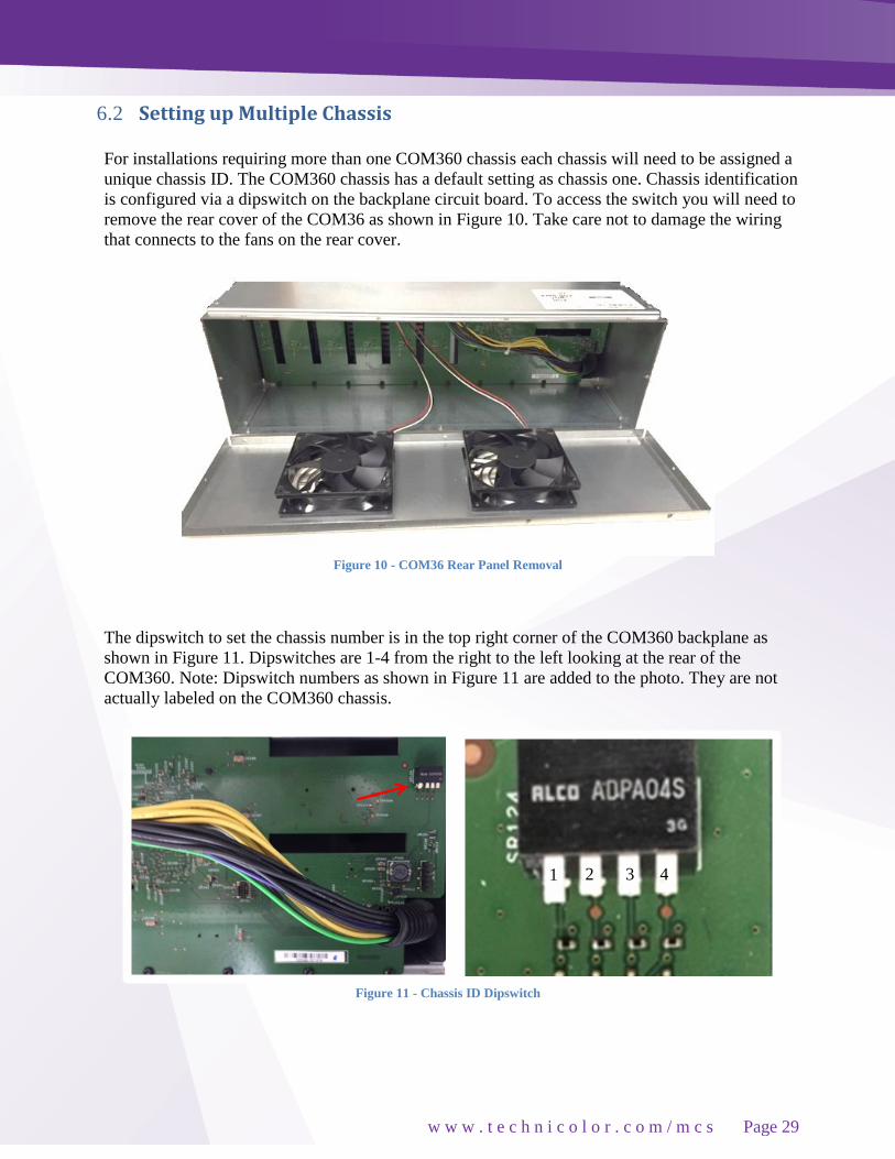
6.2 Setting up Multiple Chassis
For installations requiring more than one COM360 chassis each chassis will need to be assigned a
unique chassis ID. The COM360 chassis has a default setting as chassis one. Chassis identification
is configured via a dipswitch on the backplane circuit board. To access the switch you will need to
remove the rear cover of the COM36 as shown in Figure 10. Take care not to damage the wiring
that connects to the fans on the rear cover.
Figure 10 - COM36 Rear Panel Removal
The dipswitch to set the chassis number is in the top right corner of the COM360 backplane as
shown in Figure 11. Dipswitches are 1-4 from the right to the left looking at the rear of the
COM360. Note: Dipswitch numbers as shown in Figure 11 are added to the photo. They are not
actually labeled on the COM360 chassis.
Figure 11 - Chassis ID Dipswitch
2
2
1 3
2
2
4
2
2

w w w . t e c h n i c o l o r . c o m / m c s
Page 30
Set the chassis ID by changing the dipswitch settings as shown below in Figure 12.
The default IP address of each COM46 card in a system is determined by the chassis ID and slot
number the card is installed in.
The formula for determining this address is 192.168.3.[1 + (chassis ID X 16) + slot number].
Example for chassis one:
1 + (16*1) + 1 = 18 IP address of chassis one slot one is 192.168.3.18
Chassis ID Switch 1 Switch 2 Switch 3 Switch 4 Default IP Slot 1
1 UP DOWN DOWN DOWN 192.168.3.18
2 DOWN UP DOWN DOWN 192.168.3.34
3 UP UP DOWN DOWN 192.168.3.50
4 DOWN DOWN UP DOWN 192.168.3.66
5 UP DOWN UP DOWN 192.168.3.82
6 DOWN UP UP DOWN 192.168.3.98
7 UP UP UP DOWN 192.168.3.114
8 DOWN DOWN DOWN UP 192.168.3.130
9 UP DOWN DOWN UP 192.168.3.146
10 DOWN UP DOWN UP 192.168.3.162
11 UP UP DOWN UP 192.168.3.178
12 DOWN DOWN UP UP 192.168.3.194
13 UP DOWN UP UP 192.168.3.210
14 DOWN UP UP UP 192.168.33.36
Figure 12 - Dipswitch Settings for Multiple Chassis
w w w . t e c h n i c o l o r . c o m / m c s
Page 31
7 The COM2000 Web Interface
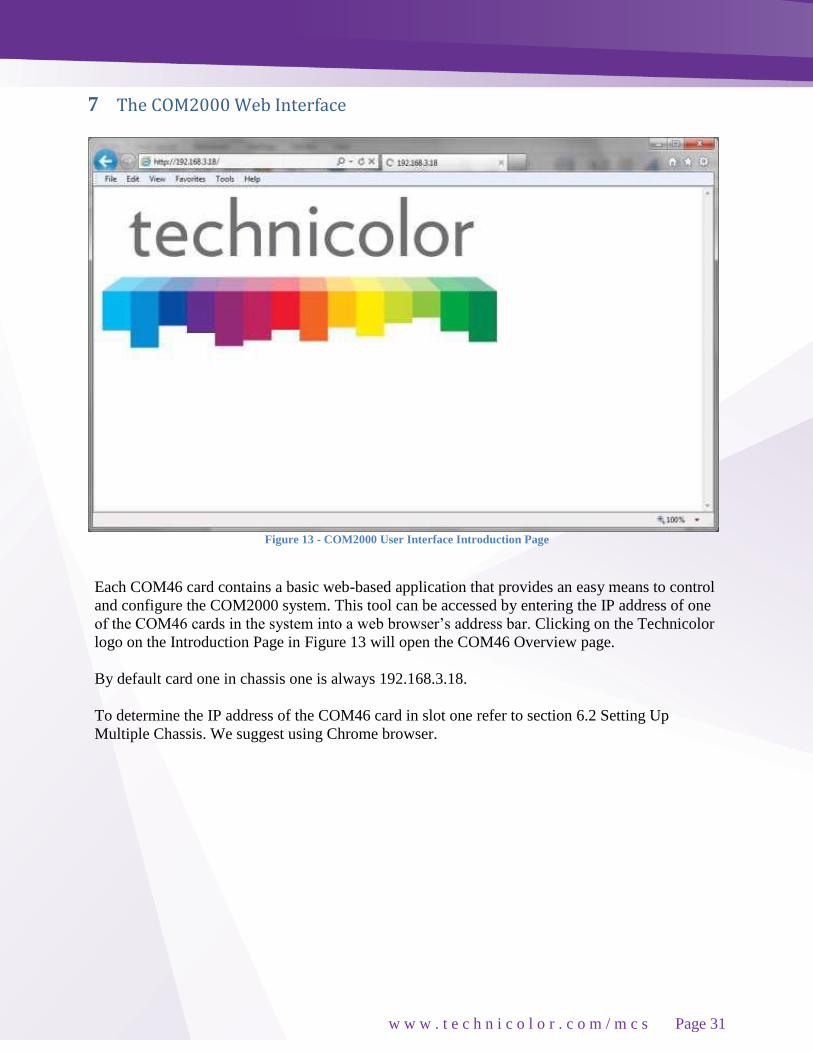
Figure 13 - COM2000 User Interface Introduction Page
Each COM46 card contains a basic web-based application that provides an easy means to control
and configure the COM2000 system. This tool can be accessed by entering the IP address of one
of the COM46 cards in the system into a web browser’s address bar. Clicking on the Technicolor
logo on the Introduction Page in Figure 13 will open the COM46 Overview page.
By default card one in chassis one is always 192.168.3.18.
To determine the IP address of the COM46 card in slot one refer to section 6.2 Setting Up
Multiple Chassis. We suggest using Chrome browser.
w w w . t e c h n i c o l o r . c o m / m c s
Page 32
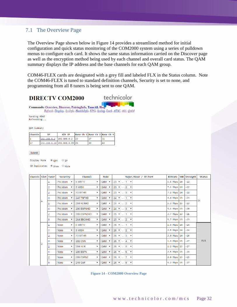
7.1 The Overview Page
The Overview Page shown below in Figure 14 provides a streamlined method for initial
configuration and quick status monitoring of the COM2000 system using a series of pulldown
menus to configure each card. It shows the same status information carried on the Discover page
as well as the encryption method being used by each channel and overall card status. The QAM
summary displays the IP address and the base channels for each QAM group.
COM46-FLEX cards are designated with a grey fill and labeled FLX in the Status column. Note
the COM46-FLEX is tuned to standard definition channels, Security is set to none, and
programming from all 8 tuners is being sent to one QAM.
Figure 14 - COM2000 Overview Page
FLX

w w w . t e c h n i c o l o r . c o m / m c s
Page 33
Hyperlinks - The IP hyperlink(s) in the QAM Summary below the Command tabs will take
you to the associated QAM tab. The hyperlinks in the Chassis, Slot, and Tuner columns allow
you to collapse the display for the selection so that multiple cards and chassis can be more
easily displayed.
Security - Figure 15 shows the Security column dropdown which allows you to apply any of
the supported security modes to the associated channel.
Options are:
None - This setting removes all DRM and will only function on CH100 or standard definition
channels. Removal of Pro:Idiom Encryption from HD channels must be authorized by
DIRECTV.
Pro:Idiom - This is the standard setting for HD, Pro:Idiom encrypted HD channels
Simulcrypt - For us with Samsung Link DRM server
Transcode - For use with Video Propulsion Floodgate MPEG2 Transcoder / QAM
Figure 15 – Encryption Settings

w w w . t e c h n i c o l o r . c o m / m c s
Page 34
Channel - Figure 16 shows the Channel dropdown feature. This allows you to assign a tuner
to any channel carried in the guide, including channels that the account is not authorized to
receive.
Figure 16 - Channel Drop Down Menu
Mode - Figure 17 shows the dropdown options for QAM and IP output modes.
Figure 17 - Output Mode
w w w . t e c h n i c o l o r . c o m / m c s
Page 35
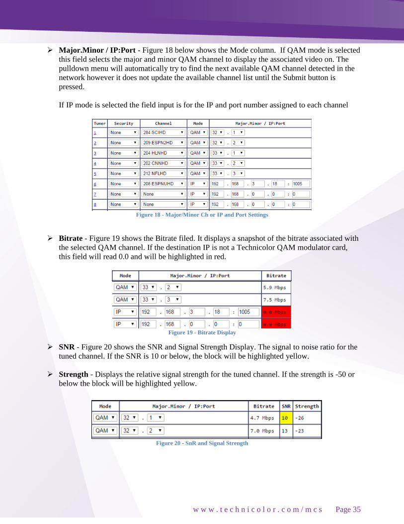
Major.Minor / IP:Port - Figure 18 below shows the Mode column. If QAM mode is selected
this field selects the major and minor QAM channel to display the associated video on. The
pulldown menu will automatically try to find the next available QAM channel detected in the
network however it does not update the available channel list until the Submit button is
pressed.
If IP mode is selected the field input is for the IP and port number assigned to each channel
Figure 18 - Major/Minor Ch or IP and Port Settings
Bitrate - Figure 19 shows the Bitrate filed. It displays a snapshot of the bitrate associated with
the selected QAM channel. If the destination IP is not a Technicolor QAM modulator card,
this field will read 0.0 and will be highlighted in red.
Figure 19 - Bitrate Display
SNR - Figure 20 shows the SNR and Signal Strength Display. The signal to noise ratio for the
tuned channel. If the SNR is 10 or below, the block will be highlighted yellow.
Strength - Displays the relative signal strength for the tuned channel. If the strength is -50 or
below the block will be highlighted yellow.
Figure 20 - SnR and Signal Strength

w w w . t e c h n i c o l o r . c o m / m c s
Page 36
7.2 Discover Page
Most configurations on the COM2000 system can be done via the Overview page previously
discussed. However, there are redundant controls in the Discover page in addition to controls for
advanced features and troubleshooting.
This section will detail all the controls available from the Discover page. The COM46 card issues
a discovery call for all other COM46 (and COM24) cards in the system, and then populates a table
with some basic information on current tuning parameters and RF signal levels. Once this
information is complete the Discover Web Page, showed in Figure 21 is displayed. This page
shows a basic data summary that is also similar to the pages you will get by clicking on the
Refresh, or Display hyperlinks at the top of any COM2000 web interface page.
Figure 21 - COM46 Discover Page

w w w . t e c h n i c o l o r . c o m / m c s
Page 37
7.3 Explanation of Discover Page Fields
Chassis - This field reports a unique identifier for the chassis. In systems that contain multiple
chassis, this can be used to identify each card in the system. See Section 4.1 on how to assign
unique identifiers to multiple chassis within a system.
Slot - This field identifies the card’s location within a chassis, numbered 1 through 6. If this
field is grey, the slot number is a link to messages in the CAM Log.
Tuner - There are eight entries per CardIP for this column. This represents the eight tuners
available on each COM46 card.
QAM or IP Address - If some of the programs are streaming to a QAM6, then “QAM” is
displayed as the column header. If all signals are routed out of the system, then “IP Address”
will display as the column header instead. If the card is sending video to a QAM6, this field
shows a snapshot of the output QAM channel and QAM sub-channel number. If a card is
streaming video to outside of the chassis, this field will contain the destination IP address. Both
unicast and multicast addresses are supported.
Bitrate or Port - If some of the programs are streaming to a QAM6, then “Bitrate” is displayed
as the column header. If all signals are routed out of the system, then “Port” will display as the
column header instead. If the card is sending video to a QAM6, this field shows the
instantaneous bitrate of the channels being sent out of the QAM6. Otherwise this field contains
the destination port associated with the destination IP address described above. You must have
a unique port number for each individual channel you wish to stream.
Channel - This field shows the Channel Name and the DIRECTV channel number you tune to
on a typical DIRECTV tuner. This field is also a link that permits the user to change channels.
If the smart card has not been authorized or paired then the channel will be highlighted in red.
SNR - This field returns the Signal-to-Noise Ratio associated with the selected tuners. If the
SNR is low, it will be highlighted in yellow and if the SNR is very low, it will be highlighted in
red. For optimum performance of the COM2000, this value should be 11 or higher.
Strength - This value provides a value corresponding to the internal Automatic Gain Control
setting in the COM46. If the Strength is low, it will be highlighted in yellow and if the Strength
is very low, it will be highlighted in red. For optimum performance of the COM2000, this value
should be somewhere between -25 and -55.

w w w . t e c h n i c o l o r . c o m / m c s
Page 38
7.4 The Tune Command
The Basic Tune screen shown in Figure 22 can be accessed by clicking the ChannelNumber link
in the Channel column of the Discover page (see Figure 21.) You can also access the Basic Tune
screen of any given COM46 card and tuner combination by clicking the channel name/number
hyperlink in the Channel column on the Refresh or Display pages.
Figure 22 - COM46 Basic Tune Screen
This page permits two different ways of tuning DIRECTV channels with Pro: Idiom encryption.
The first way specifies the destination IP address and port along with the DIRECTV channel
number. The second allows entry of a QAM channel, sub-channel and DIRECTV channel
number
Dest_IP_Address - In this field, you will enter the IP address of the device you wish to stream
video content to (i.e. an edge QAM).
Dest_Port_Number - This field represents the port of the IP address you wish to stream video
to. Depending upon the destination, this value may not be freely chosen.
Major_Number - This field is equivalent to the DIRECTV channel number you tune to on a
typical DIRECTV tuner. The second way is used if a QAM6 is in the chassis. The QAM major
and minor numbers are set along with the DIRECTV channel number. The IP address will be
set to 192.168.6.(chassisId+1) and the port will be set the QAM_Index * 16 +
QAM_subchannel.
QamMajor - The QAM6 output QAM major channel number. This corresponds to the channel
number from the North American Cable Television Frequency Plan (see EIA-542B or
http://www.jneuhaus.com/fccindex/cablech.html ).
w w w . t e c h n i c o l o r . c o m / m c s
Page 39
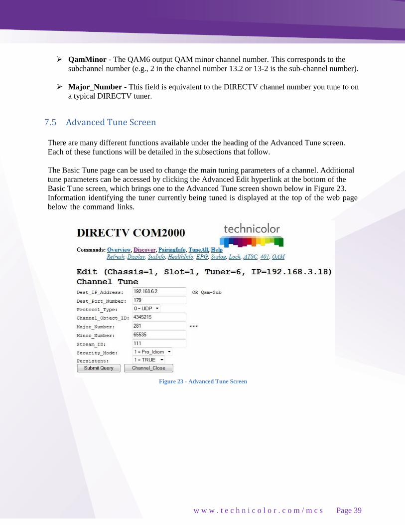
QamMinor - The QAM6 output QAM minor channel number. This corresponds to the
subchannel number (e.g., 2 in the channel number 13.2 or 13-2 is the sub-channel number).
Major_Number - This field is equivalent to the DIRECTV channel number you tune to on
a typical DIRECTV tuner.
7.5 Advanced Tune Screen
There are many different functions available under the heading of the Advanced Tune screen.
Each of these functions will be detailed in the subsections that follow.
The Basic Tune page can be used to change the main tuning parameters of a channel. Additional
tune parameters can be accessed by clicking the Advanced Edit hyperlink at the bottom of the
Basic Tune screen, which brings one to the Advanced Tune screen shown below in Figure 23.
Information identifying the tuner currently being tuned is displayed at the top of the web page
below the command links.
Figure 23 - Advanced Tune Screen

w w w . t e c h n i c o l o r . c o m / m c s
Page 40
A unique tuner can be identified by chassis number, slot number, tuner number, and IP
Address.
Chassis - This value shows the Chassis number of the COM360 that holds the COM46 card
you are currently tuning.
Slot - This value shows the Slot number within the COM360 chassis that holds the COM46
card you are currently tuning.
Tuner - This value indicates which tuner on the COM46 card you are controlling.
IP - This field shows the IP address of the COM46 card you are currently interacting with.
A detailed description of each advanced tuning field on the Advanced Edit page follows:
Dest_IP_Address - In this field, you will enter the IP address of the device you wish to stream
video content to (e.g. an edge QAM). The COM46 will stream to any valid unicast or
multicast address.
Dest_Port_Number - This field represents the port of the IP address you wish to stream video
to. Depending upon the destination, this value may not be freely chosen. The default value is
0.
Protocol_Type - This field is used to control whether the COM46 streams the data in UDP or
RTP packet structures. The default value is UDP.
Channel_Object_ID - This field is the data that the COM46 actually uses for tuning
purposes. It will be automatically filled in when a valid DIRECTV channel number is entered
into the “Major_Number” field. Before the card has been successfully tuned, the default value
is 0.
Major_Number - This field is equivalent to the DIRECTV channel number you tune to on a
typical DIRECTV tuner. The default value is 0.
Minor_Number - This field is automatically filled in by the COM46 card, with a default
value of 65535. If the DIRECTV channel has a minor channel number then the
Minor_Number value must be entered. Many DIRECTV channels have both high-definition
and standard-definition channels with the same Major and Minor numbers. The COM46 will
prefer the high-definition channels in this case. To prefer the standard-definition channels
instead, add 100000 to the Minor_Number. In most cases, this would cause the
Minor_Number to be 165535 if the standard-definition channel is desired. A COM46-FLX
which has not been upgraded to HD will only allow tuning to standard-definition channels.

w w w . t e c h n i c o l o r . c o m / m c s
Page 41
Stream_ID - This field is optional, and allows a unique identifier to be applied to every
video stream produced by the COM2000 system. The allowable values for this field are any
whole number between 1 and 65535. The default value is 111. To enable a second audio
stream set the Stream_ID to 54000.
Security_Mode - Typically, this field will not need to be changed. The only settings most
should be concerned with are:
o None - Setting will only work on DIRECTV channel 100. This allows you to turn
Pro: Idiom encryption off so that a standard HDTV or PC-based utility like VLC
Media Player can be used for troubleshooting.
o Pro_Idiom – This is the standard setting for HD Pro:Idiom encrypted channels.
o Simulcrypt - The Simulcrypt mode is used with the Samsung LYNK© system.
o Transcode – Transcode is to be used only with Video Propulsion Floodgate MPEG2
Edge QAM.
Persistent - Setting this value to ‘1’ tells the COM46 to retain all channel and IP-
destination settings in memory (i.e., data entered into the card is “persistent”). This
eliminates the need to reprogram the COM46 cards after every power-cycle or reboot.
Persistent is on by default (i.e., 1). It should be on for most installations. Otherwise, all
settings will be lost in the event of a power interruption.

w w w . t e c h n i c o l o r . c o m / m c s
Page 42
7.6 COM46 Informational Status
The information shown in Figure 24 below is one of the subsections available on the Advanced
Edit page.
Figure 24 - "Info" Section of the Advanced Edit Page
This section provides a selection of many key indicators to the operation of the COM46 card. It
acts as a concise index to the characteristics of each individual COM46 card according to its
status and user-defined settings.
Following is a brief explanation of each field shown above:
Chassis_ID - This field represents which COM360 chassis the card resides in when there are
multiple chassis in the system.
Slot_ID - This field identifies the card’s location within a chassis, numbered 1 through 6.
Tuner - This field identifies the tuner’s location on the COM46 card (1 through 8).
Card_IP - This field shows the IP address of the COM46 card you are currently interacting
with.
Receiver ID - This field reports the DIRECTV Receiver ID, or RID. This value is the first of
two parameters required to obtain authorization on the DIRECTV network.
CAM_ID - This field reports the DIRECTV CAM ID. This value is the second of the two
parameters required to obtain authorization on the DIRECTV network.
Network_ID - This field displays the DIRECTV network of the currently tuned channel. This
number correlates to a specific satellite, and can be used in conjunction with the Frequency
Index” field below to determine whether the card is locked to the correct channel.

w w w . t e c h n i c o l o r . c o m / m c s
Page 43
Frequency_Index - This field reports the frequency index corresponding to the channel the
tuner is currently set to. Frequency_Index is a 0 base value. Transponder #s on meters and IRD
are 1 base. To determine the channel’s transponder add 1 to the Frequency Index.
o The table below in Figure 25 details the Network_ID and corresponding satellite.
Network_ ID Satellite
0 101
2 110
3 119
10-11 99
14-15 103
Network ID = 10 Satellite 99
Frequency Index= 135 +1 Transponder 136
In the above example we are looking at CNN HD.
Authorized - This field provides feedback on whether the card has been authorized within
the DIRECTV network. The card needs to be paired and authorized in order to receive
DIRECTV programming. A value of ‘1’ means that the card has been successfully
authorized; ‘0’ means that it has not yet been authorized, or has lost its authorization.
Paired - This field provides feedback on whether the smart card has been successfully
paired with the COM46 card. The card needs to be paired and authorized in order to receive
DIRECTV programming. A value of ‘1’ means that the card has been successfully paired; ‘0’
means that it has not yet been paired, or has lost its pairing.
Blackout - This field can be used to determine whether DIRECTV has issued a blackout of
the content on a particular channel. This is a good thing to investigate if the video suddenly
stops playing on any channel, but it is particularly likely to happen with nationally televised
sporting events. A value of ‘0’ means that the channel should be functioning properly; ‘1’
means that the programming on the selected channel is not currently available to you.
TVs will display a blackout message on screen in the event of a blackout.
SW_Version - This field reports the software version that currently resides in the COM46
card. All cards that have a similar web interface to the one described in this document
will have a version number of at least ST03.02.21.
Figure 25 - Network ID and Frequency Index

w w w . t e c h n i c o l o r . c o m / m c s
Page 44
7.7 COM46 LED Control Feature
The information shown in Figure 26 below is one of the subsections available on the Advanced
Edit page.
Figure 26 - LED Control
This section gives you the ability to assume control of the PWR LED temporarily. This feature
can help you easily identify a specific card within a chassis if there is ever any doubt about
which card you are accessing. A brief explanation of each field shown above is as follows:
LED_State – This field allows you to control the PWR LED. This may be used as a simple
means to identify a particular card within a chassis at a remote location. The allowed values are:
0 = Off
1 = On
2 = Flashing
7.8 COM46 CAM Log Data
The information shown in Figure 27 below is one of the subsections available on the Advanced
Edit page.
Figure 27 - CAM Log Interface
This section gives you the ability to read the log files generated by any COM46 card’s Conditional
Access Module (CAM), also known as its smart card. The messages reported here match the ones
that may be seen on a normal set-top box, and can be used to determine whether the card has been
properly authorized and paired.

w w w . t e c h n i c o l o r . c o m / m c s
Page 45
Under normal circumstances, an authorized card will produce a very short CAM log file that
looks like the image shown in Figure 28 below.
If, however, there are issues with the card’s authorization, you will see messages that look more
like this:
0 0 0: CARD_INSERTED
1 9 727: 727 - Program Not Available in Your Area (Service Blacked
Out) [GMT=Thu May 12 00:00:00 2011]
2 0 0: Can't view [GMT=Thu May 12 00:00:00 2011]
3 0 0: Blackout [GMT=Thu May 12 00:00:00 2011]
4 9 727: 727 - Program Not Available in Your Area (Service Blacked
Out) [GMT=Thu May 12 00:00:00 2011]
5 0 0: Can't view [GMT=Thu May 12 00:00:00 2011]
6 0 0: Blackout [GMT=Thu May 12 00:00:00 2011]
7 9 727: 727 - Program Not Available in Your Area (Service Blacked
Out) [GMT=Thu May 12 00:00:00 2011]
The 3-digit values starting with a “7” are the DIRECTV support extension numbers associated
with the error condition.
Other things that you may see reported here include messages about access card not being active,
wrong or missing RID number, card not paired, and programming information for audio-only
channels. Many commercial TVs won’t play audio-only channels.
There are a few fields as described below:
Refresh - Refreshes this display.
Clear_CAM_Log - Clears all current entries in that card’s CAM log.
Figure 28 - Cam Log Report

w w w . t e c h n i c o l o r . c o m / m c s
Page 46
7.9 COM46 Software Reset
The information shown in Figure 29 below is one of the subsections available on the Advanced
Edit page.
Figure 29 - Reset Interface
This section allows you to initiate software reset on the card identified in the “CardIP” field. This
is sometimes helpful in situations where a card has become non-responsive. Activating this feature
is the equivalent to pushing the recessed reset button on the face of the COM46 card, and has a
similar effect as pressing the small reset button on a traditional set-top box.
7.10 COM46 File Transfer Utility
The information shown in Figure 30 below is one of the subsections available on the Advanced
Edit page.
Figure 30 - File Transfer Interface

w w w . t e c h n i c o l o r . c o m / m c s
Page 47
Similar in function to the upgrade section found on the PairingInfo page, this section provides you
with a method of transferring software updates and license files to or transferring log data from
individual COM46 cards. See Section 11 for more information on upgrading your COM46 cards.
Following is a brief explanation of each field shown above.
Usage - This field is used to tell the COM46 which type of transfer to execute. Only four values
are available for customer use (all others are for development purposes only):
1 = MT – This option allows you to upload the special MediaTune authorization and channel
guide files. See COM2000 Technical Support - Mediatune Installation Folder on the
Technicolor / MCS website for details.
2 = Software Upgrade – This option is used to update the COM46 software. In this case, the
file is downloaded to the COM46 card displayed in the browser’s URL field.
3 = Log – This option tells the COM46 to transfer its log file to the destination entered in the
“IP_Address” field (i.e., log file is uploaded to PC).
4=License – This option uploads the XML license file that enables advanced features on
the COM46 such as the HD upgrade for the COM46-FLX.
Options above 5 & 6 are not enabled for field use.
Server_IP_Address - This field tells the COM46 card where to retrieve the software update or
license file or where to send the log file, based upon the “Usage” setting above. The default
value for this field is 192.168.1.254.
Filename - This value entered in this field tells the COM46 which file to download (in the case
of software updates and license files), or what name you want to give the log file being
transferred from the card.
Mode - This field is used to tell the COM46 card which file-transfer protocol to use for the file
transfers. The supported modes are TFTP (option ‘0’) and FTP (option ‘1’), allowing you to
select the mode that best works with the software you use for the transfer. The default setting is
0. The card will automatically reset after completing an upgrade.

w w w . t e c h n i c o l o r . c o m / m c s
Page 48
7.11 COM46 User Configuration Options
The information shown in Figure 31 below is one of the subsections available on the Advanced
Edit page.
Figure 31 - User Config Interface
This section gives you the ability to customize select features of the COM46 cards to better suit
your application. The cards actually support a few more features than shown here, but the two
most useful features have been made available here. You have the ability to set the IP address the
card uses or to change the mechanism the card uses to obtain IP addresses. You can also control
and configure the sending of log data to a PC or other monitoring mechanism via the Ethernet.
Following is a brief explanation of each field shown above:
IP_Config - This field allows for one of 3 methods of IP address assignments to be chosen.
The default IP_Config setting is 0. Which sets the card one in chassis one to 192.168.3.18.
See Section 6.2 Setting up Multiple Chassis.
0 = Default - In this mode the IP address is assigned to the card based on the chassis ID and slot
the card is currently in. The formula for this address is 192.168.3.[1 + (chassis ID X 16) + slot
number]
Example: chassis ID = 1 slot = 1 Default IP address = 192.168.3.(1 + 16 + 1) = 192.168.3.18
Example: chassis ID = 1 slot = 6 Default IP address = 192.168.3.(1 + 16 + 6) = 192.168.3.23
Example: chassis ID = 2 slot = 1 Default IP address = 192.168.3.(1 + 32 + 1) = 192.168.3.34
Example: chassis ID = 2 slot = 6 Default IP address = 192.168.3.(1 + 32 + 6) = 192.168.3.39
In the default IP mode the Base_IP and the Gateway fields are ignored. The Subnet field is also
ignored but the Subnet mask is set to 255.255.0.0 and is applied.
1 = DHCP_Persistent - In this mode all IP address information Base_IP, Subnet and Gateway are
taken from the DHCP lease that the DHCP server issues to the card and is stored in non-volatile
memory.

w w w . t e c h n i c o l o r . c o m / m c s
Page 49
4 = Fixed - In this mode the user sets the Base_IP, Subnet and Gateway fields. All fields MUST
be set. A Gateway MUST be defined regardless of it being there or not for this mode. Once you
set the card IP you must reboot the card.
8 = No Change - This setting does not actually represent a separate mode, but rather acts as a way
to tell the COM46 card that you would like it to continue using whatever mode it is currently
using. For example, you could use this selection to tell a card that is already using Fixed mode that
you want it to start using a different IP address by selecting this option and entering a different
value into the “Base_IP” field.
Base_IP - In the Default mode this field will display the IP address of the card. In the
DHCP_Persistent mode this field will display the last address stored in non-volatile memory.
In the Fixed mode this field is where you would enter the IP address you wish to assign to that
card.
Subnet - This field allows you to give a subnet mask of your choosing to the COM46 card.
This field is only applied in the Fixed mode.
Gateway - This field allows you to set a default gateway of your choosing for the COM46
card. This field is only applied in the Fixed mode and must be set when using that mode.
Time-to-Live - Time to Live field in IP protocol header.
Log_IP - This field allows you to direct the COM46 card to send its log files to an external
destination automatically. This is very useful for monitoring the health of the system over an
extended period. After entering the IP address of the destination, the log files will start being
forwarded to this address after a short delay. You may then run a system-logging utility like
Kiwi on the destination computer to capture this information. Once the Log IP is set you must
reboot the card.
Log_Level - This field allows you to define the level of detail that will be captured in the
resulting log files. Due to the complexity of this setting, it is strongly advised that it be left
blank unless someone from support has asked to change the value.
UtilConfig - This field is for development purposes only, and should be left blank unless you
have been asked to modify the value by someone from technical support.

w w w . t e c h n i c o l o r . c o m / m c s
Page 50
7.12 COM46 “Direct Tune” Feature
The information shown in Figure 32 below is one of the subsections available on the Advanced
Edit page. This section gives you a method to force a tuner to a particular satellite and transponder
pair. This ability can especially useful when attempting to track and isolate RF problems with the
COM2000 system. The data required to perform this operation can be gathered from the basic
“Tune” interface shown in above.
A brief explanation of each field follows:
Figure 32 - Direct Tune Interface
Tuner_Index - This field allows you to direct an individual tuner to tune to a specific
network ID and Frequency_Index.
Network_ID - This field displays the DIRECTV network of the currently tuned channel.
This number correlates to a specific satellite, and can be used in conjunction with the
“Frequency_Index” field below to determine whether the card is locked to the correct
channel version.
Frequency_Index - This field displays the DIRECTV frequency index of the currently
tuned channel. This number correlates to a specific transponder, and can be used in
conjunction with the “Network_ID” field above to determine whether the card is locked to
the correct channel.
7.13 Remote Access Feature
Advanced feature set not yet released.
Figure 33 - Remote Access Feature

w w w . t e c h n i c o l o r . c o m / m c s
Page 51
7.14 Using the VidPlay Feature
The VidPlay feature will stream video files from a NAS portable hard drive similar to a Western
Digital My Cloud. Enter the IP:Port information and the name of the files to be played.
Figure 34 - Vid Play
7.15 Using the COM46 “Simulcrypt” Feature
The information shown in Figure 35 below describes how to enable the use of the COM46 with a
Simulcrypt compliant encryption system such as Samsung’s LYNK© DRM system.
Figure 35 - Simulcrypt
SimulcryptIP - This is the IP address of the Simulcrypt (LYNK© as of April 2014) server. In
LYNK enabled systems this IP address will point to the COM46 card that has been configured
as the key server for the system or to the external LYNK key server provided by the distributor.
Port - This is the IP port of the server that will be looking for requests from the COM46 for
exchanging encryption information.
ChassisBitmap - This bit field can be used to allow an external LYNK key server to send
EMMs to multiple chassis. A one would be set for each chassis address to be supplied with key
messages. E.g. if a system has two chassis, configured as chassis 1 and 3, the ‘ChassisBitmap’
field would be set to 0xa.

w w w . t e c h n i c o l o r . c o m / m c s
Page 52
7.16 Using the COM46 REST Feature
REST feature send SOAP messages to a remote server for status monitoring via a
Representational State Transfer (REST) protocol. This feature requires a remote server able to
“catch” and store the REST messages. Contact Technicolor for more information.
Figure 36 - REST
7.17 Displaying COM2000 Status
By clicking the Display hyperlink at the top of any COM2000 web interface page, you can see the
information last obtained from a Discover or Refresh with the signal status of all cards in the
system as shown in Figure 37 below.
When used in conjunction with the Refresh commands, it simply filters the table so that all
discovered COM46 cards are shown at the top of the table and removes any system status
messages that may appear when running the previously covered functions.
Figure 37 - COM2000 Display Page

w w w . t e c h n i c o l o r . c o m / m c s
Page 53
7.18 Pairing Info
By clicking the PairingInfo hyperlink at the top of any COM2000 web interface page, you
can quickly evaluate the authorization status of all cards in the system. In the example shown
in Figure 38, card 6 is activated but not paired with the CAM card. A follow up call to DIRECTV
activation will be required.
This page also provides direct access to a card’s internal syslog and CAM log and the ability to
upgrade multiple cards. These can be reached by clicking the hyperlinks that represent the card’s
IP address and CAM_ID, as can be seen below in Figure 38.
Figure 38 - COM2000 Pairing Info Page
Following is a detailed list of information available on the PairingInfo page.
Chassis - This field reports a unique identifier for the chassis. In systems that contain multiple
chassis, this can be used to identify each card in the system. See Section 4.1 on how to assign
unique identifiers to multiple chassis within a system.
Slot - This field identifies the card’s location within a chassis, numbered 1 through 6.
CardIP - This field shows the IP address of the COM46 card that resides in the chassis and
slot combination to its left. This field is also a link to see the Syslog for that card.

w w w . t e c h n i c o l o r . c o m / m c s
Page 54
RID - This field reports the DIRECTV Receiver ID, or RID. This value is the first of two
parameters required to obtain authorization on the DIRECTV network.
CAM_ID - This field reports the DIRECTV CAM ID. This value is the second parameter
required to obtain authorization on the DIRECTV network. You can click on the hyperlink in
this column to be taken directly to that card’s CAM Log (see Section 6.2.4 for more
information on reading a card’s CAM log).
Serial_Number – This field contains the unique electronic serial number of the board
assigned at the time of manufacture.
Authorized – This field reports whether the COM46 card’s CAM has been authorized. A
value of ‘1’ indicates that the card has been authorized, thereby enabling the card to receive
DIRECTV programming. A value of ‘0’ indicates that the card has not been authorized.
Paired – This field reports the pairing status of the CAM card. In order to be capable of
receiving an authorization to the DIRECTV network, the RID and CAM data must first be
paired. If this has not happened, then the card cannot be authorized until the pairing is
resolved. A value of ‘1’ indicates that the RID and CAM are successfully paired; a value of ‘0’
indicates that they are not.
SW_Version – This field reports the software version that currently resides on the COM46
card. All cards that have a similar web interface to the one described in this document will
have a version number of at least ST03.02.21.
Up_Time – This field gives an indication of how much time has elapsed since the card was
last rebooted or powered up.
Upgrade – By checking this box for a particular card, you will make each of the fields at the
bottom of the screen active for that card. This allows you to upgrade multiple cards at a time.
Figure 39 below shows in detail the upgrade section available on the PairingInfo page.
Figure 39 - COM46 Multi Card Upgrade

w w w . t e c h n i c o l o r . c o m / m c s
Page 55
Following is a brief description of the relevant fields on this page:
Usage - This field allows you to select which type of file transfer you wish to undertake for a
particular card. The available options are shown below. It should be noted that when selecting
any option other than ‘2’, the card will appear to go through the usual software update cycle,
but that it will revert to the current build of code once it has rebooted.
0 = Set_Log_IP – This option allows you to identify the IP address to which you wish to send
COM46 logging for monitoring by a syslog utility.
1= MT – This option allows upload of Mediatune channel files.
2= SW_Upgrade – This is one of two means of updating the software in a COM46 card.
3= Log – This option allows you to copy a COM46 card’s internal log files to a PC.
4= License – This option allows you to load various software licenses to enable new modes and
features in the COM46. One example might be upgrading the COM46-FLX to HD mode (only
with prior authorization from DIRECTV)
7 = KeyRenewal – This option will send a Pro:Idiom key renewal to any TV tuned to a RF
channel on the card selected.
Note: Options 5 AND 6 are not available to users and are for development purposes only.
Server_IP Address - This field gives the IP address of the server from which Filename: will
be uploaded. When doing a Mode 2 upgrade, this field can be the address of another COM46
card to which a SW update has already been uploaded. See the Browser Upload description
and Section 7 for details.
Filename - The name of the SW update binary or license file to upload.
Browser Upload - To eliminate the need for a 3rd party TFTP server, a COM46 can now act
as a TFTP server for other cards in the system but the file to be sent must first be uploaded to
the COM46 to be used.
The Browser Upload field allows you to upload the selected file to the card whose IP address
is shown below the Browser Upload heading from the web interface. The Choose File and
Upload buttons are used to find and upload the desired file(s) from the browser.

w w w . t e c h n i c o l o r . c o m / m c s
Page 56
7.19 Tune all Command
The information shown in Figure 40 below is the result of clicking the TuneAll hyperlink at the
top of the COM2000 web interface page.
Figure 40 - COM46 Tune All

w w w . t e c h n i c o l o r . c o m / m c s
Page 57
This section provides a practical way to configure an entire COM2000 system with minimal
effort. In order to use this feature, you can start by copying and pasting the information provided
at the bottom of the browser page (below the Submit Query button) either directly into the text
field provided or into your text editor of choice, and then modifying it as indicated by the guide
comments located above the text field. Examples are provided below to help you understand how
to utilize this feature.
Note: Saving a copy of the tuning table for your entire system in the form of a text file is
recommended, just in case the settings are not fully restored after a system reset.
The lines in the tuning table take the following form (see Section 1.1 for more on tuning):
Chassis-Slot-Tuner, IP_Address:Port_Number, Major_Number-Minor_Number-
Security_Mode;
The sample line below indicates the 1st tuner of a card residing in Slot #4 of Chassis #2. It is
targeting Port 301 of the device residing at the IP address 192.168.4.245, and tuned to the HD
broadcast of channel 242 with Pro:Idiom encryption set.
2-4-1, 192.168.4.245:301, 242-65535-1;
Upon initial system startup, your table might look something like this:
Current Tuning Table
1-1-1, 192.168.0.0:0, 0-0-0;
1-1-2, 192.168.0.0:0, 0-0-0;
1-1-3, 192.168.0.0:0, 0-0-0;
1-1-4, 192.168.0.0:0, 0-0-0;
1-1-5, 192.168.0.0:0, 0-0-0;
1-1-6, 192.168.0.0:0, 0-0-0;
1-1-7, 192.168.0.0:0, 0-0-0;
1-1-8, 192.168.0.0:0, 0-0-0;
After modifying the data to meet your system needs, it might look something like this:
Current Tuning Table
1-1-1, 192.168.4.245:6401, 3-65535-1;
1-1-2, 192.168.4.245:6402, 10-65535-1;
1-1-3, 192.168.4.245:6403, 29-65535-1;
1-1-4, 192.168.4.245:6657, 6-65535-1;
1-1-5, 192.168.4.245:6658, 17-65535-1;
1-1-6, 192.168.4.245:6659, 259-65535-1;
1-1-7, 192.168.4.245:6913, 209-65535-1;
1-1-8, 192.168.4.245:6914, 276-65535-1;
After editing the tuning table, you simply need to copy and paste this information into the large
field provided by the TuneAll command, and then click Submit Query.
If you are using a QAM6 Card, you can also use the syntax of Channel[hd|sd] -> QamMajor-
QamMinor

w w w . t e c h n i c o l o r . c o m / m c s
Page 58
For example, to tune the first unused tuner to the HD Science channel so that will it will be QAM
modulated at channel 50-1 use:
284hd -> 50-1
7.20 Refreshing the COM2000 Display
Figure 41 below is the result obtained by clicking the Refresh link at the top of any COM2000
web interface page. Please note that this table is filled in with data obtained during execution of
the Discover command. If some of the values appears to be wrong or empty after submitting an
entry, simply perform a Refresh to update this screen.
Figure 41 - COM2000 Refresh

w w w . t e c h n i c o l o r . c o m / m c s
Page 59
7.21 SysInfo
By clicking the SysInfo hyperlink at the top of any COM2000 web interface page, you will access
the page shown below. This table gives you the ability to identify a number of different unique
identifiers for every COM46 card as well as to identify which card in the chassis, if any, has been
assigned the generation of the Electronic Program Guide (EPG.)
Figure 42 - COM46 Sys Info Page
Following is a detailed list of the information available on the SysInfo (System Info) page.
Chassis - This field reports a unique identifier for the chassis. In systems that contain
multiple chassis, this can be used to identify each card in the system.
Slot – This field identifies the card’s location within a chassis, numbered 1 through 6.CardIP _
his field shows the IP address of the COM46 card that resides in the chassis and slot combination
to its left.
EPG
This field shows whether the card identified is generating EPG data.
MAC_Address
This value is loaded during the manufacturing process and is unique to every COM46 card. Every
IP-enabled device contains a similar address, which is used to ensure that all Ethernet traffic is
routed to the correct destinations.

w w w . t e c h n i c o l o r . c o m / m c s
Page 60
Features – This field displays the licensed operational features for each card.
HD
Card is licensed to deliver Pro:Idiom encrypted programming.
MT
Mediatune
IP
Licenses card for IP output in the absence of a QAM6.
Transcode
Authorizes card for use with Video Propulsion Floodgate MPEG2 Edge QAM. (Requires
DIRECTV authorization)
Clear HD
Allows HD programming to be output in clear QAM (requires DIRECTV authorization)
7.22 HealthInfo
By clicking the HealthInfo hyperlink at the top of any COM2000 web interface page, you will
access the page shown below in Figure 43. The data available here gives you an indication of the
overall health of the COM2000 system, and can be used to identify potential problem areas at a
glance.
Figure 43 - COM2000 Health Info Page
Following is a detailed list of the information available on the HealthInfo page.
Chassis – This field reports a unique identifier for the chassis. In systems that contain multiple
chassis, this can be used to identify each card in the system.
Slot – This field identifies the card’s location within a chassis, numbered 1 through 12.

w w w . t e c h n i c o l o r . c o m / m c s
Page 61
CardIP – This field shows the IP address of the COM46 card that resides in the chassis and slot
combination to its left.
Card_Temperature – Deprecated in the COM46.
IC_Temperature – This field reports the internal temperature of the main processor chip on the
COM46 card. An elevated temperature here and nowhere else could mean that this chip is
defective.
PS 0 & 1 Health – Deprecated. These fields will always report N/A in a COM46.
Fan0 Health – This field reports the health for Fan 0. If the fan is connected and operating
properly, the value should return “OK”. If there is a problem the value will return “Fault”.
Fan1 Health – This field reports the health for Fan 1. If the fan is connected and operating
properly, the value should return “OK”. If there is a problem the value will return “Fault”.

w w w . t e c h n i c o l o r . c o m / m c s
Page 62
7.23 Syslogs
Syslog Overview
The system log file for the COM 2000 system recorded Simple Object Access Protocol (SOAP)
messages related to the performance of the cards. Much of the data in the logs is not relevant to
the cards performance. To guide a system operator through the log entry interpretation
Technicolor has changed key log entry errors to red font.
The information shown below is the result of clicking the Syslog hyperlink at the top of any
COM2000 web interface page. Note that the syslog will only show the last 500 lines of messages
from the card you are currently logged into.
Figure 44 - Syslog Example
Figure 44 above shows a SWiM error occurred and cleared in less than two seconds.
In addition to clicking the Syslog hyperlink at the top of any COM2000 web interface page, the
syslog data may also be accessed directly from the PairingInfo screen as discussed in by clicking
directly on the hyperlinks for each card’s IP address. If you are experiencing problems with the
COM2000 system a quick check of the SYSLOG can alert you to problems. Contact your
distributor or Technicolor support for further assistance.
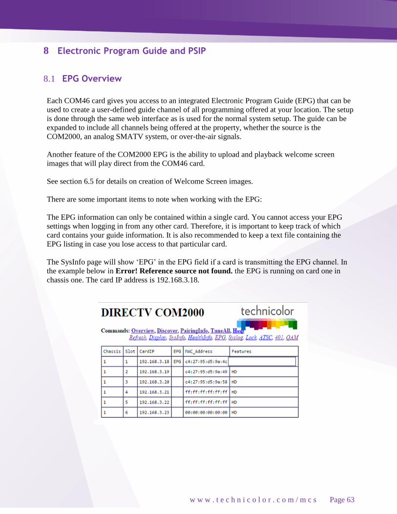
w w w . t e c h n i c o l o r . c o m / m c s
Page 63
8 Electronic Program Guide and PSIP
8.1 EPG Overview
Each COM46 card gives you access to an integrated Electronic Program Guide (EPG) that can be
used to create a user-defined guide channel of all programming offered at your location. The setup
is done through the same web interface as is used for the normal system setup. The guide can be
expanded to include all channels being offered at the property, whether the source is the
COM2000, an analog SMATV system, or over-the-air signals.
Another feature of the COM2000 EPG is the ability to upload and playback welcome screen
images that will play direct from the COM46 card.
See section 6.5 for details on creation of Welcome Screen images.
There are some important items to note when working with the EPG:
The EPG information can only be contained within a single card. You cannot access your EPG
settings when logging in from any other card. Therefore, it is important to keep track of which
card contains your guide information. It is also recommended to keep a text file containing the
EPG listing in case you lose access to that particular card.
The SysInfo page will show ‘EPG’ in the EPG field if a card is transmitting the EPG channel. In
the example below in Error! Reference source not found. the EPG is running on card one in
chassis one. The card IP address is 192.168.3.18.

w w w . t e c h n i c o l o r . c o m / m c s
Page 64
The EPG is created in such a way that it provides the viewer with what appears to be an auto-
scrolling channel listing. It is essentially a dynamic MPEG video stream made up of still images
of the current programming. It moves down the list of assigned channels every 2.5 seconds,
creating a constant cycle, showing nine channels at a time. As such, the guide is not interactive,
so the viewer must manually tune to their channel of choice.
If the number of channels in the EPG fits in one screen (nine or less) the channel listing will not
scroll. This permits the installer to have multiple cards generating a different EPG channel
listing nine channels each. This will create the user experience that channeling up or down will
page up or down nine channels in the guide.
The EPG can also convert the DIRECTV guide information into PSIP guide information that is
decodable by many televisions. PSIP permits the channel number to be remapped, the channel
name can be displayed, the current time displayed, and the current and next program titles
displayed.
To generate PSIP guide information, the last two numbers for each channel must list the
QAM6 chassis number and QAM6 destination port number. This information is automatically
filled in when EpgLoad is clicked. To disable PSIP guide generation for a channel, set the port
number to -1. If the DestIP is a valid IP address but the DestPort is 0, then the EPG channel is
disabled but PSIP guide generation is still enabled. This makes it possible to have one card
provide PSIP data and a separate card provide guide only.
Different TVs may interpret and display PSIP data differently. It is recommended to test PSIP
operations prior to installation.
It is possible to add non-DIRECTV channels to the EPG. This is done by adding an entry where
instead of a DIRECTV channel number, the capital letter ‘N’ appears followed by the channel
name, and program information separated by underscore characters.
For example:
10-1 NLobby_The_lobby_channel 1 17
Each channel in the EPG is comprised of a still image and it can take up to 10 seconds to
produce the image for every channel being offered when the EPG is first loaded. For
example, a location offering a list of 18 channels can expect to wait up to 3 minutes for a first-
time EPG configuration.
Due to the combination of the auto-scroll programming and the constant addition of new
channels, you can expect the EPG to exhibit some odd behavior during the initial image
creation. It may appear to skip around at random, but it can be expected to settle back into a
normal operational state once it has finished generating all the necessary images.
The EPG is a video-only channel, and you cannot set audio to play in the background.

w w w . t e c h n i c o l o r . c o m / m c s
Page 65
8.2 Getting Started with EPG
In order to access the EPG setup screen shown in Figure 45 below, simply click the EPG
hyperlink at the top of any COM2000 web interface page.
Figure 45 - COM2000 EPG Page
Following is a brief explanation of each field available on the EPG page as shown above:
DestIP
This field represents the IP address of the device you wish to send the EPG data to. In a typical
installation, this will be the address of the edge QAM device. The default value is 0.0.0.0.
Typically this will be the IP address of the QAM6 card you are going to use for the EPG channel.
In this example it is the second QAM on chassis 1, 1921.168.2.18
Note: the default value of 0.0.0.0 can be entered at any time to disable the EPG channel.
DestPort
This field represents the port number that is to be used to map the EPG to a specific QAM
channel. The default value is 0.
TimezoneOffset This field is used to tell the COM46 to shift the guide data by the appropriate amount of time to
account for the property’s time zone. Example values can be seen to the right of the field. The
default value is 0.
TimezonePsip
This field allows DCI401 boxes to align with TVs using PSIP. Most TVs have a time zone setting,
the DCI401 is based on GMT. Offset for GMT to synchronize a TV using a DCI 401 to a direct
tuning TV. The same values are used as in the Timezone Offset field.

w w w . t e c h n i c o l o r . c o m / m c s
Page 66
IgnoreDST
This field is used to tell the COM46 to ignore Daylight Savings Time, if needed. This is
accomplished by entering a value of ‘1’ here. The default value is 0. If you are setting up the
Home screen feature set this field to 2.
LogoTftpServerIP
This field is used to tell the COM46 where to find the custom logo for the property. This will be
the IP address of the PC containing the TFTP server.
LogoFileName
This field is used to tell the COM46 the name of the file that is to be used for the logo.
The EPG’s channel lineup is created in the large textbox on the lower half of the screen, using the
following format:
displayNumber majorNumber-[minorNumber]-[hd|sd] QAMchassis port
displayNumber
This is the TV channel that the viewer will find the program on. majorNumber – This is the same
as the “Major_Number” field in the Channel Tune interface.
minorNumber
This is the same as the “Minor_Number” field in the Channel Tune interface. Please note that on
submission, the EPG will default to ‘65535’ if this value is not provided.
hd|sd
This tells the guide whether to pull the data for the HD or the SD version of a particular channel.
The default behavior for the COM2000 is to look for HD channels, so this setting allows you to
add SD channels to the EPG if needed. Please note that on submission, the EPG will default to
‘hd’ if this value is not provided.

w w w . t e c h n i c o l o r . c o m / m c s
Page 67
QAMchassis
This tells the guide which chassis the QAM6 is in so that it knows the QAM6’s IP address for
sending PSIP guide data. If not using PSIP this field can be set to -1.
Port – This tells the guide which QAM6 UDP port is being used for sending PSIP guide data. If
not using PSIP this field can be set to -1.
Examples:
10 501-65535-hd ➔ TV channel 10 carries HBOHD (from COM2000)
23 209-65535-hd ➔ TV channel 23 carries ESPN2HD (from COM2000)
45 202-65535-sd ➔ TV channel 45 carries CNN (from SMATV or COM2000)
37 8-65535-hd ➔ TV channel 37 carries local channel 8 (from OTA, SMATV, or
COM2000)
2-1 NLocal_Program_Info 1 71 ➔ Non-DIRECTV channel (channel name Local)
Note: The actual content could come from the COM2000, a separate analog SMATV system, or
even from on-air, as long as the channel is available in DIRECTV’s lineup.

w w w . t e c h n i c o l o r . c o m / m c s
Page 68
The first time you access the EPG page, it will be blank. Note that, as mentioned previously, this
page applies to the card that you are currently logged in to, and that an EPG can only exist on one
card. If you have previously completed an EPG configuration and instead see a blank page like the
one shown above, you are probably logged in to the wrong COM46 card. After a successful
configuration, the screen should look similar to the one shown below in Figure 46.
Figure 46 - COM2000 EPG Page (Configured)

w w w . t e c h n i c o l o r . c o m / m c s
Page 69
8.3 Configuring the EPG
The screen shown in Figure 47 below is the result of clicking the EpgLoad button located at the
bottom of the EPG screen. Doing this provides a convenient starting point for building an EPG for
your system. To set a custom channel map change the RF channels listed to the preferred channel
ring.
Figure 47 - COM46 EPG Load Result
The results shown on this page contain the programming information for all COM46 cards in your
system based on the current tuning table. The function assigns channel information starting from
the first tuner on the leftmost card in the lowest-numbered chassis and steps up one channel for
every successive tuner. This information will automatically be loaded into the appropriate text
field the next time you visit the EPG page.
In order to customize the EPG to match the property’s lineup, you will need to go back to the
main EPG screen by clicking the EPG link at the top of the page. From this screen, you will need
to tell the COM46 card where to send the EPG data (a QAM6, for instance), define a time zone

w w w . t e c h n i c o l o r . c o m / m c s
Page 70
offset, and modify the lineup as needed. You may also upload a logo for the property that will be
displayed in the upper right corner of the EPG.
When modifying the EPG channel lineup, the channels can be entered in any order, as the COM46
card will automatically sort them by channel number when it builds the guide. As with the tuning
table on the TuneAll page, you may edit the EPG information in its text field on the page, but it is
recommended that you make all changes in a separate text editor and save a copy of the text file
for easy retrieval in the case of any information loss.
Example:
The first line of text is:
33-1 621-65535-sd 1 65
RF channel 33-1 is playing DIRECTV channel 621 on QAM6 #1 Port 65
Changing the channel designation will show the channel as mapped and will send PSIP
information to the TV.
2-0 621-65535 –sd-1-65
Now DIRECTV channel 621 will be distributed through the RF network on ch 33-1, but the EPG
data will display CH 621 information as playing on channel 2. PSIP will instruct the TV to look
for programming on 33-1 when CH 2 is selected.
Once you are finished entering all of the information necessary to build your EPG, simply click
the “Submit Query” button at the bottom of the screen. Doing so will provide you with a screen
that reports all of the data the COM46 card has been sent. This screen will look similar to the
resulting screen after clicking the EPGLoad button. Once the EPG has had enough time to
configure, the resulting guide channel should look like Figure 48 below.
Figure 48 - Guide Channel

w w w . t e c h n i c o l o r . c o m / m c s
Page 71
8.4 Logo upload
The COM46 has a built-in facility for superimposing a property’s logo into the upper right corner
of the EPG. Should the System Operator express an interest in providing such a logo, it is
entirely up to the property to employ someone to do so. It is recommended that you work with
someone in either the property’s Branding or Corporate Identity department or with a graphics
professional in order to obtain an image that is in the proper format to be added to the EPG.
In order to work properly with the EPG, the logo must be saved as a 24-bit bitmap (*.bmp) file,
and can be no larger than 170x60 pixels in size (170 pixels wide and 60 pixels long). In addition,
the image’s background can be made to render as transparent by changing the color to magenta
(RGB values of 251-0-255). An example of this can be found in Figure 49 below.
Once the image has been properly uploaded by using the “LogoTftpServerIP” and
“LogoFileName” fields on the EPG page, you should see the logo appear in the upper right corner
of the guide channel screen, as can be seen in Figure 50 below.
Figure 50 - Guide Channel with Custom Logo
Original Image Modified Image On-screen Appearance
Figure 49 - EPG Logo Creation

w w w . t e c h n i c o l o r . c o m / m c s
Page 72
9 Welcome Screen The welcome screen feature allows the creation and playback of up to 10 static images on a QAM
channel. Each channel will use the EPG function on a card not currently being used for EPG. The
images will change approximately every 15 seconds. EPG on each COM 46 card can send an
image to a different QAM port.
9.1 Image creation Welcome screens need to be formatted as 24 bit 720x480 bitmaps.
For the purpose of this exercise, we will use PowerPoint to create a screen and Paint to size the
file.
Save the PPT as “welcome1” (all lower case with no spaces) as a Device Independent Bitmap
(*.bmp), as shown in Figure 51 below.
Figure 51 - Welcome Screen Image Creation

w w w . t e c h n i c o l o r . c o m / m c s
Page 73
Next open the file in Microsoft Paint.
Use the Resize and Skew feature to set the image to 720X480 as shown in Figure 52. 1. Select Resize by Pixels
2. Set Horizontal to 720
3. Set Vertical to 480
4. Uncheck Maintain Aspect Ration
5. Click “OK”
Figure 52 - Using Microsoft Paint to size welcome screen
Uncheck Maintain aspect ratio
Resize and Skew
Select Resize by Pixels
Enter settings
Click
OK

w w w . t e c h n i c o l o r . c o m / m c s
Page 74
Image will resize to correct format as shown in Figure 53.
Figure 53 - Correctly Sized Welcome Screen Image
Save file!!!
Repeat the above procedure to create multiple screens, welcome2, welcome3, etc. Note file names
must be lower case with no spaces.
9.2 Uploading Welcome screens to COM 2000
Determine Card to use:
Card must be running 03.02.21 software.
Log into a card not currently running EPG. You can verify from the SysInfo Tab as shown in
Figure 54.
Figure 54 - Determine Card to use for Welcome Screen

w w w . t e c h n i c o l o r . c o m / m c s
Page 75
Figure 55 shows the Browser Upload function. Upload file to the card FTP from the Pairing Info
tab.
Figure 55 – Upload Welcome Screen Files to internal TFTP

w w w . t e c h n i c o l o r . c o m / m c s
Page 76
Select EPG tab
1. Enter the IP address and port# of the QAM you want to use to stream the welcome screen.
2. Enter 2 in the ignore DST field.
3. Enter the IP address of card you are using for FTP
4. Enter the file name you uploaded.
5. Click Submit.
6. Reboot the COM46. When the reboot is complete the card’s EPG page will look similar to
Figure 56.
Figure 56 - Upload Welcome Screen Image to EPG
192.168.3.20
Welcome1.bmp
196

w w w . t e c h n i c o l o r . c o m / m c s
Page 77
If you are using PSIP or would like the welcome screen displayed in the EPG log into the card
running EPG and add the channel to the EPG information as shown in Figure 57.
Figure 57 - Adding Welcome Screen to EPG and PSIP

w w w . t e c h n i c o l o r . c o m / m c s
Page 78
You can verify the screens are streaming by checking for data on the corresponding QAM port as
shown in Figure 58 below.
Figure 58 - Verify Welcome screen is streaming
Your Welcome screen should now be playing on the TV. Screens scroll every 15 seconds.
To disable the Welcome screens set the DST field to 0.
Click Submit.
Reboot card.

w w w . t e c h n i c o l o r . c o m / m c s
Page 79
10 QAM6
10.1 QAM6 Overview
The QAM6 card is an Edge QAM that is installed directly into a COM360 chassis. It
connects to the COM46 cards via a GigE connection on the back edge of the card.
The board provides 12 QAM modulators in addition to the front 1 0 0 m b p s Ethernet port,
which can be used to manage the COM2000 system.
Each QAM channel can carry up to 3 HD or 8 SD video channels. When shipped from the
factory the QAM6 boards will only permit six QAM carriers to be active at a time. To
increase the number of QAM carriers, additional SWQAM2 licenses must be purchased from
your distributor and downloaded to the QAM6. Each license enables 2 more QAM carriers
per board up to a total of 12 carriers.
A COM360 chassis fully populated with COM46 receivers (48 channels total) requires 16 QAM
channels (3 HD channels per QAM). This requires 2 QAM6 modulators (12 QAMS) plus 2
additional SWQAM2 upgrade licenses. Additional SWQAM2 upgrades can be purchased for a
maximum of 24 QAM channels. These can be utilized for additional services such as ATSC-8, or
externally sourced video streams.
A front view of the QAM6 can be seen in Figure 59 below in figure.
Figure 59- QAM6
RF Output Card Edge Connector
Ethernet Port
LEDs

w w w . t e c h n i c o l o r . c o m / m c s
Page 80
10.2 QAM6 Settings and Configuration
The QAM6 card is controlled by any of the COM46 cards via Ethernet. The QAM6 card has a
fixed IP address = 192.168.6.“Chassis ID” + 1. An arbitrary alternate address can be assigned.
QAM output channels have a destination port of QAM Channel *16 + subchannel number.
The screen in Figure 60 shows the status of each channel. The RF groups are labeled Qam1-
Qam12.
Each RF channel can have up to 8 subchannels or programs. If a subchannel is active, its bit rate
will be shown. Bitrates are static snapshots.
The lower portion of the screen controls the RF output configuration and provides SW upgrade
capability.
12 RF output channels are defined in 3 groups of 4.
Each group of 4 is in a fixed channel sequence starting with the base channel. Each group’s base
channel can be set according to the North American Cable Television Frequency plan.
Each RF channel can be individually turned on or off.
Each channel must be frequency adjacent and within the same band per the North American Cable
Television Frequency Plan.
See
EIA standard EIA-542B
or
http://www.jneuhaus.com/fccindex/cablech.html
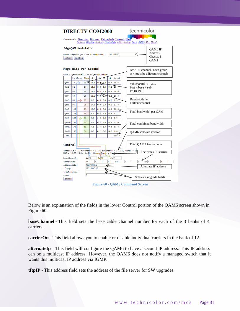
w w w . t e c h n i c o l o r . c o m / m c s
Page 81
Figure 60 - QAM6 Command Screen
Below is an explanation of the fields in the lower Control portion of the QAM6 screen shown in
Figure 60:
baseChannel - This field sets the base cable channel number for each of the 3 banks of 4
carriers.
carrierOn - This field allows you to enable or disable individual carriers in the bank of 12.
alternateIp - This field will configure the QAM6 to have a second IP address. This IP address
can be a multicast IP address. However, the QAM6 does not notify a managed switch that it
wants this multicast IP address via IGMP.
tftpIP - This address field sets the address of the file server for SW upgrades.
Base RF channel- Each group
of 4 must be adjacent channels
Sub channel -1, -2…
Port = base + sub
17,18,19…
Bandwidth per
port/subchannel
Total bandwidth per QAM
Total combined bandwidth
Total QAM License count
QAM6 software version
1 activates RF carrier
QAM6 IP
Address: Chassis 1
QAM1
Alternate IP address
Software upgrade fields

w w w . t e c h n i c o l o r . c o m / m c s
Page 82
tftpFilename - This field sets the filename of the new SW image.
Reset - This field executes a SW reset of the QAM6. It is almost user transparent but will create a
brief video glitch on the channels it is modulating.
Application Notes:
The QAM6 supports an emergency broadcast override. If a video stream is sent to port 25600
it will override all of the channels.
Some QAM6 boards have an RF spur that can interfere with analog television channels. The
spur is 1176 MHz minus the desired center RF frequency for each group of four channels. For
channels 23 through 94 this means that the spur will be at (1086 – 6 * channel) MHz Change
the frequency plan to minimize the impact of the RF spurs.

w w w . t e c h n i c o l o r . c o m / m c s
Page 83
10.3 QAM LOG
When troubleshooting QAM6 issues, click on the QAM Log button to see the QAM6 system log.
This log is mainly for Technicolor technical analysis but a short summary is:
A = Arp reply
bad(#) = Discarded # number of unexpected Ethernet packets.
C = Command and control message received
c## = Continuity counter error. May indicate multiple channels to same port. PMT## = PMT
changed on a channel
T = PCR discontinuity
An example of a normal QAM log is shown below in Figure 61.
Figure 61 - QAM Log Example

w w w . t e c h n i c o l o r . c o m / m c s
Page 84
11 Software Upgrade Procedures
When you first receive your COM2000 system, your distributor should have already installed the
most recent software on every COM46 card and QAM6. However, since we work to
continuously improve the software associated with the system, you may find it useful to stay
up-to-date as future versions are released. Please check www.technicolor.com/mcs for the latest
software for your system.
Note: The latest software releases covered in this manual are:
COM46 - ST03.02.21
QAM6 – QAM24_01.11.09
The following sections will explain in detail the upgrade options that were touched upon earlier
within the file transfer utility located under the Tune command and on the PairingInfo page.
11.1 Preparing for a Software Upgrade
Technicolor will at times releases new versions of software for the COM46 and QAM6 products.
Notifications are sent to product distributors with release notes. New software may address
performance enhancements and provide new features. It is recommended that the first step in any
troubleshooting process is to update the components to the latest software version. Contact your
distributor or Technicolor Support for the latest software version. Upon receipt save the file in a
known location on a computer to be used for service purposes. In most cases the software will
need to reside on a local machine networked to the COM2000. If you have a VPN route to the
system a remote computer should work to transfer the software to the COM46 TFP.
There are several different mechanisms available for upgrading the software in the COM2000.
Before proceeding any further, it is recommended that you first visit Section 5.2.1 on setting up
your network connections. If you are planning to use an external TFTP or FTP server review
Sections 5.1.5 and 5.3 on using FTP/TFTP and configuring your server in order to ensure that
everything is properly configured to perform this operation. Otherwise, one of the COM46s in the
system can be configured as a TFTP server.
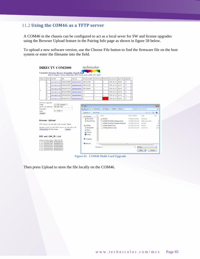
w w w . t e c h n i c o l o r . c o m / m c s
Page 85
11.2 Using the COM46 as a TFTP server
A COM46 in the chassis can be configured to act as a local sever for SW and license upgrades
using the Browser Upload feature in the Pairing Info page as shown in figure 58 below.
To upload a new software version, use the Choose File button to find the firmware file on the host
system or enter the filename into the field.
Figure 62 - COM46 Multi Card Upgrade
Then press Upload to store the file locally on the COM46.

w w w . t e c h n i c o l o r . c o m / m c s
Page 86
If the upload is successful, the filename will appear under the line “TFTP server at
xxx.xxx.xxx.xxx current files:” As shown in figure 59 below.
Once the selected file has been uploaded, the rest of the update procedure is the same as with the
COM24/COM1000 as described in Section 10.
Figure 63 - COM46 Software Upload
11.3 Performing Software Upgrades
DO NOT turn off power or unplug a card that is updating its SW image. Your card may
become unrecoverable
This section will guide you through the procedure for upgrading your COM46 cards. There are
two different ways you can go about doing this. The first method is a single-card upgrade, which
requires the use of the file transfer utility located on the Advanced Edit page (see Section 6.2.6).
The second and preferred method is a multi-card upgrade, the controls for which are located at the
bottom of the PairingInfo page.
Use the following settings for both methods:
The “Usage” option should be on ‘2 = SW_Upgrade.
The ‘Server_IP_Address’ will be the device that contains the upgrade file (your PC, file server, or
COM46 card).
The “Filename” will be the name of the upgrade file (e.g. COM46_ST03.02.21.bin”). It is
recommended that you retain the original filename of the update file you have been issued to
avoid confusion later on.
The mode determines whether the card tries to contact a FTP or TFTP server.
Software file uploaded
to COM 46 card
IP address of FTP card

w w w . t e c h n i c o l o r . c o m / m c s
Page 87
To use the single card upgrade method, go to the File Transfer section of the Advanced Tune
page. See Figure 64 below.
Enter the IP address of the server and filename of the new image as indicated above and press the
Submit button.
The same method can be used to enter a license file on a single card for an SD to HD upgrade or
other feature upgrade (see Section 7.4) only the Usage field should be set to ‘4 = License’.
Upgrading a COM46-FLX to a COM46 requires DIRECTV authorization.
Figure 64 - Advanced Edit File Transfer

w w w . t e c h n i c o l o r . c o m / m c s
Page 88
If one desires to update all of the COM46 cards in a chassis (multi-card upgrade method), then all
upgrade fields would be checked as shown in Figure 61 below.
Figure 65 - Multi Card COM46 SW Update
The results of the upgrade in Figure 61 are shown below in Figure 62.
Figure 66 - Multi Card Upgrade Results
Once the software has loaded the card will reboot. Click on the Discover tab and then the Pairing
info tab. The new software version number will be displayed in SW_Version column of the
Pairing info table.
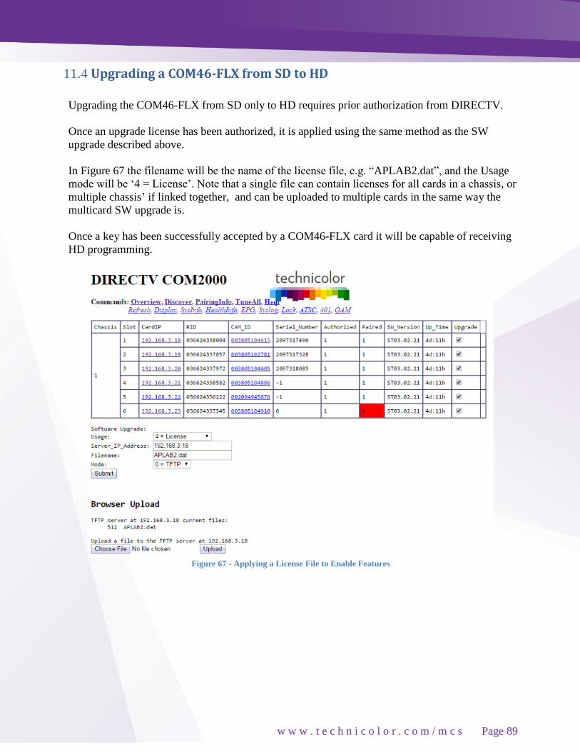
w w w . t e c h n i c o l o r . c o m / m c s
Page 89
11.4 Upgrading a COM46-FLX from SD to HD
Upgrading the COM46-FLX from SD only to HD requires prior authorization from DIRECTV.
Once an upgrade license has been authorized, it is applied using the same method as the SW
upgrade described above.
In Figure 67 the filename will be the name of the license file, e.g. “APLAB2.dat”, and the Usage
mode will be ‘4 = License’. Note that a single file can contain licenses for all cards in a chassis, or
multiple chassis’ if linked together, and can be uploaded to multiple cards in the same way the
multicard SW upgrade is.
Once a key has been successfully accepted by a COM46-FLX card it will be capable of receiving
HD programming.
Figure 67 - Applying a License File to Enable Features

w w w . t e c h n i c o l o r . c o m / m c s
Page 90
11.5 Upgrading QAM6 Software
Upgrading the software for the QAM6 is similar to updating the firmware for the COM46 and
except for the following differences:
QAM6 upgrade is TFTP only. Ftp is not available.
Only one QAM6 can be updated at a time.
QAM6 does not automatically reset after the new software is downloaded. It must be
manually reset by powering down the chassis or removing the QAM6 from the chassis.
To perform the QAM6 software update upload the software file to a COM46 TFTP as shown in
section 11.2.
Figure 68 - Upload QAM6 Software
Copy the file name then access the QAM command as shown below in figure 61.
Paste the file name into the tftpFilename field as shown in Figure 69. It is recommended that you
retain the original filename of the update file you have been issued to avoid confusion later on.
The “tftpIP” will be the IP address of the COM46 card used to upload the file.
Figure 69 - QAM6 Software Upgrade
copy
Paste file name
IP address of COM 46
card
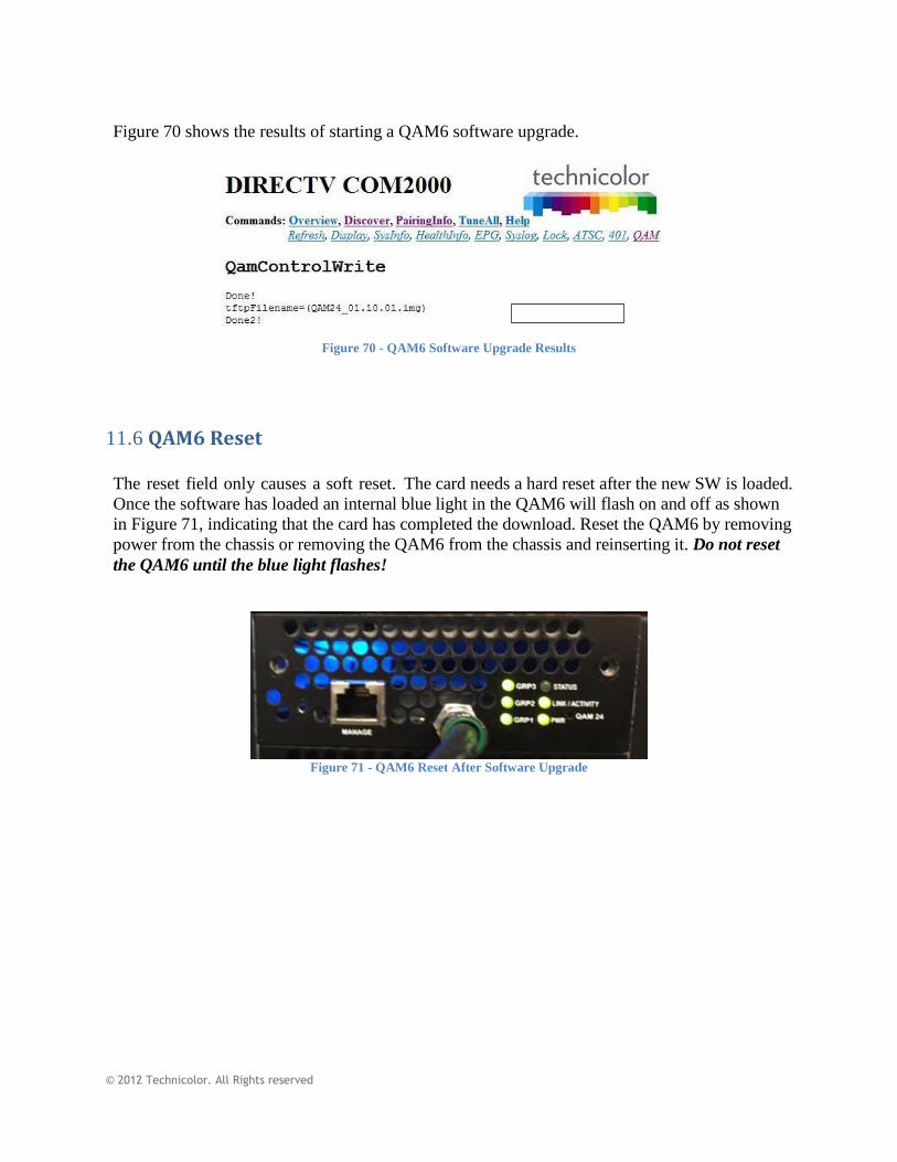
© 2012 Technicolor. All Rights reserved
Figure 70 shows the results of starting a QAM6 software upgrade.
Figure 70 - QAM6 Software Upgrade Results
11.6 QAM6 Reset
The reset field only causes a soft reset. The card needs a hard reset after the new SW is loaded.
Once the software has loaded an internal blue light in the QAM6 will flash on and off as shown
in Figure 71, indicating that the card has completed the download. Reset the QAM6 by removing
power from the chassis or removing the QAM6 from the chassis and reinserting it. Do not reset
the QAM6 until the blue light flashes!
Figure 71 - QAM6 Reset After Software Upgrade

w w w . t e c h n i c o l o r . c o m / m c s
Page 92
12 Modulation of External Video Sources
12.1 Overview The COM2000 system is capable of modulating any MPEG2 variable bit rate (VBR) media
source from an IP stream.
Each source must be assigned to an open QAM6 IP and port number.
QAM6 cards must be licensed for the appropriate number of QAM outputs to facilitate FTG
channels plus additional video sources. Media will be distributed on the RF channel assigned to
that port.
Care must be used not to exceed the 38.8 Mbps capacity of the QAM. You target bitrate should
be less than 30Mbps to allow headroom for bandwidth peaks in the VBR transport stream.
All networking gear needs to pass gigabit Ethernet (GiGE) bandwidth.
12.2 Source Options There are many options for video sources. Keep in mind that some video sources may require
special licensing to be displayed in a public place. Consult with you companies legal counsel
before modulating any commercially available content such as CDs, DVDs, or any programming
recorded from commercially distributed sources.
Some options for video sources include:
Network Attached Storage (NAS) drives – NAS drives similar to the Western Digital My
Cloud drive will store MPEG2 VBR media with the capability of assigning an IP destination
IP.
Video Servers – Video Servers such as the ZyCast HDIP-930 will convert media from HDMI
or Component Video sources to an IP stream which can be directed to the COM2000 QAM6
card.
PC Based Media – Video programs similar to VLC can route video streams to an IP
destination. This can be very useful for locally generated marketing media that needs to be
changed on a regular basis. Media files can be created on a USB drive and loaded on a local
machine.
Emergency Alert Systems – Emergency Alert Systems (EAS) can be pointed to the QAM IP
and port. Any stream sent to port 25600 will be duplicated on all QAM RF outputs. When
the data on port 25600 stops the QAM will broadcast the original content intended for each
port.
Note: Contact Technicolor support for EAS on systems with multiple QAM6 cards.

w w w . t e c h n i c o l o r . c o m / m c s
Page 93
13 Diagnostics
When it comes to troubleshooting your COM2000 system, the COM46 card has a few built-in
mechanisms that can assist you. Each of these can be very helpful in diagnosing general issues
associated with system status and card connections that will be covered in the following sections.
13.1 Indicator Lights
The nine indicator lights the COM46 & COM46-FLX faceplate have multiple functionalities. In
addition to providing a manual toggling ability of the Tuner 9 LED by utilizing the LED
controls on the Tune page the lights also exhibit a set of predefined behaviors for several
conditions.
In recognizing the behaviors associated with the three indicator lights, you must first familiarize
yourself with the three possible LED states. Figure 68 below names and describes them, and
provides a color by which the states will be defined in the following sections.
Figure 72 - LED States
13.2 Power Supply Issues
Unless a COM46 card has intentionally been removed from the COM360 chassis, the “PWR”
light on every card in the system should be lit. If none of the COM46 LEDs on a chassis are lit,
the power supply has likely been disrupted.
Check for the following:
The AC cords on each module are completely attached and plugged in.
Both modules are locked in place.
The power supply fans are running.
On The LED emits a steady green light.
Off The LED is not lit at all.
Flash The LED exhibits an on-off pattern once a second.

w w w . t e c h n i c o l o r . c o m / m c s
Page 94
If the above conditions have all been met and you still do not see any LEDs lit, there is probably
an issue with your system.
More commonly, you may see unlit LEDs on one or multiple COM46 cards, but not the
whole chassis. Things to check for when this situation occurs:
All COM46 cards are fully aligned in their grooves.
All COM46 cards are properly connected to their receivers on the back panel.
All thumbscrews are tightened completely.
If any COM46 cards remain unlit after ensuring that all of these conditions have been met,
there may be something wrong with the cards.
13.3 System Startup
It is important to understand the behaviors associated with the execution of normal procedures
before you can effectively diagnose any card issues. This section covers the sequence of events
that occur in a COM2000 system at boot-up.
The COM46 card goes through four steps at startup:
1) Self test This includes SWiM channel lock.
2) IP Initialization (obtain IP address, establish network connectivity)
3) DIRECTV Program Guide acquisition
4) Channel acquisition and video streaming
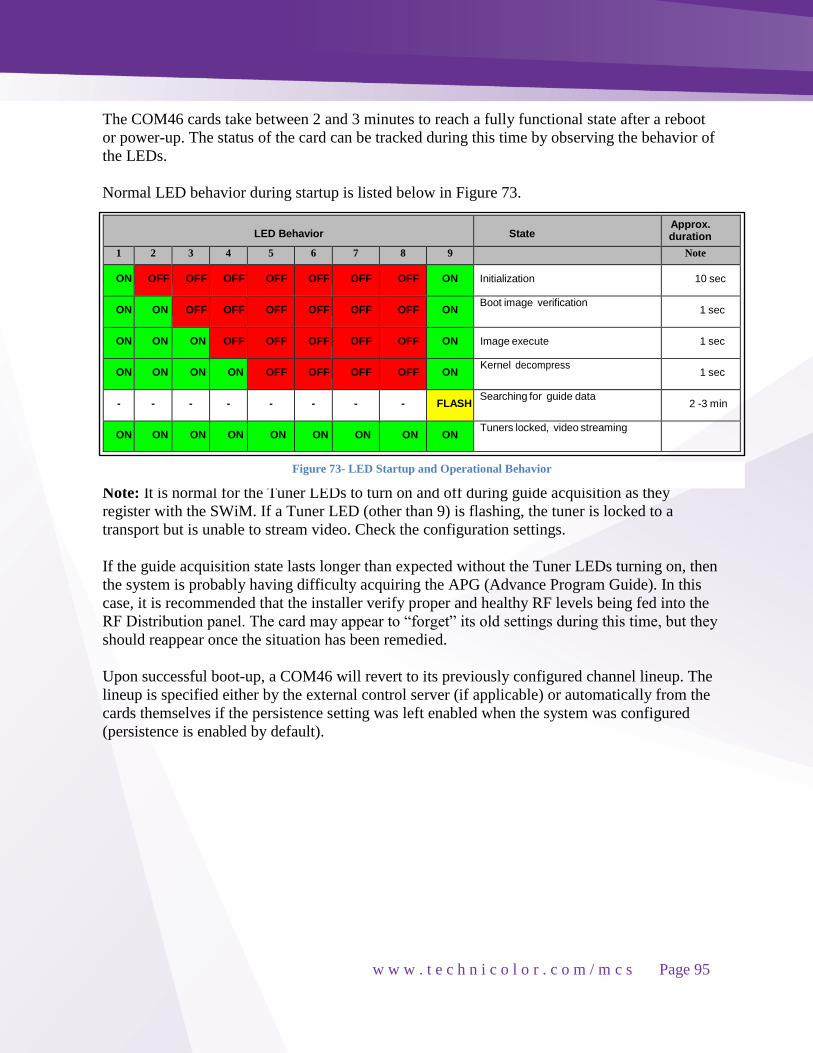
w w w . t e c h n i c o l o r . c o m / m c s
Page 95
The COM46 cards take between 2 and 3 minutes to reach a fully functional state after a reboot
or power-up. The status of the card can be tracked during this time by observing the behavior of
the LEDs.
Normal LED behavior during startup is listed below in Figure 73.
LED Behavior State Approx. duration
1 2 3 4 5 6 7 8 9 Note
ON OFF OFF OFF OFF OFF OFF OFF ON Initialization 10 sec
ON ON OFF OFF OFF OFF OFF OFF ON Boot image verification
1 sec
ON ON ON OFF OFF OFF OFF OFF ON Image execute 1 sec
ON ON ON ON OFF OFF OFF OFF ON Kernel decompress
1 sec
- - - - - - - - FLASH Searching for guide data
2 -3 min
ON ON ON ON ON ON ON ON ON Tuners locked, video streaming
Note: It is normal for the Tuner LEDs to turn on and off during guide acquisition as they Note:
Note: It is normal for the Tuner LEDs to turn on and off during guide acquisition as they
register with the SWiM. If a Tuner LED (other than 9) is flashing, the tuner is locked to a
transport but is unable to stream video. Check the configuration settings.
If the guide acquisition state lasts longer than expected without the Tuner LEDs turning on, then
the system is probably having difficulty acquiring the APG (Advance Program Guide). In this
case, it is recommended that the installer verify proper and healthy RF levels being fed into the
RF Distribution panel. The card may appear to “forget” its old settings during this time, but they
should reappear once the situation has been remedied.
Upon successful boot-up, a COM46 will revert to its previously configured channel lineup. The
lineup is specified either by the external control server (if applicable) or automatically from the
cards themselves if the persistence setting was left enabled when the system was configured
(persistence is enabled by default).
Figure 73- LED Startup and Operational Behavior

w w w . t e c h n i c o l o r . c o m / m c s
Page 96
13.4 Normal Operation
When operating under normal circumstances, there are a few characteristics you can expect to
see in LED behavior.
The PWR LED should always be lit. If the PWR LED is not lit and the chassis is powered,
check the COM46 for proper installation in the chassis.
During rainstorms or other conditions that may obstruct satellite communications, the receiver
may lose contact and be unable to receive guide data. At this point, the 9th (guide) tuner LED
will start flashing, and the other tuner LEDs may go dark.
A Tuner LED can exhibit one of three behaviors.
1) A tuner which is locked on to a signal and streaming video to a valid IP destination will
be in the ON state. The COM46 cards will maintain a lock on the signal at all times if
the signal strength and quality is within specifications (-25 to - 55 dBm per transponder)
and the connection between the COM46 and the SWiM module is working correctly.
2) An intermittently flashing Tuner LED indicates that the tuner is either having problems
locking to a satellite or it cannot stream video. Failure to lock to a signal usually
indicates a fault in the RF plant upstream or a problem in the communications link
between the SWiM and the COM46. Failure to stream video is likely to occur when you
are trying to tune to a channel that DIRECTV provides and you are capable of receiving,
but you have not purchased the content streaming on that channel.
3) A tuner whose LED is off is not locked onto anything. This most likely indicates that the
tuner is not set to stream anything. It could also mean that the card could not find the
channel specified, in which case you should check for the following:
The channel is one that DIRECTV actually provides.
You have entered the channel number correctly.
You are authorized to receive the channel.
If, after having reviewed the above checklist, the tuner LEDs are not lit when they are expected
to be, or if the 9th tuner LED begins flashing at a regular rate it is an indication that the card has
detected a problem. The remaining lit LEDs will display the code associated with the problem.
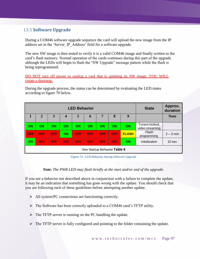
w w w . t e c h n i c o l o r . c o m / m c s
Page 97
13.5 Software Upgrade
During a COM46 software upgrade sequence the card will upload the new image from the IP
address set in the ‘Server_IP_Address’ field for a software upgrade.
The new SW image is then tested to verify it is a valid COM46 image and finally written to the
card’s flash memory. Normal operation of the cards continues during this part of the upgrade
although the LEDs will begin to flash the “SW Upgrade” message pattern while the flash is
being reprogrammed.
DO NOT turn off power or unplug a card that is updating its SW image. YOU WILL
create a doorstop.
During the upgrade process, the status can be determined by evaluating the LED states
according to figure 70 below.
LED Behavior State Approx. duration
1 2 3 4 5 6 7 8 9 Note
ON ON ON ON ON ON ON ON ON Tuners locked, video streaming
OFF OFF OFF ON OFF OFF OFF OFF FLASH Flash
programming 2 – 3 min
ON OFF OFF OFF OFF OFF OFF OFF ON Intialization 10 sec
See Startup Behavior Table 4
Note: The PWR LED may flash briefly at the start and/or end of the upgrade.
If you see a behavior not described above in conjunction with a failure to complete the update,
it may be an indication that something has gone wrong with the update. You should check that
you are following each of these guidelines before attempting another update.
All system/PC connections are functioning correctly.
The Software has been correctly uploaded to a COM46 card’s TFTP utility.
The TFTP server is running on the PC handling the update.
The TFTP server is fully configured and pointing to the folder containing the update.
Figure 74 - LED Behavior during Software Upgrade

w w w . t e c h n i c o l o r . c o m / m c s
Page 98
You have entered the correct destination IP for the PC handling the update.
You have correctly entered the update file name.
The directory path and filename do not exceed the maximum limit of 200 characters.
13.6 Network Connectivity Indicators
There are two Ethernet jacks on the face of the COM360. Each has two green LEDs above the
connector socket. The left hand one indicates whether video is flowing from the card (activity).
The right hand one indicates whether the Ethernet port is actively linked with another (link).
Refer to Figure 75 below for an illustration of these LEDs.
Figure 75 - Network Connectivity LEDs
When utilizing the Ethernet port on the face of the COM360 chassis, the “Activity” indicator
should be flashing multiple times a second, and the “Link” indicator should always be steadily
lit under normal operating circumstances.
If the “Activity” indicator is dark or only flashing slowly but the “Link” light is on, then the
system is not transferring video data. If the COM46 Tuner LEDs appear locked, then the card
should be reset. Resetting the card can be done via the front panel reset button, or via the
“Reset” function under the Tune link on the web interface.
If the indicator lights exhibit some unexpected behavior that is not described above and you
have already tried resetting the cards, please contact your distributor for assistance with
troubleshooting the system.

w w w . t e c h n i c o l o r . c o m / m c s
Page 99
14 Troubleshooting
The most common problems encountered with the COM2000 systems are due to poor RF signal
conditions or to bad or loose connections.
Before moving on to detailed troubleshooting of any problem, you should check the following:
All necessary connections (power supply, Ethernet, and coaxial cables) are fully plugged or
screwed in.
All cards are fully inserted
Proper RF signal levels are available at the inputs to the system.
o A DIRECTV AIM meter must be used to test signal quality. An EIV test must return
a fully passing result on all transponders.
Once you have ensured that all RF parameters are correct, try retuning and/or rebooting any
problematic cards.
If the problem persists, look over the following tips and review the appendices before
contacting your distributor.
14.1 Testing Video without Pro:Idiom Encryption
Standard definition content can be streamed from the COM46 with no Pro:Idiom encryption.
This may be useful when troubleshooting.
To set up a standard definition non-Pro:Idiom stream navigate to the Overview page and select
“none” in the security column and tune to an standard definition channel. If the card is not
authorized to receive DIRECTV content, yet connected to a SWiM input, channel 100 or 200
can be used.
You may also stream to a PC running VLC. Set the IP output of the tuner to the IP address of
your PC plus a port # (XXX.XXX.XXX.XXX:port#. Enter @udp:port number into the VLC
streaming video source. (See Figure XX below)
Remember, standard definition channels are a different satellite feed and authorization from
high definition. A tuner that streams a channel in standard definition but not in high definition is
probably experiencing an issue with authorization or poor satellite signal.
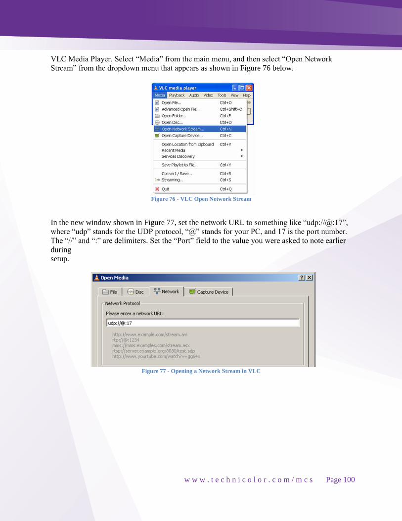
w w w . t e c h n i c o l o r . c o m / m c s
Page 100
VLC Media Player. Select “Media” from the main menu, and then select “Open Network
Stream” from the dropdown menu that appears as shown in Figure 76 below.
Figure 76 - VLC Open Network Stream
In the new window shown in Figure 77, set the network URL to something like “udp://@:17”,
where “udp” stands for the UDP protocol, “@” stands for your PC, and 17 is the port number.
The “//” and “:” are delimiters. Set the “Port” field to the value you were asked to note earlier
during
setup.
Figure 77 - Opening a Network Stream in VLC

w w w . t e c h n i c o l o r . c o m / m c s
Page 101
If you have set up all your connections as directed, VLC Media Player should start streaming
video output from channel 100. The resulting screen should look similar to the one shown in
Figure 78.
Figure 78 - Streaming Video with VLC

w w w . t e c h n i c o l o r . c o m / m c s
Page 102
14.2 Fixing an Unresponsive Card
If, in the event of a catastrophic power fail or other “glitch” event during software updates , the
COM46 card becomes unresponsive. It is possible to reprogram the card with a working copy of
the flash image. The TFTP server described in this manual, Tftpd32, also contains a BOOTP
server. If a COM46 boots and find it does not have a valid application image resident in flash,
will attempt to find an image using the BOOTP protocol. If it finds a BOOTP server on the
network with a valid operating image it will download the image and reprogram the flash so
that at the next reboot it will recover full operating capabilities.
Figure 79 shows how to enable BOOTP in Tftpd32 the Current Directory field should have the
name of the directory in which the application image is stored. The Server interface field should
have the IP address of the host machine on which the image directory resides. When these fields
are correct, press the ‘Settings’ button and select the ‘DHCP’ tab.
Figure 79 - TFTP Main Page
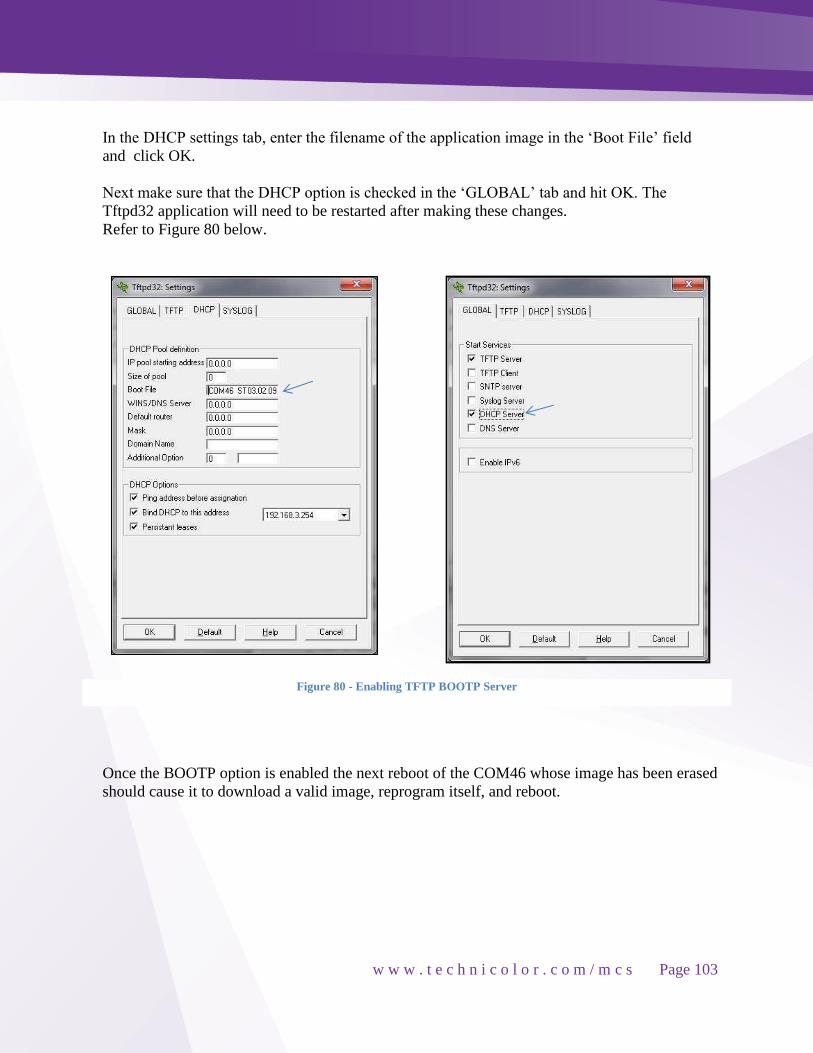
w w w . t e c h n i c o l o r . c o m / m c s
Page 103
In the DHCP settings tab, enter the filename of the application image in the ‘Boot File’ field
and click OK.
Next make sure that the DHCP option is checked in the ‘GLOBAL’ tab and hit OK. The
Tftpd32 application will need to be restarted after making these changes.
Refer to Figure 80 below.
Once the BOOTP option is enabled the next reboot of the COM46 whose image has been erased
should cause it to download a valid image, reprogram itself, and reboot.
Figure 80 - Enabling TFTP BOOTP Server

w w w . t e c h n i c o l o r . c o m / m c s
Page 104
15 Preventing Pro:Idiom Key Loss
There are two mechanisms which may cause Pro:Idiom key loss in some commercial television
sets that have been identified to us by LG
Unapproved mapping or remapping of PIDs
Off air (OA) ATSC receivers may use PIDs which conflict with PIDs in use in Pro:Idiom
licensed systems.
External EdgeQAMs may map or remap PIDs in violation of the Pro:Idiom (P:I) licensing
agreement.
Other unapproved digital video equipment may also use PIDs which conflict with P:I
licensed equipment.
TV set power on sequencing design problems
A very small number of TV set models are known to have power up sequencing issues that
cause the Pro:Idiom licensed decryptors to operate improperly. The manufacturers of these
sets have taken strong corrective action measures to update them. Contact your specific set’s
manufacturer for details.
15.1 PID Mapping at the COM46 Receiver
Pro:Idiom PIDs are in a protected range
Channel 1 AUDIO PID = 0x30 Channel 2
VIDEO PID = 0x27 VIDEO PID = 0x27
AUDIO PID = 0x30 AUDIO PID = 0x30
Pro:Idiom PID = 0x105A AUDIO PID = 0x31
Pro:Idiom PID = 0x105A
PID remapping at the edgeQAM
Pro:Idiom PIDs have been remapped and overlap with Audio PIDs on other channels
Channel 1 Channel 2
VIDEO PID = 0x13 VIDEO PID = 0x13
AUDIO PID = 0x18 AUDIO PID = 0x18
Pro:Idiom PID = 0x1A AUDIO PID = 0x1A
Pro:Idiom PID = 0x1A

w w w . t e c h n i c o l o r . c o m / m c s
Page 105
15.2 Best Practices to Avoid Key Loss
ATSC off air signals in the RF system can cause Pro:Idiom key loss if not mapped correctly.
When a TV switches from an off air channel to a Pro:Idiom channel the tuner may try and sent
the second audio programing (SAP) PIDS to the Pro:Idiom decryption circuits. This may cause
the TV to loss it’s Pro:Idiom keys.
Broadcast off air (OA) channels MUST NOT be placed adjacent to P:I protected channels
in the channel map. It does not matter where the physical channels are located, only whether
they are mapped to adjacent channels in the TV lineup.
A non-P:I, non-off air channel MUST be placed in the channel map between any broadcast
channel and a Pro:Idiom protected channel.
The COM2000 EPG, Home Screen or locally inserted channels makes a good buffer.
Analog SMATV channels can also be used as buffers.
Channel map in Figure 81 below show improper mapping of channels with off air and
Pro:Idiom programming on adjacent channels
Figure 81- Improper mapping of off air channels

w w w . t e c h n i c o l o r . c o m / m c s
Page 106
Channel map in Figure 82below shows correct lineup with analog or non Pro:Idiom channels
between off air and Pro:Idiom programming.
Figure 82 - Correct Channel Mapping to Prevent P.I. Key Loss
15.3 EdgeQAM PID remapping
A number of edgeQAM products have been designed specifically to work in Pro:Idiom systems
and are known to correctly manage Pro:Idiom Key Management message PIDs including but
not limited to Technicolor’s QAM6 and Video Propulsion’s Floodgate. Check with other
manufacturers regarding their equipment.
Two other commonly used edgeQAMs from Harmonic Lightwave, the NSG9116 and the
NSG9000, are known to employ PID remapping schemes which can create issues in distribution
networks using Pro:Idiom if not configured properly. The port mapping method which, while it
is not strictly within the Pro:Idiom guidelines, does avoid PID reuse which has been shown to
break P:I keys.
When using Harmonic edgeQAMs in the paradigm mode the position of the UDP port in the
list of ports available for a given channel sets the first digit of the PID value.
If you pick the first available UDP port value for a given channel all the PID values will
start with one, if you pick the second available port value all the PID values will start with
two, etc.

w w w . t e c h n i c o l o r . c o m / m c s
Page 107
Reuse of the same PID value is a major contributing factor in key loss and should be
avoided when mapping out the IP and port scheme used to send the data to the QAM.
DO NOT USE THE FIRST TWO UDP PORTS AVAILABLE OVER AND OVER
AGAIN. Channels that are set up this way will have PID values 10, 13, 18 and 19 or 20, 23,
28 and 29 associated with them.
Figure 83 shows a Harmonic QAM setup with incorrect PID remapping
Figure 83 - Harmonic Setup with Incorrect PID Mapping

w w w . t e c h n i c o l o r . c o m / m c s
Page 108
Figure 84 shows correct PID mapping on a Harmonic QAM
Figure 84 - Correct PID Remapping
Contact your distributor or the Edge QAM manufacturer for further support.
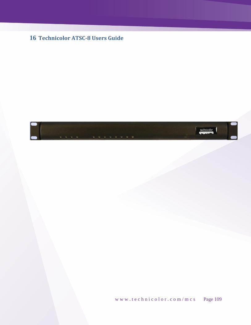
w w w . t e c h n i c o l o r . c o m / m c s
Page 109
16 Technicolor ATSC-8 Users Guide

w w w . t e c h n i c o l o r . c o m / m c s
Page 110
16.1 Introduction
This document describes the process and procedures for integrating the ATSC-8 product with
the COM2000 digital head-end system. The ATSC-8, available from Technicolor, will allow for
the reception of over-the-air broadcasts of digital broadcasts and output of this content over an
Internet Protocol (IP) output. Used in combination with a COM2000 system containing a
QAM6 EdgeQAM, this IP output can be modulated over a digital QAM network in combination
with DIRECTV premium programming if COM46 or COM46-FLX receivers are used.
16.2 Over-the-Air Broadcasts ATSC replaced NTSC broadcasts in the US in 2009 and is the primary transmission for local
digital broadcasts of major network stations. ATSC signals use the same 6MHz bandwidth as
analog NTSC television channels, but are able to provide many programs within this digital
broadcast contained on sub-channels. For instance, many broadcasters will have a main channel
located in the .1 sub-channel, and provide other secondary channels on .2 and .3 sub-channels.
Terrestrial broadcasters use an 8VSB modulation to carry 19.39Mbit/s, typically containing
MPEG2 encoded content.
16.3 Advantages of ATSC Broadcast Channels
ATSC broadcasts don’t require any content protection to be added when they are re-
broadcast in a local cable environment. This allows providers to deliver HD programming
“in-the-clear” to TVs. Combined with the COM24-FLX card providing DIRECTV SD
programming, also “in-the-clear”, an entire channel ring could be set up with mixed HD and
SD programming.
ATSC broadcasts are available for free in nearly every US city and only require a simple
antenna to receive. To see if ATSC broadcasts are available in your area, you can visit
http://dtv.gov/stationlist.htm and search on your zip code.
Most major local networks broadcast a second or third local channel which contains
important weather related content, local sports, and secondary programming of value to that
local market. These secondary channels are not typically available on satellite or cable
broadcasts.

w w w . t e c h n i c o l o r . c o m / m c s
Page 111
16.4 Getting Started
Antenna Selection
Installation of the ATSC8 is assumed to be done by trained installers with a strong
understanding of off-air antenna and distribution systems. For reference some information is
offered below:
Some issues to consider when planning an installation and selecting and antenna:
Determine local off air channels
There are multiple web sites which will provide information on available OTA channels by
market.
FCC Reception Maps: http://transition.fcc.gov/mb/engineering/dtvmaps/
Antennaweb.org http://www.antennaweb.org/default.aspx
Note RF transmission frequencies of OTA signals.
Many markets still us VHF frequencies. Determine what frequencies you will be using and
select an antenna(s) accordingly.
16.5 Site Survey
Factors to consider:
Distance from the transmission tower(s)
o Close proximity to a transmission tower does not always guarantee good reception.
Large buildings, mountains, or large bodies of water may create multipath interference.
Multiple transmission towers will probably require multiple antennas.
Use industry standard practices for spacing and combining of signals.
National and local grounding / bonding requirements and lightning protection.
Never work with an antenna near overhead electrical lines or if thundershowers are forecast.

w w w . t e c h n i c o l o r . c o m / m c s
Page 112
Determine available channels
As part of the site survey connect a TV to an antenna and auto-program in off air mode. The
TV will lock onto all available channels.
Monitor all channels you plan on using to verify consistent signal quality.
Document all channel information in a workbook file similar to the one below:
QAM PORT PLUS 256 VIR CH OTA RF CALL SIGN NETWORK TUNER IP-TUNER# HOTEL DIST CH
6-1 25 WRTV ABC 6-1
6-2 25 HTSN Local Sports 6-2
6-3 25 LWN Living Well 6-3
8-1 9 WISH Independent 8-1
8-2 9 LWS Local Weather 8-2
8-3 9 RADAR Weather Radar 8-3
13-1 13 WTRD NBC 13-1
13-2 13 COZI Independent 13-2
13-3 13 MeTV 13-3
20-1 21 WFYI 1 PBS1 20-1
20-2 21 WFYI 2 PBS2 20-2
20-3 21 WFYI CR PBS3 20-3
23-1 23 WNDY MNT 23-1
23-2 23 BOUNCE 23-2
29-1 29 WTTK CBS 29-1
29-2 29 WTTK 4 Independent 29-2
59-1 45 WXIN FOX 59-1
59-2 45 ANTENNA Antenna TV 59-2
59-3 45 THIS This TV 59-3

w w w . t e c h n i c o l o r . c o m / m c s
Page 113
16.6 ATSC-8 Programming
The ATSC-8 can be programmed in one of two fashions:
1. Each tuner can generate one off-air channel that can be mapped using the COM2000 EPG /
PSIP functions.
2. Each tuner can pass an off-air channel with all sub-channels and PSIP information. This
prevents mapping, the channels will need to be in the lineup on their virtual off air channel.
The ATSC-8 comes packaged with the following:
ATSC-8
Power supply cord
4 x 6-foot Ethernet cables
Pros Cons
Channels can be mapped in the EPG and PSIP information will reflect channel mapping. Two channels per QAM 8 channels = 4 QAMS
Maximum of 8 channels can be used.
Pros Cons
All sub-channels for each RF channel are displayed.
Each RF channel with all sub-channels occupies a QAM. 8 RF channels = 8 QAMS.
Larger channel lineup. Each OTA RF channel will pass all sub channels to hotel lineup. Local weather radar, foreign language channels, local sports etc.
PSIP information is passed through the system requiring the channels to remain on the virtual numbers on the OTA channel.
A COM 2000 with 48 channels will use 16 QAMS for DIRECTV. Leaving 8 QAMS for OTA.
Map the DIRECTV channels to their DIRECT channel assignment. Giving the user the familiar DIRECTV experience. CNN 202 ESPN 206
Off air channels that are common with DIRECTV can be mapped to the same channel in the guide.
Additional local OTAs can be programmed in the guide and location only. (no guide data)

w w w . t e c h n i c o l o r . c o m / m c s
Page 114
16.7 ATSC-8 Installation
Front LED Indicators
A Power/Network – 4 1. Tuner 1 2. Tuner 2 B Power/Network – 3 3. Tuner 3 4. Tuner 4 C Power/Network – 2 5. Tuner 5 6. Tuner 6 D Power/Network – 1 7. Tuner 7 8. Tuner 8
Power/Network LED:
Green: The ATSC-8 is powered on and connected to the network.
Flashing Green: The ATSC-8 is powered on and working to obtain an IP address from the
network. If the PC is connected directly to the ATSC-8, then the light will continue to blink
until the PC makes contact with the ATSC-8.
Red: Powered on, No Network Link.
Tuner LED:
Off: The tuner is not in use.
Green: The tuner is in use, tuned to a channel, and streaming data.
Flashing: The tuner is reserved for use, but is not actively streaming data.
A B C D 1 2 3 4 5 6 7 8
75 ohm Antenna inputs
Ethernet connections
Power Switch
Power Cable
Figure 85 - ATSC-8 Back Panel
Figure 86 - ATSC-8 Front panel

w w w . t e c h n i c o l o r . c o m / m c s
Page 115
16.8 Connection to the COM2000
Mounting
The ATSC-8 is rack mountable and can be easily mounted in the same location as the
COM2000 system. It is recommended that at least 1RU of space be left between the ATSC-8,
the COM2000, and any other components so that each component will receive good air-flow in
the mounting location.
Connecting an Antenna
The ATSC-8 has 4 RF connectors for inputting antenna signals to the 4 dual tuners. Connect the
antenna input into a 2 GHz 4-way splitter with the outputs of the splitter going to each of the RF
connectors on the ATSC-8. In some locations an amplifier may be required between the antenna
and splitter for best reception.
Connecting the Network
The ATSC-8 has 4 Ethernet connectors for outputting the IP video streams. Connect each of the
4 Ethernet connectors to an external Gigabit Switch with at least 5 open ports. Connect the 5th
port from the 5-port gigabit switch to one of the two Gigabit Ethernet ports on the COM360
chassis.
Refer to Figure 89 for connection details
NOTE: ATSC channels typically have much higher bitrates than DIRECTV HD channels with
data rates around 14-18 Mbits/s. In order to send 8 channels to the QAM6, the Gigabit Ethernet-
1 port must be used to insure that the data is received.
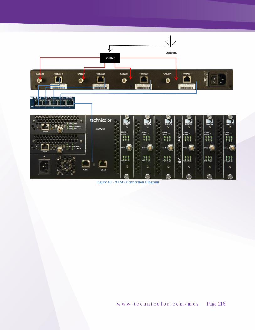
w w w . t e c h n i c o l o r . c o m / m c s
Page 116
Figure 89 - ATSC Connection Diagram
splitter
Antenna

w w w . t e c h n i c o l o r . c o m / m c s
Page 117
16.9 Check / Update the ATSC-8 firmware version Note: COM46 software must be set to version 3.2.19 or newer.
Internal to the ATSC-8 are 4 tuner modules. To properly interact with the with the COM2000
interface the firmware should always be set to version 20120405. The firmware and the
HDHomeRun software utility required to update the firmware are available on the Technicolor
After Market Support web site, or through your distributor. Install the utility and save the
firmware to a folder on your PC.
16.10 HDHomeRun Tech Configuration Utility Upon opening the HDHomeRun software will search for, and discover the active devices. They are
listed by MAC address in the Device View tab.
Figure 90 - HDHomeRun Tech Configuration Utility
From the Tools menu select Upgrade Firmware.
Click the Select button and navigate to the location of the HDHomeRun firmware.
Figure 91 - HDHomeRun Upgrade Firmware Tab
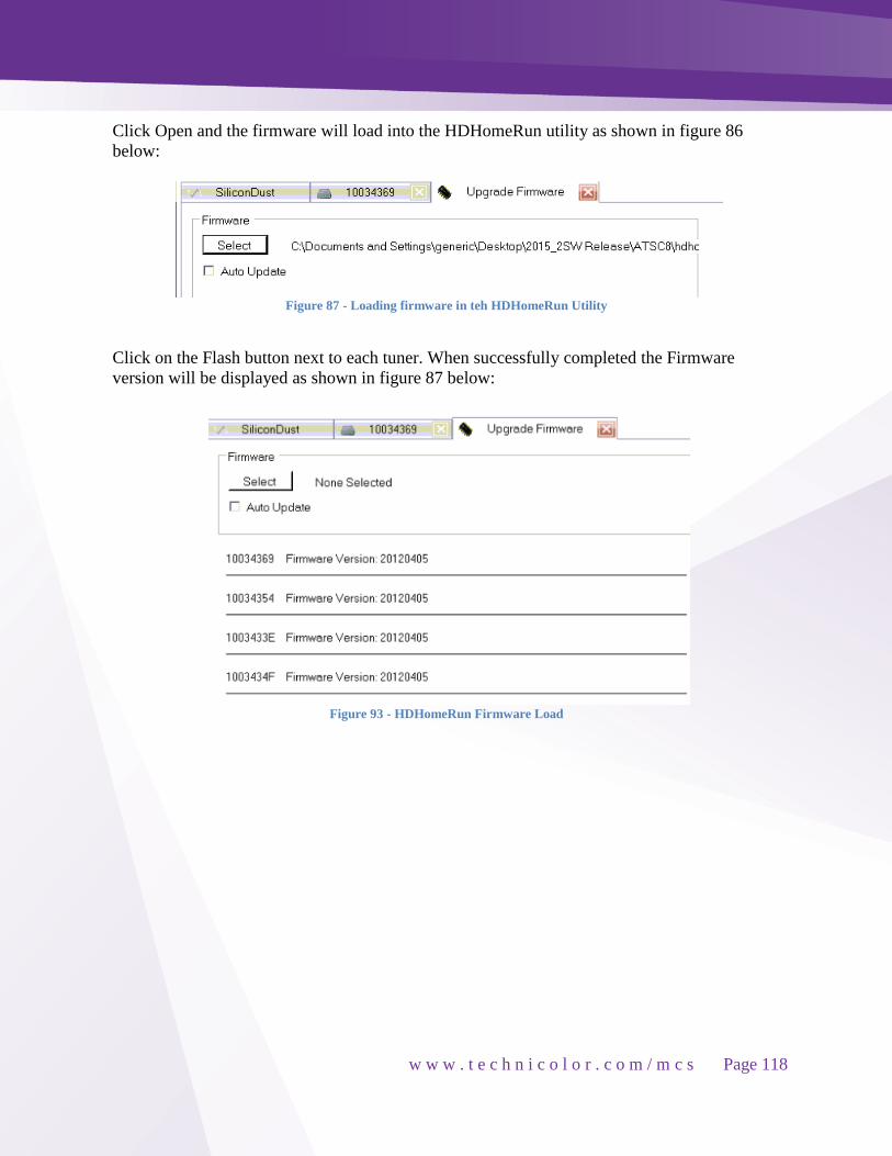
w w w . t e c h n i c o l o r . c o m / m c s
Page 118
Click Open and the firmware will load into the HDHomeRun utility as shown in figure 86
below:
Figure 87 - Loading firmware in teh HDHomeRun Utility
Click on the Flash button next to each tuner. When successfully completed the Firmware
version will be displayed as shown in figure 87 below:
Figure 93 - HDHomeRun Firmware Load

w w w . t e c h n i c o l o r . c o m / m c s
Page 119
16.11 Configuring the ATSC-8
The ATSC-8 is fully controlled and commanded by the COM2000. From the COM2000
interface, to access the ATSC control, select the ATSC tab as shown in Figure .
Figure 94 - Accessing the ATSC Tab
16.12 Discover the IP Addresses of the ATSC Tuner Modules
When the ATSC-8 is shipped from Technicolor, it will be in DHCP mode and expect to get
assigned an IP address from a router. Since our connection diagrams and common installation
practices do not include a router or DHCP server, the IP addresses may not be assigned. The
ATSC-8 will also generate an Auto-IP address such that a PC connected directly to the unit
without a router can communicate to the device.
Each ATSC-8 has 4 tuning modules containing 2 tuners each. Each Tuning module can have
two unique IP addresses, so in total, the ATSC-8 will have 8 unique IP addresses (two for each
tuning module). When first connecting to the ATSC-8 or to see what the IP addresses of the
tuners are, you can press the DISCOVER button on the bottom of the ATSC page. Figure
displays the result from a Discover inquiry. One address for each module is the Auto-IP address
assigned by the module itself, the other can be Auto-IP, static or assigned by DHCP.

w w w . t e c h n i c o l o r . c o m / m c s
Page 120
Figure 95 - ATSC tuner discovery
Figure shows that 8 total IP addresses were found, and since each of the 4 tuner modules has 2
possible IP addresses, the 2 addresses are displayed.
16.13 Changing the IP Addresses of the Tuners
You may change the IP addresses of the tuners to a range within the same IP configuration of
the COM2000 by using the SET button on the ATSC page. You must first type in the base
number for the assignment, then hit the SET button. For instance, if you’d like the IP addresses
to be in a range starting at 192.168.3.50, then use 192.168.3.50 as the base address. See Figure
below.
With the following result:
Figure 97 - Changing Tuner IP addresses

w w w . t e c h n i c o l o r . c o m / m c s
Page 121
From our previous discovery, we showed both the known IP addresses and the AutoIP
addresses for each of the 4 addressable tuners in the ATSC-8. When making the requested IP
address change, each device receives 2 commands to change the IP with the second command
resulting in the change. As shown in Figure , the 4 tuners will have an IP address of
192.168.3.54, 192.168.3.55, 192.168.3.56 and 192.168.3.57. You can verify by again using the
DISCOVER button from the ATSC page. *Note that although the above screen shows the Auto-
IP addresses being changed, in fact they are not. A new DISCOVER command will show only
the variable addresses that have actually been changed.
New IPs
Figure 99 - ATSC Discover
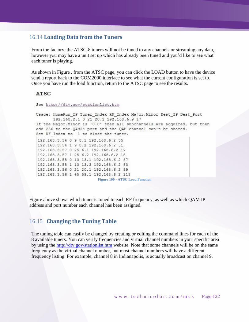
w w w . t e c h n i c o l o r . c o m / m c s
Page 122
16.14 Loading Data from the Tuners
From the factory, the ATSC-8 tuners will not be tuned to any channels or streaming any data,
however you may have a unit set up which has already been tuned and you’d like to see what
each tuner is playing.
As shown in Figure , from the ATSC page, you can click the LOAD button to have the device
send a report back to the COM2000 interface to see what the current configuration is set to.
Once you have run the load function, return to the ATSC page to see the results.
Figure 100 - ATSC Load Function
Figure above shows which tuner is tuned to each RF frequency, as well as which QAM IP
address and port number each channel has been assigned.
16.15 Changing the Tuning Table
The tuning table can easily be changed by creating or editing the command lines for each of the
8 available tuners. You can verify frequencies and virtual channel numbers in your specific area
by using the http://dtv.gov/stationlist.htm website. Note that some channels will be on the same
frequency as the virtual channel number, but most channel numbers will have a different
frequency listing. For example, channel 8 in Indianapolis, is actually broadcast on channel 9.

w w w . t e c h n i c o l o r . c o m / m c s
Page 123
Each listing in the tune table will need all the required fields entered.
Figure 101 below is an entry along with a description of what each field contains.
192.168.3.54 0 9 8.1 192.168.6.2 35
192.168.3.54 = IP address of the tuner to be set.
0 = Tuner index. There are 2 tuners per IP address, so this is either 0 or 1.
9 = Actual RF channel number of the broadcasting station.
8.1 = Virtual channel number and program stream desired.
192.168.6.2 = IP Address of the QAM to output the tuned channel.
35 = Port number of the QAM corresponding to the desired QAM channel which will carry the
tuned ATSC channel.
Once you have developed a tune table which will work in your area with the appropriate data
entered for each of the tuners you need in your system, press the SAVE button, then the RUN
button to make this active on the ATSC-8. You should see this change immediately if properly
connected to a QAM.
Figure 101 - ATSC Tune Table

w w w . t e c h n i c o l o r . c o m / m c s
Page 124
16.16 QUERY Command
The ATSC-8 is able to Query the tuned channels once they have been set up so you can view
the signal strength of each frequency. This could be especially helpful if you aren’t seeing
channels that you’d expect to or need to adjust your input antenna.
Figure 88 - Query Command Results
In Figure above you can see the following:
Channel 9 is not tuned (lock=none)
Channel 25 is tuned and showing details of all the programming available on that digital
channel.
You can see:
Signal Strength (ss)
Signal to Noise Quotient (snq)
Signal Quality (seq)
Bit and Packet rates (bps & pps)
Lock = none
Signal Strength SnR Signal Quality % Bit & Packet Rate
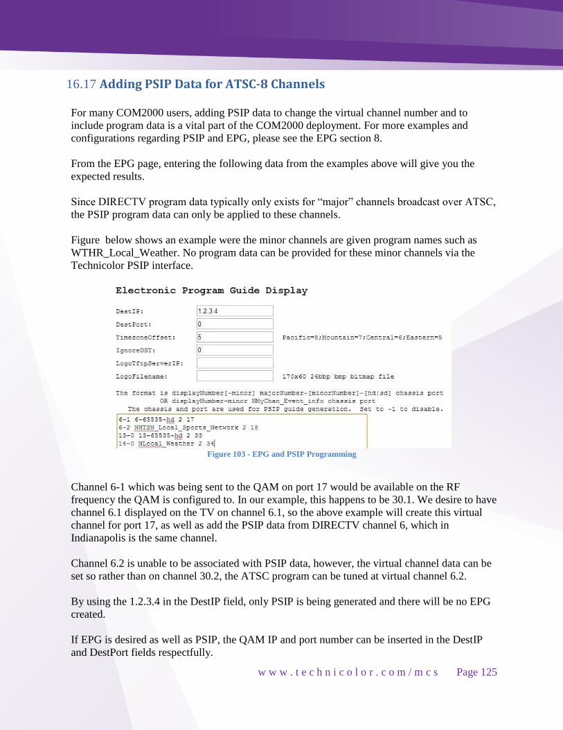
w w w . t e c h n i c o l o r . c o m / m c s
Page 125
16.17 Adding PSIP Data for ATSC-8 Channels
For many COM2000 users, adding PSIP data to change the virtual channel number and to
include program data is a vital part of the COM2000 deployment. For more examples and
configurations regarding PSIP and EPG, please see the EPG section 8.
From the EPG page, entering the following data from the examples above will give you the
expected results.
Since DIRECTV program data typically only exists for “major” channels broadcast over ATSC,
the PSIP program data can only be applied to these channels.
Figure below shows an example were the minor channels are given program names such as
WTHR_Local_Weather. No program data can be provided for these minor channels via the
Technicolor PSIP interface.
Figure 103 - EPG and PSIP Programming
Channel 6-1 which was being sent to the QAM on port 17 would be available on the RF
frequency the QAM is configured to. In our example, this happens to be 30.1. We desire to have
channel 6.1 displayed on the TV on channel 6.1, so the above example will create this virtual
channel for port 17, as well as add the PSIP data from DIRECTV channel 6, which in
Indianapolis is the same channel.
Channel 6.2 is unable to be associated with PSIP data, however, the virtual channel data can be
set so rather than on channel 30.2, the ATSC program can be tuned at virtual channel 6.2.
By using the 1.2.3.4 in the DestIP field, only PSIP is being generated and there will be no EPG
created.
If EPG is desired as well as PSIP, the QAM IP and port number can be inserted in the DestIP
and DestPort fields respectfully.

w w w . t e c h n i c o l o r . c o m / m c s
Page 126
17 Addendums
17.1 Open Software Notification The software of this product may contain certain open source software modules, which are
subject to Open Source Software license terms (see https://opensource.org/osd for definition).
Such Open Source Software components and/or versions may change in the future versions of
the software product.
A list of the Open Source Software used or provided as embedded into the current software of
the product and their corresponding licenses and version number are, to the extent required by
applicable terms, available on Technicolor's website at the following address:
http://www.technicolor.com/en/hi/minisites/open-software
or at another address as Technicolor may provide from time to time.
If and where applicable, depending on the terms of the applicable Open Source Software
licenses, the source code of the Open Source Software is available for free upon request. For avoidance of doubt, Open Source Software is only licensed by the original owner of the
Open Source Software under the terms set forth in the designated Open Source License.