Embed Size (px)
Citation preview
REQUIREMENT 1 (81)
Created by (name and organisational unit) Document ID Case number
Karlsson, Robert, UHau konsult [Ärendenummer] Approved by Document date Version
Manager, VO Maintenance 0.1 Document title
Technical system standard for high-speed tracks
This document forms part of the Swedish Transport Administration's safety management system for
railways. See specific rules for the administration of safety permits.
TRVK Technical system standard for high-speed tracks (TDOK 2014:0159) is a Swedish Transport
Administration document which includes the Swedish Transport Administration's technical
requirements for formulation, design, inspection and maintenance of high-speed railways. TRVK
Technical system standard for high-speed tracks is a document of Requirements type. TRVK Technical
system standard for high-speed tracks forms part of the Swedish Transport Administration's
installation management system. Questions relating to these regulations should be submitted in the
first instance to Christian Eriksson at the Swedish Transport Administration.
TRVK Technical system standard for high-speed tracks must be applied as of 26 March 2014. These
regulations do not replace any earlier regulations, but involve new requirements for high-speed
railways (tracks operating at MPS 250-320 km/h). Deviations from these technical requirements are
managed by the project New technical system standard for high-speed tracks.
In case of any inconsistency between this document and the corresponding
document in Swedish, the Swedish version shall prevail.
REQUIREMENTS 2 (81)
Document ID Case number Version
[Ärendenummer] 0.1
Contents
1 Purpose and scope ............................................................................................................................ 10
2 Definitions and abbreviations ........................................................................................................... 11
2.1 Definitions ............................................................................................................................................ 11
2.2 Abbreviations ....................................................................................................................................... 13
3 Requirements for planning ................................................................................................................ 15
3.1 Formalities ........................................................................................................................................... 15
3.2 Load-bearing capacity, stability and durability ...................................................................................... 15
3.3 Safety in service ................................................................................................................................... 15
3.3.1 Physical barrier .................................................................................................................................... 15
3.3.2 Requirements for traffic safety ............................................................................................................. 15
3.4 Environment and health ....................................................................................................................... 15
3.4.1 Fauna passages and similar ................................................................................................................ 15
3.4.2 Requirements for safety guards ........................................................................................................... 16
3.5 Punctuality ........................................................................................................................................... 16
3.6 Capacity ............................................................................................................................................... 16
3.7 Robustness .......................................................................................................................................... 17
3.7.1 Making trees safe ................................................................................................................................. 17
3.7.2 Requirements for information security .................................................................................................. 17
3.7.3 Requirements for crisis management ................................................................................................... 17
3.7.4 Miscellaneous ...................................................................................................................................... 17
3.8 Usability ............................................................................................................................................... 17
3.9 Optimised life cycle cost ....................................................................................................................... 17
3.10 Interfaces between components and between installations ................................................................. 18
3.11 Interfaces with vehicles ........................................................................................................................ 18
3.12 Work on the installation and traffic operation at the work site .............................................................. 18
3.13 Productivity and efficiency .................................................................................................................... 18
3.14 Special requirements ........................................................................................................................... 18
3.14.1 Requirements for electrical safety ........................................................................................................ 18
4 Requirements for bridges.................................................................................................................. 19
4.1 Formalities ........................................................................................................................................... 19
4.2 Load-bearing capacity, stability and durability ...................................................................................... 19
4.2.1 General ................................................................................................................................................ 19
4.2.2 Bridge types ......................................................................................................................................... 20
4.2.3 Traffic load on bridges .......................................................................................................................... 21
4.2.3.1 Train load models ................................................................................................................................. 21
4.2.3.2 Load distribution ................................................................................................................................... 21
4.2.3.3 Dynamic magnification factor ............................................................................................................... 21
4.2.4 Combined response on load-bearing structures and tracks from variable loads .................................. 21
4.2.5 Dynamic analyses ................................................................................................................................ 22
4.2.5.1 Checking whether dynamic analysis is required .................................................................................. 22
REQUIREMENTS 3 (81)
Document ID Case number Version
[Ärendenummer] 0.1
4.2.5.2 Additional fatigue verification when dynamic analysis is required ........................................................ 22
4.2.5.3 Verification of serviceability limit state .................................................................................................. 22
4.2.5.4 Calculation models ............................................................................................................................... 23
4.2.5.5 Damping ............................................................................................................................................... 23
4.2.5.6 Rigidity of load-bearing structures and supports .................................................................................. 23
4.2.5.7 Mass .................................................................................................................................................... 24
4.3 Safety in service ................................................................................................................................... 24
4.4 Environment and health ....................................................................................................................... 24
4.5 Punctuality ........................................................................................................................................... 24
4.6 Capacity ............................................................................................................................................... 24
4.7 Robustness .......................................................................................................................................... 24
4.7.1 Measurement and detection ................................................................................................................. 24
4.8 Usability ............................................................................................................................................... 25
4.9 Optimised life cycle cost ....................................................................................................................... 25
4.10 Interfaces between components and between installations ................................................................. 25
4.11 Interfaces with vehicles ........................................................................................................................ 25
4.12 Work on the installation and traffic operation at the work site .............................................................. 25
4.13 Productivity and efficiency .................................................................................................................... 25
4.14 Special requirements ........................................................................................................................... 25
5 Requirements for tunnels .................................................................................................................. 26
5.1 Formalities ........................................................................................................................................... 26
5.2 Load-bearing capacity, stability and durability ...................................................................................... 26
5.2.1 Basic dimensioning requirements ........................................................................................................ 26
5.2.2 Loads ................................................................................................................................................... 26
5.3 Safety in service ................................................................................................................................... 26
5.3.1 Walkways ............................................................................................................................................. 26
5.4 Environment and health ....................................................................................................................... 27
5.5 Punctuality ........................................................................................................................................... 27
5.6 Capacity ............................................................................................................................................... 27
5.7 Robustness .......................................................................................................................................... 27
5.7.1 Measurement and detection ................................................................................................................. 27
5.8 Usability ............................................................................................................................................... 27
5.9 Optimised life cycle cost ....................................................................................................................... 27
5.10 Interfaces between components and between installations ................................................................. 28
5.10.1 Boundary to track substructure ............................................................................................................ 28
5.10.2 Boundary to track superstructure ......................................................................................................... 28
5.11 Interfaces with vehicles ........................................................................................................................ 28
5.12 Work on the installation and traffic operation at the work site .............................................................. 28
5.13 Productivity and efficiency .................................................................................................................... 28
5.14 Special requirements ........................................................................................................................... 28
6 Requirements for power supply ....................................................................................................... 29
6.1 Formalities ........................................................................................................................................... 29
REQUIREMENTS 4 (81)
Document ID Case number Version
[Ärendenummer] 0.1
6.2 Load-bearing capacity, stability and durability ...................................................................................... 29
6.3 Safety in service ................................................................................................................................... 29
6.4 Environment and health ....................................................................................................................... 29
6.5 Punctuality ........................................................................................................................................... 29
6.6 Capacity ............................................................................................................................................... 30
6.6.1 Infeed point .......................................................................................................................................... 30
6.6.2 Catenary system .................................................................................................................................. 30
6.6.2.1 Catenary system - electric .................................................................................................................... 30
6.6.2.2 Catenary system - mechanical ............................................................................................................. 30
6.6.3 Auxiliary power system ........................................................................................................................ 31
6.7 Robustness .......................................................................................................................................... 32
6.7.1 Measurement and detection ................................................................................................................. 32
6.7.2 Climate assurance ............................................................................................................................... 32
6.7.3 Collective power supply ....................................................................................................................... 33
6.7.4 Faults in catenary systems ................................................................................................................... 33
6.7.5 Auxiliary power system ........................................................................................................................ 33
6.8 Usability ............................................................................................................................................... 33
6.9 Optimised life cycle cost ....................................................................................................................... 33
6.10 Interfaces between components and between installations ................................................................. 34
6.11 Interfaces with vehicles ........................................................................................................................ 34
6.12 Work on the installation and traffic operation at the work site .............................................................. 34
6.13 Productivity and efficiency .................................................................................................................... 34
6.14 Special requirements ........................................................................................................................... 34
7 Requirements for track substructure and supporting foundation ................................................. 35
7.1 Formalities ........................................................................................................................................... 35
7.2 Load-bearing capacity, stability and durability ...................................................................................... 35
7.2.1 Basic dimensioning requirements ........................................................................................................ 35
7.2.1.1 Essential definition of ballastless track ................................................................................................. 35
7.2.1.2 Service life for geostructures ................................................................................................................ 35
7.2.1.3 Design train speed for geostructures ................................................................................................... 35
7.2.1.4 Design train loads for geostructures ..................................................................................................... 35
7.2.1.5 Design frost recurrence ........................................................................................................................ 36
7.2.2 Track substructure ............................................................................................................................... 36
7.2.2.1 Frost insulation layer ............................................................................................................................ 36
7.2.2.2 Fill ........................................................................................................................................................ 36
7.2.2.3 Transitions ........................................................................................................................................... 37
7.2.3 Supporting foundation .......................................................................................................................... 37
7.2.3.1 Geotechnical category and safety class ............................................................................................... 37
7.2.3.2 Bearing capacity beneath railway embankments ................................................................................. 38
7.2.3.3 Stability of geostructures ...................................................................................................................... 38
7.2.3.4 Settlements .......................................................................................................................................... 38
7.2.3.5 Track vibrations .................................................................................................................................... 38
REQUIREMENTS 5 (81)
Document ID Case number Version
[Ärendenummer] 0.1
7.2.3.6 Soil and rock excavation ...................................................................................................................... 38
7.2.3.7 Light fills/ground reinforcements .......................................................................................................... 38
7.2.4 Catenary foundation ............................................................................................................................. 39
7.3 Safety in service ................................................................................................................................... 39
7.4 Environment and health ....................................................................................................................... 39
7.4.1 Dewatering ........................................................................................................................................... 39
7.5 Punctuality ........................................................................................................................................... 40
7.6 Capacity ............................................................................................................................................... 40
7.7 Robustness .......................................................................................................................................... 40
7.7.1 Measurement and detection ................................................................................................................. 40
7.7.2 Climate assurance ............................................................................................................................... 40
7.8 Usability ............................................................................................................................................... 40
7.9 Optimised life cycle cost ....................................................................................................................... 41
7.10 Interfaces between components and between installations ................................................................. 41
7.11 Interfaces with vehicles ........................................................................................................................ 41
7.12 Work on the installation and traffic operation at the work site .............................................................. 41
7.13 Productivity and efficiency .................................................................................................................... 41
7.14 Special requirements ........................................................................................................................... 41
8 Requirements for track superstructure ............................................................................................ 42
8.1 Formalities ........................................................................................................................................... 42
8.2 Load-bearing capacity, stability and durability ...................................................................................... 42
8.2.1 General ................................................................................................................................................ 42
8.2.2 Track resistance and loads .................................................................................................................. 42
8.2.2.1 Track resistance for vertical loads ........................................................................................................ 42
8.2.2.2 Track resistance for longitudinal forces ................................................................................................ 43
8.2.2.3 Track resistance for lateral forces ........................................................................................................ 43
8.2.2.4 Transition zones ................................................................................................................................... 43
8.2.2.5 Track rigidity ......................................................................................................................................... 43
8.3 Safety in service ................................................................................................................................... 44
8.3.1 Fencing ................................................................................................................................................ 44
8.4 Environment and health ....................................................................................................................... 44
8.5 Punctuality ........................................................................................................................................... 44
8.6 Capacity ............................................................................................................................................... 44
8.6.1 Length of platform ................................................................................................................................ 44
8.6.2 Width of platform .................................................................................................................................. 44
8.6.3 Platform height ..................................................................................................................................... 44
8.6.4 Platform distance from centre of track .................................................................................................. 45
8.6.5 Track design adjacent to platforms ...................................................................................................... 45
8.6.6 Other design requirements at stations ................................................................................................. 45
8.7 Robustness .......................................................................................................................................... 45
8.7.1 Measurement and detection ................................................................................................................. 46
8.7.2 Climate assurance ............................................................................................................................... 46
REQUIREMENTS 6 (81)
Document ID Case number Version
[Ärendenummer] 0.1
8.7.3 Access to the track ............................................................................................................................... 47
8.8 Usability ............................................................................................................................................... 48
8.9 Optimised life cycle cost ....................................................................................................................... 48
8.10 Interfaces between components and between installations ................................................................. 48
8.11 Interfaces with vehicles ........................................................................................................................ 48
8.11.1 General requirements .......................................................................................................................... 48
8.11.2 Design requirements, track design ....................................................................................................... 48
8.11.2.1 Infrastructure profile ............................................................................................................................. 48
8.11.2.2 Track spacing ....................................................................................................................................... 48
8.11.2.3 Inclination ............................................................................................................................................. 49
8.11.2.4 Cants .................................................................................................................................................... 49
8.11.2.5 Cant deficiency..................................................................................................................................... 49
8.11.2.6 Cant excess ......................................................................................................................................... 49
8.11.2.7 Sudden cant change ............................................................................................................................ 49
8.11.2.8 Minimum horizontal radius ................................................................................................................... 50
8.11.2.9 Minimum vertical radius ....................................................................................................................... 50
8.11.2.10 Minimum transition curve length ...................................................................................................... 50
8.11.2.11 Length of straight track or circular curves between transition curves and ramps ............................. 50
8.11.2.12 Crosswinds ...................................................................................................................................... 50
8.11.3 Track design......................................................................................................................................... 51
8.11.3.1 Absolute track position (permanent deviations)................................................................................... 51
8.11.3.2 Relative track location .......................................................................................................................... 51
8.11.3.3 Reinforcement layers ........................................................................................................................... 51
8.11.3.4 Track gauge ......................................................................................................................................... 51
8.11.3.5 Equivalent conicity ............................................................................................................................... 52
8.11.3.6 Rail quality ........................................................................................................................................... 52
8.11.3.7 Rail head profile ................................................................................................................................... 52
8.11.3.8 Rail inclination ...................................................................................................................................... 52
8.11.3.9 Sleeper spacing (spacing between support points) .............................................................................. 52
8.11.3.10 Rail fastenings ................................................................................................................................. 52
8.11.3.11 Joints ............................................................................................................................................... 52
8.11.4 Special requirements for fixed track design (ballastless) ..................................................................... 53
8.11.4.1 Maintenance requirements ................................................................................................................... 54
8.11.5 Point switches ...................................................................................................................................... 54
8.11.5.1 Geometric design of point switches ...................................................................................................... 54
8.11.5.2 Reroutable crossing ............................................................................................................................. 54
8.12 Work on the installation and traffic operation at the work site .............................................................. 54
8.13 Productivity and efficiency .................................................................................................................... 54
8.14 Special requirements ........................................................................................................................... 55
9 Requirements for signal systems ..................................................................................................... 56
9.1 Formalities ........................................................................................................................................... 56
9.2 Load-bearing capacity, stability and durability ...................................................................................... 56
REQUIREMENTS 7 (81)
Document ID Case number Version
[Ärendenummer] 0.1
9.3 Safety in service ................................................................................................................................... 57
9.4 Environment and health ....................................................................................................................... 57
9.5 Punctuality ........................................................................................................................................... 57
9.6 Capacity ............................................................................................................................................... 57
9.7 Robustness .......................................................................................................................................... 57
9.7.1 Measurement and detection ................................................................................................................. 58
9.8 Usability ............................................................................................................................................... 59
9.9 Optimised life cycle cost ....................................................................................................................... 59
9.10 Interfaces between components and between installations ................................................................. 59
9.11 Interfaces with vehicles ........................................................................................................................ 59
9.12 Work on the installation and traffic operation at the work site .............................................................. 59
9.13 Productivity and efficiency .................................................................................................................... 60
9.14 Special requirements ........................................................................................................................... 60
10 Requirements for railway traffic management systems ................................................................. 61
10.1 Formalities ........................................................................................................................................... 61
10.2 Load-bearing capacity, stability and durability ...................................................................................... 61
10.3 Safety in service ................................................................................................................................... 61
10.4 Environment and health ....................................................................................................................... 61
10.5 Punctuality ........................................................................................................................................... 61
10.6 Capacity ............................................................................................................................................... 61
10.7 Robustness .......................................................................................................................................... 61
10.7.1 Measurement and detection ................................................................................................................. 61
10.8 Usability ............................................................................................................................................... 62
10.9 Optimised life cycle cost ....................................................................................................................... 62
10.10 Interfaces between components and between installations ................................................................. 62
10.11 Interfaces with vehicles ........................................................................................................................ 62
10.12 Work on the installation and traffic operation at the work site .............................................................. 62
10.13 Productivity and efficiency .................................................................................................................... 62
10.14 Special requirements ........................................................................................................................... 62
11 Requirements for telecommunications ............................................................................................ 63
11.1 Formalities ........................................................................................................................................... 63
11.2 Load-bearing capacity, stability and durability ...................................................................................... 63
11.3 Safety in service ................................................................................................................................... 63
11.4 Environment and health ....................................................................................................................... 64
11.5 Punctuality ........................................................................................................................................... 64
11.6 Capacity ............................................................................................................................................... 64
11.7 Robustness .......................................................................................................................................... 64
11.7.1 Measurement and detection ................................................................................................................. 65
11.8 Usability ............................................................................................................................................... 66
11.9 Optimised life cycle cost ....................................................................................................................... 66
11.10 Interfaces between components and between installations ................................................................. 66
11.11 Interfaces with vehicles ........................................................................................................................ 66
REQUIREMENTS 8 (81)
Document ID Case number Version
[Ärendenummer] 0.1
11.12 Work on the installation and traffic operation at the work site .............................................................. 66
11.13 Productivity and efficiency .................................................................................................................... 67
11.14 Special requirements ........................................................................................................................... 67
12 Requirements for track design ......................................................................................................... 68
12.1 Formalities ........................................................................................................................................... 68
12.2 Load-bearing capacity, stability and durability ...................................................................................... 68
12.3 Safety in service ................................................................................................................................... 68
12.3.1 Lock systems ....................................................................................................................................... 68
12.4 Environment and health ....................................................................................................................... 68
12.4.1 Suicide and collisions with people ........................................................................................................ 68
12.4.1.1 Protective measures ............................................................................................................................ 68
12.4.1.2 Collision with animals ........................................................................................................................... 69
12.4.1.3 Alarms .................................................................................................................................................. 69
12.5 Punctuality ........................................................................................................................................... 69
12.6 Capacity ............................................................................................................................................... 69
12.6.1 Points ................................................................................................................................................... 69
12.7 Robustness .......................................................................................................................................... 70
12.7.1 Maintenance vehicles ........................................................................................................................... 70
12.7.2 Requirements for maintenance safety .................................................................................................. 70
12.7.3 Maintenance windows .......................................................................................................................... 71
12.7.4 Other requirements for maintenance .................................................................................................... 71
12.8 Usability ............................................................................................................................................... 71
12.8.1 Climate assurance ............................................................................................................................... 71
12.9 Optimised life cycle cost ....................................................................................................................... 71
12.10 Interfaces between components and between installations ................................................................. 71
12.11 Interfaces with vehicles ........................................................................................................................ 72
12.12 Work on the installation and traffic operation at the work site .............................................................. 72
12.13 Productivity and efficiency .................................................................................................................... 72
12.14 Special requirements ........................................................................................................................... 72
13 Requirements for documentation, including geometric description and labelling of the installation ............................................................................................................................................................ 73
13.1 Formalities ........................................................................................................................................... 73
13.2 Load-bearing capacity, stability and durability ...................................................................................... 73
13.3 Safety in service ................................................................................................................................... 73
13.4 Environment and health ....................................................................................................................... 73
13.5 Punctuality ........................................................................................................................................... 73
13.6 Capacity ............................................................................................................................................... 73
13.7 Robustness .......................................................................................................................................... 73
13.7.1 Installation and maintenance planning system ..................................................................................... 73
13.7.2 Reserve materials supply ..................................................................................................................... 73
13.8 Usability ............................................................................................................................................... 74
13.9 Optimised life cycle cost ....................................................................................................................... 74
REQUIREMENTS 9 (81)
Document ID Case number Version
[Ärendenummer] 0.1
13.10 Interfaces between components and between installations ................................................................. 74
13.11 Interfaces with vehicles ........................................................................................................................ 74
13.12 Work on the installation and traffic operation at the work site .............................................................. 74
13.13 Productivity and efficiency .................................................................................................................... 74
13.13.1 Documentation and instructions ........................................................................................................... 74
13.14 Special requirements ........................................................................................................................... 74
14 Appendices ......................................................................................................................................... 75
14.1 Annex 1 – Figures, tables, type sections and suchlike ......................................................................... 75
14.1.1 Figure 1 ................................................................................................................................................ 75
14.1.2 Figure 2 ................................................................................................................................................ 76
14.1.3 Figure 3 ................................................................................................................................................ 76
14.1.4 Table 1 ................................................................................................................................................. 76
15 References .......................................................................................................................................... 77
15.1 TSI ....................................................................................................................................................... 77
15.2 Other European standards and directives ............................................................................................ 77
15.3 Swedish Transport Administration requirements, recommendations and AMA .................................... 77
15.4 Swedish Transport Administration publications and reports ................................................................. 78
15.5 Laws and documents from other authorities ........................................................................................ 79
15.6 Other railway administrations ............................................................................................................... 79
15.7 Other .................................................................................................................................................... 79
16 Change log .......................................................................................................................................... 80
REQUIREMENTS 10 (81)
Document ID Case number Version
[Ärendenummer] 0.1
1 Purpose and scope
TRVK Technical system standard for high-speed tracks (TDOK 2014:0159) is a Swedish Transport
Administration document which includes the Swedish Transport Administration's technical
requirements for the planning, design, construction and operation of high-speed tracks at MPS up to
320 km/h. This document describes the technical requirements which must be met in order to achieve
the set targets of the high-speed track.
This technical system standard for high-speed tracks indicates which laws and steering documents are
applicable to the planning, design, construction and operation of high-speed railways. For this
purpose, this document presents further requirements/more stringent requirements and, where
applicable, requirements which are being revised and will probably be made more stringent, and which
control planning, design, construction and operation of high-speed railways in Sweden.
The regulations must be applied prior to procurement procedures for high-speed railway projects in
which the State, via the Swedish Transport Administration, is the client. The regulations must be
applied by project managers, traffic engineers and other relevant personnel, and also by consultants
carrying out corresponding work. In the case of turnkey contracts, these requirements must control the
contractor's design work.
The system standard aims to describe a modern high-speed railway, category 1 in accordance with
(TSI Infrastructure), adapted to Swedish conditions. This railway is designed for high-speed traffic
operating at speeds from 250 km/h up to 320 km/h. As the track will form part of the Trans-European
high-speed rail network, TEN, traffic from e.g. Hamburg via the Fehmarn Belt and
Copenhagen/Malmö to Stockholm is predicted.
Important criteria to permit the function described by the standard are:
A separate traffic system with little impact from other systems, giving maximum punctuality
and greatest capacity utilisation
Good connecting traffic
A separate track with few connections to existing main lines
Few stops
Simple infrastructure with few installation elements
A fixed track system
A modern, efficient, energy-efficient electrical system with a high level of redundancy
Signal systems with ERTMS level 2 (E2)
The installation is being designed with a view to reducing the impact of factors such as the
climate and snow
It must be possible to lay the track on viaducts where this would be advantageous from the
standpoint of land and the environment
REQUIREMENTS 11 (81)
Document ID Case number Version
[Ärendenummer] 0.1
2 Definitions and abbreviations
2.1 Definitions
Serious incident (within the work environment) An incident which in itself
presents a major risk of ill-health or accidents.
Installation (within the transport system) A space or area arranged for a
specific function together with necessary installations.
Installation cost (within investment operations) Total cost, from pilot study up
to and including handover of the installation to administration.
Corrective maintenance (within the provide the transport system field) Maintenance which is
carried out once a fault has been discovered and with a view
to ensuring that the installation is in a condition that allows it
to perform the designated function.
Operation (within the provide the transport system field) A combination
of all technical, administrative and steering measures which
support traffic operations on a section of railway and which
are not maintenance measures.
Operation site A location on the section of railway where passengers can
board or leave a train. A separate restricted area of the track
where panel operators can monitor train movements more
closely. Equipped with a signal safety installation.
Available time Agreed time for e.g. A-type protection in respect of planned
maintenance or investment.
Double track A section with two main tracks between two operation sites.
Double run One train in either direction.
Single track A section with just one main track on the line between two
operation sites. The capacity is dependent upon the passing
clearance between trains at certain locations.
Fault (in installations) The cessation of a unit's ability to perform
the required function.
Fixed track Also known as a ballastless track system. A railway
installation which is not ballasted, where the rail is mounted
on a track plate instead of sleepers. See also Track plate.
Preventive maintenance (within the provide the transport system field) Maintenance
carried out at set intervals or in accordance with prescribed
criteria with a view to reducing the likelihood of faults or
impairment of the function of an installation.
Preventive measure A measure for eliminating the cause of a potential non-
conformance or another unwanted possible situation.
Provision A generally applicable rule decided upon by the Riksdag
(Swedish parliament), the Government, another authority or a
municipality.
REQUIREMENTS 12 (81)
Document ID Case number Version
[Ärendenummer] 0.1
Administrator (in the administration model) A role which involves carrying
out operational work with one or more administration
components.
High-speed train, high-speed track Train and track standard above 250 km/h.
Infrastructure administrator An organisation which manages tracks in accordance with the
Swedish Railways Act (2004:519).
Intelligent trains Designation for trains/vehicles which have their own metering
equipment which alerts the operator in the event of faults due
to overheating, wheel wear, pantograph wear, etc.
International Union of Railways Union Internationale des Chemins de fer (UIC). Works to
promote railway transport by means of standardisations and
interaction between railway administrators, among other
things.
Railway company A company operating rail traffic in accordance with the
Swedish Railways Act (2004:519).
Inclination The longitudinal inclination of the railway is specified in per
mille (‰), i.e. thousandths, and is equivalent to tenths of a
percent. A 10 ‰ inclination means that the track height
changes by 10 metres over a distance of 1 000 metres.
Environment Surroundings in which an organisation operates, which
includes air, water, land, natural resources, flora, fauna and
people, and the interaction between these elements.
Environmental impact Every positive or negative change to the environment which is
caused entirely or partly by the organisation's environmental
aspects.
Operator See Railway company
Platform A raised area beside a track for use by passengers for boarding
and leaving trains.
Project A task limited in terms of time and space, with physical
measures. May refer to both investment and maintenance
projects. Here, "project" generally related to railway building
projects.
Punctuality A quality gauge, indicating how well the trains follow the
timetable.
Regional train A passenger train for traffic between urban areas in a region.
There are also long-range regional trains which link together
multiple regions.
Timeliness Trains arriving on time in accordance with the train plan.
Track A unit consisting of rails, rail fixings, sleepers and ballast,
point switches and other components such as track
superstructure.
Track installation The track and other fixed installations that are required for the
track inventory, operation and use, signal and safety
REQUIREMENTS 13 (81)
Document ID Case number Version
[Ärendenummer] 0.1
installations in general, traffic management installations and
arrangements for providing electrical power to the traffic.
Track plate Also known as slab track. The fixed structure on which the
rail is mounted in the case of a fixed track system, instead of
sleepers. See also Fixed track.
Station See operation site.
TEN network Trans-European Network. A European transport network
defined by the EU. This network includes roads, railways and
shipping lanes.
Incident (within the work environment) An unwanted event which
could lead to ill-health or accidents.
Traffic system A traffic operation network with various kinds of train within
an area.
Train plan A plan for traffic operation on the railway network. Includes
timetables, track usage plans, etc. National train plan switch in
June, international in December every year.
Train set One or more rail vehicles linked together for rail traffic.
Maintenance (within the provide the transport system field) A combination
of all technical, administrative and steering measures during
the service life of an installation, designed to maintain it at or
restore it to a condition that permits it to execute the intended
function.
Maintenance window See Available time
2.2 Abbreviations
ATC Automatic train control. An automated signal system which
monitors the situation to ensure that the engine driver is
compliant with signals and speed limits.
DB Deutsche Bahn, the German state railway.
ERTMS European Rail Traffic Management System. A newly
developed European train management system with a view to
achieving interoperability across national boundaries.
ETCS European Train Control System
LCC Life Cycle Cost
MTBF Mean Time Between Failures Used to indicate the mean time
between component failures.
MTTR Mean Time To Repair
RT Right Time, as per the timetable
MPAL Maximum Permitted Axle Load
REQUIREMENTS 14 (81)
Document ID Case number Version
[Ärendenummer] 0.1
MPS Maximum Permitted Speed
TEN Trans-European Network. A European transport network
defined by the EU. This network includes roads, railways and
shipping lanes.
ESD Electrical Switch Detector
TSI Technical Specifications for Interoperability. Technical
regulations issued by the European Commission which apply
to high-speed tracks and trains or conventional tracks and
trains in Europe.
UIC Union Internationale des Chemins the fer, or International
Union of Railways. Works to promote railway transport by
means of standardisations and interaction between railway
administrators, among other things.
REQUIREMENTS 15 (81)
Document ID Case number Version
[Ärendenummer] 0.1
3 Requirements for planning
3.1 Formalities
3.2 Load-bearing capacity, stability and durability
For the design of tunnel mouths, size of tunnel cross-sections, positioning of air shafts and other
structural design, see section 5.2.2
3.3 Safety in service
3.3.1 Physical barrier
The track must have a physical barrier along its entire length in order to minimise the risk of collisions
with people and animals. The barrier must be at least 2.5 metres high and may consist of fencing,
noise-muting measures and/or other measures for protection or configuration along the track. The
barrier is designed to prevent or imped climbing, graffiti or other vandalism.
The barrier must be positioned at least 5 metres from the centre of the track along its entire length so
as to make it possible for maintenance personnel to move along the track for transport and
maintenance measures while train services continue.
Adaptation of personal protection to prevent suicide and accidents involving humans must be designed
on the basis of local needs, and consist of measures in accordance with section 12.4.1.1. Measures at
operation sites where passengers board and leave trains must be taken into account in particular.
3.3.2 Requirements for traffic safety
The installation must be designed with a high level of safety in terms of traffic safety, personal safety
and suicide so as minimise serious incidents and accidents.
The safety zone normally extends at least 2.2 metres out from the rail, but for high-speed tracks the
safety zone is extended to 3.5 metres.
The track must be designed so that people, animals and foreign objects cannot access tracks that are
used by trains.
It must be possible to have flexible braking distances in the system in the event of problems with grip
in winter, wheelslip due to leaves, etc.
3.4 Environment and health
3.4.1 Fauna passages and similar
To minimise the risk of collisions with animals and permit wildlife to move about unimpeded, fauna
passages, gates/bridges for wildlife and/or ecoducts must be constructed along the track in accordance
with (Swedish Transport Administration Publication 2012:179) and (Swedish Transport
REQUIREMENTS 16 (81)
Document ID Case number Version
[Ärendenummer] 0.1
Administration Publication 2012:181). The number of passages is adapted on the basis of local needs
and requirements from authorities. Bird protection or alternative arrangements which scare birds must
be set up at potential bird routes in order to prevent larger birds flying in and being injured or dying
and causing damage to the installation and vehicles.
If the track is built as an elevated structure, there is no need for special animal passages.
3.4.2 Requirements for safety guards
Protection for the track must be designed using barriers in order to make it impossible to commit
suicide, sabotage and prevent other unauthorised access to the track.
See section 12.4.1.1 for possible protective measures.
The track and its surrounding area must not have any flammable material or equipment which could
result in a fire leading to stoppage of traffic.
3.5 Punctuality
The requirement for accessibility must be at least 99% throughout the entire high-speed train system.
Accessibility is a generic quality gauge for a product. Accessibility involves high levels of punctuality,
reliability for customers and stringent functional requirements for the installation and vehicles. The
quality gauge is followed up in terms of customer satisfaction, destination targets/results, quality of
connections, frequency of services, punctuality on arrival, etc.
Punctuality on arrival must be at least 95% (RT+5), measured at all operation sites in the system.
3.6 Capacity
For vertical clearance requirements to fixed structures in respect of the power supply system, see
section 6.6.2.2.
For requirements for platform lengths and future expansion options, see section 8.6.1.
For requirements for platform width, see section 8.6.2.
For requirements for track design next to platforms, see section 8.6.5.
For requirements for the distance between platform tracks and normal main tracks, see section 8.6.6.
For requirements for parking tracks and surfaced areas adjacent to these, see section 8.6.6.
For requirements for spacing between points/point connections, see section 12.6.1.
REQUIREMENTS 17 (81)
Document ID Case number Version
[Ärendenummer] 0.1
3.7 Robustness
3.7.1 Making trees safe
The track must be free of ground vegetation and undergrowth along its entire length, and trees must be
made safe back by placing maintenance routes at least 20 metres away from the nearest track centre in
accordance with the Swedish Transport Administration's standard.
An elevated alternative means that the scope of the requirement for making trees safe is reduced.
3.7.2 Requirements for information security
Information systems required for operation of the track must be designed to minimise the risk of
information losses and guarantee correctness.
3.7.3 Requirements for crisis management
Access roads must be designed so that these can be used by emergency vehicles as well.
There must be access to the track at least every 5 km so as to permit maintenance, rescue, evacuation,
etc.
3.7.4 Miscellaneous
For requirements for the positioning of section barriers and design of the power supply installation, see
section 6.7.
For requirements for the positioning and design of cable ducts, see section 7.7.
For requirements for the design of climate assurance measures, see section 7.7.2.
For requirements for track connections and road connections to the track, as well as the dimensioning
of these, see section 8.7.3.
For requirements for the positioning of equipment outside sites where A-type protection is required,
see section 12.7.4.
3.8 Usability
No further requirements beyond those stated in existing regulations.
3.9 Optimised life cycle cost
For the entire installation, including non-specific railway installations, the entire life cycle (LCC) must
be taken into account right from the planning and design phase, and analyses must be carried out in
order to optimise materials selection, maintenance methodology, inspection of the condition of the
installation during the operation phase, maintenance of stocks of spares, training initiatives,
REQUIREMENTS 18 (81)
Document ID Case number Version
[Ärendenummer] 0.1
organisation for maintenance, maintenance vehicles, etc. for both the maintenance contractor and the
Swedish Transport Administration's Traffic Management team.
3.10 Interfaces between components and between installations
No further requirements beyond those stated in existing regulations.
3.11 Interfaces with vehicles
For requirements for the track's infrastructure profile, see section 8.11.2.1.
For requirements for track spacing, see section 8.11.2.2.
For requirements for inclination, see section 8.11.2.3.
For requirements for minimum horizontal radius, see section 8.11.2.8.
For requirements for minimum vertical radius, see section 8.11.2.9.
For requirements for minimum transition curve length, see section 8.11.2.10.
For requirements for the length of straight track or circular curves between transition curves and
ramps, see section 8.11.2.11.
3.12 Work on the installation and traffic operation at the work site
The installation must be designed so that each part of the installation can be reached, a maximum of 1
km's walk from the car park, without crossing tracks or entering the safety zone.
Two-way vehicles must have the option of using every track for a maximum distance of 60-80 km
without crossing any other main line/train track.
3.13 Productivity and efficiency
No further requirements beyond those stated in existing regulations.
3.14 Special requirements
3.14.1 Requirements for electrical safety
Land which cannot be used freely for reasons of electrical safety must be included in land earmarked
for the track.
REQUIREMENTS 19 (81)
Document ID Case number Version
[Ärendenummer] 0.1
4 Requirements for bridges
4.1 Formalities
The following chapter specifies a technical system standard for construction of railway bridges on
tracks with an MPS above 250 km/h but not exceeding 320 km/h. The requirements in accordance
with (TSI Infrastructure) and (TRVK Bridge 11) are applicable, and this chapter mainly specifies
supplements and amendments to these requirements. Supplements are indicated as inserted text in
italics and are to be regarded as mandatory requirements. Comments in inserted text in italics are to be
regarded as advisory. The following chapter provides references to (SS-EN 1990) and (EN 1991-2).
The following documents have not been finalised but should be referred to at a later stage:
(prEN 16432-1:2014) and (prEN 16432-2:2014)
(Swedish Transport Administration, 2011, Railway for 320 km/h)
The following documents are not implemented in currently applicable Swedish regulations, but
provide guidance on the implementation of ballastless track systems in Germany.
(Deutsche Bahn, 2002)
(Deutsche Bahn, 2012)
4.2 Load-bearing capacity, stability and durability
4.2.1 General
Requirements for design reports on analysis of dynamic effects are specified in (TRVK Bridge 11,
A.3.5.4).
The technical service life for railway bridges is normally 120 years (TRVK Bridge 11, B.1.2).
Railway bridges are implemented in accordance with safety class 3, (TRVK Bridge 11, B.2.2).
Basic dimensioning regulations are specified in (TRVK Bridge 11, B.2.3).
Comment 1: Requirements for fixed track systems in accordance with prEN 16432-1:2012
should be taken into account. Further guidelines are provided in (Deutsche Bahn,
2002) and (Deutsche Bahn, 2012).
Exposure classes are specified in (TRVR Bridge 11, Table D.1-1).
Requirements for link plates are specified in (TRVK Bridge 11, D.1.2.10).
Requirements for settlement are specified in (TRVK Bridge 11, B.3.4.2.5).
Supplement 1: Requirements for the absolute position of the track in accordance with section
8.11.3.1 must be taken into account.
The design of foundations is specified in (TRVK Bridge 11, C).
Supplement 2: Requirements in accordance with chapter 7, Requirements for track substructure
and supporting foundation, must be taken into account.
The durability of concrete structures is specified in (TRVK Bridge 11, D.1.3).
REQUIREMENTS 20 (81)
Document ID Case number Version
[Ärendenummer] 0.1
Comment 2: Recommendations in respect of fixed track systems can be found in (Deutsche
Bahn, 2002) and (Deutsche Bahn, 2012).
The durability of steel bridges is specified in (TRVK Bridge 11, E.2.2).
Requirements for sealing layers are specified in (TRVK Bridge 11, G.2.3).
Requirements for dewatering systems are specified in (TRVK Bridge 11, G.5).
Requirements for transition structures for railway bridges are specified in (TRVK Bridge 11, G.8).
Supplement 3: Requirements for the absolute position of the track in accordance with section
8.11.3.1 are also applicable to differential settling between the end of the bridge
and the transition structure.
Supplement 4: Requirements for the transition zone in accordance with section 8.11.3.3 must be
taken into account.
Comment 3: Recommendations in respect of transition structures for fixed track systems on
bridges can be found in (Deutsche Bahn, 2012).
Requirements for supporting structures are specified in (TRVK Bridge 11, L.2).
Requirements for the design of troughs are specified in (TRVK Bridge 11, L.3), and requirements for
the design of pile decks are specified in (TRVK Bridge 11, L.4).
Supplement 5: The requirements in accordance with (SS-EN 1990, A2.4) are also applicable to
troughs and pile decks to the same extent as railway bridges.
Supplement 6: Requirements for the absolute position of the track in accordance with section
8.11.3.1 are also applicable to troughs and pile decks.
Supplement 7: Requirements for the transition zone in accordance with section 8.11.3.3 are also
applicable to troughs and pile decks.
Requirements for design of screens, walls and canopies at railways are specified in (TRVK Bridge 11,
L.8).
4.2.2 Bridge types
Dynamic controls in accordance with (SS-EN 1990, A2.4) and (TRVK Bridge 11, A.3.5.4) be carried
out when draft drawings are compiled. (TRVK Bridge 11, A.2.2) is applicable in respect of proposals
for a technical solution.
Comment 4: It is best not to implement railway bridges on high-speed tracks as suspension
bridges, cable-stayed bridges or arch bridges with suspension struts due to the risk
of resonance.
Comment 5: There is a risk of high levels of vibration in steel and composite girder bridges due
to a combination of low mass and low natural frequency.
Comment 6: There is a risk of high levels of vibration in bridges with integrated back walls due
to transient vertical train loads against the integrate back walls.
REQUIREMENTS 21 (81)
Document ID Case number Version
[Ärendenummer] 0.1
Comment 7: There is a risk of high levels of vibration in short bridges on soft foundations even
if the load-bearing structure is highly rigid.
4.2.3 Traffic load on bridges
General requirements in respect of traffic load on bridges are specified in (TSI Infrastructure, 4.2.14).
4.2.3.1 Train load models
The following train load models must be applied:
Load model LM 71 in accordance with (SS-EN 1991-2, 6.3.2).
Load model SW/0, for continuous bridges in accordance with (SS-EN 1991-2, 6.3.3).
Load model HSLM in accordance with (SS-EN 1991-2, 6.4.6.1.1).
Supplement 8: As a supplement to (TRVK Bridge 11, B.3.2.1.4), the load factor α = 1.00 can be
used for tracks which will only be used by passenger traffic. The load factor is
determined for the project in question.
Supplement 9: For tracks which may be used in future by trains travelling at speeds in excess of
200 km/h and which have configurations or loads which are not covered by load
model HSLM, separate dynamic controls must be carried out with these load
models. The composition of the load models is defined for the project in question.
4.2.3.2 Load distribution
Comment 8: For fixed track systems on bridges, load distribution in accordance with (SS-EN
1991-2, 6.3.6.2) or (SS-EN 1991-2, 6.3.6.3) is not applicable.
4.2.3.3 Dynamic magnification factor
For train load models LM 71 and SW/0, a dynamic magnification factor Φ2 in accordance with (SS-EN
1991-2, 6.4.5.2, Equ. 6.4) must be used.
For train load model HSLM, a dynamic magnification factor 1+ φ´dyn+0.5φ´´ in accordance with (SS-
EN 1991-2, 6.4.6.4) must be used. The factor φ´dyn is determined by means of a dynamic analysis.
Comment 9: For linear dynamic systems, the factor 0.5φ´´ can normally be multiplied to give
the results from the dynamic analysis.
4.2.4 Combined response on load-bearing structures and tracks from variable loads
Calculation principles in accordance with (SS-EN 1991-2, 6.5.4) can be used unless something else is
demonstrated to be more correct. For fixed track systems on bridges, the track's plastic load-bearing
capacity for shear force in the longitudinal direction is determined in each individual case.
REQUIREMENTS 22 (81)
Document ID Case number Version
[Ärendenummer] 0.1
Comment 10: Fixed track systems can be designed with a separating layer between the track
plate and the load-bearing structure with a view to reducing mechanical forces in
the track plate due to temperature fluctuations and shrinkage of the load-bearing
structure. In such instances, the mode of operation for the combined response
between the track plate and the load-bearing structure must be demonstrated by
means of calculations. It is also necessary to demonstrate that horizontal forces
from braking and acceleration can be transmitted to the load-bearing structure.
Comment 11: The values in accordance with (SS-EN 1991-2, 6.5.4) are applicable only to
ballasted track. Recommendations for fixed track systems are provided in
(Deutsche Bahn, 2012).
4.2.5 Dynamic analyses
4.2.5.1 Checking whether dynamic analysis is required
When checking whether dynamic analysis is required (SS-EN 1991-2, Figure 6.9), the effect of the
resiliency of the supports must be taken into account.
4.2.5.2 Additional fatigue verification when dynamic analysis is required
Fatigue verification in accordance with (SS-EN 1991-2, 6.4.6.6) must be carried out. The tonnage and
mix of actual trains are specified for the project in question.
Supplement 10: The same requirements for fatigue verification are also applicable to
pile decks and troughs.
4.2.5.3 Verification of serviceability limit state
Checking in accordance with (SS-EN 1991-2, 6.4.6.5) is applicable together with (SS-EN 1990,
A2.4.4).
Requirements for vertical acceleration of the superstructure in accordance with (SS-EN 1990, A2.4.4.1)
where γdf = 5 m/s2 for bridges with fixed track systems.
Requirements for superstructure rotation in accordance with (SS-EN 1990, A2.4.4.2.2), requirements
for superstructure deflection in accordance with (SS-EN 1990, A2.4.4.2.3) and lateral deflection and
oscillation in accordance with (SS-EN 1990, A2.4.4.2.4).
Comment 12: By way of an amendment to (SS-EN 1990, A2.4.4.2.3(3)), requirements are
specified for angle changes at supports in (TRVK Bridge 11, B.2.3.1j). This is
applicable to ballasted track.
Comment 13: For fixed track systems, necessary movements and forces must be taken into
account. These may be dependent on the choice of technical solution and
determined in consultation with the client.
Comfort requirements in accordance with (SS-EN 1990, A2.4.4.3.1) are checked with bv = 1.0 m/s2.
REQUIREMENTS 23 (81)
Document ID Case number Version
[Ärendenummer] 0.1
4.2.5.4 Calculation models
In the case of dynamic analyses, speeds in accordance with (SS-EN 1991-2, 6.4.6.2) must be used,
resulting in a series of analyses from 40 m/s up to 1.2×MPS, where MPS in the formula is MPS on the
track. Increases in speed are executed in sufficiently small steps to describe resonance peaks.
Supplement 11: It is necessary to demonstrate that the relevant train load models do not induce
significant resonance rates below 40 m/s.
Supplement 12: For bridges where MPS<200 km/h but which still have to be compliant
with train load model HSLM or equivalent, dynamic analyses plus Supplement 11
above are required.
Supplement 13: As a supplement to (TRVK Bridge 11, B.2.7.2), the three-dimensional
mode of operation of bridges must be taken into account in the dynamic analyses
unless it can be demonstrated that observation as a two-dimensional mode of
operation would be safe.
4.2.5.5 Damping
Values in accordance with (EN 1991-2, 6.4.6.3.1) must be used for damping of the load-bearing
structure.
Supplement 14: Increased damping Δζ in accordance with (EN 1991-2, 6.4.6.4) must not
be permitted as this risks overestimating the interaction between vehicles and the
load-bearing structure in combination with train load model HSLM.
Comment 14: Increased damping due to interaction with the substructure may be included if it
can be demonstrated that the total damping is not overestimated.
4.2.5.6 Rigidity of load-bearing structures and supports
The estimation of bridge rigidity must be carried out along the lower edge throughout, in accordance
with (SS-EN 1991-2, 6.4.6.3.3).
Comment 15: A lower modulus of elasticity normally results in a lower resonance rate. The
resulting rigidity relates to short-term load and bridge condition throughout its
technical service life. The use of variable rigidity distribution must be
demonstrated by means of calculation. A rigidity of 0.6Eck can often be regarded as
conservative.
In the case of dynamic analyses, the resiliency of the supports must be taken into account.
Comment 16: Low foundation rigidity may result in low vertical eigenmodes, e.g. for short flat,
girder or slab frame bridges.
System calculation modules can be calculated in accordance with (TRVR Bridge 11, Annex 107).
REQUIREMENTS 24 (81)
Document ID Case number Version
[Ärendenummer] 0.1
4.2.5.7 Mass
(SS-EN 1991-2, 6.4.6.3.2) specifies that dynamic analyses must be carried out with a minimum and a
maximum estimate of the mass of the load-bearing structure.
Supplement 15: For load-bearing structures with a fixed track system, it is allowed for
only one analysis with a nominal mass to be carried out.
Comment 17: For slab frame bridges, the dynamic response can be reduced by means of
interaction with surrounding fill, e.g. as mass with sympathetic vibration. The
validity of this must be demonstrated by means of calculation.
4.3 Safety in service
Requirements for and the design of guard rails are specified in (TRVK Bridge 11, B.1.11.3 and
G.12.5).
4.4 Environment and health
Requirements for environmental impact are specified in (TRVK Bridge 11, B.1.5) and (TRVR Bridge
11, B.1.5).
4.5 Punctuality
No further requirements beyond those stated in existing regulations.
4.6 Capacity
No further requirements beyond those stated in existing regulations.
4.7 Robustness
Bridges must be of such technical design that future maintenance measures are managed within the
requirements for maintenance windows in accordance with section 12.7.3.
4.7.1 Measurement and detection
Intrusion detection must be installed on bridges ≥15 metres, with an alarm connection to the Swedish
Transport Administration's Scada system.
REQUIREMENTS 25 (81)
Document ID Case number Version
[Ärendenummer] 0.1
4.8 Usability
No further requirements beyond those stated in existing regulations.
4.9 Optimised life cycle cost
No further requirements beyond those stated in existing regulations.
4.10 Interfaces between components and between installations
Requirements for load-bearing structures from track substructure and track superstructure are specified
in section 4.2.
4.11 Interfaces with vehicles
In the case of additional fatigue verification in accordance with section 4.2.5.2, the tonnage and mix of
actual trains must be specified for the project in question.
4.12 Work on the installation and traffic operation at the work site
Requirements for fixed inspection devices are specified in (TRVK Bridge 11, G.11).
4.13 Productivity and efficiency
No further requirements beyond those stated in existing regulations.
4.14 Special requirements
No further requirements beyond those stated in existing regulations.
REQUIREMENTS 26 (81)
Document ID Case number Version
[Ärendenummer] 0.1
5 Requirements for tunnels
5.1 Formalities
The following chapter specifies a technical system standard for tunnels for tracks with an MPS above
250 km/h but not exceeding 320 km/h. Basic requirements for high-speed railways in tunnels can be
found in the technical specifications for interoperability (TSI), EU regulations which include
requirements for both conventional railways and high-speed railways. The national requirements
devised by the Swedish Transport Agency and the requirements devised by the Swedish Transport
Administration are also applicable, both for conventional rail traffic.
The Swedish Transport Administration's requirements in respect of tunnels for conventional rail traffic
are specified in the following documents:
(TRVK Tunnel 11)
(TK Geo 11)
This chapter primarily specifies supplements and amendments to these requirements.
5.2 Load-bearing capacity, stability and durability
5.2.1 Basic dimensioning requirements
Tunnels must be dimensioned for the speed for which the track section in question is designed, and for
the train types that must be able to operate on the track. When designing double track tunnels, it is
necessary to state what train types are to be able to meet in the tunnel and what speeds are to apply to
the oncoming trains. The tunnel must be designed so that no "sonic boom" occurs.
5.2.2 Loads
The design of tunnel mouths, size of tunnel cross-sections, positioning of air shafts and other design of
the structure must be adapted so that the pressure variations in the tunnel do not exceed the
specifications of TSI. Comfort requirements for passengers must also be taken into account, i.e. the
maximum pressure difference to which rail passengers and staff are exposed must not cause
discomfort.
In the case of underground stations, measures must be implemented to ensure that passengers are not
subjected to major air movements.
5.3 Safety in service
5.3.1 Walkways
Walkways must be designed in accordance with (TSI Safety in railway tunnels, 4.2.2.7).
REQUIREMENTS 27 (81)
Document ID Case number Version
[Ärendenummer] 0.1
5.4 Environment and health
No further requirements beyond those stated in existing regulations.
5.5 Punctuality
No further requirements beyond those stated in existing regulations.
5.6 Capacity
No further requirements beyond those stated in existing regulations.
5.7 Robustness
All technical equipment needed for the operation of tunnels must be designed and positioned so that it
is accessible to maintenance personnel for inspection, checks and maintenance while the track is in
use.
The same requirements are specified for underground stations.
5.7.1 Measurement and detection
Intrusion detection must be installed at tunnel mouths, with an alarm connection to the Swedish
Transport Administration's Scada system.
Maintenance work is carried out at times when trains are not running.
5.8 Usability
No further requirements beyond those stated in existing regulations.
5.9 Optimised life cycle cost
An LCC analysis must be carried out and form the basis for selection of a tunnel structure and
component structural elements.
REQUIREMENTS 28 (81)
Document ID Case number Version
[Ärendenummer] 0.1
5.10 Interfaces between components and between installations
5.10.1 Boundary to track substructure
The transition between fixed track outside the tunnel and fixed track inside the tunnel must be
designed so that there is no harmful settlement. The design of the substructure in connection to the
tunnel is extremely significant here. See also section 7.2.2.3.
Otherwise, see chapter 7.
5.10.2 Boundary to track superstructure
The tunnel is implemented with fixed track.
Settlement differences in the tunnel and between the tunnel and track outside must not exceed the
specifications in section 8.11.3.1.
Otherwise, see chapter 8.
5.11 Interfaces with vehicles
No further requirements beyond those stated in existing regulations.
5.12 Work on the installation and traffic operation at the work site
No further requirements beyond those stated in existing regulations.
5.13 Productivity and efficiency
No further requirements beyond those stated in existing regulations.
5.14 Special requirements
No further requirements beyond those stated in existing regulations.
REQUIREMENTS 29 (81)
Document ID Case number Version
[Ärendenummer] 0.1
6 Requirements for power supply
6.1 Formalities
The following chapter specifies a technical system standard for power supply systems for tracks with
an MPS above 250 km/h but not exceeding 320 km/h. Applicable elements from the following
regulations are cited:
(TSI Energy)
(ELSÄK-FS 2008:1)
(SS-EN 50367)
(BVS 543.14320)
(BVS 1543.11601)
(BVS 1543.14000)
(BVS 1543.17000)
(BVS 1586.20)
6.2 Load-bearing capacity, stability and durability
No further requirements beyond those stated in existing regulations.
6.3 Safety in service
The power supply system must be compliant with (ELSÄK-FS 2008:1).
6.4 Environment and health
No further requirements beyond those stated in existing regulations.
6.5 Punctuality
The power supply system must make a positive contribution to overall punctuality for the
infrastructure with correctly dimensioned capacity (see section 6.6) and robustness (see section 6.7).
On high-speed sections where the MPS is above 200 km/h, sectioning must be carried out with air
sectioning. At lower speeds, this is applicable as a first-choice solution, but section isolators may be
permitted in exceptional cases if there are imperative reasons for these.
See section 6.7 for more requirements for sectioning.
Disconnectors are fitted on masts and controlled remotely, with the exception of locally sited
operating disconnectors.
For disconnector positioning, see section 6.7.
REQUIREMENTS 30 (81)
Document ID Case number Version
[Ärendenummer] 0.1
At 15 kV, the supply boundary can be uninterruptible for train operation. If an input is placed on a
section of line which is not close to signals, live protection points with air sectioning can be arranged.
Otherwise section isolators with earthing horns are implemented in the first instance.
For operation sites and points, section barriers must be positioned so that reasonably long track
sections can be powered down for work while traffic can operate at point connections as far as
possible. Natural locations for sectioning are either between opposing signals at operation site
boundaries or close to (facing) points.
For double tracks, transverse feeds with remotely controlleddisconnectors (at one end, and a manually
operated operating disconnector at the other end) must be arranged on every operation site and close to
the infeed point.
6.6 Capacity
Power supply systems must be built with a capacity capable of accommodating well-defined traffic.
The capacity at infeed points can also be built in stages if the final traffic is implemented later than the
opening of the track.
6.6.1 Infeed point
Power supply systems to traction systems (vehicles) must be 16.7 Hz. Frequency converters must be
used to convert 50 Hz energy to 16.7 Hz energy in accordance with (BVS 1543.17000).
The infeed points must be capable of ensuring a load capacity as defined in (High-speed tracks and
expansion of existing main lines Stockholm-Gothenburg/Malmö), unless defined otherwise.
6.6.2 Catenary system
6.6.2.1 Catenary system - electric
AT systems must be constructed in accordance with (BVS 1543.11601).
Catenary current capacity must meet the requirements demanded by final traffic.
6.6.2.2 Catenary system - mechanical
The catenary must have an EC declaration.
The catenary must be dimensioned to withstand speeds of 350 km/h, for the pantograph clearance
specified in (TSI Energy, 4.2.19).
The catenary must be designed so that it is suitable for a Nordic winter climate and the prevailing
ground conditions.
The catenary must be designed so that the the suspension line and contact wires maintain a constant
clamp load in the range -40 ⁰C to the maximum temperature which can occur during operation in
accordance with (TSI Energy, 4.2.18).
The catenary must be dimensioned for temperatures down to -40 ⁰C.
REQUIREMENTS 31 (81)
Document ID Case number Version
[Ärendenummer] 0.1
The design of the catenary must meet the requirements in (TSI Energy, 4.2.9.1).
The catenary's geometry must be compliant with the technical specifications defined in (TSI Energy,
4.2.9.2), (TSI Energy, 4.2.10) and (TSI Energy, 4.2.12).
The contact wire material must meet the requirements in (TSI Energy, 4.2.11).
The contact wire wave propagation speed must meet the requirements in (TSI Energy, 4.2.12).
The catenary must be designed by using the static contact force and mean contact force Fm as
specified in (TSI Energy, 4.2.14) and (TSI Energy, 4.2.15).
The catenary must be designed in accordance with the requirements for dynamic behaviour as
specified in (TSI Energy, 4.2.16).
The catenary must be designed to provide the necessary space for raising as specified in (TSI Energy,
4.2.16).
The vertical displacement of the contact point must be in accordance with (TSI Energy, 4.2.17).
Phase-separating sections or protection points must be implemented in accordance with (TSI Energy,
4.2.21).
The catenary must be constructed for a pantograph 1600 mm wide in accordance with (SS-EN 50367,
Figure A.6).
The catenary must be constructed for a pantograph 1800 mm wide in accordance with (SS-EN 50367,
Figure B.5).
The catenary must be constructed for a pantograph 1950 mm wide in accordance with (SS-EN 50367,
Figure A.7).
The catenary must be dimensioned for normal traffic at wind speeds of up to 30 m/s.
In general, all structures must meet the requirements in (SS-EN 50119). As regards insulation distance,
(SS-EN 50119, Table 9) for 25 kV, 50 Hz systems must be followed.
If there is a risk of birds short-circuiting the catenary with other earthed structural elements (plates,
bridges, etc.), the insulation distance must be increased from 270 mm to 400 mm.
Equipment must be traceable down to component level, which means that the geographical location of
components in the installation can be recorded in a database.
The catenary must not encroach upon the infrastructure profile, see (BVS 1586.20).
Vertical clearance to fixed structures must be more than 6.7 metres in accordance with (BVS 1586.20).
Catenaries in tunnels must be designed so that they can be accommodated in the available space as
described in (TRVK Tunnel 11).
The condition of the pantograph must be monitored by means of at least one camera on either track.
The raising of the pantograph must be monitored by means of at least one camera on either track.
The catenary suspension must not move by more than + 70 mm due to dynamic movements in the
foundation and mast.
6.6.3 Auxiliary power system
Auxiliary power systems must meet load requirements or be in accordance with (BVS 543.14320).
REQUIREMENTS 32 (81)
Document ID Case number Version
[Ärendenummer] 0.1
6.7 Robustness
The catenary installation must be designed and configured to cope with SMHI warning class 2 with no
material damage to the installation.
Sectioning of the catenary installation must be optimised on the basis of the track's division with lines
and operation sites, and the traffic management's need for fast restore capability in the event of
accidents and catenary failures, for example, so that traffic can be resumed as soon as possible.
Section barriers and installation design in general must be configured such that maintenance work and
repairs can be carried out on one track while traffic continues to operate on the other (probably with a
speed reduction).
Section barriers must be positioned so that the track can be used for traffic as efficiently as possible
during planned maintenance and for rectification of faults.
All elements of the electrical installation must be protected from birds in order to prevent birds dying
and damage occurring to the installation that would result in traffic being stopped.
Synthetic DNA (SmartDNA) must be used on all copper materials left open in the installation in order
to facilitate traceability and proof in the event of crimes. Catenary equipment must be traceable down
to component level so as to permit the geographical location of components in the installation to be
recorded in a database. Alternative methods and materials approved by the Swedish Transport
Administration can be used.
Available conductors such as earth wires, etc. must be designed from materials which are not attractive
to thieves.
Disconnectors must be positioned so that they are accessible for maintenance as far as possible
without having to inconveniently shut the track unnecessarily. If possible, disconnectors should be
accessibly using both track vehicles and road vehicles. It is also possible to consider implementing
operating disconnectors and an auxiliary supply option for catenary groups so that disconnectors can
be made available for maintenance without closing the track.
6.7.1 Measurement and detection
Requirements for KIKA detection of vehicle pantographs before entering the high-speed network with
alarm connection to the Swedish Transport Administration's Scada system.
Requirements for measurement of temperature changes in the electrical installation with infrared
camera at least once a month.
6.7.2 Climate assurance
Effective ways of deicing the catenary must be available.
REQUIREMENTS 33 (81)
Document ID Case number Version
[Ärendenummer] 0.1
6.7.3 Collective power supply
Traffic must not be restricted in the event of failure of a converter station. This assumes that it is
possible to maintain a collective power supply between two adjacent stations and that traffic operates
with the planned distance between trains. Acceleration capability can also be restricted if there are
traffic disruptions which result in trains running unusually close to one another.
If one station fails in such a manner that the collective power supply between adjacent stations cannot
be maintained, the impact upon traffic can be accepted.
Converter stations must meet the N-1 criterion.
6.7.4 Faults in catenary systems
The catenary must not cause more than 5 faults/year/100 km which are due to the design of the
catenary.
Catenary maintenance times must be scheduled in the timetable every 300 hours/100 km and year.
Maintenance is distributed over 4-hour shifts.
The MTBF for catenary faults must be more than 10 years/km.
The MTBF for catenary faults which disrupt trains must be more than 30 years/km.
The maintenance organisation must be dimensioned so that the average train delay due to a catenary
fault which disrupts trains does not exceed 10 hours.
Administration data must be supplied in the form of a 3D model file which must be maintained
throughout the service life of the catenary.
A maintenance system must exist in which the maintenance intervals follow the maintenance
instructions from the supplier.
6.7.5 Auxiliary power system
Requirements in accordance with (BVS 543.14320), (BVS 1543.14310) and (BVS 1543.14320).
6.8 Usability
Carbon collector strips must be adapted to Nordic winter conditions and be impact-resistant.
6.9 Optimised life cycle cost
When procuring the catenary installation for a high-speed track, it is extremely important for the
Swedish Transport Administration not to procure different catenary systems for different subsections.
This is because having different catenary systems will probably make maintenance more difficult
(more variants for components and solutions) and hence result in a higher LCC for the overall section
of the high-speed track.
REQUIREMENTS 34 (81)
Document ID Case number Version
[Ärendenummer] 0.1
The risk is deemed to be reduced if the procurement procedure is divided up into a design phase and a
construction phase. During the design phase, the Swedish Transport Administration is responsible for
ensuring that a design is produced on the basis of the functional requirements that will be included in
the Swedish Transport Administration's standard for high-speed catenaries.
6.10 Interfaces between components and between installations
No further requirements beyond those stated in existing regulations.
6.11 Interfaces with vehicles
No further requirements beyond those stated in existing regulations.
6.12 Work on the installation and traffic operation at the work site
No further requirements beyond those stated in existing regulations.
6.13 Productivity and efficiency
For infeed points in accordance with (BVS 1543.17000).
6.14 Special requirements
No further requirements beyond those stated in existing regulations.
REQUIREMENTS 35 (81)
Document ID Case number Version
[Ärendenummer] 0.1
7 Requirements for track substructure and supporting foundation
7.1 Formalities
The following chapter specifies a technical system standard for track substructure and supporting
foundation for tracks with an MPS above 250 km/h but not exceeding 320 km/h. Applicable elements
from the following regulations are cited:
(TK Geo 13)
(AMA Construction 13)
(TK Dewatering)
(TR Dewatering)
(MB 310 Technical dewatering dimensioning and design)
7.2 Load-bearing capacity, stability and durability
7.2.1 Basic dimensioning requirements
7.2.1.1 Essential definition of ballastless track
The superstructure, substructure and supporting foundation must be designed in accordance with
Annex 1: Figure 1.
7.2.1.2 Service life for geostructures
Permanent geostructures in the substructure and supporting foundation must be dimensioned for the
same technical service life as the structure above, but at least 80 years.
Load-bearing structures such as piles, pile footings, pile decks and similar must be dimensioned for a
service life of 120 years.
7.2.1.3 Design train speed for geostructures
Permanent geostructures in the substructure and supporting foundation must be dimensioned for train
speeds of 320 km/h.
When dimensioning geostructures, there must be no futureproofing for higher future train speeds.
7.2.1.4 Design train loads for geostructures
Permanent geostructures in the substructure and supporting foundation must be dimensioned for an
axle load of 25 t and line load of 8 t per metre. Cf. section 8.11.1.
REQUIREMENTS 36 (81)
Document ID Case number Version
[Ärendenummer] 0.1
7.2.1.5 Design frost recurrence
Permanent geostructures in the substructure must be dimensioned for cold conditions (–oCd , minus
degree days) with a frost recurrence time of at least 100 years as determined by SMHI.
7.2.2 Track substructure
7.2.2.1 Frost insulation layer
Basic requirements/thickness
No frost may occur on the terrace surface during the design frost recurrence period (100 years).
Frost insulation layer thickness:
The terrace surface and underlying soil consist of frost-susceptible material, classes 2, 3 and 4
in accordance with (AMA Construction 13, Table DC/1). The thickness must be determined by
means of a special investigation in which heat conduction properties for the superstructure and
frost quantities corresponding to the geographical location (produced by SMHI) must be taken
into account.
The terrace surface and underlying soil consist of rigid, non-frost-susceptible material, class 1
in accordance with (AMA Construction 13, Table DC/1), rock or tall blasted rock
embankments. Frost insulation layers must be at least 0.5 metre thick.
Requirements for materials
Frost insulation layers must be made using crushed rock made of hard, durable rock varieties which
offer good resistance to weathering, from material type 1 in accordance with (AMA Construction 13,
Table DC/1), which meets requirements for particle size distribution in accordance with (AMA
Construction 13, Table DCH 16/1). Crushed rock must be made using rock type 1 or 2.
The organic content must not exceed 2 per cent by weight. Maximum permitted particle size 150 mm.
Requirements for bearing capacity
The bearing capacity of the upper surface of frost insulation layers must be at least Ev2=120 MPa.
The bearing capacity of the terrace surface must be at least Ev2=60 MPa.
Requirements for packing
Storage density ID = 1.0 must be met for frost insulation layers.
7.2.2.2 Fill
Basic requirements
Fills must be implemented so that the total settlement does not exceed 5 mm after the installation time.
REQUIREMENTS 37 (81)
Document ID Case number Version
[Ärendenummer] 0.1
Requirements for materials
Fills must be implemented in accordance with (TK Geo 13) and (AMA Construction 13, CEB, 3 Fills)
for track installations.
Maximum permitted particle size 300 mm.
Requirements for packing
Requirements for storage density which must be met:
ID = 1.0 fills less than 2.5 metres beneath the top edge of the track plate (see Annex 1: Figure 1).
ID = 0.98 fills between 2.5 metres beneath the top edge of the track plate (see Annex 1: Figure 1) and
the lower face of the fill.
7.2.2.3 Transitions
The following types of transition may occur:
Track and bridge
Track inside and outside a tunnel
Track on a less rigid supporting foundation and very rigid supporting foundation (rock)
Track on ballast and fixed track
Other rigidity differences in the longitudinal direction of the track (track crossings, drums,
etc.)
Special solutions for different types of transition must be established in relation to track rigidity
requirements (see section 8.11.3.3). Measures for equalising rigidity must be implemented if rigidity
differences may occur in the substructure or supporting foundation. Transition lengths must be
determined in relation to dynamic and design factors. The design of transitions must be verified by
theoretical studies which must show the effect of every solution in the form of a continuous change of
track rigidity between the very rigid and the less rigid side of the track.
Type solutions for transitions must be approved by the Swedish Transport Administration.
7.2.3 Supporting foundation
7.2.3.1 Geotechnical category and safety class
The geotechnical category and safety class must be determined in accordance with (TK Geo 13).
Geostructures must be verified, implemented and checked in geotechnical categories GK2 or GK3.
When dimensioning geostructures, the following safety classes must be applied:
Safety class 2 is applied unless specified otherwise.
Safety class 3 is applied with regard to stability failure for structures on a supporting
foundation of quick clay and for geostructures which affect or are affected by rail traffic.
REQUIREMENTS 38 (81)
Document ID Case number Version
[Ärendenummer] 0.1
7.2.3.2 Bearing capacity beneath railway embankments
The supporting foundation beneath railway embankments must bee packed or reinforced so that the
bearing capacity at the upper face of the supporting foundation is at least Ev2=45 MPa.
7.2.3.3 Stability of geostructures
Material properties and stability calculations must be determined and implemented in accordance with
(TK Geo 13, 2.2.1) and (TK Geo 13, 2.2.2).
7.2.3.4 Settlements
Design settlements must be calculated for a dimensioning period of 80 years, and attention must be
paid to settlement in both supporting foundations and substructures.
Zero design consolidation settlements may occur in unreinforced or reinforced supporting foundations
after the installation period:
Settlements in an individual section
Transverse settlement
Longitudinal settlement
7.2.3.5 Track vibrations
When designing high-speed railways on supporting foundations made of unreinforced or reinforced
soil, the critical speed ccr and resulting vertical displacements must be investigated.
Speed-related track vibrations for high-speed railways based on unreinforced or reinforced supporting
foundations must not occur.
The resulting design vertical displacement (peak-to-peak value) of the track at the upper edge of a
track plate (see Annex 1: Figure 1) at the relevant load of a variable axle load at design speed must not
exceed 1.2 mm.
7.2.3.6 Soil and rock excavation
Soil and rock excavation must be designed in accordance with (TK Geo 13, 6), (AMA Construction 13,
CBB (Soil excavation)), (AMA Construction 13, CBC (Rock excavation)) and (AMA Construction 13,
CBD (Rock drilling)).
7.2.3.7 Light fills/ground reinforcements
Light fills/ground reinforcements may be used if the supporting foundation does not meet
requirements for:
Stability
REQUIREMENTS 39 (81)
Document ID Case number Version
[Ärendenummer] 0.1
Bearing capacity
Settlements
Track and ambient vibrations
Light fills/ground reinforcements must be designed in accordance with (TK Geo 13, 10), (TK Geo 13,
11), (TK Geo 13, 12), (TK Geo 13, 13), (TK Geo 13, 14), (TK Geo 13, 16) and (AMA Construction 13,
CDB).
Technical, financial and environmental assessments are required as a basis when making decisions on
the use of light fills/ground reinforcements or bridges.
7.2.4 Catenary foundation
The foundations of catenary masts must normally be dimensioned in Safety class 2 and Geotechnical
class 2.
When dimensioning catenary foundations, the serviceability limit state for the most adverse load
combination must be taken into account.
The geometry and foundation of the catenary foundation must meet requirements for the design total
settlement and horizontal displacement at catenary wire level, which must not exceed the permitted
value to be determined by a catenary officer at the Swedish Transport Administration.
See also section 6.6.2.
7.3 Safety in service
No further requirements beyond those stated in existing regulations.
7.4 Environment and health
7.4.1 Dewatering
Drainage and dewatering must be dimensioned and designed in accordance with:
(TK Dewatering)
(TR Dewatering)
(MB Technical dewatering dimensioning and design)
The bypassing of flow must be dimensioned on the basis of an impact assessment and for flows with a
recurrence period of at least 200 years.
The impact assessment must as a minimum describe the consequences of higher flows and levels than
the design flows and levels, as well as consequences if the bypass is overloaded for other reasons such
as blockage, altered flow conditions, etc. An approach for dealing with the identified potentially severe
consequences must are specified (preventive measures, contingency measures and/or a cautious
approach).
The groundwater level must not exceed 1.5 metres below the lower edge of the track plate (see Annex
1: Figure 1 and Annex 1: Figure 3) throughout the service lives of the geostructures.
REQUIREMENTS 40 (81)
Document ID Case number Version
[Ärendenummer] 0.1
Dewatering systems must be capable of accepting and dealing with the design water load throughout
their service lives so that traffic is not affected and that damage to structures and surrounding land and
property is avoided.
Dewatering systems must be configured, designed and implemented so that operation, inspection,
maintenance and repair are facilitated.
Pipe systems and drums must be capable of carrying the relevant traffic load and earth load.
Drainage of the embankment must ensure that the railway's bearing capacity properties and frost
resistance are maintained.
7.5 Punctuality
No further requirements beyond those stated in existing regulations.
7.6 Capacity
No further requirements beyond those stated in existing regulations.
7.7 Robustness
Cuttings must be minimised in the system as this causes problems in winter with drifting, for example.
A cable duct is constructed outside a catenary mast to ensure good access while the track is in use. The
cable duct is designed and constructed such that it forms part of the area for passenger transport along
the track.
For requirements in respect of ground vegetation, undergrowth and making trees safe, see section
3.7.1.
7.7.1 Measurement and detection
Strain gauges are fitted in exposed locations with an alarm connection to the Swedish Transport
Administration's Scada system.
7.7.2 Climate assurance
Line sections with cuttings must be provided with protective vegetation or a protective structure (e.g.
snow fence, snow gallery, canopy) in order to minimise the risk of drifting.
7.8 Usability
No further requirements beyond those stated in existing regulations.
REQUIREMENTS 41 (81)
Document ID Case number Version
[Ärendenummer] 0.1
7.9 Optimised life cycle cost
No further requirements beyond those stated in existing regulations.
7.10 Interfaces between components and between installations
No further requirements beyond those stated in existing regulations.
7.11 Interfaces with vehicles
No further requirements beyond those stated in existing regulations.
7.12 Work on the installation and traffic operation at the work site
No further requirements beyond those stated in existing regulations.
7.13 Productivity and efficiency
No further requirements beyond those stated in existing regulations.
7.14 Special requirements
No further requirements beyond those stated in existing regulations.
REQUIREMENTS 42 (81)
Document ID Case number Version
[Ärendenummer] 0.1
8 Requirements for track superstructure
8.1 Formalities
The following chapter specifies a technical system standard for track superstructures for tracks with an
MPS above 250 km/h but not exceeding 320 km/h. Steering documents are:
(TSI Infrastructure)
(TSI Accessibility for people with reduced mobility)
(SS-EN 14363:2005)
(UIC report: "Maintenance of high speed lines")
(BVS 1586.20)
(BVS 1586.26)
(TDOK 2014:0075)
(TDOK 2013:0347)
(TDOK 2013:0664)
Attention has also been paid where applicable to a new, merged TSI Infrastructure for both high-speed
and conventional. Requirements specified by other administrations for their high-speed tracks have
also provided guidelines.
8.2 Load-bearing capacity, stability and durability
8.2.1 General
The service life of the fixed track system's track plate must be at least 80 years for tracks on the
ground and 120 years for tracks on bridges. The service life of sleepers in conventional ballast track
must be at least 50 years.
8.2.2 Track resistance and loads
The track must be dimensioned as a minimum for the forces defined in accordance with EN-14363 and
described below.
8.2.2.1 Track resistance for vertical loads
The track must withstand, as a minimum, the following vertical loads:
M Qmax,lim = 200 kN for speeds ≤ 160 km/h
Maximum wheel load Qmax,lim = 190 kN for speeds > 160 km/h and ≤ 200 km/h
Maximum wheel load Qmax,lim = 180 kN for speeds > 200 km/h and ≤ 250 km/h
Maximum wheel load Qmax,lim = 170 kN for speeds > 250 km/h and ≤ 300 km/h
Maximum wheel load Qmax,lim = 160 kN for speeds > 300 km/h
Quasistatic wheel load Qqst,lim = 145 kN in accordance with (EN 14363, chapter 5.3.2.3).
REQUIREMENTS 43 (81)
Document ID Case number Version
[Ärendenummer] 0.1
8.2.2.2 Track resistance for longitudinal forces
The track must withstand, as a minimum, longitudinal forces equivalent to a train braking at 2.5 m/s2.
The track must be designed to withstand braking with eddy-current brakes and electro-magnetic rail
brakes.
8.2.2.3 Track resistance for lateral forces
The track must withstand, as a minimum, lateral forces ƩYmax,lim and Yqst,lim in accordance with (EN
14363 chapter 5.3.2.2) (ƩYmax,lim = 1.0(10+2Q0/3)), giving ƩYmax,lim = 67 kN for high-speed trains with
an axle load of 17 tonnes. The track must also withstand, as a minimum, the quasistatic lateral force
Yqst,lim = 60 kN in accordance with (EN 14363 chapter 5.3.2.3).
8.2.2.4 Transition zones
The following types of transitions are referred to:
track between banks and structures such as bridges or tunnels
track between different types of fixed track solutions
transitions between ballast track and fixed track
Transitions must be designed so that the track location, depending on changes in the substructure and
track structure, or depending on irregular settlement or suchlike, remains within the limits applicable
to the track in general without increased maintenance, see section 8.11.3.1. The transition zones must
be at least 50 metres long (equivalent to approx. 0.5 sec at 320 km/h).
Other requirements for the transition zones are:
different types of transitions must not coincide
Welded joints must be avoided in the transition zone
Insulated joints and welded joints made in the field are not permitted in the transition zone
In the transition zone, particular attention must be paid to variation or springback in track rigidity
which must be minimised. See also section 8.2.2.5
Rail migration due to the temperature difference between the tunnel and the railway embankment must
be prevented.
Type solutions for the design of transition zones must be approved by the Swedish Transport
Administration.
8.2.2.5 Track rigidity
The rigidity (cG) at the support points must be 65 ±5 kN/mm. This gives a "deflection" at the
supporting point of approx. 1.5 mm. This deflection must take place without allowing the rail
inclination of 1:30 to vary by more than ± 0.25 degrees.
cG = Q/z,
where: cG = track rigidity (kN/mm)
REQUIREMENTS 44 (81)
Document ID Case number Version
[Ärendenummer] 0.1
Q = Static wheel load (kN)
z = Rail deflection (mm)
Track rigidity must not vary by more than 0.3 kN/mm per metre on average over 10 metres.
Springback in rigidity must not exceed 3 kN/mm. There must be at least 20 metres between such
springbacks.
8.3 Safety in service
8.3.1 Fencing
The track area must be fenced in with a barrier at least 2.5 metres high. For possible solutions and
distance from the centre of the track, see section 3.3.1.
8.4 Environment and health
No further requirements beyond those stated in existing regulations.
8.5 Punctuality
No further requirements beyond those stated in existing regulations.
8.6 Capacity
8.6.1 Length of platform
Platforms for high-speed trains must be constructed for a train length of 400 metres.
Platforms for regional trains must be constructed for a train length of 250 metres.
8.6.2 Width of platform
The width of platforms must be dimensioned in accordance with (BVS 1586.26). This regulation is
adapted to match applicable TSIs.
8.6.3 Platform height
In the case of high-speed tracks, platforms must be arranged at a height of 550 mm, which is
equivalent to the national and international standard for intercity traffic.
REQUIREMENTS 45 (81)
Document ID Case number Version
[Ärendenummer] 0.1
8.6.4 Platform distance from centre of track
Platforms must be positioned 1700 mm from the centre of the track plus any supplement for curves
and cants in accordance with (BVS 1586.26) which is linked to the requirements in TSI.
8.6.5 Track design adjacent to platforms
The minimum track radius adjacent to platforms is 500 metres. Attempts must be made to implement
straight track or large radii on tracks next to platforms. In the case of a new high-speed line, the track
adjacent to platforms must be designed so that it is possible to maintain an overview along the entire
length of the train.
The inclination of the track is specified in section 8.11.2.3, and the maximum cant is specified in
section 8.11.2.4.
8.6.6 Other design requirements at stations
Platforms may only be positioned next to tracks with a maximum speed of 160 km/h. If the speed is
above 160 km/h on consistent normal main tracks, the platforms must be positioned next to the
deviating main track with a maximum speed of 160 km/h. For stations in tunnels, an appropriate speed
(max. 160 km/h) must be examined in each individual case, depending on wind loads, tunnel design
and any protection on the platform.
The length of the platform tracks must be adapted to the speed at deviating points and normal comfort
braking.
The platform track must be located at least 7 metres from the normal main tracks if the platforms are
not sited adjacent to normal main tracks or if the normal main track operates at a speed of 200 km/h or
less. Protective fencing must be positioned between the platform track and the normal main track
(where the speed of the normal main track exceeds 200 km/h) to prevent objects being whipped up on
the platform. The station must also be designed to prevent unauthorised access to the tracks.
See Annex 1: Figure 2.
Parking tracks must be located adjacent to every operation site where passengers may board or leave
the train. These tracks must be at least 400 metres long, and it must be possible to use them for parking
passenger train sets, maintenance machines, visual inspection and minor repairs. These tracks need
only be sited on one side of the track system.
There must be surfaced areas next to these tracks for parking cranes, storing track materials, etc. There
must be road connections to these areas. See also section 8.7.3.
8.7 Robustness
The installation must have high levels of accessibility and reliability, and punctual traffic with a high
level of preventive maintenance. Prior warning must be given of critical technical conditions and
frequent inspection/checking both manually and using multi-instrument vehicles for measuring the
status of track location, catenary, rail profile, signal installation, etc.
REQUIREMENTS 46 (81)
Document ID Case number Version
[Ärendenummer] 0.1
The installation must be provided with transmitters, sensors and cameras for surveillance and checking
tracks and points, measuring stresses in rails, surveillance of the line area, tunnels, etc., where the
results must be used as a basis by a contracted maintenance contractor for planning of preventive
maintenance.
Strategic cyclic grinding of the rail material must be carried out regularly with a view to removing
defects at an early stage.
Measures for minimising wear at curves and point connections must be taken into account during the
design phase in respect of design of the installation and/or measures during the operation phase. Point
switches must be configured and designed for technical robustness and reliability, where included
materials and components must function with few faults and where disruptions to rail traffic are
minimised together with planned preventive maintenance.
8.7.1 Measurement and detection
Safety inspections and measurement using instrument vehicles must initially take place at frequent
intervals in order to build up a knowledge base of the installation's wear and critical states.
Sensors must be present which detect any people, animals or foreign objects in the track area, with an
alarm connection to the Swedish Transport Administration's Scada system.
Rail indication must be provided so that alerts can be issued immediately in the event of rail faults, rail
breaks, track location faults, etc. with alarm connection to the Swedish Transport Administration's
Scada system.
Systems must be present which measure slowness and operating times for point machines and include
limit values with alarm connection to the Swedish Transport Administration's Scada system.
8.7.2 Climate assurance
Precipitation-related speed limits are classified as infrastructure faults. Trains must be able to travel at
the maximum speed of the track in the event of rainfall of at least 20 mm per hour and snowfall of at
least 20 cm per hour for a minimum period of 2 hours for traffic to function in accordance with the
applicable train plan. This means that both the installation and maintenance methods must be adapted
in order to meet the requirements.
All point switches must be provided with points heating, snow protection, protective covers and other
protective arrangements to the requisite extent in order to keep them free of snow and ice.
Function requirements for point switches:
There must be no Electrical Switch Detectors (ESDs) in the installation
Energy-efficient track points heating must be used
Point switches must be free of snow and ice in winter
Platform surfaces and connecting steps and ramps must be free from snow and ice and be non-slippery
all year round. The need for removal of any melted snow must be taken into account during the design
phase.
REQUIREMENTS 47 (81)
Document ID Case number Version
[Ärendenummer] 0.1
8.7.3 Access to the track
The requirements for operation and maintenance must be taken into account early on in the planning
and design phase. Measures must be adapted depending on local requirements and criteria, but above
all on the basis of a preventive maintenance strategy.
The installation must be designed such that maintenance personnel, rescue personnel, etc. can access
the track easily. It must be possible for people to use roads and footpaths while the track is live
without encroaching upon the safety zone. The need for rapid evacuation of passengers must be taken
into account in this work.
Track connections to high-speed tracks can be made from:
the conventional track network
maintenance depots along the line
parking, maintenance and diverging tracks along the line
It is assessed that rack connections to the track will be needed at approx. 60-80 km intervals initially,
which is equivalent to approx. 1 hour's outbound transport and approx. 1 hour's return transport for
working trains with a transport speed of up to approx. 100 km/h. The speed of working trains may be
limited in some cases. Connecting tracks must be adapted to the requirement in such instances.
Road connections can be predicted to be required:
to maintenance depots and workshops
to local inspection and control sites
to technical buildings and signal boxes
to transformer stations and substations (roads must be constructed for heavy loads and with
sufficient load profile where necessary)
to GSM-R masts (mobiSIR sites) and special masts for the emergency services
to both sides of viaducts and tunnels
to emergency exits (from tunnels, fences, screens and other barriers) with regard to safety and
access for the emergency services, etc., the design is dependent upon the emergency strategies
selected
to and along assembly locations for entire points and point crossings and similar larger
exchange objects
along diverging tracks and parking tracks
every 2 km on either side of the track for maintenance personnel and for evacuation of
passengers from trains
for road and track vehicles (two-way) and associated necessary "track plans" for joining and
leaving the road/track, initially every 5 km.
Access roads must be dimensioned for the function required. The inclination should be no more than
approx. 5-8% depending on the type of surface layer and friction.
The need for construction and assembly locations for points and crossings must be taken into account.
These locations are designed and positioned for optimum accessibility, transport solutions and
operating methods.
Parking and operating areas can also be predicted to be required:
at maintenance depots and workshops
at control and management centres
REQUIREMENTS 48 (81)
Document ID Case number Version
[Ärendenummer] 0.1
at substations and suchlike
at each end of viaducts and tunnels
at access points and emergency exits if necessary
at access points for works machines and suchlike
8.8 Usability
No further requirements beyond those stated in existing regulations.
8.9 Optimised life cycle cost
No further requirements beyond those stated in existing regulations.
8.10 Interfaces between components and between installations
No further requirements beyond those stated in existing regulations.
8.11 Interfaces with vehicles
8.11.1 General requirements
The track must be dimensioned for a 17-tonne axle load and 320 km/h (high-speed trains) and for a
22.5-tonne axle load and 200 km/h (fast regional trains). Cf. section 7.2.1.4.
8.11.2 Design requirements, track design
The track must be constructed as fixed track where the speed is greater than 200 km/h. Conventional
ballast track can be constructed for tracks where the speed is 200 km/h or lower. Conventional ballast
track is dimensioned in accordance with existing regulations.
All materials in the track superstructure must be capable of withstanding at least +55 °C to -45 °C and
maintain their function. The track must also be capable of withstanding a temperature of +100 °C for
short period (a few hours) without losing its function.
8.11.2.1 Infrastructure profile
The track must be constructed in accordance with applicable regulations (BVS 1586.20).
8.11.2.2 Track spacing
The track must generally be constructed with minimum track spacing of 4.5 metres between normal
main tracks.
REQUIREMENTS 49 (81)
Document ID Case number Version
[Ärendenummer] 0.1
For spacing between tracks at operation sites/stations, see section 8.6.6.
8.11.2.3 Inclination
Swedish high-speed tracks must be constructed with a maximum mean inclination of 25 ‰ over 10
km. Up to 35 ‰ may be permitted over a maximum of 2 km in exceptional cases. However, an
inclination greater than 25 ‰ should be avoided within 10 km of operation sites where trains stop for
passengers to board and leave the train.
The inclination on tracks adjacent to platforms must not exceed 5 ‰. If cars are coupled and
uncoupled, a maximum inclination of 2.5 ‰ is to be arranged.
The maximum inclination for parking tracks and "BA sticks" is 2 ‰, and these must not slope towards
the line.
8.11.2.4 Cants
Cants higher than 160 mm are not arranged.
The cant in a fixed track system must be selected very carefully as changing this is a very complicated
and expensive operation. For guidance, high-speed trains must not have less than a 30 mm cant
deficiency, but the margins for speed increases must be as great as possible.
The speed profile, including a cant table, must be approved by the Swedish Transport Administration.
At platforms, the cant must not exceed 70 mm. The recommended cant adjacent to platforms is 50
mm.
8.11.2.5 Cant deficiency
The maximum cant deficiency for speeds above 300 km/h is 80 mm in current TSIs (in future TSIs, it
is proposed that this maximum should be increased to 100 mm). A 153 mm cant deficiency may be
permitted for speeds up to and including 300 km/h.
The minimum cant deficiency should be no less than 30 mm.
8.11.2.6 Cant excess
The maximum cant excess is 100 mm in accordance with (TDOK 2014:0075). As even slow trains are
passenger trains, the cant excess must be minimised for slow regional trains out of consideration for
passenger comfort.
8.11.2.7 Sudden cant change
The track must be constructed in accordance with the national standard, (TDOK 2014:0075). A sudden
change of cant of 100 mm up to 100 km/h is permitted there, and above that 85 mm is permitted up to
230 km/h.
REQUIREMENTS 50 (81)
Document ID Case number Version
[Ärendenummer] 0.1
8.11.2.8 Minimum horizontal radius
The permitted cant and cant deficiency sets limits for the minimum permitted radius. A minimum
radius is one which provides an 80 mm cant deficiency and 160 mm cant at 320 km/h. This gives a
minimum radius of 5050 metres. Furthermore, margins should be added in order to increase comfort,
reduce the cant excess for slow passenger trains and reduce stresses on vehicles and tracks, unless this
affects costs, etc. Bearing this in mind, a minimum recommended radius for the track is 6300 metres.
Radius selection should also be guided by achieving a cant deficiency of at least 30 mm for slow
passenger trains, such as regional trains travelling at 200 km/h.
For deviating main tracks, curve radii are arranged on the basis of (TDOK 2014:0075) depending on
the design speed. Most deviating main tracks where speeds exceed 80 km/h should be arranged with
transition curves to promote comfort (with the exception of the diverging track curve for points).
8.11.2.9 Minimum vertical radius
Vertical radii are arranged in accordance with (TDOK 2014:0075) on the basis of design speed. This
specifies a minimum vertical radius of 0.175∙V2, which gives a minimum vertical radius of 18000
metres for 320 km/h and a recommended radius of 0.3∙V2, which gives a minimum vertical radius of
31000 metres for 320 km/h.
8.11.2.10 Minimum transition curve length
The length of transition curves is dimensioned in accordance with requirements in (TDOK
2014:0075). Optimum transition curve lengths depending on design speed are specified in (TDOK
2014:0075, Annex 1: Table 1). This table can also be used to determine the transition curve length on
the basis of the radius size.
8.11.2.11 Length of straight track or circular curves between transition curves and ramps
Besides the requirements in (TDOK 2014:0075), the minimum length of straight track and circular
curves between transition curves and ramps should be at least 1.5 ∙ √𝑅𝑎𝑑𝑖𝑒𝑛 in order to increase
comfort on the track.
8.11.2.12 Crosswinds
It must be possible for a reference vehicle to drive safely along the track under the most critical
operating conditions in terms of crosswinds. The reference vehicle is defined in (TSI LOC and PAS).
It must be possible to demonstrate this by means of measurements and calculations and be assured by:
Locally reducing the speed if there is a risk of critical crosswinds
Designing arrangements which protect the track from critical crosswinds
Other appropriate measures
The project must chart areas where high crosswinds may occur. Measures must be implemented in
accordance with the above at these points. Another measure may also involve reducing the cant
deficiency, which is a contributory risk factor.
REQUIREMENTS 51 (81)
Document ID Case number Version
[Ärendenummer] 0.1
8.11.3 Track design
For an outline diagram, see Annex 1: Figure 3.
The fixed track system must be dimensioned in accordance with Concrete Calendar 2000 (BK2,
section D, chapter 3). Other dimensioning models must be approved by the client.
The rigidity of the track plate must be approx. 34000 N/mm2.
8.11.3.1 Absolute track position (permanent deviations)
Stringent requirements for the relative and absolute position of the track are specified for lines which
are to be dimensioned for 320 km/h. When the track is commissioned, an option must remain to adjust
the track position by ±20 mm vertically and ±5 mm laterally.
The absolute position of the track must not deviate by more than ±20 mm vertically and ±5 mm
laterally from the designed position throughout the service life of the track. This deviation must not be
more than 4 mm vertically and 3 mm laterally over a length of 25 metres. This must be maintained via
no more than 2 track adjustments over the first 10 years and then no more than one track adjustment
every 10 years.
Track adjustments refer only to adjustments which can be carried out on track fastenings.
In ballast tracks, the absolute position of the track must be dimensioned in accordance with applicable
regulations for conventional track.
8.11.3.2 Relative track location
The track must at least be compliant with the track location for speed class 5H in accordance with
(TDOK 2013:0347, Track superstructure-Track location requirements for construction and
maintenance).
8.11.3.3 Reinforcement layers
The reinforcement layer must be implemented where required in order to provide the bearing capacity
and absolute position of the track in accordance with section 8.11.3.1. Reinforcement layers may be
made using asphalt, cement-stabilised gravel/sand, compacted crushed rock or similar.
The rigidity of reinforcement layers or frost insulation layers must be 5000 – 10000 N/mm2.
8.11.3.4 Track gauge
The nominal track gauge is 1435 mm. Sleepers or support points in fixed track must be designed for a
track gauge of 1437 ± 2 mm.
REQUIREMENTS 52 (81)
Document ID Case number Version
[Ärendenummer] 0.1
8.11.3.5 Equivalent conicity
According to calculation criteria described in TSI, the equivalent conicity must not exceed values
described in Annex 1: Table 1.
8.11.3.6 Rail quality
The steel variety must be R260.
8.11.3.7 Rail head profile
The rail profile to be used on Swedish high-speed railways is 60E2 for speeds above 200 km/h. Rail
profile 60E1 can be used below this speed.
8.11.3.8 Rail inclination
The rail inclination must be 1:30 ± 0.25 degrees. This rail inclination is also applicable to point
switches.
8.11.3.9 Sleeper spacing (spacing between support points)
The spacing between sleepers or support points for arrangement of the rails at a fixed track must be
0.65 metres ± 0.02 metres. The number of support points per 1000 metres must not deviate by more
than 0.5% from the number achieved with the selected support point spacing.
8.11.3.10 Rail fastenings
Rail fastenings must be capable of withstanding resistance to slippage of 9 kN, vertical force, lateral
force and longitudinal force. Besides this, the rail fastening must also be capable of adjusting the track
40 mm vertically and 10 mm laterally (±20, ±5).
Insulation value 5kΩ.
8.11.3.11 Joints
The type of expansion joint is selected in accordance with the Swedish Transport Administration's
standard. The number of expansion joints must be minimised as these result in a greater need for
maintenance and an increased risk of disruptions. The movement length must be limited to 300 mm or
600 mm as far as possible.
REQUIREMENTS 53 (81)
Document ID Case number Version
[Ärendenummer] 0.1
8.11.4 Special requirements for fixed track design (ballastless)
The fixed track system is dimensioned in accordance with Concrete Calendar 2000 (BK2, section D,
chapter 3). Other dimensioning models must be approved by the client. The rigidity of the track plate
must be approx. 34000 N/mm2.
The concrete quality is determined by the dimensioning (strength) and the exposure zone (durability of
concrete and protection of the reinforcement). Materials, implementation and inspection in accordance
with (AMA Construction) and (TRVAMA Construction).
Service life class L100 must be used when selecting the minimum concrete cover in
accordance with (SS 137010) for concrete base courses to be designed for a technical service
life of less than 100 years.
Supplement to guidelines for the selection of exposure class in accordance with the Swedish
Concrete Association's concrete report no. 11:
o All steel parts susceptible to corrosion in a concrete base course, such as connecting
devices which are corrosion-protected only by the concrete, must be included in the
term "reinforcement".
Exposure classes XD3 and XF4 must be applied to reinforced concrete base courses in the
following exposure zones:
o Salted roads running along the railway which are closer than 6 metres, counted from
the nearest adjacent edge from the road and the concrete base course
o At least 20 metres before to at least 20 metres after salted roads/road bridges crossing
the railway.
Exposure class XF3 must be applicable for at least 300 metres next to a tunnel, counted from
the tunnel mouth.
The concrete base course must be designed so that requirements for joint-free track in
accordance with (TDOK 2013:0664 Track superstructure – Jointless track, requirements for
construction and maintenance) are met.
Max. crack width ≤ 0.5 mm on the top side.
Max. crack width at level of structural parts susceptible to corrosion ≤ 0.2 mm.
No cracks are permitted to pass through the area around fixings for rail fastenings.
Crack formation must be controlled on implementation if non-prefabricated sleepers are cast
in.
Working joints must be sealed to prevent water ingress.
o Comment: Casting joints for prefabricated structural components must be regarded
as working joints.
There must be no standing water in the carrying system.
The reinforcement layer under the track plate must be protected from weathering.
In the case of reinforced concrete base courses, the reinforcement content must be at least
0.85% of the cross-sectional area of the concrete base course.
Relevant, more stringent requirements must be dimensioned for when trains pass, given the various
requirements for maximum permitted deformations for the track location and structures (in accordance
with Eurocodes).
REQUIREMENTS 54 (81)
Document ID Case number Version
[Ärendenummer] 0.1
8.11.4.1 Maintenance requirements
It must be possible to inspect the fastenings visually
It must be possible to examine the function of all included components.
Good accessibility for grinding and profile grinding the rails
Good accessibility to drainage wells
Good accessibility for welding (between the support points, there must be at least 60 mm
clearance beneath the rail)
Maintenance initiatives for carrying systems (track plate and any reinforcement layer)
requiring more than 4 hours of track closures must not occur during the first 40 years, and then
no more frequently than every 20 years.
The supplier of the ballastless track solution must be able to present a method for replacement
of the entire system.
The supplier must be able to present a method for repairing any damage to the track plate, e.g.
derailment, local settlement or lateral movement.
8.11.5 Point switches
8.11.5.1 Geometric design of point switches
The point switch type is selected from the standard range offered by the Swedish Transport
Administration from its selection of point switches for ballast tracks. The Swedish Transport
Administration's standard range must be adapted to fixed track solutions if possible. If this is not
possible, the point switch structures must be approved by the Swedish Transport Administration.
If necessary, geometric solutions must be devised in cooperation with the Swedish Transport
Administration for point switches with speeds greater than 130 km/h in deviating main tracks. This
may particularly involve point switches at hubs and for line-separating point switches.
Attempts must be made to implement straight points. Points should not be positioned on canted tracks
if trains on these tracks operate at speeds above 200 km/h.
8.11.5.2 Reroutable crossing
Point switches with reroutable crossing must be used for speeds above 250 km/h.
8.12 Work on the installation and traffic operation at the work site
No further requirements beyond those stated in existing regulations.
8.13 Productivity and efficiency
No further requirements beyond those stated in existing regulations.
REQUIREMENTS 55 (81)
Document ID Case number Version
[Ärendenummer] 0.1
8.14 Special requirements
No further requirements beyond those stated in existing regulations.
REQUIREMENTS 56 (81)
Document ID Case number Version
[Ärendenummer] 0.1
9 Requirements for signal systems
9.1 Formalities
The following chapter specifies a technical system standard for signal systems for tracks with an MPS
above 250 km/h but not exceeding 320 km/h. The primary steering document is (TSI Traffic
management and signalling). The Swedish Transport Administration's steering documents and the
documents to which the Swedish Transport Administration's steering documents refer are used in
addition to this document.
Basic requirements are that signal systems, including peripheral systems, must be capable of handling
speeds of up to 320 km/h and the theoretical traffic volume.
The signal system is built in accordance with the principles for ERTMS/ETCS level 2. This system is
described in detail in the TSI referred to above. The various ERTMS levels are referred to as E1, E2
and E3 in the document.
Baseline 3 or above must be selected as the underlying system selection for E2.
Theme
The current ATC is not capable of withstanding the higher speeds.
New tracks in Europe must be fitted with ERTMS.
E2 is the standard choice for the current type of railway.
E2 is a robust, tried and tested system for this type of railway.
E1, which is similar to today's ATC, is designed for operation sites with more frequent traffic.
Stockholm, Gothenburg, Malmö and Hallsberg are examples of operation sites equipped with
E1.
As things stand at present, E3 is not deemed to be sufficiently reliable to be used on tracks
with the type of traffic which will be found on the high-speed lines.
Baseline 3 or higher is an adaptation to to international traffic, primarily to Danish conditions.
E2 is designed to cope with the desired traffic.
9.2 Load-bearing capacity, stability and durability
Signal systems must be designed so that they can withstand the extreme weather that may occur near
the installations. Hence signal systems must also withstand the consequences of extreme weather such
as strong winds, high water flows, drought, high temperatures, forest fires and strong, long-term
precipitation.
The signal installations must have burglary protection, automatic extinguishing equipment, an
auxiliary power plant and UPS. All alarms must be connected to operational management, and the
communication routes for alarms must be protected from potential jamming.
The signal systems must be autonomous, i.e. high-speed lines' signal systems must not be dependent
on other signal systems not owned by the Swedish Transport Administration.
REQUIREMENTS 57 (81)
Document ID Case number Version
[Ärendenummer] 0.1
9.3 Safety in service
The signal installations must be designed so that they can be maintained safely in accordance with
applicable legislation.
The signal installations must be designed so that they can be maintained safely in accordance with
applicable efficiency requirements.
The signal installations must be safe to use and safe in service. The physical barrier must also include
the signal installations. When designing the physical barrier, attention must be paid to signal
installations and their needs. The signal installations must be constructed and classified as protection
objects and be equipped with access controls.
It must be possible to maintain vital parts of the signal systems at all times of the day/night and year
and in all types of weather. As the signal systems have overcapacity, not all elements need to be
operational all the time. In other words, it is acceptable for circumstances temporarily to prevent
maintenance of certain parts of the signal and telecommunications installations if the signal
installations as a whole are operational and traffic can be maintained.
9.4 Environment and health
The signal installations must be equipped with air conditioning installations with a view to extending
the service life of the equipment and improving comfort for maintenance personnel. The function of
air conditioning installations must have alarm systems connected to operational management.
9.5 Punctuality
The signal systems must be designed so that the technical system standard's general punctuality
requirements are not adversely affected. See section 3.5.
9.6 Capacity
The signal systems must be dimensioned to cope with the maximum theoretical traffic volume.
"Maximum theoretical traffic volume" refers to the fact that the signal system must be capable of
withstanding a considerably higher load than that referred to by "planned traffic volume". "Maximum
theoretical traffic volume" essentially refers to a location in which a block section and another defined
part of the system may be located with a vehicle. The signal system must not become non-operational
due to maximum load.
The signal systems must also be capable of handling passenger information and information from
detectors, and the telecommunications systems must have 25% overcapacity for any future
requirements.
9.7 Robustness
The signal systems must be very robust systems with contingency to withstand effects, even if these
effects are rare or very unlikely to occur.
REQUIREMENTS 58 (81)
Document ID Case number Version
[Ärendenummer] 0.1
The signal systems must work even if two of the communication paths are broken. The
communication paths must be well planned, and attention must be paid to the disruption scenario.
All cabling must be protected from attack, i.e. sabotage and also attack from the weather, groundwater
or other external impact.
It must not be possible to cause any damage to the signal system without tools or planning. The
installation must be safe to the extent that being able to commit sabotage or other destruction must
require extensive prior effort and a knowledge of the design of the installations.
Switchgear and associated equipment must not be positioned in the same location so that reliability is
affected when a single location is disabled. A plan must exist for the positioning of signal system
components with a view to maintaining reliability even if parts of the signal system are non-
operational. Switchgear must not extend over two or more sides of an operation site. Nor may
switchgear handle an operation site and a line simultaneously. Although the switchgear and RBC have
high capacity, the switchgear and RBC should not be used up to their full capacity. It must be possible
to disable switchgear and associated installations without having a noticeable effect on operations. In
other words, it must be possible to maintain traffic services when the signal system switchgear is
partially non-operational.
The switchgear/RBC must be connected to Gemini at points with minimum network class 1. The
allocation system must not be included in the signal housings. A minimum node class of 2 must apply
to signal housings. It must be possible to configure redundant equipment (switchgear/RBC) within 12
hours to replace any of the installation's signal housings. All switchgear/RBC for a control area is
placed in a signal housing. Any signal housing containing switchgear/RBC for more than one control
area is divided into the equivalent number of signal rooms (fireproofed). All switchgear/RBC for a
specific control area is collected in a signal room. If an entire signal housing, any of the ones in the
installation, is disabled, it must be possible for redundant equipment (switchgear/RBC) to replace the
disabled equipment.
It must not be possible to adversely affect the signal system by means of vibrations or other
disruptions from rail traffic or other activities. The signal system must also withstand the effect of high
voltage such as fallen catenaries or misconnections.
The signal system must be protected against snow clearance and other external maintenance work.
Signal system parts must not be positioned in such a way that they may be damaged by other
maintenance work that may be carried out in the track environment.
Faults resulting in train stoppage which are dependent upon faults in the telecommunications system
may only occur twice every 10 km and year. After faults resulting in train stoppage which are
dependent upon faults in the telecommunications system, traffic must be resumed after 15 minutes on
average over 1 year during the daytime (06.00-midnight). The signal system must be designed so that
delays propagates through the existing infrastructure are minimised. The signal system must be
designed to cope with changes to train plans without impairing safety.
9.7.1 Measurement and detection
Fault detection must be present for all vital parts in the signal system, and it must be possible to report
faults automatically to operational management.
Detection systems with a view to preventing damage to the track caused by vehicles must be provided.
It must be possible to automatically report fault detections from vehicles to operational management.
Detection systems with a view to preventing unauthorised vehicles accessing the high-speed track
REQUIREMENTS 59 (81)
Document ID Case number Version
[Ärendenummer] 0.1
must be provided. Detection systems with a view to preventing damage to the track caused by people
and animals must be provided. Systems for dealing with faults in the installations and vehicles must be
provided.
Detection systems for wind speed management must be provided at tunnel mouths.
Intrusion, fire, sabotage, function fault detection with alarm connections to the Swedish Transport
Administration's Scada system must be provided at signal installations and tunnels.
9.8 Usability
It must be possible to operate services on one track of the double track when the other track is
undergoing maintenance or is non-operational for any other reason. In other words, single track
operation and reversal of the direction of travel must be readily possible.
It must always be possible to operate services on at least one of the tracks on an operation site. It must
also be possible to reverse trains on the line.
9.9 Optimised life cycle cost
The signal system must be designed during the planning and design phase so that future replacement
of units is rationalised. See also section 3.9.
9.10 Interfaces between components and between installations
The signal system must be integrated with the Swedish Transport Administration's national train
management system (NTL). The high-speed lines must not be different to other railway systems in
respect of train management.
The number of varying signal system components of different makes and versions, etc. must be kept to
a low level with a view to facilitating future maintenance and operation. Standard components and
standard connections must be used where possible. Attempts must be made to achieve simplicity in the
installation and a minimised number of spare parts.
Signal components installed must be compatible with signal components already installed unless these
are the first components being installed in independent systems.
9.11 Interfaces with vehicles
No further requirements beyond those stated in existing regulations.
9.12 Work on the installation and traffic operation at the work site
Signal equipment which is not to be placed in the immediate vicinity of the track must be sited outside
the area where A-type protection is required.
REQUIREMENTS 60 (81)
Document ID Case number Version
[Ärendenummer] 0.1
It must be possible to reach all signal installations all year round, with on-road vehicles, safely and
within a time which does not adversely impact upon the maintenance of the installation.
All signal installations must have parking places for maintenance vehicles. These parking places must
be provided close to the installations to be visited. As there is a risk of theft from visiting vehicles, it
must also be possible to park vehicles within lockable enclosures.
9.13 Productivity and efficiency
The installation must be designed so that efficient, safe and rational maintenance can be carried out.
Attention must be paid to the operating phase right from the preparatory phases (planning and design).
For example, equipment must not be positioned such that this makes it more difficult to replace units,
and special tools must not be required in order to work with the installations.
The signal system must be modular. For example, couplings must be designed so that it is not possible
to connect the wrong module in the wrong place. Nor must it be necessary to solder equipment in the
field. Simple maintenance must be possible.
Signal installations must, of possible, be positioned in the same locations as other installations. "Other
installations" refers to AT transformers, for example. Positioning installations in the same locations as
others aims to reduce the number of locations along the track so as to reduce the need for maintenance
routes and surveillance.
9.14 Special requirements
MobiSIR sites must be sited 4 to 5 km apart. The MobiSIR sites are positioned in appropriate locations
along the track, but they do not have to be positioned directly next to the track if other positions are
considered to be better. However, these sites must be enclosed securely, and it must be easy for
maintenance personnel to access them.
Track management systems, with isolators, must not be used. Vehicle detection systems other than the
traditional track management must be used. No intervention, cutting, is permitted on the track with a
view to detecting vehicles.
Road protection, level crossings, must not be constructed. Not even transitions for maintenance
vehicles or personnel may be constructed.
REQUIREMENTS 61 (81)
Document ID Case number Version
[Ärendenummer] 0.1
10 Requirements for railway traffic management systems
10.1 Formalities
The following chapter specifies a technical system standard for traffic management systems for tracks
with an MPS above 250 km/h but not exceeding 320 km/h. The primary steering documents are (TSI
Traffic management and signalling) and (TSI Operation) with supplements (TSI Operation and traffic
management, Annex A, version 1) and amendment of (TSI Operation and traffic management). The
Swedish Transport Administration's steering documents and the documents to which the Swedish
Transport Administration's steering documents refer are used in addition to this document.
Traffic on the high-speed lines must be monitored via the national traffic management system NTL.
The high-speed lines do not differ from the rest of the railway network in respect of traffic
management. In this respect, the NTL requirements coincide with the requirements specified for traffic
management for the high-speed lines. The traffic management system requirements must match the
requirements specified for other systems in respect of the high-speed lines and TSIs.
10.2 Load-bearing capacity, stability and durability
No further requirements beyond those stated in existing regulations.
10.3 Safety in service
No further requirements beyond those stated in existing regulations.
10.4 Environment and health
No further requirements beyond those stated in existing regulations.
10.5 Punctuality
No further requirements beyond those stated in existing regulations.
10.6 Capacity
No further requirements beyond those stated in existing regulations.
10.7 Robustness
10.7.1 Measurement and detection
For requirements for measurement and detection, see chapters 9 and 11.
REQUIREMENTS 62 (81)
Document ID Case number Version
[Ärendenummer] 0.1
10.8 Usability
No further requirements beyond those stated in existing regulations.
10.9 Optimised life cycle cost
No further requirements beyond those stated in existing regulations.
10.10 Interfaces between components and between installations
No further requirements beyond those stated in existing regulations.
10.11 Interfaces with vehicles
No further requirements beyond those stated in existing regulations.
10.12 Work on the installation and traffic operation at the work site
No further requirements beyond those stated in existing regulations.
10.13 Productivity and efficiency
No further requirements beyond those stated in existing regulations.
10.14 Special requirements
No further requirements beyond those stated in existing regulations.
REQUIREMENTS 63 (81)
Document ID Case number Version
[Ärendenummer] 0.1
11 Requirements for telecommunications
11.1 Formalities
The following chapter specifies a technical system standard for telecommunications for tracks with an
MPS above 250 km/h but not exceeding 320 km/h. The primary steering document is (TSI Operation
and traffic management). The Swedish Transport Administration's steering documents and the
documents to which the Swedish Transport Administration's steering documents refer are used in
addition to this document.
Basic requirements state that the telecommunications systems must be capable of handling the entire
information volume arising in connection with the operation of the high-speed lines. Spare space must
be provided for temporary increases in information and any future expansions. The
telecommunications systems must be structured using modern, network-based IP technology.
(BVS 1545.16002) specifies basic requirements for connections to the Swedish Transport
Administration's network and must be followed.
11.2 Load-bearing capacity, stability and durability
Telecommunications systems must be designed so that they can withstand the extreme weather that
may occur near the installations. Hence telecommunications systems must also withstand the
consequences of extreme weather such as strong winds, high water flows, drought, high temperatures,
forest fires and strong, long-term precipitation.
The telecommunications installations must have burglary protection, automatic extinguishing
equipment, an auxiliary power plant and UPS. All alarms must be connected to operational
management, and the communication routes for alarms must be protected from potential jamming.
The telecommunications systems must be autonomous, i.e. high-speed lines' telecommunications
systems must not be dependent on other telecommunications systems not owned by the Swedish
Transport Administration.
11.3 Safety in service
The telecommunications installations must be designed so that they can be maintained safely in
accordance with applicable legislation. The telecommunications installations must be designed so that
they can be maintained safely in accordance with applicable efficiency requirements.
The telecommunications installations must be safe to use and safe in service. The physical barrier must
also include the telecommunications installations. When designing the physical barrier, attention must
be paid to telecommunications installations and their needs. The telecommunications installations
must be constructed and classified as protection objects and be equipped with access controls.
It must be possible to maintain vital parts of the telecommunications systems at all times of the
day/night and year and in all types of weather. As the telecommunications systems have overcapacity,
not all elements need to be operational all the time. In other words, it is acceptable for circumstances
temporarily to prevent maintenance of certain parts of the signal and telecommunications installations
if the signal installations as a whole are operational and traffic can be maintained.
REQUIREMENTS 64 (81)
Document ID Case number Version
[Ärendenummer] 0.1
11.4 Environment and health
The telecommunications installations must be equipped with air conditioning installations with a view
to extending the service life of the equipment and improving comfort for maintenance personnel. The
function of air conditioning installations must have alarm systems connected to operational
management.
11.5 Punctuality
The design of the telecommunications systems must not adversely affect general punctuality
requirements.
11.6 Capacity
The telecommunications systems must be dimensioned to cope with the maximum theoretical traffic
volume. "Maximum theoretical traffic volume" refers to the fact that the telecommunications system
must be capable of withstanding a considerably higher load than that referred to by "planned traffic
volume". "Maximum theoretical traffic volume" essentially refers to a location in which a block
section and another defined part of the system may be located with a vehicle. The telecommunications
system must not become non-operational due to maximum load.
The telecommunications systems must also be capable of handling passenger information and
information from detectors, and the telecommunications systems must have 25% overcapacity for any
future requirements.
11.7 Robustness
The network must be structured to be physically capable of providing full functionality in weather
covered by SMHI class 2.
The traffic information installation (signs, loudspeakers) must have an auxiliary power supply in order
to function optimally when there are disruptions to transport services.
The telecommunications systems must be very robust systems with contingency to withstand effects,
even if these effects are rare or very unlikely to occur.
The telecommunications systems must work even if two of the communication paths are broken. The
communication paths must be well planned, and attention must be paid to the disruption scenario.
All cabling must be protected from attack, i.e. sabotage and also attack from the weather, groundwater
or other external impact.
It must not be possible to cause any damage to the telecommunications system without tools or
planning. The installation must be safe to the extent that being able to commit sabotage or other
destruction must require extensive prior effort and a knowledge of the design of the installations.
Switchgear and associated equipment must not be positioned in the same location so that reliability is
affected when a single location is disabled. A plan must exist for the positioning of
telecommunications system components with a view to maintaining reliability even if parts of the
telecommunications system are non-operational. Switchgear must not extend over two or more sides
REQUIREMENTS 65 (81)
Document ID Case number Version
[Ärendenummer] 0.1
of an operation site. Nor may switchgear handle an operation site and a line simultaneously. Although
the switchgear and RBC have high capacity, the switchgear and RBC should not be used up to their
full capacity. It must be possible to disable switchgear and associated installations without having a
noticeable effect on operations. In other words, it must be possible to maintain traffic services when
the telecommunications system switchgear is partially non-operational.
The switchgear/RBC must be connected to Gemini at points with minimum network class 1. The
allocation system must not be included in the signal housings. A minimum node class of 2 must apply
to signal housings. It must be possible to configure redundant equipment (switchgear/RBC) within 12
hours to replace any of the installation's signal housings. All switchgear/RBC for a control area is
placed in a signal housing. Any signal housing containing switchgear/RBC for more than one control
area is divided into the equivalent number of signal rooms (fireproofed). All switchgear/RBC for a
specific control area is collected in a signal room. If an entire signal housing, any of the ones in the
installation, is disabled, it must be possible for redundant equipment (switchgear/RBC) to replace the
disabled equipment.
It must not be possible to adversely affect the telecommunications system by means of vibrations or
other disruptions from rail traffic or other activities. The telecommunications system must also
withstand the effect of high voltage such as fallen catenaries or misconnections.
The telecommunications system must be protected against snow clearance and other external
maintenance work. Telecommunications system parts must not be positioned in such a way that they
may be damaged by other maintenance work that may be carried out in the track environment.
Faults resulting in train stoppage which are dependent upon faults in the telecommunications system
may only occur twice every 10 km and year. After faults resulting in train stoppage which are
dependent upon faults in the telecommunications system, traffic must be resumed after 15 minutes on
average over 1 year during the daytime (06.00-midnight). The telecommunications system must be
designed so that delays propagates through the existing infrastructure are minimised. The
telecommunications system must be designed to cope with changes to train plans without impairing
safety.
11.7.1 Measurement and detection
Fault detection must be present for all vital parts in the telecommunications system, and it must be
possible to report faults automatically to operational management.
Detection systems with a view to preventing damage to the track caused by vehicles must be provided.
It must be possible to automatically report fault detections from vehicles to operational management.
Detection systems with a view to preventing unauthorised vehicles accessing the high-speed track
must be provided. Detection systems with a view to preventing damage to the track caused by people
and animals must be provided. Systems for dealing with faults in the installations and vehicles must be
provided.
Detection systems for wind speed management must be provided at tunnel mouths.
Intrusion, fire, sabotage, function fault detection with alarm connections to the Swedish Transport
Administration's Scada system must be provided at telecommunications installations and tunnels.
REQUIREMENTS 66 (81)
Document ID Case number Version
[Ärendenummer] 0.1
11.8 Usability
It must be possible to operate services on one track of the double track when the other track is
undergoing maintenance or is non-operational for any other reason. In other words, single track
operation and reversal of the direction of travel must be readily possible.
It must always be possible to operate services on at least one of the tracks on an operation site. It must
also be possible to reverse trains on the line.
11.9 Optimised life cycle cost
To achieve an optimum life cycle cost, the public network must be utilised in the first instance via
agreements which guarantee availability. A separate infrastructure may be constructed if this cannot be
implemented in a cost-effective manner.
The telecommunications system must be designed during the planning and design phase so that future
replacement of units is rationalised.
11.10 Interfaces between components and between installations
Protocols and interfaces specified in TSI are utilised in the first instance. If there are no such protocols
and interfaces, protocols in accordance with (BVS 1545.10001) must be used.
Connection to the network must be provided at all operation sites.
The telecommunications system must be integrated with the Swedish Transport Administration's
national train management system (NTL). The high-speed lines must not be different to other railway
systems in respect of train management.
The number of varying telecommunications system components of different makes and versions, etc.
must be kept to a low level with a view to facilitating future maintenance and operation. Standard
components and standard connections must be used where possible. Attempts must be made to achieve
simplicity in the installation and a minimised number of spare parts.
Telecommunications components installed must be compatible with telecommunications components
already installed unless these are the first components being installed in independent systems.
11.11 Interfaces with vehicles
No further requirements beyond those stated in existing regulations.
11.12 Work on the installation and traffic operation at the work site
Telecommunications equipment which is not to be placed in the immediate vicinity of the track must
be sited outside the area where A-type protection is required.
It must be possible to reach all telecommunications installations all year round, with on-road vehicles,
safely and within a time which does not adversely impact upon the maintenance of the installation.
REQUIREMENTS 67 (81)
Document ID Case number Version
[Ärendenummer] 0.1
All telecommunications installations must have parking places for maintenance vehicles. These
parking places must be provided close to the installations to be visited. As there is a risk of theft from
visiting vehicles, it must also be possible to park vehicles within lockable enclosures.
11.13 Productivity and efficiency
The installation must be designed so that efficient, safe and rational maintenance can be carried out.
Attention must be paid to the operating phase right from the preparatory phases (planning and design).
For example, equipment must not be positioned such that this makes it more difficult to replace units,
and special tools must not be required in order to work with the installations.
The telecommunications system must be modular. For example, couplings must be designed so that it
is not possible to connect the wrong module in the wrong place. Nor must it be necessary to solder
equipment in the field. Simple maintenance must be possible.
Telecommunications installations must, of possible, be positioned in the same locations as other
installations. "Other installations" refers to AT transformers, for example. Positioning installations in
the same locations as others aims to reduce the number of locations along the track so as to reduce the
need for maintenance routes and surveillance.
11.14 Special requirements
MobiSIR sites must be sited 4 to 5 km apart. The MobiSIR sites are positioned in appropriate locations
along the track, but they do not have to be positioned directly next to the track if other positions are
considered to be better. However, these sites must be enclosed securely, and it must be easy for
maintenance personnel to access them.
Track management systems, with isolators, must not be used. Vehicle detection systems other than the
traditional track management must be used.
Road protection, level crossings, must not be constructed. Not even transitions for maintenance
vehicles or personnel may be constructed.
REQUIREMENTS 68 (81)
Document ID Case number Version
[Ärendenummer] 0.1
12 Requirements for track design
12.1 Formalities
The following chapter specifies a technical system standard for track design for tracks with an MPS
above 250 km/h but not exceeding 320 km/h.
12.2 Load-bearing capacity, stability and durability
No further requirements beyond those stated in existing regulations.
12.3 Safety in service
12.3.1 Lock systems
A uniform lock system which meets the Swedish Transport Administration's requirements must be
provided for all gates/doors, technology areas, etc.
12.4 Environment and health
12.4.1 Suicide and collisions with people
Safety planning for the track must focus specifically on how the installation is designed with a view to
preventing suicide and collisions with people, the general requirement being a zero-event vision.
12.4.1.1 Protective measures
The track must have a physical barrier along its entire length and be designed with detection,
surveillance and alarm functions in order to provide automatic warnings when people or animals move
on or close to the track. These must be connected to a surveillance centre.
The physical barrier is supplemented in vulnerable locations with technology for surveillance/alarms
and smart barrier solutions, the problems of operation sites where passengers board and leave the train
being taken into account into particular.
The technical solution must be able to distinguish between people and animals, shadows and leaves in
various light conditions during both the day and the night and in all possible weathers and temperature
variations. It must also easily facilitate expansion along the entire track when so required.
Camera surveillance
In vulnerable locations, the track must be provided with camera surveillance and motion sensors
connected to a surveillance centre.
REQUIREMENTS 69 (81)
Document ID Case number Version
[Ärendenummer] 0.1
Physical barriers
A continuous physical barrier must be provided along the entire length of the track. For design, see
section 3.3.1.
Separation at operation sites
At operation sites where passengers board and leave trains, special measures must be implemented to
minimise the risk of suicide and illegal track access.
12.4.1.2 Collision with animals
Specified requirements for barriers along the entire track length must also be adapted to prevent
animals entering the installation and causing damage or service stoppages.
See section 12.4.1.1 for protective measures.
12.4.1.3 Alarms
Alarms from detectors, sensors, cameras, etc. in the installation must have an alarm connection to the
Swedish Transport Administration's Scada system. The alarms must have a clear enough degree of
detail to provide the operator at the Swedish Transport Administration's surveillance department with
enough information to make the right decisions on the right action to take.
Alarm division:
A-type alarms - Alarms from faults requiring immediate action and which are safety-related
and/or will disrupt trains
B-type alarms - Alarms from faults which may be deferred but must be rectified the next time
service disruptions are planned
C-type alarms - Alarms from faults which may be deferred until a planned service/replacement
initiative
12.5 Punctuality
No further requirements beyond those stated in existing regulations.
12.6 Capacity
12.6.1 Points
Points/point connections are constructed at least 50 km apart in the system. The exception to this is
operation sites where passengers board and leave trains and are less than 50 km apart: this may mean
that points/point connections are constructed more closely together due to traffic and capacity
requirements.
REQUIREMENTS 70 (81)
Document ID Case number Version
[Ärendenummer] 0.1
It must be simple and clear for the traffic management to determine whether or not it is possible to
safely pass a point switch with a malfunction until rectification of the fault can begin.
12.7 Robustness
For effective maintainability, the system has to be designed to allow maintenance to be carried out
rationally and with minimal track time. Construction and methods must be optimised at the design
phase for rapid action when replacing faulty systems or components by replacing all or parts of units
which are then repaired in the workshop. Structures, maintenance methods, maintenance resources,
etc. must be planned on the basis of the fact that only preventive maintenance is needed. In this
respect, set maintenance windows every night at times when trains are not running are a vital element.
12.7.1 Maintenance vehicles
To achieve optimum maintenance and climate assurance of the installation, the following vehicles
must be provided for efficient, fast measures:
Diesel locomotives for removal of stationary trains and vehicles which have developed faults
and been left standing on the line and which can be equipped for snow clearance on the line in
winter.
Snow sweepers and snow cannons.
Snow blowers with snow melting units.
Vehicles with applicator units for eliminating slippery rails.
Multi-instrument cars for checking tracks, points, track locations, catenaries, ultrasound and
eddy currents.
Grinding trains.
The contracted maintenance contractor must have access to vehicles and equipment, its own or
under contract, for heavy lifting in the event of derailments/accidents, a lack of traction, wheel
damage, etc.
12.7.2 Requirements for maintenance safety
Requirements for maintenance safety mean that the maintenance contractor must be able to assist with
expertise, equipment and stocks of spare parts as required to maintain the function of the installation
and achieve the punctuality target in the system.
Infrastructure faults resulting in train stoppages may occur no more than 15 times every 100
km of double track and year.
Following infrastructure faults resulting in train stoppages, traffic services must be resumed
after 15 minutes on average over the calendar year, between 06.00 and midnight.
It is assumed that work which can be deferred (faults not considered to be hazardous to safety
and having little impact on transport services) and does not require more than 30 minutes of
available time can take place during the day.
When the railway installation is designed, rules and procedures must be devised with regard to
how transport services are to be resumed following intervention in the installation (planned or
emergency), which may vary depending on the technical design of the installation.
REQUIREMENTS 71 (81)
Document ID Case number Version
[Ärendenummer] 0.1
12.7.3 Maintenance windows
The track must be accessible to traffic every day from 06.00 to midnight.
Available time (known as maintenance windows) must be established for work with A-type protection,
at least 5 consecutive hours per night set aside for preventive maintenance and corrective maintenance,
and on the condition that every other line section can be operated as a single track.
It must be possible to inspect tracks and points for safety during the day with an available time with A-
type protection of at least 30 consecutive minute, section by section in the track system. This is
applicable to both the line and the operation site.
It must be possible to stop transport services during the night for preventive maintenance on at least
one track at every operation site. Available time (known as maintenance windows) for work with A-
type protection, at least 5 consecutive hours.
12.7.4 Other requirements for maintenance
All equipment which is not to be placed in the immediate vicinity of the track must be sited outside the
area where A-type protection is required.
12.8 Usability
12.8.1 Climate assurance
The infrastructure must be designed such that snow and ice do not build up at points and on the track.
12.9 Optimised life cycle cost
Installation elements, systems and components have a theoretical service life depending on ageing,
external influence and how the installation is operated and maintained. Planning maintenance with
emphasis preventive maintenance results in few train stoppages, better availability, increased
productivity, social economy and happier customers.
Suppliers of installation elements, systems or components must clearly describe the theoretical service
life and supply operating instructions on how to operate and maintain the element to ensure that this is
achieved. This also involves clearly describing service, maintenance and replacement intervals on the
basis of planning traffic operations.
12.10 Interfaces between components and between installations
No further requirements beyond those stated in existing regulations.
REQUIREMENTS 72 (81)
Document ID Case number Version
[Ärendenummer] 0.1
12.11 Interfaces with vehicles
No further requirements beyond those stated in existing regulations.
12.12 Work on the installation and traffic operation at the work site
The maximum speed when trains pass on the adjacent track, during line work on double tracks, is
established depending on the track spacing, operating methods and protective measures.
12.13 Productivity and efficiency
No further requirements beyond those stated in existing regulations.
12.14 Special requirements
No further requirements beyond those stated in existing regulations.
REQUIREMENTS 73 (81)
Document ID Case number Version
[Ärendenummer] 0.1
13 Requirements for documentation, including geometric description and labelling of the installation
13.1 Formalities
The following chapter specifies a technical system standard for documentation for tracks with an MPS
above 250 km/h but not exceeding 320 km/h.
13.2 Load-bearing capacity, stability and durability
No further requirements beyond those stated in existing regulations.
13.3 Safety in service
No further requirements beyond those stated in existing regulations.
13.4 Environment and health
No further requirements beyond those stated in existing regulations.
13.5 Punctuality
No further requirements beyond those stated in existing regulations.
13.6 Capacity
No further requirements beyond those stated in existing regulations.
13.7 Robustness
13.7.1 Installation and maintenance planning system
A safe, reliable installation and maintenance planning system must be devised as early as the design
phase in order to facilitate efficient control and administration.
13.7.2 Reserve materials supply
Requirements for assurance of reserve materials supply at least 6 months before transport services
commence, either via the Swedish Transport Administration Material Service or via
contractors/suppliers.
REQUIREMENTS 74 (81)
Document ID Case number Version
[Ärendenummer] 0.1
13.8 Usability
No further requirements beyond those stated in existing regulations.
13.9 Optimised life cycle cost
No further requirements beyond those stated in existing regulations.
13.10 Interfaces between components and between installations
No further requirements beyond those stated in existing regulations.
13.11 Interfaces with vehicles
No further requirements beyond those stated in existing regulations.
13.12 Work on the installation and traffic operation at the work site
No further requirements beyond those stated in existing regulations.
13.13 Productivity and efficiency
13.13.1 Documentation and instructions
The managing organisation and maintenance organisation must receive the necessary documentation,
operating instructions, training, exercises, etc. at least 12 months before services commence in order to
permit efficient maintenance and traffic management.
13.14 Special requirements
No further requirements beyond those stated in existing regulations.
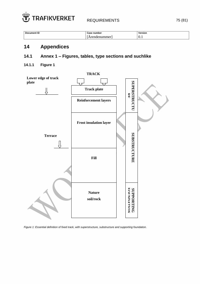
REQUIREMENTS 75 (81)
Document ID Case number Version
[Ärendenummer] 0.1
14 Appendices
14.1 Annex 1 – Figures, tables, type sections and suchlike
14.1.1 Figure 1
Figure 1: Essential definition of fixed track, with superstructure, substructure and supporting foundation.
Reinforcement layers
Fill
Track plate
SU
PE
RS
TR
UC
TU
RE
Frost insulation layer
TRACK
Nature
soil/rock
SU
BS
TR
UC
TU
RE
S
UP
PO
RT
ING
FO
UN
DA
TIO
N
Terrace
surface
Lower edge of track
plate
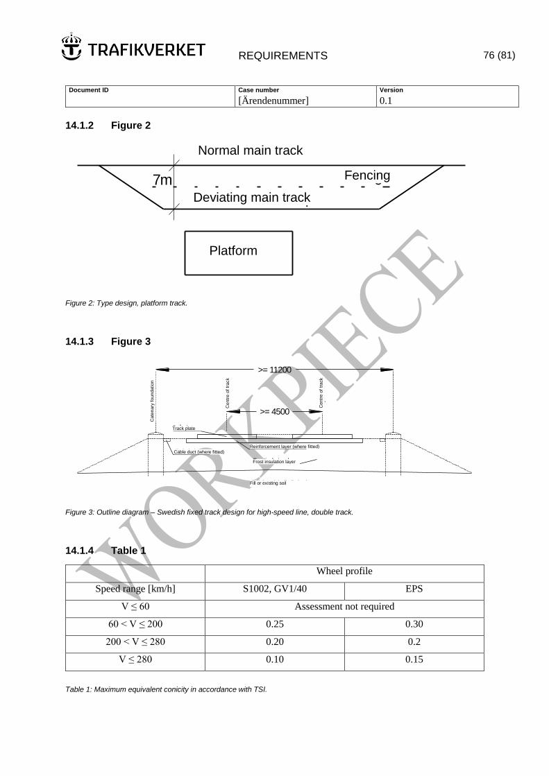
REQUIREMENTS 76 (81)
Document ID Case number Version
[Ärendenummer] 0.1
14.1.2 Figure 2
Normalhuvudspår
Avvikande huvudspår
Stängsel7m
Plattform
Figure 2: Type design, platform track.
14.1.3 Figure 3
ev förstärkningslager
Frostisoleringslager
>= 11200
>= 4500
Spårplatta
Spårm
itt
Spårm
itt
Konta
ktle
dnin
gsf
undam
ent
Ev kabelränna
Fyllning alt befintlig jord
Figure 3: Outline diagram – Swedish fixed track design for high-speed line, double track.
14.1.4 Table 1
Wheel profile
Speed range [km/h] S1002, GV1/40 EPS
V ≤ 60 Assessment not required
60 < V ≤ 200 0.25 0.30
200 < V ≤ 280 0.20 0.2
V ≤ 280 0.10 0.15
Table 1: Maximum equivalent conicity in accordance with TSI.
Normal main track
Deviating main track
Fencing
Platform
Track plate
Cable duct (where fitted) Reinforcement layer (where fitted)
Frost insulation layer
Fill or existing soil
Centr
e o
f tr
ack
Centr
e o
f tr
ack
Cate
nary
foundation
REQUIREMENTS 77 (81)
Document ID Case number Version
[Ärendenummer] 0.1
15 References
15.1 TSI
TSI Operation (2008/231/EC)
TSI Operation and traffic management (2010/640/EU)
TSI Operation and traffic management (2012/757/EU)
TSI Energy (2012-12-14)
TSI Infrastructure (2008/217/EC)
TSI LOC and PAS, TSI Rolling stock – Locomotives and passenger rolling stock (2011/291/EU)
TSI Safety in railway tunnels (2008/163/EC)
TSI Accessibility for persons with reduced mobility (2008/164/EC)
TSI Control command and signalling (2012/88/EU)
15.2 Other European standards and directives
SS-EN 14363:2005 Railway applications. Acceptance of running characteristics of railway vehicles –
Testing of running dynamics and stationary tests
SS-EN 1990, Basis of structural design (CEN EN 1990:2002 Sv)
SS-EN 1991-2, Actions on structures – Part 2: Traffic loads on bridges (CEN EN 1991-2:2003 Sv)
SS-EN 50119, Railway applications – Fixed installations – Electric traction overhead contact lines
SS-EN 50367, Railway applications – Current collection systems – Technical criteria for the
interaction between pantograph and overhead line (to achieve free access)
SS 137010, Concrete structures – Concrete cover
15.3 Swedish Transport Administration requirements, recommendations and AMA
AMA Civil Engineering Works 13, General description of materials and labour
TK Dewatering, Swedish Transport Administration technical requirements for dewatering
TR Dewatering, Swedish Transport Administration technical recommendations for dewatering
MB 310 Dewatering-related dimensioning and design
TRVK Bridge 11, Swedish Transport Administration technical requirements for bridges (TRV publ.
no. 2011:085)
TRVR Bridge 11, Swedish Transport Administration technical recommendations for bridges (TRV
publ. no. 2011:086)
TRVK Tunnel 11, Swedish Transport Administration technical requirements for tunnels (TRV publ.
no. 2011:087)
REQUIREMENTS 78 (81)
Document ID Case number Version
[Ärendenummer] 0.1
TRVR Tunnel 11, Swedish Transport Administration technical recommendations for tunnels (TRV
publ. no. 2011:088)
TK Geo 13, Swedish Transport Administration technical requirements for geostructures
TK Geo 11, Swedish Transport Administration technical requirements and recommendations for
construction and improvement of geostructures (TRV publ. no. 2011:047)
BVS 543.14320, "Direct current systems for telecommunications and signal installations"
BVS 1543.11601, "Power supply installations – Autotransformer systems – system description"
BVS 1543.14000, "Electric power installations – Ground and building requirements for converter
stations with static converters"
BVS 1543.14310, "Electric power installations – DC systems for electric power installations"
BVS 1543.14320, "Direct current systems for telecommunications and signal installations"
BVS 1543.17000, "Electric power installations – Converters for line power supply"
BVS 1545.10001, "Telecommunications systems – basic requirements for the Swedish Rail
Administration's telecommunications transmission network"
BVS 1545.16002, "Local connections to Gemini"
BVS 1586.20, "Track superstructure – Infrastructure profiles Requirements for free space at the
trackside
BVS 1586.26, "Track superstructure – Platforms, Geometric requirements for construction and
conversion"
TDOK 2013:0347, "Track superstructure – Track location requirements for construction and
maintenance"
TDOK 2013:0664, "Track superstructure – Jointless track, requirements for construction and
maintenance"
TDOK 2014:0075, "Track superstructure – Track geometry Requirements for track geometry during
construction, reinvestment/upgrade, maintenance and operation
15.4 Swedish Transport Administration publications and reports
Swedish Transport Administration, 2011. Railway for 320 km/h, Technical system standard – Track
location. (Project report 110115107, 2011-02-18)
High-speed tracks and expansion of existing main lines Stockholm-Gothenburg/Malmö, Swedish
Transport Administration background report, Lennart Lennefors (2012)
Swedish Transport Administration publication 2012:179 - about fauna passages, gates/bridges for
wildlife and ecoducts. (TRV publ. no. 2012:179)
Swedish Transport Administration publication 2012:181 - about fauna passages, gates/bridges for
wildlife and ecoducts. (TRV publ. no. 2012:181)
REQUIREMENTS 79 (81)
Document ID Case number Version
[Ärendenummer] 0.1
15.5 Laws and documents from other authorities
High voltage regulations, Swedish National Electrical Safety Board (ELSÄK-FS 2008:1)
15.6 Other railway administrations
Deutsche Bahn, 2002. Requirements Catalog for the Construction of the Permanent Way. DB Netz
AG/DB Systemtechnik, 4th Edition, (08/01/2002)
Deutsche Bahn, 2012. Richtlinie 804 – Eisenbahnbrücken (und sonstige Ingenieurbauwerke), bauen
und instand halten [Guideline 804 – Railway bridges (and other civil engineering works), construction
and maintenance]. DB Netz AG, (21/12/2012)
prEN 16432-1:2014 (E), Railway applications – Ballastless track systems – Part 1: General
requirements. (CEN/TC 256)
prEN 16432-2:2014 (E), Railway applications – Ballastless track systems – Part 2: Subsystems and
components. (CEN/TC 256)
15.7 Other
UIC report: "Maintenance of high speed lines"
Concrete Calendar 2000 – BK2
REQUIREMENTS 80 (81)
Document ID Case number Version
[Ärendenummer] 0.1
16 Change log
Established version Document date Change Name
0.9 12/02/2014
0.91 17/03/2014 Editorial changes. Text
added in section
8.11.2.9.
Karlsson, Robert,
UHau konsult
0.92 26/03/2014 Editorial changes. Text
deleted from sections
6.6.2.2 and 7.7.2. Text
amended in section
7.2.2.2.
Karlsson, Robert,
UHau konsult
0.93 22/05/2014 Text added in section
7.2.2.1.
Karlsson, Robert,
UHau konsult
0.94 03/06/2014 Editorial changes. Text
added in sections 7.1,
7.4.1, 8.1, 8.2.1, 8.2.2,
8.2.2.1, 8.2.2.2,
8.2.2.3, 8.2.2.4,
8.2.2.5, 8.7.2, 8.11.2,
8.11.2.1, 8.11.3,
8.11.3.1, 8.11.3.2,
8.11.3.3, 8.11.3.4,
8.11.3.5, 8.11.3.6,
8.11.3.7, 8.11.3.8,
8.11.3.9, 8.11.3.10,
8.11.3.11, 8.11.4,
8.11.4.1, 8.11.4.2,
8.11.5, 8.11.5.1,
8.11.5.2, 9.1, 9.2, 9.3,
9.4, 9.6, 9.7, 9.7.1, 9.8,
9.9, 9.10, 9.12, 9.13,
10.1, 10.7.1, 11.1,
11.2, 11.3, 11.4, 11.5,
11.6, 11.7, 11.7.1,
11.8, 11.9, 11.10,
11.11, 11.12, 11.13,
11.14, 12.1, 12.7.2,
12.7.3, 13.1 and 15.3.
Text deleted from
sections 7.1, 8.6.1, 8.7,
8.7.2, 9.1, 9.6, 9.7,
9.10, 10.1, 10.5, 10.7,
10.10, 11.1, 11.2, 11.3,
11.4, 11.5, 11.6, 11.7,
11.8, 11.11, 11.13,
11.14, 12.7.2 and 15.6.
Karlsson, Robert,
UHau konsult
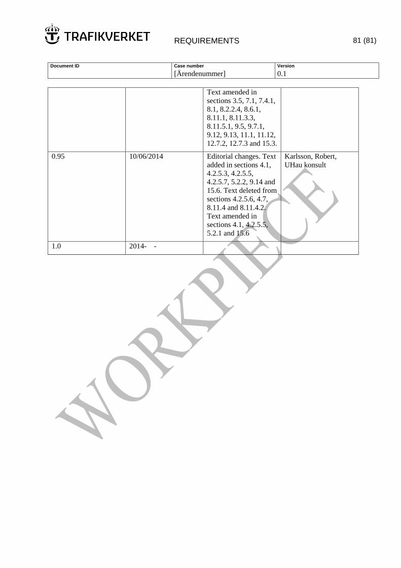
REQUIREMENTS 81 (81)
Document ID Case number Version
[Ärendenummer] 0.1
Text amended in
sections 3.5, 7.1, 7.4.1,
8.1, 8.2.2.4, 8.6.1,
8.11.1, 8.11.3.3,
8.11.5.1, 9.5, 9.7.1,
9.12, 9.13, 11.1, 11.12,
12.7.2, 12.7.3 and 15.3.
0.95 10/06/2014 Editorial changes. Text
added in sections 4.1,
4.2.5.3, 4.2.5.5,
4.2.5.7, 5.2.2, 9.14 and
15.6. Text deleted from
sections 4.2.5.6, 4.7,
8.11.4 and 8.11.4.2.
Text amended in
sections 4.1, 4.2.5.5,
5.2.1 and 15.6
Karlsson, Robert,
UHau konsult
1.0 2014-06-