Embed Size (px)
Citation preview
Technical Supplement
OEMControls
3120344
March 1, 2008

REVISION LOG
June 30, 1990 - Original Issue Of Manual
November 15, 2001 - Revised Manual
March 15, 2003 - Revised Manual
March 1, 2008 - Revised Manual
3120344 OEM Controls A
REVISION LOG
B OEM Controls 3120344
TABLE OF CONTENTS
SECTION NO. TITLE PAGE NO.SECTION 1 - CHARACTERISTICS. . . . . . . . . . . . . . . . . . . . . . . . . . . . . . . . . . . . . . . . . . . . . . . . . .1-1
USAGE . . . . . . . . . . . . . . . . . . . . . . . . . . . . . . . . . . . . . . . . . . . . . . . . . . . . . . . . . . . . . .1-1FEATURES . . . . . . . . . . . . . . . . . . . . . . . . . . . . . . . . . . . . . . . . . . . . . . . . . . . . . . . . . . .1-1THEORY OF OPERATION . . . . . . . . . . . . . . . . . . . . . . . . . . . . . . . . . . . . . . . . . . . . . . .1-1IDENTIFICATION . . . . . . . . . . . . . . . . . . . . . . . . . . . . . . . . . . . . . . . . . . . . . . . . . . . . . . .1-2
SECTION 2 - ADJUSTMENTS . . . . . . . . . . . . . . . . . . . . . . . . . . . . . . . . . . . . . . . . . . . . . . . . . . . . . .2-1
2-1 CONTROLLER ADJUSTMENT (ADJUSTED BY CIRCUIT BOARD WITH TRIMPOTS) .2-12-2 CONTROLLER ADJUSTMENT (ADJUSTED BY MODULE AND ANALYZER) . . . . . . . .2-22-3 CONTROLLER SEALING INSTRUCTIONS . . . . . . . . . . . . . . . . . . . . . . . . . . . . . . . . . . .2-22-4 SWITCH ADJUSTMENT PROCEDURE . . . . . . . . . . . . . . . . . . . . . . . . . . . . . . . . . . . . .2-2
SECTION 3 - TROUBLESHOOTING . . . . . . . . . . . . . . . . . . . . . . . . . . . . . . . . . . . . . . . . . . . . . . . .3-1
3-1 PRINTED CIRCUIT BOARD TERMINAL BOARD CONNECTIONS . . . . . . . . . . . . . . . . .3-13-2 TESTING PROCEDURES . . . . . . . . . . . . . . . . . . . . . . . . . . . . . . . . . . . . . . . . . . . . . . . .3-13-3 TROUBLESHOOTING PROCEDURES . . . . . . . . . . . . . . . . . . . . . . . . . . . . . . . . . . . . . .3-23-4 1600235 CONTROLLER . . . . . . . . . . . . . . . . . . . . . . . . . . . . . . . . . . . . . . . . . . . . . . . . .3-33-5 1600239 CONTROLLER . . . . . . . . . . . . . . . . . . . . . . . . . . . . . . . . . . . . . . . . . . . . . . . . .3-33-6 1600242 CONTROLLER . . . . . . . . . . . . . . . . . . . . . . . . . . . . . . . . . . . . . . . . . . . . . . . . .3-33-7 1600245 CONTROLLER . . . . . . . . . . . . . . . . . . . . . . . . . . . . . . . . . . . . . . . . . . . . . . . . .3-43-8 1600257 CONTROLLER . . . . . . . . . . . . . . . . . . . . . . . . . . . . . . . . . . . . . . . . . . . . . . . . .3-43-9 1600263 CONTROLLER . . . . . . . . . . . . . . . . . . . . . . . . . . . . . . . . . . . . . . . . . . . . . . . . .3-43-10 1600270 CONTROLLER . . . . . . . . . . . . . . . . . . . . . . . . . . . . . . . . . . . . . . . . . . . . . . . . .3-43-11 1600271 CONTROLLER . . . . . . . . . . . . . . . . . . . . . . . . . . . . . . . . . . . . . . . . . . . . . . . . .3-53-12 1600272 CONTROLLER . . . . . . . . . . . . . . . . . . . . . . . . . . . . . . . . . . . . . . . . . . . . . . . . .3-53-13 1600273 CONTROLLER . . . . . . . . . . . . . . . . . . . . . . . . . . . . . . . . . . . . . . . . . . . . . . . . .3-53-14 1600274 CONTROLLER . . . . . . . . . . . . . . . . . . . . . . . . . . . . . . . . . . . . . . . . . . . . . . . . .3-53-15 1600278 CONTROLLER . . . . . . . . . . . . . . . . . . . . . . . . . . . . . . . . . . . . . . . . . . . . . . . . .3-63-16 1600283 CONTROLLER . . . . . . . . . . . . . . . . . . . . . . . . . . . . . . . . . . . . . . . . . . . . . . . . .3-73-17 1600284 CONTROLLER . . . . . . . . . . . . . . . . . . . . . . . . . . . . . . . . . . . . . . . . . . . . . . . . .3-73-18 1600287 CONTROLLER . . . . . . . . . . . . . . . . . . . . . . . . . . . . . . . . . . . . . . . . . . . . . . . . .3-73-19 1600288 CONTROLLER . . . . . . . . . . . . . . . . . . . . . . . . . . . . . . . . . . . . . . . . . . . . . . . . .3-83-20 1600306 CONTROLLER . . . . . . . . . . . . . . . . . . . . . . . . . . . . . . . . . . . . . . . . . . . . . . . . .3-93-21 1600317 CONTROLLER . . . . . . . . . . . . . . . . . . . . . . . . . . . . . . . . . . . . . . . . . . . . . . . . .3-103-22 1600318 CONTROLLER . . . . . . . . . . . . . . . . . . . . . . . . . . . . . . . . . . . . . . . . . . . . . . . . .3-103-23 1600330 CONTROLLER . . . . . . . . . . . . . . . . . . . . . . . . . . . . . . . . . . . . . . . . . . . . . . . . .3-103-24 1600334 CONTROLLER . . . . . . . . . . . . . . . . . . . . . . . . . . . . . . . . . . . . . . . . . . . . . . . . .3-10
SECTION 4 - REPLACEMENT PARTS . . . . . . . . . . . . . . . . . . . . . . . . . . . . . . . . . . . . . . . . . . . . . .4-1
4-1 CONTROLLER WITH SINGLE GATE & NO ROCKER SWITCH . . . . . . . . . . . . . . . . . . . . . . .4-24-2 CONTROLLER WITH SINGLE GATE & ROCKER SWITCH . . . . . . . . . . . . . . . . . . . . . . . . . .4-64-3 CONTROLLER WITH ROUND GATE & LIFT CAP . . . . . . . . . . . . . . . . . . . . . . . . . . . . . . . .4-124-4 CONTROLLER WITH ROUND GATE & TRIGGER GRIP . . . . . . . . . . . . . . . . . . . . . . . . . . . .4-184-5 SPEED CONTROLLER WITH SNAIL/CREEP SPEED SWITCH . . . . . . . . . . . . . . . . . . . . . .4-20
3120344 OEM Controls i
TABLE OF CONTENTS
SECTION NO. TITLE PAGE NO.
ii OEM Controls 3120344
3120344
SECTION 1 CHARACTERISTICS
SECTION
1
CHARACTERISTICS
OEM CONTROLLER TECHNICAL SUPPLEMENT
USAGE
OEM Controllers have been used on the various JLG products either as standard or optional equipment. OEM Controllers were offered as standard equipment on various “A,” “AJ,” “AJP,” “ic,” “E,” “M,” “S,” “SC,” “SCJ,” “SJ” & “SX” Boom Lift Models & “E” Scissor Lifts and as optional equipment on “H,” “HA,” “HT” & “HX” Boom Lift Models.
FEATURES
The OEM Controller converts manual input into proportional electrical output signals for the commanding propor-tional flow control valves. The OEM Controller is a seal unit and can withstand hostile and rugged outdoor weather conditions. The controller handle/stem enters the housing through a sealed entrance, reducing the possi-bilities of water entering the housing.
Adjustment of these controllers is done through trimpots on a circuit board (which may be attached to the control-ler or separately mounted in the platform console box) or through a handheld analyzer which adjusts the person-ality setting in an external module.
Drive, Steer, Lift and Swing Controllers (All Controllers except 1600272) These OEM Controllers incorporate a mechanical safety lock whereby the operator must make an additional motion to unlock the control handle prior to operation.This feature eliminates the possibility of the control being accidentially energized while in the neutral position. The control handle is spring loaded, and will automatically return to neutral-off position should should the operator accidentically lose grip of the handle. This feature gives the operator positive control of the machine at all times, requiring the operator to hold the control handle during the duration of the desired function.
Speed Controller (1600272 Controller Only) This OEM Controller features a creep/snail function.
THEORY OF OPERATION
PWM Output (Pulse Width Modulation)Because of the mass of the spool, shifting it a very small distance would be very difficult to do without overshoot-ing the mark. This overshoot is called hystersis and makes precise control of the function very difficult. PWM out-put provides a pulsed current to the spool which actually vibrates the spool so that it is never at rest and very easy to shift. As you move the handle/stem, the electronics change the time period the pulse is on within that cycle. As you move the handle away from center, the on time period or width of the cycle pulse will increase and as you you move the handle back towards the center, the pulse will decrease. The percentage of on time to off time of the PWM signal is called the Duty Cycle, if it is on for 80% it is called an 80% duty cycle.
Current Regulated OutputThis controller is also current regulated. Ohms Law dictates that current always equals voltage divided by resis-tance. If the supply voltage or the coil resistance should change, Ohms Law dictates that the output current must also change which affects the speed of the function accordingly. Current regulated output feature senses a change in voltage or resistance in the circuit and adjusts the duty cycle of the PWM signal so that the output current remains a constant current. Because the current is constant and the resistance is machine dependant, the duty cycle will vary in an attempt to supply the supply the required level of output. This feature ensures that the func-tion speed the operator chooses to select always remains the same, within the limits of Ohms Law.
IRS (Integrated Ramp System)OEM Controllers are calibrated to provide a maximum ramp time of 2 seconds. This feature limits the rate of change of the output, eliminating jerky response associated with sudden handle movements. Any change in the handle position will result in a smooth change in function speed. The 2 seconds is measured between the Thresh-old and HI or LO Range setting.
OEM Controls 1-1
SECTION 1 CHARACTERISTICSSECTION
1
CHARACTERISTICS
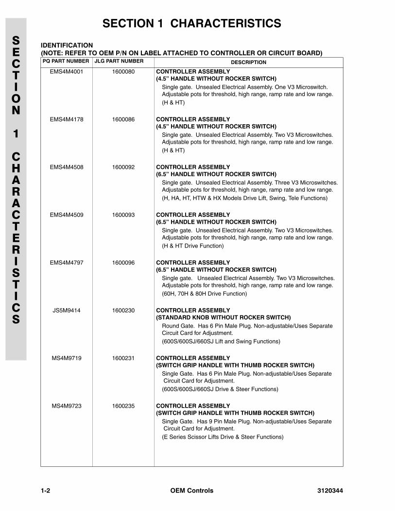
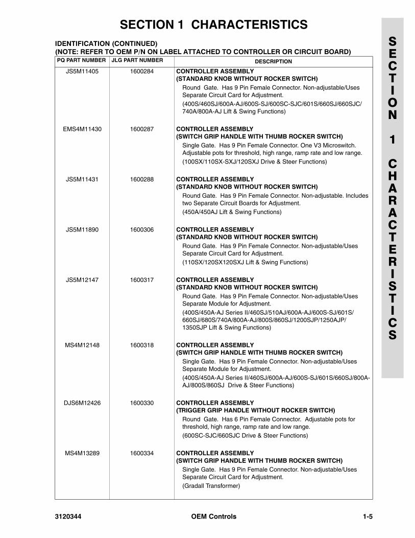
IDENTIFICATION (NOTE: REFER TO OEM P/N ON LABEL ATTACHED TO CONTROLLER OR CIRCUIT BOARD)PQ PART NUMBER JLG PART NUMBER DESCRIPTION
EMS4M4001 1600080 CONTROLLER ASSEMBLY(4.5” HANDLE WITHOUT ROCKER SWITCH)
Single gate. Unsealed Electrical Assembly. One V3 Microswitch. Adjustable pots for threshold, high range, ramp rate and low range.
(H & HT)
EMS4M4178 1600086 CONTROLLER ASSEMBLY(4.5” HANDLE WITHOUT ROCKER SWITCH)
Single gate. Unsealed Electrical Assembly. Two V3 Microswitches. Adjustable pots for threshold, high range, ramp rate and low range.
(H & HT)
EMS4M4508 1600092 CONTROLLER ASSEMBLY(6.5” HANDLE WITHOUT ROCKER SWITCH)
Single gate. Unsealed Electrical Assembly. Three V3 Microswitches. Adjustable pots for threshold, high range, ramp rate and low range.
(H, HA, HT, HTW & HX Models Drive Lift, Swing, Tele Functions)
EMS4M4509 1600093 CONTROLLER ASSEMBLY(6.5” HANDLE WITHOUT ROCKER SWITCH)
Single gate. Unsealed Electrical Assembly. Two V3 Microswitches. Adjustable pots for threshold, high range, ramp rate and low range. (H & HT Drive Function)
EMS4M4797 1600096 CONTROLLER ASSEMBLY(6.5” HANDLE WITHOUT ROCKER SWITCH)
Single gate. Unsealed Electrical Assembly. Two V3 Microswitches. Adjustable pots for threshold, high range, ramp rate and low range.
(60H, 70H & 80H Drive Function)
JS5M9414 1600230 CONTROLLER ASSEMBLY(STANDARD KNOB WITHOUT ROCKER SWITCH)
Round Gate. Has 6 Pin Male Plug. Non-adjustable/Uses Separate Circuit Card for Adjustment.
(600S/600SJ/660SJ Lift and Swing Functions)
MS4M9719 1600231 CONTROLLER ASSEMBLY(SWITCH GRIP HANDLE WITH THUMB ROCKER SWITCH)
Single Gate. Has 6 Pin Male Plug. Non-adjustable/Uses Separate Circuit Card for Adjustment. (600S/600SJ/660SJ Drive & Steer Functions)
MS4M9723 1600235 CONTROLLER ASSEMBLY(SWITCH GRIP HANDLE WITH THUMB ROCKER SWITCH)
Single Gate. Has 9 Pin Male Plug. Non-adjustable/Uses Separate Circuit Card for Adjustment.
(E Series Scissor Lifts Drive & Steer Functions)
1-2 OEM Controls 3120344
SECTION 1 CHARACTERISTICSSECTION
1
CHARACTERISTICS
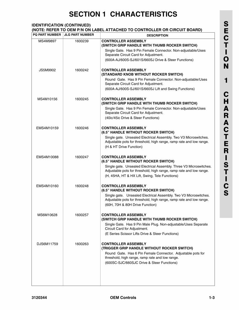
MS4M9897 1600239 CONTROLLER ASSEMBLY(SWITCH GRIP HANDLE WITH THUMB ROCKER SWITCH)
Single Gate. Has 9 Pin Female Connector. Non-adjustable/Uses Separate Circuit Card for Adjustment.
(600A-AJ/600S-SJ/601S/660SJ Drive & Steer Functions)
JS5M9902 1600242 CONTROLLER ASSEMBLY(STANDARD KNOB WITHOUT ROCKER SWITCH)
Round Gate. Has 9 Pin Female Connector. Non-adjustable/Uses Separate Circuit Card for Adjustment.
(600A-AJ/600S-SJ/601S/660SJ Lift and Swing Functions)
MS4M10156 1600245 CONTROLLER ASSEMBLY(SWITCH GRIP HANDLE WITH THUMB ROCKER SWITCH)
Single Gate. Has 9 Pin Female Connector. Non-adjustable/Uses Separate Circuit Card for Adjustment.
(40ic/45ic Drive & Steer Functions)
EMS4M10159 1600246 CONTROLLER ASSEMBLY(6.5” HANDLE WITHOUT ROCKER SWITCH)
Single gate. Unsealed Electrical Assembly. Two V3 Microswitches. Adjustable pots for threshold, high range, ramp rate and low range. (H & HT Drive Function)
EMS4M10088 1600247 CONTROLLER ASSEMBLY(6.5” HANDLE WITHOUT ROCKER SWITCH)
Single gate. Unsealed Electrical Assembly. Three V3 Microswitches. Adjustable pots for threshold, high range, ramp rate and low range.
(H, 45HA, HT & HX Lift, Swing, Tele Functions)
EMS4M10160 1600248 CONTROLLER ASSEMBLY(6.5” HANDLE WITHOUT ROCKER SWITCH)
Single gate. Unsealed Electrical Assembly. Two V3 Microswitches. Adjustable pots for threshold, high range, ramp rate and low range.
(60H, 70H & 80H Drive Function)
MS6M10628 1600257 CONTROLLER ASSEMBLY(SWITCH GRIP HANDLE WITH THUMB ROCKER SWITCH)
Single Gate. Has 9 Pin Male Plug. Non-adjustable/Uses Separate Circuit Card for Adjustment. (E Series Scissor Lifts Drive & Steer Functions)
DJS6M11759 1600263 CONTROLLER ASSEMBLY(TRIGGER GRIP HANDLE WITHOUT ROCKER SWITCH)
Round Gate. Has 6 Pin Female Connector. Adjustable pots for threshold, high range, ramp rate and low range.
(600SC-SJC/660SJC Drive & Steer Functions)
IDENTIFICATION (CONTINUED) (NOTE: REFER TO OEM P/N ON LABEL ATTACHED TO CONTROLLER OR CIRCUIT BOARD)PQ PART NUMBER JLG PART NUMBER DESCRIPTION
3120344 OEM Controls 1-3
SECTION 1 CHARACTERISTICSSECTION
1
CHARACTERISTICS
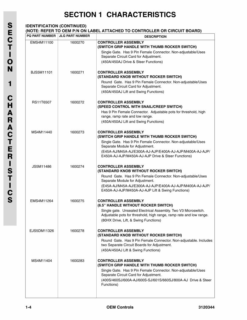
EMS4M11100 1600270 CONTROLLER ASSEMBLY(SWITCH GRIP HANDLE WITH THUMB ROCKER SWITCH)
Single Gate. Has 9 Pin Female Connector. Non-adjustable/Uses Separate Circuit Card for Adjustment.
(450A/450AJ Drive & Steer Functions)
BJS5M11101 1600271 CONTROLLER ASSEMBLY(STANDARD KNOB WITHOUT ROCKER SWITCH)
Round Gate. Has 9 Pin Female Connector. Non-adjustable/Uses Separate Circuit Card for Adjustment.
(450A/450AJ Lift and Swing Functions)
RS11T6507 1600272 CONTROLLER ASSEMBLY(SPEED CONTROL WITH SNAIL/CREEP SWITCH)
Has 9 Pin Female Connector. Adjustable pots for threshold, high range, ramp rate and low range.
(450A/450AJ Lift and Swing Functions)
MS4M11440 1600273 CONTROLLER ASSEMBLY(SWITCH GRIP HANDLE WITH THUMB ROCKER SWITCH)
Single Gate. Has 9 Pin Female Connector. Non-adjustable/Uses Separate Module for Adjustment. (E45A-AJ/M45A-AJ/E300A-AJ-AJP/E400A-AJ-AJP/M400A-AJ-AJP/E450A-AJ-AJP/M450A-AJ-AJP Drive & Steer Functions)
JS5M11486 1600274 CONTROLLER ASSEMBLY(STANDARD KNOB WITHOUT ROCKER SWITCH)
Round Gate. Has 9 Pin Female Connector. Non-adjustable/Uses Separate Module for Adjustment.
(E45A-AJ/M45A-AJ/E300A-AJ-AJP/E400A-AJ-AJP/M400A-AJ-AJP/E450A-AJ-AJP/M450A-AJ-AJP Lift & Swing Functions)
EMS4M11264 1600275 CONTROLLER ASSEMBLY(6.5” HANDLE WITHOUT ROCKER SWITCH)
Single gate. Unsealed Electrical Assembly. Two V3 Microswitch. Adjustable pots for threshold, high range, ramp rate and low range.
(80HX Drive, Lift, & Swing Functions)
EJS5DM11326 1600278 CONTROLLER ASSEMBLY(STANDARD KNOB WITHOUT ROCKER SWITCH)
Round Gate. Has 9 Pin Female Connector. Non-adjustable. Includes two Separate Circuit Boards for Adjustment.
(450A/450AJ Lift & Swing Functions)
MS4M11404 1600283 CONTROLLER ASSEMBLY(SWITCH GRIP HANDLE WITH THUMB ROCKER SWITCH)
Single Gate. Has 9 Pin Female Connector. Non-adjustable/Uses Separate Circuit Card for Adjustment.
(400S/460SJ/600A-AJ/600S-SJ/601S/660SJ/800A-AJ Drive & Steer Functions)
IDENTIFICATION (CONTINUED) (NOTE: REFER TO OEM P/N ON LABEL ATTACHED TO CONTROLLER OR CIRCUIT BOARD)PQ PART NUMBER JLG PART NUMBER DESCRIPTION
1-4 OEM Controls 3120344
SECTION 1 CHARACTERISTICSSECTION
1
CHARACTERISTICS
JS5M11405 1600284 CONTROLLER ASSEMBLY(STANDARD KNOB WITHOUT ROCKER SWITCH)
Round Gate. Has 9 Pin Female Connector. Non-adjustable/Uses Separate Circuit Card for Adjustment.
(400S/460SJ/600A-AJ/600S-SJ/600SC-SJC/601S/660SJ/660SJC/740A/800A-AJ Lift & Swing Functions)
EMS4M11430 1600287 CONTROLLER ASSEMBLY(SWITCH GRIP HANDLE WITH THUMB ROCKER SWITCH)
Single Gate. Has 9 Pin Female Connector. One V3 Microswitch. Adjustable pots for threshold, high range, ramp rate and low range.
(100SX/110SX-SXJ/120SXJ Drive & Steer Functions)
JS5M11431 1600288 CONTROLLER ASSEMBLY(STANDARD KNOB WITHOUT ROCKER SWITCH)
Round Gate. Has 9 Pin Female Connector. Non-adjustable. Includes two Separate Circuit Boards for Adjustment.(450A/450AJ Lift & Swing Functions)
JS5M11890 1600306 CONTROLLER ASSEMBLY(STANDARD KNOB WITHOUT ROCKER SWITCH)
Round Gate. Has 9 Pin Female Connector. Non-adjustable/Uses Separate Circuit Card for Adjustment.
(110SX/120SX120SXJ Lift & Swing Functions)
JS5M12147 1600317 CONTROLLER ASSEMBLY(STANDARD KNOB WITHOUT ROCKER SWITCH)
Round Gate. Has 9 Pin Female Connector. Non-adjustable/Uses Separate Module for Adjustment.
(400S/450A-AJ Series II/460SJ/510AJ/600A-AJ/600S-SJ/601S/660SJ/680S/740A/800A-AJ/800S/860SJ/1200SJP/1250AJP/1350SJP Lift & Swing Functions)
MS4M12148 1600318 CONTROLLER ASSEMBLY(SWITCH GRIP HANDLE WITH THUMB ROCKER SWITCH)
Single Gate. Has 9 Pin Female Connector. Non-adjustable/Uses Separate Module for Adjustment.
(400S/450A-AJ Series II/460SJ/600A-AJ/600S-SJ/601S/660SJ/800A-AJ/800S/860SJ Drive & Steer Functions)
DJS6M12426 1600330 CONTROLLER ASSEMBLY(TRIGGER GRIP HANDLE WITHOUT ROCKER SWITCH)
Round Gate. Has 6 Pin Female Connector. Adjustable pots for threshold, high range, ramp rate and low range.
(600SC-SJC/660SJC Drive & Steer Functions)
MS4M13289 1600334 CONTROLLER ASSEMBLY(SWITCH GRIP HANDLE WITH THUMB ROCKER SWITCH)
Single Gate. Has 9 Pin Female Connector. Non-adjustable/Uses Separate Circuit Card for Adjustment. (Gradall Transformer)
IDENTIFICATION (CONTINUED) (NOTE: REFER TO OEM P/N ON LABEL ATTACHED TO CONTROLLER OR CIRCUIT BOARD)PQ PART NUMBER JLG PART NUMBER DESCRIPTION
3120344 OEM Controls 1-5
SECTION 1 CHARACTERISTICSSECTION
1
CHARACTERISTICS
THIS PAGE INTENTIONALLY LEFT BLANK
1-6 OEM Controls 3120344
SECTION 2 ADJUSTMENTS
SECTION
2
ADJUSTMENTS
2.1 1600080 ADJUSTMENT1600086 ADJUSTMENT1600092 ADJUSTMENT1600093 ADJUSTMENT1600096 ADJUSTMENT1600230 ADJUSTMENT1600231 ADJUSTMENT1600235 ADJUSTMENT1600239 ADJUSTMENT1600242 ADJUSTMENT1600245 ADJUSTMENT1600246 ADJUSTMENT1600247 ADJUSTMENT1600248 ADJUSTMENT1600257 ADJUSTMENT1600263 ADJUSTMENT1600270 ADJUSTMENT1600271 ADJUSTMENT1600272 ADJUSTMENT1600275 ADJUSTMENT1600278 ADJUSTMENT1600283 ADJUSTMENT1600284 ADJUSTMENT1600287 ADJUSTMENT1600288 ADJUSTMENT1600306 ADJUSTMENT1600330 ADJUSTMENT
NOTE: Trimpots may be on controller or on a separate cir-cuit board located in the platform console box.
NOTE: Controller trimpot adjustments are necessary afterinstallation of the new or reworked electrical assem-bly (printed circuit board), valve servo section orother electrical circuit components. When adjustingany controller seek to match the valves electricaloperating range by setting the controller trimpots.
LED’s on the circuit board show if the controller works.The "A" terminal LED lights when the handle is moved inthe "A" direction. "B" terminal LED lights when moved inthe "B" direction.
All adjustments must be done in the following order:Threshold, Hi Range, Lo Range, IRS. (See Figure 2-1)
The following instructions show how to set up the control-ler by observing function response:
NOTE: Before proceeding, position creep switch to "OFF,"Ignition "ON," and depress Footswitch.
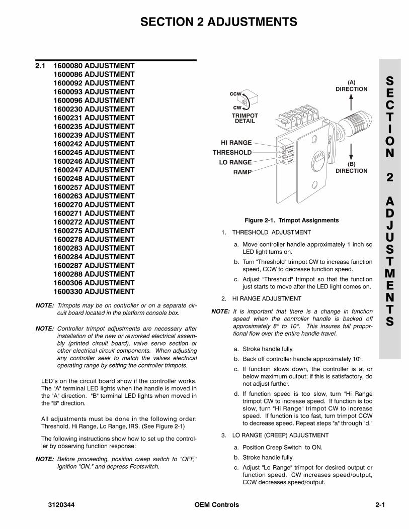
Figure 2-1. Trimpot Assignments
1. THRESHOLD ADJUSTMENT
a. Move controller handle approximately 1 inch soLED light turns on.
b. Turn "Threshold" trimpot CW to increase functionspeed, CCW to decrease function speed.
c. Adjust "Threshold" trimpot so that the functionjust starts to move after the LED light comes on.
2. HI RANGE ADJUSTMENT
NOTE: It is important that there is a change in functionspeed when the controller handle is backed offapproximately 8° to 10°. This insures full propor-tional flow over the entire handle travel.
a. Stroke handle fully.
b. Back off controller handle approximately 10°.
c. If function slows down, the controller is at orbelow maximum output; if this is satisfactory, donot adjust further.
d. If function speed is too slow, turn "Hi Rangetrimpot CW to increase speed. If function is tooslow, turn "Hi Range" trimpot CW to increasespeed. If function is too fast, turn trimpot CCWto decrease speed. Repeat steps "a" through "d."
3. LO RANGE (CREEP) ADJUSTMENT
a. Position Creep Switch to ON.
b. Stroke handle fully.
c. Adjust "Lo Range" trimpot for desired output orfunction speed. CW increases speed/output,CCW decreases speed/output.
3120344 OEM Controls 2-1
2-2
SECTION 2 ADJUSTMENTS
SECTION
2
ADJUSTMENTS
4. IRS (RAMP RATE) ADJUSTMENT
a. Turning the "Ramp Rate" trimpot CW increasesthe time it takes to turn ON or OFF when thehandle is moved; CCW decreases the time.
b. Trimpot has wide adjustment range, therefore itwill be necessary to make 2 to 3 turns to noticea difference in function response.
WHEN THE CONTROLLER HANDLE IS RETURNED TO CENTERAND THE CONTROLLER OUTPUT RAMPS TO (0), THE POWER ISDISCONNECTED TO THE BOARD.
NOTE: Disconnect wires from A and B terminals of mal-functioning controller and connect to same termi-nals of another controller on console known to beworking properly. Note wire colors, DO NOTCROSS, as function direction will reverse. If mal-function continues, the controller is okay, and theproblem is most likely at the control valve.
2.2 1600273 ADJUSTMENT1600274 ADJUSTMENT1600317 ADJUSTMENT1600318 ADJUSTMENT
NOTE: Refer to Service and Maintenance Manual of thespecific model machine to be serviced for the cor-rect calibrations required.
2.3 CONTROLLER SEALING INSTRUCTION.
TO ENSURE LONG TERM SAFE OPERATION OF CONTROLLER,ELECTRICAL ASSEMBLY MUST BE PROPERLY ADJUSTED ANDSEALED WITH BONDING AGENT. USE LOCTITE SUPERBONDER #495 OR EQUIVALENT AS BONDING AGENT. APPLYBONDING AGENT AS SHOWN BELOW.
Apply small drop of bonding agent on potentiometer shaft and gear at one end of slot after null adjustment. The setscrewshould be tight prior to application (See Figure 2-1 Item 1).
NOTE: Excessive bonding agent at item 1 could work downshaft and cause seisure of the shaft to bushing. Becareful to confine the application to a small amountin this area.
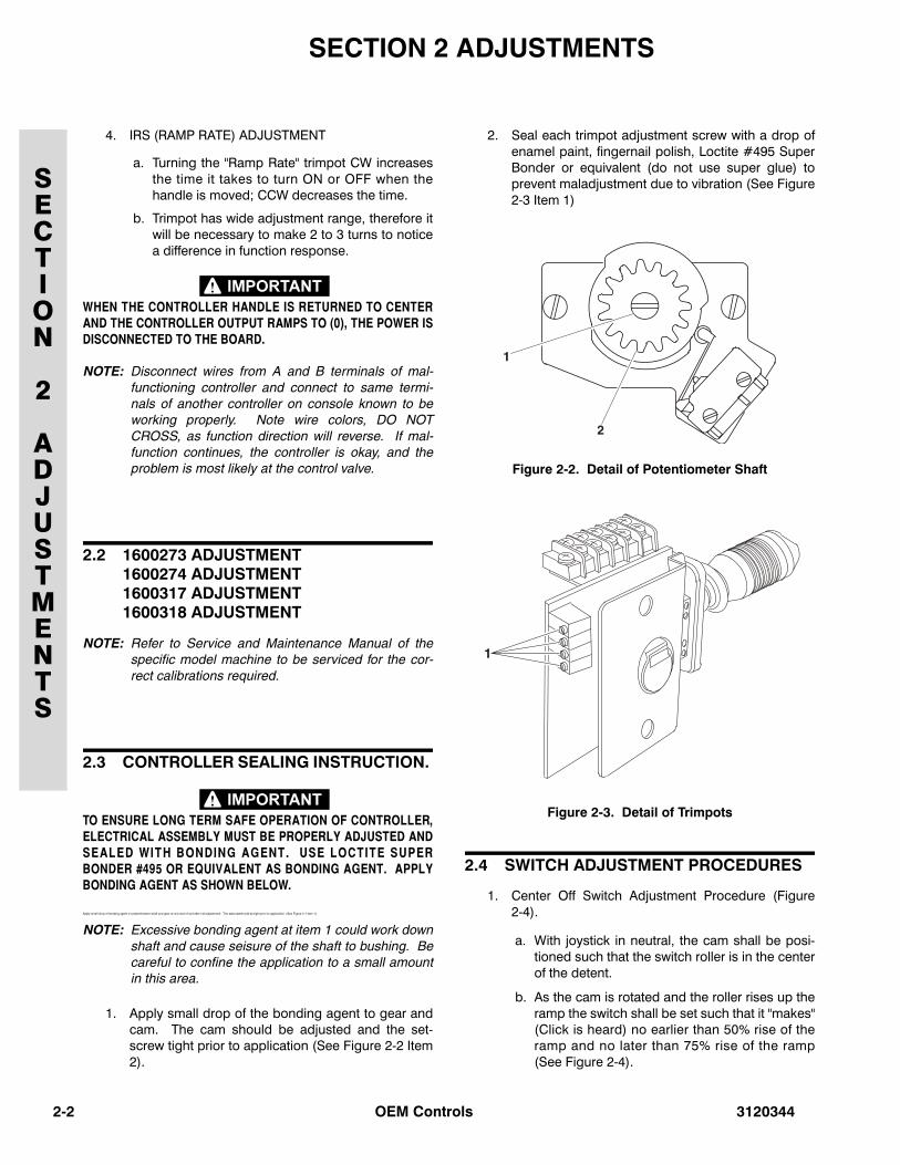
1. Apply small drop of the bonding agent to gear andcam. The cam should be adjusted and the set-screw tight prior to application (See Figure 2-2 Item2).
2. Seal each trimpot adjustment screw with a drop ofenamel paint, fingernail polish, Loctite #495 SuperBonder or equivalent (do not use super glue) toprevent maladjustment due to vibration (See Figure2-3 Item 1)
Figure 2-2. Detail of Potentiometer Shaft
Figure 2-3. Detail of Trimpots
2.4 SWITCH ADJUSTMENT PROCEDURES
1. Center Off Switch Adjustment Procedure (Figure2-4).
a. With joystick in neutral, the cam shall be posi-tioned such that the switch roller is in the centerof the detent.
b. As the cam is rotated and the roller rises up theramp the switch shall be set such that it "makes"(Click is heard) no earlier than 50% rise of theramp and no later than 75% rise of the ramp(See Figure 2-4).
OEM Controls 3120344
SECTION 2 ADJUSTMENTS
SECTION
2
ADJUSTMENTS
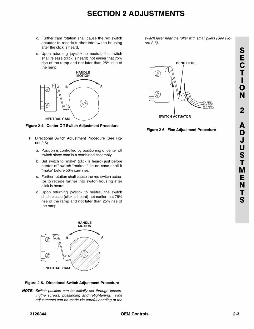
c. Further cam rotation shall cause the red switchactuator to recede further into switch housingafter the click is heard.
d. Upon returning joystick to neutral, the switchshall release (click is heard) not earlier that 75%rise of the ramp and not later than 25% rise ofthe ramp.
Figure 2-4. Center Off Switch Adjustment Procedure
1. Directional Switch Adjustment Procedure (See Fig-ure 2-5).
a. Position is controlled by positioning of center offswitch since cam is a combined assembly.
b. Set switch to "make" (click is heard) just beforecenter off switch "makes." In no case shall it"make" before 50% cam rise.
c. Further rotation shall cause the red switch actau-tor to recede further into switch housing afterclick is heard.
d. Upon returning joystick to neutral, the switchshall release (click is heard) not earlier that 75%rise of the ramp and not later than 25% rise ofthe ramp
Figure 2-5. Directional Switch Adjustment Procedure
NOTE: Switch position can be initially set through loosen-ingthe screws, positioning and retightening. Fineadjustments can be made via careful bending of the
switch lever near the roller with small pliers (See Fig-ure 2-6).
Figure 2-6. Fine Adjustment Procedure
3120344 OEM Controls 2-3
2-4
SECTION 2 ADJUSTMENTS
SECTION
2
ADJUSTMENTS
THIS PAGE INTENTIONALLY LEFT BLANK
OEM Controls 3120344
SECTION 3 TROUBLESHOOTING
SECTION
3
TROUBLESHOOTING
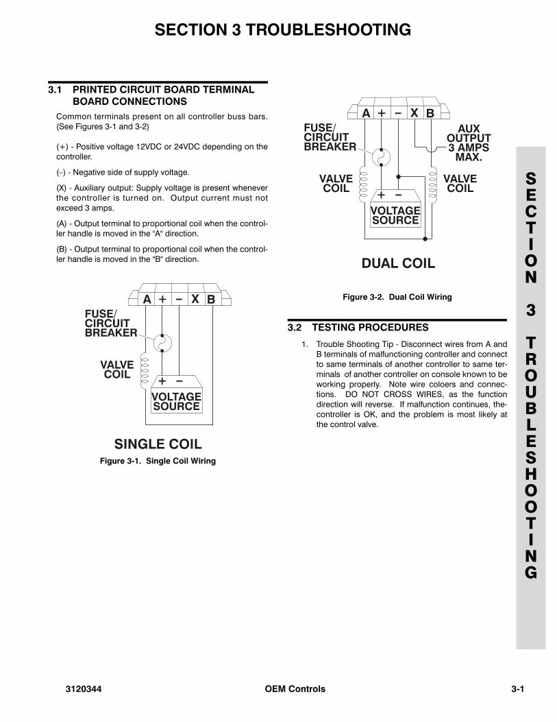
3.1 PRINTED CIRCUIT BOARD TERMINAL BOARD CONNECTIONS
Common terminals present on all controller buss bars.(See Figures 3-1 and 3-2)
(+) - Positive voltage 12VDC or 24VDC depending on thecontroller.
(–) - Negative side of supply voltage.
(X) - Auxiliary output: Supply voltage is present wheneverthe controller is turned on. Output current must notexceed 3 amps.
(A) - Output terminal to proportional coil when the control-ler handle is moved in the "A" direction.
(B) - Output terminal to proportional coil when the control-ler handle is moved in the "B" direction.
Figure 3-1. Single Coil Wiring
Figure 3-2. Dual Coil Wiring
3.2 TESTING PROCEDURES
1. Trouble Shooting Tip - Disconnect wires from A andB terminals of malfunctioning controller and connectto same terminals of another controller to same ter-minals of another controller on console known to beworking properly. Note wire coloers and connec-tions. DO NOT CROSS WIRES, as the functiondirection will reverse. If malfunction continues, the-controller is OK, and the problem is most likely atthe control valve.
3120344 OEM Controls 3-1
3-2
SECTION 3 TROUBLESHOOTING
SECTION
3
TROUBLESHOOTING
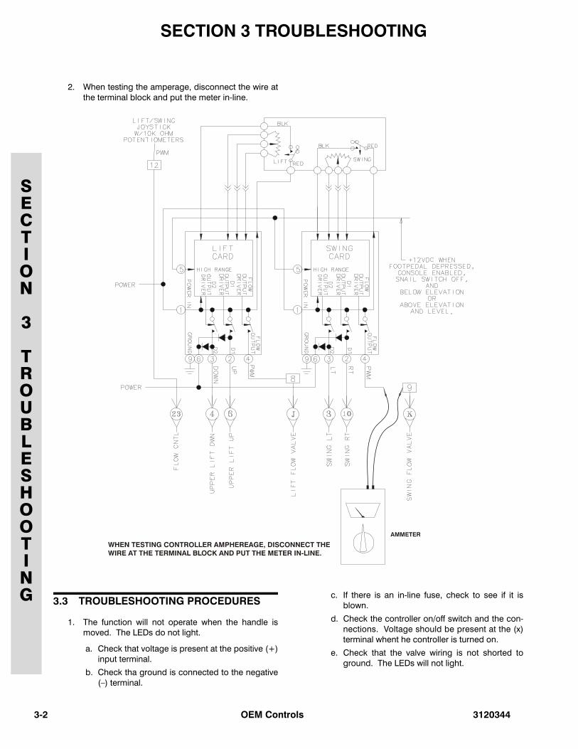
2. When testing the amperage, disconnect the wire atthe terminal block and put the meter in-line.
3.3 TROUBLESHOOTING PROCEDURES
1. The function will not operate when the handle ismoved. The LEDs do not light.
a. Check that voltage is present at the positive (+)input terminal.
b. Check tha ground is connected to the negative(–) terminal.
c. If there is an in-line fuse, check to see if it isblown.
d. Check the controller on/off switch and the con-nections. Voltage should be present at the (x)terminal whent he controller is turned on.
e. Check that the valve wiring is not shorted toground. The LEDs will not light.
OEM Controls 3120344
SECTION 3 TROUBLESHOOTING
SECTION
3
TROUBLESHOOTING
f. Check that valve wiring is not open. The LEDswill light, but the intensity will not vary.
g. Check trimpot settings. Fully CCW (counter-clockwise) turns output off, CW (clockwise) turnsoutput fully on.
2. The function jumps or lurches when turned on.
a. Perform "Threshold" adjustment procedures.
3. Function speed reacts too slowly or too quickly inrelation to handle deflection.
a. Check "IRS" (Ramp) trimpot adjustment. CW(clockwise) increases ramp time, CCW (counter-clockwise) decreases ramp time.
4. Controller will not switch between "HI" and "LO"range.
a. Check to see that source voltage is present atthe "R" terminal when in "HI" range, and absentwhen in "LO" range.
b. Check trimpot adjustments.
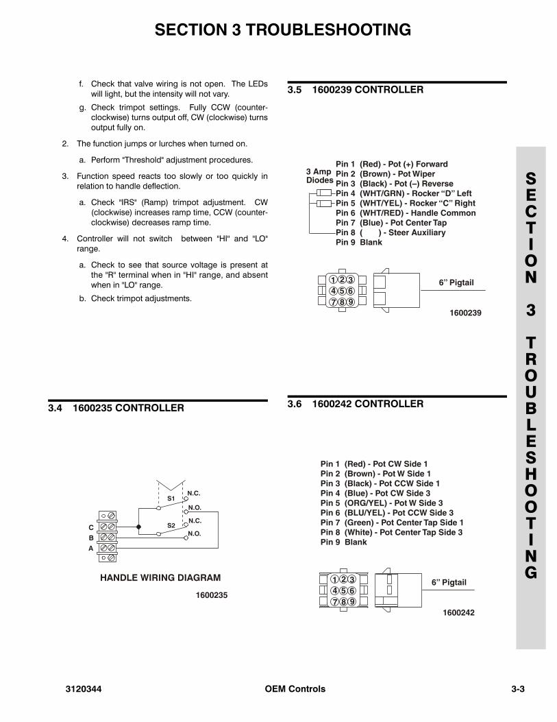
3.4 1600235 CONTROLLER
3.5 1600239 CONTROLLER
3.6 1600242 CONTROLLER
3120344 OEM Controls 3-3
3-4
SECTION 3 TROUBLESHOOTING
SECTION
3
TROUBLESHOOTING
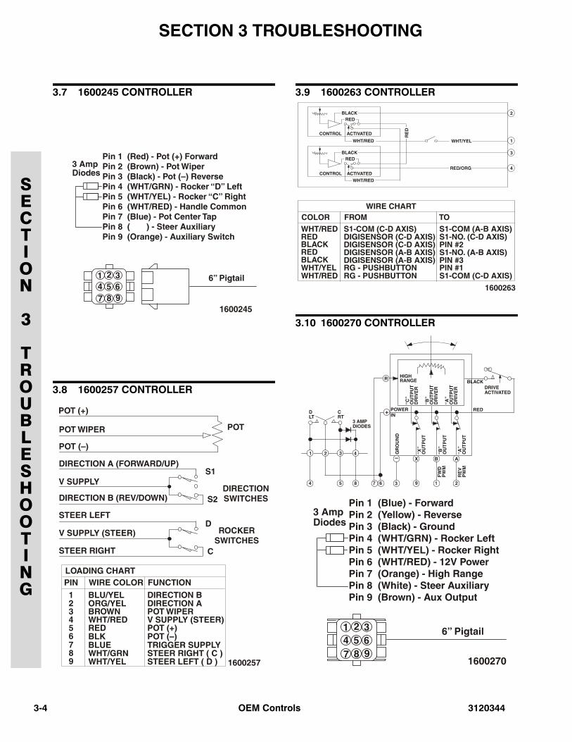
3.7 1600245 CONTROLLER
3.8 1600257 CONTROLLER
3.9 1600263 CONTROLLER
3.10 1600270 CONTROLLER
OEM Controls 3120344
SECTION 3 TROUBLESHOOTING
SECTION
3
TROUBLESHOOTING
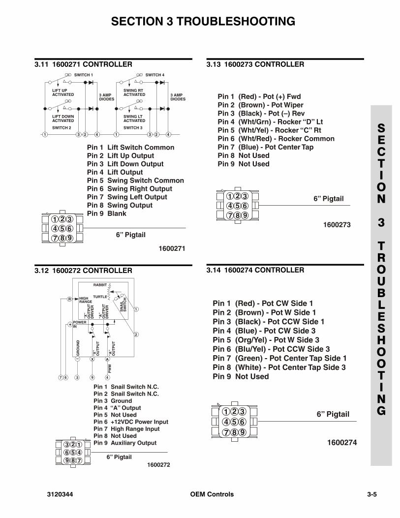
3.11 1600271 CONTROLLER
3.12 1600272 CONTROLLER
3.13 1600273 CONTROLLER
3.14 1600274 CONTROLLER
3120344 OEM Controls 3-5
3-6
SECTION 3 TROUBLESHOOTING
SECTION
3
TROUBLESHOOTING
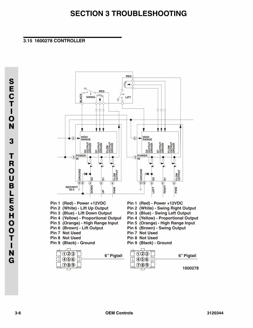
3.15 1600278 CONTROLLER
OEM Controls 3120344
SECTION 3 TROUBLESHOOTING
SECTION
3
TROUBLESHOOTING
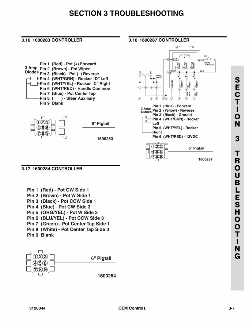
3.16 1600283 CONTROLLER
3.17 1600284 CONTROLLER
3.18 1600287 CONTROLLER
3120344 OEM Controls 3-7
3-8
SECTION 3 TROUBLESHOOTING
SECTION
3
TROUBLESHOOTING
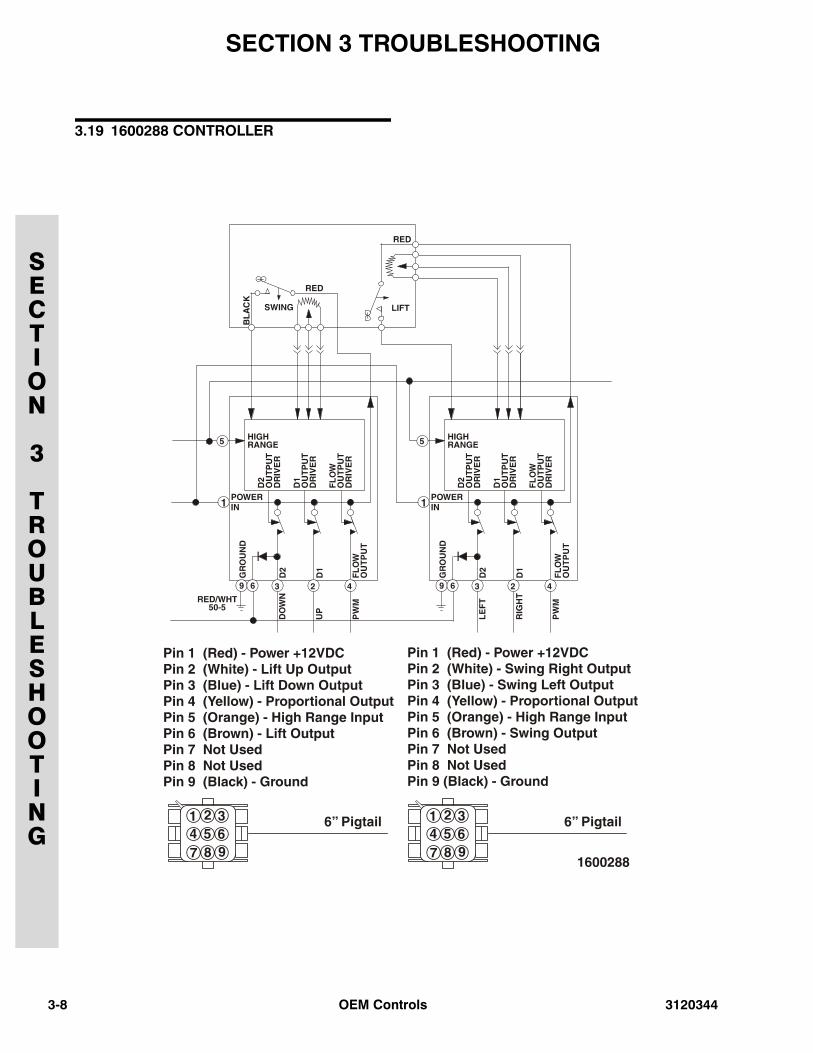
3.19 1600288 CONTROLLER
OEM Controls 3120344
SECTION 3 TROUBLESHOOTING
SECTION
3
TROUBLESHOOTING
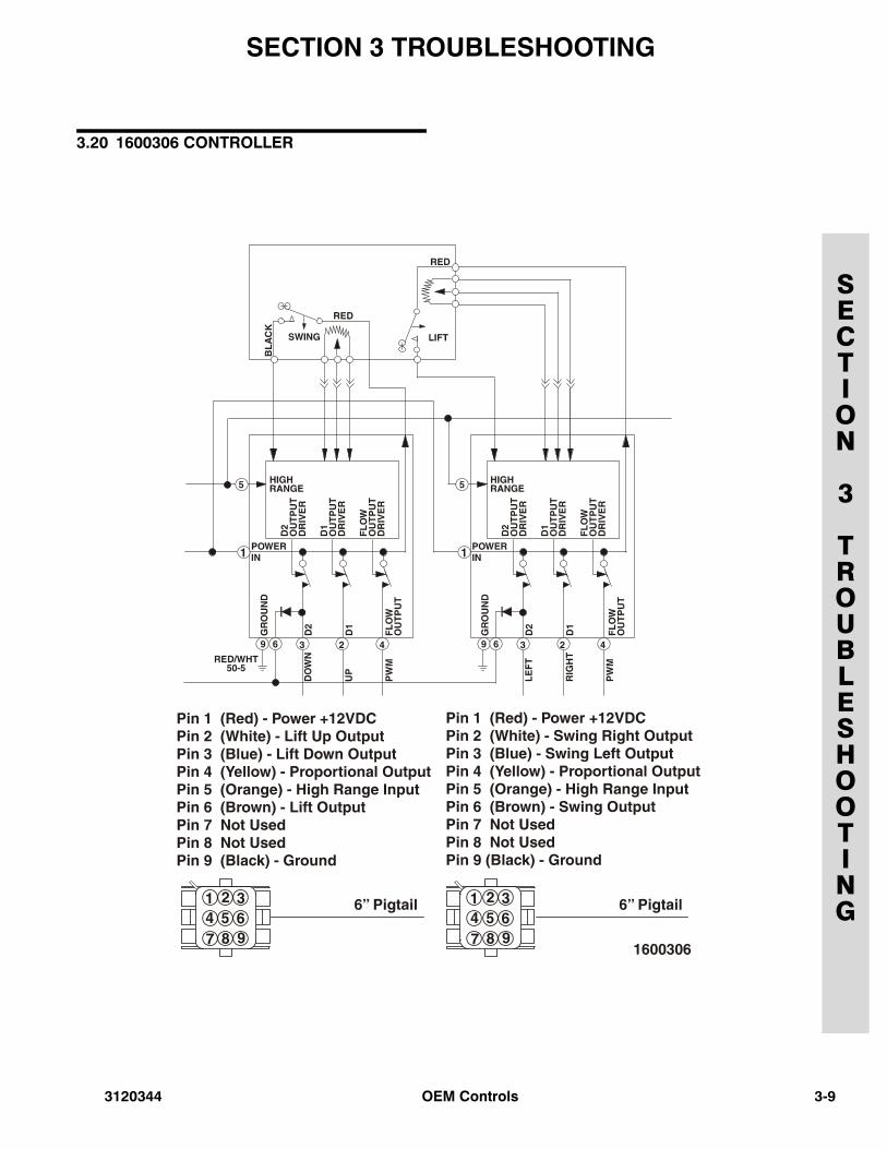
3.20 1600306 CONTROLLER
3120344 OEM Controls 3-9
3-1
SECTION 3 TROUBLESHOOTING
SECTION
3
TROUBLESHOOTING
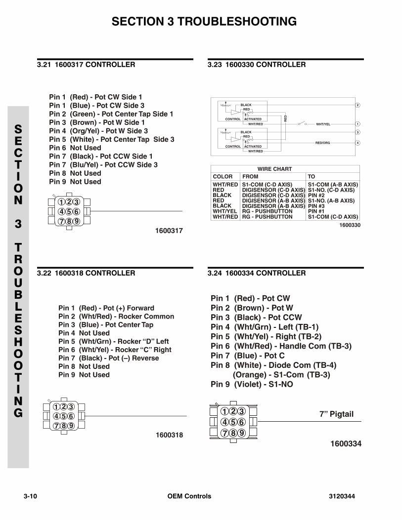
3.21 1600317 CONTROLLER
3.22 1600318 CONTROLLER
3.23 1600330 CONTROLLER
3.24 1600334 CONTROLLER
0 OEM Controls 3120344
3120344
SECTION 4 REPAIR PARTS
SECTION
4
REPAIR
PARTS
TABLE OF CONTENTS
FIGURE DESCRIPTION PAGE
4-1 CONTROLLER WITH SINGLE GATE & NO ROCKER SWITCH . . . . . . . . . . . . . . . . . . . . . . . . 4-24-2 CONTROLLER WITH SINGLE GATE & ROCKER SWITCH . . . . . . . . . . . . . . . . . . . . . . . . . . . 4-6
4-3 CONTROLLER WITH ROUND GATE & LIFT CAP . . . . . . . . . . . . . . . . . . . . . . . . . . . . . . . . . . 4-12
4-4 CONTROLLER WITH ROUND GATE & TRIGGER GRIP . . . . . . . . . . . . . . . . . . . . . . . . . . . . . 4-18
4-5 SPEED CONTROLLER WITH SNAIL/CREEP SPEED SWITCH . . . . . . . . . . . . . . . . . . . . . . . . 4-20
OEM Controls 4-1
SECTION 4 REPAIR PARTS
SECTION
4
REPAIR
PARTS
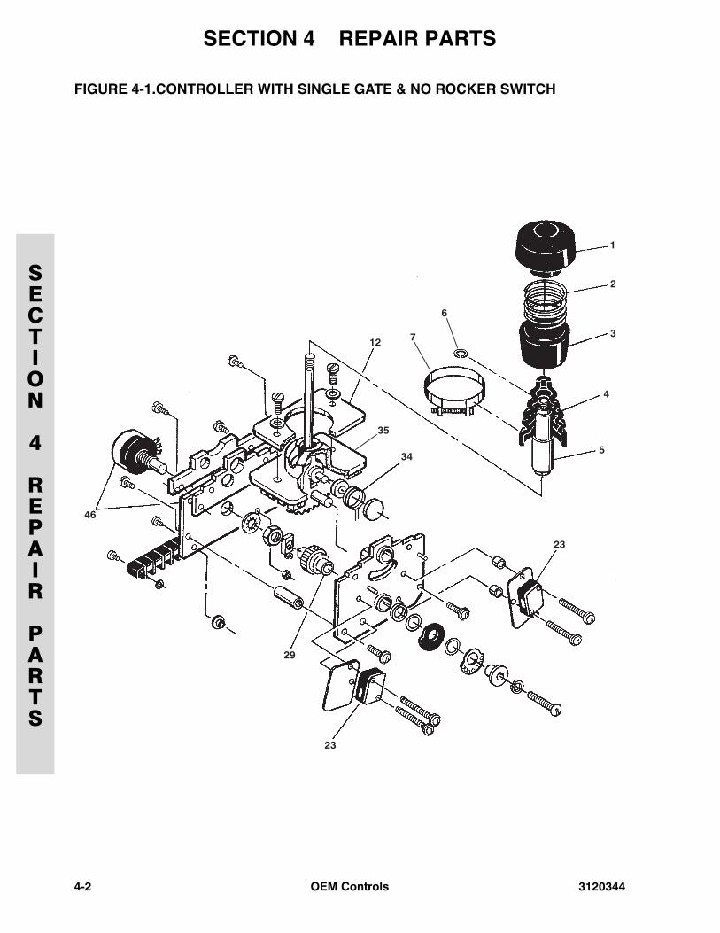
FIGURE 4-1.CONTROLLER WITH SINGLE GATE & NO ROCKER SWITCH
4-2 OEM Controls 3120344
SECTION 4 REPAIR PARTS
SECTION
4
REPAIR
PARTS
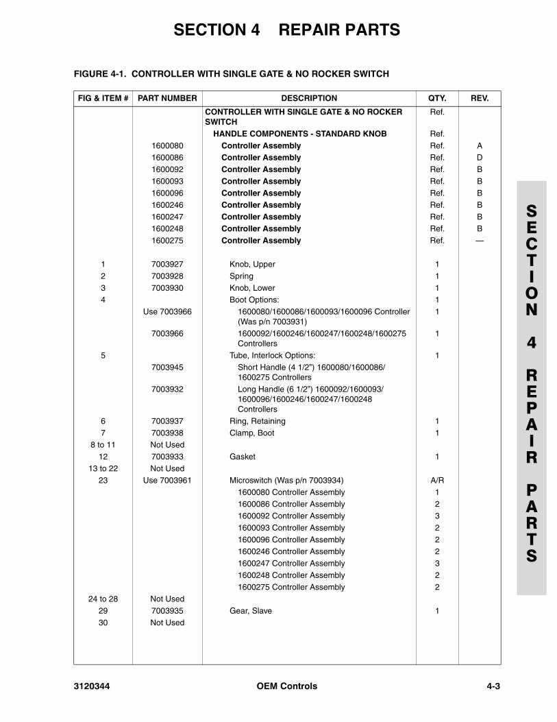
FIGURE 4-1. CONTROLLER WITH SINGLE GATE & NO ROCKER SWITCH
FIG & ITEM # PART NUMBER DESCRIPTION QTY. REV.
CONTROLLER WITH SINGLE GATE & NO ROCKER SWITCH
Ref.
HANDLE COMPONENTS - STANDARD KNOB Ref.
1600080 Controller Assembly Ref. A1600086 Controller Assembly Ref. D
1600092 Controller Assembly Ref. B
1600093 Controller Assembly Ref. B1600096 Controller Assembly Ref. B
1600246 Controller Assembly Ref. B
1600247 Controller Assembly Ref. B1600248 Controller Assembly Ref. B
1600275 Controller Assembly Ref. —
1 7003927 Knob, Upper 1
2 7003928 Spring 1
3 7003930 Knob, Lower 14 Boot Options: 1
Use 7003966 1600080/1600086/1600093/1600096 Controller (Was p/n 7003931)
1
7003966 1600092/1600246/1600247/1600248/1600275 Controllers
1
5 Tube, Interlock Options: 1
7003945 Short Handle (4 1/2”) 1600080/1600086/1600275 Controllers
7003932 Long Handle (6 1/2”) 1600092/1600093/1600096/1600246/1600247/1600248 Controllers
6 7003937 Ring, Retaining 1
7 7003938 Clamp, Boot 18 to 11 Not Used
12 7003933 Gasket 1
13 to 22 Not Used23 Use 7003961 Microswitch (Was p/n 7003934) A/R
1600080 Controller Assembly 1
1600086 Controller Assembly 21600092 Controller Assembly 3
1600093 Controller Assembly 2
1600096 Controller Assembly 21600246 Controller Assembly 2
1600247 Controller Assembly 3
1600248 Controller Assembly 2
1600275 Controller Assembly 224 to 28 Not Used
29 7003935 Gear, Slave 1
30 Not Used
3120344 OEM Controls 4-3
SECTION 4 REPAIR PARTS
SECTION
4
REPAIR
PARTS
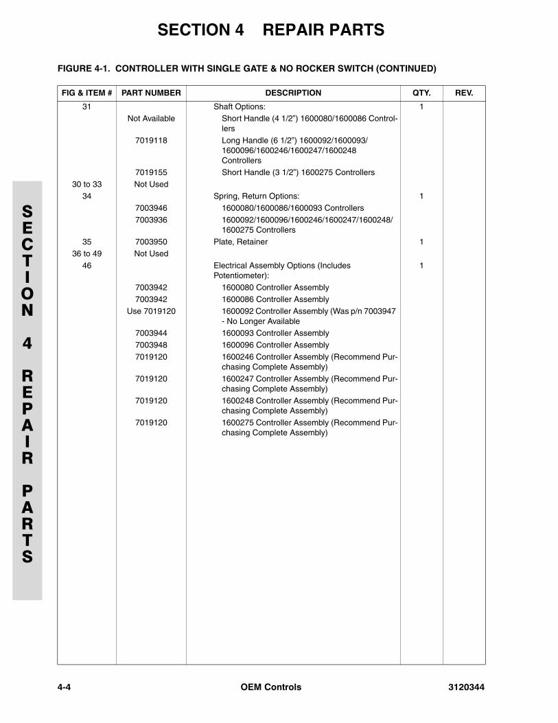
31 Shaft Options: 1Not Available Short Handle (4 1/2”) 1600080/1600086 Control-
lers
7019118 Long Handle (6 1/2”) 1600092/1600093/1600096/1600246/1600247/1600248 Controllers
7019155 Short Handle (3 1/2”) 1600275 Controllers
30 to 33 Not Used34 Spring, Return Options: 1
7003946 1600080/1600086/1600093 Controllers
7003936 1600092/1600096/1600246/1600247/1600248/1600275 Controllers
35 7003950 Plate, Retainer 136 to 49 Not Used
46 Electrical Assembly Options (Includes Potentiometer):
1
7003942 1600080 Controller Assembly
7003942 1600086 Controller AssemblyUse 7019120 1600092 Controller Assembly (Was p/n 7003947
- No Longer Available7003944 1600093 Controller Assembly
7003948 1600096 Controller Assembly
7019120 1600246 Controller Assembly (Recommend Pur-chasing Complete Assembly)
7019120 1600247 Controller Assembly (Recommend Pur-chasing Complete Assembly)
7019120 1600248 Controller Assembly (Recommend Pur-chasing Complete Assembly)
7019120 1600275 Controller Assembly (Recommend Pur-chasing Complete Assembly)
FIGURE 4-1. CONTROLLER WITH SINGLE GATE & NO ROCKER SWITCH (CONTINUED)
FIG & ITEM # PART NUMBER DESCRIPTION QTY. REV.
4-4 OEM Controls 3120344
SECTION 4 REPAIR PARTS
SECTION
4
REPAIR
PARTS
FIGURE 4-1. CONTROLLER WITH SINGLE GATE & NO ROCKER SWITCH (CONTINUED)
FIG & ITEM # PART NUMBER DESCRIPTION QTY. REV.
3120344 OEM Controls 4-5
SECTION 4 REPAIR PARTS
SECTION
4
REPAIR
PARTS
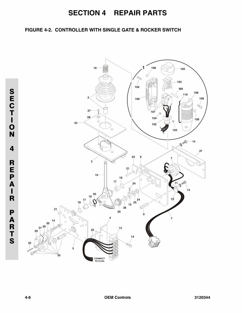
FIGURE 4-2. CONTROLLER WITH SINGLE GATE & ROCKER SWITCH
4-6 OEM Controls 3120344
SECTION 4 REPAIR PARTS
SECTION
4
REPAIR
PARTS
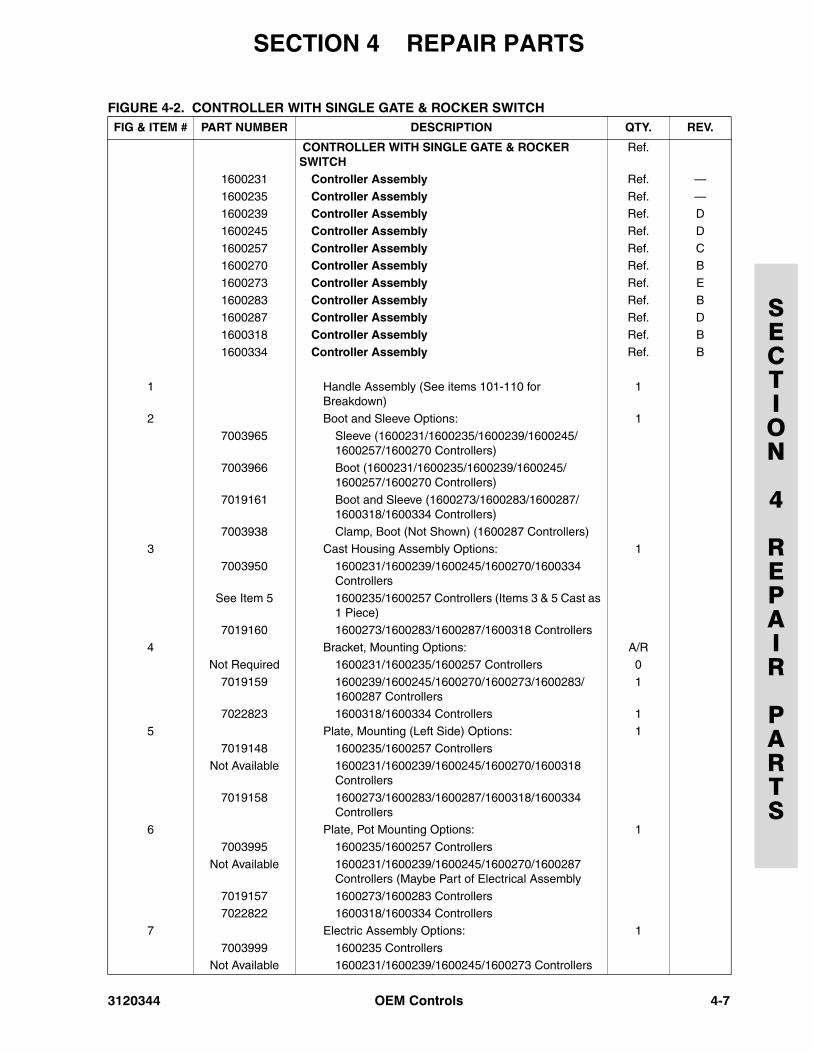
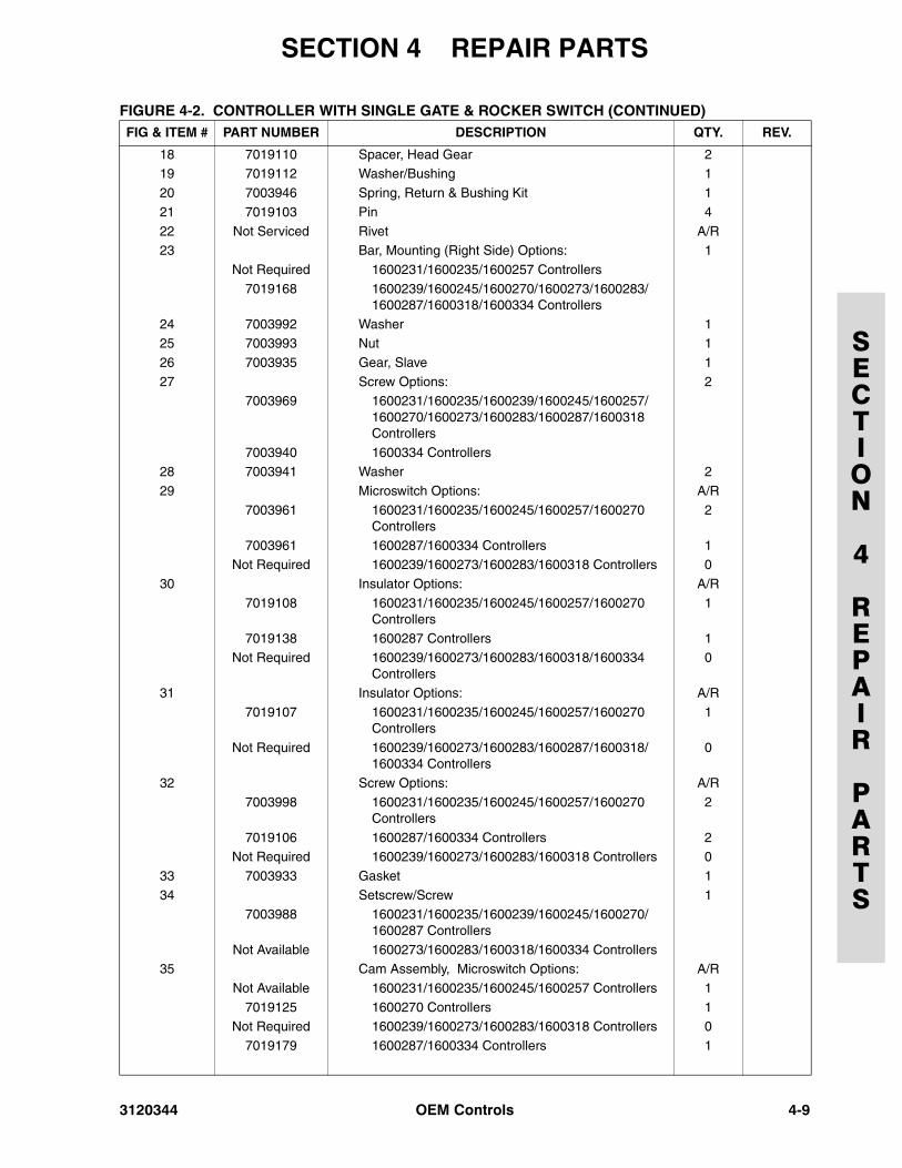
FIGURE 4-2. CONTROLLER WITH SINGLE GATE & ROCKER SWITCHFIG & ITEM # PART NUMBER DESCRIPTION QTY. REV.
CONTROLLER WITH SINGLE GATE & ROCKER SWITCH
Ref.
1600231 Controller Assembly Ref. —
1600235 Controller Assembly Ref. —1600239 Controller Assembly Ref. D
1600245 Controller Assembly Ref. D
1600257 Controller Assembly Ref. C1600270 Controller Assembly Ref. B
1600273 Controller Assembly Ref. E
1600283 Controller Assembly Ref. B1600287 Controller Assembly Ref. D
1600318 Controller Assembly Ref. B
1600334 Controller Assembly Ref. B
1 Handle Assembly (See items 101-110 for Breakdown)
1
2 Boot and Sleeve Options: 1
7003965 Sleeve (1600231/1600235/1600239/1600245/1600257/1600270 Controllers)
7003966 Boot (1600231/1600235/1600239/1600245/1600257/1600270 Controllers)
7019161 Boot and Sleeve (1600273/1600283/1600287/1600318/1600334 Controllers)
7003938 Clamp, Boot (Not Shown) (1600287 Controllers)3 Cast Housing Assembly Options: 1
7003950 1600231/1600239/1600245/1600270/1600334 Controllers
See Item 5 1600235/1600257 Controllers (Items 3 & 5 Cast as 1 Piece)
7019160 1600273/1600283/1600287/1600318 Controllers
4 Bracket, Mounting Options: A/RNot Required 1600231/1600235/1600257 Controllers 0
7019159 1600239/1600245/1600270/1600273/1600283/1600287 Controllers
1
7022823 1600318/1600334 Controllers 1
5 Plate, Mounting (Left Side) Options: 17019148 1600235/1600257 Controllers
Not Available 1600231/1600239/1600245/1600270/1600318 Controllers
7019158 1600273/1600283/1600287/1600318/1600334 Controllers
6 Plate, Pot Mounting Options: 1
7003995 1600235/1600257 Controllers
Not Available 1600231/1600239/1600245/1600270/1600287 Controllers (Maybe Part of Electrical Assembly
7019157 1600273/1600283 Controllers7022822 1600318/1600334 Controllers
7 Electric Assembly Options: 1
7003999 1600235 ControllersNot Available 1600231/1600239/1600245/1600273 Controllers
3120344 OEM Controls 4-7
SECTION 4 REPAIR PARTS
SECTION
4
REPAIR
PARTS
7019101 1600257 Controllers7019124 1600270/1600287 Controllers
7019191 1600273 Controllers
7019156 1600283/1600334 Controllers
7022824 1600318 ControllersPotentiometer Options: 1
Use 7011925 1600235/1600257 Controllers (Was p/n 7003997)
7003970 1600239 Controllers
7003974 1600239/1600245/1600273 Controllers Not Available 1600231/1600270/1600283/1600287/
1600318 Controllers 8 Not Used
9 7019115 Stand-Off 2
10 Shaft & Sector Gear Options: 17003963 1600231/1600239/1600245 Controllers
7019100 1600235 Controllers
7019102 1600257 Controllers7019105 1600270 Controllers
7019155 1600273/1600283/1600287/1600318/1600334 Controllers
11 7019151 Tie-Strap A/R
12 Clamp, Wire A/RNot Required 1600231/1600235/1600239/1600257/1600245/
1600270/1600287 Controllers0
7019154 1600273/1600283/1600318/1600334 Controllers 2
13 Strip, Terminal Options: A/R
7003991 1600235/1600257 Controllers (3 Position) 17003986 1600273/1600318 Controllers (3 Position) 1
Not Required 1600231/1600239/1600245 Controllers 0
7019153 1600270/1600283/1600287 Controllers (5 Position)
1
7022828 1600334 Controllers (5 Position) 114 Screw Options: A/R
7003994 1600231/1600235/1600239/1600245/1600257/1600270/1600273/1600287/1600318 Controllers
2
7019155 1600283 Controllers 8
7019117 1600334 Controllers 715 Potentiometer Coupling Options: 1
7019114 1600231/1600235/1600239/1600245/1600257/1600270 Controllers
7019163 1600273/1600283/1600287/1600318/1600334 Controllers
16 7019162 Spring 1
17 Bearing Options: 2
7019111 1600231/1600235/1600239/1600245/1600257/1600270/1600273/1600283/1600287/1600318 Controllers
7022827 1600334 Controllers
FIGURE 4-2. CONTROLLER WITH SINGLE GATE & ROCKER SWITCH (CONTINUED)FIG & ITEM # PART NUMBER DESCRIPTION QTY. REV.
4-8 OEM Controls 3120344
SECTION 4 REPAIR PARTS
SECTION
4
REPAIR
PARTS
18 7019110 Spacer, Head Gear 219 7019112 Washer/Bushing 1
20 7003946 Spring, Return & Bushing Kit 1
21 7019103 Pin 4
22 Not Serviced Rivet A/R23 Bar, Mounting (Right Side) Options: 1
Not Required 1600231/1600235/1600257 Controllers
7019168 1600239/1600245/1600270/1600273/1600283/1600287/1600318/1600334 Controllers
24 7003992 Washer 125 7003993 Nut 1
26 7003935 Gear, Slave 1
27 Screw Options: 27003969 1600231/1600235/1600239/1600245/1600257/
1600270/1600273/1600283/1600287/1600318 Controllers
7003940 1600334 Controllers28 7003941 Washer 2
29 Microswitch Options: A/R
7003961 1600231/1600235/1600245/1600257/1600270 Controllers
2
7003961 1600287/1600334 Controllers 1Not Required 1600239/1600273/1600283/1600318 Controllers 0
30 Insulator Options: A/R
7019108 1600231/1600235/1600245/1600257/1600270 Controllers
1
7019138 1600287 Controllers 1Not Required 1600239/1600273/1600283/1600318/1600334
Controllers0
31 Insulator Options: A/R
7019107 1600231/1600235/1600245/1600257/1600270 Controllers
1
Not Required 1600239/1600273/1600283/1600287/1600318/1600334 Controllers
0
32 Screw Options: A/R
7003998 1600231/1600235/1600245/1600257/1600270 Controllers
2
7019106 1600287/1600334 Controllers 2Not Required 1600239/1600273/1600283/1600318 Controllers 0
33 7003933 Gasket 1
34 Setscrew/Screw 17003988 1600231/1600235/1600239/1600245/1600270/
1600287 Controllers
Not Available 1600273/1600283/1600318/1600334 Controllers35 Cam Assembly, Microswitch Options: A/R
Not Available 1600231/1600235/1600245/1600257 Controllers 1
7019125 1600270 Controllers 1Not Required 1600239/1600273/1600283/1600318 Controllers 0
7019179 1600287/1600334 Controllers 1
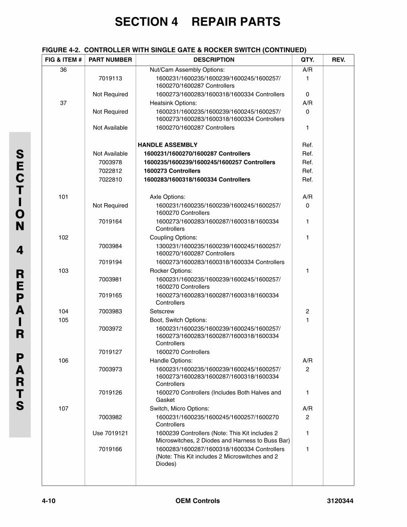
FIGURE 4-2. CONTROLLER WITH SINGLE GATE & ROCKER SWITCH (CONTINUED)FIG & ITEM # PART NUMBER DESCRIPTION QTY. REV.
3120344 OEM Controls 4-9
SECTION 4 REPAIR PARTS
SECTION
4
REPAIR
PARTS
36 Nut/Cam Assembly Options: A/R7019113 1600231/1600235/1600239/1600245/1600257/
1600270/1600287 Controllers1
Not Required 1600273/1600283/1600318/1600334 Controllers 0
37 Heatsink Options: A/R
Not Required 1600231/1600235/1600239/1600245/1600257/1600273/1600283/1600318/1600334 Controllers
0
Not Available 1600270/1600287 Controllers 1
HANDLE ASSEMBLY Ref.
Not Available 1600231/1600270/1600287 Controllers Ref.
7003978 1600235/1600239/1600245/1600257 Controllers Ref.7022812 1600273 Controllers Ref.
7022810 1600283/1600318/1600334 Controllers Ref.
101 Axle Options: A/R
Not Required 1600231/1600235/1600239/1600245/1600257/1600270 Controllers
0
7019164 1600273/1600283/1600287/1600318/1600334 Controllers
1
102 Coupling Options: 1
7003984 1300231/1600235/1600239/1600245/1600257/1600270/1600287 Controllers
7019194 1600273/1600283/1600318/1600334 Controllers103 Rocker Options: 1
7003981 1600231/1600235/1600239/1600245/1600257/1600270 Controllers
7019165 1600273/1600283/1600287/1600318/1600334 Controllers
104 7003983 Setscrew 2
105 Boot, Switch Options: 17003972 1600231/1600235/1600239/1600245/1600257/
1600273/1600283/1600287/1600318/1600334 Controllers
7019127 1600270 Controllers 106 Handle Options: A/R
7003973 1600231/1600235/1600239/1600245/1600257/1600273/1600283/1600287/1600318/1600334 Controllers
2
7019126 1600270 Controllers (Includes Both Halves and Gasket
1
107 Switch, Micro Options: A/R
7003982 1600231/1600235/1600245/1600257/1600270 Controllers
2
Use 7019121 1600239 Controllers (Note: This Kit includes 2 Microswitches, 2 Diodes and Harness to Buss Bar)
1
7019166 1600283/1600287/1600318/1600334 Controllers (Note: This Kit includes 2 Microswitches and 2 Diodes)
1
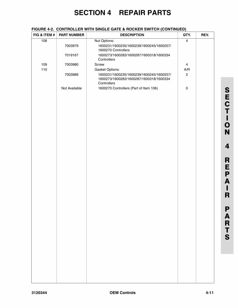
FIGURE 4-2. CONTROLLER WITH SINGLE GATE & ROCKER SWITCH (CONTINUED)FIG & ITEM # PART NUMBER DESCRIPTION QTY. REV.
4-10 OEM Controls 3120344
SECTION 4 REPAIR PARTS
SECTION
4
REPAIR
PARTS
108 Nut Options: 47003979 1600231/1600235/1600239/1600245/1600257/
1600270 Controllers7019167 1600273/1600283/1600287/1600318/1600334
Controllers
109 7003980 Screw 4110 Gasket Options: A/R
7003989 1600231/1600235/1600239/1600245/1600257/1600273/1600283/1600287/1600318/1600334 Controllers
2
Not Available 1600270 Controllers (Part of Item 106) 0
FIGURE 4-2. CONTROLLER WITH SINGLE GATE & ROCKER SWITCH (CONTINUED)FIG & ITEM # PART NUMBER DESCRIPTION QTY. REV.
3120344 OEM Controls 4-11
SECTION 4 REPAIR PARTS
SECTION
4
REPAIR
PARTS
FIGURE 4-3. CONTROLLER WITH ROUND GATE AND LIFT CAP
4-12 OEM Controls 3120344
SECTION 4 REPAIR PARTS
SECTION
4
REPAIR
PARTS
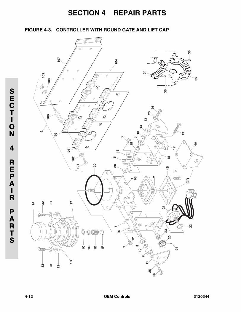
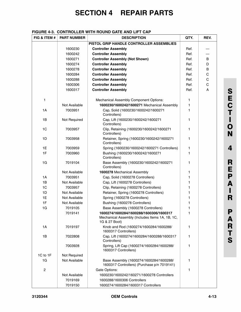
FIGURE 4-3. CONTROLLER WITH ROUND GATE AND LIFT CAPFIG & ITEM # PART NUMBER DESCRIPTION QTY. REV.
PISTOL GRIP HANDLE CONTROLLER ASSEMBLIES1600230 Controller Assembly Ref. —
1600242 Controller Assembly Ref. —
1600271 Controller Assembly (Not Shown) Ref. B
1600274 Controller Assembly Ref. D1600278 Controller Assembly Ref. B
1600284 Controller Assembly Ref. C
1600288 Controller Assembly Ref. C1600306 Controller Assembly Ref. C
1600317 Controller Assembly Ref. A
1 Mechanical Assembly Component Options: 1
Not Available 1600230/1600242/1600271 Mechanical Assembly 1
1A 7003951 Cap, Solid (1600230/1600242/1600271 Controllers)
1
1B Not Required Cap, Lift (1600230/1600242/1600271 Controllers)
1
1C 7003957 Clip, Retaining (1600230/1600242/1600271 Controllers)
1
1D 7003958 Retainer, Spring (1600230/1600242/1600271 Controllers)
1
1E 7003959 Spring (1600230/1600242/1600271 Controllers) 11F 7003960 Bushing (1600230/1600242/1600271
Controllers)1
1G 7019104 Base Assembly (1600230/1600242/1600271 Controllers)
1
Not Available 1600278 Mechanical Assembly 1
1A 7003951 Cap, Solid (1600278 Controllers) 1
1B Not Available Cap, Lift (1600278 Controllers) 11C 7003957 Clip, Retaining (1600278 Controllers) 1
1D Not Available Retainer, Spring (1600278 Controllers) 1
1E Not Available Spring (1600278 Controllers) 11F Not Available Bushing (1600278 Controllers) 1
1G 7019105 Base Assembly (1600278 Controllers) 1
7019141 1600274/1600284/1600288/1600306/1600317 Mechanical Assembly (Includes Items 1A, 1B, 1C, 1G & 27 Boot)
1
1A 7019197 Knob and Rod (1600274/1600284/1600288/1600317 Controllers)
1
1B 7022808 Cap, Lift (1600274/1600284/1600288/1600317 Controllers)
1
7003928 Spring, Lift Cap (1600274/1600284/1600288/1600317 Controllers)
1
1C to 1F Not Required
1G Not Available Base Assembly (1600274/1600284/1600288/1600317 Controllers) (Purchase p/n 7019141)
1
2 Gate Options: 1
Not Available 1600230/1600242/160271/1600278 Controllers7019169 1600288/1600306 Controllers
7019150 1600274/1600284/1600317 Controllers
3120344 OEM Controls 4-13
SECTION 4 REPAIR PARTS
SECTION
4
REPAIR
PARTS
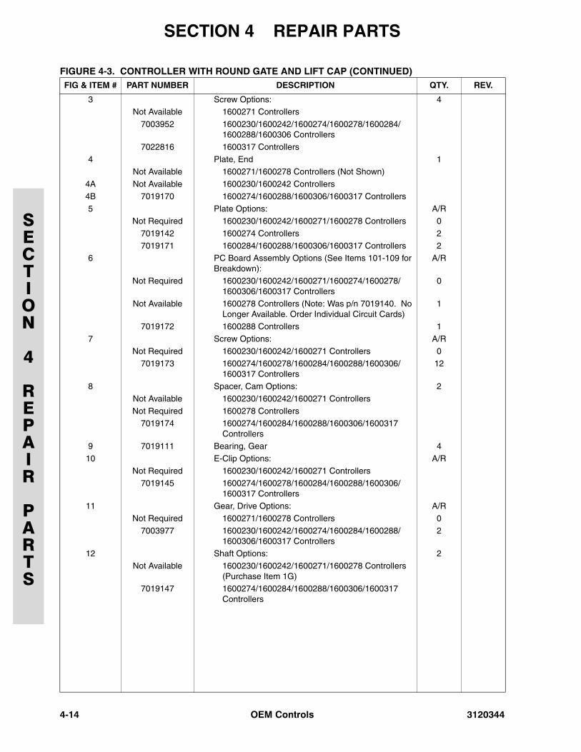
3 Screw Options: 4Not Available 1600271 Controllers
7003952 1600230/1600242/1600274/1600278/1600284/1600288/1600306 Controllers
7022816 1600317 Controllers
4 Plate, End 1
Not Available 1600271/1600278 Controllers (Not Shown)4A Not Available 1600230/1600242 Controllers
4B 7019170 1600274/1600288/1600306/1600317 Controllers
5 Plate Options: A/RNot Required 1600230/1600242/1600271/1600278 Controllers 0
7019142 1600274 Controllers 2
7019171 1600284/1600288/1600306/1600317 Controllers 26 PC Board Assembly Options (See Items 101-109 for
Breakdown):A/R
Not Required 1600230/1600242/1600271/1600274/1600278/1600306/1600317 Controllers
0
Not Available 1600278 Controllers (Note: Was p/n 7019140. No Longer Available. Order Individual Circuit Cards)
1
7019172 1600288 Controllers 1
7 Screw Options: A/R
Not Required 1600230/1600242/1600271 Controllers 07019173 1600274/1600278/1600284/1600288/1600306/
1600317 Controllers12
8 Spacer, Cam Options: 2
Not Available 1600230/1600242/1600271 Controllers
Not Required 1600278 Controllers7019174 1600274/1600284/1600288/1600306/1600317
Controllers9 7019111 Bearing, Gear 4
10 E-Clip Options: A/R
Not Required 1600230/1600242/1600271 Controllers7019145 1600274/1600278/1600284/1600288/1600306/
1600317 Controllers11 Gear, Drive Options: A/R
Not Required 1600271/1600278 Controllers 0
7003977 1600230/1600242/1600274/1600284/1600288/1600306/1600317 Controllers
2
12 Shaft Options: 2Not Available 1600230/1600242/1600271/1600278 Controllers
(Purchase Item 1G)7019147 1600274/1600284/1600288/1600306/1600317
Controllers
FIGURE 4-3. CONTROLLER WITH ROUND GATE AND LIFT CAP (CONTINUED)FIG & ITEM # PART NUMBER DESCRIPTION QTY. REV.
4-14 OEM Controls 3120344
SECTION 4 REPAIR PARTS
SECTION
4
REPAIR
PARTS
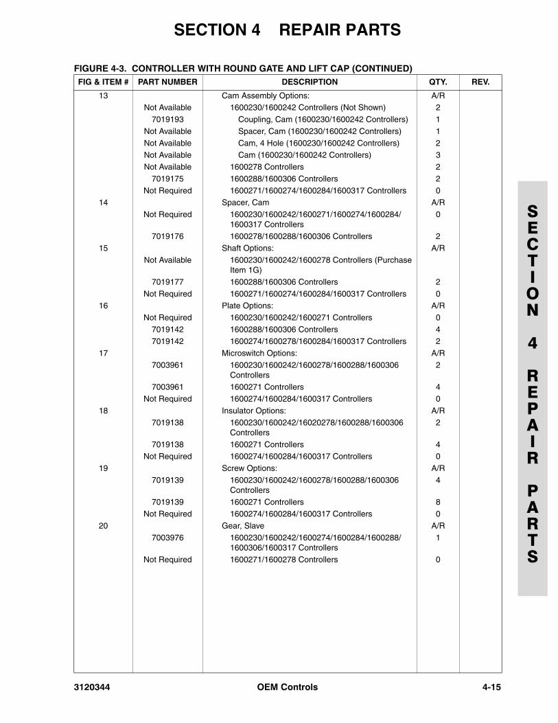
13 Cam Assembly Options: A/RNot Available 1600230/1600242 Controllers (Not Shown) 2
7019193 Coupling, Cam (1600230/1600242 Controllers) 1
Not Available Spacer, Cam (1600230/1600242 Controllers) 1
Not Available Cam, 4 Hole (1600230/1600242 Controllers) 2Not Available Cam (1600230/1600242 Controllers) 3
Not Available 1600278 Controllers 2
7019175 1600288/1600306 Controllers 2Not Required 1600271/1600274/1600284/1600317 Controllers 0
14 Spacer, Cam A/R
Not Required 1600230/1600242/1600271/1600274/1600284/1600317 Controllers
0
7019176 1600278/1600288/1600306 Controllers 215 Shaft Options: A/R
Not Available 1600230/1600242/1600278 Controllers (Purchase Item 1G)
7019177 1600288/1600306 Controllers 2
Not Required 1600271/1600274/1600284/1600317 Controllers 016 Plate Options: A/R
Not Required 1600230/1600242/1600271 Controllers 0
7019142 1600288/1600306 Controllers 47019142 1600274/1600278/1600284/1600317 Controllers 2
17 Microswitch Options: A/R
7003961 1600230/1600242/1600278/1600288/1600306 Controllers
2
7003961 1600271 Controllers 4Not Required 1600274/1600284/1600317 Controllers 0
18 Insulator Options: A/R
7019138 1600230/1600242/16020278/1600288/1600306 Controllers
2
7019138 1600271 Controllers 4Not Required 1600274/1600284/1600317 Controllers 0
19 Screw Options: A/R
7019139 1600230/1600242/1600278/1600288/1600306 Controllers
4
7019139 1600271 Controllers 8Not Required 1600274/1600284/1600317 Controllers 0
20 Gear, Slave A/R
7003976 1600230/1600242/1600274/1600284/1600288/1600306/1600317 Controllers
1
Not Required 1600271/1600278 Controllers 0
FIGURE 4-3. CONTROLLER WITH ROUND GATE AND LIFT CAP (CONTINUED)FIG & ITEM # PART NUMBER DESCRIPTION QTY. REV.
3120344 OEM Controls 4-15
SECTION 4 REPAIR PARTS
SECTION
4
REPAIR
PARTS
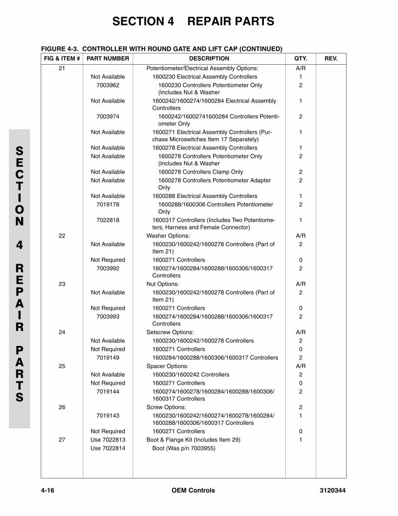
21 Potentiometer/Electrical Assembly Options: A/RNot Available 1600230 Electrical Assembly Controllers 1
7003962 1600230 Controllers Potentiometer Only (Includes Nut & Washer
2
Not Available 1600242/1600274/1600284 Electrical Assembly Controllers
1
7003974 1600242/16002741600284 Controllers Potenti-ometer Only
2
Not Available 1600271 Electrical Assembly Controllers (Pur-chase Microswitches Item 17 Separately)
1
Not Available 1600278 Electrical Assembly Controllers 1
Not Available 1600278 Controllers Potentiometer Only (Includes Nut & Washer
2
Not Available 1600278 Controllers Clamp Only 2
Not Available 1600278 Controllers Potentiometer Adapter Only
2
Not Available 1600288 Electrical Assembly Controllers 17019178 1600288/1600306 Controllers Potentiometer
Only2
7022818 1600317 Controllers (Includes Two Potentiome-ters, Harness and Female Connector)
1
22 Washer Options: A/R
Not Available 1600230/1600242/1600278 Controllers (Part of Item 21)
2
Not Required 1600271 Controllers 0
7003992 1600274/1600284/1600288/1600306/1600317 Controllers
2
23 Nut Options: A/RNot Available 1600230/1600242/1600278 Controllers (Part of
Item 21)2
Not Required 1600271 Controllers 0
7003993 1600274/1600284/1600288/1600306/1600317 Controllers
2
24 Setscrew Options: A/R
Not Available 1600230/1600242/1600278 Controllers 2Not Required 1600271 Controllers 0
7019149 1600284/1600288/1600306/1600317 Controllers 2
25 Spacer Options: A/RNot Available 1600230/1600242 Controllers 2
Not Required 1600271 Controllers 0
7019144 1600274/1600278/1600284/1600288/1600306/1600317 Controllers
2
26 Screw Options: 27019143 1600230/1600242/1600274/1600278/1600284/
1600288/1600306/1600317 Controllers1
Not Required 1600271 Controllers 027 Use 7022813 Boot & Flange Kit (Includes Item 29) 1
Use 7022814 Boot (Was p/n 7003955)
FIGURE 4-3. CONTROLLER WITH ROUND GATE AND LIFT CAP (CONTINUED)FIG & ITEM # PART NUMBER DESCRIPTION QTY. REV.
4-16 OEM Controls 3120344
SECTION 4 REPAIR PARTS
SECTION
4
REPAIR
PARTS
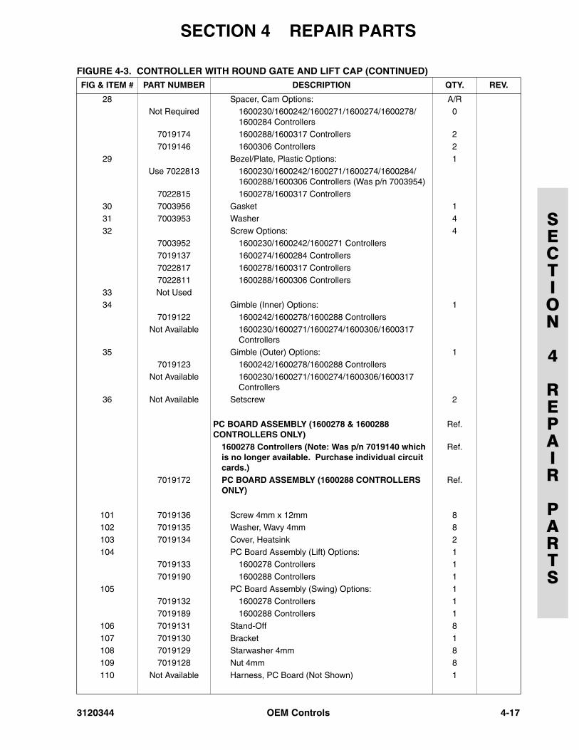
28 Spacer, Cam Options: A/RNot Required 1600230/1600242/1600271/1600274/1600278/
1600284 Controllers0
7019174 1600288/1600317 Controllers 2
7019146 1600306 Controllers 2
29 Bezel/Plate, Plastic Options: 1
Use 7022813 1600230/1600242/1600271/1600274/1600284/1600288/1600306 Controllers (Was p/n 7003954)
7022815 1600278/1600317 Controllers30 7003956 Gasket 1
31 7003953 Washer 4
32 Screw Options: 47003952 1600230/1600242/1600271 Controllers
7019137 1600274/1600284 Controllers
7022817 1600278/1600317 Controllers7022811 1600288/1600306 Controllers
33 Not Used
34 Gimble (Inner) Options: 17019122 1600242/1600278/1600288 Controllers
Not Available 1600230/1600271/1600274/1600306/1600317 Controllers
35 Gimble (Outer) Options: 1
7019123 1600242/1600278/1600288 ControllersNot Available 1600230/1600271/1600274/1600306/1600317
Controllers36 Not Available Setscrew 2
PC BOARD ASSEMBLY (1600278 & 1600288 CONTROLLERS ONLY)
Ref.
1600278 Controllers (Note: Was p/n 7019140 which is no longer available. Purchase individual circuit cards.)
Ref.
7019172 PC BOARD ASSEMBLY (1600288 CONTROLLERS ONLY)
Ref.
101 7019136 Screw 4mm x 12mm 8102 7019135 Washer, Wavy 4mm 8
103 7019134 Cover, Heatsink 2
104 PC Board Assembly (Lift) Options: 17019133 1600278 Controllers 1
7019190 1600288 Controllers 1
105 PC Board Assembly (Swing) Options: 17019132 1600278 Controllers 1
7019189 1600288 Controllers 1
106 7019131 Stand-Off 8
107 7019130 Bracket 1108 7019129 Starwasher 4mm 8
109 7019128 Nut 4mm 8
110 Not Available Harness, PC Board (Not Shown) 1
FIGURE 4-3. CONTROLLER WITH ROUND GATE AND LIFT CAP (CONTINUED)FIG & ITEM # PART NUMBER DESCRIPTION QTY. REV.
3120344 OEM Controls 4-17
SECTION 4 REPAIR PARTS
SECTION
4
REPAIR
PARTS
FIGURE 4-4. CONTROLLER WITH ROUND GATE AND TRIGGER GRIP
4-18 OEM Controls 3120344
SECTION 4 REPAIR PARTS
SECTION
4
REPAIR
PARTS
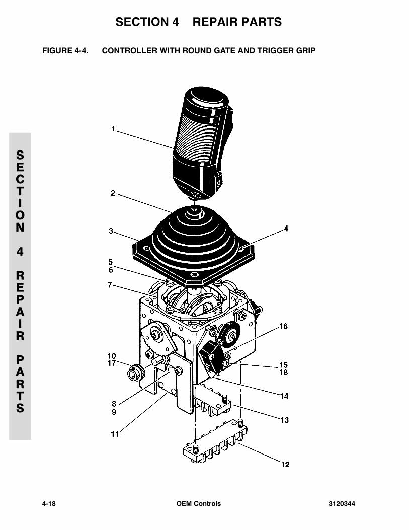
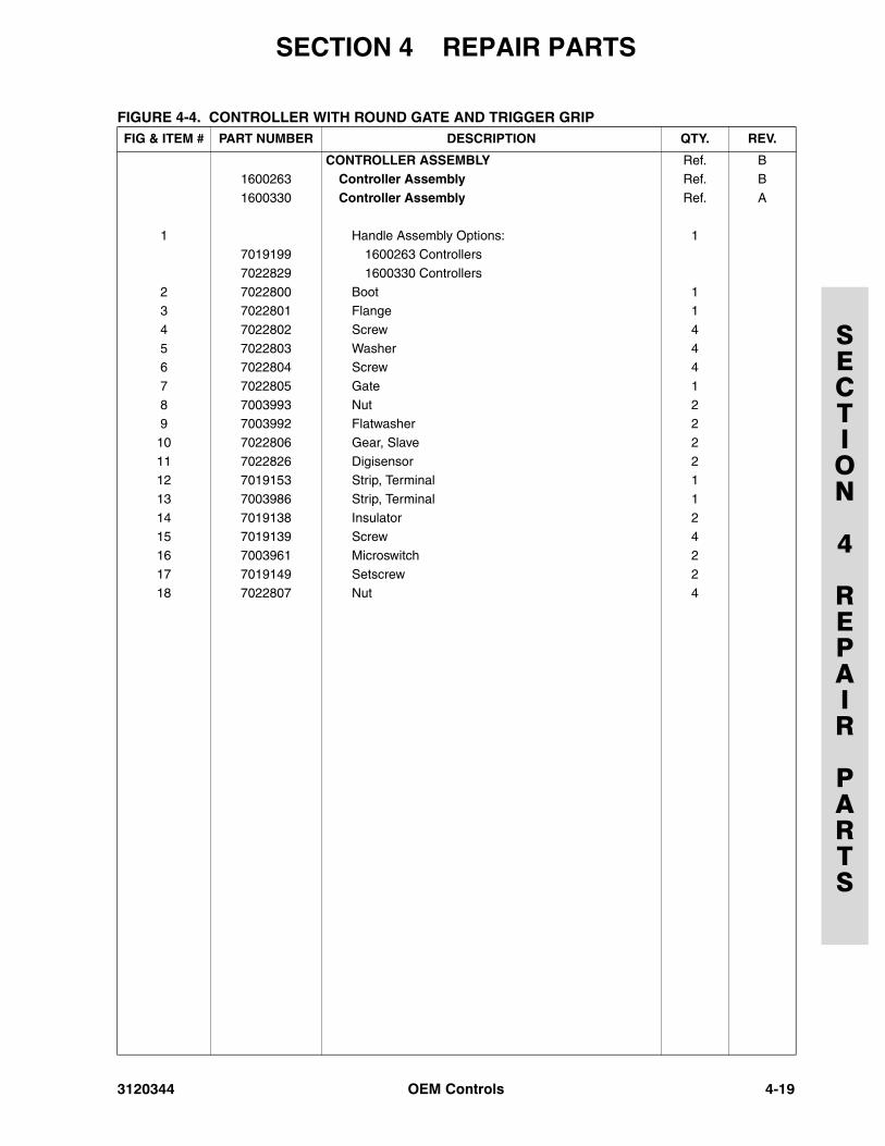
FIGURE 4-4. CONTROLLER WITH ROUND GATE AND TRIGGER GRIPFIG & ITEM # PART NUMBER DESCRIPTION QTY. REV.
CONTROLLER ASSEMBLY Ref. B1600263 Controller Assembly Ref. B
1600330 Controller Assembly Ref. A
1 Handle Assembly Options: 17019199 1600263 Controllers
7022829 1600330 Controllers
2 7022800 Boot 13 7022801 Flange 1
4 7022802 Screw 4
5 7022803 Washer 46 7022804 Screw 4
7 7022805 Gate 1
8 7003993 Nut 29 7003992 Flatwasher 2
10 7022806 Gear, Slave 2
11 7022826 Digisensor 212 7019153 Strip, Terminal 1
13 7003986 Strip, Terminal 1
14 7019138 Insulator 215 7019139 Screw 4
16 7003961 Microswitch 2
17 7019149 Setscrew 218 7022807 Nut 4
3120344 OEM Controls 4-19
SECTION 4 REPAIR PARTS
SECTION
4
REPAIR
PARTS
FIGURE 4-5.SPEED CONTROLLER WITH SNAIL/CREEP SPEED SWITCH
4-20 OEM Controls 3120344
SECTION 4 REPAIR PARTS
SECTION
4
REPAIR
PARTS
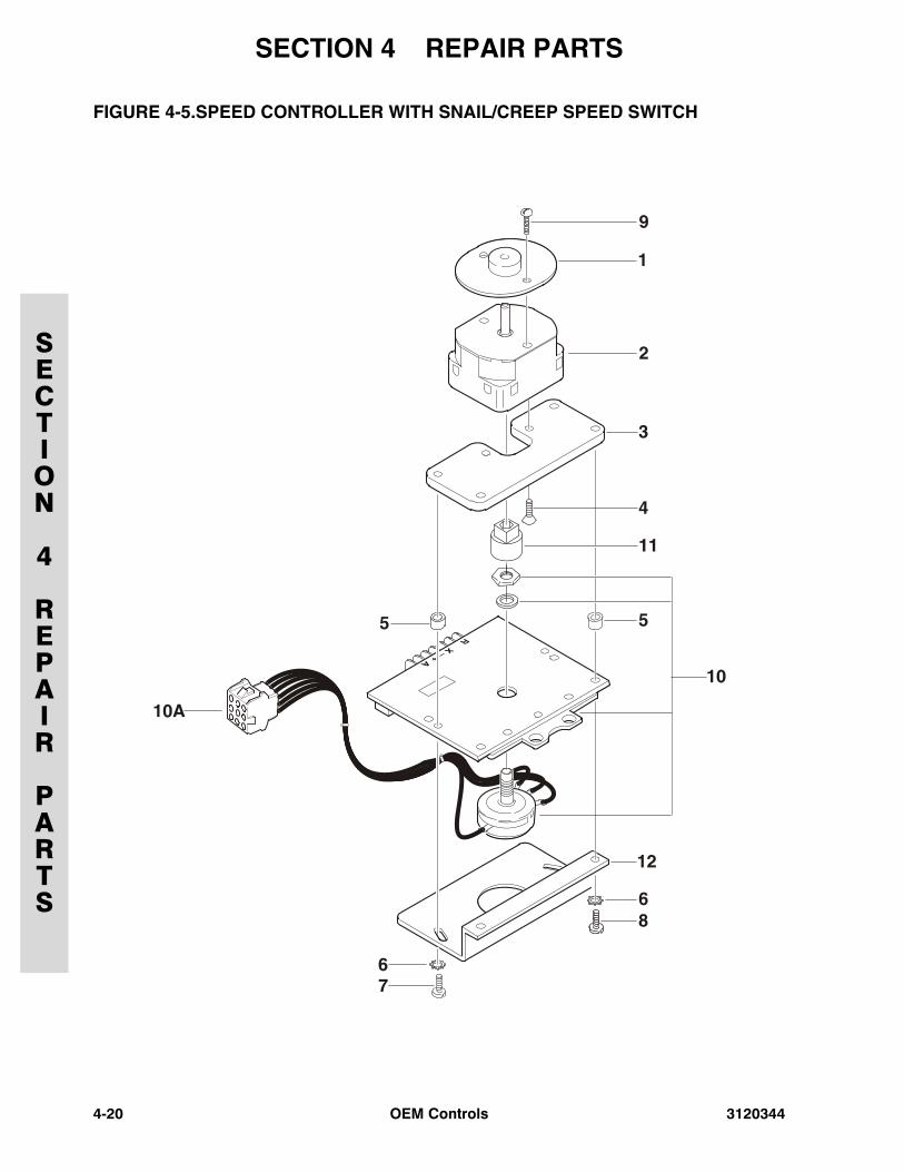
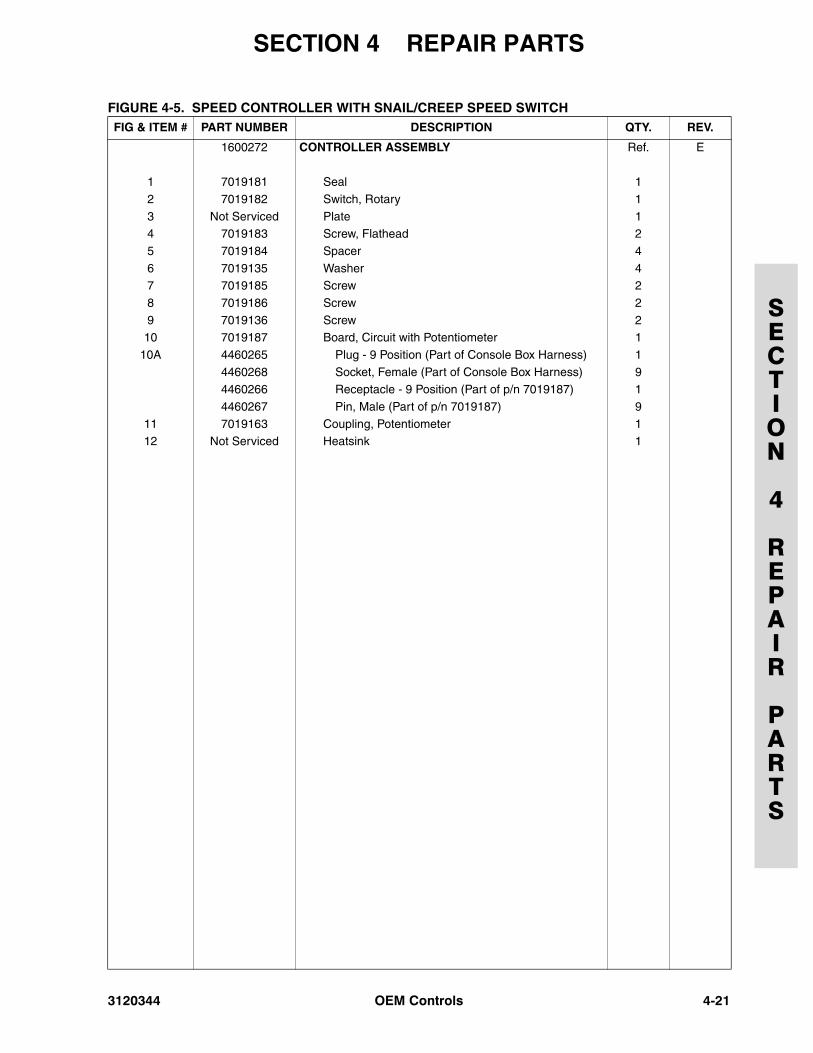
FIGURE 4-5. SPEED CONTROLLER WITH SNAIL/CREEP SPEED SWITCHFIG & ITEM # PART NUMBER DESCRIPTION QTY. REV.
1600272 CONTROLLER ASSEMBLY Ref. E
1 7019181 Seal 1
2 7019182 Switch, Rotary 1
3 Not Serviced Plate 14 7019183 Screw, Flathead 2
5 7019184 Spacer 4
6 7019135 Washer 47 7019185 Screw 2
8 7019186 Screw 2
9 7019136 Screw 210 7019187 Board, Circuit with Potentiometer 1
10A 4460265 Plug - 9 Position (Part of Console Box Harness) 1
4460268 Socket, Female (Part of Console Box Harness) 94460266 Receptacle - 9 Position (Part of p/n 7019187) 1
4460267 Pin, Male (Part of p/n 7019187) 9
11 7019163 Coupling, Potentiometer 112 Not Serviced Heatsink 1
3120344 OEM Controls 4-21
SECTION 4 REPAIR PARTS
SECTION
4
REPAIR
PARTS
FIGURE 4-5. SPEED CONTROLLER WITH SNAIL/CREEP SPEED SWITCH (CONTINUED)FIG & ITEM # PART NUMBER DESCRIPTION QTY. REV.
4-22 OEM Controls 3120344

Corporate Office
JLG Industries, Inc.
1 JLG Drive
McConnellsburg PA. 17233-9533
USA
(717) 485-5161
(717) 485-6417
JLG Worldwide Locations
JLG Industries (Australia)P.O. Box 511911 Bolwarra RoadPort MacquarieN.S.W. 2444Australia
+61 2 65 811111
+61 2 65 810122
JLG Latino Americana Ltda.Rua Eng. Carlos Stevenson,80-Suite 7113092-310 Campinas-SPBrazil
+55 19 3295 0407
+55 19 3295 1025
JLG Industries (UK) LtdBentley HouseBentley AvenueMiddletonGreater ManchesterM24 2GP - England
+44 (0) 161 654 1000
+44 (0) 161 654 1001
JLG France SASZ.I. de Baulieu47400 Fauillet
France
+33 (0) 5 53 88 31 70
+33 (0) 5 53 88 31 79
JLG Deutschland GmbHMax-Planck-Str. 21D - 27721 Ritterhude - IhlpohlGermany
+49 (0) 421 69 350 20
+49 (0) 421 69 350 45
JLG Equipment Services Ltd.Rm 1107 Landmark North39 Lung Sum AvenueSheung Shui N. T.Hong Kong
(852) 2639 5783
(852) 2639 5797
JLG Industries (Italia) s.r.l.Via Po. 2220010 Pregnana Milanese - MIItaly
+39 029 359 5210
+39 029 359 5845
JLG Europe B.V.Polaris Avenue 632132 JH HoofddorpThe Netherlands
+31 (0) 235 655 665
+31 (0) 235 572 493
JLG PolskaUI. Krolewska00-060 WarsawaPoland
+48 (0) 914 320 245
+48 (0) 914 358 200
JLG Industries (Scotland)Wright Business Centre1 Lonmay RoadQueenslie, Glasgow G33 4ELScotland
+44 (0) 141 781 6700
+44 (0) 141 773 1907
Plataformas Elevadoras JLG Iberica, S.L.Trapadella, 2P.I. Castellbisbal Sur08755 Castellbisbal, BarcelonaSpain
+34 93 772 4700
+34 93 771 1762
JLG Sverige ABEnkopingsvagen 150Box 704SE - 176 27 JarfallaSweden
+46 (0) 850 659 500
+46 (0) 850 659 534
www.jlg.com


![INDEX [] · INDEX Grinders Hammers Drills Drivers Mixers Saws Planers PICTOGRAPH Double Insulation Variable Speed Reversing Operation ... AJP-55 33 AJP-1210 33 AJP-1310 33 AJP-1410](https://img.pdfslide.us/doc/110x75/5b95ee9e09d3f2205c8d5951/index-index-grinders-hammers-drills-drivers-mixers-saws-planers-pictograph.jpg)