Embed Size (px)
Citation preview
Technical Standard - TS105
Testing Standard for Underground and Overhead Distribution Powerlines up to and including33kV Networks Issued: 15 September 2021
TS105: Testing Standard for Underground and Overhead Distribution Powerlines up to and including 33kV Networks
Issued - 15 September 2021 The use of this document is subject to the conditions stated in SA Power Networks disclaimer at the front of this document.
© SA Power Networks 2021 Page 1 of 21
Revision Notice:
Date Details Author Authorised
September 2012
• Company name change only. No other content of this
Technical Standard has been altered. Any revision
markings are from the October 2009 edition
A Pradhan J Ali
December 2015
• Updated all sections
• Transferred Sections: ‘66kV Oil Filled Cables’ and ‘66kV
XLPE Cables’ into TS110
A Pradhan J Ali
15 September 2021
• Formatted to current standard
• Updated the following Sections:
− 6.3: Emergency/Out of Hours - updated contact details
− 6.4: Test Voltage Selection (XLPE Insulated Cables) -
added measurement values for existing cables
− 6.7: Non-Compliant Test Results - updated process
− 11: Who You Should Talk To? - updated contact details
A Pradhan M Napolitano
SA Power Networks: SA Power Networks, ABN 13 332 330 749, a partnership of:
Spark Infrastructure SA (No.1) Pty Ltd, ABN 54 091 142 380
Spark Infrastructure SA (No.2) Pty Ltd, ABN 19 091 143 038
Spark Infrastructure SA (No.3) Pty Ltd, ABN 50 091 142 362
each incorporated in Australia
CKI Utilities Development Limited, ABN 65 090 718 880
PAI Utilities Development Limited, ABN 82 090 718 951
each incorporated in The Bahamas
1 Anzac Highway, Keswick, South Australia, 5035.
SA Power Networks Disclaimer: 1. The use of the information contained in this document is at your sole risk.2. The Information within this document is subject to change without notice.3. SA Power Networks, its agents, instrumentalities, officers, and employees:
3.1. Make no representations, express or implied, as to the accuracy of the information containedwithin this document.
3.2. Accept no liability for any use of the said information or reliance placed on it; and 3.3. Make no representations, either expressed or implied, as to the suitability of the said information
for any particular purpose. 4. SA Power Networks and its agencies and instrumentalities do not endorse or in any respect warrant any
third-party products or services by virtue of any information, material or content referred to orincluded on, or linked to this document.
SA Power Networks Copyright©2021: This publication is copyright protected. SA Power Networks reserves to itself all rights in such material. You shall not reproduce any content of this document by any process without first obtaining the SA Power Networks permission, except as permitted under the Copyright Act 1968.
All rights reserved.
WAR
NIN
G: P
rinte
d ha
rd c
opie
s or d
ownl
oade
d co
pies
of t
his d
ocum
ent A
RE D
EEM
ED U
NCO
NTR
OLL
ED. T
he la
test
ver
sion
is lo
cate
d on
the
SA P
ower
Net
wor
ks' I
ntra
net/
Inte
rnet
web
sites
.
TS105: Testing Standard for Underground and Overhead Distribution Powerlines up to and including 33kV Networks
Issued - 15 September 2021 The use of this document is subject to the conditions stated in SA Power Networks disclaimer at the front of this document.
© SA Power Networks 2021 Page 2 of 21
Contents 1. Purpose ........................................................................................................................ 4
2. Scope ........................................................................................................................... 4
3. Grace Period ................................................................................................................ 4
4. Background .................................................................................................................. 4
4.1 Principle of Insulation Testing ...................................................................................................5
4.2 Factors Influencing Measurement ............................................................................................5
4.3 How to determine maximum allowable DC (Megger) Test Voltage? .......................................5
4.4 Guide to Interpret the Test Results ..........................................................................................6
4.4.1 Temperature Adjustments ........................................................................................6
4.4.2 Cable Length Adjustments .........................................................................................6
5. General Responsibilities ............................................................................................... 7
6. Testing Requirements ................................................................................................... 7
6.1 Network Access Permits ...........................................................................................................7
6.2 Record and Submit Test Forms .................................................................................................7
6.3 Emergency/Out of Hours Contact .............................................................................................7
6.4 Test Voltage Selection (XLPE Insulated Cables) ........................................................................8
6.5 Cable Identification Process ......................................................................................................9
6.6 Cable Testing Process ................................................................................................................9
6.7 After the Test - Complete Discharge Requirements .................................................................9
6.8 Non-Compliant Test Results ................................................................................................... 10
7. Underground LV Cables Testing ................................................................................... 10
7.1 Insulation Resistance Test ...................................................................................................... 10
7.2 Phase Identification Test ........................................................................................................ 10
7.3 Continuity Test (Resistance of Bolted Connections) .............................................................. 10
7.4 Earth Resistance Test ............................................................................................................. 11
7.5 Public Lighting Cable Circuits ................................................................................................. 11
7.5.1 Polarity Checking .................................................................................................... 11
7.5.2 Insulation Resistance Test ...................................................................................... 11
8. Underground HV Cables Testing................................................................................... 11
8.1 Outer Sheath Insulation Resistance (ie Screen Wire Test) .................................................... 11
8.2 Phase Identification Test ........................................................................................................ 12
8.3 Insulation Resistance Test ...................................................................................................... 12
8.4 Specific Testing Requirements for Paper Insulated Cables (PI) ............................................. 12
8.4.1 PI - LV Cables: Insulation Resistance Test ............................................................... 12
8.4.2 PI - HV Cables (11kV/33kV): Cores and Earth Test ................................................. 12
8.5 Specific Requirements for Testing PI – HV Cables (11kV/33kV) ............................................ 12
WAR
NIN
G: P
rinte
d ha
rd c
opie
s or d
ownl
oade
d co
pies
of t
his d
ocum
ent A
RE D
EEM
ED U
NCO
NTR
OLL
ED. T
he la
test
ver
sion
is lo
cate
d on
the
SA P
ower
Net
wor
ks' I
ntra
net/
Inte
rnet
web
sites
.
TS105: Testing Standard for Underground and Overhead Distribution Powerlines up to and including 33kV Networks
Issued - 15 September 2021 The use of this document is subject to the conditions stated in SA Power Networks disclaimer at the front of this document.
© SA Power Networks 2021 Page 3 of 21
9. Overhead LV Testing .................................................................................................... 13
9.1 ABC - LV - Insulation Resistance Test ..................................................................................... 13
9.2 ABC - LV - Phase Identification Test ....................................................................................... 13
9.3 ABC - LV - Continuity Test ...................................................................................................... 14
9.4 OH/LV Horizontal Standard Phases ........................................................................................ 14
10. Overhead HV Testing ................................................................................................... 14
10.1 ABC - HV Outer Sheath Insulation Resistance (ie Screen Wire Test) ..................................... 14
10.2 ABC - HV - Insulation Resistance Test .................................................................................... 14
10.3 ABC - HV - Phase Identification Test ...................................................................................... 14
10.4 OH HV - Horizontal & Vertical Standard Phases .................................................................... 15
10.5 CC & IUC - 11/33kV (Covered Conductor) and 11kV (IUC) ..................................................... 16
10.6 SWER - Buried Earthing Cable Circuits ................................................................................... 16
11. Who You Should Talk To? ............................................................................................ 17
Appendices .......................................................................................................................... 18
A. Definitions .................................................................................................................. 18
B. References .................................................................................................................. 20
WAR
NIN
G: P
rinte
d ha
rd c
opie
s or d
ownl
oade
d co
pies
of t
his d
ocum
ent A
RE D
EEM
ED U
NCO
NTR
OLL
ED. T
he la
test
ver
sion
is lo
cate
d on
the
SA P
ower
Net
wor
ks' I
ntra
net/
Inte
rnet
web
sites
.
TS105: Testing Standard for Underground and Overhead Distribution Powerlines up to and including 33kV Networks
Issued - 15 September 2021 The use of this document is subject to the conditions stated in SA Power Networks disclaimer at the front of this document.
© SA Power Networks 2021 Page 4 of 21
1. Purpose This technical standard sets out the minimum requirements for conducting pre-commissioning electrical testing works associated with SA Power Networks underground and overhead distribution powerlines that operates at a voltage of 33kV or less.
The cable testing requirements in this technical standard are intended for checking the workmanship (compliance) for old/new cables, before/after repairs, and/or new cable installation works, prior to energisation, to identify:
• Incorrect phase identification.
• Any cable sheath and/or core insulation damage.
• Poor connectivity.
• Improper mechanical joints.
• Moisture ingress, and so on.
The testing standards specified in this technical standard are not intended to verify the cable suppliers’/manufacturers’ specifications.
2. Scope This technical standard is applicable to all parties involved in the activities of electrical testing works associated with SA Power Networks distribution cable networks.
The cable testing does not necessarily indicate the remaining life of a circuit; however, this technical standard will assist in determining the cable performance to prove that the electrical circuit is safe to energise.
Due to varying local conditions and/or when new cables are jointed to existing cables, prior to commissioning, SA Power Networks may specify additional requirements that are project specific.
Notes:
1. This technical standard is limited to installations external to any substation boundary. 2. ‘Oil-Impregnated Lead Covered (PILC)’ cable testing is beyond the scope of this document. 3. The testing of 66kV cable network, outside substation boundary, shall be as per TS110. 4. Isolating and earthing requirements for cables connected to transformers and switching
devices are contained in SA Power Networks ‘Switching Operators Handbook’.
3. Grace Period The maximum grace period acceptable by SA Power Networks for implementing this technical standard is 3 months from the date of publication.
4. Background The aim of testing HV and LV cables is to measure cable’s insulation resistance and identify any faults, which may cause premature failure of the cable and associated terminations.
When any installation, inspection, maintenance and/or repair works are completed for SA Power Networks, then prior to the energising stage, the cables are to be tested, to prove that the electrical circuits are safe to energise.
Until the responsible applicant/applicant’s agents (eg electrical contractor) have completed the cable testing and submitted test sheets to SA Power Networks compliance group, SA Power Networks shall not sign off the ‘SA Power Networks Full Electrical Infrastructure Works Compliance Form’ (ie TS105 F3) and will not issue the ‘Authority to Proceed Request (ATPR) - For Electrical Contractor’ (ie TS105 F1).
SA Power Networks compliance staff shall have (at all reasonable times) access to the work site, to inspect, examine and test all materials/workmanship of any installations that are for SA Power Networks.
WAR
NIN
G: P
rinte
d ha
rd c
opie
s or d
ownl
oade
d co
pies
of t
his d
ocum
ent A
RE D
EEM
ED U
NCO
NTR
OLL
ED. T
he la
test
ver
sion
is lo
cate
d on
the
SA P
ower
Net
wor
ks' I
ntra
net/
Inte
rnet
web
sites
.
TS105: Testing Standard for Underground and Overhead Distribution Powerlines up to and including 33kV Networks
Issued - 15 September 2021 The use of this document is subject to the conditions stated in SA Power Networks disclaimer at the front of this document.
© SA Power Networks 2021 Page 5 of 21
4.1 Principle of Insulation Testing
Insulation resistance measurement is based on Ohm's Law. By injecting a known DC voltage and then measuring the current flowing, it is simple to determine the value of the resistance ie Insulation Resistance (R) = Applied Voltage (V) / Current (I).
In principle, the value of the insulation resistance is very high but not infinite (∞) so by measuring the low current flowing, the megohmmeter measures insulation resistance in kΩ, MΩ, GΩ or TΩ.
This resistance provides a measure of the insulation quality and provides a good indication of the risks of leakage currents flowing.
4.2 Factors Influencing Measurement
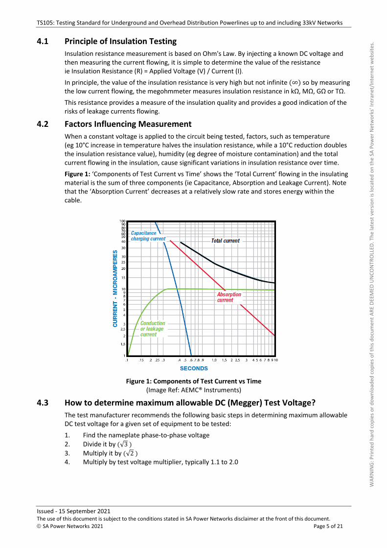
When a constant voltage is applied to the circuit being tested, factors, such as temperature (eg 10°C increase in temperature halves the insulation resistance, while a 10°C reduction doubles the insulation resistance value), humidity (eg degree of moisture contamination) and the total current flowing in the insulation, cause significant variations in insulation resistance over time.
Figure 1: ‘Components of Test Current vs Time’ shows the ‘Total Current’ flowing in the insulating material is the sum of three components (ie Capacitance, Absorption and Leakage Current). Note that the ‘Absorption Current’ decreases at a relatively slow rate and stores energy within the cable.
Figure 1: Components of Test Current vs Time (Image Ref: AEMC® Instruments)
4.3 How to determine maximum allowable DC (Megger) Test Voltage?
The test manufacturer recommends the following basic steps in determining maximum allowable DC test voltage for a given set of equipment to be tested:
1. Find the nameplate phase-to-phase voltage2. Divide it by (√3 )
3. Multiply it by (√2 )
4. Multiply by test voltage multiplier, typically 1.1 to 2.0
WAR
NIN
G: P
rinte
d ha
rd c
opie
s or d
ownl
oade
d co
pies
of t
his d
ocum
ent A
RE D
EEM
ED U
NCO
NTR
OLL
ED. T
he la
test
ver
sion
is lo
cate
d on
the
SA P
ower
Net
wor
ks' I
ntra
net/
Inte
rnet
web
sites
.
TS105: Testing Standard for Underground and Overhead Distribution Powerlines up to and including 33kV Networks
Issued - 15 September 2021 The use of this document is subject to the conditions stated in SA Power Networks disclaimer at the front of this document.
© SA Power Networks 2021 Page 6 of 21
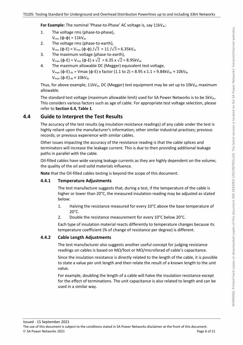
For Example: The nominal ‘Phase-to-Phase’ AC voltage is, say 11kVac:
1. The voltage rms (phase-to-phase), Vrms (φ-φ) = 11kVac
2. The voltage rms (phase-to-earth),
Vrms (φ-E) = Vrms (φ-φ) /√3 = 11 /√3 = 6.35kVac 3. The maximum voltage (phase-to-earth),
Vmax (φ-E) = Vrms (φ-E) x √2 = 6.35 x √2 = 8.95kVac 4. The maximum allowable DC (Megger) equivalent test voltage,
Vmax (φ-E) dc = Vmax (φ-E) x factor (1.1 to 2) = 8.95 x 1.1 = 9.84kVdc ≈ 10kVdc
Vmax (φ-E) dc ≈ 10kVdc
Thus, for above example, 11kVac, DC (Megger) test equipment may be set up to 10kVdc maximum allowable.
The standard test voltage (maximum allowable limit) used for SA Power Networks is to be 5kVdc.
This considers various factors such as age of cable. For appropriate test voltage selection, please refer to Section 6.4, Table 1.
4.4 Guide to Interpret the Test Results
The accuracy of the test results (eg insulation resistance readings) of any cable under the test is highly reliant upon the manufacturer's information; other similar industrial practises; previous records; or previous experience with similar cables.
Other issues impacting the accuracy of the resistance reading is that the cable splices and terminators will increase the leakage current. This is due to then providing additional leakage paths in parallel with the cable.
Oil-filled cables have wide varying leakage currents as they are highly dependent on the volume, the quality of the oil and solid materials influence.
Note that the Oil-filled cables testing is beyond the scope of this document.
4.4.1 Temperature Adjustments
The test manufacture suggests that, during a test, if the temperature of the cable is higher or lower than 20°C, the measured insulation reading may be adjusted as stated below:
1. Halving the resistance measured for every 10°C above the base temperature of 20°C.
2. Double the resistance measurement for every 10°C below 20°C.
Each type of insulation material reacts differently to temperature changes because its temperature coefficient (% of change of resistance per degree) is different.
4.4.2 Cable Length Adjustments
The test manufacturer also suggests another useful concept for judging resistance readings on cables is based on MΩ/foot or MΩ/microfarad of cable’s capacitance.
Since the insulation resistance is directly related to the length of the cable, it is possible to state a value per unit length and then relate the result of a known length to the unit value.
For example, doubling the length of a cable will halve the insulation resistance except for the effect of terminations. The unit capacitance is also related to length and can be used in a similar way.
WAR
NIN
G: P
rinte
d ha
rd c
opie
s or d
ownl
oade
d co
pies
of t
his d
ocum
ent A
RE D
EEM
ED U
NCO
NTR
OLL
ED. T
he la
test
ver
sion
is lo
cate
d on
the
SA P
ower
Net
wor
ks' I
ntra
net/
Inte
rnet
web
sites
.
TS105: Testing Standard for Underground and Overhead Distribution Powerlines up to and including 33kV Networks
Issued - 15 September 2021 The use of this document is subject to the conditions stated in SA Power Networks disclaimer at the front of this document.
© SA Power Networks 2021 Page 7 of 21
5. General Responsibilities SA Power Networks compliance team ensures that all tests specified in this standard are adhered to and will issue ‘Non-Compliance’ where necessary.
The following are the general responsibilities for all parties involved with the testing process.
1. Comply with this technical standard’s requirements. 2. Arrange ‘Network Access Permit’ as per NICC404, prior to commencement of the any test. 3. Execute duty of diligence and comply with relevant regulatory, DIT/Council requirements
and note that SA Power Networks reserves the right to witness any tests carried out by any party.
4. Implement hazard management process (eg risk assessment) and ensure that the safety precautions are in place for all, including public.
5. Commissioning tests on any HV/LV cables are performed without connecting to other equipment/switchgear and ensure that:
(a) All tests are performed on individual sections of the cable. (b) Separate sections of the cable are not connected in series and tested as a whole.
6. Any electrical item to be tested shall be proven dead after isolation, before and after applying main earths by using appropriate tools such as live line indicators, spiking tool, and operating sticks.
6. Testing Requirements
6.1 Network Access Permits
When a Network Access Permit is required, all involved parties shall apply via online Request for Network Access and organise a Network Access Permit well in advance of any test activity and shall comply with the relevant requirements stipulated in NICC404.
6.2 Record and Submit Test Forms
As a part of SA Power Networks Network Management acceptance and sign off to ‘SA Power Networks Full Electrical Infrastructure Works Compliance Form’ (ie TS105 F3) and for issuing the ‘Authority to Proceed Request (ATPR) - For Electrical Contractor’ (ie TS105 F1), is that the Contractor/Constructor is required to supply all the relevant test sheets completed and submitted to the ‘Compliance Coordinator’, as prescribed in TS105A (Forms).
Please refer to Section 3: ‘General Process’ of TS105A (Forms), which provides explanation on how to download, record, and submit the test forms, electronically.
6.3 Emergency/Out of Hours Contact
In emergency and/or out of hours, please call our Faults and Emergencies line on 13 13 66.
W
ARN
ING:
Prin
ted
hard
cop
ies o
r dow
nloa
ded
copi
es o
f thi
s doc
umen
t ARE
DEE
MED
UN
CON
TRO
LLED
. The
late
st v
ersio
n is
loca
ted
on th
e SA
Pow
er N
etw
orks
' Int
rane
t/In
tern
et w
ebsit
es.
TS105: Testing Standard for Underground and Overhead Distribution Powerlines up to and including 33kV Networks
Issued - 15 September 2021 The use of this document is subject to the conditions stated in SA Power Networks disclaimer at the front of this document.
© SA Power Networks 2021 Page 8 of 21
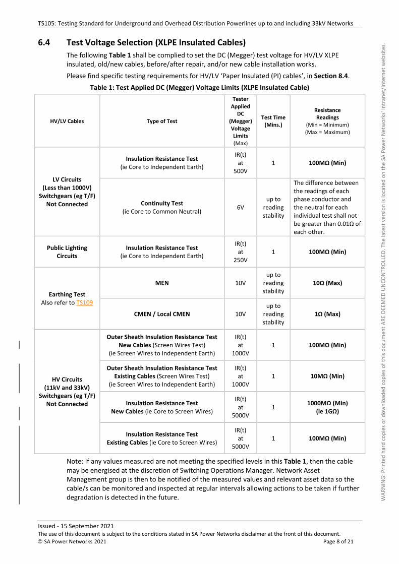
6.4 Test Voltage Selection (XLPE Insulated Cables)
The following Table 1 shall be complied to set the DC (Megger) test voltage for HV/LV XLPE insulated, old/new cables, before/after repair, and/or new cable installation works.
Please find specific testing requirements for HV/LV ‘Paper Insulated (PI) cables’, in Section 8.4.
Table 1: Test Applied DC (Megger) Voltage Limits (XLPE Insulated Cable)
HV/LV Cables Type of Test
Tester Applied
DC (Megger) Voltage Limits (Max)
Test Time (Mins.)
Resistance Readings
(Min = Minimum) (Max = Maximum)
LV Circuits (Less than 1000V)
Switchgears (eg T/F) Not Connected
Insulation Resistance Test (ie Core to Independent Earth)
IR(t) at
500V 1 100MΩ (Min)
Continuity Test (ie Core to Common Neutral)
6V up to
reading stability
The difference between the readings of each phase conductor and the neutral for each individual test shall not be greater than 0.01Ω of each other.
Public Lighting Circuits
Insulation Resistance Test (ie Core to Independent Earth)
IR(t) at
250V 1 100MΩ (Min)
Earthing Test Also refer to TS109
MEN 10V up to
reading stability
10Ω (Max)
CMEN / Local CMEN 10V up to
reading stability
1Ω (Max)
HV Circuits (11kV and 33kV)
Switchgears (eg T/F) Not Connected
Outer Sheath Insulation Resistance Test New Cables (Screen Wires Test)
(ie Screen Wires to Independent Earth)
IR(t) at
1000V 1 100MΩ (Min)
Outer Sheath Insulation Resistance Test Existing Cables (Screen Wires Test)
(ie Screen Wires to Independent Earth)
IR(t) at
1000V 1 10MΩ (Min)
Insulation Resistance Test New Cables (ie Core to Screen Wires)
IR(t) at
5000V 1
1000MΩ (Min) (ie 1GΩ)
Insulation Resistance Test Existing Cables (ie Core to Screen Wires)
IR(t) at
5000V 1 100MΩ (Min)
Note: If any values measured are not meeting the specified levels in this Table 1, then the cable may be energised at the discretion of Switching Operations Manager. Network Asset Management group is then to be notified of the measured values and relevant asset data so the cable/s can be monitored and inspected at regular intervals allowing actions to be taken if further degradation is detected in the future. WAR
NIN
G: P
rinte
d ha
rd c
opie
s or d
ownl
oade
d co
pies
of t
his d
ocum
ent A
RE D
EEM
ED U
NCO
NTR
OLL
ED. T
he la
test
ver
sion
is lo
cate
d on
the
SA P
ower
Net
wor
ks' I
ntra
net/
Inte
rnet
web
sites
.
TS105: Testing Standard for Underground and Overhead Distribution Powerlines up to and including 33kV Networks
Issued - 15 September 2021 The use of this document is subject to the conditions stated in SA Power Networks disclaimer at the front of this document.
© SA Power Networks 2021 Page 9 of 21
6.5 Cable Identification Process
The basis for any numbering sequence for any electrical equipment is to look at the equipment from the kerb and circuit one is on the left side of the equipment and any identification sequence is undertaken in a clockwise direction.
For an example, a three way pillar the incoming LV circuit as shown on the plan on the left side is circuit one, right side circuit is two, and the centre circuit is three. The cable destination needs to also reflect the FINAL destination. Normally, all LV and HV cables have the point of destination clearly labelled at both ends.
Whenever any work is performed on underground cables that are installed in SA Power Networks transformer or switching cubicle, the relevant personnel will undertake the following steps:
1. All cables are to be proved dead and earthed before continuing with the cable phase identification process.
2. Locate the labelling at each end of each cable and note what is recorded on the label:
(a) If the labels match and identify each cable as being the same phase, proceed to step 3, and
(b) If the labels do not match, all cables shall be traced, and the correct identification shall be confirmed.
3. Perform a phase identity test. Refer to Sections 7.2, 8.2 and 9.2. 4. The test results shall be recorded in the relevant forms of TS105A (Forms).
If the cable identification tests are performed as a ‘Request for Network Access Permit’ (RNA) then:
1. The original of the cable identification test results will be supplied to the contractor along with the NAP at the site handover.
2. The cables to be worked on for the period of the contractor’s access will be earthed. 3. It will be the contractor’s responsibility to arrange for earths to be removed and cables
disconnected at both ends for the purpose of cable identification testing; and 4. The contractor shall be present for the site handover of any SA Power Networks assets.
6.6 Cable Testing Process
The relevant personnel will undertake the following cable testing process:
1. All cables are to be proved dead and earthed before continuing with the cable testing process.
2. Perform a HV and LV cables tests as prescribed in Sections 7, 8, 9 and 10. 3. The test results shall be recorded in the relevant forms of TS105A (Forms). 4. If cable test results on the existing cables are unsatisfactory, then the damage to the cables
shall be identified and repaired. The Contractor’s Network Access Permit (NAP) will be withheld until the damaged cables are rectified, then re-issued when satisfactory cable test results are available. Refer to Section 6.7 for more details.
6.7 After the Test - Complete Discharge Requirements
At the end of the test, the equipment’s built-in function displays ‘Zero’ volt, but the ‘Absorption Current’ component does not completely discharge as it needs additional time to be released. Refer to Section 4.2 and be aware of the following notes for the absorption current, that:
1. It acts as an energy absorbed and gets stored in the dielectric materials. 2. It is reversible and has potential to cause a voltage to appear across the cable. This may
happen even after it has been disconnected and/or short-circuited for a time.
Therefore, after the test is completed, ensure that the ‘Absorption Current’ is completely discharged, before any other operation is attempted and adhere to the following requirements:
WAR
NIN
G: P
rinte
d ha
rd c
opie
s or d
ownl
oade
d co
pies
of t
his d
ocum
ent A
RE D
EEM
ED U
NCO
NTR
OLL
ED. T
he la
test
ver
sion
is lo
cate
d on
the
SA P
ower
Net
wor
ks' I
ntra
net/
Inte
rnet
web
sites
.
TS105: Testing Standard for Underground and Overhead Distribution Powerlines up to and including 33kV Networks
Issued - 15 September 2021 The use of this document is subject to the conditions stated in SA Power Networks disclaimer at the front of this document.
© SA Power Networks 2021 Page 10 of 21
1. Always leave the cable grounded for 5 to 10 times as long as the test voltage was applied, ie If the test is conducted for 1min, allow test equipment to arrive at ‘Zero’ volt, and then further discharge the stored charge for 5mins (minimum).
2. Ensure that the discharging devices (eg discharge stick, insulated test lead, grounding stick) are used correctly.
6.8 Non-Compliant Test Results
When acceptable test results are not achieved as specified in this technical standard, then refer to Section 6.4, Table 1 - Note, for further action. Until necessary arrangement is in place, please ensure you do the following:
1. The work site shall be maintained in a safe condition, to protect public/workers from any injuries.
2. Make sure SA Power Networks assets are protected from any damage/vandalise/theft. 3. Where the applicant and their agents have the competency and authorisation, to
identify/rectify the cause of the faulty test result, then they may proceed to rectify fault. 4. Where the applicant and their agents do not have the competency and authorisation to
identify/rectify the cause of the faulty test result, then they shall report the matter to their supervisor and ensure affected persons are advised.
7. Underground LV Cables Testing The old/new LV cables, before or after repair/installation works, shall be tested as stated below:
7.1 Insulation Resistance Test
The LV cables shall be tested for insulation resistance (ie core to independent earth) with an insulation tester at test voltage in accordance with Section 6.4, Table 1.
The minimum insulation resistance to earth or between phases shall in accordance with Section 6.4, Table 1.
The instrument used for this measurement shall have a minimum resolution of 10MΩ on the 0 to 500MΩ range.
At the conclusion of LV insulation resistance testing, the neutrals shall be connected to the earth stakes. For after testing complete discharge requirements, refer to Section 6.6 for more details.
7.2 Phase Identification Test
The correct phasing of all LV circuits shall be checked at all positions where the LV cables are terminated into fuse bases and where any LV cable is run from point to point. This test shall be performed with an instrument designed for the purpose.
Note that mains frequency voltage of 240V is not acceptable for this test. The neutral conductor shall be connected to the earth stake for this test.
7.3 Continuity Test (Resistance of Bolted Connections)
For loop LV UD systems, a continuity (ie core to common neutral) test shall be carried out with an instrument set on ‘Continuity Mode’, on each LV circuit, to ensure that all bolted connections are complete and adequate. The test shall be carried out as follows:
1. At the transformer firmly bond all 4 conductors together. 2. Undertake a continuity test at every point where there is a service provision or open point. 3. In a fused service pillar, the bottom row of fuses bases shall be the point at which the test is
undertaken as that is the furthest extent of the LV network.
The difference between the readings of each phase conductor and the neutral for each individual test shall not be greater than 0.01Ω of each other. Any difference in reading greater than this may indicate a loose or dirty connection and will require further investigation. WAR
NIN
G: P
rinte
d ha
rd c
opie
s or d
ownl
oade
d co
pies
of t
his d
ocum
ent A
RE D
EEM
ED U
NCO
NTR
OLL
ED. T
he la
test
ver
sion
is lo
cate
d on
the
SA P
ower
Net
wor
ks' I
ntra
net/
Inte
rnet
web
sites
.
TS105: Testing Standard for Underground and Overhead Distribution Powerlines up to and including 33kV Networks
Issued - 15 September 2021 The use of this document is subject to the conditions stated in SA Power Networks disclaimer at the front of this document.
© SA Power Networks 2021 Page 11 of 21
The instrument used for this measurement should have a resolution to the second decimal point in the 0 to 5Ω (Ohm) range. A typical instrument would be the earth ‘Megger’ type and considering the resistance values of the test leads.
7.4 Earth Resistance Test
For details on earth resistance test requirements, please refer to TS109.
7.5 Public Lighting Cable Circuits
7.5.1 Polarity Checking
A visual check at each end of public lighting circuits shall be carried prior to connection.
7.5.2 Insulation Resistance Test
The insulation resistance of public lighting circuits, including columns wired on site, shall be tested (ie core to independent earth) with an insulation tester at test voltage in accordance with Section 6.4, Table 1. The minimum insulation resistance to earth or between phases shall be in accordance with Section 6.4, Table 1. The test shall be carried out as follows:
1. The earth and neutral are to be left disconnected at the point of supply. 2. The earth and neutral are to be individually meggered in accordance with Section
6.4, Table 1. 3. The neutral and earth can be bolted up if testing is satisfactory. 4. Check the active by meggering the active back to the point of supply. 5. Check the P/L column and assembly. Apply voltage to the load side of the fuses at
the column in accordance with Section 6.4, Table 1. 6. LED Luminaire shall be tested as per the manufacturer’s instructions. 7. Any variation from the normal consistent readings for the same type of luminaire
indicates a problem in the connection or P/L fitting. 8. On completion the active conductor should be well clear of any metal
components in the column. 9. For after testing complete discharge requirements, refer to Section 6.6 for more
details. 10. The different types and sizes of luminaries have different characteristics. Refer to
TS101 for more details.
8. Underground HV Cables Testing The old/new HV 11kV and 33kV cables including CBD cables, before or after repairs/ installation works, shall be tested individually (ie one phase at a time and one section at a time), as stated below:
8.1 Outer Sheath Insulation Resistance (ie Screen Wire Test)
The purpose of the HV cable ‘Outer Sheath Insulation Resistance Test’ is to determine soundness of the outer cable sheath against water ingress, mechanical damage, termite attack, and so on.
The integrity of the HV cables outer sheath shall be tested (ie each screen wire to independent earth) with an insulation tester at test voltage in accordance with Section 6.4, Table 1, after the cables has been jointed and/or terminated. The minimum screen insulation resistance to independent earth shall be in accordance with Section 6.4, Table 1.
This applies to old/new installation as well as cables before/after repairs. At the conclusion of HV screen wire testing, the neutrals shall be connected to the earth stakes. For after testing complete discharge requirements, refer to Section 6.6 for more details.
Where HV cable circuits are cut and joined to new circuits, sheath testing shall be carried out on the existing old circuit prior to joining to the new cable. WAR
NIN
G: P
rinte
d ha
rd c
opie
s or d
ownl
oade
d co
pies
of t
his d
ocum
ent A
RE D
EEM
ED U
NCO
NTR
OLL
ED. T
he la
test
ver
sion
is lo
cate
d on
the
SA P
ower
Net
wor
ks' I
ntra
net/
Inte
rnet
web
sites
.
TS105: Testing Standard for Underground and Overhead Distribution Powerlines up to and including 33kV Networks
Issued - 15 September 2021 The use of this document is subject to the conditions stated in SA Power Networks disclaimer at the front of this document.
© SA Power Networks 2021 Page 12 of 21
8.2 Phase Identification Test
The correct phasing of all HV circuits shall be checked at all positions where the HV cables have been terminated. This test shall be performed with an instrument designed for the purpose.
Note that mains frequency voltage of 240V is not acceptable for this test. The test may be conducted on either the wire screens or the aluminium conductors. Where the test is performed on the wire screens, they shall be disconnected from earth.
8.3 Insulation Resistance Test
The test voltages for conducting tests on old/new 11kV and 33kV HV cables including CBD cables, before or after repairs/installation works is now limited to 5000Vdc. prior to the performance of this test, the screen wires shall be connected to the permanent earth position.
The HV cable’s core insulation resistance shall be tested (ie each core to screen) with an insulation tester at test voltage in accordance with Section 6.4, Table 1, after the cables has been jointed and/or terminated. The minimum insulation resistance core to screen shall be in accordance with Section 6.4, Table 1.
At the conclusion of HV insulation resistance testing, complete discharge requirements shall be followed as stated in Section 6.6 for more details.
Notes:
1. If further repair works are undertaken, and they require additional joints to be installed, the complete HV testing procedure shall be repeated.
2. Testing at voltages greater than 5000Vdc is not permitted, as DC testing of field aged XLPE cables above 5000Vdc generally increases water tree growth and reduces service life.
3. 5000Vdc is not considered as a ‘HV DC Test’.
8.4 Specific Testing Requirements for Paper Insulated Cables (PI)
Tests on paper insulated cable systems shall be performed after new installations, extensions, or repairs. Many CBD HV cable circuits are connected to older style equipment and therefore test voltages are purposely reduced from those in AS/NZS 1026.
8.4.1 PI - LV Cables: Insulation Resistance Test
For PI - LV cables, the insulation resistance test shall be conducted with a 500Vdc (Megger) for 1 minute. The minimum insulation resistance core to screen shall be 10MΩ to be considered safe to energise.
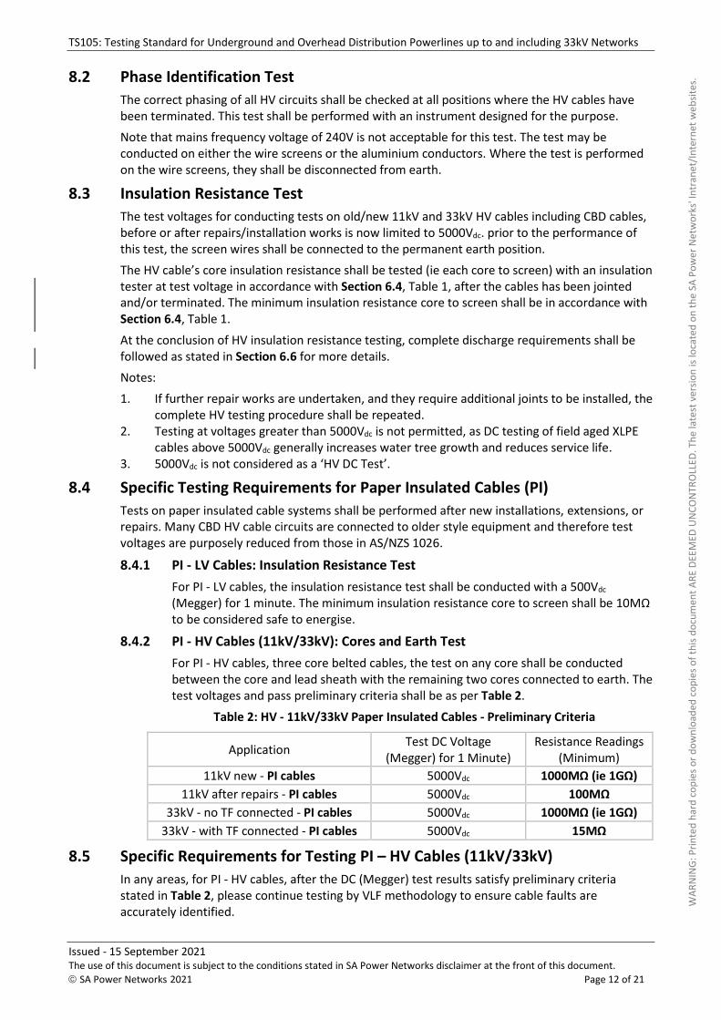
8.4.2 PI - HV Cables (11kV/33kV): Cores and Earth Test
For PI - HV cables, three core belted cables, the test on any core shall be conducted between the core and lead sheath with the remaining two cores connected to earth. The test voltages and pass preliminary criteria shall be as per Table 2.
Table 2: HV - 11kV/33kV Paper Insulated Cables - Preliminary Criteria
Application Test DC Voltage
(Megger) for 1 Minute)
Resistance Readings (Minimum)
11kV new - PI cables 5000Vdc 1000MΩ (ie 1GΩ)
11kV after repairs - PI cables 5000Vdc 100MΩ
33kV - no TF connected - PI cables 5000Vdc 1000MΩ (ie 1GΩ)
33kV - with TF connected - PI cables 5000Vdc 15MΩ
8.5 Specific Requirements for Testing PI – HV Cables (11kV/33kV)
In any areas, for PI - HV cables, after the DC (Megger) test results satisfy preliminary criteria stated in Table 2, please continue testing by VLF methodology to ensure cable faults are accurately identified.
WAR
NIN
G: P
rinte
d ha
rd c
opie
s or d
ownl
oade
d co
pies
of t
his d
ocum
ent A
RE D
EEM
ED U
NCO
NTR
OLL
ED. T
he la
test
ver
sion
is lo
cate
d on
the
SA P
ower
Net
wor
ks' I
ntra
net/
Inte
rnet
web
sites
.
TS105: Testing Standard for Underground and Overhead Distribution Powerlines up to and including 33kV Networks
Issued - 15 September 2021 The use of this document is subject to the conditions stated in SA Power Networks disclaimer at the front of this document.
© SA Power Networks 2021 Page 13 of 21
9. Overhead LV Testing
9.1 ABC - LV - Insulation Resistance Test
LV ABC circuits shall be tested (Meggered) for insulation resistance between cores and earth prior to commissioning to prove safe to energise. Confirm that all working earths have been removed.
Any cores not being tested are to be earthed including the neutral. Ensure neutral bond is still re-connected at the completion of testing. At the conclusion of LV insulation resistance test, complete discharge requirements shall be followed as stated in Section 6.6.
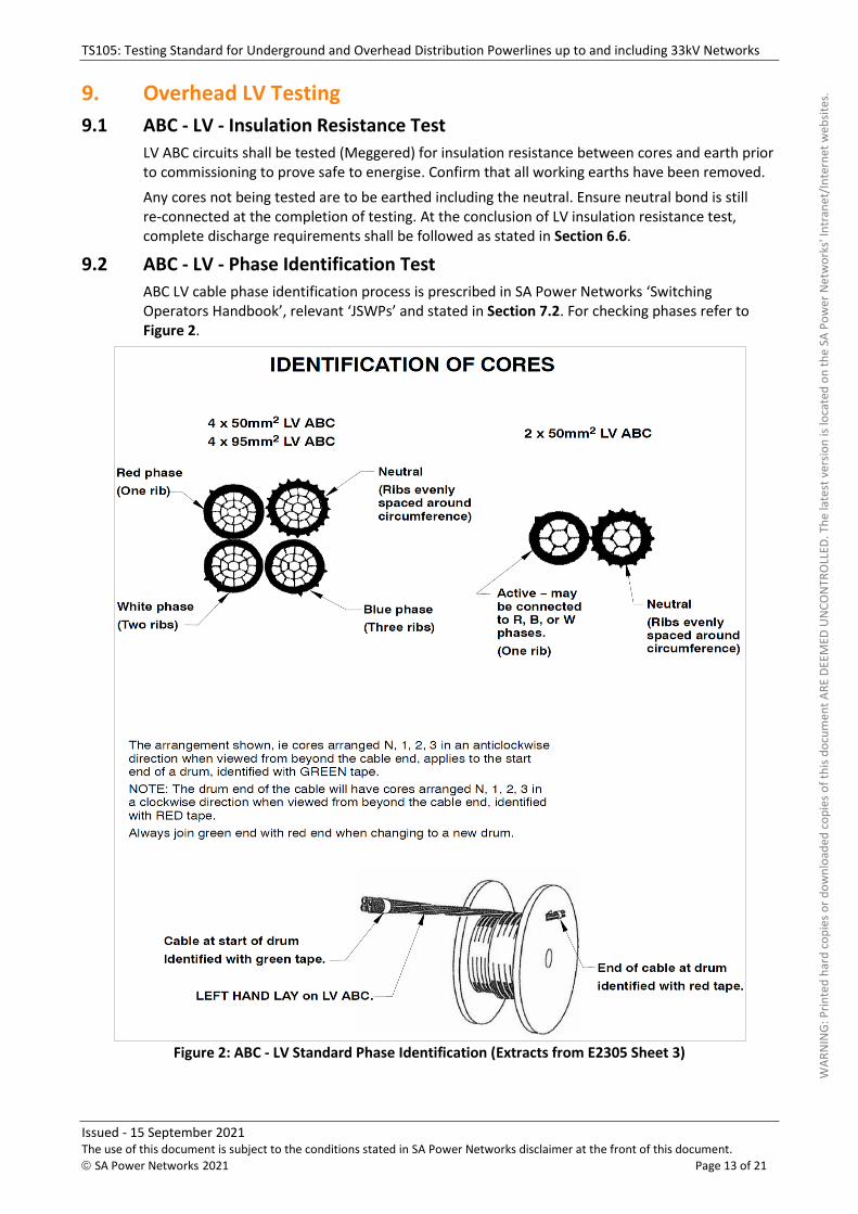
9.2 ABC - LV - Phase Identification Test
ABC LV cable phase identification process is prescribed in SA Power Networks ‘Switching Operators Handbook’, relevant ‘JSWPs’ and stated in Section 7.2. For checking phases refer to Figure 2.
Figure 2: ABC - LV Standard Phase Identification (Extracts from E2305 Sheet 3)
WAR
NIN
G: P
rinte
d ha
rd c
opie
s or d
ownl
oade
d co
pies
of t
his d
ocum
ent A
RE D
EEM
ED U
NCO
NTR
OLL
ED. T
he la
test
ver
sion
is lo
cate
d on
the
SA P
ower
Net
wor
ks' I
ntra
net/
Inte
rnet
web
sites
.
TS105: Testing Standard for Underground and Overhead Distribution Powerlines up to and including 33kV Networks
Issued - 15 September 2021 The use of this document is subject to the conditions stated in SA Power Networks disclaimer at the front of this document.
© SA Power Networks 2021 Page 14 of 21
9.3 ABC - LV - Continuity Test
For ABC LV cable continuity test is not required.
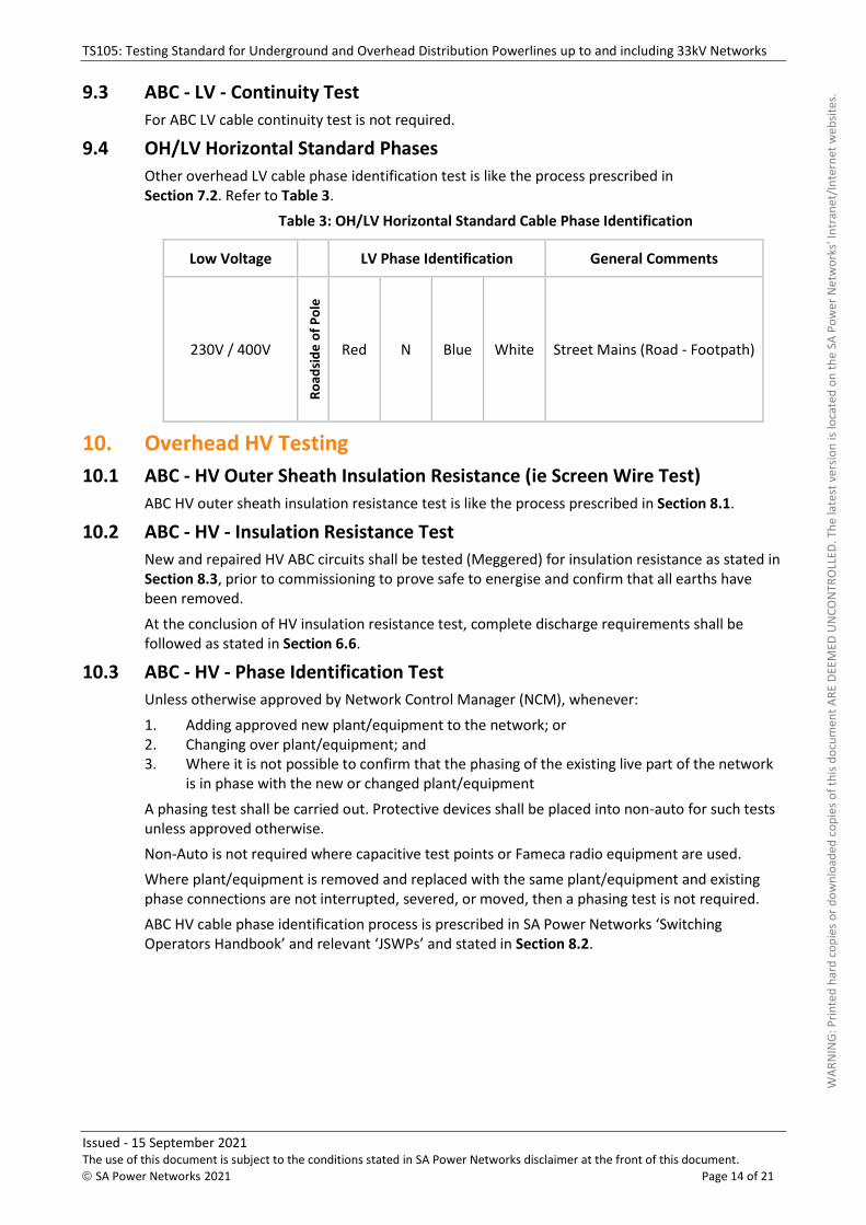
9.4 OH/LV Horizontal Standard Phases
Other overhead LV cable phase identification test is like the process prescribed in Section 7.2. Refer to Table 3.
Table 3: OH/LV Horizontal Standard Cable Phase Identification
Low Voltage LV Phase Identification General Comments
230V / 400V
Ro
adsi
de
of
Po
le
Red N Blue White Street Mains (Road - Footpath)
10. Overhead HV Testing
10.1 ABC - HV Outer Sheath Insulation Resistance (ie Screen Wire Test)
ABC HV outer sheath insulation resistance test is like the process prescribed in Section 8.1.
10.2 ABC - HV - Insulation Resistance Test
New and repaired HV ABC circuits shall be tested (Meggered) for insulation resistance as stated in Section 8.3, prior to commissioning to prove safe to energise and confirm that all earths have been removed.
At the conclusion of HV insulation resistance test, complete discharge requirements shall be followed as stated in Section 6.6.
10.3 ABC - HV - Phase Identification Test
Unless otherwise approved by Network Control Manager (NCM), whenever:
1. Adding approved new plant/equipment to the network; or 2. Changing over plant/equipment; and 3. Where it is not possible to confirm that the phasing of the existing live part of the network
is in phase with the new or changed plant/equipment
A phasing test shall be carried out. Protective devices shall be placed into non-auto for such tests unless approved otherwise.
Non-Auto is not required where capacitive test points or Fameca radio equipment are used.
Where plant/equipment is removed and replaced with the same plant/equipment and existing phase connections are not interrupted, severed, or moved, then a phasing test is not required.
ABC HV cable phase identification process is prescribed in SA Power Networks ‘Switching Operators Handbook’ and relevant ‘JSWPs’ and stated in Section 8.2.
WAR
NIN
G: P
rinte
d ha
rd c
opie
s or d
ownl
oade
d co
pies
of t
his d
ocum
ent A
RE D
EEM
ED U
NCO
NTR
OLL
ED. T
he la
test
ver
sion
is lo
cate
d on
the
SA P
ower
Net
wor
ks' I
ntra
net/
Inte
rnet
web
sites
.
TS105: Testing Standard for Underground and Overhead Distribution Powerlines up to and including 33kV Networks
Issued - 15 September 2021 The use of this document is subject to the conditions stated in SA Power Networks disclaimer at the front of this document.
© SA Power Networks 2021 Page 15 of 21
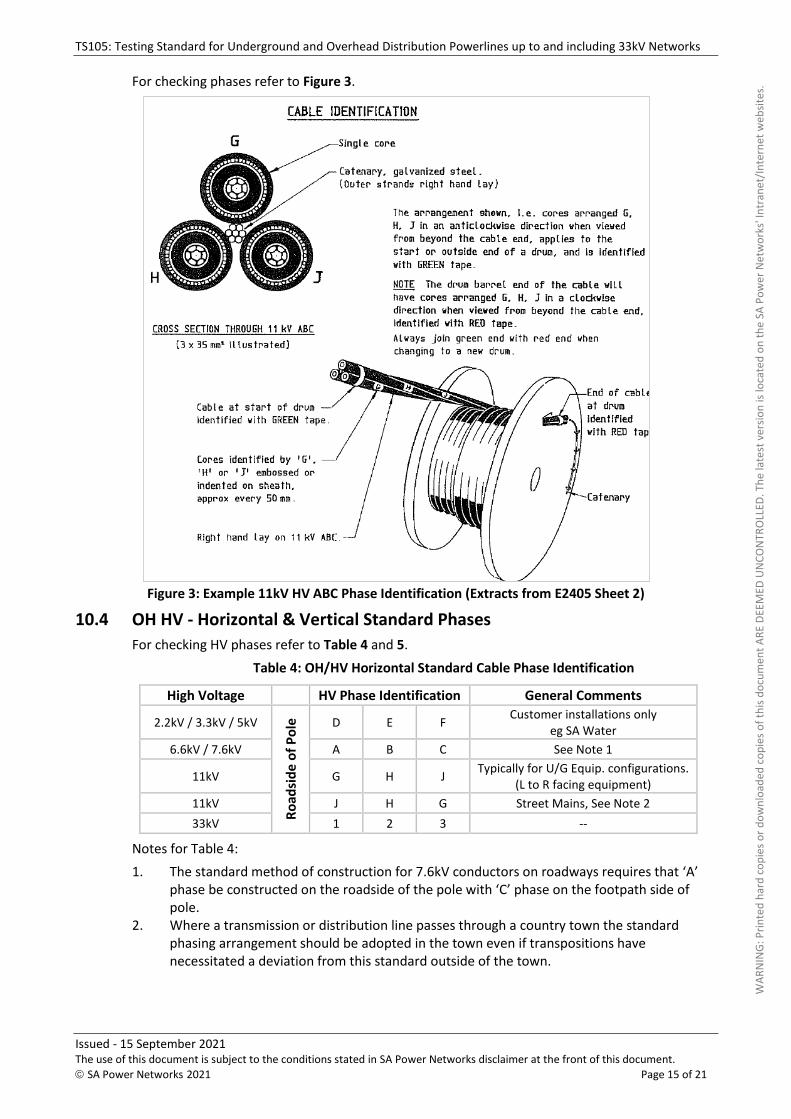
For checking phases refer to Figure 3.
Figure 3: Example 11kV HV ABC Phase Identification (Extracts from E2405 Sheet 2)
10.4 OH HV - Horizontal & Vertical Standard Phases
For checking HV phases refer to Table 4 and 5.
Table 4: OH/HV Horizontal Standard Cable Phase Identification
High Voltage HV Phase Identification General Comments
2.2kV / 3.3kV / 5kV
Ro
adsi
de
of
Po
le
D E F Customer installations only
eg SA Water
6.6kV / 7.6kV A B C See Note 1
11kV G H J Typically for U/G Equip. configurations.
(L to R facing equipment)
11kV J H G Street Mains, See Note 2
33kV 1 2 3 --
Notes for Table 4:
1. The standard method of construction for 7.6kV conductors on roadways requires that ‘A’ phase be constructed on the roadside of the pole with ‘C’ phase on the footpath side of pole.
2. Where a transmission or distribution line passes through a country town the standard phasing arrangement should be adopted in the town even if transpositions have necessitated a deviation from this standard outside of the town.
WAR
NIN
G: P
rinte
d ha
rd c
opie
s or d
ownl
oade
d co
pies
of t
his d
ocum
ent A
RE D
EEM
ED U
NCO
NTR
OLL
ED. T
he la
test
ver
sion
is lo
cate
d on
the
SA P
ower
Net
wor
ks' I
ntra
net/
Inte
rnet
web
sites
.
TS105: Testing Standard for Underground and Overhead Distribution Powerlines up to and including 33kV Networks
Issued - 15 September 2021 The use of this document is subject to the conditions stated in SA Power Networks disclaimer at the front of this document.
© SA Power Networks 2021 Page 16 of 21
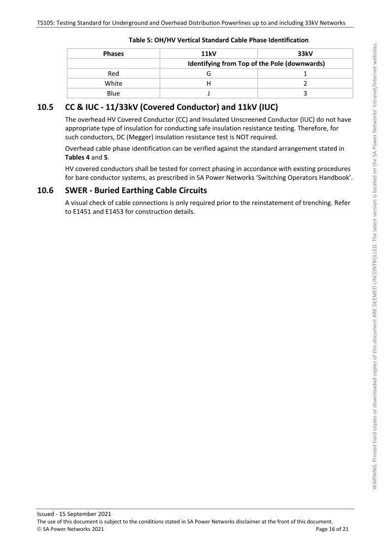
Table 5: OH/HV Vertical Standard Cable Phase Identification
Phases 11kV 33kV
Identifying from Top of the Pole (downwards)
Red G 1
White H 2
Blue J 3
10.5 CC & IUC - 11/33kV (Covered Conductor) and 11kV (IUC)
The overhead HV Covered Conductor (CC) and Insulated Unscreened Conductor (IUC) do not have appropriate type of insulation for conducting safe insulation resistance testing. Therefore, for such conductors, DC (Megger) insulation resistance test is NOT required.
Overhead cable phase identification can be verified against the standard arrangement stated in Tables 4 and 5.
HV covered conductors shall be tested for correct phasing in accordance with existing procedures for bare conductor systems, as prescribed in SA Power Networks ‘Switching Operators Handbook’.
10.6 SWER - Buried Earthing Cable Circuits
A visual check of cable connections is only required prior to the reinstatement of trenching. Refer to E1451 and E1453 for construction details.
WAR
NIN
G: P
rinte
d ha
rd c
opie
s or d
ownl
oade
d co
pies
of t
his d
ocum
ent A
RE D
EEM
ED U
NCO
NTR
OLL
ED. T
he la
test
ver
sion
is lo
cate
d on
the
SA P
ower
Net
wor
ks' I
ntra
net/
Inte
rnet
web
sites
.
TS105: Testing Standard for Underground and Overhead Distribution Powerlines up to and including 33kV Networks
Issued - 15 September 2021 The use of this document is subject to the conditions stated in SA Power Networks disclaimer at the front of this document.
© SA Power Networks 2021 Page 17 of 21
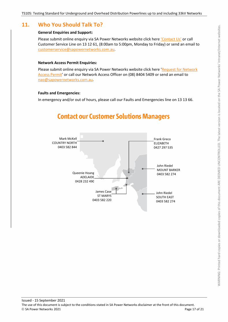
11. Who You Should Talk To? General Enquiries and Support:
Please submit online enquiry via SA Power Networks website click here ‘Contact Us’ or call Customer Service Line on 13 12 61, (8:00am to 5:00pm, Monday to Friday) or send an email to [email protected].
Network Access Permit Enquiries:
Please submit online enquiry via SA Power Networks website click here ‘Request for Network Access Permit’ or call our Network Access Officer on (08) 8404 5409 or send an email to [email protected].
Faults and Emergencies:
In emergency and/or out of hours, please call our Faults and Emergencies line on 13 13 66.
John Riedel MOUNT BARKER 0403 582 274
James Case ST MARYS
0403 582 220
Mark McKell COUNTRY NORTH
0403 582 844
Queenie Hoang ADELAIDE
0428 232 490
John Riedel SOUTH EAST 0403 582 274
Frank Greco ELIZABETH 0427 297 535
WAR
NIN
G: P
rinte
d ha
rd c
opie
s or d
ownl
oade
d co
pies
of t
his d
ocum
ent A
RE D
EEM
ED U
NCO
NTR
OLL
ED. T
he la
test
ver
sion
is lo
cate
d on
the
SA P
ower
Net
wor
ks' I
ntra
net/
Inte
rnet
web
sites
.
TS105: Testing Standard for Underground and Overhead Distribution Powerlines up to and including 33kV Networks
Issued - 15 September 2021 The use of this document is subject to the conditions stated in SA Power Networks disclaimer at the front of this document.
© SA Power Networks 2021 Page 18 of 21
Appendices
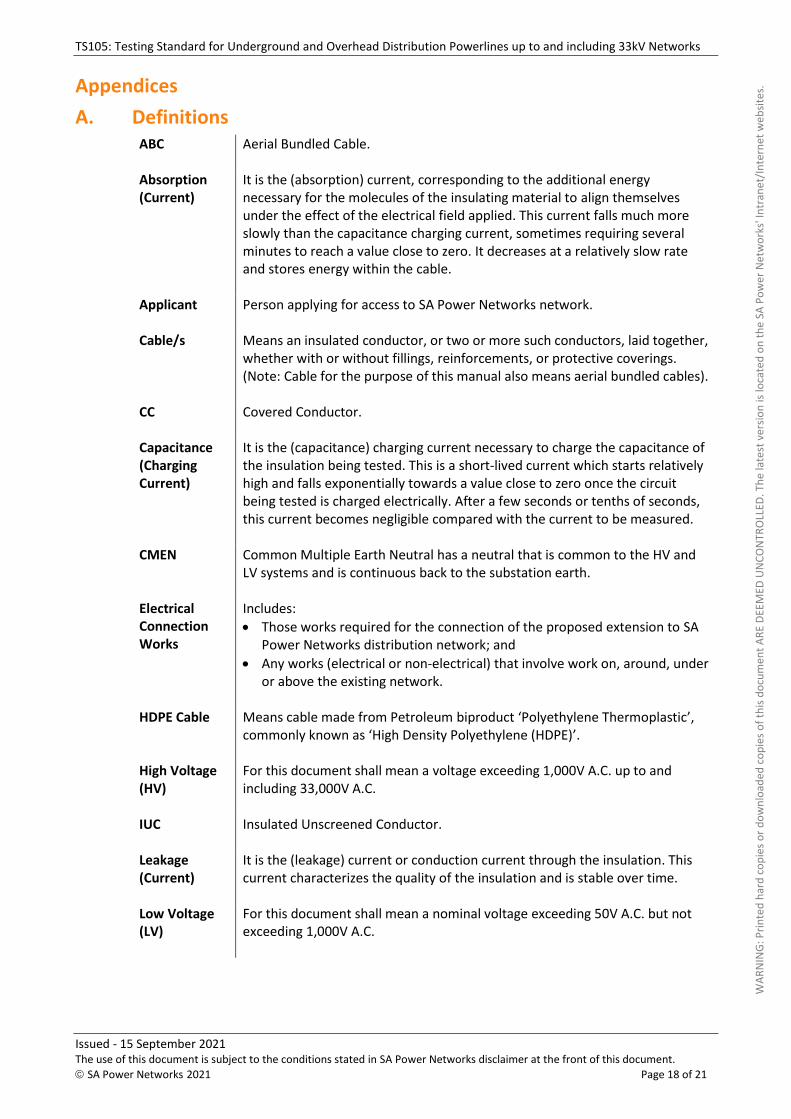
A. DefinitionsABC Aerial Bundled Cable.
Absorption (Current)
It is the (absorption) current, corresponding to the additional energy necessary for the molecules of the insulating material to align themselves under the effect of the electrical field applied. This current falls much more slowly than the capacitance charging current, sometimes requiring several minutes to reach a value close to zero. It decreases at a relatively slow rate and stores energy within the cable.
Applicant Person applying for access to SA Power Networks network.
Cable/s Means an insulated conductor, or two or more such conductors, laid together, whether with or without fillings, reinforcements, or protective coverings. (Note: Cable for the purpose of this manual also means aerial bundled cables).
CC Covered Conductor.
Capacitance (Charging Current)
It is the (capacitance) charging current necessary to charge the capacitance of the insulation being tested. This is a short-lived current which starts relatively high and falls exponentially towards a value close to zero once the circuit being tested is charged electrically. After a few seconds or tenths of seconds, this current becomes negligible compared with the current to be measured.
CMEN Common Multiple Earth Neutral has a neutral that is common to the HV and LV systems and is continuous back to the substation earth.
Electrical Connection Works
Includes:
• Those works required for the connection of the proposed extension to SAPower Networks distribution network; and
• Any works (electrical or non-electrical) that involve work on, around, underor above the existing network.
HDPE Cable Means cable made from Petroleum biproduct ‘Polyethylene Thermoplastic’, commonly known as ‘High Density Polyethylene (HDPE)’.
High Voltage (HV)
For this document shall mean a voltage exceeding 1,000V A.C. up to and including 33,000V A.C.
IUC Insulated Unscreened Conductor.
Leakage (Current)
It is the (leakage) current or conduction current through the insulation. This current characterizes the quality of the insulation and is stable over time.
Low Voltage (LV)
For this document shall mean a nominal voltage exceeding 50V A.C. but not exceeding 1,000V A.C.
WAR
NIN
G: P
rinte
d ha
rd c
opie
s or d
ownl
oade
d co
pies
of t
his d
ocum
ent A
RE D
EEM
ED U
NCO
NTR
OLL
ED. T
he la
test
ver
sion
is lo
cate
d on
the
SA P
ower
Net
wor
ks' I
ntra
net/
Inte
rnet
web
sites
.
TS105: Testing Standard for Underground and Overhead Distribution Powerlines up to and including 33kV Networks
Issued - 15 September 2021 The use of this document is subject to the conditions stated in SA Power Networks disclaimer at the front of this document.
© SA Power Networks 2021 Page 19 of 21
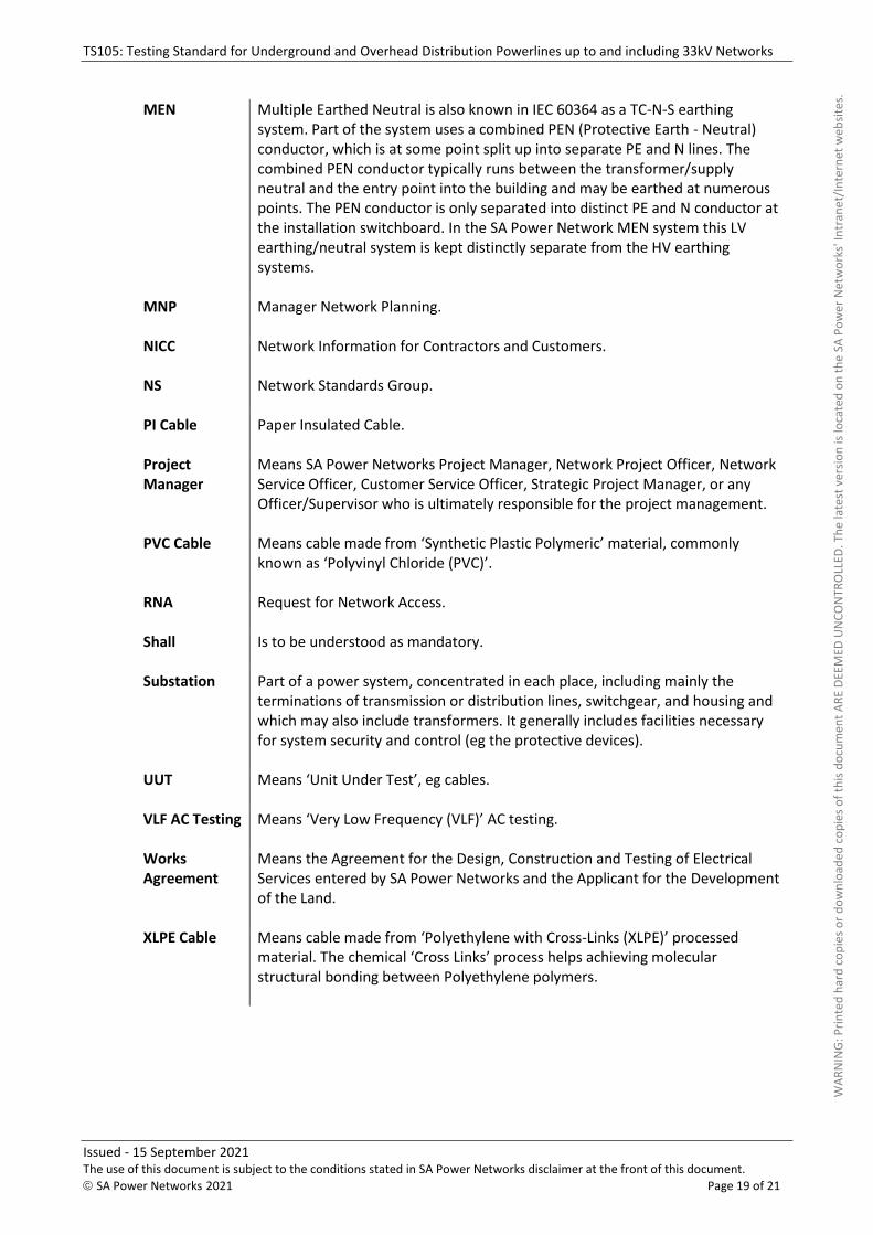
MEN Multiple Earthed Neutral is also known in IEC 60364 as a TC-N-S earthing system. Part of the system uses a combined PEN (Protective Earth - Neutral) conductor, which is at some point split up into separate PE and N lines. The combined PEN conductor typically runs between the transformer/supply neutral and the entry point into the building and may be earthed at numerous points. The PEN conductor is only separated into distinct PE and N conductor at the installation switchboard. In the SA Power Network MEN system this LV earthing/neutral system is kept distinctly separate from the HV earthing systems.
MNP Manager Network Planning.
NICC Network Information for Contractors and Customers.
NS Network Standards Group.
PI Cable Paper Insulated Cable.
Project Manager
Means SA Power Networks Project Manager, Network Project Officer, Network Service Officer, Customer Service Officer, Strategic Project Manager, or any Officer/Supervisor who is ultimately responsible for the project management.
PVC Cable Means cable made from ‘Synthetic Plastic Polymeric’ material, commonly known as ‘Polyvinyl Chloride (PVC)’.
RNA Request for Network Access.
Shall Is to be understood as mandatory.
Substation Part of a power system, concentrated in each place, including mainly the terminations of transmission or distribution lines, switchgear, and housing and which may also include transformers. It generally includes facilities necessary for system security and control (eg the protective devices).
UUT Means ‘Unit Under Test’, eg cables.
VLF AC Testing Means ‘Very Low Frequency (VLF)’ AC testing.
Works Agreement
Means the Agreement for the Design, Construction and Testing of Electrical Services entered by SA Power Networks and the Applicant for the Development of the Land.
XLPE Cable Means cable made from ‘Polyethylene with Cross-Links (XLPE)’ processed material. The chemical ‘Cross Links’ process helps achieving molecular structural bonding between Polyethylene polymers.
WAR
NIN
G: P
rinte
d ha
rd c
opie
s or d
ownl
oade
d co
pies
of t
his d
ocum
ent A
RE D
EEM
ED U
NCO
NTR
OLL
ED. T
he la
test
ver
sion
is lo
cate
d on
the
SA P
ower
Net
wor
ks' I
ntra
net/
Inte
rnet
web
sites
.
TS105: Testing Standard for Underground and Overhead Distribution Powerlines up to and including 33kV Networks
Issued - 15 September 2021 The use of this document is subject to the conditions stated in SA Power Networks disclaimer at the front of this document.
© SA Power Networks 2021 Page 20 of 21
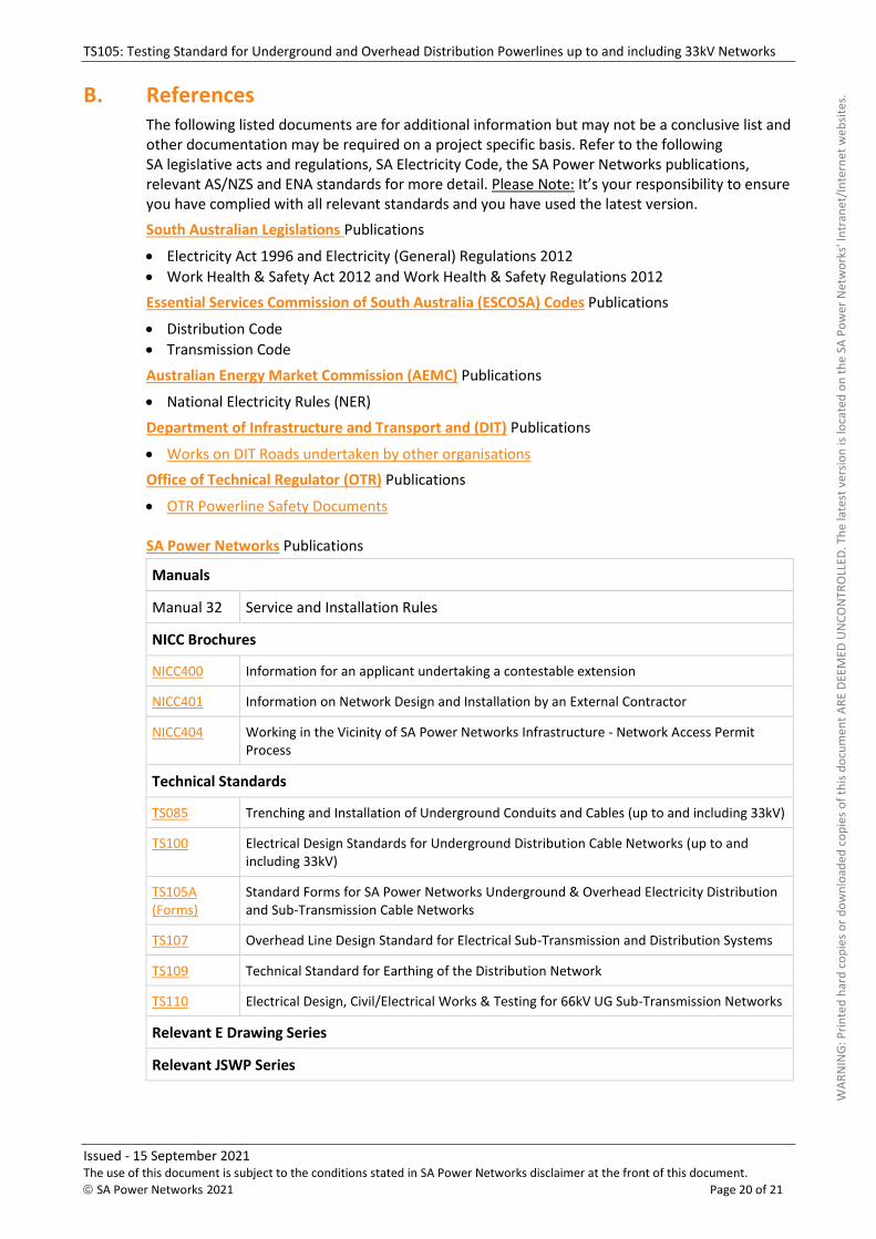
B. References The following listed documents are for additional information but may not be a conclusive list and other documentation may be required on a project specific basis. Refer to the following SA legislative acts and regulations, SA Electricity Code, the SA Power Networks publications, relevant AS/NZS and ENA standards for more detail. Please Note: It’s your responsibility to ensure you have complied with all relevant standards and you have used the latest version.
South Australian Legislations Publications
• Electricity Act 1996 and Electricity (General) Regulations 2012
• Work Health & Safety Act 2012 and Work Health & Safety Regulations 2012
Essential Services Commission of South Australia (ESCOSA) Codes Publications
• Distribution Code
• Transmission Code
Australian Energy Market Commission (AEMC) Publications
• National Electricity Rules (NER)
Department of Infrastructure and Transport and (DIT) Publications
• Works on DIT Roads undertaken by other organisations
Office of Technical Regulator (OTR) Publications
• OTR Powerline Safety Documents
SA Power Networks Publications
Manuals
Manual 32 Service and Installation Rules
NICC Brochures
NICC400 Information for an applicant undertaking a contestable extension
NICC401 Information on Network Design and Installation by an External Contractor
NICC404 Working in the Vicinity of SA Power Networks Infrastructure - Network Access Permit Process
Technical Standards
TS085 Trenching and Installation of Underground Conduits and Cables (up to and including 33kV)
TS100 Electrical Design Standards for Underground Distribution Cable Networks (up to and including 33kV)
TS105A (Forms)
Standard Forms for SA Power Networks Underground & Overhead Electricity Distribution and Sub-Transmission Cable Networks
TS107 Overhead Line Design Standard for Electrical Sub-Transmission and Distribution Systems
TS109 Technical Standard for Earthing of the Distribution Network
TS110 Electrical Design, Civil/Electrical Works & Testing for 66kV UG Sub-Transmission Networks
Relevant E Drawing Series
Relevant JSWP Series
WAR
NIN
G: P
rinte
d ha
rd c
opie
s or d
ownl
oade
d co
pies
of t
his d
ocum
ent A
RE D
EEM
ED U
NCO
NTR
OLL
ED. T
he la
test
ver
sion
is lo
cate
d on
the
SA P
ower
Net
wor
ks' I
ntra
net/
Inte
rnet
web
sites
.
TS105: Testing Standard for Underground and Overhead Distribution Powerlines up to and including 33kV Networks
Issued - 15 September 2021 The use of this document is subject to the conditions stated in SA Power Networks disclaimer at the front of this document.
© SA Power Networks 2021 Page 21 of 21
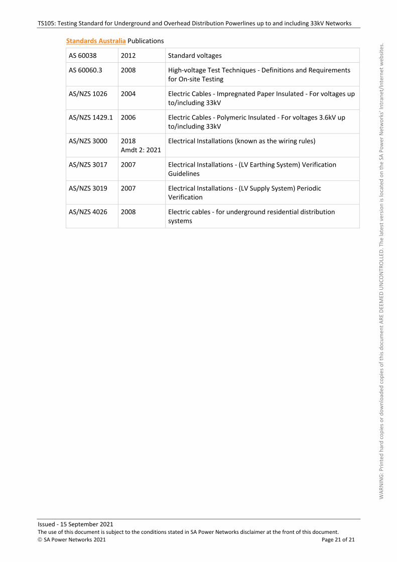
Standards Australia Publications
AS 60038 2012 Standard voltages
AS 60060.3 2008 High-voltage Test Techniques - Definitions and Requirements for On-site Testing
AS/NZS 1026 2004 Electric Cables - Impregnated Paper Insulated - For voltages up to/including 33kV
AS/NZS 1429.1 2006 Electric Cables - Polymeric Insulated - For voltages 3.6kV up to/including 33kV
AS/NZS 3000 2018 Amdt 2: 2021
Electrical Installations (known as the wiring rules)
AS/NZS 3017 2007 Electrical Installations - (LV Earthing System) Verification Guidelines
AS/NZS 3019 2007 Electrical Installations - (LV Supply System) Periodic Verification
AS/NZS 4026 2008 Electric cables - for underground residential distribution systems
WAR
NIN
G: P
rinte
d ha
rd c
opie
s or d
ownl
oade
d co
pies
of t
his d
ocum
ent A
RE D
EEM
ED U
NCO
NTR
OLL
ED. T
he la
test
ver
sion
is lo
cate
d on
the
SA P
ower
Net
wor
ks' I
ntra
net/
Inte
rnet
web
sites
.