Embed Size (px)
Citation preview
March 2017
1 | P a g e
Technical Specifications for Solar
Home System (SHS)
IDCOL Solar Program
Technical Standards Committee
March 2017
March 2017
2 | P a g e
Technical Standards for IDCOL Solar Home System
Program
1. Solar Home System Hardware Description
1.1 The Solar Home System (SHS) is intended to provide the user with a convenient means of
supplying power for small electrical loads such as lights, radio/cassette players or TV. A
typical SHS operates at a rated voltage of 12 Vdc and provides power for fluorescent/LED
luminaries, radio/cassette players, small black and white TV or similar low-power
appliance for about three to five hours a day. Additionally, other types of luminaries, 12
Vdc or lower voltage DC to DC converter outlets or a DC/AC inverter may be supplied as
options. Each SHS consists of one or more photovoltaic (PV) modules, charging a 12 Vdc
battery along with luminaries, related electronic and electrical components and mounting
hardware. In addition to the above, LED TV can be introduced. One fan (not exceeding
15W) can be introduced for systems above 75Wp.
1.2 The system should be designed to have at least two days autonomy (i.e. can run for three
consecutive days without charging from the panel). However three days autonomy can also
be considered.
1.3 The SHS is packaged to provide convenient installation at a remote customer home site by
a qualified technician. The system is constructed such that a user can perform routine
maintenance such as adding battery water and replacing light bulbs and fuses, and a
technician can easily perform system diagnostics or replace components.
2. Certification Requirements
2.1 Products to be used under IDCOL Solar Home System Program (PV Component) must
have a type-test certificate from an accredited testing and certification organization as
elaborated in Annex-1. For local products, a certification from a TSC authorized institution
is acceptable. In case the IDCOL authority feels, they may ask for sample test of any
component from those aforesaid institutions.
2.2 The supplier provides the most appropriate system integration, components, assembly and
packaging that meet all the component specifications in Annex-1: Solar Home System
Component Specifications' and the 'Recommended Practices' described below.
3. Recommended Practices
This section provides a minimum set of requirements that shall be followed in the design,
specification and installation of the qualified SHS. They form a set of “Recommended Practices”
which when followed will ensure adequate levels of safety, performance, reliability and system
lifetime.
March 2017
3 | P a g e
3.1 PV Module Installation
PV module installation refers to the following:
(a) If more than one module is used, identical models shall be used and they shall be
connected in parallel.
(b) For SHS installed permanently on a structure (in contrast with portable units):
i. The modules must ensure waterproof sealing for the solar cells. Modules must be
framed in such a way as to allow secure connection to the module mounting
structure.
ii. The mounting structure will hold the photovoltaic module(s). The module(s) must
be mounted on a support structure made of corrosion resistant material that assures
stable and secure attachment.
iii. The PV array and support structure must be able to withstand wind gusts up to 160
km/hour without damage.
iv. The structure must be mounted at a fixed angle and oriented to maximize the useful
energy supplied to the user over the year (for Bangladesh, the panel should be
facing south with a tilt angle of around 23 degrees with the horizon).
v. The structure will incorporate corrosion resistant hardware for all external
connections.
vi. The modules can be roof or ground-mounted: In case of Roof-mounted modules,
minimum clearance between the PV module and the roofing material must be at
least 20 cm. For pole mounted modules it is recommended that the module
mounting structure be supported on top of a pole of at least 5m height. The
mounting structure must be anchored to the building and not to the roofing
material. For ground-mounted modules, a metal, concrete or treated wood pole
must be used with the modules to be placed at the top of the pole. The modules
must be at least 4 meters off the ground and the pole must be anchored in concrete
or tightly packed soil at least one meter deep in the ground. The pole and mounting
structure must be sufficiently rigid to prevent twisting by the wind or if large birds
alight on the module.
The panel should be mounted clear of vegetation, trees and structure so as to assure that they are
free of shadow throughout day light hours during each season of the year. Furthermore, if more
than one panel is mounted on a support structure the panels should not be mounted such that one
panel will not shade the other module(s).
3.2 Circuit Protection and Charge Controls
Circuit protection and charge controls include the following:
(a) Systems must include a mean to protect users and system components from the
following:
March 2017
4 | P a g e
i. Battery overcharge and excessive water loss.
ii. Battery undercharge and excessive discharge.
iii. Circuit protection against short circuit of any load.
iv. Circuit protection against reverse polarity of module or battery.
v. Circuit protection against internal shorts in charge controller, inverter or other
devices.
vi. Circuit protection against damage by the high PV open circuit voltage when it is
connected to the controller without battery.
vii. Night time discharge of the battery due to reverse current through the module.
(b) Systems will provide appropriate protection by a charge controller incorporating a high
voltage disconnect (HVD), low voltage disconnect (LVD) and circuit protection.
3.3 System Monitoring
System monitoring includes the following:
(a) A display to indicate when the battery is in the charging mode must be provided.
(b) This device must, at a minimum, indicate when the battery condition is:
i. Suitable to operate loads
ii. Energy conservation required
(c) The chosen device must come appropriately labeled such that the user does not have to
refer to a manual to understand the existing battery condition.
3.4 Batteries
Recommended practices for batteries include the following:
(a) Batteries should be selected to offer at least five years of useful life.
(b) The batteries can be supplied in a dry-charged condition and all chemicals and
electrolyte must be supplied in accordance with battery supplier specifications. The
battery and associated containers should be packaged to handle transport down rough
roads.
3.5 Equipment Enclosure
With regard to equipment enclosure, recommended practices comprise the following:
(a) The batteries and charge controller should be kept in properly designed protective
enclosures.
March 2017
5 | P a g e
(b) The batteries must be housed in a vented compartment. All parts of the compartment
subject to battery acid contact must be acid resistant. This compartment must be built
strong enough to accommodate the weight of the battery. Access to the battery
compartment by children must be prevented.
3.6 Wiring
Wiring practices include the following:
(a) Stranded and flexible insulated copper wiring must be used. Sample of wires for the
sub circuits are as follows:
• From PV module to Charge Controller : 2.5 sq. mm/1.5 sq. mm
• From Charge Controller to battery : 4.0 sq. mm
• From Charge Controller to Socket Out-let : 4.0 sq. mm
• From Charge Controller to all other loads : 1.5 sq. mm.
(b) All wiring must be sized to keep line voltage losses to less than 3% including each sub-
circuit and to allow the circuit to operate within the rating of the wire. It is to be noted
that cables used for wiring must have three years of warranty. The cables should be
approved by the technical standards committee (TSC) of IDCOL. The submitted test
report from enlisted testing facilities must have insulation and resistance test results.
(c) For SHS permanently installed on a structure, all exposed wiring (with the possible
exception of the module interconnects) must be in conduits or be firmly fastened to the
building structure. Wiring through roofing, walls and other structures must be
protected through the use of bushings. Wiring through roofing must form a waterproof
seal.
(d) Field-installed wiring must be joined using terminal strips or screw connectors.
Soldering or crimping in the field must be avoided if at all possible. Wire knots are
not allowed. The rated current carrying capacity of the joint must not be less than the
circuit current rating. All connections must be made in junction boxes. Fittings for
lights, switches, and socket outlets may be used as junction boxes where practical.
3.7 Documentation
The component specifications should be summarized by the interested supplier in the form attached
in Annex-2 - Solar Home System Specification Data Sheet along with the required test certificates.
Any exceptions and variations to the specifications must be explicitly stated in a section entitled
Exceptions and Variations in Annex-2. The scope and reasons for each listed exception and
variation must be fully explained with supporting data.
4. User’s Manual
The solar home system (SHS) supplier must provide a User’s Manual intended for the customers
and will be included with each of the packaged systems. The manual must be in Bangla. The User’s
Manual documentation should be simple and easy to understand. Sketches or graphics should be
March 2017
6 | P a g e
used to make the manual easy to understand. The documentation is to include the following:
(a) How the SHS works: battery charging by the array, functions, battery low voltage
protection, and battery overcharge protection. The relationship between energy
available on a daily basis and sunlight conditions should be clearly and simply
explained.
(b) A description of all user interactive hardware including disconnect switches and status
indicators.
(c) Procedures for proper system operation, including a list of load limitations and any
problem loads. These procedures should include suggested operation, including load
conservation during periods of inclement weather, and/or a low voltage disconnect
event. The adverse effect of panel shading and the importance of preventing it must
be explained.
(d) Any user maintenance items.
(e) Emergency shut down procedures and recommendations for extended periods of system
non-use.
(f) A user trouble-shooting guide.
(g) A block diagram showing the main components.
5. Technicians/Technical Manual
The supplier must provide a Technician’s Installation, Operations and Maintenance Manual to be
used by the service technicians. The manual must be in Bangla. The manual will include the
specific details on installation, operation and maintenance, such as:
(a) A detailed technical description of the system.
(b) A complete copy of the User’s Manual.
(c) A complete list of all system components, with associated manufacturers literature,
specifications, and warranties.
(d) Complete installation instructions.
(e) Recommended post-installation acceptance test procedures, including all appropriate
set points and test procedures. They will include:
i. Verification of the installation of the photovoltaic array with regard to position,
direction, inclination and shading avoidance to maximize energy generation.
ii. Test all of the loads for proper operation.
iii. Make system-wide voltage drop measurements in the sub-circuits to verify that
March 2017
7 | P a g e
connections meet the required maximum allowable voltage drop.
iv. Note all measurements in the installation log.
v. Explain to the user the system operating principles, load management requirements,
impact of shading of the array and how to check and avoid it, user maintenance
checks and how to conduct them.
(f) A recommended annual maintenance schedule, with complete maintenance instructions.
(g) A functional block diagram, electrical single-line drawing showing the placement of all
hardware and ratings of all component and physical layout diagram.
(h) Emergency shut down procedures.
6. Packaging and Delivery
6.1 The SHS supplier/PO must obtain the PV system equipment and components, assemble
and wire them into integrated packaged SHS in accordance with the proposed design, and
deliver the packaged SHS to the user.
6.2 Each system must be packaged to prevent any shipping related damage. The supplier/PO
will be responsible for settling any shipping related damaged claims and will be responsible
for replacing damaged systems in a timely manner.
7. Maintenance
The supplier/PO must have the manpower and technical capability to trouble shoot and maintain
the systems installed.
March 2017
8 | P a g e
Annex-1
Solar Home Systems Component Specifications
1. General
1.1 The supplier will provide at a minimum of six-month warranty against manufacturers’
defects on all system-integrated parts and labor excluding fuses or end-use devices such
as luminaries or lamps. On all major individual components, manufacturers’ warranties
will be passed through to the user for IDCOL. Specifically, the PV modules should be
warranted for at least twenty (20) years and must not experience more than 20 percent
of rated capacity reduction in output over its lifetime. The charge controller, switches-
socket and other accessories-appliances should be warranted for at least three years. The
pole mount module supporting structure set with fitting and fixture should be warranted
for 10 years. The battery should be warranted for at least five (5) years. Battery end-of-
life will be determined when the battery capacity down to 1.75 V/cell at 25o C drops to
less than 80 percent of the initial rated capacity. All warranties become effective from
the day the system is accepted by the user for IDCOL. POs will prepare one invoice for
all the equipment sold to the customer and make two copies of that invoice; one to share
with customer and another to preserve for their own office use.
1.2 Nominal system voltage (rated voltage) shall be 12 Vdc.
1.3 The main components should be integrated in such a way as to allow replacement (in
case of failure) with a similarly functioning component of a newer design or a different
brand. This will allow for future component evolution or variability of future
component availability.
1.4. Each of the approved models of the components like solar panel, battery, charge
controller, connecting wires/cables, lamps and LEDs with their inverters/controller
circuits should be tested from IDCOL approved testing agencies every year (as per
IDCOL schedule).
1.5. In case of systems with inverters, pure or quasi sine wave inverters can be allowed. In
addition, efficiency of the inverter should be greater than 90%.
All components, including spares, will undergo full bench testing at the supplier factory or the
originating source factory with proper documentation supplied. All electrical settings (voltages,
current, etc.) will be verified and documented with the results dated and the records maintained at
the suppliers facility.
2. Operating Environment
2.1 PV module should be able to withstand under the climate conditions stated below:-
Particular Description
Climate Tropical, intense sunshine, heavy rain
Maximum Temperature 45oC
March 2017
9 | P a g e
Average isokeraunic level 80 days/yr
Relative Humidity >90%
Average annual rainfall 3000 mm
Maximum wind velocity 160 km/ hour
Altitude As per site
Atmospherical, Mechanical and chemical
impurities
Moderately polluted
Hail storm (Hail size) 25 mm
2.2 All wiring, enclosures, and fixtures that are mounted indoors must be resistant to high
humidity conditions, corrosion, insect, salinity and dust intrusion.
3. Photovoltaic Module
The following are applicable standards for PV modules:
• International Electrotechnical Committee (IEC) 61215: Crystalline Silicon Terrestrial
PV Modules Design Qualification and Type Approval
• IEC 61646: Thin Film Silicon Terrestrial PV Modules Design Qualification and Type
Approval IEC 60904-1: Photovoltaic Devices Part 1 Measurement of PV Current-
Voltage Characteristics
• IEEE 1262: Recommended Practice for Qualification of Photovoltaic Modules
• PV GAP Recommended Standards are preferred.
3.1 The photovoltaic array will consist of one or more flat-plate photovoltaic modules. Each
module should comprise of no less than 36 series-connected single or poly-crystalline
silicon solar cells. Flat plate thin-film modules could also be used.
3.2 The photovoltaic module should have a peak power output of at least 10 Wp.
3.3 All modules must be product tested and certified.
3.4 Each module must be factory equipped with weatherproof junction box with terminal strip
that allows safe and long lasting wiring connection to the module. Where applicable,
protective diodes should be used to avoid the effect of partial shading.
3.5 Each module must be labeled indicating at a minimum: Manufacturer, Model Number,
Serial Number, Peak Watt Rating, Voltage and Current at peak power, Open Circuit
Voltage and Short Circuit Current of each module.
3.6 Every year each model of PV module should be tested locally. Notable that, this will only
be applicable when testing facility exists in Bangladesh and the testing authority is
approved by IDCOL.
3.7 Power tolerance must be positive for each of the PV modules
March 2017
10 | P a g e
Warranty:
A. Two (2) Year Limited PV Module Warranty
PV Modules(s) should be warranted to be free from the defects and/or failures specified below for
a period not exceeding two (2) years from the date of sale to the original customer:
1) Defects and /or failures due to manufacturing;
2) Defects and/or failures due to materials;
3) Cracking of the front glass surface due to foreign objects inside the glass; or
4) Non-conformity with specifications due to faulty manufacturing and/or inspection processes.
If the PV Module(s) fails to conform to this warranty, PV module(s) should be immediately
replaced.
B. Limited Power Output Warranty
Any power loss is due solely to defects in materials or workmanship; IDCOL demands the warranty
of the power output of each type of PV Modules(s) as follows:
20 years (90% / 80%)
IDCOL demands that if, (a) within the first ten (10) years from the date of sale to the Customer,
the PV Modules(s) exhibits a power output of less than ninety percent (90%) of the original
minimum rated power specified at the time of sale, or (b) within twenty (20) years from the date of
less than eighty percent (80%) of the original minimum rated power specified at the time of sale,
manufacturer will repair, fix ( by putting additional panel) or replace the PV Modules(s) at their
own cost or refund the Purchase Price taking into account a yearly depreciation of five percent (5%)
of the panel price. In case of the refund of the depreciated price of the panel, the panel will remain
with the user and company will not take it from him/her. The period of power output warranty for
these replaced modules(s) will be equal to the remaining warranty period of the originally supplied
module(s). Notably, respective POs will be responsible to arrange all the warranty services from
the respective suppliers.
4. Battery Storage
4.1 a) the battery should be 12V block, rechargeable flooded lead-acid battery (Lead-antimony
grid), heavy duty plate construction, deep-cycle, tubular positive plate should include
explosion-proof safety vent, carrying handle. The positive plate must be of tubular type.
4.1 b) Any other type of battery could be accepted if the manufacturer agrees to provide 5 years
of warranty and complies with other issues.
4.2 The maximum permissible self-discharge rate is 5 percent of rated capacity per month at
25°C.
4.3 Cycle life of the battery (i.e., before its residual life drops below 80 percent of the rated AH
capacity), at 25° C must exceed 1500 cycles when discharged down to an average depth of
discharge (DOD) of 70 percent at the discharge rate of 10 hours.
March 2017
11 | P a g e
4.4 The inter-cell connection should not be exposed.
4.5 Size of the battery in AH should not be more than 1.5 times of panel size in Watt peak i.e.
for 50wp panel battery size should not be more than 75Ah.
Warranty:
For batteries of 30 Ah and above, battery capacity will not be less than 90% of the rated for
first two years and will not be less than 80% of the rated for next three years. For batteries
below 30 Ah, the capacity will not be less than 90% of the rated for first year and will not be
less than 80% for the next two years. In case of failure of the battery not performing as per the
specification within the warranty period, the battery should be replaced.
5. Charge Controller & Energy Metering
5.1 Charge controller
5.1.1. The charge controller set points must be factory preset with the set points applicable to
the specified battery characteristics. Charge Controllers should be dust and termite
proof.
5.1.2. The charge controller input current rating has to be greater than 120% of the module's
rated short circuit current.
5.1.3. Maximum current draw of the controller, when no LED’s are lit should not exceed 20
mA and 50 mA with LED.
5.1.4. The model number, serial number, rated voltages and currents, and set points should be
printed on the visible side of the charge controller casing.
5.1.5. Battery, high voltage disconnect 14.3±0.2 volts (for lead acid batteries) (28.6±0.4 volts
for 24V System), or as specified by the manufacturer. Charge controller specifications
must include the type of the battery to be used with it.
5.1.6. Reverse current leakage protection is recommended. Blocking diodes or logic-derived
methods are both acceptable. If blocking diodes are used, they must exhibit a low
forward voltage drop.
5.1.7. The SHS must be protected against damage caused by short circuit at panel terminals
and load terminals when battery is connected to the charge controller, and reverse
polarity of battery or panel connections. Over-current protection must be provided.
Lightning induced surge protection is recommended.
5.1.8. Some means must be provided to safely disconnect the battery and the module during
servicing or repair by a technician.
5.1.9. The load must be controlled by a low voltage disconnect (LVD) device. The LVD must
March 2017
12 | P a g e
be capable of handling at least 150 percent of the maximum expected continuous load
(e.g., assuming all end use devices are simultaneously on). It should be factory preset
to disconnect and reconnect voltages corresponding to the safe operation of the battery
under ambient temperature conditions. For example, for a lead acid battery, a disconnect
voltage of 11.6 Vdc ± 0.1 Vdc (23.2 Vdc ± 0.2 Vdc for 24V System) and reconnect
voltage of 12.6 Vdc ± 0.2 Vdc (25.2 Vdc ± 0.4 Vdc for 24V System) is required.
5.1.10. Each charge controller should be capable of handling at least 120 percent of the rated
current at PV, battery and load terminals for at least for 1 hour without being damaged.
Overload of Charge Controller will be the actual current that exceeds 120% of the rated
current.
5.1.11. Charge Controller should be capable of withstanding 25V (50V for 24V System) at PV
terminal when battery and load is disconnected.
5.1.12. The technical specification of the charge controller must mention the input voltage
range (PV panel side), input current (PV panel side), battery nominal voltage, LVD and
HVD, rated output current (load side).
5.1.13. The panel must have reverse polarity protection, output short circuit and over load
protection.
5.1.14. Efficiency of the charge controller should be at least 90%.
Warranty:
Charge controller or energy meter should be replaced in case of any performance deviation from
the specifications mentioned above over the period of 3 years.
5.2 Energy metering:
Energy metering will be mandatory for 2% of the systems. Each of the POs must keep a track of
their installed systems and use energy meters on 2% of their system installed. DC energy meters,
either to be connected separately or built within the charge controller have to be used. The energy
meters should have non-volatile memory so that the data does not get erased in case of
disconnection from the power source. Both input (on the panel side) and output energy (on the load
side) needs to be metered. Accuracy of the energy meters should be such that inaccuracy in the
readings should be less than 2%.
Warranty:
Energy meter should be replaced in case of any performance deviation from the specifications
mentioned above over the period of 3 years.
6. Fluorescent Lamp Set
Each fluorescent luminary should have its own inverter (ballast).
March 2017
13 | P a g e
6.1. The lamps should have the luminous efficacy of at least 45 lumen/watt over a voltage range
11.4V to 14.4V.
6.2. The inverter electrical efficiency must be greater than 80 percent from 11.4 to 14.4 V when
using the fluorescent lamp specified by the supplier.
6.3. The minimum supply/operating voltage when the tube will strike (start) should be at 11.0V
6.4. Maximum continuous (tested for 1 hour without interruption) operating voltage without
damage to the inverter circuit must be at least 15V.
6.5. The minimum operating frequency should be 20 kHz.
6.6. The electrical waveform at the fluorescent lamp terminals must be symmetrical (the RMS
and average value for each half cycles should not vary by more than 15% measured at
12 V DC, taking RMS value as the base).
6.7. The voltage crest factor (ratio of peak to RMS voltage of the waveform applied to the
fluorescent lamp) must be less than 2.0.
6.8. The input connections to the inverter should prevent the application of voltage with reverse
polarity, or the inverter should be protected against damage when the rated voltage is
applied with reverse polarity.
6.9. Inverter or the luminary must be marked with the manufacturer model number; rated
voltage, wattage and date of manufacture or batch number.
Warranty:
Warranty for a fluorescent lamp will be 1 year.
7. LED Lamp/ Lantern (fixed/movable)
7.1. Minimum power (w) of LED lamp/Lantern should be 1 watt.
7.2. Minimum lumen output of LED Lamp/lantern should be 80 lumen/watt.
7.3. LED should provide minimum 80% of the initial lumen output after 3 years (or 5000 hours
considering the lower value of usage).
7.4. Color of LED light must be white.
7.5. Number of LED cluster in each lamp/lantern should not be more than 12 LEDs/watt. This
issue can be ignored in certain cases.
7.6. Movable lamp/lantern should have built-in rechargeable storage battery of appropriate
capacity. Minimum size of the battery will be 1.5 Ah per wattage of LED lantern.
March 2017
14 | P a g e
7.7 Over the input voltage range of 11.6-14.4 V, input power of the LEDs must not vary by
more than 15% of the rated power.
7.8 Fixed LED lamp/lantern should not be placed at a height more 8 feet from the ground.
7.9 Temperature of the heat sink of the driver circuit of the LED luminaries should be tested
and at still air condition, increase in temperature of the heat sink should not be more
than 20 Degree Celsius after one hour operation.
7.10 LEDs must be permanently engraved with model number in the body.
Warranty:
Warranty for an LED should be 3 years.
8. DC to DC Converter
8.1. The rated input voltage will be determined by the proposed system (like 12V, 24V or
48V etc.) and the rated output voltage should be maintained within the range of 110V-
240V.
8.2. The tolerance of the rated output voltage should be +-5% and must not be lower than
110Volt or higher than 240V.
8.3. The Efficiency of the Converter at rated input voltage and rated load should be 90% or
higher at the ambient temperature condition.
8.4.Self-consumption of the DC-DC converter should be measured in no load
condition at the rated input voltage and should not exceed 25 mA.
8.5.The DC-DC converter must be able to withstand 50% higher voltage (rated
voltage) at the battery terminals.
If the DC-DC converter has built in charge controller:
8.6. The charging side of the converter must follow the LV and HV disconnect and
reconnect voltage range and other specifications of charge controller as per IDCOL
specifications. (As for example, if the battery voltage is 24 or 48 V, all the LV and HV
disconnect or reconnect voltages will be 2 or 4 times respectively corresponding to
12V system).
8.7. On the panel side it should operate within 10% of Maximum Power Point (VMPP to
0.9 VMPP)
8.8. The battery charging efficiency at the rated power of the panel should be equal or
more than 90%.
March 2017
15 | P a g e
8.9. On the panel side, the Charge Controller must be able to withstand a voltage 20%
higher than the open circuit voltage (VOC) of Panel.
Warranty:
Warranty for a DC to DC Converter should be 3 years.
9. Socket Outlet
A 12 Vdc socket outlet for a radio/cassette player, TV or similar appliance must be rated to carry
the maximum expected DC current. The outlet must be protected from reversing the polarity of
the voltage applied to the appliance.
10. General principle for acceptability of a tested component
Any SHS system will have system components like panels, batteries, charge controllers/DC-DC
converter and load components (used by the owner) like lamp, TV, mobile charger etc., it is a
common observation that all the components, when tested, show some degree of deviation from
the rated value mentioned in the specification of the component. Given below, are the guide lines
regarding the acceptability for such components.
In case of system components, individual specifications are to be mentioned and the rating
mentioned in the specification will have to be met quite precisely as the bare minimum. However,
a value higher by 15% will be considered acceptable (except for panel, for panel value higher than
by 15% of the rated can be considered). As for example, a 50Ah battery should show average
capacity of minimum 50Ah. Up to 15% higher value from the rated specification will be acceptable
i.e., a 50Ah battery will be acceptable if the average capacity over charging and discharging is up
to 57.5Ah. This will be the upper limit for acceptance and higher than 57.5Ah will not be
acceptable. Similar will be the case with all the system components as they may have adverse effect
on the designed values of the system component.
In case of the load components, the load must provide the minimum output as specified by the
IDCOL standard. For example, a 4W CFL must produce 4x45 = 180 lumen. If a 4W CFL, when
tested consumes 3.5W but has a good luminous efficacy to produce more than 180 lumens, it will
be considered acceptable. But a load component must not consume power more than 110% of the
rated value, irrespective of its actual output.
March 2017
16 | P a g e
Annex-2
Solar Home System (SHS) Specification Sheet
Photovoltaic Module(s)
(a) Model
number_______________________________________________________________________
(b) Type (a-Si, Mono/Poly Crystalline Si,
etc.)________________________________________________
(c) Number of cells in
series_______________________________________________________________
(d) Open circuit voltage
(Voc)__________________________________________________________V
(e) Short circuit current
(Isc)_____________________________________________________________A
(f) Rated peak power (Pmax) __________________________Wp at STC, (Standard Testing
Conditions)
(g) V
max___________________________________________________________________________
_V
(h) I
max___________________________________________________________________________
__I
(i) NOCT (Nominal Operating Cell Temperature)
_____________________________________deg C
• Short Circuit Current Temp. Co efficient
________________________________________mA/oC
• Open Circuit Voltage Temp. Co efficient
________________________________________mA/oC
March 2017
17 | P a g e
• Frame: The laminate should be fitted with a corrosion and torsion resistant anodised aluminium
frame with extremely high mechanical stability and convenient mounting access.
• JUNCTION Box: Weatherproof, suitable cable entry inlets/outlets, external grounding screw,
+ve and -ve terminal mark, UL/IEC certification.
(j) Test certification
standard______________________________________________________________
(k) Test
laboratory______________________________________________________________________
(Please attach I-V Curve and copy of test certificates, if not supplied already.)
Support Structure (a)
Type______________________________________________________________________(roof
/pole)
(b) Wind velocity withstand capacity
__________________________________________________ km/h
(c)
Material_______________________________________________________________________
_____
Battery Storage (a) Model
number_______________________________________________________________________
(b) Nominal voltage
___________________________________________________________________V
• Battery low voltage
_____________________________________________________________V
• Battery Gassing Voltage
_________________________________________________________V
• Max. Charging Current (Continuous)
_______________________________________________A
• Max. Discharging Current (Continuous)
_____________________________________________A
(c) Structure and material of positive plate
___________________________________________________
(i) Positive plate thickness _____________________________________________________mm
(ii) Negative plate thickness ____________________________________________________mm
March 2017
18 | P a g e
(d) Capacity per battery at C/10 down to 1.75/cell
___________________________________________Ah
(e) Self discharge rate
___________________________________________________________(%/month)
(f) Cycle life down to 75 percent of DOD
___________________________________________________
(g) Electrolyte volume
_______________________________________________________________litres
(h) Certified to standard ______________________________________________ :
___________(Yes/No)
(Please attach I-V Curve, Temp. Effect on Battery and copy of test certificates, if not supplied
already.)
Charge Regulator and Load Control (a) Model number
______________________________________________________________________
(b) Rated voltage
______________________________________________________________________V
(c) High voltage disconnect
(i) Voltage regulation set point (Vr)
____________________________________________________
(ii) Reconnect voltage (Vrr)
___________________________________________________________
(d) Charging indicator?
___________________________________________________________(Yes/No)
• Battery Status___________________________________________________________
• Charging Status __________________________________________________________
• System Connection status ___________________________________________________
• Other (specify)
__________________________________________________________________
(e) Maximum current handling capacity
___________________________________________________A
(f) Type of current leakage protection
______________________________________________________
(g) Voltage drop between module and battery terminals at controller/regulator
_____________________V
March 2017
19 | P a g e
(h) Temperature compensation?
____________________________________________________(Yes/No)
(i) LVD maximum current handling capacity
_______________________________________________A
(j) LVD set points
(i) Disconnect voltage
______________________________________________________________V
(ii) Reconnect voltage
______________________________________________________________V
(k) Current draw with and without LEDs ________________________, mA
_____________________mA
(l) Short circuit protection?
_______________________________________________________(Yes/No)
(m) Reverse polarity protection?
____________________________________________________(Yes/No)
(n) Electronic over current protection
________________________________________________(Yes/No)
(o) Lightening surge protection?
____________________________________________________(Yes/No)
(Please copy of test certificates, if not supplied already.)
System Monitoring (a) Battery State-of-Charge indicator?
_______________________________________________(Yes/No)
(b) Type of indicator
____________________________________________________________________
(c) Indicator settings
(i) Fully charged suitable to use
______________________________________________________V
(ii) Energy conservation
_____________________________________________________________V
(iii) Other (explain)
__________________________________________________________________
Equipment Enclosure (a) Type of battery enclosure
March 2017
20 | P a g e
• Material
________________________________________________________________________
(b) Type of controller housing
_____________________________________________________________
• Material
________________________________________________________________________
(c) Protection method against battery acid/fumes etc.
___________________________________________
Wiring (a) Wire material type
___________________________________________________________________
Wire cross-sections (b) PV module to controller
___________________________________________________________mm2
• Voltage loss factor
____________________________________________________volt/amp/foot
• Insulation type
___________________________________________________________________
(c) Controller to battery
______________________________________________________________mm2
• Voltage loss factor
____________________________________________________volt/amp/foot
• Insulation type
___________________________________________________________________
(d) Controller to
loads_______________________________________________________________ mm2
• Voltage loss factor
____________________________________________________volt/amp/foot
• Insulation type
___________________________________________________________________
Lengths of wired supplied?
_______________________________________________________________
Lighting Fixtures (a) Number of fixtures
___________________________________________________________________
(b) Number of fluorescent (CFL/TFL) lights
_________________________________________________
March 2017
21 | P a g e
For fluorescent lights: (c) Model number(s)
____________________________________________________________________
(d) Wattage(s)
_______________________________________________________________________W
(e) Lumen output(s)
___________________________________________________________________L
(f) Luminous efficacy
_______________________________________________________________L/W
(g) Minimum striking voltage
____________________________________________________________V
(h) Maximum continuous operating voltage
_________________________________________________V
(i) Operating frequency
_____________________________________________________________kHz
(j) Electrical waveform voltage symmetry
___________________________________________________
(k) Maximum crest factor
________________________________________________________________
(l) Open circuit voltage protection?
_________________________________________________(Yes/No)
(Please attach copy of test certificates, if not supplied already.)
Socket Outlet (a) 12 Vdc socket outlet?
_________________________________________________________(Yes/No)
(b) Reverse polarity protection?
____________________________________________________(Yes/No)
(c) 6 and/or 9 V outlet?
___________________________________________________________(Yes/No)
Other Components/Features (a)
______________________________________________________________________________
(b)
______________________________________________________________________________
(c)
_____________________________________________________________________________
(d)
_____________________________________________________________________________
(e)
_____________________________________________________________________________
Exceptions and Variations to the Specifications Taken and Explanations (a)
______________________________________________________________________________
(b)
______________________________________________________________________________
(c)
______________________________________________________________________________
(d)
March 2017
22 | P a g e
______________________________________________________________________________
(e)
______________________________________________________________________________
Annex-3
Terms of Reference
Introduction
International Development Association and Global Environment Facility (GEF) funded Rural
Electrification and Renewable Energy Development (RERED) Project combines rural
electrification and business development. It encompasses the installation of around 64,000 Solar
Home Systems (SHSs) in various modes of use through a number of agents.
The program will be implemented and coordinated by REB and IDCOL and will be executed by
selected Palli Bidyut Samitis (PBSs), Microfinance Institutions (MFIs)/Non-government
Organizations (NGOs), and other private entities.
To determine the technical standards for solar photovoltaic (PV) panels and other hardware
equipment under the REREDP, a Technical Standards Committee (TSC) is to be formed. The
Committee comprises representatives from Bangladesh University of Engineering and Technology
(BUET), Local Government Engineering Department (LGED), REB, and IDCOL (the list of TSC
members is shown in Annex-4).
Objectives
The main objectives of this TSC are:
• Prepare technical specifications for the SHS and renewable energy equipment;
• Set up a database of technical information of products (systems and components) that qualify for
the program;
• Assist manufacturers and suppliers to participate in the program;
• Assist local actors (NGOs, REB) in qualification of manufacturers and suppliers;
• Develop and execute regular sample quality checks on systems installed;
• Keep track of technological and product developments, at least over the period of 4 to 5 years in
which the program is expected to actively purchase products
• Operate on a rather intensive basis during the Phase 1 of the program (February - October 2002),
in which all procedures for procurement will be put in place, including the qualification of
suppliers and their product ranges and during which the first systems will be purchased.
• Convene on an extensive basis during Phase 2 (October 2002 – October 2008) on the basis of 'if-
and-when required'; execute periodical sample tests on newly purchased systems as well as
post-installation monitoring.
March 2017
23 | P a g e
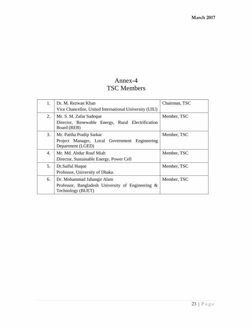
Annex-4
TSC Members
1. Dr. M. Rezwan Khan
Vice Chancellor, United International University (UIU)
Chairman, TSC
2. Mr. S. M. Zafar Sadeque
Director, Renewable Energy, Rural Electrification
Board (REB)
Member, TSC
3. Mr. Partha Pradip Sarkar
Project Manager, Local Government Engineering
Department (LGED)
Member, TSC
4. Mr. Md. Abdur Rouf Miah
Director, Sustainable Energy, Power Cell
Member, TSC
5. Dr.Saiful Huque
Professor, University of Dhaka.
Member, TSC
6. Dr. Mohammad Jahangir Alam
Professor, Bangladesh University of Engineering &
Technology (BUET)
Member, TSC