Embed Size (px)
Citation preview
1
TECHNICAL SPECIFICATIONS
For Construction Of
NATURAL GAS MAINS
AND APPURTENANCES
TOWN OF SMYRNA
NATURAL GAS SYSTEM
RUTHERFORD COUNTY, TENNESSEE
Update
July 18, 2016
2
TOWN OF SMYRNA
NATURAL GAS MAINS
AND APPURTENANCES
TECHNICAL SPECIFICATIONS
TECHNICAL SPECIFICATIONS INDEX PAGE
01010 Project Summary 3
01025 Measurement and Payment 8
01090 Reference Standards 10
01340 Submittals 13
01568 Erosion Control 15
02110 Site Clearing 17
02221 Trenching, Backfilling and Compaction for Utilities 20
02222 Unclassified Excavation for Utilities 27
02485 Seeding 37
02575 Pavement Repair 40
02642 Gas Valves and Appurtenances 41
02714 Gas Lines 48
02830 Fence 64
03303 Concrete for Utility Lines 66
09915 Piping and Equipment Painting 67
3
__ PROJECT SUMMARY
Section 01010 - Page 1 of 5
PART 1 - GENERAL
1.01 SECTION INCLUDES
A. Summary of the Work
B. General Requirements
C. Special Project Procedures
1.02 SUMMARY OF THE WORK
The scope of the work required under this contract, includes furnishing, and paying for all
necessary materials, labor, tools, and other items and constructing a Natural Gas Pipeline
primarily consisting of steel gas line and plastic gas main, and appurtenances complete in
every detail and ready for the Owner’s beneficial use as specified herein, and/or indicated
on the contract drawings listed elsewhere in these specifications. This contract will
consist generally of, but shall not be limited to, the following items:
1. Erosion Control
2. Site grading
3. Concrete work
4. Regulator Station
5. Gas line and appurtenances
6. Testing to include 100% radiographic (x-ray) inspection reports for welds, and
hydrostatic testing
1.03 GENERAL REQUIREMENTS
A. Smoking and Fire Precautions: No smoking, fire, or use of any fire- or explosion-
producing tools or equipment will be permitted on the properties of oil companies or
other concerns prohibiting same on their premises or at any locations where such may
endanger said premises or the current operations thereon.
B. Manufacturers Qualifications: The manufacturers of all materials and equipment used
must be reputable and regularly engaged in the manufacture of the particular material or
equipment for the use and service to which it will be subjected.
C. Contractor Shall Pay for All Laboratory Inspection Service: All materials and equipment
used in the construction of the project shall be subject to adequate inspection and testing
in accordance with accepted standards. The laboratory or inspection agency shall be
selected by the Contractor and approved by the Engineer and/or Owner. Contractor to
4
PROJECT SUMMARY
Section 01010 - Page 2 of 5
pay for all laboratory inspection services as a part of the Contract. Submit all material
test reports to the A/E in triplicate.
D. Compliance With State and Local Laws: Comply with all applicable requirements of
state and local laws and ordinances to the extent that such requirements do not conflict
with federal laws or regulations.
E. Drug Testing: Contractor shall comply with U.S. Department of Transportation Pipeline
Safety Regulation Part 199-Drug Testing. The Contractor shall pay for all testing and
administration services for those individuals who shall be part of this project. The
Contractor and any subcontractors shall comply with this regulation.
F. Operator Qualification: Contractor shall comply with U.S. Department of Transportation
Pipeline Safety Regulation Part 192 – Subpart N Qualification of Pipeline Personnel.
The Contractor shall pay for all testing and administration services for those individuals
who shall be part of this project. The Contractor and any subcontractors shall comply
with this regulation.
G. Protection of Public and Private Property: Take special care in working areas to protect
public and private property. The Contractor shall replace or repair at his own expense
any damaged water pipes, power and communication lines, or other public utilities, roads,
curbs, gutters, sidewalks, drain pipes, ponds or pond structures, sewer drainage ditches,
fences, and all plantings, including grass or sod on the site of the work. Leave the site in
original or better condition after all cleanup work has been done.
H. Markers: Preserve all USGS, TVA, and State of Tennessee, property markers and private
markers; do not remove or disturb any such markers without prior approval from the
Engineer. Any removal and replacement of such markers shall be at the expense of the
Contractor.
I. Non-discrimination: The Contractor agrees to hire qualified persons without regard to
race, creed, color, sex, or national origin for the performance of the work specified in this
contract.
J. Pavement Repair and/or Replacement: Whenever pipe trenches are cut across or along
existing pavement or shoulders, backfill same and restore traffic over the cuts as quickly
as possible by constructing a temporary twelve-inch (12") surface of Class A, grade D
crushed stone. Add material and otherwise maintain such surface until the permanent
pavement is restored or until the entire project is accepted.
K. Department of Transportation Permits: The Owner will secure any permits and provide
bond as required by the Tennessee Department of Transportation for the installation of
permanent facilities on highway rights-of-way. All such work shall be coordinated with
5
PROJECT SUMMARY
Section 01010 - Page 3 of 5
and be subject to the approval of the Department of Transportation, in addition to the
approval of the Engineer.
L. Tunneling or Boring: Where the drawings show that utilities are to be tunneled or bored,
the linear foot amount shown in the Bid Form includes the carrier pipe, casing pipe, and
all other items of work necessary for the line to be completely installed under the railroad
or public roads as shown. The boring shall be accomplished by means of auguring to the
size, line, and grade shown on the drawings.
M. Approved Chemicals: All chemicals used during project construction or furnished for
project operation, whether herbicide, pesticide, disinfectant, polymer, reactant, or of other
classification, must show approval of either EPA or USDA. The use of all such
chemicals and the disposal of residues shall be in strict conformance with instructions.
N. Catalog Data for Owners: Provide duplicate complete, bound sets of a compilation of
catalog data of each manufactured item of mechanical and electrical equipment used in
the work, and present this compilation to the Engineer for transmittal to the Owner before
payment of more than ninety percent (90%) is made. Include descriptive data and printed
installation, operating, and maintenance instructions (including a parts list for each item
of equipment). Provide a complete double index as follows:
1. Listing the products alphabetically by name.
2. Listing alphabetically the names of manufacturers whose products have been
incorporated in the work, together with their addresses and the names and
addresses of the local sales representative.
O. Operation and Maintenance, Instruction to Owner: Where the specifications for specific
equipment require that a factory service representative provide operation and
maintenance instruction to the Owner for that equipment, this service is to be performed
by prior arrangement with the Owner after and in addition to the manufacturer's
instructions to the Contractor for installation and start-up. The individual performing the
instructions to the Owner is to be trained and/or certified by the manufacturer as its
authorized operation, maintenance, and service specialist. If the said specialist is not a
regular full-time employee of the manufacturer, the specialist's qualifications shall be
submitted to the Owner for review and approval prior to scheduling the site visit for
instructions to the Owner.
P. Drawings of Record: Provide a complete, up-to-date record set of blueline prints, which
shall be corrected daily to show every change, and the approved shop drawings. Keep
this set of prints at the job site, and use only as a record set. This shall not be construed
as authorization for the Contractor to make changes in the approved layout without
definite instructions in each case. Turn the set over to the Engineer upon completion of
6
PROJECT SUMMARY
Section 01010 - Page 4 of 5
the project. The Contractor shall, prior to request for final payment, supply the Owner
with a set of as-built drawings of the project. These drawings shall be on Mylar film, or
clear reproducible quality, and shall indicate the location of the gas line and all
appurtenances, and shall include dimensions to the centerline of the pipe and each
appurtenance. The Engineer shall supply the Contractor at the beginning of the project a
set of construction drawings that may be used for modification to create as-built
documents. The drawings shall be delivered to the Engineer and verified before
submittal to the Owner.
Q. Preservation of Existing Vegetation: Take reasonable care during construction to avoid
damage to vegetation. Where the area to be excavated is occupied by trees, brush, or
other uncultivated vegetable growth, clear such growth from the area and dispose of it in
a satisfactory manner. Leave undisturbed any trees, cultivated shrubs, flowers, etc.,
situated within public rights-of-way and/or easements through private property, but not
located directly within excavation limits. Transplant small ornamental trees, cultivated
shrubs, flowers, etc., located directly within excavation limits so they may be replaced
during property restoration operations. Do not remove or disturb any tree larger than six
inches (6") in diameter without the permission of the Engineer. Take special precautions
(including the provision of barricades and the temporary tying back of shrubbery and tree
branches) for the protection and preservation of such objects from all stages of
construction.
The Contractor will be held liable for any damage that may result to said objects from
excavation or construction operations. Trim any limbs or branches of trees broken during
construction operations with a clean cut and paint with an approved tree pruning
compound. Treat tree trunks receiving damage from equipment with a tree dressing.
R. Utilities. The Contractor is to contact the Owner of all underground utilities before
beginning construction in the area. Carefully protect from damage all utilities in the
vicinity of the work at all times. If it is necessary to repair, remove, and/or replace any
such utility in order to complete the work properly, do so in compliance with the rules
and regulations of the particular utility involved. Any such work shall be considered
incidental to the construction or repairs of utility lines, and no additional payment will be
allowed therefor.
The Owner will locate and mark existing water lines and sewer lines, one time prior to
the commencement of work. It shall be the responsibility of the Contractor to maintain
and preserve all stakes and other marks established. If such marks are destroyed by the
Contractor, they shall be replaced by the Owner and be deducted from any amounts that
are due or become due to the Contractor.
7
PROJECT SUMMARY
Section 01010 - Page 5 of 5
1.04 SPECIAL PROJECT PROCEDURES
A. It is intended that rock excavation will be accomplished by means of a rock saw. Blasting
will not be permitted on this project.
B. The contractor will furnish and install all concrete fixtures shown on plans, including but
not limited to pipe support foundations.
PART 2 - PRODUCTS
Not Used
PART 3 - EXECUTION
Not Used
END OF SECTION
8
MEASUREMENT AND PAYMENT
Section 01025 - Page 1 of 2
PART 1 - GENERAL
1.01 SECTION INCLUDES
A. Measurement for payment on a unit price basis shall be as described below. Payment for
each unit installed shall be made according to the unit price bid, as listed in the Bid Form.
Only those items appearing in the Bid Form will be considered for payment on a unit
price basis.
B. Even though an item of work is included in the technical specifications, if it is not both
covered herein and specifically itemized in the Bid Form, payment for it shall not be
separately made. Such work shall be considered a necessary part of or incidental to its
related work.
1.02 SCHEDULE OF PAY ITEMS
Section 01568, Erosion Control
Erosion control is not a pay item. It shall be considered and designated a necessary part of the
construction, and unit prices bid for items with which erosion control is connected shall be full
compensation for this item and for all labor, materials, and equipment required to complete the
item in accordance with the drawings and specifications.
Section 02110, Site Clearing
Site clearing is not a pay item. It shall be considered and designated a necessary part of the
construction, and unit prices bid for items with which site clearing is connected shall be full
compensation for this item and for all labor, materials, and equipment required to complete the
item in accordance with the drawings and specifications.
Section 02222, Unclassified Excavation for Utilities
Unclassified excavation for utilities is not a pay item. It shall be considered and designated a
necessary part of the construction, and unit prices bid for utilities and culverts with which
unclassified excavation is connected shall be full compensation for this item and for all labor,
materials, and equipment required to complete the item in accordance with the drawings and
specifications.
Section 02485, Seeding
Seeding is not a pay item. It shall be considered and designated a necessary part of the
construction, and unit prices bid for items with which seeding is connected shall be full
9
MEASUREMENT AND PAYMENT
Section 01025 - Page 2 of 2
compensation for this item and for all labor, materials, and equipment required to complete the
item in accordance with the drawings and specifications.
Section 02641, Valves
The quantities of valves for which payment will be made shall be the number of each size and
type furnished and installed for 2” or larger. Payment shall be at the unit price for each listed in
the Bid Form and shall include all items incidental to their installation, i.e. valve boxes, treated
timber, concrete, gaskets, flanges, etc.
Section 02642, Appurtenances The regulator station shall be bid based on the drawings. It is the Contractor’s responsibility to
verify the materials list as shown on the plans. Payment shall be at the unit lump sum in the Bid
Form as Item 3 and shall include all items incidental to their installation.
Section 02714, Gas Lines
The quantities of pipe for which payment will be allowed shall be expressed in the unit price
figure for item as listed in Bid Schedule. Such payment shall be full compensation for the
furnishing and installing of pipe, jointing materials (including cut-ins and connections to existing
pipe, excavation, backfill, reaction blocking), and all other work necessary for and incidental to
completion of the work.
Section 02719, Service Assemblies
The quantity of service pipe is not a pay item. This contract will have no service assemblies.
Section 03303, Concrete for Utility Lines
Concrete for pads, pipe supports, cradles, anchors, or thrust blocking is not a pay item and shall
be considered and designated as incidental to construction. Payment for this item of work shall
be included in item as listed in Bid Schedule, Site Work as set forth in the Bid Form.
Section 09915, Piping and Equipment Painting
Piping painting is not a pay item and shall be considered and designated as incidental to
construction. All above ground piping that is exposed, void of fusion bonded epoxy coating,
shall be protected per Section 02714, 2.03 pipe coating and/or this section.
Section 02830, Fencing
Fencing is not a pay item. The labor, materials and installation of temporary and permanent
fencing are to be included in the cost of pay item listed as site work.
END OF SECTION
10
REFERENCE STANDARDS
Section 01090 - Page 1 of 3
PART 1 - GENERAL
1.01 SECTION INCLUDES
A. Abbreviations for reference standards used throughout the Contract Documents.
B. Meet the requirements and recommendations of all Standards, Institutes, Associations,
etc., referred to throughout these documents and specifications as if they were fully
reproduced herein. Unless otherwise noted, the latest editions shall apply.
1.02 ABBREVIATIONS
AAMA - Architectural Aluminum Manufacturer's Association
AASHTO - American Association of State Highway and Transportation Officials
ABMA - American Boiler Manufacturer's Association
ACI - American Concrete Institute
AFBMA - Anti-Friction Bearing Manufacturer's Association
AGA - American Gas Association
AGMA - American Gear Manufacturer's Association
AIA - American Institute of Architects
AIEE - American Institute of Electrical Engineers
AIMA - Acoustical and Insulating Materials Association
AISC - American Institute of Steel Construction
AISI - American Iron and Steel Institute
AITC - American Institute of Timber Construction
AMCA - Air Moving and Conditioning Association
ANSI - American National Standards Institute
APA - American Plywood Association
API - American Petroleum Institute
ARI - Air Conditioning and Refrigeration Institute
ASA - American Standards Association
ASAE - American Society of Automotive Engineers
ASC - Association of Specialty Contractors
ASCII - American Standard Code for Information Interchange
ASHRAE - American Society of Heating, Refrigerating & Air Conditioning Engineers
ASME - American Society of Mechanical Engineers
ASTM - American Society for Testing and Materials
AWI - Architectural Woodwork Institute
AWPB - American Wood Preservers Bureau
AWPI - American Wood Preservers Institute
AWS - American Welding Society
AWWA - American Water Works Association
11
REFERENCE STANDARDS
Section 01090 - Page 2 of 3
BIA - Brick Institute of America
CMAA - Crane Manufacturer's Association of America
CRSI - Concrete Reinforcing Steel Institute
CS - Commercial Standards
CSI - Construction Specifications Institute
EPA - Environmental Protection Agency
FAA - Federal Aviation Administration
FGMA - Flat Glass Marketing Association
FM - Associated Factory Mutual Laboratories
FS - Federal Specifications
IEEE - Institute of Electrical and Electronic Engineers
IRI - Industrial Risk Insurors
ISA - Instrument Society of America
JIC - Joint Industrial Council
MBMA - Metal Building Manufacturers Association
MMA - Monorail Manufacturers Association
NAAMM - National Association of Architectural Metal Manufacturers
NBS - National Bureau of Standards
NEC - National Electrical Code
NEMA - National Electrical Manufacturers Association
NFPA - National Fire Protection Association or National Forest Products Association
NKCA - National Kitchen Cabinet Association
NPT - National Pipe Thread
NRCA - National Roofing Contractors Association
NSF - National Sanitation Foundation
NSWMA - National Solid Waste Manufacturers Association
NWWA - National Woodwork Manufacturing Association
OSHA - Occupational Safety and Health Administration
PPI - Plastic Pipe Institute
RIS - Redwood Inspection Service
SAE - Society of Automotive Engineers
SBCC - Standard Building Code Congress
SDI - Steel Deck Institute
SJI - Steel Joist Institute
SMACNA - Sheet Metal & Air Conditioning Contractors National Association
SPII - Southern Pine Inspection Institute
SSBC - Southern Standard Building Code
SSPC - Steel Structures Painting Council
TCA - Tile Council of America
TIMA - Thermal Insulation Manufacturers Association
UL - Underwriters Laboratories
USG - United States Gypsum
WCLIP - West Coat Lumber Inspection Bureau
WWPA - Western Wood Products Association
12
REFERENCE STANDARDS
Section 01090 - Page 3 of 3
Part 2 - ABBREVIATIONS
Not Used
END OF SECTION
13
SUBMITTALS
Section 01340 - Page 1 of 2
PART 1 - GENERAL
1.01 DELIVER OR MAIL ALL SUBMITTALS TO:
A. Town of Smyrna, Utilities Dept.
315 S Lowry
Smyrna, Tennessee 37167
Telephone: 615-355-5711
Attention: Mark Parker, PE
1.02 WITHIN 30 DAYS OF NOTIFICATION OF SELECTION, SUBMIT:
A. Complete list of proposed subcontractors.
B. Complete list of materials suppliers, including brand names (to be furnished as outlined
in Instructions to Bidders).
C. Complete list of major equipment suppliers, including model numbers for identification.
D. Mill test reports on steel pipe.
1.03 BEFORE BEGINNING ANY ON-SITE CONSTRUCTION, SUBMIT INSURANCE
CERTIFICATES.
1.04 WITHIN 20 DAYS AFTER EXECUTION OF CONTRACT, SUBMIT:
A. Complete construction progress schedule.
B. Schedule of shop drawing submittals.
C. Bid unit price breakdown (schedule of values).
1.05 SUBMIT SHOP DRAWINGS TO MEET THE SCHEDULE OF SHOP DRAWING
SUBMITTALS. SUBMIT 2 COPIES IN ADDITION TO THE NUMBER OF COPIES
TO BE RETURNED BY THE ENGINEER AFTER APPROVAL.
1.06 WITHIN 30 DAYS AFTER EXECUTION OF CONTRACT, SUBMIT:
A. Samples of selection of color of paints.
B. Comparative literature and samples required for architectural product substitutions.
14
SUBMITTALS
Section 01340 - Page 2 of 2
1.07 BEFORE ISSUANCE OF CERTIFICATE OF PAYMENT FOR FINAL PAYMENT,
DELIVER TO THE ENGINEER:
A. Waivers of lien.
B. Written guarantees and warranties.
C. Marked-up record set of drawings showing every alteration or change from the original
drawings and specifications.
D. As-built drawings of project.
E. 24-hour test chart, with pertinent information, name of those responsible, date, media
tested with, time, weather pressure, etc.
F. X-ray test, film, and results with pertinent information, name of those responsible, date,
time, weather, and corresponding drawings that clearly correlate numbered x-rays to
number on drawing.
PART 2 - PRODUCTS
Not Used
PART 3 - EXECUTION
Not Used
END OF SECTION
15
EROSION CONTROL
Section 01568 - Page 1 of 2
PART 1 - GENERAL
1.01 SECTION INCLUDES
A. This work shall consist of erosion control on all cut and fill operations, excavation,
backfill, or other construction activities within the limits of the construction site, within
any temporary or permanent easements, and within any borrow site used during the
period of construction. The protection of these sites shall continue throughout the
construction period. During flood seasons, protect the sites by sandbagging, the pumping
of water, and any other means appropriate to restrain flooding of plant and equipment.
During dry weather, sprinkle the site with water or use other means as necessary to
provide dust control. In case of abnormally cold weather, any construction such as
excavation work may be delayed until warmer weather or covered to prevent freezing.
B. All work, at a minimum, to conform to the State of Tennessee, Department of
Environment and Conservation current specifications.
PART 2 - PRODUCTS
2.01 GRASS SEED
A. Temporarily stabilize areas from which topsoil has been removed and topsoil stockpiles
by seeding fast growing annuals such as cereal, rye, annual rye grass, sudan grass, and
millet that provide quick protection. These annual grasses are to be seed certified by the
State Department of Agriculture and can be worked into the soil when the site is prepared
for final seeding of more permanent species. Use commercial lime and fertilizer on
exposed areas subject to severe erosion.
PART 3 - EXECUTION
3.01 CONSTRUCTION AND EXCAVATION
A. Conduct construction so as to provide the site with maximum protection from erosion at
all times.
B. Conduct excavation activities to provide erosion and sediment control as follows:
1. Do not start clearing and excavation until a firm construction schedule is
submitted to and approved by the Engineer. Continuously coordinate the
schedule with the clearing and excavation activity.
2. In streets and other paved areas, remove excavated material from the site as
construction progresses to prevent any erosion of this material.
16
EROSION CONTROL
Section 01568 - Page 2 of 2
3. In other areas, place the excavated material so as not to block any drainage area.
Replace this excavated material in the trench immediately after repairs have been
completed and are approved by the Owner.
4. Retain natural vegetation whenever feasible.
5. Restore and cover exposed areas subject to erosion as quickly as possible by
means of seeding and mulching. Use diversion ditches or other methods as
appropriate to prevent storm water from running over the exposed area until
seeding is established as specified.
6. Take particular care along streams and drainage ditches so that fallen trees, debris,
and excavated material will not adversely affect the streamflow. Exercise care to
minimize the destruction of stream banks. Wherever the stream banks are
affected by construction, reduce the slope of the stream banks to provide a
suitable condition for vegetative protection. Minimize land exposure in terms of
area and time.
7. Cover exposed excavated areas with mulch or vegetation.
8. Mechanically retard the rate of runoff water.
9. Trap the sediment contained in the runoff water.
10. Divert water from erosive areas.
11. Take care during the pouring of concrete, hauling of materials, etc., to keep
vehicles from creating a severe erosion problem. Proper scheduling of operations
and prompt repair of ruts created during this operations is necessary from this
source.
12. Control dust by sprinkling or other means as necessary to keep it to a minimum.
13. Pave or otherwise stabilize roadways and driveways as soon as feasible.
C. Re-grade and re-seed surfaces eroded or otherwise damaged during any and all
construction operations as necessary.
END OF SECTION
17
SITE CLEARING
Section 02110 - Page 1 of 3
PART 1 - GENERAL
1.01 SECTION INCLUDES
A. This work consists of clearing, grubbing, removing, and disposing of all debris and of all
vegetation, buildings, and foundations not removed by others that are within designated
construction areas, except for such objects that the Engineer designates to remain. The
work shall also include preserving and protecting from injury or defacement all
vegetation and objects designated to remain.
1.02 JOB CONDITIONS
A. Traffic: Conduct site clearing operations to ensure minimum interference with roads,
streets, walks, and other adjacent occupied or used facilities. Do not close or obstruct
streets, walks, or other occupied or used facilities without permission from authorities
having jurisdiction.
B. Protection of Existing Improvements: Provide protection necessary to prevent damage to
existing improvements indicated to remain in place.
1. Protect improvements on adjoining properties and on Owner's property.
Particular to this contract, Contractor to protect existing utilities on site, including
but not limited to water pumping station, electric transformer, site improvements
including fencing and pavement, overhead and underground utilities, etc.
2. Restore damaged improvements to their original condition, as acceptable to
parties having jurisdiction.
C. Protection of Existing Trees and Vegetation: Protect existing trees and other vegetation
indicated to remain in place against unnecessary cutting, breaking or skinning of roots,
skinning and bruising of bark, smothering of trees by stockpiling construction materials
or excavated materials within drip line, excess foot or vehicular traffic, or parking of
vehicles within drip line. Provide temporary guards to protect trees and vegetation to be
left standing.
1. Water trees and other vegetation to remain within limits of contract work as
required to maintain their health during the course of construction operations.
2. Provide protection for roots over 1-1/2 inches in diameter cut during construction
operations. Coat cut faces with emulsified asphalt, or other acceptable coating,
formulated for use on damaged plant tissues. Temporarily cover exposed roots
with wet burlap to prevent roots from drying out. Cover with earth as soon as
possible.
18
SITE CLEARING
Section 02110 - Page 2 of 3
3. Repair or replace trees and vegetation indicated to remain which are damaged by
construction operations in a manner acceptable to Engineer. Employ licensed
arborist to repair damages to trees and shrubs.
D. Improvements on Adjoining Property: Authority for performing removal and alteration
work on property adjoining Owner's property will be obtained by Owner prior to award
of contract.
1. Extent of work on adjacent property is indicated on Drawings.
E. Protect existing utility service from damage. Location of existing utilities shall be
verified by Contractor prior to commencing work.
PART 2 - PRODUCTS
2.01 MATERIALS
Not applicable to work of this section.
PART 3 - EXECUTION
3.01 SITE CLEARING
A. General: Remove trees, shrubs, grass, other vegetation, improvements, or obstructions
interfering with installation of new construction. Remove such items elsewhere on site or
premises as specifically indicated. Removal includes digging out stumps and roots.
B. Carefully and cleanly cut roots and branches of trees indicated to be left standing where
such roots and branches obstruct new construction.
C. Topsoil: Topsoil is defined as friable clay loam surface soil. Satisfactory topsoil is
reasonably free of subsoil, clay lumps, stones, and other objects over two inches (2") in
diameter and without weeds, roots, and other objectionable material.
1. Strip topsoil to whatever depths encountered in a manner to prevent intermingling
with underlying subsoil or other objectionable material.
2. Remove heavy growths of grass from areas before stripping.
3. Stockpile topsoil in storage piles in areas shown or where directed. Construct
storage piles to freely drain surface water. Cover storage piles, if required, to
prevent wind-blown dust.
D. Clearing and Grubbing: Clear site of trees, shrubs, and other vegetation except for those
indicated to be left standing.
19
SITE CLEARING
Section 02110 - Page 3 of 3
1. Completely remove stumps, roots, and other debris protruding through ground
surface.
2. Fill depressions caused by clearing and grubbing operations with satisfactory soil
material unless further excavation or earthwork is indicated.
3.02 DISPOSAL OF WASTE MATERIALS
A. Burning is not permitted on Owner's property.
B. Remove waste materials and unsuitable and excess topsoil from Owner's property and
dispose of off site in a legal manner.
END OF SECTION
20
TRENCHING, BACKFILLING, AND COMPACTION FOR UTILITIES
Section 02221 - Page 1 of 7
PART 1 GENERAL
1.01 REQUIREMENTS INCLUDED
A. Excavation for piped utility material.
B. Provide necessary sheeting, shoring and bracing.
C. Prepare trench bottom with appropriate materials.
D. Dewater excavation as required.
E. Place and compact granular beds, as required, and backfill.
1.02 RELATED WORK
A. Section 02110: Clearing.
B. Section 02210: Site Grading.
C. Section 03300: Cast-In-Place Concrete.
1.03 PRECAUTIONS
A. Notify utility companies when necessary to disturb existing facilities and abide by their
requirements for repairing and replacing.
B. Protect all vegetation and other features to remain.
C. Protect all benchmarks and survey points.
PART 2 PRODUCTS
2.01 BEDDING AND BACKFILL MATERIALS - STORM SEWERS
A. Class A Material: Continuous concrete cradle constructed in conformity with details
shown on drawings, consisting of Class “B” concrete as specified in Section 03300.
B. Class B Material: Sand or a natural sandy soil, all passing a 3/8” sieve with not more
than 10% passing a No. 200 sieve; or stone, gravel, chert or slag of Gradation C or D of
Tennessee Department of Transportation Specifications (TDOT Specs).
21
TRENCHING, BACKFILLING, AND COMPACTION FOR UTILITIES
Section 02221 - Page 2 of 7
C. Class C Material: Natural ground or compacted embankment at a depth of at least 10%
of the outside vertical pipe diameter.
D. In rock cuts or other areas where free drainage bedding or backfill materials are required
use crushed stone, slag or washed gravel of size ¼” or limestone dust.
PART 3 EXECUTION
3.01 PREPARATION
A. Install barriers and other devices to protect areas adjacent to construction.
B. Protect and maintain all benchmarks and other survey points.
3.02 EXCAVATION TRENCHES
A. Perform in such a manner as to form a suitable trench in which to place the pipe and so as
to cause the least inconvenience to the public.
B. Maximum width at the crown of the pipe - 2 feet plus the nominal diameter of the pipe.
C. Cut pavement along neat, straight lines with either a pavement breaker or pavement saw.
D. Trench depth - sufficient to provide minimum cover of 30 inches over the top of the pipe.
E. Align trench as shown on the drawings unless a change is necessary to miss an
unforeseen obstruction.
F. Shape the bottom of the trench to provide uniform bearing of the pipe on undisturbed
earth throughout its entire length.
G. Fill the bottom of the trench with granular material as specified herein.
H. When unstable soil is encountered at the trench bottom, remove it to a depth required to
assure support of the pipeline and backfill to the proper grade with coarse aggregate
AASHTO M-43, Size No. 2 or 3.
I. Remove rock encountered in trench excavation to a depth of 6 inches below the bottom
of the pipe barrel, backfill with an approved material, and compact to uniformly support
the pipe. In no case shall solid rock exist within six (6) inches of the finished pipeline.
22
TRENCHING, BACKFILLING, AND COMPACTION FOR UTILITIES
Section 02221 - Page 3 of 7
3.03 SHEETING, SHORING AND BRACING
A. When necessary, furnish, put in place, and maintain such sheeting, bracing, etc., as may
be required to support the sides of the excavation and to prevent movement.
B. Take care to prevent voids outside the sheeting.
C. If voids are formed, immediately fill and ram to the satisfaction of the engineer.
D. Unless adjacent facilities will be injured, remove all sheeting, shoring, and bracing after
backfill has been placed to a depth of 18 inches over the pipeline.
E. Cut shoring off at the top of the pipe and leave the lower section in the trench.
3.04 USE OF EXPLOSIVES
A. Conduct all blasting operations in accordance with prevailing municipal, state or other
agency regulations, codes, ordinances, or laws.
B. Exercise due caution when blasting adjacent to existing structures and pipelines.
C. If structures or pipelines are damaged, promptly replace or repair them at no expense to
Owner or Engineer.
D. Do not conduct blasting operations within 25 feet of water, sewer, gas or other utility
lines.
E. Cover all shots with blasting mats to prevent flying material.
3.05 DISPOSAL OF EXCAVATED MATERIAL
Satisfactorily dispose of all excess material that cannot be used for or is not suitable for
embankments.
3.06 UNAUTHORIZED EXCAVATION
A. All excavation outside or below the proposed lines and grades shown on the drawings.
B. Backfill areas of unauthorized excavation with the type material necessary (earth, rock or
concrete) to insure the stability of the structure of construction involved.
C. Unauthorized excavation or backfill to replace same shall not be a pay item.
23
TRENCHING, BACKFILLING, AND COMPACTION FOR UTILITIES
Section 02221 - Page 4 of 7
3.07 REMOVAL OF WATER
A. Keep excavated areas free of water while work is in progress.
B. Well-pointing shall be performed if required.
C. Take particular precautions to prevent the displacement of structures or pipelines as a
result of accumulated water.
3.08 OBSTRUCTIONS
A. Obstructions shown on the drawings are for information only and do not guarantee their
exact locations nor that other obstructions are not present.
B. When utilities or obstructions are not shown on the drawings but are present off the
roadway at the location of the proposed pipeline route, the contractor may request to
relocate the pipeline in the roadway if necessary to avoid disturbing the utility or
obstructions.
C. If the relocation is approved, the Contractor shall receive compensation for additional
granular backfill and pavement replacement.
D. Exercise due care in excavating adjacent to existing obstructions and do not disturb same
unless absolutely necessary.
E. In the event obstructions are disturbed, repair or replace as quickly as possible to the
condition existing prior to their disturbance. This repair or replacement will not be a pay
item.
F. If desired by the utility company, pay for the repair or replacement work performed by
the forces of the utility company or other appropriate party.
G. If replacement or repair of disturbed obstructions is not performed after a reasonable
period of time, the owner may have the necessary work done and deduct the cost of same
from payments to the contractor.
3.09 EFFLUENT PIPE BEDDING
A. Use Class A, B, or C bedding, whichever is shown on the drawings. If not shown, use
Class C bedding.
B. Construct Class B bedding in a trench cut in natural ground or compacted embankment.

24
TRENCHING, BACKFILLING, AND COMPACTION FOR UTILITIES
Section 02221 - Page 5 of 7
1. Bed pipe on 6” of Class B material and sufficient additional Class B material
accurately shaped by a template to fit the lower part of the pipe exterior.
2. Ram and tamp in layers not over 6”, in loose thickness, around the pipe to a
minimum depth of that shown on the drawings.
3. When bell and spigot pipe is to be placed, dig recesses in the bedding material of
sufficient width and depth to accommodate the bell.
C. Construction Class C bedding in a shallow trench.
1. Shape the bedding to fit the lower pipe exterior for the specified embedment.
2. When bell and spigot pipe is to be placed, dig recesses of sufficient width and
depth to accommodate the bell.
3.10 BEDDING FOR GAS LINES
A. Bed in a trench cut in natural ground.
B. Assure uniform support throughout the entire length of pipe.
C. Excavate the trench in such a manner as to form a suitable bed on which to place the
pipe.
3.11 INITIAL BACKFILLING
A. Do not begin backfilling before the engineer has inspected the grade and alignment of the
pipe, the bedding of the pipe, and the joints between the pipe. If backfill material is
placed over the pipe before an inspection is made, reopen the trench in order for an
inspection to be made.
B. Perform backfilling by hand, together with tamping, until fill has progressed to 18” above
the top of the pipe.
1. Deposit Class 1 angular material (where required) or loose soil from lumps, clods,
frozen material or stones in layers approximately 6” thick.
2. Compact by hand, or with manually operated machine tampers actuated by
compressed air or other suitable means.
3. Use tamps and machines of a suitably type which do not crush or otherwise
damage the pipe.
25
TRENCHING, BACKFILLING, AND COMPACTION FOR UTILITIES
Section 02221 - Page 6 of 7
3.12 FINAL BACKFILLING
A. After the backfill has reached a point 18” or more above the top of the pipe, perform final
backfilling depending upon the location of the work and danger from subsequent
settlement.
B. Backfilling in unimproved areas:
1. Dispose of and replace all soft or yielding material that is unsuitable for trench
backfill with suitable material.
2. Deposit backfill to the surface of the ground by dragline, bulldozer, or other
suitable equipment in such a manner so as not to disturb the pipe.
3. Neatly round sufficient surplus excavated material over the trench to compensate
for after settlement.
4. Dispose of all surplus excavated material.
5. Prior to final acceptance, remove all mounds to the elevation of the surrounding
terrain.
C. Backfilling beneath driveways and streets where non-rigid and rigid type surfacing is to
be replaced.
1. Use Class 1 angular material of either crushed limestone or crushed gravel of high
weight and density.
2. Carefully deposit in uniform layers, not to exceed 6” thick.
3. Compact each layer thoroughly by rolling, ramming and tamping with tools suitable
for that purpose in such a manner so as not to disturb the pipe.
D. Backfilling of shoulders along streets and highways:
1) Backfilling methods and materials for shoulders along streets and highways shall
be in accordance with the requirements of governing local, county, or state
departments maintaining the particular roadway or highway.
2) Replace with similar materials, all shoulders that may be damaged or destroyed as
a result of pipe trenching.
26
TRENCHING, BACKFILLING, AND COMPACTION FOR UTILITIES
Section 02221 - Page 7 of 7
3) Backfilling of shoulders shall not be directly measured for payment unless traffic
whips out the shoulder material rather than settling it, then any additional crushed
stone placed shall be paid for as crushed stone for shoulder replacement.
4) Where the State Highway Department or local authority requires trenches to be
backfilled entirely with granular material in the shoulder of roads, granular
material so placed shall not be a pay item, but included in the prices per linear
foot of pipe.
E. Crushed stone for pavement maintenance and shoulder replacement:
1) Where possible, salvage and reuse all base material that is removed during
construction.
2) Wet and thoroughly compact crushed stone and blade to tie into the existing
surface prior to final acceptance.
3) Base material placed as a portion of pavement replacing items, shall not be
directly measured for payment unless traffic whips out the base material rather
than settling it, then any additional base material placed shall be paid for as
crushed stone for pavement maintenance.
27
UNCLASSIFIED EXCAVATION FOR UTILITIES
Section 02222 - Page 1 of 10
PART 1 - GENERAL
1.01 SECTION INCLUDES
A. The work called for by this section shall consist of clearing and grubbing, loosening,
loading, removing, and disposing of, in the specified manner, all wet and dry materials
(including rock) encountered that must be removed for construction purposes; furnishing,
placing, and maintaining all sheeting, shoring, bracing, and timbering necessary for the
proper protection and safety of the work, the workmen, the public, and adjacent property
and improvements; the de-watering of trenches and other excavations; the preparation of
satisfactory pipe beds; the backfilling and tamping of trenches, foundations, and other
structures; the preparation of fills and embankments; the removal of unsuitable material
from outside the normal limits of excavation and, where ordered by the Engineer, their
replacement with suitable materials; and all other grading or excavation work incidental
to or necessary to the work. This work shall be performed as specified below.
1.02 QUALITY ASSURANCE
A. Codes and Standards: Perform excavation work in compliance with applicable
requirements of governing authorities having jurisdiction.
1.03 JOB CONDITIONS
A. Existing Utilities: Locate existing underground utilities in areas of work. If utilities are
to remain in place, provide adequate means of support and protection during earthwork
operations.
B. Should uncharted or incorrectly charted piping or other utilities be encountered during
excavation, consult utility owner immediately for directions. Cooperate with Owner and
utility companies in keeping respective services and facilities in operation. Repair
damaged utilities to satisfaction of utility owner.
C. Do not interrupt existing utilities serving facilities occupied and used by Owner or others
during occupied hours except when permitted in writing by Owner and/or Engineer and
then only after acceptable temporary utility services have been provided.
Provide minimum of 48-hour notice to Owner and Engineer and receive written notice to
proceed before interrupting any utility.
D. Use of Explosives: Do not bring explosives onto site or use in work without prior written
permission from authorities having jurisdiction. Contractor is solely responsible for
handling, storage, and use of explosive materials when their use is permitted.
28
UNCLASSIFIED EXCAVATION FOR UTILITIES
Section 02222 - Page 2 of 10
E. Protection of Persons and Property: Barricade open excavations occurring as part of this
work and post with warning lights.
F. Operate warning lights as recommended by authorities having jurisdiction.
G. Protect structures, utilities, sidewalks, pavements, and other facilities from damage
caused by equipment settlement, lateral movement, undermining, washout, and other
hazards created by earthwork operations.
PART 2 - PRODUCTS
2.01 SOIL MATERIALS
A. Satisfactory soil materials are defined as those complying with ASTM D2487 unified soil
classification system groups GW, GP, GM, SM, SW, and SP.
B. Unsatisfactory soil materials are defined as those complying with ASTM D2487 unified
soil classification system groups GC, SC, ML, MH, CL, CH, OL, OH, and PT.
C. Drainage Fill: Washed, evenly graded mixture of crushed stone or crushed or uncrushed
gravel with 100% passing a 1-1/2-inch sieve and not more than 5% passing a No. 4 sieve.
D. Backfill and Fill Materials: Satisfactory soil materials of clay, rock, or gravel not larger
than two inches (2") in any dimension, free of debris, waste, frozen materials, vegetable,
and other deleterious matter.
PART 3 - EXECUTION
3.01 PREPARATION OF THE SITE
A. Before starting construction, remove from the work site all vegetable growth (except as
hereinafter excluded), debris, and/or other objectionable matter as well as any buildings
and/or other structures that the drawings and/or the Engineer specifically indicate are to
be removed. Dispose of this refuse material in a manner acceptable to the Engineer.
B. In certain areas, it may be desirable for existing trees, shrubs, or other vegetation on the
site to be preserved for the permanent landscape. Such vegetation may be shown on the
drawings, specifically listed in the specifications, marked on the site, or identified by the
Engineer. In no case, damage or remove such growth without written permission from
the Owner.
29
UNCLASSIFIED EXCAVATION FOR UTILITIES
Section 02222 - Page 3 of 10
C. If the area to be excavated is occupied by trees, brush, or other vegetable growth, clear
such growth, grub the excavated area, and remove all large roots to a depth of not less
than two inches (2") below the bottom of the proposed construction. Dispose of the
growth removed in a manner satisfactory to the Engineer. Fill all holes or cavities
created during this work that extend below the subgrade elevation with suitable material
and compact to the same density as the surrounding material.
D. Trees, cultivated shrubs, etc., that are situated within public rights-of-way and/or
construction easements through private property, but not directly within the excavation
area, shall remain undisturbed unless it is necessary to remove them so that the work can
be performed safely and unless their removal is specifically ordered by the Engineer.
Take special precautions to protect and preserve such growth throughout all stages of the
construction.
E. Preparation of the site shall be considered an integral part of the excavation and one for
which no separate payment shall be allowed.
3.02 EXCAVATION
A. Excavation is Unclassified and includes excavation to subgrade elevations regardless of
character of materials and obstructions encountered. It shall be understood that any
reference to rock, earth, or any other material on the drawings is not to be taken as an
indication of classified excavation or the quantity of either rock, earth, or any other
material involved.
B. The bidder shall draw his own conclusions as to the conditions to be encountered.
3.03 UNSUITABLE MATERIALS
A. Wherever muck, quicksand, soft clay, swampy ground, or other material unsuitable for
foundations, subgrade, or backfilling is encountered, remove it and continue excavation
until suitable material is encountered. The material removed shall be disposed of in the
manner described below. Then refill the areas excavated for this reason with one- to two-
inch (1" - 2") crushed stone up to the level of the lines, grades, and/or cross sections
shown on the drawings. The top six inches (6") of this refill shall be No. 67 (TDOT)
crushed stone for bedding.
3.04 ROCKS AND BOULDERS
A. Rock removal shall be done with the aide of rock saws or trenching machines. Blasting
and/or drilling and blasting must be approved by the Owner prior to construction.
30
UNCLASSIFIED EXCAVATION FOR UTILITIES
Section 02222 - Page 4 of 10
B. Any material that is encountered within the limits of the required excavation that cannot
be removed except by drilling and/or blasting, including rock, boulders, masonry, hard
pan, chert, shale, street and sidewalk pavements, and/or similar materials, shall be
considered as unclassified excavation, and no separate payment will be made therefor.
C. Should rock be encountered in the excavation, the preferred method of removal is rock
sawing, however if the Owner approves, it may be removed by blasting or otherwise.
Where blasts are made, cover the excavation with enough excavation material and/or
timber or steel matting to prevent danger to life and property. The Contractor shall
secure, at his own expense, all permits required by law for blasting operations and the
additional hazard insurance required. Observe all applicable laws and ordinance
pertaining to blasting operations.
Excavate rock to dimensions in conformance with the Drawings and Specifications. The
Contractor shall determine the quantity of rock excavation anticipated in the work and
include the cost thereof and other considerations in the prices for the various contract pay
items of work, including, but not limited to, pipelines and casing pipes.
Comply with all laws, ordinance, and regulations governing blasting and the use,
handling, and storage of explosives. Conduct operations with due regard for the safety of
persons and property in the vicinity by providing care, protection, notice, and warning.
Existing underground utilities shall be located and protected in advance of any blasting,
and the Contractor shall be responsible for the protection of all existing utilities, water
wells, or structures and for any damages resulting thereto. Damage shall be promptly
restored by the Contractor.
If rock below grade is shattered on account of holes having been drilled too deep or
excess charges of explosives used or for any other reasons due to blasting by the
Contractor, and if the Engineer deems the shattered rock is unfit for foundation, the
shattered rock shall be removed and the over excavation refilled as specified.
Prior to blasting, the Contractor will be responsible for contacting any residence or
facility within a distance of one half (1/2) mile of the blasting site.
Blasting shall be conducted only during daylight hours. The appropriate blasting signal
shall be given before any blasting operation commences.
Steel cable mats or approved equal shall be used when covering a section of trench to be
blasted in or near cultivated fields or congested areas. The Engineer or his representative
has the right to request the use of jackhammers as a means of solid rock removal.
31
UNCLASSIFIED EXCAVATION FOR UTILITIES
Section 02222 - Page 5 of 10
D. Excavate rock over the horizontal limits of excavation and to a depth of not less than six
inches (6") below the bottom of pipe up to thirty inches (30") in diameter and not less
than twelve inches (12") below the bottom of larger pipes if rock extends to such depth.
Then backfill the space below grade with No. 67 (TDOT) crushed stone or other
approved material, tamp to the proper grade, and make ready for construction.
3.05 DISPOSAL OF MATERIALS
A. Whenever practicable, all materials removed by excavation that are suitable for
backfilling pipe trenches or for other purposes shown on the drawings or directed by the
Engineer shall be used for these purposes. Any materials not so used shall be considered
waste materials and disposed of by the Contractor as specified below.
B. Waste materials may be deposited in spoil areas at locations approved by the Engineer.
Do not leave in unsightly piles, but instead spread in uniform layers neatly level and
shaped to drain. Seed as specified in Section 02485 - Seeding.
C. Once any part of the work is completed, properly dispose of all surplus or unused
material (including waste materials) left within the construction limits of that work.
Leave the surface of the work in a neat and workmanlike condition, as described below.
D. The disposal of waste materials shall be considered an integral part of the excavation
work and one for which no separate payment shall be allowed.
3.06 EXCAVATION OF TRENCHES, MANHOLES, AND STRUCTURES
A. Unclassified excavation or pipelines shall consist of the excavation necessary for the
construction of natural gas pipes and their appurtenances (including valve pits, concrete
saddles, and pipe protection) that are called for by the drawings. It shall include clearing
and grubbing where necessary, backfilling and tamping pipe trenches and around
structures, and disposing of waste materials, all of which shall conform to the applicable
provisions set forth elsewhere in these specifications.
B. The Contractor may, if he chooses, use a motor powered trenching machine. If he does,
however, he shall be fully responsible for the preservation or repair of existing utility
service connections.
32
UNCLASSIFIED EXCAVATION FOR UTILITIES
Section 02222 - Page 6 of 10
C. Unless the construction of lines by tunneling, jacking, or boring is called for by the
drawings or specifically authorized by the Engineer, make excavation for pipelines in
open cut and true to the lines and grades shown on the drawings or established by the
Engineer on the ground. Cut the banks of trenches between vertical parallel planes
equidistant from the pipe centerline. The horizontal distance between the vertical planes
(or, if sheeting is used, between the inside faces of that sheeting) shall vary with the size
of the pipe to be installed, but shall not be more than the distance determined by the
following formula: 4/3d + 6", where "d" represents the internal diameter of the pipe in
inches. When approved in writing by the Engineer, the banks of trenches from the
ground surface down to a depth not closer than one inch (1") above the top of the pipe
may be excavated to nonvertical and nonparallel planes, provided the excavation below
that depth is made with vertical and parallel sides, equidistant from the pipe centerline in
accordance with the formula given above. Any cut made in excess of the formula 4/3d +
6" shall be at the expense of the Contractor and may be cause for the Engineer to require
that stronger pipe and/or a higher class of bedding be used at no cost to the Owner.
D. For rigid pipe, shape the bottom of all trenches to provide uniform bearing for the bottom
of the pipe barrel. For polyethylene lines, provide a minimum of six inches (6") of ¼” or
limestone dust crushed stone for bedding.
E. Excavate flange holes for flanged pipe at proper intervals so that the barrel of the pipe
will rest for its entire length upon the bottom of the trench. Flange holes shall be large
enough to permit proper jointing of the pipe.
F. Do not excavate pipe trenches more than two hundred feet (200') ahead of the pipe
laying, and perform all work so as to cause the least possible inconvenience to the public.
Construct temporary bridges or crossings when and where the Engineer deems necessary
to maintain vehicular or pedestrian traffic.
G. In all cases where materials are deposited along open trenches, place them so that in the
event of rain, no damage will result to the work and/or to adjacent property.
3.07 SHEETING, SHORING, AND BRACING
A. Take special care to avoid damage wherever excavation is being done. Sufficiently sheet,
shore, and brace the sides of all excavations to prevent slides, cave-ins, settlement, or
movement of the banks and to maintain the specified trench widths.
Use solid sheets in wet, saturated, or flowing ground. All sheeting, shoring, and bracing
shall have enough strength and rigidity to withstand the pressures exerted, to keep the
walls of the excavation properly in place, and to protect all persons and property from
injury or damage. Separate payment will not be made for sheeting, shoring, and bracing
which are considered an incidental part of the excavation work.
33
UNCLASSIFIED EXCAVATION FOR UTILITIES
Section 02222 - Page 7 of 10
B. Wherever employees may be exposed to moving ground or cave-ins, shore and lay back
exposed earth excavation surfaces more than four feet (4') high to a stable slope, or else
provide some equivalent means of protection. Effectively protect trenches less than four
feet (4') deep when examination of the ground indicates hazardous ground movement
may be expected. Guard the walls and faces of all excavations in which employees are
exposed to danger from moving ground by a shoring system, sloping of the ground, or
some equivalent protection.
C. Comply with all OSHA standards in determining where and in what manner sheeting,
shoring, and bracing are to be done. The sheeting, shoring, and bracing system shall be
designed by a professional engineer licensed in the State of Tennessee and shall be
subject to approval by the Engineer. However, such approval does not relieve the
Contractor of the sole responsibility for the safety of all employees, the effectiveness of
the system, and any damages or injuries resulting from the lack or inadequacy of
sheeting, shoring, and bracing.
D. Where excavations are made adjacent to existing buildings or structures or in paved
streets or alleys, take particular care to sheet, shore, and brace the sides of the excavation
so as to prevent any undermining of or settlement beneath such structures or pavement.
Underpin adjacent structures wherever necessary, with the approval of the Engineer.
E. Do not leave sheeting, shoring, or bracing materials in place unless this is called for by
the drawings, ordered by the Engineer, or deemed necessary or advisable for the safety or
protection of the new or existing work or features. Remove these materials in such a
manner that the new structure or any existing structures or property, whether public or
private, will not be endangered or damaged and that cave-ins and slides are avoided.
F. Fill and compact all holes and voids left in the work by the removal of sheeting, shoring,
or bracing as specified herein.
G. The Contractor may use a trench box, which is a prefabricated movable trench shield
composed of steel plates welded to a heavy steel frame. The trench box shall be designed
to provide protection equal to or greater than that of an appropriate shoring system.
H. De-watering: Prevent surface water and subsurface or ground water from flowing into
excavations and from flooding project site and surrounding area.
I. Do not allow water to accumulate in excavations. Remove water to prevent softening of
subgrade foundation bottoms, undercutting footings, and soil changes detrimental to
stability of subgrades and foundations. Provide and maintain pumps, well points, sumps,
suction and discharge lines, and other de-watering system components necessary to
convey water away from excavations.
34
UNCLASSIFIED EXCAVATION FOR UTILITIES
Section 02222 - Page 8 of 10
J. Establish and maintain temporary drainage ditches and other diversions outside
excavation limits to convey rain water and water removed from excavations to collecting
or run-off areas. Do not use trench excavations as temporary drainage ditches.
3.08 BORROW EXCAVATION
A. Whenever the backfill of excavated areas or the placement of embankments requires
more material than is available from authorized excavations, or whenever the backfill
material from such excavations is unsuitable, and then obtain additional material from
other sources. This may require the opening of borrow pits at points accessible to the
work. In such cases, make suitable arrangements with the property owner and pay all
incidental costs, including any royalties, for the use of the borrowed material. Before a
borrow pit is opened, the quality and suitability of its material shall be approved by the
Engineer.
B. Excavate borrow pits in such a way that the remaining surfaces and slopes are reasonably
smooth and that adequate drainage is provided over the entire area. Construct drainage
ditches wherever necessary to provide outlets for water to the nearest natural channel,
thus preventing the formation of pools in the pit area. Leave the sides of borrow pit cuts
at a maximum slope of 2:1 unless otherwise directed by the Engineer.
C. Properly clear and grub borrow pits, and remove all objectionable matter from the borrow
pit material before placing it in the backfill.
D. The taking of materials from borrow pits for use in the construction of backfill, fills, or
embankments shall be considered an incidental part of the work. No separate payment
shall be made for this.
3.09 BACKFILLING
A. Begin backfilling after the line construction is completed and then inspected and
approved by the Engineer. The line shall be enveloped as shown on the bedding detail in
the plans. When shown on the drawings, this backfill shall, at locations beneath or
closely adjacent to pavement, consist of ¼” or limestone dust crushed stone.
B. From the sand envelope around the pipe upward, the backfill material may contain
broken stones that make up approximately 3/4 of the backfill's total volume. However, if
this type of backfill is used, there must be enough spalls and earth materials to fill all
voids completely. The maximum dimension of individual stones in such backfill shall
not exceed six inches (6"), and the backfill material shall be placed and spread in even
layers not more than twelve inches (12") deep. At locations beneath or closely adjacent
to pavement or at locations of improvements subject to damage by displacement, tamp
and thoroughly compact the backfill in layers that, before compaction, are six inches (6")
35
UNCLASSIFIED EXCAVATION FOR UTILITIES
Section 02222 - Page 9 of 10
deep. In other areas, the backfill for the upper portion of the trenches may be placed
without tamping, but shall be compacted to a density equivalent to that of adjacent earth
material as determined by laboratory tests. Use special care to prevent the operation of
backfilling equipment from causing any damage to the pipe.
C. If earth material for backfill is, in the opinion of the Engineer, too dry to allow thorough
compaction, then add enough water so that the backfill can be properly compacted. Do
not place earth material that the Engineer considers too wet or otherwise unsuitable.
D. Wherever excavation has been made within easements across private property, the top
one foot (1') of backfill material shall consist of fine loose earth free from large clods,
vegetable matter, debris, stone, and/or other objectionable materials.
E. Wherever trenches have been cut across or along existing pavement, temporarily pave the
backfill of such trenches by placing Class A, grade D, crushed stone as the top twelve
inches (12") of the backfill. Maintain this temporary pavement either until the permanent
pavement is restored or until the project is accepted by the Owner.
F. Perform backfilling so as not to disturb or injure any pipe and/or structure against which
the backfill is being placed. If any pipe or structure is damaged and/or displaced during
backfilling, open up the backfill and make whatever repairs are necessary.
G. Backfilling and clean-up operations shall closely follow pipe laying. Failure to comply
with this provision will result in the Engineer's requiring that the Contractor's other
activities be suspended until backfilling and clean-up operations catch up with pipe
laying.
H. Compaction Requirements: Under buildings and two (2) times the depth of pipe beyond,
and under roads and two (2) times the depth beyond the shoulder, compact to 95%
maximum density in accordance with ASTM D698. In all other locations, compact to
90% maximum density. Conduct at least one compaction test every three feet (3') of
compacted material for every fifty feet (50') or fraction of fifty feet (50') under roads and
conduit at least one compaction test for every one hundred feet (100') or fraction of two
hundred feet (200') in all other locations.
36
UNCLASSIFIED EXCAVATION FOR UTILITIES
Section 02222 - Page 10 of 10
3.10 MAINTENANCE
A. Seed and maintain in good condition all excavated areas, trenches, fills, embankments,
and channels until final acceptance by the Owner.
B. Maintain trench backfill at the approximate level of the original ground surface by
periodically adding backfill material wherever necessary and whenever directed to do so
by the Engineer. Continue such maintenance until final acceptance of the project or until
the Engineer issues a written release.
3.11 SLOPES
A. Neatly trim all open cut slopes and finish to conform either with the slope lines shown on
the drawings or the directions of the Engineer. Leave the finished surfaces of bottom and
sides in reasonably smooth and uniform planes like those normally obtainable with hand
tools, though the Contractor will not be required to use hand methods if he is able to
obtain the required degree of evenness with mechanical equipment. Conduct grading
operations so that material is not removed or loosened beyond the required slope.
END OF SECTION
37
SEEDING
Section 02485 - Page 1 of 3
PART 1 - GENERAL
1.01 SECTION INCLUDES
A. This work shall be performed in all disturbed areas not receiving such site improvements
as buildings, roads, walks, sod, planting, etc., and shall include, but not necessarily be
limited to, all seed bed preparation; the supplying and placing of soil additives, seed, and
mulch wherever required by the drawings or directed by the Engineer; and maintenance.
B. Unless otherwise approved in writing by the Engineer, seeding operations shall be limited
to the following planting periods:
1. Spring - March 1 through May 30
2. Fall - August 15 through October 31
C. Refer to other sections for items affecting seeding. Coordinate this work with that
specified by other sections for timely execution.
PART 2 - PRODUCTS
2.01 MATERIALS
A. Grass Seed: Kentucky 31 Fescue (Festuca Elatior) and/or annual rye meeting the
requirements of the State Department of Agriculture and furnished in new bags or bags
that are sound and not mended; no "below standard" seed accepted.
B. Fertilizer: Commercially manufactured; Grade 10-10-10; furnished in standard
containers that are clearly marked with the name, weight, and guaranteed analysis of the
contents and that ensure proper protection in transportation and handling; and in
compliance with all local, state, and federal fertilizer laws.
C. Agricultural Limestone: Containing a minimum of 85% calcium carbonate and
magnesium carbonate combined, 85% of which passes a No. 10 mesh sieve.
D. Mulch: Stalks of rye, oats, wheat, or other approved grain crops properly cured prior to
baling, air dried, and reasonably free of noxious weeds and weed seeds or other material
detrimental to plant growth.
E. Landscape Edging: Black Diamond polyethylene bed dividers, black in color, as
manufactured by Valley View Specialties, Inc., Oak Lawn, Illinois 60453, or approved
equal.
38
SEEDING
Section 02485 - Page 2 of 3
PART 3 - EXECUTION
3.01 SEEDING
A. Perform all seeding and related work as a continuous operation. Sow seed as soon as the
seed bed has been prepared, and perform subsequent work in a continuous manner.
B. Before beginning seeding operations in any area, complete the placing of topsoil and final
grading, and have the work approved by the Engineer.
C. Scarify, disk, harrow, rake, or otherwise work each area to be seeded until the soil has
been loosened and pulverized to a depth of not less than two inches (2"). Perform this
work only when the soil is in a tillable and workable condition.
D. Apply fertilizer and agricultural limestone uniformly over the seed bed and lightly
harrow, rake, or otherwise incorporate them into the soil for a depth of approximately one
inch (1") at the following rates:
1. Fertilizer: 40 pounds per 1,000 square feet
2. Agricultural Limestone: 80 pounds per 1,000 square feet
E. Sow seed uniformly with a rotary seeder, wheelbarrow seeder, or hydraulic equipment or
by other satisfactory means.
F. The seeding rate shall be five (5) pounds per one thousand (1,000) square feet for
Kentucky 31 Fescue (Festuca Elatior).
G. When seeding during March 1 through April 1 and October 1 through November 20, add
an additional three (3) pounds per one thousand (1,000) square feet of annual rye grass.
H. Perform no seeding during windy weather or when the ground surface is frozen, wet, or
otherwise untillable.
I. When seeding with mulch is specified, spread the mulch material evenly over the seeded
areas immediately following the seeding operation.
1. Mulch Rate: Two (2) bales (100 pound minimum) per one thousand (1,000)
square feet
J. The mulch rate may be varied by the Engineer, depending on the texture and condition of
the mulch material and the characteristics of the area seeded. Cover all portions of the
seeded areas with a uniform layer of mulch so that approximately 25% of the ground is
visible.
39
SEEDING
Section 02485 - Page 3 of 3
K. No equipment, material storage, construction traffic, etc., will be permitted on newly
seeded ground.
L. Dispose of all surplus materials as directed by the Owner.
3.02 INSPECTIONS
A. The Engineer shall inspect the seeding within sixty (60) days after planting and determine
it if is acceptable.
3.03 GUARANTEES
A. Secure an acceptable growth of grass in all areas designated for seeding.
B. An area is considered acceptable if it is represented by a minimum of one hundred (100)
seedlings per square foot of the permanent species of grass representative of the seed
mixture. If an acceptable growth is not obtained on the first planting, reseeding and
remulching will be required.
C. If the planting is less than 50% successful, rework the ground, refertilize, reseed, and
remulch.
END OF SECTION
40
PAVEMENT REPAIR
Section 02575 - Page 1 of 1
PART 1 - GENERAL
1.01 SECTION INCLUDES
A. The work specified by this section shall consist of repairing or replacing all damaged
pavement, whether public or private. Dirt shoulders, roads, streets, drives, and walks are
to be restored to their original condition as an incidental part of the installation of
utilities. Repair damaged base on either side of a trench wherever necessary. Trim the
oxidation surface to neat lines outside of the trench wall, and repave the entire area as
specified below and as shown on the drawings or on the standard drawings.
B. Both these specifications and the drawings make reference to the current edition of the
standard specifications of the Tennessee Department of Transportation (TDOT). Even
though the weather limitations, construction methods, and materials specifications
contained in the TDOT specifications may not be explicitly repeated in these
specifications, they shall, wherever applicable to the work called for by this section, be
considered as implied and, therefore, adhered to. However, the various subsections
"Basis for Payment" contained in the TDOT specifications shall not be considered
applicable.
C. Refer to other sections for work related to that covered by this section.
PART 2 - PRODUCTS
N/A
PART 3 - EXECUTION
N/A
END OF SECTION
41
GAS VALVES AND APPURTENANCES
Section 02642 - Page 1 of 7
PART 1 - GENERAL
1.01 SECTION INCLUDES
A. Refer to other sections or detail sheet of plans for work related to that specified under this
heading.
PART 2 - PRODUCTS
2.01 MAIN LINE VALVES
A. All main line valves, 2” or larger, shall be square nut operated type ball valves. These
valves shall be Kerotest full port poly valves, Balon weld x weld blow ground or Orbit
flange x flange above ground pressure balanced or approved equal, model number and
size as shown on plans. All valves must meet all applicable specifications as called out in
the Department of Transportation Federal Standard 192.145. All valves shall have a
minimum ANSI Class 300 rating. Companion flanges shall be American Standard 300#
steel, weld neck, furnished and welded to the pipe at valve locations in the main line. All
flanges must meet all applicable specifications as called out in the Department of
Transportation Federal Standard 192.147. Gasket material should be capable of
withstanding the maximum pressure and maintaining its physical and chemical properties
at any temperature to which it might reasonably be subjected in service. For all flange
joints, the bolts or stud bolts used should extend completely through the nuts. Contractor
will provide factory body test verification to a minimum 750 psig.
2.02 VALVE BOXES
A. Location of Valves: Valves in gas mains, shall, where possible, be located on the street
property lines extended unless otherwise shown on the drawings.
B. Valve Boxes and Valve Pits: Provide a valve box for every valve. The valve box shall
not transmit shock or stress to the valve and shall be centered and plumb over the wrench
nut of the valve with the box cover flush with the surface of the finished pavement or
such other level as may be directed by the Engineer.
C. Valve boxes shall be Mueller or as approved, two piece telescopic cast iron on steel,
plastic bottom on plastic pipe. Diameter of valve box shall be not less that 5-1/4 inches.
D. Valve boxes shall be of sufficient length so that no extensions are needed on the valve
box.
1. Should a case arise that requires an extension to be used on a valve box, PVC
schedule 40 water pipe shall be used.
42
GAS VALVES AND APPURTENANCES
Section 02642 - Page 2 of 7
2. The extension (PVC Pipe) shall be placed on the bottom of the valve box.
E. Valve boxes shall be installed plumb and extending above finished grade so that no water
will stand around the valve box top.
F. Valve boxes shall have a 2'x2'x4" concrete collar poured around the top of the box.
2.03 FLANGE INSULATION
A. The Contractor shall install flange insulation kits as shown on the plans. These insulation
kits shall be F.H. Maloney, as supplied by Harco, and shall include type E gasket,
polyethylene sleeves and washers. Gasket shall be medium-weave fabric based phenolic
with neoprene coating. Kits shall match pressure rating of flanges.
2.04 PRESSURE CONTROL VALVES
A. Pressure control valves to be 2” Mooney Flow Grid - Class 300
2.05 ODORIZER
Not Applicable
2.06 INDIRECT HEATER
Not Applicable
2.07 MISCELLANEOUS FITTINGS
A. Welded Fittings:
1. All welded fittings for steel piping shall be Tube Turn, Midwest, or as approved steel
butt welding standard strength (Sch. 40) fittings, conforming to ANSI/ASME 16.9,
ANSI/ASME 16.9a, ANSI/ASME 16.25, MSS-SP-25, and manufactured in the United
States of America.
B. Polyethylene Fittings:
1. All polyethylene (PE) fittings shall be manufactured from resin qualifying for a Plastic
Pipe Institute material designation of PE 3408.
2. All polyethylene fittings shall be butt fusion type of fittings unless otherwise noted or
called for in the plans.
3. All polyethylene fittings shall be of the same material and manufacturer as the
polyethylene pipe if it is not Plexco 3408.
43
GAS VALVES AND APPURTENANCES
Section 02642 - Page 3 of 7
4. All polyethylene fittings shall be Plexco 3408 or as approved.
5. All transition fittings (plastic or steel) shall be factory assembled.
6. All polyethylene fittings shall conform with MSS-SP-25, ASTM D2513 and ASTM
D3350.
C. Stainless Steel Fittings:
1. All stainless steel tubing shall be joined by means of compression type connectors
except where threaded adapters are required.
2. All stainless steel tubing fittings shall be manufactured by Parker or as approved.
3. All fittings shall conform with MSS-SP-25.
D. Mechanical Fittings:
1. All compression type fittings used on steel piping shall be manufactured by Dresser
Industries.
2. All compression type fittings and bolt-on tapping tees used on plastic pipe shall be
manufactured by Continental Industries or as approved.
3. All mechanical tapping tees used on steel line shall be manufactured by Mueller or as
approved.
4. All fittings shall conform with MSS-SP-25.
E. Threaded Fitting:
1. All threaded fittings shall be as manufactured by Grinnell or as approved. Black
malleable iron conforming to ANSI/ASME B16.3, MSS-SP-25, and manufactured in
the United States of America.
2. All threaded fittings shall have national pipe tapered threads (NPT) and conform to
ANSI/ASME B2.1.
3. All unions shall be of the insulating type and conform to ANSI/ASME B16.39.
4. All plugs, bushings and locknuts shall conform to ANSI/ASME B16.14.
5. Threaded pipe shall conform with API 5B.
F. Control Piping, Tubing, and Hose Fittings (1/2 inch or smaller):
1. All tubing fittings shall be as described in “Stainless Steel Fittings” in this subsection.
2. All threaded control piping fittings including valves shall be forged steel with a
minimum working pressure rating of 2,000 psi. All nipples shall be extra heavy.
3. Only when authorized and under special conditions shall flare-nut type fittings be
used.
4. Brass Fittings may be used only when there are no stainless steel or steel fittings
available and must be approved by the Owner and Engineer.
5. Under no conditions may aluminum, nylon, polyethylene, PVC, or Teflon tubing or
hose fittings be used.
6. All hose clamps shall be stainless steel worm drive.
7. All hose fittings, unless otherwise noted, shall be Parker Parflex Series 50 fittings.
44
GAS VALVES AND APPURTENANCES
Section 02642 - Page 4 of 7
8. All threaded fittings shall conform with API 5B, ANSI/ASME 2.1, and ANSI/ASME
16.11.
9. All fittings shall conform with MSS-SP-25.
G. Line Stopper Fittings:
1. All line stopper fittings shall be of the welding type.
2. Line stoppers shall be capable of totally stopping the flow of gas in the line.
3. Line stops and fittings shall be manufactured by Mueller, T.D. Williams or as
approved line stopper fittings.
H. Bolts and Studs:
1. All bolts shall be threaded to within ½ inch of the bold head.
2. All studs shall be threaded the entire length.
3. All bolts and studs shall be UNC male cut threads.
4. All bolts shall have regular hex heads.
5. All bolts and studs shall be grade 7 steel.
6. All bolts and studs shall be manufactured in the United States and of steel
manufactured in the United States.
7. All above ground flanged regulators, filters, relief valves, strainers, etc. except valves
shall have stud type bolts of the proper diameter and length.
8. All bolts shall have at least ¼ to ½ inch exposed at end of nuts.
9. All bolts, screws and nuts shall conform with ASME 18.2.1, and ASME 18.2.2.
10. All studs shall conform with ANSI/ASME A687.
I. Nuts:
1. All nuts shall be UNC female cut threads.
2. All nuts shall be regular hex.
3. All nuts shall be grade 7 steel.
4. All nuts shall be made in the United States and of steel made in the United States.
5. All nuts shall conform with ASME B18.2.2 and ANSI/ASME B1.1.
J. Washers:
1. All washers shall be circular flat washers of the appropriate size and manufactured
from grade 7 steel.
2. All washers shall be made in the United States and of steel manufactured in the United
States.
3. All washers shall conform with B18.21.1 or 18.21.2.
K. Weldolets and Threadolets:
1. Weldolets shall be as manufactured by the Boney Forge Company or as approved.
45
GAS VALVES AND APPURTENANCES
Section 02642 - Page 5 of 7
2. Threadolets shall be as manufactured by the Boney Forge Company or as approved.
Threadolets and weldolets shall conform with ANSI/ASME B16.11 and MSS-SP-
2.07-25.
2.08 CORROSION PROTECTION
A. Materials: Magnesium anodes shall be as manufactured by Harco Corporation of
Cleveland, Ohio. The anodes which are to be installed shall have a magnesium metal
weight of seventeen (17) pounds and shall consist of an alloy of the following chemical
composition:
Aluminum 0.010% Maximum
Manganese 1.0%
Zinc
Silicon
Copper 0.020% Maximum
Nickel 0.001% Maximum
Iron 0.03%
Other Impurities 0.05% each or 0.30% Maximum
Magnesium 98.889%
All anodes shall be cased with a perforated galvanized steel core. The weight of the core
shall not exceed 0.10 pounds per linear foot. One end of the anode shall be recessed so
that one end of the strap is accessible for lead wire connections. The anode lead wires
shall be ten (10) feet in length and shall consists of #12 solid copper wire with Type TW
insulation. The lead wire shall be connected to the core with silver solder. The entire
connection shall be insulated by filling the anode recess with an electrical potting
compound.
The anode shall be packaged in a permeable cloth bag containing a backfill mixture of the
following composition:
Ground Hydrated Gypsum 75%
Powdered Wyoming Bentonite 20%
Anhydrous Sodium Sulfate 5%
Backfill shall have a grain size so that 100% is capable of passing through a 20 mesh
screen, and 50% will be retained by a 100 mesh screen. The mixture shall be firmly
packaged around the magnesium within the cloth bag by means of adequate vibration.
The anode packaged shall weigh no less than twenty (20) pounds.
46
GAS VALVES AND APPURTENANCES
Section 02642 - Page 6 of 7
2.09 CATHODIC TEST STATIONS/TRACER WIRE STATIONS
A. Test stations shall be two-wire, Cathode-O-Flex test station type as manufactured by
Carsonite International, 1301 Hot Springs Road, Carson City, NV 89706 (1-800-648-
7974), or an approved equal.
PART 3 - EXECUTION
3.01 SETTING VALVES AND APPURTENANCES
A. General: Set valves, fittings, plugs, caps, and joint to pipe and other appurtenances in the
manner heretofore specified for handling, laying, and jointing pipe.
B. Location of Valves: Valves in gas mains shall, where possible, be located on the street
property lines extended unless otherwise shown on the drawings.
C. Valve Boxes and Valve Pits: Provide a valve box for every valve. The valve box shall not
transmit shock or stress to the valve and shall be centered and plumb over the wrench nut
of the valve, with the box cover flush with the surface of the finished pavement or such
other level as may be directed by the A/E.
3.02 ANODE INSTALLATION PROCEDURES
A. Installation Methods: Packaged magnesium anodes shall be installed at intervals of
approximately four hundred feet (400’) and between the test stations. Each anode shall be
installed on a vertically augured hole to a depth of three feet (3’) to five feet (5’) to top of
anode and also three feet (3’) to five feet (5’) from the gas main. The hole diameter shall
be such as to easily accommodate the size of the anode.
After the hole is augured, the packaged anode shall be lowered into the hole, and soil shall
be firmly tamped around the package so that it is in intimate contact with the package. If
it is considered to be necessary by the corrosion engineer, anodes may be installed
horizontally.
Lead wires from the anodes shall be run underground and shall be connected to the
pipeline being protected. Where determined by the Owner, the lead wire shall be
connected to the pipe by way of a test box. The depth of the anode lead wire shall be a
minimum of eighteen inches (18”). At those locations where the anode lead is not of
sufficient length to connect the anode directly to the piping, an additional length of #12
AWG copper wire with Type TW insulation shall be used. The splice between the anode
lead wire and the additional wire shall be made in accordance with the specifications for
splices below. The electrical connection of the lead wire to the piping shall be made by
the thermite brazing method, cad weld, or equivalent as specified below. Connections to
the pipe shall be made by the thermite brazing method, cad weld, or an approved equal.
47
GAS VALVES AND APPURTENANCES
Section 02642 - Page 7 of 7
Before the connection is made, the pipe shall be cleaned to bare metal by means of
scraping, filing, or other approved methods. After the connection has been made, it shall
be covered by a cross-linked polyolefin backing coat with adhesive as manufactured by
Canusa, a division of Shaw Pipe, Inc., The Woodlands, Texas.
Connections of wire to pipe shall be made using Cad weld #15 type cartridges for steel
piping. Proper sleeves shall be used on the wire in accordance with the manufacturer’s
recommendations.
Coating material for the pipe connections shall be cold applied coal tar enamel, Bitumastic
#50 or an approved equal.
3.03 CATHODIC TEST STATIONS/TRACER WIRE STATIONS
A. Test stations shall be located approximately three thousand feet (3,000’) apart and no
closer than 100 feet to an anode or as determined by the Owner/Engineer. Care should be
taken to place the test stations away from areas of possible damage by activity.
Connections of wire to the pipe shall be made using Cad weld #15 type cartridges for
steel piping. Proper sleeves shall be used on the wires in accordance with the
manufacturer’s recommendations.
Coating material for the pipe connections shall be cold applied tar enamel, Bitumastic
#50 or an approved equal.
3.04 TRACER WIRE
A. On all sections of plastic pipe a solid 12 gauge cooper wire shall be placed directly on the
pipe before backfill.
END OF SECTION
48
GAS LINES
Section 02714 - Page 1 of 16
PART 1 - GENERAL
1.01 SECTION INCLUDES
A. Trenching includes excavating, backfilling, compacting, disposing of surplus material,
and all other work incidental to the construction of trenches for utilities, and buried
appurtenances, including additional excavation which may be required for structures
forming a part of the pipeline.
B. Excavation includes removal of quicksand, hardpan, boulders, clay, rubbish, unforeseen
obstacles, underground conduits, pipe, drain tile, trees, roots, timber or masonry
structures, pavements, sidewalks, and all other obstacles encountered. No claim for
additional payment will be accepted because of the character of the ground in which the
excavation is made. Excavation will be unclassified unless provided otherwise in the
Contract.
C. The Contractor shall be responsible for safely storing materials needed for the work that
have been accepted by him until they have been incorporated into the completed project.
Keep the interiors of all pipes, fittings, and other accessories free from dirt and foreign
matter at all times.
1.02 JOB CONDITIONS
A. If existing gas or water pipes, buried electrical, telephone, and telegraph ducts, conduits,
sewers, drains, or poles are blocked or interfered with by the excavation required on this
project, maintain them in continuous operation, and restore them to their original
condition if damaged.
B. Preserve from damage surveying monuments, property pins, and similar items. If
disturbed or damaged by construction operations, pay the cost of restoration by a
registered surveyor.
C. Costs for locating, maintaining, and protecting existing facilities shall be merged in the
unit price of the pipeline.
1.03 PROTECTION
A. Protect excavations by shoring, bracing, sheet piling, underpinning, or other methods
required to prevent cave-in or loose soil from falling into excavation.
B. Underpin adjacent structures that may be damaged by excavation work, including service
utilities and pipe chases.
49
GAS LINES
Section 02714 - Page 2 of 16
C. Notify Engineer of unexpected subsurface conditions, and discontinue work in affected
area until notification to resume work.
D. Protect bottom of excavations and soil adjacent to and beneath foundations from frost.
E. Grade excavation top perimeter to prevent surface water run-off into excavation.
F. Protect excavation bottoms against freezing when atmospheric temperature is less than
35oF.
G. Protect trees, shrubbery, fences, poles, and all other property and surface structures
during construction operations unless their removal for purposes of construction is
authorized by the Engineer. Fences, poles, or other manmade surface improvements that
are moved or disturbed shall be restored to the original conditions after construction is
completed. Trees, shrubbery, or other vegetation which are approved for removal in
order to facilitate construction operations shall be removed completely, including stumps
and main roots. Responsibility for damage or claims for damage caused by construction
operations to shrubbery or other landscape improvements which were not authorized for
removal by the Engineer shall be assumed by the Contractor.
1.04 SAFETY
A. Barricades, Guards, and Safety Provisions: Place and maintain barricades, fences,
construction signs, torches, flashing lights, lanterns, guards, and flagmen as required
during the progress of the construction work and until it is safe for traffic to use the roads
and streets. Material piles, equipment, and pipe which may serve as obstructions to
traffic shall be enclosed by fences or barricades and shall be protected by proper lights
when the visibility is poor. The rules and regulations of MUTCD, OSHA, and
appropriate authorities respecting safety provisions shall be observed.
B. Structure Protection: Provide temporary support, protection, and maintenance of
underground and surface structures, drains, sewers, and other obstructions encountered
during the progress of the work. Structures that may have been disturbed shall be
restored upon completion of the work.
C. Drug Testing: Special attention shall be given to the Drug Testing Program being
required by the governing authorities for this type of work. The Owner has such a
program in force, and the Contractor and all of his employees shall abide by each and
every part of this program as much as if they were direct employees of the Owner.
50
GAS LINES
Section 02714 - Page 3 of 16
1.05 DEVIATIONS OCCASIONED BY STRUCTURES OR UTILITIES
A. Wherever obstructions are encountered during the progress of the work which occupy the
space required for the pipeline, the Engineer shall have the authority to change the
drawings and order a deviation from the line and grade or arrange with the Owners of the
structures for the removal, relocation, or reconstruction of the obstructions.
B. Where gas, water, telephone, electrical, or other existing utilities directly interfere with
the vertical or horizontal alignment of the pipeline, the Engineer will order a change in
grade or alignment or will arrange with the Owners of the utilities for their removal.
1.06 MAINTENANCE OF TRAFFIC AND CLOSING OF STREETS
A. Carry on the work in a manner which will cause a minimum of interruption to traffic, and
do not close to through travel more than two consecutive blocks, including the cross
street intersected. Where traffic must cross open trenches, provide bridges at street
intersections and driveways. Post signs indicating that a street is closed and necessary
detour signs for the proper maintenance of traffic. Before closing any streets, notify
responsible municipal authorities.
PART 2 - PRODUCTS
2.01 LINE PIPE STEEL
A. The gas supply main extending from the connection at the tie-in points of the existing
system, unless otherwise noted, shall be API-5L, ERW line pipe, mill coated, in at least
twenty-foot (20’) lengths and fabricated for butt welding. All six-inch (6”) line pipe shall
have a .250” wall thickness. All steel pipe smaller than 4” shall be schedule 40 unless
otherwise noted herein or on plans. All steel pipe must meet all applicable specifications
as called out in the Department of Transportation Federal Standard 192.55.
B. Pipe, valves, and fittings manufactured in American plants are preferred by the Owner.
Each bidder MUST specify if materials he proposes to use are domestic or foreign
manufactured as foreign manufactured materials may not be considered.
C. A mill certificate issued by the fabricating mill will be required on all pipe stating that the
minimum requirements of these specifications have been met.
2.02 WELD FITTINGS
A. All 90 degree elbows, 45 degree elbows, tees, concentric reducers, etc. shall be wrought
carbon steel, grade B schedule 40, and shall conform to ASA 16.9. The wall thickness of
a weld fitting must be equal or thicker than that of the pipe to which it is to be welded.
51
GAS LINES
Section 02714 - Page 4 of 16
2.03 PIPE COATING
A. All underground pipe, main line or service piping shall be externally coated for the
purpose of external corrosion control. This coating shall be Kendall - Polyken Brand
Synergy thermal fusion bonded multi-layer coating, 50 mils minimum and 110 mils
maximum thickness. The coating must be applied on a properly prepared surface and
have sufficient adhesion to the metal surface to effectively resist underfilm migration of
moisture. The coating must be sufficiently ductile to resist cracking and have sufficient
strength to resist damage due to handling and soil stress. All service tees, and any
attached appurtenances shall be coated with Polyken #927 pipeline primer, or equivalent
and field wrapped with Polyken #932 joint wrap tape, or equivalent. All weld joints shall
be protected by CANUSA shrink sleeves, or equivalent, installed per the manufacturer
directions.
B. All external protective coating must be inspected just prior to lowering the pipe into the
ditch and backfilling with electric holiday detection equipment and any damage
detrimental to effective corrosion control must be repaired.
C. If coated pipe is installed by boring, driving, or other similar method, precautions must be
taken to minimize damage to the coating during installation.
D. Contractor must furnish a means for a representative of the Owner to inspect the line pipe
during its coating and testing.
2.04 LINE PIPE POLYETHYLENE (PE)
A. Polyethylene (PE) Pipe:
1. All polyethylene pipe shall be manufactured from resin qualifying for a Plastic Pipe
Institute material designation of PE3408.
2. All polyethylene pipe shall have a Standard Dimensions Ratio (SDR) of 11.
3. All polyethylene pipe used for main line shall be Plexco 3408 “Yellowstripe” pipe or
an approved equal by the Owner and/or Engineer.
4. All polyethylene pipe shall conform with API 5LE, ASTM D2513, ANSI/ASTM
D2104, ANSI/ASTM D2447, and ASTM D3350.
5. All main improvements that require the use of PE shall be installed using Plexco
3408 (SDR-11, ASTM D2513).
52
GAS LINES
Section 02714 - Page 5 of 16
6. All service line improvements which require the use of PE shall be installed using
¾” IPS, Drisco 3408, (ASTM D2513).
2.05 MISCELLANEOUS FITTINGS - POLYETHYLENE
A. Polyethylene (PE) Fittings:
1. All polyethylene fittings shall be manufactured from resin qualifying for a Plastic
Pipe Institute material designation of PE 3408.
2. All polyethylene fittings shall be butt fusion type of fittings unless otherwise
approved by the Owner and/or Engineer.
3. All polyethylene fittings shall be Plexco 3408 or as approved by the Owner or
Engineer.
4. All polyethylene fittings shall be of the same material and manufacturer as the
polyethylene pipe, if the PE pipe is not Plexco 3408.
5. All polyethylene fittings shall conform to ASTM D2513, MSS-SP-25, and ASTM
D3350.
PART 3 - EXECUTION
3.01 RIGHT-OF-WAY
A. The Contractor shall observe all of the provisions and restrictions contained in the
easements granted to the Owner.
B. The Contractor will have ingress and egress to the right-of-way where the pipeline
crosses public roads, but any arrangements for the use of private roads or private property
shall be the sole responsibility of the Contractor and at the Contractor's sole expense.
C. The Contractor shall clear necessary right-of-way to permit construction. However, the
Contractor shall confine his operations to the easement right-of-way. When right-of-way
passes through farm yards, lawns, or other improved areas, only such width necessary for
the actual digging of the ditch and construction of the pipeline shall be used, and the
Contractor shall perform this work at such places so as to minimize to the greatest degree
the damage occasioned by construction of the pipeline. The Contractor shall perform all
necessary grading at roads, stream or gully crossings, and at all other locations where
needed to permit the passage of equipment, cars, and trucks.
53
GAS LINES
Section 02714 - Page 6 of 16
D. The Contractor shall use precaution when clearing and grading along the right-of-way to
minimize any damage or disturbance to the natural grass, shrubs, and trees off the right-
of-way. Any right-of-way damage shall be the sole responsibility of the Contractor.
E. When small timber or brush is shoved from the right-of-way with a bulldozer and dirt is
shoved with the same, all dirt shall be removed from the brush pile and placed back on
the right-of-way. The Contractor shall dispose of small brush in an acceptable manner
and in accordance with any restrictions noted on the right-of-way easements.
F. The lines to be constructed will be laid adjacent to and across a number of existing lines
that are owned by the Owner or others. It will be the responsibility of the Contractor to
protect the existing lines in the area of the work being performed in the laying of this line.
Notification shall be given by the Contractor to the owners of these lines in advance of
his ditching and laying operations so that all precautions can be taken for the protection
of these pipelines. The locating and protecting of telephone lines or cables, water lines,
and sewer lines, will also be the responsibility of the Contractor.
G. It shall be the sole responsibility of the Contractor to repair any damage to said lines and
pay all expenses incurred.
3.02 HANDLING OF MATERIALS
A. The Contractor shall indemnify the Owner against any charge for demurrage, shortage, or
other charges that may arise out of the Contractor's failure to promptly unload materials.
In the event the Contractor requests diversion of materials shipped from one destination
to another and such request is granted by the Owner, all expenses incident to such
diversion shall be paid by the Contractor.
B. In the event it becomes necessary to rack pipe to be used on the project, the Contractor
shall do so at his expense and in a manner that will prevent damage to the pipe.
C. The Contractor shall string pipe on right-of-way, streets, and highways so as to cause the
least interference possible. Gaps shall be left at intervals, if necessary.
D. The Contractor shall promptly repair all property damaged by him in the progress of the
work such as public roads, bridges, private roads, rail sidings, fences, hedges, buildings,
etc.
E. All materials shall be inspected for quantity and conditions by a representative of the
Contractor upon arrival at delivery points, and the materials so inspected shall thereupon
become the responsibility of the Contractor. If any of the material is damaged, lost,
54
GAS LINES
Section 02714 - Page 7 of 16
stolen, misplaced, or otherwise unaccounted for thereafter, the Owner may, at Owner's
option, cause same to be repaired or replaced at the sole expense of the Contractor.
F. The Contractor shall take custody of the pipe at the delivery point. The Contractor shall
carefully inspect the pipe for the following defects and shall make appropriate remedies.
1. Bevel Damage: Bevels which have been damaged during handling, such that they
cannot be repaired by grinding, shall be cut off with a beveling machine at no cost
to the Owner.
2. Pipe Wall Defects: The pipe wall shall contain no dents, nicks, gouges, or any
other noticeable defects. All defects shall be completely removed by cutting from
line at not cost to the Owner.
3. The pipe to be used will be unloaded and stored in a manner so that the pipe will
not be damaged and in such a manner that dirt, trash, or debris cannot get in the
pipe.
3.03 WELDING, JOINING OF MATERIALS
A. All welders employed in the construction of the welded steel pipeline shall have previous
pipeline welding experience and have complete working knowledge regarding welding
equipment and preliminaries necessary for preparing to weld. They shall also be familiar
with the preliminaries necessary to ensure good results with a maximum of safety.
B. Each welder shall be qualified in accordance with Subpart “E”, Part 192 Transportation
of Natural Gas and other Gas by Pipeline: Minimum Federal Safety Standards, of Title
49 of the Code of Federal Regulations, and in accordance with all specifications and
requirements of the Tennessee Regulatory Authority. Welding procedures shall conform
to the welding procedures prescribed by the Owner. All tests of the welders shall be
performed by an independent test laboratory or other such agency that may be approved
by the Owner and/or Engineer. A certificate of such test results shall be furnished to the
Owner for each welder before any work is to be performed by such welder. All expense
incurred for labor, materials, machine work test and notification of such test as outlined
herein shall be borne by the Contractor.
C. The Contractor shall, at all times, use only skilled workmen for welding. Each welder
employed by the Contractor shall be required to satisfactorily pass a qualification test.
Owner will furnish pipe for testing. The Contractor shall, at his sole expense, prepare
pipe specimens, furnish welding materials, beveling machine, coupon cutter, welding
machine, and the testing of pipe specimen at Pittsburgh Testing or by other approved
testing. An Owner representative shall witness all test welding.
D. Should any welder perform work that is not satisfactory to the Owner, such workman
shall be immediately released by the Contractor.
55
GAS LINES
Section 02714 - Page 8 of 16
E. Line-up clamps will be used whenever practical. If an external line-up clamp is used, as
much as possible of the root bead shall be completed and uniformly spaced around the
circumference of the pipe and shall have an accumulative length of not less than fifty (50)
percent of the circumference before the clamp may be removed.
F. The adjoining lengths of pipe shall be accurately aligned so that all welding shall be at
right angles to the axis of the pipe and accurately spaced before applying the stringer
bead. Pipe shall be supported so that there is no strain on the joint, and so the pipe will
be supported until the weld is complete and has cooled.
G. Before placing a joint of pipe in alignment, all dirt, mill scale, and foreign materials shall
be removed from the inside of the pipe swabbing.
H. Preparatory to aligning pipe, all point, rust, scale, dirt, or other foreign materials that
might affect the welding operation shall be removed by machine buffing the entire
circumference of the pipe joint. The Contractor shall recut, trim, or rebevel all pipe ends
as may be necessary to maintain correct alignment and spacing of the pipe using an
approved type beveling machine.
I. The welding operation shall be protected from weather conditions that would impair the
quality of the complete weld.
J. Welding when done by the shielded metal arc process shall be performed in the vertical
down direction. The current used for depositing the filler metal shall be direct reverse
polarity. The pipe material shall be on the negative side of the line. The stringer bead
shall be deposited, using a drag technique, so as to completely fuse the abutting edges of
the lands and beveled parts of the joint, there shall be complete penetration with a
minimum inside buildup. Stringer bead shall be made with 1/8” AWS E-6010 (Fleetweld
5, 5P or equivalent). The stringer bead shall be thoroughly cleaned before starting the
Hot Pass. Power brushing may be sufficient; however, disc grinding may be required.
K. The Hot Pass shall be started immediately after completion and cleaning of the stringer
bead before the stringer bead can cool - always within five minutes. The 1/8” Hot Pass
shall be made with AWS Class E-6010 (Fleetweld 5, 5P or equivalent) or AWS Class E-
7010 (Shield-Arc 85 or equivalent). The Hot Pass shall be cleaned by power brushing or
disc grinding. Stripper passes may be used if required. The Cover Pass shall be made
using 5/32” AWS Class E-6010 (Fleetweld 5, 5P or equivalent) or AWS Class E-7010
Shield Arc 85 or equivalent, using a weaving motion and should be 1/32” to 1/16” higher
than the pipe wall and overlay the groove by 1/16” on each side. The completed weld
shall be thoroughly brushed and cleaned. At the completion of the day’s work, all welds
that have been started shall be finished.
56
GAS LINES
Section 02714 - Page 9 of 16
L. If more than one welder is used, then all welds shall be stenciled on the top quarter of the
pipe by the Contractor, according to numbers assigned to the welders by the Contractor,
and the Contractor shall furnish the Owner with a record of all numbers assigned. No
numbers shall be reassigned. Metallic dies shall not be used to mark the pipe.
M. The Owner shall be privileged to have the Contractor cut out any questionable weld. The
Owner reserves the right to have any and all welds checked by x-ray or non-destructive
testing. Destructive testing shall be furnished by the Contractor. The Contractor shall
repair or replace any unsatisfactory weld at his own expense.
N. The intent and purpose of these specifications is to insure a one hundred (100) percent
weld strength, ductility, fusion, and penetration. Each completed weld shall be free of
scale, oxides, gas pockets, air pockets, pin holes, non-metallic inclusions, rivers,
undercutting, dirt, slag, or other foreign inclusions or any other defects.
O. Arc burns outside the area of the finished weld shall be cause for the rejection of the
weld. Weld splatter from the welding process shall not be considered an arc burn.
Cracked welds shall be rejected. Pin holes, cold laps, rivers, undercutting or any defects
whatsoever occurring in any weld shall be repaired or cut out and completely rewelded at
no expense to Owner.
P. If a weld is repairable, the defective area will be completely removed and the area
preheated before rewelding. If a defect is then observed in the repaired area, the entire
weld shall be cut out and replaced. Replacement shall be made by welding into the line a
pup joint having a minimum length of two (2) feet. Replacement shall be at the expense
of the Contractor.
Q. At the end of each day’s work, or at the end of sections of pipe not tied in, pipe shall be
quickly capped, in order to keep out foreign matter and shall remain capped until work is
resumed or pipe sections are tied in.
3.04 BENDING AND LAYING PIPE
A. The pipe shall be laid in a workmanlike manner in accordance with the best modern
pipeline practice. It is intended that the word, "laying", as used herein, includes bending,
insertion of slack, and lowering. The Owner may instruct the Contractor to leave "open
ends" at various points during construction, which open ends shall be connected and
welded at such time and in such manner as directed by the Owner, but previous to the
final test of the line. The providing of these open ends will not be done at the whim or
caprice of an inspector, but at the points where the Owner or his representative has
reasons to believe that leaving the line with open ends for a period before the open ends
are welded together will tend to relieve strains from contraction which may develop after
the line has been placed in the ditch and its temperature lowered.
57
GAS LINES
Section 02714 - Page 10 of 16
B. Contractor shall make all necessary field pipe bends required in the construction of the
pipeline, but the Owner may, at its option, provide fabricated bends (weld ells) for
installation at points where, in its judgment, the use of such bends is preferable. If such
bends are used, the arc length, as measured along the crotch, must be at least one (1) inch.
C. All bending shall be done by the cold stretch method. Bends shall be made by using a
type of bending machine approved by the Owner. Pipe with buckles, wrinkles, or flat
spots will not be permitted in the pipeline.
D. The distance between center lines of bending points shall be one (1) pipe diameter. The
maximum degree of bending at each bending point shall be one of one half (1-1/2)
degrees. An accurate method of measurement shall be used. No bend shall be made
nearer than four (4) feet to the end of the joint of pipe. When pipe is double jointed
before bending, bend shall not be closer to the weld than three (3) feet. Departure from
pipe roundness (the difference between the long and short diameters of the pipe) in any
bend shall not exceed two and one half (2-1/2) percent of the nominal diameter of the
pipe. On pipe containing a longitudinal weld, the longitudinal weld must be as near as
practicable to the neutral axis of the bend.
E. All pups five (5) feet and over shall be moved ahead daily and installed in line. There
shall be a full joint of pipe installed between pups.
F. Any pipe that is buckled, wrinkled, flattened, or distorted shall be cut out and replaced at
the Contractor’s expense.
G. The Contractor shall lay all pipe so that it conforms with the contour of the ditch. Over
bends shall be made in such a manner that the middle of the bend shall clear the high
point of the bottom of the ditch.
H. The Contractor shall so schedule his pipeline operations so that not over one-half mile
(1/2) of completed pipeline will be open at any one time before lowering in and
backfilling is done. Trenching shall not be performed in advance of pipe work in excess
of the amount of pipe that can be laid the following day.
I. Where pipe is laid within the right-of-way limits of highways, roads, or railroads, the
amount of open trench at any one time shall not exceed that specified or designated in the
permit issued by the proper authority controlling said right-of-way should said open
trench be less than that specified herein.
J. The Contractor shall lay all pipe so that it conforms with the contour of the ditch. Over
bends shall be made in such a manner that the middle of the bend shall clear the high
point of the bottom of the ditch.
58
GAS LINES
Section 02714 - Page 11 of 16
K. Sag bends shall fit the bottom of the ditch. Side bends shall conform to the outside of the
ditch. There shall be no points in the ditch where it is necessary to scrub or force the pipe
into the ditch to obtain proper depth or lineup. Pipe shall fit the ditch without the use of
external force to hold it in place until the backfill is completed.
L. Contractor shall furnish a high voltage electric holiday detector and shall operate this
detector at the voltage setting required by Owner for that type coating. Contractor shall
make a detailed inspection of the coating for holidays and imperfections immediately
preceding the lowering in of the pipe. All holidays and damaged places in the coating
shall be repaired by the Contractor until the detector is passed over the entire pipe
without disclosing any holidays or imperfections in the coating.
M. All pipe shall be lowered slowly and carefully. The Contractor shall repair any coating
damaged in the handling, lowering, or moving of the pipe in the ditch so as to leave it in a
condition equal to that of the undamaged coating. In lowering coated pipe in rock areas,
a four-inch (4") limestone dust or sand shall be placed in the bottom of the ditch, and the
ditch shall be thoroughly padded above the pipe with eight inches (8") of limestone dust
or sand for protection.
N. All mains shall have a minimum cover of thirty inches (30"); in consolidated rock. State
regulations on amount of cover will apply along state rights-of-way.
O. The pipeline must be installed with at least twelve inches (12") of clearance from any
other underground structure not associated with the pipeline. If this clearance cannot be
attained, approval must be obtained from the Owner's representative before installing the
pipeline with less clearance. The pipeline must be protected from damage that might
result from the proximity of the other structure.
3.05 HIGHWAY CROSSINGS
A. The Contractor shall install a pipeline at all highway and street crossings in strict
accordance with the specifications required by state highway engineers, city engineers, or
any other authority having proper jurisdiction over such installations after the Owner
shall have first secured necessary permits for said work.
B. If casings are required, they shall be installed by the Contractor. Casing spacers and end
seals shall be installed with the insulators spaced at proper intervals on the pipe between
the pipe and casing. Vents are to be installed at required locations. All casing
installations must pass electric resistance tests. Casings will be paid for per lineal foot of
casing at bid price.
59
GAS LINES
Section 02714 - Page 12 of 16
C. All necessary barricades, safety signs, lights, etc., required by federal, state, city, county,
or other governmental authority shall be furnished and maintained by the Contractor.
D. The pipe at all road crossings shall be buried to a depth to ensure that the top of the pipe
or casing shall be at least thirty inches (30") below the lowest point in the bottom of the
drainage ditch. However, on roads other than federal or state highways, when in
consolidated rock, less cover may be acceptable, at the option of the Owner, but in no
case will less than twenty-four inches (24") of cover in drainage ditches be acceptable.
E. The Contractor shall install "Notice", "Danger", and "Warning" signs at road and railroad
crossings and at other locations along the pipeline as designated in the plans at no cost to
the Owner. The Contractor shall furnish signs and materials.
3.06 WATER CROSSINGS
A. At water crossings, creeks, or streams, the Contractor may use dikes, cofferdams,
culverts, or pilings to separate the work area from the flowing stream. The minimum
depth of the pipe below the existing stream shall be three feet (3'). However, at the
option of the Owner, two feet (2') may be acceptable in consolidated rock. The spoil
shall be deposited on either side of the water crossing. After the pipe has been placed in
the ditch, all spoil banks shall be placed back over the line in the stream. The banks of
the crossing shall be restored to their original condition and to prevent erosion, rip-rap
material may be required. All excavation work shall conform to the terms of federal,
state, and local permits and right-of-way easements. See creek trench detail on plans.
3.07 BACKFILL, CLEAN-UP, AND PAVING
A. After lowering in has been completed, but before backfilling, the ditch will be inspected
to be sure no skids, boulders, cans, debris, or other foreign materials are in the ditch. The
pipe, when lowered in, shall rest firmly on the bottom of the trench throughout its length.
B. After the pipe has been inspected in the ditch, then the Contractor may backfill the ditch.
Rock, gravel, or like materials shall not be backfilled directly onto the pipe. The
Contractor shall provide eight inches (8") of compacted dirt, limestone dust, or sand over
the pipe before backfilling when such conditions exist.
C. Backfill shall not include debris such as stumps, brush, large rock, etc.
D. As backfill progresses, clean-up shall follow a reasonable distance behind. Excess rock,
dirt, materials, and debris will be removed and disposed of. At no time will the
construction of the line progress to the point that final clean-up has not been completed
on the major portion of the ditch.
60
GAS LINES
Section 02714 - Page 13 of 16
E. Compaction of the backfill material for the lines to be constructed shall meet the
requirements of the permit in effect and shall follow good industry practice. Wheel
rolling or multi-lift mechanical compaction may be used, depending on locations and
requirements. The Contractor shall repair any sinkage immediately at the Contractor's
expense. A crown eight to twelve inches (8" - 12") in height may be left on cross-country
backfill. However, after the last clean-up, the crown shall not exceed two inches (2") in
height. The crown left on highway right-of-way shall not exceed two inches (2") in
height. State regulations on backfill will apply along state right-of-way if in conflict with
the above.
F. The backfill of all highways, streets, and roads shall be done to meet the requirements of
the governmental agency involved and must be maintained by the Contractor until
accepted by the governmental agency and until the pipeline is accepted by the Owner.
G. Where federal, state, county, or city requirements dictate that crushed rock is to be used
as backfill material, backfill shall be completed by the Contractor at no additional
expense to the Owner.
H. Temporary paving may be used at highway, street, or road crossings for the convenience
of the Contractor. This is not to be considered as a separate pay item. Pavement repair,
as outlined in these specifications, is considered a bid item and will be paid for by the
square yard at the bid price.
I. State highway or other city street paving will be replaced so that it meets the
requirements of the governmental agency involved. The Owner will pay the Contractor
for paving per square yard at bid prices. Area to be paid for will be ditch width of
eighteen inches (18”) plus cutback required by the governmental agency involved. Price
shall include all concrete, asphaltic paving, binder, reinforcing materials, etc., required.
See pavement repair section of these specifications.
J. Seeding and strawing or sodding that may be required by easements, permits,
governmental agencies, and the Owner shall be furnished and installed by the Contractor
at no cost to the Owner.
3.08 TESTING OF PIPELINE
A. The Contractor shall furnish all necessary labor, equipment, pumps, compressors, meters,
water, screens, and any other supplies required to complete the testing of the pipeline.
B. All hydrostatic tests shall be conducted in the presence of the Engineer.
C. The test pressure during the tests shall be indicated on a pressure gauge and shall be
recorded on a recording pressure gauge furnished by the Contractor and installed by the
Contractor. These will be calibrated before beginning testing with a dead weight tester
61
GAS LINES
Section 02714 - Page 14 of 16
by the Contractor. Additional calibrations with a dead weight tester will be required on
as instructed by the Owner or the Engineer.
D. Prior to testing any section of pipeline, elevations shall be studied and calculated to be
sure that the maximum pressure, at the lowest point on the profile of the test section, does
not exceed ninety percent (90%) of specified minimum yield strength of the pipe.
Minimum pressure at the highest point on the profile shall be at least the test pressure to
qualify line. If the recording gauge is not at the highest point on the profile, then
calculating shall be made to determine the pressure required at gauge point to give the
correct test pressure at the high point on the profile.
E. Factors for testing:
All plastic piping in this project shall be pressure tested at 150 psig, for a MAOP of 100
psig.
All steel piping shall be pressure tested at 575 psig, for a MAOP of 380 psig.
Note: Regulators, strainers and relief to be excluded from this test. Contractor to blind
flange and test station in pieces or fabricate necessary pups and appurtenances to test in
parts or whole. Contractor to get pressure test from manufacturer’s to verify body only
test of excluded apparatus to test pressure indicated above or maximum allowable
pressure of apparatus if lower than test pressure listed above.
F. Test fluid for these specifications is water. Other test fluids may be substituted, such as
nitrogen or inert gases, if approved by the Engineer. Should a different fluid be
approved, the line pressures and time frames stated herein shall still apply. The intent of
the testing procedure shall not be altered by the selection of a test fluid.
G. Contractor shall fill the test sections with clean water. Owner requires that water from
city water lines be used when available.
H. The Contractor shall supply metering facilities that are acceptable to the Owner and/or
Engineer.
I. In the event water from city water lines is not available, Contractor shall furnish water
from other sources; this fill water shall be filtered into the line through a #10 mesh
screen. Water with a turbidity in excess of two hundred (200) parts per million shall not
be pumped into the line. Contractor shall furnish filters and testing to validate turbidity
of water.
J. After filling the pipeline test section, all unused connections shall be plugged and the line
shall be checked for leaks. The test fluid temperature must be allowed to stabilize before
the test can begin. All necessary precautions must be taken to insure no air remains in the
test segment. An approved type pump shall be used to apply the test pressure on the pipe.
62
GAS LINES
Section 02714 - Page 15 of 16
K. The pressure on the segment of pipe being tested shall be raised to ninety-five percent
(95%) of test pressure and allowed to stabilize. Next, raise the pressure to the test
pressure for fifteen (15) minutes. After the initial raise to test pressure and holding,
lower the pressure to eighty percent (80%) of test pressure and hold at this pressure for
another fifteen (15) minutes. After this, the pressure will again be raised to ninety-five
percent (95%) of test pressure and allowed to stabilize. After the pressure has stabilized,
raise the pressure to test pressure and allow to stabilize.
L. All leaks and breaks shall be located and repaired by the Contractor. All pipe
replacement in the pipeline shall be installed in accordance with the appropriate
requirements of the specifications. If the leak or leaks are due to faulty workmanship on
the part of the Contractor, they shall be repaired at the Contractor's expense.
M. The Contractor shall maintain pressure on the segment of pipeline under test for a
minimum of eight (8) consecutive hours. However, the Owner reserves the right to
require the Contractor to maintain pressure beyond eight (8) hours if the pressure has not
stabilized due to temperature or it cannot be determined if there is a leak within the test
section. If the line pressure varies slowly in the test segment, temperature calculations
shall be made to verify the variation. Provisions shall be made prior to the test so that the
test fluid may be withdrawn to prevent over pressure or fluid injected to maintain
pressure. All volume withdrawn or injected shall be measured and recorded and
calculations made to verify there is no leak in the test segment.
N. The pipeline shall stand the test pressure without leakage for twenty four (24)
consecutive hours. The Owner or Engineer shall approve or reject the test.
O. The test sections shall be completely dewatered by moving displacement pigs, furnished
by Contractor, through the line with compressed air, until liquids cease to flow from the
line. Owner or Engineer shall approve the complete dewatering of the test section.
P. Following the dewatering of the line, methanol shall be inserted between two (2)
displacement pigs and moved through the test section. Methanol shall be furnished by
Contractor.
Q. After removal of the methanol, the test heads shall be removed and the tested section tied
in to form the completed pipeline or a portion thereof. Pipe used for making tie-ins shall
have been previously hydrostatically tested by the Contractor.
R. Contractor shall take necessary precautions to prevent freezing of the water in the
pipeline and adjacent appurtenances. Any repairs required because of Contractor’s
failure to do shall be repaired at Contractor’s expense.
S. Contractor shall dispose of water used for pipeline pressure test in a manner acceptable to
governmental or regulatory agency.
63
GAS LINES
Section 02714 - Page 16 of 16
T. The Contractor will assure that non-destructive testing in the form of x-rays is completed
on at a minimum on 100% of the welds on this project, at his expense. The x-rays will be
numbered by the Contractor and the numbers will be placed on the plan drawings to
associate x-rays with weld locations. If more than one welder is used, this should also be
noted on drawing as to which welder did each weld.
3.09 PIPELINE TIE-INS
A. The Contractor shall make a tie-in to the existing piping as shown on the plans.
However, should the underground piping be discovered to be different than shown on the
plans, the Contractor will make a tie-in at the direction of the Engineer.
B. Connecting new lines to existing mains shall be accomplished without interrupting
normal gas service. Connections shall be in accordance with the American Standard
Code for pressure piping.
C. Where new lines are fifty percent (50%) or less of the nominal diameter of the existing
mains, connections shall be accomplished with a hot tapping tee.
D. Where new lines are more than fifty percent (50%) of the existing mains, the connection
shall be accomplished by removing a section of the existing main and inserting a standard
tee. Isolation of the section of main to be removed shall be accomplished with line
stopper fitting that will accommodate a bypass line. Line stopper fitting and valve shall
be equal to those manufactured by Mueller Company or T.D. Williamson, Inc.
E. Ties to existing main shall be made only during the time specified by the resident
inspector.
F. Should, for any reason, gas service be discontinued during the tie-in operation, it shall be
the responsibility of the Contractor to close each existing gas service affected. When gas
service is returned, it shall be the responsibility of the Contractor to reopen all gas
services and ignite all pilots for all gas-operated appliances, at his expense.
END OF SECTION
64
FENCE
Section 02830 - Page 1 of 2
PART 1 - GENERAL
1.01 The project site is to be surrounded by a 7 foot high security fence. The fence is to be
composed of 6 feet of woven wire topped with three strands of barbed wire on 45 degree
extension arms. The fence must have a continuous top rail and a tension wire at the
bottom.
PART 2 - MATERIALS
2.01 Woven Wire Fabric
2 inch mesh chain link of 9-gauge steel wire with a tensile strength of not less than
70,000 psi, hot dip galvanized or aluminum coated after weaving.
2.02 Tension Wire
The tension wire is to be 9-gauge galvanized or aluminum coated steel.
2.03 Top and Brace Rails
The rails are to be 1-1/4 inch ANSI galvanized steel, schedule 40 pipe weighing 2.27
pounds per foot.
2.04 Posts
Line posts are to be 2 inch diameter ANSII schedule 40 galvanized steel weighting 2.72
pounds per foot. End cornered, and pull posts are to be 2-1/2 inch ANSI schedule 40
galvanized steel pipe weighing 3.65 pounds per foot. Gate posts are to be 3 inch ANSI
schedule 40 galvanized steel pipe weighing 5.79 pounds per foot.
2.05 Gates
Gate frames are to be fabricated from 1-5/8 inch schedule 40 galvanized pipe weighing
2.72 pounds per foot. The gates are to be equipped with hinges, catch, center stops, hasp
and holdbacks. All gates are to be hung on offset hinges to allow the gates to swing
through 180 degrees.
65
FENCE
Section 02830 - Page 2 of 2
2.06 Appurtenances
Tension bars, extension arms, and truss rods will be of sufficient size and strength to
complement of related fence components. Rail couplings are to be of the outside sleeve
type, self-centering and provide for expansion and contraction.
PART 3 - EXECUTION
3.01 Set posts plumb at not more than 10-foot centers. The posts are to be encased in concrete
with the terminal corner, and gate posts set 40 inches below finished grade. Line posts
will be set 32 inches below grade.
3.02 The woven wire fabric will be tightly stretched at approximately 2 inches above grade
and attached with fabric ties spaced at approximately 14 inches apart on the line posts
and 24 inches apart on the rails.
END OF SECTION
66
CONCRETE FOR UTILITY LINES
Section 03303 - Page 1 of 1
PART 1 - GENERAL
1.01 SECTION INCLUDES
A. Furnishing and installing concrete blocking, cradles, anchors, caps, pipe protection,
and/or encasement at the locations shown on the drawings and/or as directed by the
Engineer.
PART 2 - PRODUCTS
2.01 MATERIALS
A. Concrete work shall conform to ACI 301, latest edition, as modified by the supplemental
requirements below.
1. Strength: The strength of concrete shall be 3,000 psi unless otherwise shown on
the drawings.
2. Durability: All concrete exposed to weather shall be air entrained.
3. Slump: Concrete shall be proportional and produced to have a slump of three
inches (3") with a one-inch (1") tolerance.
4. Admixtures: Air entrainment, mandatory for concrete exposed to weather, may
be used. A water reducing admixture (retarding, normal, or accelerating,
depending on placing temperature) may be used if approved by the Engineer.
5. Reinforcing Steel: Yield strength of reinforcing steel shall be 60,000 psi.
PART 3 - EXECUTION
3.01 INSTALLATION
A. Perform concrete work in accordance with recommendations of ACI-301.
END OF SECTION
67
PIPING AND EQUIPMENT PAINTING
Section 09915 - Page 1 of 4
PART 1 - GENERAL
1.01 SECTION INCLUDES
A. The paint and paint products used in painting the various surfaces mentioned in the
following specifications shall be of the highest quality obtainable, acceptable for the
intended purpose, and the product of a reputable manufacturer. Within thirty (30) days
after execution of the contract, submit to the Engineer the name of the manufacturer of
the paint intended for use, which shall be subject to the approval of the Engineer. Colors,
where not specified, shall be as selected by the Owner.
B. All materials shall be brought to the job site in the manufacturer’s original sealed and
labeled containers and shall be subject to inspection.
C. Each type of paint shall be formulated to give maximum protection and wear under the
environmental conditions for which it is intended, including weathering severe industrial
fumes, dust, abrasion, humidity, dampness, salt spray, spillage of acids and chemicals,
and water immersion.
D. When thinning is necessary, only the products of the manufacturer furnishing the paint
that are suitable for the particular purpose shall be allowed. Perform all such thinning
strictly in accordance with the manufacturer’s instructions, as well as with the full
knowledge and approval of the Engineer.
E. Submit as shop drawings the required number of copies indicated in Section 01340,
Submittals and Substitutions. Shop drawings shall include the full name of each product,
descriptive literature, directions for use, its generic type, and its nonvolatile content by
volume.
F. Refer to other sections for work related to that specified under this heading.
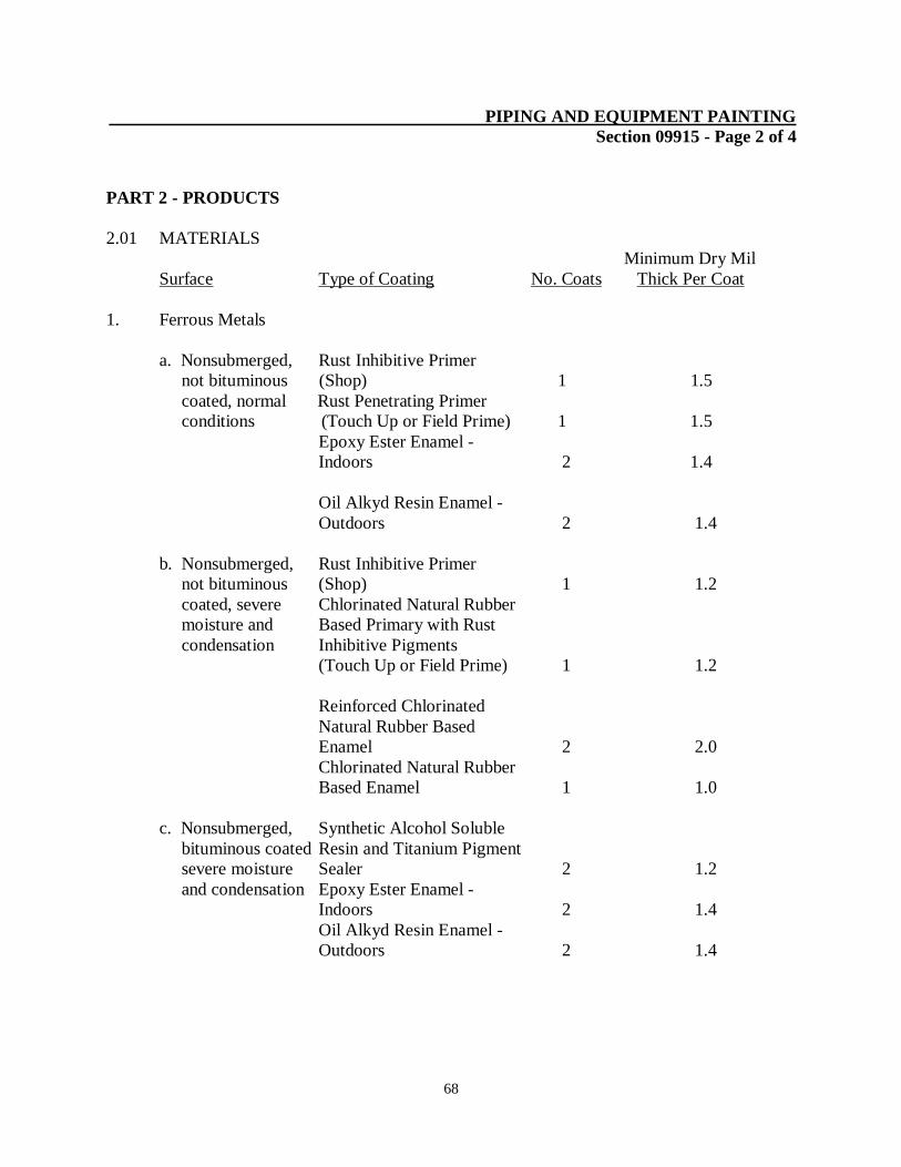
68
PIPING AND EQUIPMENT PAINTING
Section 09915 - Page 2 of 4
PART 2 - PRODUCTS
2.01 MATERIALS
Minimum Dry Mil
Surface Type of Coating No. Coats Thick Per Coat
1. Ferrous Metals
a. Nonsubmerged, Rust Inhibitive Primer
not bituminous (Shop) 1 1.5
coated, normal Rust Penetrating Primer
conditions (Touch Up or Field Prime) 1 1.5
Epoxy Ester Enamel -
Indoors 2 1.4
Oil Alkyd Resin Enamel -
Outdoors 2 1.4
b. Nonsubmerged, Rust Inhibitive Primer
not bituminous (Shop) 1 1.2
coated, severe Chlorinated Natural Rubber
moisture and Based Primary with Rust
condensation Inhibitive Pigments
(Touch Up or Field Prime) 1 1.2
Reinforced Chlorinated
Natural Rubber Based
Enamel 2 2.0
Chlorinated Natural Rubber
Based Enamel 1 1.0
c. Nonsubmerged, Synthetic Alcohol Soluble
bituminous coated Resin and Titanium Pigment
severe moisture Sealer 2 1.2
and condensation Epoxy Ester Enamel -
Indoors 2 1.4
Oil Alkyd Resin Enamel -
Outdoors 2 1.4
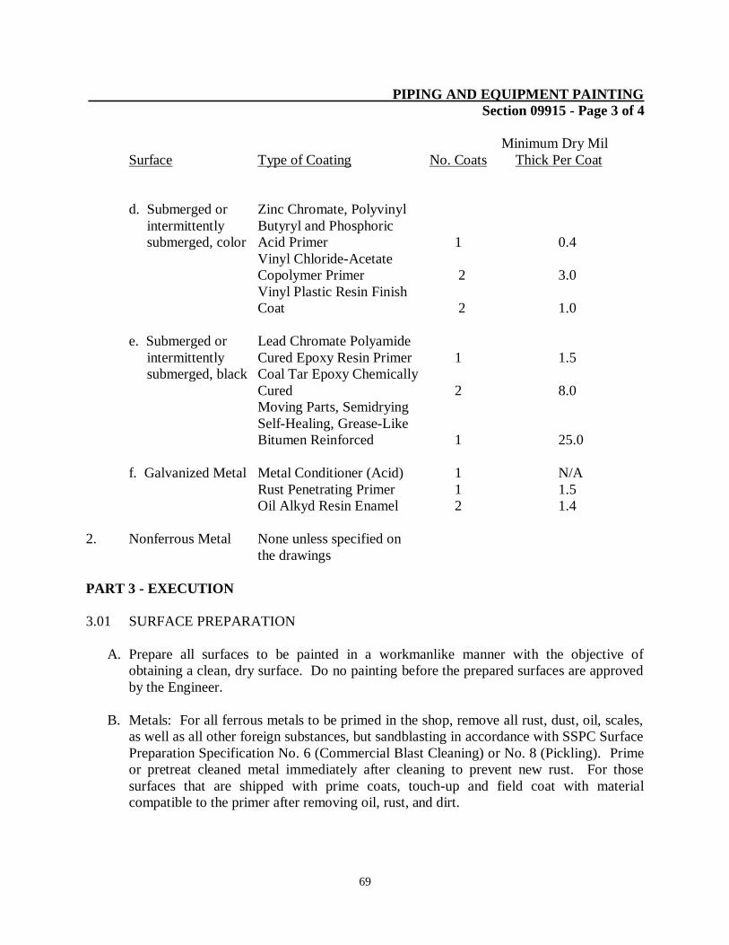
69
PIPING AND EQUIPMENT PAINTING
Section 09915 - Page 3 of 4
Minimum Dry Mil
Surface Type of Coating No. Coats Thick Per Coat
d. Submerged or Zinc Chromate, Polyvinyl
intermittently Butyryl and Phosphoric
submerged, color Acid Primer 1 0.4
Vinyl Chloride-Acetate
Copolymer Primer 2 3.0
Vinyl Plastic Resin Finish
Coat 2 1.0
e. Submerged or Lead Chromate Polyamide
intermittently Cured Epoxy Resin Primer 1 1.5
submerged, black Coal Tar Epoxy Chemically
Cured 2 8.0
Moving Parts, Semidrying
Self-Healing, Grease-Like
Bitumen Reinforced 1 25.0
f. Galvanized Metal Metal Conditioner (Acid) 1 N/A
Rust Penetrating Primer 1 1.5
Oil Alkyd Resin Enamel 2 1.4
2. Nonferrous Metal None unless specified on
the drawings
PART 3 - EXECUTION
3.01 SURFACE PREPARATION
A. Prepare all surfaces to be painted in a workmanlike manner with the objective of
obtaining a clean, dry surface. Do no painting before the prepared surfaces are approved
by the Engineer.
B. Metals: For all ferrous metals to be primed in the shop, remove all rust, dust, oil, scales,
as well as all other foreign substances, but sandblasting in accordance with SSPC Surface
Preparation Specification No. 6 (Commercial Blast Cleaning) or No. 8 (Pickling). Prime
or pretreat cleaned metal immediately after cleaning to prevent new rust. For those
surfaces that are shipped with prime coats, touch-up and field coat with material
compatible to the primer after removing oil, rust, and dirt.
70
PIPING AND EQUIPMENT PAINTING
Section 09915 - Page 4 of 4
C. Sandblast all ferrous metal not primed in the shop in accordance with SSPC Surface
Preparation Specification No. 6 (Commercial Blast Cleaning) in the field prior to
application of the primer, pretreatment, or paint. Solvent clean all nonferrous metals to
be painted, whether they are to be shop or field primed, prior to the application of the
pretreatment and/or primer. In addition, sandblast galvanized surfaces that are to receive
a bitumastic coating as the final finish in order to provide a profile or “tooth”.
3.02 APPLICATION OF PAINT
A. On metal surfaces, the painter shall apply each coat of paint at the rate specified by the
manufacturer to achieve the minimum dry mil thickness required. If material has
thickened or must be diluted for application by spray gun, build up the coating to the
same film thickness achieved with undiluted material. In other words, one gallon of pain
as originally furnished by the manufacturer must not cover a greater square footage when
applied by spray gun than when applied unthinned by brush. Correct deficiencies in film
thickness by applying additional coat(s) of paint. Each coat shall be tested by the
Engineer’s inspector with a microtest mil thickness gauge.
B. Immediately upon completion of the job, submit to the Engineer certification from the
manufacturer indicating that enough coating was purchased to coat all surfaces properly.
Such certification shall make reference to square footage figures provided to the
manufacturer by the Contractor.
C. Drying time shall be construed to mean “under normal conditions”. When conditions are
other than normal because of the weather or because painting must be done in confined
spaces, longer drying times will be necessary. Do not apply additional coats of paint or
return units to service until paints are thoroughly dry.
END OF SECTION