Embed Size (px)
Citation preview
0TECHNICAL SPECIFICATIONS
PRODUCTGROUP

0.0
TECHNICAL SPECIFICATIONS
1. Standard supports ________________________________________________ 0.11.1 Requirements ____________________________________________________ 0.11.2 Definition________________________________________________________ 0.12. LISEGA standard supports _________________________________________ 0.12.1 Scope___________________________________________________________ 0.12.2 Design features __________________________________________________ 0.12.3 Principle of the optimum design type________________________________ 0.23. LISEGA modular system ___________________________________________ 0.23.1 Fundamentals ____________________________________________________ 0.23.2 Scope___________________________________________________________ 0.23.3 Product groups___________________________________________________ 0.23.4 Load groups _____________________________________________________ 0.23.5 Permissible loads_________________________________________________ 0.33.6 Travel ranges ____________________________________________________ 0.63.7 Type designations ________________________________________________ 0.63.8 Type designation system __________________________________________ 0.74. Standards and calculations_________________________________________ 0.95. Materials ________________________________________________________ 0.96. Qualification levels for standard and nuclear application________________ 0.97. Welding________________________________________________________ 0.108. Surface treatment _______________________________________________ 0.108.1 Standard coating systems_________________________________________ 0.108.2 Standard surface protection acc. to products ________________________ 0.118.3 Extended surface protection_______________________________________ 0.118.4 Extended surface protection acc. to products ________________________ 0.128.5 Surface protection in extremely aggressive atmospheres _________________ 0.129. Connection dimensions___________________________________________ 0.129.1 Installation dimension E __________________________________________ 0.129.2 Regulation of the total installation length ___________________________ 0.1310. Operational behavior_____________________________________________ 0.1310.1 Function _______________________________________________________ 0.1310.2 Spring relaxation ________________________________________________ 0.1411. Quality assurance________________________________________________ 0.1411.1 Fundamentals___________________________________________________ 0.1411.2 Quality management _____________________________________________ 0.1411.3 International qualifications ________________________________________ 0.1411.4 Tests and qualifications __________________________________________ 0.1511.5 Suitability tests acc. to KTA 3205.3 and VGB R 510 L_________________ 0.1512. Shipment_______________________________________________________ 0.1613. Warranty _______________________________________________________ 0.1614. Technical modifications___________________________________________ 0.16
CONTENTS PAGE
1
2
3
4
5
6
7
8
9
1
2
3
4
5
6
7
8
9
TECHNICALSPECIFICATIONS
00
0.1
1. STANDARD SUPPORTS
1.1 RequirementsFor the support of industrial piping systems,the use of standard supports is regarded aswell proven, up-to-date technology.
Only a correspondingly high level of standar-dization in support components can adequatelysatisfy the justifiable demand for productsthat are technically top-class and economi-cally attractive at the same time. The complexrequirements for modern pipe supports are:
➜ reliable functioning➜ maintenance-free operation➜ low unit prices➜ simple planning with DP systems➜ instant availability➜ economical installation strategy➜ easy to install designs➜ supplementary service benefits
1.2 DefinitionStandard supports must fulfill the followingcriteria:
➜ component shapes are uniform and designed for optimum exploitation of material
➜ units are compatible regarding connectingdimensions and loading capacity
➜ units are cataloged and clearly identifiableby a designation system
➜ components are manufactured in series production
➜ components comply with the relevant standards and international regulations
➜ functional capacity, suitability and durability of the units is well proven
➜ components are certified and approved for use
The relevant codes for pipe supports inGerman plant construction (power plants),VGB guideline R 510 L, require the preferen-tial use of standard supports and define thecriteria as follows:
“Standard supports are pipe support com-ponents, the construction of which, in formand dimensions as well as in the designdata relating to loading capacity, is certificatedand cataloged, and which are manufacturedaccording to firmly established, reproducibleprocedures, e.g. series production”.
2. LISEGA STANDARD SUPPORTS
2.1 ScopeAt LISEGA, standard supports form the basisof a comprehensive performance package. A complete program from more than 8000standardized components thereby covers alloperational loads, temperatures and travelranges normally met in piping systems inindustrial plant construction:
➜ � 650°C operating temperature for pipe clamps and clamp bases
➜ 400kN nominal load for all mainly statically determined components
➜ 1000kN nominal load for rigid struts and standard shock absorbers
➜ 5000kN design load for large bore shock absorbers
➜ 900mm travel range for constant hangers
➜ 400mm travel range for spring hangers
2.2 Design featuresSpecially developed components are availablefor the various support functions. In thedesign and construction of the units, funda-mental design principles have been takeninto consideration:
➜ symmetrical design shapes➜ compact installation dimensions➜ especially reliable function principles➜ extra wide adjustment ranges➜ fully compatible load ranges and
connection dimensions➜ favorable performance/weight ratios➜ integrated installation aids
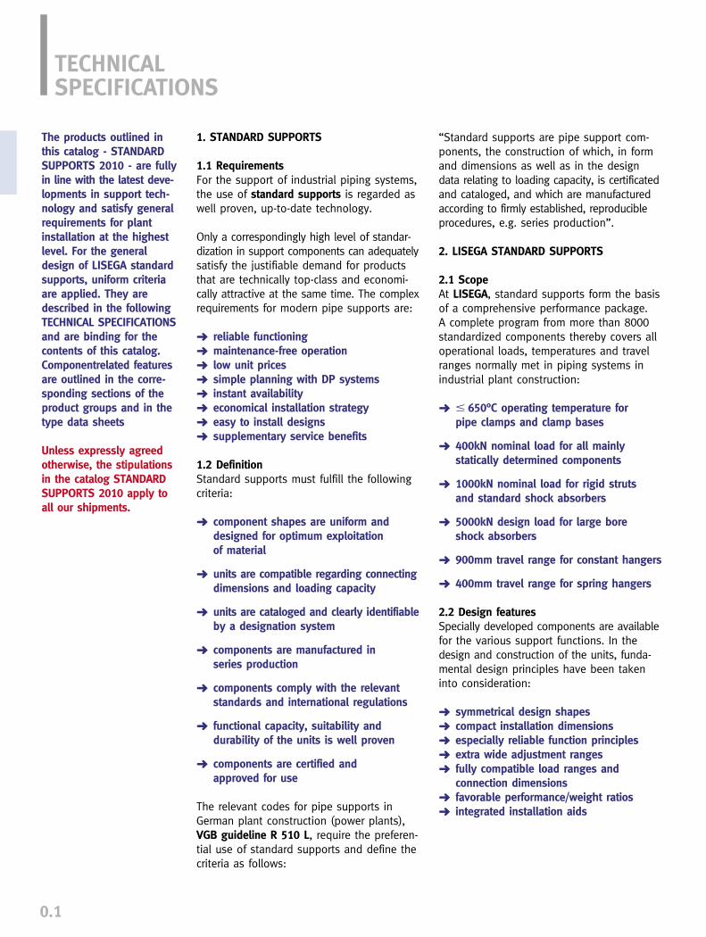
TECHNICAL SPECIFICATIONS
The products outlined inthis catalog - STANDARDSUPPORTS 2010 - are fullyin line with the latest deve-lopments in support tech-nology and satisfy generalrequirements for plantinstallation at the highestlevel. For the generaldesign of LISEGA standardsupports, uniform criteriaare applied. They aredescribed in the followingTECHNICAL SPECIFICATIONSand are binding for thecontents of this catalog.Componentrelated featuresare outlined in the corre-sponding sections of theproduct groups and in thetype data sheets
Unless expressly agreedotherwise, the stipulationsin the catalog STANDARDSUPPORTS 2010 apply toall our shipments.
0.2
0The LISEGA modular system is specially targ-eted towards this efficiency. The standardi-zation of components forms the foundation andis the precondition for rational series produc-tion, dependable quality, systematic warehou-sing and computer assisted application. Withthe LICAD design system and correspondinglogistics, significant rationalization effectscan be achieved in engineering, design andinstallation.
3.2 ScopeThe standardization at LISEGA extends bey-ond the components to their systematic inte-raction. To this end, load and travel distri-bution as well as function and connectionsare meaningfully coordinated.
In this way the LISEGA standard supportprogram has been developed as a functionalmodular system with logical linking. The indi-vidual units form modules therein and arecompatible regarding loads and connections.This enables the formation of meaningful com-binations to produce support configurationsfulfilling all requirements. The large selectionof components makes adaptation possible towidely differing support and applicationsituations.
3.3 Product groupsThe standardized units are divided into 7product groups according to their basic modesof function (see diagram, page 0.3, and table,Standardized Components, page 0.4).
3.4 Load groupsTo guarantee compatible loads in unit com-binations, the load spectrum is split intofixed load groups.Within a load group (nominal load), all com-ponents feature uniform load limits and stresssafety characteristics. The connection shapesof the units (threads - either metric or UNCaccording to market area - or pin diameters)are uniform within a group and thus compat-ible. Components of different product groupscan therefore be connected only within a uni-form load group to safe load chains and thefaulty combination of different load groupsis precluded. As all units in a load group aredesigned uniformly regarding strength, thestresses on a complete chain of components
In addition, LISEGA hangers feature only oneupper attachment point. As a result, and duealso to the compact and symmetrical designshape, the load transfer free of moments tothe connecting elements is ensured and simple installation enabled. The operationalposition of the moving parts (hangers, supports and shock absorbers) can be readdirectly off a travel scale. Load adjustmentof the constant hangers and supports can bemodified at all times, also in the installedcondition under load. Hangers and supportscan be blocked in any travel position.
2.3 Principle of the optimum design typeFor the design of support components, opti-mum coverage of the specific support func-tion is the decisive factor. For each functiononly one component is therefore required,namely, the optimum one for the purpose.The project engineer is spared costly selectionfrom a series of alternative solutions. Thisnot only facilitates application but alsoincreases safety. Above and beyond this, itis a prerequisite for the rational applicationof standardized construction on the principleof the modular system.
➜ There's only ONE best solution!
3. LISEGA MODULAR SYSTEM
3.1 FundamentalsThe cost of pipe supports is a major elementin the total cost of a piping system. The cost of the supports is the accumulatedtotal cost arising from:
➜ project management (processing)➜ design and engineering work➜ use of materials (components) as well as➜ installation work
The pipe supports are almost always criticalfor the commissioning deadline and can,through delayed delivery, cause incalculableextra costs. The aim of LISEGA product stra-tegy is to forge, out of all the cost factors in-volved, the common cost minimum for theuser in the sense of the economic principle.
The economic principle:
= from the least possibleeffort the maximumpossible profit–––––––––––––––––––––––
= Total Cost Minimum/TCM=====================
Product groups
+ load groups+ travel ranges+ connection compatibility
––––––––––––––––––––––= Modular System
===================
Modular System
+ CAD design+ DP logitic systems
––––––––––––––––––––––= High tech application
===================
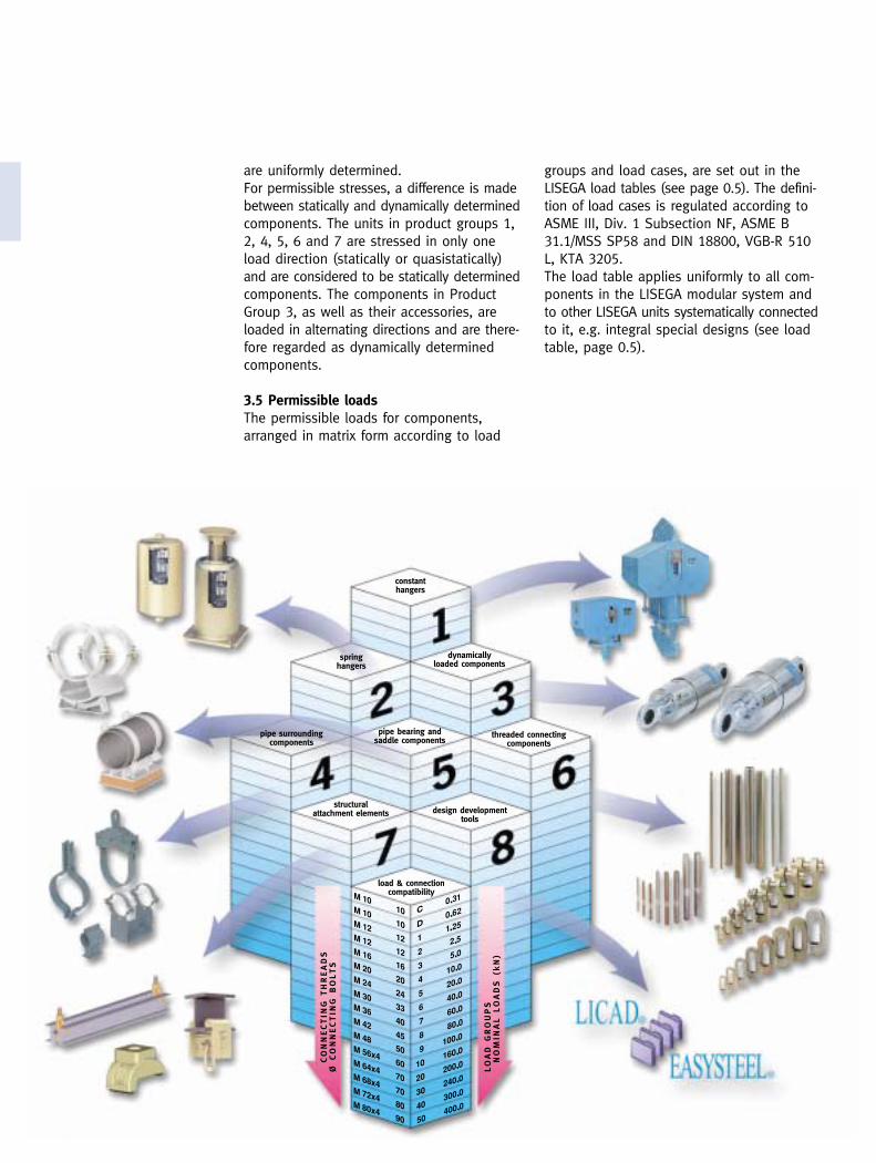
groups and load cases, are set out in theLISEGA load tables (see page 0.5). The defini-tion of load cases is regulated according toASME III, Div. 1 Subsection NF, ASME B31.1/MSS SP58 and DIN 18800, VGB-R 510L, KTA 3205.The load table applies uniformly to all com-ponents in the LISEGA modular system andto other LISEGA units systematically connectedto it, e.g. integral special designs (see loadtable, page 0.5).
0.3
are uniformly determined.For permissible stresses, a difference is madebetween statically and dynamically determinedcomponents. The units in product groups 1,2, 4, 5, 6 and 7 are stressed in only oneload direction (statically or quasistatically)and are considered to be statically determinedcomponents. The components in ProductGroup 3, as well as their accessories, areloaded in alternating directions and are there-fore regarded as dynamically determinedcomponents.
3.5 Permissible loadsThe permissible loads for components,arranged in matrix form according to load
constanthangers
springhangers
pipe surroundingcomponents
pipe bearing and saddle components
threaded connectingcomponents
structuralattachment elements
load & connectioncompatibility
CO
NN
EC
TIN
G T
HR
EA
DS
Ø C
ON
NEC
TIN
G B
OLTS
LO
AD
GR
OU
PS
NO
MIN
AL L
OA
DS
(kN
)
dynamicallyloaded components
design developmenttools
.
.
..............
0.4
0Unittype
Unitdesignation
Group designation
Productgroup
Constant
hangers
Spring
hangers
Dynamically
loaded
components
Pipe
surrounding
components
Pipe
bearings
and saddle
components
Threaded
connecting
elements
Structural
attachment
elements
constant hanger
multi-cell constant hanger
constant support
angulating const. support
servo hanger
support
const. hanger, trapeze
articulated spring support
spring hanger
heavy duty spring hanger
spring hanger, seated
heavy d. spr. hang., seated
sway brace
heavy duty spring support
variable spring support
base plate
spring hanger trapeze
shock absorber
large bore shock absorber
energy absorber
installation extension
weld-on bracket
dynamic pipe clamp
rigid strut
U-bolt
weld-on lug
horizontal clamp
riser clamp
clamp base, lift-off restraints
cylinder roller bearing
double taper roller bearing
double cylinder roller bear.
weld-on pipe saddle
pipe saddle w. pipe clamp
support tray
lift-off restraint
insulated pipe bearing
weld-on pipe shoe
stanchion
elbow pad
eye nut
clevis
turnbuckle
hexagon nut
rod coupling
tie rod L/R
tie rod
threaded rod / stud bolt
weld-on clevis
weld-on pl. w. spher. wash.
weld-on eye nut
beam adapter
connecting plate
beam clamp
trapeze
1
2
3
4
5
6
7
1112-14
1616177179202122252627282972793031323335
36-37394041
42-4445-48
495152535454545556575858606162636465666773747576777879
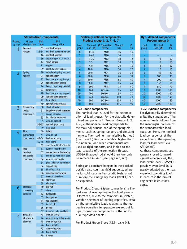
Standardized components
3.5.1 Static componentsThe nominal load is used for the determin-ation of load groups. For the statically deter-mined components in Product Groups 1, 2,4, 6, 7, the nominal load corresponds to the max. adjustment load of the spring ele-ments, such as spring hangers and constanthangers. The maximum permissible hot load(load case H) lies considerably higher thanthe nominal load when components areused as rigid supports, and is tied to theload capacity of the connection threads.LISEGA threaded rod should therefore onlybe replaced in kind (see page 6.5, 6.6).
Spring and constant hangers in the blockedposition also count as rigid supports, where-by for cold loads in hydrostatic tests (shortduration) the emergency loads (level C) canbe exploited.
For Product Group 4 (pipe connections) a lim-ited area of overlapping in the load groupsis foreseen, due to the temperature-related,variable spectrum of loading capacities. Dataon the permissible loads relating to the res-pective operating temperature are set out forpipe connection components in the indivi-dual type data sheets.
For Product Group 5 see 3.5.5, page 0.5.
3.5.2 Dynamic componentsFor dynamically determinedunits, the stipulation of thenominal loads follows fromthe meaningful division ofthe standardizable loadspectrum. Here, the nominalload corresponds at thesame time to the operatingload for load event levelA/B (ASME).As these components aregenerally used to guard against emergencies, theload event level C (ASME),possibly even level D, isusually adopted as the max.expected operating load. In each case the projectengineer’s instructionsapply.
Ø Connectionthread
Ø Pin
Ø Pin
Wrenchsize
Nominalload [kN]
Nominalload [kN]
Loadgroup
Loadgroup
CD123456789
1020304050
M10M10M12M12M16M20M24M30M36M42M48
M56x4M64x4M68x4M72x4M80x4
16161818243036465565758595
100105115
10101212162024334045506070708090
––
101012152030506070
100120140160180
0.310.621.252.55.0
10.020.040.060.080.0100160200240300400
––123456789
1020304050
––
348
1846
100200350550
10002000300040005000
Statically defined componentsProduct group 1, 2, 4, 6, 7
Dyn. defined componentsProduct group 3
0.5
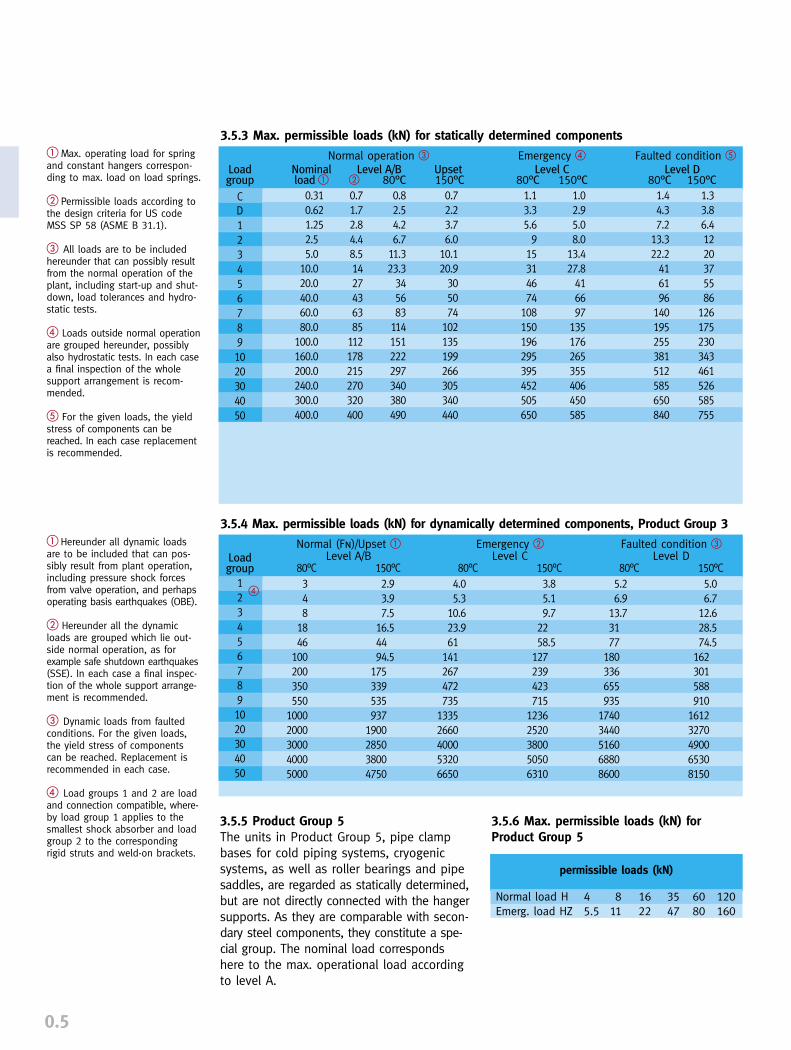
3.5.5 Product Group 5The units in Product Group 5, pipe clampbases for cold piping systems, cryogenicsystems, as well as roller bearings and pipesaddles, are regarded as statically determined,but are not directly connected with the hangersupports. As they are comparable with secon-dary steel components, they constitute a spe-cial group. The nominal load correspondshere to the max. operational load accordingto level A.
� Max. operating load for spring and constant hangers correspon-ding to max. load on load springs.
� Permissible loads according to the design criteria for US code MSS SP 58 (ASME B 31.1).
� All loads are to be included hereunder that can possibly resultfrom the normal operation of theplant, including start-up and shut-down, load tolerances and hydro-static tests.
� Loads outside normal operation are grouped hereunder, possibly also hydrostatic tests. In each case a final inspection of the whole support arrangement is recom-mended.
� For the given loads, the yield stress of components can be reached. In each case replacement is recommended.
� Hereunder all dynamic loadsare to be included that can pos-sibly result from plant operation,including pressure shock forcesfrom valve operation, and perhapsoperating basis earthquakes (OBE).
� Hereunder all the dynamicloads are grouped which lie out-side normal operation, as for example safe shutdown earthquakes(SSE). In each case a final inspec-tion of the whole support arrange-ment is recommended.
� Dynamic loads from faultedconditions. For the given loads,the yield stress of componentscan be reached. Replacement isrecommended in each case.
� Load groups 1 and 2 are loadand connection compatible, where-by load group 1 applies to thesmallest shock absorber and loadgroup 2 to the correspondingrigid struts and weld-on brackets.
Loadgroup
CD1234567891020304050
Normal operation � Emergency � Faulted condition �Nominalload �
0.71.72.84.48.51427436385
112178215270320400
0.82.54.26.7
11.323.3
345683
114151222297340380490
0.72.23.76.0
10.120.9
305074
102135199266305340440
0.310.621.252.55.0
10.020.040.060.080.0
100.0160.0200.0240.0300.0400.0
Level A/B� 80°C
1.13.35.6
915314674
108150196295395452505650
1.02.95.08.0
13.427.8
416697
135176265355406450585
Level C80°C 150°C
1.44.37.2
13.322.2
416196
140195255381512585650840
1.33.86.41220375586
126175230343461526585755
Level D80°C 150°C
Upset150°C
3.5.3 Max. permissible loads (kN) for statically determined components
Loadgroup
1234567891020304050
Normal (Fn)/Upset �Level A/B
80°C 150°C2.93.97.5
16.54494.5
175339535937
1900285038004750
348
1846
100200350550
10002000300040005000
Emergency �Level C
80°C 150°C3.85.19.7
2258.5
127239423715
12362520380050506310
4.05.3
10.623.961
141267472735
13352660400053206650
Faulted condition �Level D
80°C 150°C5.06.7
12.628.574.5
162301588910
16123270490065308150
5.26.9
13.73177
180336655935
17403440516068808600
3.5.4 Max. permissible loads (kN) for dynamically determined components, Product Group 3
permissible loads (kN)
Normal load H 4 8 16 35 60 120Emerg. load HZ 5.5 11 22 47 80 160
3.5.6 Max. permissible loads (kN) forProduct Group 5
�
0.6
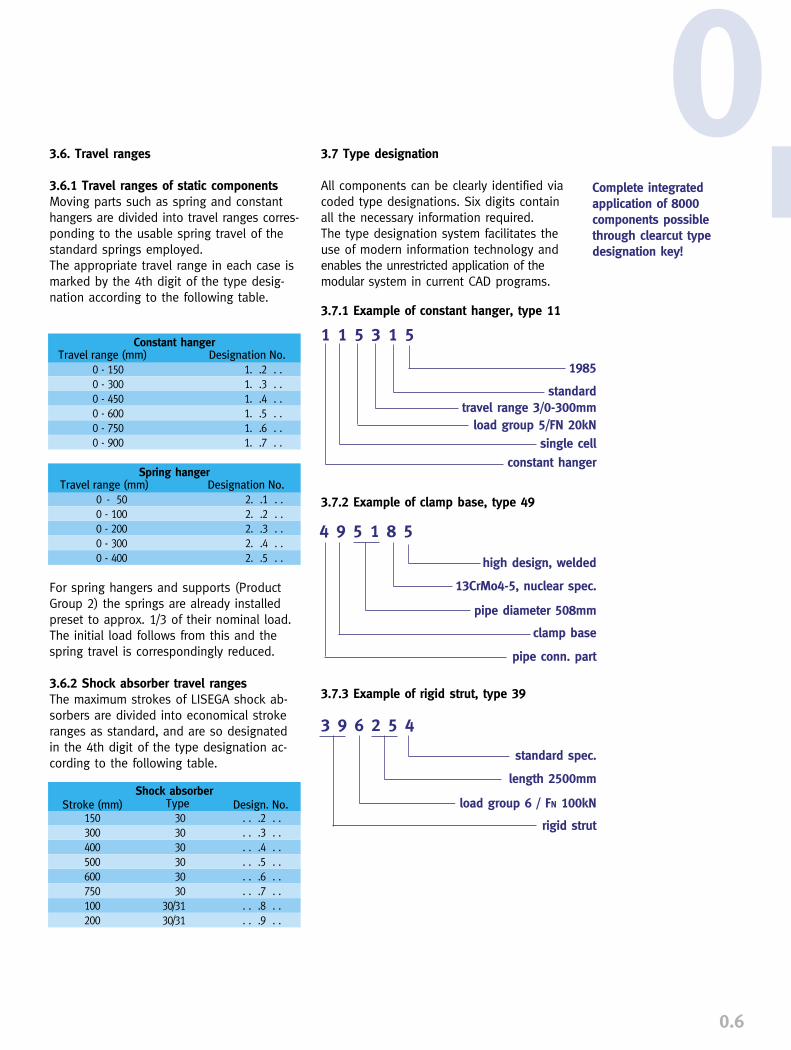
03.6. Travel ranges
3.6.1 Travel ranges of static componentsMoving parts such as spring and constanthangers are divided into travel ranges corres-ponding to the usable spring travel of thestandard springs employed.The appropriate travel range in each case ismarked by the 4th digit of the type desig-nation according to the following table.
For spring hangers and supports (ProductGroup 2) the springs are already installedpreset to approx. 1/3 of their nominal load. The initial load follows from this and thespring travel is correspondingly reduced.
3.6.2 Shock absorber travel rangesThe maximum strokes of LISEGA shock ab-sorbers are divided into economical strokeranges as standard, and are so designatedin the 4th digit of the type designation ac-cording to the following table.
3.7 Type designation
All components can be clearly identified viacoded type designations. Six digits containall the necessary information required. The type designation system facilitates theuse of modern information technology andenables the unrestricted application of themodular system in current CAD programs.
3.7.1 Example of constant hanger, type 11
3.7.2 Example of clamp base, type 49
3.7.3 Example of rigid strut, type 39
1985
standard
single cellconstant hanger
high design, welded
13CrMo4-5, nuclear spec.
clamp base
pipe conn. part
standard spec.
length 2500mm
rigid strut
3 9 6 2 5 4
4 9 5 1 8 5
load group 6 / FN 100kN
load group 5/FN 20kNtravel range 3/0-300mm
pipe diameter 508mm
1 1 5 3 1 5Travel range (mm)
0 - 1500 - 3000 - 4500 - 6000 - 7500 - 900
Constant hangerDesignation No.
1. .2 . .1. .3 . .1. .4 . .1. .5 . .1. .6 . .1. .7 . .
Travel range (mm)
0 - 500 - 1000 - 2000 - 3000 - 400
Spring hangerDesignation No.
2. .1 . .2. .2 . .2. .3 . .2. .4 . .2. .5 . .
Stroke (mm)150300400500600750100200
Type
303030303030
30/3130/31
Shock absorberDesign. No.
. . .2 . .
. . .3 . .
. . .4 . .
. . .5 . .
. . .6 . .
. . .7 . .
. . .8 . .
. . .9 . .
Complete integrated application of 8000 components possiblethrough clearcut type designation key!
0.7
Digit1
Productgroup
1
3.8.1 Constant hangers and constant supportsDigit
2Model
1= constanthanger
6= constantsupport/angulatingconstantsupport
2= CH2-cell coupl.3= CH3-cell coupl.4= CH4-cell coupl.7= servohanger
Digit3
Load group
C=M10-0.31kND=M10-0.62kN1=M12-1.25kN2=M12-2.50kN3=M16-5.00kN4=M20-10.0kN5=M24-20.0kN6=M30-40.0kN7=M36-60.0kN8=M42-80.0kN9=M48-100kN8=M56x4-160kN9=M64x4-200kN8=M68x4-240kN9=M72x4-300kN8=M72x4-320kN9=M80x4-400kN5=M24-20.0kN6=M30-40.0kN7=M36-60.0kN8=M42-80.0kN9=M48-100kN
Digit4
Travelrange
2=150mm3=300mm4=450mm5=600mm6=750mm7=900mm
2=150mm3=300mm
Digit5
Field ofapplication
1=standard5=nuclearapplicationSTANDARD1=std. design2=angulateddesignNUCLEARAPPLICATION5=std. design6=ang. design3=standard7=nuclearapplication
1=standard5=nuclearapplication
Digit6
Prod.series
5=19859=1999
Digit1
Productgroup
2
3.8.2 Spring hangers and spring supportsDigit
2Model
0= angul.spring supp.0= extens. f.type 201= spring h.suspended5= spring h.seated7= sway brace7= extens. f.type 279= spring sup.2= SH, suspended6= SH, seated8= spring sup.
Digit3
Load group
C=M10-0.25kND=M10-0.52kN1=M12-1.25kN2=M12-2.50kN3=M16-5.00kN4=M20-10.0kN5=M24-20.0kN6=M30-40.0kN7=M36-60.0kN8=M42-80.0kN9=M48-100kN
1=M56x4-160kN2=M64x4-200kN3=M68x4-240kN4=M72x4-300kN5=M80x4-400kN
Digit4
Travelrange
1=50mm2=100mm3=200mm4=300mm5=400mm9=extens.f. type 20&. type 27
Digit5
Field ofapplication
1,2=standard5,6=nuclearapplication
Digit6
Prod.series
4=19948=19789=1999
Digit1
Productgroup
4
3.8.4 Pipe clamps and clamp basesDigit
2Model
1= weld-onlug
horiz. clamp2=clevis clamp2=2 bolt clamp3=3 bolt clamp4= with U-bolt or strapriser clamps5=formedriser clamp6=riser cl., lugs8=riser clamp,trunnions9= clampbases
0= U-bolts
9=Lift-offrestraints forclamp bases
Digit3+4
D9 = 0.62kN 29 = 2.5kN39 = 5kN49 = 10kN01 = 21.302 = 26.903 = 33.704 = 42.405 = 48.306 = 60.307 = 73.008 = 76.109 = 88.910 =108.011 =114.313 =133.014 =139.716 =159.017 =168.319 =193.722 =219.1
59 = 20kN69 = 40kN79 = 60kN
24 =244.526 =267.027 =273.032 =323.936 =355.637 =368.041 =406.442 =419.046 =457.251 =508.056 =558.861 =609.666 =660.471 =711.276 =762.081 =812.891 =914.4
Digit5
Field ofapplication
1= standard
1= standard
STANDARD1= up to 350°C2= up to 500°C3= up to 560°C4= up to 600°C5= up to 650°C
NUCLEARAPPLICATION6= up to 350°C7= up to 500°C8= up to 560°C
1= carbonsteel3= stainlesssteel0= Lift-offrestraints
Digit6
Prod.series
f. straight pipes,max. insul. thickn.
1=10mm2=100mm
for pipe elbowsR�1.5OD
max. insul. thickn.3,4=10mm
5,6=100mmdependson load
range anddesign
1=low2=medium3=low, welded4=medium,welded 5=high,welded 8=standard
1-4= size
Pipe diameter in mm
Digit1
Productgroup
3
3.8.3 Dynamic components (cont.)Digit
2Model
5= weld-onbracket
6= dynamicpipe clampwith U-bolt
7=dynamicpipe clampwith strap
9= rigidstruts
Digit3
Load group
Digit4
Travelrange
Digit5
Field ofapplication
1= standard5= nuclearapplication
STANDARD1= up to 350°C2= up to 500°C3= up to 560°CNUCLEARAPPLICATION6= up to 350°C7= up to 500°C8= up to 560°C
middle instal-ation dimens-ion in mm/100
Digit6
Prod.series
1=19913=19936=19869=1989
1-6=U-bolts
1-9=flat steel
strap
3-4=standard
8-9=nuclear
application
19= 3kN 79= 200kN29= 4kN 89= 350kN39= 8kN 99= 550kN49= 18kN 09= 1000kN59= 46kN 20= 2000kN69= 100kN
pipe diameter in mm/10
2 = 4kN 7 = 200kN3 = 8kN 8 = 350kN4 = 18kN 9 = 550kN5 = 46kN 0 =1000kN6 =100kN
Digit1
Productgroup
3
3.8.3 Dynamic componentsDigit
2Model
0= hydraulicshock absor.stand. design2= energyabsorber3= extension
1= hydraulicshock absor.large bore
Digit3
Load group
1= 3kN 4= 18kN 2= 4kN 5= 46kN3= 8kN 6= 100kN7= 200kN8= 350kN9= 550kN0= 1000kN9= 550kN0= 1000kN2= 2000kN3= 3000kN4= 4000kN5= 5000kN
Digit4
Travelrange
2=150mm3=300mm4=400mm5=500mm8=100mm9=200mm
8=100mm9=200mm
Digit5
Field ofapplication
1= standard5= nuclearapplication
Digit6
Prod.series
2=20023=19936=19868=1988
at Type 326=1996
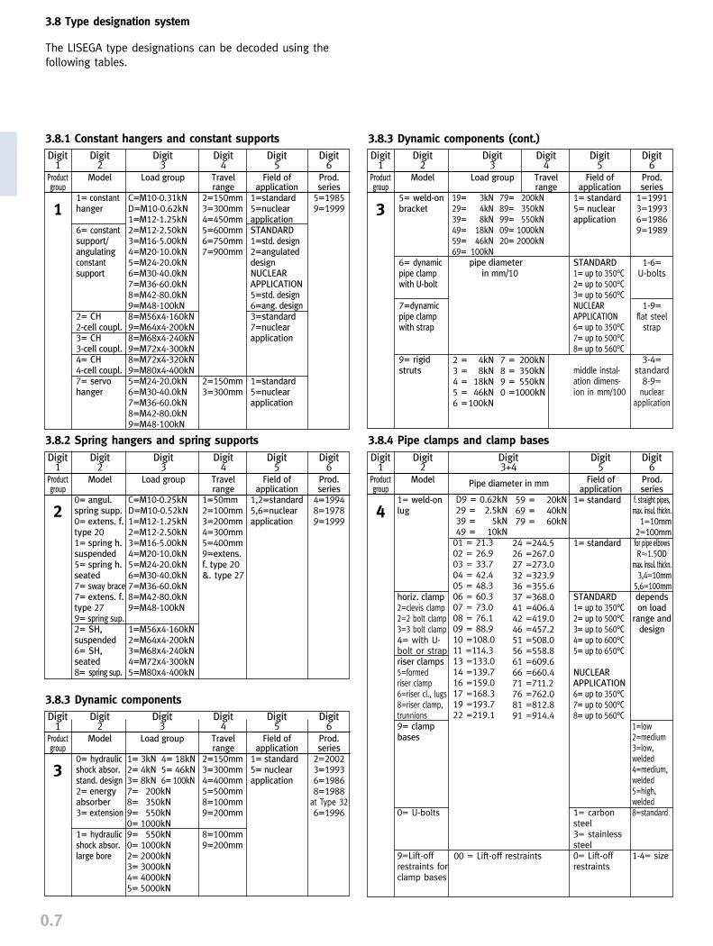
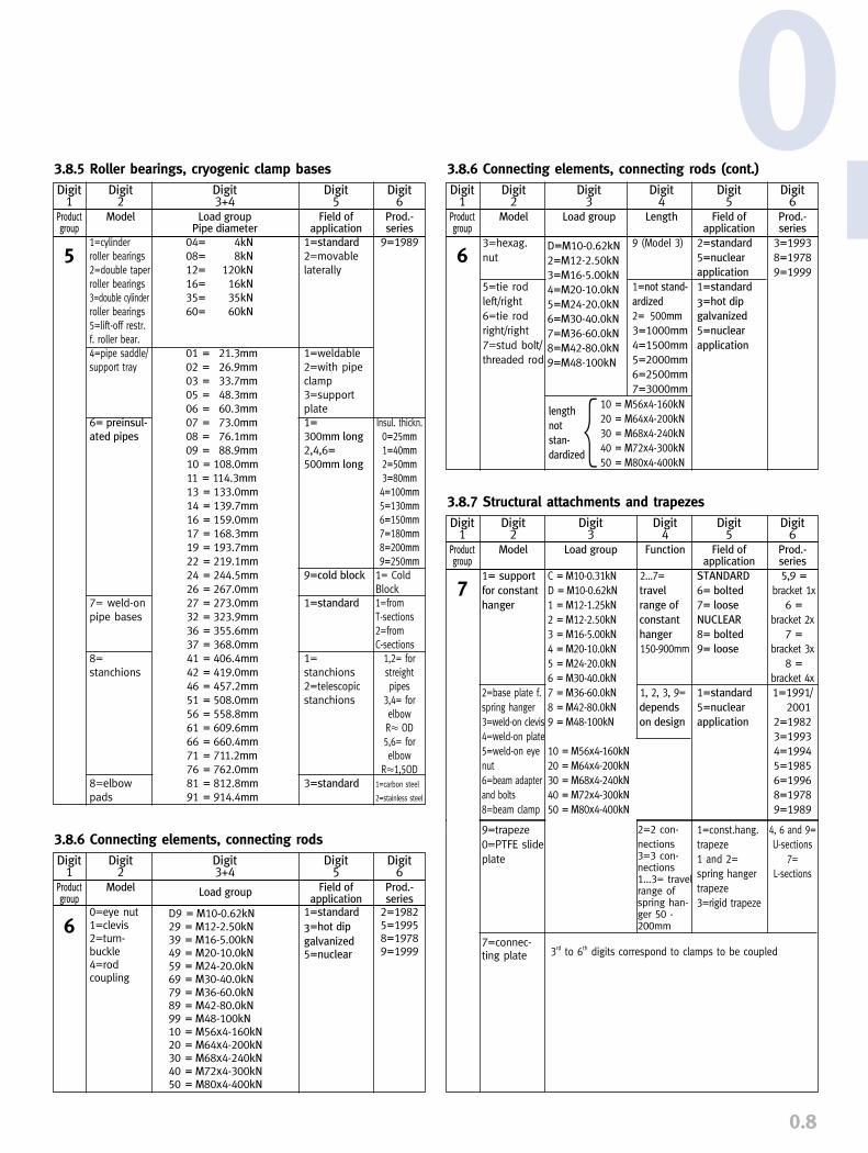
3.8 Type designation system
The LISEGA type designations can be decoded using thefollowing tables.
00 = Lift-off restraints
0.8
Digit1
Productgroup
6
3.8.6 Connecting elements, connecting rods (cont.)Digit
2Model
3=hexag.nut
5=tie rodleft/right6=tie rodright/right7=stud bolt/threaded rod
Digit3
Load group
D=M10-0.62kN
2=M12-2.50kN
3=M16-5.00kN
4=M20-10.0kN
5=M24-20.0kN
6=M30-40.0kN
7=M36-60.0kN
8=M42-80.0kN
9=M48-100kN
Digit4
Length
9 (Model 3)
1=not stand-
ardized
2= 500mm
3=1000mm
4=1500mm
5=2000mm
6=2500mm
7=3000mm
Digit5
Field ofapplication
2=standard
5=nuclear
application
1=standard
3=hot dip
galvanized
5=nuclear
application
Digit6
Prod.-series
3=19938=19789=1999
Digit1
Productgroup
5
3.8.5 Roller bearings, cryogenic clamp basesDigit
2Model
1=cylinder roller bearings2=double taperroller bearings3=double cylinderroller bearings5=lift-off restr.f. roller bear.4=pipe saddle/support tray
6= preinsul-
ated pipes
7= weld-onpipe bases
8=stanchions
8=elbowpads
Digit3+4
Load groupPipe diameter
04= 4kN
08= 8kN
12= 120kN
16= 16kN
35= 35kN
60= 60kN
01 = 21.3mm
02 = 26.9mm
03 = 33.7mm
05 = 48.3mm
06 = 60.3mm
07 = 73.0mm
08 = 76.1mm
09 = 88.9mm
10 = 108.0mm
11 = 114.3mm
13 = 133.0mm
14 = 139.7mm
16 = 159.0mm
17 = 168.3mm
19 = 193.7mm
22 = 219.1mm
24 = 244.5mm
26 = 267.0mm
27 = 273.0mm
32 = 323.9mm
36 = 355.6mm
37 = 368.0mm
41 = 406.4mm
42 = 419.0mm
46 = 457.2mm
51 = 508.0mm
56 = 558.8mm
61 = 609.6mm
66 = 660.4mm
71 = 711.2mm
76 = 762.0mm
81 = 812.8mm
91 = 914.4mm
Digit5
Field ofapplication
1=standard
2=movablelaterally
1=weldable2=with pipeclamp3=supportplate1=
300mm long
2,4,6=
500mm long
9=cold block
1=standard
1=stanchions2=telescopicstanchions
3=standard
Digit6
Prod.-series
9=1989
Insul. thickn.0=25mm
1=40mm
2=50mm
3=80mm
4=100mm
5=130mm
6=150mm
7=180mm
8=200mm
9=250mm
1= ColdBlock1=from T-sections2=from C-sections
1,2= forstreightpipes
3,4= forelbowR� OD5,6= forelbow
R�1,5OD1=carbon steel
2=stainless steel
10 = M56x4-160kN
20 = M64x4-200kN
30 = M68x4-240kN
40 = M72x4-300kN
50 = M80x4-400kN
length
not
stan-
dardized{
Digit1
Productgroup
6
3.8.6 Connecting elements, connecting rodsDigit
2Model
0=eye nut1=clevis2=turn-buckle4=rod coupling
Digit3+4
D9 = M10-0.62kN29 = M12-2.50kN39 = M16-5.00kN49 = M20-10.0kN59 = M24-20.0kN69 = M30-40.0kN79 = M36-60.0kN89 = M42-80.0kN99 = M48-100kN10 = M56x4-160kN20 = M64x4-200kN30 = M68x4-240kN40 = M72x4-300kN50 = M80x4-400kN
Digit5
Field ofapplication
1=standard
3=hot dip
galvanized5=nuclear
Digit6
Prod.-series
2=19825=19958=19789=1999
Load group
9=trapeze0=PTFE slideplate
7=connec-ting plate
2=2 con-nections3=3 con-nections1...3= travelrange ofspring han-ger 50 -200mm
4, 6 and 9=U-sections
7=L-sections
1=const.hang.trapeze1 and 2=spring hangertrapeze3=rigid trapeze
Digit1
Productgroup
7
3.8.7 Structural attachments and trapezesDigit
2Model
1= support
for constant
hanger
2=base plate f.spring hanger3=weld-on clevis4=weld-on plate5=weld-on eyenut6=beam adapterand bolts8=beam clamp
Digit3
Load group
C = M10-0.31kN
D = M10-0.62kN
1 = M12-1.25kN
2 = M12-2.50kN
3 = M16-5.00kN
4 = M20-10.0kN
5 = M24-20.0kN
6 = M30-40.0kN
7 = M36-60.0kN
8 = M42-80.0kN
9 = M48-100kN
10 = M56x4-160kN
20 = M64x4-200kN
30 = M68x4-240kN
40 = M72x4-300kN
50 = M80x4-400kN
Digit4
Function
2...7=travel
range of
constant
hanger
150-900mm
1, 2, 3, 9=depends
on design
Digit6
Prod.-series
5,9 =bracket 1x
6 =
bracket 2x7 =
bracket 3x8 =
bracket 4x1=1991/
20012=19823=19934=19945=19856=19968=19789=1989
Digit5
Field ofapplication
STANDARD
6= bolted
7= loose
NUCLEAR
8= bolted
9= loose
1=standard
5=nuclear
application
0
3rd to 6th digits correspond to clamps to be coupled
MEANS OF CONNECTION
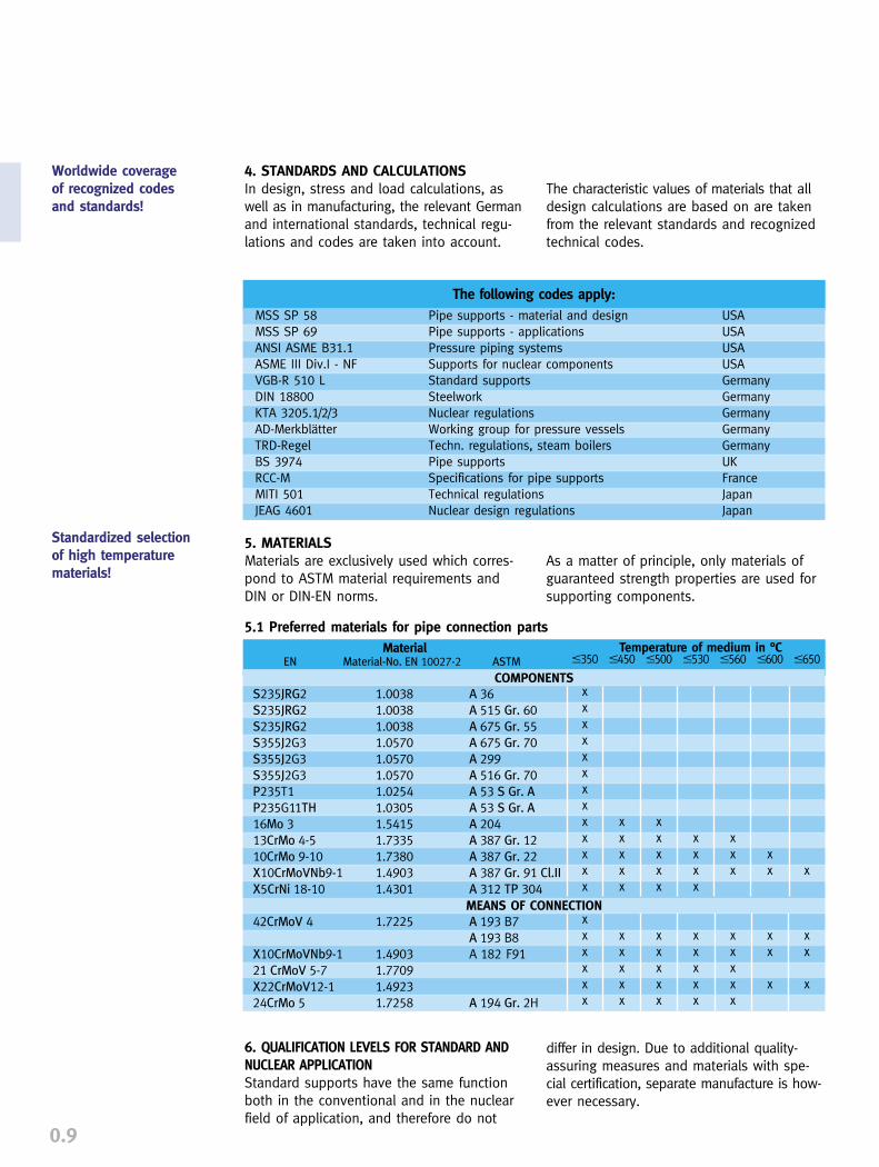
The following codes apply:MSS SP 58 Pipe supports - material and design USAMSS SP 69 Pipe supports - applications USAANSI ASME B31.1 Pressure piping systems USAASME III Div.I - NF Supports for nuclear components USAVGB-R 510 L Standard supports GermanyDIN 18800 Steelwork GermanyKTA 3205.1/2/3 Nuclear regulations GermanyAD-Merkblätter Working group for pressure vessels GermanyTRD-Regel Techn. regulations, steam boilers GermanyBS 3974 Pipe supports UKRCC-M Specifications for pipe supports FranceMITI 501 Technical regulations JapanJEAG 4601 Nuclear design regulations Japan
0.9
5. MATERIALSMaterials are exclusively used which corres-pond to ASTM material requirements andDIN or DIN-EN norms.
As a matter of principle, only materials ofguaranteed strength properties are used forsupporting components.
1.00381.00381.00381.05701.05701.05701.02541.03051.54151.73351.73801.49031.4301
1.7225
1.49031.77091.49231.7258
�350
xxxxxxxxxxxxx
xxxxxx
S235JRG2S235JRG2S235JRG2S355J2G3S355J2G3S355J2G3P235T1P235G11TH
16Mo 313CrMo 4-510CrMo 9-10X10CrMoVNb9-1X5CrNi 18-10
42CrMoV 4
X10CrMoVNb9-121 CrMoV 5-7X22CrMoV12-124CrMo 5
Temperature of medium in °C
A 36A 515 Gr. 60A 675 Gr. 55A 675 Gr. 70A 299A 516 Gr. 70A 53 S Gr. A
A 53 S Gr. A
A 204A 387 Gr. 12A 387 Gr. 22A 387 Gr. 91 Cl.II
A 312 TP 304
A 193 B7A 193 B8A 182 F91
A 194 Gr. 2H
�450
xxxxx
xxxxx
�500
xxxxx
xxxxx
�530
xxxx
xxxxx
�560
xxx
xxxxx
�600
xx
xx
x
�650
x
xx
x
COMPONENTS
6. QUALIFICATION LEVELS FOR STANDARD ANDNUCLEAR APPLICATIONStandard supports have the same functionboth in the conventional and in the nuclearfield of application, and therefore do not
differ in design. Due to additional quality-assuring measures and materials with spe-cial certification, separate manufacture is how-ever necessary.
4. STANDARDS AND CALCULATIONSIn design, stress and load calculations, aswell as in manufacturing, the relevant Germanand international standards, technical regu-lations and codes are taken into account.
MaterialEN Material-No. EN 10027-2 ASTM
The characteristic values of materials that alldesign calculations are based on are takenfrom the relevant standards and recognizedtechnical codes.
5.1 Preferred materials for pipe connection parts
Worldwide coverage of recognized codes and standards!
Standardized selection of high temperature materials!
0.10
0In the field of nuclear application, all mate-rials are traceable right through to the finishedproduct via heat number restamping, and thecomponents themselves are marked accor-ding to ASME and KTA regulations. In thetype designation, the nuclear design is notedin the 5th digit (for struts, the 6th digit). Therelevant component documentation relatesto this and to the fabrication order number.
In this catalog, the standard design, i.e. non-nuclear applications, provides the basis forthe type designations. As the given function-al data and unit dimensions are the same fornuclear applications, selection can also bemade here with the help of the catalog. On planning or ordering, attention must how-ever be paid to corresponding conformity ofthe type designations. The table showing thetype designation system (3.8, page 0.7) can beconsulted in this respect.
7. WELDINGAll welding is carried out as gas metal arcwelding - in special cases by stick welding.LISEGA holds certifications according to:
➜ ASME III Div I NCA NPT stamp➜ DIN EN 729-2 by the German TÜV➜ AD-HPO, production and testing of
pressure vessels, by the TÜV➜ DIN 18800 T7 Extended suitability
certification for steelwork and bridge construction by the SLV, the training and testing institute for welding technology
LISEGA welding inspection personnel are qua-lified according to ASME III NCA 4000 NF,DIN EN 719, AD HP3 and HP4. Non-destructive tests are carried out by testingstaff qualified acc. to ASME IX and DIN EN473, level 2, and SNT-TC-1A, level II.
Supporting connections are produced corres-ponding to the material group by qualifiedwelders according to ASME IX or DIN EN287, part 1. The welding procedure is quali-fied according to ASME IX and DIN EN 288.
8. SURFACE TREATMENT
8.1 Standard coating systemsThe surfaces of LISEGA products are protectedas standard from corrosive influences by highquality protection systems that are also sui-table for external use in aggressive conditions(coastal, industrial and chemical areas). The following coating systems are applied to the different products:
8.1.1 Primer coatingComponents that are either to be welded to existing structure in the plant or simplyrequire higher quality transport protection arecoated on a bright metal surface with wel-dable primer (thickness app. 30µm, color reddish brown).
8.1.2 ElectrogalvanizingSpring hangers and supports up to load size9, as well as all threaded parts and specialfunction parts, are electrogalvanized (zincthickness app. 15µm, yellow chromatized).UNC threaded parts are white chromatized.
8.1.3 Paint coatingsConstant hangers and supports and otherproducts according to table 8.2 receive thefollowing surface treatment:
1. Steel grit blasting according to SP-6 orSP-10 for the U.S. and EN ISO 12944-4grade SA 2 1/2 for Europe.
2. Undercoat of 1-component polyurethanezinc dust primer, dry film thickness 60µm,approx. 62% zinc in solid state volume,color grey.
3. Final coating of 2-component acrylic poly-urethane paint, dry film thickness 60µm,color RAL 5012, light blue.
The total dry film thickness of the systemamounts to approx. 120µm.
8.1.4 Hot dip galvanizationRoller bearings, pipe saddles and cryogenicpipe clamp bases are hot dip galvanized asstandard, zinc thickness approx. 60µm.
Separate manufacture of products for nuclearapplications for the traceability of qualified materials!
0.11
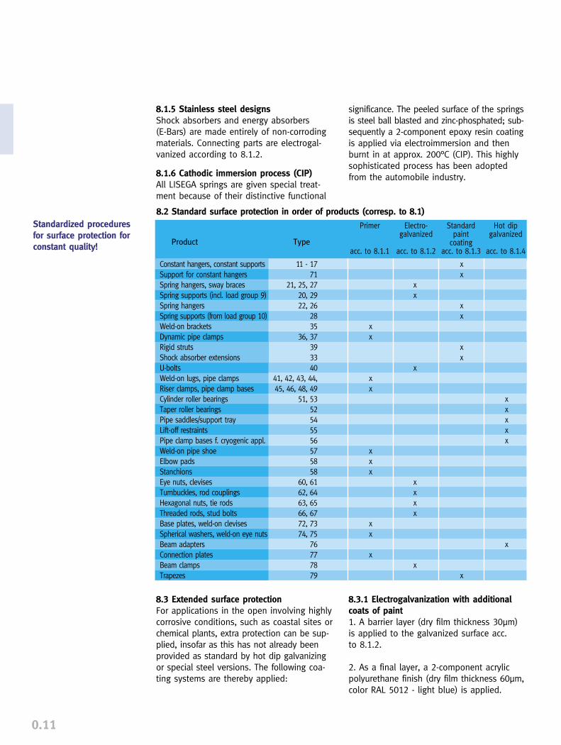
Product Type
Standardpaint
coatingacc. to 8.1.3
Electro-galvanized
acc. to 8.1.2
Primer
acc. to 8.1.1
Hot dipgalvanized
acc. to 8.1.4
11 - 1771
21, 25, 2720, 2922, 26
2835
36, 37393340
41, 42, 43, 44, 45, 46, 48, 49
51, 5352545556575858
60, 6162, 6463, 6566, 6772, 73 74, 75
76777879
Constant hangers, constant supportsSupport for constant hangersSpring hangers, sway bracesSpring supports (incl. load group 9)Spring hangersSpring supports (from load group 10)Weld-on bracketsDynamic pipe clampsRigid strutsShock absorber extensionsU-boltsWeld-on lugs, pipe clampsRiser clamps, pipe clamp basesCylinder roller bearingsTaper roller bearingsPipe saddles/support trayLift-off restraintsPipe clamp bases f. cryogenic appl.Weld-on pipe shoeElbow padsStanchionsEye nuts, clevisesTurnbuckles, rod couplingsHexagonal nuts, tie rodsThreaded rods, stud boltsBase plates, weld-on clevisesSpherical washers, weld-on eye nutsBeam adaptersConnection platesBeam clampsTrapezes
xx
xx
xx
x
xx
x
xxxx
x
xx
xx
xxx
xx
x
xxxxx
x
8.2 Standard surface protection in order of products (corresp. to 8.1)
8.3 Extended surface protectionFor applications in the open involving highlycorrosive conditions, such as coastal sites orchemical plants, extra protection can be sup-plied, insofar as this has not already beenprovided as standard by hot dip galvanizingor special steel versions. The following coa-ting systems are thereby applied:
8.3.1 Electrogalvanization with additionalcoats of paint1. A barrier layer (dry film thickness 30µm)is applied to the galvanized surface acc. to 8.1.2.
2. As a final layer, a 2-component acrylicpolyurethane finish (dry film thickness 60µm,color RAL 5012 - light blue) is applied.
8.1.5 Stainless steel designsShock absorbers and energy absorbers (E-Bars) are made entirely of non-corrodingmaterials. Connecting parts are electrogal-vanized according to 8.1.2.
8.1.6 Cathodic immersion process (CIP)All LISEGA springs are given special treat-ment because of their distinctive functional
significance. The peeled surface of the springsis steel ball blasted and zinc-phosphated; sub-sequently a 2-component epoxy resin coatingis applied via electroimmersion and thenburnt in at approx. 200°C (CIP). This highlysophisticated process has been adoptedfrom the automobile industry.
Standardized proceduresfor surface protection forconstant quality!
0.12
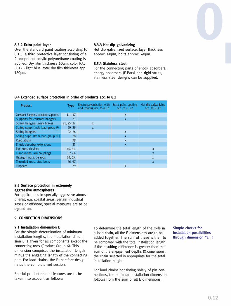
Product Type Extra paint coatingacc. to 8.3.2
Hot dip galvanizingacc. to 8.3.3
11 - 1771
21, 25, 2720, 2922, 26
283933
60, 61, 62, 6463, 65, 66, 67
79
Constant hangers, constant supportsSupports for constant hangersSpring hangers, sway bracesSpring supp. (incl. load group 9)Spring hangersSpring supp. (from load group 10)Rigid strutsShock absorber extensionsEye nuts, clevisesTurnbuckles, rod couplingsHexagon nuts, tie rodsThreaded rods, stud boltsTrapezes
xx
xxxx
x
Electrogalvanization withadd. coating acc. to 8.3.1
xx
xxxx
8.4 Extended surface protection in order of products acc. to 8.3
8.5 Surface protection in extremely aggressive atmospheresFor applications in specially aggressive atmos-pheres, e.g. coastal areas, certain industrialgases or offshore, special measures are to beagreed on.
9. CONNECTION DIMENSIONS
9.1 Installation dimension EFor the simple determination of minimuminstallation lengths, the installation dimen-sion E is given for all components except theconnecting rods (Product Group 6). Thisdimension comprises the installation lengthminus the engaging length of the connectingpart. For load chains, the E therefore desig-nates the complete rod section.
Special product-related features are to betaken into account as follows:
0
To determine the total length of the rods ina load chain, all the E dimensions are to beadded together. The sum of these is then tobe compared with the total installation length.If the resulting difference is greater than thesum of the engagement depths (X dimensions),the chain selected is appropriate for the totalinstallation height.
For load chains consisting solely of pin con-nections, the minimum installation dimensionfollows from the sum of all E dimensions.
8.3.2 Extra paint layerOver the standard paint coating according to8.1.3, a third protective layer consisting of a2-component acrylic polyurethane coating isapplied. Dry film thickness 60µm, color RAL5012 - light blue, total dry film thickness app.180µm.
8.3.3 Hot dip galvanizingHot dip galvanized surface, layer thicknessapprox. 60µm, bolts approx. 40µm.
8.3.4 Stainless steelFor the connecting parts of shock absorbers,energy absorbers (E-Bars) and rigid struts,stainless steel designs can be supplied.
Simple checks for installation possibilitiesthrough dimension “E” !

0.13
Sensible devices on handfor readjusting installationlengths!
9.2 Regulation of the total installationlength
9.2.1 Turnbuckle function of the connectingthreadsFor length adjustment in installation condition(adjustment of pipe installation position, ac-tuation of loading), the lower connections inconstant and spring hangers provide a turn-buckle function. This way, subsequent adjust-ment of the installation lengths (attachmentrods) within a sufficient range is possible:
➜ for constant hangers type 11, by 300mm
➜ for spring hangers type 21, by the adjustment possibility of a turnbuckle, type 62
➜ for spring hangers type 22, by min. 140mm
➜ for spring hangers types 25 and 26, the load bearing rod is fed through the weld-on support tube and fixed with an adjustment nut. The adjustment can be made within the scope of the avai-lable threaded length of the rod.
All connection threads are supplied as righthand threads.
9.2.2 Spring supportsFor spring supports types 28 and 29, theinstallation height can be regulated by thesupport tube, functioning as a spindle inde-pendently of the presetting. The necessary load is actuated on installationby screwing the support tube upwards.
9.2.3 Turnbuckle, type 62, tie rod, lefthand/right hand thread, type 65For rigid hanging support arrangements withshort installation lengths, a defined reservelength in the connection parts type 60 and61 usually enables sufficient length adjust-ment. For longer installation lengths, the useof a turnbuckle L/R, type 62, in conjunctionwith a tie rod L/R, type 65, is appropriate.For easy access, this combination should bearranged at the lower end of the load chain.
9.2.4 Rigid struts, type 39The connections in rigid struts type 39 aresupplied as left/right, with fine threading forlength adjustment in the installation conditionas standard.Flat faces on the body of the rigid struts en-able simple adjustment with a wrench.
10. OPERATIONAL BEHAVIOR
10.1 FunctionConstant hangers type 1 are designed so thatin theory no load deviation occurs over thewhole range of action. The total deviationresulting from springs, bearing friction, andfabrication tolerances is held to within � 5%in series production. The load adjustment follows with a level ofaccuracy of 2%.
For spring hangers and supports, the loadalters linearly corresponding to the springtravel. The deviation of the spring force fromtheoretical values, resulting from spring hys-teresis and fabrication tolerances, amounts toless than � 5% within the ordered travel.
FN = nominal loadF min = min. load (upwards)F max = max. load (downwards)SN = nominal travel (incl. reserve)
FN = nominal loadSN = nominal travel (incl. reserve)S = operating travel
load
Flo
ad F
travel s
travel s
operating load
0.14
0measures are prescribed. They are an integralpart of order processing and embrace thewhole LISEGA group.
11.2 Quality management program, QMPThe QMP is clearly laid out in a quality ma-nagement manual, QMM, and regulates all thequality-assuring activities in the company.The QMM covers the organization as a whole,whereby the observance of rules is monitoredby the independent quality management de-partment QM. The QMM has been compiledaccording to international quality norms andstandards and specifically takes into accountthe regulations according to ASME III - NCA3800 and NCA 4000 incl. NF as well as DINEN ISO 9001 and KTA 1401.
The QMM applies in principle to both the con-ventional and nuclear fields. The extent ofmonitoring of materials and tests, as well asthe documentation, can in each case be exactly adapted to special requirements by theuse of extended QA levels. All internationalrequirements concerning nuclear applicationscan be covered. Corresponding qualificationsare available and are regularly renewed.
Certifying body
Lloyd’s Register QAL’AFAQASME Accreditation andCertificationASME Accreditation andCertificationTÜV Nord e.V.(independent Germanauthority)SLV-Hannover
TRACTEBEL (Vincotte)DET NORSKE VERITASNUPIC
Certification No.
Reg.Nr. 2005501996/5030N-2951
QSC 552
0121WO2978407-702-019407-703-008060317/62/9804
No. 1606No. DNV 5477CEXO-99/00210
Certification code
DIN/EN/ISO 9001DIN/EN/ISO 9001ASME-III NCA 4000/NF(NPT-Stamp)ASME-III NCA 3800/NF
Stamping agreementAD-Merkblatt HP 0; HP 3; HP 4Welding certification according to EN 729-2DIN 18800T7 Major qualification certificateASME III - NCA/NF; ASME IXSKIFS 1994:1ASME-III NF/NCA 3800;10CFR50 App. B; 10CFR21;N45.2; NQA1
11.3 International qualifications
QMP and Processing constitute a single entity!
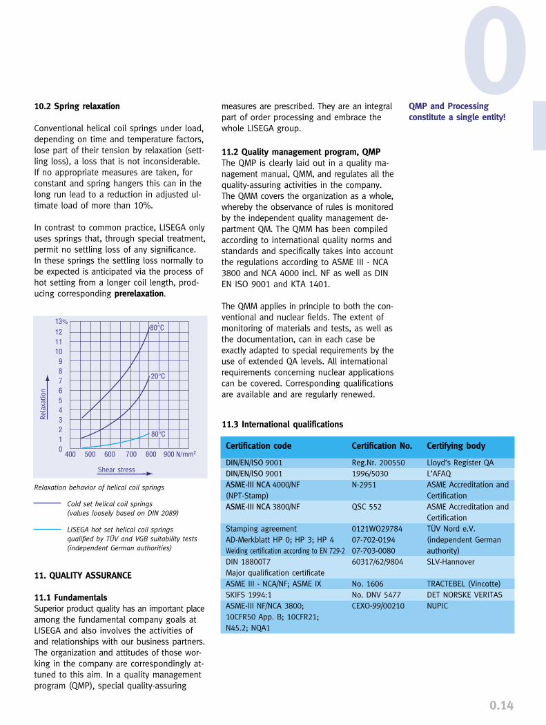
10.2 Spring relaxation
Conventional helical coil springs under load,depending on time and temperature factors,lose part of their tension by relaxation (sett-ling loss), a loss that is not inconsiderable.If no appropriate measures are taken, forconstant and spring hangers this can in thelong run lead to a reduction in adjusted ul-timate load of more than 10%.
In contrast to common practice, LISEGA onlyuses springs that, through special treatment,permit no settling loss of any significance. In these springs the settling loss normally tobe expected is anticipated via the process ofhot setting from a longer coil length, prod-ucing corresponding prerelaxation.
11. QUALITY ASSURANCE
11.1 FundamentalsSuperior product quality has an important placeamong the fundamental company goals atLISEGA and also involves the activities ofand relationships with our business partners.The organization and attitudes of those wor-king in the company are correspondingly at-tuned to this aim. In a quality managementprogram (QMP), special quality-assuring
Relaxation behavior of helical coil springs
Cold set helical coil springs(values loosely based on DIN 2089)
LISEGA hot set helical coil springs qualified by TÜV and VGB suitability tests(independent German authorities)
Rela
xatio
n
Shear stress
11.4 Tests and qualifications
11.4.1 Raw material and material receptionAll materials used undergo receiving controlby the quality management department. Thematerials used are qualified, correspondingto requirements by material tests accordingto ASME and DIN EN 10204.
11.4.2 Monitoring of manufactureManufacture is monitored via accompanyingquality control according to the QM manual.
In particular, for nuclear applications thequality-assuring requirements according toASME III NF and KTA are fulfilled.
11.4.3 Final inspectionBefore shipment, constant and spring hangersas well as shock absorbers undergo a func-tion test on test benches by quality manage-ment personnel. The tests are carried outusing computer-assisted equipment. Thevalues measured can be recorded by meansof a diagram. In addition, for constant andspring hangers the digital values can beprinted out over the whole travel range.
The specific test benches employed undergoregular inspections by an independent super-visory body.
11.4.4 Documentation on shipmentIf so ordered, the materials used are docum-ented by certification from material tests ac-cording to ASME and DIN EN 10204. In addi-tion, the results of the function tests can beconfirmed by issuing an acceptance test certificate, also from a supervisory body ifdesired.
0.15
Stress reports according to particular specif-ications and quality-assuring documents canbe agreed between customer, manufacturerand supervisory body.
11.5 Suitability test according to KTA 3205.3and type test according to VGB R 510 L
For the use of series-made standard supportsin conventional power plants, a type test by asupervisory body (according to § 14 of theappliance safety law GSG) is foreseen in theVGB code R 510 L.
For use in nuclear installations a correspon-ding suitability test, according to directive 35of the TÜV’s nuclear technology supervisorybody at the Vd TÜV, is prescribed by nuclearcode KTA 3205.3.
The test program prescribed comprises inessence the following components:
➜ inspection of the quality management program
➜ inspection of material used
➜ inspection of the design documentation
➜ inspection of design report summaries
➜ experimental function tests
➜ experimental overload tests
➜ experimental testing of continuous load capacity
For the broad range of LISEGA products, typeand suitability tests have been conductedby the German TÜV and VGB and the corres-ponding permits granted. Qualifications canbe supplied on request
Proven operational safetyand long life through typeand suitability tests!
0.16
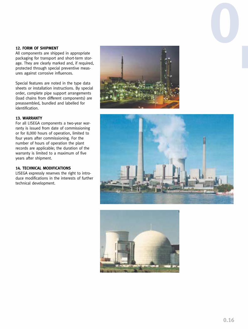
12. FORM OF SHIPMENTAll components are shipped in appropriatepackaging for transport and short-term stor-age. They are clearly marked and, if required,protected through special preventive meas-ures against corrosive influences.
Special features are noted in the type datasheets or installation instructions. By specialorder, complete pipe support arrangements(load chains from different components) arepreassembled, bundled and labelled foridentification.
13. WARRANTYFor all LISEGA components a two-year war-ranty is issued from date of commissioningor for 8,000 hours of operation, limited tofour years after commissioning. For thenumber of hours of operation the plantrecords are applicable; the duration of thewarranty is limited to a maximum of fiveyears after shipment.
14. TECHNICAL MODIFICATIONSLISEGA expressly reserves the right to intro-duce modifications in the interests of furthertechnical development.
0