Embed Size (px)
Citation preview
TECHNICAL SPECIFICATION
SECTION-A
CMM/MAPS/MM/41537/MANUAL-PO/1291 DT:-
Welding Specification:
1. The tank should be fabricated from steel plate material confirming to IS 2062
Gr-B.
2. Material test certificates, verification&identification mark and visual inspection
of the plate should be made before start of pre-fabrication.
3. Cold bending of steel plate should be done such that no dent marks damage
on the plate.
Welding procedure:
All welding should be done as per approved welding procedure attached
herewith.
Welders Qualification:
All welding joints should be done by the qualified welders as per ASME
Sec.IX.Relevant performance qualification certificate should be produced for
verification before start of the work at any time during the fabrication of the
tank.
Welding inspection:
The type and extent of weld examination as given (Visual,DPT,Radiography)in
Annexure-B should be strictly followed. Inspection should be done by qualified
inspector of the contractor and same to be offered to NPCIL/QAI inspector and
clearance should be obtained at various stages. No welding defects such as lack
of fusion/lack of penetration/insufficient fillet size and any other defects is not
permitted. All nozzle joints and butt joints root side to be ground and one more
welding pass is required at the root side.
All MTC, welding inspection documents should be submitted along with the
supply.
A proposed QA Plan is attached herewith. However the contractor may submit
their own QA plan and the same to be approved by SME (M) before the
commencement of work.
Hydrostatic test:
Before rubber lining and external coating the tank has to be
leak tested by conducting hydrostatic test/water fill test as per the approved
procedure by NPCIL/QAI.
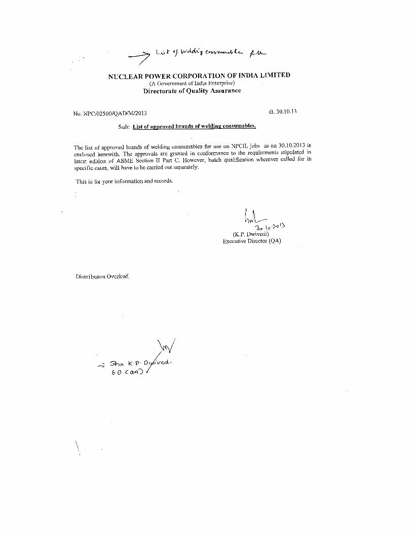
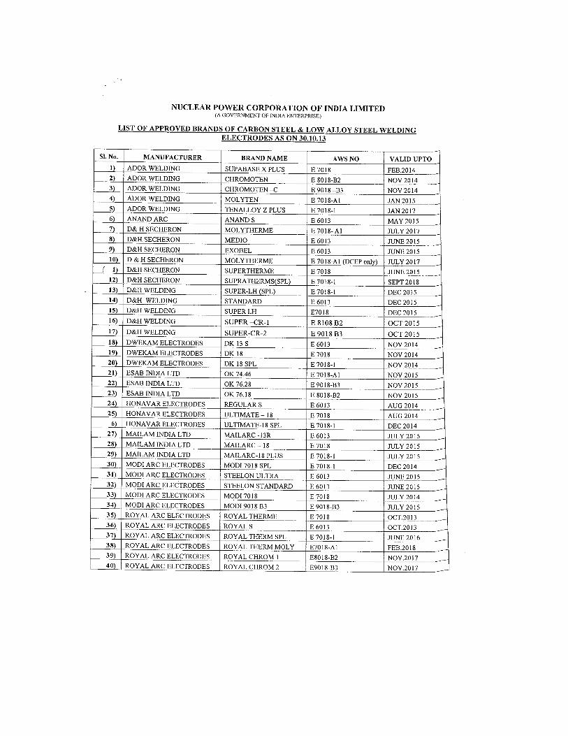
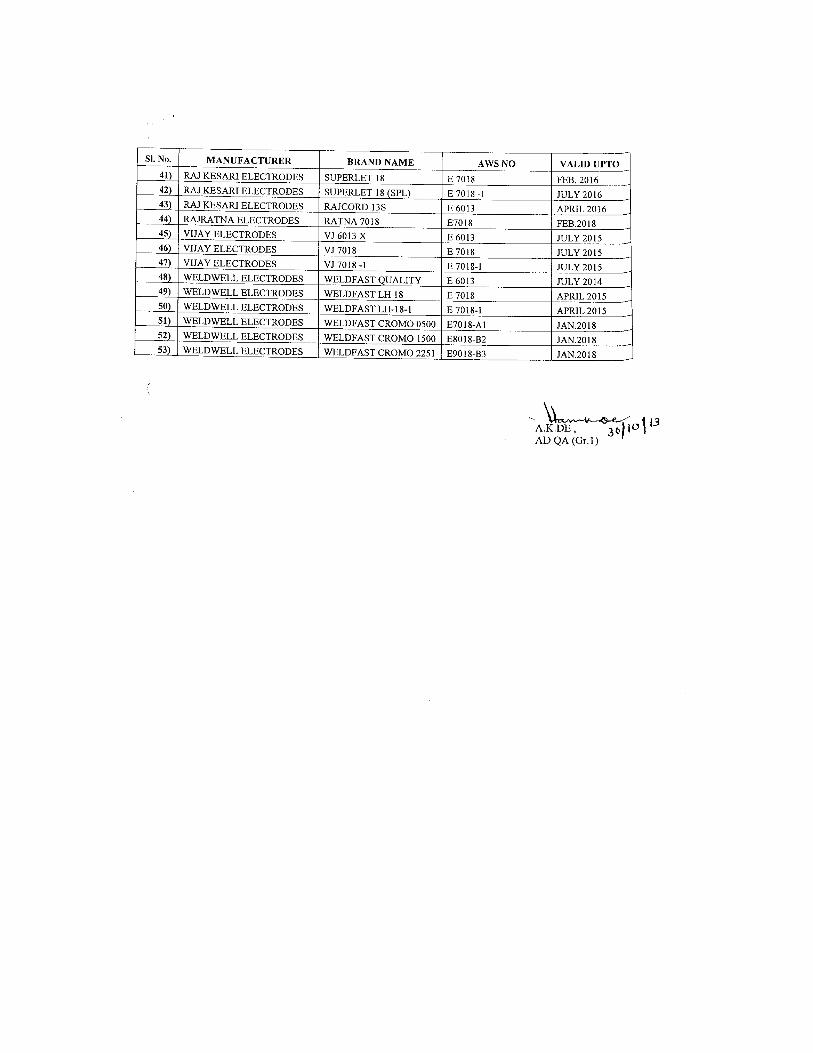
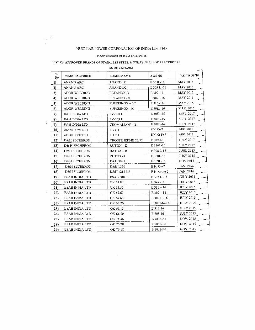
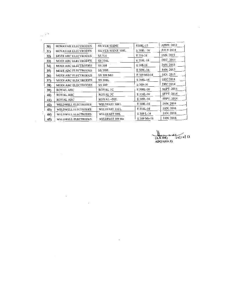
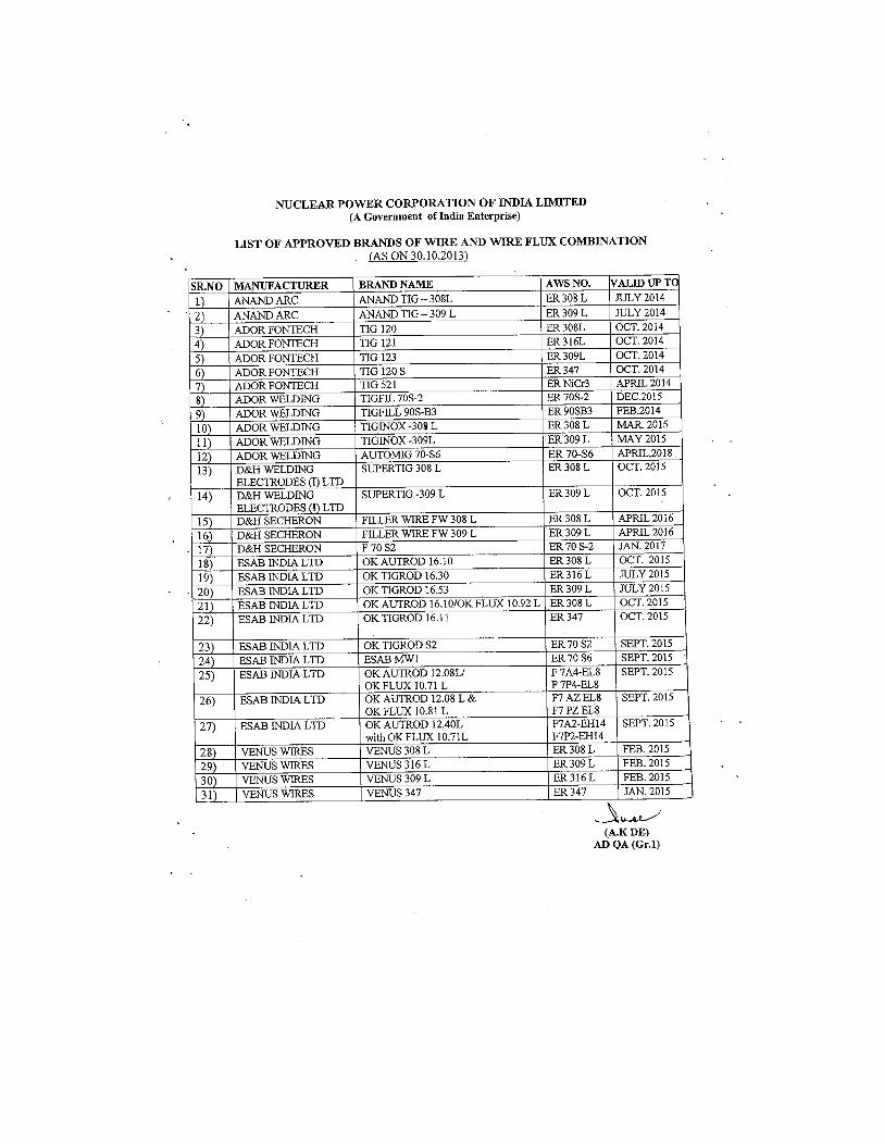
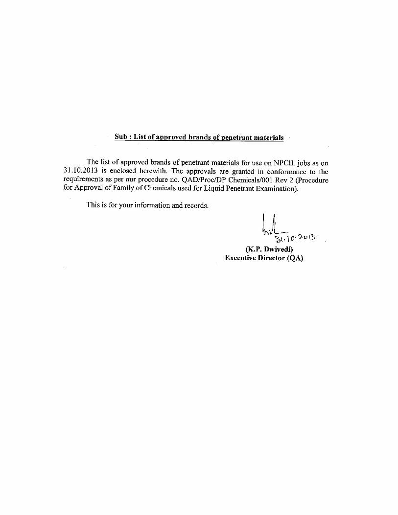
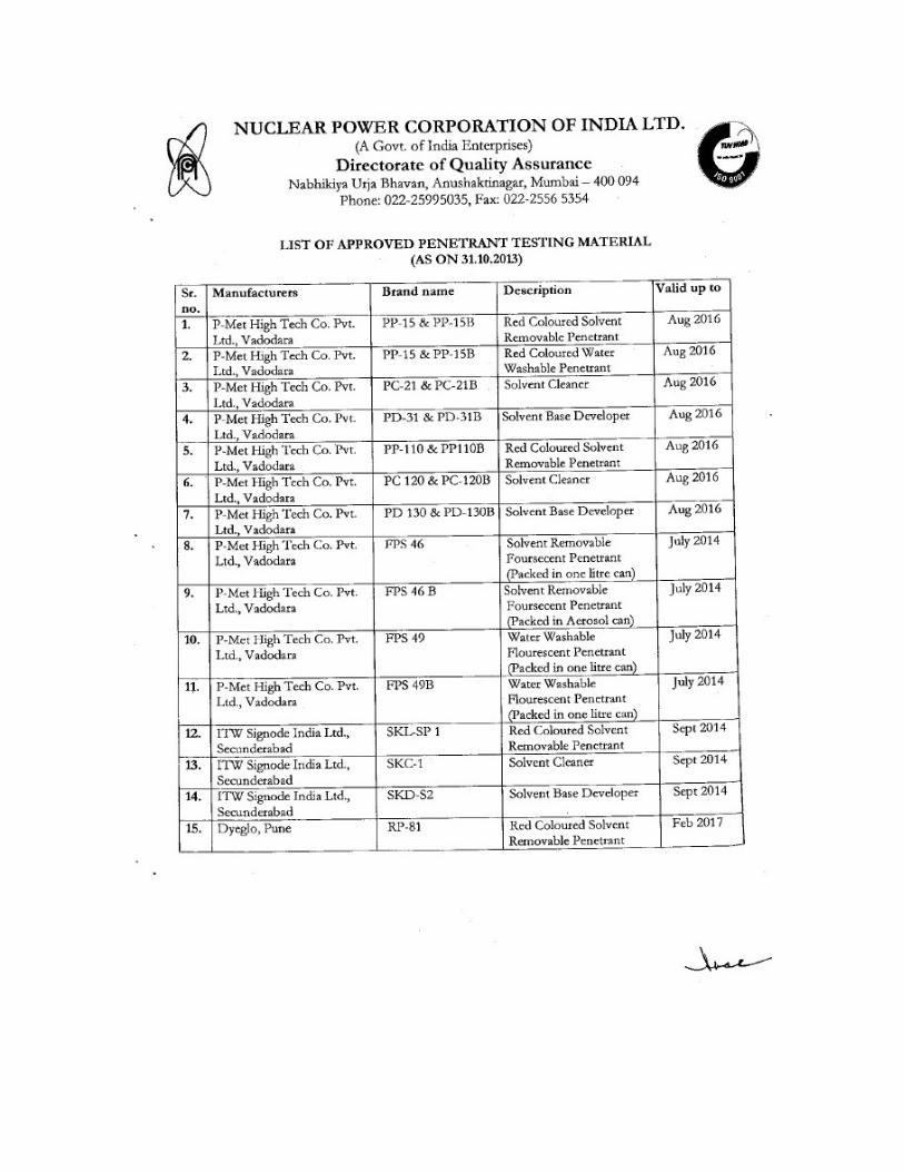
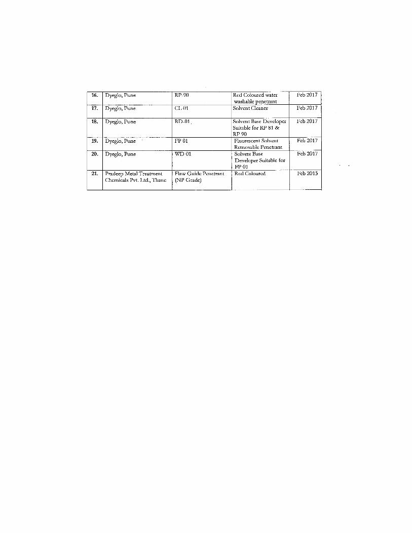
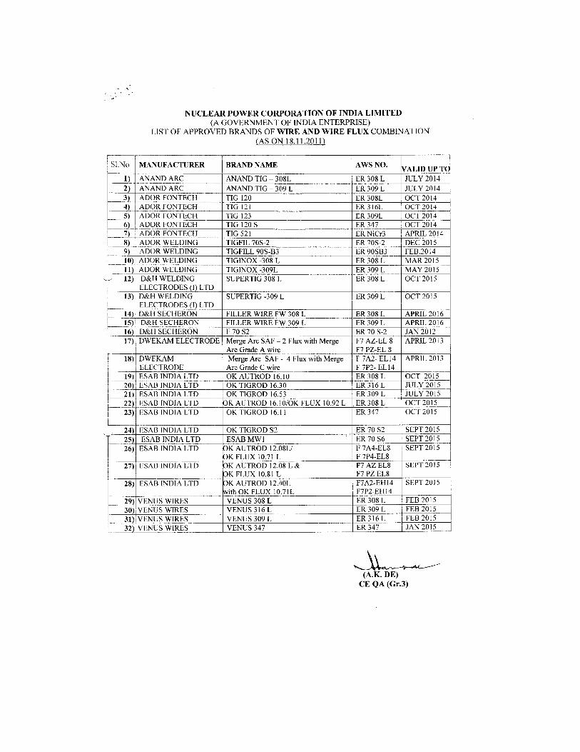
Welding consumables:
Only NPCIL/QA approved brands of consumables like
welding electrodes and penetrant materials to be used for entire welding works
as listed below:
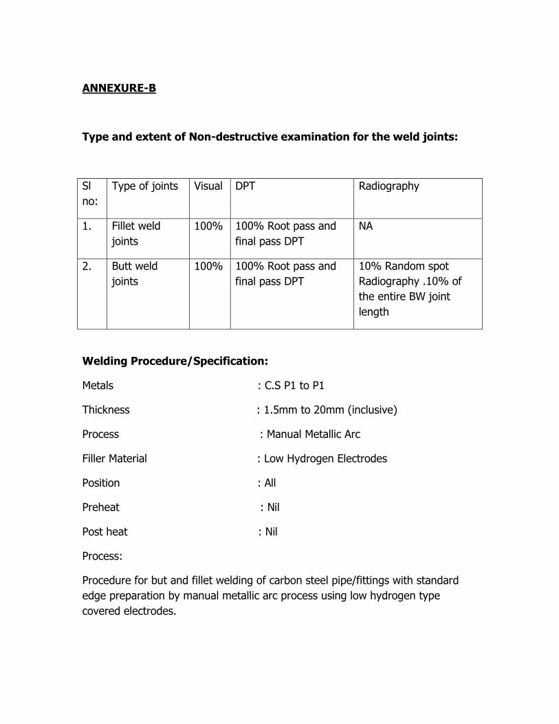
ANNEXURE-B
Type and extent of Non-destructive examination for the weld joints:
Sl
no:
Type of joints Visual DPT Radiography
1. Fillet weld
joints
100% 100% Root pass and
final pass DPT
NA
2. Butt weld
joints
100% 100% Root pass and
final pass DPT
10% Random spot
Radiography .10% of
the entire BW joint
length
Welding Procedure/Specification:
Metals : C.S P1 to P1
Thickness : 1.5mm to 20mm (inclusive)
Process : Manual Metallic Arc
Filler Material : Low Hydrogen Electrodes
Position : All
Preheat : Nil
Post heat : Nil
Process:
Procedure for but and fillet welding of carbon steel pipe/fittings with standard
edge preparation by manual metallic arc process using low hydrogen type
covered electrodes.
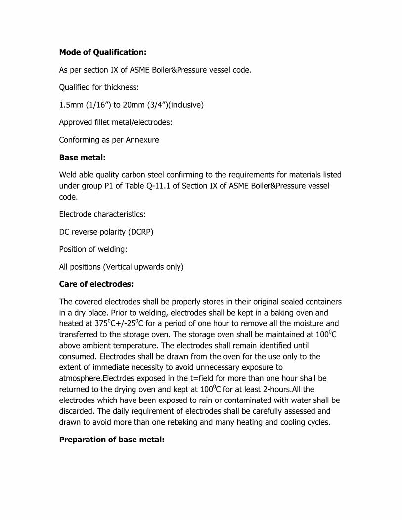
Mode of Qualification:
As per section IX of ASME Boiler&Pressure vessel code.
Qualified for thickness:
1.5mm (1/16”) to 20mm (3/4”)(inclusive)
Approved fillet metal/electrodes:
Conforming as per Annexure
Base metal:
Weld able quality carbon steel confirming to the requirements for materials listed
under group P1 of Table Q-11.1 of Section IX of ASME Boiler&Pressure vessel
code.
Electrode characteristics:
DC reverse polarity (DCRP)
Position of welding:
All positions (Vertical upwards only)
Care of electrodes:
The covered electrodes shall be properly stores in their original sealed containers
in a dry place. Prior to welding, electrodes shall be kept in a baking oven and
heated at 3750C+/-250C for a period of one hour to remove all the moisture and
transferred to the storage oven. The storage oven shall be maintained at 1000C
above ambient temperature. The electrodes shall remain identified until
consumed. Electrodes shall be drawn from the oven for the use only to the
extent of immediate necessity to avoid unnecessary exposure to
atmosphere.Electrdes exposed in the t=field for more than one hour shall be
returned to the drying oven and kept at 1000C for at least 2-hours.All the
electrodes which have been exposed to rain or contaminated with water shall be
discarded. The daily requirement of electrodes shall be carefully assessed and
drawn to avoid more than one rebaking and many heating and cooling cycles.
Preparation of base metal:
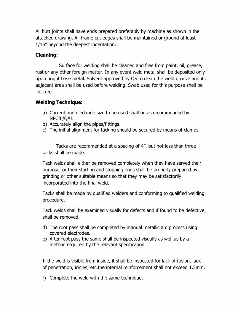
All butt joints shall have ends prepared preferably by machine as shown in the
attached drawing. All frame cut edges shall be maintained or ground at least
1/16” beyond the deepest indentation.
Cleaning:
Surface for welding shall be cleaned and free from paint, oil, grease,
rust or any other foreign matter. In any event weld metal shall be deposited only
upon bright base metal. Solvent approved by QS to clean the weld groove and its
adjacent area shall be used before welding. Swab used for this purpose shall be
lint free.
Welding Technique:
a) Current and electrode size to be used shall be as recommended by NPCIL/QAI.
b) Accurately align the pipes/fittings. c) The initial alignment for tacking should be secured by means of clamps.
Tacks are recommended at a spacing of 4”, but not less than three
tacks shall be made.
Tack welds shall either be removed completely when they have served their
purpose, or their starting and stopping ends shall be properly prepared by
grinding or other suitable means so that they may be satisfactorily
incorporated into the final weld.
Tacks shall be made by qualified welders and conforming to qualified welding
procedure.
Tack welds shall be examined visually for defects and if found to be defective,
shall be removed.
d) The root pass shall be completed by manual metallic arc process using covered electrodes.
e) After root pass the same shall be inspected visually as well as by a method required by the relevant specification.
If the weld is visible from inside, it shall be inspected for lack of fusion, lack
of penetration, icicles; etc.the internal reinforcement shall not exceed 1.5mm.
f) Complete the weld with the same technique.
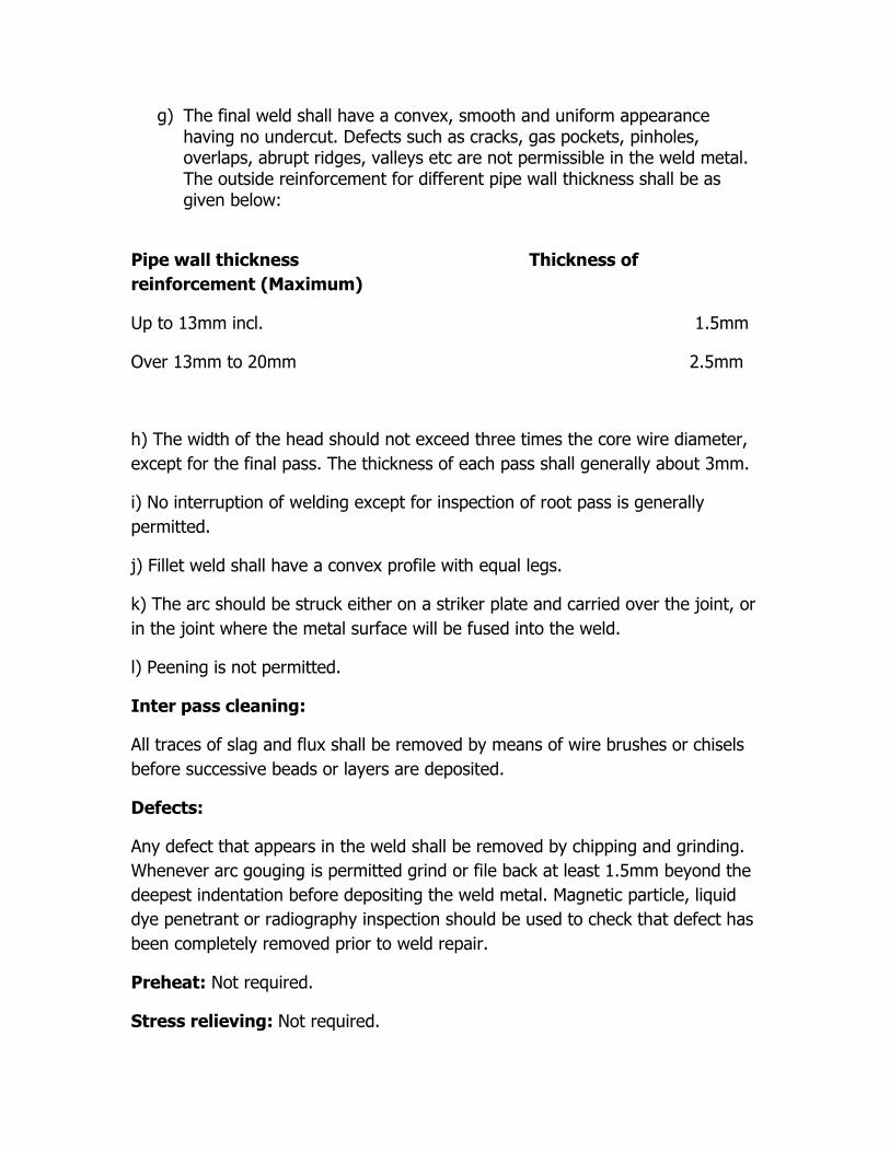
g) The final weld shall have a convex, smooth and uniform appearance having no undercut. Defects such as cracks, gas pockets, pinholes, overlaps, abrupt ridges, valleys etc are not permissible in the weld metal. The outside reinforcement for different pipe wall thickness shall be as given below:
Pipe wall thickness Thickness of
reinforcement (Maximum)
Up to 13mm incl. 1.5mm
Over 13mm to 20mm 2.5mm
h) The width of the head should not exceed three times the core wire diameter,
except for the final pass. The thickness of each pass shall generally about 3mm.
i) No interruption of welding except for inspection of root pass is generally
permitted.
j) Fillet weld shall have a convex profile with equal legs.
k) The arc should be struck either on a striker plate and carried over the joint, or
in the joint where the metal surface will be fused into the weld.
l) Peening is not permitted.
Inter pass cleaning:
All traces of slag and flux shall be removed by means of wire brushes or chisels
before successive beads or layers are deposited.
Defects:
Any defect that appears in the weld shall be removed by chipping and grinding.
Whenever arc gouging is permitted grind or file back at least 1.5mm beyond the
deepest indentation before depositing the weld metal. Magnetic particle, liquid
dye penetrant or radiography inspection should be used to check that defect has
been completely removed prior to weld repair.
Preheat: Not required.
Stress relieving: Not required.
Inspection: As per the approved QA plan (which has to be Submitted by the
contractor
and approved by MAPS Engineer)
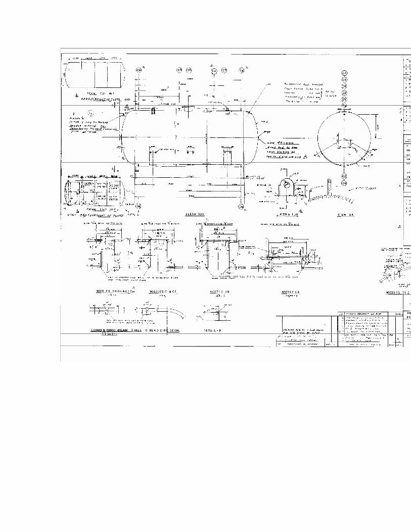
Technical Specification for Rubber Lining and Anticorrosive coating of
Bulk Soda Storage Tank
1. Reference Drawing No.M-1/71616/7577/DD/R-4.
Description of work:
Internal rubber lining has to be done to a thickness of 6mm. Cleaning and
surface preparation, rubber lining of tank internal surfaces as per IS 4682 (Part-
I): 1994 reaffirmed 1999 testing as per QA requirements to ensure bonding
strength and defect free lining, preparation of outside surface complete
including nozzles and corrosion protection FRP coating on the outer surface as
per IS no. 12643: 1983 reaffirmed 2000.
1. Design of Rubber lining: The material used should be of Neoprene
rubber. The rubber used should not be of Recycled or poor quality
material. It should satisfy the chemical and physical condition of the tank
and have non-stain properties. It should not deteriorate with continuous
contact of 33%. HCL. The rubber lining has to be done after sufficiently
satisfying each of the following steps.
i) Surface preparation by Grit / Sand blasting: The surface to be
rubber lined should be thoroughly cleaned free of duct, residues,
and debris left by either sand or fine metal ball grit blasting.
Immediately after grit blasting the surface to be protected against
rusting.
ii) Bonding the neoprene rubber sheet and Hot vulcanizing with
steam:
1. The rubber lining shall be bonded to the substrate. The adhesive system
shall be suitable for the type of rubber & for the service conditions. The
adhesive shall be applied to the primed substrate surface by brush, roller
or spray, any solvent in the adhesive being allowed to evaporate between
the successive coats or subsequent application of lining. The raw rubber
is to be tailored to fit the surface to be lined. Preshrinking and necessary
shall be carried out as first step.
2. The surface of the rubber, which will be lined on the metal, has to be
coated with rubber adhesive solution till it gets tackness. During the same
time the adhesive compound is applied on the prepared & allowed to tack.
Both rubber /metal & rubber / rubber surfaces coated with adhesive
solution shall be allowed to Dry sufficiently to achieve tackness. The type
of end joint shall be strapped Design. This Strapping joint shall be
suitably staggered to get effective smooth surface. The sheets before
laying shall be spark tested to confirm healthiness.
3. Fitting the lining sheets to the surface:
a) Exclusion of air-in the application of lining air shall be allowed to
escape between adjacent layers & metal.
b) Continuity of lining: When fitted all the sheets & strapped joints shall
be free from pinholes & other defects.
4. Lining shall be applied in double layer of each 3mm thick
5. Except when the sheets are prepared by extrusion, the sheets should be
prepared by calendaring, the number of plies for 6mm thick as per IS
4682 (part-I): 1994 is =4(four).
6. Vulcanizing: Steam vulcanization shall be adopted with outlets of tank
covered to reduce steam losses. Steam shall be injected unit
vulcanization temperature is achieved. This temperature shall be
maintenance until required time period. Vulcanization temperature & the
required time period shall be intimated for inspection.
iii) Inspection: The contractor has to offer the tank for inspection to
NPCIL/QAI at each of following stages.
1. Surface preparation.
2. Raw material – rubber with test certificate from NCPIL approved
laboratories.
3. Spark test on raw arterial.
4. Laying of joint – no patch permitted.
5. Hot steam vulcanization.
6. Hardness test = Hardness shall be =60 Shore A + or -5.
7. Spark – test after vulcanization to ensure defect free lining.
8. Overall visual.
External Anti-corrosive coating:
The outside surface has to be coated with anticorrosive coating of Epigen 4029
of 500micron thick.The complete tank outer surface including pipe spools,
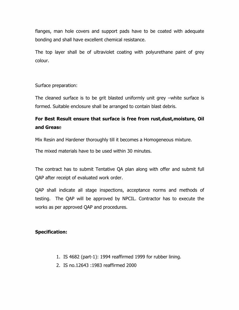
flanges, man hole covers and support pads have to be coated with adequate
bonding and shall have excellent chemical resistance.
The top layer shall be of ultraviolet coating with polyurethane paint of grey
colour.
Surface preparation:
The cleaned surface is to be grit blasted uniformly unit grey –white surface is
formed. Suitable enclosure shall be arranged to contain blast debris.
For Best Result ensure that surface is free from rust,dust,moisture, Oil
and Grease
Mix Resin and Hardener thoroughly till it becomes a Homogeneous mixture. The mixed materials have to be used within 30 minutes.
The contract has to submit Tentative QA plan along with offer and submit full
QAP after receipt of evaluated work order.
QAP shall indicate all stage inspections, acceptance norms and methods of
testing. The QAP will be approved by NPCIL. Contractor has to execute the
works as per approved QAP and procedures.
Specification:
1. IS 4682 (part-1): 1994 reaffirmed 1999 for rubber lining.
2. IS no.12643 :1983 reaffirmed 2000
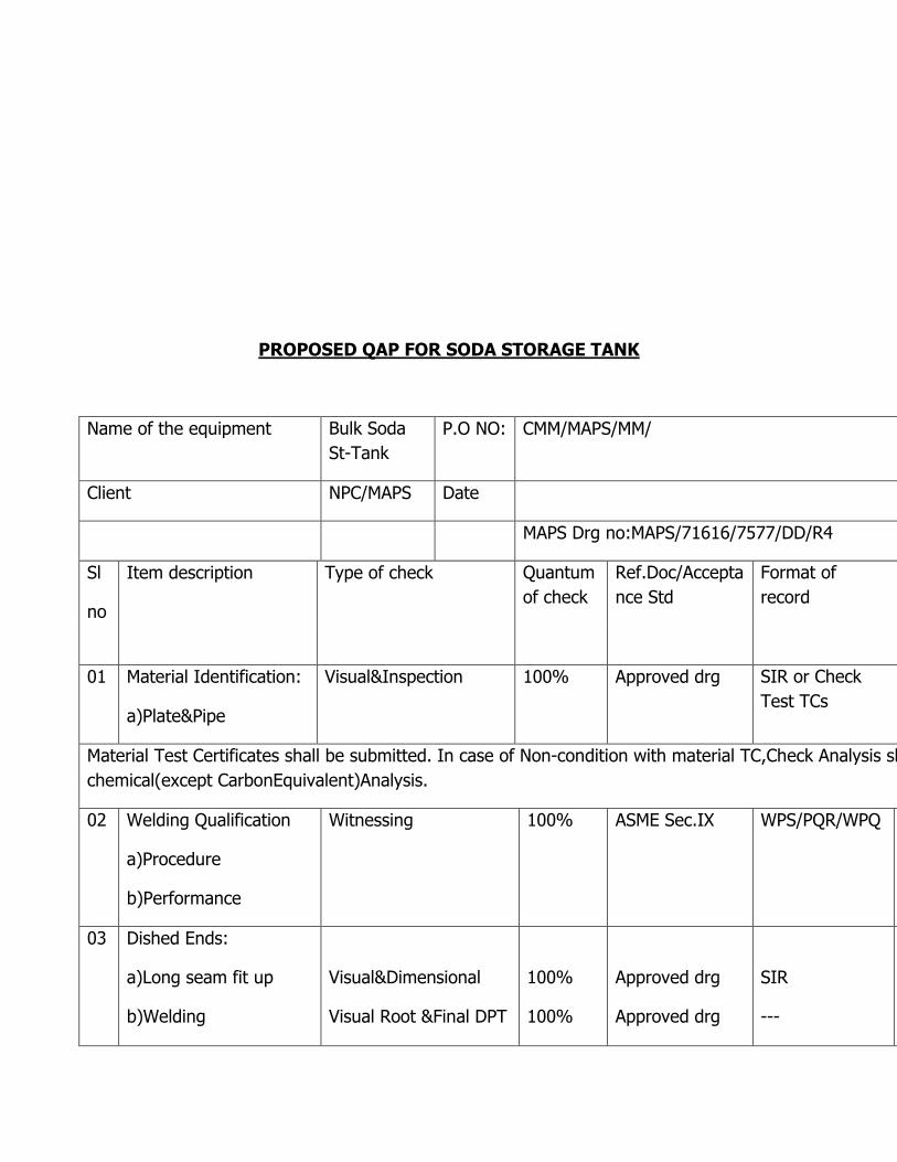
PROPOSED QAP FOR SODA STORAGE TANK
Name of the equipment Bulk Soda
St-Tank
P.O NO: CMM/MAPS/MM/
Client NPC/MAPS Date
MAPS Drg no:MAPS/71616/7577/DD/R4
Sl
no
Item description Type of check Quantum
of check
Ref.Doc/Accepta
nce Std
Format of
record
01 Material Identification:
a)Plate&Pipe
Visual&Inspection 100%
Approved drg
SIR or Check
Test TCs
Material Test Certificates shall be submitted. In case of Non-condition with material TC,Check Analysis shall be done for tensile and
chemical(except CarbonEquivalent)Analysis.
02 Welding Qualification
a)Procedure
b)Performance
Witnessing 100% ASME Sec.IX WPS/PQR/WPQ
03 Dished Ends:
a)Long seam fit up
b)Welding
Visual&Dimensional
Visual Root &Final DPT
100%
100%
Approved drg
Approved drg
SIR
---
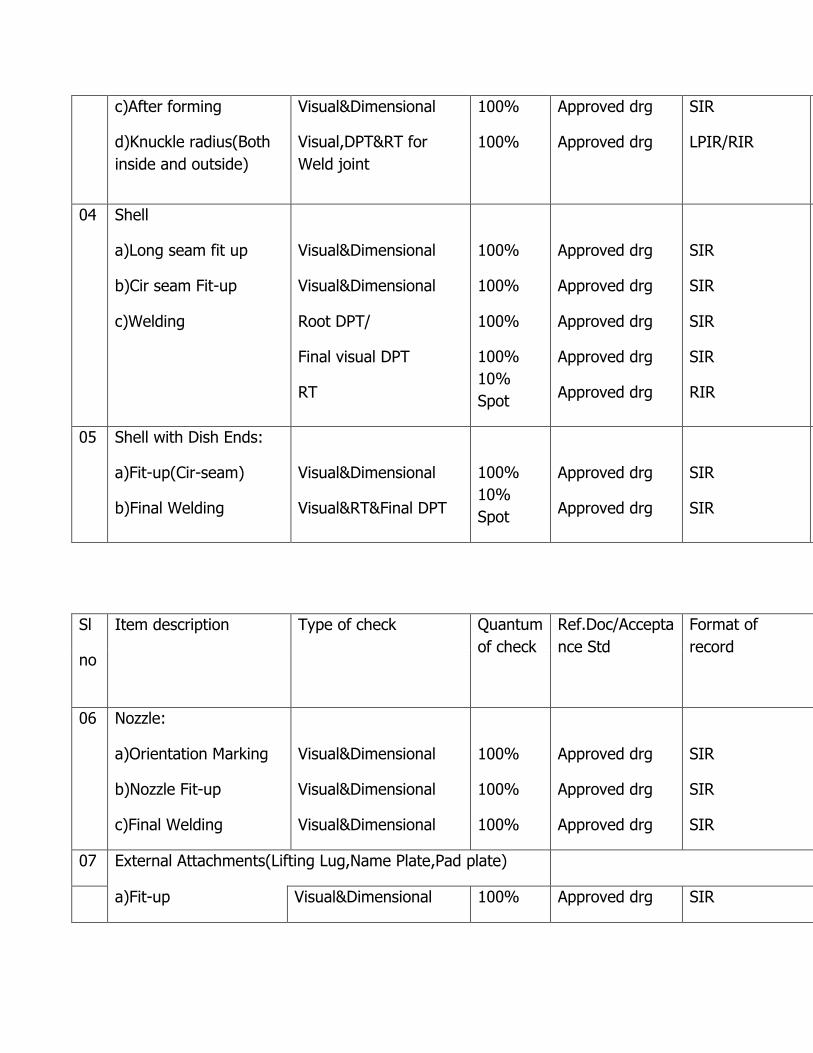
c)After forming
d)Knuckle radius(Both
inside and outside)
Visual&Dimensional
Visual,DPT&RT for
Weld joint
100%
100%
Approved drg
Approved drg
SIR
LPIR/RIR
04
Shell
a)Long seam fit up
b)Cir seam Fit-up
c)Welding
Visual&Dimensional
Visual&Dimensional
Root DPT/
Final visual DPT
RT
100%
100%
100%
100%
10%
Spot
Approved drg
Approved drg
Approved drg
Approved drg
Approved drg
SIR
SIR
SIR
SIR
RIR
05 Shell with Dish Ends:
a)Fit-up(Cir-seam)
b)Final Welding
Visual&Dimensional
Visual&RT&Final DPT
100%
10%
Spot
Approved drg
Approved drg
SIR
SIR
Sl
no
Item description
Type of check
Quantum
of check
Ref.Doc/Accepta
nce Std
Format of
record
06 Nozzle:
a)Orientation Marking
b)Nozzle Fit-up
c)Final Welding
Visual&Dimensional
Visual&Dimensional
Visual&Dimensional
100%
100%
100%
Approved drg
Approved drg
Approved drg
SIR
SIR
SIR
07 External Attachments(Lifting Lug,Name Plate,Pad plate)
a)Fit-up Visual&Dimensional 100% Approved drg SIR
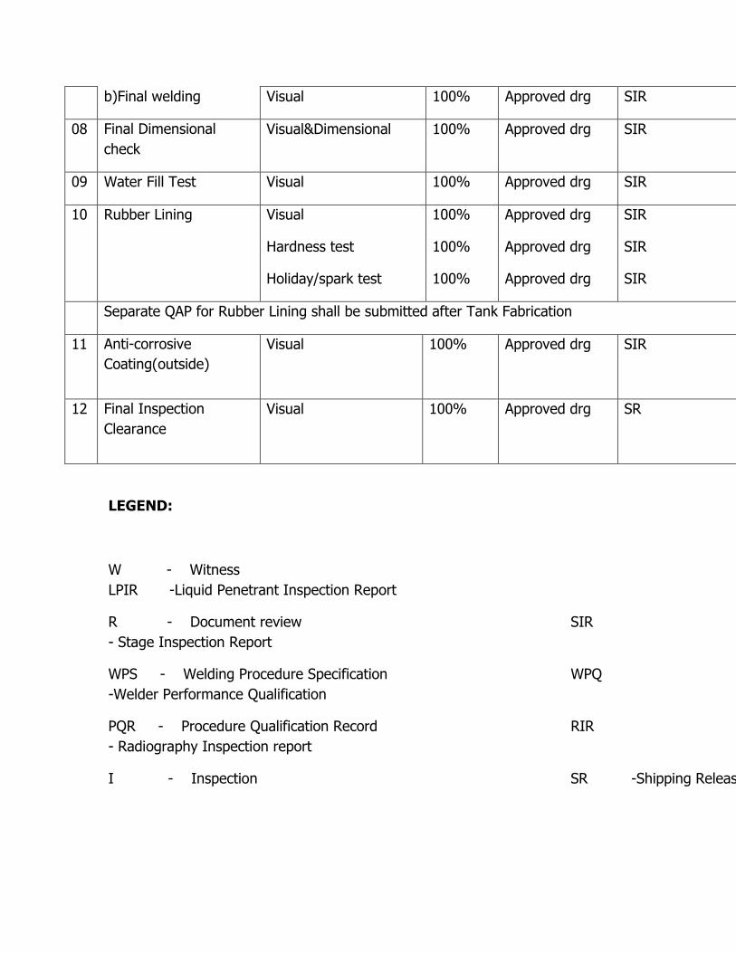
b)Final welding Visual 100% Approved drg SIR
08 Final Dimensional
check
Visual&Dimensional 100% Approved drg SIR
09 Water Fill Test Visual 100% Approved drg SIR
10 Rubber Lining Visual
Hardness test
Holiday/spark test
100%
100%
100%
Approved drg
Approved drg
Approved drg
SIR
SIR
SIR
Separate QAP for Rubber Lining shall be submitted after Tank Fabrication
11 Anti-corrosive
Coating(outside)
Visual 100% Approved drg
SIR
12 Final Inspection
Clearance
Visual 100% Approved drg
SR
LEGEND:
W - Witness
LPIR -Liquid Penetrant Inspection Report
R - Document review SIR
- Stage Inspection Report
WPS - Welding Procedure Specification WPQ
-Welder Performance Qualification
PQR - Procedure Qualification Record RIR
- Radiography Inspection report
I - Inspection SR -Shipping Release