Embed Size (px)
Citation preview
1 Sign & Seal of tenderer
Technical specification
Part – II

Sign & Seal of tenderer
Sub-Section - T1
Technical specification for excavation and
filling

3 Sign & Seal of tenderer
Section - T1
Technical specification for excavation and filling
1. Scope
1.1 This section of the specification covers the technical requirements for excavation and
filling for industrial plots in & around structures, buildings, pipes, foundations,
trenches, pits, drains, channels, cable ducts, underground facilities & similar works. It
also covers filling areas and plinths with selected materials, conveyance and disposal
of surplus soils and/or stacking them properly as directed by the Engineer.
1.2 The contractor shall be fully responsible for getting necessary permission from
government authorities to excavate soil from the sources mentioned in the tender and
should pay necessary seignerage charges to government authorities as per rules.
1.3 The Contractor shall be fully responsible for proper setting out of works, profiling in
excavation, stacking, etc., taking adequate safety measures etc. The Contractor shall
carry out all works meant within the intent of this specification even if not explicitly
mentioned herein. All work shall be executed to the satisfaction of the Engineer.
1.4 Existing trees, shrubs, any other plants, pole lines, fences, signs, monuments,
buildings, pipelines, drains, sewers, or other surface or subsurface systems/ drains/
facilities within or adjacent to the works being carried out which are not to be disturbed,
shall be protected from damage by the Contractor shall provide and install suitable
safeguards approved by the Engineer for this purpose.
1.5 During excavation, the Contractor shall take all necessary precautions against soil
erosion, water & environmental pollution and where required to undertake additional
works to achieve this objective. Before start of operations, the Contractor shall submit
to the Engineer for approval, his work plan and the procedure he intends to
follow for disposal of waste materials etc. and the schedule for carrying out temporary
and permanent control works. However, the approval of the Engineer to such plans
and procedures shall not absolve the Contractor of his responsibility for safe and
sound work.

4 Sign & Seal of tenderer
2. General requirements
2.1 The Contractor shall make his own surveying arrangements for locating the
coordinates and positions of all work and establishing the reduced levels (RL’s) at
these locations based on two reference grid lines and one benchmark, which will be
furnished by the Owner. The Contractor has to provide at site all the required survey
instruments, along with qualified surveyors, to the satisfaction of the Engineer so that
the work can be carried out accurately and according to the specification and
drawings.
2.2 The Contractor shall furnish all skilled and unskilled labour, plant, tools, tackle,
equipment, men, materials required for complete execution of the work in accordance
with the drawings and as described herein and/or as directed by the Engineer.
2.3 The Contractor shall control the grade in the vicinity of all excavations so that the
surface of the ground will be properly sloped or dyed to prevent surface water from
running into the excavated areas during construction.
2.4 All materials obtained from excavation shall remain owner’s property. All salvaged
materials of archeological importance or of value (in the opinion of the Engineer) shall
be segregated from the other materials and both stacked separately and in regular
manner at locations indicated by the Engineer.
2.5 Excavation shall include removal of trees including roots & organic remains,
vegetation, grass, bushes, shrubs, plants, poles, fences, etc. that are in the area to
be excavated as well as beyond the excavation line so as to ensure safety of the
excavated side slopes, and of men and equipment operating in the area. Before start
of excavation work, joint measurements of ground level shall be taken after cleaning
all grass, vegetation, etc.
2.6 Excavation shall include the removal of all materials required to execute the work
properly and shall be made with sufficient clearance as decided by the Engineer to
permit the placing and setting of forms, inspection and completion of all works to the
satisfaction of the Engineer for which the excavation was done.

5 Sign & Seal of tenderer
2.7 Wherever reference is made to ‘drawings’ in this specification it shall mean the latest
issue of the approved drawings.
3. Codes and standards
3.1 All standards, specifications, acts, and codes of practice referred to herein shall be
the latest editions including all applicable official amendments and revisions.
3.2 In case of conflict between this specification and those (IS standards, codes etc.)
referred to herein (in para 3.3) the former shall prevail.
3.3 Some of the relevant Indian standards, Acts and Codes are referred to here below:
IS:383 Specification for coarse and fine aggregates from
natural sources for concrete
IS:2720 (Part-II, IV to VIII, XIV, XXI,
XXIII, XXIV, XXVII to XXIX, XL)
Methods of tests for soils - determination of water
content etc.
IS:3764: Safety code for excavation work
IS:4081: Safety code for blasting and related drilling
operations
IS:4701: Code of Practice for earth work on canals
IS:9759: Guide lines for Dewatering during construction.
IS:10379: Code of practice for field control of moisture and
compaction of soils for embankment and
subgrade.
IS:3812 Pulverized fuel ash – specification part 2 for use
as admixture in cement mortar and concrete
4. Excavation
4.1 Excavation in all types of soils, soft and disintegrated rock (ordinary rock), and hard
rock shall be done up to the required level. Excavation shall also include breaking of
existing concrete RCC, Masonry work, tar and bitumen surfaces, and paving works

6 Sign & Seal of tenderer
etc. In case blasting is required the same shall be subject to the approval of Engineer.
Sides and bottoms of excavation shall be cut sharp and true to line and level.
Undercutting shall not be permitted. When machines are used for excavation, the last
300 mm before reaching the required level shall be excavated manually or by such
equipment that soil at the required final level will be left in its natural condition.
Suitability of strata (at the bottom of excavations) for laying the foundation thereon
shall be determined by the Engineer.
4.2 Excavation for foundations shall be to the bottom of lean concrete and as shown on
drawings or as directed by the Engineer. The bottom of all excavations shall be
trimmed to required levels and when excavation is carried below such levels, by error,
it shall be brought back to specified level by filling with concrete of nominal mix 1:3:6
/ 1:4:8 (cement & Fly ash (20% replacement ratio of cement with fly ash):
coarse sand : 20mm down aggregates) as directed by the Engineer.
4.3 The Contractor shall ascertain for himself the nature of materials to be excavated and
the difficulties, if any, likely to be encountered in executing this work. Cofferdams,
Sheeting, shoring, bracing, maintaining suitable slopes, draining etc.
shall be provided and installed by the Contractor, to the satisfaction of the Engineer.
4.4 All excavation for installation of underground facilities, such as piping, sewer lines,
drain lines, etc shall be open cuts. For deep and huge excavations and in other
excavations, if required by the Engineer, the Contractor shall submit for Engineer’s
approval (as already mentioned under Clause 1.5) an “Excavation scheme” showing
the methodology to be adopted for excavation in order to maintain the stability of side
slopes, means for ensuring safety of existing facilities nearby, dewatering as required
etc. However, the Contractor shall be fully responsible for the scheme irrespective of
any approvals granted. Benching shall be provided for deeper excavation wherever
required.
4.5 When excavation requires bracing, sheeting or shoring etc., the Contractor shall
submit drawings to the Engineer, showing arrangements and details of proposed
installation. The Contractor shall also furnish all supporting calculations as called for
and shall not proceed until he has received written approval from the Engineer.

7 Sign & Seal of tenderer
However, the responsibility for adequacy of such bracing, sheeting, shoring etc. will
rest with the Contractor, irrespective of any approval of the Engineer. All precautions
shall be taken while excavations near existing structures are to be carried out till the
backfilling is completed.
4.6 The Contractor shall have to constantly pump out any water collected in excavated
pits and other areas due to rain water, ground water, springs etc. and maintain dry
working conditions at all times until the excavation, placement of reinforcement,
shuttering, concreting, backfilling is completed. The Contractor shall remove all
slush/muck from the excavated areas to keep the work area dry. Sludge pumps, if
required, shall be employed by the Contractor for this purpose.
4.7 The Contractor shall remove all materials arising from excavations from the vicinity of
the work either for direct filling, stacking and subsequent filling or for ultimate disposal
as directed by the Engineer. In no case shall the excavated soil be stacked within a
distance of 1.5m from the edge of excavation or one third the depth of excavation
whichever is more. Material to be used for filling shall be kept separately as directed
by the Engineer.
5. Filling
5.1 Materials
a) Materials to be used for filling purposes shall be stone, sand or other inorganic
materials and they shall be clean and free from shingle, salts, organic, large roots
and excessive amount of sod. Lumps concrete or any other foreign substances
which could harm or impair the strength of the substructure in any manner. All
clods shall be suitably broken to small pieces. When the material is mostly rock
boulders, these shall be broken into pieces not larger than 150mm size. Sand
used for filling shall be clean, medium grained and free from impurities. Fines
less than 5 microns shall not be more than 20%. In any case, the materials to
be used for filling purposes shall have the prior written approval of the Engineer.
b) If excavated materials are to be used for filling, then the Contractor shall select
the materials from the stockpile, load and transport this material and execute the

8 Sign & Seal of tenderer
filling. This shall include excavation of earth which may become hard due to
laying in stack yard for a long period of time.
c) In case the materials have to be brought from pits/quarries, then it shall be the
Contractor’s responsibility for identification of such quarry areas, obtaining
approval for their use from concerned authorities, excavation/quarrying, loading
and carriage of such material, unloading and filling at specified locations. The
Contractor shall pay any fees, royalties etc. that may have to be paid for
utilization of borrow areas.
5.2 Filling procedure
a) After completion of foundation, footings, walls and other construction below the
elevation of the final grades, and prior to filling, all temporary shoring, timber, etc.
shall be sequentially removed and the excavation cleaned of all trash, debris &
perishable materials. Filling shall begin only with the written approval of the
Engineer. Also, areas identified for filling shall be cleared of all soft pockets,
vegetation, bushes, slush etc. In case of plinth and similar filling the ground shall
be dressed and consolidated by ramming and light rolling.
b) Fill materials shall not be dropped directly upon or against any structure or facility
where there is danger of displacement or damage. Filling shall be started after
the concrete/masonry has fully set and shall be carried out in such manner so as
not to cause any undue lateral thrust on any part of the structure.
c) All space between foundation (concrete or masonry) and the sides of excavation
shall be filled to the original surface after making allowance for settlement. Fill
shall be placed in horizontal layers not exceeding 200mm loose thickness. Each
layer shall be watered and compacted with proper moisture content & with such
equipment as may be required to obtain a compaction / density as specified.
Trucks or heavy equipment for depositing or compacting fill shall not be used
within 1.5 metres of building walls, piers or other facilities which may be damaged
by their weight or operations. The methods of compaction shall be subject to the
approval of the Engineer. Pushing of earth for filling shall not be adopted under
any circumstances.

9 Sign & Seal of tenderer
d) Fill adjacent to pipes shall be free of stones, concrete, etc. and shall be hand
placed and compacted uniformly on both sides of the pipe and where practicable
upto a minimum depth of 300mm over the top of pipes. While tamping around
the pipes, care should be taken to avoid unequal pressure.
e) Filling shall be accurately finished to line, slope, cross section and grade as
shown on the drawings. Finished surface shall be free of irregularities and
depressions and shall be within 20mm of the specified level.
f) Where filling with stone from excavated materials is required, as per design and
functional requirements, it shall be from broken pieces of boulders. At first a
75mm thick cushion of selected earth shall be laid over which the 200mm thick
graded stones shall be laid in loose layers of 200mm and then the interstices
filled with properly graded fine materials consisting of selected earth brought from
borrow areas. Each layer shall be watered and compacted to the required density
as per design and functional requirements before the next layer is laid. However,
no cushion shall be required where filling is over non-rocky surface.
g) Where clean stone fill is required as per design and functional requirements it
shall consist of clean selected stone metal of 40mm nominal size. It shall be laid
in layers not exceeding 150mm (loose) and lightly tamped before the next layer
is laid. No compaction shall be required for this type of stone filling.
5.3 Compaction
a) Where compaction of 90% Standard Proctor Density is called for, such
compaction shall be by mechanical means but the contractor may be permitted
to adopt manual means only if the Engineer finds that the desired compaction is
achievable in the field.
b) Where compaction to 95% Standard Proctor Density is called for, it shall be by
mechanical means only. Where access is possible, compaction shall be 12
tonne rollers smooth wheeled, sheep foot or wobbly wheeled and directed by the
Engineer. A smaller weight roller may be permitted by the Engineer in special
10 Sign & Seal of tenderer
cases, but in any case not less than 10 passes of the roller will be accepted for
each layer. Each layer shall be wetted or the material dried by aeration to a
moisture content of 3-5% above the Optimum Moisture Content to be determined
by Contractor. Each layer shall be watered, rammed and compacted to the
density as specified in the Schedule of Quantities.
c) For compacting each sand layer, water shall be sprayed over it to flood it and it
shall be kept flooded for 24 hours to ensure maximum compaction.
Vibrocompactors shall also be used if necessary to obtain the required degree
of compaction. Any temporary works required to contain sand under flooded
condition shall also be undertaken. The surface of the consolidated sand shall
be dressed to required levels or slope.
d) After the compacted fill has reached the desired level, the surface shall be
flooded with water for 24 hours, allowed to dry and then rammed and
consolidated to avoid any settlement, at a later date. The compacted surface
shall be properly shaped, trimmed and consolidated to an even gradient or level.
All soft spots shall be excavated, filled and consolidated.
e) The degree of compaction of compacted fill in place will be subject to tests in
accordance with relevant Indian Standards as desired by the Engineer. As the
work progress, the Contractor shall provide the necessary facilities to make such
tests. If any test indicates that the compaction achieved is less than the required
as per design and functional requirements degree of compaction, the Engineer
may require all fill placed subsequent to the last successfully test to be removed
and re-compacted by the Contractor. Compaction procedure shall be amended
as necessary to obtain satisfactory results.
f) When semi-compacted fill is required as per design and functional requirements
by the Engineer, the Contractor shall fill up such areas with available earth from
stockpiles or borrow pits or directly from excavation without special compaction
except that obtained by moving trucks, etc.
6. Sampling testing and quality control

11 Sign & Seal of tenderer
6.1 General
a) The Contractor shall carry out all sampling and testing in accordance with the
relevant Indian Standards and/or International Standards and shall conduct such
tests as are called for by the Engineer. Where no specific testing procedure is
mentioned, the tests shall be carried out as per the prevalent accepted
engineering practice to the directions of the Engineer. Tests shall be done in the
field and at a laboratory approved by the Engineer and the Contractor shall
submit to the Engineer, the test results in triplicate within three days after
completion of a test. The Engineer may, at his discretion, waive some of the
stipulations given below, for small and unimportant operations.
b) Work found unsuitable for acceptance shall be removed and replaced by the
Contractor. The work shall be redone as per specification requirement and to the
satisfaction of the Engineer.
c) Only as a very special case and that too in non-critical areas, the Engineer may
accept filling work which is marginally unacceptable as per the criteria laid down.
For such accepted work, payment shall be made at a reduced rate prorate to the
compaction obtained against that stipulated.
6.2 Quality assurance programme
The Contractor shall submit and finalize a detailed field Quality Assurance Programme
within 30 days from the date of award of the Contract according to the requirements
of the specification. This shall include setting up of a testing laboratory, arrangement
of testing apparatus/equipment, deployment of qualified/experienced manpower,
preparation of format for record, Field Quality Plan, etc. On finalized field quality plan,
the owner shall identify customer hold prints beyond which work shall not proceed
without written approval from the Engineer.
6.3 Frequency of sampling and testing including the methods for conducting the tests are
given in Table-1. The testing frequencies set forth are the desirable minimum and the
Engineer shall have the full authority to carry out or call for tests as frequently as he

12 Sign & Seal of tenderer
may deem necessary to satisfy himself that the materials and works comply with the
appropriate specifications.
6.4 Acceptance criteria
Following acceptance criteria shall be followed:
a) All individual samples collected and tested should pass without any deviation
when only one set of sample is tested.
b) For re-test of any sample two additional samples shall be collected and tested,
and both should pass without any deviation.
c) Where a large number of samples are tested for a particular test than 9 samples
out of every 10 consecutive samples tested shall meet the specification
requirement.
d) Tolerance on finished levels for important filling areas at approved intervals shall
be + 20 mm. However, for an unimportant area, tolerance upto + 57 mm shall
be acceptable at the discretion of the Engineer. However, these tolerances shall
be applicable for localized areas only.
Table 1: Frequency of sampling and testing
Sl.
No.
Nature of test /
characteristics Methods of test No. of samples &
frequency of test Remarks
I. Suitability of fill
materials
(a) Grain size analysis IS:2720 (Part-IV) One in every 2000 Test for and sand
Sl.
No.
Nature of test /
characteristics Methods of test No. of samples &
frequency of test Remarks
Cum. for each type and
each source of fill
material subject to a
minimum of

13 Sign & Seal of tenderer
(b) Liquid limit and plastic
limit IS:2720 (Part-V) two samples Test for soil
(c) Shrinkage limit IS:2720 (Part-VI) One in every 5000
cum. for each type
The frequency of
Test shall be
(d) Free sweel index IS:2720 (Part-XL) And each source of fill
materials. increased
depending on type
of soil
(e) Chemical Analysis IS:2720
i. Organic matter Part XXII One in every 5000 Cum
for each type and each
source of
Test for sand and
soil.
ii. Calcium carbonate Part XXIII Fill materials.
iii. pH Part XXVI
iv. Total soluble sulphate Part XXVII
II. Standard proctor test IS:2720 (Part VII) One in every 2000 cum.
for each type and each
source of fill
materials
Test for soil for
determining
optimum moisture
content, Dry
Density etc.
III. Moisture content of Fill
before compaction. IS:2720 (Part II) -do- Test for soil
IV. Degree of compaction of
fill (i) For foundation filling,
one for every ten
foundations for each
Test for soil
(a) Dry density by core
cutter method IS:2720 (Part
XXIX) Compacted layer.
However, each layer for
location of important
and heavily loaded
or
Dry density in place by sand
displacement method IS:2720 (Part
XXVIII) Foundations resting on
fill shall be tested.
Sl.
No.
Nature of test /
characteristics Methods of test No. of samples &
frequency of test Remarks
(ii) For area filling one
for every 1000 Sqm.
area for each
compacted layer.

14 Sign & Seal of tenderer
(b) Relative density index IS:2720 (Part XIV) -do- (i) & (ii) Test for sand
(c) Dry density by proctor
needle penetration Standard Practice Random checks to be
carried out for each
compacted layer in
addition to tests
mentioned under IV (a)
above.
Test for soil
15 Sign & Seal of tenderer
Sub-Section - T2 Technical
specification for properties, storage
and handling of common building
materials

16 Sign & Seal of tenderer
Section - T2
Technical specification for properties, storage and handling of common
building materials
1. Scope
1.1 The scope of this section of the specification is to specify the properties, storage and
handling of common building materials namely, coarse aggregates, cement, water,
sand masonry units, reinforcement and structural steel.
1.2 Properties of the materials in general have been discussed. Specific requirements of
the materials have been stipulated separately under specification for relevant items of
work.
2. General requirements
2.1 The work shall include, providing of all necessary plants and equipment, providing
adequate engineering supervision and technical personnel, skilled and unskilled labour
etc. as required to carry out the entire work as directed by the Engineer to his complete
satisfaction.
2.2 All materials proposed for use in the work shall conform to the requirements laid down
in this section, and also subject to the approval of the Engineer. After specific materials
have been accepted, the source of supply of such materials shall not be changed
without prior approval of the Engineer.
Approval of any material by the Engineer shall not relieve the Contractor of his responsibility,
for the requisite quality and performance of the material used.
2.3 Any material considered to be sub-standard, or not upto satisfaction of the Engineer,
shall not be used by the Contractor and shall be removed from the site immediately.

17 Sign & Seal of tenderer
2.4 Representative samples shall be procured by the Contractor and submitted to the
Engineer, for approval before bulk procurement. The representative samples shall be
retained by the Engineer for future comparison and reference.
3. Codes and standards
3.1 In the event that state, city or other local governmental bodies have requirements more
stringent than those set forth in this specification, the former shall govern.
3.2 All applicable standards, acts, specifications, codes of practice, handbooks, referred to
herein shall be the latest editions, including all official amendments and revisions. In
case of discrepancy between this specification and those referred to herein, this
specification shall govern.
Any special materials used, but not covered here, shall conform to relevant Indian Standards,
if any, or as specified by the Engineer for any special purpose.
3.3 Some of the applicable Indian standards, codes are referred to here below :
IS:226 Specification for structural steel (standard quality).
IS:269 Specification for ordinary Portland cement, 33 grade.
IS:383 Specification for coarse and fine aggregates from natural sources for
concrete.
IS:432 Specification for mild steel and medium tensile steel bars and
(Parts 1 & 2) hard-drawn steel wires for concrete reinforcement.
IS:455 Specification for Portland slag cement.
IS:712 Specification for building limes.
IS:1077 Specification for common burnt clay building bricks.

18 Sign & Seal of tenderer
IS:1077
Specification for Burnt clay bricks/Fly ash bricks.
IS:1127 Recommendations for dimensions and workmanship of natural
building stones for masonry work.
IS:1129
Recommendation for dressing of natural building stones.
IS:1489 Specification for Portland pozzolana cement
(Part-I) Fly ash based
(Part-II) Calcined clay based
IS:1542
Specification of sand for plaster.
IS:1566
Specification hard-drawn steel wire fabric for concrete reinforcement.
IS:1597 Code of Practice for construction of Stone masonry, rubble stone
masonry.
IS:1786 Specification for high strength deformed bars for concrete
reinforcement.
IS:2062
Specification for hot rolled medium and high tensile structural steel.
IS:2116
Specification for sand for masonry mortars.
IS:2386
Testing of aggregates for concrete.(Part I to VIII)
IS:3495
Methods of test of Burnt clay bricks/Fly ash bricks (Part-I to IV)
IS:4031
Methods of physical tests for hydraulic cement.
IS:4032
Methods of chemical analysis of hydraulic cement.
IS:4082 Recommendations on stacking and storage of construction materials at
site.

19 Sign & Seal of tenderer
IS:7969 Safety code for handling and storage of building materials.
IS:8112 High strength ordinary portland cement.
IS:8500 Medium and high strength structural steel.
IS:12269 43/53 grade ordinary Portland cement.
IS:12330 Sulphate resisting Portland cement.
IS:12600 Portland cement, low heat.
IS:12894 Fly Ash Lime Bricks - specification.
IS: 3812-2 Specification for pulverized fuel ash for use as admixture in cement mortar
and concrete
4. Burnt clay bricks
4.1 Burnt clay bricks, for general masonry work, shall conform to IS: 1077 and for
face brick work, shall conform to IS: 2691. Fly ash lime bricks shall conform to
IS:12894
4.2 Bricks for general masonry work shall be table moulded/machine made, well
burnt without being vitrified, of uniform size, shape, having sharp edges and
cherry red colour. These shall be free from cracks, flaws or nodules of free lime
and shall emit clear ringing sound (metallic sound) when struck. These shall not
show any signs of efflorescence either when dry or subsequent to soaking in
water. Fractured surface shall show uniform texture free from girts, lumps, holes
etc.
4.3 Unless otherwise specified, minimum compressive strength shall correspond to
class designation 75 as per IS: 107 with a minimum crushing strength of 75
kg/sq.cm. for general masonry work. However, for non-load bearing walls, bricks
20 Sign & Seal of tenderer
pavements, etc. bricks of class designation 50 shall only be used, wherever
specified or shown on the drawings. Water absorption after 24 hours immersion
shall not exceed 20% by weight for common bricks and 15% for face bricks.
4.4 On the basis of finish and dimensional tolerance, the bricks shall be classified as
sub class A and B. Dimensional tolerance shall not exceed 3% and 8% of the
size, of common bricks for sub-class A & B respectively and 3% for face bricks.
All bricks shall have rectangular faces and sharp straight edges. Maximum
permissible chip page for the face bricks shall be 6mm at the edges and 10mm
for corners. The face bricks shall show no efflorescence after soaking in water
and drying in the shade.
4.5 The size of the bricks used shall be either modular size as per IS:1077 or locally
available conventional size as approved by the Engineer.
4.6 Each brick shall have the manufacturer’s identification mark clearly marked on
the frog. The colour and texture of face bricks shall be limited to the range of
samples submitted. Any brick not found upto the satisfaction of the Engineer
shall be removed immediately from site by the Contractor.
5. Fly ash bricks
5.1 Fly ash bricks (cement bonded) shall be locally made. Bricks shall have smooth
rectangular faces with sharp and square corners. Bricks shall be hand or
machine moulded and shall be made from the admixture of suitable good quality
of fly ash, sand and cement as per the composition mentioned below :
FLY ASH : 50-60%
SAND : 32-40%
CEMENT : 8-12%
5.2 The fly ash bricks will be as per latest relevant IS code. The bricks will be of
dimension as per standard clay brick, suitable for making 230mm thick full brick
wall, 115mm thick half brick wall and 75mm thick minor partition walls, as
applicable, as per drawing/specification/BOQ. A maximum tolerance of (+/-)

21 Sign & Seal of tenderer
2mm shall be allowed as the manufacturing tolerance. The bricks shall have frog
of 100 mm in length 40 mm in width and 10 to 20 mm deep of one of its flat sides.
The bricks when tested in accordance with the procedure laid down in IS 3495 (part 2)
1992 after immersion in cold water for 24 hrs. Water absorption shall be within 13-15%
by weight. Similarly, the porosity of the fly ash bricks shall be within 12-20%. The bricks
shall have a minimum crushing strength of 80 Kg/Sqcm.
5.3 Fly ash bricks, for general masonry work, shall conform to IS:2212-1991
5.4 Unless otherwise specified, minimum compressive strength shall correspond to
class designation 80 as per IS: 107 with a minimum crushing strength of 80
kg/sq.cm. For general masonry work. However, for non-load bearing walls, bricks
pavements, etc. bricks of class designation 50 shall only be used, wherever
specified or shown on the drawings. Water absorption after 24 hours immersion
shall not exceed 20% by weight for common bricks and 15% for face bricks.
5.5 On the basis of finish and dimensional tolerance, the bricks shall be classified as
sub class A and B. Dimensional tolerance shall not exceed 3% and 8% of the
size, of common bricks for sub-class A & B respectively. All bricks shall have
rectangular faces and sharp straight edges. Maximum permissible chip page for
the face bricks shall be 6mm at the edges and 10mm for corners. The face bricks
shall show no efflorescence after soaking in water and drying in the shade.
5.6 The size of the bricks used shall be either modular size as per IS:1077 or locally
available conventional size as approved by the Engineer.
5.7 Each brick shall have the manufacturer’s identification mark clearly marked on
the frog. The colour and texture of face bricks shall be limited to the range of
samples submitted. Any brick not found upto the satisfaction of the Engineer
shall be removed immediately from site by the Contractor.
6. Stones

22 Sign & Seal of tenderer
6.1 All stones shall be from approved quarries. These shall be hard, tough, durable,
compact grained, uniform the texture and colour and free from decay, flaws,
veins, cracks and sand holes. The surface of a freshly broken stone shall be
bright, clean
and sharp and hall show uniformity of texture, without loose grains and free from any
dull, chalky or earthy appearance. Stone with round surface shall not be used.
6.2 Stones showing mottled colours shall not be used for face work. A stone shall
not absorb more than 5% of its weight of water after 24 hours immersion. The
type of stone shall be as specified or shown on drawings and/or as instructed by
the Engineer. Stones used for masonry work shall conform to IS:1597 (Part – I)
No soft stone shall be used for masonry or for filling purpose.
6.3 Any stone not found upto the satisfaction of Engineer shall be removed
immediately from site by the Contractor.
7. Lime
7.1 Lime shall be stone lime and it shall conform to IS: 712. Hydrated lime shall be
mixed with water to form a putty. This shall be stored with reasonable care to
prevent evaporation of water for atleast 24 hours before use. Quick lime shall
be slaked with enough water to make a cream and then stored with reasonable
care to prevent evaporation of water for atleast seven days before use. Type of
lime to be used for different purposes such as concreting, plastering, white
washing etc. shall be according to the satisfaction made hereunder :
Class – A Eminently hydraulic lime used for structural purposes.
Class – B Semi-hydraulic lime used for masonry mortars, lime concrete and plaster
undercoat
Class – C Fat lime used for finishing coat in plastering, white washing, composite
mortars, etc. and with addition of pozzolanic materials for masonry
mortar.

23 Sign & Seal of tenderer
Class – D Magnesium/dolomite lime used for finishing coat in plastering,
whitewashing, etc.
Class – E Kankar lime used for masonry mortar.
Class – F Siliceous dolomite lime used for undercoat and finishing coat of plaster
8. Cement and Fly ash
8.1 Cement shall be ordinary Portland cement, 43/53 grade conforming to IS 8112/12269.
The Engineer may permit the use of Portland pozzolana cement conforming to IS: 1489
or Portland slag cement conforming to IS: 455 or sulphate resistant cement confirming
to IS 12330 as per the specific site condition. However, any lower grade of OPC, PPC
and PSC should never be mixed with higher grade cement.
8.2 Fly ash is generated by burning of coal in coal fired power plants. It has the
characteristic of pozzolonic additive to cement. Continuous research studies by various
engineering research laboratories revealed its varied usefulness as an additive for
enhancing the various qualities of concrete including its workability, strength and
durability if handled and cared properly. Partial replacement of cement with fly ash in
concrete save much of the energy required for production of OPC and also facilitates
the economical disposal of millions of tons of fly ash.
At present most of the fly ash blended cements commercially produced in India has 18
to 25% fly ash by weight and addition of fly ash to this extent has a beneficial effect on
the workability and economy of concrete. It has been found that in order to improve the
other qualities of concrete like resistance of sulfate attack and thermal cracking, larger
percentage of fly ash is to be used in concrete.
Indian standard specification No. 3812-2003, Specification for Pulverized Fuel Ash, Part
2: For Use as Admixture in Cement Mortar and Concrete [CED 2: Cement and
Concrete] covers the extraction and the physical and chemical requirements of
pulverized fuel ash for use as admixture in cement mortar and concrete. Fly ash
confirming to this standard shall be used in place of cement.

24 Sign & Seal of tenderer
The chemical, physical requirements and testing of fly ash shall be in accordance with
the IS 3812-2003
9. Water
9.1 Water used for cement concrete, mortar, plaster, grout, curing, washing of coarse
aggregate, soaking of bricks, etc. shall be clean and free from injurious amount of oil,
acids, alkalis, organic matters or other harmful substances in such amounts that may
impair the strength or durability of the structure. Potable water shall generally be
considered satisfactory for all masonry and concrete works, including curing. The
Contractor shall carry out necessary tests in advance to prove the suitability of the water
proposed to be used. As a guide, the following concentrations represent the maximum
permissible values :
a. To neutralize 200 ml sample of water, it should not require more than 2ml of 0.1
normal NaOH.
b. To neutralize 200 ml sample of water, it should not require more than 10ml of 0.1
normal HCL.
c. Percentage of solids shall not exceed the following :
i) Organic 0.02 ii) Inorganic 0.30 iii)
Sulphates 0.05 iv) Chlorides 0.10
v) Suspended matter 0.20
10. Aggregates
10.1 Aggregates mean both coarse and fine inert materials used in the preparation of
concrete. Aggregates shall consist of natural sands, crushed stone and gravel from a
source known to produce satisfactory aggregate for concrete and shall be chemically
inert, hard, strong, durable against weathering, of limited porosity and free from such
quantities of deleterious materials as may cause corrosion of reinforcement or may
impair the strength and / or durability of the concrete. Total percentage of all deleterious
materials, including coal, lignite, clay lumps, materials finer than 75 microns, soft

25 Sign & Seal of tenderer
fragments and shale but excluding mica shall not exceed 5%. However, for crushed fine
aggregate, total percentage of coal and lignite and clay lumps, shall
be limited to 2%. Both coarse and fine aggregates shall conform to IS:383 for concrete,
shotcreting etc. unless otherwise mentioned.
10.2 Sample of aggregates for mix design and determination of their suitability shall be sent
to the laboratory well in advance in scheduled placing of concrete. Sampling, testing,
and interpretation of test results shall be subject to the approval of the Engineer.
Aggregates shall be properly graded.
11. Sand
11.1 Sand shall be hard, durable, clean and free from adherent coatings of organic matter
and shall not contain clay balls or pellets. The sand shall be free from impurities such
as iron pyrites, alkalis, salts, coal, mica, shale, or other laminated materials, in such
forms or quantities as to affect adversely the hardening, strength, durability or
appearance on mortar, plaster, etc. or to cause corrosion of any metal in contact with
such mortar, plaster etc. In no case, the cumulative percentage of Impurities in sand
shall be more than 5% by weight. All sand shall be properly graded. Unless otherwise
directed by the Engineer, sand for masonry mortars shall conform to IS: 2116 and sand
for plaster shall conform to IS: 1542. Sand, when used as fine aggregate, in concrete,
shall conform to IS:383. For filling, medium grained sand (having fines less than 75
microns not exceeding 20%) shall be used.
12. Reinforcement steel, structural steel (including embedded steel) and wire mesh
12.1 Billet:- (Primary steel)
A semi-finished product obtained by forging or rolling, usually square and not exceeding
125 x 125 mm in cross section with rounded corners and is intended for further
processing into suitable finished product by forging or re-rolling.
Steel shall be manufactured by open hearth, electric, duplex, basic oxygen or a
combination of these processes. In case any other process is employed by the
manufacturer, prior approval of the purchaser should be obtained.

26 Sign & Seal of tenderer
The ladle analysis of the material when analyzed in accordance with the various parts
of IS: 228, shall be confirmed with IS: 8056-1976- Table 1 (Chemical composition).
Table 1 Chemical Composition (As per IS: 8056-1976 clauses 3.1 & 6.1)
Constituent Percent
Carbon 0-45 to 0.80
Silicon 0.15 to 0.35
Manganese 0.40 to 1.00
Sulphur, Max 0.050
Phosphorus, Max 0.050
In case of continuous cast billets, the billet analysis shall be taken as ladle analysis.
Permissible variation in case of product analysis from the limits specified in IS:
80561976 clause-6.1 shall be as follows:
Constituent Variation Over the Specified Maximum or
Under the Minimum Limits in %
Carbon 0.03
Silicon 0.03
Manganese 0.04
Sulphur, Max 0.005
Phosphorus, Max 0.005
Note - Variations shall not be applicable both over and under the specified limits in
several determinations in a heat.
SAMPLING
At least one ladle sample analysis shall be taken per cast.
If required, the samples for product analysis shall be prepared by forging or rolling down
to 30-mm round section

27 Sign & Seal of tenderer
In case of wire rods the test piece size shall be the size of wire rods.
Drilling shall be taken from the sample representing two-thirds, half and one-third of
height from bottom of the billet separately.
In case of continuous cast billets and billets produced from ingots of masses 3 tonnes
and more, the sample may be taken from anywhere from the billets.
FREEDOM FROM DEFECTS
The billets and continuous cast billets shall be free from harmful defects, such as pipe,
laminations, segregation, inclusions and cracks.
Subject to agreement between the purchaser and the manufacturer, the billets and
continuous cast billets may be supplied with suitable surface dressing.
billets shall either be supplied free from harmful segregation, piping, cracks, inclusions,
and blow-hole by appropriate top and bottom discard and dressing or supplied with
suitable surface dressing only, without top and bottom discard if agreed to between the
purchaser and the manufacturer, to ensure the requirements of freedom from defects
specified in the relevant product specifications.
If agreed to between the purchaser and the manufacturer the following tests may be
carried out from the samples prepared under IS: 8056-1976
DIMENSIONS
The size and tolerance of billets shall be subject to agreement between the purchaser
and the manufacturer. However, the nominal sizes of billets generally supplied as per
guidance given in IS: 8056-1976
The preferred sizes of billets shall be 50, 63, 7!, 80, 90, 100 and 125 mm.

28 Sign & Seal of tenderer
The sizes other than those specified may be supplied by agreement between the
purchaser and the manufacturer.
A tolerance of the billets shall be confirmed with IS: 8056-1976
The ends of ingots and billets shall be painted with a suitable colour code conforming
to IS: 2049-1963.
Each ingot and billet shall be legibly stamped or painted with the cast number, grade
and the name or trademark of the manufacturer.
The material may also be marked with the IS1 Certification Mark.
12.2 All steel for reinforcement shall be clean and free from loose mill scales, dust, loose rust,
oil, grease, paint or other harmful matters which may affect its bond with concrete. Mild
steel and medium tensile steel bars and hard drawn steel wire for concrete
reinforcement shall conform to grade-1 of IS:432 (Part-1). High strength deformed steel
bars shall conform to grade Fe 415 of IS: 1786. All steel bars shall be of tested quality.
Actual grade and type steel, to be used, shall be as specified or shown on drawings.
12.3 Structural steel (including embedded steel) shall be straight, sound, and free from twists,
cracks, flaws, laminations and all other defects. Structural steel shall be of tested quality
conforming to IS: 226, IS: 2062 or IS: 8500. These shall be free from lamination defects.
Grade and type of steel to be used shall be as specified.
12.4 Hard drawn steel wire fabric shall conform to IS: 1566. Wire fabric shall be electrically
cross welded.
13. Storage and handling of materials
13.1 Generally, all materials shall be stacked and stored by the Contractor as described in
IS: 4082 unless otherwise mentioned and in a manner affording convenient access for
identification and inspection at all times. The storage area and arrangements shall be
subject to the approval of the Engineer. Any material rendered unserviceable during the
29 Sign & Seal of tenderer
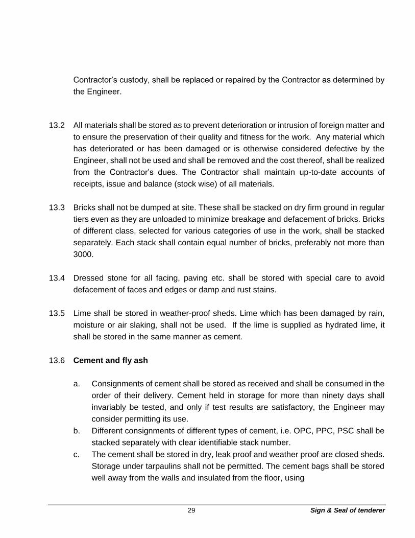
Contractor’s custody, shall be replaced or repaired by the Contractor as determined by
the Engineer.
13.2 All materials shall be stored as to prevent deterioration or intrusion of foreign matter and
to ensure the preservation of their quality and fitness for the work. Any material which
has deteriorated or has been damaged or is otherwise considered defective by the
Engineer, shall not be used and shall be removed and the cost thereof, shall be realized
from the Contractor’s dues. The Contractor shall maintain up-to-date accounts of
receipts, issue and balance (stock wise) of all materials.
13.3 Bricks shall not be dumped at site. These shall be stacked on dry firm ground in regular
tiers even as they are unloaded to minimize breakage and defacement of bricks. Bricks
of different class, selected for various categories of use in the work, shall be stacked
separately. Each stack shall contain equal number of bricks, preferably not more than
3000.
13.4 Dressed stone for all facing, paving etc. shall be stored with special care to avoid
defacement of faces and edges or damp and rust stains.
13.5 Lime shall be stored in weather-proof sheds. Lime which has been damaged by rain,
moisture or air slaking, shall not be used. If the lime is supplied as hydrated lime, it
shall be stored in the same manner as cement.
13.6 Cement and fly ash
a. Consignments of cement shall be stored as received and shall be consumed in the
order of their delivery. Cement held in storage for more than ninety days shall
invariably be tested, and only if test results are satisfactory, the Engineer may
consider permitting its use.
b. Different consignments of different types of cement, i.e. OPC, PPC, PSC shall be
stacked separately with clear identifiable stack number.
c. The cement shall be stored in dry, leak proof and weather proof are closed sheds.
Storage under tarpaulins shall not be permitted. The cement bags shall be stored
well away from the walls and insulated from the floor, using

30 Sign & Seal of tenderer
d. Planks etc. to avoid contact with moisture. The cement shall be stacked in easily
countable stacks and in a place of easy access so as to facilitate proper inspection
and removal on a first in first out basis. Not more than 15 bags shall
be stacked in any tier to prevent lumping up under pressure. However, in stacks
more than 8 bags high, the cement bags shall be arranged alternately lengthwise
and crosswise so as to tie the stacks together and minimize the danger of toppling
over. The cement bags shall be gently kept to avoid leakage of cement from the
bags. Substandard or partially set cement shall be immediately removed from the
site as soon as it is detected.
e. The contractor shall make his own arrangements for the storage of adequate
quantity of cement. Cement in bulk may be stored in bins or silos which will provide
adequate protection against dampness, contamination, etc. The bins or silos, shall
be cleaned periodically.
f. Pulverized fuel ash (Fly ash) shall be stored in accordance with the
recommendation given in IS 4082. Additionally, during bulk storage, the fly ash
should be suitably covered to avoid getting airborne.
g. Supplies of pulverized fuel ash (Fly ash) may be made in bulk in suitable quantities
or in bags (jute, jute-laminated, multiple paper or polyethylene lined) bearing the
net mass (may be 15 kg, 30 kg, 300 kg, 600 kg as agreed by the
Contractor)
h. Pulverized fuel ash in bulk storage for more than 6 months or in bags for more
than-3 months after completion of tests, may be re-tested before use and standard.
May be rejected, if it fails to conform to any requirements of this standard.
i. Pulverized fuel ash may be rejected if it does not comply with any of the
requirements stipulated in IS 3812 Part 2 of 2003
13.7 Coarse and fine aggregates/sand
a. Coarse and fine aggregates shall be stacked separately. Contamination with
foreign materials and earth during storage and while heaping the materials shall
be avoided. Coarse aggregates shall be stacked in layers not exceeding 120 cm
in height such that corning and segregation do not occur. Each layer shall cover
the entire area of the stockpile before succeeding layers are placed. Segregated
aggregates from stockpile shall be rejected.

31 Sign & Seal of tenderer
b. Aggregates shall be stored on brick soling or an equivalent platform so that they
do not come in contact with dirt, clay, grass or any other injurious substance, at
any stage. For lifting aggregates from stockpiles, rakers shall be used. Aggregates
of different sizes shall be kept in separate and easily measurable stacks. If so
desired by the Engineer, aggregates from different source shall be stacked
separately with proper care to prevent intermixing.
13.8 Reinforcement and Structural Steel (including steel required for embedment)
a. Reinforcement and structural steel (including steel required for embedment) shall
be stored consignment wise and size wise, off the ground by at least 150mm and
protected by the suitable cover, or as desired by the Engineer. The steel shall be
protected from rusting, oil grease and distortions. The reinforcing steel shall be
coated with cement wash before stacking to prevent scale and rust, in areas having
accelerating corrosion effect like marine atmosphere. The stacks shall be easily
measurable. Steel needed for immediate use only shall be removed from storage.
Fabricated steel shall be carefully stored to prevent damage, distortion, corrosion
and deterioration.
b. Reinforcement shall be stored according to the diameter, grade and length in such
a place as to permit easy approach for inspection and identification.
c. The area shall be such that water does not accumulate and reinforcement does
not get distorted or corroded. It shall not be stacked directly over ground or near
any harmful materials. It shall be cleaned of excessive rust before use.
d. Steel plates of different specifications shall be stacked separately. Steel of IS: 2062
and IS: 8500 quality shall be given a grade wise, distinctive identification mark.
Passage and space between the stacks shall be sufficient for rigging operations.
14. Testing
14.1 All materials provided by the Contractor shall be tested for conformity of the
specification and the test results shall be submitted to the Engineer for acceptance. In
addition to above, the Contractor shall carry out the relevant tests at site as specified
under different items of work.

32 Sign & Seal of tenderer
Section - T3
Technical specification for cast-in-situ concrete and allied works
Section 1 - Common requirement
1. Scope
1.1 The work shall include providing of materials, all necessary plant and equipment,
providing adequate engineering supervision and technical personnel, skilled and
unskilled labour, etc. as required to carry out the entire work as indicated on the
drawings and/or described herein subsequently and/or as directed by the Engineer.
1.2 The Contractor shall carry out all works meant within the intent of this specification even
if not explicitly mentioned herein. All works shall be executed to the satisfaction of the
Engineer.
1.3 This specification is divided into 13 sections. The Section – 1 deals with common
requirements and the other 12 sections deal with specifications for 12 different
items/activities. The stipulations contained in Section-1, ‘Common Requirements’
shall form a part of the specifications of 12 different items/activities described in section
2 to 13.
All these eight sections are as follows:
Section - 1 Common requirement
Section - 2 Cast-in-Situ Concrete
Section - 3 Reinforcement
Section - 4 Formwork and staging
Section - 5 Embedded parts
Section - 6 Foundation bolt assembly
Section - 7 Shotcreting
Section - 8 Grouting
Section - 9 Encasement of steel structures/elements

33 Sign & Seal of tenderer
Section - 10 Joints in Concrete
Section - 11 Water proofing/damp proofing of underground concrete structures.
Section - 12 Dismantling/Demolishing works-RCC and PCC.
Section - 13 Cement Additives/Admixtures in concrete.
Section - 10 Joints in Concrete
Section - 11 Water proofing/damp proofing of underground concrete structures.
Section - 12 Dismantling/Demolishing works-RCC and PCC. Section
- 13 Cement Additives/Admixtures in concrete.
2. General
2.1 Any approval, instructions, permission, checking, review, etc. whatsoever by the
Engineer, shall not relieve the Contractor of his responsibility and obligation
regarding adequacy, correctness, completeness, safety strength, quality,
workmanship, etc.
2.2 The Contractor shall make his own surveying arrangements for locating the
coordinates and positions of all work and establishing the reduced levels (RLs)
at these locations, based on two reference grid lines and one bench mark, which
will be furnished by the Owner. The Contractor has to provide at site, faction of
the Engineer so that the work can be carried out accurately and according to the
specifications and drawings.
3. Codes and standards
3.1 All applicable standards, specifications, etc. and codes of practice shall generally
be the latest editions, including all applicable official amendments and revisions.
A complete set of all these documents shall generally be available at site, with
the Contractor.
3.2 All work shall be carried out as per the stipulations contained in various sections
of these specifications and the latest Indian Standards, Acts, Codes and best
practices.

34 Sign & Seal of tenderer
3.3 In case of conflict between the stipulations contained in various sections of these
specifications and stipulations of Indian Standards, Codes, etc. the requirements
of stipulations contained in various sections of these specifications, shall prevail
over that of Indian Standards, Codes, etc.
3.4 Some of the applicable Indian Standards, Codes, etc. are referred to here below:
IS:73 Specification for paving bitumen
IS:2062 Specification for structural steel
IS:269 Specification for Ordinary Portland cement, 33 grade.
IS:280 Specification of mild steel wire for general engineering purposes
IS:383 Specification for coarse and fine aggregates from natural sources for
concrete.
IS:432 Specification for mild steel and medium tensile steel (parts I & II) bars and
hard drawn steel wire for concrete reinforcement.
IS:455 Specification for Portland slag cement
IS:456 Code of practice for plain and reinforced concrete.
IS:457 Code of general construction of plain & reinforced concrete for dams
& other massive structures.
IS:516 Method of test for strength of concrete
IS:650 Specification for standard sand for testing of cement
IS:702 Specification for industrial bitumen

35 Sign & Seal of tenderer
IS: 816 Code of practice for use of metal arc welding for general
construction in mild steel.
IS: 1199
Method of sampling and analysis of concrete
IS: 1200
Method of measurement of building (Part-II and civil engineering
works. V, VIII, XVIII)
IS: 1367 Technical supply conditions for threaded steel fasteners.
IS: 1489 Specification for Portland-pozzolana cement (Part-I) Fly ash
based (Part-II) Calcined clay based
IS: 1566 Specification for Hard-drawn steel wire fabric for concrete
reinforcement.
IS: 1609 Code of practice for laying damp proof treatment using bitumen
felts.
IS: 1786 Specification for high strength deformed steel bars and wires for
concrete reinforcement
IS: 1791
General requirements for batch type concrete mixers.
IS: 1838(Part 1)
Specification for preformed fillers for expansion joints in concrete
pavements and structures (non extruding and resilient type)
IS: 2204
Code of practice for construction of reinforced concrete shell roof.
IS: 2210
Criteria for the design of reinforced concrete shell structures and
folded plates.
IS: 2386
Methods of test of aggregates for (Parts concrete I to VIII)

36 Sign & Seal of tenderer
IS: 2438 Specification for roller pan mixer
IS: 2502 Code of practice for bending and fixing of bars for concrete
reinforcement.
IS: 2505
General requirements for concrete vibrators, immersion type.
IS: 2506
General requirements for concrete vibrators, screed board type.
IS: 2514
Specification for concrete vibrating tables.
IS: 2571
Code of practice for laying in-situ cement-concrete flooring.
IS: 2645
Specification for Integral cement water proofing compounds.
IS: 2722
Specification for portable swing weighs batchers for concrete.
(Single and double bucket type)
IS: 2750
Specification for Steel scaffoldings
IS: 2751
Code of practice for welding of mild steel plain and deformed bars
for reinforced concrete structures.
IS: 3025
Methods of sampling and test waste water.
IS: 3067
Code of practice for general design details and preparatory work for
damp proofing & water proofing of buildings.
IS: 3150
Specification for hexagonal wire netting for general purposes.
IS: 3366
Specification for Pan Vibrators.
IS: 3370 Code of practice for concrete (Part I structures for the storage of to
IV) liquids)

37 Sign & Seal of tenderer
IS: 3384
Specification for bitumen primer for use in water proofing & damp
proofing.
IS: 3414
Code of practice for design and installation of joints in buildings.
IS: 3550
Methods of test for routine control for water used in industry.
IS: 3558 Code of practice for use of immersion vibrators for consolidating
concrete.
IS: 3696
Safety code for scaffolds (Part I ladders & II)
IS: 3812-2 Specification for pulverized fuel ash for use as admixture in cement
mortar and concrete
IS: 4014
Code of practice for steel tubular scaffolding (Parts I & II)
IS: 4031 Methods for physical tests for hydraulic cement.
IS: 4130
Safety Code for demolition of buildings.
IS: 4326
Code of practice for earthquake resistant design and construction
of buildings.
IS: 4461
Code of practice for joints in surface hydro-electric power stations.
IS: 4656
Specification for form vibrators for concrete.
IS: 4925
Specification for batching and mixing plant.
IS: 4990 Specification for plywood for concrete shuttering work.
IS: 4995 Criteria for design of reinforced concrete bins for the storage of
granular and powdery materials. (Parts I & II)

38 Sign & Seal of tenderer
IS: 5121
Safety code for piling and other deep foundations.
IS: 5256
Code or practice for sealing joints in concrete lining on canals.
IS: 5525 Recommendations for detailing of reinforcement in reinforced
concrete work.
IS: 5624
Specification for foundation bolts.
IS: 6461
Glossary of terms relating to cement concrete.
IS: 6494
Code of practice for water proofing of underground water reservoirs
and swimming pools.
IS: 6509
Code of practice for installation of joints in concrete pavements.
IS: 7193
Specification for glass fiber base coal-tar pitch and bitumen felts.
IS: 7293
Safety code for working with construction machinery.
IS: 7861
Code of practice for extreme weather concreting (Parts I&II)
IS: 9012 Recommended practice for Shotcreting.
IS: 9103
Specification for admixtures for concrete.
IS: 9417
Recommendations for welding cold-worked steel bars for reinforced
concrete construction.
IS: 9595 Recommendations for metal-arc welding of carbon and carbon
manganese steels.
IS: 10262
Recommended guidelines for concrete mix design.

39 Sign & Seal of tenderer
IS: 11384 Code of practice for composite construction in structural steel and
concrete.
IS: 12118 Specification for two-part poly sulphide.
IS: 12200 Code of practice for provision of water stops at transverse
contraction joints in masonry and concrete dams.
IS: 12269 43/53 Grade ordinary Portland cement.
IS: 12600 Portland cement, low heat.
SP: 23 Handbook of concrete mixes
SP: 24 Explanatory Handbooks on IS: 456-1978
SP: 34 Handbook on concrete reinforcement and detailing.
4. Sampling, testing and quality assurance
4.1 Facilities required for sampling materials, concrete, reinforcement, formwork,
etc. in the field and in the laboratory shall be provided by the Contractor. The
Contractor shall carry out all sampling and testing in accordance with the relevant
Indian Standards and/or International Standards and this specification. Where
no specific testing procedure is mentioned, the tests shall be carried out as per
the prevalent accepted engineering practice to the directions of the Engineer.
Tests shall be done in the field in the presence of the Engineer or his authorized
representative and at a laboratory, approved by the Engineer, and the Contractor
shall submit to the Engineer the test results in triplicate within three days after
completion of any test.
4.2 The Contractor shall maintain records of all inspection and testing, which shall
be made available to the Engineer. The Engineer at his discretion, may waive
some of the stipulations for small and unimportant concreting operations and
other works.

40 Sign & Seal of tenderer
4.3 Work found unsuitable for acceptance shall be removed and replaced by the
Contractor. The work shall be redone as per specification requirements and to
the satisfaction of the Engineer at no extra cost to the Owner.
4.4 Quality assurance programme
a) The Contractor shall submit and finalize a detailed field Quality Assurance
Programme within 30 days from the date of award of the contract, before
commencement of work at site, according to the requirements of the
specification. This shall include setting up of a testing laboratory,
arrangement of testing apparatus/equipment, deployment of
qualified/experienced manpower, preparation of format for record, field
quality plan, etc. On finalized field quality plan, the Owner shall identify,
customer hold points, beyond which work shall not proceed without written
approval from the Engineer. The testing apparatus/ equipment installed in
the field laboratory shall be calibrated /corrected by the authorized persons
as frequently as possible to give accurate testing results.
b) Frequency of sampling and testing, etc. and Acceptance Criteria are given
in respective sections. However, the testing frequencies set forth are the
desirable minimum and the Engineer shall have the full authority to carry
out or call for tests as frequently as he may deem necessary to satisfy
himself that the materials and works comply with the appropriate
specifications.

41 Sign & Seal of tenderer
Section 2 - Cast-in-situ concrete
5. Scope
This section of the specification deals with plain or reinforced cement concrete for
general use and in structures and covers the requirements for concrete, materials,
their properties, storage, handling, grading, mix design, strength and quality, pouring
at all levels, testing, casting, protecting, curing, finishing, etc.
6. General requirement
6.1 The provision of IS: 456 shall be followed as general guidance, along with all other
relevant Indian Standards, unless otherwise specifically mentioned.
6.2 Before starting a concrete pour, the Contractor shall obtain the approval of the
Engineer on a ‘Pour Card’ maintained for this purpose. He shall obtain complete
instructions about the materials and proportions, water cement ratio, etc. to be used,
slump/workability, number of test cubes/samples to be taken, type of finishing to done,
any admixture to be added, any limitation on size of pour and location for interruption
of a pour in case of premature stopping of pour, etc.
6.3 The mixers and weigh-batchers, shall be maintained in clean and serviceable
condition. Accuracy of all equipment shall be periodically checked. All concrete shall
be mixed in mechanically operated batch mixers complying with IS: 1791 and these
shall be of approved make, with suitable provision for correctly controlling the water
delivered to the drum. Weigh batchers shall conform to IS: 2722 and shall be capable
of controlling the weights to within one percent of the desired value.
6.4 The Contractor’s procedures for casting massive concrete sections (as noted on the
drawings or as identified by the Engineer) shall take account of the release of the heat
of hydration, drying shrinkage behavior. The procedures shall be such that cracking
or loss of strength of the concrete from these effects is prevented. At least one week
before commencing the construction of any massive concrete section, the Contractor
shall submit, for approval of the Engineer, detailed proposals for placing

42 Sign & Seal of tenderer
the concrete together with supporting calculations to demonstrate the suitability of the
methods.
7. Materials
7.1 In general, all the materials used in the manufacture of concrete shall be in
accordance with the Technical specification for properties, storage and handling of
common building materials, (vide module C2) which shall be deemed to form a part of
this specification.
7.2 The Engineer shall have the right to inspect the sources of materials, method of
procurement and storage of materials, method of procurement and storage of
materials, quality control procedures, etc.
7.3 Cement
The cement used shall be the Ordinary Portland cement conforming to IS:269 or Portland
Pozzolana cement conforming to IS:1489 or Portland slag cement conforming to
IS:455 or any other type of cement, specified in IS:456 with the prior approval of the
Engineer. However, any special type of cement such as High strength cement or
sulphate resisting cement, may be used under special circumstances.
7.4 Aggregates
a) For reinforced concrete work, aggregates conforming to IS:383 & IS:2386 having
a maximum size of 20 mm shall be used. For certain reinforced concrete works,
aggregates having a maximum size other than 20 mm size shall also be used as
called for in the drawings. However, for lean concrete provided as mud mat below
structural concrete, maximum size upto 40 mm shall be used.
b) Aggregates (coarse or fine) with a specific gravity below 2.6 shall not be used
without special permission of the Engineer. Machine-made sand will be
acceptable provided the constituent (rock/gravel) is sound, hard, dense and is
acceptable to the Engineer. Sand, natural gravel and crushed rock shall be

43 Sign & Seal of tenderer
prepared for use by such screening or washing, or both, as necessary to remove
all objectionable foreign matter.
c) Type of aggregates: Petro graphic examination shall be carried out to ascertain
the structure and rock type of aggregate including presence of strained quartz
and other reactive minerals. Moreover, in case the coarse aggregate sample is
of composite nature, the proportions (by weight) of different rock types in the
composite sample and petrographic evaluation of each rock should also be
ascertained. While determining different rock type is in the composite sample,
special emphasis should be given on identification of known reactive rocks like
chalcedony, opal etc. and procedure laid down in IS:2430 for sampling of
aggregates may be followed. The sample should not contain weathered rock and
reduced to required quantity by quartering and coning.
The results of petro graphic test, shall be submitted to the Engineer. The
Engineer shall review the results on consultation with some specialist agencies,
if required, to determine potential activity of the aggregate (siliceous minerals)
which may lead to reaction of silica in aggregate with the alkalis of cement. In
additional, potential of some aggregate like lime stone to residual expansion due
to repeated temperature cycle is also to be reviewed. Further, the Contractor
shall submit the results of Alkali aggregates reactivity carried out as per IS: 2386
(Pt. VII).
In case of any apprehension about the properties of the aggregate, the Engineer
shall ask the Contractor to send samples of coarse and fine aggregate to any of
the established research laboratory including National Council for, Cement and
Building Materials (NCB), Ballabgarh for further testing. However, the Owner
shall fix the agency and bear the cost of such testing.
In case, it is established from the tests that the aggregates contain reactive silica
which would react with alkalis of the cement, the Contractor shall be asked to
change the source of supply of the aggregate and take additional measures as
suggested. In case aggregates indicate residual expansion, under repeated
temperature cycle test, the material shall not be used for concreting of equipment
foundations, which are likely to be subjected under repeated temperature cycle.

44 Sign & Seal of tenderer
The Contractor shall use different type of aggregate as approved by the
Engineer.
7.5 Admixtures
Admixtures in concrete for promoting workability, improving strength, entraining air for
similar purposes may be used only after the written permission from the Engineer is
obtained. These shall be free from injurious amount of chloride, etc. Addition of
admixtures should not reduce the specified strength or durability of concrete and
should not have detrimental effect on reinforcement. The admixtures shall conform to
IS: 9103 and shall be of proven make and from a reputed manufacturer. Calcium
chloride as accelerating admixture is not permitted to be used other than in mass
concrete works. The Contractor shall produce latest test results carried out at
approved Government Test Houses for the approval of the Engineer, before use
details of admixtures have been covered under Section - 13.
8. Water
8.1 Water used for mixing and curing shall be clean and free from injurious amounts of
oils, acids, alkalis, sugar, organic materials or other substances that may be
deleterious to concrete or steel. Potable water is generally considered satisfactory for
mixing concrete. The maximum permissible values of impurities shall be as given in
clause no. 4.3 of IS: 456-1978.
8.2 In case of doubt regarding development of strength, the suitability of water for making
concrete shall be ascertained by the compressive strength and initial setting time tests
specified in IS: 456.
8.3 Average 28 days compressive strength of at least three 150 mm concrete cubes
prepared with water proposed to be used shall not be less than 90% of the average
strength of three similar concrete cubes prepared with distilled water. The cubes shall
be prepared, cured and tested in accordance with IS: 456.
8.4 The initial setting time of a concrete test block made with the appropriate cement and
the water proposed to be used shall not be less than 30 minutes and shall not differ
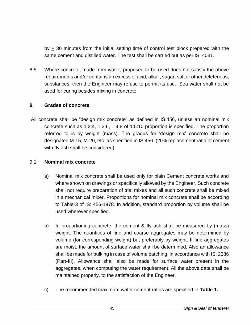
45 Sign & Seal of tenderer
by + 30 minutes from the initial setting time of control test block prepared with the
same cement and distilled water. The test shall be carried out as per IS: 4031.
8.5 Where concrete, made from water, proposed to be used does not satisfy the above
requirements and/or contains an excess of acid, alkali, sugar, salt or other deleterious,
substances, then the Engineer may refuse to permit its use. Sea water shall not be
used for curing besides mixing in concrete.
9. Grades of concrete
All concrete shall be “design mix concrete” as defined in IS:456, unless an nominal mix
concrete such as 1:2:4, 1:3:6, 1:4:8 of 1:5:10 proportion is specified. The proportion
referred to is by weight (mass). The grades for ‘design mix’ concrete shall be
designated M-15, M-20, etc. as specified in IS:456. (20% replacement ratio of cement
with fly ash shall be considered):
9.1 Nominal mix concrete
a) Nominal mix concrete shall be used only for plain Cement concrete works and
where shown on drawings or specifically allowed by the Engineer. Such concrete
shall not require preparation of trial mixes and all such concrete shall be mixed
in a mechanical mixer. Proportions for nominal mix concrete shall be according
to Table-3 of IS: 456-1978. In addition, standard proportion by volume shall be
used wherever specified.
b) In proportioning concrete, the cement & fly ash shall be measured by (mass)
weight. The quantities of fine and coarse aggregates may be determined by
volume (for corresponding weight) but preferably by weight. If fine aggregates
are moist, the amount of surface water shall be determined. Also an allowance
shall be made for bulking in case of volume batching, in accordance with IS: 2386
(Part-III). Allowance shall also be made for surface water present in the
aggregates, when computing the water requirement. All the above data shall be
maintained properly, to the satisfaction of the Engineer.
c) The recommended maximum water cement ratios are specified in Table 1.

46 Sign & Seal of tenderer
Table 1: Recommended water - Cement ratio
Nominal mix concrete Quantity of water per
50 Kg. of cement (max.)
1:5:10 60 litres
1:4:8 45 litres
Nominal mix concrete Quantity of water per
50 Kg. of cement (max.)
1:3:6 34 litres
1:2:4 32 litres
d) Nominal mix concrete 1:5:10 shall correspond to grade M5, 1:4:8 shall
correspond to grade M7.5, 1:3:6 to grade M10 and 1:2:4 to grade M15 of IS:456.
e) If Nominal mix concrete made in accordance with specified proportions does not
yield the specified strength of the corresponding grade and fails to satisfy the
requirements of “acceptance criteria for concrete” as specified in IS:456. Such
concrete shall be treated in the following manner:
i) In case the Engineer is satisfied that lower strength of concrete is
attributed to material and workmanship of the Contractor, then such
concrete shall be replaced by concrete of specified strength. The Engineer
may however, also accept such lower strength concrete but such lower
strength concrete shall be classified as belonging to the appropriate lower
grade proportion.
ii) In case the Engineer is satisfied that lower strength of concrete is not
attributable to the Contractor, he may direct in writing to increase the
cement content to obtain specified strength. Such extra cement shall also
be considered for reconciliation purposes. The use of richer mix shall be
continued until the Engineer instructs otherwise.
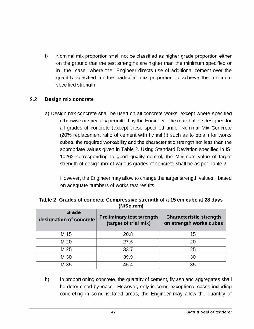
47 Sign & Seal of tenderer
f) Nominal mix proportion shall not be classified as higher grade proportion either
on the ground that the test strengths are higher than the minimum specified or
in the case where the Engineer directs use of additional cement over the
quantity specified for the particular mix proportion to achieve the minimum
specified strength.
9.2 Design mix concrete
a) Design mix concrete shall be used on all concrete works, except where specified
otherwise or specially permitted by the Engineer. The mix shall be designed for
all grades of concrete (except those specified under Nominal Mix Concrete
(20% replacement ratio of cement with fly ash):) such as to obtain for works
cubes, the required workability and the characteristic strength not less than the
appropriate values given in Table 2. Using Standard Deviation specified in IS:
10262 corresponding to good quality control, the Minimum value of target
strength of design mix of various grades of concrete shall be as per Table 2.
However, the Engineer may allow to change the target strength values based
on adequate numbers of works test results.
Table 2: Grades of concrete Compressive strength of a 15 cm cube at 28 days
(N/Sq.mm)
Grade
designation of concrete Preliminary test strength
(target of trial mix)
Characteristic strength
on strength works cubes
M 15 20.8 15
M 20 27.6 20
M 25 33.7 25
M 30 39.9 30
M 35 45.4 35
b) In proportioning concrete, the quantity of cement, fly ash and aggregates shall
be determined by mass. However, only in some exceptional cases including
concreting in some isolated areas, the Engineer may allow the quantity of

48 Sign & Seal of tenderer
aggregates to be determined by an equivalent volume basis after the
relationship between weight and volume is well established by trials and the
same shall be verified frequently. Water shall be either measured by volume in
calibrated tanks or weighed. All measuring equipment at site, shall be
maintained in a clean and serviceable condition, and their accuracy shall be
periodically checked.
c) To keep the water-cement ratio to the designed value, allowance shall be
made for the moisture contents in both fine and coarse aggregates and
determination of the same in accordance with IS:2386 Part (III) shall be made
as frequently as directed by the Engineer.
In some of the structures, water-cement ratio shall be restricted even below 0.45. To
increase the workability, plasticizer may have to be used in such cases. Trial
mix shall be carried out accordingly.
d) With the permission of the Engineer, for any of the above mentioned grades of
concrete, if the water quantity has to be increased, proportionately cement
quantity shall also be increased, to keep the ratio of water to cement same as
adopted in Preliminary tests for the corresponding grade of concrete. The extra
cement required on account of this shall also be considered for reconciliation
purposes.
9.3 Mix design
a) IS: 10262 shall be followed as general guidance for mix design. Preliminary
tests/trial mix, as specified or as required by the Engineer, shall be carried out
sufficiently ahead of the actual commencement of the work with different
grades of concrete made from representative samples of aggregates and
cement & fly ash expected to be used on the works. These tests are to be
conducted to arrive at the grading of aggregates, water cement ratio,
workability and the quantity of cement required to give Preliminary (target)
compressive strengths as specified in Table-2.

49 Sign & Seal of tenderer
b) Minimum cement contents, from durability consideration, or different exposures
and sulphate attack shall be as given in Table-19 and 20 of IS:456. In case,
higher value is obtained from trial mix from strength consideration, same shall
be considered.
c) At least four trial mixes are to be made and minimum. Six test cubes taken for
each trial mix noting the slump for each type of mix. The cubes shall then be
properly cured and three cubes for each mix shall be tested in a laboratory
(approved by the Engineer) at 7 days and others at 28 days and others at 28
days for obtaining the compressive strength. The test reports shall be
submitted to the Engineer. The design mix particulars shall indicate, with the
help of graphs and curves etc. the extent of variation in the grading of
aggregates which can be allowed. While designing mixes, over wet mixes shall
be avoided. For chimney, natural draft cooling tower, etc. where assessment
of early strength is required, the concrete cubes shall also be tested for early
age strength at 1 day and 3 days for establishing the values.
d) The Contractor shall submit the test reports of mix design to the Engineer for
his view, indicating design criteria, analysis and proportioning of materials, etc.
On the basis of the above test reports, a mix proportion by mass and the water
cement ratio, shall be determined by the Contractor such that concrete
prepared with this mix yield the desired characteristic strength and shall have
suitable workability. The mix design to be adopted on the works shall be subject
to the approval of the Engineer. The proportions, once decided for different
grades of concrete, shall be adhered to, during all concreting operations as
long as the quality of the materials does not change. If, however, at any time,
the quality of materials being used has changed from those for Preliminary mix
design, or there is a change either in the required strength of concrete, or water
cement ratio or workability, the Contractor shall have to make similar trial mixes
and Preliminary tests to ascertain the revised mix proportions and water
cement ratio to be used for obtaining the desired strength and consistency.
e) In the situations, like casting of piles, where the compaction of concrete is not
possible by vibration, the method of compacting concrete cubes of Preliminary/
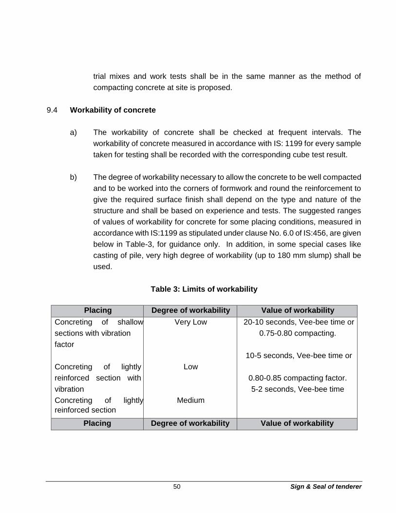
50 Sign & Seal of tenderer
trial mixes and work tests shall be in the same manner as the method of
compacting concrete at site is proposed.
9.4 Workability of concrete
a) The workability of concrete shall be checked at frequent intervals. The
workability of concrete measured in accordance with IS: 1199 for every sample
taken for testing shall be recorded with the corresponding cube test result.
b) The degree of workability necessary to allow the concrete to be well compacted
and to be worked into the corners of formwork and round the reinforcement to
give the required surface finish shall depend on the type and nature of the
structure and shall be based on experience and tests. The suggested ranges
of values of workability for concrete for some placing conditions, measured in
accordance with IS:1199 as stipulated under clause No. 6.0 of IS:456, are given
below in Table-3, for guidance only. In addition, in some special cases like
casting of pile, very high degree of workability (up to 180 mm slump) shall be
used.
Table 3: Limits of workability
Placing Degree of workability Value of workability
Concreting of shallow
sections with vibration
factor
Concreting of lightly
reinforced section with
vibration
Concreting of lightly
reinforced section
Very Low
Low
Medium
20-10 seconds, Vee-bee time or
0.75-0.80 compacting.
10-5 seconds, Vee-bee time or
0.80-0.85 compacting factor.
5-2 seconds, Vee-bee time
Placing Degree of workability Value of workability

51 Sign & Seal of tenderer
without vibration, or
heavily reinforced
sections with vibration
Concreting of heavily
reinforced sections
without vibration
High
or
0.85-0.92 compacting factor
or
25-75mm, slump for 20 mm
aggregate (for smaller aggregate
the values will be lower).
Above 0.92 compacting factor
or
75-125 mm slump for 20 mm
aggregate (for smaller aggregate
the values will be lower)
Note: Notwithstanding the values given above, the slump to be maintained for work in
progress shall be as per directions of the Engineer.
9.5 Mixing of concrete
a) Concrete shall be mixed in a mechanical mixer conforming to IS: 1791.
However, mixing shall preferably be done at a single central batching plant,
conforming to IS: 4925, situated within the area allocated for the Contractor’s
particular use as shown on the drawing or as directed by the Engineer. The
plant shall have a mechanically operated mixer of an approved size and type,
capable of ensuring a uniform distribution of the materials throughout the mass
and the mass is uniform in colour and consistency.
b) Water shall not be added into the drum of the mixer, until all the cement and
aggregates constituting the batch are already in the drum and dry mixed for at
least one minute and are uniformly distributed. Water shall then be added and
mixing of each batch shall be continued until there is a uniform distribution of
the materials and the mass but in no case shall mixing be done for less than
two minutes and for atleast 40 revolutions after all the water and materials are
in the drum. When absorbent aggregates are used or when the mix is very dry,
the mixing time shall be extended as directed by the Engineer. Mixers
shall not be loaded above their rated capacity as this prevents thorough mixing.

52 Sign & Seal of tenderer
c) The entire contents of the drum shall be discharged before the ingredients for
the next batch are fed into the drum. No partly set or remixed or excessively
wet concrete shall be used and it shall be immediately removed from site. Each
time if the work stops for more than 30 minutes, the mixer shall be thoroughly
cleaned and when the next mixing commences, the first batch shall have 10%
additional cement.
d) In exceptional circumstances and/or work in remote areas, hand mixing may
be allowed by the Engineer, subject to adding 10% extra cement which shall
be considered for reconciliation purposes. The mixing shall be carried out on
watertight platform and mixing shall be continued till a uniform colour and
consistency of the mix is achieved.
9.6 Concrete conveying
a) Concrete shall be handled and conveyed as rapidly as practicable, from the
place of mixing to the place of final laying, by approved means, before the initial
setting of the cement starts. Concrete shall be conveyed in such a way that
there is no segregation or loss of any of the ingredients and maintaining the
required workability. If segregation does occur during transport, the concrete
shall be remixed.
During very hot or cold weather, if directed by the Engineer, concrete shall be
transported in deep containers which will reduce the rate of water loss by
evaporation in hot weather and heat loss in cold weather, at no extra cost to
the Owner.
b) Conveying equipment for concrete shall be mortar tight, well maintained and
thoroughly cleaned before commencement of concrete mixing. Such
equipment shall be kept free from set concrete. Chutes shall not be used for
transport of concrete without the written permission of the Engineer. The chute
in case permitted to be used shall be of such size and design as to ensure
practically continuous flow. Slope of the chute shall be so adjusted that the
concrete flow without the use of an excessive quantity of water and without

53 Sign & Seal of tenderer
segregation of its ingredients. The delivery end of the chute shall be as close
as possible to the point of deposit.
c) Concrete may be conveyed and places by mechanically operated equipment,
e.g. pumps or pneumatic placers only with the written permission of the
Engineer, who shall also review the entire scheme for which comprehensive
details shall be furnished by the Contractor.
9.7 Concrete placing
a) Concrete shall be placed and compacted in its final position before the cement
reaches the initial set and normally concrete shall be compacted in its final
position within minutes of leaving the mixer.
b) Where direct placement is not possible, the Contractor shall provide suitable
arrangements such as chutes, tremie, elephant trunks, etc. to confine the
movement of concrete as directed by the Engineer. Concrete shall not be
dropped from a height or handled in a manner which may cause segregation.
c) If concrete is placed by pumping, the consistency shall be the minimum
necessary for such conveyance of concrete. Before commencement of regular
pumping, the pipeline shall be lubricated by cement mortar (1:2), and once
pumping commences, stoppages shall be avoided.
d) Concrete shall not be placed in foundations on soft areas or where there is
standing water or debris. Such soft areas shall be removed and filled with
1:4:8/1:3:6 nominal mix concrete, as directed by the Engineer.
For rock surfaces, it shall be ensured that the rock is not unsound. On sloping
rock faces, rough steps or benches shall be formed and concrete shall not be
placed on a sloping rock surface. Prior to pouring concrete, the rock surface
shall be cleaned with a high pressure water and air jet and kept wet for three
hours. Also, before placing concrete, water shall be removed from depressions,
the rock surface shall be dried and a 10mm thick cement sand mortar (1:6)
layer shall be placed and worked into all crevices, cracks, depression, etc.

54 Sign & Seal of tenderer
e) The placing of concrete shall be a continuous operation with no interruption in
excess of 30 minutes between the placing of continuous portions of concrete.
Concrete shall be placed in continuous horizontal layers of 150 mm or higher
thickness as directed by the Engineer and thoroughly compacted before
placing next layer. The thickness of each layer shall be such that it will be
deposited before the previous layer has stiffened. When placing concrete
through reinforcing steel, care shall be taken to prevent segregation of the
coarse aggregates.
f) Approval by the Engineer of any of the materials and/or work as required herein
shall not relieve the Contractor of his obligation to produce finished concrete in
accordance with the drawings and specifications. Slots, openings, holes,
pockets, etc. shall be provided in the concrete as directed by the Engineer.
g) Slabs, beams and similar members shall normally be poured in one operation.
In special circumstances, with the approval of the Engineer, these can be
poured in horizontal layers, but it must be ensured that the under layer is not
already hardened. Bleeding of under layer, if any, shall be effectively removed.
Molding, throating, drip course, etc. shall be poured as shown on the drawings
or as desired by the Engineer.
h) After the concrete has been placed, it shall be spaded and thoroughly
compacted by approved mechanical vibrators to a maximum subsidence
without segregation and thoroughly worked around reinforcement or other
embedded fixtures into the correct form and shape. Hand tamping in some
cases may be allowed subject to the approval of the Engineer. Care must be
taken to ensure that the inserts, fixtures, reinforcement and formwork are not
displaced or disturbed during placing of concrete.
i) Whenever vibration has to be applied externally, the design of formwork and
the disposition of vibrators shall receive special consideration to ensure
efficient compaction and to avoid surface blemishes. Surface vibrators and
form attached vibrator shall not be permitted under normal conditions. Their
use shall require written approval of the Engineer.

55 Sign & Seal of tenderer
j) Vibrators shall penetrate both the layer poured and the under layer to ensure
good bond homogeneity and to prevent the formation of cold joints. Immersion
vibrators shall not be allowed to come in contact with steel reinforcement after
start of initial set. Also, they shall not be allowed to come in contact with forms
or finished surfaces.
k) Immersion vibrators shall have a ‘no load’ frequency, amplitude and
acceleration as per IS: 2505 depending upon the size of the vibrator. Immersion
vibrators shall be operated by experienced men. These vibrators shall be
immersed not more than 450 mm apart and withdrawn when air bubbles cease
to come to the surface. Such vibrators shall in no case be used to push
concrete inside the forms and vibrators shall be withdrawn slowly.
l) No concrete shall be placed in wet weather or on a water covered surface. If
there have been any signs of washing of cement or sand, the concrete shall be
entirely removed immediately. Suitable precautions shall be taken in advance
to guard against possible rains before leaving the fresh concrete unattended.
m) Mass concrete shall be poured in lifts not exceeding 1.0 m in height unless
otherwise indicated on drawings or as directed by the Engineer. Horizontal lift
shall not be more than 150 cm in thickness, according to provision of IS:457.
n) Formwork and reinforcement shall be approved in writing by the Engineer
before concrete is placed. Concrete shall be placed only after all preparations
for casting have been approved by the Engineer and approval given to proceed
with the casting in writing on pour card to be maintained by
the Contractor for this purpose and to be submitted alongwith the Contractor’s
bills.
o) Concrete, when deposited, shall have a temperature of not less than 5 degrees
Centigrade and not more than 40 degree Centigrade. When depositing
concrete in very hot weather, precautions shall be taken so that the
temperature of wet concrete does not exceed 40 degrees Centigrade while
placing. This shall be achieved by stacking aggregates under the shade and

56 Sign & Seal of tenderer
keeping them moist, starting curing before concrete dries out, etc. However,
before mixing / placing concrete, when the above temperature conditions vary
on either side, approval of the Engineer shall be obtained for the method of
execution.
9.8 Protection and curing of concrete
a) Newly place concrete shall be protected by approved means from rain, sun and
wind. Concrete placed below ground level, shall be protected from falling earth,
during and after placing. Concrete placed in ground containing any deleterious
substances, shall be kept free from contact with such ground or with water
draining from such ground, during placing of concrete and for a period of atleast
three days or as otherwise instructed by the Engineer.
b) The ground water around newly poured concrete shall be kept down to an
approved level by pumping or other approved means of drainage. Adequate
steps shall be taken to prevent floatation or flooding. Steps, as approved by
the Engineer, shall be taken to protect immature concrete from damage by
debris, excessive loading, vibration, abrasion, mixing with earth or other
deleterious materials, etc. that may impair the strength and durability of the
concrete.
c) As soon as the concrete had hardened sufficiently for the surface not to be
marked, it shall be kept in a damp or wet condition by pounding or by covering
with a layer of sacking, canvas, hessian or similar materials and kept
continuously wet for atleast seven days after final setting. This period may be
extended, at the discretion of the Engineer, upto fourteen days. Curing of
horizontal surfaces exposed to drying winds shall begin immediately after the
concrete has hardened. Concrete slabs and floors shall be cured for the
periods mentioned above by flooding with water of minimum 25mm depth.
d) Approved curing compounds may be used in lieu of moist curing with the
permission of the Engineer. However, such permission may be granted only in
specific cases. Such compounds shall be applied to all exposed surfaces of the
concrete, as soon as possible after the concrete has set.

57 Sign & Seal of tenderer
e) Quantity of water applied shall be such as to prevent erosion of freshly placed
concrete.
9.9 Construction joints
a) When work has to be interrupted, the concrete shall be rebated and/or keyed
at the joint to such shape and size as may be required by the Engineer or as
shown on the drawings. All vertical construction joints shall be made with stop
boards, which are rigidly fixed and slotted to allow for the passage of the
reinforcing steel. In the case of water retaining structures, basements, tunnels,
etc. water stop of approved material shall be provided, if so specified on the
drawings or as directed by the Engineer.
b) Construction joints shall be located as shown or described on the drawings.
Where it is not described, the joints shall be in accordance with the following
guidelines.
i) In a column, the joints shall be formed about 75 mm below the lowest soffit
of the beams framing into it, including haunches, if any. In flat slab
construction, the joint shall be 75 mm below the soffit of the column capital.
ii) Concrete in a beam shall be placed throughout without a joint. If
unavoidable, the joint shall be vertical and within the middle-third of the
span. When a beam intersects a girder, the joints in the girder shall be given
an offset equal to a distance twice the width of the beam and additional
reinforcement provided for shear. The joints shall be vertical throughout the
full thickness of the concrete member with suitable shear key wherever
shown on the drawing.
iii) A joint in a suspended floor slab shall be vertical at one quarter points of
the span and at right angle of the principal reinforcement.
iv) Construction joints in equipment foundations shall not be provided without
specific concurrence of the Engineer.

58 Sign & Seal of tenderer
v) Vertical construction joints in water retaining structures shall not be
permitted unless shown on the drawings.
However, if the Contractor desires any adjustments in the location of construction
joints (to suit site conditions) from those shown on drawings or from those explained
above, he shall obtain prior approval from the Engineer.
c) Before fresh concrete is placed, the cement skin of the partially hardened
concrete which was poured earlier shall be thoroughly removed and the surface
made rough and aggregate exposed, by wire brushing, hacking, water jetting,
air jetting or any other method as directed by the Engineer. The rough surface
shall be thoroughly wetted for about 1/2 hour and shall be dried and coated
with 10 to 15 mm thick layer of 1:1 freshly mixed cement and sand slurry.
Special care shall be taken to see that the first layer of concrete placed after a
construction joint is thoroughly rammed against the existing layer.
d) In forming a joint, concrete shall not be allowed to slope away to a thin edge.
The locations of construction joints shall be planned by the contractor well in
advance of pouring and they will have to be approved by the Engineer. The
Contractor’s proposals shall include atleast the location of construction joints,
the sequence of pouring, formwork details and their stripping times.
e) Where the concrete has not fully hardened, all laitance shall be removed by
scrubbing the wet surface with wire or bristle brushes. Care being taken to
avoid dislodgement of particles of aggregates. The surface shall be thoroughly
wetted and all free water removed. The surface shall then be coated with neat
cement slurry. On this surface, a layer of concrete not exceeding 150 mm in
thickness shall first be placed shall be well rammed against old work, particular
attention being to corners and close spots. Work thereafter, shall proceed in
the normal way.
f) For multiple lift work a suitable gap shall be maintained between setting of the
earlier placed concrete and the commencement of concrete pour. After
depositing concrete in columns, piers or walked time gap of minimum 4 hours,
59 Sign & Seal of tenderer
preferably 24 hours shall be maintained before depositing concrete in beams,
girders or slabs, supported there in order to avoid cracking due to settlement.
9.10 Work in extreme weather conditions
During hot weather (atmospheric temperature above 40 degree centigrade) of cold
weather (atmospheric temp at 5 degree centigrade and below) the concreting shall be
done as per the procedures and precautions set out in IS:7868 (Parts I and II).
9.11 Cleaning and finishing of concrete
a) All concrete surfaces shall have an even and clean finish free from
honeycombs, air bubbles, fins or other blemishes unmarred, reasonable
smooth. The formwork joint marks on concrete work exposed to view shall be
rubbed with carborandum stone and defects patched up with paste of cement
sand mortar (1:2) and cured. The finish shall be made to the satisfaction of the
Engineer. Concrete surfaces to be subsequently plastered or where brick work
is to be built against them, shall be adequately hacked as soon as the form is
stripped off so that proper bond can develop.
b) Immediately after removal of forms, the concrete shall be inspected and
defective areas as pointed out by the Engineer shall be removed partially or
entirely as directed. Holes, left by form bolts, etc. shall be filled-up and made
good with cement sand mortar of approved mix. All superficial defects such as
honeycombing, rough patches, etc. shall be similarly made good. If the
defective area is at a vulnerable location, e.g. at the ends of beams & columns
etc. then it may be necessary to cut out the member completely or in part and
reconstruct as directed by the Engineer. If epoxies have to be used, the same
shall be subject to the approval of the Engineer. Poured concrete affected by
faulty formwork shall be removed totally and replaced. If so directed, the
Contractor shall have to resort to grouting / shotcreting.
c) A smooth finish shall be obtained with the use of forms having smooth and
even surfaces and edges. Panels and form linings shall be of uniform size and
be as large as practicable and installed with closed joints. Upon removal of

60 Sign & Seal of tenderer
forms, the joint marks shall be smoothened off and all blemishes, projections
etc. removed leaving the surfaces reasonably smooth and unmarred.
d) Where integral cement concrete finish is called for, the surface shall be
compacted and then floated and treated with a straight edge and any high and
low spots eliminated. The work shall be carried out as per IS:2571
10. Sampling, testing and quality assurance including construction tolerances
10.1 General
a) Concrete cubes for works tests shall be cured under laboratory conditions,
except when in the opinion of the Engineer, extreme weather conditions prevail
at which time, these may require curing under job conditions.
b) For the purposes of statistical analysis, any substandard cube result, which in
the opinion of the Engineer, is due to improper sampling, molding or testing
shall be discarded and a dummy result shall be substituted. The value of a
dummy result shall be equivalent to the average value of the cubes from the
same grade of concrete tested immediately before and after the discarded
result. The number of such substandard cubes shall not exceed 5%.
c) If the ‘strength’ of the laboratory controlled cubes, for any portion of the
concrete work, falls below the compressive strength specified, the Engineer
shall have the right to order a change in the proportions or the water content
for the remaining portion of the surface.
d) If the ‘strength’ of the works cured test cubes falls below the specified strength,
the Engineer shall have the right to require provisions for temperature and
moisture control during the period of curing as necessary to secure the required
strength, and may require retest in accordance with the standard method of
securing, preparing and testing specimens from hardened concrete for
compressive and flexural strengths, or load tests to be made on the portion of
the building so affected. All such tests shall be made at the Contractor’s
expense.

61 Sign & Seal of tenderer
e) Unacceptable concrete work shall be dismantled by the Contractor and
replaced by fresh work, meeting the specification requirements. In the course
of dismantling, if any damage is done to the embedded items or adjacent
structures, the same shall be made good, by the Contractor, to the satisfaction
of the Engineer, at no extra cost to the Owner.
f) Only as a very special case and that too in non-critical areas, the Engineer may
accept concrete work which is marginally unacceptable as per the criteria laid
down in IS: 456. For such accepted work, payment shall be made at a reduced
rate prorate to the concrete cube strength obtained, against that stipulated.
g) Before placing concrete, the inside of forms shall be checked to ensure that
they are clean and thoroughly wetted or adequately treated. So as to prevent
absorption of water from the concrete.
h) Ultrasonic tests on the foundations of major equipment to ascertain the quality
and grade of concreting shall be carried out. The Owner shall arrange for the
specialized agency for conducting the test at his cost. The Contractor shall
provide all the necessary facilities and arrangement for conducting the test at
site in terms of access, scaffolding etc. In case of any defects, the Contractor
shall rectify the same as directed by the Engineer.
i) Rebound hammer test shall be carried out for ascertaining the quality of
concrete work, as directed by the Engineer.
j) Test shall be conducted for the water tightness of the liquid retaining structures
as per IS: 3370 and IS: 6494. The details and sequence of tests shall be as
given hereunder:
i) All arrangements, including supply of water for testing purposes, shall
be kept ready when the tank is nearing completion.
ii) Water supply to the tank shall be in stages of 300 to 450 mm height in
order to check the water tightness of the tank and location of leakage of
various levels.

62 Sign & Seal of tenderer
iii) The permissible drop in level in 24 hours shall be 6 mm in case of
covered reservoir/tank and 12 mm in the case of open reservoir/tank.
iv) The leakage points shall be marked and separately treated after
dewatering.
v) The reservoir/tank shall be retested for water tightness after rectification.
For basement type structures like cable vault, track-hopper, tunnel, neutralizing pit,
etc. the Contractor shall examine the water tightness against ingress of sub-soil
water.
Frequency of sampling and testing including the methods of conducting the tests
shall be as given in Annexure A.
10.2 Sampling of concrete
Samples from fresh concrete shall be taken according to IS:1199 and tested as per
IS:516.
a) Normally only compressive test shall be performed but the Engineer may
require other tests to be performed in accordance with IS:516.
b) i) Trial Mixes:
At least four trial mixes shall be made with; min. 6 test cubes for each
mix.
ii) Works Tests:
The min. frequency of sampling of concrete of each grade shall be according
to clause 14.2.2 of IS: 456-1978. However, after getting continuous
satisfactory results and in the case of voluminous concrete works, the
Engineer, may at his discretion reduce the frequency of sampling as
follows.
For each grade of concrete, and for each 8 hours (shift) of work or part thereof,
atleast one sample consisting of six specimens shall be taken from each
150 cum. of concrete or part thereof, 3 specimens shall be tested at 7
days and remaining 3 shall be tested at 28 days. However, in all cases,

63 Sign & Seal of tenderer
the 28 days compressive strength shall alone be the criterion for
acceptance or rejection.
c) To control the consistency of concrete from every mixing, slump tests and
compaction factor tests in accordance with IS:1199 shall be carried out by the
Contractor every two hours or as directed by the Engineer. Slumps
corresponding to the test specimens shall be recorded for reference.
d) The strength of sample shall be the average of the strength of three specimens.
The individual variation should not be more than ±15% of the average.
10.3 Unless otherwise specified, the tolerance in construction shall be as follows:
----------------------------------------------------------------------------------------------------------------
Description of Item/ Permissible
Structural element Deviation in mm
----------------------------------------------------------------------------------------------------------------
The dimensions of concrete as cast when compared with those on the drawings shall be
within the tolerance given below:
Faces of concrete in + 25 - 10
foundations and structural members against which backfill is
placed. --------------------------------------------------------------------------------------
--------------------------
Description of Item/ Permissible
Structural element Deviation in mm
----------------------------------------------------------------------------------------------------------------
Location of footing
(for RCC framed structures
only).
+ 25 - 25
Eccentricity of footing 2% of footing width of direction of
Top surface of slabs and of
Concrete to receive base plates
Misplacement but limiting to 50mm.

64 Sign & Seal of tenderer
to be grouted.
Alignment of beams, lintels,
columns, walls, slabs and
+ 5 - 5
similar structural elements.
Deviation from specified
dimensions of cross-sections
+ 5 - 5
of columns and beams.
Alignment of holding down
+ 12 - 6
bolts without sleeves.
Alignment of holding down
+ 1.5 - 1.5
bolts with sleeves.
Level of holding down
+ 5 - 5
bolt assemblies.
Embedded parts (in any
+ 10 - 10
direction). + 5 - 5
----------------------------------------------------------------------------------------------------------------
Description of Item/ Permissible
Structural element Deviation in mm
----------------------------------------------------------------------------------------------------------------
Centres of packets or holes
with greatest lateral dimension
not exceeding 150 mm. + 10 - 10
Variation in steps:
Riser + 1.5 - 1.5
Tread + 3.0 - 3.0

65 Sign & Seal of tenderer
Plumb 3mm for every metre subject to a
maximum of 10mm.
-------------------------------------------------------------------------------------------------------------------------
10.4 Acceptance criteria
The acceptance criteria of concrete shall be in accordance with clause no.15 of IS: 456-
1978. However, in exceptional circumstances, the Engineer may, at his discretion,
accept a concrete of lower strength than that specified at reduced rates. The concrete
shall be deemed to comply with the strength requirements if:
a) Every sample has a test strength not less than the characteristic value or
b) The strength of one or more samples, though less than the characteristic value,
in each case is not less than the greater of :
i) The characteristic strength minus 1.35 times the Standard Deviation and
ii) 0.80 times the characteristic strength; average strength of all the samples, is not less
than the characteristic strength + [1.65 - 1.65/ square root of (No. of samples)] times
the standard deviation.
10.5 Load test
If any work is found unacceptable whereupon the Engineer requires its removal and
reconstruction, the Contractor may request that it should be load tested in accordance
with the provision of clause no. 16.50 of IS:456-1978 as given below:
a) The test load shall be 125 percent of the maximum superimposed load for
which the structure or element was designed. This load shall not be applied
earlier than 28 days after the effective hardening of concrete. This test load
shall be maintained for 24 hours and during the entire duration of the test,
struts, strong enough to take the whole superimposed, dead and other loads
shall be placed in position, leaving a small gap under the members.

66 Sign & Seal of tenderer
b) The maximum deflection shall be measured after the test load is in position for
24 hours. Thereafter, the test load shall be removed.
c) If 24 hours after the removal of the load, the structure does not show a recovery
of atleast 75 percent of the maximum deflection, registered as in (b) above, the
test shall be repeated after a lapse of 72 hours. The structure shall be
considered to have failed to pass the test if the recovery after the second test
is not atleast 80 percent of the maximum deflection during the second test.
d) If the maximum deflection in mm, shown during 24 hours under load, is less
than 40 l sq / D, where I is the effective span in metres and D is overall depth
of the section in mm, it is not necessary for the recovery to be measured and
the recovery position of the above mentioned clause 10.5 (c) will not apply.
Section 3 - Reinforcement
11. Scope
11.1 This section of the specification deals with reinforcement for all reinforced concrete
works and covers the requirement of materials, their properties, storage, handling,
furnishing of bar bending schedules and the cleaning, bending, binding and placing of
reinforcement with suitable cover blocks. This shall also include the supply of
reinforcement, wherever required.
12. General requirements

67 Sign & Seal of tenderer
12.1 The Contractor shall prepare and furnish to the Engineer, bar bending schedules for
all RCC works for his review and approval. No work shall commence without the
approval of bar bending schedule by the Engineer, in writing.
12.2 The Contractor shall have to obtain prior written approval from the Engineer, if he
desires any adjustments in diameter or spacing of reinforcement. However, the
Contractor shall modify the bar bending schedule, when a particular type and size of
reinforcement would not be available, with the approval of the Engineer.
13. Materials
13.1 All steel for reinforced concrete works shall be in accordance with Technical
Specification for Properties, Storage and Handling of common Building Materials,
(vide module C2) which shall be deemed to form the part of this Specification.
13.2 All bars shall be thoroughly cleaned before being fabricated. Pitted and defective bars
shall not be used.
14. Bending and placing
14.1 Bending
a) Reinforcing bars supplied bent or in coils, shall be straightened before these are
cut to size. Straightening of bars shall be done in cold and without damaging the
bars. This is to be considered as a part of reinforcement bending and fabrication
work.
b) Unless otherwise specified, reinforcing steel shall be bent in accordance with
procedure specified in IS: 2502 and/or as approved by the Engineer. Bends and
shapes shall comply strictly with the dimensions shown on the approved bar
bending schedules and they shall be rechecked by the Contractor before bending

68 Sign & Seal of tenderer
and he shall be entirely responsible for their correctness. Bars correctly bent,
shall only be used. Unless specified otherwise or directed by the Engineer, the
detailing of reinforcement shall be in accordance with IS: 5525 and SP: 34.
c) No reinforcement shall be bent, when in position in the work without approval of
the Engineer, whether or not it is partially embedded in concrete. Where the
reinforcement bars are bent aside, at construction taken to ensure that, at no
time, the radius of the bend is less than 4 times the bar diameters for plain mild
steel or 6 times the bar diameters for deformed bars. Care shall also be taken
while bending back bars, to ensure that the concrete around the bar is not
damaged.
d) Welding of bars to obtain continually shall not be allowed, particularly for cold
twisted bars, unless specifically approved by the Engineer. If welding is
approved, the work shall be carried out as per IS:2751 and IS:9417, according
to the best practice and as directed by the Engineer.
14.2 Placing in position
a) All reinforcement shall be accurately fixed and maintained in position as shown
on the drawings by such approved means as steel chairs, and/or concrete spacer
blocks as per IS:2502. Bars intended to be in contact at crossing points by two
numbers annealed steel wire of 0.9 mm to 1.6 mm size conforming to IS:280 in
such a manner that they do not slip over each at the time of fixing & concreting.
The tying of bars shall be in crisscross manner.
b) Binders shall tightly embrace the bars with which these are intended to be in
contact and shall be securely held. The vertical distance between successive
layers of bars shall be maintained by provision of spacer bars. These shall be so
spaced that the main bars do not sag perceptively between adjacent spacers.
Bundled bars shall be provided wherever shown on the drawing to facilitate
concreting. Location of laps and development lengths, shall be as indicated on
the drawings.

69 Sign & Seal of tenderer
c) The placing of reinforcement shall be completed well in advance of concrete
pouring. Just prior to concrete pouring, the reinforcement shall be checked by
the Engineer, for accuracy of placement and cleanliness. Necessary corrections,
as directed by the Engineer shall be carried out. Care shall be taken to ensure
that projecting ends of ties and other embedded metal do not encroach into the
concrete cover. Where concrete blocks are used for ensuring the cover and
positioning of reinforcement, these shall be made of mortar 1:2 (1 cement: 2
sand) by volume and cured for at least seven days. The sizes and locations of
the concrete blocks shall be approved by the Engineer. The 28 days crushing
strength of cover blocks shall be atleast equal to the specified strength of
concrete in which the blocks will be embedded.
d) Laps and anchorage length of reinforcing bars shall be in accordance with IS:
456, unless otherwise specified. If the bars in a lap are not of the same diameter,
the smaller diameter will guide the lap length. Laps shall be staggered as far as
practicable and as directed by the Engineer and not more than 50% of bars shall
be lapped at a particular section. Mechanical connections, for splicing
reinforcement bars in congested locations may be used by the Contractor, only
if approved by the Engineer. Reinforcement bars
shall not be lapped unless the length required exceeds the maximum available
lengths of bars at site.
15. Cover to reinforcement
a) Unless shown otherwise on the drawings, minimum clear concrete cover for
reinforcement (exclusive of plaster or other finishes) shall be as follows:-
o At each end of a reinforcing bar, not less than 25 mm, nor less than twice
the bar diameter.
o For a longitudinal reinforcing bar in a column, 40 mm or bar diameter
whichever is more. 25 mm cover may be adopted for columns of minimum
dimension 200 mm or under and with longitudinal reinforcement diameter
not exceeding 12 mm.
70 Sign & Seal of tenderer
o For longitudinal reinforcing bars in a beam, not less than 25 mm or less than
the bar diameter.
o For reinforcement in slabs and walls; not exposed to weather or ground not
less than 15 mm nor less than the bar diameter. o For bottom reinforcement
in footings: 75 mm, if concrete is laid against the ground or 40 mm if laid on
a layer of lean concrete.
o For retaining walls, grade beams, top and sides of footings and similar
surfaces exposed to weather or ground; 50 mm for bars larger than 16 mm
and 40 mm for bars upto 16 mm.
o For concrete members exposed to the action of harmful chemicals, acids,
alkalis, atmosphere, sulphurous smoke, sea water etc., the cover shall be
as shown on the drawings.
o For liquid retaining structures; 40 mm or diameter of main bars, whichever
is larger. This shall be increased to 50 mm in case of sea water or corrosive
environment.
b) Clean distance between reinforcing bars shall be in accordance with IS:456 or as
shown on drawings.
16. Sampling, testing and quality assurance
16.1 General
Sample bent bars shall be checked to ensure that they conform to the bar bending
schedules. Reinforcement in position shall be checked for proper positioning, and
rigidity, cover, spacing of bars, placement of chairs and spacers, etc. Also it shall be
checked that all bars at crossings are properly tied.
16.2 Tolerance

71 Sign & Seal of tenderer
Tolerance in construction, unless otherwise specified or as approved by the Engineer
shall be as follows:
----------------------------------------------------------------------------------------------------------------
Description of item/Structural Permissible Deviation
Element in mm (Max.)
----------------------------------------------------------------------------------------------------------------
Placing of reinforcement
For effective depth 200 mm or less +10 -5
For effective depth more than 200 mm +15 -10
Cover to reinforcement -5
Cutting of reinforcement
When minimum length specified +75 - When
maximum length specified - -50
When maximum or minimum length not
specified +75 -25
------------------------------------------------------------------------------------------------------------
16.3 Frequency of sampling and testing of reinforcement work shall be as given in Annexure
A.
Section 4 - Formwork and staging
17. Scope
This section of the specification deals with the requirements for the supply, erection,
dismantling of formwork and staging required for cast-in-situ concrete works including
for making pockets/block outs.
18. General conditions
The Contractor shall supply, fabricate, erect and dismantle (after use) all staging that
is required for all activities covered under the specifications. He shall prepare the
scheme and submit along with the supporting calculations for approval of the
Engineer.
72 Sign & Seal of tenderer
19. Materials
Formwork shall compose of steel, best quality wood or non-absorbent type plywood.
Timber shall be free from significant knots and shall be of medium grain as far as
possible and hard woods shall be used as caps and wedges under or over posts.
Timber shall be well seasoned, free from sap, shakes, worm holes, warps or other
surface defects and shall have smooth finish.
Staging, unless specified otherwise, shall generally be of mild steel tubes, steel beams
and channels etc. or strong sal ballies 150 mm in diameter or above. Bamboos, small
diameter ballies etc., shall not be used unless approved by the Engineer in specific
cases.
20. Classification of formwork
a) Ordinary
This shall be used in places where ordinary surface finish is required and shall
compose of steel and/or approved good quality seasoned wood.
Plywood shuttering can also be used by the Contractor.
b) Plywood
This shall be used in exposed surfaces as shown on drawings or as directed
by the Engineer where a specially good finish is required. Such surfaces shall
be formed using approved brand of heavy quality water resistant plywood to
produce a perfectly leveled, uniform and smooth surface. Reuse of such forms
may be permitted only after inspection and approval by the Engineer, for each
such reuse.
c) Formwork for shell roofs
For this item, the detailed design of formwork shall be submitted by the
Contractor to the Engineer, well in advance, for his approval. Units of shell

73 Sign & Seal of tenderer
forms may be used repeatedly but prior approval shall be required for each
repetition. Extra care shall be taken to keep correct levels and profiles.
21. Quality of formwork and staging
21.1 Formwork shall consist of all materials required for forming the boxing to pour
concrete, including steel/wood/plywood forms, ties, anchors, hangers, inserts, etc.
Formwork shall be so constructed that vertical and horizontal adjustments can be
made as required. The design and engineering of formwork including staging as well
as its erection and dismantling shall be the responsibility of the Contractor.
21.2 The staging shall be true and rigid and thoroughly braced in both directions as well as
cross braced, strutted and propped such that it will not deform unduly under weight of
concrete and other loads due to men, equipment, etc. Vertical member or props
should not be supported on an unpropped lower suspended floor or beam unless it is
ensured by the Contractor that the lower floor or beam can safely carry the loads. No
propping shall take place until the Engineer’s approval has been given to the
Contractor’s scheme submitted along with supporting calculations.
21.3 The forms and staging shall be sufficiently strong to carry without under deformation,
the dead weight of the concrete as liquid as well as anticipated working loads. Where
the concrete is vibrated, the formwork shall be strong enough to withstand the effects
of vibration, without appreciable deflection, bulging, distortion or loosening of its
components. The joints in the formwork shall be sufficiently tight to prevent any
leakage of mortar. The formwork shall be such as to ensure a smooth uniform surface
free from honeycombs, air bubbles, bulges, fins and other blemishes. Any blemish or
defect found on the surface of the concrete, must be brought to the notice of the
Engineer immediately and rectified as directed by him.
21.4 To achieve the desired rigidity, ample studs, braces, bolts, spacer blocks, wires,
clamps, ties, straps, shores, etc. Shall be used to hold the form in proper position
without undue distortion. These shall be approved by the Engineer but they must in
no way impair the strength of concrete or leave stains or marks on the finished surface.
Where there are chances of these fixtures being embedded, only mild steel or

74 Sign & Seal of tenderer
concrete of adequate strength shall be used. Bolts passing completely through liquid
and or earth retaining walls/slabs, basement walls etc. For the purpose of securing
and aligning the formwork, shall not be permitted.
21.5 For exposed interior and exterior concrete surfaces of beams and columns, plywood
or other approved forms thoroughly cleaned and tied together with approved corrosion
resistant devices shall be used. Rigid care shall be exercised ensuring that all column
forms are plumb and true and thoroughly cross braced to keep them so.
21.6 Beveled strips 25x25 mm shall be provided to form angles and in corners of columns
and beam boxes for chamfering of corners if shown on drawings or directed by the
Engineer. Temporary openings for cleaning, inspection and for pouring concrete shall
be provided at the base of vertical forms and at other places, where these are
necessary and as may be directed by the Engineer. The temporary openings shall be
so formed that they can be conveniently closed rigidly when required and must not
leave any mark on the concrete.
21.7 If it is so desired by the Engineer, the Contractor shall prepare, before commencement
of the actual work, designs and drawings for formwork and staging and get them
approved by the Engineer. Formwork shall be so designed and positioned that it can
be removed without damage to concrete.
21.8 The Contractor shall maintain necessary camber in centering for all floor slabs and
beams in all spanning directions, so as to offset the deflection and assume correct
shape. The camber shall have the crown of not less than 8 mm for every 5 metres
span unless otherwise shown on the drawings. For cantilever, camber at free end
shall be 1 in 100.
21.9 The Contractor shall provide the shuttering for complete stretch of work upto
expansion joints for the structures like shell, folded plate etc. and/or as directed by the
Engineer.
22. Cleaning and treatment of forms

75 Sign & Seal of tenderer
22.1 All forms shall be thoroughly cleaned of old concrete, wood shavings, saw dust, dirt
and dust sticking to them before these are fixed in position. All rubbish, loose concrete,
chippings, shavings, saw dust etc. shall be scrupulously removed from the interior of
the forms before concrete is poured. Wire brushes, brooms, compressed air jet and/or
water jet etc. shall be kept handy for cleaning, if directed by the Engineer.
22.2 Before formwork is placed in position, the form surfaces that will be in contact with
concrete shall be treated with approved non-staining oil or composition which is
insoluble in water and not injurious to concrete. Care shall be taken that the oil or
composition does not come in contact with reinforcing steel or stain the concrete
surfaces. Burnt oil shall not be allowed to be used specially where the concrete
surface will require finishing and/or plaster.
23. Removal of forms
23.1 The Contractor shall begin the removal of formwork only after the approval of the
Engineer. He shall place on record the dates on which the concrete is placed in
different parts of the work and the dates of the removal of formwork therefrom. This
record shall be checked and countersigned by the Engineer. The Contractor shall be
responsible for the safe removal of formwork but the Engineer may delay the time of
removal if he considers it necessary. Any work showing signs of damage through
premature removal of formwork, shall be entirely removed and reconstructed by the
Contractor at no extra cost to the Owner.
23.2 The formwork shall be so designed and erected that the forms for slabs and the sides
of beams, columns and walls may be removed first, leaving the beam bottoms and
their supports in position. Re-propping of beams shall not be done except with the
approval of the Engineer. Formwork for columns and walls at each stage of concreting
shall be erected only upto the particular lift of construction. Wedges, spacer bolts,
clamps or other suitable means shall be provided to allow accurate adjustment of the
formwork and to allow it to be removed gradually without jerking the concrete.
23.3 Forms of various types of structural components shall, under normal circumstances,
not be removed before the minimum periods specified in Cl. 10.3 of IS:456-1978,
which shall also be subject to the approval of the Engineer. However, in any case

76 Sign & Seal of tenderer
formwork shall not be struck until the concrete has reached strength, atleast twice that
of the stress to which the concrete may be subjected to at the time of removal of forms.
In normal circumstances and where ordinary Portland cement is used, forms may
generally be removed after the expiry of the following periods, according to clause no.
10.3 of IS:456-1978.
i. Walls, columns and vertical faces of all structural
members as directed by the Engineer.
1 to 2 days
ii. Slabs (Props left under) 3 days
iii. Beam soffits (props left under) 7 days
iv. Removal of props under slabs
Spanning up to 4.5 m 7 days
Spanning up to 4.5 m 14 days
v. Removal of props under beams
Spanning up to 6 m 14 days
Spanning over 6 m 21 days
vi. Cantilever slabs 14 days
23.4 The number of props left under, their sizes and disposition shall be such as to be able
to safely carry the full dead load of the slab, beam or arch as the case may be together
with any live load likely to occur during curing or further construction.
23.5 Where the shape of the element is such that the formwork has reentrant angles, the
formwork shall be removed as soon as possible after the concrete has set, to avoid
shrinkage cracking occurring due to the restraint imposed.
23.6 In case of cantilever slabs, the removal of forms shall begin from the outer edge and
proceed towards the support, where as in the case of slabs supported on two/four
sides, the removal of forms shall begin from centre to supports.
23.7 The formwork shall be so made as to produce a finished concrete, true to shape, lines,
plumb and to dimensions as shown on the drawings. The Engineer may call for

77 Sign & Seal of tenderer
finished work at any time to set standards of workmanship. Once approved, these will
become the accepted Sample.
23.8 In case PPC/PSC is used instead of OPC, the removal of shuttering/support shall be
after 50% more time from that being applied for OPC, unless otherwise permitted by
the Engineer. For concrete temperature above 40 °C, stripping time shall be
increased.
23.9 In case of special structures, such as shells, folded plates, etc., the sequence of
removal of forms shall be as per drawings or as directed by the Engineer.
24. Reuse of forms
Before reuse, all forms shall be thoroughly scraped, cleaned, all nails and adhering
substances removed, holes and leaks satisfactorily plugged, joints examined and
where necessary repaired and inside surfaces treated as specified herein before.
Formwork shall not be used/re-used, if declared unfit or unserviceable by the
Engineer.
25. Testing and quality assurance (including dimension tolerance)
25.1 General
Staging shall be checked for its soundness as a whole and for adequacy of the joints
and its foundations. All joints shall be either vertical or horizontal and shall be such
as to avoid loss of liquid through the formwork.
25.2 Dimensional tolerance for formwork
Levels and heights ± 6 mm
Plumb 3 mm for every metre subject to a maximum of
10mm.
Unevenness of any surfaces ± 3 mm
Length or breadth ± 12 mm
Diagonals ± 15 mm

78 Sign & Seal of tenderer
In case of inclined surfaces like track hopper wall, folded plates etc., the deviation
in the alignment of inclined surfaces, shall not exceed 3 mm with reference to the
theoretical alignment, for a length of 1000 mm measured vertically, subject to a
maximum of 10 mm.
In addition to above, requirement of clause no. 10.3 shall be complied with, which
shall be the final acceptance criteria of concrete work.
25.3 Frequency of sampling and testing of work, shall be as given in Annexure A
Section 5 - Embedded parts
26. Scope
This section of specification deals with the supply, fabrication (where called for) and/or
erection of embedded steel parts and PVC pipes
27. General requirements
27.1 Embedded steel parts shall be furnished by the Owner for transportation &
erection by the Contractor or supplied, fabricated and erected by the Contractor
as stipulated. If supplied by the Owner, these parts shall be furnished
anywhere within the project area and the Contractor shall transport the same
to the work site.
a) Embedded steel parts supplied, fabricated and erected by the Contractor shall
include items such as, but not limited to, foundation grillages, anchor bolts, pipe
sleeves, equipment mounting plates, steel pieces properly welded with
necessary lugs as shown on the drawings, auxiliary framing for equipment
supports, pesty plugs for door and window frames, dowel bars for concrete
work, miscellaneous frames, etc.
79 Sign & Seal of tenderer
b) Embedded steel parts supplied, fabricated/erected by the Contractor shall also
include items such as, but not limited to plate inserts, edge protection angles,
rolled sections with or without properly welded lugs.
c) Cold work deformed steel bars shall not be used for lugs.
28. Materials
The materials shall be in accordance with the relevant clauses of Technical
Specification for ‘Properties, Storage and Handling of Common Building Materials
(vide module C2), which shall be deemed to form a part of this specification. Mild steel
pipes shall conform to IS:1161. Unless otherwise specified, medium class pipes shall
be provided/ PVC pipes shall conform to IS:4985. Minimum pressure rating shall be 2
Kgf/cm2.
29. Fabrication, erection etc.
29.1 The Contractor shall fabricate, transport to site and erect accurately in position
all embedded steel parts either by welding, bolting or any other means as
approved by the Engineer. Exposed surfaces of embedded parts other than
holding down bolts, unless otherwise stated, are to be painted with two coats
of approved anticorrosive paint (as per IS:2074) and/or bituminous paint as
directed. The threads of holding down bolts shall be greased and protected
with waterproof tape.
29.2 During erection, the Contractor shall provide necessary strong temporary
bracings and supports to ensure proper installation of the embedded parts
which shall be erected at the true locations as shown on the drawings and these
shall be in plumb and level (unless otherwise shown on drawings). The
Contractor shall furnish the Engineer with fabrication and assembly drawings
prepared for embedded steel parts showing the erection procedure, for major
items, wherever necessary.

80 Sign & Seal of tenderer
29.3 Fabrication & erection shall be carried out as per IS:800. Welding rods & site
/field welding shall conform to IS:816 and IS:9595. IS:7634 (part-III) shall be
followed for PVC pipe works.
Section 6 - Foundation bolt assembly
30. Scope
This section of the specification deals with the requirements of supply, fabrication and
erection of foundation bolt assembly etc.
31. General requirements
Supply, fabrication, erection and installation of Foundation bolt assembly shall
comprise of foundations bolts, stiffener plates, washers, nuts, lock nuts, pipe sleeves
etc.
32. Materials
32.1 Foundation bolts shall generally conform to IS:5624. Mild steel bars used
for the fabrication of bolt assembly shall conform to grade-I of IS:432,
IS:226, IS:2062 or any other material including high carbon/high tensile
steel as specified.
32.2 Hexagonal nuts and lock nuts shall conform to IS:1363 & IS:1364 upto M
36 dia and IS:3138 and M 42 to M 150 dia.
32.3 Flat plain washers shall be of mild steel and punched/machined type
conforming to IS: 5369.
32.4 Steel pipe sleeves shall conform, to Medium class of IS:1161.
33. Fabrication, erection, etc.
33.1 The fabrication and erection of bolt assemblies shall include threading,
cutting, grinding, drilling, welding, etc., complete. All bolts, bolts
assemblies, etc. shall be fabricated by the Contractor to the correct
dimensions and shapes as shown on drawings, supplied by the Engineer.

82 Sign & Seal of tenderer
he bolts shall have coarse pitch screw thread in the diameter range, 8 to
64 and 6 mm pitch screw for diameter > 64 mm as per IS: 4218.
For fabrication of any particular size of bolt indicated on the drawing, the
diameter of the threaded portion of the bolt shall be considered as the
diameter of the bolt.
33.2 Every bolt shall be provided with steel washer, under the nut. The washer
shall be flat and min. outside circle have a diameter 2.50 times that of the
bolt and of suitable thickness. All nuts shall be of steel with well formed
hexagonal heads unless specified otherwise, forged from solid metal and
shall be dipped in hot boiled linseed oil as soon as these are made. The
nuts shall fit good on the bolts.
33.3 During erection, the Contractor shall provide necessary template,
temporary bracings, supports, etc. to ensure proper positioning of the
assemblies and holding them firmly until they are cast/grouted and the
grouted has set. All materials shall be erected in plump and in level
(unless otherwise specified) and at true locations as shown on the
drawings. Threads shall be protected by using PVC taps.
33.4 Fabrication & erection shall be carried out as per IS: 800. Welding shall
conform to IS: 816 and 9595.
Section 7 - Shotcreting
34. Scope
This section of the specification deals with the requirements of furnishing and
placement of shotcreting.
35. General requirements
35.1 Generally, shotcreting shall be done in accordance with IS:9012.
35.2 Reinforcement for shotcreting shall be as detailed below, unless
specified otherwise.
a) Reinforcement in one direction consisting of 6 mm M.S. bars at 750 mm c/c
shall be connected to the lugs of fastening of the wire fabric. This shall be used
in case of 50 mm or above thick shotcreting.
b) Wire fabric conforming to IS: 1566 shall be used as reinforcement and shall
consist of wire, 3 mm diameter, and spaced 50 mm both ways and shall be
electrically cross welded. Wire fabric shall be securely tied to 6 mm bars for
50 mm (min) thickness. Adjacent sheet of wire fabric shall be lapped at least
100 mm tied.
c) Clear cover to reinforcement mesh shall not be less than 15 mm.
35.3 This work shall be executed only by experienced operators, approved by
the Engineer.
35.4 Minimum thickness shotcreting shall be 50 mm. for abrasion resistant
and 25 mm for ordinary surface protection work.

84 Sign & Seal of tenderer
36. Materials
36.1 Generally, the materials shall be in accordance with the relevant clauses
of Technical Specification for properties. Storage and Handling of
common Building Material, which shall be deemed to form a part of this
Specification.
a) Fine aggregates shall consist of natural sand or crushed stone from a known
source and shall be strong, hard, coarse, sharp chemically inert, clean and free
from any coating. It shall be free from clay, coal or coal residue, organic or any
other impurities that may impair the strength or durability of the concrete and
shall conform to IS:383.
b) Fine aggregate (sand) shall be well graded and particles shall range in size
within the following limits. The Engineer, may approve the use of any other
grading as per the requirements of IS:9012.
IS sieve designation Percentage passing by weight
10 mm 100
4.75 mm 90 – 100
2.36 mm 60 – 95
1.18 mm 45 – 80
600 microns 35 – 60
300 microns 8 – 30
150 microns 0 – 10
c) The fineness modules shall be preferably between 2.5 & 3.3. Any other value
can be used, with prior approval of the Engineer.
36.2 Water shall be clean & free deleterious matter and shall have same
properties, stipulated for use in concrete work.

85 Sign & Seal of tenderer
36.3 Set accelerating and water proofing shotcreting admixtures of approved
make shall be used wherever required.
37. Application
37.1 After the placement of reinforcement and/or welded mesh and not more
than six hours prior to the application of shotcrete, the surface shall be
thoroughly cleaned of all loose material and dirt. The Contractor shall
properly prepare the surfaces, reinforcement and/or welded mesh to
receive the shotcrete. Cleaned surfaces shall be wetted not more than
one hour prior to shotcreting.
37.2 The mix as placed on surface shall one part cement to three parts
approved sand by volume. Cement and sand shall be dry mixed; no
water shall be added after mixing and before using in the gun. The
quantity of water when added, shall be only that which is sufficient to
hydrate the cement. For average atmospheric conditions, the water
cement ratio for shotcrete in place shall be between 0.35 and 0.5.
Suitable admixture shall be used wherever required.
37.3 A uniform pressure of not less than 2.5 Kgf/cm2 at the nozzle shall be
maintained. Necessary adjustments shall be made to ensure this
pressure, taking into account the length of hose and height of the place
to be shotcreted.
37.4 The application shall proceed in an upward direction. Beams, stiffener
and intermediate walls, if any, shall be wrapped with wire fabric and
completely covered with shotcreting. All rebound shall be removed from
the area of application as the work progresses and such rebound
material shall not be reused.
38. Curing

86 Sign & Seal of tenderer
As soon as the freshly shotcreted surface shows the first dry patches, a fine spray of
water shall be applied to keep it moist. After the surface has hardened, it shall be kept
continuously moist for minimum seven days. If there is extreme heat, especially when
accompanied by hot winds, the shotcreted surface, immediately upon completion,
shall be covered with burlap of similar covering, which must be kept continuously
moist for 14 days after shotcreting. The temperature of the lining shall not be permitted
to exceed 38 Degrees Centigrade during placing and curing.
Section 8 - Grouting
39. Scope
This section of the specification deals with the requirements of furnishing and
placement of grout in block outs and foundation bolt holes and underpinning of base
plates In case special type of grouting is required for the machine base plate, the
contractor shall submit the details of the same and get it approved from the Engineer.
40. General requirements
40.1 The space between the top surface of the foundation and the underside
of the base plate shall be filled with appropriate grout.
40.2 Crushing strength of grout shall be one grade higher than the foundation
concrete. Minimum crushing strength shall be 25N/sq.mm. Unless
otherwise specified.
40.3 The contact area between the grout and base plate shall not be less
than 80%.
41. Materials
41.1 Cement shall be Ordinary Portland Cement slag cement or Pozzolana
Portland Cement conforming to IS: 269, 455 and 1489 respectively.

87 Sign & Seal of tenderer
41.2 Sand shall be clean and well graded conforming to IS 383. For flow able
grout, sand conforming to zone-4 grade shall be used. Coarse
aggregate wherever used shall also conform to IS: 383.
41.3 Clean potable water as recommended for concrete mix shall be used.
41.4 Admixtures
a) Non-shrink admixtures of approved make shall be used.
b) Plasticizer conforming to IS:9103 shall be used to increase the workability,
wherever required.
42. Mixing and placing
42.1 Type of mix
There shall generally be following three types grout mix::
i) Ready mixed non-shrink cementations grout
ii) Cement-Sand Grout: The proportion of cement to sand shall generally be 1:2,
unless otherwise specified.
iii) Cement Aggregate Grout: The approximate proportions of cement, sand and
coarse aggregate shall be 1:1:25:2, with a maximum size of aggregate as 10
mm. This mix shall generally be used for grout thickness above 40 mm for dry
pack application.
42.2 Mixing
Depending upon the case of placement and method of application, there shall be
following three grout consistencies.
a) Fluid Mix

88 Sign & Seal of tenderer
Water-cement ratio shall be 0.6 (max.) may be added to increase workability,
wherever required. This grout mix shall be suitable for application with low
pressure grouting equipment or self flowing and suitable for grouting of
pockets/block outs, etc.
b) Plastic Mix
Water-Cement ratio shall be about 0.5. This grout mix shall be suitable for
application with trowel or rod.
c) Stiff Mix
Water-cement ratio shall generally be 0.4. This grout mix shall be suitable for
dry-pack application. The consistency should allow pressurizing into firm hard
ball without cracking.
42.3 Placing
The block outs, bolts holes etc. which have to be grouted, shall be cleaned thoroughly
by use of compressed air just prior to taking up the grouting operations.
42.4 Cement, sand, aggregate, and non-shrink admixture of approved quality
and proven make shall be first blended thoroughly in the required
proportion as per manufacturer’s specifications. Grout shall then be
prepared by mixing this admixture with water. Any grout which has been
mixed for a period longer than half an hour shall not be used on the
work.
42.5 Immediately after preparation, a grout of suitable mix shall be poured
into the block outs, pockets and bolt holes either from the sides or
through the holes provided for this purpose in the base plate, by using
special equipment for pressure grouting. It shall be ensured by Roding
and by tapping of bolts that the block out is completely filled without
leaving any voids. The pouring shall cease as soon as each hole is filled

89 Sign & Seal of tenderer
and any excess grout found on the surface of the concrete foundation
shall be completely removed and the surface dried.
42.6 The space between the top surface of the foundation concrete and the
underside of the base plate shall be filled with appropriate grout type.
Grouting, once commenced, shall be done continuously. Grout shall be
worked from one end to the other (to prevent air entrapment) and until
the grout oozes out through the grout holes provided in the base plates.
42.7 In case of stiff mix, the space between the top surface of foundation
concrete and the underside of the base plate shall be dry packed by
firmly pressing or ramming into place against fixed supports.
42.8 When it is clear that the centre of base has been properly filled, the grout
outside the base plate shall be briefly rammed to ensure compaction
below the edges. Shims provided for the alignment of plant bases shall
be positioned at the edges of the base to permit subsequent removal
which shall take place not less than 7 days after the grouting has been
executed. The resulting cavities shall be made good with the same
grade of grout as has been used for grouting under the rest of the base
plate.
42.9 Curing
The work shall be cured for a period of atleast 7 days commencing 24 hours after the
completion of the grouting. The curing shall be done by covering the surfaces with
wet gunny bags and flooding.

Section 9 - Encasement of steel structures / elements
43. Scope
This section of specification deals with the requirement for encasement of steel work
in concrete with necessary formwork, placing, finishing and curing, complete as per
drawings and specifications.
44. General requirements
44.1 All concrete work, reinforcement, formwork & staging work shall be done as per
stipulations of section 2, 3 and 4 of this specification.
44.2 The reinforcement to be provided for encasement of steel elements shall be mild
steel bars or in the form of wire netting. Such reinforcement shall be kept 20 mm
away from the steel member and held securely to it.
44.3 The minimum grade of concrete to be used for encasing shall be M-20 unless
specified. The aggregate to be used in concrete shall be 12.5 mm maximum size
unless specified otherwise. In case of box type steel sections, encasement shall be
done with cement, sand mortar (1:4) with thickness of 50mm over 0.9 mm size wire
netting conforming to IS:3150, or as shown on the drawings.
44.4 In the case of encasement of beams with concrete, if the gap between the edge of
the shuttering and flange is hardly sufficient for placing the concrete, the workability
of the concrete shall be increased suitably by increasing the water-cement ratio.
44.5 Minimum cover for concrete encasement shall be 50 mm
45. Materials
The materials shall be in accordance with the relevant clauses of Technical Specification for
Properties, Storage and handling of common Building Materials which shall be
deemed to form the part of this specification.
46. Wire netting
91 Sign & Seal of tenderer
Hexagonal wire netting shall be 0.9 mm dia and 19 mm aperture size, conforming to
IS:3150.
Section 10 - Joints in concrete
47. Scope
This section of the specification deals with the requirement of furnishing and installing
of joints including joint filler materials, water bars, resilient pads type vibration damping
material in an around the side of concrete works etc.
48. General requirements
Details of joints shall be as approved by Engineer or as per approved drawings. Where
necessary or / and specified, joints shall be made water tight by use of water stops.
49. Classification of joints
From the point of view of utility, the joints as provided may be classified as below:
a) Construction joints
Construction joints are produced by placing fresh concrete against surface of
hardened concrete. Construction joints are generally, but not necessarily,
vertical or horizontal. Requirements of construction joints shall be as per clause
specified elsewhere.
b) Contraction joints
These are provided to eliminate tensile stresses due to shrinkage and are commonly
used where temperature variations are small and where there is no likelihood
of expansion, such as spaces below water and earth levels and unexposed to
atmosphere. At contraction joints, the reinforcement is discontinued and bond
is not allowed to develop between the joint faces, thereby introducing a

92 Sign & Seal of tenderer
structural discontinuity. A contraction joint also serves as a construction joint
so far as break in the pouring of concrete is concerned.
c) Expansion joints
These are provided either to completely eliminate or to significantly reduce
comprehensive stresses in concrete that would otherwise result from thermal
expansion and might crush, buckle or crack part of the structure. Expansion
joints serve the purpose of contraction and also construction joints.
d) Control joints
At places where cracking is inevitable, places of weakness are introduced by the
provision of control joints so that the cracking takes place along these joints
instead of allowing it to develop in a haphazard manner.
e) Separation joints
The places where the expansion of the structure is not expected but they are required
to be kept structurally separate so that stresses, vibrations, etc. are not
transferred, a separation joint should be provided. Like expansion joint, a gap
is provided in separation joint also, but this is not expected to be used by the
expansion of members. In case, no gap is required, the separation joint can be
obtained by using an approved alkathene sheet stuck on the surface against
which concrete shall be placed.
f) Settlement joints
Structures, which are likely to settle with respect to the adjacent structures, shall be
separated by a settlement joint so that the adverse effects of differential
settlement are obviated. It is like an expansion joint but with a different sealing
arrangement.

93 Sign & Seal of tenderer
50. Materials
50.1 Joint filler
a) Bitumen board:
The bitumen impregnated fiber board; a preformed material shall be used as joint filler
which shall fill space between the concrete surfaces at the joints. The minimum
thickness of board shall be 12 mm and the material shall conform to IS: 1838.
b) Expanded polystyrene :
The expanded polystyrene slab shall be of fire retarding grade (type-2) conforming to
IS: 4671. Density of material shall not be less than 25 kg/cum.
50.2 Water stops
a) Water stops shall be provided at the joints as a continuous diaphragm to
contain the filler material and/or to exclude passage of water or any other
material into or out of the structure.
b) The water stops shall be either metallic like Copper, or non-metallic like P.V.C.
the material is to be procured from reputed manufacturers having proven
records of satisfactory supply of Water Stops of similar make and shape of
other jobs. Only PVC water stop shall be used, unless, otherwise, specifically
approved by the Engineer.
c) Non-metallic Water Stop :
These will be normally in PVC and can be of shape having any combination of the
following features: i) Plain ii) Central Bulb iii) Dumb-bell or flattened ends iv)
Ribbed and Corrugated Wings
v) V-shaped
vi) Kicker type (Externally placed)

94 Sign & Seal of tenderer
Water bars shall generally meet the stipulations of IS:12200. The minimum thickness
of PVC Water Stops shall be 5 mm and the minimum width 225 mm, unless otherwise
specified in the schedule of items. However, for some non-critical areas 150 mm wide
and 5 mm thick water stop can be used. The actual size and the shape will be as
shown on drawings and/or as directed by the Engineer. The material should be of
good quality Polyvinyl Chloride, highly resistant to tearing, abrasion and corrosion as
well as to chemicals likely to come in contact with during use. The performance
requirements shall generally be as follows:
Sp. Gr : 1.3 to 1.4
Shore hardness : 60A to 80A
Tensile strength : 116kgf / cm2 min.
Max. Safe continuous temp. : 70 degree C.
Ultimate elongation : Not less than 300%
Tear resistance : 45kgf / cm2 min.
Stiffness in flexure : 25kgf / cm2 min.
Accelerated extraction
i) Tensile strength : 110kgf / cm2
ii) Ultimate elongation : 250%
iii) Water absorption in 7 days : 5% (max.)
Effect of Alkali : 7 days
a) Weight increase : 0.25% max.
b) Weight decrease : 0.10% max.
c) Hardness change : + 5 %
Effect of Alkali : 28 days
a) Weight increase : 0.40% max.
b) Weight decrease : 0.30% max.
c) Dimension change : +1%
50.3 Sealing compound
a) Bitumen sealing compound:

95 Sign & Seal of tenderer
The bitumen sealing compound shall be from approved manufacturer and shall
conform to the requirements of IS: 1834. For joints in concrete lining on
canals/reservoirs, sealing compound conforming to IS: 5256 shall be used.
b) Polysulphide sealing compound:
This shall be two-part polysulphide sealant and shall be from approved
manufacturer, conforming to IS: 12118. Materials shall consist of polysulphide
polymer and a curing agent. Gun grade material shall be used unless
otherwise specified. The application of the sealant shall be strictly followed as
per manufacturer’s guidelines.
50.4 Metal cover strips
Metal cover strips shall be made from aluminium or mild steel sections as shown on
drawings. The min. thickness of aluminium strips shall be 3 mm and that of mild steel
6 mm. Aluminium alloy strip shall be corrosion resistant grade 31000 as per IS: 737.
Mild Steel shall conform to IS: 226 or IS: 2062.
50.5 Resilient pads
i) The vibration damping material shall be resilient rubber pads made up of natural or
synthetic rubber and shall have the following physical properties
a) Shore ‘A’ durometer hardness : 50 (+) / (-) 5
b) Min. elongation : 450%
c) Ultimate min. tensile strength : 145 kg/sq.cm
d) Rubber pads shall not absorb more than 10% of weight of water in a 7 days
test.
ii) The minimum thickness of the resilient pads shall be 12 mm.
51. Installation
51.1 Bitumen board / Expand polystyrene

96 Sign & Seal of tenderer
The bitumen impregnated fiber board may be secured to vertical concrete by nails in the first
placed concrete. The joint filler shall be coated on both faces with coal-tar pitch
conforming to IS: 216 or bitumen grade conforming to IS: 73 or IS: 702.
i) Water stops shall not have any longitudinal joints and shall be procured and
installed in largest practicable lengths having a minimum number of transverse
joints. The jointing procedure shall be as per the manufacturer’s
recommendations and shall be reviewed and approved by the Engineer. Suitable
field splicing kit including heater shall be used for this purpose. The edges shall
be neatly crimped and bent to ensure proper bond with the concrete.
ii) As Non-metallic Water Stops can be easily handled in very large lengths unlike
metal strips, transverse joints will be allowed only under unavoidable
circumstances and with the specific approval of the Engineer. The method of
forming these joints, laps etc. shall be as specified by the Manufacturer and/or
approved by the Engineer, taking particular care to match the centre and the
edges accurately.
iii) Particular care shall be taken for the correct positioning of the water stops to
prevent any faulty installation which may result in joint leakage.
Adequate provisions shall be made to support the water stops during the progress of
work and to ensure their proper embedment in the concrete. The symmetrical
halves of the water stops shall be equally divided between the concrete pours
adjacent to the joints.
Max. Density and imperviousness of the concrete shall be ensured by thoroughly
working in the vicinity of joints. However, particular care should be exercised
in use of vibrators in the proximity of joints to avoid dislodging of the water
stops.
iv) Splices
Splices in the continuity of intersections of runs of water stops shall be jointed as per
manufacturer’s stipulations depending on the type of water stops used. In case
of a cross section, overlapping must not be done but, instead factory made

97 Sign & Seal of tenderer
cross joint should be used. It is essential that the material is not damaged
during the splicing operation and that the continuity of the entire water stops
across the section be maintained.
v) Inspection
All water stops installations shall be subject to inspection and approval by the Engineer,
before concreting operations, encasing water stops, are performed.
51.2 Sealing compound
When directed, the gap in joints shall be thoroughly cleaned and sealing compound
laid as per manufacturer’s specification and approved drawings. Primer shall be
applied wherever required. For reservoir/canal lining, procedure as stipulated under
clause 9.0 of IS: 5256-1969 shall be followed.
51.3 Metal cover strips
The metal cover strips shall be pinned (using stainless steel) at one end and slotted at the
other end. Exposed surface of mild steel shall be painted with two coats of approved
anti-corrosive paint (as per IS: 2074) and/or bituminous paint. Welding of aluminium
shall be in accordance with IS: 2812.
52. Resilient pads:
The resilient pads shall be installed around the foundation or at other locations as shown on
the drawings. The pads shall be installed in position by sticking the same to the
foundations by using approved glue.
Section 11 - Waterproofing / damp proofing of underground concrete
structures
53. Scope
This section of specification deals with the retirements of all works for completing
waterproofing/damp proofing of underground concrete structure. This shall include
water retaining and basement type structures.

98 Sign & Seal of tenderer
54. General requirements
54.1 As a general guidance, the provisions of IS : 6494 shall be followed unless otherwise
mentioned.
The Contractor shall do the proper concreting so that concrete is water tight in itself
without any waterproofing treatment. The waterproofing treatment shall be provided
in exceptional cases, as additional precaution, as shown on the drawings or directed
by the Engineer.
54.2 The work of waterproofing / damp proofing of underground concrete structures by
course of bitumen felt, blown bitumen or any other operations shall be entrusted by
the Contractor to one of the well known expert agencies approved by the Engineer.
54.3 Actual type of waterproofing treatment to be provided for particular structure, shall
be as shown on the drawings or directed by the Engineer.
55. Bitumen felt treatment
55.1 Materials
a) The materials shall be in accordance with the relevant clauses of Technical
specification for properties, Storage and Handling of Common building
materials
b) The bitumen felt shall conform to IS: 1322 and the workmanship to IS: 1609
and IS: 3067. The bitumen felt shall be hessian based. Bitumen primer shall
conform to IS: 3384. The bonding materials shall consist of blown type bitumen
conforming to IS: 702 or residual bitumen conforming to IS: 73 or a mixture of
the two, to withstand local conditions of prevailing temperature gradient of
surface. The contractor shall satisfy the Engineer that the bonding materials
proposed to be used are suitable for the particular job.
55.2 Installation

99 Sign & Seal of tenderer
a) Waterproofing / Damp proofing for horizontal surfaces, unless specified otherwise
with two layers of felt on which subsequently concrete shall be placed, shall be
provided with the following treatments :
i) A minimum of 12mm thick plaster 1:4 (1 cement : 4 sand) with waterproofing
admixture / additives over PCC
ii) One coat of bitumen primer @ 0.4 kg/Sqm min.
iii) One layer of hot applied bitumen @ 1.5kg/sq.m. min.
iv) One layer of self finished felt (type - 3, grade II as per IS: 1322).
v) One layer of hot applied bitumen @ 1.5 kg/Sqm min.
vi) One layer of self finished felt (type - 3, grade - II as per IS: 1322).
vii) One layer of hot applied bitumen @ 1.5 kg/Sqm min.
viii) A minimum of 12mm thick plaster 1:4 (1 cement : 4 sand ).
b) Water proofing / Damp proofing for other surfaces (including vertical) unless
specified otherwise, with two layers of felt shall be provided with following
treatments:
i) One coat of bitumen primer @ 0.4 kg/Sqm min.
ii) One layer of hot applied bitumen @ 1.5 kg/Sqm min.
iii) One layer of self finished felt (type - 3, grade - II as per IS: 1322).
iv) One layer of hot applied bitumen @ 1.5 kg/Sqm min.
v) One layer of self finished felt (type - 3, grade II as per IS: 1322).
vi) One layer of hot applied bitumen @ 1.5 kg/Sqm min.

100 Sign & Seal of tenderer
vii) A minimum 25mm thick plaster 1:4 (1cement: 4 stand).
viii) Half brick masonry work in cement mortar 1:4 (1 cement: 4 sand) using
bricks of class designation 75, unless otherwise specified.
56. Miscellaneous treatment
56.1 Plastering treatment
After the side walls are constructed and allowed to undergo the specified curing, the
surface of the walls and the flooring should be made rough with a hacking tool, washed
clean with water and wire brushed so as to remove all the loose material, and a
waterproof cement plaster 1:3 mix, with suitable proportion of an integral
waterproofing compound shall be applied in two coats, the first coat being 12mm thick
and the next 10mm thick. The second coat shall be applied after allowing a time
interval of at least 24 hrs for the first coat to harden. Hexagonal galvanized netting of
0.90mm dia, 19 mm aperture size shall be used in the plastering. The netting shall
be fixed with the help of MS Screws, fixed with the help of fibrous plugs provided
before application of first layer of plaster.
56.2 Hot applied bitumen treatment
The external concrete of plastered surface shall be carefully cleaned, cured and
allowed to dry for some time before the application of a coat of hot bitumen of the
industrial grade 85/25 conforming to IS : 702 against ground water seepage. Rate of
application of bitumen shall not be less than 1.7 kg/Sqm and it should be heated to
about 120 C before application. Anti-stripping compound shall be added.
Antistripping and adhesion improving agent shall be 100% mixable in bitumen. The
stripping and adhesion improving agent shall be 100% mixable in bitumen. The
stripping value tested as per IS: 6241 should be nil when recommended quantity of
anti-stripping compound is mixed. Nominal mix proportion of the compound shall be
1 percent by weight of bitumen. However, actual mix proportion shall be as per
manufacturer's recommendation.

101 Sign & Seal of tenderer
56.3 Polymer modified cementitious coating treatment
a) Materials
i) Modified liquid polymer blend shall be a dispersion containing 100% acrylic
based polymer solids.
ii) Portland cement based dry powder
iii) Clean, fine specially prepared quartz sand approximately 0.6 mm size.
b) Mixing
The liquid polymer shall be stirred well and cement base powder shall then be
added slowly to make a slurry mix. For preparation of brush topping mix, quartz
sand shall be added slowly and mixed well till a homogenous mixture is
obtained. The mix shall be used within half an hour of the preparation. Addition
of quartz sand may not be necessary, in case dry power contains the same.
c) Properties of the coating
i) It must adhere to the wet surface
ii) It should develop adequate bond strength with the concrete surface, not
less than 2 N / Sqm
iii) Co-efficient of permeability shall be about 5 x 10 Cms
iv) Water absorption after continuous soaking shall not be more than 1%.
v) The materials shall be permeable under water vapor.
vi) The material shall be resistant to acids and alkalis’ present in the soil and
underground water with normal pH value between 4 and 14.

102 Sign & Seal of tenderer
vii) The co-efficient of thermal expansion of the material shall be close to that
of concrete.
d) Application
The concrete surface shall be cleaned and made free from grease, oils or loosely
adhered particles. The surface shall be damp without any free water.
i) For slurry mix: a minimum of 2 coats shall be applied on the surface. The
first coat being applied when the surface is still damp and left to harden for
4 to 6 hours. After 4 to 6 hours of the application of second coat, it shall be
finished by rubbing down with a soft dry sponge. The coverage shall not be
less than 1.1kg/sq.m in the 2 coats. A lap of 75mm shall be provided at the
joints.
The coating shall be air dried for 4 to 6 hours and, thereafter, cured for 7 days
after the application of last coat.
ii) For brush toping mix: This shall be applied in two coats. A primary coat of
slurry mix can also be first applied on the surface as first coat. After the
coating has dried up, a coat of brush toping mix shall be applied over it with
a push broom or any other similar brush. It shall be left in broom finished
condition. The nominal thickness shall be 1.5mm and minimum thickness
shall be 1.0mm. A lap of 75mm shall be provided at the joints. It shall be
ensured that no pinhole exists and re-brushing shall be done to cover the
pinholes if any.
The coating shall be air dried for 4 to 6 hours and thereafter cured for 7 days after
application of last coat.
57. Chemical injection treatment
Wherever shown on the drawing or directed by the Engineer, min 12mm dia (N.B.)
threaded nozzle of suitable length, shall be provided over the surface ad along the
construction joint line in a grid pattern at a spacing not exceeding 1.5m c/c before

103 Sign & Seal of tenderer
concreting operation. Adequate precaution shall be taken to keep the nozzles
plugged at both ends to prevent them from getting closed by concrete.
For fixing of any nozzle in set concrete suitable size hole shall be drilled, preferably
by using repercussive hammer drill electrically operated, in grid pattern and grouting
nozzle shall be fixed in these holes.
After the nozzles are fully set, neat cement slurry admixed with water soluble
nonshrink polymer/monomer based chemical shall be injected through the network of
nozzles with low pressure grout pumps at a pressure of about 2.0 kg/sq.cm. Water
cement ratio of the slurry shall not be more than 1:2. The resultant solution shall not
have viscosity greater than 1:2 centipoises. Plasticizing agent shall be added
wherever required. The grouting shall be started at very low pressure and increased
gradually to a required pressure. The grouting shall continue till the hole refuses to
take any further grout, even at an increased pressure. Applied pressure shall not be
more than the designed strength of the concrete. After completion of grouting
operation, the nozzles shall be sealed properly to the satisfaction of the Engineer.
Section 12 - Dismantling / demolishing work - RCC and PCC
58. Scope
This section of specification deals with the requirements of dismantling / demolishing
RCC and / or PCC work
59. General requirements
59.1 The dismantling implies, carefully taking up or down and removing without damage,
this shall consist of dismantling one or more parts of a structure. This includes chipping
work, making holes/ opening etc in concrete members according to the required
shape, size and profile at all elevations.
59.2 The term demolition implies, taking up or down or breaking up of a structure / member
in part or full as specified or shown on drawings or as directed by the Engineer

104 Sign & Seal of tenderer
59.3 In a structure / member, both dismantling and demolishing work may be involved. In
such case, the portion of work treated as demolishing shall be as shown on the
drawing or as decided by the Engineer
59.4 All materials obtained from the demolition/dismantling work shall be the property of
the owner, unless otherwise specified.
59.5 All serviceable materials obtained, shall be separated out and stacked properly upto
a lead of 500 metres or shall be returned to NTPC stores and all unserviceable
materials, rubbish etc shall be disposed off as directed by the Engineer upto a lead of
2 Kms.
59.6 The dismantling / demolishing operations shall be carried out in proper sequence so
that the serviceable material can be salvaged, without being damaged during the
process of work.
59.7 Necessary propping, shoring and under pinning shall be provided for the safety of the
adjoining work or property which is to be left intact, before dismantling / demolishing
work
60. Safety
60.1 All demolition work shall be carried out in conformity with the local safety regulations,
extreme caution being exercised to avoid damage to the work and the equipment,
which are to be left intact. Necessary precautions shall be taken to keep the dust
nuisance down. Safety requirements in IS: 4130 shall also be followed.
60.2 As and where necessary, the dismantled / demolished materials shall be lowered to
the ground and not thrown and then properly stacked as directed by the Engineer.
Wherever required, temporary enclosures shall be erected to minimize the dust or
moisture infiltration.

105 Sign & Seal of tenderer
Section 13 - Cement additives / admixtures in concrete
61. Scope
This section of specification deals with the requirements of furnishing, placing and
mixing cement additives / admixtures, in all kinds of cement concrete, (plain or
reinforced) for all kinds of structures at all levels.
62. General requirements
62.1 The Contractor shall furnish all labour and equipment to place and mix waterproofing
cement additive and cement plasticizer in concrete of any grade and cement mortar.
Thereafter he shall carry out the work as specified earlier in relevant clauses of this
specification for concrete and hence complete the work as indicated on the drawing
and as per the specification listed hereunder.
62.2 Waterproofing additive and other types of admixtures shall be as far as possible, free
from aggressive chemical like chloride, sulphide etc., which can cause corrosion of
steel reinforcement in RCC.
62.3 The Contractor shall have the services of the manufacturer's supervisor, at no extra
cost to the owner, to supervise the work, if directed by the Engineer.
62.4 Admixtures in concrete for promoting workability, improving strength, entraining air or
for similar purposes may be used only after the written permission from the Engineer,
is obtained. Addition to admixtures shall not reduce the specified strength or durability
of concrete in any case. The admixtures shall conform to IS: 9103 and shall be of
proven make and from a reputed manufacturer. Calcium chloride shall not be
permitted to be used other than in mass (plain) concrete works.
63. Materials
63.1 Waterproof cement additive shall conform to IS: 2645 and shall be of proven make
and from a reputed manufacturer.
63.2 Admixtures in concrete shall conform to IS : 9103 and shall be of proven make and
from a reputed manufacturer. In addition, for plasticizer cum waterproofing compound

106 Sign & Seal of tenderer
materials shall meet the permeability requirements as per IS: 2645. Similarly, for
plasticizer cum retarder admixture material shall satisfy the setting time requirements
of retarder and other properties of plasticizer as per IS: 9103.
64. Mixing
64.1 Admixtures / waterproofing additive shall be used at the rate specified by the
manufacturer or as indicated on the drawings and shall be mixed with water, as
required by the Engineer.
64.2 Samples of concrete in which admixture and / or waterproofing cement additive is
added shall be tested for water proofness, workability, compressive strength, water
absorption, density, setting time, etc., the results shall conform to relevant IS
specifications.
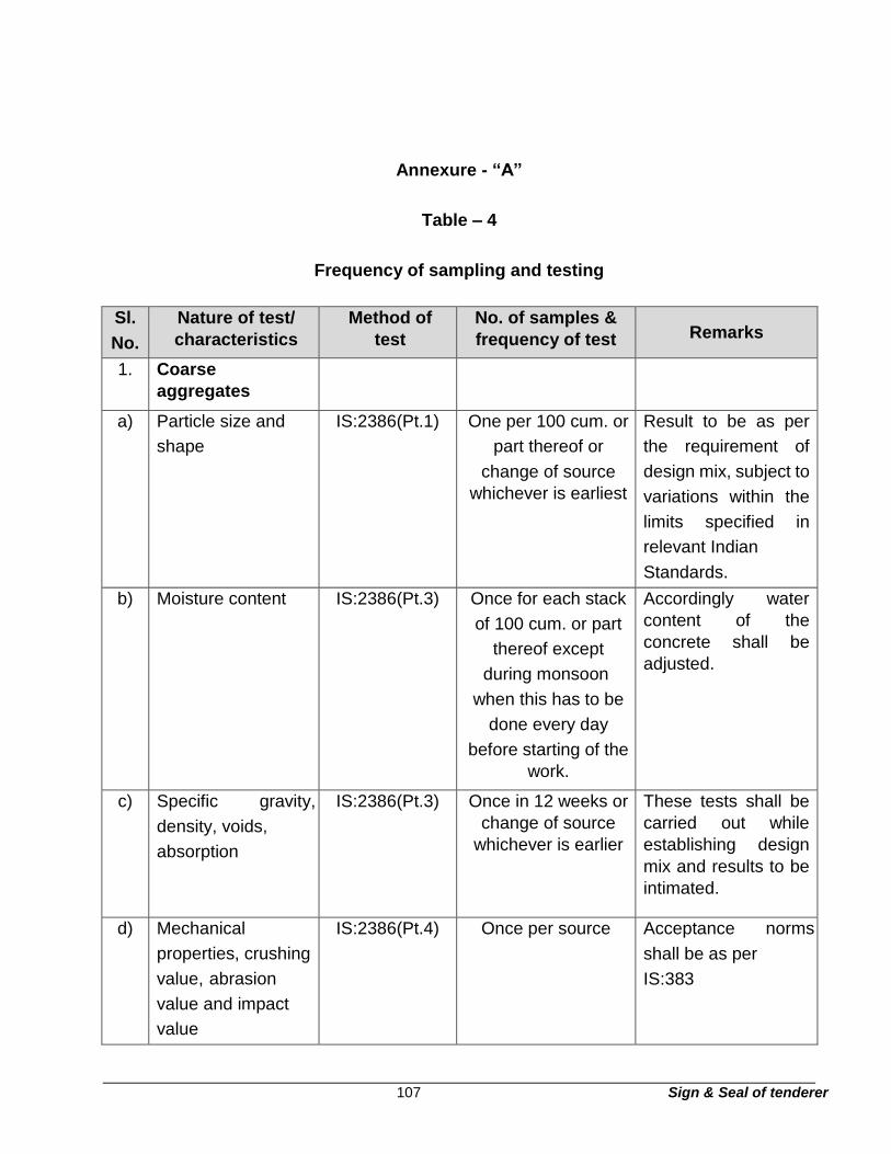
107 Sign & Seal of tenderer
Annexure - “A”
Table – 4
Frequency of sampling and testing
Sl.
No.
Nature of test/
characteristics
Method of
test
No. of samples &
frequency of test Remarks
1. Coarse
aggregates
a) Particle size and
shape
IS:2386(Pt.1) One per 100 cum. or
part thereof or
change of source
whichever is earliest
Result to be as per
the requirement of
design mix, subject to
variations within the
limits specified in
relevant Indian
Standards.
b) Moisture content IS:2386(Pt.3) Once for each stack
of 100 cum. or part
thereof except
during monsoon
when this has to be
done every day
before starting of the
work.
Accordingly water
content of the
concrete shall be
adjusted.
c) Specific gravity,
density, voids,
absorption
IS:2386(Pt.3) Once in 12 weeks or
change of source
whichever is earlier
These tests shall be
carried out while
establishing design
mix and results to be
intimated.
d) Mechanical
properties, crushing
value, abrasion
value and impact
value
IS:2386(Pt.4) Once per source Acceptance norms
shall be as per
IS:383

108 Sign & Seal of tenderer
Sl.
No.
Nature of test/
characteristics
Method of
test
No. of samples &
frequency of test Remarks
e) Soundness IS:2386 (Pt.5) Once per source Acceptance norms
shall be as per
IS:383.
f) Reaction with alkali IS:2386 (Pt.7) Once per source These tests shall be
carried out while
establishing design
mix and result to be
intimated.
Acceptance shall be
as per IS:2386 (Pt.7)
and Clause 7.4C of
this specification.
g) Flakiness and
petro-graphic
examinations
IS:2386 This is to be done
once and should be
repeated in case the
source is changed.
These tests shall be
carried out while
establishing design
mix and results to be
intimated.
h) Deleterious
materials
IS:2386 (Pt.2) Once per source Results should be
within the limit as
specified in relevant
Indian Standards and
in this
Specification.
2. Fine aggregates/
sand
a) Particle size and
shape.
IS:2386 (Pt.1) One per 100 cum. or
part thereof or
change of source,
whichever is earlier.
Should be as per the
requirement of
design mix, subject to
variation within the
limit as specified in
relevant IS Codes.

109 Sign & Seal of tenderer
Sl.
No.
Nature of test/
characteristics
Method of
test
No. of samples &
frequency of test Remarks
b) Specific gravity,
density, voids,
adsorption and
bulking.
IS:2386 (Pt.3) Once in 12 weeks or
change of source
whichever is earlier
These tests will be
carried out while
establishing design
mix and results to be
intimated.
c) Bulk age, moisture
content (Routine
test)
IS:2386 (Pt.3) To be done every
day before start of
work.
Volume of sand and
weight of water shall
be adjusted as per
bulk age and
moisture content.
d) Silt, clay
deleterious
materials,
organic
impurities.
IS:2386 (Pt.2) Once per source and
to be repeated, if
source is changed.
Volume of sand and
weight of water shall
be adjusted as per
bulk age and
moisture content.
e) Soundness and
Petrographic
examination.
IS:2386 (Pt. 5 &
8)
Once per source. Acceptance norms
shall be as per
IS:383.
f) Mortar
making
properties.
IS:2386 (Pt.6) -do- Acceptance norms
shall be as per
IS:383.
g) Reaction with
alkali.
IS:2386(Pt.7) Once per source Acceptance norms
shall be as per IS:383
and IS:2386
(Pt.7).
3. Cement
a) Setting time IS:4031 One sample of each
received from stores.
Acceptance norms
shall be as per
relevant Indian
Standard
b) Compressive
Strength
IS:4031 -do- -do-

110 Sign & Seal of tenderer
Sl.
No.
Nature of test/
characteristics
Method of test No. of samples &
frequency of test Remarks
4. Water
Harmful
substances, pH
value, initial setting
time, compressive
strength.
IS:3025,
IS:4031 &
IS:516
Once a month for
each source
Acceptance norms
shall be as per Cl.4.3
of IS:456-1978.
5. Concrete
a) Workability (Slump
and compaction
factor)
IS:1199 One sample every
two hours from every
mixing plant.
Acceptance value
shall be as per Cl.
6.1 of IS:456-1978.
b) Crushing Strength IS:516 i) As per Cl.14.2.2 of
IS:456-1978
for initial period ii)
One sample of six
cubes per 150 cum
or part
thereof for mass
concrete for
subsequent
period.
Acceptance criteria
shall be as per Cl.15
of IS:456-1978. A
minimum of 3 (Part7)
specimens shall be
tested for 28 days
strength.
c) Water-cement ratio IS:119 At random at the time
of batching
According to
mix design
d) Cement Content IS:1199 -do- -do-
e) Finished
dimensions
Physical
measurement
All structures Acceptance as per
Specification
6. Form work
a) Staging
(Durability
strength &
soundness of
staging, joints,
Visual Each member Any staging intended
for use shall be
approved by the
Engineer for its
durability and
strength

111 Sign & Seal of tenderer
Sl.
No.
Nature of test/
characteristics
Method of
test
No. of samples &
frequency of test Remarks
adequacy of its
foundation and
specific level)
After erection of
staging, nominated
representatives of
Engineer shall check
the soundness of the
staging as a whole,
its joints, adequacy of
its foundation and the
specific levels.
b) Shuttering
i) Materials Visual Random Formwork materials
shall be strictly as per
specifications and
approved of the
Engineer. Materials
for formwork shall be
unwrapped,
thoroughly clean and
without broken or
damaged edges
either due to
repetitive use or
otherwise. Oiling of
for m work before
concreting shall be
resorted to.
ii) Joints Visual Random Joints shall be leak
proof to avoid loss of
liquid
Sl.
No.
Nature of test/
characteristics
Method of
test
No. of samples &
frequency of test Remarks

112 Sign & Seal of tenderer
Section 14 - Slab on grade
65. Scope
This section of specification deals with carrying out the work of “slab on grade”. In all
medium duty industrial floors.
66. General requirements
66.1 The contractor shall furnish all material/ labour and equipment. The specifications
covered under section C-3, sub section 1 to 13 for cast in situ concrete and allied works
shall generally be applicable unless otherwise specified here under.
66.2 The work includes right from preparation of sub grade to completing and curing slab
on grade in all respects to the satisfaction of the Engineer.
67. Materials
(a) Materials for filling shall be crushed stone dust, sand or other inorganic materials
and they shall be clean and free from shingle, salts, organic matters, roots and
iii) Dimensions
and plumb
Physical
measurement
Each member and
before every lift.
Tolerance as per
Specification
7 Reinforcement
a) Placement Visual each The bar bending
schedule with the
necessary hooks,
laps, covers, spacers
and chairs shall be
100% checked for all
concreting works
before start of the
work.
b) Cutting tolerance Physical
measurement
Random Tolerance shall be as
per specification.
113 Sign & Seal of tenderer
excessive amount of sod, concrete or any other foreign substances which could
harm or impair the strength of the substructure in any manner.
(b) Stones for Granular sub base shall be broken stones to gauge not exceeding 63
mm and shall be free from dust, organic matters etc.
(c) Maximum size of 40 mm stone aggregate shall be used for concrete.
(d) Cement shall be ordinary Portland cement conforming to IS:269,Grade 43
(e) Admixtures in concrete for improving workability, strength etc may be used only
after the written permission from the Engineer.
(f) Water shall be clean, free from injurious matters. Potable water is generally
considered satisfactory.
(g) Reinforcing steel bars shall conform to grade 1 of IS:432 (part 1)
(h) Polysulphide sealant shall conform to IS 12118 Gun Grade.
(i) Concrete curing compound shall be CONCURE WB of M/s. Fosroc
Chemicals (India) Ltd., or equivalent.
68. Laying of slab on grade
i) Uneven (but fairly level) sub grade shall be dressed, leveled by necessary
Excavation / Scraping / Filling, watered, rolled by 10T roller and consolidated to
desired level.
ii) On consolidated sub grade, two layers of granular sub base each of 75 mm
thickness shall be laid Total consolidated thickness of sub base shall be 150
mm. Refer specification No.C-1.6.0 - Granular Sub Base (Hard core)
iii) On consolidated sub base water proof paper shall be placed with minimum
150mm overlaps on all sides.

114 Sign & Seal of tenderer
iv) Concrete grade M20, 150 mm thick shall be poured in strips as per drawing and
as directed by the Engineer.
The strips shall be prepared by placing formwork in straight line and level. Each strip may
be of size 4 metre wide x 20 metre long alternate strips shall be cast by leaving
24 hours interval in between.
Form work shall be strong enough to hold the screed vibrator.
The concrete shall be vibrated by screed vibrator / surface vibrator and when it becomes
touch dry it shall be machine trowel led to smooth uniform level surface. Ramp
surfaces shall then be “Broom Finished”.
Under no circumstances dry cement or cement slurry shall be separately spread
on concrete at any time.
Special care shall be taken to pour and vibrate the concrete along the form work
to avoid any segregation of aggregate and honey combing.
v) 24 hours after concreting, the form work shall be removed and immediately the
grooves of size 10mm x 50mm as shown on the drawing shall be cut in concrete
at an interval of about 4.0 metres or as shown on the drawing.
The grooves shall be cleaned and concrete surface shall then be sprayed by water based
concrete curing compound as specified. The grooves shall be filled up by poly
sulphide sealant after fourteen days.
vi) Dowels shall be provided along transverse and longitudinal construction joints as
shown on the drawing.
vii) Any expansion / contraction joints in slab on grade shall be provided at locations
and as per the details indicated on the drawing.
69. Acceptance criteria
All finished surface shall be smooth, uniform and at desired line and level within a
tolerance of ± 3.0 mm. It shall be free from cracks and warping.

115 Sign & Seal of tenderer
Section - T4
Technical specifications for masonry and allied works
1 Scope
This section of the specification covers furnishing, installation including handling,
transportation, batching, mixing, laying, scaffolding, centering, shuttering, finishing,
curing, protection and repairing till handing over of brick masonry and allied works
including DPC, plinth protection and dismantling.
2 General requirements
2.1 The Contractor shall furnish all skilled and unskilled labour, plant, equipment,
scaffolding, materials, etc. required for complete execution of the work in accordance
with the drawings and as described herein and/or as directed by the Engineer.
2.2 All workmanship shall be in accordance with the latest standards and best possible
practice. Masonry work shall be true to line & level as shown on drawings. All such
masonry shall be tightly built against structural members and bonded with dowels,
anchors, inserts, etc, as shown on the drawings.
2.3 The Contractor shall carry out all works for settling out the building lines, locating the
co-ordinates and establishing the reduced levels (RL’s) on the basis of reference grid
lines and bench mark, which shall be furnished by the Owner, at one or more locations.
2.4 Any approval, instructions, permission, checking, review, etc. whatsoever by the
Engineer shall not relieve the Contractor of his responsibility and obligation regarding
adequacy, correctness, completeness, safety, strength, quality, workmanship, etc.
3 Codes and standards
3.1 All applicable standards, acts and codes of practice referred to shall be the latest
editions including all applicable official amendments and revisions. A complete set of
all these documents shall generally be available at site, with the Contractor.

116 Sign & Seal of tenderer
3.2 In case of conflict between this specification and those (IS Standards, Codes etc.)
referred to in clause 3.3, the former shall prevail.
3.3 Some of the applicable Indian Standards, Codes, etc. are referred to here below:
IS:1127 Recommendations for Dimensions and Workmanship of
Natural Building Stones for Masonry Work.
IS:1597 Code of practice for construction of Stone Masonry.
IS:1905 Code of Practice for Structural Safety of Buildings - Masonry
walls.
IS:2116 Specification for sand for masonry mortars.
IS:2185 Specification for Hollow cement concrete blocks
IS:2212 Code of Practice for Brickwork.
IS:2250 Code of Practice for preparation and use of masonry mortar.
IS:2572 Code of Practice for construction of Hollow concrete block masonry
IS:3414 Design and installation of joints in buildings.
IS:3696 Safety code for scaffolds and ladders.
IS:4130 Safety code during demolition of buildings.
IS:4326 Code of practice for earthquake resistant design and
construction of buildings
IS:12894 Fly ash lime bricks specifications.
SP:20 Explanatory hand book on masonry code.

117 Sign & Seal of tenderer
4 Brick masonry
4.1 Materials
Properties of common building materials for the construction of brick masonry, viz.
burnt clay bricks, sand lime and cement shall be in accordance with the technical
specification for ‘Properties, Storage and Handling of Common Building Materials’
(vide Mode C2). Besides clay bricks, other type of bricks like, fly ash-lime bricks cured
by autoclave process shall also be used, whenever specified, or shown on the
drawing.
5 Fly ash brick masonry
5.1 Materials
Properties of common building materials for the construction of brick masonry, viz.
fly ash bricks, sand lime and cement shall be in accordance with the technical
specification for ‘Properties, Storage and Handling of Common Building Materials’
(vide Mode C2). Besides fly ash bricks, other type of bricks like, fly ash-lime bricks
cured by autoclave process shall also be used, whenever specified, or shown on the
drawing.
5.2 Mortar
IS: 2250 shall be followed as general guidance for preparation and use of mortar. Only
cement &Fly ash-sand mortar shall be used. Lime shall be added for composite mortar
with specific approval of the Engineer.
Unless otherwise specified, mortar for brickwork having one or more brick thickness shall be
1 part cement & fly ash (20% replacement ratio of cement with fly ash): and 6 parts
sand by volume. Mortar for half-brick thick walls shall be 1 part cement & fly ash (20%
replacement ratio of cement with fly ash): and 4 parts sand by volume. Richer mix
proportion shall be used, whenever specified or as per design requirement. Mortar
shall meet the compressive strength requirement as per IS: 2250 and IS: 1905.

118 Sign & Seal of tenderer
Sand shall conform to IS: 2116. Grading of sand when tested as per IS: 2386 shall be as
specified in Table -1.
Table 1: Grading of sand for use in masonry mortars
IS sieve designation
IS:460 (Part – I)
Percentage
passing by mass Method of test
4.75mm 100 IS:2386
2.36mm 90 to 100 (Part-I)
1.18mm 70 to 100
600 micron 40 to 100
300 micron 5 to 70
150 micron 0 to 15
Sand, whose grading falls outside the specified limits due to excess or deficiency of
coarse or fine particles, may be processed to comply with the standard by screening
through a suitably sized sieve and/or blending with required quantities of suitable sizes
of sand particles. Based on test results and in the light of practical experience with
the use of local materials, deviation in grading of sand given in Table-1 may be
considered by the Engineer. The various sizes of particles of which the sand is
composed, shall be uniformly distributed throughout the mass. The required grading
may often be obtained by screening and/or by blending together either natural sands
or crushed stone screenings, which are by themselves of unsuitable grading.
Cement, fly ash (20% replacement ratio of cement with fly ash): and sand shall be thoroughly
mixed dry in a mechanical mixer and water shall then be added to obtain
a mortar of the consistency of a stiff paste, care being taken to add just sufficient water
for the purpose. Water shall be clean and free from injurious amount of deleterious
matter such as oil, acid alkali, salt and vegetable growth. Hand mixing may be allowed
by the Engineer on clean approved platform in special cases only. Mortar shall be
used as soon as possible after mixing, before it begins to set and preferably within 30
minutes after water is added to the dry mixture. Mortar unused for more than 30
minutes shall generally be rejected and removed from site of work. However, the
Engineer may allow the use of mortar upto 2 hours.

119 Sign & Seal of tenderer
Surplus mortar droppings while laying masonry, if received on a surface from dirt, may be
mixed with fresh mortar if permitted by the Engineer, where direct for addition of extra
cement and this shall be implemented.
5.3 Laying
IS: 2212 shall be followed as general guidance for construction of brick masonry Vat/tank of
suitable size shall be provided by the Contractor for soaking of bricks. Bricks shall be
soaked in water before use for a period generally not less than 6 hours so that the
water just penetrates the whole depth of the bricks. Bricks shall be laid in by hand and
not thrown inside the tank. Bricks shall be taken out sufficiently in advance so that
these are skin dray at the time of laying.
Bricks shall be laid in English Bond unless otherwise specified. Half or cut bricks shall not
be used except where necessary to complete the bond. Closers in such cases shall
be cut to the required size and used near the ends of the walls, next to quoin headers.
Bricks shall be laid generally with frogs upwards. A layer of mortar shall be spread on the
full width and over a suitable length of the lower course. Each brick shall be properly
bedded and set home (in position) by gently tapping with the trowel handle or with a
wooden mallet. It’s inside face shall be buttered with mortar before the next brick is
laid and pressed against it. On completion of a course, all vertical joints shall be fully
filled from the top with mortar. The thickness of joints shall be kept uniform and shall
not exceed 10 mm. Bricks shall be so laid that all joints are full of mortar.
All face joints shall be raked to a minimum depth of 15 mm by raking tools during the
progress of brickwork, when the mortar is still green, so as to provide proper key for
the plaster or pointing to be done. When plastering or pointing is not required to be
done, the joints shall be struck flush and finished at the time of laying.
Brickwork in walls shall be taken up truly plumb. All courses shall normally be laid truly
horizontal unless indicated to be laid on slope and all vertical joints shall be truly
vertical. Vertical joints in alternate courses shall come directly one over the other. Brick
wall shall be construed with atleast one plain face with proper alignment.

120 Sign & Seal of tenderer
All connected brickwork shall be carried up simultaneously and no portion of work shall be
left more than one metre below the rest of the work. Where this is not possible, in the
opinion of the Engineer, the work shall be raked back according to bond (and not
toothed) at an angle not steeper than 45 deg. The work done per day should not be
more than one metre height
All iron fixtures, pipes, water outlets, holdfasts for doors and windows, etc. which are
required to be built into the brickwork shall be embedded in their correct position in
mortar or cement concrete as the work proceeds as per directions of the Engineer.
All brickwork shall be built tightly against columns, floor slabs or other structural parts and
around door and window frames with proper distance to permit caulked joint. Where
drawings indicate that structural steel columns and spandrel beams are to be partly
or wholly covered with brickwork, the bricks shall be laid closely against all flanges
and webs with all spaces between the steel and brickwork filled solid with mortar not
less than 10mm in thickness.
The top courses of all plinth, parapet, steps and top wall below CRC shall be laid with brick
on edge (other than modular size bricks) unless otherwise specified. Care shall be
taken that the bricks forming the top courses and ends of walls are properly radiated
and keyed into position as shown on the drawings.
Scaffolding shall be strong enough to withstand all the dead, live and impact loads
which are likely to come upon it. It shall also be so designed as to ensure the safety
of the workmen using them.
For all brick masonry except for exposed brickwork, single scaffolding shall be permitted. In
such cases, the inner end of the horizontal scaffolding pole shall rest in a hole provided
only in header course for the purpose. Only one header for each pose shall be left out.
Such holes for scaffolding shall, however, not be allowed in pillars/columns less than
one metre in width. The holes left in masonry works for scaffolding purposes shall be
filled and made good before plastering.

121 Sign & Seal of tenderer
In case of joining old brickwork with new brick work, the old work shall be toothed to the full
width of the new wall and to the dept of quarter of a brick in alternate courses. It shall
be cleaned of all dust, loose mortar, etc., and thoroughly wetted before starting new
brick work. Thickness of each course of new work shall be made equal to the thickness
of the corresponding course of the old work by adjusting thickness of horizontal mortar
joints.
The face of the brickwork shall be cleaned on the same day on which brickwork is laid and all
mortar dropping removed promptly.
Template (bed-block) of plain or reinforced cement concrete shall generally be provided to
support ends of RCC beams. Top surface of the wall shall be suitably treated as per
direction of the Engineer so as to minimise the friction to movement of the concrete
slab over the bearing.
Brickwork shall be protected from rain by suitable covering when the mortar is green.
Masonry work shall be cured by keeping it constantly moist on all faces for a minimum
period of seven days. Brickwork carried out during the day shall be suitably marked
indicating the date on which the work is done so as to keep a watch on the curing
period.
5.4 Half brick masonry
The work shall be done in the same manner, as mentioned in 4.03 except that all course
shall be laid with stretchers. In cases where reinforcement is considered necessary
from structural consideration, 2 nos. 8 mm dia bars shall be provided generally at
every 4th layer of bricks or as specified on the drawings. Before laying reinforcement,
it shall be cleaned of rust and loose flakes with a wire brush. They shall be securely
anchored at their ends where the partitions bond. Half the mortar thickness for the
bedding joint shall be laid first and then 8mm dia bars laid straight out near each face
of the brickwork maintaining a side cover of 12mm mortar. Subsequently the other half
of the mortar thickness shall be laid covering the reinforcement fully.

122 Sign & Seal of tenderer
5.5 Exposed brickwork
Exposed brickwork i.e. brickwork is superstructure which is not covered by plaster shall be
as shown on the drawings and shall be done by specially skilled masons. All courses
shall be laid truly horizontal and all vertical joints shall be truly vertical. Vertical joints
in alternate courses shall come directly one over the other. Thickness of brick courses
shall be kept uniform and for this purpose wooden straight edge with graduations
indicating thickness of each course including joint shall be used. The height of window
sills, bottom of lintels and other such important points in the height of the wall shall be
marked on the graduated straight edge. Masons must check workmanship frequently
with plumb, spirit level, rule and string.
For all exposed brick work, double scaffolding having two sets of vertical supports shall be
provided. The supports shall be sound and strong, tied together with horizontal pieces
over which scaffolding planks shall be fixed.
If face bricks are specified on the drawings, the brickwork shall be in composite work with
face bricks on the exposed face and balance in standard bricks, but maintaining the
bond fully. Where face bricks are not specified, bricks for the exposed face shall be
specially selected from available stack of bricks. All exposed brickwork on completion
of work shall be rubbed down, washed clean and pointed as specified. Where face
bricks are used, carborundum stone shall be used for rubbing down.
5.6 Reinforcing anchorage
For external walls, the anchorage in the form of flats or rods from spandrel beams and
columns and any other anchoring and reinforcement as shown on the drawing shall
be adequately embedded in the masonry.
6 Stone masonry
Rubble stone masonry which is commonly used in stone work has been covered under
this specification. Details of construction for Random Stone Masonry (uncoursed) and
Coursed Rubble Masonry (first and second sorts) are given in the following clauses.
IS: 1597 shall be followed as general guidance for construction of stone masonry.

123 Sign & Seal of tenderer
6.1 Stone masonry
The stone shall be of the type specified, such as granite, sand stone, quartzite and /or best
locally available stone which shall be subject to approval of the Engineer. It shall be
obtained only from an approved quarry. Colour of the stone shall be as shown on the
drawings or approved by the Engineer. It shall be hard, sound, durable and free from
decay, weathering. It shall also be free from defects like cavities, cracks, sand holdes,
flaws, veins, patches of soft and loose materials, etc. Stones with round surface shall
not be more than 5 percent when tested in accordance with IS: 1124. The minimum
crushing strength of stone shall be 200 kg/sq cm unless otherwise specified.
6.2 Size of stone
Normally, stones used should be small enough to be lifted and placed by hand. The length
of stone, shall not exceed three times the height and the breadth on base shall not be
greater than three fourth of the thickness of wall not more than 15 cm.
The height of stone may be upto 30 cm.
6.3 Mortar
Unless otherwise specified, mortar for stone masonry shall be 1 part of cement & fly ash
(20% replacement ratio of cement with fly ash): and 6 parts sand by volume.
Properties, preparation and use of mortar shall be same as specified for brick masonry
work vide, clause no. 4.3)
6.4 Dressing of stone
The dressing of stone shall be as specified below for individual types of masonry work and
it shall also conform to the general requirements for stone covered in IS:1129.
a) For Random Rubble Stone Masonry, stone shall be hammered ---- the face, the
sides and the beds to enable it to come into close with the neighbouring stone.
the bushing on the face shall be than 4 cm on an exposed face, and 1 cm on a
face, to

124 Sign & Seal of tenderer
b) For coursed Rubble Masonry (First sort) Face stones, shall dressed on all beds,
and joints, so as to give them approx. angular shape.
6.5 Laying
a) Random rubble masonry
All stones shall be wetted before use. The wall shall be carried up truly plumb
or to the specified batter. Every stone shall be carefully fitted to the adjacent
stones, so as to form neat and close joints. Stones may be brought to level
courses at plinth, window sills and roof level. Levelling up shall be done with
concrete comprising of one part of mortar (used for the masonry) and two parts
of graded stone aggregate of 20 mm nominal size. The bond shall be obtained
by fitting in closely, the adjacent stones and by using bond stones.
Face stones shall extend and bond well into the backing. These shall be
arranged to break joints as much as possible, and to avoid long vertical lines
of joints, the hearting or interior filling of the wall shall consist of rubble stones
which may be of any shape but shall not pass through a circular ring of 15 cm
inner diameter. Thickness of these stones in any direction shall not be less than
10 cm. These shall be carefully laid, hammered down with a wooden mallet into
the position and solidly bedded in mortar. Clips and spells of stone shall be
used where necessary to avoid thick mortar beds or joints and at the same time
ensuring that no hollow spaces are left anywhere in the masonry. The hearting
shall be laid nearly level with facing and backing except that at about one metre
intervals, vertical ‘plumb’ projecting about 15 cm to 20 cm shall be firmly
embedded to form a bond between successive courses. The chips shall not be
used below the hearting stone to bring these upto the level of face-stones. The
use of chips shall be restricted to the fillings of interstices between the adjacent
stones in hearting and these shall not exceed 20% of the quantity of stone
masonry. The masonry in a structure shall be carried regularly. Where the
masonry of one part has to be delayed, the work shall be raked back at an
angle not steeper than 45 deg. Toothing in masonry shall not be permitted.

125 Sign & Seal of tenderer
Bond or through stones running right through the thickness of walls shall be
provided in walls upto 60 cm thick and in case of walls above 60 cm thickness,
a set of two or more bond stones overlapping each other by atleast 15 cm shall
be provided in a line from back to back.
In case of highly absorbent type of stones (porous lime stone and sand stone
etc.) the bond stone shall extend about two third into the wall. Through stones
in such cases may give rise to damp penetration and therefore, for all thickness
of such walls, a set of two or more bond stones overlapping each other by
atleast 15 cm shall be provided.
Where bond stones of suitable length are not available, cement concrete block
of mix 1:3:6 (with 20mm nominal size graded stone aggregate) shall be used.
Atleast one bond stone or a set of bond stones shall be provided for every 0.5
sq m of the wall surface. All bond stones in stone masonry shall be marked
suitably as directed by the Engineer.
The quoins shall be selected stones, neatly dressed with the hammer or chisel
to form the required angle, and laid header and stretcher in the alternate layers.
Volume of these stones shall not be less than 0.03 cu m.
Stones shall be so laid that all joints are fully packed with mortar and chips.
Face joints shall not be more that 20mm think. When plastering or pointing is
not required to be done, the joints shall be struck flush and finished at the time
of laying. Otherwise the joints shall be raked to a minimum depth of 20 mm by
raking tool during the progress of work, when the mortar is still green.
Single scaffolding having one set of vertical support shall be allowed. Masonry
work shall be kept constantly moist on all faces for a minimum period of seven
days. Green work shall be protected from damage, mortar dropping and rain
during construction.
b) Coursed rubble masonry (First Sort)
All stones shall be wetted before use. The walls shall be built up truly plumb or
to specified batter. All courses shall be laid truly horizontal and all vertical joints
126 Sign & Seal of tenderer
shall be truly vertical. The height of each course shall not be less than 150 mm
nor more than 300 mm. Every stone shall be carefully fitted to the adjacent
stones, so as to form neat and close joints. Face stones shall be laid in alternate
header and stretcher fashion. No face stone shall be less in breadth than its
height and at least one third of the stones shall tail into the work for length not
less than twice their height. These shall be so arranged as to break joints by 7
atleast 75 mm. Each face stone shall be of the same height in any given course.
The bond shall be obtained by fitting in closely the adjacent stones and by using
bond stones.
Stones shall be laid with grains horizontal so that the load is transmitted along
the direction of the maximum crushing strength.
The hearting or the interior filling of the wall shall consist of stones carefully laid
on their proper beds in mortar; chips and spalls of stone being used where
necessary to avoid thick beds or joints of mortar and at the same time ensuring
that no hollow spaces are left anywhere in the masonry. The chips shall not be
used below the hearting stone to bring these upto the level of face stones. The
use of chips shall be restricted to the filling of interstices between the adjacent
stones in hearting and these shall not exceed 10% of the total volume of stone
masonry. All bed joints shall be horizontal and all side joints vertical. All joints
shall be fully packed with mortar. Face joints shall not be more than 10 mm
thick. When plastering or pointing is not required to be done, the joints shall be
struck flush and finished at the time of laying. Otherwise, the joints shall be
raked to a minimum depth of 20mm by raking took during the progress of work,
when the mortar is still green.
Stone may be brought to level courses at plinth, window sills and roof level.
Levelling up at plinth level, window sills and roof level shall be done with
concrete comprising of one part of the mortar (use for the masonry) and two
parts of graded stone aggregate of 20mm nominal size.
The masonry in a structure shall be raised up uniformly and regularly but where
breaks are unavoidable, the work shall be raked back at angle not steeper than
45 deg. Too things shall not be allowed. Masonry on any day should not be
raised by more than 1 metre in height.

127 Sign & Seal of tenderer
Bond or through stones running right through the thickness of walls shall be
provided in walls upto 600 mm thick and in case of walls above 600 mm
thickness, a set of two or more bond stones overlapping each other by atleast
150mm shall be provided in a line from face to back.
In case of highly absorbent types of stones (porous limestone and sand stone
etc.) the bond stone shall extend about two-third into the wall. Through stones
in such cases may give rise to damp penetration. Therefore, for all the
thickness of such walls, a set of two or more bond stones overlapping each
other by atleast 150mm shall be provided.
Where bond stones of suitable lengths are not available, cement concrete
blocks of 1;3:6 mix (1cement : 3 sand : 6 graded stone aggregate 20mm
nominal size) shall be used.
A bond stone or a set of bond stones shall be inserted 1.5 to 1.8 metres apart,
in every course. All bond stones shall be suitably marked during construction
for subsequent verification and shall be staggered in subsequent layers. The
quoins shall be of selected stones, neatly dressed with the hammer or chisel to
form the required angle. These shall be of the same height in which these
occur. These shall be atleast 450 mm long and shall be laid stretchers and
headers alternately. These shall be laid square on the beds, which shall be
rough chisel dressed to a depth of atleast 100 mm. In case of exposed work,
these stones shall have a minimum 25mm wide chisel drafts at four edges, all
the edges being in the same plane. Single scaffolding having one set of vertical
support shall be allowed. The supports shall be sound and strong, tied together
by horizontal scaffolding member may rest in a hole provided in the masonry.
Such holes, however, shall not be allowed in pillars less than one metre in
width. The holes left in masonry work for supporting scaffolding shall be filled
and made good with cement concrete 1:3:6 (1 cement : 3 sand : 6 stone
aggregate 20 mm nominal size)
Masonry work shall be kept constantly moist on all faces for a minimum period
of seven days. Green work shall be protected from rain by suitable covering.

128 Sign & Seal of tenderer
The work shall also be suitably protected from damage, mortar dropping and
rain during construction.
c) Coursed rubble masonry (second sort)
Laying of this type of masonry shall be in the same manner as First Sort masonry
described above except for the following:
The use of chips for filling of interstices of adjacent stones in hearting shall not
exceed 15% of the total volume of stone masonry, and stone in each course need
not be of the same height, but more than two stones shall not be used in the
height of a course. Face joints shall not be more than 20mm thick.
7 Mouldings and cornices
The relevant clauses of the specifications described under 4.0 & 6.0 shall also apply. The
bricks or stones shall be cut and dressed to the required shape as shown on
architectural drawings. If no subsequent finish is envisaged, these shall be rubbed to
correct profile with carborundum stone.
8 Plinth protection
Plinth of buildings shall be protected with brick on edge paving of minimum 750mm width
unless otherwise shown on the drawings. the treatment shall consist of laying bricks
conforming to class 50 (min.) of IS:1077 in cement mortar 1:6 (1 cement & fly ash
(20% replacement ratio of cement with fly ash): : 6 sand) over a 75 mm thick bed of
dry graded brick aggregate, 40mm nominal size, grouted with sand. the top shall be
finished with 1:3 cement mortar pointing (1 cement & fly ash (20% replacement ratio
of cement with fly ash):: 3 sand). Plinth protection shall be laid with a minimum outward
slope of 1 in 50. The brick aggregate shall be well graded, broken from well burnt or
slightly over burnt and dense brick bats. It shall be homogeneous in texture, roughly
cubical in shape, clean and free from dirt or any other foreign matter.
The ground shall first be prepared to the required, slope around and building. The high
portions of the ground should be cut down, hollows and depressions filled upto the
required level from the excavated earth and rammed so as to give uniform outward

129 Sign & Seal of tenderer
slope. The bed shall be watered and rammed and heavy iron square rammers.
Surplus earth, if any, shall be disposed off beyond a lead of 50 m or as directed by
the Engineer.
Over this, 75mm thick bed of dry brick aggregate of 40mm nominal size shall be laid with a
minimum outward slope of 1 in 50. Aggregates shall be carefully laid and packed,
bigger sized being placed at the bottom. The brick aggregates shall be consolidated
dry with heavy iron rammers.
The aggregates shall then be grouted evenly with sand at the rate of 0.06 cubic metre per
square metre area, adequately watered to ensure filling of voids by sand and again
rammed with heavy iron rammers. The finished surface shall give uniform
appearance. After the sub grade has been compacted thoroughly, brick flooring with
bricks of specified strength in cement mortar 1:6 (1 cement & fly ash (20%
replacement ratio of cement with fly ash): 6 sand) shall be laid. The soaking of bricks
shall be done as mentioned under clause 4.4 above. The bricks shall be laid on edge
in Diagonal / herring Bone Bond or other pattern as specified or as directed by the
Engineer. Bricks shall be laid on 12mm thick mortar bed and each brick shall be
properly bedded and set home by gentle tapping with handle of trowel or wooden
mallet. It’s inside face shall be buttered with mortar before the next brick is laid and
pressed against it. On completion of the portion of flooring, the vertical joints shall be
fully filled from the top with mortar. The surface shall present a true plain surface with
the required slope.
The point shall be done in cement mortar 1:3 (1cement & fly ash (20% replacement ratio of
cement with fly ash): 3 sand). The mortar shall be pressed into the joints and shall be
finished off flush and level with the edges of the bricks so as to give a smooth
appearance. The edges shall be neatly trimmed with a trowel and a straight edge the
mortar shall not spread over surface of the masonry.
Brick flooring and pointing shall be kept wet for a minimum period of seven days. These shall
be protected from rain by suitable covering when the mortar is green.

130 Sign & Seal of tenderer
9 Damp Proof Course (DPC)
All walls in a building shall be provided with a damp proof course generally immediately
below the underside of the ground floor or as shown on the drawings. This shall run
without break throughout the length of the wall, even under door or other openings.
Damp proof course shall be 50 mm thick (unless, otherwise specified) consisting of cement
concrete in proportion 1:1.5:3 (1 cement: 1.5 sand: 3 graded stone aggregate 10mm
nominal size) mixed with water proofing cement additive as approved by the Engineer.
The additive shall be used in proportion recommended by the manufacturer.
The surface of masonry work shall be levelled and prepared before laying the cement
concrete. Edges of DPC shall be straight and even. The side shuttering shall consist
of wooden forms and shall be strong and properly fixed so that it does not get disturbed
during compaction and mortar does not leak through. The concrete mix shall be of
workable consistency and shall be tamped thoroughly to make a dense mass. When
the side shuttering are removed the surface should be smooth without any
honeycombing. The top surface shall be double chequered and cured by pounding for
atleast 7 days. The cement concrete shall be allowed to dry for atleast 24 hours after
curing and hot bitumen of grade 85/25 conforming to IS:702 at the rate of 1.7 kg/sq
metre shall be applied over the dried up surface of cement concrete after being
properly cleaned with brushes and finally with a cloth soaked in kerosene oil. The
bitumen shall be applied uniformly so that no blank spaces are left anywhere.
10 Dismantling and demolition
10.1 The term ‘Dismantling’ implies carefully removing without damage (up or down). This
shall consist of dismantling one or more part of the building as specified or shown on
the drawings.
10.2 The term ‘Demolition’ implies breaking up. This shall consist of demolishing whole or
part of work including all relevant items as specified or shown on the drawings.
10.3 General requirements
(a) All materials obtained from dismantling or demolition shall be the property of the
Owner, unless otherwise specified and shall be kept in safe custody until handed

131 Sign & Seal of tenderer
over at owner’s stores or to the Engineer. Demolition shall be carried out in the
shape and profile shown on the drawings or as directed by the Engineer.
(b) The dismantling or demolition shall always be planned before hand and shall be
done in reverse order of the one in which the structure was constructed. The
scheme shall be got approved from the Engineer before starting the work.
10.4 Precautions
(a) Necessary propping, shoring and under pinning shall be provided for the safety
of the adjoining work or property before dismantling or demolition is taken up and
the work shall be carried out in such a way that no damage is caused to the
adjoining work or property. Wherever specified, temporary enclosures or
partitions shall also be provided.
(b) All demolition work shall be carried out in conformance with the local safety
regulations, ensuring the safety of men and materials.
(c) Necessary precautions shall be taken to keep down the dust nuisance.
(d) All materials which are likely to be damaged during the operation shall be
carefully removed first.
(e) Dismantling shall be done in a systematic manner. The dismantled articles shall
be passed by hand, where necessary, lowered to the ground (and not thrown)
and then properly stacked as directed by the Engineer.
(f) Where fixing is done by nails, screws, bolts, rivets, etc. dismantling shall be done
by taking out the fixing with proper tools and not be tearing or ripping off.
(g) All serviceable materials obtained shall be separated out and stacked properly
as directed by the Engineer, upto a lead of 500m or handed over at Owner’s
stores. All unserviceable materials, rubbish etc. shall be disposed off, as directed
by the Engineer upto a lead of 2 kms.

132 Sign & Seal of tenderer
11 Sampling testing and quality control
11.1 General
(a) The Contractor shall carry out all sampling and testing in accordance with the
relevant Indian Standards and/or International Standards and shall conduct such
tests as are called for by the Engineer. Where no specific testing procedure is
mentioned, the tests shall be carried out as per the prevalent accepted
engineering practice to the directions of the Engineer. Tests shall be done in the
field and at a laboratory approved by the Engineer and the Contractor shall
submit to the Engineer, the test results in triplicate within three days after
completion of a test. The Engineer may at his discretion, waive off some of the
stipulations given below, for small and unimportant operations.
(b) Material / work found unsuitable for acceptance shall be removed and replaced
by the Contractor. The works shall be redone as per specification requirements
and to the satisfaction of the Engineer.
11.2 Quality assurance programme
The Contractor shall submit and finalise a detailed field Quality Assurance Programme within
30 days from the date of award of the Contract according to the requirements of the
specification. This shall include setting up of a testing laboratory, arrangement of
testing apparatus/equipment, deployment of qualified/experienced manpower,
preparation of format for record, field quality plan etc. On finalised field quality plan,
the Owner shall identify, customer hold points beyond which work shall not proceed
without written approval from the Engineer.
11.3 Frequency of sampling and testing including the methods for conducting the tests are
given in Table-2. The testing shall be done at site. The testing frequencies set forth are
the desirable minimum and the Engineer shall have the full authority to carry out or all
for tests as frequently as he may deem necessary to satisfy himself that the materials
and works comply with the appropriate specifications. Some of the

133 Sign & Seal of tenderer
type tests and performance tests which are not included in the table shall be carried
out at the manufacturer’s premises or at an independent Government approved
laboratory.
11.4 All masonry shall be built true and plumb within the tolerances prescribed as below.
Care shall be taken to keep the pretends properly aligned.
(a) Deviation in vertically in total height of any wall of a building more than one storey
in height shall not exceed +/- 12.5 mm.
(b) Deviation from vertical within a storey shall not exceed +/- 6mm per 3 m height.
(c) Deviation from the position shown on the plan of any brickwork more than one
storey in height shall not exceed 12.5 mm.
(d) Relative displacement between load bearing walls in adjacent storeys intended
to be in a vertical alignment shall not exceed 6 mm.
(e) Deviation of bed joint from horizontal in any length upto 12 m shall not exceed 6
mm, and in any length over 12 m it shall not exceed 12.5 mm total.
(f) Deviation from the specified thickness of bed-joints, cross joints or pretends shall
not exceed +/- 3 mm.
Table 2: Frequency of sampling and testing
Sl.
No.
Type of
material/
work
Nature of test
/characteristics of
test
Method of
test
No. of samples
and frequency
Remarks/
acceptance
norms
1 2 3 4 5 6
1. Burnt clay
bricks / Fly
ash bricks
(a) Dimensions Clause
No.5.2.1 of
IS:1077
Max. 8%
deviation for
nonmodular
bricks.
For modular
bricks as per
Clause no.5.2 of
IS: 1077. For face
bricks as per IS:
2691.

134 Sign & Seal of tenderer
Sl.
No.
Type of
material/
work
Nature of test
/characteristics of
test
Method of
test
No. of samples
and frequency
Remarks/
acceptance
norms
1 2 3 4 5 6
(b) Compressive
strength
IS:3495
(Part1)
As specified
(c) Water absorption IS:3495 (Part-
2)
A set of 20 bricks
(min.) for each
lot of
50,000 or part
thereof for all
tests (a to c)
Max. 20%.
However, 15% for
face bricks only.
(d) Efflorescence IS:3495 (Part-
3)
Moderate.
However for face
brick nil.
(e) War page IS:3495 For face brick 2.5
mm (max.)
II. Stone a) Type of stone by
petro graphic
examination
IS:1123 One set of
stones of each
type and from
each source.
As specified.
b) Shape & size Physical
measurement
Random As specified
c) Crushing
strength
IS:1121 (Part-
I)
One set of
stones of each
type and from
each source.
As specified
d) Water
absorption
IS:1124 One set of
stones of each
type and from
each source.
As specified
e) Durability IS:1126 One set of stones
of each
As specified

135 Sign & Seal of tenderer
Sl.
No.
Type of
material/
work
Nature of test
/characteristics of
test
Method of
test
No. of samples
and frequency
Remarks/
acceptance
norms
1 2 3 4 5 6
type and from
each source.
III. Sand a) General quality Visual One set of
samples from
each source of
material per 100
Cum. or part
thereof.
As specified
b) Deleterious
material
IS:2386 (Parts-
I & 2)
One set of
samples from
each source of
material per 100
cum. or part
thereof.
Clause 3.3 of
IS:2116
c) Grading Sieve
analysis as
per IS:2386
(Part-I)
One set of
samples from
each source of
material per 100
cum. or part
thereof.
Table-1 of
IS:2116
IV. Cement a) Setting time IS:4031 One set of
sample for each
lot of material
received
No separate
testing is required
in case cement is
tested for
preparation of
concrete mix
b) Compressive
strength
IS:4031 One set of
sample for each
lot of material
received
No separate
testing is required
in case cement is
tested for
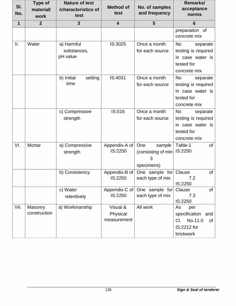
136 Sign & Seal of tenderer
Sl.
No.
Type of
material/
work
Nature of test
/characteristics of
test
Method of
test
No. of samples
and frequency
Remarks/
acceptance
norms
1 2 3 4 5 6
preparation of
concrete mix
V. Water a) Harmful
substances,
pH value
IS:3025 Once a month
for each source
No separate
testing is required
in case water is
tested for
concrete mix
b) Initial setting
time
IS:4031 Once a month
for each source
No separate
testing is required
in case water is
tested for
concrete mix
c) Compressive
strength
IS:516 Once a month
for each source
No separate
testing is required
in case water is
tested for
concrete mix
VI. Mortar a) Compressive
strength
Appendix-A of
IS:2250
One sample
(consisting of min
3
specimens)
Table-1
IS:2250
of
b) Consistency Appendix-B of
IS:2250
One sample for
each type of mix
Clause
7.2
IS:2250
of
c) Water
retentively
Appendix-C of
IS:2250
One sample for
each type of mix
Clause
7.3
IS:2250
of
VII. Masonry
construction
a) Workmanship Visual &
Physical
measurement
All work As per
specification and
Cl. No.11.0 of
IS:2212 for
brickwork

137 Sign & Seal of tenderer
Sl.
No.
Type of
material/
work
Nature of test
/characteristics of
test
Method of
test
No. of samples
and frequency
Remarks/
acceptance
norms
1 2 3 4 5 6
b) Verticality
and alignment
Physical
measurement
All work As per
specification and
Cl.No.6.3.4 of
IS:1905

138 Sign & Seal of tenderer
Section - T5
Technical specification for plastering and allied works
1. Scope
This part of the specification covers the requirements for plastering and allied works for
all types of masonry and concrete surfaces.
2. General requirements
2.1 The Contractor shall furnish all skilled and unskilled labour, plant, equipment,
scaffolding, materials, etc. required for complete execution ofthe work in accordance
with the drawings and as described herein and/or as directed by the Engineer.
2.2 The Contractor shall follow all safety requirements/rules during execution of the work.
2.3 I.S:1661 shall be followed as a general guidance for plastering work.
3. Codes and standards
3.1 All applicable standards, acts and codes of practice referred to shall be the latest
editions including all applicable official amendments and revisions. A complete set of all
these documents shall generally be available at Site with the Contractor.
3.2 In case of any conflict between this specification and those (IS Standards, Codes etc.)
referred to in clause 3.3, the former shall prevail.
3.3 Some of the applicable Indian Standards, Codes, etc. are referred to here below:
IS:383 Coarse and fine aggregates from natural sources for concrete
IS:712 Building limes
IS:1542 Specification for sand for plaster

139 Sign & Seal of tenderer
IS:1635 Code of practice for field slaking of Building lime and
preparation of putty
IS:2250 Code of practice for preparation and use of masonry mortar.
IS:2333 Plaster-of-paris
IS:2402 Code of practice for external rendered finishes
IS:2547 Gypsum building plaster
IS:3150 Hexagonal wire netting for general purpose
4. Materials
4.1 Materials namely, cement, sand, water, Coarse aggregate, shall be in accordance with
Technical Specifications for properties, storage and handling of common building
materials.
4.2 Lime for preparation of putty or neeru for punning work shall be according to class B&
C of IS: 712.
4.3 For rough cast plaster, coarse aggregate of size 6 to 12 mm shall be used in the finishing
coat. Coarse aggregate shall be as per IS: 383.
4.4 Gypsum, for use in plaster-of-paris punning work shall be according to IS:2333.
4.5 For lath plastering, galvanised hexagonal wire netting with wire 0.9mm dia and 12.5 mm
mesh conforming to IS:3150 shall be used.
5. Mortar
5.1 Unless otherwise specified cement & Fly ash (20% replacement ratio of cement with
fly ash): - sand mortar shall be used. Cement mortar shall be prepared by mixing
cement & fly ash (20% replacement ratio of cement with fly ash): and sand in specified

140 Sign & Seal of tenderer
proportions by volume. Sand shall be measured on the basis of its dry volume using
gauge boxes. Suitable allowance in quantity shall be made to cater for the bulkage.
Cement and fly ash shall preferably be measured by weight. For the purpose of
determining the corresponding volume, one cubic metre of cement shall be taken to
weigh 1440 Kg and one cubic metre of fly ash shall be taken to weigh 641 Kg (i.e. coal
ash)
5.2 The mixing of mortars shall be done in mechanical mixer. However, depending on
nature, magnitude and location of the work, the Engineer may relax the condition of
use of mechanical mixer and allow hand mixing.
Cement, fly ash and sand in the specified proportions shall be fed into the mixer and
mixed dry thoroughly in the mixer. Water shall then be added gradually and the wet
mixing continued for at least 3 minutes. Hand mixing shall be carried out on a clean,
water tight platform. Only that quantity of mortar, which can be used within 30 minutes
of its mixing, shall generally be prepared at a time. Care shall be taken, not to add
more water than that which shall bring the mortar to the consistency of a stiff paste.
IS: 2250 and IS:1661 shall be referred for ascertaining the quantity of water.
In case of cement mortar, the mortar that has stiffened because of evaporation of water from
the mortar may be retempered under special circumstances, with the approval of the
Engineer, by adding water as frequently as needed to restore the requirements of
consistency but this retempering shall be permitted only upto one hour from the time
of addition of cement.
Cement mortar shall be used as soon as possible after mixing and before it begins to set,
preferably within half an hour from the time water is added to cement during mixing
and in any case within one hour thereof.
Sweep mortar shall not be used.
6. Plastering
6.1 Mix proportion and plaster thickness
The mix proportion and thickness of plaster for various surfaces shall be as specified or shown
in the drawings. Unless otherwise specified the following shall be adopted.

141 Sign & Seal of tenderer
i. Ceiling plaster minimum 6mm thick cement mortar (1:4)
ii. Plaster on external/ rough face of
masonry work or concrete surface
18mm thick, cement mortar* (1:6)
iii. Plaster on plain face of masonry work
or concrete surface.
12mm thick, cement mortar*(1:6)
*In case of special application like water proofing surface, base course of decorative finish
etc., richer mix proportion not leaner than 1:4 shall be used.
6.2 Preparation of surface
The surface shall be cleaned of all dust, loose mortar droppings, traces of algae,
efflorescence and other foreign matter by water or by brushing. Smooth surfaces
shall be roughened by wire brushing, if it is not hard and by hecking when it is hard.
In case of concrete surface, if a chemical retarder has been applied to the framework,
the surface shall be roughened by wire brushing and all the resulting dust and loose
particles cleaned off and care shall be taken that none of the retarders is left on the
surface.
Trimming of projections, wherever necessary shall be done to achieve an even
surface. Ranking of joints in case of brickwork where necessary shall be done. The
masonry shall be allowed to dry out for sufficient period before plastering.
For ceiling plaster, the concrete surface shall be pock marked with a pointed tool to
ensure a proper key for the plaster.
The wall shall be dampened evenly and not soaked before application of plaster. If the
surface becomes dry in spots, such areas shall be moistened again.
6.3 Sequence of plastering operations
For external plaster, the plastering operations shall be started from the top and carried
downwards. To ensure even thickness and a true surface, plaster about 15 x 15 cm
shall be first applied horizontally and vertically, at not more than 2m intervals over the
entire surface to serve as gauges. The surfaces of those gauged areas shall be truly

142 Sign & Seal of tenderer
in the plane of the finished plastered surface. For internal plaster, the plastering
operations may be started wherever the building frame and cladding work are ready;
the temporary supports of the ceiling resting on the wall have been removed.
The first undercoat shall then be applied to ceilings. After the ceiling plaster is
completed and scaffolding for the same removed, the first undercoat on walls shall
then be applied.
After a suitable time interval as detailed under application of plaster, the second coat
(finishing coat) shall be applied, first to the ceiling and then to the walls.
Where corners and edges have to be rounded off, such rounding off shall be completed
alongwith the finishing coat to prevent any joint marks.
6.4 Application of plaster
6.4.1 Wall/vertical surface plaster
Unless otherwise stated, the plastering above 12mm thick shall be carried out in two
coats only.
i) The backing or first coat
The backing coat shall be 10 to 12 mm thick and carried to the full length of the
all or to natural breaking points like doors and windows. Before the rendering
coat hardens, it shall be roughened to provide mechanical key for the second
coat.
Masonry walls on which plaster is to be applied directly, shall be properly set
and cured with the joints raked to a depth of at least 10 mm. The rendering coat
shall be troweled hard and tight, forcing it into surface depressions to obtain a
permanent bond.
On smooth concrete walls, the surface shall be roughened and the rendering
coat shall be dashed on to ensure adequate bond. The dashing of the rendering

143 Sign & Seal of tenderer
coat shall be done using a strong whipping motion at right angles to the face of
the wall, or it may be applied with a plaster machine or cement gun.
ii) Finishing coat
Before starting to apply the finishing coat, the surface of the backing coat shall
be dampened evenly. The final plastered surface shall be cured and kept
continuously damp for minimum 7 days.
6.4.2 Ceiling plaster
Stage scaffolding shall be provided for ceiling plaster. This shall be independent of the
walls.
Projecting burrs of mortar formed due to gaps at the joints is shuttering shall be
removed. The surface shall be scrubbed clean with wire brushes. In addition, the
concrete surfaces shall be pock marked with a pointed tool at a spacing of not more
than 50 mm centres, the pocks being made not less than 3 mm deep, to ensure a
proper key for the plaster. The mortar shall be washed off and all surface cleaned of
all oil, grease, etc. and well wetted before the plaster is applied.
Ceiling plaster shall not be commenced until the slab above has been furnished and
centering has been removed. The average thickness of plaster shall not be less than
6 mm. The minimum thickness over any portion of the surface shall not be less than
5 mm.
The Surface shall be cured atleast twice a day for a minimum period of seven days.
6.4.3 Grooves in plaster
Where specified in drawings, rectangular grooves 12 to 20 mm wide and 8 to 10 mm
deep shall be provided in external plaster by means of timber battens or metal strips,
fixed on plaster when plaster is still green. Battens or strips shall be carefully removed
after initial set of plaster and broken edges and corners made good. All grooves shall
be uniform in width and depth and shall be truly plumb and correctly aligned.

144 Sign & Seal of tenderer
6.4.4 Drip course
Drip course wherever indicated in the drawings shall be provided at the time of
plastering to prevent travelling of water drops from the projections. Unless otherwise,
specified, projected strip form drip course shall be provided.
6.4.5 Metal lathing
The lathing shall be tightly stretched with the long way of the mesh across the supports
before nailing. This shall be secured with 25 mm galvanised steel staples or nails at
200 mm centres, if the studding is of wood and with 0.90 mm iron tying wire, if the
studding is of steel. Edges of lathing shall be lapped not less than 25 mm at the sides
and ends and wired together with galvanised wire of diameter not less than 1.25 mm,
every 100 mm between supports.
Before plastering, the surface of metal lathing shall be brushed over with thin cement
slurry or given a protective coat of bitumen oil paint.
6.4.5.1 Plastering to lathing
It shall be carried out in two coats. Mortars for the first coat shall be of stiff
consistency and applied as evenly as possible to give a uniform good cover to the
lathing. It shall be allowed to dry until all shrinkage movement has ceased before
the second coat is applied. Too much pressure shall not be used in applying plaster
to lathing to guard against its deflection.
6.4.6 Rough cast finish
The plaster base over which the rough cast finish is to be applied shall be done in
general as per clause no. 6.4 under sub head "Application of Plaster".
It shall be ensured that the base surface which is to receive rough cast mixture is in
plastic state. Coarse aggregate of size 6 to 12 mm shall be used in the finishing coat.
The grading and size shall vary according to the texture required.

145 Sign & Seal of tenderer
The rough cast mix shall be wetted and shall be dashed on the plaster base in plastic
state by hand scoop so that the mix gets well pitched into the plaster base. The mix
shall again be dashed over the vacant spaces, if any, so that the finished surface
represents a homogeneous surface of sand mixed with grovel. The surface shall be
cured for a minimum period of 7 days.
6.5 Punning work
6.5.1 Lime punning or Neeru finish
6.5.1.1 Materials
Lime putty: It shall be obtained by slaking lime with fresh water and sifting it. The
slaking shall be done in accordance with IS: 1635.
Neeru: It shall be obtained by mixing lime putty and sand in equal proportion and
chopped jute @ 4 Kg. per cu.m. of mortar. The mixture shall be properly ground to
a fine paste between two stones.
6.5.1.2 Application of punning
Lime punning consists in finishing the interior with a thin coat (3 mm) of fat lime putty
mixed with an equal amount of sand. Before actual use, putty shall be matured for
2 to 3 days.
The mortar for punning shall be applied in 3 mm thick layer just after the undercoat
has hardened. It shall be finished to a smooth surface by means of a plaster's trowel.
The curing shall be started as soon as the punning has hardened but in any case
not earlier than 24 hours after the punning has been completed. The punning shall
be kept wet for a period of seven days.
6.5.2 Plaster of paris punning
The plaster of paris (gypsum Anhydrous) conforming to IS: 2547 shall be used for
plaster of paris punning. The plaster of paris shall be mixed with water to a workable
consistency and shall be applied on the plastered surface and finished to a smooth

146 Sign & Seal of tenderer
surface by steel float. The finished surface shall be smooth and true to plane, slopes
or curves as required. The nominal thickness of the punning shall be 2 mm.
6.5.3 Neat cement punning
The plastered surface over which neat cement punning is to be done, shall be
uniformly treated over its entire area with a paste of neat cement and rubbed smooth,
so that the whole surface is covered with neat cement coating. The quantity of cement
applied shall be 1 kg. per sq. metre. Smooth finishing shall be completed with a float
immediately and in no case later than half an hour of adding water to the cement.
6.6 Trueness of plastering system
The finished plastered surface shall not show any deviation more than 4 mm when
checked with a straight edge of 2 metre length placed against the surface.
6.7 Thickness of plaster
The thickness of the plaster shall be measured exclusive of the thickness of key i.e.
grooves or open joints in brickwork. The average thickness of plaster shall not be less
than the specified thickness. The minimum thickness over any portion of the surface
shall not be less than the specified thickness by more than 3 mm for plaster thickness
above 12 mm and 1 mm for ceiling plaster. Extra thickness required in dubbing behind
rounding of the corners at junctions of wall or in plastering of masonry cornices etc. shall
be ignored.
6.8 Inspection and testing
a) The plastered surface shall be checked for following defects and the remedial
measures for the same shall be adopted as per IS: 1661. i) Blistering ii) Bound
failure or loss of adhesion
iii) Cracking
iv) iv) Crazing
v) Efflorescence
vi) Grinning

147 Sign & Seal of tenderer
vii) Irregularity of surface texture viii) Popping or blowing ix) Recurrent
surface dampness x) Softness or chalkiness
b) Trueness of the plaster shall be checked as per Clause no. 6.6
c) Thickness of the plaster shall be checked as per Clause no. 6.7
7. Pointing
7.1 The materials, preparation of mortar etc. shall be same as specified for cement plaster
works. The mix proportion shall not be leaner than 1:3, unless otherwise specified. For
all exposed brickwork or stone masonry work, self supporting double scaffolding, having
two sets of vertical supports shall be provided so as to avoid openings in the wall.
7.2 Preparation of surface
The joints shall be raked out properly to such a depth that the minimum depth of the
new mortar measured from either the sunken surfaces of the finished pointing or from
the edge of the brick shall not be less than 10 mm. Dust and loose mortar shall be
brushed out. Efflorescence, if any shall be removed by brushing and scraping. The
surface shall then be thoroughly washed with water, cleaned and kept wet before
commencement of pointing.
7.3 Application of mortar and finishing
The mortar shall be pressed into the raked out joints, with a pointing trowel, either
flush, sunk or raked, according to the type of pointing required. The mortar shall not
spread over the corner, edges or surface of the masonry. The pointing shall then be
finished with the proper tool according to the type of pointing required.
7.4 Type of pointing
7.4.1 Ruled pointing
Unless otherwise specified ruled pointing shall be adopted for all exposed brick/ block
masonry work. However, for rubble masonry works, recessed pointing shall be
adopted.

148 Sign & Seal of tenderer
The mortar shall be pressed into the raked out joints and shall be finished off flush
and then while the mortar is still green, a groove of shape and size as shown in
drawings shall be formed by running a forming tool straight along the centre line of
joints. This operation shall be continued till a smooth and hard surface is obtained.
The vertical joints shall also be finished in a similar way. The vertical joints shall make
true right angles at their junctions with the horizontal lines and shall not project beyond
the same. For recessed pointing in rubble masonry recess shall be provided along
the centre line of the joint profile.
7.4.2 Flush pointing
The mortar shall be pressed into the joints and shall be finished off flush and level with
the edges of the brick, tiles or stones so as to give a smooth appearance. The edges
shall be neatly trimmed with a trowel and straight edge. Unless otherwise specified,
flush pointing shall be adopted for drains and brick on edge paving.
7.4.3 Raised and cut pointing
Raised and cut pointing shall project from the wall facing with its edges cut parallel so
as to have a uniformly raised band about 6 mm raised and width 10 mm or more as
directed. The superfluous mortar shall be cut off from the edges of the lines and the
surface of the masonry shall also be cleaned off all mortar. Unless otherwise specified,
raised and cut pointing shall be adopted for stone masonry pointing, and shall be
provided along the Centre line of the joint profile.
7.5 Curing
The pointing shall be kept wet for 7 days.

149 Sign & Seal of tenderer
Section – T6
Technical specification for Street light poles
Section – T6
Technical specification street lighting poles
1. Scope
1.1. This specification covers the technical requirements of design, manufacture, testing
at manufacturer’s works, transportation delivery at site, erection, testing and
commissioning of tapered steel tubular street lighting poles suitable for base plate
mounting along with all accessories of efficient trouble free operation of street lighting.
1.2. The item offered under this specification shall be of proven design by way of Industrial
operation for a period of 3 years (min.)
1.3. The pole and accessories shall be complete in all respects and any device not
included in the specification but essential for satisfactory proper operations of the
equipment and also to comply with the requirements of the statutory authority. Safety
point of view shall be deemed specifically mentioned in the technical specifications
and data sheets or not.
2. Description of street lighting poles

150 Sign & Seal of tenderer
2.1. Street lighting poles shall be tapered steel tubular poles meeting the requirements of
IS:2173 and as per the dimensions specified and suitable for mounting outdoor street
light fixtures.
2.2. The material used for poles shall be MS. tubes confirming to IS:1239. The tubes
selected shall be as nearby circular as possible and free from harmful surface defects.
The ends shall be cut, dressed up and get ready for swaging. The depth of swaging
shall be maintained as per standard applicable to outer dia of the pole.
2.3. The dimensions of the poles shall be as close as possible to the design / drawing
enclosed and shall not exceed acceptable tolerances of:
(a) percent for outer diameter.
(b) Thickness shall not fall more than 10% of the thickness specified.
(c) The tolerance on the length of any section shall be 40 mm and on the overall length
by 25 mm.
(d) The height of single pole shall not fall below the calculated value by more than 7.5
percent.
(e) The finished pole shall not be out of straightness by more than 1/600 of its length.
2.4. The pole after manufacture shall be thoroughly cleaned both inside and outside and
the exterior portion is to be powered coated with Anti corrosive chemical resistant paint
as per IS:157 of approved brand and manufacture shall be used. Yellow primer coat
to be used shall be as per manufacturer’s specifications.
2.5. Standard earthing arrangement with integral junction box is to be provided in each
pole at a height of 500 mm above planting depth.
2.6. Mild steel base plate of size 300 x 300 x 12 mm shall be welded to the bottom of pole
with adequate size and qty of necessary foundation bolts.
2.7. The poles shall be complete with canopy arrangement to suit single / double cross
arm bracket to mount the fixture, as the case may be. The canopies are to be
fabricated out of mild steel tubes and to be supplied as separate attachments to
facilitate transportation and installation with ease.
151 Sign & Seal of tenderer
2.8. The pole shall be provided with a integral junction box for looping cable of appropriate
size and type for supply cable looping in and out. The size of the junction box shall
be adequate for easy termination of the cable. For specific poles at junction, where
more than one outgoing cables going on different routes are involved, the junction box
sizes shall be adequate to accommodate that many number of cable termination.
2.9. In addition, the integral junction box shall be provided with locking device and key.
One 10 amps double pole MCB shall be provided per fixture in the junction box for
fixture control along with connectors for looping in and out.
2.10. The junction box, control gear box shall be provided with entry and exit for flexible
cable from junction box to fixture shall be provided at suitable locations.
2.11. All the poles shall be identified with serial code numbers. The identification numbers
on the poles shall be painted on the pole by black paint and the letter height shall not
be less than 50 mm.
2.12. The poles shall be erected on road as indicated on the proposed section of roads
indicating its width and relative position of street lighting poles. The cross arm bracket
shall be mounted perpendicular to the length of the road and junction box on rear side
of the pole. All the poles shall be absolutely straight and in perfect plumb. These
poles shall be aligned properly along the edge of the road and with other poles.
2.13. The poles shall be erected on the concrete foundation with 4 nos. of adequate size of
foundation bolts as per pole manufacturer recommended with suitable base plate
above ground level.
2.14. HDPE Pipe sleeves one meter long, shall be provided for each cable during erection
of the poles.
2.15. If required by the owner, the following random sample tests shall be performed to
ensure quality of the poles. (a) Tensile test as per IS: 2713.
(b) Chemical analysis of the material to ensure sulphur and phosphorous content within
limit of 0.06 percent each as per IS:228.
(c) Deflection test to ensure that temporary deflection due to applied load shall not
exceed limit of 157.5 mm.

152 Sign & Seal of tenderer
(d) Permanent set test to ensure that the permanent set, after application and release
of specified load, measured from zero position, does not exceed 13 mm.
(e) Drop test on tapered poles to ensure that poles do not show signs of telescoping or
loosening of joints, if dropped vertically with butt end (bottom end) downwards from
a height of 2 M on to a hard wood block 150 mm thick laid on a concrete foundation.
Section – T7
Technical specification for 33 kV XLPE cables
Section – T7
Technical specification for 33 kV XLPE cables
Contents
Clause no. Description Page nos.
1. Scope .................................................................................................................... 171
2. Electrical system .................................................................................................... 171
3. Standards .............................................................................................................. 171
4. General construction ............................................................................................. 171
5. Inspection & testing ............................................................................................... 172
6. Data & Information ................................................................................................. 173
7. Packing .................................................................................................................. 173
TECHNICAL SPECIFICATION FOR 33 KV XLPE CABLES

153 Sign & Seal of tenderer
1. Scope
1.1 This specification covers the requirements of design, manufacture, inspection, testing and
supply of 33KV XLPE (E) Armoured aluminium Cables.
2. Electrical system
Nominal Voltage : 33 KV + 6%
Frequency : 50 Hz. + 3%
No. of phases : 3 phases, 3 W
3. Standards
3.1 The Cables shall comply with conform to the latest editions of the following Indian Standard Specifications.
IS 7098 (Part II) : Cross-linked polyethylene insulated PVC sheathed cables for
working voltages from 3.3KV up to and including 33
KV.
IS 3975 : Mild steel wires, strips and tapes for
armouring of cables.
IS 10418: 1982 : Drums for electric cables.
IS 10810 : Methods of test for cables.
IS 1554 (Part I) : PVC Cables for voltage up to and including 1100
volts.
IS 8130 : Conductors for insulated electric cables.
IS 5831 : PVC insulation and sheath of electric cables.
IS 3975 : Mild steel wires, strips and tapes for armouring of
cables.
4. General construction
4.1 The XLPE cables shall be suitable for laying in trays, trenches, ducts, conduits and buried underground installation with uncontrolled backfill and possibility of flooding by water. These shall have following constructional features.
4.2 Cables for 33 KV system shall be with Aluminium Conductor, XLPE insulated, screened, sheathed, armoured and overall PVC sheathed as detailed below:

154 Sign & Seal of tenderer
4.3 The construction of the conductors shall be stranded and compacted circular for all cables.
4.4 All cables rated 33KV shall be provided with both conductor shielding, insulation shielding / screening. The conductors shall be provided with non-metallic extruded semi-conducting shielding.
4.5 The core insulation shall be with cross-linked polyethylene unfilled insulating compound. It shall be free from voids and shall withstand all mechanical and thermal stresses under steady state and transient operating conditions.
4.6 The insulation shielding shall consist of non-metallic extruded semi-conducting compound in combination with a non-magnetic metallic screening of copper. The insulation screen shall be strippable without application of heat.
4.7 The conductor screen, XLPE insulation and insulation screen shall all be extruded in one operation by ‘Tripple Extrusion’ process to ensure perfect bonding between the layers. The core identification shall be with coloured strips or by printed numerals.
4.8 The inner sheath shall be applied over the laid up cores by extrusion and shall conform to the requirements of Type ST2 compound of IS : 5831. The extruded inner sheath shall be of uniform thickness of size not less than 0.7 mm for all sizes of cables
4.9 The armouring shall be by galvanised steel strips type.
4.10 The outer sheath for the cables shall be applied by extrusion over the armouring and shall be of PVC compound conforming to the requirements of Type ST2 compound of IS 5831. To protect the cable against rodent and termite attack, suitable chemicals shall be added into the PVC compound of outer sheath.
4.11 The dimensions of the insulation, armour and outer sheathing materials shall be governed by values given in Tables 1, 3 and 4 of IS 7098 Part – II
5. Inspection & testing
5.1 Representative of the Owner shall have free access to vendor’s works to inspect, expedite
and witness shop tests. Any materials or works found to be defective or
which does not meet the requirements of this specification will be rejected and shall be
replaced at Vendor’s cost.
5.2 All routine tests shall be carried out on the cables as per relevant Indian Standard
Specifications and will be witnessed by the Owner.

155 Sign & Seal of tenderer
5.3 Routine test certificates shall be submitted for all the cable drums also copy Type test
certificates for the type tests carried out on identical cables shall be furnished to the
Owner for reference and records.
6. Data & Information
6.1 Vendor shall furnish with the bid full constructional data along with ratings and other
parameters of the cables. Deviations, if any, shall be brought out clearly in the bid.
7. Packing
7.1 The cables shall be supplied in standard drum lengths duly wound on non-returnable
wooden / Steel drums.
7.2 Vendor shall ensure that the bending radius of cables are not less than 12 times their
overall diameters when wound on drums. Both ends of the cables shall be sealed.
7.3 Following information shall be printed on the flange of each cable drum a)
Type
b) Size
c) Voltage grade
d) Length in meters
e) ISI mark
f) Gross weight
g) Direction of rolling
7.4 Guaranteed technical particulars - Power cables
Sl.No Description Particulars
1 Type of cable To be provided by
vendor
2 Voltage grade
Sl.No Description Particulars
3 Max. Conductor temperature
4 Material of construction
a Conductor
b Conductor insulation
c Inner sheathing
d Armouring
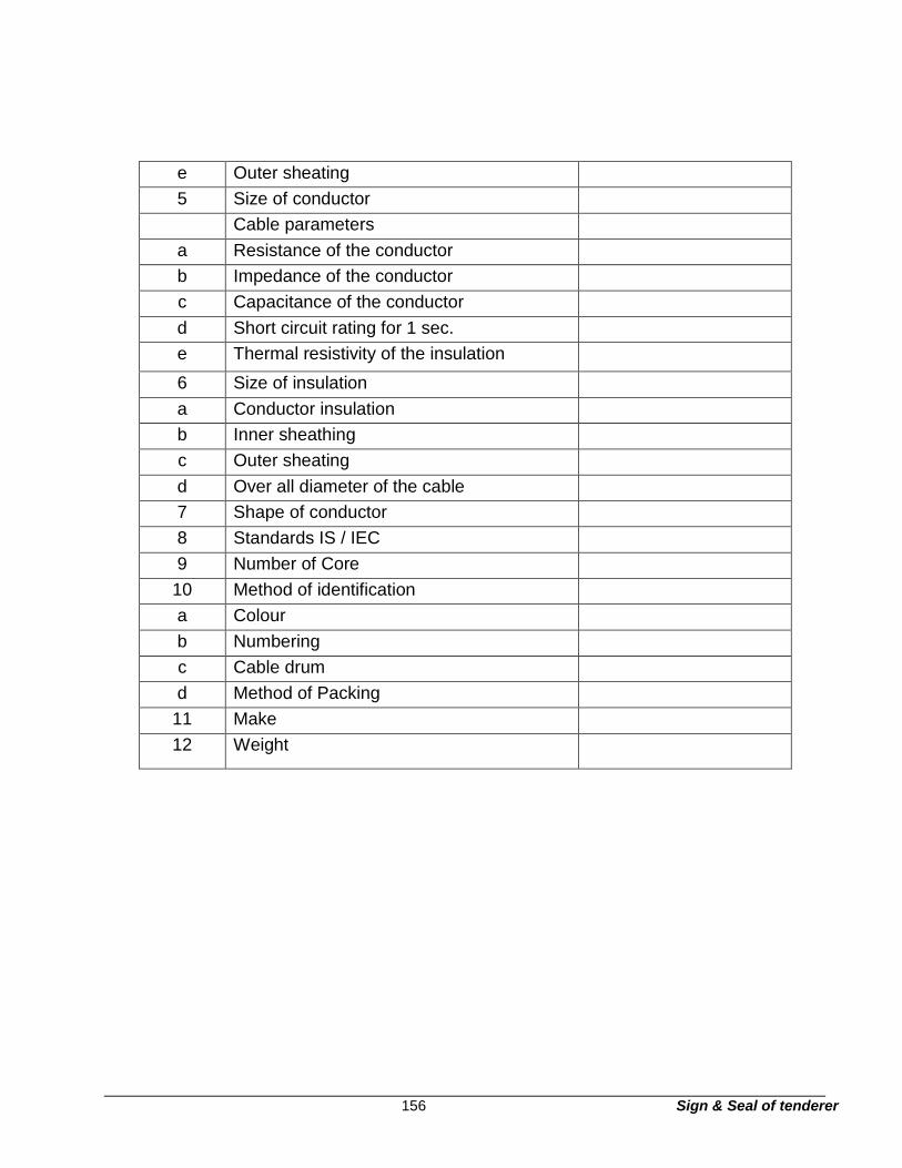
156 Sign & Seal of tenderer
e Outer sheating
5 Size of conductor
Cable parameters
a Resistance of the conductor
b Impedance of the conductor
c Capacitance of the conductor
d Short circuit rating for 1 sec.
e Thermal resistivity of the insulation
6 Size of insulation
a Conductor insulation
b Inner sheathing
c Outer sheating
d Over all diameter of the cable
7 Shape of conductor
8 Standards IS / IEC
9 Number of Core
10 Method of identification
a Colour
b Numbering
c Cable drum
d Method of Packing
11 Make
12 Weight

157 Sign & Seal of tenderer
Section – T8
Technical specification for 11 kV XLPE cables
1. Scope
This specification covers the requirements of design, manufacture, inspection, testing
and supply of 11 KV XLPE (E) Armoured aluminium Cables.
2. Electrical system
Nominal Voltage : 11 KV + 6%
Frequency : 50 Hz. + 3%
No. of phases : 3 phases, 3 W
3. Standards
3.1. The Cables shall comply with conform to the latest editions of the following Indian
Standard Specifications.
IS 7098 (Part II) : Cross-linked polyethylene insulated PVC sheathed
cables for working voltages from 3.3KV up to and
including 33 KV.
IS 3975 : Mild steel wires, strips and tapes for armouring of
cables.
IS 10418: 1982 : Drums for electric cables
IS 10810 : Methods of test for cables
IS 1554 (Part I) : PVC Cables for voltage up to and including 1100 volts.
IS 8130 : Conductors for insulated electric cables
IS : 1255 : Code of practice for installation & maintenance of
power cables upto & including 11 KV rating
IS 5831 : PVC insulation and sheath of electric cables
IS 3975 : Mild steel wires, strips and tapes for armouring of cables.
4. General construction
158 Sign & Seal of tenderer
4.1. The 11 KV XLPE (E) cables shall be suitable for laying in trays, trenches, ducts,
conduits and buried underground installation with uncontrolled backfill and possibility
of flooding by water. These shall have following constructional features.
4.2. Cables for 11 KV system shall be with Aluminium Conductor, XLPE insulated,
screened, sheathed, armoured and overall PVC sheathed as detailed below:
4.3. The construction of the conductors shall be stranded and compacted circular for all
cables.
4.4. All cables rated 11 KV shall be provided with both conductor shielding, insulation
shielding / screening. The conductors shall be provided with non-metallic extruded
semi-conducting shielding.
4.5. The core insulation shall be with cross-linked polyethylene unfilled insulating
compound. It shall be free from voids and shall withstand all mechanical and thermal
stresses under steady state and transient operating conditions.
4.6. The insulation shielding shall consist of non-metallic extruded semi-conducting
compound in combination with a non-magnetic metallic screening of copper. The
insulation screen shall be strippable without application of heat.
4.7. The conductor screen, XLPE insulation and insulation screen shall all be extruded in
one operation by ‘Triple Extrusion’ process to ensure perfect bonding between the
layers. The core identification shall be with coloured strips or by printed numerals.
4.8. The inner sheath shall be applied over the laid up cores by extrusion and shall conform
to the requirements of Type ST2 compound of IS : 5831. The extruded inner sheath
shall be of uniform thickness of size not less than 0.7 mm for all sizes of cables
4.9. The armouring shall be by galvanised steel strips type.
4.10. The outer sheath for the cables shall be applied by extrusion over the armouring and
shall be of PVC compound conforming to the requirements of Type ST2 compound of
IS 5831. To protect the cable against rodent and termite attack, suitable chemicals
shall be added into the PVC compound of outer sheath.

159 Sign & Seal of tenderer
4.11. The dimensions of the insulation, armour and outer sheathing materials shall be
governed by values given in Tables 1, 3 and 4 of IS 7098 Part – II
4.12. HV cable termination should be heat shrink type with adequate suitable size and
joining of main conductor cores using suitable size of ferrules / mechanical connectors
with range taking feature should be provided.
4.13. The heat shrinkable component shall be light in weight and shall be made of specially
formulated cross linked polymeric material with excellent tracking & erosion resistance
characteristic. Environmentally sealed system for splicing dielectric shielded power
cable
4.14. Heat shrinkable stress control tube to be provided over conductor to reduce stress,
The stress control tube has to be in electrical contact with the outer insulation screen
of the cable.
4.15. Earth Continuity between armoured wires to be provided using tinned copper braid of
adequate cross section to endure proper earthing of the connection along with
armoured wire support ring. The material of support ring to be steel (G.I.) for 3 core
Cable and aluminium for 1 core cable, the clip should be worm drive type for securing
the earthing braid tightly with adequate size & quantity.
4.16. The insulation over the conductor area should be maximum three layers of heat
shrinkable insulating tube are to be provided. The thickness of the heat shrinkable
tube after installation should not be less than 1.2 times the insulation thickness of the
cable. For outer semi conductor screening of the joint suitable heat shrinkable dual
wall tubes which are co-extruded are to be provided
5. Inspection & testing
5.1. Representative of the Owner shall have free access to vendor’s works to inspect,
expedite and witness shop tests. Any materials or works found to be defective or
which does not meet the requirements of this specification will be rejected and shall
be replaced at Vendor’s cost.

160 Sign & Seal of tenderer
5.2. All routine tests shall be carried out on the cables as per relevant Indian Standard
Specifications and will be witnessed by the Owner.
5.3. Routine test certificates shall be submitted for all the cable drums also copy Type test
certificates for the type tests carried out on identical cables shall be furnished to the
Owner for reference and records.
6. Data & Information
6.1. Vendor shall furnish with the bid full constructional data along with ratings and other
parameters of the cables. Deviations, if any, shall be brought out clearly in the bid.
7. Packing
7.1. The cables shall be supplied in standard drum lengths duly wound on non-returnable
wooden / Steel drums.
7.2. Vendor shall ensure that the bending radius of cables are not less than 12 times their
overall diameters when wound on drums. Both ends of the cables shall be sealed.
7.3. Following information shall be printed on the flange of each cable drum
a) Type
b) Size
c) Voltage grade
d) Length in meters
e) ISI mark
f) Gross weight
g) Direction of rolling
7.4. Guaranteed technical particulars - Power cables
Sl.No Description Particulars
1 Type of cable To be provided by
vendor
2 Voltage grade
3 Max. Conductor temperature

161 Sign & Seal of tenderer
4 Material of construction
a Conductor
b Conductor insulation
c Inner sheathing
d Armouring
e Outer sheating
5 Size of conductor
Cable parameters
a Resistance of the conductor
b Impedance of the conductor
c Capacitance of the conductor
d Short circuit rating for 1 sec.
e Thermal resistivity of the insulation
6 Size of insulation
a Conductor insulation
b Inner sheathing
c Outer sheating
d Over all diameter of the cable
7 Shape of conductor
8 Standards IS / IEC
9 Number of Core
10 Method of identification
a Colour
b Numbering
c Cable drum
d Method of Packing
11 Make
12 Weight

162 Sign & Seal of tenderer
Section – T9
Technical specification for 1.1kV XLPE armoured U.G cables
1. Scope
1.1. This specification covers the requirements of design, manufacture, inspection, testing
and supply at site of 1.1KV grade XLPE insulated Armoured power and control cables.
2. Electrical system
Nominal Voltage : 415V + 6% Frequency
: 50 Hz. + 3%
No. of phases : 3 phase, 4 W
3. Standards
5.0. The 1.1KV grade Power & Control Cables conform to the requirements of the latest Indian
Standard Specifications including but not limited to the following:
IS 7098 (Part I) : Cross-linked polyethylene insulated PVC sheathed
cables for working voltages from up to and including 3.3
KV.
IS 1554 : PVC Insulated (heavy-duty) electric cables:
Part 1 for working voltages up to and
including 1100 V
IS 3975 : Mild steel wires, strips and tapes for armouring of
cables.
IS 10418: 1982 : Drums for electric cables.
IS 10810 : Methods of test for cables
IS 1554 (Part I) : PVC Cables for voltage up to and including 1100
volts.
IS 8130 : Conductors for insulated electric cables
IS : 1255 : Code of practice for installation & maintenance of power cables upto &
including 11 KV rating.
IS 5831 : PVC insulation and sheath of electric cables
IS 3975 : Mild steel wires, strips and tapes for armouring of cables
163 Sign & Seal of tenderer
4. General construction
4.1. The cables shall be suitable for laying in trays, trenches, ducts, conduits and buried
underground installation with uncontrolled backfill and possibility of flooding by water.
These shall have following constructional features.
4.2. All power and control cables for use on low voltage system shall be heavy duty type,
1100V grade with aluminium / copper conductor, XLPE / PVC insulated, PVC inner
sheathed, armoured and overall PVC sheathed as detailed below:
4.3. The construction of the conductors shall be SOLID for aluminium conductor cables up
to 10 mm sq. and for copper conductor cables up to 2.5 mm sq. For cables above 10
mm sq. and for copper cables above 2.5 mm sq. the conductor shall be STRANDED.
Conductors of nominal cross sectional area less than 10 sq.mm shall be circular only.
Conductors of nominal cross section area 16 sq.mm and above may be circular or
sector shaped.
4.4. The core insulation shall be with PVC applied over the conductor by extrusion and shall
conform to the IS 1554.
4.5. The core insulation with XLPE applied over the conductor by extrusion and shall
conform to the IS 7098 part – I.
4.6. Control cables having 6 cores and above shall be identified with prominent and
indelible arabic numerals on the outer surface of the insulation. Colour of the numbers
shall be white with a spacing of maximum 500 mm between two consecutive numbers.
4.7. The inner sheath shall be applied over the laid-up cores by extrusion and shall be of
PVC conforming to the requirements of type ST2 PVC compound per IS 5831. The
extruded inner sheath shall be of uniform thickness of size not less than 0.5 mm up to
16 sq.mm, 0.8 mm from 25 sq.mm upto 120 sq.mm and 1.0 mm above 120 sq.mm
conductor size. Taped inner sheath shall also be acceptable.

164 Sign & Seal of tenderer
4.8. For multi core cables, the armouring shall be by single round galvanised steel wires
where the calculated diameter below armouring does not exceed 13 mm and
galvanised steel strips where this dimension is greater than 13 mm. Requirement and
methods of tests for armour material and uniformity of galvanisation shall be as per IS
3975 and IS 2633.
4.9. The outer sheath for the cables shall be applied by extrusion and shall be of PVC
compound and conforming to the requirements of type ST 2 compound per IS 5831.
To protect the cables against rodent and termite attack, suitable chemicals shall be
added into the PVC compound of the outer sheath.
4.10. The dimensions of the insulation, armour and outer sheath materials shall be governed
by values given in IS 1554 (Part I).
5. Inspection & testing
5.1. Representative of the Owner shall have free access to vendor’s works to inspect,
expedite and witness shop tests. Any materials or works found to be defective or which
does not meet the requirements of this specification will be rejected and shall be
replaced at Vendor’s cost.
5.2. All routine tests shall be carried out on the cables as per relevant Indian Standard
Specifications and will be witnessed by the Owner.
5.3. Routine test certificates shall be submitted for all the cable drums also copy Type test
certificates for the type tests carried out on identical cables shall be furnished to the
Owner for reference and records.
6. Data & information
6.1. Vendor shall furnish with the bid full constructional data along with ratings and other
parameters of the cables. Deviations, if any, shall be brought out clearly in the bid.
7. Packing

165 Sign & Seal of tenderer
7.1. The cables shall be supplied in standard drum lengths duly wound on non-returnable
wooden drums.
7.2. Vendor shall ensure that the bending radii of cables are not less than 12 times their
overall diameters when wound on drums. Both ends of the cables shall be sealed.
7.3. Following information shall be printed on the flange of each cable drum.
a) Type
b) Size
c) Voltage grade
d) Length in meters
e) ISI Mark
f) Gross weight
g) Direction of rolling
7.4. Guaranteed technical particulars - Power cables
Sl.No Description Particulars
1 Type of cable To be provided by
vendor
2 Voltage grade
3 Max. Conductor temperature
4 Material of construction
a Conductor
b Conductor insulation
c Inner sheathing
d Armouring
e Outer sheating
5 Size of conductor
Cable parameters
a Resistance of the conductor
b Impedance of the conductor
c Capacitance of the conductor
d Short circuit rating for 1 sec.
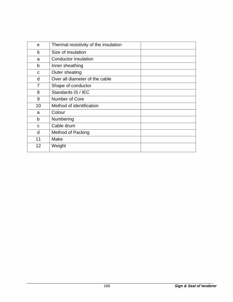
166 Sign & Seal of tenderer
e Thermal resistivity of the insulation
6 Size of insulation
a Conductor insulation
b Inner sheathing
c Outer sheating
d Over all diameter of the cable
7 Shape of conductor
8 Standards IS / IEC
9 Number of Core
10 Method of identification
a Colour
b Numbering
c Cable drum
d Method of Packing
11 Make
12 Weight

167 Sign & Seal of tenderer
Section – T10
Technical specification of 11 kV Ring main unit (out-door)
The 11 kV Ring Main Units (RMU) should be SCADA COMPATIBLE for our future-use be
self-contained totally insulated unit constitutes the MV component of the MV/LV transformer
substation or the branching point of an MV network. The RMU regroups, in a single Epoxy
enclosure, all the medium voltage functions enabling transformers to be connected, supplied
and protected.
Ringmaster, should be covering a wide range of options with an outdoor IP54 design and
ranting up to 12 kV, 630A; 21 KA, 3 sec, and for all applications, from basic transformer
protection to sectionalising with remote control using FTU and tele control & automation can
be added in future without and modifications
It also provides the control and monitoring of networks from remote central point. Location of
problems and re-configuration is completed with minimum downtime & without manual
intervention.
1. Standards
♦ Common clause for high voltage switchgear and low
voltage switchgear IEC 694
♦ Self-contained medium voltage apparatus IEC 298
♦ High voltage circuit breakers IEC 56
♦ AC switches and ear thing switches IEC 129
♦ Switches and disconnectors IEC 265
♦ Combined switch/disconnectors IEC 420
♦ Current transformer IEC 185
♦ Voltage transformer IEC 186
♦ High voltage fuses IEC 282
♦ Classification of degrees of protection for enclosures IEC 529

168 Sign & Seal of tenderer
The equipment proposed be designed, manufactured and tested in compliance with IEC
recommendations but not limited to the following standards:
2. General characteristics in accordance with the IEC standards
Description
Self-contained unit
Degree of protection -
Enclosure
IP 54
- Operating mechanism IP 2X
3. Electrical characteristics
A. Description
Rated voltage kV rms 12kV
Operating voltage kV rms 11kV
B. Insulation level:
Rated withstand voltage at power frequency: 50Hz/1 min kV rms 38kV
Rated impulse withstand voltage: 1.2/50µs kV peak 95kV
C. Network and bus bars
Rated current A 630A
Rated short-time current kA 3 sec 21kA
Making capacity for switch-disconnectors and earthing switches 52.5kAp
Internal arc withstand kA 1 sec 16kA
Transformer Tee-Off
Rated current A Up to 630 A
The RMU should be suitable to operate in the ambient temperature between -25°C and
+40°C.
All breaking units, including earthing switches, are contained in enclosure filled with
SF6, sealed for life according to the IEC standard EE Appendix Class III.

169 Sign & Seal of tenderer
4. Site condition
The equipment covered under this specification is for outdoor installation and should
be suitable for use at the sites for the prevailing climatic conditions.
a) Temperature: The reference ambient temperature is to be taken as 48ºC as per IS
9676.
i) Maximum ambient air temp : 50ºC
ii) Maximum daily average ambient temp
b) Relative Humidity
: 40ºC
Maximum : 100% non condensing
Minimum :
10%
c) Average Annual rainfall :
750mm
d) Average no of rainy days/annum :
50
e) Average no of thunderstorm days/annum
: 40
f) Altitude : suitable up to 1000 m
The atmosphere is heavily polluted, laden with mild acid and dust in suspension during
the dry months and is subjected to fog in cold months. Heavy lightening occurs in the
area during rainy months.
All equipments are to be designed to withstand seismic forces, corresponding to an
acceleration of 0.1g.
5. Technical specification

170 Sign & Seal of tenderer
The Ring Main Master to feed units is equipped with manually operated VCB panel
without metering and outgoing circuit breakers and isolators, as per B.O.Q.
5.1. Isolators
The isolators offered shall conform to IEC-265 as amended to date. The isolator shall
be SF6 insulated, triple pole, spring assisted hand operated type with quick break
contacts. The isolator shall be contained in sealed SF6 enclosure made of Metallised
Epoxy / Stainless Steel. SF6 gas pressure gauge shall be provided for pressure
indication purpose.
Each of the Isolators shall be provided with LEDs for “Live Cable” Indication.
The operating handle shall have the three positions “ON”, “OFF”, and “EARTH” which
shall be clearly marked with suitable arrangement to padlock in any position. A safety
arrangement for locking shall be provided by which the isolator operation shall be
prevented from “ON” position to “EARTH” position or vice versa in a single operation.
Integral cable test terminals for test plug with clear identification mark shall be
provided. The interlocks shall be so arranged that, the cable test terminals will be
accessible only in the “EARTH” position of the isolator.
To facilitate testing of cables, it shall be possible to bring the isolator to OFF position
while the test plugs are kept inserted, but operation to ON position shall be prevented
so long the cable testing is in progress.
Cable testing shall be possible without disconnecting the Cables or opening the Cable
compartment.
The isolator shall be capable of breaking full load current and a fault making of 52.5KA
peak.
Isolators are to be operated manually. However, there must be provision in the
isolator to fix motor to operate the isolator electrically via 24V DC batteries in a Remote
Terminal Interface.
5.2. SF6 circuit breaker

171 Sign & Seal of tenderer
5.2.1. The tee-off unit shall consist of 11KV, 630 Amps SF6/Vacuum Breaker (for controlling
transformer), load breaking and fault breaking and fault making type fitted with three
200 Amps continuously rated air insulated bus bars and arrangement for cable to the
primary side of the transformer.
5.2.2. The Tee-off circuit breaker shall be suitable for manual closing and opening and also
for provision for remote tripping in future. The Circuit Breaker mechanism shall be co-
related with a self-powered OC/EF relay.
5.3. The operating mechanism shall be direct hand operated trip free with a mechanically
operated indicator, positively coupled to the operating mechanism to indicate whether
the breaker is in the closed or in the open position.
5.4. The tee-off Circuit Breaker unit shall be provided with accessories for tripping such as CT
operated series trip coils for over current and earth fault protection.
5.5. Breaker shall be provided with a shunt trip coil suitable for 230V AC supply.
5.6. Current Transformer: The Ratio of the CTs will be suitable for controlling transformer as
to be specified in consultation with State Vidyut Nigam. The VA burden of the CTs
shall be sufficient to supply the energy required by the relay for normal operation and
tripping of the circuit breaker.
5.7. Protection System: The protection system should be provided with the provision of
suitable self-powered relays having scheme for both over current & earth fault. The
protection system shall be a self-powered relay which shall require no external power
source or batteries. It must have improved operation and control with the Relay
settings clearly displayed on the front of the panel. Manual reset flag shows separate
tripped on fault for either phase or earth fault conditions. It should have the provision
for the trip test on circuit breaker. The ‘trip inhibit’ facility should allow the Relay to be
tested without tripping the circuit breaker.
5.8. The free standing metal housing shall be designed to withstand internal pressure and
external mechanical loads without distortion. Where required the SF6 gas insulated
switchgear housing shall have an over pressure relief device vented to the rear side
of the equipment. An operating mimic diagram shall be provided on the front side of

172 Sign & Seal of tenderer
Ring Main Unit. Each unit shall be provided with lifting facility of proven design for
easy handling.
5.9. Handle operated ‘spring charged’ mechanical operation be provided.
5.10. Local operation selector switch be provided.
5.11. SF6 Insulation: Switchgear housing be completely gas tight. In the power compartment
provision be made for filling up the gas at site.
5.12. A manometer should be provided to indicate the healthy state of SF6 gas pressure
inside the tank. SF6 gas pressure inside the tank shall not be more than 1 bar at 20
Deg Centigrade
5.13. General finish
5.13.1. The equipment be totally enclosed, metal clad, vermin and dust proof suitable for
tropical climate use as detailed above.
5.13.2. Painting: The surface of all metallic parts shall be thoroughly cleaned, scrapped and
degreased preferably by shot blasting or any other treatment. The exterior surface
shall be given two coats of rust resisting red oxide primer conforming to IS 2074:1992
and final two coats of weather resisting battleship grey enamel paint. The paint shall
withstand the operating conditions described above and equipment shall not show
any sign of the rust formation.
6. Operation and interlocking
6.1. All operations shall be from front of the equipment via spring assisted mechanism.
The Ring Main Unit and SF6/Vacuum Circuit Breaker for Tee-off should be provided
with a series trip coil for tripping. It shall be possible to operate the switches and circuit
breaker manually and spring assisted mechanism shall ensure speed of operation of
switches.

173 Sign & Seal of tenderer
6.2. Operation handle shall be considered as part of the unit and should be provided with
each Ring Main Unit.
6.3. Load break switches and earthing switches be fully interlocked to ensure that
operation is carried out in correct sequence. Movement of operating handle against
interlock shall not by any means originate, store or activate the energy mechanisms.
Padlocking facility be provided for operation of load switch and earthing switch. Safety
of operation be ensured by interlocks.
6.4. Simultaneously closing of the main switch and earth switch: This interlock be integral
part of the operating mechanism. Also separate operating shafts be provided for
operation of earthing switch and main switch for the same purpose.
6.5. The fully interlocked integral test facilities are to be provided underneath the units, so
that access to the test terminals is achieved only by removal of a cover.
6.6. The SF6 insulated isolators and SF6 breaker operating mechanisms be totally
enclosed and self lubricating type. The manually operated handle be mounted in front
of the isolators and so designed that the operation is complete by one movement
without any undue stain on the operator.
6.7. All mechanical interlock shall be robust so as not to give any way during normal
operation.
6.8. The tripping of breaker unit should be provided with push button.
7. Secondary wiring
7.1. The secondary wiring supplied for the equipment shall consist of non-deteriorating fire
proof superior grade stranded copper PVC wires suitably colored and fitted with
numbered ferrules at both ends.
7.2. Wiring be terminated with ring type ferrules with ferrule numbers marked at both ends
of wiring. CT wiring be marked with additional distinct Red tags on both ends. All
secondary wiring be terminated by using reputed make terminal blocks.

174 Sign & Seal of tenderer
8. Earthing arrangement
a) It should be easily possible to test the cables including the Tee-off (in case of RMU)
by a simple earthing arrangement.
b) Equipment earthing of GI / Copper strips of adequate size be provided
8.1. A mechanical ‘ON/OFF’ indicator be provided on SF6 insulated isolators and SF6
Breaker to indicate whether switch is ON of OFF.
8.2. SF6 insulated switches be fitted with correct sequence device having “ON/OFF’ and
re-set and test position and shall have provision for padlocking operating handle.
9. Cable boxes
9.1. The isolators and SF6 Breaker should be provided with suitable and identical cable
boxes for connection 3 core, 11KV XLPE cables of size up to 400 mm2 approaching
vertical from below. The cable boxes be so located at convenient height to facilitate
easy cable jointing work.
9.2. The access for the isolator cable box be from side and the access for the Tee-Off SF6
Breaker cable box be from rear side and distanced of bottom level of wiping gland
from ground shall be maintained at 310 mm (minimum).
9.3. The cable boxes be with detachable front cover for ease of termination & be
interlocked with switch position (i.e. when isolator is in Earth / OFF position).
9.4. The design of the cable box shall be such that any type of jointing methods such as
heat shrinkable/push on type/cold shrinkable type termination’s can be adopted.
10. Earthing
10.1. All ring main units should have a special earth bar with a sectional area of not less
than 100 mm² run along the whole of metal enclosed switch structure, each end being
connected to the main earthing system where metal cases are used on instruments
these shall be connected to this bar by conductors of not less than 16 mm² section

175 Sign & Seal of tenderer
11. Guaranteed technical particulars for 11 kV outdoor RMU
Sl.No Description Particulars
1 General : To be furnished by contractor
1.1 Applicable Standard.
1.2 Type
1.3 Rated Voltage.
1.4 Highest System Voltage
1.5 Phase
1.6 Frequency.
1.7 Rated Normal Current.
1.8 Rated Short Circuit Current Capacity
1.9 Rated Breaking Current Capacity (min)
1.1 Rated Making Capacity
1.11 Insulation Level :
1.12 Minimum Gas Pressure
1.13 Dimension of RMU ( H X W X D )(Maximum Limit)
1.14 Material
a Tank
b Outer Structure
c Outdoor enclosure
1.15 Degree of Protection
a High Voltage live parts, SF6, VCB
b Front Cover Mechanism
Sl.No Description Particulars
c Cable Compartment
1.16 Internal Arc for main Tank & Cable Chamber
1.17 Temperature Category
1.18 Whether RMU has provision for sensors for temperature
compensated pressure measurement the relevant gas
compartment to monitor the pressure of SF6 gas
1.19 Weight of RMU complete with operating mechanism
1.20 Position of the Power Cable entry of the RMU
2 Vacuum Circuit Breaker
2.1 Normal Voltage
2.2 Highest System Voltage
2.3 Frequency
2.4 No. of Poles
2.5 Rated Current
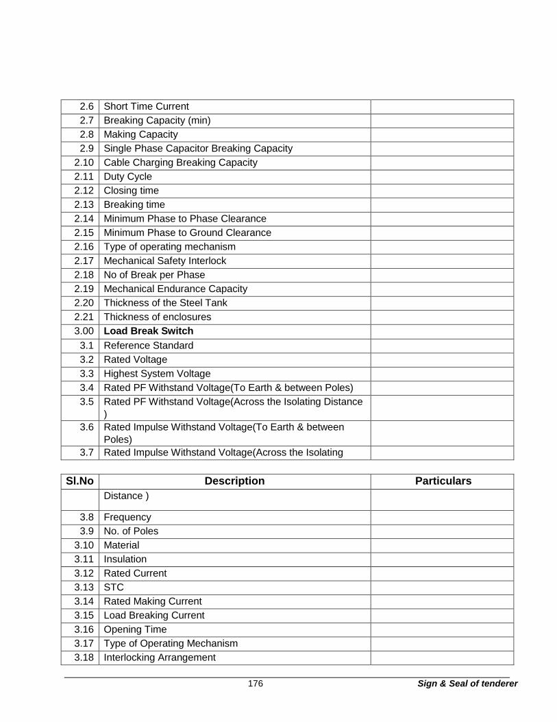
176 Sign & Seal of tenderer
2.6 Short Time Current
2.7 Breaking Capacity (min)
2.8 Making Capacity
2.9 Single Phase Capacitor Breaking Capacity
2.10 Cable Charging Breaking Capacity
2.11 Duty Cycle
2.12 Closing time
2.13 Breaking time
2.14 Minimum Phase to Phase Clearance
2.15 Minimum Phase to Ground Clearance
2.16 Type of operating mechanism
2.17 Mechanical Safety Interlock
2.18 No of Break per Phase
2.19 Mechanical Endurance Capacity
2.20 Thickness of the Steel Tank
2.21 Thickness of enclosures
3.00 Load Break Switch
3.1 Reference Standard
3.2 Rated Voltage
3.3 Highest System Voltage
3.4 Rated PF Withstand Voltage(To Earth & between Poles)
3.5 Rated PF Withstand Voltage(Across the Isolating Distance )
3.6 Rated Impulse Withstand Voltage(To Earth & between
Poles)
3.7 Rated Impulse Withstand Voltage(Across the Isolating
Sl.No Description Particulars
Distance )
3.8 Frequency
3.9 No. of Poles
3.10 Material
3.11 Insulation
3.12 Rated Current
3.13 STC
3.14 Rated Making Current
3.15 Load Breaking Current
3.16 Opening Time
3.17 Type of Operating Mechanism
3.18 Interlocking Arrangement

177 Sign & Seal of tenderer
3.19 Fault Passage Indicator
3.20 Make
3.21 Type
3.22 Provision of Live Line Detector(Y/N)
3.23 Spacing between Live part to Earth
3.24 Spacing between Phases
3.25 Spacing between Fixed & Moving Contacts position
4.00 Mechanical Endurance Capacity
4.1 Temperature Rise
4.2 Type of Operating Mechanism for closing
4.3 LBS provided with Earth Switch ( Y / N)
4.4 Earth Switch
4.5 Reference Standard
4.6 Rated Voltage
4.7 Highest System Voltage
4.8 Rated PF Withstand Voltage(To Earth & between
4.9 Rated PF Withstand Voltage(Across the Isolating Distance )
4.10 Rated Impulse Withstand Voltage(To Earth Poles)
4.11 Rated Impulse Withstand Voltage(Across Distance )
4.12 Frequency
4.13 No. of Poles
4.14 Material
4.15 Insulation
4.16 Rated Current
4.17 STC
4.18 Rated Making Current
4.19 Opening Time
Sl.No Description Particulars
4.20 Type of Operating Mechanism
4.21 Interlocking Arrangement
4.22 Spacing between Fixed & Moving Contacts in open
position
5.00 Current Transformer
5.1 Make
5.2 Type
5.3 Voltage Grade
5.4 Reference Standard
5.5 Primary Insulation level (PF rms / impulse peak)

178 Sign & Seal of tenderer 5.6 One minute PF withstand Voltage on Secondary

179 Sign & Seal of tenderer 5.7 Class of Insulation

180 Sign & Seal of tenderer 5.8 Frequency

181 Sign & Seal of tenderer 5.9 Ratio

182 Sign & Seal of tenderer 5.10 Class of Accuracy

183 Sign & Seal of tenderer 5.11 Rated burden

184 Sign & Seal of tenderer 5.12 STC for 1 second

185 Sign & Seal of tenderer 5.13 Continuous Over Load in percentage

186 Sign & Seal of tenderer 6.00 Bus Bar

187 Sign & Seal of tenderer 6.1 Material

188 Sign & Seal of tenderer 6.2 Maximum Current Density

189 Sign & Seal of tenderer 6.3 Minimum clearance (Phase to Phase)(AIS portion)

190 Sign & Seal of tenderer 6.4 Minimum clearance (Phase to Ground)(AIS portion)

191 Sign & Seal of tenderer 6.5 Cross sectional area of the Bus

192 Sign & Seal of tenderer 6.6 Current Rating of Bus

193 Sign & Seal of tenderer 6.7 Type of Insulation

194 Sign & Seal of tenderer 6.8 Minimum Creepage Distance of Bus support

195 Sign & Seal of tenderer 6.9 Insulator(AIS portion)

196 Sign & Seal of tenderer 7.00 Vacuum Interrupter

197 Sign & Seal of tenderer 7.1 Make

198 Sign & Seal of tenderer 7.2 Type & Model

199 Sign & Seal of tenderer 7.3 Current Rating

200 Sign & Seal of tenderer 7.4 STC

201 Sign & Seal of tenderer
7.5 Breaking Capacity
7.6 Mechanical Endurance Capacity
7.7 Electrical Endurance Capacity
7.8 Minimum Electrical Life at STC
8.00 Earth Bus
8.1 Material
8.2 Size (Minimum)
Sl.No Description Particulars
9.00 Numerical Relay
9.10 Applicable Standard
9.2 Make
9.3 Type
9.4 Model No
9.5 Current setting range for Over Current(IDMTL)
9.6 Current setting range for Earth fault(IDMTL)
9.7 Instantaneous Current setting range for Over
9.8 Instantaneous Current setting range for Earth
9.9 O/C & E/F Characteristic
9.10 No. of Element
9.1 Secondary Current
9.1 Type of Display unit
9.1 Burden
9.1 Whether Draw out type(Y/N)
10.0 Painting
10.1 Support Structure
10.2 Mimic
10.3 Outdoor part
10.4 Thickness
11.0 Control Wire
11.1 Make
11.2 Voltage Grade
11.3 Size
11.4 (i) CT Circuit
11.5 (ii) Other Circuit
11.6 Colour
11.7 Accessories
11.8 Spring Charging Handle
11.9 VCB operating Handle
11.10 Guarantee of the total equipment including any
11.11 integral part of the equipment

202 Sign & Seal of tenderer
Section – T11
Technical specification for 11 kV Outdoor unitized substation
1. Substation with 500 KVA, 11KV/433V (Oil cooled Type Transformer)
Bill of material for Outdoor type package substation 500 KVA, 11 KV/433 V (Oil
Cooled Type Transformer)
Outdoor type package substation with facility for internal lighting, earthing, padlocks
etc. Connection will be by 3 core, 11KV XLPE cables of size up to 400 sq.mm. Cable
termination kits for RMU are in our scope of supply (within enclosure).
2. Package substation
Package substation will have the following equipments:
2 way Non - Extensible unit RMU with 1 nos. 630 A load break switch and 1
no. 200A tee off with SF6 circuit breaker / VCB self-powered with O/C + E.F.
Relay, M.V Metering arrangement with digital electronic meter, C.T' etc. to
complete as required to entire satisfaction of Engineer-in-charge.
• IDMT RELAY for Circuit Breakers – Self Powered, Merlin Gerin type VIP35.
• The Ring Switches and Tee-Off Circuit Breaker are provided with Integrated Earthing
Switches with Making Capacity.
• M.V Metering with Digital type KWH meter along with C.T, P.T, control wiring and
other accessories required.
• Neon cable indicator for ring switch and circuit breaker
• Integral earthing facility for ring switches.
• Shunt trip coil rated for 230 V AC
• Trip push button for T-Off Circuit breaker
• SF6 Gas pressure indicator
• Padlocking facility
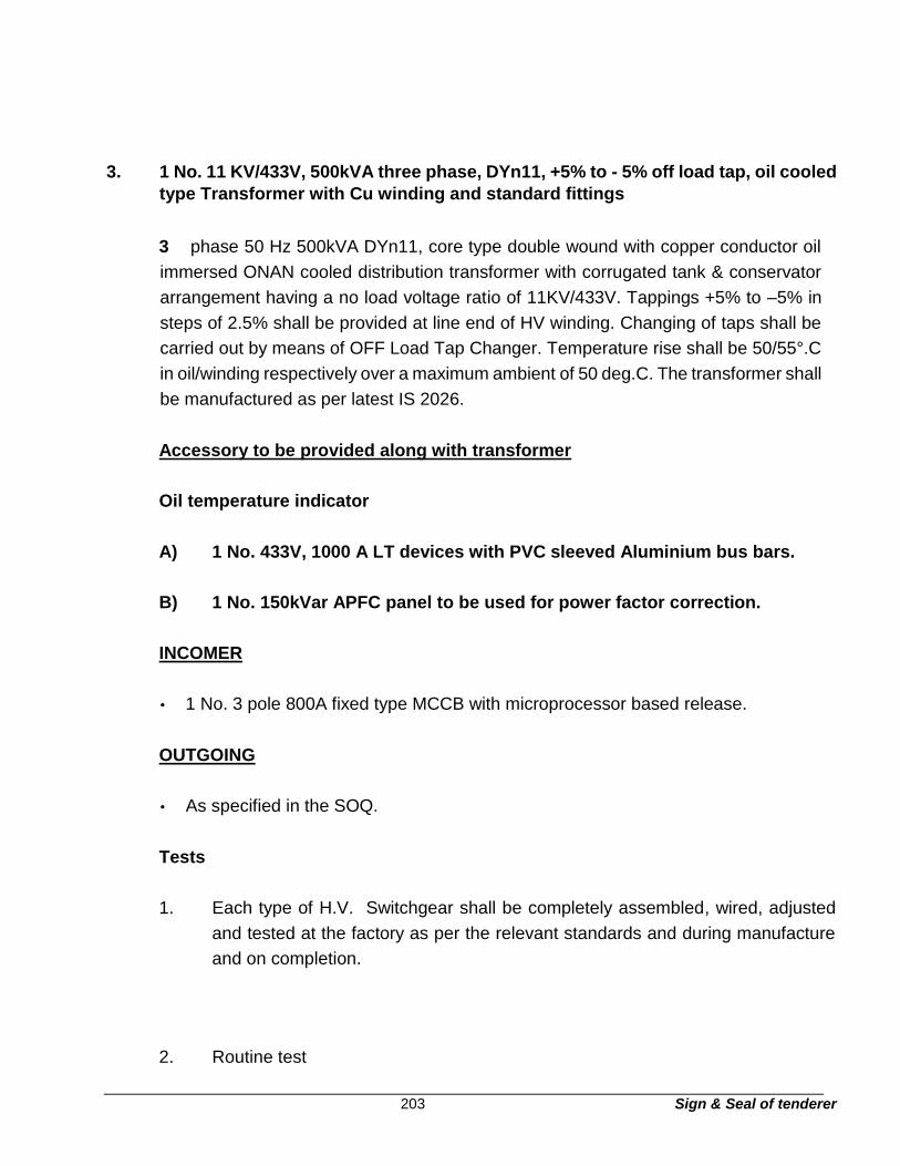
203 Sign & Seal of tenderer
3. 1 No. 11 KV/433V, 500kVA three phase, DYn11, +5% to - 5% off load tap, oil cooled
type Transformer with Cu winding and standard fittings
3 phase 50 Hz 500kVA DYn11, core type double wound with copper conductor oil
immersed ONAN cooled distribution transformer with corrugated tank & conservator
arrangement having a no load voltage ratio of 11KV/433V. Tappings +5% to –5% in
steps of 2.5% shall be provided at line end of HV winding. Changing of taps shall be
carried out by means of OFF Load Tap Changer. Temperature rise shall be 50/55°.C
in oil/winding respectively over a maximum ambient of 50 deg.C. The transformer shall
be manufactured as per latest IS 2026.
Accessory to be provided along with transformer
Oil temperature indicator
A) 1 No. 433V, 1000 A LT devices with PVC sleeved Aluminium bus bars.
B) 1 No. 150kVar APFC panel to be used for power factor correction.
INCOMER
• 1 No. 3 pole 800A fixed type MCCB with microprocessor based release.
OUTGOING
• As specified in the SOQ.
Tests
1. Each type of H.V. Switchgear shall be completely assembled, wired, adjusted
and tested at the factory as per the relevant standards and during manufacture
and on completion.
2. Routine test

204 Sign & Seal of tenderer
The tests shall be carried out in accordance with IEC 60298 include but not
necessarily limited to the following:
i. Withstand voltage at power frequency for all current carrying
parts including wiring
ii. Measurement of resistance of the main circuit iii. Gas leakage
test
iv. Withstand voltage on auxiliary circuits
v. Operation of functional locks, interlocks, signaling devices and auxiliary
devices
vi. Suitability and correct operation of protections, control instruments and
electrical connections of the circuit breaker operating mechanism (primary
& secondary injection) vii.
Verification of wiring
viii. Visual inspection
Routine test shall be carried out on all equipment such as circuit breakers, current
transformers, relays, meter etc. as per relevant standards.
3. Type test
Type Test Certificates for the following tests as per IEC Standards 60056, 60129,
60265, 60298, 60529 and 60694 shall be submitted along with offer:
i. Impulse test with breaker inside the cubicle ii.
Temperature rise test with breaker inside the cubicle
iii. Short circuit test with breaker inside the breaker iv.
Dielectric tests
v. Test of apparatus i.e. circuit breaker and earthing switch vi.
Internal arc fault test at 16kA for 1 sec.

205 Sign & Seal of tenderer
4. Specification for 11/0.433 oil type distribution transformer
4.1. General information
All equipment and material shall be designed manufactured and tested in accordance
with the latest applicable Indian Standard, IEC standard and CBIP manuals except
where modified and / or supplemented this specification.
Equipment and material confirming to any other standard, which ensures equal or
better quality, may be accepted. In such case copies of English version of the standard
adopted shall be submitted.
The electrical installation shall meet the requirement of Indian Electricity Rules as
amended up to date, relevant IS code of practice and Indian electricity act. In addition
other rules of regulations applicable to the work shall be followed in case any
discrepancy the most stringent and restrictive one shall be binding.
The Transformer offered shall in general comply with the latest issues including
amendments of the following Indian standards but not restricted to it.
4.2. Code and standards
The transformer shall comply with the latest edition of the following and other relevant
Indian Standards / Manual:
IS 335: Insulating oil
IS 1271: Thermal evaluation and classification of electrical insulation
IS 2026: Power Transformers
IS 2099: Bushing for alternative voltages above 1000V
IS 2705: Current transformer
IS 3347: Dimension for porcelain transformer bushings. IS
3637: Gas operated relays
IS 3639: Fitting and accessories for power transformers
IS 4201: Application guide for CTs
IS 6600: Guide for loading of oil immersed transformer
206 Sign & Seal of tenderer
IS 8478: Application guide for ON load tap changers
IS 8468: On load tap changers
IS 10028: Code practice for selection, installation and maintenance of
transformer
IS 13947: LV switchgear and control gear – Part – I General rules
CBIP Manual on transformers
IS 2074: Ready mixed paint, air drying red oxide, zinc chrome priming
IS 5: Color of ready mix paint
IS 2932: Enamel synthetic, exterior a) under coating b) Finishing
IS 3347: Dimension of porcelain transformer bushing for use in
very heavily polluted atmosphere
Indian Electricity Rules: 1956
Indian Electricity Act: 1910
The Electricity Act: 2003
In case of conflict between the above standards and this specification, the requirements
of this specification shall prevail.
Transformer shall also conform to the provisions of the latest revisions of the Indian
Electricity rules and any other statutory regulations currently in force.
4.3. Design criteria
11kV/ 433 volt distribution transformer shall be a part of Factory Assembled
PreFabricated substation which will be housed inside the enclosure.
The transformers shall be installed in hot, humid tropical atmosphere. All equipment
accessories and wiring shall be provided with tropical finish to prevent fungus growth.
The transformers shall be capable of continuous operation of rated output under the
operating conditions of voltage and frequency variations as per statutory limits
governed by relevant Indian Standard and Indian Electricity Rules, 1956 with latest
amendments in force.
The transformer shall conform to best engineering practice.

207 Sign & Seal of tenderer
The transformers shall be capable of withstanding the short circuit stresses due to
terminal fault between phase to phase and phase to ground on one winding with full
voltage maintained on the other windings for a minimum period of three seconds.
The transformers shall be free from annoying hum or vibration. The design shall be
such as not to cause any undesirable interference with radio or communication
circuits.
The equipment offered shall be suitable for continuous satisfactory operation inside the
USS.
5. Specific requirement
5.1. Voltage ratio: No load voltage 11000/433 volts within tolerance as stipulated in IS:
2026.
5.2. Rating: The transformer shall have a continuous rating as specified at any of the
specified tapping position and with the maximum temperature rise specified. The
rated KVA shall be the product of the rated voltage in kV, the corresponding rated
current and the phase factor 1.73. When the transformer is operated with the rated
primary voltage applied to the terminals of the primary winding, the apparent power
(kVA) at the terminals of the secondary winding, when carrying the rated secondary
current differs from rated kVA by an amount corresponding to the regulation of the
transformer and is the product of the actual secondary voltage, the rated secondary
current and phase factor 1.73
5.3. System: 11000 volts A.C. supply, on H.V. side and 433 Volts on L.V. side with
variations, as per statutory variation governed by relevant Indian Standard and Indian
Electricity Rules, 1956 with latest amendments in force. The 11kV neutral and L.V.
neutral is earthed solidly at each transformer substation. The transformers will be
connected in a system consisting of both overhead and underground mains (both on
HV and LV sides)

208 Sign & Seal of tenderer
5.4. Temperature Rise: The maximum temperature rise at the specified maximum
continuous output shall not exceed 40°C by thermometer in the hottest portion of the
oil or 50°C measured by resistance of winding above ambient temperature.
5.5. Type of Load: The transformer shall be suitable for carrying load within temperature
rise indicated in the Indian Standard specification IS: 6600 ‘Guide for loading of oil
immersed Transformer’.
5.6. Overloads: The transformers shall be suitable for carrying overload within
temperature rise indicated in IS: 6600 ‘Guide for Loading of oil immersed Transformer’
5.7. Connections: H.V. Delta and L.V Star connected with neutral brought out on the
secondary side for connection to earth; Vector group DYn11 of IS:2026.
5.8. Tank
The transformer tank and cover shall be fabricated from robust M.S. plate steel without
pitting and shall have adequate thickness, with external cooling tubes or radiators.
The tank and cover shall be of welded construction. All seams shall be welded and
where practicable they shall be double welded. All edges shall be double welded. The
tank wall shall be reinforced by stiffener to ensure rigidity, so that it can withstand
without any deformation (a) mechanical shock during transportation (b) oil filling. All
removable covers shall be provided with weatherproof, hot oil resistant, resilient
gaskets. The design shall be such as to prevent any leakage of water into or oil from
the tank.
The tank shall be subjected to a pressure test of 0.35 kg/cm2 with hot oil for 12 hours
when the transformer is complete with all fittings. During the test average oil
temperature shall be maintained at 45ºC above Ambient temperature throughout test
period by circulating suitable current in HV winding and short circuiting L.V. winding.
There shall be no leakage of oil during or after the test. Also there shall be no
deflection at all when the pressure is removed. The purchaser’s representative may
be present during these tests for which advance intimation shall be given. Otherwise
test Certificate for this test shall be produced by the supplier in triplicate before
dispatching the units.

209 Sign & Seal of tenderer
Air release plugs shall be provided on main tank top cover to cover entire area suitably.
Inspection covers shall be provided to facilitate individual inspection, without lifting the
tank cover, for the following:
a) Connection of primary winding to cable box/disconnection chamber bushings.
b) Connection of secondary winding to cable box / disconnection chamber bushings.
c) Main tank center for core/winding inspection.
6. Oil
6.1 The necessary quantity of new transformer oil according to IS: 335 shall be supplied
filled in the transformer tank & up to a height above the minimum filling mark of
conservator tank. The Supplier shall furnish the relevant technical particulars and test
certificates of the oil supplied. An additional 10% of the total quantity of oil required
shall be supplied loose along with the transformer.
6.2 Leakage of oil: Suitable approved type of material such as “Neoprene” which has an
oil proof agent, as specified in IS: 1866 shall be provided at all joints to prevent leakage
of oil during continued operation or during transportation.
6.3 Drying-out: The transformer winding shall be thoroughly dried out & kept immersed
in oil to avoid any further drying out by the purchaser & to facilitate immediate
commissioning of the transformer on receipt.
6.4 Clamping of leads: All leads from the coils to the terminals shall be suitably clamped
to prevent snagging and fouling with other parts and the tank.
6.5 Phase marking: Phase markings as per IS: 2026 punched on small non-corrosion
metallic tags shall be permanently fixed for H.V. just below the cable box or on some
suitable removable part of the tank and above L.V. Bushings. Phase markings tags
shall be properly fixed with proper alignment.
7. Core and coil

210 Sign & Seal of tenderer
7.1 The core shall be constructed from high grade, cold rolled, non-ageing, low loss, high
permeability, grain oriented, cold-rolled grain oriented silicon steel laminations. The
transformer shall be so designed as to have minimum humming noise. The
percentage harmonic potentials with the maximum flux density under any conditions
shall be such that capacitors connected in the system shall not be overloaded.
7.2 The coils shall be manufactured from electrolytic copper conductor and fully insulated
for rated voltage. The winding shall be cross over coil type with minimum 4 coils
per phase.
7.3 Insulating material shall be of proven design. The insulating materials shall be class
“A” or above specified as per IS: 1271. Coils shall be so insulated that impulse and
power frequency voltage stresses are minimum.
7.4 Transformers will be connected at the end of 11 kV
7.5 The coil assembly shall be supported suitably between adjacent sections by insulating
spaces & barriers. Brazing shall be arranged to ensure a free circulation of the coil &
to reduce the hot spot of the winding.
7.6 All leads from the windings to the terminal board and bushings shall be rigidly
supported to prevent injury from vibration or short circuit stresses. Guide tube shall
be used wherever practicable.
7.7 The core and coil assembly shall be securely fixed in position so that no shifting or
deformation occurs during movement of transformer. The core and coil assembly
shall be capable of withstanding without injury, the thermal and mechanical effects of
short circuit at the terminals of any winding as per IS:2026.
8. Tests for oil type distribution transformer
Routine Tests (As Per IS 2026, Clause 16.1.2)
The following tests are to be carried out as per IS 2026, clause 13.2.
i. Measurement of winding resistance
211 Sign & Seal of tenderer
ii. Measurement of voltage ratio & check the voltage vector relationship
iii. Measurement of impedance voltage (principal tapping), short circuit impedance
& load loss all shall be corrected to a temperature of 75 °C
iv. Measurement of no load loss and current
v. Separate source withstand voltage
vi. Induced over voltage withstand
vii. Dielectric test of oil
Type Tests (As per IS 2026, clause 16.1.1)
Type Test reports for following tests shall have to be submitted along with the offer.
i. Short circuit test
ii. Acoustic noise level test
iii. Oil leakage test by application of pressure
Miscellaneous
1. All components parts and auxiliary equipment such as bushings, tap changing
gear, etc. shall be routine tested as per relevant Indian Standards.
2. The manufacturer shall have the necessary laboratory grade instruments and
equipment for carrying out all routine and type tests and get these calibrated at
frequent intervals.
3. The transformers (including tap change gear) shall be capable of withstanding
without damage the thermal and mechanical effects of short circuits at the
terminals of any winding or the periods as provided by latest IS:2026/Part1/1977.
The manufacturer shall supply the calculation for short circuits in case required
by purchaser.
A. SPECIFICATION FOR LT SYSTEM
LT compartment shall be suitable to house following equipment,
- Bus bar connection from transformer to MCCB’s

212 Sign & Seal of tenderer
- The provision for solid connection with aluminium strips with heat shrinkable
sleeves from Main L.T Bus bar to each compartment of MCCB so as to enable the
executing agency at site for connection with MCCB & when required. - Cable glands
for outgoing feeders
B. SPECIFICATION FOR ENCLOSURE FOR PACKAGE SUBSTATION
The package substation shall have the following features.
1. Enclosure for the entire package substation shall be of Galvanised Iron Sheet
painted with the colour approved by Client / his authorized representative
2. Pre-Fabricated Substation shall be factory assembled only. NO site assembly
shall be allowed
3. Separate compartment for 11 kV RMU, Distribution Transformer & LT
Switchgear. Door of the HT and LT compartment shall be designed such as
complete door is divided into minimum fourfold / parts vertically for minimum
space requirement while opening
4. Enclosure - Protection degree of the enclosure for MV and LV compartments
should be IP54 in accordance with IEC recommendation (Publication n 529).
Protection degree for Transformer compartment is IP 34
5. Ventilation apertures are sufficient for natural ventilation (Class K10)
6. There should be proper earthing arrangement for the entire substation i.e. 11 kV
RMU, Distribution Transformer, LT Switchgears along with the enclosures.
7. Design of Transformer Compartment shall be such to accommodate oil type
transformers for required sizes.
8. Non-metallic barrier shall be provided between MCCB.

213 Sign & Seal of tenderer
9. Non-metallic phase separator shall be provided between the three phases
connected to MCCB.
10. Before energization of package substation shall have to be approved by Chief
Electrical Inspector Rajasthan and Rajasthan State Electricity Authorities. It is
responsibility of contractor to make changes as per requirement of Chief
Electrical Inspector and Rajasthan State Electricity Authorities without any time
and cost implication to the client.

214 Sign & Seal of tenderer
Section – T12
Technical specification for LED Street light
fitting
1. Scope
1.1. This specification covers the requirement of design, manufacture, testing and delivery
at site of the light fittings (Non-flameproof type).
2. Description of light fittings
2.1. Street light fittings shall be suitable for LED comprising of single piece die cast
aluminium alloy LM6 housing with name of the manufacturer shall be Engraved, pot
optics reflector, finished in powered coat of approved colour.
2.2. LED lumens output efficiency should be more than 100 lumens per watt or higher.
Necessary Test Certificate from Govt. Approved Lab / NABL accredited Lab / UL to
substantiate lumen output as per LM 79 must be furnished for evaluation.
2.3. The control gear compartment shall be wired with copper would ballast, power factor
improvement capacitor and mains connector. The total housing shall be weather proof
and shall prevent entry of insects. A pair of purity anodised aluminium side reflector
shall be mounted inside the lamp compartment for high photometry efficiency.
2.4. Necessary INSITU Thermal report to be submitted from the manufacturer indicating
maximum temperature point on LED array. Which shall not exceed junction
temperature Specified in LM 80 report at life of higher than 50000 hrs.
2.5. The luminaire shall have the Ultra Violet stabilized Heat resistant clear toughened
glass protector with impact resistance IK07 rating.
215 Sign & Seal of tenderer
2.6. The LED fitting power consumption should be within the tolerance of ±5% with LED
colour temperature shall be 5700K or higher
2.7. Street light shall have Ingress Protection of IP 66 Rated for Both for Optical & Electrical
Compartment. Necessary supporting document for Test Report for the same need to
be furnished from any Govt. Approved/NABL accredited Laboratory.
2.8. Luminaire should consist of Universal Voltage driver to operate from 140V to 270V 50
Hz application within necessary built in protection against short circuit, over voltage,
overload and wrong wiring protection. Driver should have Surge Protection as per
IEC 6100-4
2.9. The electronic driver shall be dimmable driver (analog 0-10V) suitable for dimming the
luminaires to various power levels. Typical requirement is 0-100% lighting levels.
2.10. The fixture should be designed so as to have lumen maintenance of at least 70% at
the end of 50,000 hours with life of 50000 hrs with CRI of LED shall be more than 70.
2.11. The LED should be provided with structured LED array for optimized roadway
photometric distribution with photometric lenses designed to optimize application
efficiency and minimal glare
2.12. The internal wiring used inside the luminaire, shall be low smoke halogen free, fire
retardant and MCB protection shall be provided in input side.
2.13. The LED fitting should be supported with necessary Type Test Certificate of luminaire
from Govt. accredited Test Lab/ERTL/ NABL shall be submitted.
2.14. The cable entry to the fixture shall be protected by rubber grommetted inlet against
ingress of water. Suitable type of connector shall be provided inside the control gear
compartment for incoming wire termination.
2.15. The construction of the fixture shall be such that lamp replacement shall be easily
possible by releasing toggles and opening acrylic cover which is hinged to one end.
The mounting arrangement shall be suitable for mounting fixture firmly on G.I. pipe
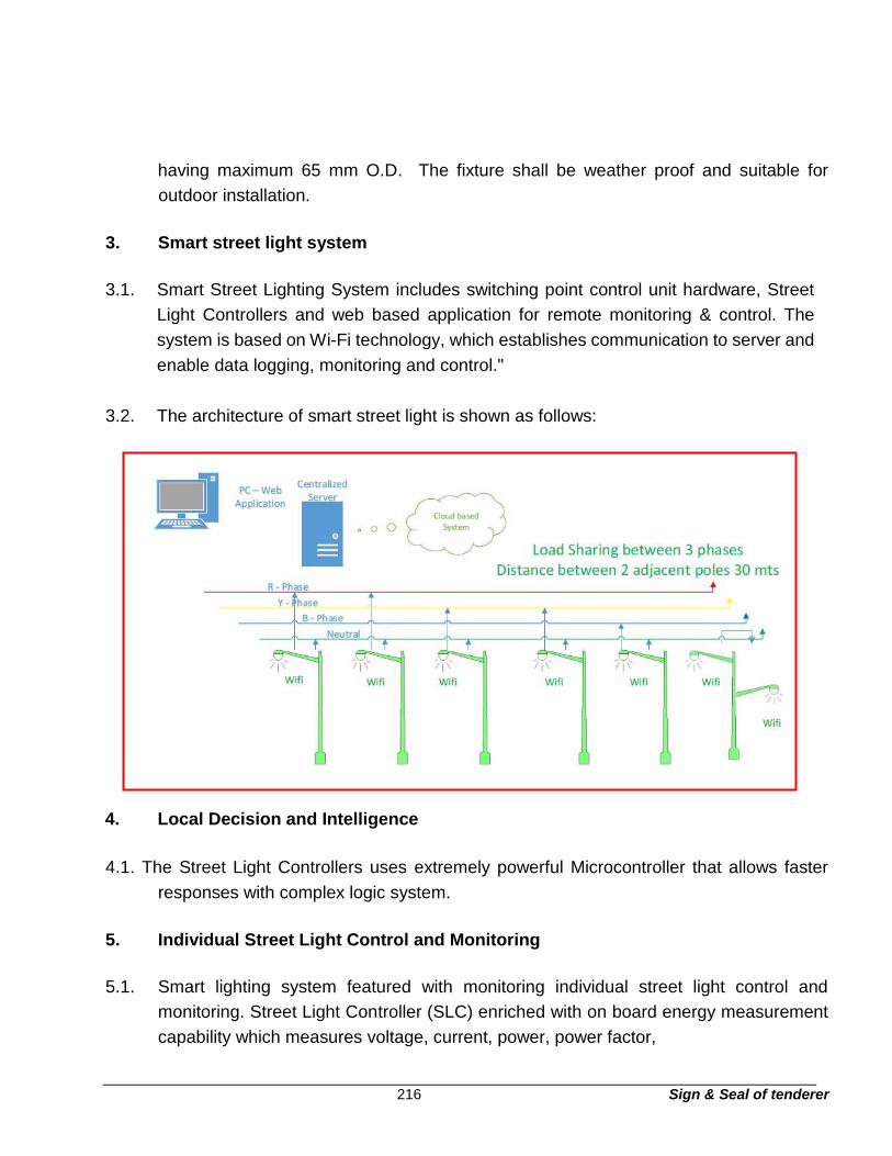
216 Sign & Seal of tenderer
having maximum 65 mm O.D. The fixture shall be weather proof and suitable for
outdoor installation.
3. Smart street light system
3.1. Smart Street Lighting System includes switching point control unit hardware, Street
Light Controllers and web based application for remote monitoring & control. The
system is based on Wi-Fi technology, which establishes communication to server and
enable data logging, monitoring and control."
3.2. The architecture of smart street light is shown as follows:
4.1. The Street Light Controllers uses extremely powerful Microcontroller that allows faster
responses with complex logic system.
5. Individual Street Light Control and Monitoring
5.1. Smart lighting system featured with monitoring individual street light control and
monitoring. Street Light Controller (SLC) enriched with on board energy measurement
capability which measures voltage, current, power, power factor,
4 . Local Decision and Intelligence

217 Sign & Seal of tenderer
active energy, apparent energy, frequency. SLC controls ON / OFF / Dimming of
streetlights
6. Group Level Street Light Control and Monitoring
6.1. Smart lighting system supports group level street light control and monitoring in single
go. Street Lights under cluster can be made ON/OFF/Dim in single click.
7. Simple and Remote Configuration
7.1. The street Light Controller can be easily and remotely configured from easy web
interface. Configuration allows user to set operating modes, ON / OFF timings, RTC
configuration, Updating GPS locations, Astronomical Clock, Motion Detectors
8. Connectivity Options
8.1. Street Light Controllers communicate with central server through Wi-Fi as backhaul
network.
9. Google Maps and Asset Tracking
9.1. Supports Asset tracking of every streetlight Switching Point Controller through GPS
coordinates. Enables user to locate Switching Point Controller through Google maps.
As an option the system is provides user to track streetlights through GPS coordinate.
10. Heat Maps
10.1. Heat map feature in Web application software enables user to identify system faults
easily through user-friendly heat maps.
11. System Security
11.1. System uses secured communication (SSL) methods between server and gateway.
Web application provides different user privileges to differentiate admin user with
general users. System is full fail proof with password protection.
12. Street Light Controller (SLC) Details-

218 Sign & Seal of tenderer
12.1. Street Light Controller (SLC) can be installed at the TOP/bottom of every street light
pole.
12.2. SLC control and monitoring 2 LED Luminaries of maximum 250 watts each.
12.3. Measures Voltage, Current, Power, Power factor, Apparent Energy, Active energy,
Operating hours of each street light
12.4. Communicates with LED driver through 1-10V dimming signal
12.5. Policy based control and operation
12.6. SLC has Analogue measurement capability and got 1x Analogue Voltage input (can
measure 1-24V of analogy voltage) and 1x Analogue current input (can measure 420mA
of current). Sensors like Ambient Light sensors and PIR motion detection sensors can
be connected to analogue ports.
12.7. SLC communicate with server through Wi-Fi communication.
12.8. SLC supports programming intensity levels up to 48 slots per day.
12.9. SLC supports automatic policy based operation and manual control.
12.10. SLC’s supports repeater functionality and relays signals to other SLCs.
12.11. SLC supports Over the Air Configuration update
12.12. Fault detection
a. LED Driver Failure
b. Low/High Mains Voltage
c. Low/High Load current
d. Low/High Power consumption
e. Low Power factor
f. Abnormal Power fluctuations
g. Wi-Fi communication faults
h. Real Time Clock (RTC) faults

219 Sign & Seal of tenderer
12.13. SLC work with 140V to 270VAC 50Hz/60Hz grid with built in 6kV surge protection.
12.14. Operating temperature: -40°C to +85°C
12.15. Ingres Protection - IP65
13. Web based Application Software
13.1. Enables comprehensive display of live and historical data with remote configurations
features
14. Web application features
14.1. Configuration and Control – Allows user to communicate with individual and Group of
Street lights remotely
14.2. Fault Alarms/Alerts – Network Down failures, Group Luminaires failure, excess
voltage/current drawn, no mains power, and contactor failure.
14.3. Google Map – Allows user to trace switching points through Google maps.
14.4. Reports – Allows user to generate various reports like energy consumed, failure reports,
uptime %, Monthly burning reports etc
14.5. Remote configuration – It is possible to configure streetlights through web application.
Remote configuration includes new ON/OFF timings, RTC time, Real time data
14.6. Web application enables user safety with multiple user privileges and differentiates
admin/general users.
14.7. System is fail proof with password protection
14.8. Heat map - Heat map feature in Web application software enables user to identify
system faults easily through user friendly heat maps

220 Sign & Seal of tenderer
14.9. Dashboard – Web application provides comprehensive dashboard with real time status
of switching point, real time faults of various switching points, power consumption, life
power consumption, graphical representation of cumulative data etc.
14.10. SMS and Email alerts – Web based software offers SMS and Email alerts for various
faults. Also, provides monthly reports through email.
14.11. Minimal interval of data update – 15 minutes and programmable up to 1 minute.
14.12. Asset Management – Web application software offers asset management feature and
allows user to locate SPC and street light through GPS coordinates. It also enables user
to identify each SPC with unique/Asset ID with additional information like Wattage,
Make, Installation date, replacement date, Replacement defect tracking. It is also
possible to link details of every street light with reference to particular switching point.
15. Guaranteed technical particulars for LED street light fitting
Sl.no Description Particulars
1 Housing / Body of fitting
2 Finish
3 Cover / glass
4 Protection – IP
6 Impact resistance - IK
7 Optical assembly
8 Operating voltage
9 Frequency
10 Power factor
11 Fixture Ambient Temperature
Sl.no Description Particulars
12 Operating temperature
13 Working Humidity
14 Storage Temperature
15 Maintenance factor
16 Total Current Harmonic
17 Total system wattage of Fixture
18 Luminous flux

221 Sign & Seal of tenderer
19 LED efficacy (lumen/watt)
20 LED Luminaire efficacy
21 Power efficiency / LED driver
efficiency
22 Lumen maintenance(L-70) Minimum System rating is 50,000 hr
23 Lumen Depreciation (LD) Performance at 50,000 hours
24 Correlated Colour temperature 5500K to 6500 K
25 CRI
26 Light distribution
27 Spread and throw of Fixture
28 Lux level for the given
29 Effective illuminated areat
30 Light Distribution Curve / Beam
31 Make of LED
32 Lens
33 LED Drive Current
34 Driver Specification
35 Junction temperature (Tj)
36 Heat dissipation / heat sink
37 Electrical safety as per IEC.
38 Conformation standards of
39 Third party endorsement /
certification Certified by NABL accredited laboratory
40 Compliance
41 Protections
42 Test reports of luminaire

222 Sign & Seal of tenderer
Section – T13 Technical specification for street
light feeder pillar
Section – T13
Technical specification for street lighting feeder pillar panel
Contents
Clause no. Description Page nos.
1. Scope 230
2. Standards 230
3. Construction & component specification 230
4. Specification of components 232
5. Miniature circuit breakers 232
6. Indicating meters, lamps 233
7. Internal wiring 234
8. Painting 234
9. Name plate 234
10. Hardware 234
11. Inspection and testing 234

223 Sign & Seal of tenderer
Section – T13
Technical specification for street lighting feeder pillar panel 1. Scope
1.1. This specification covers the requirements of design, manufacture, supply, erection
and testing and delivery at site of street lighting feeder pillar panels.
2. Standards
2.1. The Power / Lighting Distribution Boards / Feeder Pillar / Panels shall conform to the
requirements of the latest Indian Standard Specifications including but not limited to
the following:
IS 13947 (Part I) : Low Voltage Switchgear and Control gear - General Rules
IS 11353
: Guide for Uniform System of marking and identification of
conductors and apparatus
IS 2705 : Current Transformers
IS 8623 : Low voltage switchgear and control gear assemblies.
IS 4237
: General requirements for switchgear and control gear for voltages
not exceeding 1000V.
IS 8828
: Miniature, Air break circuit breakers for voltage not exceeding
1000V.
IS 13947 (Part 3)
: Switches, dis-connectors, air break switch dis-connectors and fuse
combination units.
IS 9224 : Fuses with high breaking capacity
IS 1248 : Direct acting electrical instruments
IS 722 : AC Electricity Meters
3. Construction & component specification
3.1. Street Lighting Feeder Pillar Panels
3.2. The panels shall be sheet steel enclosed on all sides and shall be dust and
verminproof, providing a degree of protection equivalent to IP 54. The sheet steel used

224 Sign & Seal of tenderer
shall be 14/16 Gauge CRCA. The panel shall be suitable for outdoor installation and
shall be provided with a canopy on the top extended by at least 74 mm outwards from
all dimensions of main panel to prevent seepage of water inside the panel. In addition
to doors provided on individual compartment the panel shall be provided with an
additional overall hinged door with padlock, locking arrangement etc.
suitable for outdoor operation.
3.3. The steer light feeder pillar shall be provided with an AUTO / MANUAL facility with
space to mount SCADA based automation system in future for centralized operation.
3.4. The distribution panels shall be provided with hinged doors for access to components.
Doors shall be gasketed all around with neoprene gaskets. The floor mounted Panels
with MCCB units shall be compartmentalized with hinged door to each unit with
interlock so as to prevent opening of the door when the switch is ON and to prevent
closing of the switch with the door not fully closed. However, defeat interlock features
shall also be provided for the purpose of examination / maintenance. The switch shall
be provided with padlocking facility in OFF position.
3.5. The panels shall be suitable for mounting on raised M.S. fabricated frame or RCC
columns so that clearance and access is available between road surface and bottom
of the panel for cable end termination. Cable entries to these boards / panels for
incoming as well as outgoing cables shall be from the bottom. The boards / panels
shall require no rear access for maintenance.
3.6. All accessible live connections shall be shrouded and it shall be possible to change
individual fuses, switches, from the front of board / panel without danger of contact with
live connections.
3.7. The bus bars of the Panels shall be of electrical grade aluminium of adequate size
conforming to IS-5082. These shall be supported on SMC/DMC/Epoxy
nonhygroscopic supports at suitable intervals to withstand the thermal and dynamic
stresses developed due to short circuit current of 50 KA. The continuous rating of the
bus bars shall be as specified on drawings.
3.8. Internal Earth bus of 50 x 6 aluminium flat shall be provided at the bottom extending
through the entire length of the boards / panels. Earthing bus in the board / panel shall

225 Sign & Seal of tenderer
be bolted to each vertical section / component housing chambers. Suitable stud type
terminals shall be provided on the earthing bus of the distribution boards / panels for
connecting the same to earth grid / earth station.
4. Specification of components
4.1. Moulded Case Circuit Breaker (MCCB)
4.2. MCCB shall be suitable for manual operation with rotary handles. Breaking capacity of
50 KA
4.3. Auxiliary contact of 2 NO / 2 NC shall be provided for the PLC communication. Under
voltage coil, shall be provided in the incoming MCCB.
4.4. MCCB’s shall be front mounted type with standard mounting accessory like phase
barriers, padlock support, spreader links for high rating MCCBs shall provided as
required.
5. Miniature circuit breakers
5.1. These shall be hand operated type. The miniature circuit breaker shall incorporate
thermal overload and magnetic short circuit tripping devices. These shall have short
circuit withstand capacity of 10 KA.
5.2. Provide positive ‘ON’ locking devices for miniature circuit breakers supplying power to
corridor lights, night lights and other circuits requiring continuous supply.
5.3. Provide flush type latch and lock on the hinged doors with two sets of keys. All keys
shall be identical.
5.4. Provide a neatly typed directory on each panel, listing the locations of devices and
equipment served by each circuit, mounted on the inside of the front cover in a frame
with hard transparent shield.
6. Indicating meters, lamps

226 Sign & Seal of tenderer
6.1. The meters shall be moving iron type, flush mounted, 96 mm sq. size and shall have
provision for zero adjustment outside the cover. Lamps shall be of filament type, low
watt consumption with series resistors.
1 Astronomical programmable timer:
The timer shall be suitable for Program with minimum switching period of 20
minutes, programmable Automatically calculates sunrise and sunset times
based on latitude and longitude. In steps of 10 min. with + 5 min. accuracy and
one change over contact. The timer shall operate normally on 230 volts + 10%
- 15% and frequency 50+6% with a rechargeable battery backup for 150 Hrs.
in the event of power failure. The change over contact rating shall be 16 amps.
AC. The timer shall also indicate actual time for accurate setting.
2 Control switches:
Control and selector switches shall be rotary type provided with indicating plate
to indicate the functional operating position and suitable for semi-flush
mounting.
3 Current transformers:
Current transformers of appropriate ratio, class of accuracy and burden shall
be provided. The secondary windings of current transformers shall be earthed
at one point through removable and accessible links with provision for attaching
test links.
Current transformers shall be rated to withstand the thermal and magnetic
stresses resulting from through fault current equal to system fault level. The
CTs shall be epoxy resin insulated type.
4 Contactors
These shall be electro-magnetic, air break type rated for continuous duty and
suitable for AC-1 utilization category.
7. Internal wiring

227 Sign & Seal of tenderer
7.1. The boards / panels shall be supplied completely wired, ready for the external
connection sat the terminal blocks. Wiring shall be carried out with 1100 / 650 V grade
PVC insulated, stranded copper conductor of adequate size 9min. 2.5 mm sq.)
Identification ferrules shall be provided to correspond with wiring diagrams. All wiring
shall be terminated on terminal block. Terminals of Power Distribution Boards /
Lighting Panels shall be stud type whereas outgoing terminals of sub-lighting panels
can be clamp type.
8. Painting
8.1. Sheet metal work of the Boards / Panels shall undergo a thorough surface treatment
comprising rust removal, degreasing, pickling and phosphating prior to painting. The
pretreated boards / panels shall be powder coated with two coats of suitable primer
and finished with two coats of powder coating paint in a shade 631 as per IS-5. The
thickness of paint shall not be less than 100 microns.
9. Name plate
9.1. A nameplate shall be provided for each board / panel. The nameplates shall be rear
engraved Perspex with white letters on black background. Also individual circuit
identification nameplates shall be provided for each switch fuse unit.
10. Hardware
10.1. All hardware used shall be cadmium plated or zinc passivated.
11. Inspection and testing
11.1. Representatives of the Owner shall have free access to vendor’s works to inspect,
expedite and witness shop tests. Any materials or work found to be defective or which
does not meet the requirements of the specification shall be rejected and replaced at
supplier’s cost.
11.2. Tests shall be carried out on the boards / panels as per the relevant Indian Standard
Specifications and the test report shall be submitted to the Owner.

228 Sign & Seal of tenderer
11.3. Following tests shall be carried out by the vendor on each board / panel which shall be
witnessed by the Owner
a. Verification of wiring (continuity test) as per approved wiring diagrams.
b. Mechanical Operation test.
c. Insulation test on busbars, power and control wiring circuits with 1000V megger.
d. High voltage test at 2500 V for 1 minute.
11.4. Tools
11.4.1. A complete set of special tools required for maintenance of the boards / panels shall
be supplied by the vendor free of cost.
11.5. Guaranteed technical particulars for LED street light
Sl.No Description Particulars
1 Type (Single/Double front)
To be furnished by the
vendor
2 Fault level
3 Capacity of Horizontal bus bars
4 Capacity of Vertical bus bars
5 Size of Horizontal bus bars
6 Size of Vertical bus bars
7 Material of construction
8 Material of the bus bars
9 Size of the Feeder pillar
A Length
B Breadth
C Height
10 Number of outgoing feeders in feeder pillar
11 Make of panel
12 Material of control contacts
14 Material for Anti-Tracking Barriers
15 Insulating support
16 Material for bus bar shrouding

229 Sign & Seal of tenderer
17 Rating of control contacts
18 Number of spare feeders (cubicles) with rating.
19 Dusk / Dawn control details
20 Astronomical timer specification
21 Painting / Powder coated
22 Cable entry
24 Digital panel meters
25 CPRI / equivalent Certificate
26 Earth Bus bar size
27 Material of construction

230 Sign & Seal of tenderer
Section – T14
Technical specification for earthing
1. General
All non-live metal parts of the electrical system equipment shall be earthed with
adequate size earth conductors 2 distinct earthing shall be provided for all 3 phase
equipment. Earthing shall be in conformation with IS 3043
2. Earth station
2.1. Pipe electrode earthing
40mm dia class “B” GI Pipe in pipe 2.0 m long with chemical filled with tapered bottom
and 12mm dia holes at 75mm c/c on all sides for bottom 2.0 m with top watering
arrangement.
2.2. Plate electrode
600x600x6mm GI plates with 25mm dia watering pipe with funnel buried at a depth of
2.5 m forms earth electrode. Earthing strip is directly brought to chamber/
disconnecting link in protective pipe.
Earth electrode shall be back filled with alternate layers of charcoal and salt are provided
through out height of electrode with overall 300mm cover
3. Masonry chamber
Brick masonry chamber of size 450x450x450mm with heavy duty cast iron cover and
frame with top at ground level are provided for watering arrangement.
4. Artificial soil treatment

231 Sign & Seal of tenderer
In case of rockery soil or hard moorum, soil resistance is very high, for getting proper
earth continuity, Artificial soil treatment shall provided to achieve the required level of
lower resistance as per IS.
The earth resistance shall not exceed 1.0 ohms in any case.

232 Sign & Seal of tenderer
Section – T15 Technical specification for
installation, testing and commissioning –
electrical equipment
1. Equipment installation, testing and commissioning
1.1. Installation of equipment
a) In accordance with the specific installation instructions, as shown in the Contractor’s
drawings or as directed by the Owner, the Contractor shall unload, erect, install,
wire, test and place into commercial use of all electrical equipment included in the
contract. Equipment shall be installed in a neat, workman like manner so that it is
level, plumb, square and properly aligned and oriented.
b) The Contractor shall furnish all supervision, labour, tools, equipment, rigging
materials and incidental materials such as bolts, wedges, anchors, concrete inserts
etc. required to completely install, test and adjust the equipment.
c) Drawings, instructions and recommendations shall be correctly followed in handling,
settling, testing and commissioning of all equipment and care shall be exercised in
handling to avoid distortion to stationary structures, the marring of finish, or
damaging of delicate instruments or other electrical parts.
d) The Contractor shall erect and commission the equipment as per the instructions of
the Owner and shall extend all co-operation to him.
e) In case of any doubt/misunderstanding as to correct interpretation of drawings or
instructions, necessary clarification shall be obtained from the Owner. The
Contractor shall be held responsible for any damage to the equipment consequent
to not following instructions correctly.

233 Sign & Seal of tenderer
f) The Contractor shall move all equipment into the respective buildings through
regular doors or floors openings provided specifically for the equipment. The
Contractor shall make his own arrangement for lifting of equipment.
g) Where assemblies are supplied in more than one section, the Contractor shall make
all necessary mechanical and electrical connections between sections including the
connections between busbars /wires. The Contractor shall also carry
out the adjustments/alignments necessary for proper operation of the circuit
breakers. All insulators and bushings shall be protected against damage during
installation. Insulators or business chipped, cracked or damaged due to negligence
or carelessness shall be replaced by the Contractor at his own expenses.
h) The Contractor shall take utmost care in handling instruments, relays and other
delicate mechanisms. Wherever the instruments or relays are supplied separately,
they shall be mounted only after the associated control panels have been erected
and aligned. The blocking material/mechanism employed for the safe transit of the
instruments and relays shall be removed after ensuring that the panels have been
completely installed and no further movement of the same would be necessary. Any
damage to relays and instruments shall be immediately reported to the Owner.
i) Care shall be taken during handling on insulating oil to prevent ingress of moisture
or foreign matter. In the testing, circulation, filtering, or otherwise handling of oil,
rubber hose shall not be used. Circulation and filtering of oil, the heating of oil by
regulated short-circuit current during drying runs and sampling and testing of oil
shall be in accordance with the latest Code of Practice IS:10028 (Part II) shall be
carried out.
j) Inspection, storage, installation, testing and commissioning of transformers shall be
in accordance with the latest Indian Standard Code of Practice IS:10028. All
commissioning tests as applicable, vide Appendix B of IS:10028 (Part II) shall be
carried out.
k) Switchgear, relay and control panels shall be installed in accordance with the latest
Indian Standard Code of Practice. The switchgear panels shall be installed on
finished surface or concrete or steel sills. The Contractor shall be required to install
and align any channel sills which form part of the foundations. Tape or compound
234 Sign & Seal of tenderer
shall be applied where called for. The base of outdoor type units shall be sealed in
approved manner to prevent ingress of moisture.
l) After installation of all power and control wiring, the Contractor shall perform
operating tests on all switchgear and panels to verify the proper operation of
switchgear/panels and the correctness of the interconnections between various
items of equipment. This shall be done by applying normal AC or DC voltage to the
circuits and operating the equipment. Megger tests for insulation, polarity
installation tests shall be carried out by the Contractor who shall also make all
necessary for proper functioning of the equipment.
m) Installation and testing of the battery and battery chargers shall be done in strict
compliance with the applicable standards. Each cell shall be inspected for breakage
and condition of cover seals as soon as received at site. The battery shall be set up
on racks as soon as possible after receipt, utilising lifting devices. The cells shall
not be lifted by terminals. Contact surface of the battery terminals and inter cell
connectors shall be cleaned, coated with protective grease and assembled. Each
connection shall be properly tightened. Each cell shall be tested with a hydrometer
and thermometer and the results logged. A freshening charge, if required, shall be
added. When handed over to the Owner, the battery shall be fully charged and the
electrolyte shall be at the full level of the specified specific gravity.
n) Equipment furnished with finished coats of paint shall be touched up by the
Contractor if their surface is spoiled or marred while handling.
o) Foundation work and grouting-in of fixing bolts or channels for all transformer,
switchgear, motors and control panels will be carried out by the Contractor.
1.2. Installation Work for Earthing and Lightning Protection System.
a) The Contractor shall install copper/steel conductors, braids, etc. required for the
system and individual equipment earthing. All work such as cutting, bending,
supporting, painting/coating, drilling, brazing/soldering/welding, clamping, bolting
and connecting onto structures, equipment frames, terminals, rails or other devices
shall be in the Contractor’s scope of work. All incidental hardware and consumables
such as fixing cleats/clamps, anchor fasteners, lugs, bolts, nuts, washing,
bituminous.

235 Sign & Seal of tenderer
b) The quantities, sizes, materials of earthing conductors and electrodes to be installed
as per requirement. Routes of the conductors and locations of electrodes shall be
as shown on the project drawings.
c) The work of embedment of earthing conductor in RCC floors/walls along with
provision of earth plate inserts/pads/earth risers shall be done by the Civil
Contractor when the floors are cast or during construction of walls. However, when
required to do so in those areas where flooring will be done after the Contractor is
at site, the Contractor shall co-ordinate with Civil Contractor and shall install the
earthing conductors before the commencement of the concrete work. In such cases,
the Contractor’s scope of installation shall include laying the conductors in position
with 50 mm concrete cover, making welded connections to inserts / pad / risers
above the floor near the equipment. The embedded conductors shall be connected
to reinforcing rods wherever necessary.
d) If the tap connections (earthing leads) from the floor embedded main earthing grid
to the equipment are more than 500 mm long then the same shall be embedded in
floor by the Contractor where required, together with associated civil work such as
excavation/chasing, concreting and surfacing, if not already done by the civil
Contractor. The concrete cover over the conductor shall not be less than 50 mm.
e) Installation of earth conductors in outdoor areas, buried in ground, shall include
excavation of earth upto 600 mm deep 450 mm wide, laying of conductors at 600
mm depth, brazing/welding as required, of main grid conductor joints as well as
risers of length 500 mm above ground at required locations and then backfiring
material to be placed over buried conductor shall be free from stones and other
harmful mixtures. Backfill shall be placed in layers of 150 mm, uniformly spread
along the ditch and tampered utilising pneumatic tampers or other approved means.
If the excavated soil is found unsuitable for backfilling, the Contractor shall arrange
for suitable material from outside.
f) Installation of earth connection leads to equipment and risers on steel structures /
walls shall include laying the conductors, welding / cleating at specified intervals,
welding/brazing to the main earth grid risers, bolting at equipment terminals and
coating welded/brazed joints by bitumen paint. Galvanised conductors shall be

236 Sign & Seal of tenderer
touched up with zinc rich paint where holes are drilled at site for bolting to
equipment/structure.
g) Electrodes shall be installed (a) directly in earth, or (b) in constructed earth pits and
connected to main buried earth grid, as per standard practice. The scope of work
shall include excavation, construction of the earth pits including all materials
required for construction of earth pits, placing the rod and fixing test links on those
pipe/rod/plate electrodes in test pits and connecting to main earth conductors.
h) Installation of lightning conductors on the roofs of buildings shall include laying,
anchoring, fastening and cleating of horizontal conductors, grouting of vertical rods
wherever necessary, laying fastening /cleating / welding of the down comers on the
walls / columns of the building and connection to the test links to be provided above
ground level.
i) Installation of the test links shall include mounting of the same at specified height
on wall/column by suitable brackets and connections of the test link to the earth
electrode.
j) Whenever main earthing conductor crosses cable trenches, they shall be buried
below the trench floor.
k) Suitable earth risers shall be provided above finished floor / ground level. If the
equipment is not available at the time of laying of the main earth conductors, the
minimum length of such riser inside the building shall be 200 mm and outdoors shall
be 500 mm above ground level. The risers to be provided will be marked in project
drawings.
l) Earth leads and risers between equipment earthing terminal and the earthing grid
shall follow as direct and short a path as possible.
m) Wherever earthing conductors passes through walls galvanised iron sleeves shall
be provided for the passage of earthing conductor. The pipe ends shall be sealed
by the Contractor by suitable water proof compound.
1.3. Earthing connections

237 Sign & Seal of tenderer
a) All connections in the main earth conductors buried in earth/concrete and connection
between main earthing conductor and earth leads shall be of welded type.
b) Connection between earth leads and earthing terminal provided on the equipment
shall be bolted type.
c) All bimetallic connections shall be treated with suitable compound to prevent moisture
ingression.
d) Metallic conduits and pipes shall be connected to the earthing system.
e) Lightning protection system down conductors shall not be connected to other earthing
conductors above ground level. Also no intermediate earthing connection shall be
made to lightning arrestor and transformer earthing leads which shall be directly
connected to plate electrode.
1.4. Earth electrodes
a) Electrodes shall as far practicable, be embedded below permanent moisture level.
b) Test pits with concrete covers shall be provided for periodic testing of earth
resistance. The details of test pits shall generally be as per IS 3043. Installation of
plate electrodes in test pits shall be suitable for watering. The necessary materials
required for installation work shall also include civil work such as excavation and
connection to main earth grid.
c) Earth pits shall be treated with salt and charcoal.
d) Soil, salt and charcoal placed around the electrode shall be finely graded, free from
stones and other harmful mixtures. Backfill shall be placed in layers of 250 mm thick
uniformly spread and compacted. If excavated soil is found unsuitable for backfilling,
the Contractor shall arrange for a suitable soil from outside.
1.5. Lightning protection system

238 Sign & Seal of tenderer
a) The lightning protection of air termination rods and/or horizontal air termination
conductors shall be fixed in such a way that they remain in their installed position
even during severe weather conditions. The necessary accessories such as cleats,
clamps, welding materials, bolts and nuts shall be supplied by the Contractor.
b) Air termination system shall be connected to earthing system by down conductors.
The down conductors shall follow a direct path to earth. There shall not be any sharp
bends, turns and kinks in the down conductors.
c) All joints in the down conductors shall be of welded type. All metallic structures
within 2 metres of down conductors shall be bonded to lightening protection system.
d) Every down conductor shall be provided with a ‘test link’ at about 1000 mm above
ground level housed in a suitable G.I. enclosure made of adequate thickness steel
sheet and hot-dip galvanised. The test joint shall be directly connected to the
earthing system electrode.
e) The lightning protection system shall not be in direct contact with underground
metallic service ducts, cables, cable conduits and metal enclosures of electrical
equipment. However, all metal projections, railings, vents, tanks, etc. above the roof
shall be bonded together to form a part of roof grid.
1.6. Installation of cables
a. The Contractor shall install, test and commission the cables specified in the
specification in accordance with drawings and instructions issued by the Owner’s
representative. Cables shall be laid directly buried in earth, on cable racks, in built-
up trenches, on cable trays and supports, in conduits and ducts or bare on walls,
ceiling etc. as per drawings. Contractor’s scope of work includes unloading, laying,
fixing, jointing, bending and termination of the cables. The Contractor shall also
supply the necessary materials and equipment required for jointing and termination
of the cables.
b. All apparatus, connections and cable work shall be designed and arranged to
minimise risk of fire and any damage which might be caused in the event of fire.
Wherever cables pass through floor or wall openings or other partitions, suitable

239 Sign & Seal of tenderer
bushes of an approved type shall be supplied and put into position by the
Contractor.
c. Standard cable grips and reels shall be utilised for cable pulling. If unduly difficult
pulling occurs, the Contractor shall check the pull required and suspend pulling until
further procedure has been approved by the Owner. The maximum pull tension
shall not exceed the recommended value for the cable measured by the tension
dynamometer. In general, any lubricant that does not injure the overall covering and
does not set up undesirable conditions of electrostatic stress or electrostatic charge
may be used to assist in the pulling of insulated cables in conduits and ducts.
d. After pulling the cable, the Contractor shall record cable identification with date
pulled neatly with waterproof ink in linen tags. Identification tags shall be attached
securely to each end of cable with non-corrosive wire. The said wire must be
nonferrous material on single conductor power cable. Tags shall further be attached
at intervals on long runs of cables on cable trays and in pull boxes. Cables and joint
markers and RCC warning covers shall be provided wherever required.
e. All cables shall be allocated a unique number which shall be fixed at each end of
the cable also at every 30 mtrs. intervals, using corrosion resistant label. Cable of
different categories shall be tagged with the following subscripts and three digit
number.
- HV power HV-P _____
- LV power P _____
- -Control C _____
- Instrumentation I ______
- Protection PR_____
- Telecommunication T_______
f. Sharp bending and kinking of cables shall be avoided. The bending radii for various
types of cables shall not be less than those specified below:
1100 V PVC insulated armoured cables: 12 times the overall dia of the cable
240 Sign & Seal of tenderer
If shorter radius appears necessary, no bend shall be made until clearance and
instructions have been received from the Owner.
g. Power, control and instrumentation cables shall be laid in separate cable racks /
trays.
h. Where groups of HV, LV and control cables are to be laid along the same route,
suitable barriers to segregate them physically shall be provided.
i. Cables of different categories shall be installed so as to maintain satisfactory
clearances for safety and in order to reduce the possibility of electrical interference.
The following table gives the distances in mm that shall be maintained between the
different categories of cable.
Cable category HV
power
LV
power
C&I
protection Telecommunication
HV power NA 275 550 550
LV power 275 NA 275 275
C&I protection 550 275 NA 275
Telecommunication 550 275 275 NA
j. Where cables cross roads and water, oil, gas or sewage pipes, the cables shall be
laid in reinforced spun concrete or steel pipes. For road crossings the pipe for the
cables shall be buried at not less than one metre depth.
k. Cables laid in ground shall be laid on a 50 mm riddled earth bed. The cables shall
then be covered on top and at their sides with riddled earth of depth of about 150
mm. This is then gently filled up to a depth of about 100 mm above the top of
uppermost cable to provide bedding for the protective cable covers which are
placed centrally over the cables. The protective cable covers for LV cables may be
of earthenware and for HV cables of reinforced concrete. The RCC covers shall
have one hole at each end, to tie them to each other with GI wires to prevent
displacement. The trench is then backfilled with the excavated soil and well rammed
in successive layer of not more than 300 mm depth, with the trenches being watered
to improve consolidation wherever necessary. To allow for subsidence, it is

241 Sign & Seal of tenderer
advisable to allow a crown of earth not less than 50 mm in the centre and tapering
towards the sides of the trench.
l. In each cable run some extra length shall be kept at a suitable point to enable one
or two straight through joints to be made, should the cable develop a fault at a latter
date.
m. Cables on cable racks, on cable trays and conduits shall be formed to avoid bearing
against edges of trays, racks, conduits or their supports upon entering or leaving
trays, racks or conduits. Cables shall be racked or laid directly into cantilevered
cable trays where practicable, but in some cases it may be necessary that cables
are pulled or threaded into trays. To facilitate visual tracing, cables in tray shall be
laid only in single layers and unnecessary crossing of cables shall be avoided.
Cables on trays shall finally be clamped in an approved manner.
n. Cable splices will not be permitted except where permitted by the Owner. Splices
shall be made by Contractor for each type of wire or cable in accordance with the
instructions issued by cable manufacturer’s and the Owner. Before splicing,
insulated cables shall have conductor insulation stepped and bound or pencilled for
recommended distance back from splices to provide a long leakage path. After
splicing, insulation equal to that on the spliced conductors shall be applied at each
splice.
o. Jointing of cables shall be in accordance with relevant Indian Standard Code of
Practice. Materials and tools required for cable jointing work, including cold setting
bituminous compound shall be supplied by the Contractor. Cables shall be firmly
clamped on either side of a straight through joint at a distance of not more than 300
mm away from the joints. Identification tags shall be provided at each joint at all
cable terminations.
p. HV cable termination / straight through joint should be heat shrink type with
adequate suitable size and joining of main conductor cores using suitable size of
ferrules / mechanical connectors with range taking feature should be provided.
q. The heat shrinkable component shall be light in weight and shall be made of
specially formulated cross linked polymeric material with excellent tracking &

242 Sign & Seal of tenderer
erosion resistance characteristic. Environmentally sealed system for splicing
dielectric shielded power cable
r. Heat shrinkable stress control tube to be provided over conductor to reduce stress,
The stress control tube has to be in electrical contact with the outer insulation screen
of the cable.
s. Earth Continuity between armoured wires to be provided using tinned copper braid
of adequate cross section to endure proper earthing of the connection along with
armoured wire support ring. The material of support ring to be steel (G.I.) for 3 core
Cable and aluminium for 1 core cable, the clip should be worm drive type for
securing the earthing braid tightly with adequate size & quantity.
t. The insulation over the conductor area should be maximum three layers of heat
shrinkable insulating tube are to be provided. The thickness of the heat shrinkable
tube after installation should not be less than 1.2 times the insulation thickness of
the cable. For outer semi conductor screening of the joint suitable heat shrinkable
dual wall tubes which are co-extruded are to be provided
u. At cable terminal points where the conductor and cable insulation will be terminated,
termination shall be made in neat, workmanlike and approved manner by men
specialised in this class of work.
v. Control cable termination shall be made in accordance with wiring diagrams, using
colour codes established by the Owner for the various control circuit, by code
marked wiring diagram.
w. When control cables are to be fanned out and cabled together with cord, the
Contractor shall make connections to terminal blocks, and test the equipment for
proper operation before cables are corded together. If there is any question as to
the proper connection, the Contractor shall make a temporary connection with
sufficient length of cables so that the cable can be switched to another terminal
without splicing. After correct connections are established through operating the
equipment, cables shall be cut to their correct lengths, connected to terminals in the
specified manner, and corded together where necessary to hold them in place in a
workmanlike manner.

243 Sign & Seal of tenderer
x. s) Cable seals shall be examined to ascertain if they are intact and that cable ends
are not damaged. If the seals are found to be broken the cable ends shall not be
jointed until after due examination and testing by the Owner. Before jointing is
commenced, insulation resistance of both sections of cables to be jointed shall be
checked by megger.
t) After installation and alignment of motors, the Contractor shall complete the conduit
installation, including a section of flexible conduit between motor terminal box and
trench/tray. The Contractor shall install and connect the power, control and heater
supply cables as per equipment manufacturer’s drawings, if any.
y. For directly buried underground cables, Contractor shall install galvanised cast iron
cable markers over ground, at all bends, loops, joints, crossing points and at every
25 meters interval on straight runs. The cable markers shall be anchored in the
ground to a depth of minimum 500 mm. The cable markers for L.T. cables & HT
cables shall be distinctly different in shape and marked as L.T. Cables and HT
Cables as the case may be by 30 mm size letters.
2. Lighting system installation
2.1. This covers the requirements of installation of the following:-
a) Lighting fixtures complete with lamps and accessories
b) Main Lighting distribution board / Feeder Pillars
c) Lighting panels
d) Receptacles and lighting control switches
e) Point wiring
f) Street lighting poles and flood light towers
g) Multi core cables for street and boundary lighting
h) Maintaining equipment/materials during storage and being responsible for the
equipment/material until they are handed over to the Owner.
i) Installation, testing and commissioning shall be carried out in accordance with the
drawings and as stipulated in this specification.
2.2. Applicable standards

244 Sign & Seal of tenderer
Electrical wiring installations : IS:732
(system voltage exceeding 1100 V)
Code of practice for interior illumination (Part-1) : IS:3646
Code of practice for street lighting installation : IS:1944
Code of practice for industrial lighting : IS:6666
Code of practice for fire safety of building : IS:1646
Boxes for enclosure of electrical accessories : IS:5133
Guide for safety procedures and practices in : IS:5216
electrical work
2.3. Lighting fixtures
a) The installation of lighting fixtures shall be based on the mounting arrangement
shown in the drawings enclosed. Installation shall include all materials required
to mount the fixtures in the manner as shown in the drawings. Installation of lighting
fixtures shall include installation of control gear box wherever applicable.
b) Installation of receptacles and switches shall be carried out suitably as per the
lighting layout drawings prepared by Contractor and approved by Owner. Switch
shall be mounted in flush with the front cover plate. Supply and installation of
necessary hardware shall be included in the scope for installation of
receptacles/switches.
c) Lighting distribution boards shall be installed at the location indicated in the layout
drawings prepared by Contractor and approved by Owner. Installation rates
quoted for installation of lighting distribution boards shall include supply and
installation of base channels, foundation bolts, etc.

245 Sign & Seal of tenderer
d) Outdoor lighting distribution boards shall be installed on a concrete plinth. The top
of plinth shall be 100 mm (min.) above the ground level. Construction of concrete
plinth shall be included in the installation of outdoor lighting distribution board.
Installation cost of lighting distribution board shall include installation of earthing
conductor from LDB to the nearest earthing grid.
2.3.1. Installation of lighting distribution board, lighting panels (AC & DC), 240 V, AC 1phase distribution boards
a) Installation of above items shall include necessary foundation channels, bolts/ nuts,
etc. for grouting lighting distribution boards, iron brackets/ grouting brackets, bolts
/ nuts for wall/column mounted panels and associated civil works.
a) Wiring shall be carried out strictly as per project drawings and technical
specification. All exposed conduit wiring shall have provision for easy inspection.
Exposed wiring when run along wall shall be as near the ceiling as possible.
Where cable wiring is specified cable shall be cleated on to the wall as close to
the ceiling as possible. In all types of wiring due consideration shall be given for
neatness and appearance.
b) Wherever DC emergency lighting is provided, emergency lighting wires shall run
in a separate conduit. Colour of the wires used shall be as follows; white for
positive, black for negative.
c) Wherever lighting system has three phase distribution, separate conduits shall be
used for different phases. For easy identification of phases and neutral wires, the
following colour wires shall be used.
(i) R - Phase - Red
(ii) Y - Phase - Yellow
(iii) B - Phase - Blue
(iv) Neutral - Black

246 Sign & Seal of tenderer
d) There shall be a circuit breaker or a linked switch on each live conductor of supply
mains at the point of entry. The wiring throughout the installation shall be such
that there is no break in neutral wire in the form of switch or fuse unit.
e) Conductors not arranged for connection to the same system or supply different
phases of the same supply, shall be kept apart throughout their entire run.
f) Receptacles and lighting fittings in general shall be fed from different circuits. Five
amps receptacles for toilet or small rooms can be fed from the lighting circuit with
proper isolating arrangement.
g) Each final sub-circuit from a lighting panel shall be controlled by a single pole
switch connected to the live conductor.
h) For long conduit wiring runs, inspection/pull boxes shall be provided at intervals
not exceeding 10 m. Such facilities shall also be provided at conduit bends.
3. Earthing
a) Exposed conduits and fittings shall be earthed by 1.5 / 2.5 sq.mm PVC insulated
wire inside the conduit shall be used for earthing
b) Conduits shall be earthed at the ends adjacent to switch boards at which they
originate or otherwise at the earth clip, clamp or gland, in effective electrical
contact with the conduit.
c) For outdoor lighting poles the earthing conductor shall be terminated upto the
junction box on the pole and 2.5 Sq.mm PVC multi strands copper wire shall be
taken up to the pole fitting.
4. Commissioning
All checks and tests shall be as per the Manufacturer’s drawing manuals, relevant codes
of installation and commissioning check lists as given below :-

247 Sign & Seal of tenderer
a) Among other commissioning tests, the following shall be carried out at site after
completion of installation. Contractor shall ensure to use calibrated test equipment
having valid calibration test certificates from standard laboratories traceable to
National Standards / International Standards. All tests to be carried out in the
presence of Owner.
(i) For transformers
Dielectric strength of transformer oil. Operation of all protective equipment,
voltage/turns ratio at all taps, winding resistance at all taps, vector group test,
phase sequence test, bushels relay operation (alarm and trip), OLTC control
indicating and alarm circuits, lightning arrestor installation, test the bushing
oil for dielectric strength.
(ii) For switchgear
Power frequency high voltage test, operation tests.
(iii) For relays
Check internal wiring, relay settings.
Satisfactory operation over their whole operating range by secondary
injection. Check the minimum pick up voltage of D.C. coils, megger all
terminals to body and AC to DC terminals.
(iv) Relay and control panel
(v) Switch development, check on relays, check on metres, functional checking of
all control circuit, e.g. closing, tripping, control, interlock, supervision, and
alarm circuits including proper functioning of the component equipment.
(vi) Circuit breakers

248 Sign & Seal of tenderer
Manual operation of breakers, power closing/opening operation manually and
electrically, breaker closing and tripping time, trip free and anti pumping
operation, control wiring for correctness of connections, continuity and IR
value, electrical and mechanical interlocks, all functional checks on CTS,
checks on spring charging motor.
(vii) Battery
Special gravity test, cell voltage check, capacity test as per IS, Initial charging
cycle.
(viii) Battery charger & D.C. distribution board
Functional check of auxiliary devices such as alarms, indicating etc.,
measurement of voltage regulating Voltage transformers
Polarity test, ratio test on all cores, oil level and leakages, ‘Insulation
resistance test’, earthing connection.
(ix) Current Transformer
Megger between windings and winding terminal to body, polarity test,
capacitance and tan delta test.
(x) Cables
• All new cables shall be megger tested before terminating/jointing. After
terminating/jointing is completed of all L.V. (i.e. 1100V) cable shall be
megger tested by 1000V megger. All H.T. Cables (i.e. 11 KV) shall be
megger tested by 2500 V motor operated megger.
• Cable core shall be tested for
- Continuity
- Absence of cross phasing
- Insulation resistance to earth
- Insulation resistance between conductors

249 Sign & Seal of tenderer
(xi) Earthing and Lightning Protection System
The Contractor shall ensure the continuity of all conductors and joints. The
Owner may ask for earth continuity tests earth resistance measurements and
other tests which in his opinion are necessary to prove that the system is in
accordance with design, specification, code of practice and electricity rules.
Earth resistance value should be not greater than one (1) ohm,
(xii) Lighting System
Before putting complete system into service, commissioning tests stipulated
in applicable standards and code of practice shall be carried out by the
Contractor in the presence of the Owner covering all lighting system
equipment.
(xiii) The Contractor shall carry out insulation resistance tests by megger of
following rating:
• Control circuits upto 220 V 500 V megger
• Power circuits upto 1.1 KV 1000 V megger
5. Safety Procedure and Practice
5.1. Following safety procedure and practice should be provided by electrical Contractor in
switchgear room/sub-station as per latest edition of I.S. 5216.
a) Rubber matting
(i) In front of 415 V switchgear and other panel in switchgear
room.
b) Shock treatment charts
(i) One chart near 415 V switchgear room

250 Sign & Seal of tenderer
c) Caution/Danger Board
(i) 415 V switchgear : (ii) Transformer near
H.T. cable box :
(iii) All power Distribution Board :
d) Fire Safety
The requirement of hand appliance in switchgear room, electrical equipment room
shall be provided as per Clause 4.0 of Fire Protection Manual by Regional Traffic
Committee, 10th edition 1988.
e) Contractor’s Licence
The Contractor shall obtain the necessary Licence/Authorisation form the Licensing
Board of the locality/State for carrying out the installation work. The persons
deputed by the Contractor’s firm should also hold valid permits issued/recognised
by the Licensing Board of the locality/State in which the works is to be done.
The electrical installation work shall be carried out by licensed electricians only and
approved by appropriate authorities. It is the responsibility of Contractor to get
approval of complete system from the appropriate authority.
6. Project Quality Plan (PQP)
The purpose of this Quality Assurance plan (QAP) is to document the standards, and
procedures used by MWCL for construction related activities. This plan identifies
responsibilities for ensuring that the stated procedures are carried out as per the
required standards. The plan also serves as a guide for all involved personnel, and as
a resource for identifying memoranda, publications, and other literature that describe
associated techniques and requirements in more detail.
6.1. Custodianship & Responsibilities
Quality assurance is an active process of achieving and maintaining high-quality
standards for construction related activities. Consistent quality requires specific actions

251 Sign & Seal of tenderer
to be carried out systematically in accordance with established policies and procedures.
Errors and deficiencies can result when individuals fail to carry out their responsibilities.
Clear and specific statements of responsibilities promote an understanding of each
person's duties in the overall process of ensuring the quality of Entire Raw Water Intake
Package.
The Organization’s approach generally followed on the Project for Quality Assurance is
given below:
Responsibility Personnel
Construction & Commissioning
Execution of work Project Manager and all Site Personnel
Overseeing & Checking of Work Foreman / Engineer lead by Quality
Assurance Engineer
Acceptance Clients Site In charge
All contractor staff shall implement the requirements of this Procedure and the
referenced standards whilst undertaking their applicable work activities.
7. Quality Programs, Plans, and Procedures
7.1. Project Quality Plan
This Project Quality plan is required to be submitted to MWCJL to describe the practices,
procedures to implement project activities. The contractor shall implement Quality
Program or Quality System Manual through a Work-specific Project Quality Plan (PQP).
a. Contractor shall submit the contractor's Project Quality Plan to MWCJL for approval.
b. The Quality Plan should be based on existing Quality Management Systems or
Programs in use, but shall comply with the requirements.
c. The Quality Plan shall address the Quality Management Coordination Requirements
7.2. Methodology

252 Sign & Seal of tenderer
• Any successful quality control program derives its strength from good planning and
as such the first step is establishing the sequence of various activities in the form of
critical path method / bar charts.
• Provide “Hold Points” to review thoroughly quality of executed works.
• Arrive at methodology of construction for major structures. Work procedures to be
clearly spelt out to enable planning the requirement of:
1. Materials
2. Manpower
3. Plant and Equipment
4. Construction, Examination and Inspection Program.
I. All works executed under contract to conform to tender specifications as
per the relevant codes and in accordance with good accepted
engineering practice.
II. Continuous review of quality and time to forecast probable pitfalls and
suggest solutions to avoid the same.
III. Provide corrective measures wherever necessary with adequate follow-
up to ensure smooth working. IV. Diligent maintenance of records.
7.3. Revision
All those working to the provisions of this procedure have a responsibility to advise
correction to the custodian of this procedure as and when applicable.
When the Custodian approves a revision, the nominated individual preparing the
updated version shall submit the revision to the Project Manager for their Review and
endorsement.
The Custodian shall lead a Review Meeting, which shall include information on:
• Results of audits
• Customer feedbacks & complaints
• Process performance and conformity
• Status of preventive and corrective actions
• Follow-up actions from previous reviews
• Changes that could affect the overall Quality Management System
• Recommendations for Quality improvements

253 Sign & Seal of tenderer
• Infrastructure, Resource and Work environment
• Progress on objectives
• New Technology
When reviewed, the Project Engineer shall submit the Revision to the Project Manager
for approval.
7.4. Application
Scope – This Procedure shall be used by all staff employed directly in MACE and
contractor working for “Raw Water Intake Package for 2x 685 MW Thermal Power Plant
at Raipur, Chhattisgarh”.
It is the Project-Specific Quality Plan, which operates within the Quality Management
System maintained by contractor members.
7.5. Job Responsibilities
7.5.1. Project Manager shall ensure
• Staffs are allocated to cover the relevant aspects of the contract
• Contract administration is timely and efficient
• Attend all MWCJL Review meetings, or appoint an authorized Deputy
• The Contract delivers to completion
• To perform the following activities related to Quality manager
o Manage quality issues and their resolution o Oversee the
management quality project-wide
o Issue stop Work notices as required to correct nonconformance
and/or adverse Quality trends
7.5.2. Project Engineer shall ensure
• Staff are allocated to cover the relevant aspects of the Contract

254 Sign & Seal of tenderer
• Staffs are competent for their tasks; assurance-checks are made on related
documents / drawings and verification tests made on those competencies.
• Derive & Implement Systems and Methods that are approved by nominated
person(s) before being committed to use on the Project.
• Chair internal planning meeting and ensuring that the Project staffs are kept up to
date with any changes in the Contract requirements.
• Regular progress and review meetings are held.
• Contractual obligations are fulfilled and records are kept for this Project.
• All work is controlled such that resources allocation, planned times and performance
is achieved within budget costs and records kept of decisions taken.
• Documentation is available for audit, thus ensuring that the quality of all work
complies with the agreed Contract Specification(s).
• The procedures operated by the contractor team for controlling the work all conform
to the Contract. MWCJL & contractor’s accepted standards.
• The work of all regular participating organizations is fully integrated and subjected
to regular review, including verification as contained within the Contract.
• That agreed and/or required reports regarding the progress of the works etc are
prepared and submitted to MWCJL.
• Prepare the Technical Document Register, Develop and maintain list of all
Documents required under the Contract, indicating originator, forecast issue cycle
and distribution list. This activity shall be performed by the Project Engineer.
• Ownership of the Archive (electronic/soft and/r media/hard-copy) of Contract
Documents and related Transmittals/Receipts
• Distribution and Receipt of Contract deliverables and all controlled documents.
• Undertake site visits along with the respective Discipline Engineer as may be
required various stages of work execution & submit the Survey Reports to MWCJL
upon successful completion of the same.
• Co-ordinate with the Discipline Engineers for timely submission of
drawings/documents with MWCJL on the approval status.
• Preparation of Bill of quantities & implementation schedule for the Raw Water Intake
Package
7.5.3. Senior Discipline & their respective teams are responsible for

255 Sign & Seal of tenderer
• Performing Site Survey along with the contractor Team, to carry out all assessments
/ evaluations so as to identify / verify & recommend the required modifications, as
may be applicable.
• Preparation of Design Basis Memorandum for their respective disciplines.
• Preparation of all Related Documents / Drawings, at various stages of work
execution, as may be required in accordance with the set procedures & Contractual
Requirements.
• Develop and maintain an Indicator for those Documents which require Controlled
Distribution, as per the Document Register, prepared by the Project Engineer.
• Develop and maintain an Indicator for those Documents, which are declared as
“Essential Project Documentation”, which are to be copied, or originals issued, to
MWCJL in accordance with set revision as defined in Contract Document.
• Maintain Check prints / marked up documents for each deliverables in the work
place (office).
• Perform Inter Disciplinary Checks as required at various stages of Project
Execution.
• Maintain a list of Recipients of documents which are to be distributed.
• Preparation of Design Package upon approval.
1.1.1. QA / QC In charge is responsible for
• Develop & Implement Checklist procedure for deliverables, in accordance with the
contractor Standard Requirements for Drafting, amongst all Disciplines.
• Review all Drawings / Documents to be submitted to MWCJL & ensure the
documents are being delivered in total compliance with the MWCJL set Standards.
• Prepare Transmittal form (Refer Appendix 3), for the Drawings / Documents to be
submitted to MWCJL, at various stages of work execution.
• Update the Project Engineer on the submissions & maintaining records & updating
from time to time.
• Prepare quality procedures and plans and conduct reviews of technical
specifications for Quality requirements prior to submittal to MWCJL for approval
• Define / Identify activities affecting quality through instructions and procedures.
• Ensure that the equipment and testing instruments are calibrated and properly
adjusted
• Maintain their accuracy within acceptable limits.
• Provide unannounced spot-checks on materials and finished products.

256 Sign & Seal of tenderer
• Identify problems and initiate action, which results in solutions.
• Verify implementation of solutions / Corrections.
• Have access to responsible management level where appropriate.
• Facilitate Quality auditor to conduct formal internal and external audits on a project
–wide basis through the applicable phases of the project execution.
7.5.4. Site Engineer is responsible for
• Oversee and implement the approved Inspection Execution Procedure for Vendor
supplied materials and equipment
• Daily supervision of assigned qualified discipline inspectors during construction,
installation, and commissioning activities undertaken in this contract.
7.5.5. Site Inspector is responsible for
• Inspection supervision to oversee the daily inspection and testing activities
associated with construction, installation, and commissioning and the daily
supervision of Contractor assigned qualified field discipline inspectors.
• Adequate qualified inspection personnel by discipline to undertake Vendor
Inspection activities, conduct surveillance and inspection, witness testing during
construction, installation, and commissioning.
7.5.6. Store keeper is responsible for
• Storage and issue of materials.
• The Engineer - Quality assurance shall be responsible for inspection of materials
for
Conformity with the drawings and code before they are issued to the Sections
Procedure
• Materials are ordered for stock or sometimes against specific requirement. In all
cases, materials shall be inspected at the time of issue for conformity with the
specific requirements stipulated in the drawing and code.
• Control of Purchase items and services

257 Sign & Seal of tenderer
• Items procured shall be controlled to assure conformance to standards as given in
quality plan programme through following methods:
Source verification though surveillance inspection, verification of
documents and records.
Inspection after delivery review of documents.
7.5.7. Plant & Machinery In charge is responsible for
• Evaluation of plant and machinery requirement and ensuring their effective and
efficient utilization.
• In consultation with various section heads will arrive at the requirement of P & M for
various works.
• The final decision on this rests ultimately with Project Manager
Procedure
Selection of proper equipment to suit the nature of work
As part of the standard operation procedures evolved by our Plant and
Machinery Department, each equipment has a logbook in which is recorded
all details of its operation.
All major equipment will be subjected to periodic maintenance further
emphasizing our credo of prevention rather than cure.
All measuring devices/ equipment will be subjected to regular calibration based
on the requirement of the work.
7.5.8. All Employees are responsible for
• Work in accordance with the Contract and project procedures.
• Quality related aspects of their duties.
• Maintaining their tools, equipment & documentation to be in good and available
working order, and in accordance with the Quality Management System procedures.
7.6. Specific Requirements
7.6.1. Design Report

258 Sign & Seal of tenderer
A Design Report is a document summarizing the design of a project in compliance
with the requirements of the MWCJL and the resource consent or project brief. Submit
a Design Report where required as a condition of consent in respect to a where
specified in the project brief. Engineering acceptance is subject to review of this report.
The Design Report shall include details of the design and demonstrate that the design
complies with the MWCJL standards, the conditions of all relevant standards. It shall
also provide MWCJL with a complete record of the design so that this can be referred
to for future engineering design and subdivisions relating to this
subdivision/development as assets.
All models, calculations, specifications and plans shall be appended to the Design
Report. The report shall cover assumptions made, design standards, statements on
deviations from standards, and options considered. It shall also cover the planned
methodologies for construction quality assurance and site auditing, including testing,
inspections, and certificates for materials confirming compliance with standards. Any
subsequent amendments to the design, plans and specifications shall be submitted to
MWCJL for approval.
The following drawings shall be submitted to MWCJL where available and appropriate
as indicated in the Engineering deliverable:
• Locality plan: showing location of work in relation to existing roads and features to
enable the site to be easily located.
• Topographical survey plan: showing and identifying existing features, spot levels on
permanent features, flow directions.
• Site plans: showing horizontal alignment, kerbs, benchmark positions, setting out
data, coordinates etc.
• Civil, Structural and construction drawings for electrical panel foundation Pump
house with compound fencing and other ancillary building, etc.
• Electrical and Instrumentation system drawings for the Pump station with other
ancillary building.
• Detail drawings: standard and other detail drawings showing details of nallah
crossing – both above and below ground, valve chamber, thrust blocks, pipe bedding
and road crossing.

259 Sign & Seal of tenderer
7.6.2. Environmental Management
Environmental management is an integral part of project management and therefore will
be most efficiently operated within the framework of the project’s quality system.
Design the environmental management programme in full compliance with the
Resource Management Act. Specific activities that may require resource management
consents include:
• Management of stockpile material.
• Management of disposal areas.
• The use of chemical sprays and fertilizer.
• Noise and dust nuisance.
• Prevention of fuel and oil spills including the actions taken if an oil spill occurs.
• Control of silt, contaminants and storm water runoff.
• The alteration of, or taking water from, waterways.
• Work around protected trees.
• Redirection of groundwater.
7.7. Technical & Quality Audits
7.7.1. Auditors & Verifiers
The following individuals are identified as:-
Contractor Internal Auditor
MWCJL Representative as and when required
7.7.2. Verification Checks
Those required to endorse a document are confirming that they have checked:
• The authority of the source to request endorsement at the time
• Their authority to endorse
• Role & Purpose of the document
• Content for technical accuracy, comprehension, brevity, & tone

260 Sign & Seal of tenderer
• Other individuals expecting to endorse the document are aware of their own
involvement.
• Those responsible for briefing of staff will make verification-checks to be assured of
their comprehension and record the briefing and those verification checks.
• Those responsible for initiating the actions of other staff will make verification checks
to be assured of the quality of their work.
• Those authorizing others to commence work are to verify they have that authority to
act by the Project Engineer and under which Contract terms they are issuing the
instruction.
• Those authorizing access to site and commencement of work at any location on any
given date are to verify that all written authorities, assured safety plan and controls
are available to the staff that the staff are briefed in their content, that they
comprehend their briefings, they are competent, adequately equipped, their welfare
needs have been provided, and they are fit for work.
7.7.3. Internal Audit Reports
• Project related Internal Audit Reports will be distributed to:
Originator
All Discipline Heads
Project Manager
MWCJL for their evaluation and comment
Management of those staff referred to in the Report
7.8. Non-Compliance Reporting / Corrective Action
7.8.1. Objective
• Eliminate the causes of potential non-conformities in order to prevent their
Reoccurrence.
• Preventive actions shall be appropriate to the effects of the potential problems.
• Project operations and reviews shall ensure:

261 Sign & Seal of tenderer
Various stages of product quality planning, Process planning documentation
development and control etc are identified for determining the potential non-
conformities and their causes using a cross-functional team.
All appropriate sources of information and data are reviewed to determine
potential causes of non conformance. Preventive action is determined and
implemented as appropriate to forestall any occurrence of nonconformance
to a level corresponding to the risks involved.
7.8.2. Technical Query / Clarifications (Refer Appendix – 1)
7.8.3. Internal Procedural Failure
7.8.4. Internal Non Confirming Deliverables
7.8.5. Internal Non Conformance (Refer Appendix – 2)
7.8.6. External Non Compliance (Refer Appendix – 2)
7.8.7. Report Receipt
7.8.8. Evaluation
• Evaluation report will include:
Commercial Issues
Technical Considerations
Schedule Impact
Actions Arising – related procedures
Site Survey
Technical Query
7.8.9. Corrective Action

262 Sign & Seal of tenderer
• Corrective actions shall be appropriate to the overall effects of non-conformities
encountered. The objective is for:
Review of non-conformities and customer complaints Root-
cause analysis
Identification of corrective action to eliminate the root-cause
Implementation of corrective action
Verification of execution of corrective action
Verification of effectiveness of corrective action
Keeping records of results of action taken.
7.9. Document Control
The Discipline Senior Engineer & his team are jointly responsible for developing and
maintaining Document Registers, lists of Recipients and related workflow procedures.
All project related Quality, Safety and Environmental Manuals; Contract specified
MWCJL Standards and Project Procedures are available to the Project staff via the
QA/QC In-charge. Where it is necessary for a copy of a Controlled document to be
issued, it shall be distributed via the QA/QC In-charge under cover of a “Document
Transmittal” form.
A register of transmittal forms shall be maintained by the QA/QC In-charge.
Periodic checks shall be made of the register to ensure the return of the receipts.
Document Transmittal Forms shall be signed by the Recipient to acknowledge receipt
of the document/s and returned to the Document Controller.
Signed Master “wet” copies of documents shall be kept unstamped and contained in
the designated Wet-File locations by the related Senior Discipline Engineer as
appropriate.
7.10. Preservation Packaging & Storage
7.10.1. Short & Long Term Storage

263 Sign & Seal of tenderer
Project Deliverables will be in the form of recognized office consumables:
7.10.2. Electronic / Soft Copy
CD in Jewel Cases Label-ID: CD-top, Case-front, and Case-edge
7.10.3. Hard Copy
Paper: A0 / A1 / A2 / A3 / A4
7.11. PROJECT SPECIFIC COMMUNICATION & REPORTING
As per MWCJL’s instructions, CONTRACTOR shall address
To All Contract correspondence to Mr. ______________________________
(MWCJL Person)
To For the Technical matters to ___________________________________ (MWCJL
Person)
7.12. APPENDICES
1. Technical Query - Originated by Contractor
2. Non-Conformance Report - Originated by Contractor
3. Transmittal Advice - Originated by Contractor
4. Quality Management System Feedback Form
APPENDIX -1: Technical query originated by contractor

264 Sign & Seal of tenderer
Appendix -2: Non Conformance Report Originated By Contractor

265 Sign & Seal of tenderer
Project title:
Non Conformance Report No:
NCR:
Date:
Issued by:
Issue approved by:
Please acknowledge receipt of this document by return. Name : Date:
Reply:-
Issue date:
issued by:
issue approved by:
Closed Out
Date:
Approved by:
Appendix -3: Transmittal Advice Originated By Contractor

266 Sign & Seal of tenderer
Mahindra World City (Jaipur) Limited, 411, Neel Kanth Towers # 1, Bhawani Singh Road,
C-Scheme, Jaipur – 302 001
Phone: 0141-3003400; Fax: 0141-3003495
Documental Transmittal
Project No : Transmittal No :
Contract No :
Project Title :
Transmittal date :
Forwarded To Action Codes
Attn :
CC :
1: For Review & Comment
2: For Review & Approval
3: Approved for Construction
4: For Information Only
5: As Built
6: Final Document (Project Dossiers)
7: Signature
8: Others
Sl.
No.
Drawing/
Document
Number Rev.
Issue
Date Set
Drawing/ Document
Description
Document
Code
Remarks:
Name Designation Signature Date
Please acknowledge Receipt of the above document by returning a copy of this form
duly signed
Received by
(Name)
Position / Title Signature Date
Appendix -4: Quality Management System Feedback Form

267 Sign & Seal of tenderer
Quality Feedback No.
Feedback to procedure Custodian:-
Date:
Issued by:
Please acknowledge receipt of this document by return. Name: Date:
Reply:-
Issue date:
Issued by:
Issue approved by:
Actions arising:
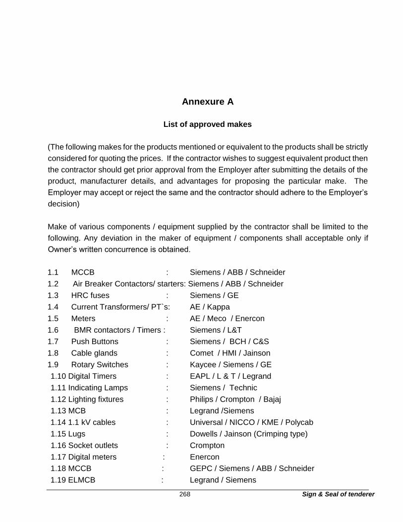
268 Sign & Seal of tenderer
Annexure A
List of approved makes
(The following makes for the products mentioned or equivalent to the products shall be strictly
considered for quoting the prices. If the contractor wishes to suggest equivalent product then
the contractor should get prior approval from the Employer after submitting the details of the
product, manufacturer details, and advantages for proposing the particular make. The
Employer may accept or reject the same and the contractor should adhere to the Employer’s
decision)
Make of various components / equipment supplied by the contractor shall be limited to the
following. Any deviation in the maker of equipment / components shall acceptable only if
Owner’s written concurrence is obtained.
1.1 MCCB : Siemens / ABB / Schneider
1.2 Air Breaker Contactors/ starters: Siemens / ABB / Schneider
1.3 HRC fuses : Siemens / GE
1.4 Current Transformers/ PT`s: AE / Kappa
1.5 Meters : AE / Meco / Enercon
1.6 BMR contactors / Timers : Siemens / L&T
1.7 Push Buttons : Siemens / BCH / C&S
1.8 Cable glands : Comet / HMI / Jainson
1.9 Rotary Switches : Kaycee / Siemens / GE
1.10 Digital Timers : EAPL / L & T / Legrand
1.11 Indicating Lamps : Siemens / Technic
1.12 Lighting fixtures : Philips / Crompton / Bajaj
1.13 MCB : Legrand /Siemens
1.14 1.1 kV cables : Universal / NICCO / KME / Polycab
1.15 Lugs : Dowells / Jainson (Crimping type)
1.16 Socket outlets : Crompton
1.17 Digital meters : Enercon
1.18 MCCB : GEPC / Siemens / ABB / Schneider
1.19 ELMCB : Legrand / Siemens

269 Sign & Seal of tenderer
1.20 Control fuses : GEPC
1.21 Capacitors : Siemens (EPCOS)/ L&T / MALDE
1.22 Panel fabricator : with prior approval of Owner / Consultant
1.23 PVC Copper wires : Finolex / Polycab / RR Cables / KEM
1.24 PVC Conduits : Precision / Shakti


![Technical Specification - University Services | · Web view[System/Application Name] Technical Design Specification Technical Design Specification Template Guideline To aid in the](https://img.pdfslide.us/doc/110x75/5ae76c407f8b9a08778e4f9f/technical-specification-university-services-viewsystemapplication-name-technical.jpg)