Embed Size (px)
Citation preview
PART-II - 1 -
Seal & Signature
of Bidder
GUJARAT ENERGY TRANSMISSION CORPORATION LTD.
Sardar Patel Vidyut Bhavan, Race Course,
Vadodara: 390 007
TECHNICAL SPECIFICATION
FOR
ERECTION WORK
OF
220 KV TRANSMISSION LINES
PART-II - 2 -
Seal & Signature
of Bidder
INDEX
Sr No
DESCRIPTION PAGE NO
1 SECTION-I
3
TECHNICAL SPECIFICATION
2 SECTION-II
EXECUTION OF WORK
11
3 SECTION-III
TECHNICAL DETAILS FOR ERECTION & COMMISSIONING OF TRANSMISSION LINE
21
PART-II - 3 -
Seal & Signature
of Bidder
INDEX SECTION- I
TECHNICAL SPECIFICATIONS 1. General Information and Scope 1.1 Scope 1.1.1 The work of erection & commissioning of 220kV transmission lines are included inthe scope of the Contractor. 1.1.2 Check survey of the route given by GETCO and preparation of profiles. 1.2 All types of 220 KV M/C & D/CTransmission tower materials suitable for “ACSR Zebra conductor as per the GETCO’s approved design/ drawing including approved quality bolt nuts ( 5.6 class), pack washers, spring washer will be supplied by GETCO & phase plate, number plate, circuit identification plate, anti climbing devices etc are in the scope of Contractor, however same shall be as per GETCO specification and approved drawings. 1.3 Procurement and supply of earthing material for pipe type and counter poise type earthing as per the GETCO’s approved drawing/s including all materials are in the scope of contractor. 1.4 Procurement and supply of danger plate, number plate, circuit identification plate and phase plate as per the GETCO’s approved drawings including all material and obstruction lights (wherever applicable) for aviation requirements (as required) are in the scope of contractor. 1.5 ACSR Zebra conductor, Earth wire 7/3.15mm, hardware & accessories for conductor and earth wire, 11KV Plain Disc Insulators/AF/SRI suitable for 220 KV ( suspension & Tension type ) will be supplied by GETCO. 1.6 Taking delivery of all materials from GETCO store by the successful contractor, to check the material before transportation from GETCO store to own works and to keep them in safe custody at t site store. 1.7 Transportation of all materials to erection site and transit insurance of material to be supplied / transported. 1.8 Excavation for different types of foundations of various towers as per GETCO approved drawing and back filling with normal soil, erection of tower,tack welding of bolt-nuts including supply and application of zinc rich primer and 2 coat of enamel paints for bottom most two panel ( up to 10Meter ) including special tower. 1.9 Insulator hoisting, stringing of conductor and earth wire including laying, jointing, jumpering and tree cutting of entire section for safe clearance. GETCO will be responsible for clearance towards right of way. 1.10 Guarantee of all above items, materials and activities. Other items not specifically mentioned in this Specification and are required for the successful erection and commissioning of the transmission line, unless specifically excluded in the Specification. 1.11 The successful Contractor has to carry out the design work for extension above 6 Mtr. to suit the approved tower design of GETCO including the design of their foundations and design of special Towers(River crossing) with no extra cost to GETCO.
PART-II - 4 -
Seal & Signature
of Bidder
2. Procurement of equipment, tools-tackles & materials: 2.1 All the materials, tools, equipments required in sufficient quantity, shall be procured/ arranged by the successful contractor before the work is taken up on hand and shall not link the delivery/completion period with non procurement/arrangement made by him for these items. 3 Drawings & Bills of Materials: 3.1 The GETCO shall provide one set of drawings and Bills of Material for various types of 220 KV D/C towers suitable for “ACSR Zebra” conductor upto 6 Mtr. extension to be utilized for this line to the successful contractor on award of contract. 3.2 The GETCO shall provide one set of detailed drawing to the successful contractor for various material like accessories, danger board & number plates to be procured by the Contractor. 3.3 The GETCO will provide drawings for foundation upto 6 Mtr. extension of towers and earthing to be carried out for various types of towers to the successful Contractor. 3.4 Design /drawing for any other item to be executed including foundation, tower, extension above 6 Mtr., additional member for special tower cross arm, special Tower (river crossing) , base plate assembly if any shall be prepared by the Contractor and submitted to the GETCO for approval at no extra cost to the GETCO. 6.0 Wastages:
6.1 No wastages are permitted for tower material, conductor, earth wire, 11KV Plain/AF Disc/SR insulators, hardware for conductor and earth wire, cement, RCC etc and shall make his own arrangement for storage to avoid breakage, losses and wastage of material, cement, etc. 6.2 The maximum ceiling for wastages permitted is as under:
Sr. No. Item % wastages permitted (Maximum) i) Conductor and Earth wire. ½% (for sag, jumper & sister Wire) 6.3 No wastage is allowed for any material except the percentage limit mentioned for Conductor & Earth wire here in above in Clause No. 6.2 7.0 Quantities: 7.1. The quantities mentioned in the schedule attached herewith are tentative and to be executed by the successful Contractor at the same rates accepted by the GETCO in the A/T and all the terms and conditions of an order. However, payment shall be made only for the quantities utilized / actual executed to complete the work. In case of any deviation resulting in any increase in quantity, prior approval of corporate office, GETCO will be required. 7.2 Templates for each type of 220 KV D/C towers suitable for “ACSR Zebra” conductor upto 6 Mtr. Extension will be provided by GETCO. 8. General:
PART-II - 5 -
Seal & Signature
of Bidder
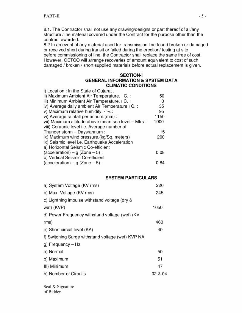
8.1. The Contractor shall not use any drawing/designs or part thereof of all/any structure /line material covered under the Contract for the purpose other than the contract awarded. 8.2 In an event of any material used for transmission line found broken or damaged or received short during transit or failed during the erection/ testing at site before commissioning of line, the Contractor shall replace the same free of cost. However, GETCO will arrange recoveries of amount equivalent to cost of such damaged / broken / short supplied materials before actual replacement is given.
SECTION-I GENERAL INFORMATION & SYSTEM DATA
CLIMATIC CONDITIONS
i) Location : In the State of Gujarat . ii) Maximum Ambient Air Temperature. ı C. : 50 iii) Minimum Ambient Air Temperature. ı C. : 0 iv) Average daily ambient Air Temperature ı C. : 35 v) Maximum relative humidity. - % : 95 vi) Average rainfall per annum.(mm) : 1150 vii) Maximum altitude above mean sea level – Mtrs : 1000 viii) Ceraunic level i.e. Average number of Thunder storm – Days/annum : 15 ix) Maximum wind pressure.(kg/Sq. meters) 200 ix) Seismic level i.e. Earthquake Acceleration a) Horizontal Seismic Co-efficient (acceleration) – g (Zone – 5) : 0.08 b) Vertical Seismic Co-efficient (acceleration) – g (Zone – 5) : 0.84
SYSTEM PARTICULARS
a) System Voltage (KV rms) 220
b) Max. Voltage (KV rms) 245
c) Lightning impulse withstand voltage (dry &
wet) (KVP) 1050
d) Power Frequency withstand voltage (wet) (KV
rms) 460
e) Short circuit level (KA) 40
f) Switching Surge withstand voltage (wet) KVP NA
g) Frequency – Hz
a) Normal 50
b) Maximum 51
III) Minimum 47
h) Number of Circuits 02 & 04
PART-II - 6 -
Seal & Signature
of Bidder
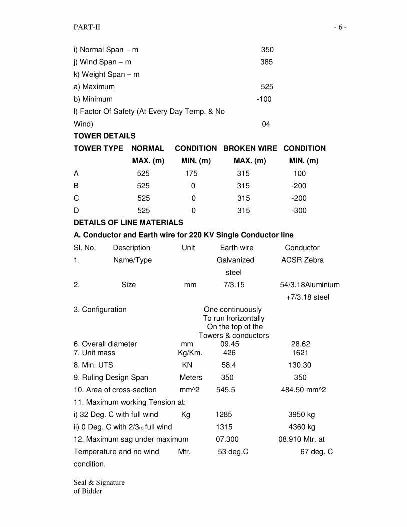
i) Normal Span – m 350
j) Wind Span – m 385
k) Weight Span – m
a) Maximum 525
b) Minimum -100
l) Factor Of Safety (At Every Day Temp. & No
Wind) 04
TOWER DETAILS
TOWER TYPE NORMAL CONDITION BROKEN WIRE CONDITION
MAX. (m) MIN. (m) MAX. (m) MIN. (m)
A 525 175 315 100
B 525 0 315 -200
C 525 0 315 -200
D 525 0 315 -300
DETAILS OF LINE MATERIALS
A. Conductor and Earth wire for 220 KV Single Conductor line
Sl. No. Description Unit Earth wire Conductor
1. Name/Type Galvanized ACSR Zebra
steel
2. Size mm 7/3.15 54/3.18Aluminium
+7/3.18 steel
3. Configuration One continuously To run horizontally On the top of the Towers & conductors 6. Overall diameter mm 09.45 28.62 7. Unit mass Kg/Km. 426 1621
8. Min. UTS KN 58.4 130.30
9. Ruling Design Span Meters 350 350
10. Area of cross-section mm^2 545.5 484.50 mm^2
11. Maximum working Tension at:
i) 32 Deg. C with full wind Kg 1285 3950 kg
ii) 0 Deg. C with 2/3rd full wind 1315 4360 kg
12. Maximum sag under maximum 07.300 08.910 Mtr. at
Temperature and no wind Mtr. 53 deg.C 67 deg. C
condition.
PART-II - 7 -
Seal & Signature
of Bidder
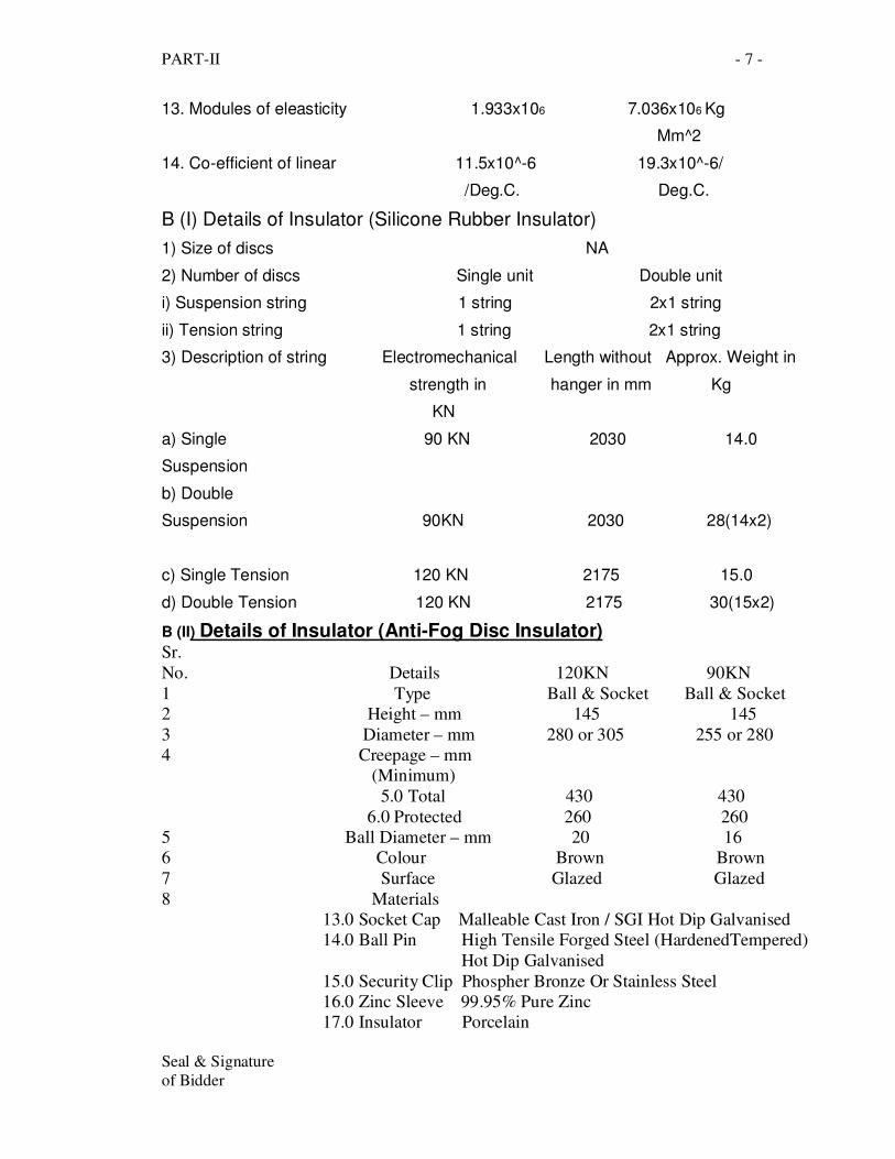
13. Modules of eleasticity 1.933x10⁶ 7.036x10⁶ Kg
Mm^2
14. Co-efficient of linear 11.5x10^-6 19.3x10^-6/
/Deg.C. Deg.C.
B (I) Details of Insulator (Silicone Rubber Insulator)
1) Size of discs NA
2) Number of discs Single unit Double unit
i) Suspension string 1 string 2x1 string
ii) Tension string 1 string 2x1 string
3) Description of string Electromechanical Length without Approx. Weight in
strength in hanger in mm Kg
KN
a) Single 90 KN 2030 14.0
Suspension
b) Double
Suspension 90KN 2030 28(14x2)
c) Single Tension 120 KN 2175 15.0
d) Double Tension 120 KN 2175 30(15x2)
B (II) Details of Insulator (Anti-Fog Disc Insulator) Sr.
No. Details 120KN 90KN
1 Type Ball & Socket Ball & Socket
2 Height – mm 145 145
3 Diameter – mm 280 or 305 255 or 280
4 Creepage – mm
(Minimum)
5.0 Total 430 430
6.0 Protected 260 260
5 Ball Diameter – mm 20 16
6 Colour Brown Brown
7 Surface Glazed Glazed
8 Materials
13.0 Socket Cap Malleable Cast Iron / SGI Hot Dip Galvanised
14.0 Ball Pin High Tensile Forged Steel (HardenedTempered)
Hot Dip Galvanised
15.0 Security Clip Phospher Bronze Or Stainless Steel
16.0 Zinc Sleeve 99.95% Pure Zinc
17.0 Insulator Porcelain
PART-II - 8 -
Seal & Signature
of Bidder
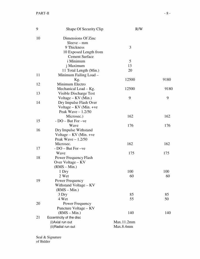
9 Shape Of Security Clip R/W
10 Dimensions Of Zinc
Sleeve – mm
9 Thickness 3
10 Exposed Length from
Cement Surface
i Minimum 5
j Maximum 13
11 Total Length (Min.) 20
11 Minimum Failing Load –
Kg. 12500 9180
12 Minimum Electro
Mechanical Load – Kg. 12500 9180
13 Visible Discharge Test
Voltage – KV (Min.) 9 9
14 Dry Impulse Flash Over
Voltage – KV (Min. +ve
Peak Wave – 1.2/50
Microsec.) 162 162
15 - DO – But For –ve
Wave 176 176
16 Dry Impulse Withstand
Voltage – KV (Min. +ve
Peak Wave – 1.2/50
Microsec. 162 162
17 - DO – But For –ve
Wave 175 175
18 Power Frequency Flash
Over Voltage – KV
(RMS – Min.)
1 Dry 100 100
2 Wet 60 60
19 Power Frequency
Withstand Voltage – KV
(RMS – Min.)
3 Dry 85 85
4 Wet 55 50
20 Power Frequency
Puncture Voltage – KV
(RMS – Min.) 140 140
21 Eccentricity of the disc
(i)Axial run out Max.11.2mm
(ii)Radial run out Max.8.4mm
PART-II - 9 -
Seal & Signature
of Bidder
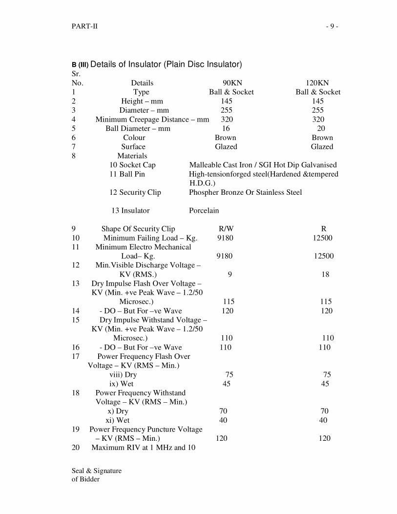
B (III) Details of Insulator (Plain Disc Insulator) Sr.
No. Details 90KN 120KN
1 Type Ball & Socket Ball & Socket
2 Height – mm 145 145
3 Diameter – mm 255 255
4 Minimum Creepage Distance – mm 320 320
5 Ball Diameter – mm 16 20
6 Colour Brown Brown
7 Surface Glazed Glazed
8 Materials
10 Socket Cap Malleable Cast Iron / SGI Hot Dip Galvanised
11 Ball Pin High-tensionforged steel(Hardened &tempered
H.D.G.)
12 Security Clip Phospher Bronze Or Stainless Steel
13 Insulator Porcelain
9 Shape Of Security Clip R/W R
10 Minimum Failing Load – Kg. 9180 12500
11 Minimum Electro Mechanical
Load– Kg. 9180 12500
12 Min.Visible Discharge Voltage –
KV (RMS.) 9 18
13 Dry Impulse Flash Over Voltage –
KV (Min. +ve Peak Wave – 1.2/50
Microsec.) 115 115
14 - DO – But For –ve Wave 120 120
15 Dry Impulse Withstand Voltage –
KV (Min. +ve Peak Wave – 1.2/50
Microsec.) 110 110
16 - DO – But For –ve Wave 110 110
17 Power Frequency Flash Over
Voltage – KV (RMS – Min.)
viii) Dry 75 75
ix) Wet 45 45
18 Power Frequency Withstand
Voltage – KV (RMS – Min.)
x) Dry 70 70
xi) Wet 40 40
19 Power Frequency Puncture Voltage
– KV (RMS – Min.) 120 120
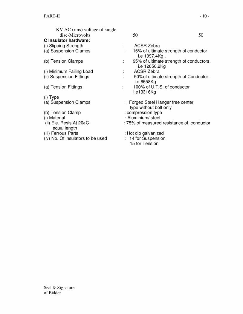
20 Maximum RIV at 1 MHz and 10
PART-II - 10 -
Seal & Signature
of Bidder
KV AC (rms) voltage of single
disc-Microvolts 50 50 C Insulator hardware: (i) Slipping Strength : ACSR Zebra (a) Suspension Clamps : 15% of ultimate strength of conductor i.e 1997.4Kg . (b) Tension Clamps : 95% of ultimate strength of conductors. i.e 12650.2Kg (i) Minimum Failing Load : ACSR Zebra (ii) Suspension Fittings : 50%of ultimate strength of Conductor . i.e 6658Kg (a) Tension Fittings : 100% of U.T.S. of conductor i.e13316Kg (i) Type (a) Suspension Clamps : Forged Steel Hanger free center type without bolt only (b) Tension Clamp : compression type (i) Material : Aluminium/ steel (ii) Ele. Resis.At 200 C : 75% of measured resistance of conductor equal length (iii) Ferrous Parts : Hot dip galvanized (iv) No. Of insulators to be used : 14 for Suspension 15 for Tension
PART-II - 11 -
Seal & Signature
of Bidder
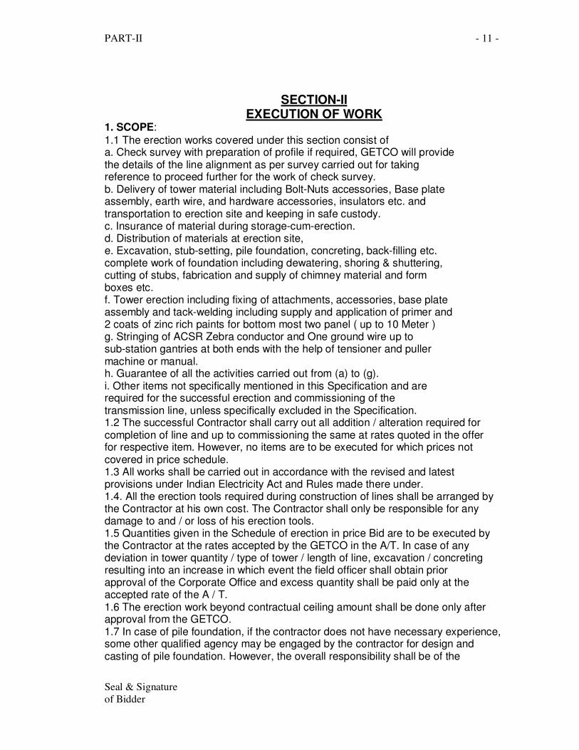
SECTION-II EXECUTION OF WORK
1. SCOPE:
1.1 The erection works covered under this section consist of a. Check survey with preparation of profile if required, GETCO will provide the details of the line alignment as per survey carried out for taking reference to proceed further for the work of check survey. b. Delivery of tower material including Bolt-Nuts accessories, Base plate assembly, earth wire, and hardware accessories, insulators etc. and transportation to erection site and keeping in safe custody. c. Insurance of material during storage-cum-erection. d. Distribution of materials at erection site, e. Excavation, stub-setting, pile foundation, concreting, back-filling etc. complete work of foundation including dewatering, shoring & shuttering, cutting of stubs, fabrication and supply of chimney material and form boxes etc. f. Tower erection including fixing of attachments, accessories, base plate assembly and tack-welding including supply and application of primer and 2 coats of zinc rich paints for bottom most two panel ( up to 10 Meter ) g. Stringing of ACSR Zebra conductor and One ground wire up to sub-station gantries at both ends with the help of tensioner and puller machine or manual. h. Guarantee of all the activities carried out from (a) to (g). i. Other items not specifically mentioned in this Specification and are required for the successful erection and commissioning of the transmission line, unless specifically excluded in the Specification. 1.2 The successful Contractor shall carry out all addition / alteration required for completion of line and up to commissioning the same at rates quoted in the offer for respective item. However, no items are to be executed for which prices not covered in price schedule. 1.3 All works shall be carried out in accordance with the revised and latest provisions under Indian Electricity Act and Rules made there under. 1.4. All the erection tools required during construction of lines shall be arranged by the Contractor at his own cost. The Contractor shall only be responsible for any damage to and / or loss of his erection tools. 1.5 Quantities given in the Schedule of erection in price Bid are to be executed by the Contractor at the rates accepted by the GETCO in the A/T. In case of any deviation in tower quantity / type of tower / length of line, excavation / concreting resulting into an increase in which event the field officer shall obtain prior approval of the Corporate Office and excess quantity shall be paid only at the accepted rate of the A / T. 1.6 The erection work beyond contractual ceiling amount shall be done only after approval from the GETCO. 1.7 In case of pile foundation, if the contractor does not have necessary experience, some other qualified agency may be engaged by the contractor for design and casting of pile foundation. However, the overall responsibility shall be of the
PART-II - 12 -
Seal & Signature
of Bidder
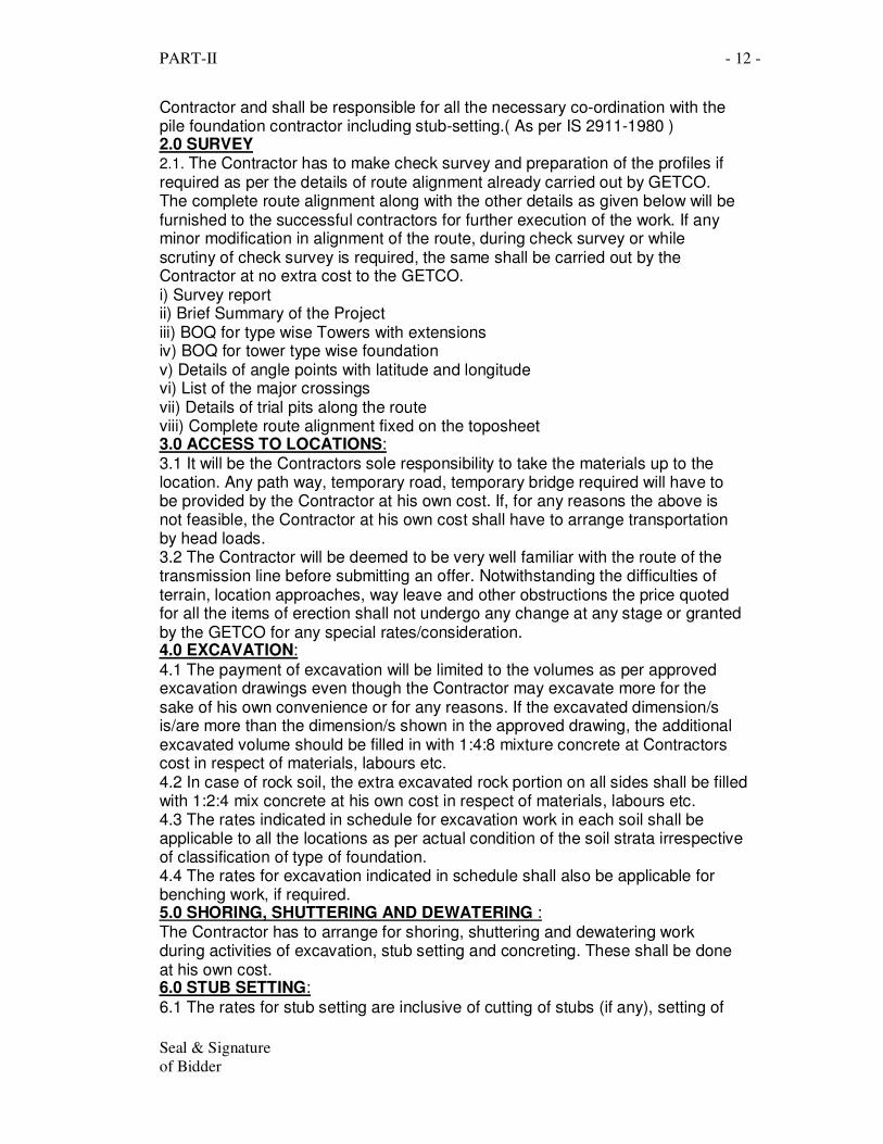
Contractor and shall be responsible for all the necessary co-ordination with the pile foundation contractor including stub-setting.( As per IS 2911-1980 ) 2.0 SURVEY 2.1. The Contractor has to make check survey and preparation of the profiles if required as per the details of route alignment already carried out by GETCO. The complete route alignment along with the other details as given below will be furnished to the successful contractors for further execution of the work. If any minor modification in alignment of the route, during check survey or while scrutiny of check survey is required, the same shall be carried out by the Contractor at no extra cost to the GETCO. i) Survey report ii) Brief Summary of the Project iii) BOQ for type wise Towers with extensions iv) BOQ for tower type wise foundation v) Details of angle points with latitude and longitude vi) List of the major crossings vii) Details of trial pits along the route viii) Complete route alignment fixed on the toposheet 3.0 ACCESS TO LOCATIONS: 3.1 It will be the Contractors sole responsibility to take the materials up to the location. Any path way, temporary road, temporary bridge required will have to be provided by the Contractor at his own cost. If, for any reasons the above is not feasible, the Contractor at his own cost shall have to arrange transportation by head loads. 3.2 The Contractor will be deemed to be very well familiar with the route of the transmission line before submitting an offer. Notwithstanding the difficulties of terrain, location approaches, way leave and other obstructions the price quoted for all the items of erection shall not undergo any change at any stage or granted by the GETCO for any special rates/consideration. 4.0 EXCAVATION:
4.1 The payment of excavation will be limited to the volumes as per approved excavation drawings even though the Contractor may excavate more for the sake of his own convenience or for any reasons. If the excavated dimension/s is/are more than the dimension/s shown in the approved drawing, the additional excavated volume should be filled in with 1:4:8 mixture concrete at Contractors cost in respect of materials, labours etc. 4.2 In case of rock soil, the extra excavated rock portion on all sides shall be filled with 1:2:4 mix concrete at his own cost in respect of materials, labours etc. 4.3 The rates indicated in schedule for excavation work in each soil shall be applicable to all the locations as per actual condition of the soil strata irrespective of classification of type of foundation. 4.4 The rates for excavation indicated in schedule shall also be applicable for benching work, if required. 5.0 SHORING, SHUTTERING AND DEWATERING : The Contractor has to arrange for shoring, shuttering and dewatering work during activities of excavation, stub setting and concreting. These shall be done at his own cost. 6.0 STUB SETTING:
6.1 The rates for stub setting are inclusive of cutting of stubs (if any), setting of
PART-II - 13 -
Seal & Signature
of Bidder
stubs, leveling at correct level, dismantling of template after concrete, back-filling work etc. 6.2. Above rates shall be on per MT basis for normal, extensions up to 21 meters and special/river crossing towers. 6.3. The weights payable for stub-setting item shall comprise of the weight of stub and its respective stub setting template as per approved bill of material. 7.0 CONCRETE: 7.1. The rates indicated in schedule for concrete work shall be applicable to all the locations irrespective of soil strata and type of foundation adopted. The Contractor shall have to procure cement from the open market according to line requirement and keep sufficient quantities to avoid delay in work. Account of cement utilized at each location duly certified by concerned GETCO supervisor and engineer in charge of work, is required to be maintained and submitted with each R.A Bill. No wastage is permitted as same is to be procured by the Contractor of brand approved by the GETCO at his own cost from the authorized dealer. 7.2 Use of Cement : The rates in Schedule-‘B’ are inclusive of cement cost. Contractor has to purchase fresh 43 grade cement confirming to IS 8112 and brand approved by GETCO. Contractor has to construct pucca godown at site of work so that cement bags can be properly preserved to avoid damage due to any kind of water and moisture. Contractor has to bring sufficient quantities of cement bags and at no time less then 200 (Two hundred) bags to maintain progress of work. The work should not suffer for want of cement. It is full responsibility of Contractor to bring sufficient cement at site at right time. Cement should give the required strength of cement concrete. Contractor has to submit material account for consumption of cement used with every bill. In case of non submission of the same, bill will not be passed. Contractor has to submit the copy of cement purchased bill along with each RA Bill/Final Bill. Nothing will be paid extra for over consumption. Contractor is fully responsible for safety of cement at site. If GETCO authorized representative desires to check cement stock at site, Contractor has to allow him at any time. Contractor has to maintain day to day cement consumption/balance account at site. As far as possible, Contractor has to maintain supply of cement of only one brand & grade through out the work and on account of closer/shortage of approved brand, cement of other brand in accordance of condition no. (1) will be allowed by Engineer-In-Charge. Minimum cement consumption considered for nominal mix cement concrete will be as follows:- a. 1:1.5:3 - 8.12 Bags per CMT b. 1:2:4 - 6.5 Bags per CMT c. 1:3:6 - 4.5 Bags per CMT d. 1:4:8 - 3.5 Bags per CMT In respect of pile foundation, GETCO reserves the right to adopt design mix and same will be indicated in BOQ of bidding document. Contractor has to use minimum cement as above. Contractor should not use less than the prescribed quantities of cement. Contractor will be allowed to carry out work only after physical verification of cement available at site .
PART-II - 14 -
Seal & Signature
of Bidder
7.3 The GETCO reserves the right to test the quality of steel and cement procured by the Contractor at any Government recognized laboratory and the test results shall be binding to the Contractor. If the test results are not found satisfactory the entire lot supplied and work executed has to be replaced / re-executed by the Contractor at no extra cost to the GETCO. 7.4 Back filling of the excavated soil is to be arranged by the successful contractor. For back filling if borrowed earth is required, the same should be arranged of good quality and quantity irrespective of site condition at no extra cost to the GETCO. 7.5 The sand shall be of the best quality containing hard siliceous materials, clean and of sharp angular grit type and free from earth or organic matter or salts and to the satisfaction of the Engineer in-charge. The sand shall be washed before use. No saltiest or brackish water shall be used for concreting. 7.6 The mixture of concrete to be used shall be such as to produce a sound, compact and water-proof concrete. The mixture shall not be weaker than the ratio to be prepared. The concrete for chimney shall be prepared with 20 mm stone metal and the concrete for pyramid/step/pad shall be prepared with 20 mm or 40 mm stone metal. The mixture shall be prepared using mixing machine only. It should also be free from grit and dirt. The concrete shall be mixed as stiff as required for placing the concrete in the form of moulds with ease and degree to which concrete resists segregation will permit. Hence, the quantity of water used should not be too much. 7.7 Proper form boxes or moulds adequately braced to retain proper shape while concreting should be used for chimney, pyramid and slab portions & vibrator machine shall be used at the time of concreting. Form boxes should be water tight so as not to allow cement cream to come out leaving only sand and gully to form honey combs in concrete. Form boxes should be cleaned and oiled before using for concreting. 7.8 All sub-merged locations must be kept completely dewatered both during the placing of concrete and for 24 hours after completion. There should be no disturbance of concrete by water during this period. 7.9 Form boxes should not be removed before 24 hours, after concreting. Concrete surfaces where required should be set right with rich cement and mortar after removal of the forms. 7.10 The Chief Engineer (Projects) or Engineer appointed by him at his sole discretion may uncover any cast foundation to find out the workmanship of foundation. Contractor shall render necessary assistance during such fact finding operation and shall comply the report of the investigating officer. 7.11 The Contractor will be responsible for constructing the foundations in accordance with the design of each type of foundation supplied by the GETCO. 7.12 The payment of excavation will be limited to the volumes as per approved excavation drawings even though the Contractor may excavate more for the sake of his own convenience or for any reasons. If the excavated dimension/s is/are more than the dimension/s shown In the approved drawing, the additional excavated volume should be filled in with 1:4:8 mixture concrete at Contractors cost in respect of materials, labours etc. 7.13 In case of rock soil, the extra excavated rock portion on all sides shall be filled with M20 mix concrete at his own cost in respect of materials, labours etc. 7.14 The rates for excavation indicated in schedule shall also be applicable for
PART-II - 15 -
Seal & Signature
of Bidder
benching work, if required.: PART- II
7.15 The tor / plain steel bars required for RCC type foundation shall be procured by the successful Contractor in advance to avoid delay in the work. 7.16 No wastage is permitted for reinforcement steel, as the same is to be procured by the Contractor at his own cost. No over lapping of RCC is permitted in foundation work. 7.17 GETCO reserves right to test the quality of steel and cement procured by the Contractor at any Govt. recognized Laboratory and intended to be used for the tower foundation works. The test results shall be binding to the Contractor and GETCO. 8.0 Classification of Soil. a) Normal Dry Soil: The soil readily removable with ordinary spades and shovels viz. Murram, hard murram etc. and to be used for location in normal dry cohesive or non cohesive soils. If the black cotton soil is encountered up to 500 mm below ground level, normal dry soil foundation shall have to be adopted.(The normal dry soil foundation designs shall be inclusive of this stipulation) b) Sandy dry soil: To be used for locations where cohesion less pure sand or negligible cohesive sand mixed with soil are met in dry condition c) Sandy wet soil: To be used in location where water table is met from top d) Fully submerged black cotton Soil.
To be used at locations where soil is clay type, not necessarily black in color, which shrinks when dry and swells when wet, resulting in differential movement extending to a max., depth of 3.5 meter below ground level. For designing foundation for this location the soil is to be considered submerged in nature. If the black cotton soil is encountered only up to 500 mm from ground level, normal dry soil foundation shall be adopted. (This foundation design shall be inclusive of this stipulation). e) Soft Rock: To be used at locations where decomposed or fissured rock, hard gravel, kankar, lime stone, laterite or any other soil of similar nature is met. Undercut type foundation is to be used for soft rock locations. f) Hard Rock To be used at locations where chiseling, drilling, and blasting is required. g) Fully submerged soil: To be used at locations where sub soil water table is met at less than 1.50 meter below ground level and up to complete depth of foundation. h) Partially submerged soil: To be used at the locations where the submerged soil water table is met at 1.5m or more than 1.5 m below the ground level, the top
PART-II - 16 -
Seal & Signature
of Bidder
portion of the strata being normal dry soil. Soil strata for adopting various types of foundations: 9.0 Curing and back-filling : 9.1 After 24 hours of pouring, the concrete should be cured by keeping it continuously wet for 14 days. After 48 hours of pouring, the pit may be backfilled with excavated selected earth (which is free from grass, dung, wooden waste, postures and fodder woods, shrubs, thorn etc.) sprinkled with necessary amount of water and well compressed and consolidated in layers not exceeding 150 mm. If the excavated soil consists of large boulders/stone, the same shall be broken to maximum size 80 mm and mixed with soil to be back filled. At the locations where borrowed earth is required for back filling, this shall be done by the Contractor at his own cost, irrespective of transportation from any land. Thereafter, the exposed top end fill shall be kept wet for the remainder of above prescribed curing period. The uncovered portion of concrete chimney above the back filled earth shall be kept wet by providing empty gunny bags fully wrapped around the concrete chimney for curing and ensure that the bags are kept wet by frequent pouring of water on them. 9.2 Extra ordinary care shall be taken during back filling. The Contractor and GETCO Engineer at site shall ensure that the back filling is done in the manner referred above so that back-filled earth become homogeneous with surrounding parent soil with the passage of time. The record for the same with day/date of curing, back filling etc be maintained in the register and duly signed by the Contractor and GETCO representative. The quantities of excavated earth obtained from a particular location shall be generally utilized in back filling work in protection of tower footing of same location unless it is unsuitable for such purpose. In the later case, the back filling shall be done with borrowed earth of suitable quality irrespective of land and the consolidation of earth shall also be done free of cost. 9.3 The rates of stub setting are including the work of back filling of excavated pit. The large stones / boulders shall be broken to maximum 80 mm size before used for back-filling at no extra cost to the GETCO. 10.0 PROTECTION OF TOWER FOOTING : Quantities of various protection works like stone revetment, concrete revetment, brick masonry and random stone masonry to the foundations are to be executed by the successful Contractor if indicated in the schedule and payment for such quantity shall be as per unit rates accepted. 11.0 TOWER ERECTION AND GROUNDING: ( a ) ERECTION OF TOWERS: 11.1 The super-structure of towers should be erected on foundations after 14 days of concreting. However, the method adopted for erection of tower is left to the discretion of the Contractor subject to the condition that he takes responsibility for any damage to materials. No tower member should get strained or bent during erection. The towers must be truly vertical after erection and no straining would be allowed to bring it in alignment. Maximum tolerance in verticality that will be permitted is ONE mm per 360mm of tower height. The bolt head shall be on outside faces and nuts and washers on
PART-II - 17 -
Seal & Signature
of Bidder
inside faces of the tower. All bolts & nuts shall be made fully tight and finally the bolt threads shall be centre punched to avoid nuts getting loose. Punching of bolts shall be made by chamfering the threads with centre punch at least at three places equally spaced on contact surface of bolts and nuts. 11.2 Complete tower erection shall include erection of all accessories like danger board, number plate, phase plate, C.I. Plate, Anti-climbing devices and fittings including attachments like step bolts, ladders, platforms, 'U' bolts, shackles, hangers, strain plates etc. 11.3 Suitable tower extension shall be erected to get desired ground clearance whenever required, as determined at the time of survey and profiles. 11.4 To avoid pilferage of bolts and nuts and tower members, the bolts of the two bottoms most panels (up to 10 meters) shall be tack welded at three places on the nuts diametrically. The zinc rich paint shall be procured by the Contractor at his own cost and shall be applied immediately following the tack welding. 11.5 The Contractor shall measure the tower footing resistance of each tower after it has been erected and before stringing of the earth wire during dry weather. Each tower shall be earthed; the tower footing resistance shall not exceed 10 ohms. Pipe type and counter poise type earthing which ever required shall be done in accordance with the latest edition and revision of IS : 3043 ( code of practice for earthing ).The Contractor shall measure the footing resistance of each location and prepare the record for submission and approval of Engineer-in-Charge for deciding the type of grounding to be provided. 11.6 Pipe Type Earthing : At locations where footing resistance does not exceed 10 Ohms., the pipe type earthing as per appended drawing shall be provided. The Contractor will have to supply all the materials required for grounding like pipe, flat, boltnuts, salt, fine broken coke/charcoal etc. The earthing is to be done by making a bore hole for insertion of pipe away from the tower leg excavation line as per attached drawings. 11.7 Counterpoise Earthing : At locations, where footing resistance exceeds 10 Ohms, counterpoise earthing as per appended drawing shall be provided to bring down the tower footing resistance below 10 Ohms. The Contractor will have to supply all the materials required for grounding like lugs, G.I. wire, bolts, nuts etc. The counterpoise earthing shall be buried 1000 mm below ground level. 11.8 The method for providing earthing shall be at the desecration of the Contractor. 11.9 The rates for erection of structure of tower and extension up to 21 meters and special / river crossing tower on special foundation/pile foundation carried out by Contractor shall be on per MT basis. These rates shall be valid irrespective of location, nature and specification. 11.10 The payment for superstructure / extension / special or river crossing tower shall be made only after erection of complete tower as per structural drawing. 11.11 The rates for fixing of anti-climbing devices, danger board, number plate, phase plate, circuit identification plate shall be inclusive of all materials and
PART-II - 18 -
Seal & Signature
of Bidder
labour. 11.12 The rates for providing earthing to the tower either pipe or counter poise type inclusive of supply of complete earthing set, coke, charcoal, salt etc. including required bolt nuts as per approved drawing all materials and labour. 11.13 The Contractor shall arrange for all the equipments for tack-welding purpose. The rates shall be inclusive of supply and application of zinc rich paint on it. 11.14 The Contractor shall arrange required equipments for measurement of soil and tower footing resistance of each location, the tower footing resistance shall be less than 10 Ohms and submit the joint measurement record of same jointly signed by Contractor and Engineer in charge of line with final bill. The payment shall be released only after receipt of final soil resistance details on providing earthing at each location. 12.0 INSULATOR HOISTING: 12.1 11KV Plain/AF Disc insulators/SRI shall be used on all tangent Towers and tension towers (small, medium & large angle). 13.0 STRINGING :- The stringing work should be carried with the help of tensioner and puller machine or Manual. 13.1 The rates for any type of stringing work, out of followings are indicated in Schedule. i) Stringing of one/two ground wire/s, ii) Stringing of single / double circuit line. iii) Hot-line stringing of conductor iv) LILO arrangement 13.2 The rates for stringing of conductors and ground wire for special crossings like river shall be on per KM basis only and shall be paid according to actual work done. In case special towers are suspension type, the special shall mean major river crossing section considering the span from one anchor tower to the other end anchor tower. If the special towers are tension type, the special crossing shall mean span from special tower to special tower of other end. 13.3 The stringing work should be planned in such a manner in consultation with the Engineer in charge of the work that minimum shut down of power line crossings are required. Revenue loss due to any undue shut down i.e. after the shut down is arranged and required to be extended on account of Contractor shall be recoverable from the Contractor. 13.4 Before commencing of stringing work, Contractor must obtain approval of sag tension charts (these shall have to be supplied by the Contractor) showing final sag and tension for various temperature and spans. The stringing chart shall be prepared according to appended format only. 13.5 The Contractor shall be responsible and will take care of proper handling of Conductor drums. Sufficient numbers of aluminum snatch blocks shall be used for paying out the ACSR Conductor. Necessary precautions shall be taken to avoid conductor rubbing on the ground by providing adequate ground roller, rollers on supports. Additional rollers shall also be provided to cross thorny hedges, footing and other obstructions to avoid scratching of conductor. The conductor and ground wire shall be made to sag correctly as
PART-II - 19 -
Seal & Signature
of Bidder
per stringing charts, before they are finally transferred to the hardwares for conductors and to clamps for ground wire. No joint should be made at less than 30 metres from the tower end and no joint shall be permitted in Railway, River, road and other important crossings spans. There shall not be more than one joint in a span of each conductor. The sag shall be adjusted to suit the sag indicated against actual temperature for an individual span. The thermometer shall be provided at the conductor point during the stringing work. Dynamometers shall be used in tensioning the conductors. All conductors shall be stressed to their maximum working load at the time of stringing, as per approved stringing charts. 13.6 The minimum clearance between the lowest point of conductor and ground shall not be less than required. All compression joints should be carefully made and a record of initial and final lengths of the joints jointly signed by Contractor's and GETCO representatives shall be maintained. Check for sag should also be made at intervals when conductors are drawn up. Over stressing, causing damage to towers, should be avoided. Care should be exercised not to over tension the conductor. An extra sag of 150 mm be allowed at all the important tension locations like Railway/River Crossings. For stringing of bundle conductor on line, the Contractor shall use only tension stringing equipment. The earth wire may be strung by conventional method and tension stringing equipments may not be used. The Contractor shall ensure that the stringing gadgets are not anchored to the tower footing. Each phase conductor shall consist of one conductor of size 54/3.18 mm. Al.+7/3.18 mm. steel - ACSR Zebra. the ground wire shall be 7/3.15mm galvanized steel wire. To avoid contact with the ground or any object above ground level the conductor shall be pulled by the controlled tension methods using neoprene lined double pulled wheel type tension stringing equipments. The equipments shall be capable continuous of maintaining continuous tension of not less than of 5000 kg. which shall be such that the conductor is maintained about 20% grater than the sags specified in the correspondence stringing sag tables. 13.7 After being pulled the conductor/ground wire shall not be allowed to hang in the stringing sheaves for more than 72 hours, before being pulled to the specified sag. During the time the conductor / ground wire is on the stringing sheaves before sagging-in, it shall be ensured that the conductor / ground wire is not damaged due to wind, vibration, vehicles or other causes. Scaffolding should be used to cross the important roads and Railway Crossing for minimum interruption to traffic. 13.8 The conductor shall be pulled up to desired sag and left in serial stringing sheaves for at least one hour after which the sag shall be rechecked and adjusted, if necessary, before clipping in and transferring the conductors from the serial stringing sheaves to the suspension clamps. 13.9 Conductor shall be clamped within 24 hours of sagging. The sag will be checked in the larger spans of the section in case of sections up to eight spans and in one intermediate larger span also for section with more than eight spans. 13.10 The stringing sheaves, when suspended on the transmission structure for sagging, shall be so adjusted that the conductor will be on the sheaves at the
PART-II - 20 -
Seal & Signature
of Bidder
same height as the suspension clamp to which it is to be secured. 13.11 The stringing of the ground wire shall be done in accordance with the stringing charts approved by the GETCO. The ground wire of galvanized steel shall be strung to run continuously over the conductors. The ground wire shall be pulled, sagged and clamped-in from tension tower to tension tower before the phase conductors are pulled in that section. 13.12 All the line conductors shall be terminated at sub-station structures whose details shall be furnished by the GETCO at the appropriate time. The contractor shall fix strain insulators on the sub-station structures. 13.13 Armour rods and vibration dampers shall be fitted at each suspension tower before final clamping of conductor with Insulator strings. Vibration damper shall be fitted at each tension tower after final clamping of conductor with insulator strings. Vibration dampers are to be fixed using aluminum tape with each clamping bolt and in correct vertical position in relation to conductor. Compression type joints are to be used for jointing of conductors. Each part connected with joints shall be perfectly cleaned by wire brush and properly greased before final compression. All the joints of conductors and earth wire shall be made with the best workmanship and shall be perfectly straight and having maximum possible strength. 13.14 Proper guys shall be provided to counter balance the paying out tension of conductor/ground wire at the tension locations, to avoid damage to towers and/or accident. 13.15 Stringing work shall mean, the activities of fixing of insulator and insulator hardwares, paying, jointing, tensioning, clamping with armour-rod, providing dampers, repairing of conductors (if any) and fixing the conductor at tension hardwares etc. 14.0 FIELD QUALITY PLAN
14.1 Contractor shall invariably submit the FQP along with Technical Bid for erection of line including all the activities such as excavation, concreting, erection, stringing etc. with detailed check list to be referred
PART-II - 21 -
Seal & Signature
of Bidder
SECTION- III TECHNICAL DETAILS FOR ERECTION &
COMMISSIONING OF TRANSMISSION LINE 1.0 SURVEY
survey & check survey :- The Contractor has to carry out check survey, profile using modern technique as per the complete BOQ given in this section. If any minor modification in alignment of route, during check survey or while scrutiny of check survey is required, the same shall be carried out by the Contractor at no extra cost to the GETCO. 2.0 TESTING AND COMMISSIONING: 2.1 The Contractor after completion of erection work will ensure that all works connected with line have been completed. These works shall be done correctly as per Indian Electricity Rules and Procedures. Any extra cost involved due to incompleteness of work or bad workmanship found out subsequently shall be set right forthwith by the Contractor at his own cost. 2.2 After the erection is complete in all respects, the line should be thoroughly patrolled and checked for continuity and clearances. The line should be meggered to check its insulation level. A written confirmation should be given to the Engineer-in-Charge that, the men, materials, tools and earthings (if any) are removed and the line is safe for charging. On charging the line, if it does not stand and trips, the Contractor should arrange to patrol the line and find out the causes of the tripping and rectify the defect at no extra cost to the GETCO. 3.0 HANDING OVER OF LINE DOCUMENTS:
3.1 On completion of all erection activities, the Contractor has to furnish following information along with technical details to concerned Engineer-in-Charge of the work in triplicate duly bound:- 1) Approved surveyed route with permanent marks, (To be obtained from the GETCO) 2) Approved copy of profiles with tower schedule, (To be obtained from the GETCO except for portion where any change is approved) 3) Location wise soil strata details of each pit excavated, type of foundation executed, volumes of excavation & concrete and RCC steel weights, 4) Details of revetment, retaining walls, etc., work done for protection of tower footing and their approved drawing copies, 5) Approved copies of excavation plan and foundation drawings, (To be obtained from the GETCO) PART- II
GETCO/E/TS EOL54/R0DT.07/07/2009 SEAL AND SIGNATURE
OF CONTRACTOR
26
6) Approved copies of structural drawings of stubs, templates, towers, extensions, etc., (To be obtained from the GETCO) 7) Approved copies of stringing charts,
PART-II - 22 -
Seal & Signature
of Bidder
8) Value of tower footing resistance jointly measured before & after providing earthing and type of earthing executed, duly signed by Engineer Incharge of line. 9) Details of spans and phase where mid span joint, repair sleeve are provided, 10) Location wise type and numbers of insulators, insulator hardwares, earth wire hardware, conductor accessories, provided, etc. 11) Separate detail of each crossing like road, river, railway, power line, etc and details of clearance as per Indian Electricity Rules. 4.0 GENERAL:
4.1 The Contractor shall ensure that at the end of each sub-activity the surplus material is immediately removed from the work-site to avoid loss and injury to the public. 4.2 The Contractor has to make reconciliation of material account and to settle final bill including signature in all relevant papers required for passing of final bill within three months from the date of charging / commissioning of line. 4.3 A lump sum amount of 6 % of the order value OR Rs.1.0 lac whichever is less, will be with held from the running bills of stringing work, which will be released only after handing over of these documents to the satisfaction of concerned Superintending. Engineer (Trans).