Embed Size (px)
Citation preview
Hkkjr ljdkj & jsy ea=ky; vuqla/kku vfHkdYi vkSj ekud laxBu
lR;eso t;rs
TECHNICAL SPECIFICATION FOR
DEVELOPMENT OF A LOCOMOTIVE DRIVE GEAR SYSTEM WITH FULLY SUSPENDED TRACTION MOTOR
FOR DIESEL LOCOMOTIVES
SPECIFICATION NO. MP-0.49.00.21 (Revision - 00)
May 2013
Government of India - Ministry of Railways Research Designs & Standards Organisation,
LUCKNOW – 226011
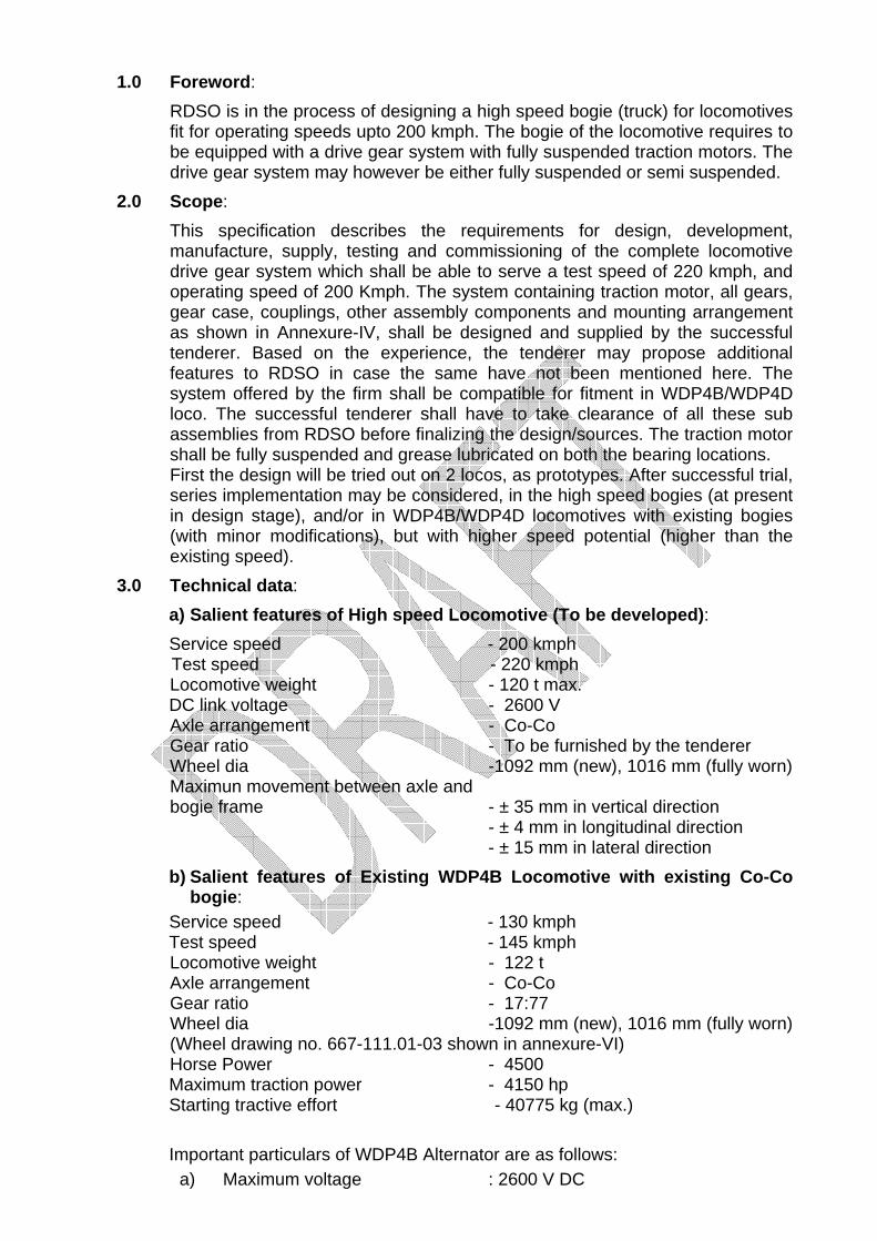
1.0 Foreword:
RDSO is in the process of designing a high speed bogie (truck) for locomotives fit for operating speeds upto 200 kmph. The bogie of the locomotive requires to be equipped with a drive gear system with fully suspended traction motors. The drive gear system may however be either fully suspended or semi suspended.
2.0 Scope: This specification describes the requirements for design, development,
manufacture, supply, testing and commissioning of the complete locomotive drive gear system which shall be able to serve a test speed of 220 kmph, and operating speed of 200 Kmph. The system containing traction motor, all gears, gear case, couplings, other assembly components and mounting arrangement as shown in Annexure-IV, shall be designed and supplied by the successful tenderer. Based on the experience, the tenderer may propose additional features to RDSO in case the same have not been mentioned here. The system offered by the firm shall be compatible for fitment in WDP4B/WDP4D loco. The successful tenderer shall have to take clearance of all these sub assemblies from RDSO before finalizing the design/sources. The traction motor shall be fully suspended and grease lubricated on both the bearing locations.
First the design will be tried out on 2 locos, as prototypes. After successful trial, series implementation may be considered, in the high speed bogies (at present in design stage), and/or in WDP4B/WDP4D locomotives with existing bogies (with minor modifications), but with higher speed potential (higher than the existing speed).
3.0 Technical data: a) Salient features of High speed Locomotive (To be developed): Service speed - 200 kmph Test speed - 220 kmph
Locomotive weight - 120 t max. DC link voltage - 2600 V
Axle arrangement - Co-Co Gear ratio - To be furnished by the tenderer Wheel dia -1092 mm (new), 1016 mm (fully worn) Maximun movement between axle and
bogie frame - ± 35 mm in vertical direction - ± 4 mm in longitudinal direction
- ± 15 mm in lateral direction b) Salient features of Existing WDP4B Locomotive with existing Co-Co
bogie: Service speed - 130 kmph Test speed - 145 kmph
Locomotive weight - 122 t Axle arrangement - Co-Co Gear ratio - 17:77 Wheel dia -1092 mm (new), 1016 mm (fully worn)
(Wheel drawing no. 667-111.01-03 shown in annexure-VI) Horse Power - 4500
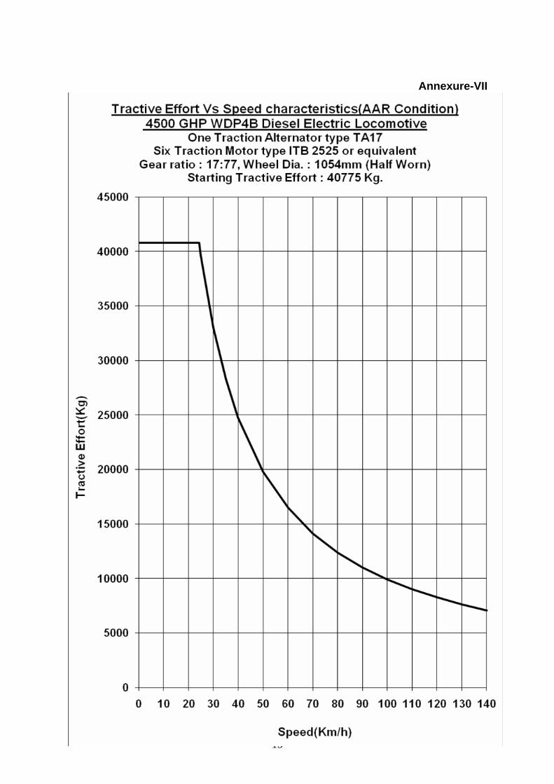
Maximum traction power - 4150 hp Starting tractive effort - 40775 kg (max.) Important particulars of WDP4B Alternator are as follows:
a) Maximum voltage : 2600 V DC
b) Maximum continuous current : 1250 A DC c) Maximum speed : 950 rpm d) Number per locomotive : One
Tractive effort Vs speed characteristics curve of WDP4B locomotive is attached at Annexure-VII for reference.
4.0 Operating environmental conditions: The environmental conditions shall be:
a) Maximum temperature } Stabled Locomotive under sun : 70º C } On board Working loco under sun : 55º C b) Minimum temperature : - 4º C
Humidity: Up to 100% during rainy season. Altitude: Up to 1750 m above mean sea level. Rainfall: Very heavy in certain areas. The bogie shall be designed to
permit locomotive running at 10 km/h in a flood water level of 102 mm above rail level.
Atmospheric condition during hot weather: Extremely dusty and desert terrain in certain areas. The dust concentration in air may reach a value of 1.6 mg/m3 max. Coastal area: The drive system shall be designed to work in coastal area in humidity, salt laden and corrosive atmosphere. The maximum values of the parameters will be as follows: a) Maximum pH value : 8.5 b) Sulphate : 7 mg per litre max. c) Max. Concentration of chlorine : 6 mg per litre d) Maximum conductivity : 130 micro siemens/cm The level of shock and vibrations to be withstood by the Drive gear system shall be as per IEC 61373 for bogie mounted / axle mounted equipments. Specific values shall be decided at the time of design approval depending on the system offered.
5.0 Track Parameters: a) Track parameters in general will be as per C&M.I vol-1. Steepest curve in
track can be up to 174 m radius. b) Track gauge : 1676 mm (nominal) c) Gauge variations:
i. On straight : -6 mm to +6 mm ii. On curve : -6 mm to +15 mm (with radius 350 m or more)
: Upto +20 mm (with radius less than 350 m) d) Track structure : 60 kg 90 UTS rails on pre-stressed sleepers, 1660
per km sleeper density, 300 mm depth of ballast cushion below the sleepers.
e) Sharpest curve & turn out to be negotiated : 174 m radius, the locomotive shall also be checked out passage in both directions over standard BG 1 in 8½ turnouts. Vogel’s layout or its internationally accepted equivalent for negotiability, throw over at headstock and coupler movement with details of clearances shall be prepared and supplied by the contractor. Maximum super elevation : 185 mm Maximum cant deficiency : 100 mm
6.0 Salient features:
6.1 Bogie design:
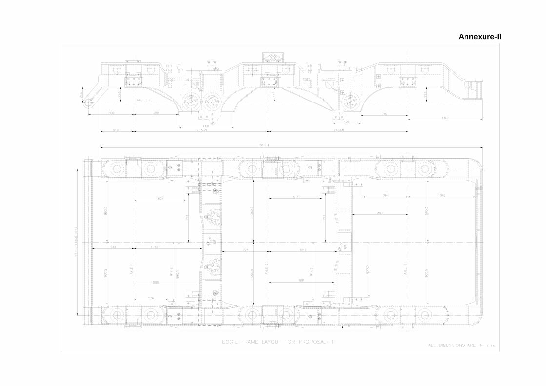
i) The bogie design shown in annexure II is already tested successfully upto 180 kmph with 2 traction motors in each bogie. The design in annexure III is being developed with a view to get speed potential upto 220 kmph.
ii) The system offered by the firm shall be suitable for fitment in a bogie similar to the one presently fitted in WDP4B/WDP4D locomotives.
iii) Any modification on bogie frame required to accommodate the motor and gear drive system needs to be identified and to be intimated before any manufacture. The tenderer shall furnish the details of modification, (if required) to RDSO and after mutual agreement only, the manufacture of the drive gear system will be undertaken.
iv) Minimum clearance of coupling part shall not be less than 102 mm in fully worn condition of wheel and bogie parts. In exceptional case, when it is not at all being possible, it may be permitted maximum up to 97 mm.
v) Equipment mounted on the bogie as well as on axle shall withstand following exceptional accelerations without permanent deformation: Bogie mounted equipments: a) Vertically - 5g b) Transversely - 5g c) Longitudinally - 5g Axle mounted equipments: a) Vertically - 20g b) Transversely - 7g c) Longitudinally - 4g
6.2 Traction motor: The tenderer shall indicate the name of the supplier of Traction motor in their offer, and get the same cleared by RDSO. The motors may be from existing RDSO approved sources of traction motor for WDP4/WDG4 class of locomotives or from internationally reputed traction motor manufacturers for locomotives. The manufacturer of the Traction motor must be experienced in manufacture of 3-phase AC transmission equipments for locomotive, and evidence establishing adequate experience in manufacturing, testing, supply and after sale service for the same shall be furnished. In case the tenderer offers a traction motor of a source other than the RDSO approved sources for WDP4/WDG4 loco Traction motors, the onus of ensuring compatibility of traction motor with loco control system/Traction Control System (TCC) will lie fully on the tenderer. Salient features of the proposed fully suspended AC traction motor:
a) 3-phase asynchronous induction motor. The motor rpm should remain close to 4000 rpm.
b) A proven insulation system shall be employed in the construction of traction motor windings having class of insulation not less than 2000C.
c) Both side bearings i.e. drive end and non drive end, shall be grease lubricated.
d) Provision of speed and temperature sensors: Speed sensors shall be Jacquet/Noris/AJB/Krauss Mafei and temperature sensors shall be PT 100 type, preferably.
e) For vibration and noise level in traction motor, IEC-60349-2 shall be taken into reference.
f) IEC-61373 for shock and vibration requirements.
6.3 Axle:
Proposed axle drawing is shown in annexure-V. The firm shall indicate any modification in the axle or any special requirement to ensure compatibility with their proposal.
6.4 Coupling: i) The effective distance between the two parts of the coupling (motor end
& gear end) shall be such as to reduce and minimize the axial movement due to radial misalignment.
ii) The dynamic stresses on the drive system while absorbing shocks/impacts at higher speeds shall be low and minimum.
iii) The two parts of the couplings should either be grease lubricated or should not require any lubrication. It shall be maintenance free.
iv) The coupling shall be able to withstand frequent shocks of magnitude 30 KN-m max.
v) The coupling shall have safety arrangement to prevent overload. vi) The weight of the coupling shall be supplied before the final design
approval. 6.5 Sealings:
i) The sealing system shall be adequate to prevent dirt/dust and water into the couplings. A non-contact type wear free labyrinth sealing shall be provided
ii) All labyrinth sealings shall be of non-contact type. iii) All rubber sealings, ‘O’ rings etc shall be oil and weather resistant and of
synthetic material. iv) There shall be no rubber or synthetic material membrane between the
two parts of the coupling. This shall be maintenance free. 6.6 Gears & Pinion:
i) The gear ratio shall be suitably decided for the said operating speed and tractive effort.
ii) The gears and pinions shall be of alloy steel with case hardening and complying with the international standard of gears and pinions being used in traction applications.
iii) The tooth pattern of gear and pinion shall be quality level 6 (min.), according to ISO:1328.
6.7 Gear box housing: i) The gear box housing shall be of Al alloy or Spheroidal graphite cast iron
(SGCI) complying with the international standards in vogue. The housing shall be tough and robust so as to withstand the impact of small objects like ballast during run.
ii) The oil lubrication arrangement inside the gear box shall be designed without necessitating the provision of oil pump. The splash lubrication offered shall be adequate to eliminate blockages of path during run for a considerable period of time without any intermittent maintenance.
iii) The quantity of oil in the housing and its sealing arrangement shall be designed in such a way that the oil replenishment is not required for 6 months.
6.8 Mounting & suspension arrangement:
i) A suitable anti-vibration mountings shall be designed for suspension of gear box housing.
ii) The mountings spheriblocks/studs shall be accessible for easy mountings and dismounting during maintenance.
7.0 Other design data: Other design data of WDP4B locomotive is attached in annexure-I for reference.
8.0 Design Review Meeting: A design review meeting shall be held at the manufacturer premises to
discuss the constructional and design details and integrability aspects including operation and maintenance of the drive gear system with fully suspended motor in the Indian Railway locomotive. In the meeting, a suitable test plan, including scope, for prototype and routine inspection, and in service performance shall be finalized. The meeting which will involve detailed design discussion together with the study of integrability aspects, will be atleast for 5 working days.
9.0 Development of Prototype Unit: 9.1 The firm shall be provided detailed drawings, layout of bogies and other items
of the locomotive which may be required for commissioning of the equipment on the locomotive. The supplier shall acquaint himself about the layout of the bogies, the reliability, maintenance and operation related issues being experienced by the Railways.
9.2 The firm shall first make one prototype after design approval by RDSO, and do prototype bench testing as per the mutually agreed upon scheme. During prototype testing, adjustments and alterations as required shall have to be done by the firm.
9.3 It shall be the responsibility of supplier to get the prototype unit assembled at IR premises under their own supervision. Necessary assistance of man power and machine & tools for non-specialized works shall be provided by IR.
10.0 Inspection & Testing: 10.1 In general, the prototype inspection shall be carried out in accordance with the
finalized test plan and relevant international standards for individual items. The manufacturer shall preferably have in-house testing jig/arrangement for complete drive gear assembly. And if not available in house, it shall have arrangement for the same with some outside agency. During testing the specified/designed load and working condition shall be generated. The product shall conform to the designed parameters with respect to its application, efficacy and effectiveness. Prototype inspection shall be done in the manufacturers premises.
10.2 The first complete integrated system shall be type tested by RDSO. The internal testing records shall also be made available.
10.3 After successful bench test, oscillation trial of one loco fitted with this system shall be conducted as per IR criteria.
11.0 Documentation, records and Suppliers responsibility: The manufacturer shall submit the following documents along with his offer and ensure their compliance.
11.1 Certificates/Approvals/Experience of the product/ manufacturer:
a) The manufacturer shall be certified for ISO 9001:2008 (the scope of the
ISO Certification shall specifically cover the manufacturing / supply of the full range of the products involved in this tender).
b) Test Reports/certificates from accredited laboratory/institute for the similar or identical design system shall be submitted.
c) Credentials/ Experience of manufacturer: The supplier shall provide reference of all those projects executed by them for various applications of same or similar systems during the last 5 years wherein they have used same/similar type of drive gear assembly for traction application.
d) The tenderer shall also indicate the details of manufacturing facility & location and details of any local infrastructure and service support in India.
e) The tenderer shall have delivered 50 sets of similar drive gear system for fully suspended traction motor for Diesel/Electric Locomotives. Performance report of the same shall be submitted by the tenderer.
11.2 The supplier shall supply detailed installation and maintenance manual for proper installation of the equipment inside the locomotive. This manual shall also include details of preventive maintenance schedules. For this purpose, the supplier shall depute his engineers/supervisors to the purchaser’s site for assistance during installation of the equipment in the locomotive.
11.3 The supplier shall associate himself during commissioning, testing and field trials of the equipment on the locomotive and depute a team of engineers/supervisors for this purpose for the first two loco sets at the place of supply.
11.4 The supplier shall arrange the required special instrumentation, if so required and carry out detailed tests in line with relevant International standards and field trials jointly with RDSO.
11.5 The supplier shall submit following traction motor curves in motoring and braking operations: RPM Vs Torque, Current Vs Torque, RPM Vs Current, PF Vs RPM and Voltage Vs RPM, RPM Vs DC Link Voltage, Speed Vs Efficiency, Speed Vs Slip, RPM Vs Effective Current, RPM Vs Peak Current.
11.6 The design data which includes technical data, outline drawing, detailed drawing of drive gear system & other attachments along with QAP shall be furnished by the supplier.
11.7 Following weight particulars shall be submitted: a. Weight of the drive gear b. Weight of any other attachment c. Weight of traction motor d. Total weight of the system e. Percentage of each weight which will be suspended f. Percentage of each weight which will be unsprung
11.8 The supplier shall also offer special tools and instruments separately which may be required for assembly and maintenance.
11.9 The supplier shall recommend a list of spares required for satisfactory maintenance and operation of drive gear system for a period of five years.
11.10 The supplier shall supply the user's manual containing instructions for assembly/disassembly during maintenance. The instructions for inspection and troubleshooting shall be clearly given.
11.11 The failure per locomotive year causing road failure shall not exceed 0.0003 (1 failure in 3300 locomotive years). Failure per locomotive year needing warranty replacement shall not exceed 0.0028 (1 failure in 357 locomotive years). The overhauling of the system shall not be required before 6 years.
11.12 The supplier shall be responsible for carrying out improvements and modifications at his own expense on all the equipments supplied, provided
such modifications/improvements are decided to be necessary for meeting the requirements of reliability, performance and safety etc, jointly by the contractor and the purchaser.
11.13 For the purpose of technical decisions on improvements/ modifications etc. on equipment, the final authority from the purchaser’s side shall be RDSO.
11.14 The supplier shall arrange for training for minimum 7 working days in their premises on operation and maintenance aspects of the complete system being supplied by them. The training will be given for 10 persons. The Boarding, lodging and travel expenditures of the IR personnel, deputed for training will be borne by IR.
12.0 Marking & packing: 12.1 The following information shall be clearly marked at a suitable place on each
component: a) Name and Address of the manufacturer. b) Year of the manufacturer.
c) Serial number of component d) Specification number
12.2 The equipment and its sub assemblies shall be packed in a wooden case of sufficient strength so that it can withstand bumps and jerks encountered in a road/rail journey.
13.0 Guarantee and Warranty: 13.1 The supplier shall be responsible for any damage to equipment due to
defective design, materials, workmanship up to a period of 24 months after commissioning or within 30 months from the date of supply, whichever is earlier. The supplier shall replace within seven days such equipment during the warranty period at his cost. The period of warranty shall be extendable in case of recurring problems attributable to defective design material or manufacturing. The supplier’s liability in respect of any complaints defects and/or claim shall be limited to the furnishing and installation of replacement parts free of any charge. Further, if any design modification is required to be made in any part of the equipment, the period of 24 months shall commence from the date when the modified part is commissioned in service. If, during the guarantee period, the equipment is out of commission on contractors account the period of guarantee shall be extended by the period for which the equipment remains out of commission.
13.2 The supplier shall be responsible for carrying out all the modifications at his cost on any part of the equipment during the period of warranty required for satisfactory operation of the equipment as per technical specification. For any technical decision the final authority from the purchaser’s side shall be RDSO.
13.3 All the replacements and repairs that the purchaser shall call upon the contractor to deliver or perform under this guarantee shall be delivered and performed by the contractor promptly and satisfactorily.
…………………
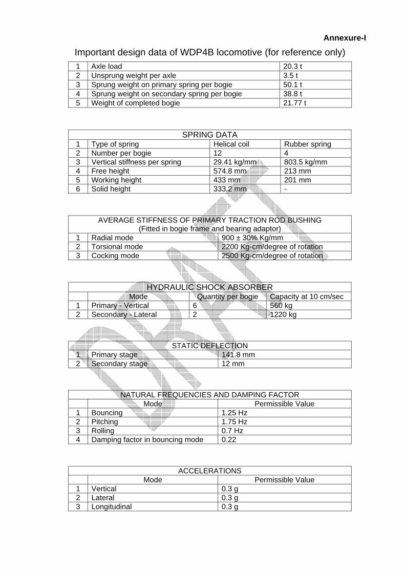
Annexure-I
Important design data of WDP4B locomotive (for reference only) 1 Axle load 20.3 t 2 Unsprung weight per axle 3.5 t 3 Sprung weight on primary spring per bogie 50.1 t 4 Sprung weight on secondary spring per bogie 38.8 t 5 Weight of completed bogie 21.77 t
SPRING DATA 1 Type of spring Helical coil Rubber spring 2 Number per bogie 12 4 3 Vertical stiffness per spring 29.41 kg/mm 803.5 kg/mm 4 Free height 574.8 mm 213 mm 5 Working height 433 mm 201 mm 6 Solid height 333.2 mm -
AVERAGE STIFFNESS OF PRIMARY TRACTION ROD BUSHING (Fitted in bogie frame and bearing adaptor)
1 Radial mode 900 ± 30% Kg/mm 2 Torsional mode 2200 Kg-cm/degree of rotation 3 Cocking mode 2500 Kg-cm/degree of rotation
HYDRAULIC SHOCK ABSORBER Mode Quantity per bogie Capacity at 10 cm/sec 1 Primary - Vertical 6 560 kg 2 Secondary - Lateral 2 1220 kg
STATIC DEFLECTION 1 Primary stage 141.8 mm 2 Secondary stage 12 mm
NATURAL FREQUENCIES AND DAMPING FACTOR Mode Permissible Value 1 Bouncing 1.25 Hz 2 Pitching 1.75 Hz 3 Rolling 0.7 Hz 4 Damping factor in bouncing mode 0.22
ACCELERATIONS Mode Permissible Value 1 Vertical 0.3 g 2 Lateral 0.3 g 3 Longitudinal 0.3 g
Annexure-II
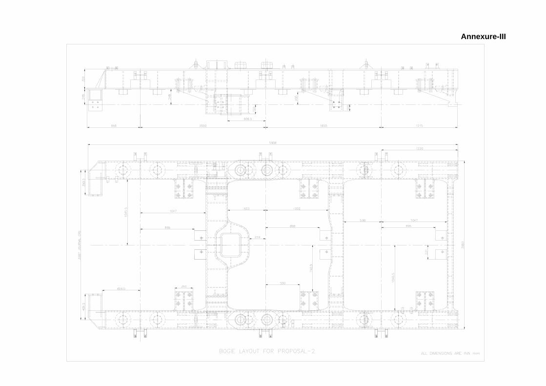
Annexure-III
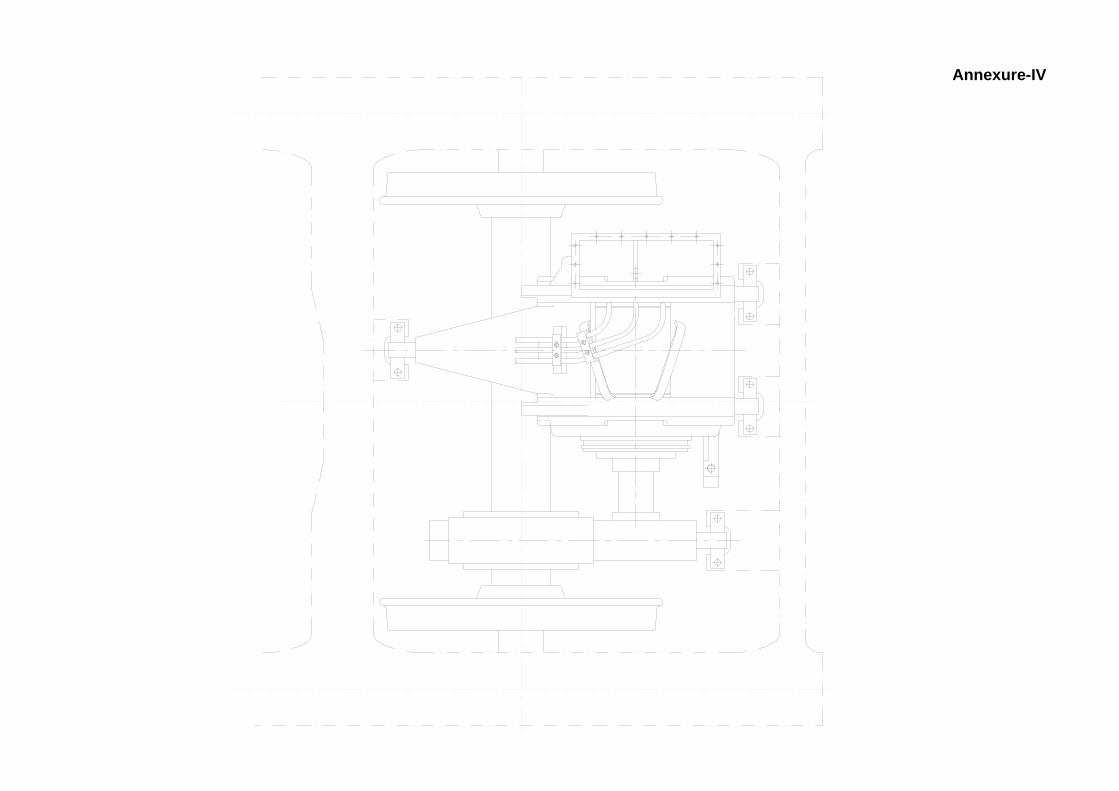
Annexure-IV
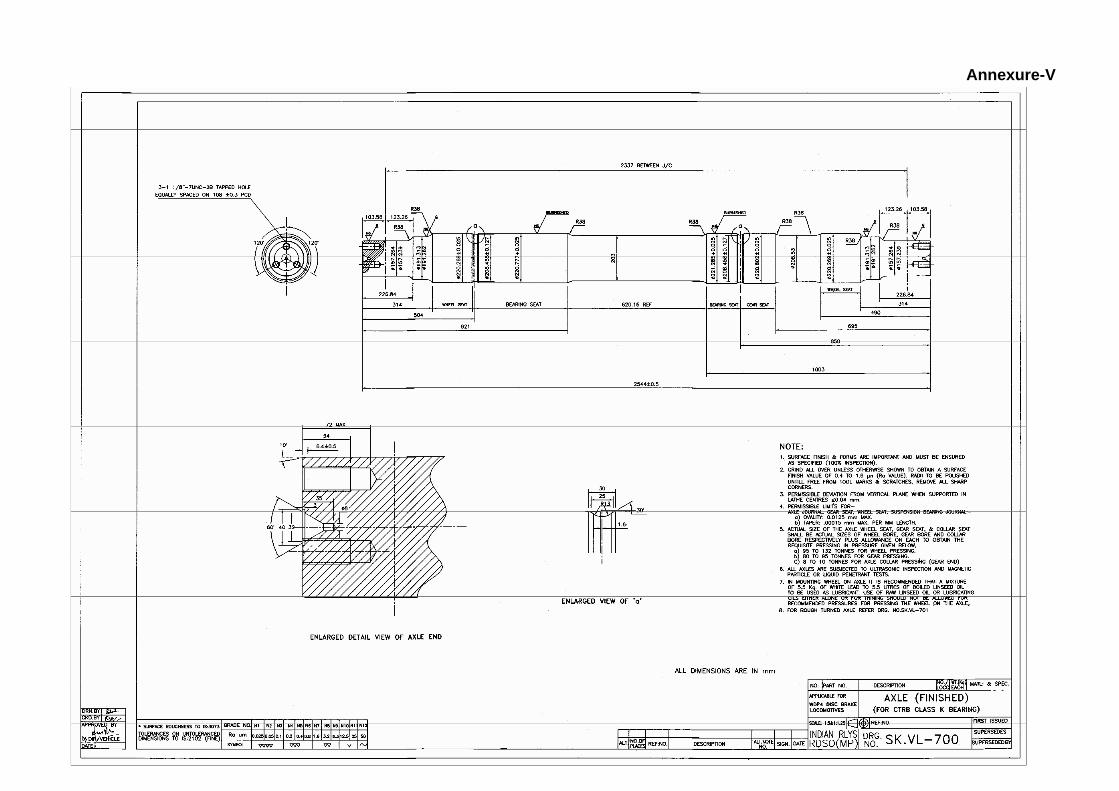
Annexure-V
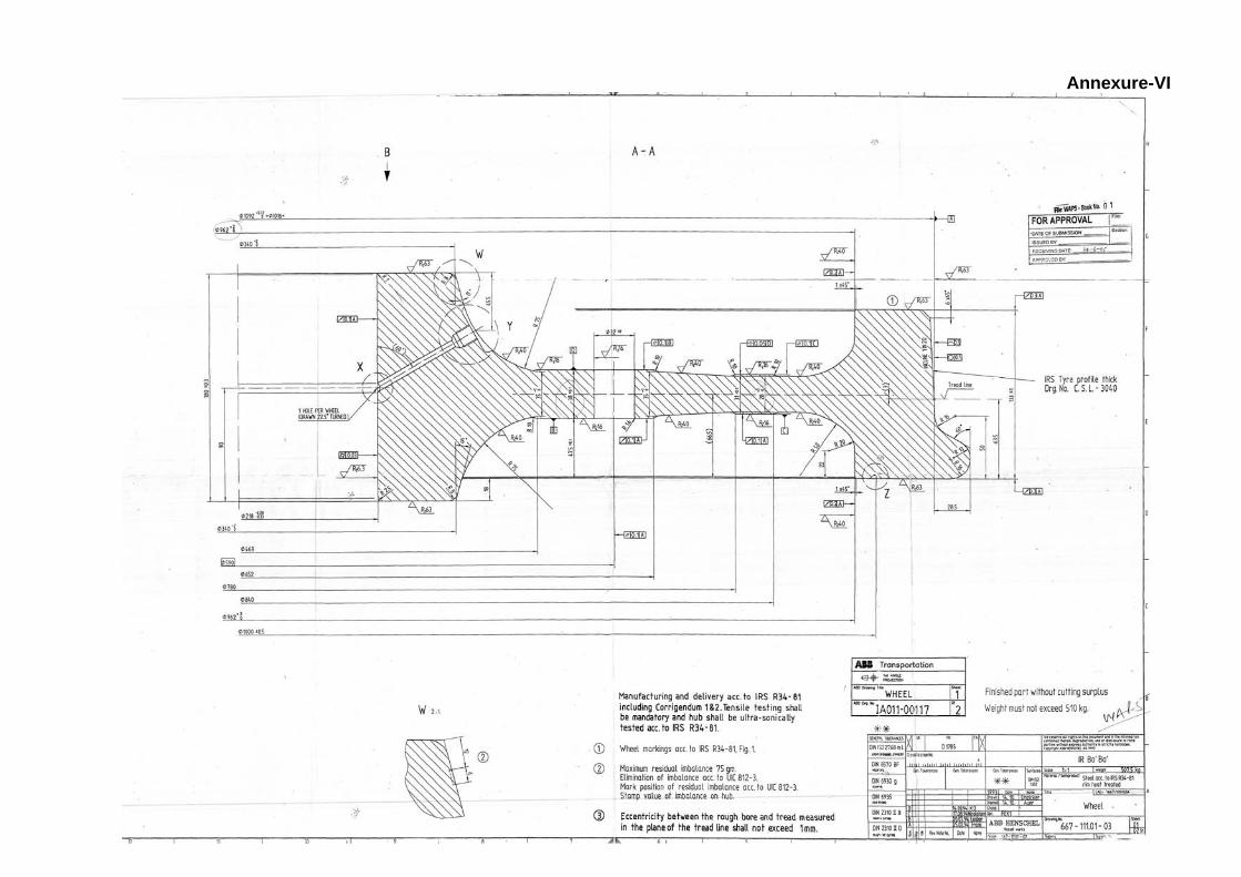
Annexure-VI
15
Annexure-VII