Embed Size (px)
Citation preview

Technical Specification
Project : "Civil, Electrical and other utility services for package -Civil- III (Overhaul complex)
VOLUME —II. TECHNICAL SPECIFICATIONS FOR TENDER NO.NK/FW/CAP-ROH-622/2010-11
Page 1 of 441
SECTION-4
CONCRETE
Indian Standards
The following IS with latest revision apply to this section:
I.S. No Subject
10262 -1982 Recommended Guide Lines for Concrete Mix Design
383-1970
Specification for coarse and fine aggregates from natural sources for concrete (Second revision)
456-2000 Code of practice for plain and reinforced concrete (Fourth revision).
516-1959 Method of test for strength of concrete.
1199-1959 Method of sampling and analysis of concrete.
2185 (part-I)-1979 Specification for load bearing, hollow concrete blocks (second revision)
2185 (Part-II)-1983 Specification for concrete masonry units Hollow and solid light weight concrete blocks (first revision)
2185 (Part-III)-1984 Specification for concrete masonry units Auto cleaved cellular (aerated) concrete blocks (first revision)
2645-1975 Specification for integral cement water proofing compounds (first revision)
4926 - 2003 Ready Mixed Concrete – Code of practice
7861 (part-I)-1971 Code of practice for extreme weather concreting Part 1-Recommended Practice for hot weather concreting
7861 (Part-Il)-1981 Code of practice for extreme weather concreting Part II-Recommended practice for cold weather concreting.
8112-1989 Specification for 43 Grade Ordinary Portland Cement
12269 - 1987 Specification for 53 Grade Ordinary Portland Cement
MATERIALS :
Cement :
Unless otherwise indicated, cement used shall be Ordinary Portland Cement 43 grade confirming to IS 8112 of approved make. Use of any other grade of cement incase of extreme emergency shall be with the specific approval from the consultant and Engineer – in – Charge. Cement older than 3 months from the date of manufacturing shall not be used for the work.
Storage:
Cement in bags shall be stored in dry waterproof sheds to protect the cement from dampness and to minimize warehouse deteriorations. Where cement has been stored for over 3 month or for any reason the stored cement shows signs of deterioration or contamination, it may be tested before use for its strength, setting time, etc., cement which has fully or partially set shall not be used.
Storage of cement at the site of work shall be at the contractor's expense and risk. In the event of any damage occurring to cement due to faulty storage in contractor's sheds or on account of negligence on his part, such damage shall be the liability of the contractor. The storage shall be planned considering optimum utilization as per planned progress and shall not allow storage of cement for longer period than
S
I G N A T U R E O F T E N D E R E R W I T H S E A L E M P L O Y E R
Project : "Civil, Electrical and other utility services for package -Civil- III (Overhaul complex)
VOLUME —II. TECHNICAL SPECIFICATIONS FOR TENDER NO.NK/FW/CAP-ROH-622/2010-11
Page 2 of 441
the specified.
Precautions in storage:
Cement bags shall not be piled against the wall. A" space of 60 cm all round shall be left between the walls and the piles, bags shall be piled off the floor on wooden planks. Bags shall be kept close together in the pile to reduce circulation of air as much as possible and shall not be piled more than 10 bags high to avoid lumping under pressure. The width of pile shall not be more than about 3m. For extra safety during the monsoon, or when it is expected to store the cement for an unusually long period, the pile shall be completely enclosed by a waterproof membrane such as polythene, tarpaulin etc. Each consignment of cement shall be stacked separately to permit easy access for inspection and facilitate removal Cement shall be used in the order in which it is received.
Aggregates from Natural Sources:
Quality of Aggregates:
Aggregates from natural sources shall consist of (crushed or uncrushed) stones, gravel and sand or combination thereof conforming to IS 383. Specification for coarse and the fine aggregates from natural sources used for concrete. They shall be hard, strong, dense, durable, clean and free from veins and adherent coatings and free from injurious amounts of disintegrated pieces, alkali, vegetable matter and other deleterious substances. As far as possible, flaky and elongated pieces shall be avoided. Aggregated shall be obtained from approved sources as indicated.
Coarse aggregates shall be obtained from crushed granite, trap, basalt or similar stones from approved quarry. Sampling and testing shall be as per 1S : 2386 .
Deleterious Materials:
Aggregates shall not contain any harmful material, such as pyrites, coal, lignite, mica, shale or similar laminated material, clay, alkali, organic impurities, soft fragments, sea shells, etc., in such quantities as to affect the strength or durability of the concrete. Aggregates to be used for reinforced concrete shall not contain any material liable to attack the steel reinforcement. Aggregates, which are chemically reactive to alkalis in cement, shall not be used in cement concrete.
Limits of Deleterious Materials:
The maximum quantities of deleterious materials in the aggregates shall not exceed the limits laid down in IS 383.
4.3.3.1 If the quantities of deleterious materials in the aggregates exceed the limits mentioned above the
aggregates shall be washed in fresh and clean water to the satisfaction of E.I.C before use.
4.3.3.2 Use of sea-sand shall not be allowed for any description of mortar and concrete works, in any location.
4.3.4 Aggregate Crushing Value:
The aggregate crushing value shall not exceed 45 percent for aggregate used for concrete other than for
wearing surfaces and 30 percent for concrete for wearing surfaces such as runways roads and pavements.
4.3.5 Aggregate Impact Value:
As an alternative to aggregate crushing value, the aggregate impact value shall not exceed 45 percent by weight for aggregates used for concrete other than for wearing surfaces and 30 percent by weight for concrete for wearing surfaces, such as runways roads and pavements.
4.3.6 Aggregate Abrasion Value:
The abrasion value of aggregate, using Los Angels machine shall not exceed the following value:
SIGNATURE OF TENDERER WITH SEAL EMPLOYER
Project : "Civil, Electrical and other utility services for package -Civil- III (Overhaul complex)
VOLUME —II. TECHNICAL SPECIFICATIONS FOR TENDER NO.NK/FW/CAP-ROH-622/2010-11
Page 3 of 441
a) For aggregates to be used in concrete for wearing surfaces-30 percent
b) For aggregates to be used in other concrete-50 percent
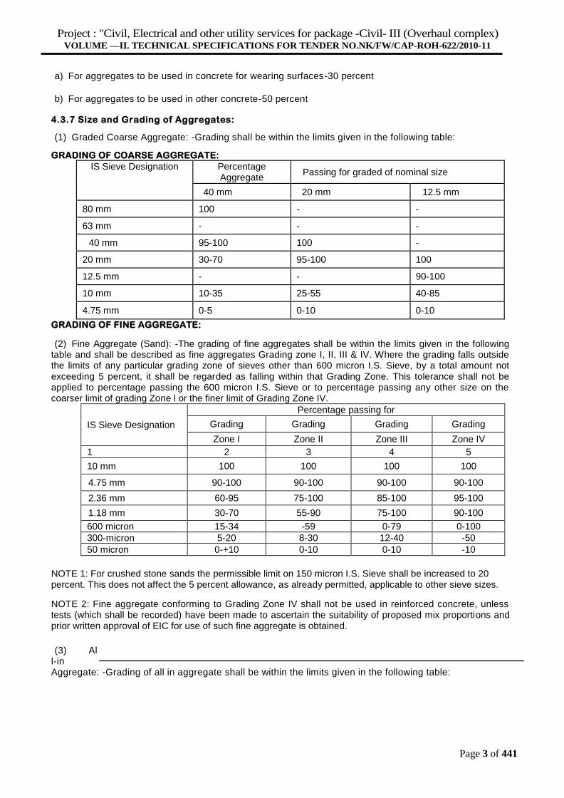
4.3.7 Size and Grading of Aggregates:
(1) Graded Coarse Aggregate: -Grading shall be within the limits given in the following table:
GRADING OF COARSE AGGREGATE:
IS Sieve Designation Percentage
Aggregate
Passing for graded of nominal size
40 mm 20 mm 12.5 mm
80 mm 100 - -
63 mm - - -
40 mm 95-100 100 -
20 mm 30-70 95-100 100
12.5 mm - - 90-100
10 mm 10-35 25-55 40-85
4.75 mm 0-5 0-10 0-10
GRADING OF FINE AGGREGATE:
(2) Fine Aggregate (Sand): -The grading of fine aggregates shall be within the limits given in the following table and shall be described as fine aggregates Grading zone I, II, III & IV. Where the grading falls outside the limits of any particular grading zone of sieves other than 600 micron I.S. Sieve, by a total amount not exceeding 5 percent, it shall be regarded as falling within that Grading Zone. This tolerance shall not be applied to percentage passing the 600 micron I.S. Sieve or to percentage passing any other size on the coarser limit of grading Zone l or the finer limit of Grading Zone IV.
IS Sieve Designation
Percentage passing for
Grading Grading Grading Grading
Zone I Zone II Zone III Zone IV
1 2 3 4 5
10 mm 100 100 100 100
4.75 mm 90-100 90-100 90-100 90-100
2.36 mm 60-95 75-100 85-100 95-100
1.18 mm 30-70 55-90 75-100 90-100
600 micron 15-34 -59 0-79 0-100
300-micron 5-20 8-30 12-40 -50
50 micron 0-+10 0-10 0-10 -10
NOTE 1: For crushed stone sands the permissible limit on 150 micron I.S. Sieve shall be increased to 20 percent. This does not affect the 5 percent allowance, as already permitted, applicable to other sieve sizes.
NOTE 2: Fine aggregate conforming to Grading Zone IV shall not be used in reinforced concrete, unless tests (which shall be recorded) have been made to ascertain the suitability of proposed mix proportions and prior written approval of EIC for use of such fine aggregate is obtained.
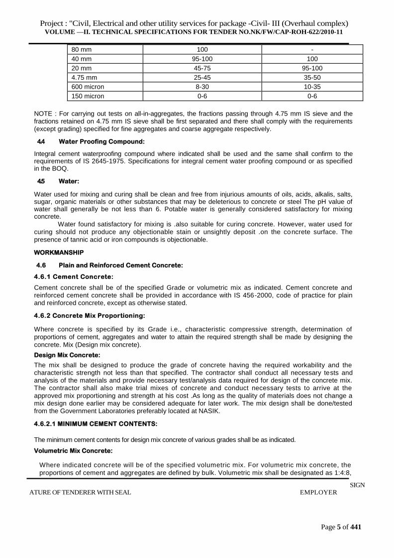
(3) All-in Aggregate: -Grading of all in aggregate shall be within the limits given in the following table:

Project : "Civil, Electrical and other utility services for package -Civil- III (Overhaul complex)
VOLUME —II. TECHNICAL SPECIFICATIONS FOR TENDER NO.NK/FW/CAP-ROH-622/2010-11
Page 4 of 441
SIGNATU
RE OF TENDERER WITH SEAL EMPLOYER
Percentage passing for All-in-Aggregate of nominal size
40 mm 20 mm ICc:e. .. -. ne-. :-. .-- .4: -. .- ............. ......2.u...........
Project : "Civil, Electrical and other utility services for package -Civil- III (Overhaul complex)
VOLUME —II. TECHNICAL SPECIFICATIONS FOR TENDER NO.NK/FW/CAP-ROH-622/2010-11
Page 5 of 441
80 mm 100 -
40 mm 95-100 100
20 mm 45-75 95-100
4.75 mm 25-45 35-50
600 micron 8-30 10-35
150 micron 0-6 0-6
NOTE : For carrying out tests on all-in-aggregates, the fractions passing through 4.75 mm IS sieve and the fractions retained on 4.75 mm IS sieve shall be first separated and there shall comply with the requirements (except grading) specified for fine aggregates and coarse aggregate respectively.
4.4 Water Proofing Compound:
Integral cement waterproofing compound where indicated shall be used and the same shall confirm to the requirements of IS 2645-1975. Specifications for integral cement water proofing compound or as specified in the BOQ.
4.5 Water:
Water used for mixing and curing shall be clean and free from injurious amounts of oils, acids, alkalis, salts, sugar, organic materials or other substances that may be deleterious to concrete or steel The pH value of water shall generally be not less than 6. Potable water is generally considered satisfactory for mixing concrete.
Water found satisfactory for mixing is .also suitable for curing concrete. However, water used for curing should not produce any objectionable stain or unsightly deposit .on the concrete surface. The presence of tannic acid or iron compounds is objectionable.
WORKMANSHIP
4.6 Plain and Reinforced Cement Concrete:
4.6.1 Cement Concrete:
Cement concrete shall be of the specified Grade or volumetric mix as indicated. Cement concrete and reinforced cement concrete shall be provided in accordance with IS 456-2000, code of practice for plain and reinforced concrete, except as otherwise stated.
4.6.2 Concrete Mix Proportioning:
Where concrete is specified by its Grade i.e., characteristic compressive strength, determination of proportions of cement, aggregates and water to attain the required strength shall be made by designing the
concrete. Mix (Design mix concrete).
Design Mix Concrete:
The mix shall be designed to produce the grade of concrete having the required workability and the characteristic strength not less than that specified. The contractor shall conduct all necessary tests and analysis of the materials and provide necessary test/analysis data required for design of the concrete mix. The contractor shall also make trial mixes of concrete and conduct necessary tests to arrive at the approved mix proportioning and strength at his cost .As long as the quality of materials does not change a mix design done earlier may be considered adequate for later work. The mix design shall be done/tested from the Government Laboratories preferably located at NASIK.
4.6.2.1 MINIMUM CEMENT CONTENTS:
The minimum cement contents for design mix concrete of various grades shall be as indicated.
Volumetric Mix Concrete:
Where indicated concrete will be of the specified volumetric mix. For volumetric mix concrete, the
proportions of cement and aggregates are defined by bulk. Volumetric mix shall be designated as 1:4:8,
SIGNATURE OF TENDERER WITH SEAL EMPLOYER
Project : "Civil, Electrical and other utility services for package -Civil- III (Overhaul complex)
VOLUME —II. TECHNICAL SPECIFICATIONS FOR TENDER NO.NK/FW/CAP-ROH-622/2010-11
Page 6 of 441
1:3:6 etc., the figures denote the relative proportions of cement, fine aggregate in dry condition and graded coarse aggregate respectively. If fine aggregate is moist, necessary allowance shall be made for bulking. To determine bulk, 50 kg of cement shall be taken as equal to 0.035 cum. Quantities of fine and coarse aggregates shall be determined by Volume separately and accurately in proper gauge boxes. The gauge boxes shall be of such dimensions that 50 kg of cement forms a unit. The equivalent size of a box for 50 kg cement bag will measure 40x 35x 25 cm internally. Consolidation of aggregates in the gauge boxes by ramming or shaking shall not be allowed.
4.6.3 Batching:
In proportioning design mix concrete, the quantity of both cement and aggregates shall be determined by weight. Water shall be either measured by volume in calibrated tanks or weighed. All measuring equipment shall be maintained in a clean serviceable condition and their accuracy periodically checked. All materials for controlled concrete shall be batched as per approved design in suitable weigh batcher of adequate capacity and of approved design.
4.6.3.1 The material shall be stockpiled for several hours, preferably a day' before use. The grading of coarse and fine aggregates shall be checked as frequently as possible, the frequency for a given job being determined by the EIC to ensure that the specified grading is maintained.
4.6.3.2 Where the aggregates supplied are not graded, different sizes shall be blended in right proportions; the different sizes being stacked in separate stock piles.
4.6.3.4 Water cement ratio shall be maintained at its correct value.
4.6.3.5 No substitutions in the materials used on the work or alterations in the established proportions shall be made without additional test to show that the quality and strength of concrete are satisfactory.
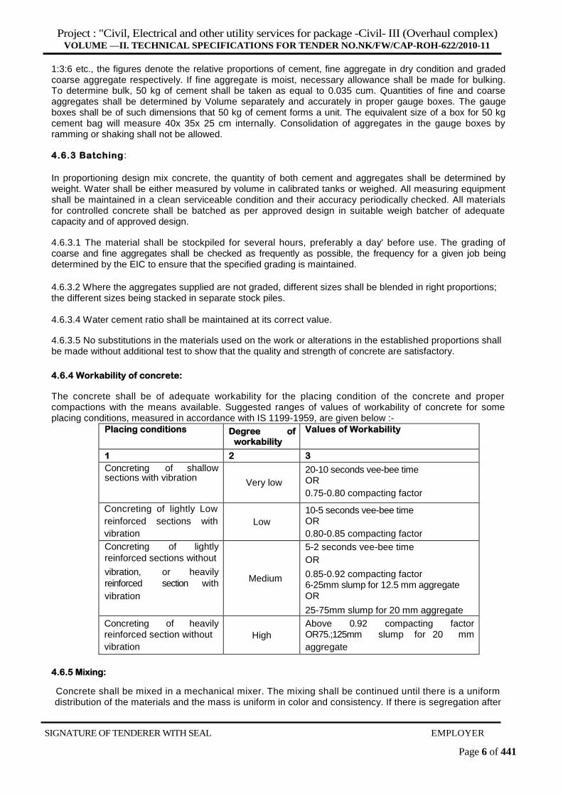
4.6.4 Workability of concrete:
The concrete shall be of adequate workability for the placing condition of the concrete and proper compactions with the means available. Suggested ranges of values of workability of concrete for some placing conditions, measured in accordance with IS 1199-1959, are given below :-
Placing conditions Degree of
workability
Values of Workability
1 2 3
Concreting of shallow sections with vibration
Very low
20-10 seconds vee-bee time OR
0.75-0.80 compacting factor
Concreting of lightly Low
reinforced sections with
vibration
Low
10-5 seconds vee-bee time OR
0.80-0.85 compacting factor
Concreting of lightly
reinforced sections without
vibration, or heavily
reinforced section with
vibration
Medium
5-2 seconds vee-bee time
OR
0.85-0.92 compacting factor 6-25mm slump for 12.5 mm aggregate OR
25-75mm slump for 20 mm aggregate
Concreting of heavily reinforced section without
vibration
High
Above 0.92 compacting factor OR75.;125mm slump for 20 mm
aggregate
4.6.5 Mixing:
Concrete shall be mixed in a mechanical mixer. The mixing shall be continued until there is a uniform distribution of the materials and the mass is uniform in color and consistency. If there is segregation after
SIGNATURE OF TENDERER WITH SEAL EMPLOYER
Project : "Civil, Electrical and other utility services for package -Civil- III (Overhaul complex)
VOLUME —II. TECHNICAL SPECIFICATIONS FOR TENDER NO.NK/FW/CAP-ROH-622/2010-11
Page 7 of 441
unloading from the mixer, the concrete shall be re-mixed. The mixing time may be taken as 1-1/2 to 2 minutes. .
4.6.6 Form Work:
4.6.6.1 General:
The formwork shall be designed and constructed to the shapes, lines and dimensions shown on the drawings. All forms shall be sufficiently watertight to prevent leakage of mortar. Forms shall be constructed so as to remove in sections. Formwork shall be provided finished fair and even as specified in section 7- Woodwork. The form work shall be properly designed so that it is rigid enough to remain free from bulging, sagging or displacement while placing the concrete and consolidation.
4.6.6.2 Cleaning and Treatment of Forms:
All rubbish particularly chippings; shavings and sawdust shall be removed from the interior of the forms before the concrete is placed. The formwork in contact with the concrete shall be cleaned and thoroughly wetted or treated with an approved composition to prevent adhesion between formwork and concrete. Care shall be taken that such approved composition is kept out of contact with the reinforcement.
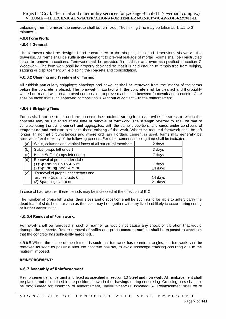
4.6.6.3 Stripping Time:
Forms shall not be struck until the concrete has attained strength at least twice the stress to which the concrete may be subjected at the time of removal of formwork. The strength referred to shall be that of concrete using the same cement and aggregates, with the same proportions and cured under conditions of temperature and moisture similar to those existing of the work. Where so required formwork shall be left longer. In normal circumstances and where ordinary Portland cement is used, forms may generally be removed after the expiry of the following periods: For other cement stripping time shall be indicated:
(a) Walls, columns and vertical faces of all structural members 2 days
(b) Slabs (props left under) 3 days
(c) Beam Soffits (props left under) 7 days
(d) Removal of props under slabs (1) Spanning up to 4.5 m (2) Spanning over 4.5 m
7 days 14 days
(e) Removal of props under beams and arches I) Spanning upto 6 m
(2) Spanning over 6 m 14 days 21 days
In case of bad weather these periods may be increased at the direction of EIC
The number of props left under, their sizes and disposition shall be such as to be 'able to safely carry the dead load of slab, beam or arch as the case may be together with any live load likely to occur during curing or further construction.
4.6.6.4 Removal of Form work:
Formwork shall be removed in such a manner as would not cause any shock or vibration that would damage the concrete. Before removal of soffits and props concrete surface shall be exposed to ascertain that the concrete has sufficiently hardened. .
4.6.6.5 Where the shape of the element is such that formwork has re-entrant angles, the formwork shall be removed as soon as possible after the concrete has set, to avoid shrinkage cracking occurring due to the restraint imposed.
REINFORCEMENT:
4.6.7 Assembly of Reinforcement :
Reinforcement shall be bent and fixed as specified in section 10 Steel and Iron work. All reinforcement shall be placed and maintained in the position shown in the drawings during concreting. Crossing bars shall not be tack welded for assembly of reinforcement, unless otherwise indicated. All Reinforcement shall be of
S I G N A T U R E O F T E N D E R E R W I T H S E A L E M P L O Y E R
Project : "Civil, Electrical and other utility services for package -Civil- III (Overhaul complex)
VOLUME —II. TECHNICAL SPECIFICATIONS FOR TENDER NO.NK/FW/CAP-ROH-622/2010-11
Page 8 of 441
tested Quality and specified Diameter as per the design. Test reports shall be submitted to Engineer – in – Charge / Consultant for approval.
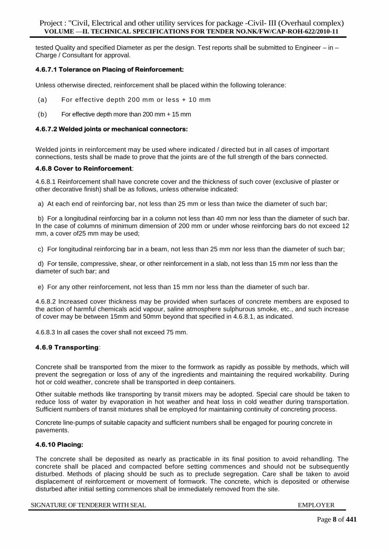
4.6.7.1 Tolerance on Placing of Reinforcement:
Unless otherwise directed, reinforcement shall be placed within the following tolerance:
(a) For effective depth 200 mm or less + 10 mm
(b) For effective depth more than 200 mm + 15 mm
4.6.7.2 Welded joints or mechanical connectors:
Welded joints in reinforcement may be used where indicated / directed but in all cases of important connections, tests shall be made to prove that the joints are of the full strength of the bars connected.
4.6.8 Cover to Reinforcement:
4.6.8.1 Reinforcement shall have concrete cover and the thickness of such cover (exclusive of plaster or other decorative finish) shall be as follows, unless otherwise indicated:
a) At each end of reinforcing bar, not less than 25 mm or less than twice the diameter of such bar;
b) For a longitudinal reinforcing bar in a column not less than 40 mm nor less than the diameter of such bar. In the case of columns of minimum dimension of 200 mm or under whose reinforcing bars do not exceed 12 mm, a cover of25 mm may be used;
c) For longitudinal reinforcing bar in a beam, not less than 25 mm nor less than the diameter of such bar;
d) For tensile, compressive, shear, or other reinforcement in a slab, not less than 15 mm nor less than the diameter of such bar; and
e) For any other reinforcement, not less than 15 mm nor less than the diameter of such bar.
4.6.8.2 Increased cover thickness may be provided when surfaces of concrete members are exposed to the action of harmful chemicals acid vapour, saline atmosphere sulphurous smoke, etc., and such increase of cover may be between 15mm and 50mm beyond that specified in 4.6.8.1, as indicated.
4.6.8.3 In all cases the cover shall not exceed 75 mm.
4.6.9 Transporting:
Concrete shall be transported from the mixer to the formwork as rapidly as possible by methods, which will prevent the segregation or loss of any of the ingredients and maintaining the required workability. During hot or cold weather, concrete shall be transported in deep containers.
Other suitable methods like transporting by transit mixers may be adopted. Special care should be taken to reduce loss of water by evaporation in hot weather and heat loss in cold weather during transportation. Sufficient numbers of transit mixtures shall be employed for maintaining continuity of concreting process.
Concrete line-pumps of suitable capacity and sufficient numbers shall be engaged for pouring concrete in pavements.
4.6.10 Placing:
The concrete shall be deposited as nearly as practicable in its final position to avoid rehandling. The concrete shall be placed and compacted before setting commences and should not be subsequently disturbed. Methods of placing should be such as to preclude segregation. Care shall be taken to avoid displacement of reinforcement or movement of formwork. The concrete, which is deposited or otherwise disturbed after initial setting commences shall be immediately removed from the site.
SIGNATURE OF TENDERER WITH SEAL EMPLOYER
Project : "Civil, Electrical and other utility services for package -Civil- III (Overhaul complex)
VOLUME —II. TECHNICAL SPECIFICATIONS FOR TENDER NO.NK/FW/CAP-ROH-622/2010-11
Page 9 of 441
4.6.10.1Before placing the concrete in trenches or on sub-grade or sub-base, the sub-grade / sub- base shall be cleaned of all injurious or foreign matter, watered and well consolidated, if necessary.
4.6.10.2 The final layer of concrete shall be laid to such levels and falls as may be directed.
4.6.10.3 When concrete has to be lowered to any depth below 15m, it shall be conveyed in suitable receptacles or by chute. The delivery end of the chute shall be as close as possible to the point of deposit. The chutes shall be thoroughly flushed with water before and after each working period, the water for this purpose shall be -discharged outside the formwork.
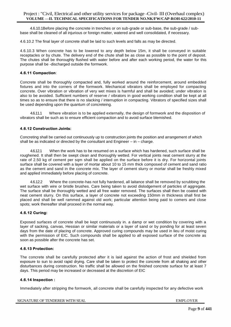
4.6.11 Compaction:
Concrete shall be thoroughly compacted and, fully worked around the reinforcement, around embedded fixtures and into the corners of the formwork. Mechanical vibrators shall be employed for compacting concrete. Over vibration or vibration of very wet mixes is harmful and shall be avoided; under vibration is also to be avoided. Sufficient numbers of reserve / vibrators in good working condition shall be kept at all times so as to ensure that there is no slacking / interruption in compacting. Vibrators of specified sizes shall be used depending upon the quantum of concreteing.
4.6.11.1 Where vibration is to be applied externally, the design of formwork and the disposition of vibrators shall be such as to ensure efficient compaction and to avoid surface blemished.
4.6.12 Construction Joints:
Concreting shall be carried out continuously up to construction joints the position and arrangement of which shall be as indicated or directed by the consultant and Engineer – in – charge.
4.6.12.1 When the work has to be resumed on a surface which has hardened, such surface shall be roughened. It shall then be swept clean and thoroughly wetted. For vertical joints neat cement slurry at the rate of 2.50 kg of cement per sqm shall be applied on the surface before it is dry. For horizontal joints surface shall be covered with a layer of mortar about 10 to 15 mm thick composed of cement and sand ratio as the cement and sand in the concrete mix. The layer of cement slurry or mortar shall be freshly mixed and applied immediately before placing of concrete.
4.6.12.2 Where the concrete-has not fully hardened, all laitance shall be removed by scrubbing the wet surface with wire or bristle brushes. Care being taken to avoid dislodgement of particles of aggregate. The surface shall be thoroughly wetted and all free water removed. The surfaces shall then be coated with neat cement slurry. On this surface, a layer of concrete not exceeding 150mm in thickness shall first be placed and shall be well rammed against old work; particular attention being paid to comers and close spots; work thereafter shall proceed in the normal way.
4.6.12 Curing:
Exposed surfaces of concrete shall be kept continuously in. a damp or wet condition by covering with a layer of sacking, canvas, Hessian or similar materials or a layer of sand or by ponding for at least seven days from the date of placing of concrete. Approved curing compounds may be used in lieu of moist curing with the permission of EIC. Such compounds shall be applied to all exposed surface of the concrete as soon as possible after the concrete has set.
4.6.13 Protection:
The concrete shall be carefully protected after it is laid against the action of frost and shielded from exposure to sun to avoid rapid drying. Care shall be taken to protect the concrete from all shaking and other disturbances during construction. No traffic shall be allowed on the finished concrete surface for at least 7 days. This period may be increased or decreased at the discretion of EIC
4.6.14 Inspection :
Immediately after stripping the formwork, all concrete shall be carefully inspected for any defective work
SIGNATURE OF TENDERER WITH SEAL EMPLOYER
Project : "Civil, Electrical and other utility services for package -Civil- III (Overhaul complex)
VOLUME —II. TECHNICAL SPECIFICATIONS FOR TENDER NO.NK/FW/CAP-ROH-622/2010-11
Page 10 of 441
and defects either removed or made good before the concrete has thoroughly hardened.
4.6.15 Exposed Surfaces :
4.6.15.1.1 The contractor shall use proper formwork so that the concrete in contact with removal of formwork present an even surface. Concrete while being poured against formwork shall be adequately tamped, or vibrated where directed, so that fines are drawn towards the surface and honey combing is avoided.
4.6.15.2 Exposed surfaces of concrete shall be "Finished fair and Even in Forms".
Exposed surfaces after striking off formwork shall be such as to present a fair and even surface and shall not be plastered unless otherwise specified. The surface shall be presentable without any further treatment. Any irregularities and protruding formwork marks shall be removed and minor honeycombing made good with cement and sand mortar 1:3. Lines along the formwork joints may however show.
4.6.15.3 Exposed surfaces of concrete which are indicated/required to be plastered shall be roughened with wire brushes and hacked out closely immediately after removal of formwork.
4.6.15.4 Openings and Inserts :
Openings and Positions of Inserts shall be made as per the drawing or as directed by the Consultant and EIC.This shall be done with atmost accuracy/precision and any deviation from the Drawing or instruction by the Consultant or EIC, the same shall be rectified by the Contractor at his own cost. No Extra payment shall be admissible for making openings/inserts etc.
4.6.16 Sampling and testing of concrete: Samples from fresh concrete shall be taken as per IS 1199-1959. Method of sampling of concrete and cubes shall be made, cured and tested at 28 days in accordance with IS 516-1959, Method of test for strength of concrete.
4.6.16.2.1 Where indicated, tests on beams for modulus of rupture at 72 ± 2hrs or at 7 days, or compressive strength tests at 7 days may be carried out in addition to 28 days compressive strength alone shall be the criterion for acceptance or rejection of the concrete.
4.6.16.3 Test Specimen:
Three test specimens shall be made from each sample for testing at 28 days. Additional cubes may be required for such purpose as to determine the strength of concrete at 7 days or to check the testing errors.
4.6.16.4 Test Strength of samples:
The test strength of the sample shall be the average of the strength of three specimen. The individual variation shall not be more than +/- 15 percent of the average.
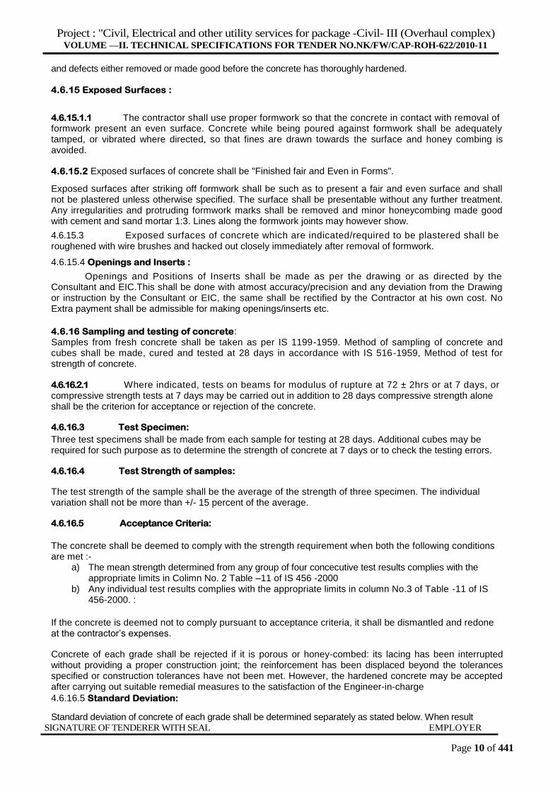
4.6.16.5 Acceptance Criteria:
The concrete shall be deemed to comply with the strength requirement when both the following conditions are met :-
a) The mean strength determined from any group of four concecutive test results complies with the appropriate limits in Colimn No. 2 Table –11 of IS 456 -2000
b) Any individual test results complies with the appropriate limits in column No.3 of Table -11 of IS 456-2000. :
If the concrete is deemed not to comply pursuant to acceptance criteria, it shall be dismantled and redone at the contractor’s expenses.
Concrete of each grade shall be rejected if it is porous or honey-combed: its lacing has been interrupted without providing a proper construction joint; the reinforcement has been displaced beyond the tolerances specified or construction tolerances have not been met. However, the hardened concrete may be accepted after carrying out suitable remedial measures to the satisfaction of the Engineer-in-charge
4.6.16.5 Standard Deviation:
Standard deviation of concrete of each grade shall be determined separately as stated below. When result SIGNATURE OF TENDERER WITH SEAL EMPLOYER

Project : "Civil, Electrical and other utility services for package -Civil- III (Overhaul complex)
VOLUME —II. TECHNICAL SPECIFICATIONS FOR TENDER NO.NK/FW/CAP-ROH-622/2010-11
Page 11 of 441
of sufficient number of tests (at least 30) are not available, than depending on the degree of quality control expected to be exercised at the site, the value of standard deviation given in the following table may be adopted for guidance. Grade of Concrete Suggested Values of S.D
Grade of Concrete S.D. for different degree of control in N/mm2
Very Good Good Fair
M 10 2 2.3 3.3
M 15 2.5 3.5 4.5
M 20 3.6 4.6 5.6
M 25 4.3 5.3 6.3
M 30 5 6 7
M 35 5.3 6.3 7.3
M 40 5.6 6.6 7.6
Control expected for this work is "Very Good" and the contractor shall deploy weigh batcher as required to attain the required control 4.7 Waterproof Concrete:-
Where indicated, cement concrete shall be waterproofed by adding integral waterproofing compound conforming to IS 2645-1975, Specification for integral cement waterproofing compounds at the time of making concrete as per the manufacturer's instructions. The quality of waterproofing compound shall be as indicated but in no case shall be less than the quality recommended by the manufacturers and not exceeding 3 percent by weight of cement.
4.8 Work in Extreme Weather Concreting:
Concreting during hot and cold weather shall be done as per the procedures set out-in IS: 7861 (part-I) Code of practice for extreme weather concreting; part I Recommended practice for hot weather concreting, or IS7861 (part-II)-1981 Code of practice for extreme weather concreting; Part II Recommended practice for cold weather concreting.
4.9 Reinforced Concrete Work in water Retaining Structure:
4.9.1.1 Special care shall be taken to get the most suitable grading of aggregate so as to produce the densest possible concrete. Mix proportion shall be indicated. Water cement ratio shall be controll ed consistent with the requirements of workability to produce impervious concrete.
4.9.2 The concrete between the reinforcement and the formwork on the water face shall be well compacted and the board joints tight, so as to produce a face free from honey-combing or pores. External vibrators viz. shutter vibrators at the rate of one vibrator per 2.5 m
2 of shutter area shall be used to produce
a compact concrete with a dense skin which shall not, however, contain an excess of cement, wherever it is not possible to use shutter vibrator, pin vibrator shall be used after the approval of EIC.
4.9.3 Construction, Contraction & Expansion Joints.
4.9.3.1 All vertical, horizontal construction and expansion joints in water retaining structures shall be located and executed as shown in the drawings and no deviation shall be permitted without the specific permission of EIC. Where days' work joints are formed whether horizontally or vertically, they shall be rebated as called out on drawings. Care shall be taken to remove from the earlier lift over all loose pieces of gravel, stone chips, wooden chips, country nails or any other foreign materials. All laitance shall also be thoroughly removed. If necessary, the face of the old concrete shall be well hacked to expose the aggregate and after washing the surface, a thin coat of mortar or grout (1 cement: 1 sand) shall be applied immediately before resuming concreting.
4.9.3.2 Water bar installation along the joints shall be done by embedding one half of the water bar in each side of the joint by suitable jigs / supporting arrangements between the adjacent sections of the concrete as per the manufacturer's specifications and directions of the EIC. Water bars shall be properly aligned and placed in position during embedding. To achieve the continuity of the water bar all along the joint at crossing and at change of alignment, the water stops shall be welded (in T,X or L shapes as the case may be) as per manufacturer's specifications and directions of EIC. Suitable jigs manufactured out of reinforcing
SIGNATURE OF TENDERER WITH SEAL EMPLOYER
Project : "Civil, Electrical and other utility services for package -Civil- III (Overhaul complex)
VOLUME —II. TECHNICAL SPECIFICATIONS FOR TENDER NO.NK/FW/CAP-ROH-622/2010-11
Page 12 of 441
bars may be used for fixing the water bars.
4.9.3.3 Fittings:
Pipes and outer fittings passing through the walls and bottom shall be well embedded in the concrete and shall be provided with normal puddle flanges. Opening in the walls, and floor slabs if any shall be provided as per the relevant drawings.
4.9.4 Curing :
Concrete in water retaining portion shall be cured minimum for 21 days.
4.9.5 Hydraulic Testing:
Structures shall be tested strictly in accordance with IS: 3370 (Part I) for water tightness. For underground tank, the total maximum drop in water surface level over seven days shall not exceed 40 mm.
4.10 Pre-cast Reinforced Concrete-Generally
4.10.1.Pre-cast reinforced concrete articles such as manhole cover and frame,columns, fencing posts, door and window frames, lintels, chajjas, copings, sills, shelves, slabs, louvers etc. shall be of the grade or mix as indicated and cast in forms or moulds. The forms shall be of timber or of steel for better finish. Provisions shall be made in the forms and moulds to accommodate fixing devices such as nibs, clips, hooks, bolts and forming of notches and ho les. The contractor may precast the units on cement or steel platform that shall be adequately oiled provided the surface finish is of the same standard as obtained in the forms. Each until shall be cast in one operation.
4.10.2 Concrete shall be proportioned, mixed, placed and thoroughly compacted by vibration or tamping to give a dense concrete free from voids and honeycombing.
4.10.3 Precast articles shall have a dense surface finish showing no coarse aggregate and shall have no cracks or crevices likely to assist in disintegration of concrete or rusting of steel or other defects that would interfere with the proper placing of the units or to impair the strength or the performance of construction. All angles of the precast units with the exception of the angles resulting from the splayed or the chamfered faces shall be true right angles. The rises shall be clean and sharp except those specified to be rounded. The wearing surface shall be true and out of winding. On being fractured, the interior of the units shall present a clean, homogeneous appearance.
4.10.4 The longitudinal reinforcement shall have a minimum cover of 12 mm or twice the diameter of the main bar, whichever is more, unless otherwise directed.
4.10.5 Curing :
After placing, the concrete shall be adequately protected during setting and in first stages of hardening from shocks and from the harmful effects of sunshine, drying winds and cold. The concrete shall be cured for at least 7 days.
4.10.6 Maturing:
From the date of casting, the precast articles shall be matured for 28 days before erection or being built up.
4.10.7 Concrete shall have sufficient strength to prevent damage to units when first handled.
Flyash :
Addition of flyash may be considered to the extent of 10% only and not more for footings, pedestals, columns , slabs and beams. Flyash shall not be used for Pavements and floors.
Nevertheless of what is specified herein above or not, IS – 456,516,10262 and 1199 shall be followed related to all the matters of concrete specified therein.

Project : "Civil, Electrical and other utility services for package -Civil- III (Overhaul complex)
VOLUME —II. TECHNICAL SPECIFICATIONS FOR TENDER NO.NK/FW/CAP-ROH-622/2010-11
Page 13 of 441
SIGNATURE OF TENDERER WITH SEAL EMPLOYER

Project : "Civil, Electrical and other utility services for package -Civil- III (Overhaul complex)
VOLUME —II. TECHNICAL SPECIFICATIONS FOR TENDER NO.NK/FW/CAP-ROH-622/2010-11
Page 14 of 441
4.10.8 Marking:
Precast articles shall be clearly marked to indicate the top of member and its location and orientation in the structure. While the 'concrete is still green, each unit shall be marked with the date of casting. Precast units shall be stored, transported and placed in position in such a manner that they will not be over stressed or damaged.
4.11 Epoxy resin concrete bonding agent
Scope of work.
For bonding new cementitious materials to existing cementitious surfaces. For use on horizontal surfaces and on vertical surfaces where mortar or concrete can be supported by formwork. Where extension to existing structure or similar work is ordered . The following strengths should be achieved as Per table below:
Compressive Strength BS 6319 Pt - 2 @ 7 days 50 N/mm2
Flexural strength BS 6319 Pt 3 @ 7 days 35 N/mm2
Tensile strength BS 6319 Pt 7 @ 7 days 20 N/mm
2
Shear strength BS 6319 Pt 4 @ 7 days 10 N/mm2
Adhesive strength to concrete: In general the bond strength will always exceed the tensile strength of M30 concrete.
The Tests shall be carried out at manufacturers laboratory and results shall be submitted to the consultant / EIC for approval
Specification clauses
The bonding agent shall be an epoxy based two component resin system pre packed in distinct colours to give visual evidence for proper mixing. The bonding agent should remain in tacky state after application for a minimum period of 6 hours at 30°C. There shall not be bond failure of the specimen when tested by slant shear method according to BS 6319 pt 4.
Application instructions
Preparation
All surfaces to be treated must be firm, dust free and clean. All laintence should be removed by etching with Reebaklens and wire-brushing. Where ever necessary, the existing concrete must be chipped to a sound substrate. Where surfaces are contaminated with oil or grease, this should be removed by using a strong industrial detergent or organic degreaser. Surface should be washed thoroughly with water and dried before the application.
Mixing
The entire contents of the hardener shall be poured into the resin container and the two materials thoroughly mixed until a uniform colour is obtained. To facilitate application at temperatures below 10 °C the separate components should be warmed in hot water to a maximum of 25 °C before mixing.
Coating
Mixed Epoxy resin bonding agent should be brush applied to the prepared surface. The new concrete should be placed within 6 hours at 30°C to the coated substrate, when it is in a tacky state.
Rate

Project : "Civil, Electrical and other utility services for package -Civil- III (Overhaul complex)
VOLUME —II. TECHNICAL SPECIFICATIONS FOR TENDER NO.NK/FW/CAP-ROH-622/2010-11
Page 15 of 441
S
IGNATURE OF TENDERER WITH SEAL EMPLOYER

Project : "Civil, Electrical and other utility services for package -Civil- III (Overhaul complex)
VOLUME —II. TECHNICAL SPECIFICATIONS FOR TENDER NO.NK/FW/CAP-ROH-622/2010-11
Page 16 of 441
The rate shall include the cost of all labour and materials involved in all the above operations and testing (including surface preparation) described above. No Extra Payment shall be made for Testing.
4.12 High strength, non-shrink, cementitious grout
Description of work:It is used for grouting of base plates of Columns, stanchions, and similar applications etc.,
Description of material: This material is supplied as a ready to use dry powder. The addition of a controlled amount of clean water produces a free flowing, non-shrink grout for gap thicknesses up to 100mm.
This material is a blend of Portland cement, graded fillers and chemical additives which impart controlled
expansion in the plastic state whilst minimizing water demand. The low water demand ensures high early
strength. The graded fillers are designed to assist uniform mixing and produce a consistent grout.
The Tests shall be carried out at at approved Govt. laboratory and results shall be submitted to the
consultant / EIC for approval
Specification Clauses
Performance specification
All grouting shown on the drawing must be carried out with a pre packed cement based product which is
chloride free.It shall be mixed with clean water to the required consistency. The grout must not bleed or
segregate.A positive volumetric expansion shall occur while the grout is plastic by means of gaseous
system. The compressive strength of the grout must exceed 50 N/mm2 at 7 days and 60 N/mm
2 at 28 days as
per Code (BS 1881 - Part 116: 1983). The flexural strength of grout must exceed 9N/mm2 @ 28 days as per
Code ( BS 4551, 1998). The fresh wet density of the mixed grout must exceed 2150 kg/ m3.
The storage, handling and placement of the grout must be in strict accordance with the manufacturer's
instructions.
Application instructions
Preparation Foundation surface
The substrate surface must be free from oil, grease or any loosely adherent material. If the concrete surface
is defective or has laitence, it must be cut back to a sound base. Bolt holes and fixing pockets must be blown
clean of any dirt or debris.
Pre-soaking
Several hours prior to placing, the concrete substrates should be saturated with fresh water. Immediately
before grouting takes place any free water should be removed with particular care being taken to blow out all
bolt holes and pockets.
Base plate
It is essential that this is clean and free from oil, grease or scale. Air pressure relief holes should be
provided to Allow venting of any isolated high spots. Leveling shims If these are to be removed after the
grout has hardened, they should be treated with a thin layer of grease.
Formwork
The formwork should be constructed to be leak proof. This can be achieved by using foam rubber strip or
mastic sealant beneath the constructed formwork and between joints.In some cases it is practical to use
sacrificial semi-dry sand and cement formwork. The formwork should include outlets for pre-soaking.
Unrestrained surface area.

Project : "Civil, Electrical and other utility services for package -Civil- III (Overhaul complex)
VOLUME —II. TECHNICAL SPECIFICATIONS FOR TENDER NO.NK/FW/CAP-ROH-622/2010-11
Page 17 of 441
SIGNATURE OF TENDERER WITH SEAL EMPLOYER
Project : "Civil, Electrical and other utility services for package -Civil- III (Overhaul complex)
VOLUME —II. TECHNICAL SPECIFICATIONS FOR TENDER NO.NK/FW/CAP-ROH-622/2010-11
Page 18 of 441
This must be kept to a minimum. Generally the gap width between the perimeter formwork and the plate edge should not exceed 150mm on the pouring side and 50mm on the opposite side. It is advisable, where practical, to have no gap at the flank sides.
Mixing and placing
Mixing
For best results a mechanically powered grout mixer should be used. When quantities up to 50kg are used,
a heavy duty slow speed drill (400-500 rpm) fitted with a paddle is suitable larger quantities will require a
heavy duty mixer.
To enable the grouting operation to be carried out continuously, it is essential that sufficient mixing capacity
and labour are available. The use of a grout holding tank with provision to gently agitate the grout may be
required.
Consistency of grout mix
The quantity of clean water required to be added to a 25kg bag to achieve the desired consistency as
given in table below :
Pourable 4.125 litres
Flowable 4.500 litres
Placing
At 30°C place the grout within 20 minutes of mixing to gain full benefit of the expansion process.Grouting
material can be placed in thicknesses up to 100mm in a single pour when used as an under plate grout.
For thicker sections it is necessary to fill out grouting material with well graded silt free aggregate to minimize heat buildup. Typically a 10mm aggregate is suitable. 50 - 100% aggregate weight of grouting material can be added.
Rate
The rate shall include the cost of all labour and materials involved in all the above operations and testing as described above. No Extra Payment shall be made for Testing.
BATCH MIXING PLANT
Central Mixed Concrete Batching Plant specified capacity in General Conditions of Contract (Volume I) shall be set up by the contractor
4.13 READY MIX CONCRETE
(IF SPECIFICALLY PERMITTED BY ENGINEER IN CHARGE ON EMERGENCY) SPECIFICATIONS for RMC:
Contractor shall make ready mixed concrete with who is expert in the field, would supply designed mix. The RMC producer accepts the responsibility for the design of the mixture for the desired performance. The contractor shall specifies aggregate size, slump, air content, cement content, or weight of cement per cubic meter of concrete, maximum water content and admixtures required. The contractor shall accept the responsibility for concrete strength and its performance.
PROPORTIONING OF RMC:
The proportioning of an RMC aims at obtaining the properties, such as workability, strength, durability and appearance. The following basics of a good concrete mix should be considered while proportioning RMC Concrete aggregates should be clean, strong and durable. Fly ash or other supplementary cementitious materials added as directed if necessary by EIC to RMC to enhance concrete properties

Project : "Civil, Electrical and other utility services for package -Civil- III (Overhaul complex)
VOLUME —II. TECHNICAL SPECIFICATIONS FOR TENDER NO.NK/FW/CAP-ROH-622/2010-11
Page 19 of 441
S
IGNATURE OF TENDERER WITH SEAL EMPLOYER
Project : "Civil, Electrical and other utility services for package -Civil- III (Overhaul complex)
VOLUME —II. TECHNICAL SPECIFICATIONS FOR TENDER NO.NK/FW/CAP-ROH-622/2010-11
Page 20 of 441
Admixtures are commonly used to improve the rate of setting and strength of development of concrete as directed by EIC
CENTRAL- MIXED CONCRETE:
. Concrete batch plants include a stationary, plant mounted mixer that mixes the concrete before it is discharged into a truck mixer. While traveling to the job site the drum is turned at agitating speed (slow speed). After arriving at the job site, the concrete is completely mixed. The drum is then turned for 70 to 100 revolutions, or about 5 minutes, at mixing speed.Concrete mixed in the yard or central batching plant: The drum is turned at high speed or 12-15 rpm for 50 revolutions. This allows quick check of batch. The concrete is then agitated slowly while driving to the job site. Concrete mixed in transit: The drum is turned at medium speed or about 8 rpm for 70 revolutions while driving to the job site.
DELIVERY OF RMC:
Ready mix concrete can be delivered to the construction site in truck- mounted, rotating drum mixers. Truck mixers have a revolving drum with the axis inclined to horizontal. To load or charge the raw materials from a transit mixed plant or central mixed plant into the truck, the drum must be turned very fast in the changing direction. After the concrete is loaded and mixed, it is normally hauled to the job site with the drum turning at the speed of less than 2 rpm. The truck mixer shall have discharge units to convey through the pump to desired location in the site.
INSPECTION AND TESTING:
Specific control tests and evaluations are required during the manufacturing process to produce predictable high quality concrete. The concrete shall undergo all the specified test for concrete as per IS codes.
4.14 Plasticizer
Scope of work
To produce high workability concrete without loss of strength and to promote high early and ultimate strengths by taking advantage of water reduction whilst maintaining workability. To produce high quality concrete of improved durability and impermeability. At higher dosages, advantages can be taken of the retardation of initial setting time of concrete especially in large pours.
Standards compliance
Plasticizer should conform to IS: 9103- 1999 and carries license from Bureau of Indian Standards. It should complies with IS 2645: 1975 and BS 5075 Part 3 and ASTM C494 Type F and chloride content should be
nil as per IS 456
Description of material
Plasticizer is based on a blend of specially selected organic polymers and disperses the cement particles effectively in the concrete mix and hence exposes a larger surface area to the hydration process. This effect is used either to increase the strength or to produce high workability concrete or reduce cement content of concrete or to retard the setting time of concrete
Application instructions
Application process as per manufacturer’s specifications and contractor should submit the technical literature & get approval from the EIC and the material should be used within the shelf time.
SIGNATURE OF TENDERER WITH SEAL EMPLOYER

Project : "Civil, Electrical and other utility services for package -Civil- III (Overhaul complex)
VOLUME —II. TECHNICAL SPECIFICATIONS FOR TENDER NO.NK/FW/CAP-ROH-622/2010-11
Page 21 of 441
SECTION-5
BRICK WORK
5.1 Indian standards
The following IS with latest revision apply to this section:
LS. No. Subject
195-1963 Specification for fire clay mortar for laying fire clay refractory bricks (second revision)
702-1988 Specification for industrial bitumen (second revision)
1077-1986 Specification for common burnt clay building bricks (fourth reversion)
1526-1960 Sizes and shapes for fire bricks (230mm. series)
1580-1969 Specification for bituminous compounds for water proofing and caulking purposes
(first reversion)
1905-1980 Code for practice for structural safety of building masonry wall (second revision)
2116-1980 Specification for sand for masonry mortars (first revision)
2386 (Part II) Methods of test for aggregates for concrete. Part II -Estimation of deleterious
1963 materials and organic impurities.
2691-1988 Specification for burnt clay facing bricks (second revision)
4832 (Part II) 1969
Specification for chemical resistance mortars, Part II, Resin type.
4832 (Part III) 1968
Specification for chemical resistance mortars, Part III, sulphor type.
5454-1978 Methods for sampling of clay building brick (first revision)
4860-1968 Specification for acid resistance bricks.
6165-1971 Dimension for special shapes of clays bricks.
MATERIALS
5.2 CEMENT
Unless otherwise indicated, Cement shall be Ordinary Portland cement, 43 grade conforming to IS 8112 of approved make/ brand. Use of any other grade of cement incase of extreme emergency shall be with the specific approval from the consultant and Engineer – in – Charge.
5.3 DELETED
5.4 Sand for Masonry Mortars
Unless otherwise indicated, sand for mortars shall consist of natural sand, crushed stone sand or crushed gravel sand or a combination of any of these conforming to IS 2116-1980:, specification for sand for masonry mortars. Sand shall be hard, durable, clean and free from adherent coatings and shall not contain clay and impurities such as iron pyrites, alkalies, salts, coal, mica, shale or similar laminated or other materials exceeding the specified limits.
5.4.1 The maximum quantities of clay, fine silt and fine dust in sand shall not be more than 5 percent by mass. Organic impurities shall be below that obtained, by comparison with the standard solution specified in 6.2.2 of IS 2386 {Part II)-1963. Method of test for aggregate for concrete, Part II Estimation of deleterious material and organic impurities.
5.5 DELETED

Project : "Civil, Electrical and other utility services for package -Civil- III (Overhaul complex)
VOLUME —II. TECHNICAL SPECIFICATIONS FOR TENDER NO.NK/FW/CAP-ROH-622/2010-11
Page 22 of 441
S
IGNATURE OF TENDERER WITH SEAL EMPLOYER
5.6 Common Burnt Clay Building Bricks
5.6.1 Common burnt clay building bricks (hereinafter termed as bricks) shall conform to the requirements laid down in IS 1077 -1992, specifications for Common burnt clay building bricks. The class of bricks (based on minimum average compressive strength) viz 3.5(or35), 5(or50) as mentioned below, shall be as indicated. Bricks shall be neither overburnt nor under burnt and shall be free from cracks, or any other such defects.
5.6.2 Sub Class A bricks shall have smooth rectangular faces with sharp corners and shall be uniform in color. Sub Class 'B' bricks may have slight distorted and round edges provided no difficulty arise on this account in laying of uniform courses.
5.6.3 Dimensions: Size of bricks shall be as indicated. Standard of bricks are as under:
5.6.4 Tolerance:
Nominal Size Actual Size
Modular Bricks 20x10x10cm 19x9x9 cm
Old size Bricks(FPS) 9x4.5x3 inches or 23x1 1.3x7.5
cm or 25 x 12.5 x 7.5 cm
9x4-3/8x2-3/4 inches
Tolerance
The permissible tolerance on the dimensions of the bricks, unless otherwise indicated, shall be +/-3 Percent
for Sub Class A bricks and +/-8 Percent for Sub Class B bricks. To verify conformity within tolerance limit,
twenty whole bricks selected at random from the stack shall be arranged upon a level surface successively
for measuring the length, width and height, in contact with each other and in a straight line.
5.6.5 General Quality:
Bricks may be hand or machine moulded and shall be made from suitable soils. They shall be free from cracks, flaws and nodules of free lime. Bricks of 7.5 and 10 cm thickness (height) shall be moulded with frog 1 to 2 cm deep on one of its flat faces. Bricks of 4 cm or 5 cm height and those by an extrusion process may not be provided with frogs.
5.6.6 Compressive Strength:
The compressive strength of any individual brick shall not fall below the minimum average compressive strength specified for corresponding class of brick.
5.6.7 Water Absorption:
The average water absorption of bricks, after immersion in cold water for 24 hours shall not be more then 20 percent for bricks upto class 12.5 and 15 percent for higher class of bricks.
5.6.8 Efflorescence:
The rating of efflorescence of the bricks shall not be more than moderate (For bricks upto Class 125)
5.6.9 Handling and Storage of Bricks:
Bricks shall not be dumped at site. They shall be stacked in regular tiers on even ground as they are unloaded to minimize breakage and defacement of bricks. Bricks selected for facing and any particular purpose / situation of use shall be stacked separately.
WORKMANSHIP
5.7 Masonry Mortars
5.7.1 Proportioning
Mortars shall be of the mix as indicated. The mixes specified are by volume Mix proportions of cement
Type of Bricks
Project : "Civil, Electrical and other utility services for package -Civil- III (Overhaul complex)
VOLUME —II. TECHNICAL SPECIFICATIONS FOR TENDER NO.NK/FW/CAP-ROH-622/2010-11
Page 23 of 441
SI
GNATURE OF TENDERER WITH SEAL EMPLOYER
mortars specified are in the proportions of cement to dry sand.. If moist sand is used, necessary allowance shall be made for bulking.
Cement shall be measured by weight. 50 Kg of cement shall be taken as equal to 0.035 cum to determine bulk. The quantity of water to be added to the mortar shall be such that working consistency is obtained. Excess water shall be avoided.
5.7.2 Preparation of Cement Mortar:
Mixing shall be done preferably in a mechanical mixer. If done by hand mixing operation shall be carried out on a clean watertight platform. Cement and sand shall be mixed dry in the required proportion to obtain a uniform colour. The required quantity of water shall then be added and the mortar hoed back and forth for 5 to 10 minutes with additions of water to a workable consistency. In the case of mechanical mixing, the mortar shall be mixed for at least three minutes after addition of water. Cement mortar shall be freshly mixed for immediate use. Any mortar which has commenced to set shall be discarded and removed from the site.
5.7.3 Time of Use of Mortars :
Mortar with cement as an ingredient shall be used as early as possible after mixing, preferably within half an hour from the time water is added to the mix or at the latest within one hour of its mixing. The mixing of mortar shall be planned in such a way that the same is consumed with in half an hour considering the quantum of work and manpower deployment
5.7.4 Workability of Masonry Mortars:
The working consistency of the mortar is usually judged by the worker during application. The water used shall be enough to maintain the fluidity of the mortar during application, but at the same time it shall not be excessive leading to segregation of aggregates from the cement.
5.8 Setting Out
All brickwork shall be set out and built to the respective dimensions, thickness and heights, as indicated.
5.9 Scaffolding
Scaffolding shall be strong to withstand all dead, live and impact loads which are likely to come on them. Scaffolding shall be provided to allow easy approach to every part of the work, overhand work shall not be allowed.
For exposed brick facing double scaffolding having two sets of vertical supports shall be provided. For brickwork, which is to be plastered over, single scaffolding may be provided. In single scaffolding one end of the putlogs shall rest in the hole provided in the header course of brick masonry. Not more then: one header for each putlog shall be left out Such holes shall not be allowed in the case of pillars or narrow masonry portions between openings which are less than one meter in width or are immediately under or near the structural member supported by the walls. The holes left shall be made good on removal of scaffolding to match with the face work / surrounding area.
5.9.2 Timber or bamboo scaffolds shall be erected in accordance with the provisions contained in IS 3696 (Part 1)-1987, Safety code for scaffolds and ladders, Part I-Scaffolds, to ensure safety of workman and others. Steel scaffolding shall be erected in accordance with the provisions contained in IS 2750, Specification for steel scaffolding and relevant provisions of IS 3696 (part 1).
5.10 Soaking of Bricks
Bricks shall be soaked in water before use for a period for the water to just penetrate the whole depth of the bricks. Alternatively bricks may be adequately soaked in stacks by profusely spraying with clean water at regular intervals for a period not less than six hours. When bricks are soaked, they shall be removed from the tank sufficiently early so that at the time of laying they are skin-dry. Such soaked bricks shall be stacked-on a clean place where they are not again spoiled by dirt, earth, etc.
Project : "Civil, Electrical and other utility services for package -Civil- III (Overhaul complex)
VOLUME —II. TECHNICAL SPECIFICATIONS FOR TENDER NO.NK/FW/CAP-ROH-622/2010-11
Page 24 of 441
S
IGNATURE OF TENDERER WITH SEAL EMPLOYER
NOTE : The period of soaking may be easily found at site by a field test in which the bricks are soaked in water for different period and then broken to find the extent of water penetration. The least period that corresponds to complete soaking will be the one to be allowed for in the construction work. .
NOTE II : If the bricks are soaked for the required time in water that is frequently changed the soluble salts
in the bricks will be leached out, and subsequent efflorescence will be reduced.
5.11 Laying
All loose materials, dirt and set lumps of mortar which may be over the surface on which brickwork is to be freshly started, shall be removed with a wire brush and surface wetted slightly. Bricks shall be laid on a full bed of mortar. When laying, the bricks shall be properly bedded and slightly pressed with handle of trowel so that the mortar can get into all the pores of the bricks surface to ensure proper adhesion. All the joints shall be properly flushed and packed with mortar so that no hoIIow spaces are left. Care shall be taken to see that the required quantity of water is added to the mortar to the mixing platform to obtain required consistency. Addition of water during laying of the course shall not be permitted. In case of walls two brick thick and over, the joints shall be grouted at every course in addition to bedding and flushing with mortar.
5.11.1 While using old size bricks (FPS conventional bricks) top courses of all plinths, parapets, steps and top of walls below roof slab or floor slab shall be laid with bricks on edge, applicable in case of traditional bricks unless directed otherwise. Care shall be taken that the bricks forming top courses and ends of wall are properly keyed into position.
5.11.2 Bricks shall be laid with frog up, However when the top courses are exposed, bricks shall be laid with frog down, care shall be taken to fill the frogs with mortar before embedding the bricks in position.
5.11.3 All quoins shall be accurately constructed and the height of courses checked with storey rods as the work proceeds. Acute and obtuse quoins shall be bonded, where practicable, in the same way as square quoins; obtuse quoins shall be formed with squint showing a three quarter bricks on the other.
5.12 Bond
All bricks work shall be built in English Bond, unless otherwise indicated. Half brick walls shall be built in stretcher bond. Header bond shall be used for walls curved on plan for better alignment. Header bond shall also be used in foundation footings; stretchers may be used when the thickness of wall renders use of headers impracticable. Where the thickness of footings is uniform for a number of courses, the top courses of the footing shall be of headers.
5.12.1 Half or cut bricks shall not be used except where necessary to complete the bond. 5.12.2 Overlap in stretcher bond is usually half bricks and is obtained by commencing each alternate course with a half bricks. The overlap in header bond, which is usually half the width of the bricks, is obtained by introducing a three quarter bricks in each alternate course at quoins. In general, cross-joints in any course of brickwork shall, not 'be nearer than a quarter of bricks length from those in the course below or above it. .
5.13 Uniformity
The bricks work shall be, built in uniform layers; corners and other advanced work shall be raked back. No part of a wall during its construction shall rise more then one meter above the general construction level, to avoid unequal settlement Parts of walls left at different levels shall be properly raked back. Toothing may be done where future extension is contemplated but shall-not be used as an alternative to raking back.
For Half brick partition to be keyed into main walls, indents shall be left in the main walls.
5.14 Alignments and Prepends
The walls shall be taken truly plumb or true to the required batter, where specified. All courses shall be laid
truly horizontal and all vertical joints shall be truly vertical. Vertical joints in the alternate courses shall come
directly one over the other. (Quoins, jambs, and other angles shall be properly plumbed as the work
proceeds. The maximum permissible tolerance in masonry shall be as under:
SIGNATURE OF TENDERER WITH SEAL EMPLOYER
Project : "Civil, Electrical and other utility services for package -Civil- III (Overhaul complex)
VOLUME —II. TECHNICAL SPECIFICATIONS FOR TENDER NO.NK/FW/CAP-ROH-622/2010-11
Page 25 of 441
(a) Deviation from vertical within a storey per 3m height 6mm
(b) Deviation from vertical in the total height of a building 12.5mm
(c) Deviation of bed joints from horizontal
(i) in any length upto 12m 6mm
(ii) in any length over 12m 12.5mm total
5.15 Thickness of Joints .
Thickness of joints shall be such that four courses and three joints taken consecutively shall measure as
follows unless otherwise specified:
(i) Old size brick -Equal to four times of actual thickness plus 4cm
(ii) Modular brick -Equal to 39 cm
In cases of soakage pits, cesspools, manholes and the like, the thickness of joints upto 15mm may be
adopted. Where brick work to match the existing work, the joints shall be of the same thickness as in the
existing work.
5.16 Striking Joints
Where no pointing, plastering or other finish is indicated, the green mortar shall be neatly struck flush.
Where pointing, plastering or other finish is indicated, the joints shall be squarely raked out to a depth not
less than 10mm for plastering and 15mm for pointing.
5.17 Protection against damage
Care shall be taken during construction that edges of jambs, cills, heads etc. are not damaged. In inclement
weather, newly built work shall be covered with gunny bags or tarpaulin so as to prevent the mortar from
being washed away.
5.18 Curing
The brick work shall be constantly kept wet for at least seven days.
5.19 Facing
In case of walls one bricks thick and under, at least one face shall be kept even and in 'proper plane, while the other face may be slightly rough. In case of walls more then one brick thick, both the faces shall be kept even and in proper plane. .
For exposed brickwork selected brick of the specified class and subclass shall be used for the face work. Where however, use of facing bricks is indicated; brick walls shall be faced with facing bricks. No rubbing down of brick work shall be allowed.
Brick work shall be plastered pointed or otherwise finished, as indicated. Joints of external faces of brick walls in foundation up to 15 mm below ground level and of internal faces of bricks walls in foundation and plinth below sub-floor level shall be struck flush when the mortar is green, as the work processed.
5.20 Cleaning
Face of brickwork shall be cleaned on the same day it is laid and all mortar droppings removed.
5.21 Brickwork Curved on Plan
Brickwork Curved on Plan to a radius exceeding 6m shall be built as described for general brickwork but SIGNATURE OF TENDERER WITH SEAL EMPLOYER

Project : "Civil, Electrical and other utility services for package -Civil- III (Overhaul complex)
VOLUME —II. TECHNICAL SPECIFICATIONS FOR TENDER NO.NK/FW/CAP-ROH-622/2010-11
Page 26 of 441
where the inner radius is 6 meter or less, all courses shall be of header with bricks roughly cut to the radius wedge shaped joints, unless otherwise indicated.
5.22 Architectural features
5.22.1 Architectural brickwork shall be laid integral with brickwork so as to form proper bond with the main work and in such a way that the main structure is not weakened. In corbels, over sailing courses etc. no course shall project more than one fourth of the brick length beyond the course immediately below. In such cases, all bricks shall be laid as headers. The bricks shall be purpose made were specified or cut and dressed to the required shape wherever necessary. Mitres and stops to splayed bull nosed, rounded or moulded angles, rebates, etc. shall be provided as required or directed.
5.22.2 In important works a special template (wooden or, steel) shall be prepared as per drawing to guide the laying of bricks in moulded work. Where plastering is specified, the template shall be prepared taking into account the thickness of plaster.
5.23 Half Brick Walls-Reinforced
The bricks shall be .laid in stretcher bond in cement and sand mortar (1:4) or as indicated. The reinforcement may be in the form of mild steel flat or round bars or deformed bars as indicated and as described. The diameter of bars or thickness of flats bars shall not exceed 8 mm. In case where the reinforcements cross inside a joint, the diameter/thickness of reinforcement shall not exceed 8 mm. The reinforcement shall be used in every third courses of the brickwork. They shall be securely anchored at their ends where the partitions bond. The inlaid steel reinforcement shall be completely embedded in mortar. Overlaps in reinforcement, if any shall be not less than 30 cm. The cover that is the mortar interposed between the reinforcement bar and brick shall be not less than 6 mm. The mortar covering the direction of joints shall be not less than 15 mm.
5.24 Construction Details
5.24.1 Chases, Rebates, Reveals, etc.:
Chases, Rebates, Reveals, etc., shall be formed in wall as required to receive frames, floors, pipes,
conduits, corrugated sheets, etc. as required or indicated.
5.24.2 Beam Filling:
Beam filling shall be executed to the full thickness of the walls by cutting and fittings brickwork around ends of rafters, joists, etc., and leaving air-space where directed and making good in mortar as for adjacent brickwork. .
5.24.3 Bedding Wall Plates, etc.:
Wall plates lintels, templates, cover stones, etc. shall be bedded in the same mortar as for adjacent brickwork unless otherwise indicated and finished to match brickwork. Walls shall be levelled and prepared to receive wall plates, etc., as required.
5.24.4 Fixing of Wooden Frames
Timber doors and windows frame shall be fixed as the brick work proceed without gap between the
masonry and the frames. The doors and windows frames may also be fixed in prepared opening at
contractor's option. Fixing shall be done generally with hold fasts securely embedded in the brick work. The
chases shall later be filled up with cement and sand mortar (1:3) or concrete (1:2:4)type B-O in case of
bigger chases. Hold fasts shall be fixed in the brick work for the specified length and then turned up at the
end into a cross joint. Hold fasts shall be given with protective coat of bitumen to avoid rusting. Wooden
faces in contact with brick work shall be treated with good preservative as indicated.
5.24.5 Fixing of Metal Frames:
Metal frames shall be fixed into prepared openings and not built in as the walls go up. Steel doors and
SIGNATURE OF TENDERER WITH SEAL EMPLOYER
Project : "Civil, Electrical and other utility services for package -Civil- III (Overhaul complex)
VOLUME —II. TECHNICAL SPECIFICATIONS FOR TENDER NO.NK/FW/CAP-ROH-622/2010-11
Page 27 of 441
windows shall be fixed in the openings as described in "Steel and Iron work".
5.24.6 Holes for pipes etc:
All necessary holes for pipes, air flues, ventilators, etc. and mortices, where required for dowels, bolts, etc., shall be cut or formed as work proceeds and grouted in cement and sand mortar 1:3 or cement concrete I :2:4 'as required and made good.
5.24.8 Provision for Services Installations:
To facilitate taking service lines later without in-ordinate cutting of completed work, sleeves and chases shall be provided during the construction itself.
5.24.9 Fastening and Fixing stocks:
All holdfasts, securing bolts and other fixings for fittings etc., shall be securely built in as the work proceeds. Such sleeves in external walls shall be sloped down outward so as to avoid passage of water inside.
5.24.10 Bearing of Floors, Roofs, etc:
Tops of walls bearing the edges of RCC floors, roof slabs, beams or lintels shall be finished with a layer of cement mortar (1:4), 15 mm thick and the plastered surface while washed; unless otherwise indicated. Where the bottom of slab does not coincide with the level of brick course after cement plaster, the level shall not be made up with cut bricks. The gap shall be made-up either by increasing the thickness of slab at bearing or where feasible by using brick tiles, so that the bearing is directly on the plaster layer.
SECTION -14
PLASTERING AND POINTING
14.1 Indian Standards
The following IS apply to this Section:
14.2 Definitions
a) The term 'Plastering' shall cover all type of rough or fair finished plastering, rendering, floating and setting coat or finishing coat, screed, etc., in cement mortar.
(b) "Dubbing out" shall mean filling in hollows in the surface of wall and roughly leveling up irregular or out of Plumb surface prior to rendering.
(c) "Rendering" or "rendering out" shall mean the plaster coat, which is applied following the "Dubbing out" or the final coat in case of one coat work.
(d) "Floating coat" shall mean the second coat in a three coat plaster work, to bring the rendering coat to a true and even surface before the setting or finishing coat is applied.
SIGNATURE OF TENDERER WITH SEAL EMPLOYER

Project : "Civil, Electrical and other utility services for package -Civil- III (Overhaul complex)
VOLUME —II. TECHNICAL SPECIFICATIONS FOR TENDER NO.NK/FW/CAP-ROH-622/2010-11
Page 28 of 441
(e) 'Setting or Finishing coat' shall mean final coat in a two or three coat Plaster work. (f) "Thickness of Plaster' shall mean the minimum thickness at any point on a surface. This dose not include
thickness of dubbing out. (g) The term "even and fair" as referred to finishing of the plastered surface shall mean a surface finished with
a wooden float; (h) The term "even and smooth" as referred to finishing of the Plastered surface shall mean a surface leveled
with wooden float and subsequently smoothed with a steel trowel.
MATERIALS
1 4 . 3 Ce m e n t
Unless otherwise indicated, cement shall be .Ordinary Portland Cement 43 grade confirming to IS-8112- 1989 as specified in Section for concrete.
14.4 DELETED 14.5 Sand
Unless otherwise indicated, sand for plastering and pointing shall conform to IS 1542-1977, Specification for sand for Plaster. Sand shall consist. of natural sand, except where, crushed stone sand or crushed gravel sand or a combination of any of these are indicated. The sand shall be hard, durable, clean and free from adherent coating and organic matter and shall not contain any appreciable amount of clay balls. Sand shall be obtained from approved sources.
14.5.1 Deleterious Materials:
Sand shall not contain any harmful impurities such as iron pyrites, alkalies, salts, coal, mica shade or similar laminated materials, soft fragments, sea shells and Organic impurities in such quantities as to affect adversely the hardening, the strength and the durability or the appearance of the Plaster or applied decoration or to cause corrosion of metal lathing or other metal in contact with Plaster. The maximum quantities of clay, fine silt, fine dust shall be not more than 5 per cent by weight. Origin impurities in the sand shall not exceed the following limit 'that the colour of the "liquid is low that indicated by comparison with the standard solution specified 6.2.2. of IS 2386 (Part II)-1963'.
14.5.2 The particle size grading of sand for plaster and pointing work shall be as under, unless otherwise specified to conform to the sample maintained by the GE for the purpose.
IS Sieve designation Percentage Passing by
Weight
10mm 100
4.75 mm 95-100
2.36 mm 95-100
1.18mm 90-100
600 microns 80-100
300 microns 20-65
150 microns 0-5
NOTE : Where the grading falls outside the limits of grading zones of sieves other than 600 micron IS sieve by a total amount not exceeding 5 percent, it shall be regarded as falling within the grading. This tolerance shall note be applied to percentage passing the 600 micron IS sieve or to percentage passing any other sieve size on the finer limit.
NOTE :-Sand whose grading falls outside the above limits shall be processed to comply with the standard by screening through a suitably sized sieve and/or blending with required quantities of suitable sizes of sand particles.
SIGNATURE OF TENDERER WITH SEAL EMPLOYER

Project : "Civil, Electrical and other utility services for package -Civil- III (Overhaul complex)
VOLUME —II. TECHNICAL SPECIFICATIONS FOR TENDER NO.NK/FW/CAP-ROH-622/2010-11
Page 29 of 441
14.6 Aggregates
All aggregates other than sand shall conform to IS 383-1970, Specification for course and fine aggregates from natural sources for concrete. Refer Section 4-concrete.
14.7 Integral water Proofing Compound
Refer Section 4-Concrete.
14.8 Metal Lathing
Metal Lathing shall be of wire netting or expanded metal is indicated.
14.9 Lime Putty (Neeru)
Lime Putty shall be obtained by slaking fat lime with fresh water and sifting it. Putty shall be kept moist until
used and the quantity prepared at a time shall not be more than that can be consumed in 7 days. .
14.10 Water
Water used for mixing and curing shall be clean, free from deleterious matter and also from unusual proportions of dissolved salts. Sea water or tidal actuary or brackish water shall not be used. Water fit for drinking is normally suitable.
WORKMANSHIP Scaffolding
Where possible, independent scaffolding shall be used to obviate the subsequent restoration of masonry in put log and other bricks in the work. Stage scaffolding shall be provided for ceiling plaster.
Preparation of Mortar for Plastering and Pointing Cement and Cement Lime Mortar:
These shall be prepared as described in Section 5-brickwork. These shall quantities as required and applied within 30 minutes of mixing. .
Proportioning Mixes:
All mixes specified are by volume.
Preparation of Background for Application of Plaster Cleanliness:
All dirt, dust and other foreign matter on masonry and laitance on the concrete surface shall be removed by watering and brushing as required. If the background contains soluble salts, particularly sulphates, the application of plaster shall be done only after the efflorescence of the salt<; is complete and the efflorescence is completely removed from the surface. Any trace of algae or moss formation shall be removed.
Joints in brickwork, stone masonry and hollow block masonry be racked out to a depth of not less then 10 mm as the work proceeds. Local projections in brickwork and masonry beyond the general wall face shall be trimmed off where necessary.
Roughness:
Smooth surfaces of in-situ concrete walls and ceilings etc. shall be roughened by wire brushing, if it is. not hard; and by hacking or bush hammering if it is hard, to provided for proper adhesion. Projecting burrs of mortar because of gaps at joints in shutting shall be removed. The surface shall be scrubbed clean with wire brushes. In addition concrete surface shall be pock marked with a ponot less then 3 mm deep. Suction Adjustments:
Adequate drying intervals shall be made by tool at spacing of about 50 mm, the pocks made to be allowed
SIGNATURE OF TENDERER WITH SEAL EMPLOYER

Project : "Civil, Electrical and other utility services for package -Civil- III (Overhaul complex)
VOLUME —II. TECHNICAL SPECIFICATIONS FOR TENDER NO.NK/FW/CAP-ROH-622/2010-11
Page 30 of 441
between the erection and plastering to bring the surface suitable for suction adjustment. High rate of suction makes the plaster weak porous and friable. The wall shall not be soaked but only damped evenly before applying the plaster. If the surface becomes dry in spots, such areas shall be moistened again to restore uniform suction. Excessive water leads to failure of bound between the plaster and the background.
Evenness:
Any local unevenness must be leveled and projections removed to avoid variance in thickness of plaster.
14.13.6 Immobility
Differential movements between the background and the plaster due to moisture change, temperature change, structural settlement, deflection, etc. causes cracks. The major part of such movements shall be allowed to set in before the plaster is applied.
14.13.7 Precaution against Discontinuity Background:
All straight cut groove through the plaster at the junction of wall to ceiling may be provided where directed.
14.13.8 Holes left in the wall" after removing scaffolding, shall be field up with the respective masonry and the patch plastered up true and in conformity with rest of the wall so that no sign of Patch work shows cut.
14.14 Plastering-Generally
14..14.1 The type and mix of mortar for plastering, the number of coats to be applied, and surface finish of the plaster and the background to which the plaster is to be applied shall be as indicated. 14.14.2 The mortar of dubbing out and rendering coat shall be the same type and mix. Dubbing out may be executed as a separate coat or along with the rendering coat.
14.14.3 Plastering operations shall not be started until all necessary fixtures such as door and window names, mantle pieces are completed and all pipes and conduits to be embedded have been installed and surface to be plastered have been passed by the EIC.
14.14.4 Protection:
All existing work and fitting that are likely to be damaged in the application of plastering shall be protected. Care shall be taken to avoid, as fur as possible, the splashing of mortar on to the finished surfaces such as joinery, paintwork and glazing; all such splashes shall be cleaned off immediately.
14.14.5 Screeds 15x15 cm shall be, laid vertically and horizontally not more than 2m apart to serve as guide in bringing the work to an even surface.
14.14.6 Plastering shall be done from top to bottom and care shall be taken to avoid joints in continuous surface.
14.14.7 Maintenance of Proper Time Intervals:
To avoid breakdown of adhesion between successive coats, drying shrinkage of first coat shall be allowed to be materially completed before a subsequent coat is applied.
14.14.8 All comers arises angles, junctions shall be truly vertical or horizontal as the case may be and shall be carefully finished. Rounding or chamfering of comers, arises and junctions shall be carried out with proper templates to the required size. Plastering of cornices, decorative features, etc. shall normally be completed before the finishing coat is applied.
14.14.9 In suspending the work at the end of the day, the plaster shall be cut clean to the both horizontally and vertically. When recommencing the plastering, the edge of the old work shall be scraped clean and wetted with cement slurry before plaster is applied to the adjacent area.
14.14.10 Partially set and dried mortar shall not be retampered for use.

Project : "Civil, Electrical and other utility services for package -Civil- III (Overhaul complex)
VOLUME —II. TECHNICAL SPECIFICATIONS FOR TENDER NO.NK/FW/CAP-ROH-622/2010-11
Page 31 of 441
SIGNATURE OF TENDERER WITH SEAL EMPLOYER

Project : "Civil, Electrical and other utility services for package -Civil- III (Overhaul complex)
VOLUME —II. TECHNICAL SPECIFICATIONS FOR TENDER NO.NK/FW/CAP-ROH-622/2010-11
Page 32 of 441
14.14.11 Cleaning on completion: On completion all work affected by plastering and pointing shall be left clean special care shall be taken when removing any set mortar nom glass and joinery, etc. to avoid damaging their surface.
14.14.12.Trueness of Plastering System: The finished plaster surface shall not show any deviation more than 4 mm when checked with straight edge of 2 m length placed against the surface.
14.15 One Coat Plaster Work
Mortar shall be firmly applied to the masonry walls and well pressed into the joints and forcing it into surface depressions to obtain a permanent bond. The plaster shall be laid in a little more than the required thickness and leveled with the wooden float. On concrete walls, rendering shall be dashed on to roughened surface to ensure adequate bond. The dashing of rendering coat shall be done using a strong whipping motion at right angles to the face of walls. The surface shall be finished even and fair, unless indicated to be finished even and smooth. .
14.16 Two coat
Plaster Work
14.16.1 First Coat:
The first coat of the specified thickness shall be applied in a manner similar to one coat plaster work. Before the first coat hardness, the surface of the cement plaster shall be scored to provided key for second coat. The rendering coat shall be kept damp for atleast two days. It shall then be allowed to become thoroughly dry.
14.17.3 Finishing coat
Before starting to apply the finishing coat, the second coat shall be damped evenly. Mortar shall be applied from top to bottom, wherever possible, in the operation to eliminate joining marks. The surface shall be finished as specified for one coat plasterwork.
14.18 Neeru Finish
After applying and finishing the undercoats and before they set the finishing coat of specially prepared lime putty about 1.5 mm thick shall be well polished with a trowel.
14.19 Sand faced Plaster After the undercoat of cement and sand mortar 1:4., not less than 10 mm thick, has been applied and finished, the final coat of cement and sand mortar 1:4 shall be applied to a thickness not less than 5 mm and brought to an even surface with a wooden float. The surface shall than be tapped gently with a wooden float lined with cork to retain a coarse surface texture; care being taken that the tapping is even and uniform.
14.20 Curing
Each coat shall be kept damp, continuously for at least two days. Moistening shall commence as soon as the .plaster bas hardened sufficiently and is not susceptible to injury.' The water shall be applied preferably by using a fine fog spray. Soaking of wall shall be avoided, and only as much water as can be readily absorbed shall be used. Excessive evaporation on the sunny or windward sites of buildings in hot dry weather shall be prevented by hanging mattings or gunny bags on the outside of the plaster and keeping them wet.
14.20.1 After the completion of finishing coat, the plaster shall be kept wet for at least seven days
Project : "Civil, Electrical and other utility services for package -Civil- III (Overhaul complex)
VOLUME —II. TECHNICAL SPECIFICATIONS FOR TENDER NO.NK/FW/CAP-ROH-622/2010-11
Page 33 of 441
and shall be protected during that period from extremes of temperature them wet.
14.21 Water Proofing Plaster
Integral water proofing compound shall be mixed with cement in the proportion indicated by weight Care shall be taken to ensure waterproofing material gets well and integrally mixed with cement and does not run out separately when water is added.
SIGNATURE OF TENDERER WITH SEAL EMPLOYER
14.22 Metal Lathing
Lathing shall be tightly stretched before nailing and secured with 25 mm galvanized steel staples at 20 cm centers, if the studding is of wood and with 0.90 mm iron tying if the studding is of steel. Edges of lathing shall be lapped 50 mm at the sides and wired together with 1.25 mm typing wire. Overlaps shall not occur at angles or curves. End laps shall occur only at supports. Before plastering the surface of metal 'lathing shall be brushed over with thin cement slurry.
14.23. Pointing
14.23.1 The type and mix of mortar for pointing and the type of pointing shall be as
indicated. 14.23.2 Racking out joints
Joints of new brick work or block or stone masonry shall be raked out (without damaging the brick work or masonry) when the mortar is green to such a depth that the minimum depth of new mortar measured from either the sunk surface of the finished pointing or from the edge of the brick / block shall not be less than 10 mm. The raked out joints shall be well wetted before application of mortar.
14.23.3 Application of Mortar and Finishing:
The mortar shall be pressed firmly into the raked out joints, with a pointing trowel according to the type of pointing required. The mortar shall not be spread over the corners, edges or the surface of the ' masonry. When pointing is air dry, it shall be rubbed smooth with the trowel and shall then be finished with proper tool. The surface of masonry shall be cleaned of all mortar.
14.25.4 Pointing on Random Rubble / Polygonal Rubble Stone Masonry:
The pointing shall follow the natural irregularities in line and surface of stone.
14.25.5.4 Raised Pointing (Masons V Joints and Bastrad Truck): Raised pointing shall project
from the wall facing with its edges cut parallel so as to have a
14.25.6 Curing : The pointing shall be kept wet for seven days. During this period it shall be
suitably protected from all dangers


![Technical Specification - University Services | · Web view[System/Application Name] Technical Design Specification Technical Design Specification Template Guideline To aid in the](https://img.pdfslide.us/doc/110x75/5ae76c407f8b9a08778e4f9f/technical-specification-university-services-viewsystemapplication-name-technical.jpg)