Embed Size (px)
Citation preview

928 S4,928 GT Models 90,91
928 GTS
.Technical Speci , f icat 4s
m2ES
,22&P I
928 GE
;, jo mm 09

7
INTRODUCTION
We are publishing this booklet with information on
Technical Specifications
to provide the Porsche mechanic with dimensions and adjustment values necessary to perform expert repair.
We assume that the mechanic is familiar with the service operations outlined in the workshop manual.
When using this booklet, also refer to the Service Information Bulletins since the data and specifications are subject to change without prior notice.
Technical Specifications
928 S4,928 GT Models 90,91
928 GTS Models 92,93
1st edition Status as per 811992

4 Contents ,
Page
General
Important conversion factors and new dimensioning units ............. 7
Survey of type designations ........................... 8
Engine number codes as of Model 90 ...................... 10
Engine type codes ..............................................................
11
Chassis number codes 12
Transmission number codes as of Model 90 ................... 14
Transmission type codes ............................. 14
Transmission number codes as of Model 92 ................... 15
Transmission type codes ............................. 15
Engine and clutch
Engine data 928 S41928 GT 16
Engine data 928 GTS ...................................................................................
17 .. Technical datatype 928 S4. 18
Torque specifications - engine ..................................................
20
Tolerances and wear limits - engine 24
Crankshaft - normal and reconditioning dimensions ............... 28
Tightening sequence- crankcase - upper and lower parts 29
Checking pistons and cylinder bores 30 ... .. ... ..........................
Survey of pistons (dimensions, weights and compression) 32 ...........
Piston and cylinder marking ................ : .......... 33
Checking valve seat angles, valve dimensions and valve guides ...... ., . 34
Reworking valve seats and checking installation of valve springs. , . , . , . , 35
______-- ____. -.._---. _ .-
Page
Machining the cylinder head mating face ..................... 36 Installing the cylinder head ............................ 37 Camshaft survey. ................................. 38 Checking camshaft adjustment .......................... 39 Adjusting camshaft belts, belt dimensions and adjustment values ................................. 40 Coolant mixing table and cleaning engine oil circuit. ....................................... 41 Test values - engine ................................ 42 Torque specifications - clutch ........................... 44 Clutch - general .................................. 45
Transmission
Torque specifications - manual transmission, shift actuation and central tube .......................... 46 5-speed manual transmission G 28, general data ................ 48 Torque specifications - automatic transmission .................. 50 4-speed automatic transmission A 28, general data ............... 53 Pressure specifications in bar overpressure as of Model 90 ........... 54 Shift points in knVh ................................ 55

6 Page
Front axle, steering, rear axle
Torque specifications-front axle . . . . Torque specifications - steering . . . . Torque specifications - rear axle . . . . Technical data - front axle, steering and rear axle . . . . . . . . . . . . . . Wheel alignment adjustment values . .
Brakes, wheels, tires
. . . . . . . . . ., ., . . . . . . 56.
. * . . , . . . . . , * ..,. I . . 58
.,., . . . . . . . . . . . . . . . 59
., . . . . . . . * . . . ...*. , 61
., . . . . ., . . . . . ,,.,,* 62
Torque specifications - mech. brake system ................... 63
Torque specifications - hydr. brake system ................... 64
Technical data - brake system .......................... 65
Wheels and tires ................................. 71
Air conditioning
Technical data - air conditioning ,’ . . . . . . . . . i . . , , . . , , . , . , . , 74 Torque specifications - air conditioning . . . . . . . . . . . . . . .,.... 75
General technical data
Dimensions . . . , . . . . . . . . . , . , . . . . . . . . . . . . ...* . . 76
Performance data , . , . , . , . . . . . . . . ..,.,, , ., .,....a 77
Weights . . , . , . . . , . . . . . . . , . . . , . . *., ., ., .,.. *. 78
Filling capacities . , . . . . . . . . . . . . . . . . . . . . ., . . . I . . . 79
1
I 1 ]
1 I / I I
i
/ 1 i I I i ! / i
Important conversion factors and new dimensioning units
Former units
Pressure Technical atmosphere output Horsepower Force Kilopond Torque Kilopondmeter
Conversion factors
at (kp/cm2) in bar kp in N HP in kW kpm in Nm m/s in km/h at /nmmHg- kmk in mph (miles) OF (Fahren- heit) in°C I in U.S. gal I in Imp. gal
at (kp/cm2) Bar (bar) HP Kilowatt (kW) kp Newton (N) kpm Newtonmeter (Nm)
x 0.981 x 9.81 x 0.736 x 9.81 x3.6 x 735.56 x 0.621
(‘F-32) x 0.555 x 0.264 x 0.22
Present units
To convert tightening torques from kpm into Nm, the conversion factor 10 can be used. This is sufficient for workshop applications.

.
8 Survey of type designations
Model Vehicle Engine Dis- Output Stroke/ Com- year type designation type placeDIN-kW bore pression desig- A = Automatic desig- ment (HP) (mm) ratio nation nation act. at rpm
(cm E
1990 928S4 Europe,RoW A M28142 4957 235(320) 78.91100 lO.O:l
928GTEurope,RoW M28147 4957 243(330) 78.91100 lO.O:l 928S4 USA,Canada A M28/42 4957 235(320) 78.9/100 lO.O:l 928GTUSA,Canada M28/47 4957 78.91100 lO.O:l 243(330)
1991 928S4Europe,RoW A M28/42 4957 235(320) 78.91100 lO.O:l 928GTEurope,RoW M28/47 4957 243(330) 78.91100 lO.O:l
928 S4 USA,Canada A M28142 4957 235(320) 78.91100 lO.O:l
928GTUSA,Canada M28147 ,4957 243(330) 78.91100 lO.O:l
Fuel-induc- Engine tion system numbers
Pu= Premium unleaded S+u q Super plus unleaded
Trans- Chassis mis- numbers sion type
LH-JetrotjcPu 81LOOOOl-50000 A28116 WPOZZZ 92ZLS8 4000145000 LH-JetronicPu 85L50001-60000 G28/55 WPOZZZ 92 ZLS8 4000145000 LH-JetronicPu 8l'LOOOOl-50000 A28/16 WPOJB2 920LS8 60001-65000 LH-JetronicPu 85L50001-60000 G28/55 WPOJB2 92OLS8 60001-65000
LH-JetronicPu 81MOOOOl-50000A28/16 WPOZZZ 92 ZMS8 CQOOl-05000 LH-JetronicPu 85M50001-6OOOOG28/55 WPOZZZ 92 ZMS8 00001-05000
.LH-JetronicPu 81MPOOOl-5OOOOA28/16 WPOAA2 92OMS8 10001-65000 LH-JetronicPu 85M50001-6OOOOG28155 WPOAA2 92OMS8 10001-65000
1992 928GTS Europe,RoW M28/49 5397 257(350) 85.9/100 10.4:1 928 GTS Europe, ROW A M28150 5397 257(350) 85.9/100 10.4:1
LH-JetronicStu 85NOOOOl-20000 G28/57 WPOZZZ 92 ZNS8 00001-05000 LH-JetronicStu 81N50001-60000 A28118 WPOZZZ 92 ZNS8 00001-05000
1993 928GTS USA,Canada M28149 5397 257(350) 85.91100 10.4:1 LH-JetronicStu 85NOOOOl-20000 G28157 WPOAA2 92OPS8 15001-17000
928 GTS USA,Canada A M28/50 5397 257(350) 85.91100 10.4:l LH-JetronicStu 81N50001-60000 A28118 WPOAA2 92OPS8 15001-17000
328GTS Europe,RoW M28149 5397 257(350) 85.91100 10.4:1 928 GTS Europe, ROW A M28150 5397 257(350) 85.91100 10.4:l 928GTS USA,Canada M28149 5397 257(350) 85.9/l@ 10.4:1 928 GTS USA,Canada A M28/50 5397 257(350) 85.9/100.10.4:1
LH-JetronicStu 85POOOOl-20000 G28157 WPOZZZ 92 ZPS8 00001-05000 LH-JetronicStu 81P50001-60000 A28/18 WPOZZZ 92ZPS8 00001-05000 LH-JetronicStu 85POOOOl-20000 G28/57 WPOAA2 92OPS8 20001-25000 LH-JetronicStu 81P50001-60000 A28118 WPO@2 920PS8 20001-25000
9 :-
.j
:.
. .
‘_
L_

IO Engine number codes as of Model 90
Explanation of digits:
1 2 3,
Type of engine Engine type Model year Serial number
45678
T jT1 8 = 8-cyl. engine. . 1 = Automatic L =1990
transmission M = 1991 5 = Manual N = 1992
transmission P = 1993
00001...99999 00001...99999
‘The first serial number figure is 501 in each case Example: 85M00604 Engine for 928 GT. 104th engine in model year 1991
Engine type codes
Pro- Model Type Diiplaca- Engine FUel lnatallad in A = Aute duction year desig ment output induction matic Year nation act. to DIN
(cm’) #w/HP)
1989/90 1990 M 28.47 4957 243(330) LH-Jetronic 928 GT worklwide M 28.42 4957 235(320) LH-Jetronic 928 54 worldwide A
1990191 1991 M 28.47 4957 243(330) LH-Jetronic 928 GT worldwide M 28.42 4957 235(320) LH-Jetronic 928 9 worklwiie A
1991192 1992 M 28.49 5397 257(350) LH-Jetronic 928 GTS worldwide M 28.50 5397 257(350) LH-Jetronic 928 GTS worldwideA
199Y93 1993 M 28.49 5397 257(350) LH-Jetronic 928 GTS worldwide M 28.50 5397 257(350) LH-Jetronic 928 GTS worldwideA

12 Chassis number codes (Model 90)
. wPom92z Ls640001-5000
6 0001-5000
II
Europe/Rest of world
USAlCeneda
Serial number
Code for body and engine
3rd digit of type
Manufacturing location
Model year (L= 1990, M = 1991, N = 1992, P= 1993)
Test digit or fill-in sign
1 St and 2nd digits of type
VDS code USA
World manufacturing code
‘i Notes:
;.
13

14 Transmission number codes as of Model 90
Transmission T
Index for bariants Model year -I--
Serial number
type within the unit no. 0 = without differential 1 = normal differential L= 1990 2 = ZF limited slip differential M = 1991
(M 220) 3 = controlled limited
slip differential
PW
Caution: The transmission nos. 1...109 of each type are reserved for testing and 301 JO0 for special transmissions. The first serial no. is 501.
Example: G 2855 3 L 00546 Transmission G 28/55 fitted in model year 1990 as the 46th standard transmission (with controlled limited slip differential PSD).
Transmission type codes
Transmis- No. of Installed in Installed as of sion type speeds Vehic. type Transm. no.
Remarks d
Mod. 90 G 28.55 A28.16
5 928 GT G 2855 3 L 00001 Manual transm. with PSD 4 928 S4 A 2816 3 L 00001 Autom. transm. with PSD
Mod. 91 G 28.55 5 928 GT G 2855 3 M 00001 Manual transm. with PSD
+ A28.16 4 928 S4 A2816 3 M 00001 Autom. transm. with PSD
t i ! ! 1 1 ;
1 i 1 1 1
I
Transmission number codes as of Model 92
G 2857
T ,t Transmission
type
Index for kriants within the unit no. 0 = without differential 1 = normal differential 2 = ZF limited slip differential (M 220) ’ 3 = controlled limited slip differential (PSD)
002046
T Serial number
Caution: The transmission nos. 1...2000 of each type are reserved for testing. The first serial number is 2001.
Example: G 2857 3 002046
Transmission G 28/57 manufactured as of model year 1992 as the 46th standard transmission (with controlled limited slip differential PSD).
Transmission type codes
Transmis- No. of sion type speeds
Mod. 92 G 28.57 5 A28.18 4
Installed in Installed as of Vehic. type Transm. no.
928 GTS G 2857 3 000001 928 GTS A 2818 3 000001
Remarks
Manual transm. with PSD Autom. transm. with PSD
Mod. 93 G 28.57 A28.18
5 928 GTS G 2857 3 000001 Manual transm. with PSD 4 928 GTS A 2818.3 000001 Autom. transm. with PSD
15

16
Engine data 928 S41928 GT
Enginetype M28.42 M28.47
Model year 1990,lQQl 1990,lQQt
No. of cylinders Bore Stroke Displacement (act.) Compression ratio Max. engine power, 80/i 2691EEC (Net Power, SAE J 1349) At engine speed Max. torque, _ 80112691EEC (Net Torque, SAE J 1349) At engine speed Max. specific power, DIN 70020 (SAE J 1349) Fuel octane rating Engine speed limitation by fuel cut-off Idle speed Engine weight (dry)
Note: USA values in brackets.
mm/in. mm/in. cm3/in.3
8 100 (3.94) 78.9 (3.11) 4957 (302.5) lO.O:l
8 100 (3.94) 78.9 (3.11) 4957 (302.5) lO.O:l
kW/HP 2351320 2431330 kW/HP 235 (316) 243 (326)
r Pm 6000 6200
Nmlkpm Nmllbft
rpm
430143.9 430143.9 430 (316.9) 430 (316.9) 3000 4100
kW/I(HP/I) kW/I(HP/I) RON
47.4164.6 47.4 (63.7) 95 Pu
49.0166.6 49.0 (65.8) 95 Pu
rpm
rpm kg
6600 6800 675 k 25 775+25 264 264
Engine data GTS
Enginetype
Model year
M28.49150
1992,19Q3
No. of cylinders Bore Stroke Displacement (act.) Compression ratio Max. engine power, 80112691EEC (Net Power, SAE J 1349) At engine speed Max. torque, 8011269IEEC (Net Torque, SAE J 1349) at engine speed Max. specific power, DIN 70020 (SAE J 1349) Fuel octane rating Engine speed limitation by fuel cut-off Idle speed Engine weight (dry)
mm/in. mm/in. cm3/in .3
8 100 (3.94) 85.9 (3.38) 5397 (329.3) 10.4:1
kW/HP 2571350 kW/HP 257 (345)
r Pm 5700
Nmlkpm 500/51 NrnIlbft 500 (369)
Pm 4250
kW/l(HP/l) kW/l(HP/l) RON
46.3163 46.3 (68.4) 98stu
rpm rpm kg
6600 675 f 25 ?SS

18 Technical data type 928 S4 engine type M 28.42 Technical data type 928 S4 engine type M 28.42
Engine design Design Crankcase
Crankshaft Connecting rods Pistons
Camshaft
Camshaft drive Cylinder head Valve arrangement Valve timing
Valve play Timing (1 mm stroke, zero play)
Intake opens Intake closes Exhaust opens Exhaust closes
Engine cooling Engine lubrication
Oil filter Oil pressure at 4000 rpm
Oil pressure indicators Oil consumption 111000 km Exhaust system
Exhaust emission control system
8-cyl. 4-stroke spark-ignition V-engine 2-piece light-alloy crankcase, without cy- linder liners Forged, 5 plain bearings Steel, sinter-forged Light-alloy, cast, contact surface iron-coated Cast, without bearing shells, running in camshaft housing Toothed belt and internal chain Light alloy 2 intake, 2 exhaust, suspended in V 2 overhead camshafts per bank of cylin- ders and hydraulic bucket tappets Self-adjusting (hydraulic) 11 degr. after TDC 36 degr. after BDC 17 degr. before BDC 2 degr. before TDC Closed coolant system Forced oil circulation with crescent pump In full flow Appr. 5 bar overpressure, at 80...100 OC oil temperature Indicator lamp and pressure gauge up to 1.5 Twin-pipe system throughout 3-way catalytic converters, P-pipe sys- tem in center muffler and rear muffler 3-way catalytic converters and second- ary air injection
Heater
Fuel system Fuel delivery Fuel grade RON Fuel consumption figures at constant QO km/h I1100 km at constant 120 km/h l/l 00 km EC urban cycle l/l 00 km Electrical system Interference suppression Battery voltage V Battery capacitance Ah Alternator/output A/W Ignition Ignition sequence Ignition timing Spark plugs Electrode gap mm Power transmission
Clutch
Pressure plate
Warm water heater with heat exchanger and fan LH-Jetronic 2 electric pumps 95 Manual trans. 9.7
12.0 21.9
Autom. 10.0 11.8 16.6
ECE-R 10 and 72/245/EEC 12 72 115/1610 Contactless, via EZK l-3-7-2-6-5-4-8 Via EZK Bosch WR 7 DC 0.7 + 0.1 Front-mounted engine, bolted together by a connecting tube to form a rigid drive unit - transaxle. Front engine, clutch, torsionally elastic drive shaft to transmission mounted in connecting tube, rear transmission inter- locked with axle drive, twin drive shafts to rear wheels Single-disk dry clutch with diaphragm spring, extended version, located at engine end GMFZ 250
19
,;
', .L4 1. i'

c’
20 Torque specifications - engine
Location Thread
Main bearing bolts
Main bearing bolts
Oil pump bolts
Connecting rod bolts Verbusrip nut
928 GT (5.4 I) Engine type M 28.49150 Connecting rod bolts (Forged connecting rod) Verbusrip nut
Cylinder head bolts (hex. head bolts)
Camshaft bearing saddles to cylinder head
Socket head bolts for chain tensioner
M12x1.5
Ml0
M8
M 10x 1.25
M 10x 1.25
M6 M8
M6
Tightening torque Nm (ftib)
1st stage 30 (22) 2nd stage 55 (41) 3rd stage 75 t 5 (55 t 4)
1st stage 20 (15) 2nd stage 50 t 5 (37 t 4)
1st stage 15 (11) 2nd stage 20 (15)
75 (55)
25 (18) t 90’ turn
1st stage 20 (15) 2nd stage 90’ turn 3rd stage 90’ turn
10 (7) 20 (15)
10 (7)
Torque specifications - engine
Location Thread
Banjo,bolt I M8xl chain tensioner
Check valve I MlOxl chain tensioner
Camshaft bolts , M 10x 1.5
Cylinder head cover M6
Spark plugs M 14x 1.25
Flywheel bolts M 1’0 x 1.25
Pulley bolts
Oil drain plug
Screw plug of thermostat housing
Oil pressure sender
Screw plug of pressure relief valve
M 18x 1.5
M20x 1.5
M48x 1.5
M 18x 1.5
M 18x 1.5
Screw-in flange of bypass valve
Drain plug of cylinder block
Drain plug of radiator
Screw-in flange on radiator on engine
M24x 1.5
M 12x 1.5
Ml0
&? a 5 j’y(b I $ k :,
Tig hening torques Nm (ftib)
10 (7)
15 (11)
65 (48)
10 (7) 25-30 (18)
1st stage 40 (29) 2nd stage 90 (66)
295 (218)
50 (37)
80 (59)
35 (26)
40 (29)
70 (52)
35 (26)
1.5 (1)
70 (52) 70 (52)

22 Torque specifications - engine
Location Thread
Oil hose on screw-in M26x1.5 flange to top section of crankcase
To radiator M26x1.5
Temperature switch to radi- ator
Coolant circuit governor M 8 housing to engine
Remote thermometer sensor - water temperature
Check valve
Air line
Oxygen sensor M 18x1.5
Screw plug for exhaust M8xl sample pick-up to catalytic converter
Temperature sensor NTC II to governor housing
Attachment of knock sensor M 8
Attachment of knock sensor M 8 as of engine no. M 28.42 81 M 51771 M 28.47 85 M 01112 928 GTS (5.4 I) Engine type M 28.49150
Tightening torque Nm (ftib)
70 (52)
70 (52)
40 (29)
1st stage 10 (7) 2nd stage 20 t 2 (15 + 1)
25-30 (18-22)
55 (41)
30 (22)
55 (41)
15 (11)
12 (9)
20 (15) without washer
20 (15) original screw (micro-encapsulated) without washer
Torque specifications - engine 23 ‘-
Location
Attachment of intake distributor
Attachment of hall sender . Attachment of CO sample line to exhaust manifold
Cap nut to fuel fuel distribution pipe
Union nuts to fuel distributor pipe
All other bolts and nuts
M6 M8 Ml0
Thread
M8
M6
Tightening torque Nm (ftib)
15 (11)
8 (6)
25 (18)
M 12x 1.5 12 (9)
M 16x 1.5 30 (22)
8 t 2(6+1) 20 t 2(15+1) 40 t 5(29+4)
i

24 Tolerances and wear limits - engine
’ Cooling system
Coolant thermostat
Cap for cooling system Pressure relief valve Vacuum valve
Oil circuit
Oil consumption
Oil pressure
at 80% oil temperature
Oil dipstick Oil capacity
Difference
Oil pump play:
Valve timing
Bore for camshaft
Camshaft
Engine type M 28.42147149150 When installed Wear (new) limit
Opening temperature 81...85”C
opens at overpr. closes at underpr.
Ill 000 km
min.-max.
Axial play
Radial play
Inner diameter
Diameter
0.9...1.15 bar 0.07...0.12 bar
up to approx. 1.5
at 3000 rpm
approx. 5 bar overpressure
7.5 I
1.51
0.080...0.120
0.060...0.088
t 0.021 28 -0
Tolerances and wear limits - engine
, Camshaft Axial play
Bore for bucket tappet Inner diameter
Bucket tapper Diameter
Camshaft Runout
Cylinder head with valves
Mounting face
Valve seat Intake Exhausf Intake Exhaust
Outer correction angle
Inner correction angle
Valve guides: A Intake and exhaust
Valve stem: Intake Exhaust
.
Distortion
Width Width Beating angle Beating angle
Inner diameter
Diameter Diameter
Engine type M 28.42147149150 Wheq installed Wear (new) limit
0.08...0.18
0.02
max. 0.03
1.5 1.8 45 degr. 45 degr.
60 degr.
7 t 0.015
6.97 - 0.012 6.94- 0.012
‘,

26 Tolerances and wear limits - engine
Valve guide/valve stem -‘play
Intake Exhaust Compression
Pistons with connecting rods Cylinder/piston Play
Piston rings Vert. Play
Engine type Engine type M 28.$Z/47/4Q/50 M 28.42147149150 When installed Wear When installed Wear
(new) limit bw limit
8 bar and over
0.80 0.80 6.5 bar
0.008...0.032 approx. 0.080
Mahle KS. Groove 1 0.05... 0.04...
0.082 0.072 Groove 2 0.04... 0.02...
0.072 0.072 _ Groove 3 0.036... 0.036
0.136 0.136
Piston rings Gap width Groove 1 = 0.20...0.40 Groove 2 = 0.20...0.40 Groove 3 = 0.40...0.90
Con rod bush Diameter 24 ; ;$;;
Piston pin ,Diameter 24-0.004
Con rod bush/piston pin Radial- play 0.018...0.032
27 Tolerances and wear limits i engine
. Crankshaft and cylinder block
Crankshaft Runout measured at 2nd; 3rd or 4th bearing, bearings 1 and 5 on prisms
0.04 max. 0.06
Con rod bearing journal Diameter 51.971...51.990
Con rod bearing/crankshaft Radial play 0.027...0.069 Axial play 0.08...0.24
Crankshaft bearing journal Diameter 69.971...69.990
Crankshaft bearing/ crankshaft
Crankshaft bearing crankshaft
Cylinder bore
All dimensions in mm i
Radial play 0.028...0.070 0.16
Axial play 0.06...0.192 0.40
out-of-round 0.010 0.020
.;

28 Crankshaft - normal and reconditioning dimensions Tightening seq. - crankcase - upper and lower parts Size
Normal -0.25 -0.50
Crankcase Crankshaft CNnkShaft Thrust bearing 3 Bore dim. bearing joumal con rod journal width
dl journal dii. d2 journal dia.
Normal 69.971...69.990 51.971...51.990 max.30.08 75.000...75.019 69.721...69.740 51.721...51.740 Reconditioning size Oversize 69.471...69.490 51.471...51.490 30.200...30.239 75.250...75.269
Only regrind contact surface of radial sealing rings as far as necessary Otherwise, if required, repolish to peak-to-valley height of 0.8...2. After grinding, oil bores rounded to R 0,5. Sharp edges rounded with radius of 0.2...0.5.
Color coding of reconditioning sizes 1 st reconditioning size blue dot 2nd reconditioning size green dot
$ i
c
\
\
)
Tightening sequence: ;
Tightening torque Numbers 1 . ..lO in 3 stages: 1st stage 30 Nm Thread M 12 x 1.5
(22 ftlb) 2nd stage 55 Nm (41 ftfb)
. 3rd stage 75 t 5 Nm (55 t 4 ftlb)
Numbers11 . ..22 in 2 stages: 1st stage 20 Nm (15 ftlb) Thread M 10 i 2nd stage 50 t 5 Nm (37 t 4 ftlb)
i.. i-
29 :
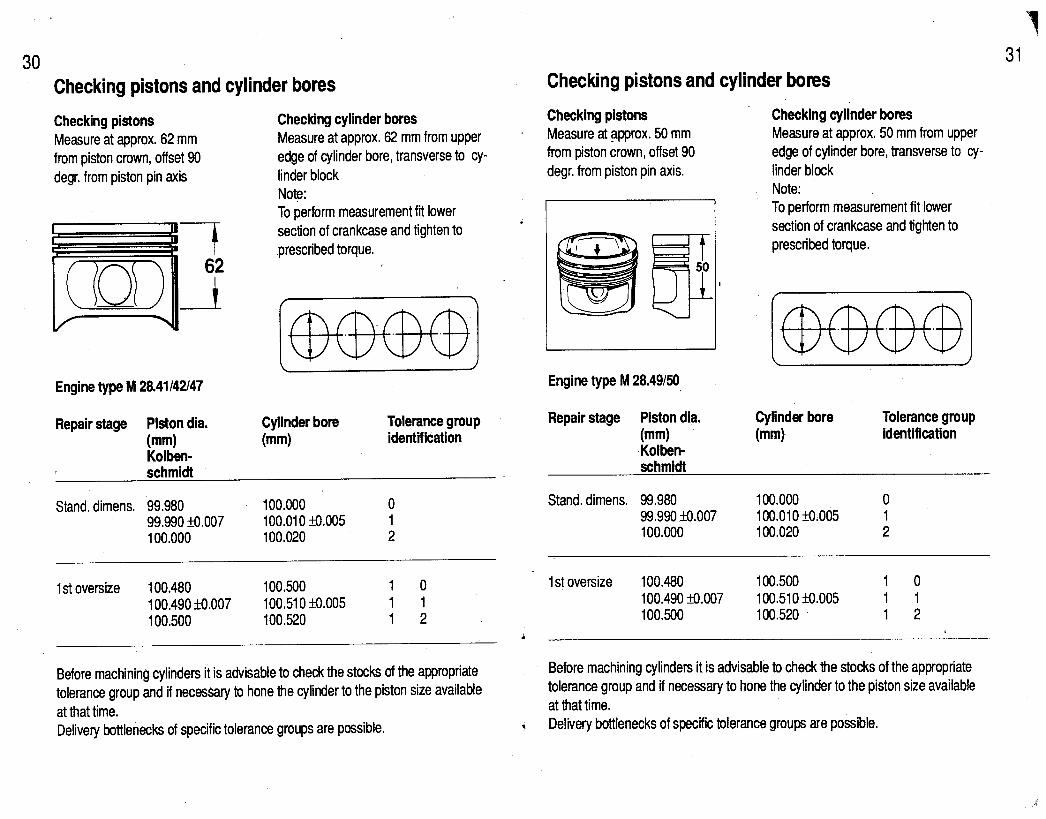
30 Checking pistons and cylinder bores
Checking pistons Measure at approx. 62 mm from piston crown, offset 90 degr. from piston pin axis
Checking cylinder bores Measure at approx. 62 mm from upper edge of cylinder bore, transverse to cy- linder block Note: To perform measurement fit lower section of crankcase and tighten to prescribed torque.
Engine type M 28.41142147
Repair stage Piston dia. (mm) Kolben-
Cylinder bore Tolerance group (mm) identification
Stand. dimens. 99.980 100.000 0 99.990 &Oo.007 100.010 &0.005 1 100.000 100.020 2
1 st oversize 100.480 100.500 1 0 100.490 +0.007 100.510 I!?XIO5 1 1 100.500 100.520 1 2
Checking pistons and cylinder bores
Checking pistons Measure at approx. 50 mm from piston crown, offset 90 degr. from piston pin axis.
Engine type M 28.49150
Repair stage Piston dia. (mm) Kolben- schmidt
Checking cylinder bores Measure at approx. 50 mm from upper edge of cylinder bore, transverse to cy- linder block Note: To perform measurement fit,lower section of crankcase and tighten to prescribed torque.
Cylinder bore (mm)
Tolerance group identification
Stand. dimens. 99.980 100.000 0 99.990 I8I.007 100.010 fo.005 1 100.000 100.020 2
1 st oversize 100.480 100.500 1 0 100.490 ?0.007 100.510 3l.005 1 1 100.500 100.520 1 2
i
Before machining cylinders it is advisable to check the stocks of the appropriate tolerance group and if necessary to hone the cylinder to the piston size available at that time. Delivery bottlenecks of specific tolerance groups are possible.
Before machining cylinders it is advisable to check the stocks of the appropriate tolerance group and if necessary to hone the cyfinder to the piston size available at that time.
1 Delivery bottlenecks of specific tolerance groups are possible.
..:

,_il----- -____7_1 -_v-m-
.’
32 Survey of pistons (dimensions, weights and compression)
Engine M 28.42/47
worldwide Compression 1 O.O:l Nominal dia. 100.0 mm
Piston weight = 765 g Perm. tolerance = + 4 g
Engine htl28.49150 . .
worldwide Compression 1 O-4:1 Nominal dia. 100.0 mm
Piston weight = 720 g Perm. tolerance = + 4 g
Piston weight tolerances
Pistons and piston pins are paired in accordance with weight selection. Pistons are weighed with their pertinentparts (piston pins, piston rings, snap rings).
Piston pins must always remain assigned to the corresponding piston and must not be interchanged even within one engine set. Observe allocation during disas- sembly and assembly of engine, and mark if necessary.
If piston pins have been interchanged by mistake, reallocation must be carried out by checking the total weights.
Piston and cylinder marking 33
Identification of pistons on piston crown
Identification for cylinders on cylinder block
a - Cylinder designation (assignment) b - Tolerance group
Installation position of pistons With valve pockets of equal size on both sides, the installation position is marked by an arrow pointing towards the belt pulley.
Cylinder designation
Ignition sequence 1-37-2-6-54-8 Only pistons and cylinders of the same tolerance groups may be paired together. Various tolerance groups may ’ be used within one and the same en- gine.
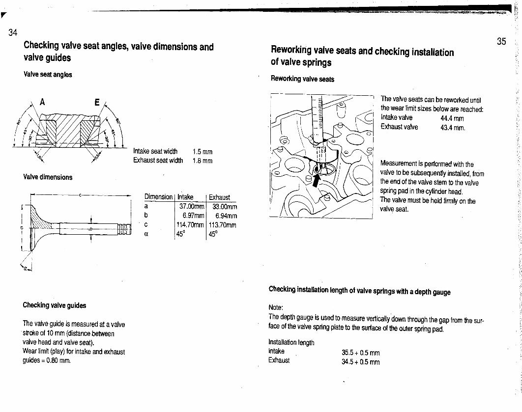
Checking valve seat angles, valve dimensions and valve guides
Reworking valve seats and checking installation
Valve seat angles
of valve springs
Reworking valve seats
Intake seat width 1.5mm Exhaust seat width 1.8 mm
Valve dimensions
Checking valve guides Note:
The valve guide is measured at a valve stroke of 10 mm (distance between valve head and valve seat), Wear limit (play) for intake and exhaust guides = 0.80 mm.
Exhaust 33.00mm 6.94mm
113.70mm 45O ’
Checking installation length of valve springs with a depth gauge
The depth gauge is used to measure vertically down through the gap from the sur- face of the valve spring plate to the surface of the outer spring pad.
Installation length Intake 35.5 t 0.5 mm Exhaust 34.5 t 0.5 mm
The valve seats can be reworked until the wear limit sizes below are reached: Intake valve 44.4 mm Exhaust valve 43.4 mm.
Measurement is performed with the valve to be subsequently installed, from the end of the valve stem to the valve spring pad in the cylinder head. The valve must be held firmly on the valve seat.

36
. . :
- _ -.._ -_ _- -- --- ~---_-_ ~-.ys-v--3=.f-i~~~-~-
;:
Machining the cylinder head mating face
Permissible unevenness of mating face: 0.05 mm Permissible unevenness after machining: 0.03 mm Peak-to-valley height = 0.015 mm
Cylinder head reconditioning size and marking
Size new 147fO.l mm Gasket 1.1 mm Marking none
Size reconditioned Gasket Marking
146.8...146.6 mm 1.4mm N
Size new A = 147 f 0.1 mm Size worn A = 146.6 mm
Marking ,,N“
Apply to dead head beneath gasket surface of cylinder head cover on exhaust side, between cylinders 2 and 3/6 and 7.
Height of letter stamp ,,N” 6 mm
Installing the cylinder head
Cylinder head attached with hex. head bolts
Note The cylinder head can also be fiied with the engine installed. If both cylinder heads are to be removed and installed, it is advisable to remove the engine first.
Tightening sequence:
1
Slackening sequence: reverse order
Tightening specifications for cylinder head
1st stage 2nd stage 3rd stage
Note
20 Nm (15) 90’ turn 9OOturn
When fifing the hex. head bolts and washers, no lubricant must be used. Only the threads of the hex. head bolts must be lightly coated with engine oil.
37

38 Camshaft survey
Engine type
Right camshaft Cylinder bank 1...4 Intake shaft Exhaust shaft
Identification on rear end surface
Left camshaft Cylinder bank 5...8 Intake shaft Exhaust shaft
Identification on rear end surface
Valve timing 1 mm stroke, zero play
Intake opens Intake closes Exhaust opens Exhaust closes
Worldwide Worldwide Worldwide as of Model 90 as of Model 90 as of Model 92
928 S4 928 GT 928 GTS Engine type 928 S4 928 GT 928 GTS M 28.42 M 28.47 M. 28.49150 M 28.42 M 28.47 M. 28.49150
928.105.271 .OO 928.105.271 .Ol 928.105.271.03 928.105.273.00 928.105.273.01 928.105.273.03
271 .OO 271.01 271.03 4 273.00 273.01 273.03
928.105.272.00 928.105.272.01 928.105.272.03 928.105.274.00 928.105.274.01 928.105.274.03
272.00 272.01 272.03 274.00 274.01 274.03
11’ CA after TDC 3’ CA after TDC 13” CA after TDC 36” CA after BDC 42’ CA after BDC 61’ CA after BDC 17” CA before BDC 30” CA before BDC28” CA bef. BDC 2’ CA before TDC 5’ CA before TDC12” CA bef. TDC
Checking camshaft adjustment
Worldwide Worldwide Worldwide As of Model 90 As of Model 90 As of Model 92
Cylinder bank 1...4 Test/adjustment value 1.8fO.l mm 2.8fO.l mm 1.83 + 0.1 mm
Cylinder bank 5...8 Test/adjustment value 2.0 + 0.1 mm 3.1 +O.l mm 2.08 & 0.1 mm
All test/adjustment values measured at 20” CA after overlap TDC.
,
39
. .
. ::
i:

41 40 Adjusting camshaft belts
Engine type M 28.42147149150 Adjustment value: 5.0 t 0.3 scale units
i.
V-belt dimensions
Engine type M 28.42/47/49/50 !
V-belt for alternator (Polyrib) mm K6 858 LW M28.47149
V-belt for alternator (Polyrib) mm K6 872 LW M28.42150 V-belt for servo pump mm 12.5 x. 1000 LA V-belt for AC compressor mm 12.5 x 1125 LA M28.42/47
V-belt for NC compressor mm 12.5 x 1080 LA M28.49150 V-belt for aux. air pump mm 12.5 x 925 FO molded teeth
Checking V-belts Check tension by pressing the middle of the belt with one’s thumb. Belt should give by approx. 10 mm.
Adjusting tension of poly-rib belt for alternator
Adjustment value
New belt: 9.2 scale units Used belt: 8.4 t 0.8 scale units
Coolant mixing table (average values)
Frost protection Antifreeze to -25:C :g*g 4::
50;
Water Antifreeze Water
60% 6.4 I 55%
;*;I %
50% . 8:0 I
Cleaning the Complete Engine Oil System Following Engine Failure (Bearing Failure)
Note This cleaning sequence merely indicates where chips may be found. The actual amount of work involved must be determined separately for each individual case. The following parts should be replaced:
- Hydraulic valve tappets
- Chain tensioner
- Oil filter The following parts should be disman- tled, checked and thoroughly cleaned: - Oil pump - Thermostat housing - Bypass valve - Pressure relief valve - Oil restraining valve in cylinder head
The following parts must be thoroughly cleaned or flushed sev- eral times: Note All oil bores can be flushed thoroughly with conventional benzine. - Oil pan - Oil inlet pipe - Crankcase - Crankshaft - Cylinder heads - Oil lines - Oil filler neck - Oil cooler in radiator
Change oil filter and engine oil after approx. 500 km. Note Following an engine failure the com- plete intake system must be checked for foreign bodies and oil and cleaned be- fore assembly.
. .
‘.
: ‘_
I- /1
‘., ..;

42 Test values for vehicle type 928 S4 - 928 GT - 928 GTS Engine type M 28.42/47/49/50
Test Electric fuel pump delivery quantity
Fuel pressure (engine stopped) Fuel pump relay bridged check value at idle speed Leak test Min. pressure after 20 min
Adjusting idle speed
Idle speed rpm
928 GT version Engine type M 28.4; Idle speed rpm co values %
HC values ppm
Test values min. 1250 crn3/30s
3.8 f 0.2 bar
approx. 3.3 bar
3.0 bar
Without catalytic converter
675 I& 25
775 f 25 0.5...1.5**
I 300
Catalytic converter vehicles
375 3125
775 f 25 1.4...1.2*
5 300’
Special notes
With catalytic converter vehicles an idle speed and CO adjustment is no longer possible
Measured upstream of catalytic converter, lambda sensor plug not disconnected
**On vehicles without catalytic converter, only a CO adjustment is possible. i
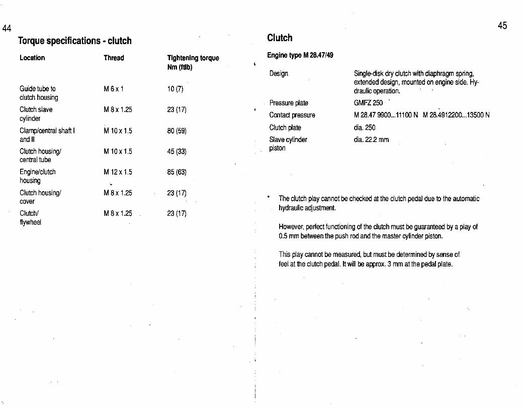
44 Torque specifications - clutch
Location Thread
Guide tube to clutch housing
Clutch slave cylinder
Clamp/central shaft I and II
Clutch housing/ central tube
Engine/clutch housing
Clutch housing/ cover
Clutch/ flywheel
Tightening torque Nm (ftlb)
M6xl 10 (7)
M 8x 1.25 23 (17)
M 10x 1.5 80 (59)
M 10x 1.5 45 (33)
M 12x 1.5 85 (63) L
M 8x 1.25 23 (17)
M 8x 1.25 23 (17)
45 Clutch
Engine type M 28.47149 t
Design Single-disk dry clutch with diaphragm spring, extended design, mounted on engine side. Hy- draulic operation. . i
Pressure plate GMFZ250 - I
Contact pressure M 28.47 9900...11100 N M 28.4912200...13500 N
Clutch plate dia. 250
Slave cylinder dia. 22.2 mm piston
* The clutch play cannot be checked at the clutch pedal due to the automatic hydraulic adjustment.
However, perfect functioning of the clutch must be guaranteed by a play of 0.5 mm between the push rod and the master cylinder piston.
This play cannot be measured, but must be determined by sense of feel at the clutch pedal. It will be approx. 3 mm at the pedal plate.

46 Torque specifications - manual transmission, shift actuation and central tube
Location Thread
Central tube/transmission
Securing nut/ drive pinion
Bearing cover/ transmission case
Plug/locks
Upper cover/ transmission case
Reverse gear lock plate/ upper cover
Ring gear bolt Side cover/ transmission case
Rear cover/ transmission case
Oil filling and drain plug
Clamping sleeve/ drive shaft
Reversing lamp switch
Joint flange/trans- mission output
Bearing body/inner- shift rod
M 10x 1.5
M32x1.5
M 8x 1.25
M 12x 1.5
M6xl
M6xl
M 12x1.25 M 8x 1.25
M 8x 1.25
M 24 x 1.5
M 10x 1.5
M 18x 1.5
MlOx1.5.
M8x1.25
Tightening torque Nm (ftlb)
58 (43)
300 (221)
30 (22)
20 (15)
10 (7) 16 (12)
10 (7)
165 (122) 22 (16)
22 (16)
22 (16)
80 (59)
22 (16)
43 (32)
15 (11)
Torque specifications - manual transmission, shift actuation and central tube
t Location
Transmission mount/ transmission case
# Central tube/ clutch housing
Shift rod/bearing body (Shift rod coupling)
Angled joint/ guide tube
Bracket mount for guide tube to body/ central tube
Cap and hex. head nut to threaded bolt for preselection fields
Thread Tightening torque Nm (ftlb)
M 12x 1.5 85 (63)
M 10x 1.5 43 (32)
M8x1.25 25 (18)
BM 10 25 (18)
M6xl 10 (7)
M14xl 50 (37)
47
,-

48
:I
f.
j
49 5-speed manual transmission G 28.55
General data
Design
Ratios*
1 st gear
2nd gear
3rd gear
4th gear
5th gear
Reverse
Final drive
Final drive ratio
Tracsmission oil
Filling capacity
Manual transmission Type G 28.55
Direct transmission with intermediate gear 1
Ti J-2 it iht it x iht T2:Tl 3222
17 1 44 1 2.5882 Il.4545 13.7645 1
22 38 1.7272 1.4545 2.5122
26 32 1.2307 1.4545 1.7900
29 27 0,931o 1,4545 1,354l
Direct 1 .OOOO Direct 1.0000
22 (30) 2.2727 1.4545 3.3056 (30) 50
Bevel gear differential without hypoid offset
11:30 i = 2.7272
Multigrade transmission oil SAE 75 W 90 API classification GL 5 (or MIL-L 2105 B)
Approx. 4.5 liters
TI = No. of teeth on first gear wheel in power flow of respective gear
T2 = No. of teeth on second gear wheel in power flow of respective gear
it = Gear ratio
il,,t = Intermediate gear ratio
5-speed manual transmission G 28.57
TI = No. of teeth on first gear wheel in power flow of respective gear
TZ = No. of teeth on second gear wheel in power flow of respective gear
it = Gear ratio
ilnt = Intermediate gear ratio

50 Torque specifications - automatic transmission
Location
Primary pump to front cover
Screw plug (torque converter)
Front cover to transmission case
Support flange to transmission case
Screw plug (counter-bearing brake band B 1)
Detent plate to range selection shaft
Leaf spring to transmission case
Starter interlock and reversing light switch to transmission case
Range selector lever to shaft
Secondary pump to transmission case
Nut for shaft of governor axial mounting
Thread
M8
MlOxl
M8
M6
M27x1.5
M6
M6
M6
M6
M6
M6
-.
Tightening torque Nm (ftlb)
20 (15)
14(10)
13 (10)
11 (8) .
70 (52) .
8 (6)
8 (6)
8 (6)
8 (6)
8 03
6 (4)
Torque specifications .- automatic ttinsmission
Location
Lower cover with reinforcement panel
Lower cover compl. to transmission case
Screw plug (modul- ating, governor, working pressure measurement point)
Bolt (vacuum box bracket)
Kick-down solenoid valve .
Facing plate to slide valve case
Facing plate to mounting housing
Mounting housing to slide valve case
Slide valve case to transmission
ATF filter to lower cover
Thread
M5
M6
M8xl
M6
M 14x 1.5
M4
M4
M5
M6
M5
Tightening torque Nm (ftlb)
4 (3)
8 (6)
13 (10)
8 (6)
20 (15)
3.3 (2.4)
3.3 (2.4)
0.15
8 (6)
4 (3)
I’ +. .i 51 ‘-:
:

f
52 53 Torque specifications - automatic transmission 40speed automatic transmission A 28.16118
Location Thread
Screw plug (ATF pan)
ATF pan to transmission case
Front torque con- verter case to trans- mission case
Driver plate to torque converter
Rear transmission case to transmission case
Bearing assembly to rear transmission case
Final drive to transmission case
Collar nut (drive pinion)
ATF filler pipe to ATF pan
ATF reservoir to ATF pan
Tightening torque Nm (ftlb)
MlOxl 14 (10)
M8 8 (6)
M8 23 (17)
M8 46 (34)
Ml0 42 (31)
M8 33 (24)
M 10 46 (34) M 10 46 (34)
M26x1.5
M 24
380 (280) A 28.16 450 (332) A 28.18
78 (58)
M6 6 (4)
/ I
/ /
j I
I
I !
!
General data A 28.16118
Design fully-automatic 4-speed planetary transmission
Ratios 1st gear 2nd gear 3rd gear 4th gear Reverse gear
3.87 2.25 1.44 1 .oo 5.59
Final drive Bevel gear differential without hypoid offset
Final drive ratio 13 : 33 i = 2.538
Stall speed A28.16 1750...2150 rpm
Capacity (final drive)
Capacity Automatic part with torque converter
A.28;18 2150-400 rpm
A 28.16 approx. 3.0 I A 28.18 approx. 1.9 I Hypoid transmission oil API classification GL5 (MIL - L 2105 B) SAE 90
Automatic part with torque converter approx. 7.3 I ATF - Dexron II D

54 Pressure spec. in bar overpressure as of Model 90 Shift points in km/h
Test pressure
Modulating pressure*
Working pressure
Governor pressure
Transmission type A28.16 A 26.18
4.2 + 0.05 4.4 f 0.05
16.0f 1 15.8 F 1
approx 0.2 0.45 at 20 km/h approx. 1 .l 1.40 at 50 km/h approx. 2.J 2.15 at lOO’km/h approx. 2.7 3.10 at 150 km/h
Measuring conditions
ATF temperature approx 8O’C, se- lector lever in position D, driving speed approx. 140 km/h, vacuum line on modulating pressure box disconnected
ATF temperature approx. 80X, selector lever in position D, en- gine running at 1400 rpm, hand- brake engaged and service brake operated. Do not test for longer than 5 seconds, vaccuum line on modulating pressure box discon- nected
Selector lever in position D, vehicle moving in part- load range, vacuum line on modula- ting pressure box disconnected -
*Note
If local conditions do not permit testing at approx. 140 km/h, the test can also be performed at 50 km/h.
I
I
1 I
/
I
/
I
1
I
Transmission type Transmission type A 28.16 A 28.18
Accelerator pedal position km/h km/h km/h km/h
Selector lever position A v A v
Full throttle %I” 1-2-1 41...50 3O.a.23 41...50 30...24
Full throffle “D” 2-3-2 102...117 49...43 102...117 49...43
Full throttle “D” 3-4-3 169...188 144...128 169...188 144...128
Full throttle “2” l-2 53.m.58 - 53.a.58 -
Note: All speeds are approximate values
Symbols: A Upshift V I Downshift
-,
55
.i
,’
i> : 1,.
,’
:
/ :..
i-
.;: I

56 Torque specifications
Location
Upper control arm to body
Lower control arm to body at rear
Lower control arm to body at front
Protective bar to side member
McPherson strut to body
McPherson strut and stabilizer sus- pension to lower control arm
Stabilizer clip to side member
Stabilizer suspen- sion to stabilizer
Upper and lower control arms to steering knuckle
Protective panel to steering knuckle
Wiring retainer to steering knuckle
Brake caliper to steering knuckle
- front axle
Thread
M 14x 1.5
M 12x 1.5
M 12x 1.5
M 10
Ml0
M 12x 1.5
M 10
M 12x 1.5
M 12x 1.5
M7 /
15 (11) 1
M7 15 (11)
M 12x 1.5 85 (63) ! I
57
Torque specifications - front axle
Tightening torque Nm (ftlb)
Location
i
140 (103) Brake disk to wheel hub
120 (88)
85 (63)
46 (34) -
46 (34)
85 (63)
46 (34)
i Fillister head screw to clamping nut
Wheel to wheel hub
Track rod to steering arm
Rubber bearing on piston rod of McPherson strut
Ball joint (joint carrier) to lower control arm
Supporting ring on pivoting axle (upper control arm)
85 (63) I ,
65 (48) I !
Thread
M6
M7
M 14x 1.5
M 12x 1.5
M 12x 1.5
M 12x 1.5
M 12x 1.5
Tightening torque Nm (ftlb)
10 (7)
15 (11)
130 (96)
65 (48)
60 (44) ’
120 (88)
65 (63)

. .
58 Torque specifications - steering
Location
Steering gear to engine carrier
Track rod to steering arm
Universal joint to steering gear
Track rod to ball joint
Steering tie rod to steering rack
Universal joints to steering and universal shafts
Pressure and return lines to steering gear
Steering wheel to steering shaft
Stabilizer clip to side member
V-belt pulley to servo pump
Steering guard to body
Ring hose nipple for suction hose to servo pump
Thread
Ml0
M 12x1.5
M8
M 14x 1.5
M 16x 1.5
M8
M 14x 1.5
M 18x1.5
Ml0
M 14x 1.5
M 6 with 4 mm hex. sock- et bolt M 6 with 5 mm hex. socket bolt
M 18x 1.5
Tightening torque Nm (Mb)
46 (34)
65 (48)
28 (21)
45 (33)
150 (111)
28 (21)
30 (22) I
50 (37)
46 (34) I
50 (37) I !
9.7 (7.1) I I I
12 (9)
60 (44)
59 Torque specifications - rear axle
Location
Cross member to body
Light-alloy cast part (mounting) for lower control arm (as of Mod. 86) to body
Lower control arm to cross member (camber eccentric)
Lower control arm to body (toe eccentric)
Brake caliper to wheel carrier
Wheel carrier to lower control arm
Upper control arm to cross member, upper control arm to wheel carrier
Universal/rear wheel shaft to wheel hub
Universal shaft to transmission and drive shaft
Wheel to wheel hub McPherson strut to body
Stabilizer bearing to body
Thread
Ml0
Ml0
M 14x 1.5
M 12x 1.5
M 12x 1.5
M 14x 1.5
Ml0
M22x 1.5
Ml0
M 14x 1.5 Ml0
Ml0
ightening torque Nm (ftlb)
46 (34)
46 (34)
200 (147)
120 (88)
85 (63)
140 (103)
46 (34)
460 (339)
81 (60)
130 (96) 46 (34)
46 (34)

60 Torque specifications - rear axle
Location
Stabilizer suspension to lower control arm
Stabilizer suspension to stabilizer
Bearing pivot to lower control arm
Rubber bearing on piston rod (McPherson strut)
Transmission bearing to rear axle cross member
Speed sensor to wheel carrier
Retaining bracket to wheel carrier.
Retaining bracket to cross member
Guard plate to wheel carrier
Thread
Ml0
Ml0
M 12x1.5
M 12x1.5
M 12x 1.5
M6
M6
M6
M8 M6
Tightening torque Nm (ftlb)
46 (34)
46 (34)
85 (63)
58 (43)
85 (63)
10 (7)
10 (7)
6 (4)
23 (17) 10 (7)
Technical data - front axle, steering and rear axle
Front axle
Wheel suspension Independent suspension, double control arm with coil spring and shock absorber located inboard
Springs
Shock absorbers
Stabilizer
Steering .
Steering wheel dia.
Steering wheel ratio (mean value)
Rear axle
Wheel suspension
Springs
Shock absorbers
Stabilizer
1 coil spring per wheel
Double-acting shock absorbers
dia. 28 x 4 mm (tubular stabilizer)
Rack and pinion steering with track rods, hydraulicaly assisted - power steering
380 mm
17.75:l
Independent suspension with lower diagonal control arm and upper transverse control arm, coil spring and shock absorber located inboard
1 coil spring per wheel
Double-acting hydraulic shock absorbers
dia. 22.5 x 3.5 mm (tubular stabilizer)

62 Wheel alignment adjustment values*
The following values apply to curb weight in accordance with DIN 76020 (car with full fuel tank, spare wheel and tool kit).
Adjustment values and tolerance
Front axle Height adjustment: From wheel contact area to 190 - 20 mm** measurement surface on rear control arm bearing
Toe - unpressed
Toe difference angle,at 20’ lock :
t 15’+5’
-1 “t20’
Camber
Caster
-3OYzlO’
Mod. 90 3”30’+30’*** as of Mod. 91 4’+1’***
Rear axle Height adjustment: From wheel contact area to measurement surface on cross member
173+10mm**
Toe per wheel
Camber
+10’&5
-4o’&lO’
Max. difference left to riaht
10mm
may be affected only replacement by of steering arms
10’
20’ 20’
10mm
* Adjustment values for wheel alignment are only valid for actual vehicle height (see Rep. Manual page 44-l).
** The height adjustment values apply to new vehicles. Used vehicles may be up to 10 mm lower, i.e., the tolerance towards ,,tbo low“ may deviate by 10 mm. However, this must then be the case for both axles.
** The caster value of 4”tl’ can be set retroactively on Model ‘90 vehicles.
Torque specifications - mech. brake system
Ldcation
Fillister head screw to clamping nut
Brake cafiper to steering knuckle
Brake caliper to wheel carrier
Brake disk to wheel hub
Guard plate to steering knuckle
Handbrake locking segment to bearing bracket
Universal shaftI rear wheel shaft to wheel hub
Wheel to wheel hub
Locking segment to handbrake lever
Guard plate to wheel carrier
Speed sensor to wheel carrier and steering knuckle
Thread
M7 15 (11)
M 12x 1.5 85 (63)
M 12x 1.5 85 (63)
M6 10 (7)
M7 15 (11)
M8 25 (18)
M22x1.5 460 (339)
M 14x 1.5
M8
M8 - M6
M6
Tightening torque Nm (ftlb)
130 (96)
23 (17)
23 (17) 10 (7)
10 (7)
! : -_i
63 ”
r’ ?,’ >L i:
:s
I ;- L . .
f

64 Torque specifications - hydi. brake system
Location
Brake booster to bulkhead
Brake line to brake master cylinder, brake hoses, brake power regulator, T-distributor and hydraulic unit. Connecting line to 4-piston fixed caliper,
Brake hose to 4-piston fixed caliper
Rear brake hose to 4-piston fixed caliper
Lock nut to push rod (brake booster)
Bleed screw to 4-piston fixed caliper
Brake master cylinder to vacuum booster
Screw-in regulator to. hydraulic unit .
Hydraulic unit bracket to wheel well
Hydraulic unit to hydraulic unit bracket -
T-distributor to bracket
Thread Tightening torque Nm (ftlb)
M8 23 (17)
MlOxl 12 (9)
MlOxl 16.5 (122)
MlOxl 14 (10)
Ml0 35 (26)
Ml0 8-12 (6-9)
M8 23 (17)
MlOxl 14 (10)
M8
M6
M6
23 (17)
10 (7)
10 (7)
;. 65 /
Technical data - brake system, Mod. 90191
Designation
Brake booster dia. iv
Brake master cylinder dia.
\ front rear
Brake power regulator (screw-in regulator) Changeover pressure Reduction factor .
Brake disk dia. front rear
Effective brake disk dia.
front rear
Piston dia. in brake caliper
front
Dimensions/remarks Wear limit
10 inches 4.5 (inner boost factor)
as of Model 87 with shorter free play (shorter free pedal travel)
Tandem type with 2 central valves 23.81 mm 20.64 mm
18bar 0.46
304 mm 299 mm
250.8 mm 246 mm
per fixed caliper 2x44t2x36mm per fixed caliper 2x30t2x28mm
:.

66 Technical data - brake system, Mod. 90191 Technical data - brake system, Mod. 90191
Designation
Brake lining area per front wheel
Brake lining area per rear wheel
Total lining area
Lining thickness front rear
Brake disk thickness new front rear
Brake disks - min. thick- ness* after reworking front
rear
Max. thickness tolerance of brake disk
Max. lateral runout of brake disk
Max. lateral runout of brake disk in installed condition
Max. peak-@valley height after reworking
Dimensionskemarlts Wear limit
126 cm2
86 cm2
424 cm2
approx. 13 mm approx. 13 mm
32 mm 24 mm
2mm 2mm
30.6 mm- 30 mm 22.6 mm 22mm’
0.02 mm
0.05 mm
0.1 mm
0.006 mm
Designation
Play at brake pedal with brakes bled and engine off (foot brake lever without I stop)
\ Parking brake / (Handbrake)
Handbrake drum dia.
Brake shoe width
Brake lining area per wheel
Brake lining thickness
Dimensions/remarks Wear limit
approx. 10 mm due to preset clearances in brake booster
Drum brake, acting mechanically on both rear wheels
180 mm 181 mm
25 mm
85 cm2
4.5 mm 2mm
* The brake disk must only be reworked symmetrically, i.e. evenly from both sides.
:.
::
67

;8 69 Technical data - brake system as of Mod. 92 Technical data - brake system as of Mod. 92
Designation
Service brake (foot brake)
Brake booster dia. inches Boost factor
Brake master cylinder dia. front dia. rear
Brake-power regulator Changeover pressure Reduction factor
Brake disk dia. ’ front rear
Effective brake disk dia. front rear
Piston dia. in brake caliper front rear
Brake lining area front rear
Remarks, dimensions Wear limit 928 GTS 928 GTS
Hydraulic dual-circuit brake system with front axle/rear axle circuit split. Vacuum brake booster, internally ventilated brake disks with &piston fixed calipers front and rear. The push rod brake circuit is allocated to the front wheels. ABS is standard.
10 4.5
23.81 mm 20.64 mm
18 bar 0.46
322 mm 299 mm
259.6 mm 246 mm
2x44t2x36mm 2x30+,2x28mm
302 cm2 172 cm2
Designation
Total brake lining area
Lining thickness front rear
Brake disk thickness new front rear
Min. brake disk thickness*
after reworking front rear
Max. thickness tolerance of brake disk
Max. lateral runout of brake disk
Max. lateral runout of wheel hub
Max. lateral runout of brake disk in installed condition
Max. peak-to-valley height of brake disk after re- working
Rtiarks, dimensions Wear limit 928GTS , 928 GTS
474 cm2
approx. 12 mm approx. 12 mm
32 mm 24 mm
2mm 2mm
30.6 mm 22.6 mm
0.02 mm
0.05 mm
0.05 mm
0.1 mm
0.006 mm
30.0 mm 22.0 mm

70 Technical data - brake system as of Mod. 92
Designation Remarks, dimensions Wear limit 928 GTS 928 GTS
Push rod play (measured at brake pedal plate)
Parking brake (handbrake)
Handbrake drum dia.
Brake shoe widtf-r
Brake lining thickness
approx. 10 mm”
Drum brake, acting mechaically on both rear wheels
180 mm 181 mm
25 mm
4.5 mm 2mm
* The brake disk must only be reworked symmetrically, i.e. evenly from both sides.
** Normally determined by preset clearances in the brake booster if the footbrake lever remains unsupported.
Wheels and tires / 71
Tire conditiinltire pressure Tires represent safety elements which can only meet the requirements made of them if inflation pressure is correct and if tread depth is sufficient.
The inflation pressures quoted here are minimum pressures. Lower pressures must on no account be used, since they not only diminish handling quality but may also lead to serious tire damage.
Valve caps protect the valve from dust and dirt, and therefore also from leaks. Always tighten caps properly and replace missing caps.
For safety reasons, a check of the tire pressure should also be accompanied by a check to ensure that tread depth is sufficient, that no foreign bodies are embedded in the tire, and that there are no cuts, tears or bumps on the tire’s sidewall (break- age of webbing).
I

72 Tire pressure (summer and winter tires) with tires cold (approx. 2O’C) Survey of tires and wheels/tire specification codes
15 and 164nch tires
front rear
Summer tires* Winter tires
2.5 bar overpressure 2.5 bar overpressure 3.0 bar overpressure** 3.0 bar overpressure
174nch tires
front rear
Summer tires Winter tires
2.5 bar overpressure 2.5 bar overpressure 2.5 bar overpressure 3.0 bar overpressure
Collapsible spare tire front and rear only permitted at front
2.5 bar overpressure wit8 PR 89 P/92 P tires 2.2 bar overpressure with 4 PR 83 P tires
* For “V” and “ZR” tires, amended standards and regulations require tire pressures which deviate from those given in the Driver’s Manual. The new tire inflation pressures quoted above must now be used. Corresponding information stickers are available from every Official Porsche Center.
** In the USA only 2.5 bar (36 psi) is in some cases permissible. This depends on the tires, since earlier tires had lettering on the sidewall which limited the permissible operating pressure of the tire (max. press.) in N. America to 36 psi (2.5 bar). Lettering for 3.0 bar tire pressure = max. press. 44 psi . or 300 Kpa.
The survey of tires and wheels for summer and winter is contained in the Techni- cal Information bulletins (TI), Group 4.
When replacing summer tires the tire specification number must be ob served. The specification codes NO, Nl , and N2 distinguish summer tires spe- cially approved by Porsche from other versions of the same tire type and tire size. The approved tires are also contained in the relevant TI.
NO, Nl and N2 tires, even of the same make, must not be used simultaneously on one and the same vehicle.
Checking Rims
The measuring points for vertical and lateral runout on the inner and outer rim beads are shown in the drawing.
Max, permissible vertical and lateral runout of light-alloy rims = 1 .O mm.
Note
Straightening twisted rims is not permissible.
1. i-
>=
73 .*
.
/.’
i.
I.
:-
.’
;I.
11 .F”
1..
-.- ;I
: p

74 Technical data - air conditioning
Refrigerant volume with addit. air conditioner
Refrigerant oil in AIC compressor
Safety valve on fluid reservoir
950 g refrigerant R 12 1150 g refrigerant R 12
280 f 20 cm3 Densoil 6
The safety valve opens at a pressure of 40 + 5 bar.
As of model 93 refrigerant R 134 a
/
I /
1
I
/
I
I
I
Torque specifications - air conditioning
Location
Compressor intake line
Compressor pressure line
Condenser
Condenser fluid reservoir
Evaporator fluid tank
’ Pressure line expansion valve
Intake line expansion valve
Evaporator expansion valve
lesignation
Jnion nut
Union nut
Union nut
Union nut
Union nut
Retaining screw 5/8” x 18 UNF
Retaining screw 7/8”xl8NS
Retaining screw
Thread
718” x 14UNF
3Mx16UNF
3Wx16UNF
314” x 16 UNF
5Kx18UNF
3Wx18NS
rightening oque 33 Nm (24)
!4 Nm (18)
34 Nm (18)
24 Nm (18)
17 Nm (13)
: 17 Nm (13)
33 N”! (24)
24 Nm (18)
i’
”
75 ;


Weights
Type Model year
Curt, weight to DIN
Perm. total weight
Penn. axle load front’
Penn. axle load rear*
Penn. trailer load unbraked”
Penn. trailer load braked**
Perm. roof load with Porsche rcoi transport system
Perm. drawbar load
Penn. towing weight
I
928 SW928 GT 90191
Europe USA low
rg 1580 kgllbs 159013505
cg 1920 kgllbs 190014189
tg 920 kgllbs 92012028
cg 1100 kgllbs 110012425
tg 750
1(g 1600
kg 35 kgllbs 35i 7i kg 75 kg/lbs 751 16:
kg 75
tg 3520
* The perm. total weight must not however be exceeded. ” Up to 16 % incline
928 GTS 92193
Europa USA ROW
kg 1620
kg 1960
kg 940
kg 1100
kg 750
kg 1600
kg 35 kg 75
kg 75
kg 3560
kg/lbs 163013593
kg/h 1925KJ44
kg/lbs 94012072
kg/lbs 110012425
kg/lbs 35l 77 kgnbs 75 1165
Filling capacities
Engine oil specification
Engine oil volume
Cooling system inc. heating
Power steering
Fuel tank
Brake fluid tank
Windshield washer system with headlamp cleaning system
Intensive cleaning system
Manual transmission with differential
Automatic transmission with torque converter
Final drive
Approved: API SE/SF with combination API SE/CC - SE/CD - SF/CC - SF/CD multigrade oils see works approval, Technical Information bulletins for engine oils
Apprbx. 7.5 I, plus 0.5 I when filter changed (measurement with oil dipstick is decisive crite- rion). Difference between “Min.” and “Max.” marks on dipstick = approx. 1.5 I.
Approx. 16 I coolant, factory filling gives frost pro- tection to -30% (Scandinavian countries to - 40°C). Only use antifreeze and corrosion inhibitors which are suitable for light-alloy engines and radiators.
Approx. 0.7 I hydraulic fluid, only ATF Dexron II
Approx. 86 I, inc. 12 I reserve
Approx. 0.2 I brake fluid in accordance with SAE J 1703 or DOT4
Approx. 7.5 I water
Approx. 0.6 I “Porsche Special Silicone Remover’
Multigrade transmisson oil SAE 75 W 90, API classification GL 5 (or MILL 2105 B) Volume approx. 4.5 I, 928 GTS approx. 4.8 I
Volume approx. 9.3 I Oil-change volume with torque converter approx. 7.3 I ATF Dexron Ii
Volume approx. 3.0 I, 928 GTS approx. 1.9 I API classification GL 5 (MIL-L 2105 B) SAE 90
c :i Ft
79 E
;.
!(:
I. ._
:
I. ‘-7 ;- L:
,- :_ 1.


![Legislative Task Force · 2014-03-10 · lots, no public water or sewer, shallow depth to water table and impervious layer. [ Jt1] na District A: no basements, in-ground swimming](https://img.pdfslide.us/doc/110x75/5ea9ee40edbf7b0dfe2755a7/legislative-task-2014-03-10-lots-no-public-water-or-sewer-shallow-depth-to-water.jpg)