Embed Size (px)
Citation preview
Technical Sealing GuidePORON® Urethane | BISCO® Silicone Materials
TECHNICAL SEALING GUIDE
TABLE OF CONTENTSEnclosures Standards ............................................................................................. 1
Material Specifications .......................................................................................... 6
Materials ................................................................................................................ 8
Cell Structure ......................................................................................................... 9
Sealing .................................................................................................................12
Long-Term Sealing Effectiveness ........................................................................14
Material Selection ................................................................................................17
Gasket Design ......................................................................................................22
Adhesive Systems ................................................................................................24
Gasket Design Expertise ......................................................................................25
Material Selection Expertise ................................................................................25
Click heading to advance to desired page
1
SUCCESSFUL ENCLOSUrES rELy ON ALL ASpECTS OF THE DESIGN TO mAkE AN EFFECTIvE SEAL.
This guide presents comparison test data on sealing materials while highlighting essential criteria for long-term sealing solutions in many enclosure applications.
The accompanying research acts as a reference for material selection, while serving to better educate the market on Rogers’ materials.
ENCLOSUrE STANDArDSSeals are used in industrial, electrical, and electronic applications to keep in what’s meant to be in and keep out what’s meant to be out.
Four types of gaskets – strip, die-cut, form-in-place and bulb extrusion – help to seal according to the requirements of four of the most common standards:
p National Electrical manufacturer’s Association (NEMA): Ratings are numbered from 1 to 12. Most common ratings for indoor applications are 12 and 13 while 3, 4, 4x, 6, and 6P are most common for outdoor applications.
p Underwriters Laboratories® (UL): Ratings are similar to NEMA.
p International Electrotechnical Commission (IEC): IP-XX (ingress protection) codes specify protection required.
p Canadian Standards Association (CSA)
Enclosure standards are important because they directly affect safety and protection, as well as help the purchaser select and obtain the proper product for his needs. They are written as application descriptions and expected performance guidelines.
Some IP ratings allow a certain amount of water to enter an enclosure through a gasket as long as the water does not interfere with the performance of electrical and electronic equipment. NEMA and UL standards differ from IP because in most cases they do not allow any ingress into the enclosure.
2
NEMA Definitions Pertaining to Non-Hazardous Locations
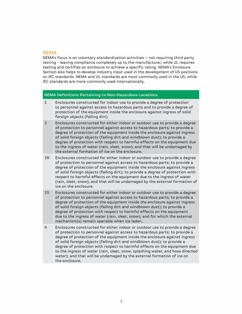
1 Enclosures constructed for indoor use to provide a degree of protection to personnel against access to hazardous parts and to provide a degree of protection of the equipment inside the enclosure against ingress of solid foreign objects (falling dirt).
3 Enclosures constructed for either indoor or outdoor use to provide a degree of protection to personnel against access to hazardous parts; to provide a degree of protection of the equipment inside the enclosure against ingress of solid foreign objects (falling dirt and windblown dust); to provide a degree of protection with respect to harmful effects on the equipment due to the ingress of water (rain, sleet, snow); and that will be undamaged by the external formation of ice on the enclosure.
3R Enclosures constructed for either indoor or outdoor use to provide a degree of protection to personnel against access to hazardous parts; to provide a degree of protection of the equipment inside the enclosure against ingress of solid foreign objects (falling dirt); to provide a degree of protection with respect to harmful effects on the equipment due to the ingress of water (rain, sleet, snow); and that will be undamaged by the external formation of ice on the enclosure.
3S Enclosures constructed for either indoor or outdoor use to provide a degree of protection to personnel against access to hazardous parts; to provide a degree of protection of the equipment inside the enclosure against ingress of solid foreign objects (falling dirt and windblown dust); to provide a degree of protection with respect to harmful effects on the equipment due to the ingress of water (rain, sleet, snow); and for which the external mechanism(s) remain operable when ice laden.
4 Enclosures constructed for either indoor or outdoor use to provide a degree of protection to personnel against access to hazardous parts; to provide a degree of protection of the equipment inside the enclosure against ingress of solid foreign objects (falling dirt and windblown dust); to provide a degree of protection with respect to harmful effects on the equipment due to the ingress of water (rain, sleet, snow, splashing water, and hose directed water); and that will be undamaged by the external formation of ice on the enclosure.
NEmANEMA’s focus is on voluntary standardization activities – not requiring third party testing - leaving compliance completely up to the manufacturer, while UL requires testing and certifies an enclosure to achieve a specific rating. NEMA’s Enclosure Section also helps to develop industry input used in the development of US positions on IEC standards. NEMA and UL standards are most commonly used in the US, while IEC standards are more commonly used internationally.

3
NEMA Definitions Pertaining to Non-Hazardous Locations
4X Enclosures constructed for either indoor or outdoor use to provide a degree of protection to personnel against access to hazardous parts; to provide a degree of protection of the equipment inside the enclosure against ingress of solid foreign objects (windblown dust); to provide a degree of protection with respect to harmful effects on the equipment due to the ingress of water (rain, sleet, snow, splashing water, and hose directed water); that provides an additional level of protection against corrosion; and that will be undamaged by the external formation of ice on the enclosure.
6 Enclosures constructed for either indoor or outdoor use to provide a degree of protection to personnel against access to hazardous parts; to provide a degree of protection of the equipment inside the enclosure against ingress of solid foreign objects (falling dirt); to provide a degree of protection with respect to harmful effects on the equipment due to the ingress of water (hose directed water and the entry of water during occasional temporary submersion at a limited depth); and that will be undamaged by the external formation of ice on the enclosure.
6P Enclosures constructed for either indoor or outdoor use to provide a degree of protection to personnel against access to hazardous parts; to provide a degree of protection of the equipment inside the enclosure against ingress of solid foreign objects (falling dirt); to provide a degree of protection with respect to harmful effects on the equipment due to the ingress of water (hose directed water and the entry of water during prolonged submersion at a limited depth); that provides an additional level of protection against corrosion; and that will be undamaged by the external formation of ice on the enclosure.
12 Enclosures constructed (without knockouts) for indoor use to provide a degree of protection to personnel against access to hazardous parts; to provide a degree of protection of the equipment inside the enclosure against ingress of solid foreign objects (falling dirt and circulating dust, lint, fibers, and flyings); and to provide a degree of protection with respect to harmful effects on the equipment due to the ingress of water (dripping and light splashing).
12K Enclosures constructed (with knockouts) for indoor use to provide a degree of protection to personnel against access to hazardous parts; to provide a degree of protection of the equipment inside the enclosure against ingress of solid foreign objects (falling dirt and circulating dust, lint, fibers, and flyings); and to provide a degree of protection with respect to harmful effects on the equipment due to the ingress of water (dripping and light splashing).
UL uses similar standard designations to NEMA: UL Type 4 = NEMA 4Copyright ©2012 NEMA. All rights reserved. Reprinted with permission of the National Electrical Manufacturers Association.
4
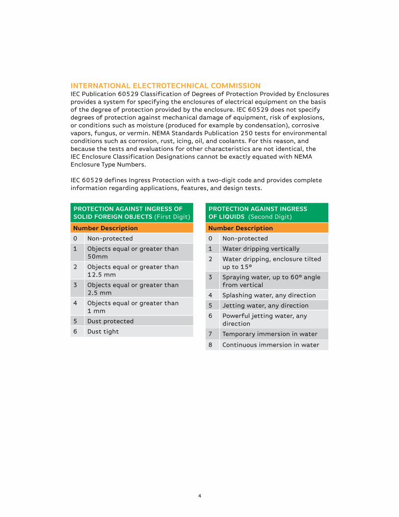
INTErNATIONAL ELECTrOTECHNICAL COmmISSIONIEC Publication 60529 Classification of Degrees of Protection Provided by Enclosures provides a system for specifying the enclosures of electrical equipment on the basis of the degree of protection provided by the enclosure. IEC 60529 does not specify degrees of protection against mechanical damage of equipment, risk of explosions, or conditions such as moisture (produced for example by condensation), corrosive vapors, fungus, or vermin. NEMA Standards Publication 250 tests for environmental conditions such as corrosion, rust, icing, oil, and coolants. For this reason, and because the tests and evaluations for other characteristics are not identical, the IEC Enclosure Classification Designations cannot be exactly equated with NEMA Enclosure Type Numbers.
IEC 60529 defines Ingress Protection with a two-digit code and provides complete information regarding applications, features, and design tests.
prOTECTION AGAINST INGrESS OF SOLID FOrEIGN OBjECTS (First Digit)
Number Description
0 Non-protected
1 Objects equal or greater than 50mm
2 Objects equal or greater than 12.5 mm
3 Objects equal or greater than 2.5 mm
4 Objects equal or greater than 1 mm
5 Dust protected
6 Dust tight
prOTECTION AGAINST INGrESS OF LIqUIDS (Second Digit)
Number Description
0 Non-protected
1 Water dripping vertically
2 Water dripping, enclosure tilted up to 15°
3 Spraying water, up to 60° angle from vertical
4 Splashing water, any direction
5 Jetting water, any direction
6 Powerful jetting water, any direction
7 Temporary immersion in water
8 Continuous immersion in water
5
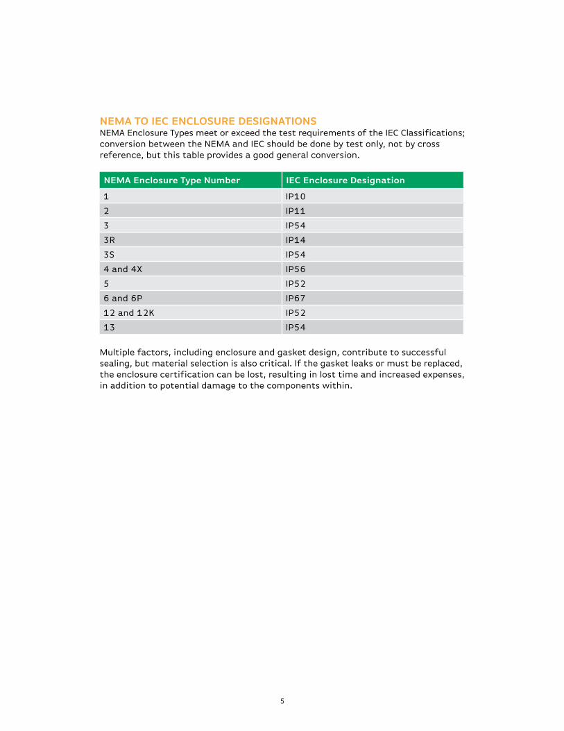
NEmA Enclosure Type Number IEC Enclosure Designation
1 IP10
2 IP11
3 IP54
3R IP14
3S IP54
4 and 4X IP56
5 IP52
6 and 6P IP67
12 and 12K IP52
13 IP54
NEmA TO IEC ENCLOSUrE DESIGNATIONSNEMA Enclosure Types meet or exceed the test requirements of the IEC Classifications; conversion between the NEMA and IEC should be done by test only, not by cross reference, but this table provides a good general conversion.
Multiple factors, including enclosure and gasket design, contribute to successful sealing, but material selection is also critical. If the gasket leaks or must be replaced, the enclosure certification can be lost, resulting in lost time and increased expenses, in addition to potential damage to the components within.
6
mATErIAL SpECIFICATIONS
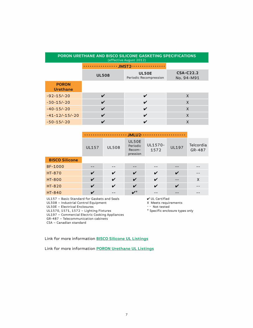
Many engineers prefer to use gasketing materials like PORON® Urethanes and BISCO® Silicones that are already certified for use under several standards, including UL-508 (industrial control equipment), UL-1572 (HID lighting fixtures), and especially UL-50E (electrical enclosures), with testing done to the new periodic recompression standard. These certifications enable designers to consider gasket materials without testing the material itself, effectively simplifying the screening process.
UL-50E is the most common standard, as electrical enclosures are the most prevalent. This certification can be given not only to enclosures, but to gasketing materials as well. These materials receive one of two ratings.
1. Continuous Compression – Tests include tensile and elongation retention after exposure to 70°C. Dimensional changes after oil immersion are also evaluated.
2. periodic recompression – In addition to Continuous Compression (above), a compression set test is cycled at room temperature, 70°C and -30°C. Impact testing is also performed (-30°C only).
Periodic Recompression testing best simulates what most gaskets experience in field applications – compression cycling at varying temperatures. This is true of door gaskets that see compression cycling over time.
7
pOrON UrETHANE AND BISCO SILICONE GASkETING SpECIFICATIONS(effective August 2012)
• • • • • • • • • • • • • • • • jmST2• • • • • • • • • • • • • • • •
UL508 UL50EPeriodic Recompression
CSA-C22.2No. 94-M91
pOrON Urethane
-92-15/-20 4 4 X
-30-15/-20 4 4 X
-40-15/-20 4 4 X
-41-12/-15/-20 4 4 X
-50-15/-20 4 4 X
• • • • • • • • • • • • • • • • • • • • jmLU2• • • • • • • • • • • • • • • • • • • • •
UL157 UL508
UL50EPeriodic Recom-pression
UL1570-1572
UL197TelcordiaGR-487
BISCO Silicone
BF-1000 -- -- -- -- -- --
HT-870 4 4 4 4 4 --
HT-800 4 4 4 4 -- X
HT-820 4 4 4 4 4 --
HT-840 4 -- 4* -- -- --
UL157 – Basic Standard for Gaskets and SealsUL508 – Industrial Control EquipmentUL50E – Electrical EnclosuresUL1570, 1571, 1572 – Lighting FixturesUL197 – Commercial Electric Cooking AppliancesGR-487 – Telecommunication cabinetsCSA – Canadian standard
4 UL CertifiedX Meets requirements– – Not tested* Specific enclosure types only
Link for more information BISCO Silicone UL Listings
Link for more information pOrON Urethane UL Listings
8
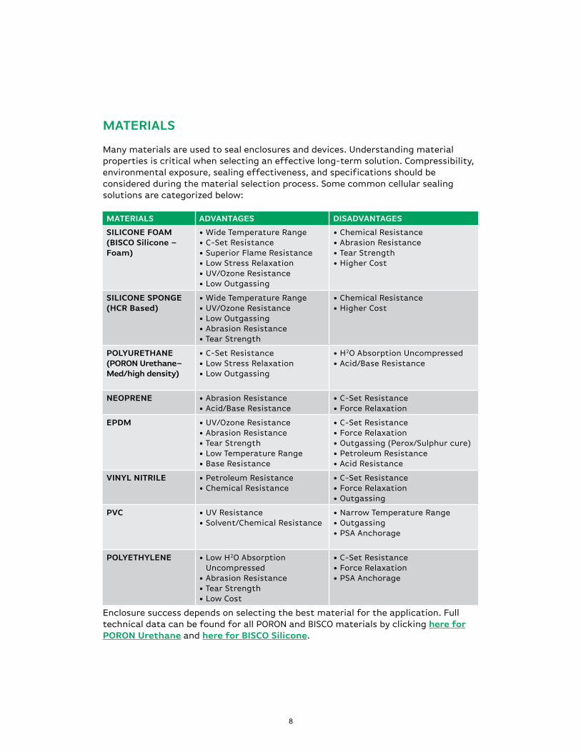
mATErIALS
Many materials are used to seal enclosures and devices. Understanding material properties is critical when selecting an effective long-term solution. Compressibility, environmental exposure, sealing effectiveness, and specifications should be considered during the material selection process. Some common cellular sealing solutions are categorized below:
mATErIALS ADvANTAGES DISADvANTAGES
SILICONE FOAm(BISCO Silicone – Foam)
• Wide Temperature Range• C-Set Resistance• Superior Flame Resistance• Low Stress Relaxation• UV/Ozone Resistance• Low Outgassing
• Chemical Resistance• Abrasion Resistance• Tear Strength • Higher Cost
SILICONE SpONGE(HCr Based)
• Wide Temperature Range• UV/Ozone Resistance• Low Outgassing• Abrasion Resistance• Tear Strength
• Chemical Resistance • Higher Cost
pOLyUrETHANE(pOrON Urethane– med/high density)
• C-Set Resistance• Low Stress Relaxation • Low Outgassing
• H2O Absorption Uncompressed• Acid/Base Resistance
NEOprENE • Abrasion Resistance• Acid/Base Resistance
• C-Set Resistance• Force Relaxation
EpDm • UV/Ozone Resistance• Abrasion Resistance• Tear Strength• Low Temperature Range• Base Resistance
• C-Set Resistance• Force Relaxation• Outgassing (Perox/Sulphur cure)• Petroleum Resistance• Acid Resistance
vINyL NITrILE • Petroleum Resistance• Chemical Resistance
• C-Set Resistance• Force Relaxation• Outgassing
pvC • UV Resistance• Solvent/Chemical Resistance
• Narrow Temperature Range• Outgassing• PSA Anchorage
pOLyETHyLENE • Low H2O Absorption Uncompressed
• Abrasion Resistance• Tear Strength• Low Cost
• C-Set Resistance• Force Relaxation• PSA Anchorage
Enclosure success depends on selecting the best material for the application. Full technical data can be found for all PORON and BISCO materials by clicking here for pOrON Urethane and here for BISCO Silicone.
9
CELL STrUCTUrE
A material’s sealing effectiveness should be based on performance, not on its open or closed cell structure. When a microcellular open-cell gasket is compressed, the cell wall openings will effectively “close off,” improving the sealing properties of that material.
ASTM D1056 defines “Open” and “Closed” cell:
Open Cell – A product whose cells are not totally enclosed by its walls and open to the surface, either directly, or by interconnecting with other cells.
Closed Cell – A product whose cells are totally enclosed by its walls and hence not interconnecting with other cells.
Additionally, not all cellular materials are comprised of 100% open or 100% closed cells. It’s very common to have a blend of open and closed cells. Understanding the advantages and disadvantages of each is important.
Open-cell materials typically resist compression set and force relaxation better than closed-cell materials, but are not as effective at resisting water absorption in an uncompressed state. However, at a certain level of compression the small openings in the cell walls of an open-cell foam will “close off,” resulting in an effective seal.
WHEN LEFT UNCOmprESSEDOpen cells in an uncompressed state can be infiltrated by liquids and gases. These cells can promote absorption and usually release that absorbed air or moisture over time. Common applications for open-cell materials include cleaning sponges, thermal insulation, filters, acoustic absorption, shock and vibration management, and cushioning.
Closed cells in an uncompressed state contain pockets of gas enclosed in an elastomeric “shell.” Common applications for closed-cell materials include floats requiring good buoyancy, wet suits, and water resistant crafts and toys.
When it comes to liquid or gas absorption, cell structure plays an important role. The cell voids in an open-cell material can vary significantly. Open-cell foams can be reticulated, meaning there are more open voids than wall structures, giving the appearance of cell striations. Even under compression, the reticulated structure will not “close off” unless compressed to a solid mass. PORON Urethane and BISCO Silicone cell voids will “close off” at lower levels of compression, resulting in a seal while the material is still in a fairly low range of compression force deflection.
10
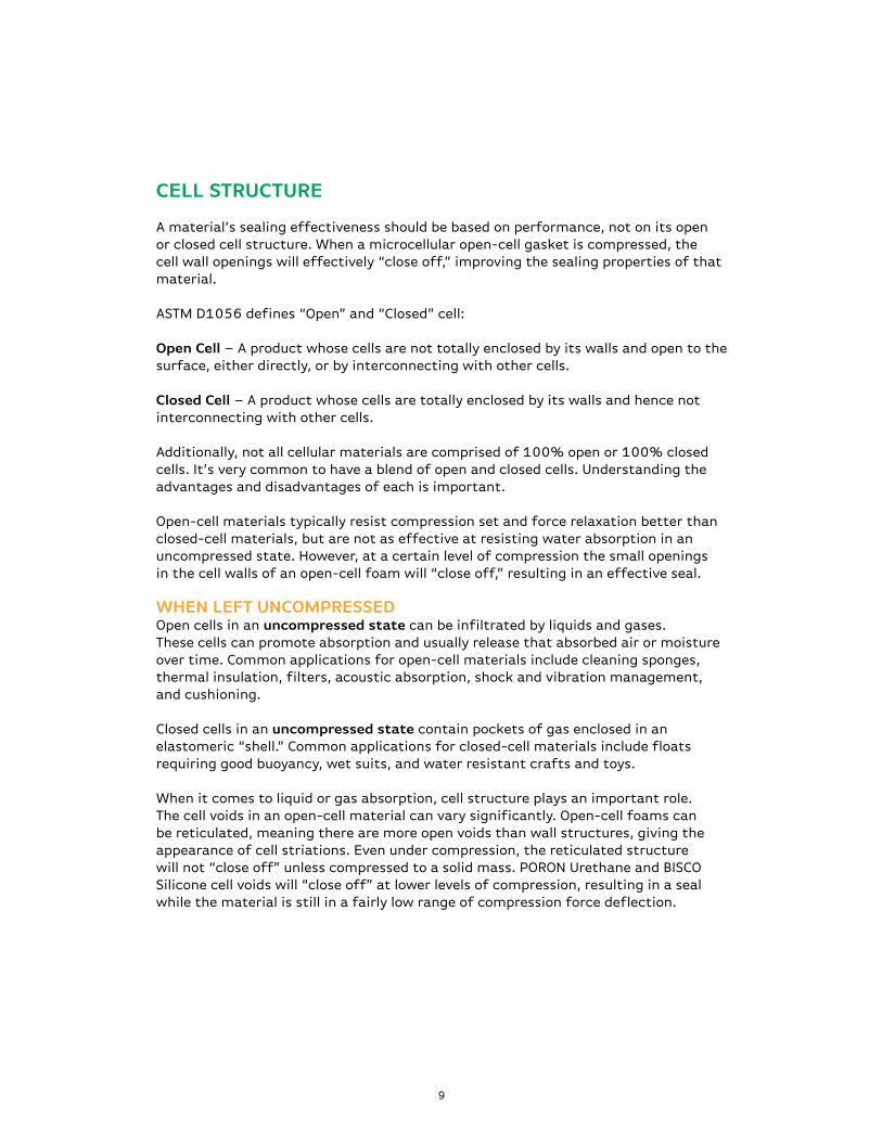
WHEN COmprESSEDForce deflection can also be affected by cell structure. Materials with a high percentage of closed cells typically depend on gases inside the cells to provide force resistance just as a tennis ball depends on air trapped inside to bounce. Once that cell (or ball) is ruptured, the deflection or bounce is reduced significantly. The cell becomes more susceptible to taking a compression set. These gases also tend to diffuse through the cell walls over time, reducing the long-term force deflection of the material.
Open-cell materials allow gases to flow freely between the cells during compression cycles. The cell walls are not dependent on the pressure within allowing the compression deflection to be a function of the elastomeric spring forces. Unlike closed cell materials, open cell materials typically resist compression set more effectively, as they do not depend on the gases to provide force.
One exception can be closed cell silicones. Silicone chemistry typically offers good elastomeric pushback regardless of an open or closed cell structure.
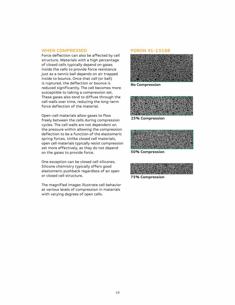
The magnified images illustrate cell behavior at various levels of compression in materials with varying degrees of open cells.
25% Compression
PORON 41-15188
No Compression
50% Compression
75% Compression
11
EpDm
25% Compression25% Compression
BISCO HT-800
No Compression No Compression
50% Compression 50% Compression
75% Compression 75% Compression
12
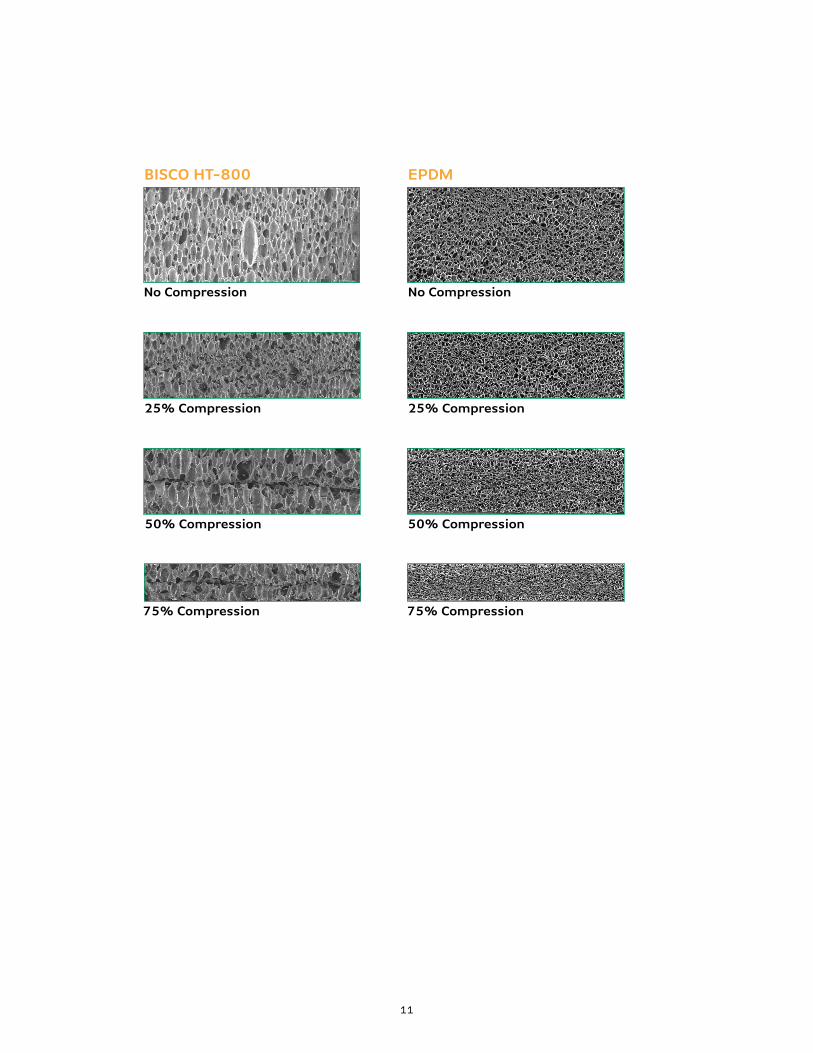
SEALING
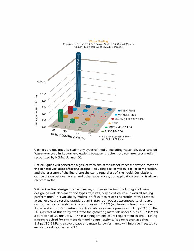
Through an extensive water sealing study, many materials were evaluated for initial sealing effectiveness. A high-demand scenario was simulated with 1.5 psi/10 kPa of water pressure on a 0.250”/6.35 mm wide gasket using materials of medium firmness compressed to various compressions.
A gasket material’s sealing performance is tested using water as the medium of infiltration. Water, often regarded as the most difficult fluid to seal against, provides a good indication of a seal’s performance with other mediums despite there being no definitive correlation with these other mediums (liquid or gas). Rogers’ testing, outlined below, is valuable as a comparative study.
TESTING prOCEDUrE Equipment: Based on the design per ASTM F37 (Test Method B). This standard sealability test for gasket materials provides guidance for testing sealing performance by measuring a material’s leakage rate.
Samples: Donut-shaped gaskets
Sample Dimensions: Gasket widths of 0.25”/6.35 mm and 0.5”/12.70 mm. Material thickness of 0.125”/3.17 mm, 0.188”/4.77 mm, 0.25”/6.35 mm.
procedure: Gaskets are compressed between two flat surfaces while pressurized water is forced from the center through the cross-section of the gasket. Water is pressurized using compressed air and is controlled per test requirements. Pressures of 0 (only atmospheric pressure), 1.0 psi/6.9 kPa and 1.5 psi/10.3 kPa were tested.
measurements/Findings: The leakage rate is measured as displacement in the column holding the pressurized water. Leakage is calculated in mL/min.
13
Gaskets are designed to seal many types of media, including water, air, dust, and oil. Water was used in Rogers’ evaluations because it is the most common test media recognized by NEMA, UL and IEC.
Not all liquids will penetrate a gasket with the same effectiveness; however, most of the general variables affecting sealing, including gasket width, gasket compression, and the pressure of the liquid, are the same regardless of the liquid. Correlations can be drawn between water and other substances, but application testing is always recommended.
Within the final design of an enclosure, numerous factors, including enclosure design, gasket placement and types of joints, play a critical role in overall sealing performance. This variability makes it difficult to relate the results of this test to actual enclosure testing standards (IP, NEMA, UL). Rogers attempted to simulate conditions in this study per the parameters of IP X7 (enclosure submersion under 1m of water for 30 minutes), which simulates a gauge pressure of 1.5 psi/10.3 kPa. Thus, as part of this study, we tested the gasketing materials under 1.5 psi/10.3 kPa for a duration of 30 minutes. IP X7 is a stringent enclosure requirement in the IP rating system required for the most demanding applications. Rogers recognizes that 1.5 psi/10.3 kPa is a severe case and material performance will improve if tested to enclosure ratings below IP X7.
LEA
KA
GE
RA
TE (
ml/
min
)
GASKET COMPRESSION (%)
2.0
4.0
6.0
8.0
10.0
>100.0
0.010
3050
70
>1
00
.0
(1) 41-15188 Gasket thickness: 0.188 in (4.775 mm)
BISCO HT-800
PORON 41-15188
EPDM
BLEND (NEOPRENE/EPDM)
NEOPRENE
VINYL NITRILE
Water SealingPressure: 1.5 psi/10.3 kPa / Gasket Width: 0.250 in/6.35 mm
Gasket Thickness: 0.125 in/3.175 mm (1)
14
LONG-TERM SEALING EFFECTIVENESS
Stress relaxation and compression set resistance are two key attributes that significantly impact long-term performance.
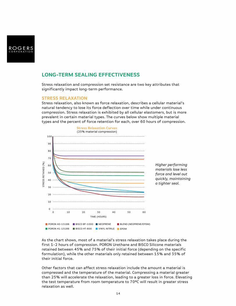
STrESS rELAXATIONStress relaxation, also known as force relaxation, describes a cellular material’s natural tendency to lose its force deflection over time while under continuous compression. Stress relaxation is exhibited by all cellular elastomers, but is more prevalent in certain material types. The curves below show multiple material types and the percent of force retention for each, over 60 hours of compression.
As the chart shows, most of a material’s stress relaxation takes place during the first 1-2 hours of compression. PORON Urethane and BISCO Silicone materials retained between 45% and 75% of their initial force (depending on the specific formulation), while the other materials only retained between 15% and 35% of their initial force.
Other factors that can affect stress relaxation include the amount a material is compressed and the temperature of the material. Compressing a material greater than 25% will accelerate the relaxation, leading to a greater loss in force. Elevating the test temperature from room temperature to 70°C will result in greater stress relaxation as well.
Higher performing materials lose less force and level out quickly, maintaining a tighter seal.
10
20
30
40
50
60
70
80
90
100
00
10 20 30 40 50 60
STR
ESS R
ETA
INE
D (
%)
TIME (HOURS)
BISCO BF-1000
BISCO HT-800
PORON 40-15188
PORON 41-15188 EPDM
NEOPRENE
VINYL NITRILE
BLEND (NEOPRENE/EPDM)
Stress relaxation Curves(25% material compression)
15
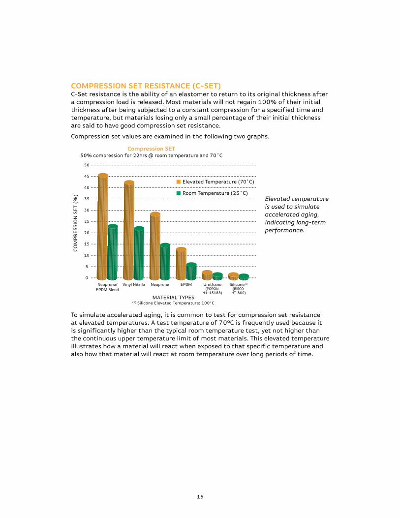
COMPRESSION SET RESISTANCE (C-SET)C-Set resistance is the ability of an elastomer to return to its original thickness after a compression load is released. Most materials will not regain 100% of their initial thickness after being subjected to a constant compression for a specified time and temperature, but materials losing only a small percentage of their initial thickness are said to have good compression set resistance.
Compression set values are examined in the following two graphs.
To simulate accelerated aging, it is common to test for compression set resistance at elevated temperatures. A test temperature of 70°C is frequently used because it is significantly higher than the typical room temperature test, yet not higher than the continuous upper temperature limit of most materials. This elevated temperature illustrates how a material will react when exposed to that specific temperature and also how that material will react at room temperature over long periods of time.
CO
MP
RE
SSIO
N S
ET
(%)
5
10
15
20
25
30
35
40
45
50
0
MATERIAL TYPES(1) Silicone Elevated Temperature: 100̊ C
Room Temperature (23˚C)
Elevated Temperature (70̊ C)
Urethane(PORON
41-15188)
Silicone(1)
(BISCO HT-800)
EPDMNeopreneVinyl NitrileNeoprene/EPDM Blend
Elevated temperature is used to simulate accelerated aging, indicating long-term performance.
Compression SET50% compression for 22hrs @ room temperature and 70˚C
16
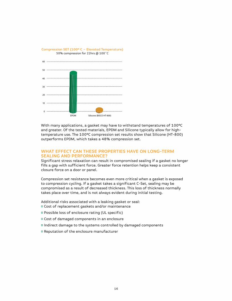
With many applications, a gasket may have to withstand temperatures of 100°C and greater. Of the tested materials, EPDM and Silicone typically allow for high-temperature use. The 100°C compression set results show that Silicone (HT-800) outperforms EPDM, which takes a 48% compression set.
WHAT EFFECT CAN THESE PROPERTIES HAVE ON LONG-TERM SEALING AND pErFOrmANCE?Significant stress relaxation can result in compromised sealing if a gasket no longer fills a gap with sufficient force. Greater force retention helps keep a consistent closure force on a door or panel.
Compression set resistance becomes even more critical when a gasket is exposed to compression cycling. If a gasket takes a significant C-Set, sealing may be compromised as a result of decreased thickness. This loss of thickness normally takes place over time, and is not always evident during initial testing.
Additional risks associated with a leaking gasket or seal:p Cost of replacement gaskets and/or maintenance
p Possible loss of enclosure rating (UL specific)
p Cost of damaged components in an enclosure
p Indirect damage to the systems controlled by damaged components
p Reputation of the enclosure manufacturer
EPDM Silicone (BISCO HT-800)
20
10
30
40
50
60
0
Compression SET (100º C – Elevated Temperature)50% compression for 22hrs @ 100˚C
17
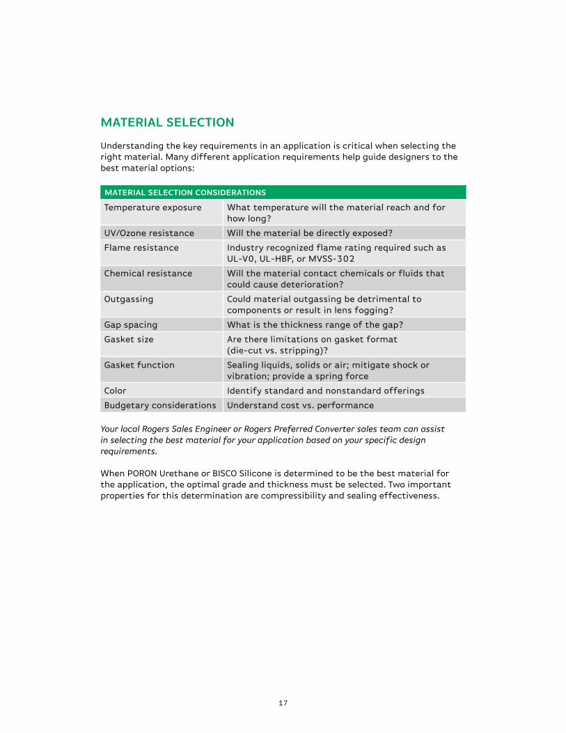
mATErIAL SELECTION
Understanding the key requirements in an application is critical when selecting the right material. Many different application requirements help guide designers to the best material options:
mATErIAL SELECTION CONSIDErATIONS
Temperature exposure What temperature will the material reach and for how long?
UV/Ozone resistance Will the material be directly exposed?
Flame resistance Industry recognized flame rating required such as UL-V0, UL-HBF, or MVSS-302
Chemical resistance Will the material contact chemicals or fluids that could cause deterioration?
Outgassing Could material outgassing be detrimental to components or result in lens fogging?
Gap spacing What is the thickness range of the gap?
Gasket size Are there limitations on gasket format (die-cut vs. stripping)?
Gasket function Sealing liquids, solids or air; mitigate shock or vibration; provide a spring force
Color Identify standard and nonstandard offerings
Budgetary considerations Understand cost vs. performance
Your local Rogers Sales Engineer or Rogers Preferred Converter sales team can assist in selecting the best material for your application based on your specific design requirements.
When PORON Urethane or BISCO Silicone is determined to be the best material for the application, the optimal grade and thickness must be selected. Two important properties for this determination are compressibility and sealing effectiveness.
18
100 20 30 40 50 60
CF
D (
psi
)
CF
D (k
Pa
)
MATERIAL COMPRESSION (%)
41-15250
50-15250
40-15250
92-15250
30-15250
10 20 30 40 50 60
CF
D (
psi
)
CF
D (k
Pa
)
MATERIAL COMPRESSION (%)
HT-820
HT-840
HT-800
BF-1000
HT-870
0
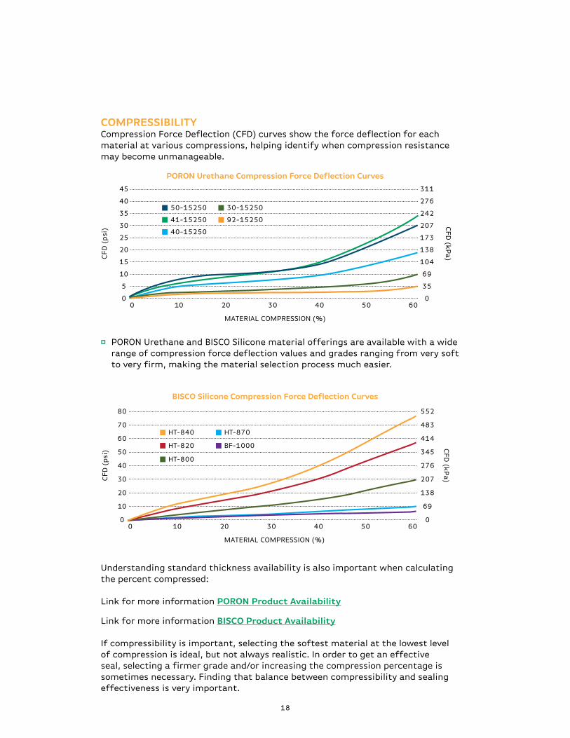
COmprESSIBILITyCompression Force Deflection (CFD) curves show the force deflection for each material at various compressions, helping identify when compression resistance may become unmanageable.
p PORON Urethane and BISCO Silicone material offerings are available with a wide range of compression force deflection values and grades ranging from very soft to very firm, making the material selection process much easier.
PORON Urethane Compression Force Deflection Curves
BISCO Silicone Compression Force Deflection Curves
Understanding standard thickness availability is also important when calculating the percent compressed:
Link for more information pOrON product Availability
Link for more information BISCO product Availability
If compressibility is important, selecting the softest material at the lowest level of compression is ideal, but not always realistic. In order to get an effective seal, selecting a firmer grade and/or increasing the compression percentage is sometimes necessary. Finding that balance between compressibility and sealing effectiveness is very important.
19
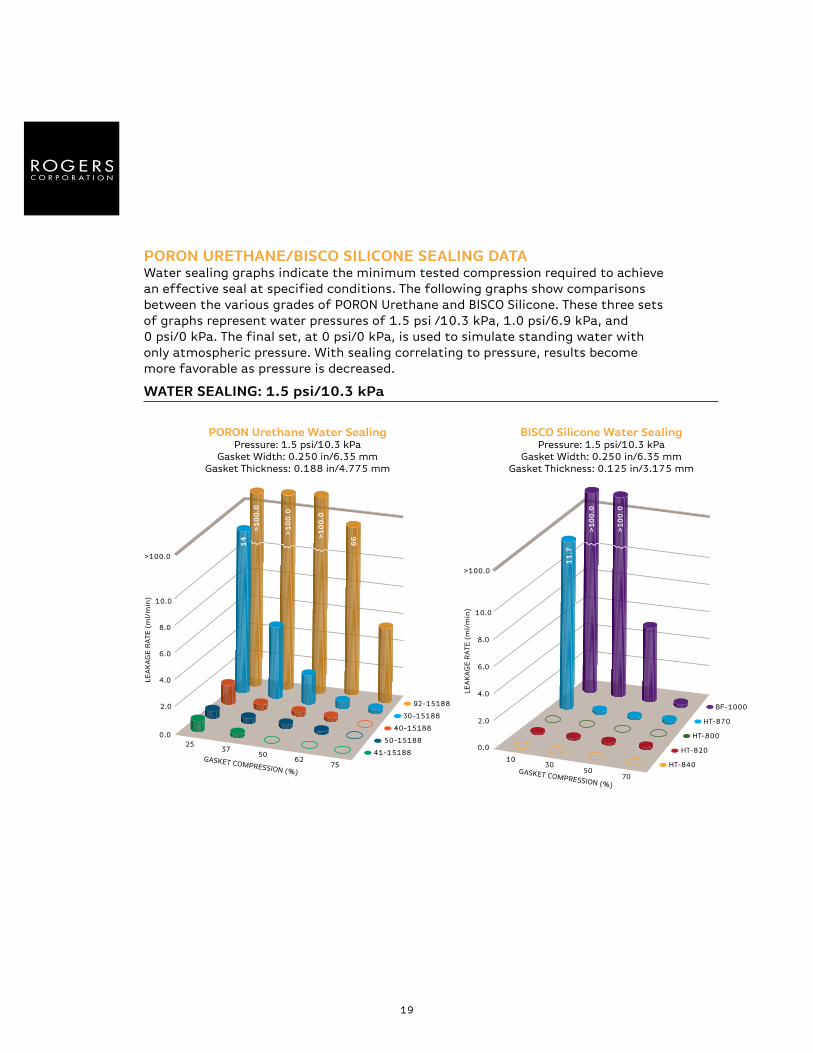
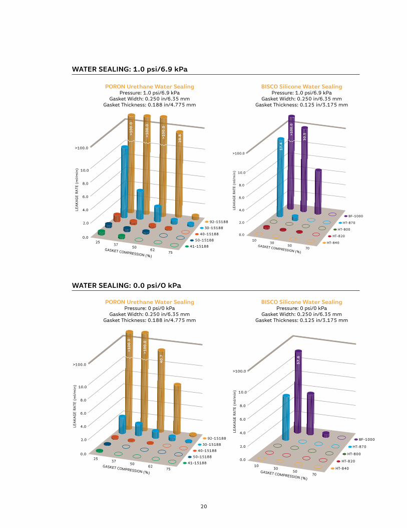
pOrON UrETHANE/BISCO SILICONE SEALING DATAWater sealing graphs indicate the minimum tested compression required to achieve an effective seal at specified conditions. The following graphs show comparisons between the various grades of PORON Urethane and BISCO Silicone. These three sets of graphs represent water pressures of 1.5 psi /10.3 kPa, 1.0 psi/6.9 kPa, and 0 psi/0 kPa. The final set, at 0 psi/0 kPa, is used to simulate standing water with only atmospheric pressure. With sealing correlating to pressure, results become more favorable as pressure is decreased.
PORON URETHANE WATER SEALINGPressure: 1.5 psi (10.3 kPa)/Gasket Width: 0.250 in (6.35 mm)
Gasket Thickness: 0.188 in (4.775 mm)
LEA
KA
GE
RA
TE (
ml/
min
)
GASKET COMPRESSION (%)
2.0
4.0
6.0
8.0
10.0
>100.0
0.025
3750
6275
>1
00
.0
>1
00
.0
>1
00
.0
66
14
41-15188
50-15188
40-15188
30-15188
92-15188
LEA
KA
GE
RA
TE (
ml/
min
)
GASKET COMPRESSION (%)
2.0
4.0
6.0
8.0
10.0
>100.0
0.0
1030
5070
HT-840
HT-820
HT-800
HT-870
BF-1000
>1
00
.0
>1
00
.0
11
.7
pOrON Urethane Water SealingPressure: 1.5 psi/10.3 kPa
Gasket Width: 0.250 in/6.35 mmGasket Thickness: 0.188 in/4.775 mm
BISCO Silicone Water SealingPressure: 1.5 psi/10.3 kPa
Gasket Width: 0.250 in/6.35 mmGasket Thickness: 0.125 in/3.175 mm
WATEr SEALING: 1.5 psi/10.3 kpa
20
PORON URETHANE WATER SEALINGPressure: 1.0 psi (6.9 kPa)/Gasket Width: 0.250 in (6.35 mm)
Gasket Thickness: 0.188 in (4.775 mm)
LEA
KA
GE
RA
TE (
ml/
min
)
GASKET COMPRESSION (%)
2.0
4.0
6.0
8.0
10.0
>100.0
0.025
3750
6275
>1
00
.0
>1
00
.0
>1
00
.0
29
.8
41-15188
50-15188
40-15188
30-15188
92-15188
PORON URETHANE WATER SEALINGPressure: 0 psi (0 kPa)/Gasket Width: 0.250 in (6.35 mm)
Gasket Thickness: 0.188 in (4.775 mm)
LEA
KA
GE
RA
TE (
ml/
min
)
GASKET COMPRESSION (%)
2.0
4.0
6.0
8.0
10.0
>100.0
0.025
3750
6275
>1
00
.0
>1
00
.0
40
.7
41-15188
50-15188
40-15188
30-15188
92-15188
BISCO SILICONE WATER SEALINGPressure: 1.0 psi (6.9 kPa)/Gasket Width: 0.250 in (6.35 mm)
Gasket Thickness: 0.125 in (3.175 mm)
LEA
KA
GE
RA
TE (
ml/
min
)
GASKET COMPRESSION (%)
2.0
4.0
6.0
8.0
10.0
>100.0
0.0
1030
5070
HT-840
HT-820
HT-800
HT-870
BF-1000
>1
00
.0
30
.5
17
.4
BISCO SILICONE WATER SEALINGPressure: 0 psi (0 kPa)/Gasket Width: 0.250 in (6.35 mm)
Gasket Thickness: 0.125 in (3.175 mm)
LEA
KA
GE
RA
TE (
ml/
min
)
GASKET COMPRESSION (%)
2.0
4.0
6.0
8.0
10.0
>100.0
0.0
1030
5070
HT-840
HT-820
HT-800
HT-870
BF-1000
57
.6
pOrON Urethane Water SealingPressure: 1.0 psi/6.9 kPa
Gasket Width: 0.250 in/6.35 mmGasket Thickness: 0.188 in/4.775 mm
pOrON Urethane Water SealingPressure: 0 psi/0 kPa
Gasket Width: 0.250 in/6.35 mmGasket Thickness: 0.188 in/4.775 mm
BISCO Silicone Water SealingPressure: 1.0 psi/6.9 kPa
Gasket Width: 0.250 in/6.35 mmGasket Thickness: 0.125 in/3.175 mm
BISCO Silicone Water SealingPressure: 0 psi/0 kPa
Gasket Width: 0.250 in/6.35 mmGasket Thickness: 0.125 in/3.175 mm
WATEr SEALING: 1.0 psi/6.9 kpa
WATEr SEALING: 0.0 psi/O kpa
21
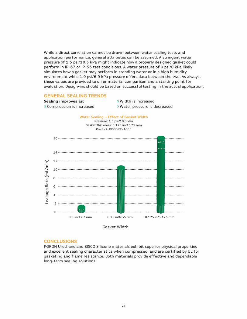
While a direct correlation cannot be drawn between water sealing tests and application performance, general attributes can be assumed. A stringent water pressure of 1.5 psi/10.3 kPa might indicate how a properly designed gasket could perform in IP-67 or IP-56 test conditions. A water pressure of 0 psi/0 kPa likely simulates how a gasket may perform in standing water or in a high humidity environment while 1.0 psi/6.9 kPa pressure offers data between the two. As always, these values are provided to offer material comparison and a starting point for evaluation. Design-ins should be based on successful testing in the actual application.
GENErAL SEALING TrENDSSealing improves as: p Width is increased p Compression is increased p Water pressure is decreased
CONCLUSIONSPORON Urethane and BISCO Silicone materials exhibit superior physical properties and excellent sealing characteristics when compressed, and are certified by UL for gasketing and flame resistance. Both materials provide effective and dependable long-term sealing solutions.
Lea
ka
ge
Ra
te (
mL/
min
)
2
4
6
8
10
12
14
50
0
Gasket Width
0.125 in/3.175 mm0.25 in/6.35 mm0.5 in/12.7 mm
47.3
Water Sealing – Effect of Gasket WidthPressure: 1.5 psi/10.3 kPa
Gasket Thickness: 0.125 in/3.175 mmProduct: BISCO BF-1000
22
GASkET DESIGN
Gasket design in an enclosure is as critical in forming a good seal as the gasketing material itself. Design will have a significant effect on functionality, aesthetics, and overall performance. Common gasketing types include:
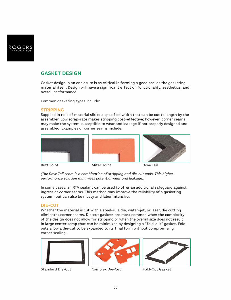
STrIppINGSupplied in rolls of material slit to a specified width that can be cut to length by the assembler. Low scrap-rate makes stripping cost-effective; however, corner seams may make the system susceptible to wear and leakage if not properly designed and assembled. Examples of corner seams include:
(The Dove Tail seam is a combination of stripping and die-cut ends. This higher performance solution minimizes potential wear and leakage.)
In some cases, an RTV sealant can be used to offer an additional safeguard against ingress at corner seams. This method may improve the reliability of a gasketing system, but can also be messy and labor intensive.
DIE-CUTWhether the material is cut with a steel-rule die, water-jet, or laser, die cutting eliminates corner seams. Die-cut gaskets are most common when the complexity of the design does not allow for stripping or when the overall size does not result in large center scrap that can be minimized by designing a “fold-out” gasket. Fold-outs allow a die-cut to be expanded to its final form without compromising corner sealing.
Dove Tail
Fold-Out Gasket
Miter Joint
Complex Die-Cut
Butt Joint
Standard Die-Cut
23
FORM-IN-PLACEDispensing equipment is used to apply an elastomer in liquid form directly into a device or enclosure. This liquid then foams and cures at room temperature. Form-in-place, typically inexpensive to apply, is most beneficial when the gasket design is very complex or would result in significant yield loss with a die-cut. Available foam chemistries are very limited (mainly polyurethane), and the initial cost of the dispensing system is high.
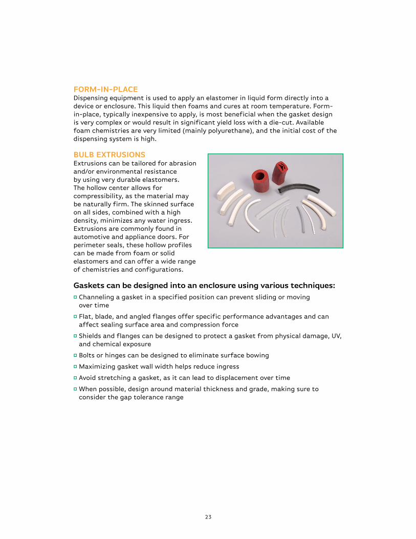
BULB EXTrUSIONS Extrusions can be tailored for abrasion and/or environmental resistance by using very durable elastomers. The hollow center allows for compressibility, as the material may be naturally firm. The skinned surface on all sides, combined with a high density, minimizes any water ingress. Extrusions are commonly found in automotive and appliance doors. For perimeter seals, these hollow profiles can be made from foam or solid elastomers and can offer a wide range of chemistries and configurations.
Gaskets can be designed into an enclosure using various techniques:p Channeling a gasket in a specified position can prevent sliding or moving
over time
p Flat, blade, and angled flanges offer specific performance advantages and can affect sealing surface area and compression force
p Shields and flanges can be designed to protect a gasket from physical damage, UV, and chemical exposure
p Bolts or hinges can be designed to eliminate surface bowing
p Maximizing gasket wall width helps reduce ingress
p Avoid stretching a gasket, as it can lead to displacement over time
p When possible, design around material thickness and grade, making sure to consider the gap tolerance range
24
ADHESIvE SySTEmSAdhesives are commonly used in conjunction with gaskets and seals. Whether the purpose is to form a structural bond, act as a manufacturing aid, or improve the sealing performance of an irregular surface, choosing the best adhesive system for an application is important.
prESSUrE SENSITIvE ADHESIvES (pSAS) PSAs are the most common adhesive types for gaskets. Typically supplied on the gasket, the assembler then removes a release liner to press-fit the gasket in place.
Available PSA chemistries include:
p Acrylic – Adheres well to most gasketing materials and surfaces while offering a good operating temperature range (-50°F/-46ºC to +350°F/+177ºC intermittent).
p Silicone – Adheres well to silicone elastomers and fair to other surfaces. Silicone adhesives offer the widest operating temperature range (-80°F/-62ºC to +450°F/+232ºC), but are also the highest cost.
p Rubber based – For general use applications, typically lower performance and lower cost. Typical intermittent operating temperature range of (+50°F/10ºC to +150°F/10ºC).
Some PSAs are produced on a support carrier, which offers dimensional stability. This helps reduce or eliminate gasket stretching during manufacturing and assembly, while aiding in the removal of kiss cut gaskets from a release liner.
Key considerations when selecting a PSA type include:
p Adhesion properties – to the gasket and mating surface
p Temperature capabilities – cold and heat exposure
p Chemical compatibility
p UV resistance
p Special properties – electrically/thermally conductive, flame retardant
p Cost
25
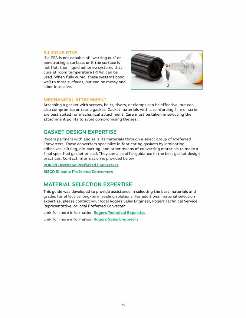
SILICONE rTvS If a PSA is not capable of “wetting out” or penetrating a surface, or if the surface is not flat, then liquid adhesive systems that cure at room temperature (RTVs) can be used. When fully cured, these systems bond well to most surfaces, but can be messy and labor intensive.
mECHANICAL ATTACHmENT Attaching a gasket with screws, bolts, rivets, or clamps can be effective, but can also compromise or tear a gasket. Gasket materials with a reinforcing film or scrim are best suited for mechanical attachment. Care must be taken in selecting the attachment points to avoid compromising the seal.
GASkET DESIGN EXpErTISERogers partners with and sells its materials through a select group of Preferred Converters. These converters specialize in fabricating gaskets by laminating adhesives, slitting, die-cutting, and other means of converting materials to make a final specified gasket or seal. They can also offer guidance in the best gasket design practices. Contact information is provided below
pOrON Urethane preferred Converters
BISCO Silicone preferred Converters
mATErIAL SELECTION EXpErTISEThis guide was developed to provide assistance in selecting the best materials and grades for effective long-term sealing solutions. For additional material selection expertise, please contact your local Rogers Sales Engineer, Rogers Technical Service Representative, or local Preferred Converter.
Link for more information rogers Technical Expertise
Link for more information rogers Sales Engineers
WOrLD CLASS pErFOrmANCE
Rogers Corporation (NYSE:ROG) is a global technology leader in specialty materials and components that enable high performance and reliability of consumer electronics, power electronics, mass transit, clean technology, and telecommunications infrastructure. With more than 180 years of materials science and process engineering knowledge, Rogers provides product designers with solutions to their most demanding challenges. Rogers’ products include advanced circuit materials for wireless infrastructure, power amplifiers, radar systems, high speed digital; power electronics for high-voltage rail traction, hybrid-electric vehicles, wind and solar power conversion; and high performance foams for sealing and energy management in smart phones, aircraft and rail interiors, automobiles and apparel; and other advanced materials for diverse markets including defense and consumer products. Headquartered in Connecticut (USA), Rogers operates manufacturing facilities in the United States, Belgium, China, Germany, and South Korea, with joint ventures and sales offices worldwide.
For more information visit www.rogerscorp.com/hpf
High Performance Foam DivisionsWoodstock, CT, USACarol Stream, IL, USA
Tel: 607.786.8112Fax: 607.786.8120Toll Free: 800.935.2940E-mail: [email protected]
The Woodstock, CT and Carol Stream, IL facilities are Registered to ISO 9001:2008
The information contained in this Technical Guide is intended to assist you in designing with Rogers PORON Urethanes and BISCO Silicones. It is not intended to and does not create any warranties, express or implied, including any warranty of merchantability or fitness for a particular purpose or that the results shown in this Technical Guide will be achieved by a user for a particular purpose. The user should determine the suitability of Rogers PORON Urethanes and BISCO Silicones for each application.
The Rogers logo, The world runs better with Rogers., PORON and BISCO are licensed trademarks of Rogers Corporation. © 2011, 2012 Rogers Corporation. All rights reserved. 0912-PDF. Publication #17-250