Embed Size (px)
Citation preview
1
CURRICULUM
Technical School Leaving Certificate
Electrical Engineering (Pre-SLC Program)
Council for Technical Education and Vocational Training
CURRICULUM DEVELOPMENT DIVISION Sanothimi, Bhaktapur
Developed In 1991, 1st Revision on 1995, 2nd Revision on 2007
Third Revision on July 2014
1989
2
Table of Contents
Introduction: ............................................................................................................................... 3
Aim of the Course: ..................................................................................................................... 3
Overall Objective: ...................................................................................................................... 3
Specific Objectives: ................................................................................................................... 3
Course Description: ................................................................................................................... 3
Course Duration ......................................................................................................................... 4
Evaluation Scheme..................................................................................................................... 5
Eligibility for Admission ........................................................................................................... 5
Admission Criteria ..................................................................................................................... 5
Pattern of Attendance ................................................................................................................. 5
Grading System .......................................................................................................................... 5
Certification ............................................................................................................................... 5
Career Path ................................................................................................................................. 6
First year ................................................................................................................................... 9
Applied English ....................................................................................................................... 10
Jofjxfl/s g]kfnL ............................................................................................................................ 12 Applied Math I ......................................................................................................................... 14
Mechanical Work ..................................................................................................................... 15
Domestic Electrical Installation ............................................................................................... 26 Repair & Maintenance of EA .................................................................................................. 45 Engineering Drawing I ............................................................................................................. 57
Electrical Engineering I ........................................................................................................... 73
Workshop Technology ............................................................................................................. 77
Computer I ............................................................................................................................... 82
Second Year ............................................................................................................................ 90 Industrial Electrical Installation ............................................................................................... 91
Motor Installation and Control System .................................................................................. 109 Repair & Maintenance of EA & WM .................................................................................... 117 Overhead and Underground Line Installation ........................................................................ 133 Basic Electronics .................................................................................................................... 140
Engineering Drawing II - Auto CAD..................................................................................... 150 Electrical Engineering II ........................................................................................................ 199
Workshop Technology II ....................................................................................................... 201 Electrical Machine II.............................................................................................................. 203
Electrical Applied Math II ..................................................................................................... 206
Entrepreneurship Development ............................................................................................. 208 Basic Requirement: ................................................................................................................ 210
3
Introduction:
The competency based and market oriented Curriculum for TSLC in Electrical Engineering is designed to
produce competent skillful work force equipped with knowledge, skills and attitudes. This curriculum
focuses on the basic electrical works to contribute in the national streamline of the use of electrical
engineering equipment, repair and maintenance of electrical devices used in the country. At the same time,
this curriculum aims at offering ample of opportunities for employment in the related sector, mainly
entrepreneurship development of the graduates as well as the employment in the national and international
job market.
Aim of the Course:
The aim of the course is to produce competent human resources in the electrical engineering field who will be able to provide services in different communities as well as in the national & international job markets.
Overall Objective: At the end of the course, the graduates will be able to support in providing the electrical installation,
electrical fault finding and repair and maintenance services in individual household, public sectors as well as
national and international job market.
Specific Objectives:
After the completion of the course the graduates will be able to:
• Install basic electricity • Perform basic electrical functions • Repair and maintain electrical devices • Repair and maintenance of electrical equipment • Operate basic computer applications • Perform designing in computer (Auto CAD) • Find fault in refrigeration & air conditioning system • Repair and maintain faults of electrical system • Assemble /disassemble compressor • Install window and split type air conditioning • Familiarize with electrical, electrical and electronics components related with electrical system • Familiarize with basic computer and computerized drawing system
Course Description:
The world is using many electrical appliances and equipment. We cannot imagine the world without
electrical devices. Even though Nepal is lacking to produce basic level electrical workforce in the country,
especially in the grass-root level of rural and urban communities. Training of this level of electrical
workforce, called TSLC in Electrical Engineering presently becomes one of the major responsibilities of
CTEVT. By doing so, Institute of Engineering can concentrate in preparing higher-level skilled human
resources needed for the country. Thus, with the joint effort by CTEVT and Institute of Engineering, TU and
engineering faculties of all universities of the country together walk to materialize the concept, skill for all.
In this new concept, it will become more necessary or produce a huge number of TSLC in Electrical
Engineering to meet the target of the country without compromising quality of the training. To do so,
4
CTEVT and private training institutions accredited by CTEVT are starting to work for this great challenging
task. In this context a well-developed curriculum is a fundamental pre-requisite for the training program. The
foundation of the curriculum is the results of the DACUM workshop for TSLC in electrical engineering,
conducted in January 2007. The DACUM workshop produces an up-to date list of tasks performed by
workers in Electrical Sub-overseer occupation and provides a valuable insight into what actually
suchoccupation requires. The next phase of developing this curriculum consisted of validating the task lists
with a larger sample of electrical workforce and their users.
Having with the feedbacks after the successful implementation of this curriculum, CTEVT Curriculum
Development Division organized a seminar of subject experts of long experience in the field. The experts
rigorously worked on it and the curriculum is the outcome. It is believed that this revised curriculum of
TSLC in Electrical Engineering will correct all the observed shortcomings.
Mostly the trained graduates are employed in the world of work, national and international electrical
organizations working as a basic level electrical workforce and rest are employed in NGOs and INGOs,
which are working for the development of community of Nepal as well as in the international labour market
and some of them are working as entrepreneurs placing emphasis on the preventive care and repair and
maintenance of electrical devices.
Hence this curriculum is designed to implement in the technical schools under the CTEVT to produce TSLC
graduate in Electrical Engineering in the country. These workforces will be the key persons to provide
preventive care,repairing and maintaining services in the peripheral level.
The candidates for the course are selected from the students who have passed the tenth grade schoolingneed
to go to 29 month training in the training institution including 5 months OJT. However all the candidates
irrespective of their schooling will be required to take an entrance examination to assess their aptitude in the
field. The candidates will be finally selected on the basis of the merit list. The applicants should be
physically sound and mentally matured having not less than 16 years of age. Such students from rural
community might get the preference.
Course Duration
This course will be completed within 29 months/124 weeks/3920 hours; including 20 weeks (800
hours) On the Job Training (OJT) with supervision. The 5 months (800 hours) OJT will be
compulsory after completing the final exam.
5
Evaluation Scheme
a. Regular internal evaluation of the trainees is to be conducted by the related instructors to ensure the proficiency over each task/ skill in each subject.
b. Related technical knowledge of the tasks learnt by the trainees is to be evaluated through the written test. Internal assessment will be conducted 3 times by the institute within the training period.
c. The 80% marks are allotted to the practical work and 20% is allotted to the related technical knowledge in each subject.
d. Controller of Examination, CTEVT will conduct the final examination after completion of the course.
e. For each subject, 50 % of the weight age will be allocated to the internal assessment and the rest of the 50 % to the final examination. Both marks will be shown in the Mark-Sheet, but the trainees must separately pass in each evaluation/exam.
f. The overall mark comes from adding the weight age score from internal assessment and mark from the assessment. Only the students who have passed the internal assessment can appear in the final exam.
g. Students should secure 40% marks in theory and 60% marks in practical to pass the internal and final exam.
h. Candidates who fail in the final exam can appear in the re-test scheduled by CTEVT. i. After completion of the final examination On the Job Training (OJT) will be administered.
Eligibility for Admission
Ten class (test)pass
Admission Criteria
Candidates will be selected on the basis of entrance examination conducted by CTEVT.
Pattern of Attendance
Every student must have minimum of 80% attendance in theory and 90% attendance in practical to
appear in internal and final examinations.
Grading System
The grading system will be as follows: Grading overall marks Distinction 80% or above First division 75% to below 80% Second division 65% to below 75% Third division Pass aggregate to below 65%
Certification
The Council for Technical Education and Vocational Training will award Technical School Leaving Certificate in "Electrical Engineering" to the candidate who successfully completes the requirements as prescribed by the curriculum.

6
Career Path
The graduate will be eligible for the position equivalent to Non-gazetted 2nd class/level 4 (technical) as an Electrical Sub-overseer or as prescribed by the Public Service Commission. The graduate will be eligible to appear in the entrance examination of Diploma in Electrical Engineering.
7
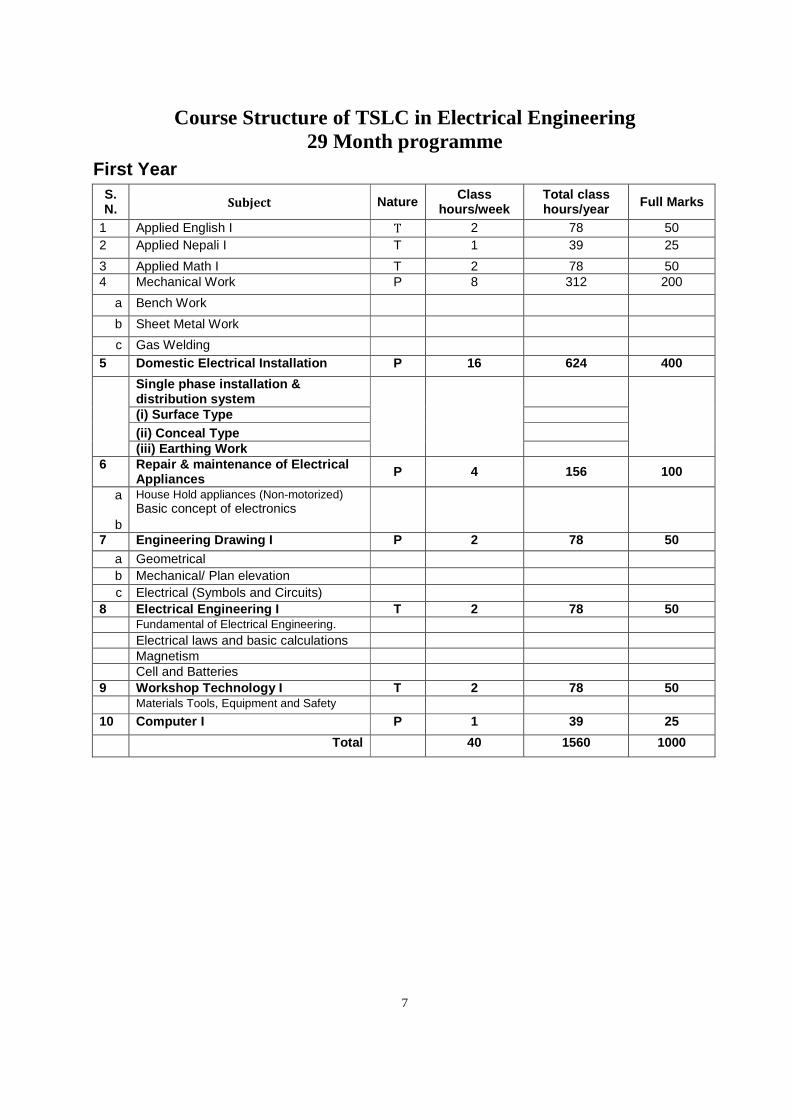
Course Structure of TSLC in Electrical Engineering 29 Month programme
First Year
S. N. Subject Nature Class
hours/week Total class hours/year Full Marks
1 Applied English I T 2 78 50 2 Applied Nepali I T 1 39 25
3 Applied Math I T 2 78 50 4 Mechanical Work P 8 312 200
a Bench Work
b Sheet Metal Work
c Gas Welding 5 Domestic Electrical Installation P 16 624 400
Single phase installation & distribution system
(i) Surface Type (ii) Conceal Type
(iii) Earthing Work 6 Repair & maintenance of Electrical
Appliances P 4 156 100
a
b
House Hold appliances (Non-motorized) Basic concept of electronics
7 Engineering Drawing I P 2 78 50 a Geometrical b Mechanical/ Plan elevation c Electrical (Symbols and Circuits)
8 Electrical Engineering I T 2 78 50 Fundamental of Electrical Engineering. Electrical laws and basic calculations
Magnetism Cell and Batteries 9 Workshop Technology I T 2 78 50 Materials Tools, Equipment and Safety 10 Computer I P 1 39 25
Total 40 1560 1000
8
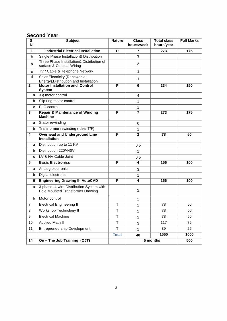
Second Year S. N.
Subject Nature Class hours/week
Total class hours/year
Full Marks
1 Industrial Electrical Installation P 7 273 175 a Single Phase Installation& Distribution 3
b Three Phase Installation& Distribution of surface & Conceal Wiring
2
c TV / Cable & Telephone Network 1
d Solar Electricity (Renewable Energy),Distribution and Installation
1
2 Motor Installation and Control System
P 6 234 150
a 3 φ motor control 4
b Slip ring motor control 1
c PLC control 1
3 Repair & Maintenance of Winding Machine
P 7 273 175
a Stator rewinding 6
b Transformer rewinding (Ideal T/F) 1
4 Overhead and Underground Line Installation
P 2 78 50
a Distribution up to 11 KV 0.5
b Distribution 220/440V 1
c LV & HV Cable Joint 0.5
5 Basic Electronics P 4 156 100
a Analog electronic 3
b Digital electronic 1
6 Engineering Drawing II - AutoCAD P 4 156 100
a 3-phase, 4-wire Distribution System with Pole Mounted Transformer Drawing
2
b Motor control 2
7 Electrical Engineering II T 2 78 50
8 Workshop Technology II T 2 78 50
9 Electrical Machine T 2 78 50
10 Applied Math II T 3 117 75
11 Entrepreneurship Development T 1 39 25
Total 40 1560 1000
14 On – The Job Training (OJT) 5 months 500
9
First year
Subjects 1. Applied English 2. Applied Nepali 3. Applied Math I 4. Mechanical Work 5. Domestic Electrical Installation 6. Repair & maintenance of Electrical Appliances 7. Engineering Drawing I 8. Electrical Engineering I 9. Workshop Technology I 10.Computer I
10
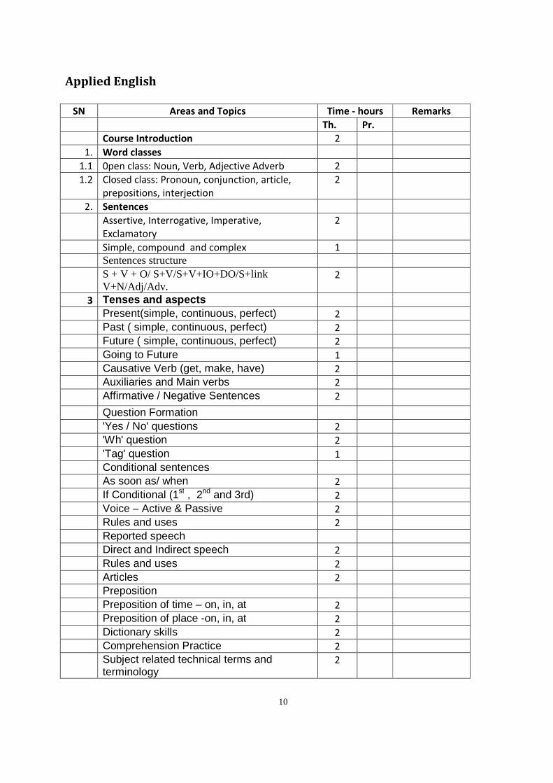
Applied English
SN Areas and Topics Time - hours Remarks
Th. Pr.
Course Introduction 2
1. Word classes
1.1 0pen class: Noun, Verb, Adjective Adverb 2
1.2 Closed class: Pronoun, conjunction, article,
prepositions, interjection
2
2. Sentences
Assertive, Interrogative, Imperative,
Exclamatory
2
Simple, compound and complex 1
Sentences structure
S + V + O/ S+V/S+V+IO+DO/S+link V+N/Adj/Adv.
2
3 Tenses and aspects
Present(simple, continuous, perfect) 2
Past ( simple, continuous, perfect) 2
Future ( simple, continuous, perfect) 2
Going to Future 1
Causative Verb (get, make, have) 2
Auxiliaries and Main verbs 2
Affirmative / Negative Sentences 2
Question Formation
'Yes / No' questions 2
'Wh' question 2
'Tag' question 1
Conditional sentences
As soon as/ when 2
If Conditional (1st , 2nd and 3rd) 2
Voice – Active & Passive 2
Rules and uses 2
Reported speech
Direct and Indirect speech 2
Rules and uses 2
Articles 2
Preposition
Preposition of time – on, in, at 2
Preposition of place -on, in, at 2
Dictionary skills 2
Comprehension Practice 2
Subject related technical terms and terminology
2
11
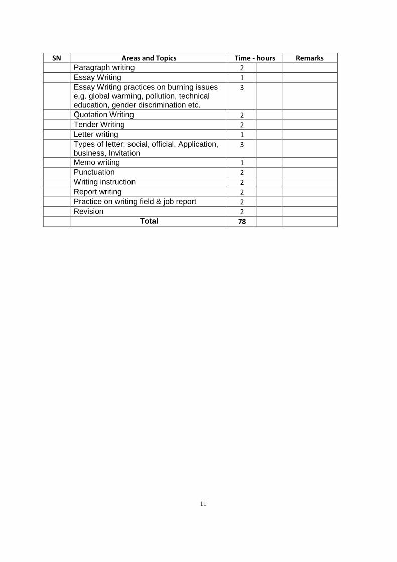
SN Areas and Topics Time - hours Remarks
Paragraph writing 2
Essay Writing 1
Essay Writing practices on burning issues e.g. global warming, pollution, technical education, gender discrimination etc.
3
Quotation Writing 2
Tender Writing 2
Letter writing 1
Types of letter: social, official, Application, business, Invitation
3
Memo writing 1
Punctuation 2
Writing instruction 2
Report writing 2
Practice on writing field & job report 2
Revision 2
Total 78
12
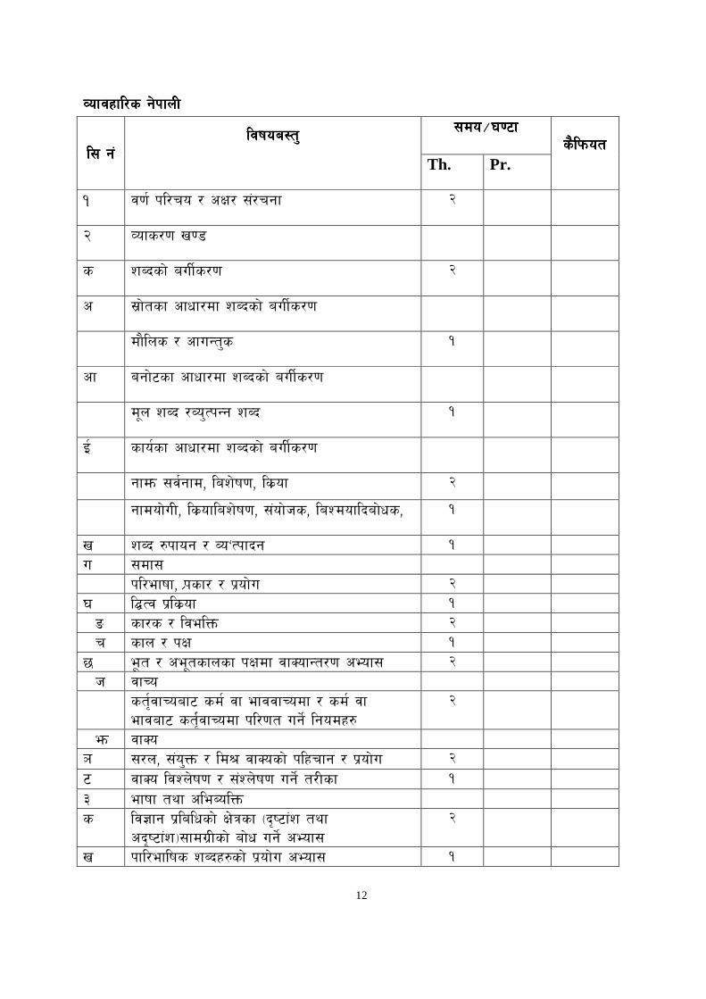
Jofjxfl/sJofjxfl/sJofjxfl/sJofjxfl/s g]kfnLg]kfnLg]kfnLg]kfnL
l; g+l; g+l; g+l; g+ ljifoa:tljifoa:tljifoa:tljifoa:t''''
;do;do;do;do÷÷÷÷306f306f306f306f slkmotslkmotslkmotslkmot
Th. Pr.
! j0f kl/ro / cIf/ ;+/rgf @
@ Jofs/0f v08
s zAbsf] auLs/0f @
c ;|f]tsf cfwf/df zAbsf] auLs/0f
Dfflns / cfuGt's !
cf Afgf]6sf cfwf/df zAbsf] auLs/0f
Df"n zAb /Ao'TkGg zAb !
O sfosf cfwf/df zAbsf] auLs/0f
Gffdm ;jgfd, laz]if0f, ls|of @
Gffdof]uL, ls|oflaz]if0f, ;+of]hs, laZdoflbaf]ws, !
v zAb ?kfog / Ao…Tkfbg ! u ;df;
kl/efiff, K|fsf/ / k|of]u @ 3 l¢Tj k|ls|of ! ª sf/s / ljelQm @ r sfn / kIf ! 5 E"ft / ce"tsfnsf kIfdf jfSofGt/0f cEof; @ h jfRo
st[jfRoaf6 sd jf efjjfRodf / sd jf efjaf6 st[jfRodf kl/0ft ug] lgodx?
@
em jfSo ` ;/n, ;+o'Qm / ld> jfSosf] klxrfg / k|of]u @ ^ jfSo ljZn]if0f / ;+Zn]if0f ug] t/Lsf ! # efiff tyf cleAolQm s lj1fg k|lalwsf] If]qsf -b[i6f+z tyf
cb[i6f+z_;fdu|Lsf] af]w ug] cEof; @
v kfl/eflifs zAbx?sf] k|of]u cEof; !
13
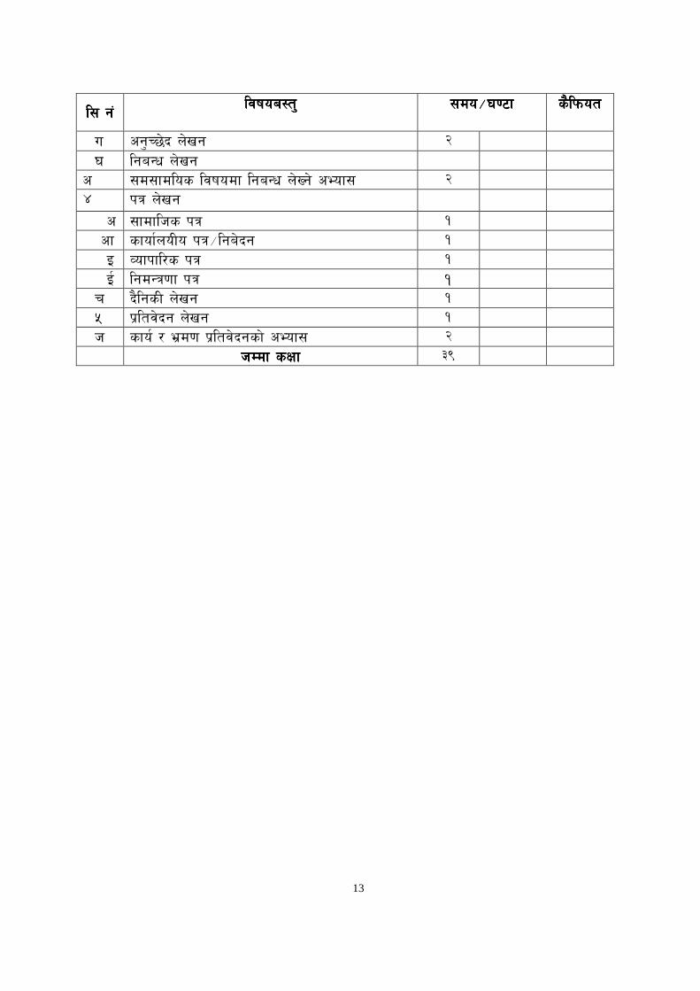
l; g+l; g+l; g+l; g+ ljifoa:tljifoa:tljifoa:tljifoa:t''''
;do;do;do;do÷÷÷÷306f306f306f306f
slkmotslkmotslkmotslkmot
u cg…R5]b n]vg @ 3 lgaGw n]Vfg c ;d;fdlos ljifodf lgaGw n]Vg] cEof; @ $ kq n]vg
c ;fdflhs kq ! cf sfofnoLo kq÷lga]bg ! O Jofkfl/s kq ! O lgdGq0ff kq ! r blgsL n]vg ! % k|ltj]bg n]vg ! h sfo / e|d0f k|ltj]bgsf] cEof; @ hDdf sIffhDdf sIffhDdf sIffhDdf sIff #(
14
Applied Math I
Class/ week: 2 Hours Total class/ year: 78 Hrs
1. Decimal Number
1.1 Addition
2.2 Subtraction
3.3 Multiplication
4.4 Division
2. Common fraction number
1.1 Addition
2.2 Subtraction
3.3 Multiplication
4.4 Division
3. Calculate percentage
4. Calculate area of
1.1 Circle
2.2 Square
3.3 Rectangle
4.4 Triangle
5.5 Ring
6.6 Trapezoid
7.7 Regular pentagon
8.8 Regular hexagon
9.9 Regular octagon
5. Calculate volume of
1.1 Circular shape
2.2 Square shape
3.3 Triangular shape
4.4 Cylinder
6. Convert Centigrade into Fahrenheit and vice versa
7. Convert FPS into MKS (SI) and vice versa
8. Calculate cost per unit using UNITORY METHOD
9. Calculate the mass and density
15
10. Calculate basic statistics
11. Interpret and present simple graphics, charts and maps of
12. Calculate basic algebra, trigonometric and calculus
13. Apply simple linear equation.
14. Identify and interpret scalar and vector quantity.
15. Apply trigonometric Function and its inverse Function.
16. Apply limit of the given function.
17. Apply basic derivative
18. Calculate the resistance
1.1 Resistance law
2.2 Ohm's law
3.3 Resistance in series
4.4 Resistance in parallel
5.5 Kirchhoff’s law
19. Calculate the electromagnetic induction
1.1 Self induction
2.2 Mutual induction.
3.3 Coefficient of coupling
4.4 Induced e.m.f.
5.5 Inductance in series
6.6 Inductance in parallel
20. Calculate the capacitance
1.1 Coulomb's law
2.2 Capacitance, charge and potential different
3.3 Capacitor in series
4.4 Capacitor in Parallel
5.5 Energy store in capacitor
Mechanical Work
Task:
1. Perform surface filling. 88 hrs
2. Perform marking and measuring. 30 hrs
16
3. Perform punching 14 hrs
4. Perform the sawing 30 hrs
5. Perform angle and step filling. 40 hrs
6. Perform the drilling. 20 hrs
7. Perform the cutting (sheet metal) 30 hrs
8. Perform the riveting 20 hrs
9. Perform joint (gas welding) 40 hrs
17
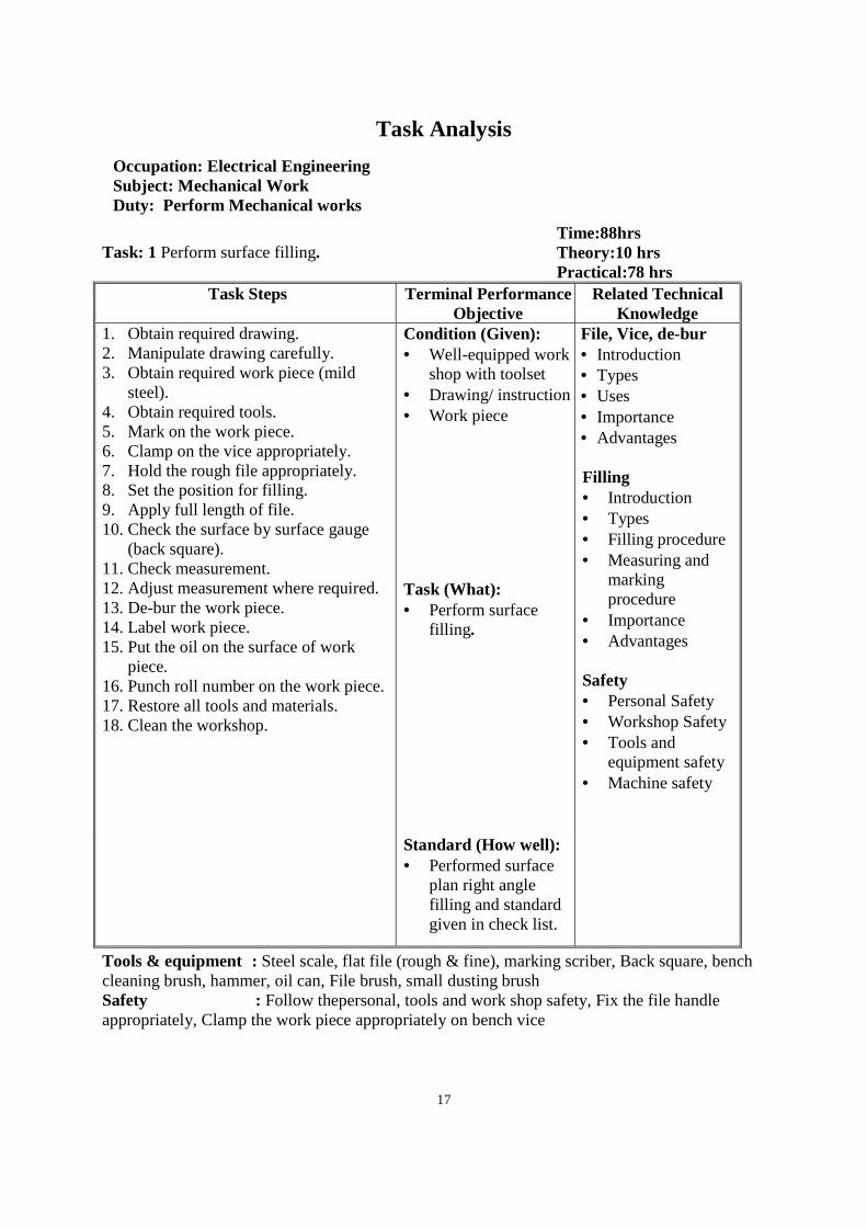
Task Analysis
Occupation: Electrical Engineering Subject: Mechanical Work Duty: Perform Mechanical works
Task: 1 Perform surface filling.
Time:88hrs Theory:10 hrs Practical:78 hrs
Task Steps Terminal Performance Objective
Related Technical Knowledge
1. Obtain required drawing. 2. Manipulate drawing carefully. 3. Obtain required work piece (mild
steel). 4. Obtain required tools. 5. Mark on the work piece. 6. Clamp on the vice appropriately. 7. Hold the rough file appropriately. 8. Set the position for filling. 9. Apply full length of file. 10. Check the surface by surface gauge
(back square). 11. Check measurement. 12. Adjust measurement where required. 13. De-bur the work piece. 14. Label work piece. 15. Put the oil on the surface of work
piece. 16. Punch roll number on the work piece. 17. Restore all tools and materials. 18. Clean the workshop.
Condition (Given): • Well-equipped work
shop with toolset • Drawing/ instruction • Work piece
File, Vice, de-bur • Introduction • Types • Uses • Importance • Advantages Filling • Introduction • Types • Filling procedure • Measuring and
marking procedure
• Importance • Advantages Safety • Personal Safety • Workshop Safety • Tools and
equipment safety • Machine safety
Task (What): • Perform surface
filling .
Standard (How well): • Performed surface
plan right angle filling and standard given in check list.
Tools & equipment : Steel scale, flat file (rough & fine), marking scriber, Back square, bench cleaning brush, hammer, oil can, File brush, small dusting brush Safety : Follow thepersonal, tools and work shop safety, Fix the file handle appropriately, Clamp the work piece appropriately on bench vice
18
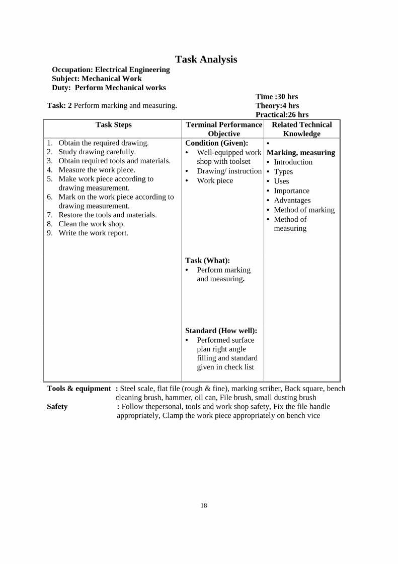
Task Analysis Occupation: Electrical Engineering Subject: Mechanical Work Duty: Perform Mechanical works
Task: 2 Perform marking and measuring.
Time :30 hrs Theory:4 hrs Practical:26 hrs
Task Steps Terminal Performance Objective
Related Technical Knowledge
1. Obtain the required drawing. 2. Study drawing carefully. 3. Obtain required tools and materials. 4. Measure the work piece. 5. Make work piece according to
drawing measurement. 6. Mark on the work piece according to
drawing measurement. 7. Restore the tools and materials. 8. Clean the work shop. 9. Write the work report.
Condition (Given): • Well-equipped work
shop with toolset • Drawing/ instruction • Work piece
• Marking, measuring • Introduction • Types • Uses • Importance • Advantages • Method of marking • Method of
measuring Task (What):
• Perform marking and measuring.
Standard (How well): • Performed surface
plan right angle filling and standard given in check list
Tools & equipment : Steel scale, flat file (rough & fine), marking scriber, Back square, bench cleaning brush, hammer, oil can, File brush, small dusting brush
Safety : Follow thepersonal, tools and work shop safety, Fix the file handle appropriately, Clamp the work piece appropriately on bench vice
19
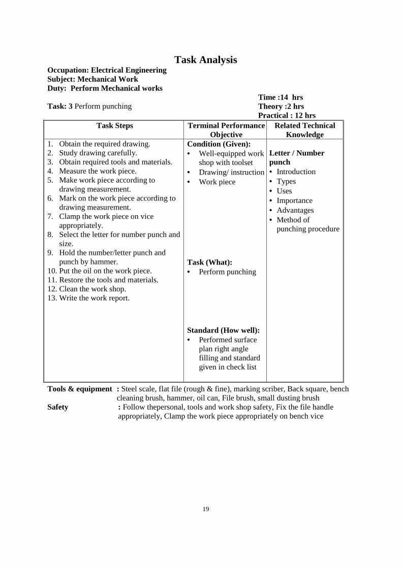
Task Analysis Occupation: Electrical Engineering Subject: Mechanical Work Duty: Perform Mechanical works
Task: 3 Perform punching
Time :14 hrs Theory :2 hrs Practical : 12 hrs
Task Steps Terminal Performance Objective
Related Technical Knowledge
1. Obtain the required drawing. 2. Study drawing carefully. 3. Obtain required tools and materials. 4. Measure the work piece. 5. Make work piece according to
drawing measurement. 6. Mark on the work piece according to
drawing measurement. 7. Clamp the work piece on vice
appropriately. 8. Select the letter for number punch and
size. 9. Hold the number/letter punch and
punch by hammer. 10. Put the oil on the work piece. 11. Restore the tools and materials. 12. Clean the work shop. 13. Write the work report.
Condition (Given): • Well-equipped work
shop with toolset • Drawing/ instruction • Work piece
Letter / Number punch • Introduction • Types • Uses • Importance • Advantages • Method of
punching procedure
Task (What): • Perform punching
Standard (How well): • Performed surface
plan right angle filling and standard given in check list
Tools & equipment : Steel scale, flat file (rough & fine), marking scriber, Back square, bench cleaning brush, hammer, oil can, File brush, small dusting brush
Safety : Follow thepersonal, tools and work shop safety, Fix the file handle appropriately, Clamp the work piece appropriately on bench vice
20
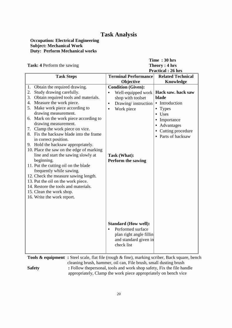
Task Analysis Occupation: Electrical Engineering Subject: Mechanical Work Duty: Perform Mechanical works
Task: 4 Perform the sawing
Time : 30 hrs Theory : 4 hrs Practical : 26 hrs
Task Steps Terminal Performance Objective
Related Technical Knowledge
1. Obtain the required drawing. 2. Study drawing carefully. 3. Obtain required tools and materials. 4. Measure the work piece. 5. Make work piece according to
drawing measurement. 6. Mark on the work piece according to
drawing measurement. 7. Clamp the work piece on vice. 8. Fix the hacksaw blade into the frame
in correct position. 9. Hold the hacksaw appropriately. 10. Place the saw on the edge of marking
line and start the sawing slowly at beginning.
11. Put the cutting oil on the blade frequently while sawing.
12. Check the measure sawing length. 13. Put the oil on the work piece. 14. Restore the tools and materials. 15. Clean the work shop. 16. Write the work report.
Condition (Given): • Well-equipped work
shop with toolset • Drawing/ instruction • Work piece
Hack saw. hack saw blade • Introduction • Types • Uses • Importance • Advantages • Cutting procedure • Parts of hacksaw Task (What):
Perform the sawing
Standard (How well): • Performed surface
plan right angle filling and standard given in check list
Tools & equipment : Steel scale, flat file (rough & fine), marking scriber, Back square, bench cleaning brush, hammer, oil can, File brush, small dusting brush
Safety : Follow thepersonal, tools and work shop safety, Fix the file handle appropriately, Clamp the work piece appropriately on bench vice
21
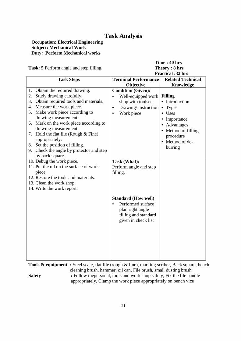
Task Analysis Occupation: Electrical Engineering Subject: Mechanical Work Duty: Perform Mechanical works
Task: 5 Perform angle and step filling.
Time : 40 hrs Theory : 8 hrs Practical :32 hrs
Task Steps Terminal Performance Objective
Related Technical Knowledge
1. Obtain the required drawing. 2. Study drawing carefully. 3. Obtain required tools and materials. 4. Measure the work piece. 5. Make work piece according to
drawing measurement. 6. Mark on the work piece according to
drawing measurement. 7. Hold the flat file (Rough & Fine)
appropriately. 8. Set the position of filling. 9. Check the angle by protector and step
by back square. 10. Debug the work piece. 11. Put the oil on the surface of work
piece. 12. Restore the tools and materials. 13. Clean the work shop. 14. Write the work report.
Condition (Given): • Well-equipped work
shop with toolset • Drawing/ instruction • Work piece
Filling • Introduction • Types • Uses • Importance • Advantages • Method of filling
procedure • Method of de-
burring Task (What):
Perform angle and step filling.
Standard (How well) • Performed surface
plan right angle filling and standard given in check list
Tools & equipment : Steel scale, flat file (rough & fine), marking scriber, Back square, bench cleaning brush, hammer, oil can, File brush, small dusting brush
Safety : Follow thepersonal, tools and work shop safety, Fix the file handle appropriately, Clamp the work piece appropriately on bench vice
22
Task Analysis Occupation: Electrical Engineering Subject: Mechanical Work Duty: Perform Mechanical works
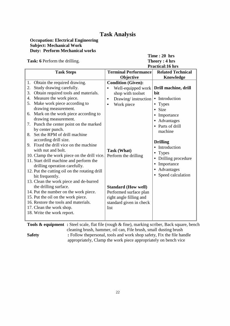
Task: 6 Perform the drilling.
Time : 20 hrs Theory : 4 hrs Practical:16 hrs
Task Steps Terminal Performance Objective
Related Technical Knowledge
1. Obtain the required drawing. 2. Study drawing carefully. 3. Obtain required tools and materials. 4. Measure the work piece. 5. Make work piece according to
drawing measurement. 6. Mark on the work piece according to
drawing measurement. 7. Punch the center point on the marked
by center punch. 8. Set the RPM of drill machine
according drill size. 9. Fixed the drill vice on the machine
with nut and bolt. 10. Clamp the work piece on the drill vice. 11. Start drill machine and perform the
drilling operation carefully. 12. Put the cutting oil on the rotating drill
bit frequently. 13. Clean the work piece and de-burred
the drilling surface. 14. Put the number on the work piece. 15. Put the oil on the work piece. 16. Restore the tools and materials. 17. Clean the work shop. 18. Write the work report.
Condition (Given): • Well-equipped work
shop with toolset • Drawing/ instruction • Work piece
Drill machine, drill bit • Introduction • Types • Size • Importance • Advantages • Parts of drill
machine Drilling • Introduction • Types • Drilling procedure • Importance • Advantages • Speed calculation
Task (What) Perform the drilling Standard (How well) Performed surface plan right angle filling and standard given in check list
Tools & equipment : Steel scale, flat file (rough & fine), marking scriber, Back square, bench cleaning brush, hammer, oil can, File brush, small dusting brush
Safety : Follow thepersonal, tools and work shop safety, Fix the file handle appropriately, Clamp the work piece appropriately on bench vice
23
Task Analysis Occupation: Electrical Engineering Subject: Mechanical Work Duty: Perform Mechanical works
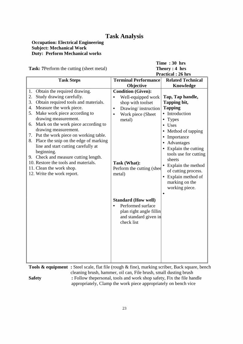
Task: 7Perform the cutting (sheet metal)
Time : 30 hrs Theory : 4 hrs Practical : 26 hrs
Task Steps Terminal Performance Objective
Related Technical Knowledge
1. Obtain the required drawing. 2. Study drawing carefully. 3. Obtain required tools and materials. 4. Measure the work piece. 5. Make work piece according to
drawing measurement. 6. Mark on the work piece according to
drawing measurement. 7. Put the work piece on working table. 8. Place the snip on the edge of marking
line and start cutting carefully at beginning.
9. Check and measure cutting length. 10. Restore the tools and materials. 11. Clean the work shop. 12. Write the work report.
Condition (Given): • Well-equipped work
shop with toolset • Drawing/ instruction • Work piece (Sheet
metal)
Tap, Tap handle, Tapping bit, Tapping • Introduction • Types • Uses • Method of tapping • Importance • Advantages • Explain the cutting
tools use for cutting sheets
• Explain the method of cutting process.
• Explain method of marking on the working piece.
•
Task (What): Perform the cutting (sheet metal)
Standard (How well) • Performed surface
plan right angle filling and standard given in check list
Tools & equipment : Steel scale, flat file (rough & fine), marking scriber, Back square, bench cleaning brush, hammer, oil can, File brush, small dusting brush
Safety : Follow thepersonal, tools and work shop safety, Fix the file handle appropriately, Clamp the work piece appropriately on bench vice
24
Task Analysis Occupation: Electrical Engineering Subject: Mechanical Work Duty: Perform Mechanical works
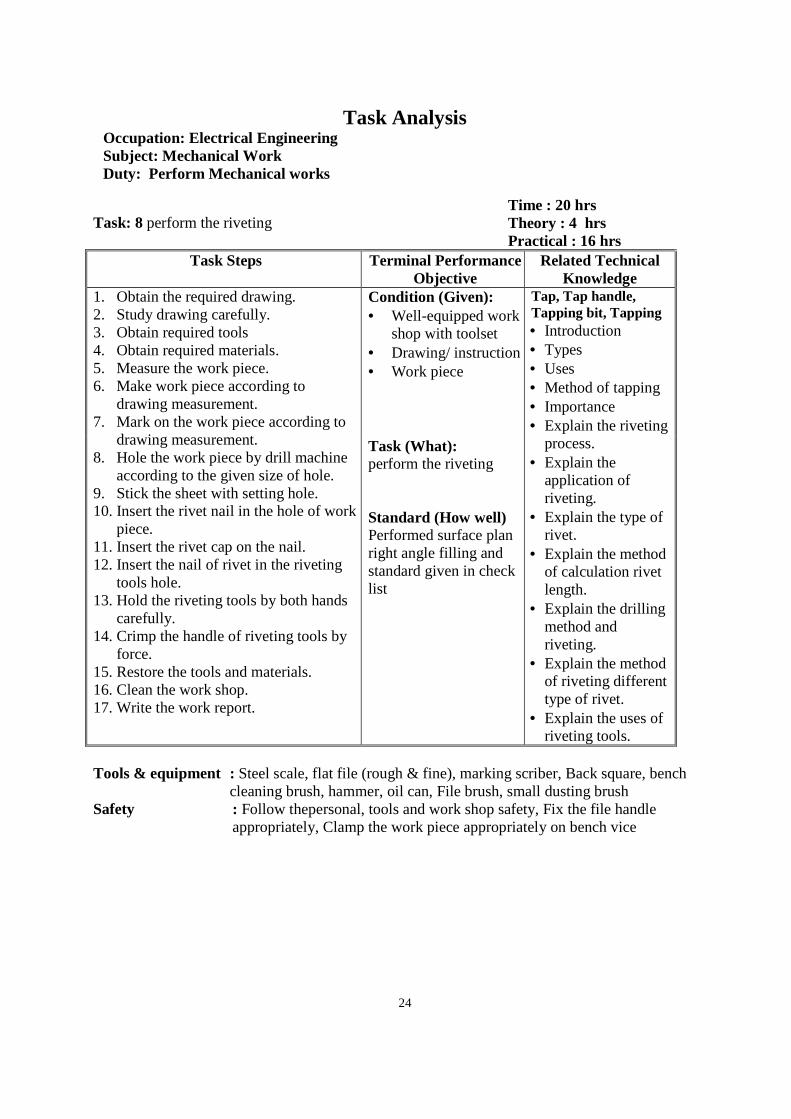
Task: 8 perform the riveting
Time : 20 hrs Theory : 4 hrs Practical : 16 hrs
Task Steps Terminal Performance Objective
Related Technical Knowledge
1. Obtain the required drawing. 2. Study drawing carefully. 3. Obtain required tools 4. Obtain required materials. 5. Measure the work piece. 6. Make work piece according to
drawing measurement. 7. Mark on the work piece according to
drawing measurement. 8. Hole the work piece by drill machine
according to the given size of hole. 9. Stick the sheet with setting hole. 10. Insert the rivet nail in the hole of work
piece. 11. Insert the rivet cap on the nail. 12. Insert the nail of rivet in the riveting
tools hole. 13. Hold the riveting tools by both hands
carefully. 14. Crimp the handle of riveting tools by
force. 15. Restore the tools and materials. 16. Clean the work shop. 17. Write the work report.
Condition (Given): • Well-equipped work
shop with toolset • Drawing/ instruction • Work piece
Tap, Tap handle, Tapping bit, Tapping • Introduction • Types • Uses • Method of tapping • Importance • Explain the riveting
process. • Explain the
application of riveting.
• Explain the type of rivet.
• Explain the method of calculation rivet length.
• Explain the drilling method and riveting.
• Explain the method of riveting different type of rivet.
• Explain the uses of riveting tools.
Task (What): perform the riveting Standard (How well) Performed surface plan right angle filling and standard given in check list
Tools & equipment : Steel scale, flat file (rough & fine), marking scriber, Back square, bench
cleaning brush, hammer, oil can, File brush, small dusting brush Safety : Follow thepersonal, tools and work shop safety, Fix the file handle
appropriately, Clamp the work piece appropriately on bench vice
25
Task Analysis Occupation: Electrical Engineering Subject: Mechanical Work Duty :Perform Mechanical works
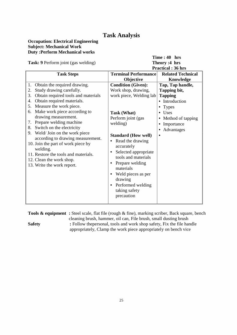
Task: 9 Perform joint (gas welding)
Time : 40 hrs Theory :4 hrs Practical : 36 hrs
Task Steps Terminal Performance Objective
Related Technical Knowledge
1. Obtain the required drawing. 2. Study drawing carefully. 3. Obtain required tools and materials 4. Obtain required materials. 5. Measure the work piece. 6. Make work piece according to
drawing measurement. 7. Prepare welding machine 8. Switch on the electricity 9. Weld/ Join on the work piece
according to drawing measurement. 10. Join the part of work piece by
welding. 11. Restore the tools and materials. 12. Clean the work shop. 13. Write the work report.
Condition (Given): Work shop, drawing, work piece, Welding lab
Tap, Tap handle, Tapping bit, Tapping • Introduction • Types • Uses • Method of tapping • Importance • Advantages •
Task (What) Perform joint (gas welding)
Standard (How well) • Read the drawing
accurately • Selected appropriate
tools and materials • Prepare welding
materials • Weld pieces as per
drawing • Performed welding
taking safety precaution
Tools & equipment : Steel scale, flat file (rough & fine), marking scriber, Back square, bench
cleaning brush, hammer, oil can, File brush, small dusting brush Safety : Follow thepersonal, tools and work shop safety, Fix the file handle
appropriately, Clamp the work piece appropriately on bench vice
26
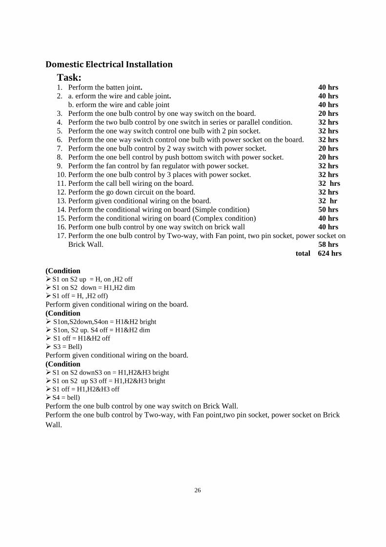
Domestic Electrical Installation
Task: 1. Perform the batten joint. 40 hrs 2. a. erform the wire and cable joint. 40 hrs
b. erform the wire and cable joint 40 hrs 3. Perform the one bulb control by one way switch on the board. 20 hrs 4. Perform the two bulb control by one switch in series or parallel condition. 32 hrs 5. Perform the one way switch control one bulb with 2 pin socket. 32 hrs 6. Perform the one way switch control one bulb with power socket on the board. 32 hrs 7. Perform the one bulb control by 2 way switch with power socket. 20 hrs 8. Perform the one bell control by push bottom switch with power socket. 20 hrs 9. Perform the fan control by fan regulator with power socket. 32 hrs 10. Perform the one bulb control by 3 places with power socket. 32 hrs 11. Perform the call bell wiring on the board. 32 hrs 12. Perform the go down circuit on the board. 32 hrs 13. Perform given conditional wiring on the board. 32 hr 14. Perform the conditional wiring on board (Simple condition) 50 hrs 15. Perform the conditional wiring on board (Complex condition) 40 hrs 16. Perform one bulb control by one way switch on brick wall 40 hrs 17. Perform the one bulb control by Two-way, with Fan point, two pin socket, power socket on
Brick Wall. 58 hrs total 624 hrs
(Condition S1 on S2 up = H, on ,H2 off S1 on S2 down = H1,H2 dim S1 off = H, ,H2 off) Perform given conditional wiring on the board. (Condition S1on,S2down,S4on = H1&H2 bright S1on, S2 up. S4 off = H1&H2 dim S1 off = H1&H2 off S3 = Bell) Perform given conditional wiring on the board. (Condition S1 on S2 downS3 on = H1,H2&H3 bright S1 on S2 up S3 off = H1,H2&H3 bright S1 off = H1,H2&H3 off S4 = bell) Perform the one bulb control by one way switch on Brick Wall. Perform the one bulb control by Two-way, with Fan point,two pin socket, power socket on Brick Wall.
27
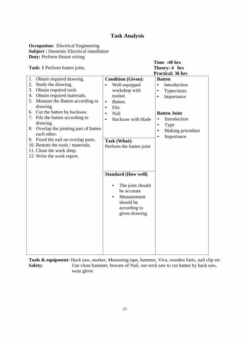
Task Analysis Occupation: Electrical Engineering Subject : Domestic Electrical installation Duty: Perform House wiring Task: 1 Perform batten joint.
Time :40 hrs Theory: 4 hrs Practical: 36 hrs
1. Obtain required drawing. 2. Study the drawing. 3. Obtain required tools 4. Obtain required materials. 5. Measure the Batten according to
drawing. 6. Cut the batten by hacksaw. 7. File the batten according to
drawing. 8. Overlap the jointing part of batten
each other. 9. Fixed the nail on overlap parts. 10. Restore the tools / materials. 11. Clean the work shop. 12. Write the work report.
Condition (Given): • Well-equipped
workshop with toolset
• Batten. • File • Nail • Hacksaw with blade
Batten • Introduction • Types/sizes • Importance Batten Joint • Introduction • Type • Making procedure • Importance
Task (What): Perform the batten joint Standard (How well)
• The joint should be accurate
• Measurement should be according to given drawing
Tools & equipment: Hack saw, marker, Measuring tape, hammer, Vice, wooden listic, nail clip etc Safety: Use clean hammer, beware of Nail, use sock saw to cut batten by hack saw,
wear glove
28
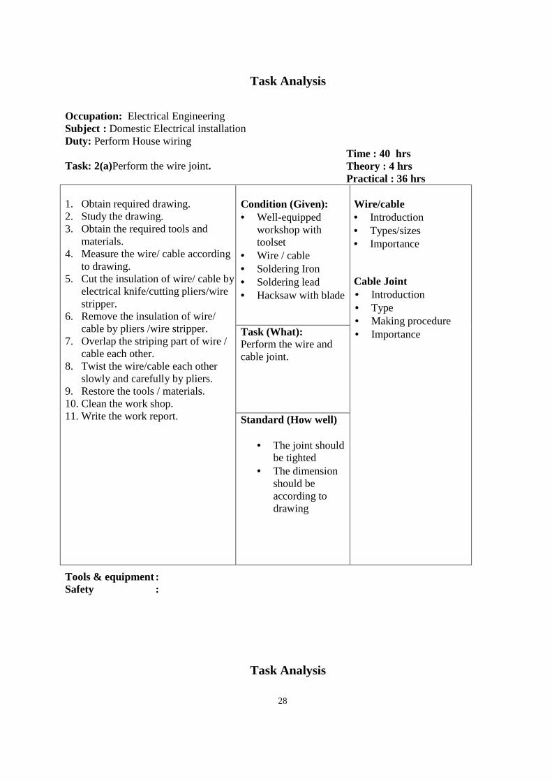
Task Analysis Occupation: Electrical Engineering Subject : Domestic Electrical installation Duty: Perform House wiring Task: 2(a)Perform the wire joint.
Time : 40 hrs Theory : 4 hrs Practical : 36 hrs
1. Obtain required drawing. 2. Study the drawing. 3. Obtain the required tools and
materials. 4. Measure the wire/ cable according
to drawing. 5. Cut the insulation of wire/ cable by
electrical knife/cutting pliers/wire stripper.
6. Remove the insulation of wire/ cable by pliers /wire stripper.
7. Overlap the striping part of wire / cable each other.
8. Twist the wire/cable each other slowly and carefully by pliers.
9. Restore the tools / materials. 10. Clean the work shop. 11. Write the work report.
Condition (Given): • Well-equipped
workshop with toolset
• Wire / cable • Soldering Iron • Soldering lead • Hacksaw with blade
Wire/cable • Introduction • Types/sizes • Importance
Cable Joint • Introduction • Type • Making procedure • Importance
Task (What): Perform the wire and cable joint. Standard (How well)
• The joint should be tighted
• The dimension should be according to drawing
Tools & equipment : Safety :
Task Analysis
29
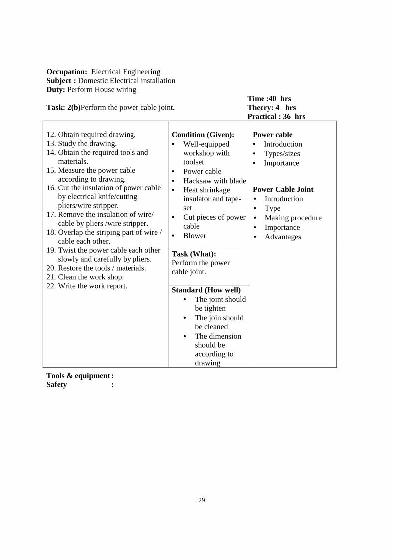
Occupation: Electrical Engineering Subject : Domestic Electrical installation Duty: Perform House wiring Task: 2(b)Perform the power cable joint.
Time :40 hrs Theory: 4 hrs Practical : 36 hrs
12. Obtain required drawing. 13. Study the drawing. 14. Obtain the required tools and
materials. 15. Measure the power cable
according to drawing. 16. Cut the insulation of power cable
by electrical knife/cutting pliers/wire stripper.
17. Remove the insulation of wire/ cable by pliers /wire stripper.
18. Overlap the striping part of wire / cable each other.
19. Twist the power cable each other slowly and carefully by pliers.
20. Restore the tools / materials. 21. Clean the work shop. 22. Write the work report.
Condition (Given): • Well-equipped
workshop with toolset
• Power cable • Hacksaw with blade • Heat shrinkage
insulator and tape-set
• Cut pieces of power cable
• Blower
Power cable • Introduction • Types/sizes • Importance
Power Cable Joint • Introduction • Type • Making procedure • Importance • Advantages
Task (What): Perform the power cable joint. Standard (How well)
• The joint should be tighten
• The join should be cleaned
• The dimension should be according to drawing
Tools & equipment : Safety :
30
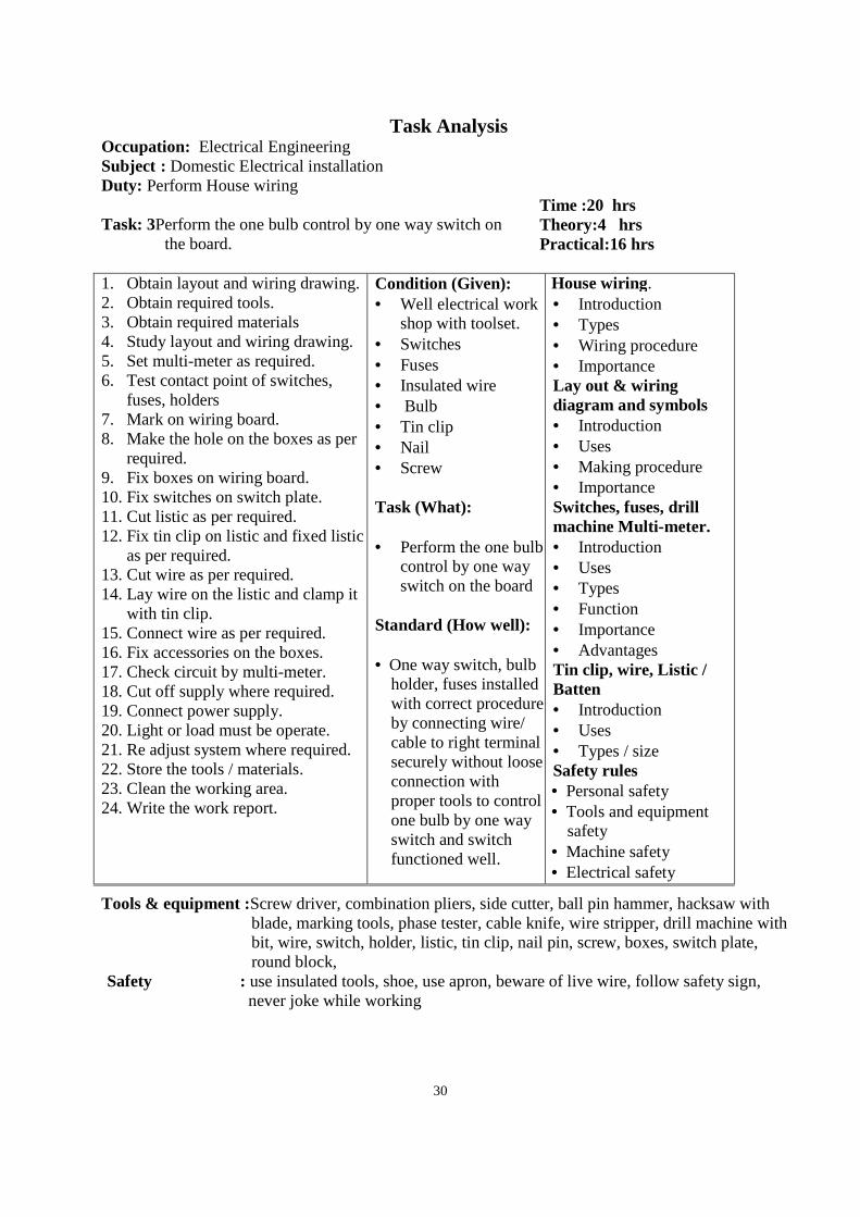
Task Analysis Occupation: Electrical Engineering Subject : Domestic Electrical installation Duty: Perform House wiring Task: 3Perform the one bulb control by one way switch on
the board.
Time :20 hrs Theory:4 hrs Practical:16 hrs
1. Obtain layout and wiring drawing. 2. Obtain required tools. 3. Obtain required materials 4. Study layout and wiring drawing. 5. Set multi-meter as required. 6. Test contact point of switches,
fuses, holders 7. Mark on wiring board. 8. Make the hole on the boxes as per
required. 9. Fix boxes on wiring board. 10. Fix switches on switch plate. 11. Cut listic as per required. 12. Fix tin clip on listic and fixed listic
as per required. 13. Cut wire as per required. 14. Lay wire on the listic and clamp it
with tin clip. 15. Connect wire as per required. 16. Fix accessories on the boxes. 17. Check circuit by multi-meter. 18. Cut off supply where required. 19. Connect power supply. 20. Light or load must be operate. 21. Re adjust system where required. 22. Store the tools / materials. 23. Clean the working area. 24. Write the work report.
Condition (Given): • Well electrical work
shop with toolset. • Switches • Fuses • Insulated wire • Bulb • Tin clip • Nail • Screw Task (What): • Perform the one bulb
control by one way switch on the board
Standard (How well): • One way switch, bulb
holder, fuses installed with correct procedure by connecting wire/ cable to right terminal securely without loose connection with proper tools to control one bulb by one way switch and switch functioned well.
House wiring. • Introduction • Types • Wiring procedure • Importance Lay out & wiring diagram and symbols • Introduction • Uses • Making procedure • Importance Switches, fuses, drill machine Multi-meter. • Introduction • Uses • Types • Function • Importance • Advantages Tin clip, wire, Listic / Batten • Introduction • Uses • Types / size Safety rules • Personal safety • Tools and equipment
safety • Machine safety • Electrical safety
Tools & equipment :Screw driver, combination pliers, side cutter, ball pin hammer, hacksaw with blade, marking tools, phase tester, cable knife, wire stripper, drill machine with bit, wire, switch, holder, listic, tin clip, nail pin, screw, boxes, switch plate, round block,
Safety : use insulated tools, shoe, use apron, beware of live wire, follow safety sign, never joke while working
31
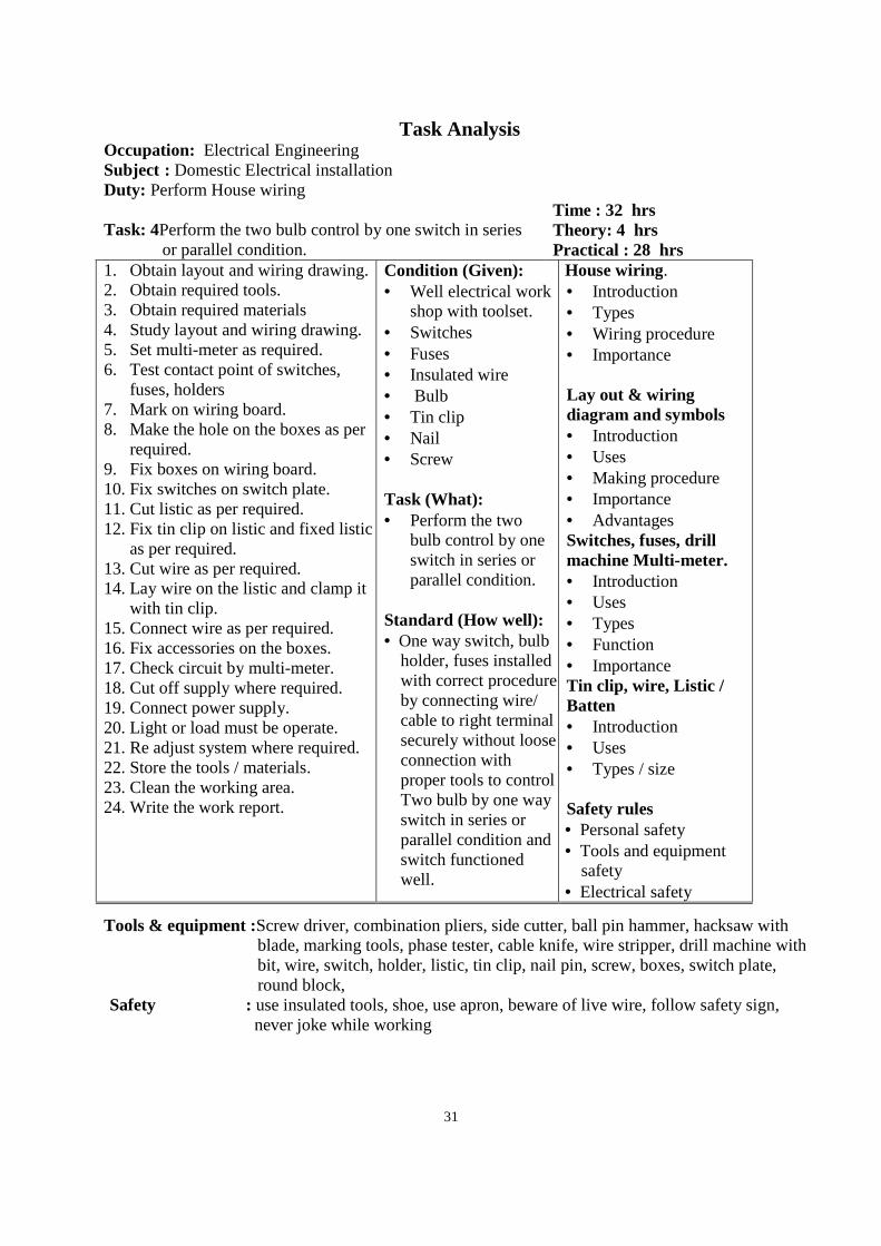
Task Analysis Occupation: Electrical Engineering Subject : Domestic Electrical installation Duty: Perform House wiring Task: 4Perform the two bulb control by one switch in series
or parallel condition.
Time : 32 hrs Theory: 4 hrs Practical : 28 hrs
1. Obtain layout and wiring drawing. 2. Obtain required tools. 3. Obtain required materials 4. Study layout and wiring drawing. 5. Set multi-meter as required. 6. Test contact point of switches,
fuses, holders 7. Mark on wiring board. 8. Make the hole on the boxes as per
required. 9. Fix boxes on wiring board. 10. Fix switches on switch plate. 11. Cut listic as per required. 12. Fix tin clip on listic and fixed listic
as per required. 13. Cut wire as per required. 14. Lay wire on the listic and clamp it
with tin clip. 15. Connect wire as per required. 16. Fix accessories on the boxes. 17. Check circuit by multi-meter. 18. Cut off supply where required. 19. Connect power supply. 20. Light or load must be operate. 21. Re adjust system where required. 22. Store the tools / materials. 23. Clean the working area. 24. Write the work report.
Condition (Given): • Well electrical work
shop with toolset. • Switches • Fuses • Insulated wire • Bulb • Tin clip • Nail • Screw Task (What): • Perform the two
bulb control by one switch in series or parallel condition.
Standard (How well): • One way switch, bulb
holder, fuses installed with correct procedure by connecting wire/ cable to right terminal securely without loose connection with proper tools to control Two bulb by one way switch in series or parallel condition and switch functioned well.
House wiring. • Introduction • Types • Wiring procedure • Importance
Lay out & wiring diagram and symbols • Introduction • Uses • Making procedure • Importance • Advantages Switches, fuses, drill machine Multi-meter. • Introduction • Uses • Types • Function • Importance Tin clip, wire, Listic / Batten • Introduction • Uses • Types / size Safety rules • Personal safety • Tools and equipment
safety • Electrical safety
Tools & equipment :Screw driver, combination pliers, side cutter, ball pin hammer, hacksaw with blade, marking tools, phase tester, cable knife, wire stripper, drill machine with bit, wire, switch, holder, listic, tin clip, nail pin, screw, boxes, switch plate, round block,
Safety : use insulated tools, shoe, use apron, beware of live wire, follow safety sign, never joke while working
32
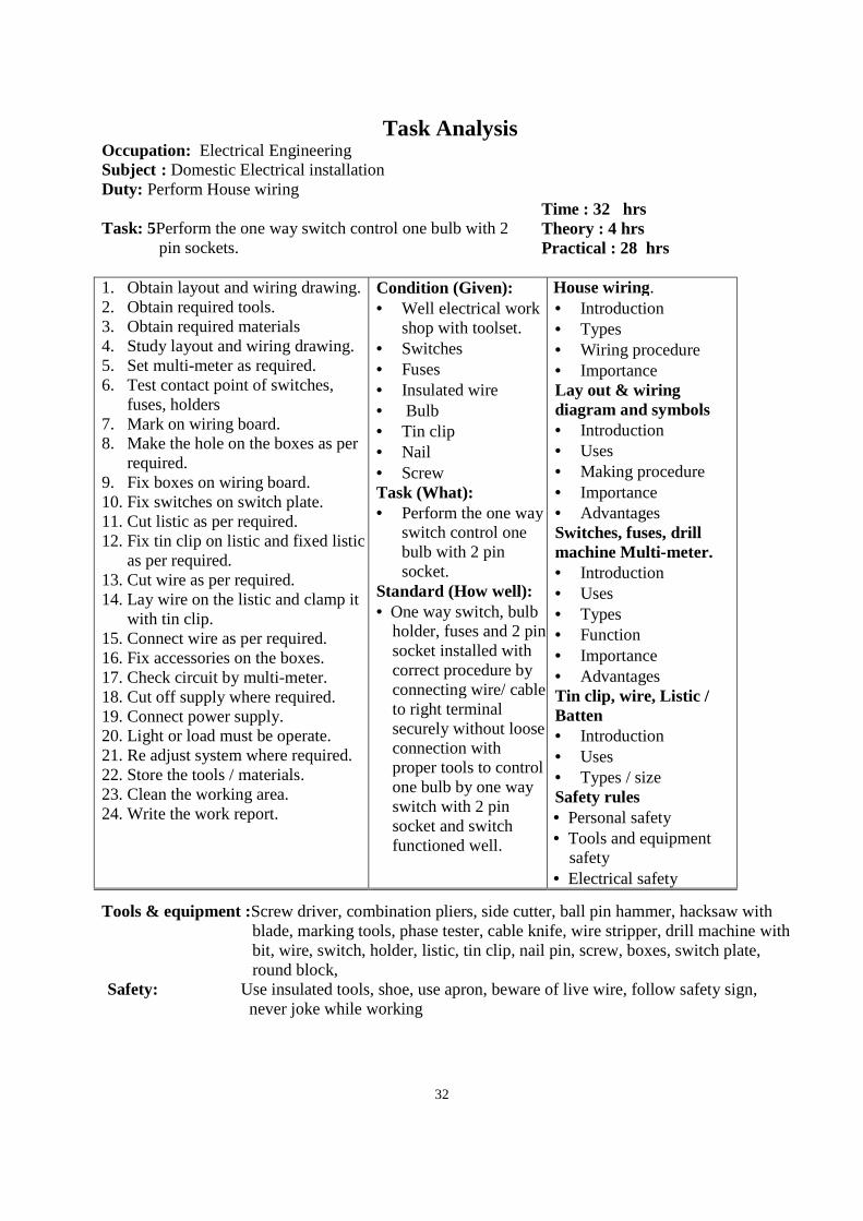
Task Analysis Occupation: Electrical Engineering Subject : Domestic Electrical installation Duty: Perform House wiring Task: 5Perform the one way switch control one bulb with 2
pin sockets.
Time : 32 hrs Theory : 4 hrs Practical : 28 hrs
1. Obtain layout and wiring drawing. 2. Obtain required tools. 3. Obtain required materials 4. Study layout and wiring drawing. 5. Set multi-meter as required. 6. Test contact point of switches,
fuses, holders 7. Mark on wiring board. 8. Make the hole on the boxes as per
required. 9. Fix boxes on wiring board. 10. Fix switches on switch plate. 11. Cut listic as per required. 12. Fix tin clip on listic and fixed listic
as per required. 13. Cut wire as per required. 14. Lay wire on the listic and clamp it
with tin clip. 15. Connect wire as per required. 16. Fix accessories on the boxes. 17. Check circuit by multi-meter. 18. Cut off supply where required. 19. Connect power supply. 20. Light or load must be operate. 21. Re adjust system where required. 22. Store the tools / materials. 23. Clean the working area. 24. Write the work report.
Condition (Given): • Well electrical work
shop with toolset. • Switches • Fuses • Insulated wire • Bulb • Tin clip • Nail • Screw Task (What): • Perform the one way
switch control one bulb with 2 pin socket.
Standard (How well): • One way switch, bulb
holder, fuses and 2 pin socket installed with correct procedure by connecting wire/ cable to right terminal securely without loose connection with proper tools to control one bulb by one way switch with 2 pin socket and switch functioned well.
House wiring. • Introduction • Types • Wiring procedure • Importance Lay out & wiring diagram and symbols • Introduction • Uses • Making procedure • Importance • Advantages Switches, fuses, drill machine Multi-meter. • Introduction • Uses • Types • Function • Importance • Advantages Tin clip, wire, Listic / Batten • Introduction • Uses • Types / size Safety rules • Personal safety • Tools and equipment
safety • Electrical safety
Tools & equipment :Screw driver, combination pliers, side cutter, ball pin hammer, hacksaw with blade, marking tools, phase tester, cable knife, wire stripper, drill machine with bit, wire, switch, holder, listic, tin clip, nail pin, screw, boxes, switch plate, round block,
Safety: Use insulated tools, shoe, use apron, beware of live wire, follow safety sign, never joke while working
33
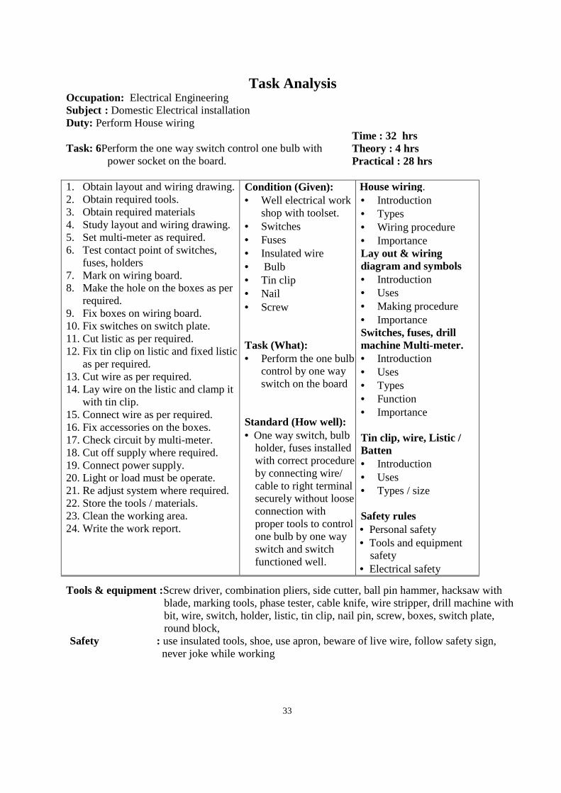
Task Analysis Occupation: Electrical Engineering Subject : Domestic Electrical installation Duty: Perform House wiring Task: 6Perform the one way switch control one bulb with
power socket on the board.
Time : 32 hrs Theory : 4 hrs Practical : 28 hrs
1. Obtain layout and wiring drawing. 2. Obtain required tools. 3. Obtain required materials 4. Study layout and wiring drawing. 5. Set multi-meter as required. 6. Test contact point of switches,
fuses, holders 7. Mark on wiring board. 8. Make the hole on the boxes as per
required. 9. Fix boxes on wiring board. 10. Fix switches on switch plate. 11. Cut listic as per required. 12. Fix tin clip on listic and fixed listic
as per required. 13. Cut wire as per required. 14. Lay wire on the listic and clamp it
with tin clip. 15. Connect wire as per required. 16. Fix accessories on the boxes. 17. Check circuit by multi-meter. 18. Cut off supply where required. 19. Connect power supply. 20. Light or load must be operate. 21. Re adjust system where required. 22. Store the tools / materials. 23. Clean the working area. 24. Write the work report.
Condition (Given): • Well electrical work
shop with toolset. • Switches • Fuses • Insulated wire • Bulb • Tin clip • Nail • Screw Task (What): • Perform the one bulb
control by one way switch on the board
Standard (How well): • One way switch, bulb
holder, fuses installed with correct procedure by connecting wire/ cable to right terminal securely without loose connection with proper tools to control one bulb by one way switch and switch functioned well.
House wiring. • Introduction • Types • Wiring procedure • Importance Lay out & wiring diagram and symbols • Introduction • Uses • Making procedure • Importance Switches, fuses, drill machine Multi-meter. • Introduction • Uses • Types • Function • Importance Tin clip, wire, Listic / Batten • Introduction • Uses • Types / size Safety rules • Personal safety • Tools and equipment
safety • Electrical safety
Tools & equipment :Screw driver, combination pliers, side cutter, ball pin hammer, hacksaw with blade, marking tools, phase tester, cable knife, wire stripper, drill machine with bit, wire, switch, holder, listic, tin clip, nail pin, screw, boxes, switch plate, round block,
Safety : use insulated tools, shoe, use apron, beware of live wire, follow safety sign, never joke while working
34
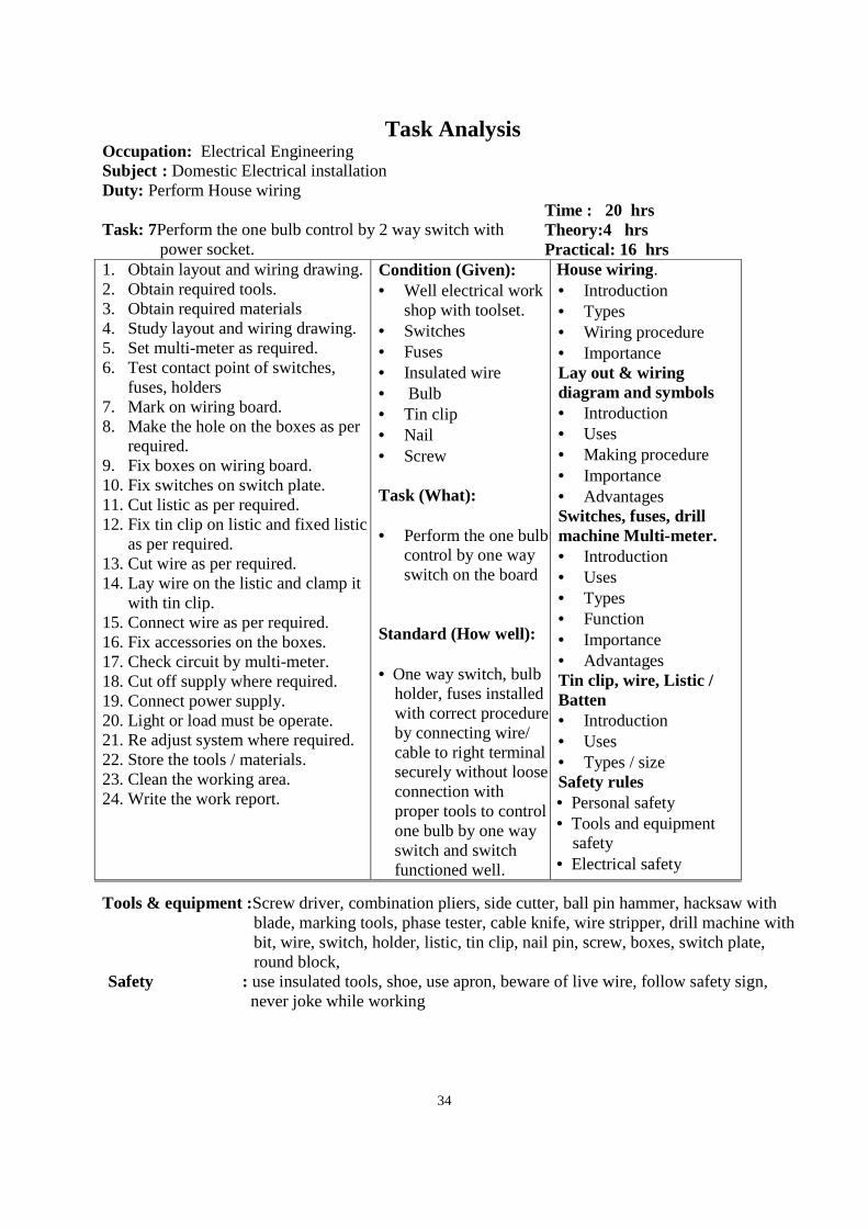
Task Analysis Occupation: Electrical Engineering Subject : Domestic Electrical installation Duty: Perform House wiring Task: 7Perform the one bulb control by 2 way switch with
power socket.
Time : 20 hrs Theory:4 hrs Practical: 16 hrs
1. Obtain layout and wiring drawing. 2. Obtain required tools. 3. Obtain required materials 4. Study layout and wiring drawing. 5. Set multi-meter as required. 6. Test contact point of switches,
fuses, holders 7. Mark on wiring board. 8. Make the hole on the boxes as per
required. 9. Fix boxes on wiring board. 10. Fix switches on switch plate. 11. Cut listic as per required. 12. Fix tin clip on listic and fixed listic
as per required. 13. Cut wire as per required. 14. Lay wire on the listic and clamp it
with tin clip. 15. Connect wire as per required. 16. Fix accessories on the boxes. 17. Check circuit by multi-meter. 18. Cut off supply where required. 19. Connect power supply. 20. Light or load must be operate. 21. Re adjust system where required. 22. Store the tools / materials. 23. Clean the working area. 24. Write the work report.
Condition (Given): • Well electrical work
shop with toolset. • Switches • Fuses • Insulated wire • Bulb • Tin clip • Nail • Screw Task (What): • Perform the one bulb
control by one way switch on the board
Standard (How well): • One way switch, bulb
holder, fuses installed with correct procedure by connecting wire/ cable to right terminal securely without loose connection with proper tools to control one bulb by one way switch and switch functioned well.
House wiring. • Introduction • Types • Wiring procedure • Importance Lay out & wiring diagram and symbols • Introduction • Uses • Making procedure • Importance • Advantages Switches, fuses, drill machine Multi-meter. • Introduction • Uses • Types • Function • Importance • Advantages Tin clip, wire, Listic / Batten • Introduction • Uses • Types / size Safety rules • Personal safety • Tools and equipment
safety • Electrical safety
Tools & equipment :Screw driver, combination pliers, side cutter, ball pin hammer, hacksaw with blade, marking tools, phase tester, cable knife, wire stripper, drill machine with bit, wire, switch, holder, listic, tin clip, nail pin, screw, boxes, switch plate, round block,
Safety : use insulated tools, shoe, use apron, beware of live wire, follow safety sign, never joke while working
35
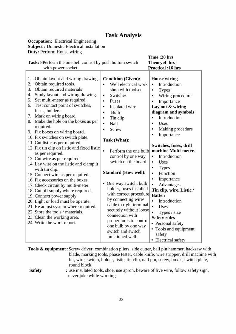
Task Analysis Occupation: Electrical Engineering Subject : Domestic Electrical installation Duty: Perform House wiring Task: 8Perform the one bell control by push bottom switch
with power socket.
Time :20 hrs Theory:4 hrs Practical :16 hrs
1. Obtain layout and wiring drawing. 2. Obtain required tools. 3. Obtain required materials 4. Study layout and wiring drawing. 5. Set multi-meter as required. 6. Test contact point of switches,
fuses, holders 7. Mark on wiring board. 8. Make the hole on the boxes as per
required. 9. Fix boxes on wiring board. 10. Fix switches on switch plate. 11. Cut listic as per required. 12. Fix tin clip on listic and fixed listic
as per required. 13. Cut wire as per required. 14. Lay wire on the listic and clamp it
with tin clip. 15. Connect wire as per required. 16. Fix accessories on the boxes. 17. Check circuit by multi-meter. 18. Cut off supply where required. 19. Connect power supply. 20. Light or load must be operate. 21. Re adjust system where required. 22. Store the tools / materials. 23. Clean the working area. 24. Write the work report.
Condition (Given): • Well electrical work
shop with toolset. • Switches • Fuses • Insulated wire • Bulb • Tin clip • Nail • Screw Task (What): • Perform the one bulb
control by one way switch on the board
Standard (How well): • One way switch, bulb
holder, fuses installed with correct procedure by connecting wire/ cable to right terminal securely without loose connection with proper tools to control one bulb by one way switch and switch functioned well.
House wiring. • Introduction • Types • Wiring procedure • Importance Lay out & wiring diagram and symbols • Introduction • Uses • Making procedure • Importance Switches, fuses, drill machine Multi-meter. • Introduction • Uses • Types • Function • Importance • Advantages Tin clip, wire, Listic / Batten • Introduction • Uses • Types / size Safety rules • Personal safety • Tools and equipment
safety • Electrical safety
Tools & equipment :Screw driver, combination pliers, side cutter, ball pin hammer, hacksaw with blade, marking tools, phase tester, cable knife, wire stripper, drill machine with bit, wire, switch, holder, listic, tin clip, nail pin, screw, boxes, switch plate, round block,
Safety : use insulated tools, shoe, use apron, beware of live wire, follow safety sign, never joke while working
36
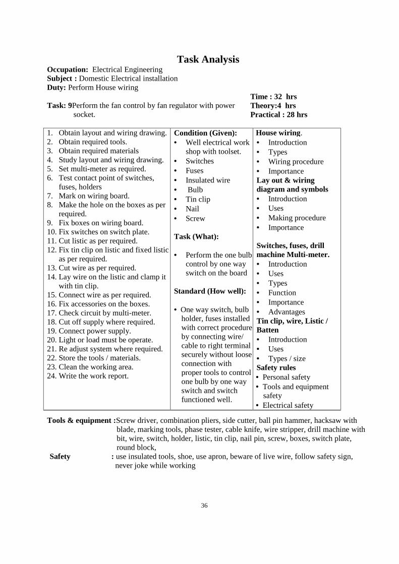
Task Analysis Occupation: Electrical Engineering Subject : Domestic Electrical installation Duty: Perform House wiring Task: 9Perform the fan control by fan regulator with power
socket.
Time : 32 hrs Theory:4 hrs Practical : 28 hrs
1. Obtain layout and wiring drawing. 2. Obtain required tools. 3. Obtain required materials 4. Study layout and wiring drawing. 5. Set multi-meter as required. 6. Test contact point of switches,
fuses, holders 7. Mark on wiring board. 8. Make the hole on the boxes as per
required. 9. Fix boxes on wiring board. 10. Fix switches on switch plate. 11. Cut listic as per required. 12. Fix tin clip on listic and fixed listic
as per required. 13. Cut wire as per required. 14. Lay wire on the listic and clamp it
with tin clip. 15. Connect wire as per required. 16. Fix accessories on the boxes. 17. Check circuit by multi-meter. 18. Cut off supply where required. 19. Connect power supply. 20. Light or load must be operate. 21. Re adjust system where required. 22. Store the tools / materials. 23. Clean the working area. 24. Write the work report.
Condition (Given): • Well electrical work
shop with toolset. • Switches • Fuses • Insulated wire • Bulb • Tin clip • Nail • Screw Task (What): • Perform the one bulb
control by one way switch on the board
Standard (How well): • One way switch, bulb
holder, fuses installed with correct procedure by connecting wire/ cable to right terminal securely without loose connection with proper tools to control one bulb by one way switch and switch functioned well.
House wiring. • Introduction • Types • Wiring procedure • Importance Lay out & wiring diagram and symbols • Introduction • Uses • Making procedure • Importance Switches, fuses, drill machine Multi-meter. • Introduction • Uses • Types • Function • Importance • Advantages Tin clip, wire, Listic / Batten • Introduction • Uses • Types / size Safety rules • Personal safety • Tools and equipment
safety • Electrical safety
Tools & equipment :Screw driver, combination pliers, side cutter, ball pin hammer, hacksaw with blade, marking tools, phase tester, cable knife, wire stripper, drill machine with bit, wire, switch, holder, listic, tin clip, nail pin, screw, boxes, switch plate, round block,
Safety : use insulated tools, shoe, use apron, beware of live wire, follow safety sign, never joke while working
37
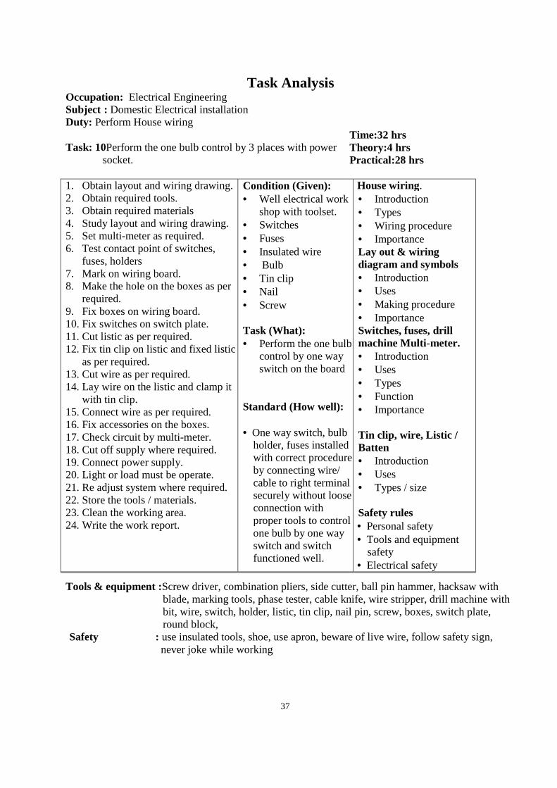
Task Analysis Occupation: Electrical Engineering Subject : Domestic Electrical installation Duty: Perform House wiring Task: 10Perform the one bulb control by 3 places with power
socket.
Time:32 hrs Theory:4 hrs Practical:28 hrs
1. Obtain layout and wiring drawing. 2. Obtain required tools. 3. Obtain required materials 4. Study layout and wiring drawing. 5. Set multi-meter as required. 6. Test contact point of switches,
fuses, holders 7. Mark on wiring board. 8. Make the hole on the boxes as per
required. 9. Fix boxes on wiring board. 10. Fix switches on switch plate. 11. Cut listic as per required. 12. Fix tin clip on listic and fixed listic
as per required. 13. Cut wire as per required. 14. Lay wire on the listic and clamp it
with tin clip. 15. Connect wire as per required. 16. Fix accessories on the boxes. 17. Check circuit by multi-meter. 18. Cut off supply where required. 19. Connect power supply. 20. Light or load must be operate. 21. Re adjust system where required. 22. Store the tools / materials. 23. Clean the working area. 24. Write the work report.
Condition (Given): • Well electrical work
shop with toolset. • Switches • Fuses • Insulated wire • Bulb • Tin clip • Nail • Screw Task (What): • Perform the one bulb
control by one way switch on the board
Standard (How well): • One way switch, bulb
holder, fuses installed with correct procedure by connecting wire/ cable to right terminal securely without loose connection with proper tools to control one bulb by one way switch and switch functioned well.
House wiring. • Introduction • Types • Wiring procedure • Importance Lay out & wiring diagram and symbols • Introduction • Uses • Making procedure • Importance Switches, fuses, drill machine Multi-meter. • Introduction • Uses • Types • Function • Importance
Tin clip, wire, Listic / Batten • Introduction • Uses • Types / size Safety rules • Personal safety • Tools and equipment
safety • Electrical safety
Tools & equipment :Screw driver, combination pliers, side cutter, ball pin hammer, hacksaw with blade, marking tools, phase tester, cable knife, wire stripper, drill machine with bit, wire, switch, holder, listic, tin clip, nail pin, screw, boxes, switch plate, round block,
Safety : use insulated tools, shoe, use apron, beware of live wire, follow safety sign, never joke while working
38
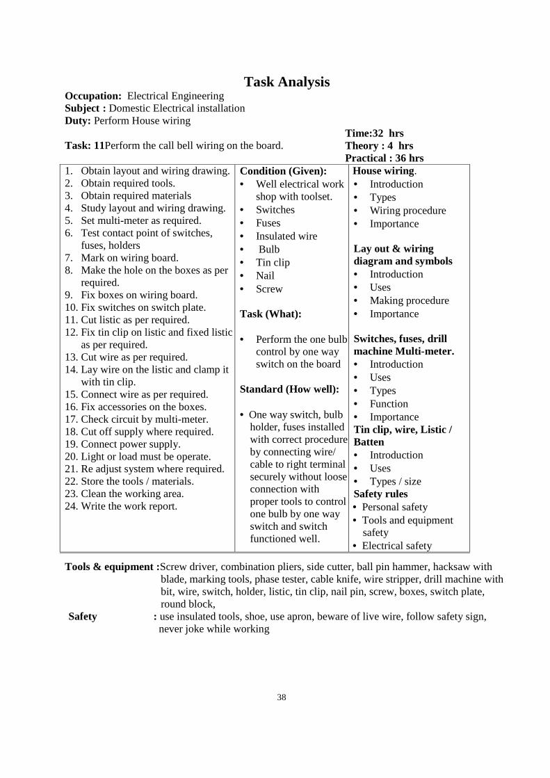
Task Analysis Occupation: Electrical Engineering Subject : Domestic Electrical installation Duty: Perform House wiring Task: 11Perform the call bell wiring on the board.
Time:32 hrs Theory : 4 hrs Practical : 36 hrs
1. Obtain layout and wiring drawing. 2. Obtain required tools. 3. Obtain required materials 4. Study layout and wiring drawing. 5. Set multi-meter as required. 6. Test contact point of switches,
fuses, holders 7. Mark on wiring board. 8. Make the hole on the boxes as per
required. 9. Fix boxes on wiring board. 10. Fix switches on switch plate. 11. Cut listic as per required. 12. Fix tin clip on listic and fixed listic
as per required. 13. Cut wire as per required. 14. Lay wire on the listic and clamp it
with tin clip. 15. Connect wire as per required. 16. Fix accessories on the boxes. 17. Check circuit by multi-meter. 18. Cut off supply where required. 19. Connect power supply. 20. Light or load must be operate. 21. Re adjust system where required. 22. Store the tools / materials. 23. Clean the working area. 24. Write the work report.
Condition (Given): • Well electrical work
shop with toolset. • Switches • Fuses • Insulated wire • Bulb • Tin clip • Nail • Screw Task (What): • Perform the one bulb
control by one way switch on the board
Standard (How well): • One way switch, bulb
holder, fuses installed with correct procedure by connecting wire/ cable to right terminal securely without loose connection with proper tools to control one bulb by one way switch and switch functioned well.
House wiring. • Introduction • Types • Wiring procedure • Importance Lay out & wiring diagram and symbols • Introduction • Uses • Making procedure • Importance Switches, fuses, drill machine Multi-meter. • Introduction • Uses • Types • Function • Importance Tin clip, wire, Listic / Batten • Introduction • Uses • Types / size Safety rules • Personal safety • Tools and equipment
safety • Electrical safety
Tools & equipment :Screw driver, combination pliers, side cutter, ball pin hammer, hacksaw with blade, marking tools, phase tester, cable knife, wire stripper, drill machine with bit, wire, switch, holder, listic, tin clip, nail pin, screw, boxes, switch plate, round block,
Safety : use insulated tools, shoe, use apron, beware of live wire, follow safety sign, never joke while working
39
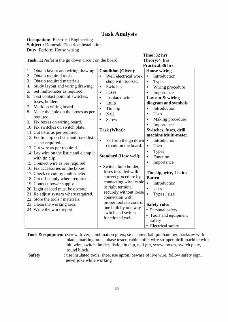
Task Analysis Occupation: Electrical Engineering Subject : Domestic Electrical installation Duty: Perform House wiring Task: 12Perform the go down circuit on the board.
Time :32 hrs Theory:4 hrs Practical:36 hrs
1. Obtain layout and wiring drawing. 2. Obtain required tools. 3. Obtain required materials 4. Study layout and wiring drawing. 5. Set multi-meter as required. 6. Test contact point of switches,
fuses, holders 7. Mark on wiring board. 8. Make the hole on the boxes as per
required. 9. Fix boxes on wiring board. 10. Fix switches on switch plate. 11. Cut listic as per required. 12. Fix tin clip on listic and fixed listic
as per required. 13. Cut wire as per required. 14. Lay wire on the listic and clamp it
with tin clip. 15. Connect wire as per required. 16. Fix accessories on the boxes. 17. Check circuit by multi-meter. 18. Cut off supply where required. 19. Connect power supply. 20. Light or load must be operate. 21. Re adjust system where required. 22. Store the tools / materials. 23. Clean the working area. 24. Write the work report.
Condition (Given): • Well electrical work
shop with toolset. • Switches • Fuses • Insulated wire • Bulb • Tin clip • Nail • Screw Task (What): • Perform the go down
circuit on the board. Standard (How well): • Switch, bulb holder,
fuses installed with correct procedure by connecting wire/ cable to right terminal securely without loose connection with proper tools to control one bulb by one way switch and switch functioned well.
House wiring. • Introduction • Types • Wiring procedure • Importance Lay out & wiring diagram and symbols • Introduction • Uses • Making procedure • Importance Switches, fuses, drill machine Multi-meter. • Introduction • Uses • Types • Function • Importance
Tin clip, wire, Listic / Batten • Introduction • Uses • Types / size Safety rules • Personal safety • Tools and equipment
safety • Electrical safety
Tools & equipment :Screw driver, combination pliers, side cutter, ball pin hammer, hacksaw with blade, marking tools, phase tester, cable knife, wire stripper, drill machine with bit, wire, switch, holder, listic, tin clip, nail pin, screw, boxes, switch plate, round block,
Safety : use insulated tools, shoe, use apron, beware of live wire, follow safety sign, never joke while working
40
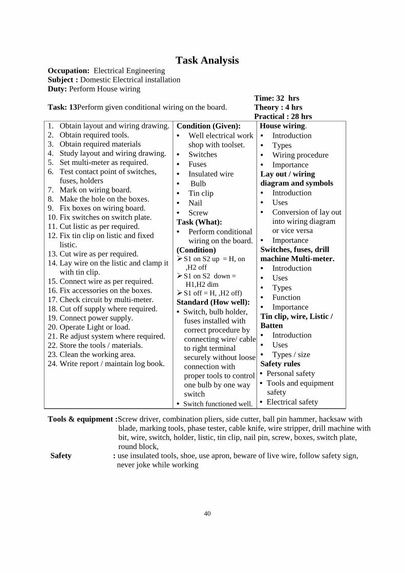
Task Analysis Occupation: Electrical Engineering Subject : Domestic Electrical installation Duty: Perform House wiring Task: 13Perform given conditional wiring on the board.
Time: 32 hrs Theory : 4 hrs Practical : 28 hrs
1. Obtain layout and wiring drawing. 2. Obtain required tools. 3. Obtain required materials 4. Study layout and wiring drawing. 5. Set multi-meter as required. 6. Test contact point of switches,
fuses, holders 7. Mark on wiring board. 8. Make the hole on the boxes. 9. Fix boxes on wiring board. 10. Fix switches on switch plate. 11. Cut listic as per required. 12. Fix tin clip on listic and fixed
listic. 13. Cut wire as per required. 14. Lay wire on the listic and clamp it
with tin clip. 15. Connect wire as per required. 16. Fix accessories on the boxes. 17. Check circuit by multi-meter. 18. Cut off supply where required. 19. Connect power supply. 20. Operate Light or load. 21. Re adjust system where required. 22. Store the tools / materials. 23. Clean the working area. 24. Write report / maintain log book.
Condition (Given): • Well electrical work
shop with toolset. • Switches • Fuses • Insulated wire • Bulb • Tin clip • Nail • Screw Task (What): • Perform conditional
wiring on the board. (Condition) S1 on S2 up = H, on
,H2 off S1 on S2 down =
H1,H2 dim S1 off = H, ,H2 off) Standard (How well): • Switch, bulb holder,
fuses installed with correct procedure by connecting wire/ cable to right terminal securely without loose connection with proper tools to control one bulb by one way switch
• Switch functioned well.
House wiring. • Introduction • Types • Wiring procedure • Importance Lay out / wiring diagram and symbols • Introduction • Uses • Conversion of lay out
into wiring diagram or vice versa
• Importance Switches, fuses, drill machine Multi-meter. • Introduction • Uses • Types • Function • Importance Tin clip, wire, Listic / Batten • Introduction • Uses • Types / size Safety rules • Personal safety • Tools and equipment
safety • Electrical safety
Tools & equipment :Screw driver, combination pliers, side cutter, ball pin hammer, hacksaw with blade, marking tools, phase tester, cable knife, wire stripper, drill machine with bit, wire, switch, holder, listic, tin clip, nail pin, screw, boxes, switch plate, round block,
Safety : use insulated tools, shoe, use apron, beware of live wire, follow safety sign, never joke while working
41
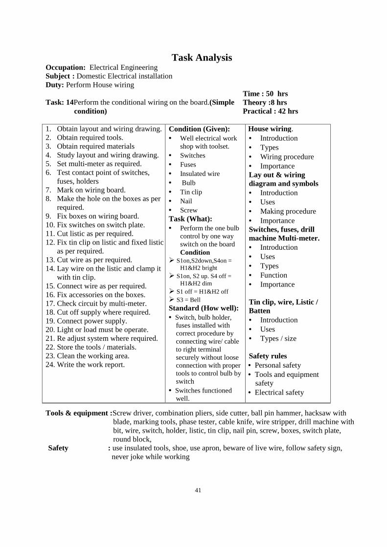
Task Analysis Occupation: Electrical Engineering Subject : Domestic Electrical installation Duty: Perform House wiring Task: 14Perform the conditional wiring on the board.(Simple
condition)
Time : 50 hrs Theory :8 hrs Practical : 42 hrs
1. Obtain layout and wiring drawing. 2. Obtain required tools. 3. Obtain required materials 4. Study layout and wiring drawing. 5. Set multi-meter as required. 6. Test contact point of switches,
fuses, holders 7. Mark on wiring board. 8. Make the hole on the boxes as per
required. 9. Fix boxes on wiring board. 10. Fix switches on switch plate. 11. Cut listic as per required. 12. Fix tin clip on listic and fixed listic
as per required. 13. Cut wire as per required. 14. Lay wire on the listic and clamp it
with tin clip. 15. Connect wire as per required. 16. Fix accessories on the boxes. 17. Check circuit by multi-meter. 18. Cut off supply where required. 19. Connect power supply. 20. Light or load must be operate. 21. Re adjust system where required. 22. Store the tools / materials. 23. Clean the working area. 24. Write the work report.
Condition (Given): • Well electrical work
shop with toolset. • Switches • Fuses • Insulated wire • Bulb • Tin clip • Nail • Screw Task (What): • Perform the one bulb
control by one way switch on the board Condition
S1on,S2down,S4on = H1&H2 bright
S1on, S2 up. S4 off = H1&H2 dim
S1 off = H1&H2 off S3 = Bell Standard (How well): • Switch, bulb holder,
fuses installed with correct procedure by connecting wire/ cable to right terminal securely without loose connection with proper tools to control bulb by switch
• Switches functioned well.
House wiring. • Introduction • Types • Wiring procedure • Importance Lay out & wiring diagram and symbols • Introduction • Uses • Making procedure • Importance Switches, fuses, drill machine Multi-meter. • Introduction • Uses • Types • Function • Importance
Tin clip, wire, Listic / Batten • Introduction • Uses • Types / size Safety rules • Personal safety • Tools and equipment
safety • Electrical safety
Tools & equipment :Screw driver, combination pliers, side cutter, ball pin hammer, hacksaw with blade, marking tools, phase tester, cable knife, wire stripper, drill machine with bit, wire, switch, holder, listic, tin clip, nail pin, screw, boxes, switch plate, round block,
Safety : use insulated tools, shoe, use apron, beware of live wire, follow safety sign, never joke while working
42
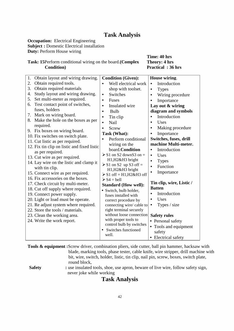
Task Analysis Occupation: Electrical Engineering Subject : Domestic Electrical installation Duty: Perform House wiring Task: 15Perform conditional wiring on the board.(Complex
Condition)
Time: 40 hrs Theory: 4 hrs Practical : 36 hrs
1. Obtain layout and wiring drawing. 2. Obtain required tools. 3. Obtain required materials 4. Study layout and wiring drawing. 5. Set multi-meter as required. 6. Test contact point of switches,
fuses, holders 7. Mark on wiring board. 8. Make the hole on the boxes as per
required. 9. Fix boxes on wiring board. 10. Fix switches on switch plate. 11. Cut listic as per required. 12. Fix tin clip on listic and fixed listic
as per required. 13. Cut wire as per required. 14. Lay wire on the listic and clamp it
with tin clip. 15. Connect wire as per required. 16. Fix accessories on the boxes. 17. Check circuit by multi-meter. 18. Cut off supply where required. 19. Connect power supply. 20. Light or load must be operate. 21. Re adjust system where required. 22. Store the tools / materials. 23. Clean the working area. 24. Write the work report.
Condition (Given): • Well electrical work
shop with toolset. • Switches • Fuses • Insulated wire • Bulb • Tin clip • Nail • Screw Task (What): • Perform conditional
wiring on the board.Condition
S1 on S2 downS3 on = H1,H2&H3 bright
S1 on S2 up S3 off = H1,H2&H3 bright
S1 off = H1,H2&H3 off S4 = bell Standard (How well): • Switch, bulb holder,
fuses installed with correct procedure by connecting wire/ cable to right terminal securely without loose connection with proper tools to control bulb by switches
• Switches functioned well.
House wiring. • Introduction • Types • Wiring procedure • Importance Lay out & wiring diagram and symbols • Introduction • Uses • Making procedure • Importance Switches, fuses, drill machine Multi-meter. • Introduction • Uses • Types • Function • Importance
Tin clip, wire, Listic / Batten • Introduction • Uses • Types / size Safety rules • Personal safety • Tools and equipment
safety • Electrical safety
Tools & equipment :Screw driver, combination pliers, side cutter, ball pin hammer, hacksaw with blade, marking tools, phase tester, cable knife, wire stripper, drill machine with bit, wire, switch, holder, listic, tin clip, nail pin, screw, boxes, switch plate, round block,
Safety : use insulated tools, shoe, use apron, beware of live wire, follow safety sign, never joke while working
Task Analysis
43
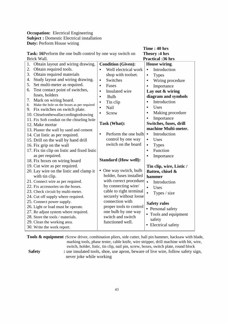
Occupation: Electrical Engineering Subject : Domestic Electrical installation Duty: Perform House wiring Task: 16Perform the one bulb control by one way switch on Brick Wall.
Time : 40 hrs Theory :4 hrs Practical :36 hrs
1. Obtain layout and wiring drawing. 2. Obtain required tools. 3. Obtain required materials 4. Study layout and wiring drawing. 5. Set multi-meter as required. 6. Test contact point of switches,
fuses, holders 7. Mark on wiring board. 8. Make the hole on the boxes as per required 9. Fix switches on switch plate. 10. Chiselonthewallaccordingtodrawing 11. Fix Soft conduit on the chiseling hole 12. Make mortar 13. Plaster the wall by sand and cement 14. Cut listic as per required. 15. Drill on the wall by hand drill 16. Fix grip on the wall 17. Fix tin clip on listic and fixed listic
as per required. 18. Fix boxes on wiring board 19. Cut wire as per required. 20. Lay wire on the listic and clamp it
with tin clip. 21. Connect wire as per required. 22. Fix accessories on the boxes. 23. Check circuit by multi-meter. 24. Cut off supply where required. 25. Connect power supply. 26. Light or load must be operate. 27. Re adjust system where required. 28. Store the tools / materials. 29. Clean the working area. 30. Write the work report.
Condition (Given): • Well electrical work
shop with toolset. • Switches • Fuses • Insulated wire • Bulb • Tin clip • Nail • Screw Task (What): • Perform the one bulb
control by one way switch on the board
Standard (How well): • One way switch, bulb
holder, fuses installed with correct procedure by connecting wire/ cable to right terminal securely without loose connection with proper tools to control one bulb by one way switch and switch functioned well.
House wiring. • Introduction • Types • Wiring procedure • Importance Lay out & wiring diagram and symbols • Introduction • Uses • Making procedure • Importance Switches, fuses, drill machine Multi-meter. • Introduction • Uses • Types • Function • Importance
Tin clip, wire, Listic / Batten, chisel & hammer • Introduction • Uses • Types / size Safety rules • Personal safety • Tools and equipment
safety • Electrical safety
Tools & equipment :Screw driver, combination pliers, side cutter, ball pin hammer, hacksaw with blade, marking tools, phase tester, cable knife, wire stripper, drill machine with bit, wire, switch, holder, listic, tin clip, nail pin, screw, boxes, switch plate, round block
Safety : use insulated tools, shoe, use apron, beware of live wire, follow safety sign, never joke while working
44
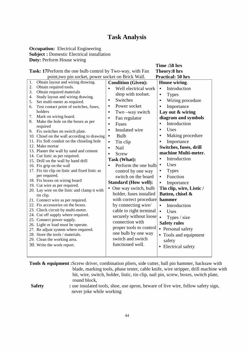
Task Analysis
Occupation: Electrical Engineering Subject : Domestic Electrical installation Duty: Perform House wiring Task: 17Perform the one bulb control by Two-way, with Fan
point,two pin socket, power socket on Brick Wall.
Time :58 hrs Theory:8 hrs Practical: 50 hrs
1. Obtain layout and wiring drawing. 2. Obtain required tools. 3. Obtain required materials 4. Study layout and wiring drawing. 5. Set multi-meter as required. 6. Test contact point of switches, fuses,
holders 7. Mark on wiring board. 8. Make the hole on the boxes as per
required 9. Fix switches on switch plate. 10. Chisel on the wall according to drawing 11. Fix Soft conduit on the chiseling hole 12. Make mortar 13. Plaster the wall by sand and cement 14. Cut listic as per required. 15. Drill on the wall by hand drill 16. Fix grip on the wall 17. Fix tin clip on listic and fixed listic as
per required. 18. Fix boxes on wiring board 19. Cut wire as per required. 20. Lay wire on the listic and clamp it with
tin clip. 21. Connect wire as per required. 22. Fix accessories on the boxes. 23. Check circuit by multi-meter. 24. Cut off supply where required. 25. Connect power supply. 26. Light or load must be operate. 27. Re adjust system where required. 28. Store the tools / materials. 29. Clean the working area. 30. Write the work report.
Condition (Given): • Well electrical work
shop with toolset. • Switches • Power socket • Two –way switch • Fan regulator • Fuses • Insulated wire • Bulb • Tin clip • Nail • Screw Task (What): • Perform the one bulb
control by one way switch on the board
Standard (How well): • One way switch, bulb
holder, fuses installed with correct procedure by connecting wire/ cable to right terminal securely without loose connection with proper tools to control one bulb by one way switch and switch functioned well.
House wiring. • Introduction • Types • Wiring procedure • Importance Lay out & wiring diagram and symbols • Introduction • Uses • Making procedure • Importance Switches, fuses, drill machine Multi-meter. • Introduction • Uses • Types • Function • Importance Tin clip, wire, Listic / Batten, chisel & hammer • Introduction • Uses • Types / size Safety rules • Personal safety • Tools and equipment
safety • Electrical safety
Tools & equipment :Screw driver, combination pliers, side cutter, ball pin hammer, hacksaw with blade, marking tools, phase tester, cable knife, wire stripper, drill machine with bit, wire, switch, holder, listic, tin clip, nail pin, screw, boxes, switch plate, round block,
Safety : use insulated tools, shoe, use apron, beware of live wire, follow safety sign, never joke while working
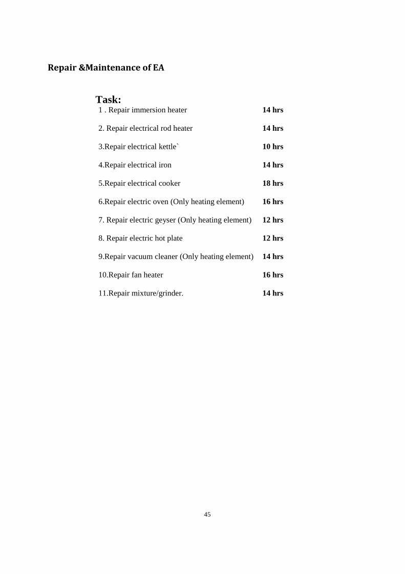
45
Repair &Maintenance of EA
Task: 1 . Repair immersion heater 14 hrs
2. Repair electrical rod heater 14 hrs
3.Repair electrical kettle` 10 hrs
4.Repair electrical iron 14 hrs
5.Repair electrical cooker 18 hrs
6.Repair electric oven (Only heating element) 16 hrs
7. Repair electric geyser (Only heating element) 12 hrs
8. Repair electric hot plate 12 hrs
9.Repair vacuum cleaner (Only heating element) 14 hrs
10.Repair fan heater 16 hrs
11.Repair mixture/grinder. 14 hrs
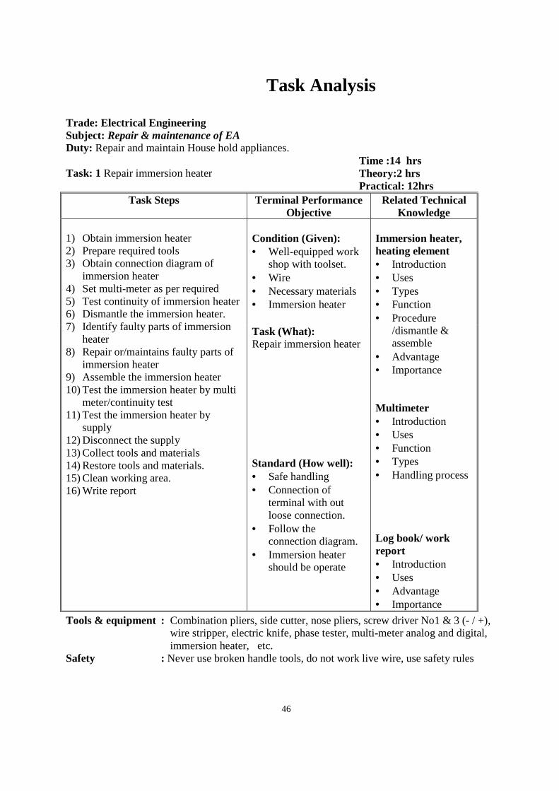
46
Task Analysis
Trade: Electrical Engineering Subject: Repair & maintenance of EA
Duty: Repair and maintain House hold appliances. Task: 1 Repair immersion heater
Time :14 hrs Theory:2 hrs Practical: 12hrs
Task Steps Terminal Performance Objective
Related Technical Knowledge
1) Obtain immersion heater 2) Prepare required tools 3) Obtain connection diagram of
immersion heater 4) Set multi-meter as per required 5) Test continuity of immersion heater 6) Dismantle the immersion heater. 7) Identify faulty parts of immersion
heater 8) Repair or/maintains faulty parts of
immersion heater 9) Assemble the immersion heater 10) Test the immersion heater by multi
meter/continuity test 11) Test the immersion heater by
supply 12) Disconnect the supply 13) Collect tools and materials 14) Restore tools and materials. 15) Clean working area. 16) Write report
Condition (Given): • Well-equipped work
shop with toolset. • Wire • Necessary materials • Immersion heater
Immersion heater, heating element • Introduction • Uses • Types • Function • Procedure
/dismantle & assemble
• Advantage • Importance Multimeter • Introduction • Uses • Function • Types • Handling process Log book/ work report • Introduction • Uses • Advantage • Importance
Task (What): Repair immersion heater
Standard (How well): • Safe handling • Connection of
terminal with out loose connection.
• Follow the connection diagram.
• Immersion heater should be operate
Tools & equipment : Combination pliers, side cutter, nose pliers, screw driver No1 & 3 (- / +), wire stripper, electric knife, phase tester, multi-meter analog and digital, immersion heater, etc.
Safety : Never use broken handle tools, do not work live wire, use safety rules
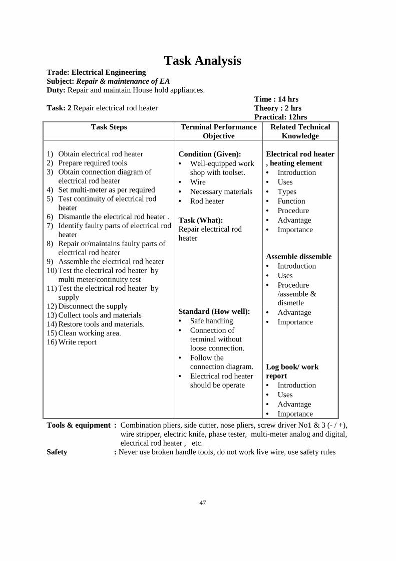
47
Task Analysis Trade: Electrical Engineering Subject: Repair & maintenance of EA
Duty: Repair and maintain House hold appliances. Task: 2 Repair electrical rod heater
Time : 14 hrs Theory : 2 hrs Practical: 12hrs
Task Steps Terminal Performance Objective
Related Technical Knowledge
1) Obtain electrical rod heater 2) Prepare required tools 3) Obtain connection diagram of
electrical rod heater 4) Set multi-meter as per required 5) Test continuity of electrical rod
heater 6) Dismantle the electrical rod heater . 7) Identify faulty parts of electrical rod
heater 8) Repair or/maintains faulty parts of
electrical rod heater 9) Assemble the electrical rod heater 10) Test the electrical rod heater by
multi meter/continuity test 11) Test the electrical rod heater by
supply 12) Disconnect the supply 13) Collect tools and materials 14) Restore tools and materials. 15) Clean working area. 16) Write report
Condition (Given): • Well-equipped work
shop with toolset. • Wire • Necessary materials • Rod heater
Electrical rod heater , heating element • Introduction • Uses • Types • Function • Procedure • Advantage • Importance Assemble dissemble • Introduction • Uses • Procedure
/assemble & dismetle
• Advantage • Importance Log book/ work report • Introduction • Uses • Advantage • Importance
Task (What): Repair electrical rod heater
Standard (How well): • Safe handling • Connection of
terminal without loose connection.
• Follow the connection diagram.
• Electrical rod heater should be operate
Tools & equipment : Combination pliers, side cutter, nose pliers, screw driver No1 & 3 (- / +), wire stripper, electric knife, phase tester, multi-meter analog and digital, electrical rod heater , etc.
Safety : Never use broken handle tools, do not work live wire, use safety rules
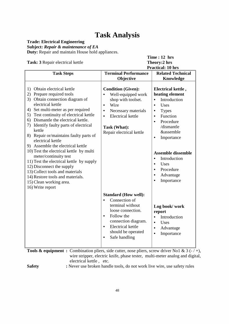
48
Task Analysis Trade: Electrical Engineering Subject: Repair & maintenance of EA
Duty: Repair and maintain House hold appliances. Task: 3 Repair electrical kettle
Time : 12 hrs Theory:2 hrs Practical: 10 hrs
Task Steps Terminal Performance Objective
Related Technical Knowledge
1) Obtain electrical kettle 2) Prepare required tools 3) Obtain connection diagram of
electrical kettle 4) Set multi-meter as per required 5) Test continuity of electrical kettle 6) Dismantle the electrical kettle. 7) Identify faulty parts of electrical
kettle 8) Repair or/maintains faulty parts of
electrical kettle 9) Assemble the electrical kettle 10) Test the electrical kettle by multi
meter/continuity test 11) Test the electrical kettle by supply 12) Disconnect the supply 13) Collect tools and materials 14) Restore tools and materials. 15) Clean working area. 16) Write report
Condition (Given): • Well-equipped work
shop with toolset. • Wire • Necessary materials • Electrical kettle
Electrical kettle , heating element • Introduction • Uses • Types • Function • Procedure
/dismantle &assemble
• Importance Assemble dissemble • Introduction • Uses • Procedure • Advantage • Importance Log book/ work report • Introduction • Uses • Advantage • Importance
Task (What): Repair electrical kettle
Standard (How well): • Connection of
terminal without loose connection.
• Follow the connection diagram.
• Electrical kettle should be operated
• Safe handling
Tools & equipment : Combination pliers, side cutter, nose pliers, screw driver No1 & 3 (- / +), wire stripper, electric knife, phase tester, multi-meter analog and digital, electrical kettle , etc.
Safety : Never use broken handle tools, do not work live wire, use safety rules
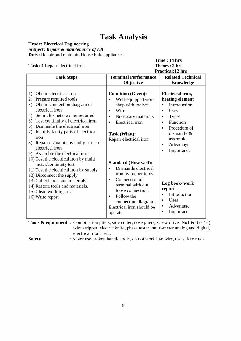
49
Task Analysis Trade: Electrical Engineering Subject: Repair & maintenance of EA
Duty: Repair and maintain House hold appliances. Task: 4 Repair electrical iron
Time : 14 hrs Theory: 2 hrs Practical:12 hrs
Task Steps Terminal Performance Objective
Related Technical Knowledge
1) Obtain electrical iron 2) Prepare required tools 3) Obtain connection diagram of
electrical iron 4) Set multi-meter as per required 5) Test continuity of electrical iron 6) Dismantle the electrical iron. 7) Identify faulty parts of electrical
iron 8) Repair or/maintains faulty parts of
electrical iron 9) Assemble the electrical iron 10) Test the electrical iron by multi
meter/continuity test 11) Test the electrical iron by supply 12) Disconnect the supply 13) Collect tools and materials 14) Restore tools and materials. 15) Clean working area. 16) Write report
Condition (Given): • Well-equipped work
shop with toolset. • Wire • Necessary materials • Electrical iron
Electrical iron, heating element • Introduction • Uses • Types • Function • Procedure of
dismantle & assemble
• Advantage • Importance Log book/ work report • Introduction • Uses • Advantage • Importance
Task (What): Repair electrical iron
Standard (How well): • Dismantle electrical
iron by proper tools. • Connection of
terminal with out loose connection.
• Follow the connection diagram.
Electrical iron should be operate
Tools & equipment : Combination pliers, side cutter, nose pliers, screw driver No1 & 3 (- / +), wire stripper, electric knife, phase tester, multi-meter analog and digital, electrical iron, etc.
Safety : Never use broken handle tools, do not work live wire, use safety rules
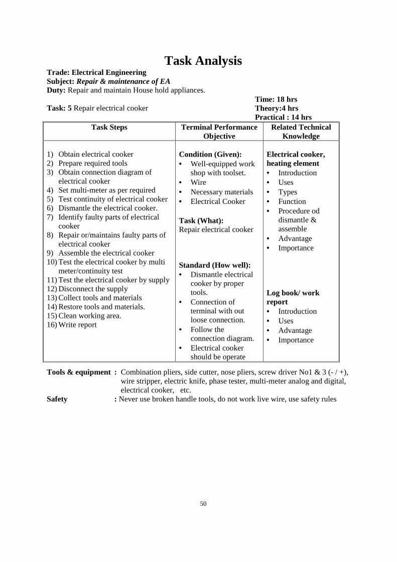
50
Task Analysis Trade: Electrical Engineering Subject: Repair & maintenance of EA
Duty: Repair and maintain House hold appliances. Task: 5 Repair electrical cooker
Time: 18 hrs Theory:4 hrs Practical : 14 hrs
Task Steps Terminal Performance Objective
Related Technical Knowledge
1) Obtain electrical cooker 2) Prepare required tools 3) Obtain connection diagram of
electrical cooker 4) Set multi-meter as per required 5) Test continuity of electrical cooker 6) Dismantle the electrical cooker. 7) Identify faulty parts of electrical
cooker 8) Repair or/maintains faulty parts of
electrical cooker 9) Assemble the electrical cooker 10) Test the electrical cooker by multi
meter/continuity test 11) Test the electrical cooker by supply 12) Disconnect the supply 13) Collect tools and materials 14) Restore tools and materials. 15) Clean working area. 16) Write report
Condition (Given): • Well-equipped work
shop with toolset. • Wire • Necessary materials • Electrical Cooker
Electrical cooker, heating element • Introduction • Uses • Types • Function • Procedure od
dismantle & assemble
• Advantage • Importance Log book/ work report • Introduction • Uses • Advantage • Importance
Task (What): Repair electrical cooker
Standard (How well): • Dismantle electrical
cooker by proper tools.
• Connection of terminal with out loose connection.
• Follow the connection diagram.
• Electrical cooker should be operate
Tools & equipment : Combination pliers, side cutter, nose pliers, screw driver No1 & 3 (- / +), wire stripper, electric knife, phase tester, multi-meter analog and digital, electrical cooker, etc.
Safety : Never use broken handle tools, do not work live wire, use safety rules
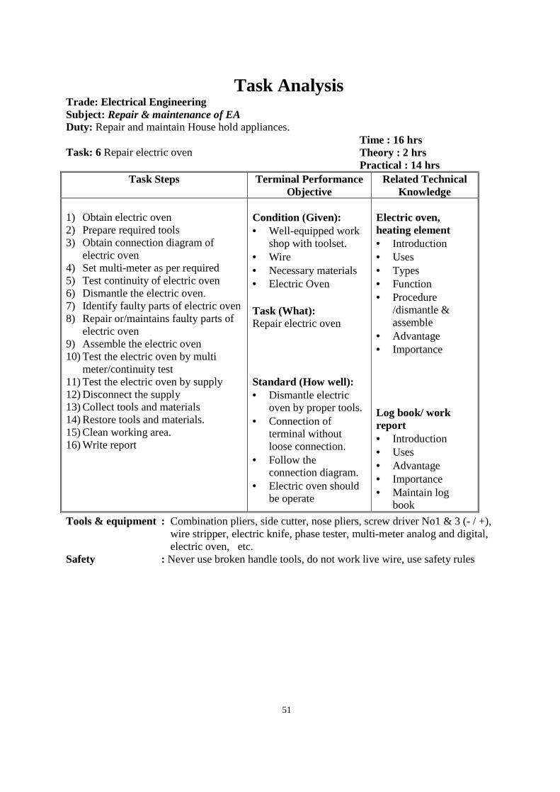
51
Task Analysis Trade: Electrical Engineering Subject: Repair & maintenance of EA
Duty: Repair and maintain House hold appliances. Task: 6 Repair electric oven
Time : 16 hrs Theory : 2 hrs Practical : 14 hrs
Task Steps Terminal Performance Objective
Related Technical Knowledge
1) Obtain electric oven 2) Prepare required tools 3) Obtain connection diagram of
electric oven 4) Set multi-meter as per required 5) Test continuity of electric oven 6) Dismantle the electric oven. 7) Identify faulty parts of electric oven 8) Repair or/maintains faulty parts of
electric oven 9) Assemble the electric oven 10) Test the electric oven by multi
meter/continuity test 11) Test the electric oven by supply 12) Disconnect the supply 13) Collect tools and materials 14) Restore tools and materials. 15) Clean working area. 16) Write report
Condition (Given): • Well-equipped work
shop with toolset. • Wire • Necessary materials • Electric Oven
Electric oven, heating element • Introduction • Uses • Types • Function • Procedure
/dismantle & assemble
• Advantage • Importance Log book/ work report • Introduction • Uses • Advantage • Importance • Maintain log
book
Task (What): Repair electric oven
Standard (How well): • Dismantle electric
oven by proper tools. • Connection of
terminal without loose connection.
• Follow the connection diagram.
• Electric oven should be operate
Tools & equipment : Combination pliers, side cutter, nose pliers, screw driver No1 & 3 (- / +), wire stripper, electric knife, phase tester, multi-meter analog and digital, electric oven, etc.
Safety : Never use broken handle tools, do not work live wire, use safety rules

52
Task Analysis Trade: Electrical Engineering Subject: Repair & maintenance of EA
Duty: Repair and maintain House hold appliances. Task: 7 Repair electric geyser
Time: 12 hrs Theory: 2 hrs Practical : 10 hrs
Task Steps Terminal Performance Objective
Related Technical Knowledge
1) Obtain electric geyser 2) Prepare required tools 3) Obtain connection diagram of
electric geyser 4) Set multi-meter as per required 5) Test continuity of electric geyser 6) Dismantle the electric geyser 7) Identify faulty parts of electric
geyser 8) Repair or/maintains faulty parts of
electric geyser 9) Assemble the electric geyser 10) Test the electric geyser by multi
meter/continuity test 11) Test the electric geyser by supply 12) Disconnect the supply 13) Collect tools and materials 14) Restore tools and materials. 15) Clean working area. 16) Write report
Condition (Given): • Well-equipped work
shop with toolset. • Wire • Necessary materials • Electric geyser
Electric geaser, heating element • Introduction • Uses • Types • Function • Procedure
/assemble & dismentle
• Advantage • Importance Log book/ work report • Introduction • Uses • Advantage • Importance
Task (What): Repair electric geyser
Standard (How well): • Dismantle electric
geyser by proper tools.
• Connection of terminal without loose connection.
• Follow the connection diagram.
• Electric geyser should be operate
Tools & equipment : Combination pliers, side cutter, nose pliers, screw driver No1 & 3 (- / +), wire stripper, electric knife, phase tester, multi-meter analog and digital, electric geyser, etc.
Safety : Never use broken handle tools, do not work live wire, use safety rules
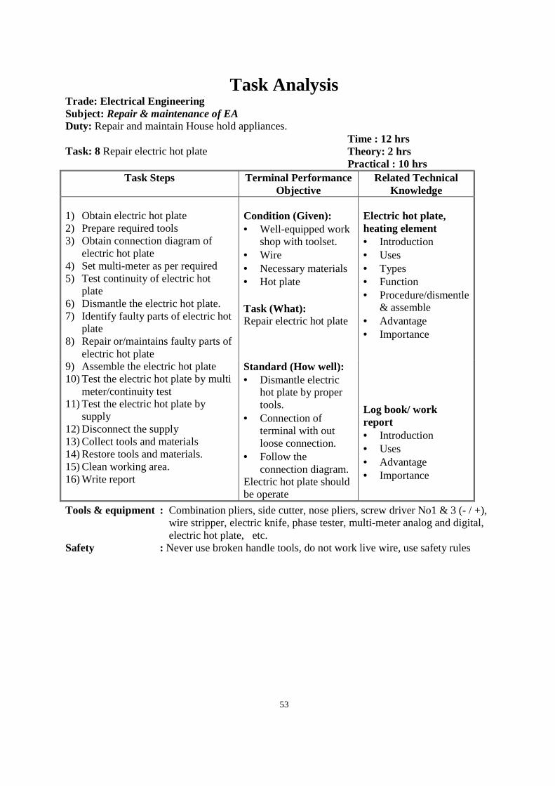
53
Task Analysis Trade: Electrical Engineering Subject: Repair & maintenance of EA
Duty: Repair and maintain House hold appliances. Task: 8 Repair electric hot plate
Time : 12 hrs Theory: 2 hrs Practical : 10 hrs
Task Steps Terminal Performance Objective
Related Technical Knowledge
1) Obtain electric hot plate 2) Prepare required tools 3) Obtain connection diagram of
electric hot plate 4) Set multi-meter as per required 5) Test continuity of electric hot
plate 6) Dismantle the electric hot plate. 7) Identify faulty parts of electric hot
plate 8) Repair or/maintains faulty parts of
electric hot plate 9) Assemble the electric hot plate 10) Test the electric hot plate by multi
meter/continuity test 11) Test the electric hot plate by
supply 12) Disconnect the supply 13) Collect tools and materials 14) Restore tools and materials. 15) Clean working area. 16) Write report
Condition (Given): • Well-equipped work
shop with toolset. • Wire • Necessary materials • Hot plate
Electric hot plate, heating element • Introduction • Uses • Types • Function • Procedure/dismentle
& assemble • Advantage • Importance Log book/ work report • Introduction • Uses • Advantage • Importance
Task (What): Repair electric hot plate
Standard (How well): • Dismantle electric
hot plate by proper tools.
• Connection of terminal with out loose connection.
• Follow the connection diagram.
Electric hot plate should be operate
Tools & equipment : Combination pliers, side cutter, nose pliers, screw driver No1 & 3 (- / +), wire stripper, electric knife, phase tester, multi-meter analog and digital, electric hot plate, etc.
Safety : Never use broken handle tools, do not work live wire, use safety rules
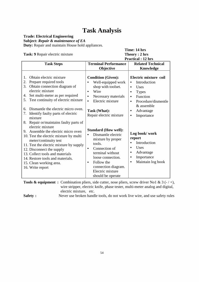
54
Task Analysis Trade: Electrical Engineering Subject: Repair & maintenance of EA
Duty: Repair and maintain House hold appliances. Task: 9 Repair electric mixture
Time: 14 hrs Theory : 2 hrs Practical : 12 hrs
Task Steps Terminal Performance Objective
Related Technical Knowledge
1. Obtain electric mixture 2. Prepare required tools 3. Obtain connection diagram of
electric mixture 4. Set multi-meter as per required 5. Test continuity of electric mixture
6. Dismantle the electric micro oven. 7. Identify faulty parts of electric
mixture 8. Repair or/maintains faulty parts of
electric mixture 9. Assemble the electric micro oven 10. Test the electric mixture by multi
meter/continuity test 11. Test the electric mixture by supply 12. Disconnect the supply 13. Collect tools and materials 14. Restore tools and materials. 15. Clean working area. 16. Write report
Condition (Given): • Well-equipped work
shop with toolset. • Wire • Necessary materials • Electric mixture
Electric mixture coil • Introduction • Uses • Types • Function • Procedure/dismentle
& assemble • Advantage • Importance Log book/ work report • Introduction • Uses • Advantage • Importance • Maintain log book
Task (What): Repair electric mixture
Standard (How well): • Dismantle electric
mixture by proper tools.
• Connection of terminal without loose connection.
• Follow the connection diagram. Electric mixture should be operate
Tools & equipment : Combination pliers, side cutter, nose pliers, screw driver No1 & 3 (- / +), wire stripper, electric knife, phase tester, multi-meter analog and digital, electric mixture, etc.
Safety : Never use broken handle tools, do not work live wire, and use safety rules
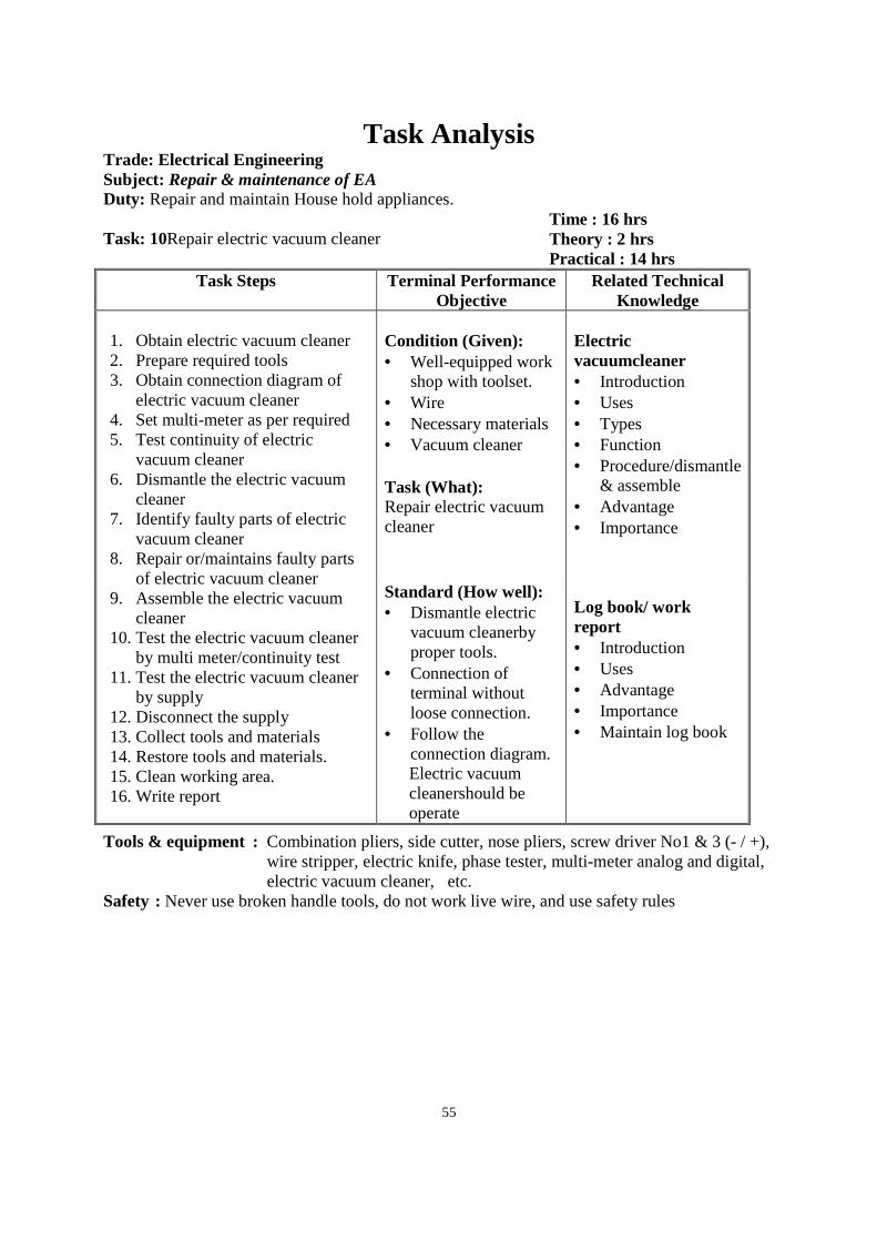
55
Task Analysis Trade: Electrical Engineering Subject: Repair & maintenance of EA
Duty: Repair and maintain House hold appliances. Task: 10Repair electric vacuum cleaner
Time : 16 hrs Theory : 2 hrs Practical : 14 hrs
Task Steps Terminal Performance Objective
Related Technical Knowledge
1. Obtain electric vacuum cleaner 2. Prepare required tools 3. Obtain connection diagram of
electric vacuum cleaner 4. Set multi-meter as per required 5. Test continuity of electric
vacuum cleaner 6. Dismantle the electric vacuum
cleaner 7. Identify faulty parts of electric
vacuum cleaner 8. Repair or/maintains faulty parts
of electric vacuum cleaner 9. Assemble the electric vacuum
cleaner 10. Test the electric vacuum cleaner
by multi meter/continuity test 11. Test the electric vacuum cleaner
by supply 12. Disconnect the supply 13. Collect tools and materials 14. Restore tools and materials. 15. Clean working area. 16. Write report
Condition (Given): • Well-equipped work
shop with toolset. • Wire • Necessary materials • Vacuum cleaner
Electric vacuumcleaner • Introduction • Uses • Types • Function • Procedure/dismantle
& assemble • Advantage • Importance Log book/ work report • Introduction • Uses • Advantage • Importance • Maintain log book
Task (What): Repair electric vacuum cleaner
Standard (How well): • Dismantle electric
vacuum cleanerby proper tools.
• Connection of terminal without loose connection.
• Follow the connection diagram. Electric vacuum cleanershould be operate
Tools & equipment : Combination pliers, side cutter, nose pliers, screw driver No1 & 3 (- / +), wire stripper, electric knife, phase tester, multi-meter analog and digital, electric vacuum cleaner, etc.
Safety : Never use broken handle tools, do not work live wire, and use safety rules
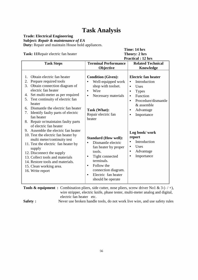
56
Task Analysis Trade: Electrical Engineering Subject: Repair & maintenance of EA
Duty: Repair and maintain House hold appliances. Task: 11Repair electric fan heater
Time: 14 hrs Theory: 2 hrs Practical : 12 hrs
Task Steps Terminal Performance Objective
Related Technical Knowledge
1. Obtain electric fan heater 2. Prepare required tools 3. Obtain connection diagram of
electric fan heater 4. Set multi-meter as per required 5. Test continuity of electric fan
heater 6. Dismantle the electric fan heater 7. Identify faulty parts of electric
fan heater 8. Repair or/maintains faulty parts
of electric fan heater 9. Assemble the electric fan heater 10. Test the electric fan heater by
multi meter/continuity test 11. Test the electric fan heater by
supply 12. Disconnect the supply 13. Collect tools and materials 14. Restore tools and materials. 15. Clean working area. 16. Write report
Condition (Given): • Well-equipped work
shop with toolset. • Wire • Necessary materials
Electric fan heater • Introduction • Uses • Types • Function • Procedure/dismantle
& assemble • Advantage • Importance Log book/ work report • Introduction • Uses • Advantage • Importance
Task (What): Repair electric fan heater
Standard (How well): • Dismantle electric
fan heater by proper tools.
• Tight connected terminals.
• Follow the connection diagram.
• Electric fan heater should be operate
Tools & equipment : Combination pliers, side cutter, nose pliers, screw driver No1 & 3 (- / +), wire stripper, electric knife, phase tester, multi-meter analog and digital, electric fan heater etc.
Safety : Never use broken handle tools, do not work live wire, and use safety rules
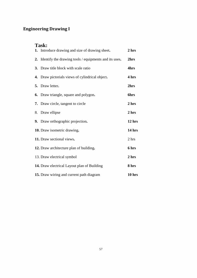
57
Engineering Drawing I
Task: 1. Introduce drawing and size of drawing sheet. 2 hrs
2. Identify the drawing tools / equipments and its uses. 2hrs
3. Draw title block with scale ratio 4hrs
4. Draw pictorials views of cylindrical object. 4 hrs
5. Draw letter. 2hrs
6. Draw triangle, square and polygon. 6hrs
7. Draw circle, tangent to circle 2 hrs
8. Draw ellipse 2 hrs
9. Draw orthographic projection. 12 hrs
10. Draw isometric drawing. 14 hrs
11. Draw sectional views. 2 hrs
12. Draw architecture plan of building. 6 hrs
13. Draw electrical symbol 2 hrs
14. Draw electrical Layout plan of Building 8 hrs
15. Draw wiring and current path diagram 10 hrs
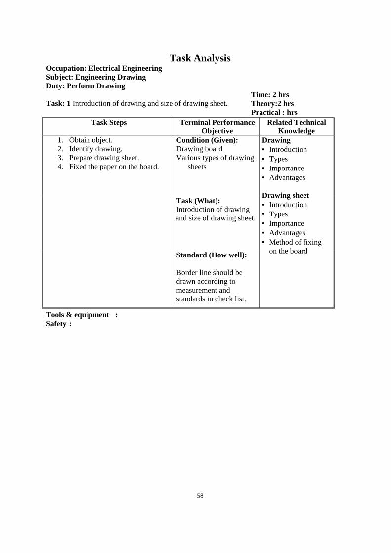
58
Task Analysis Occupation: Electrical Engineering Subject: Engineering Drawing Duty: Perform Drawing Task: 1 Introduction of drawing and size of drawing sheet.
Time: 2 hrs Theory:2 hrs Practical : hrs
Task Steps Terminal Performance Objective
Related Technical Knowledge
1. Obtain object. 2. Identify drawing. 3. Prepare drawing sheet. 4. Fixed the paper on the board.
Condition (Given): Drawing board Various types of drawing
sheets
Drawing • Introduction • Types • Importance • Advantages Drawing sheet • Introduction • Types • Importance • Advantages • Method of fixing
on the board
Task (What): Introduction of drawing and size of drawing sheet.
Standard (How well): Border line should be drawn according to measurement and standards in check list.
Tools & equipment : Safety :
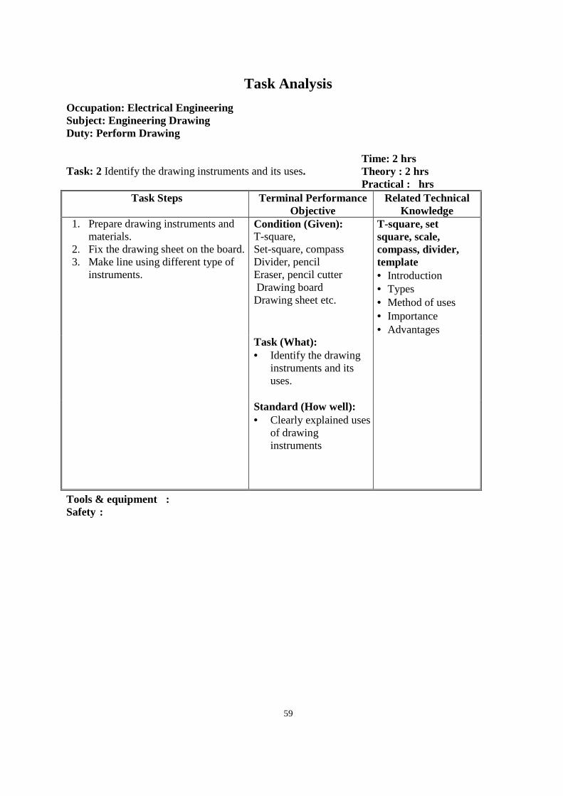
59
Task Analysis
Occupation: Electrical Engineering Subject: Engineering Drawing Duty: Perform Drawing Task: 2 Identify the drawing instruments and its uses.
Time: 2 hrs Theory : 2 hrs Practical : hrs
Task Steps Terminal Performance Objective
Related Technical Knowledge
1. Prepare drawing instruments and materials.
2. Fix the drawing sheet on the board. 3. Make line using different type of
instruments.
Condition (Given): T-square, Set-square, compass Divider, pencil Eraser, pencil cutter Drawing board Drawing sheet etc.
T-square, set square, scale, compass, divider, template • Introduction • Types • Method of uses • Importance • Advantages
Task (What): • Identify the drawing
instruments and its uses.
Standard (How well): • Clearly explained uses
of drawing instruments
Tools & equipment : Safety :
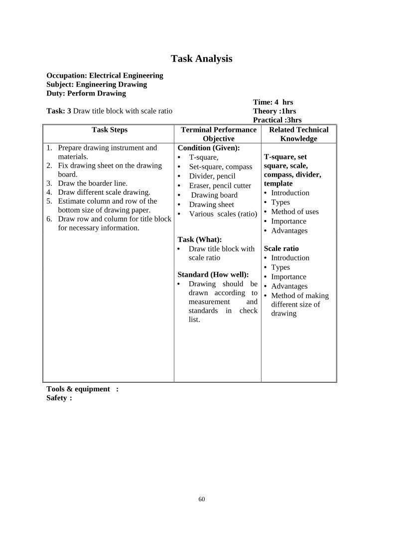
60
Task Analysis
Occupation: Electrical Engineering Subject: Engineering Drawing Duty: Perform Drawing Task: 3 Draw title block with scale ratio
Time: 4 hrs Theory :1hrs Practical :3hrs
Task Steps Terminal Performance Objective
Related Technical Knowledge
1. Prepare drawing instrument and materials.
2. Fix drawing sheet on the drawing board.
3. Draw the boarder line. 4. Draw different scale drawing. 5. Estimate column and row of the
bottom size of drawing paper. 6. Draw row and column for title block
for necessary information.
Condition (Given): • T-square, • Set-square, compass • Divider, pencil • Eraser, pencil cutter • Drawing board • Drawing sheet • Various scales (ratio)
T-square, set square, scale, compass, divider, template • Introduction • Types • Method of uses • Importance • Advantages Scale ratio • Introduction • Types • Importance • Advantages • Method of making
different size of drawing
Task (What): • Draw title block with
scale ratio
Standard (How well): • Drawing should be
drawn according to measurement and standards in check list.
Tools & equipment : Safety :
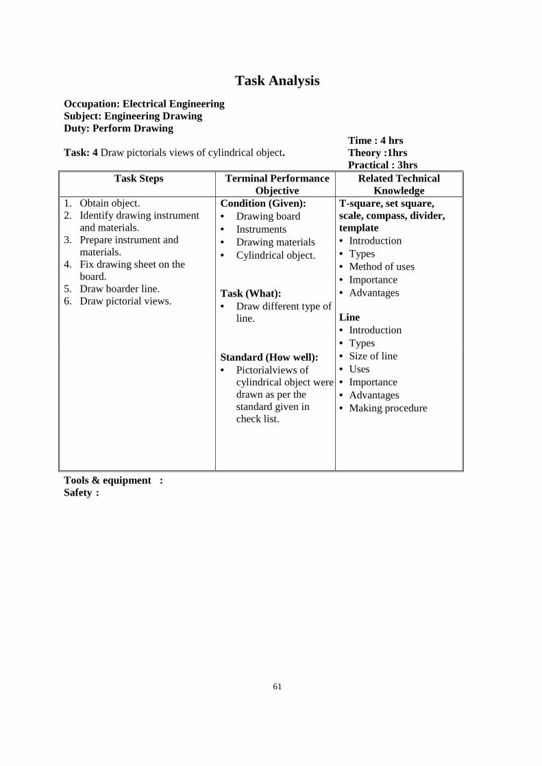
61
Task Analysis
Occupation: Electrical Engineering Subject: Engineering Drawing Duty: Perform Drawing Task: 4 Draw pictorials views of cylindrical object.
Time : 4 hrs Theory :1hrs Practical : 3hrs
Task Steps Terminal Performance Objective
Related Technical Knowledge
1. Obtain object. 2. Identify drawing instrument
and materials. 3. Prepare instrument and
materials. 4. Fix drawing sheet on the
board. 5. Draw boarder line. 6. Draw pictorial views.
Condition (Given): • Drawing board • Instruments • Drawing materials • Cylindrical object.
T-square, set square, scale, compass, divider, template • Introduction • Types • Method of uses • Importance • Advantages Line • Introduction • Types • Size of line • Uses • Importance • Advantages • Making procedure
Task (What): • Draw different type of
line.
Standard (How well): • Pictorialviews of
cylindrical object were drawn as per the standard given in check list.
Tools & equipment : Safety :
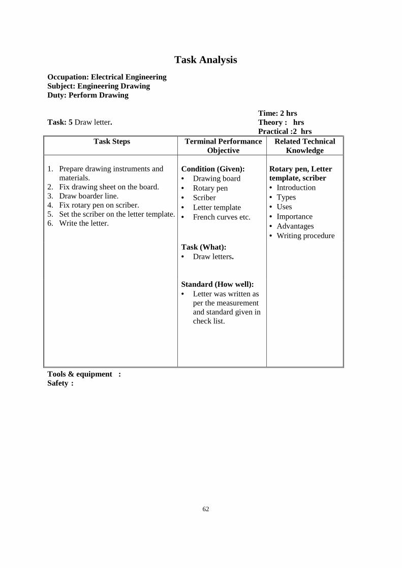
62
Task Analysis
Occupation: Electrical Engineering Subject: Engineering Drawing Duty: Perform Drawing Task: 5 Draw letter.
Time: 2 hrs Theory : hrs Practical :2 hrs
Task Steps Terminal Performance Objective
Related Technical Knowledge
1. Prepare drawing instruments and
materials. 2. Fix drawing sheet on the board. 3. Draw boarder line. 4. Fix rotary pen on scriber. 5. Set the scriber on the letter template. 6. Write the letter.
Condition (Given): • Drawing board • Rotary pen • Scriber • Letter template • French curves etc.
Rotary pen, Letter template, scriber • Introduction • Types • Uses • Importance • Advantages • Writing procedure
Task (What): • Draw letters.
Standard (How well): • Letter was written as
per the measurement and standard given in check list.
Tools & equipment : Safety :
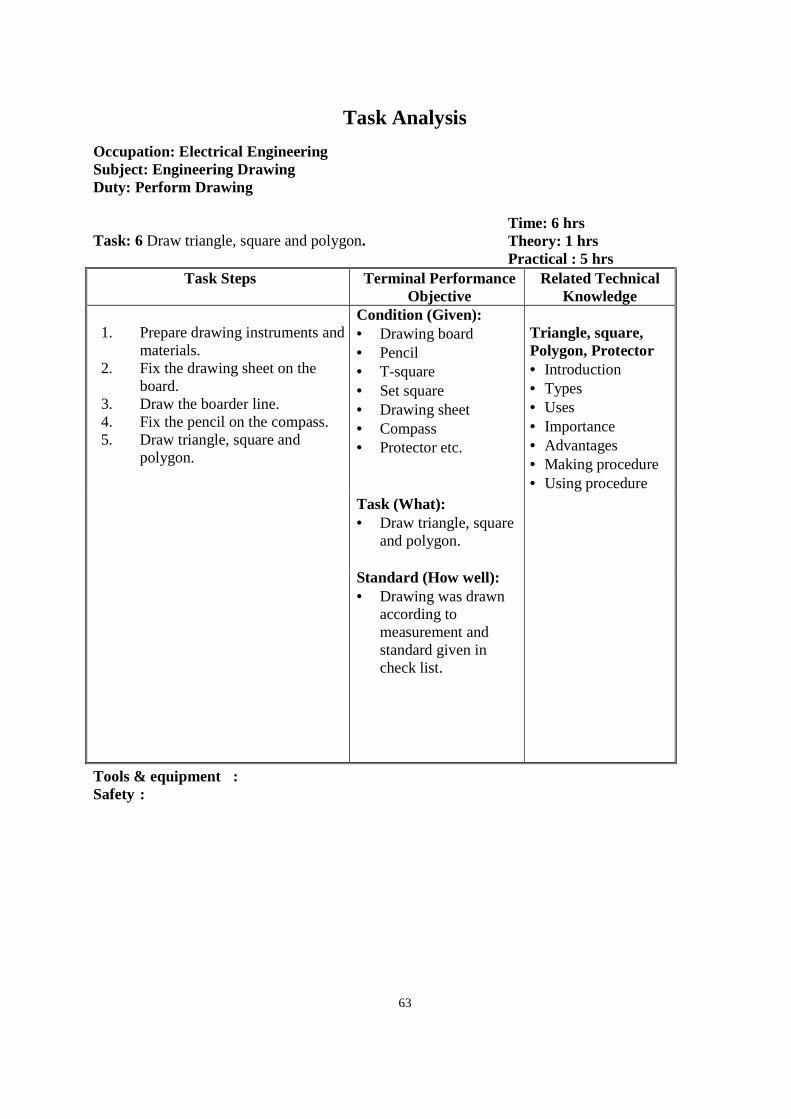
63
Task Analysis
Occupation: Electrical Engineering Subject: Engineering Drawing Duty: Perform Drawing Task: 6 Draw triangle, square and polygon.
Time: 6 hrs Theory: 1 hrs Practical : 5 hrs
Task Steps Terminal Performance Objective
Related Technical Knowledge
1. Prepare drawing instruments and
materials. 2. Fix the drawing sheet on the
board. 3. Draw the boarder line. 4. Fix the pencil on the compass. 5. Draw triangle, square and
polygon.
Condition (Given): • Drawing board • Pencil • T-square • Set square • Drawing sheet • Compass • Protector etc.
Triangle, square, Polygon, Protector • Introduction • Types • Uses • Importance • Advantages • Making procedure • Using procedure
Task (What): • Draw triangle, square
and polygon.
Standard (How well): • Drawing was drawn
according to measurement and standard given in check list.
Tools & equipment : Safety :

64
Task Analysis
Occupation: Electrical Engineering Subject: Engineering Drawing Duty: Perform Drawing Task: 7 Draw circle, tangent to circle
Time: 2 hrs Theory: hrs Practical: 2 hrs
Task Steps Terminal Performance Objective
Related Technical Knowledge
1. Prepare instruments and materials.
2. Fix the drawing sheet on the board.
3. Draw the border line. 4. Fix the pencil on the compass. 5. Draw circle, tangent to circle.
Condition (Given): • Drawing board • Pencil • T-square • Set square • Drawing sheet • Compass • Protector etc.
Compass, circle • Introduction • Types • Uses • Importance • Advantages • Using procedure • Making procedure Task (What):
• Draw circle and tangent to circle.
Standard (How well): • Drawing was drawn
according to measurement and standard given in check list.
Tools & equipment : Safety :
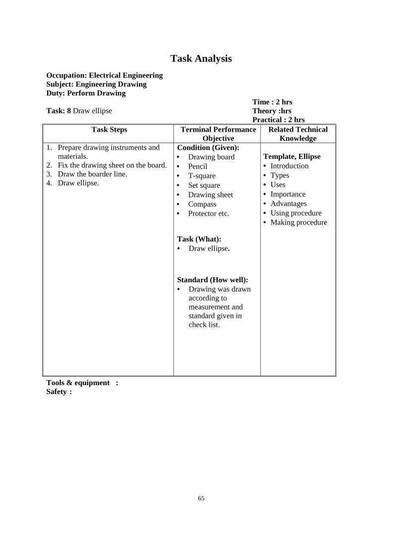
65
Task Analysis
Occupation: Electrical Engineering Subject: Engineering Drawing Duty: Perform Drawing Task: 8 Draw ellipse
Time : 2 hrs Theory :hrs Practical : 2 hrs
Task Steps Terminal Performance Objective
Related Technical Knowledge
1. Prepare drawing instruments and materials.
2. Fix the drawing sheet on the board. 3. Draw the boarder line. 4. Draw ellipse.
Condition (Given): • Drawing board • Pencil • T-square • Set square • Drawing sheet • Compass • Protector etc.
Template, Ellipse • Introduction • Types • Uses • Importance • Advantages • Using procedure • Making procedure
Task (What): • Draw ellipse.
Standard (How well): • Drawing was drawn
according to measurement and standard given in check list.
Tools & equipment : Safety :
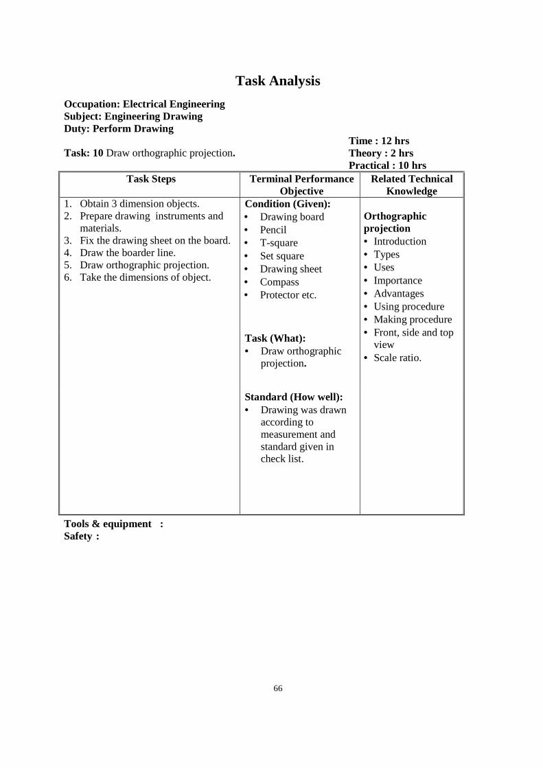
66
Task Analysis
Occupation: Electrical Engineering Subject: Engineering Drawing Duty: Perform Drawing Task: 10 Draw orthographic projection.
Time : 12 hrs Theory : 2 hrs Practical : 10 hrs
Task Steps Terminal Performance Objective
Related Technical Knowledge
1. Obtain 3 dimension objects. 2. Prepare drawing instruments and
materials. 3. Fix the drawing sheet on the board. 4. Draw the boarder line. 5. Draw orthographic projection. 6. Take the dimensions of object.
Condition (Given): • Drawing board • Pencil • T-square • Set square • Drawing sheet • Compass • Protector etc.
Orthographic projection • Introduction • Types • Uses • Importance • Advantages • Using procedure • Making procedure • Front, side and top
view • Scale ratio.
Task (What): • Draw orthographic
projection.
Standard (How well): • Drawing was drawn
according to measurement and standard given in check list.
Tools & equipment : Safety :

67
Task Analysis
Occupation: Electrical Engineering Subject: Engineering Drawing Duty: Perform Drawing Task: 11 Draw isometric drawing.
Time:14 hrs Theory: 2 hrs Practical : 12 hrs
Task Steps Terminal Performance Objective
Related Technical Knowledge
1. Prepare drawing instruments and materials.
2. Fix the drawing sheet on the board. 3. Draw the border line. 4. Fix the pencil on the compass. 5. Draw isometric drawing with
dimensions.
Condition (Given): • Drawing board • Pencil • T-square • Set square • Drawing sheet • Compass • Protector etc.
Isometric drawing , circle • Introduction • Types • Uses • Importance • Advantages • Using procedure • Drawing procedure • Scale ratio.
Task (What): • Draw isometric
drawing.
Standard (How well): • Drawing was drawn
according to measurement and standard given in check list.
Tools & equipment : Safety :
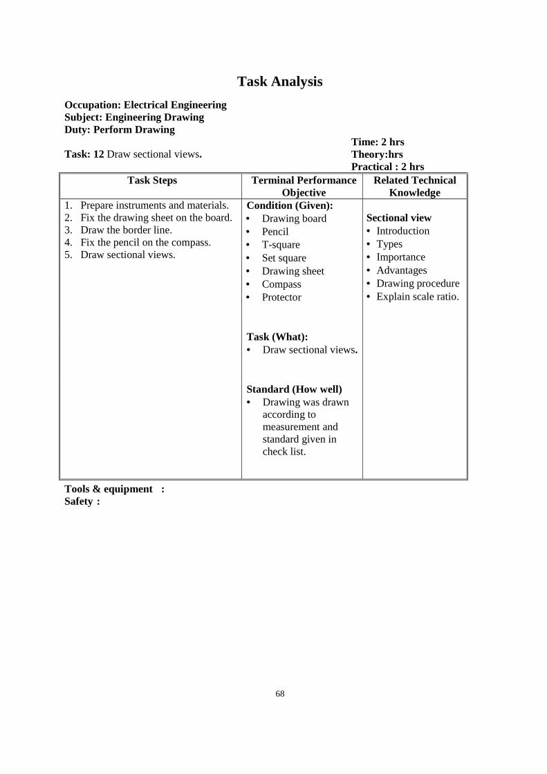
68
Task Analysis
Occupation: Electrical Engineering Subject: Engineering Drawing Duty: Perform Drawing Task: 12 Draw sectional views.
Time: 2 hrs Theory:hrs Practical : 2 hrs
Task Steps Terminal Performance Objective
Related Technical Knowledge
1. Prepare instruments and materials. 2. Fix the drawing sheet on the board. 3. Draw the border line. 4. Fix the pencil on the compass. 5. Draw sectional views.
Condition (Given): • Drawing board • Pencil • T-square • Set square • Drawing sheet • Compass • Protector
Sectional view • Introduction • Types • Importance • Advantages • Drawing procedure • Explain scale ratio.
Task (What): • Draw sectional views.
Standard (How well) • Drawing was drawn
according to measurement and standard given in check list.
Tools & equipment : Safety :
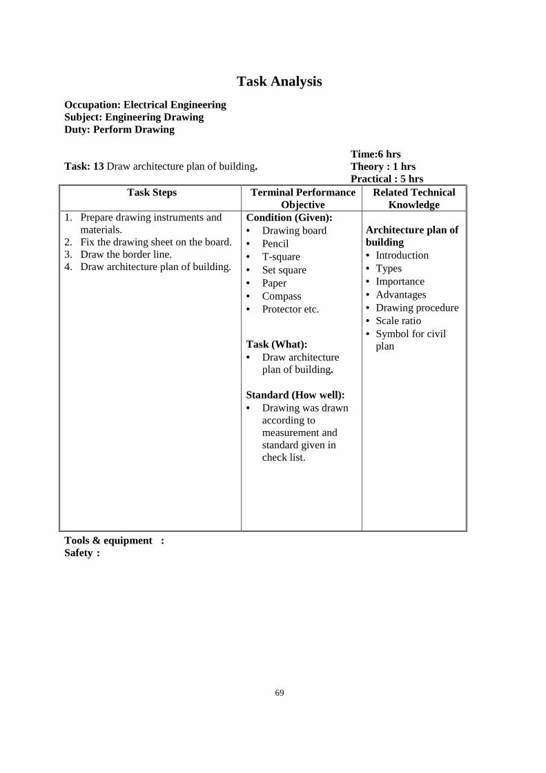
69
Task Analysis
Occupation: Electrical Engineering Subject: Engineering Drawing Duty: Perform Drawing Task: 13 Draw architecture plan of building.
Time:6 hrs Theory : 1 hrs Practical : 5 hrs
Task Steps Terminal Performance Objective
Related Technical Knowledge
1. Prepare drawing instruments and materials.
2. Fix the drawing sheet on the board. 3. Draw the border line. 4. Draw architecture plan of building.
Condition (Given): • Drawing board • Pencil • T-square • Set square • Paper • Compass • Protector etc.
Architecture plan of building • Introduction • Types • Importance • Advantages • Drawing procedure • Scale ratio • Symbol for civil
plan
Task (What): • Draw architecture
plan of building.
Standard (How well): • Drawing was drawn
according to measurement and standard given in check list.
Tools & equipment : Safety :
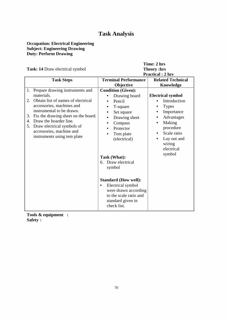
70
Task Analysis
Occupation: Electrical Engineering Subject: Engineering Drawing Duty: Perform Drawing Task: 14 Draw electrical symbol
Time: 2 hrs Theory :hrs Practical : 2 hrs
Task Steps Terminal Performance Objective
Related Technical Knowledge
1. Prepare drawing instruments and materials.
2. Obtain list of names of electrical accessories, machines and instrumental to be drawn.
3. Fix the drawing sheet on the board. 4. Draw the boarder line. 5. Draw electrical symbols of
accessories, machine and instruments using tem plate
Condition (Given): • Drawing board • Pencil • T-square • Set square • Drawing sheet • Compass • Protector • Tem plate
(electrical)
Electrical symbol
• Introduction • Types • Importance • Advantages • Making
procedure • Scale ratio • Lay out and
wiring electrical symbol
Task (What): 6. Draw electrical
symbol
Standard (How well): • Electrical symbol
were drawn according to the scale ratio and standard given in check list.
Tools & equipment : Safety :
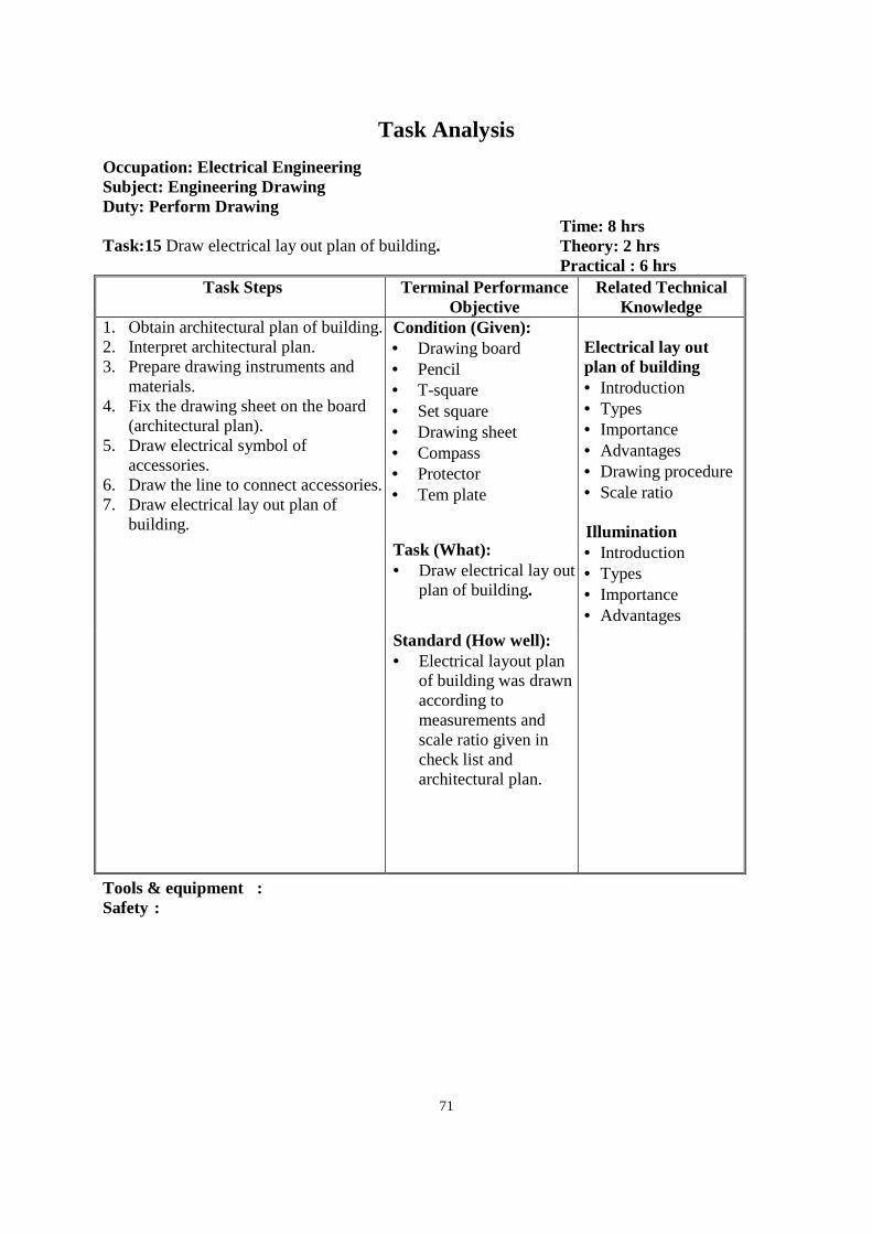
71
Task Analysis
Occupation: Electrical Engineering Subject: Engineering Drawing Duty: Perform Drawing Task:15 Draw electrical lay out plan of building.
Time: 8 hrs Theory: 2 hrs Practical : 6 hrs
Task Steps Terminal Performance Objective
Related Technical Knowledge
1. Obtain architectural plan of building. 2. Interpret architectural plan. 3. Prepare drawing instruments and
materials. 4. Fix the drawing sheet on the board
(architectural plan). 5. Draw electrical symbol of
accessories. 6. Draw the line to connect accessories. 7. Draw electrical lay out plan of
building.
Condition (Given): • Drawing board • Pencil • T-square • Set square • Drawing sheet • Compass • Protector • Tem plate
Electrical lay out plan of building • Introduction • Types • Importance • Advantages • Drawing procedure • Scale ratio Illumination • Introduction • Types • Importance • Advantages
Task (What): • Draw electrical lay out
plan of building.
Standard (How well): • Electrical layout plan
of building was drawn according to measurements and scale ratio given in check list and architectural plan.
Tools & equipment : Safety :

72
Task Analysis
Occupation: Electrical Engineering Subject: Engineering Drawing Duty: Perform Drawing Task: 16 Draw wiring and current path diagram
Time: 10 hrs Theory: 2 hrs Practical : 8 hrs
Task Steps Terminal Performance Objective
Related Technical Knowledge
1. Prepare drawing instruments and materials.
2. Fixed the drawing sheet on the board.
3. Draw the border line. 4. Fix the pencil on the compass. 5. Draw wiring and current path
diagram
Condition (Given): • Drawing board • Pencil • T-square • Set square • Drawing sheet • Compass • Protector
Wiring and current path diagram • Introduction • Types • Importance • Advantages • Drawing procedure • Scale ratio
Task (What): • Draw wiring and
current path diagram
Standard (How well): • Electrical current path
diagram was drawn according measurement and standard given in check list.
Tools & equipment : Safety :
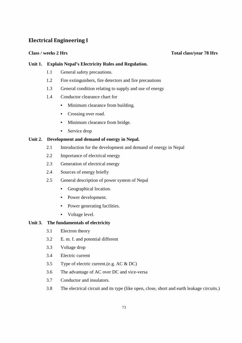
73
Electrical Engineering I
Class / weeks 2 Hrs Total class/year 78 Hrs Unit 1. Explain Nepal’s Electricity Rules and Regulation.
1.1 General safety precautions.
1.2 Fire extinguishers, fire detectors and fire precautions
1.3 General condition relating to supply and use of energy
1.4 Conductor clearance chart for
• Minimum clearance from building.
• Crossing over road.
• Minimum clearance from bridge.
• Service drop
Unit 2. Development and demand of energy in Nepal.
2.1 Introduction for the development and demand of energy in Nepal
2.2 Importance of electrical energy
2.3 Generation of electrical energy
2.4 Sources of energy briefly
2.5 General description of power system of Nepal
• Geographical location.
• Power development.
• Power generating facilities.
• Voltage level.
Unit 3. The fundamentals of electricity
3.1 Electron theory
3.2 E. m. f. and potential different
3.3 Voltage drop
3.4 Electric current
3.5 Type of electric current.(e.g. AC & DC)
3.6 The advantage of AC over DC and vice-versa
3.7 Conductor and insulators.
3.8 The electrical circuit and its type (like open, close, short and earth leakage circuits.)
74
Unit 4. Fundamental electrical parameters
4.1 Definition of Resistance, ohmic resistance, resistor and variable resistor, rheostat.
4.2 Define specific resistance of a conductor.
4.3 Describe the law of electrical resistance
• Length
• Cross section area
• Materials
• Temperature
4.4 Inductance and inductive reactance.
4.5 Capacitance & capacitive reactance.
4.6 The law of electrical resistance.
4.7 Impact of above parameters(R,L&C) in electrical circuit
4.8 Describe the temperature coefficient of resistance.
Unit 5. Explain the fundamental laws of electricity
5.1 Ohm’s law and its defining question
5.2 The application of ohm’s law in electrical circuit.
5.3 Kirchoff’s current law and its defining equation.
5.4 The application of Krichoff’s current law in electrical circuit.
5.5 Kirchoff’s voltage law and its defining equation.
5.6 The application of Krichoff’s voltage law in electrical circuit.
5.7 The series combination of resistance, its characteristics and application.
5.8 The parallel combination of resistance, It’s characteristics and application.
5.9 The mixed (series – parallel) combination of resistance, its characteristics and
application.
Unit 6. Explain effect of electrical circuit
6.1 The heating effect of electrical current.
6.2 Joule’s law of heat and thermal efficiency.
6.3 The practical application of heating effect.
6.4 The chemical effect of electrical current.
6.5 The practical application of chemical effect.
6.6 The magnetic effect of electrical current.
6.7 The practical application of magnetic effect.
75
Unit 7. Cell and battery
7.1 The characteristic of cell.
7.2 Definition of anode and cathode.
7.3 Type of cell like primary and secondary cell.
7.4 The construction and working principle including chemical reaction of dry cell.
7.5 Construction and working principle including chemical reaction of secondary cell
(or lead acid battery).
7.6 The total resistance, total e. m. f. and load current when the cell are
• Series combination
• Parallel combination.
• Mixed combination.
7.7 The preparation of an electrolyte.
7.8 Charging and discharging of a battery.
7.9 Explain the internal resistance of lead acid battery.
Unit 8. Fundamental principle of magnetism
8.1 Definition of magnet and its types.
8.2 Definition of pole of magnet.
8.3 The law of magnetic force.
8.4 Definition of magnetic field.
8.5 Definition of magnetic flux and magnetic flux density.
8.6 Description of magnetic materials like diamagnetic, paramagnetic and
ferromagnetic materials.
8.7 The methods of making magnet.
Unit 9. The fundamental principle of electromagnetism
9.1 Define electro magnetism.
9.2 Describe the principle of electromagnetic induction.
9.3 Define flux linkages.
9.4 Define Faraday’s law of electromagnetic induction.
9.5 Describe advantage of electromagnet.
9.6 Describe Lenz’s law to find the direction of induce e. m. f.
9.7 Describe Fleming right hand rule to find the direction of induce e. m. f. and current.
76
Unit 10. AC three phase system
10.1 The reasons for use of a 3 phase system
10.2 Phase sequence.
10.3 The star or Y connection.
10.4 Voltage and currents in balance in star connection.
10.5 Delta or mesh connection.
10.6 Voltage and currents in balance in mesh or delta connection.
10.7 Advantage of star connection.
10.8 Advantage of delta connection.
Unit 11. Magnetism and electromagnetism
11.1 Definition of magnetism
11.2 Compare between natural magnet and electromagnet
11.3 Importance of magnet in electrical machines
11.4 Properties of magnet
11.5 Current carrying conductor in magnetic field
77
Workshop Technology
Year 1st Class / weeks 2 Hrs Total class/year 78 Hrs Safety rules and regulation
1.1 Definition of safety. 1.2 Accident
1.2.1 Definition of accident 1.2.2 Causes of accident
1.3 Types of safety 1.3.1 Personal safety.
1.3.1.1 Definition of personal safety 1.3.2 Work shop safety.
1.3.2.1 Definition of workshop safety 1.3.3 Hand Tools safety.
1.3.3.1 Definition of hand tools safety 1.3.4 Machineand equipment safety
1.3.4.1 Definition of machine and equipment safety 1.3.5 Electrical Safety.
1.3.5.1 Definition of electrical sock 1.3.5.2 Definition of electrical safety
1.4 Safety sign. 1.4.1 Definition of safety sign. 1.4.2 Symbol of safety sign
1.5 Safety precaution. 1.6 Elementary first aid after electrical shock
1.6.1 Definition of first aid 1.6.2 Definition of electrical shock
1.7 Effect of electric shock on human body 1.8 Fire hazards and fire lighting equipment
1.8.1 Definition of fire hazards 1.8.2 Definition of fire lighting equipment
2 Mechanical tools & equipments 2.1 Bench vice
2.1.1 Definition 2.1.2 Size 2.1.3 Safety precaution while handling
2.2 File 2.2.1 Definition 2.2.2 Type 2.2.3 Safety precaution while filling or / Handling 2.2.4 Application of filling
2.3 Measure 2.3.1 Definition 2.3.2 Types Measuring tools 2.3.3 Application
2.4 Marking 2.4.1 Definition
78
2.4.2 Types of marking tools 2.4.3 Applications 2.4.4 Safety precaution while marking
2.5 Chisels 2.5.1 Definition 2.5.2 Types 2.5.3 Application 2.5.4 Safety precaution while chiseling
2.6 Sawing 2.6.1 Definition 2.6.2 Types of saw 2.6.3 Size of hack saw blade 2.6.4 Parts of saw 2.6.5 Application 2.6.6 Safety precaution while sawing
2.7 Drill Machine 2.7.1 Definition 2.7.2 Types 2.7.3 Parts of drill machine 2.7.4 Safety precaution while handling various drill machine 2.7.5 Application 2.7.6 Operation and process drilling 2.7.7 Calculate the speed of drilling 2.7.8 Size of drill bit 2.7.9 Type of drill bit 2.7.10 Safety precaution while handling drill machine
2.8 Joint (Sheet Metal) 2.8.1 Definition 2.8.2 Types 2.8.3 Application 2.8.4 Rivet
2.8.4.1 Definition 2.8.4.2 Type of rivet 2.8.4.3 Safety precaution while handling riveting tools
3 Electrical hand tools and Equipments 3.1 Definition of electrical hand tools and equipment
3.1.1 Screw driver 3.1.1.1 Phillips (Plus) 3.1.1.2 Standard (Minus) 3.1.1.3 Application
3.1.2 Pliers 3.1.2.1 Combination pliers 3.1.2.2 Side cutter 3.1.2.3 Round nose pliers 3.1.2.4 Half round nose pliers 3.1.2.5 Application
3.1.3 Wire stripper 3.1.3.1 Application
79
3.1.4 Phase Tester 3.1.5 Hammer
3.1.5.1 Ball pin hammer 3.1.5.2 Steel Hammer 3.1.5.3 Mallets 3.1.5.4 Applications
3.1.6 Standard wire gauge 3.1.6.1 Definition 3.1.6.2 Application
3.1.7Multimeter 3.1.7.2 Definition 3.1.7.3 Uses
3.1.7.3 Types 3.1.7.4 Safety 4 Properties of electrical and magnetic materials
4.1 Electrical materials 4.1.7 Definition 4.1.8 Types
4.1.8.2 Copper 4.1.8.2.1 Definition 4.1.8.2.2 Working properties 4.1.8.2.3 Application
4.1.8.3 Cadmium copper 4.1.8.3.1 Definition 4.1.8.3.2 Working properties 4.1.8.3.3 Application
4.1.8.4 Chromium copper 4.1.8.4.1 Definition 4.1.8.4.2 Working properties 4.1.8.4.3 Application
4.1.8.5 Tellurium copper 4.1.8.5.1 Definition 4.1.8.5.2 Working properties 4.1.8.5.3 Application
4.1.8.6 Aluminum 4.1.8.6.1 Definition 4.1.8.6.2 Working properties 4.1.8.6.3 Application
4.1.9 Conductor 4.1.9.2 Definition of conducting materials 4.1.9.3 Properties of conductor 4.1.9.4 Classification of conducting materials
4.1.10 Insulator 4.1.10.2 Definition ofinsulator 4.1.10.3 Properties of insulator 4.1.10.4 Classification of Insulation
4.1.11 Wire 4.1.11.2 Definition of wire
80
4.1.11.3 Types of wire 4.1.11.4 Application of wire
4.1.12 Cable 4.1.12.2 Definition of cable 4.1.12.3 Parts of cable 4.1.12.4 Types of cable 4.1.12.5 Application of cable 4.1.12.6 List out the necessity and advantage of cable 4.1.12.7 Voltage grade of cable
5 Electrical accessories and its types 5.1 Definition of electrical accessories 5.2 Types of electrical accessories
5.2.7 Major 5.2.7.2 Definition 5.2.7.3 Application
5.2.8 Auxiliaries 5.2.8.2 Definition 5.2.8.3 Application
5.3 Classification of general electrical device 5.3.7 Conducting device
5.3.7.2 Definition 5.3.7.3 Types of conducting device
5.3.7.3.1 Wire 5.3.7.3.2 Cable 5.3.7.3.3 Bare conductor 5.3.7.3.4 Flexible conductor 5.3.7.3.5 Solid conductor 5.3.7.3.6 Standard conductor 5.3.7.4 Application
5.3.8 Controlling device 5.3.8.2 Definition 5.3.8.3 Types of controlling device
5.3.8.3.1 One way switch 5.3.8.3.2 Two way switch 5.3.8.3.3 Push bottom Switch 5.3.8.3.4 Intermediate Switch 5.3.8.3.5 Tumble Switch 5.3.8.3.6 Rotary Switch 5.3.8.3.7 Toggle Switch 5.3.8.3.8 SlideSwitch 5.3.8.3.9 Pull Switch 5.3.8.4 Application
5.3.9 Safety Device (Protective device) 5.3.9.2 Definition 5.3.9.3 Types of safety device
5.3.9.3.1 Kit Kat fuse 5.3.9.3.2 MCB 5.3.9.3.3 MCCB
81
5.3.9.3.4 HRC 5.3.9.3.5 Micro fuse 5.3.9.3.6 Cartridge fuse 5.3.9.3.7 Glass fuse (for electronics devices)
5.3.9.4 Application 5.3.10 Consuming device
5.3.10.2 Definition 5.3.10.3 Types of consuming device
5.3.10.3.1 Bulb 5.3.10.3.2 Fluorescent light 5.3.10.3.3 Fan 5.3.10.3.4 Motor 5.3.10.3.5 Heater, iron, oven 5.3.10.3.6 Rice cooker
5.3.10.4 Application 6 Earthing
6.1 Definitionof earthing 6.2 Types of earthing
6.2.7 Plate earthing 6.2.8 Pipeearthing
6.3 Method of Earting 6.3.7 Equipment earthing 6.3.8 Systemearthing
6.4 Importance of earthing 6.5 Process of earthing 6.6 Resistance of earth electrode
6.6.7 Definition of earth electrode 6.6.8 Definition of Earth resistance
6.7 Application of earthing
82
Computer I
` Task: 1. Perform in DOS (5+1=6 hrs)
2. Perform in MS Windows System (5+1=6 hrs)
3. Perform typing work. (5+1=6 hrs)
4. Perform in Word Processing Program. (5+1=6 hrs)
5. Perform in Spreadsheet Program. (5+1=6 hrs)
6. Perform in Multimedia (Media player in PC) (2+1=3 hrs)
7. Perform e-mail, internet operation. (3+1=4 hrs)
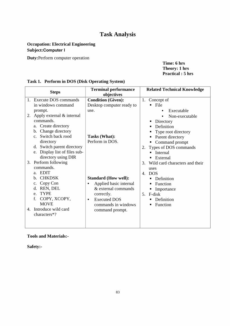
83
Task Analysis
Occupation: Electrical Engineering Subject:Computer I
Duty:Perform computer operation Time: 6 hrs Theory: 1 hrs Practical : 5 hrs
Task 1. Perform in DOS (Disk Operating System)
Steps Terminal performance objectives
Related Technical Knowledge
1. Execute DOS commands in windows command prompt.
2. Apply external & internal commands. a. Create directory b. Change directory c. Switch back rood
directory d. Switch parent directory e. Display list of files sub-
directory using DIR 3. Perform following
commands. a. EDIT b. CHKDSK c. Copy Con d. REN, DEL e. TYPE f. COPY, XCOPY,
MOVE 4. Introduce wild card
characters*?
Condition (Given): Desktop computer ready to use. Tasks (What): Perform in DOS. Standard (How well): • Applied basic internal
& external commands correctly.
• Executed DOS commands in windows command prompt.
1. Concept of File
• Executable • Non-executable
Directory Definition Type root directory Parent directory Command prompt
2. Types of DOS commands Internal External
3. Wild card characters and their uses
4. DOS Definition Function Importance
5. F-disk Definition Function
Tools and Materials:- Safety:-
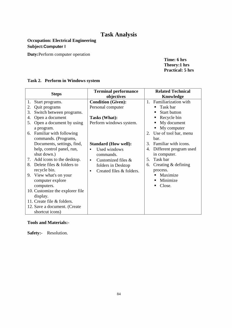
84
Task Analysis Occupation: Electrical Engineering Subject:Computer I
Duty:Perform computer operation Time: 6 hrs Theory:1 hrs Practical: 5 hrs
Task 2. Perform in Windows system
Steps Terminal performance objectives
Related Technical Knowledge
1. Start programs. 2. Quit programs 3. Switch between programs. 4. Open a document 5. Open a document by using
a program. 6. Familiar with following
commands. (Programs, Documents, settings, find, help, control panel, run, shut down.)
7. Add icons to the desktop. 8. Delete files & folders to
recycle bin. 9. View what's on your
computer explore computers.
10. Customize the explorer file display.
11. Create file & folders. 12. Save a document. (Create
shortcut icons)
Condition (Given): Personal computer Tasks (What): Perform windows system. Standard (How well): • Used windows
commands. • Customized files &
folders in Desktop • Created files & folders.
1. Familiarization with Task bar Start button Recycle bin My document My computer
2. Use of tool bar, menu bar.
3. Familiar with icons. 4. Different program used
in computer. 5. Task bar 6. Creating & defining
process. Maximize Minimize Close.
Tools and Materials:- Safety:- Resolution.
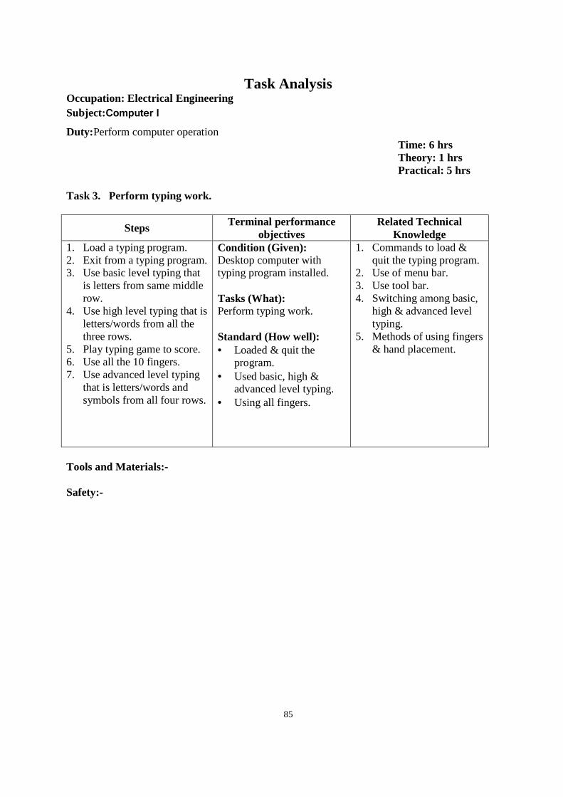
85
Task Analysis Occupation: Electrical Engineering Subject:Computer I
Duty:Perform computer operation Time: 6 hrs Theory: 1 hrs Practical: 5 hrs
Task 3. Perform typing work.
Steps Terminal performance objectives
Related Technical Knowledge
1. Load a typing program. 2. Exit from a typing program. 3. Use basic level typing that
is letters from same middle row.
4. Use high level typing that is letters/words from all the three rows.
5. Play typing game to score. 6. Use all the 10 fingers. 7. Use advanced level typing
that is letters/words and symbols from all four rows.
Condition (Given): Desktop computer with typing program installed. Tasks (What): Perform typing work. Standard (How well): • Loaded & quit the
program. • Used basic, high &
advanced level typing. • Using all fingers.
1. Commands to load & quit the typing program.
2. Use of menu bar. 3. Use tool bar. 4. Switching among basic,
high & advanced level typing.
5. Methods of using fingers & hand placement.
Tools and Materials:- Safety:-
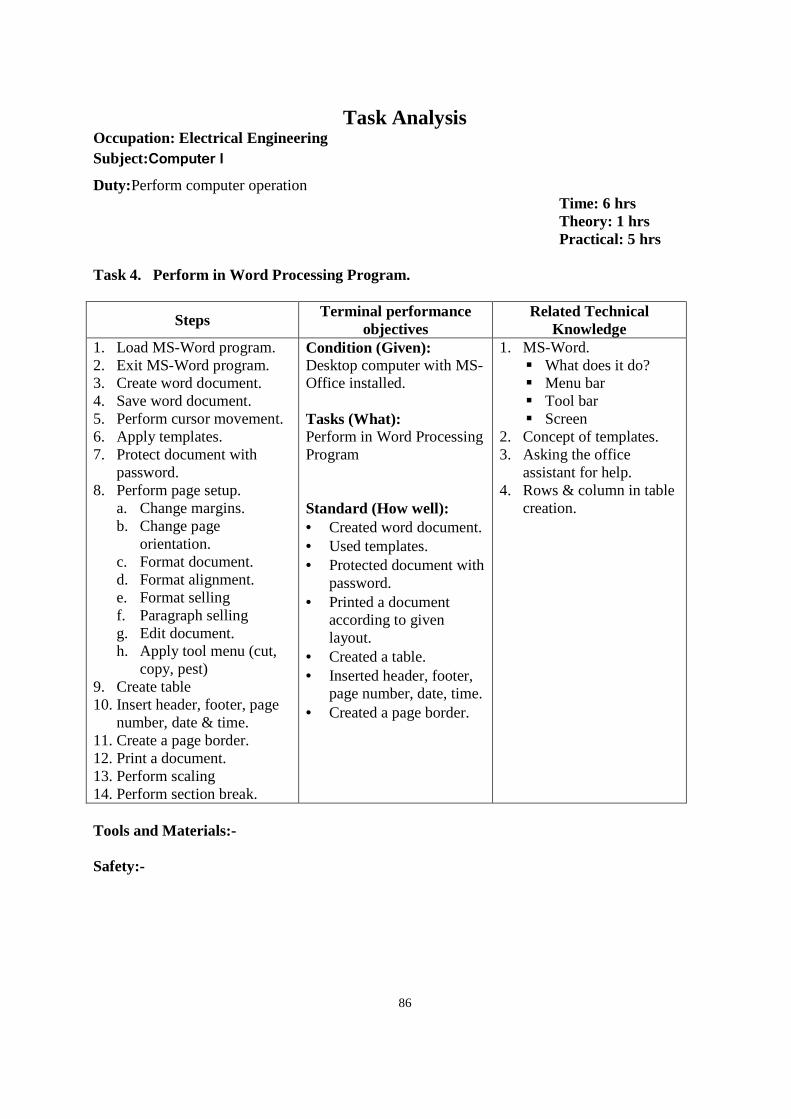
86
Task Analysis Occupation: Electrical Engineering Subject:Computer I
Duty:Perform computer operation Time: 6 hrs Theory: 1 hrs Practical: 5 hrs
Task 4. Perform in Word Processing Program.
Steps Terminal performance objectives
Related Technical Knowledge
1. Load MS-Word program. 2. Exit MS-Word program. 3. Create word document. 4. Save word document. 5. Perform cursor movement. 6. Apply templates. 7. Protect document with
password. 8. Perform page setup.
a. Change margins. b. Change page
orientation. c. Format document. d. Format alignment. e. Format selling f. Paragraph selling g. Edit document. h. Apply tool menu (cut,
copy, pest) 9. Create table 10. Insert header, footer, page
number, date & time. 11. Create a page border. 12. Print a document. 13. Perform scaling 14. Perform section break.
Condition (Given): Desktop computer with MS-Office installed. Tasks (What): Perform in Word Processing Program Standard (How well): • Created word document. • Used templates. • Protected document with
password. • Printed a document
according to given layout.
• Created a table. • Inserted header, footer,
page number, date, time. • Created a page border.
1. MS-Word. What does it do? Menu bar Tool bar Screen
2. Concept of templates. 3. Asking the office
assistant for help. 4. Rows & column in table
creation.
Tools and Materials:- Safety:-
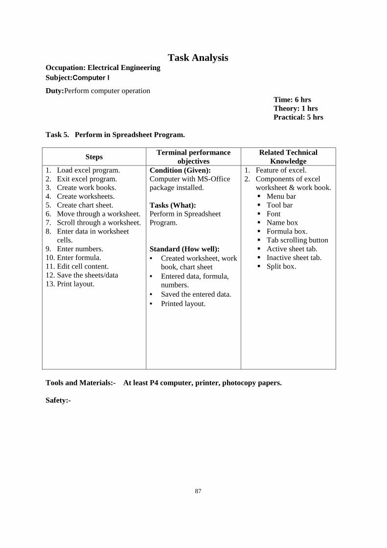
87
Task Analysis Occupation: Electrical Engineering Subject:Computer I
Duty:Perform computer operation Time: 6 hrs Theory: 1 hrs Practical: 5 hrs
Task 5. Perform in Spreadsheet Program.
Steps Terminal performance objectives
Related Technical Knowledge
1. Load excel program. 2. Exit excel program. 3. Create work books. 4. Create worksheets. 5. Create chart sheet. 6. Move through a worksheet. 7. Scroll through a worksheet. 8. Enter data in worksheet
cells. 9. Enter numbers. 10. Enter formula. 11. Edit cell content. 12. Save the sheets/data 13. Print layout.
Condition (Given): Computer with MS-Office package installed. Tasks (What): Perform in Spreadsheet Program. Standard (How well): • Created worksheet, work
book, chart sheet • Entered data, formula,
numbers. • Saved the entered data. • Printed layout.
1. Feature of excel. 2. Components of excel
worksheet & work book. Menu bar Tool bar Font Name box Formula box. Tab scrolling button Active sheet tab. Inactive sheet tab. Split box.
Tools and Materials:- At least P4 computer, printer, photocopy papers. Safety:-
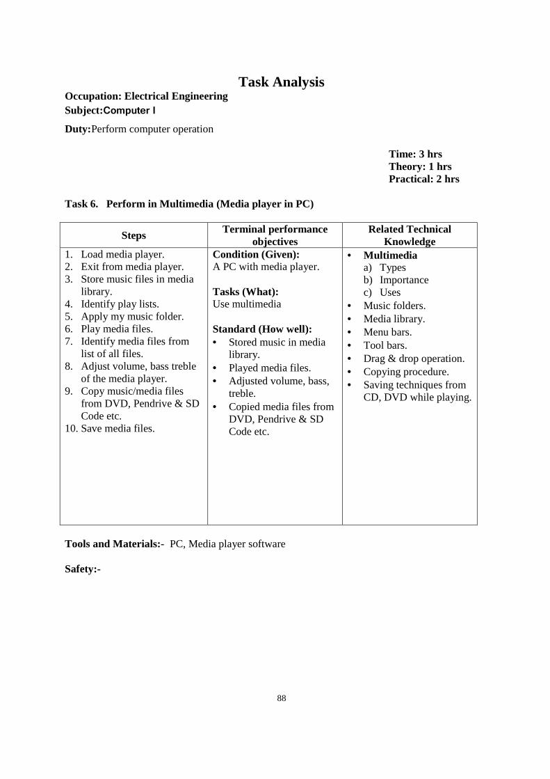
88
Task Analysis Occupation: Electrical Engineering Subject:Computer I
Duty:Perform computer operation
Time: 3 hrs Theory: 1 hrs Practical: 2 hrs
Task 6. Perform in Multimedia (Media player in PC)
Steps Terminal performance objectives
Related Technical Knowledge
1. Load media player. 2. Exit from media player. 3. Store music files in media
library. 4. Identify play lists. 5. Apply my music folder. 6. Play media files. 7. Identify media files from
list of all files. 8. Adjust volume, bass treble
of the media player. 9. Copy music/media files
from DVD, Pendrive & SD Code etc.
10. Save media files.
Condition (Given): A PC with media player. Tasks (What): Use multimedia Standard (How well): • Stored music in media
library. • Played media files. • Adjusted volume, bass,
treble. • Copied media files from
DVD, Pendrive & SD Code etc.
• Multimedia a) Types b) Importance c) Uses
• Music folders. • Media library. • Menu bars. • Tool bars. • Drag & drop operation. • Copying procedure. • Saving techniques from
CD, DVD while playing.
Tools and Materials:- PC, Media player software Safety:-
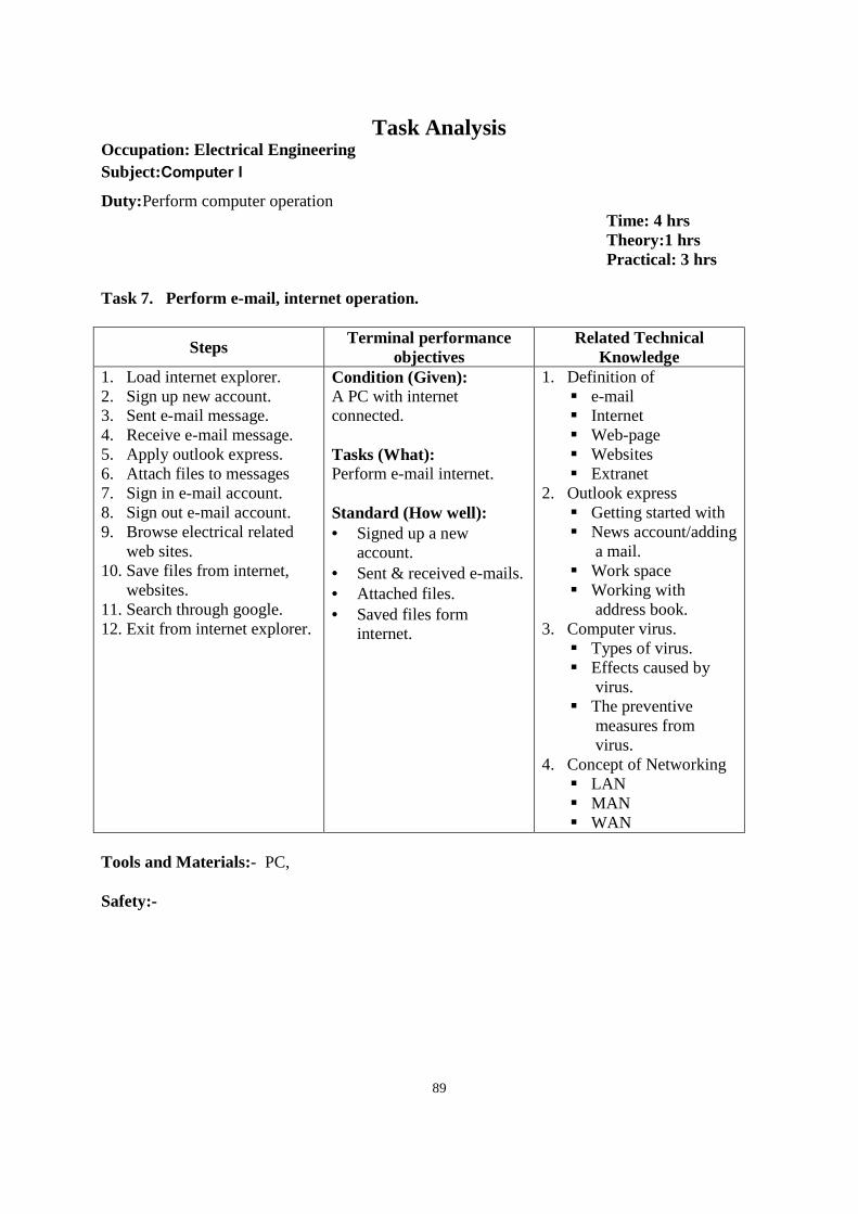
89
Task Analysis Occupation: Electrical Engineering Subject:Computer I
Duty:Perform computer operation Time: 4 hrs Theory:1 hrs Practical: 3 hrs
Task 7. Perform e-mail, internet operation.
Steps Terminal performance objectives
Related Technical Knowledge
1. Load internet explorer. 2. Sign up new account. 3. Sent e-mail message. 4. Receive e-mail message. 5. Apply outlook express. 6. Attach files to messages 7. Sign in e-mail account. 8. Sign out e-mail account. 9. Browse electrical related
web sites. 10. Save files from internet,
websites. 11. Search through google. 12. Exit from internet explorer.
Condition (Given): A PC with internet connected. Tasks (What): Perform e-mail internet. Standard (How well): • Signed up a new
account. • Sent & received e-mails. • Attached files. • Saved files form
internet.
1. Definition of e-mail Internet Web-page Websites Extranet
2. Outlook express Getting started with News account/adding
a mail. Work space Working with
address book. 3. Computer virus.
Types of virus. Effects caused by
virus. The preventive
measures from virus.
4. Concept of Networking LAN MAN WAN
Tools and Materials:- PC, Safety:-
90
Second Year
Subjects 1. Industrial Electrical Installation 2. Motor Installation and Control System 3. Repair & Maintenance of Winding Machine 4. Overhead and Underground Line Installation 5. Basic Electronics 6. Engineering Drawing II- AutoCAD 7. Electrical Engineering II 8. Workshop Technology II 9. Electrical Machine 10. Applied Math II 11. Entrepreneurship Development 12. On–The Job Training (OJT)
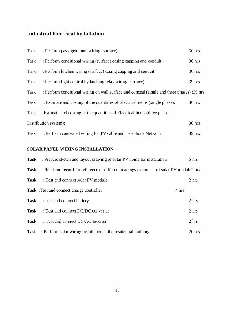
91
Industrial Electrical Installation
Task : Perform passage/tunnel wiring (surface): 30 hrs
Task : Perform conditional wiring (surface) casing capping and conduit : 30 hrs
Task : Perform kitchen wiring (surface) casing capping and conduit : 30 hrs
Task : Perform light control by latching relay wiring (surface) : 39 hrs
Task : Perform conditional wiring on wall surface and conceal (single and three phases) :39 hrs
Task : Estimate and costing of the quantities of Electrical items (single phase): 36 hrs
Task :Estimate and costing of the quantities of Electrical items (three phase
Distribution system): 30 hrs
Task : Perform concealed wiring for TV cable and Telephone Network: 39 hrs
SOLAR PANEL WIRING INSTALLATION Task : Prepare sketch and layout drawing of solar PV home for installation 5 hrs
Task : Read and record for reference of different readings parameter of solar PV module2 hrs
Task : Test and connect solar PV module 2 hrs
Task :Test and connect charge controller 4 hrs
Task :Test and connect battery 2 hrs
Task : Test and connect DC/DC converter 2 hrs
Task : Test and connect DC/AC Inverter 2 hrs
Task : Perform solar wiring installation at the residential building. 20 hrs
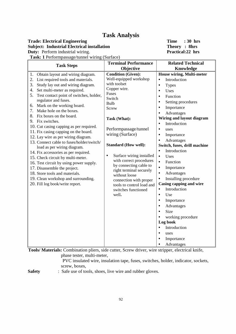
92
Task Analysis Trade: Electrical Engineering Time : 30 hrs Subject: Industrial Electrical installation Theory : 8hrs Duty: Perform industrial wiring. Practical:22 hrs Task: 1 Performpassage/tunnel wiring (Surface)
Task Steps Terminal Performance Objective
Related Technical Knowledge
1. Obtain layout and wiring diagram. 2. List required tools and materials. 3. Study lay out and wiring diagram. 4. Set multi-meter as required. 5. Test contact point of switches, holder,
regulator and fuses. 6. Mark on the working board. 7. Make hole on the boxes. 8. Fix boxes on the board. 9. Fix switches. 10. Cut casing capping as per required. 11. Fix casing capping on the board. 12. Lay wire as per wiring diagram. 13. Connect cable to fuses/holder/switch/
load as per wiring diagram. 14. Fix accessories as per required. 15. Check circuit by multi-meter. 16. Test circuit by using power supply. 17. Disassemble the project. 18. Store tools and materials. 19. Clean workshop and surrounding. 20. Fill log book/write report.
Condition (Given): Well-equipped workshop with toolset Copper wire. Fuses Switch Bulb Screw Task (What): Performpassage/tunnel wiring (Surface) Standard (How well): • Surface wiring installed
with correct procedures by connecting cable to right terminal securely without loose connection with proper tools to control load and switches functioned well.
House wiring, Multi-meter • Introduction • Types • Uses • Function • Setting procedures • Importance • Advantages Wiring and layout diagram • Introduction • uses • Importance • Advantages Switch, fuses, drill machine • Introduction • Uses • Function • Importance • Advantages • Installing procedure Casing capping and wire • Introduction • Use • Importance • Advantages • Size • working procedure Log book • Introduction • uses • Importance • Advantages
Tools/ Materials: Combination pliers, side cutter, Screw driver, wire stripper, electrical knife, phase tester, multi-meter, PVC insulated wire, insulation tape, fuses, switches, holder, indicator, sockets,
screw, boxes, Safety : Safe use of tools, shoes, live wire and rubber gloves.
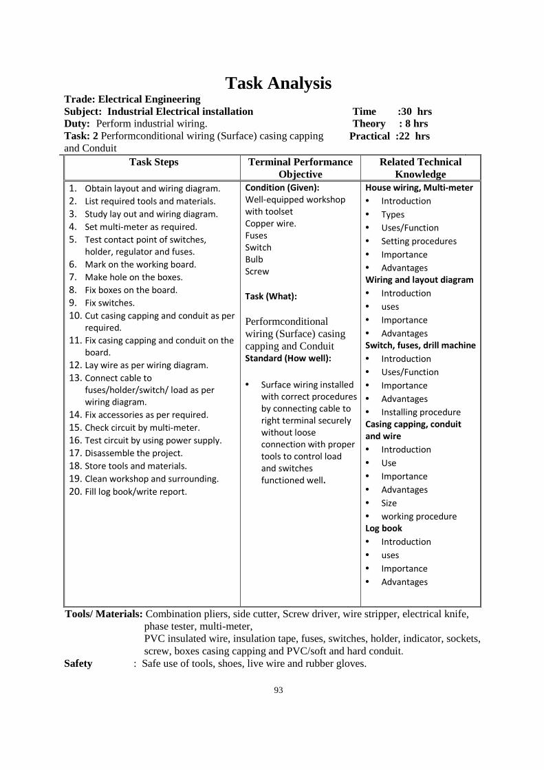
93
Task Analysis Trade: Electrical Engineering Subject: Industrial Electrical installation Time :30 hrs Duty: Perform industrial wiring. Theory : 8 hrs Task: 2 Performconditional wiring (Surface) casing capping and Conduit
Practical :22 hrs
Task Steps Terminal Performance Objective
Related Technical Knowledge
1. Obtain layout and wiring diagram.
2. List required tools and materials.
3. Study lay out and wiring diagram.
4. Set multi-meter as required.
5. Test contact point of switches,
holder, regulator and fuses.
6. Mark on the working board.
7. Make hole on the boxes.
8. Fix boxes on the board.
9. Fix switches.
10. Cut casing capping and conduit as per
required.
11. Fix casing capping and conduit on the
board.
12. Lay wire as per wiring diagram.
13. Connect cable to
fuses/holder/switch/ load as per
wiring diagram.
14. Fix accessories as per required.
15. Check circuit by multi-meter.
16. Test circuit by using power supply.
17. Disassemble the project.
18. Store tools and materials.
19. Clean workshop and surrounding.
20. Fill log book/write report.
Condition (Given):
Well-equipped workshop
with toolset
Copper wire.
Fuses
Switch
Bulb
Screw
Task (What):
Performconditional wiring (Surface) casing capping and Conduit Standard (How well):
• Surface wiring installed
with correct procedures
by connecting cable to
right terminal securely
without loose
connection with proper
tools to control load
and switches
functioned well.
House wiring, Multi-meter
• Introduction
• Types
• Uses/Function
• Setting procedures
• Importance
• Advantages Wiring and layout diagram
• Introduction
• uses
• Importance
• Advantages Switch, fuses, drill machine
• Introduction
• Uses/Function
• Importance
• Advantages
• Installing procedure
Casing capping, conduit
and wire
• Introduction
• Use
• Importance
• Advantages
• Size
• working procedure Log book
• Introduction
• uses
• Importance
• Advantages
Tools/ Materials: Combination pliers, side cutter, Screw driver, wire stripper, electrical knife, phase tester, multi-meter, PVC insulated wire, insulation tape, fuses, switches, holder, indicator, sockets, screw, boxes casing capping and PVC/soft and hard conduit.
Safety : Safe use of tools, shoes, live wire and rubber gloves.
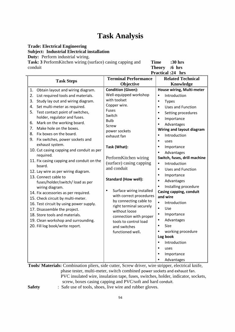
94
Task Analysis
Trade: Electrical Engineering Subject: Industrial Electrical installation Duty: Perform industrial wiring. Task: 3 PerformKitchen wiring (surface) casing capping and conduit
Time :30 hrs Theory :6 hrs Practical :24 hrs
Task Steps Terminal Performance Objective
Related Technical Knowledge
1. Obtain layout and wiring diagram.
2. List required tools and materials.
3. Study lay out and wiring diagram.
4. Set multi-meter as required.
5. Test contact point of switches,
holder, regulator and fuses.
6. Mark on the working board.
7. Make hole on the boxes.
8. Fix boxes on the board.
9. Fix switches, power sockets and
exhaust system.
10. Cut casing capping and conduit as per
required.
11. Fix casing capping and conduit on the
board.
12. Lay wire as per wiring diagram.
13. Connect cable to
fuses/holder/switch/ load as per
wiring diagram.
14. Fix accessories as per required.
15. Check circuit by multi-meter.
16. Test circuit by using power supply.
17. Disassemble the project.
18. Store tools and materials.
19. Clean workshop and surrounding.
20. Fill log book/write report.
Condition (Given):
Well-equipped workshop
with toolset
Copper wire.
Fuses
Switch
Bulb
Screw
power sockets
exhaust fan
Task (What):
PerformKitchen wiring (surface) casing capping and conduit
Standard (How well):
• Surface wiring installed
with correct procedures
by connecting cable to
right terminal securely
without loose
connection with proper
tools to control load
and switches
functioned well.
House wiring, Multi-meter
• Introduction
• Types
• Uses and Function
• Setting procedures
• Importance
• Advantages Wiring and layout diagram
• Introduction
• uses
• Importance
• Advantages
Switch, fuses, drill machine
• Introduction
• Uses and Function
• Importance
• Advantages
• Installing procedure Casing capping, conduit
and wire
• Introduction
• Use
• Importance
• Advantages
• Size
• working procedure Log book
• Introduction
• uses
• Importance
• Advantages
Tools/ Materials: Combination pliers, side cutter, Screw driver, wire stripper, electrical knife, phase tester, multi-meter, switch combined power sockets and exhaust fan. PVC insulated wire, insulation tape, fuses, switches, holder, indicator, sockets, screw, boxes casing capping and PVC/soft and hard conduit.
Safety : Safe use of tools, shoes, live wire and rubber gloves.
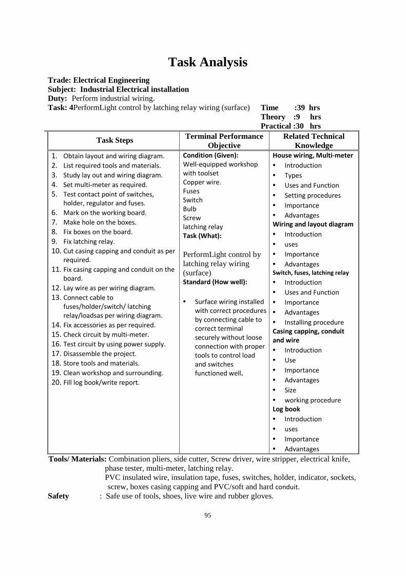
95
Task Analysis
Trade: Electrical Engineering Subject: Industrial Electrical installation Duty: Perform industrial wiring. Task: 4PerformLight control by latching relay wiring (surface)
Time :39 hrs Theory :9 hrs Practical :30 hrs
Task Steps Terminal Performance Objective
Related Technical Knowledge
1. Obtain layout and wiring diagram.
2. List required tools and materials.
3. Study lay out and wiring diagram.
4. Set multi-meter as required.
5. Test contact point of switches,
holder, regulator and fuses.
6. Mark on the working board.
7. Make hole on the boxes.
8. Fix boxes on the board.
9. Fix latching relay.
10. Cut casing capping and conduit as per
required.
11. Fix casing capping and conduit on the
board.
12. Lay wire as per wiring diagram.
13. Connect cable to
fuses/holder/switch/ latching
relay/loadsas per wiring diagram.
14. Fix accessories as per required.
15. Check circuit by multi-meter.
16. Test circuit by using power supply.
17. Disassemble the project.
18. Store tools and materials.
19. Clean workshop and surrounding.
20. Fill log book/write report.
Condition (Given):
Well-equipped workshop
with toolset
Copper wire.
Fuses
Switch
Bulb
Screw
latching relay
Task (What):
PerformLight control by latching relay wiring (surface) Standard (How well):
• Surface wiring installed
with correct procedures
by connecting cable to
correct terminal
securely without loose
connection with proper
tools to control load
and switches
functioned well.
House wiring, Multi-meter
• Introduction
• Types
• Uses and Function
• Setting procedures
• Importance
• Advantages Wiring and layout diagram
• Introduction
• uses
• Importance
• Advantages Switch, fuses, latching relay
• Introduction
• Uses and Function
• Importance
• Advantages
• Installing procedure Casing capping, conduit
and wire
• Introduction
• Use
• Importance
• Advantages
• Size
• working procedure Log book
• Introduction
• uses
• Importance
• Advantages
Tools/ Materials: Combination pliers, side cutter, Screw driver, wire stripper, electrical knife, phase tester, multi-meter, latching relay. PVC insulated wire, insulation tape, fuses, switches, holder, indicator, sockets, screw, boxes casing capping and PVC/soft and hard conduit.
Safety : Safe use of tools, shoes, live wire and rubber gloves.
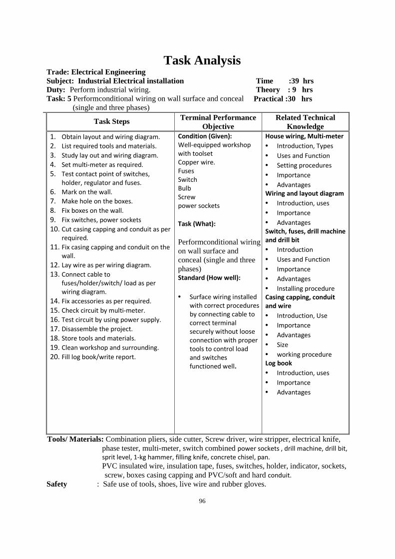
96
Task Analysis Trade: Electrical Engineering Subject: Industrial Electrical installation Time :39 hrs Duty: Perform industrial wiring. Theory : 9 hrs Task: 5 Performconditional wiring on wall surface and conceal
(single and three phases) Practical :30 hrs
Task Steps Terminal Performance Objective
Related Technical Knowledge
1. Obtain layout and wiring diagram.
2. List required tools and materials.
3. Study lay out and wiring diagram.
4. Set multi-meter as required.
5. Test contact point of switches,
holder, regulator and fuses.
6. Mark on the wall.
7. Make hole on the boxes.
8. Fix boxes on the wall.
9. Fix switches, power sockets
10. Cut casing capping and conduit as per
required.
11. Fix casing capping and conduit on the
wall.
12. Lay wire as per wiring diagram.
13. Connect cable to
fuses/holder/switch/ load as per
wiring diagram.
14. Fix accessories as per required.
15. Check circuit by multi-meter.
16. Test circuit by using power supply.
17. Disassemble the project.
18. Store tools and materials.
19. Clean workshop and surrounding.
20. Fill log book/write report.
Condition (Given):
Well-equipped workshop
with toolset
Copper wire.
Fuses
Switch
Bulb
Screw
power sockets
Task (What):
Performconditional wiring on wall surface and conceal (single and three phases) Standard (How well):
• Surface wiring installed
with correct procedures
by connecting cable to
correct terminal
securely without loose
connection with proper
tools to control load
and switches
functioned well.
House wiring, Multi-meter
• Introduction, Types
• Uses and Function
• Setting procedures
• Importance
• Advantages Wiring and layout diagram
• Introduction, uses
• Importance
• Advantages
Switch, fuses, drill machine
and drill bit
• Introduction
• Uses and Function
• Importance
• Advantages
• Installing procedure Casing capping, conduit
and wire
• Introduction, Use
• Importance
• Advantages
• Size
• working procedure
Log book
• Introduction, uses
• Importance
• Advantages
Tools/ Materials: Combination pliers, side cutter, Screw driver, wire stripper, electrical knife, phase tester, multi-meter, switch combined power sockets , drill machine, drill bit,
sprit level, 1-kg hammer, filling knife, concrete chisel, pan. PVC insulated wire, insulation tape, fuses, switches, holder, indicator, sockets, screw, boxes casing capping and PVC/soft and hard conduit.
Safety : Safe use of tools, shoes, live wire and rubber gloves.
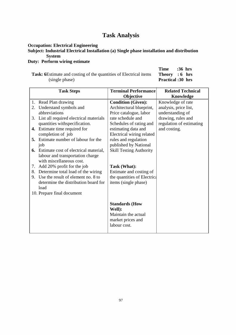
97
Task Analysis
Occupation: Electrical Engineering Subject: Industrial Electrical Installation (a) Single phase installation and distribution System Duty: Perform wiring estimate
Task: 6Estimate and costing of the quantities of Electrical items
(single phase)
Time :36 hrs Theory : 6 hrs Practical :30 hrs
Task Steps Terminal Performance Objective
Related Technical Knowledge
1. Read Plan drawing 2. Understand symbols and
abbreviations 3. List all required electrical materials
quantities withspecification. 4. Estimate time required for
completion of job 5. Estimate number of labour for the
job 6. Estimate cost of electrical material,
labour and transportation charge with miscellaneous cost.
7. Add 20% profit for the job 8. Determine total load of the wiring 9. Use the result of element no. 8 to
determine the distribution board for load
10. Prepare final document
Condition (Given): Architectural blueprint, Price catalogue, labor rate schedule and Schedules of rating and estimating data and Electrical wiring related rules and regulation published by National Skill Testing Authority Task (What): Estimate and costing of the quantities of Electrical items (single phase) Standards (How Well): Maintain the actual market prices and labour cost.
Knowledge of rate analysis, price list, understanding of drawing, rules and regulation of estimating and costing.
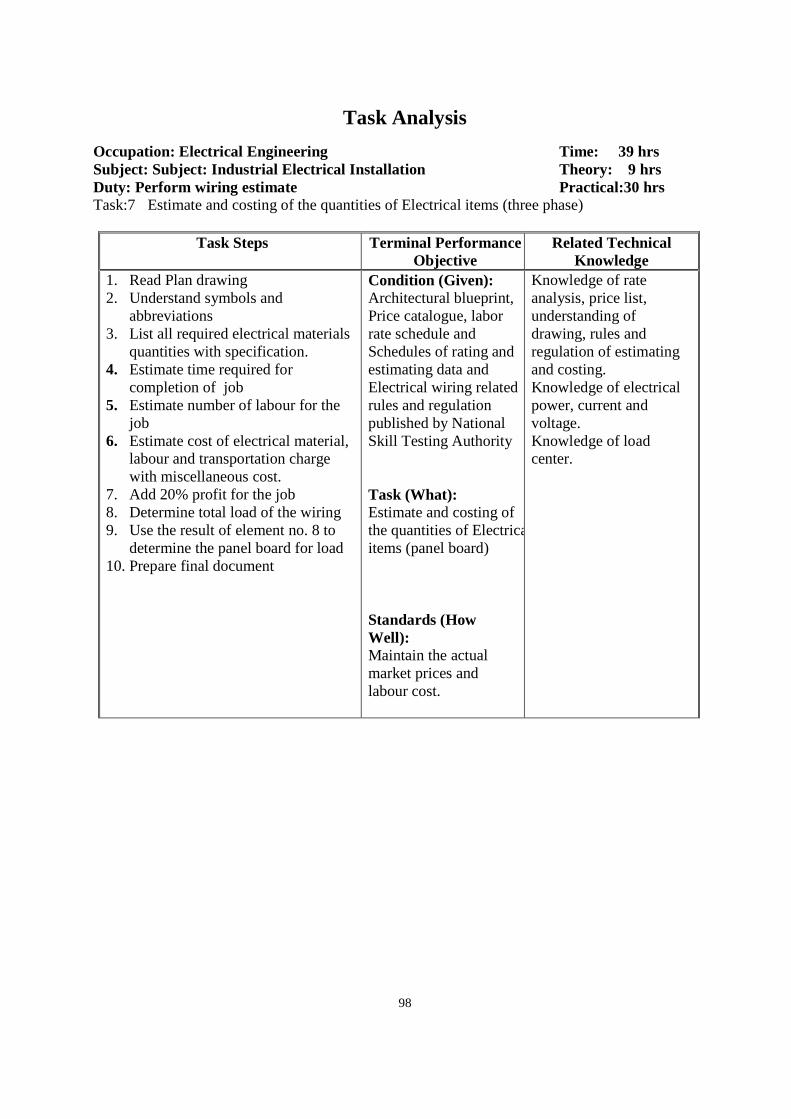
98
Task Analysis
Occupation: Electrical Engineering Time: 39 hrs Subject: Subject: Industrial Electrical Installatio n Theory: 9 hrs Duty: Perform wiring estimate Practical:30 hrs Task:7 Estimate and costing of the quantities of Electrical items (three phase)
Task Steps Terminal Performance Objective
Related Technical Knowledge
1. Read Plan drawing 2. Understand symbols and
abbreviations 3. List all required electrical materials
quantities with specification. 4. Estimate time required for
completion of job 5. Estimate number of labour for the
job 6. Estimate cost of electrical material,
labour and transportation charge with miscellaneous cost.
7. Add 20% profit for the job 8. Determine total load of the wiring 9. Use the result of element no. 8 to
determine the panel board for load 10. Prepare final document
Condition (Given): Architectural blueprint, Price catalogue, labor rate schedule and Schedules of rating and estimating data and Electrical wiring related rules and regulation published by National Skill Testing Authority Task (What): Estimate and costing of the quantities of Electrical items (panel board) Standards (How Well): Maintain the actual market prices and labour cost.
Knowledge of rate analysis, price list, understanding of drawing, rules and regulation of estimating and costing. Knowledge of electrical power, current and voltage. Knowledge of load center.
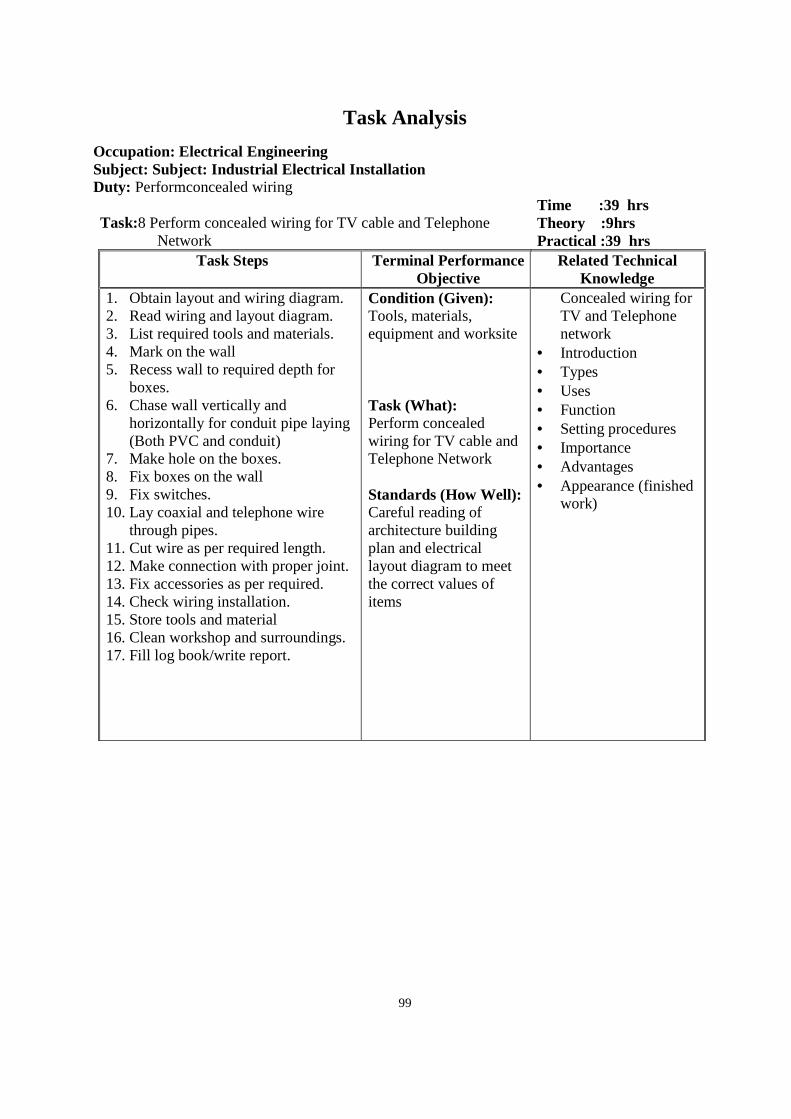
99
Task Analysis
Occupation: Electrical Engineering Subject: Subject: Industrial Electrical Installatio n Duty: Performconcealed wiring
Task:8 Perform concealed wiring for TV cable and Telephone
Network
Time :39 hrs Theory :9hrs Practical :39 hrs
Task Steps Terminal Performance Objective
Related Technical Knowledge
1. Obtain layout and wiring diagram. 2. Read wiring and layout diagram. 3. List required tools and materials. 4. Mark on the wall 5. Recess wall to required depth for
boxes. 6. Chase wall vertically and
horizontally for conduit pipe laying (Both PVC and conduit)
7. Make hole on the boxes. 8. Fix boxes on the wall 9. Fix switches. 10. Lay coaxial and telephone wire
through pipes. 11. Cut wire as per required length. 12. Make connection with proper joint. 13. Fix accessories as per required. 14. Check wiring installation. 15. Store tools and material 16. Clean workshop and surroundings. 17. Fill log book/write report.
Condition (Given): Tools, materials, equipment and worksite Task (What): Perform concealed wiring for TV cable and Telephone Network Standards (How Well): Careful reading of architecture building plan and electrical layout diagram to meet the correct values of items
Concealed wiring for TV and Telephone network
• Introduction • Types • Uses • Function • Setting procedures • Importance • Advantages • Appearance (finished
work)
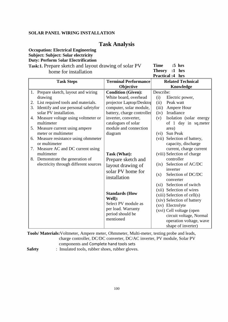
100
SOLAR PANEL WIRING INSTALLATION
Task Analysis Occupation: Electrical Engineering Subject: Subject: Solar electricity Duty: Perform Solar Electrification
Task:1. Prepare sketch and layout drawing of solar PV home for installation
Time :5 hrs Theory :1 hrs Practical :4 hrs
Task Steps Terminal Performance Objective
Related Technical Knowledge
1. Prepare sketch, layout and wiring drawing
2. List required tools and materials. 3. Identify and use personal safetyfor
solar PV installation. 4. Measure voltage using voltmeter or
multimeter 5. Measure current using ampere
meter or multimeter 6. Measure resistance using ohmmeter
or multimeter 7. Measure AC and DC current using
multimeter 8. Demonstrate the generation of
electricity through different sources
Condition (Given): White board, overhead projector Laptop/Desktop computer, solar module, battery, charge controller, inverter, converter, catalogues of solar module and connection diagram Task (What): Prepare sketch and layout drawing of solar PV home for installation Standards (How Well): Select PV module as per load. Warranty period should be mentioned
Describe: (i) Electric power, (ii) Peak watt (iii) Ampere Hour (iv) Irradiance (v) Isolation (solar energy
of 1 day in sq.meter area)
(vi) Sun Peak (vii) Selection of battery,
capacity, discharge current, charge current
(viii) Selection of charge controller
(ix) Selection of AC/DC inverter
(x) Selection of DC/DC converter
(xi) Selection of switch (xii) Selection of wires (xiii) Selection of cell(s) (xiv) Selection of battery (xv) Electrolyte (xvi) Cell voltage (open
circuit voltage, Normal operation voltage, wave shape of inverter)
Tools/ Materials:Voltmeter, Ampere meter, Ohmmeter, Multi-meter, testing probe and leads, charge controller, DC/DC converter, DC/AC inverter, PV module, Solar PV components and Complete hand tools sets
Safety : Insulated tools, rubber shoes, rubber gloves.
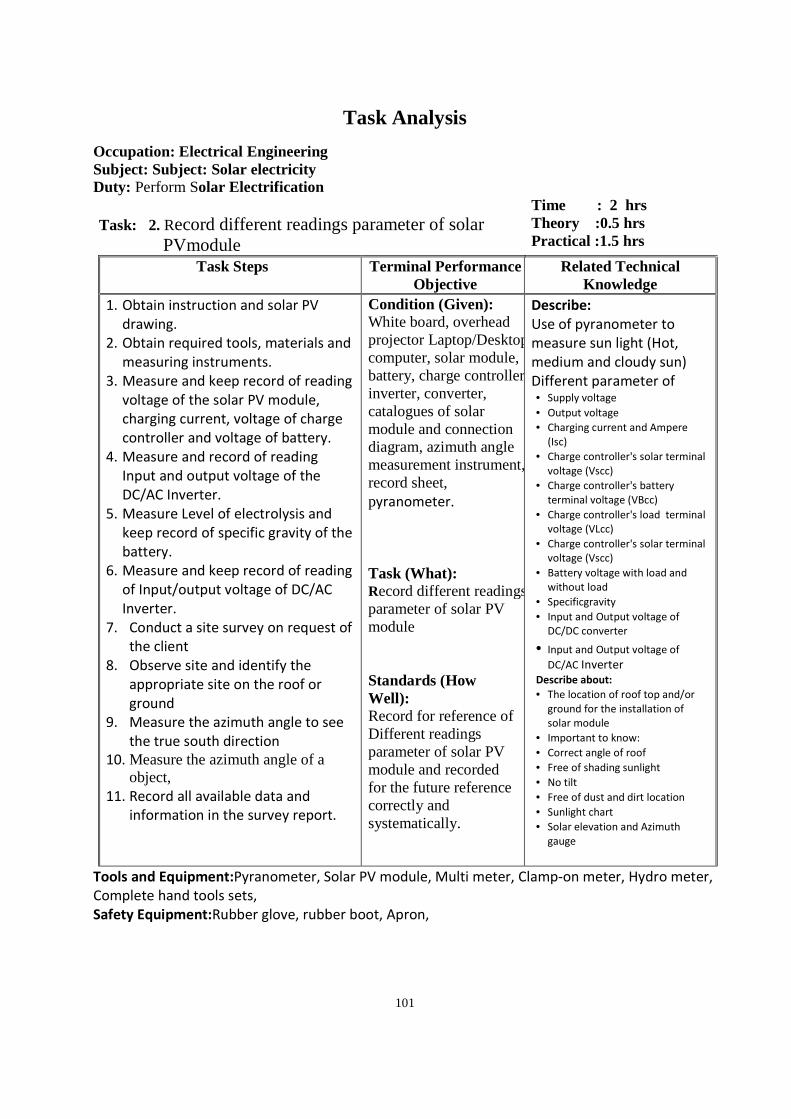
101
Task Analysis
Occupation: Electrical Engineering Subject: Subject: Solar electricity Duty: Perform Solar Electrification
Task: 2. Record different readings parameter of solar
PVmodule
Time : 2 hrs Theory :0.5 hrs Practical :1.5 hrs
Task Steps Terminal Performance Objective
Related Technical Knowledge
1. Obtain instruction and solar PV
drawing.
2. Obtain required tools, materials and
measuring instruments.
3. Measure and keep record of reading
voltage of the solar PV module,
charging current, voltage of charge
controller and voltage of battery.
4. Measure and record of reading
Input and output voltage of the
DC/AC Inverter.
5. Measure Level of electrolysis and
keep record of specific gravity of the
battery.
6. Measure and keep record of reading
of Input/output voltage of DC/AC
Inverter.
7. Conduct a site survey on request of
the client
8. Observe site and identify the
appropriate site on the roof or
ground
9. Measure the azimuth angle to see
the true south direction
10. Measure the azimuth angle of a object,
11. Record all available data and
information in the survey report.
Condition (Given): White board, overhead projector Laptop/Desktop computer, solar module, battery, charge controller, inverter, converter, catalogues of solar module and connection diagram, azimuth angle measurement instrument, record sheet, pyranometer. Task (What): Record different readings parameter of solar PV module Standards (How Well): Record for reference of Different readings parameter of solar PV module and recorded for the future reference correctly and systematically.
Describe:
Use of pyranometer to
measure sun light (Hot,
medium and cloudy sun)
Different parameter of • Supply voltage
• Output voltage
• Charging current and Ampere
(Isc)
• Charge controller's solar terminal
voltage (Vscc)
• Charge controller's battery
terminal voltage (VBcc)
• Charge controller's load terminal
voltage (VLcc)
• Charge controller's solar terminal
voltage (Vscc)
• Battery voltage with load and
without load
• Specificgravity
• Input and Output voltage of
DC/DC converter
• Input and Output voltage of
DC/AC Inverter Describe about:
• The location of roof top and/or
ground for the installation of
solar module
• Important to know:
• Correct angle of roof
• Free of shading sunlight
• No tilt
• Free of dust and dirt location
• Sunlight chart
• Solar elevation and Azimuth
gauge
Tools and Equipment:Pyranometer, Solar PV module, Multi meter, Clamp-on meter, Hydro meter,
Complete hand tools sets,
Safety Equipment:Rubber glove, rubber boot, Apron,
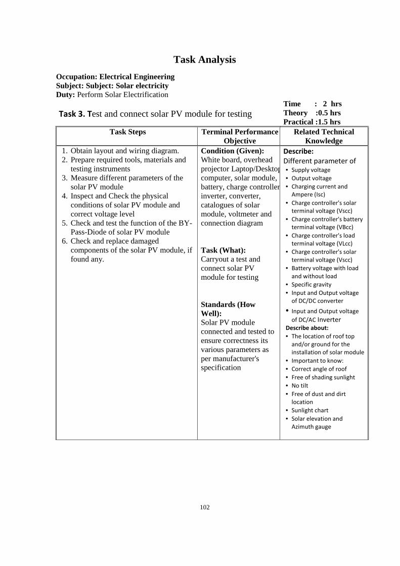
102
Task Analysis
Occupation: Electrical Engineering Subject: Subject: Solar electricity Duty: Perform Solar Electrification Task 3. Test and connect solar PV module for testing
Time : 2 hrs Theory :0.5 hrs Practical :1.5 hrs
Task Steps Terminal Performance Objective
Related Technical Knowledge
1. Obtain layout and wiring diagram. 2. Prepare required tools, materials and
testing instruments 3. Measure different parameters of the
solar PV module 4. Inspect and Check the physical
conditions of solar PV module and correct voltage level
5. Check and test the function of the BY-Pass-Diode of solar PV module
6. Check and replace damaged components of the solar PV module, if found any.
Condition (Given): White board, overhead projector Laptop/Desktop computer, solar module, battery, charge controller, inverter, converter, catalogues of solar module, voltmeter and connection diagram Task (What): Carryout a test and connect solar PV module for testing Standards (How Well): Solar PV module connected and tested to ensure correctness its various parameters as per manufacturer's specification
Describe:
Different parameter of • Supply voltage
• Output voltage
• Charging current and
Ampere (Isc)
• Charge controller's solar
terminal voltage (Vscc)
• Charge controller's battery
terminal voltage (VBcc)
• Charge controller's load
terminal voltage (VLcc)
• Charge controller's solar
terminal voltage (Vscc)
• Battery voltage with load
and without load
• Specific gravity
• Input and Output voltage
of DC/DC converter
• Input and Output voltage
of DC/AC Inverter Describe about:
• The location of roof top
and/or ground for the
installation of solar module
• Important to know:
• Correct angle of roof
• Free of shading sunlight
• No tilt
• Free of dust and dirt
location
• Sunlight chart
• Solar elevation and
Azimuth gauge
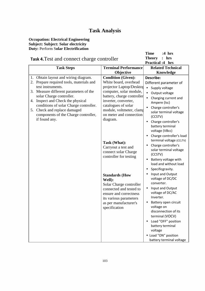
103
Task Analysis
Occupation: Electrical Engineering Subject: Subject: Solar electricity Duty: Perform Solar Electrification
Task 4.Test and connect charge controller
Time :4 hrs Theory : hrs Practical :4 hrs
Task Steps Terminal Performance Objective
Related Technical Knowledge
1. Obtain layout and wiring diagram. 2. Prepare required tools, materials and
test instruments. 3. Measure different parameters of the
solar Charge controller. 4. Inspect and Check the physical
conditions of solar Charge controller. 5. Check and replace damaged
components of the Charge controller, if found any.
Condition (Given): White board, overhead projector Laptop/Desktop computer, solar module, battery, charge controller, inverter, converter, catalogues of solar module, voltmeter, clamp on meter and connection diagram. Task (What): Carryout a test and connect solar Charge controller for testing Standards (How Well): Solar Charge controller connected and tested to ensure and correctness its various parameters as per manufacturer's specification
Describe:
Different parameter of
• Supply voltage
• Output voltage
• Charging current and
Ampere (Isc)
• Charge controller's
solar terminal voltage
(CCSTV)
• Charge controller's
battery terminal
voltage (VBcc)
• Charge controller's load
terminal voltage (CCLTV)
• Charge controller's
solar terminal voltage
(CCSTV)
• Battery voltage with
load and without load
• Specificgravity.
• Input and Output
voltage of DC/DC
converter.
• Input and Output
voltage of DC/AC
Inverter.
• Battery open circuit
voltage on
disconnection of its
terminal (VOCV)
• Load "OFF" position
battery terminal
voltage
• Load "ON" position
battery terminal voltage
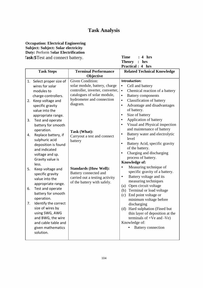
104
Task Analysis
Occupation: Electrical Engineering Subject: Subject: Solar electricity Duty: Perform Solar Electrification
Task:5Test and connect battery. Time : 4 hrs Theory : hrs Practical : 4 hrs
Task Steps Terminal Performance Objective
Related Technical Knowledge
1. Select proper size of
wires for solar
modules to
charge-controllers.
2. Keep voltage and
specific gravity
value into the
appropriate range.
3. Test and operate
battery for smooth
operation.
4. Replace battery, if
sulphuric acid
deposition is found
and indicated
voltage and sp.
Gravity value is
less.
5. Keep voltage and
specific gravity
value into the
appropriate range.
6. Test and operate
battery for smooth
operation.
7. Identify the correct
size of wires by
using SWG, AWG
and BWG, the wire
and cable table and
given mathematics
solution.
Given Condition: solar module, battery, charge controller, inverter, converter, catalogues of solar module, hydrometer and connection diagram. Task (What): Carryout a test and connect battery Standards (How Well): Battery connected and carried out a testing activity of the battery with safely.
Introduction: • Cell and battery • Chemical reaction of a battery • Battery components • Classification of battery • Advantage and disadvantages
of battery. • Size of battery • Application of battery • Visual and Physical inspection
and maintenance of battery • Battery water and electrolytic
level • Battery Acid, specific gravity
of the battery. • Charging and discharging
process of battery. Knowledge of: • Measuring technique of
specific gravity of a battery. • Battery voltage and its
measuring techniques (a) Open circuit voltage (b) Terminal or load voltage (c) End point voltage or
minimum voltage before discharging
(d) Hard sulphation (Fined but thin layer of deposition at the terminals of +Ve and -Ve)
Knowledge of: • Battery connection
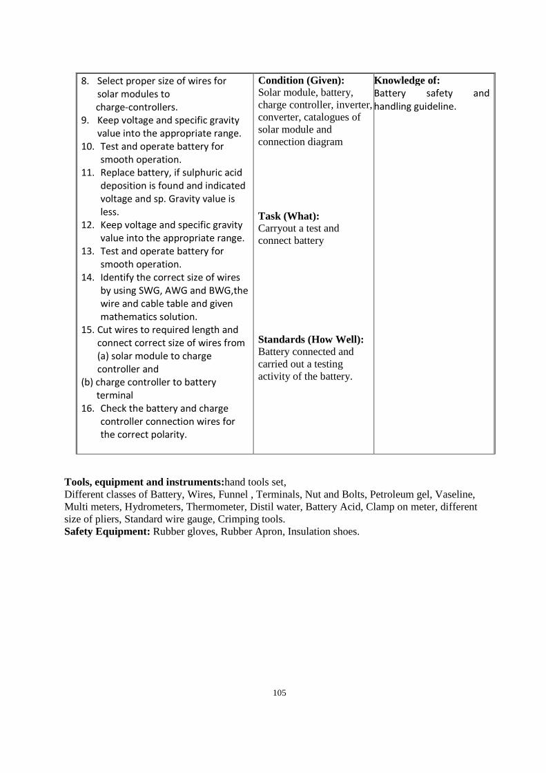
105
8. Select proper size of wires for
solar modules to
charge-controllers.
9. Keep voltage and specific gravity
value into the appropriate range.
10. Test and operate battery for
smooth operation.
11. Replace battery, if sulphuric acid
deposition is found and indicated
voltage and sp. Gravity value is
less.
12. Keep voltage and specific gravity
value into the appropriate range.
13. Test and operate battery for
smooth operation.
14. Identify the correct size of wires
by using SWG, AWG and BWG,the
wire and cable table and given
mathematics solution.
15. Cut wires to required length and
connect correct size of wires from
(a) solar module to charge
controller and
(b) charge controller to battery
terminal
16. Check the battery and charge
controller connection wires for
the correct polarity.
Condition (Given): Solar module, battery, charge controller, inverter, converter, catalogues of solar module and connection diagram Task (What): Carryout a test and connect battery Standards (How Well): Battery connected and carried out a testing activity of the battery.
Knowledge of: Battery safety and
handling guideline.
Tools, equipment and instruments:hand tools set, Different classes of Battery, Wires, Funnel , Terminals, Nut and Bolts, Petroleum gel, Vaseline, Multi meters, Hydrometers, Thermometer, Distil water, Battery Acid, Clamp on meter, different size of pliers, Standard wire gauge, Crimping tools. Safety Equipment: Rubber gloves, Rubber Apron, Insulation shoes.
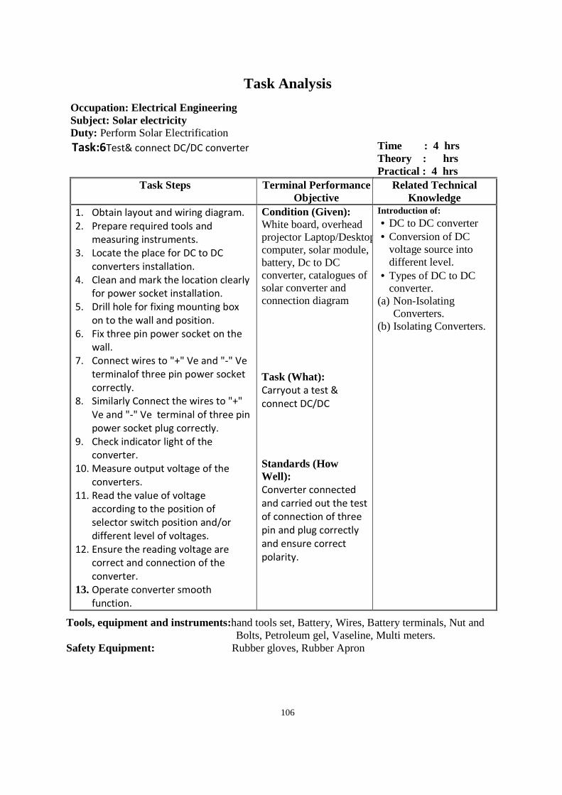
106
Task Analysis
Occupation: Electrical Engineering Subject: Solar electricity Duty: Perform Solar Electrification
Task: Task:6Test& connect DC/DC converter Time : 4 hrs Theory : hrs Practical : 4 hrs
Task Steps Terminal Performance Objective
Related Technical Knowledge
1. Obtain layout and wiring diagram.
2. Prepare required tools and
measuring instruments.
3. Locate the place for DC to DC
converters installation.
4. Clean and mark the location clearly
for power socket installation.
5. Drill hole for fixing mounting box
on to the wall and position.
6. Fix three pin power socket on the
wall.
7. Connect wires to "+" Ve and "-" Ve
terminalof three pin power socket
correctly.
8. Similarly Connect the wires to "+"
Ve and "-" Ve terminal of three pin
power socket plug correctly.
9. Check indicator light of the
converter.
10. Measure output voltage of the
converters.
11. Read the value of voltage
according to the position of
selector switch position and/or
different level of voltages.
12. Ensure the reading voltage are
correct and connection of the
converter.
13. Operate converter smooth
function.
Condition (Given): White board, overhead projector Laptop/Desktop computer, solar module, battery, Dc to DC converter, catalogues of solar converter and connection diagram Task (What): Carryout a test &
connect DC/DC
Standards (How Well): Converter connected
and carried out the test
of connection of three
pin and plug correctly
and ensure correct
polarity.
Introduction of: • DC to DC converter • Conversion of DC
voltage source into different level.
• Types of DC to DC converter.
(a) Non-Isolating Converters.
(b) Isolating Converters.
Tools, equipment and instruments:hand tools set, Battery, Wires, Battery terminals, Nut and Bolts, Petroleum gel, Vaseline, Multi meters.
Safety Equipment: Rubber gloves, Rubber Apron
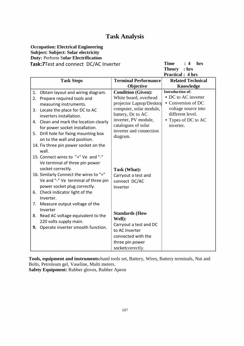
107
Task Analysis
Occupation: Electrical Engineering Subject: Subject: Solar electricity Duty: Perform Solar Electrification
Task:7Test and connect DC/AC Inverter Time : 4 hrs Theory : hrs Practical : 4 hrs
Task Steps Terminal Performance Objective
Related Technical Knowledge
1. Obtain layout and wiring diagram.
2. Prepare required tools and
measuring instruments.
3. Locate the place for DC to AC
inverters installation.
4. Clean and mark the location clearly
for power socket installation.
5. Drill hole for fixing mounting box
on to the wall and position.
14. Fix three pin power socket on the
wall.
15. Connect wires to "+" Ve and "-"
Ve terminal of three pin power
socket correctly.
16. Similarly Connect the wires to "+"
Ve and "-" Ve terminal of three pin
power socket plug correctly.
6. Check indicator light of the
Inverter.
7. Measure output voltage of the
Inverter
8. Read AC voltage equivalent to the
220 volts supply main.
9. Operate inverter smooth function.
Condition (Given): White board, overhead projector Laptop/Desktop computer, solar module, battery, Dc to AC inverter, PV module, catalogues of solar inverter and connection diagram. Task (What): Carryout a test and
connect DC/AC
Inverter
Standards (How Well): Carryout a test and DC
to AC Inverter
connected with the
three pin power
socketcorrectly.
Introduction of: • DC to AC inverter • Conversion of DC
voltage source into different level.
• Types of DC to AC inverter.
Tools, equipment and instruments:hand tools set, Battery, Wires, Battery terminals, Nut and Bolts, Petroleum gel, Vaseline, Multi meters. Safety Equipment: Rubber gloves, Rubber Apron
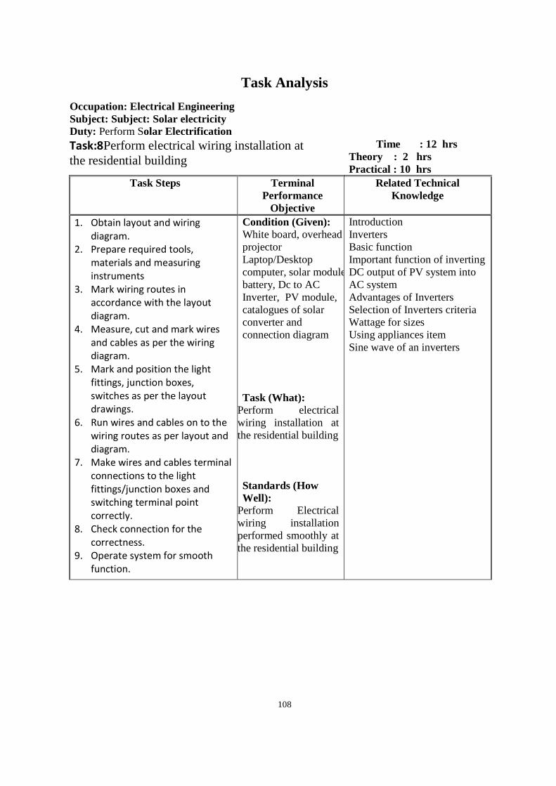
108
Task Analysis
Occupation: Electrical Engineering Subject: Subject: Solar electricity Duty: Perform Solar Electrification
Task:8Perform electrical wiring installation at the residential building
Time : 12 hrs Theory : 2 hrs Practical : 10 hrs
Task Steps Terminal Performance
Objective
Related Technical Knowledge
1. Obtain layout and wiring
diagram.
2. Prepare required tools,
materials and measuring
instruments
3. Mark wiring routes in
accordance with the layout
diagram.
4. Measure, cut and mark wires
and cables as per the wiring
diagram.
5. Mark and position the light
fittings, junction boxes,
switches as per the layout
drawings.
6. Run wires and cables on to the
wiring routes as per layout and
diagram.
7. Make wires and cables terminal
connections to the light
fittings/junction boxes and
switching terminal point
correctly.
8. Check connection for the
correctness.
9. Operate system for smooth
function.
Condition (Given): White board, overhead projector Laptop/Desktop computer, solar module, battery, Dc to AC Inverter, PV module, catalogues of solar converter and connection diagram Task (What):
Perform electrical wiring installation at the residential building Standards (How Well):
Perform Electrical wiring installation performed smoothly at the residential building
Introduction Inverters Basic function Important function of inverting DC output of PV system into AC system Advantages of Inverters Selection of Inverters criteria Wattage for sizes Using appliances item Sine wave of an inverters
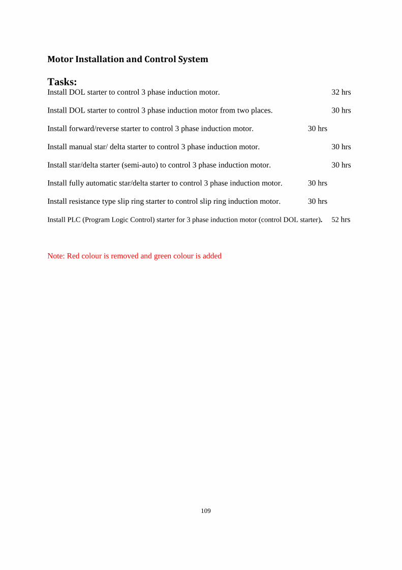
109
Motor Installation and Control System
Tasks: Install DOL starter to control 3 phase induction motor. 32 hrs
Install DOL starter to control 3 phase induction motor from two places. 30 hrs
Install forward/reverse starter to control 3 phase induction motor. 30 hrs
Install manual star/ delta starter to control 3 phase induction motor. 30 hrs
Install star/delta starter (semi-auto) to control 3 phase induction motor. 30 hrs
Install fully automatic star/delta starter to control 3 phase induction motor. 30 hrs
Install resistance type slip ring starter to control slip ring induction motor. 30 hrs
Install PLC (Program Logic Control) starter for 3 phase induction motor (control DOL starter). 52 hrs
Note: Red colour is removed and green colour is added
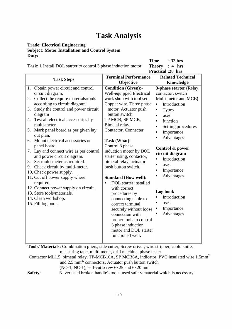
110
Task Analysis
Trade: Electrical Engineering Subject: Motor Installation and Control System Duty: Task: 1 Install DOL starter to control 3 phase induction motor.
Time : 32 hrs Theory : 4 hrs Practical :28 hrs
Task Steps Terminal Performance Objective
Related Technical Knowledge
1. Obtain power circuit and control circuit diagram.
2. Collect the require materials/tools according to circuit diagram.
3. Study the control and power circuit diagram
4. Test all electrical accessories by multi-meter.
5. Mark panel board as per given lay out plan.
6. Mount electrical accessories on panel board.
7. Lay and connect wire as per control and power circuit diagram.
8. Set multi-meter as required. 9. Check circuit by multi-meter. 10. Check power supply. 11. Cut off power supply where
required. 12. Connect power supply on circuit. 13. Store tools/materials. 14. Clean workshop. 15. Fill log book.
Condition (Given):- Well-equipped Electrical work shop with tool set. Copper wire, Three phase
motor, Actuator push button switch,
TP MCB, SP MCB, Bimetal relay, Contactor, Connecter Task (What): Control 3 phase induction motor by DOL starter using, contactor, bimetal relay, actuator push button switch. Standard (How well): • DOL starter installed
with correct procedures by connecting cable to correct terminal securely without loose connection with proper tools to control 3 phase induction motor and DOL starter functioned well.
3-phase starter (Relay, contactor, switch Multi-meter and MCB) • Introduction • Types • uses • function • Setting procedures • Importance • Advantages Control & power circuit diagram • Introduction • uses • Importance • Advantages Log book • Introduction • uses • Importance • Advantages
Tools/ Materials: Combination pliers, side cutter, Screw driver, wire stripper, cable knife, measuring tape, multi meter, drill machine, phase tester
Contactor ML1.5, bimetal relay, TP-MCB16A, SP MCB6A, indicator, PVC insulated wire 1.5mm2 and 2.5 mm2, connectors, Actuator push button switch
(NO-1, NC-1), self-cut screw 6x25 and 6x20mm Safety: Never used broken handle's tools, used safety material which is necessary
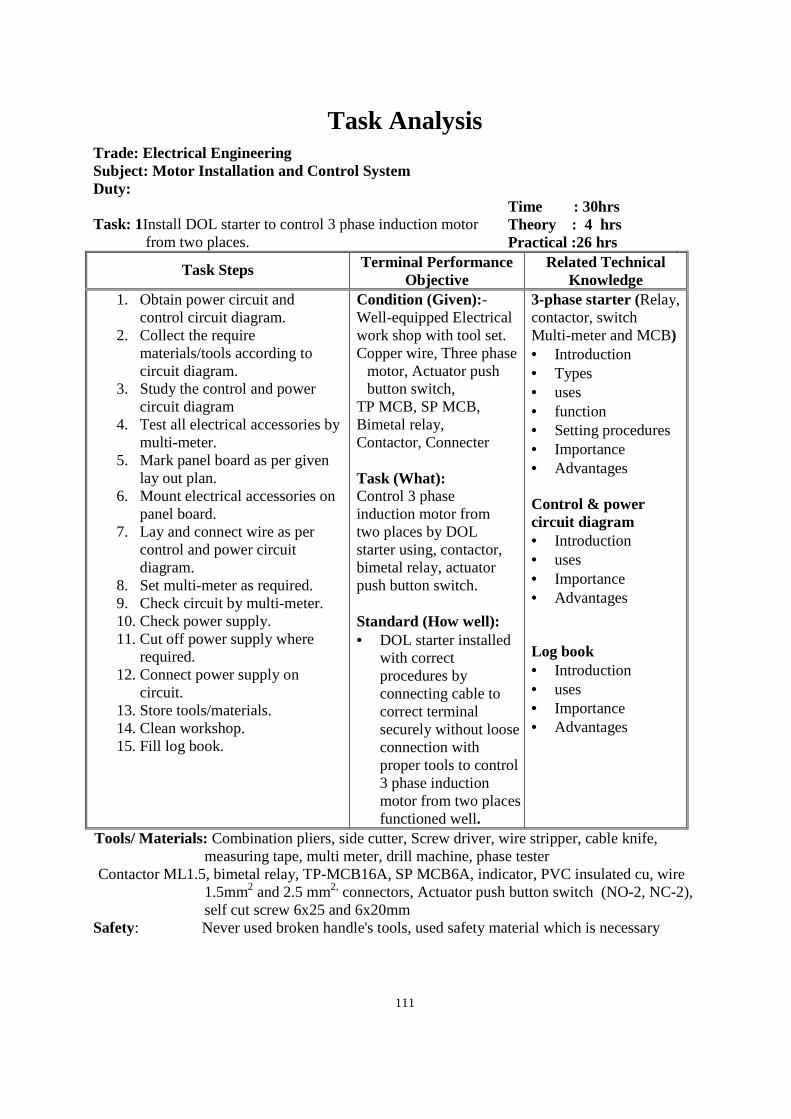
111
Task Analysis
Trade: Electrical Engineering Subject: Motor Installation and Control System Duty: Task: 1Install DOL starter to control 3 phase induction motor
from two places.
Time : 30hrs Theory : 4 hrs Practical :26 hrs
Task Steps Terminal Performance Objective
Related Technical Knowledge
1. Obtain power circuit and control circuit diagram.
2. Collect the require materials/tools according to circuit diagram.
3. Study the control and power circuit diagram
4. Test all electrical accessories by multi-meter.
5. Mark panel board as per given lay out plan.
6. Mount electrical accessories on panel board.
7. Lay and connect wire as per control and power circuit diagram.
8. Set multi-meter as required. 9. Check circuit by multi-meter. 10. Check power supply. 11. Cut off power supply where
required. 12. Connect power supply on
circuit. 13. Store tools/materials. 14. Clean workshop. 15. Fill log book.
Condition (Given):- Well-equipped Electrical work shop with tool set. Copper wire, Three phase
motor, Actuator push button switch,
TP MCB, SP MCB, Bimetal relay, Contactor, Connecter Task (What): Control 3 phase induction motor from two places by DOL starter using, contactor, bimetal relay, actuator push button switch. Standard (How well): • DOL starter installed
with correct procedures by connecting cable to correct terminal securely without loose connection with proper tools to control 3 phase induction motor from two places functioned well.
3-phase starter (Relay, contactor, switch Multi-meter and MCB) • Introduction • Types • uses • function • Setting procedures • Importance • Advantages Control & power circuit diagram • Introduction • uses • Importance • Advantages Log book • Introduction • uses • Importance • Advantages
Tools/ Materials: Combination pliers, side cutter, Screw driver, wire stripper, cable knife, measuring tape, multi meter, drill machine, phase tester
Contactor ML1.5, bimetal relay, TP-MCB16A, SP MCB6A, indicator, PVC insulated cu, wire 1.5mm2 and 2.5 mm2, connectors, Actuator push button switch (NO-2, NC-2), self cut screw 6x25 and 6x20mm
Safety: Never used broken handle's tools, used safety material which is necessary
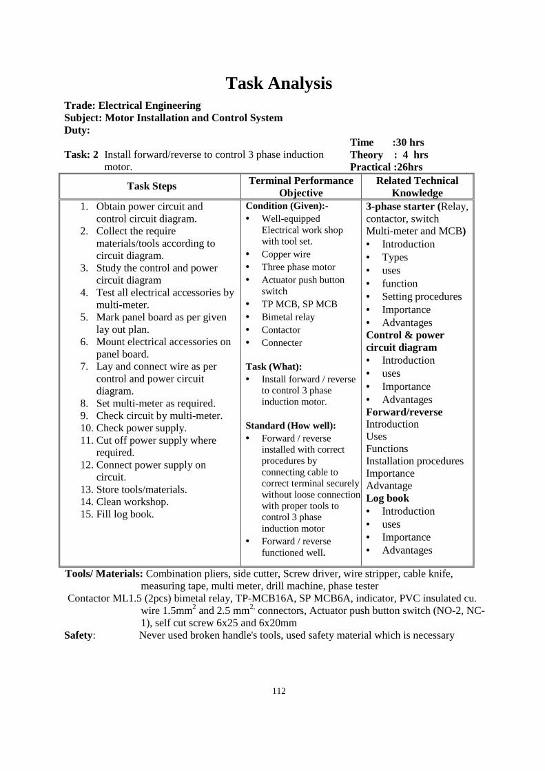
112
Task Analysis
Trade: Electrical Engineering Subject: Motor Installation and Control System Duty: Task: 2 Install forward/reverse to control 3 phase induction
motor.
Time :30 hrs Theory : 4 hrs Practical :26hrs
Task Steps Terminal Performance Objective
Related Technical Knowledge
1. Obtain power circuit and control circuit diagram.
2. Collect the require materials/tools according to circuit diagram.
3. Study the control and power circuit diagram
4. Test all electrical accessories by multi-meter.
5. Mark panel board as per given lay out plan.
6. Mount electrical accessories on panel board.
7. Lay and connect wire as per control and power circuit diagram.
8. Set multi-meter as required. 9. Check circuit by multi-meter. 10. Check power supply. 11. Cut off power supply where
required. 12. Connect power supply on
circuit. 13. Store tools/materials. 14. Clean workshop. 15. Fill log book.
Condition (Given):- • Well-equipped
Electrical work shop with tool set.
• Copper wire • Three phase motor • Actuator push button
switch • TP MCB, SP MCB • Bimetal relay • Contactor • Connecter Task (What): • Install forward / reverse
to control 3 phase induction motor.
Standard (How well): • Forward / reverse
installed with correct procedures by connecting cable to correct terminal securely without loose connection with proper tools to control 3 phase induction motor
• Forward / reverse functioned well.
3-phase starter (Relay, contactor, switch Multi-meter and MCB) • Introduction • Types • uses • function • Setting procedures • Importance • Advantages Control & power circuit diagram • Introduction • uses • Importance • Advantages Forward/reverse Introduction Uses Functions Installation procedures Importance Advantage Log book • Introduction • uses • Importance • Advantages
Tools/ Materials: Combination pliers, side cutter, Screw driver, wire stripper, cable knife, measuring tape, multi meter, drill machine, phase tester
Contactor ML1.5 (2pcs) bimetal relay, TP-MCB16A, SP MCB6A, indicator, PVC insulated cu. wire 1.5mm2 and 2.5 mm2, connectors, Actuator push button switch (NO-2, NC-1), self cut screw 6x25 and 6x20mm
Safety: Never used broken handle's tools, used safety material which is necessary
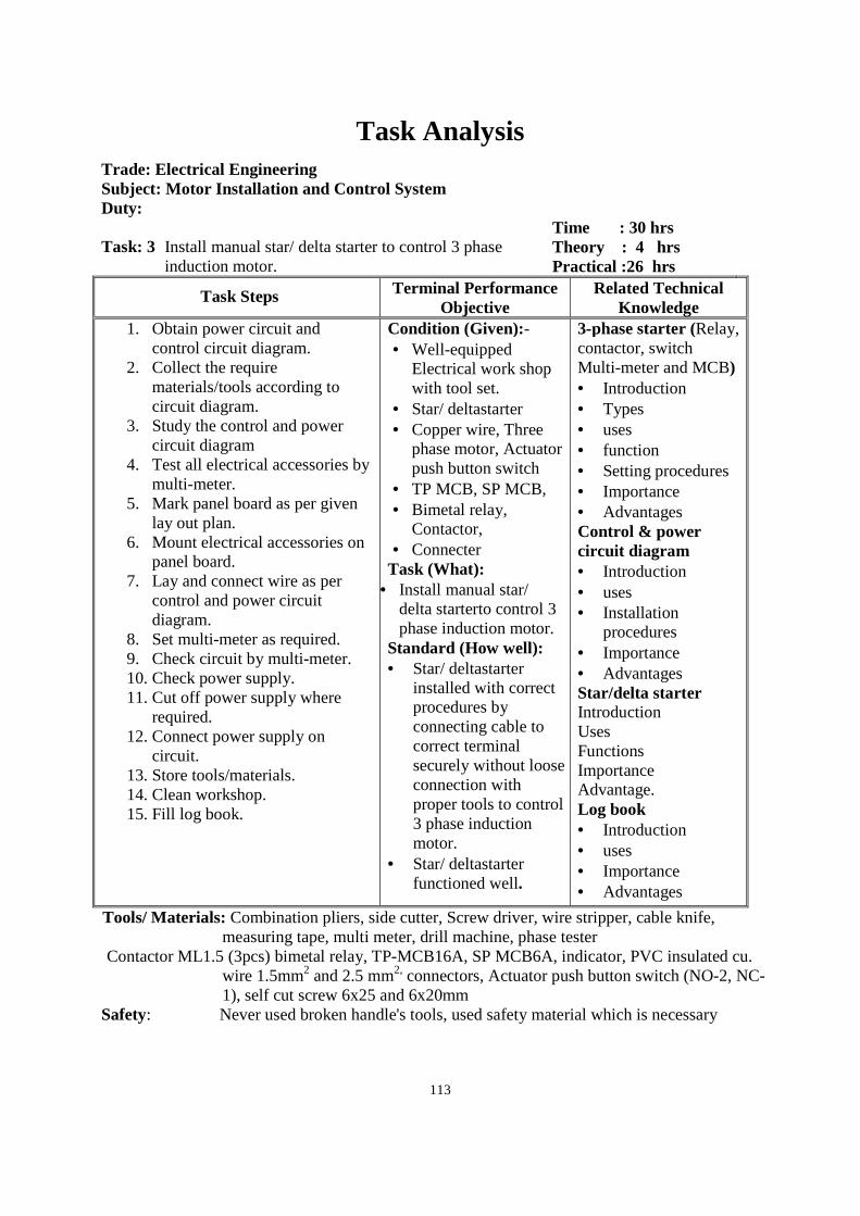
113
Task Analysis
Trade: Electrical Engineering Subject: Motor Installation and Control System Duty: Task: 3 Install manual star/ delta starter to control 3 phase
induction motor.
Time : 30 hrs Theory : 4 hrs Practical :26 hrs
Task Steps Terminal Performance Objective
Related Technical Knowledge
1. Obtain power circuit and control circuit diagram.
2. Collect the require materials/tools according to circuit diagram.
3. Study the control and power circuit diagram
4. Test all electrical accessories by multi-meter.
5. Mark panel board as per given lay out plan.
6. Mount electrical accessories on panel board.
7. Lay and connect wire as per control and power circuit diagram.
8. Set multi-meter as required. 9. Check circuit by multi-meter. 10. Check power supply. 11. Cut off power supply where
required. 12. Connect power supply on
circuit. 13. Store tools/materials. 14. Clean workshop. 15. Fill log book.
Condition (Given):- • Well-equipped
Electrical work shop with tool set.
• Star/ deltastarter • Copper wire, Three
phase motor, Actuator push button switch
• TP MCB, SP MCB, • Bimetal relay,
Contactor, • Connecter
Task (What): • Install manual star/
delta starterto control 3 phase induction motor.
Standard (How well): • Star/ deltastarter
installed with correct procedures by connecting cable to correct terminal securely without loose connection with proper tools to control 3 phase induction motor.
• Star/ deltastarter functioned well.
3-phase starter (Relay, contactor, switch Multi-meter and MCB) • Introduction • Types • uses • function • Setting procedures • Importance • Advantages Control & power circuit diagram • Introduction • uses • Installation
procedures • Importance • Advantages Star/delta starter Introduction Uses Functions Importance Advantage. Log book • Introduction • uses • Importance • Advantages
Tools/ Materials: Combination pliers, side cutter, Screw driver, wire stripper, cable knife, measuring tape, multi meter, drill machine, phase tester
Contactor ML1.5 (3pcs) bimetal relay, TP-MCB16A, SP MCB6A, indicator, PVC insulated cu. wire 1.5mm2 and 2.5 mm2, connectors, Actuator push button switch (NO-2, NC-1), self cut screw 6x25 and 6x20mm
Safety: Never used broken handle's tools, used safety material which is necessary
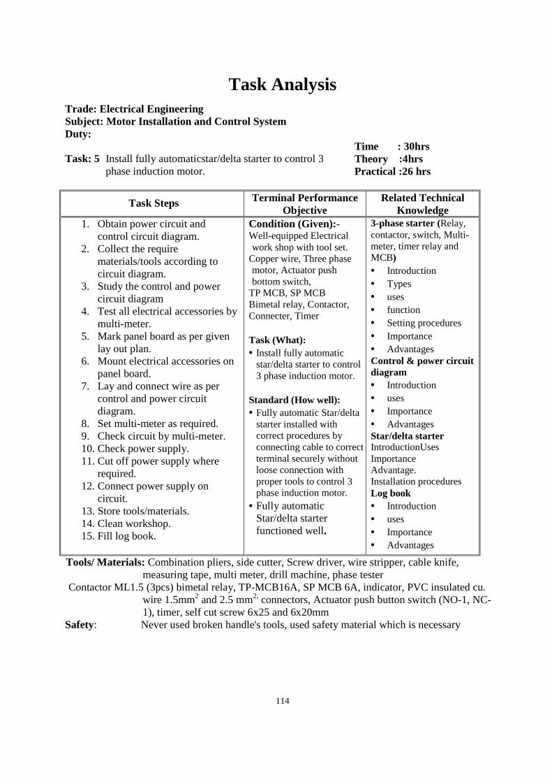
114
Task Analysis
Trade: Electrical Engineering Subject: Motor Installation and Control System Duty: Task: 5 Install fully automaticstar/delta starter to control 3
phase induction motor.
Time : 30hrs Theory :4hrs Practical :26 hrs
Task Steps Terminal Performance Objective
Related Technical Knowledge
1. Obtain power circuit and control circuit diagram.
2. Collect the require materials/tools according to circuit diagram.
3. Study the control and power circuit diagram
4. Test all electrical accessories by multi-meter.
5. Mark panel board as per given lay out plan.
6. Mount electrical accessories on panel board.
7. Lay and connect wire as per control and power circuit diagram.
8. Set multi-meter as required. 9. Check circuit by multi-meter. 10. Check power supply. 11. Cut off power supply where
required. 12. Connect power supply on
circuit. 13. Store tools/materials. 14. Clean workshop. 15. Fill log book.
Condition (Given):- Well-equipped Electrical work shop with tool set.
Copper wire, Three phase motor, Actuator push bottom switch,
TP MCB, SP MCB Bimetal relay, Contactor, Connecter, Timer Task (What): • Install fully automatic
star/delta starter to control 3 phase induction motor.
Standard (How well): • Fully automatic Star/delta
starter installed with correct procedures by connecting cable to correct terminal securely without loose connection with proper tools to control 3 phase induction motor.
• Fully automatic Star/delta starter functioned well.
3-phase starter (Relay, contactor, switch, Multi-meter, timer relay and MCB) • Introduction • Types • uses • function • Setting procedures • Importance • Advantages Control & power circuit diagram • Introduction • uses • Importance • Advantages Star/delta starter IntroductionUses Importance Advantage. Installation procedures Log book • Introduction • uses • Importance • Advantages
Tools/ Materials: Combination pliers, side cutter, Screw driver, wire stripper, cable knife, measuring tape, multi meter, drill machine, phase tester
Contactor ML1.5 (3pcs) bimetal relay, TP-MCB16A, SP MCB 6A, indicator, PVC insulated cu. wire 1.5mm2 and 2.5 mm2, connectors, Actuator push button switch (NO-1, NC-1), timer, self cut screw 6x25 and 6x20mm
Safety: Never used broken handle's tools, used safety material which is necessary
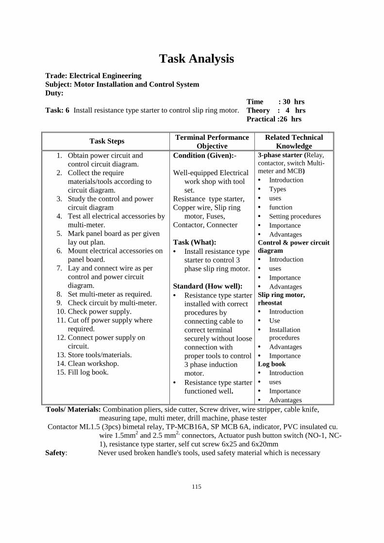
115
Task Analysis
Trade: Electrical Engineering Subject: Motor Installation and Control System Duty: Task: 6 Install resistance type starter to control slip ring motor.
Time : 30 hrs Theory : 4 hrs Practical :26 hrs
Task Steps Terminal Performance Objective
Related Technical Knowledge
1. Obtain power circuit and control circuit diagram.
2. Collect the require materials/tools according to circuit diagram.
3. Study the control and power circuit diagram
4. Test all electrical accessories by multi-meter.
5. Mark panel board as per given lay out plan.
6. Mount electrical accessories on panel board.
7. Lay and connect wire as per control and power circuit diagram.
8. Set multi-meter as required. 9. Check circuit by multi-meter. 10. Check power supply. 11. Cut off power supply where
required. 12. Connect power supply on
circuit. 13. Store tools/materials. 14. Clean workshop. 15. Fill log book.
Condition (Given):- Well-equipped Electrical
work shop with tool set.
Resistance type starter, Copper wire, Slip ring
motor, Fuses, Contactor, Connecter Task (What): • Install resistance type
starter to control 3 phase slip ring motor.
Standard (How well): • Resistance type starter
installed with correct procedures by connecting cable to correct terminal securely without loose connection with proper tools to control 3 phase induction motor.
• Resistance type starter functioned well.
3-phase starter (Relay, contactor, switch Multi-meter and MCB) • Introduction • Types • uses • function • Setting procedures • Importance • Advantages Control & power circuit diagram • Introduction • uses • Importance • Advantages Slip ring motor, rheostat • Introduction • Use • Installation
procedures • Advantages • Importance Log book • Introduction • uses • Importance • Advantages
Tools/ Materials: Combination pliers, side cutter, Screw driver, wire stripper, cable knife, measuring tape, multi meter, drill machine, phase tester
Contactor ML1.5 (3pcs) bimetal relay, TP-MCB16A, SP MCB 6A, indicator, PVC insulated cu. wire 1.5mm2 and 2.5 mm2, connectors, Actuator push button switch (NO-1, NC-1), resistance type starter, self cut screw 6x25 and 6x20mm
Safety: Never used broken handle's tools, used safety material which is necessary
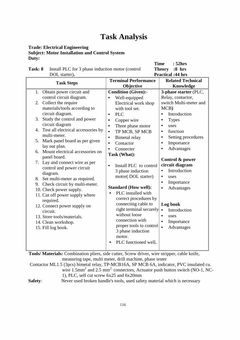
116
Task Analysis
Trade: Electrical Engineering Subject: Motor Installation and Control System Duty: Task: 8 Install PLC for 3 phase induction motor (control
DOL starter).
Time : 52hrs Theory :8 hrs Practical :44 hrs
Task Steps Terminal Performance Objective
Related Technical Knowledge
1. Obtain power circuit and control circuit diagram.
2. Collect the require materials/tools according to circuit diagram.
3. Study the control and power circuit diagram
4. Test all electrical accessories by multi-meter.
5. Mark panel board as per given lay out plan.
6. Mount electrical accessories on panel board.
7. Lay and connect wire as per control and power circuit diagram.
8. Set multi-meter as required. 9. Check circuit by multi-meter. 10. Check power supply. 11. Cut off power supply where
required. 12. Connect power supply on
circuit. 13. Store tools/materials. 14. Clean workshop. 15. Fill log book.
Condition (Given):- • Well-equipped
Electrical work shop with tool set.
• PLC • Copper wire • Three phase motor • TP MCB, SP MCB • Bimetal relay • Contactor • Connecter Task (What): • Install PLC to control
3 phase induction motor( DOL starter)
Standard (How well): • PLC installed with
correct procedures by connecting cable to right terminal securely without loose connection with proper tools to control 3 phase induction motor.
• PLC functioned well.
3-phase starter (PLC, Relay, contactor, switch Multi-meter and MCB) • Introduction • Types • uses • function • Setting procedures • Importance • Advantages Control & power circuit diagram • Introduction • uses • Importance • Advantages Log book • Introduction • uses • Importance • Advantages
Tools/ Materials: Combination pliers, side cutter, Screw driver, wire stripper, cable knife, measuring tape, multi meter, drill machine, phase tester
Contactor ML1.5 (3pcs) bimetal relay, TP-MCB16A, SP MCB 6A, indicator, PVC insulated cu. wire 1.5mm2 and 2.5 mm2, connectors, Actuator push button switch (NO-1, NC-1), PLC, self cut screw 6x25 and 6x20mm
Safety: Never used broken handle's tools, used safety material which is necessary
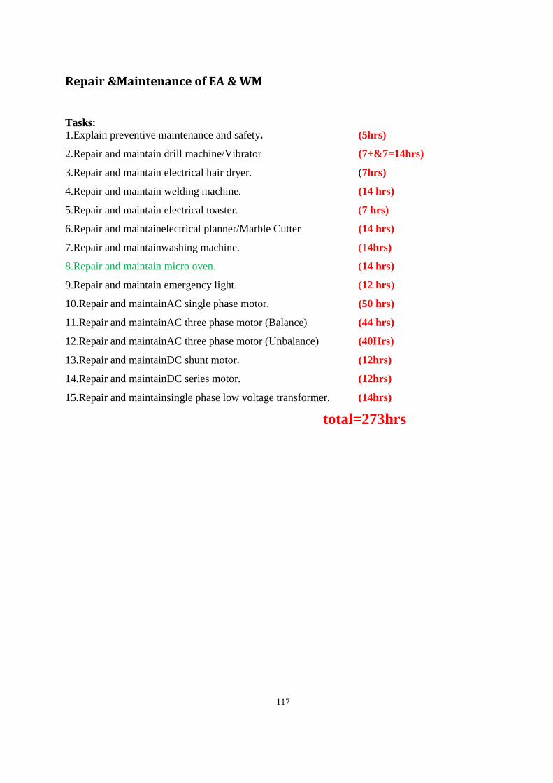
117
Repair &Maintenance of EA & WM
Tasks: 1.Explain preventive maintenance and safety. (5hrs)
2.Repair and maintain drill machine/Vibrator (7+&7=14hrs)
3.Repair and maintain electrical hair dryer. (7hrs)
4.Repair and maintain welding machine. (14 hrs)
5.Repair and maintain electrical toaster. (7 hrs)
6.Repair and maintainelectrical planner/Marble Cutter (14 hrs)
7.Repair and maintainwashing machine. (14hrs)
8.Repair and maintain micro oven. (14 hrs)
9.Repair and maintain emergency light. (12 hrs)
10.Repair and maintainAC single phase motor. (50 hrs)
11.Repair and maintainAC three phase motor (Balance) (44 hrs)
12.Repair and maintainAC three phase motor (Unbalance) (40Hrs)
13.Repair and maintainDC shunt motor. (12hrs)
14.Repair and maintainDC series motor. (12hrs)
15.Repair and maintainsingle phase low voltage transformer. (14hrs)
total=273hrs
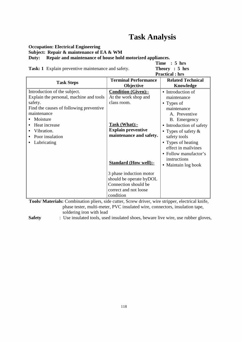
118
Task Analysis
Occupation: Electrical Engineering Subject: Repair & maintenance of EA & WM Duty: Repair and maintenance of house hold motorized appliances. Task: 1 Explain preventive maintenance and safety.
Time : 5 hrs Theory : 5 hrs Practical : hrs
Task Steps Terminal Performance Objective
Related Technical Knowledge
Introduction of the subject. Explain the personal, machine and tools safety. Find the causes of following preventive maintenance • Moisture • Heat increase • Vibration. • Poor insulation • Lubricating
Condition (Given):- At the work shop and class room. Task (What):- Explain preventive maintenance and safety. Standard (How well):- 3 phase induction motor should be operate byDOL Connection should be correct and not loose condition
• Introduction of maintenance
• Types of maintenance
A. Preventive B. Emergency
• Introduction of safety • Types of safety &
safety tools • Types of heating
effect in mailvines • Follow manufactor’s
instructions • Maintain log book
Tools/ Materials: Combination pliers, side cutter, Screw driver, wire stripper, electrical knife, phase tester, multi-meter, PVC insulated wire, connectors, insulation tape, soldering iron with lead
Safety : Use insulated tools, used insulated shoes, beware live wire, use rubber gloves,
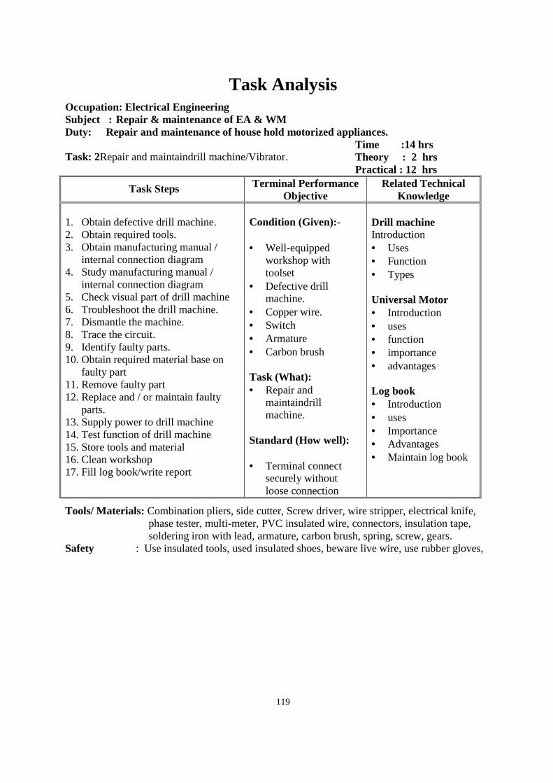
119
Task Analysis
Occupation: Electrical Engineering Subject : Repair & maintenance of EA & WM Duty: Repair and maintenance of house hold motorized appliances. Task: 2Repair and maintaindrill machine/Vibrator.
Time :14 hrs Theory : 2 hrs Practical : 12 hrs
Task Steps Terminal Performance Objective
Related Technical Knowledge
1. Obtain defective drill machine. 2. Obtain required tools. 3. Obtain manufacturing manual /
internal connection diagram 4. Study manufacturing manual /
internal connection diagram 5. Check visual part of drill machine 6. Troubleshoot the drill machine. 7. Dismantle the machine. 8. Trace the circuit. 9. Identify faulty parts. 10. Obtain required material base on
faulty part 11. Remove faulty part 12. Replace and / or maintain faulty
parts. 13. Supply power to drill machine 14. Test function of drill machine 15. Store tools and material 16. Clean workshop 17. Fill log book/write report
Condition (Given):- • Well-equipped
workshop with toolset
• Defective drill machine.
• Copper wire. • Switch • Armature • Carbon brush Task (What): • Repair and
maintaindrill machine.
Standard (How well): • Terminal connect
securely without loose connection
Drill machine Introduction • Uses • Function • Types
Universal Motor • Introduction • uses • function • importance • advantages Log book • Introduction • uses • Importance • Advantages • Maintain log book
Tools/ Materials: Combination pliers, side cutter, Screw driver, wire stripper, electrical knife, phase tester, multi-meter, PVC insulated wire, connectors, insulation tape, soldering iron with lead, armature, carbon brush, spring, screw, gears.
Safety : Use insulated tools, used insulated shoes, beware live wire, use rubber gloves,
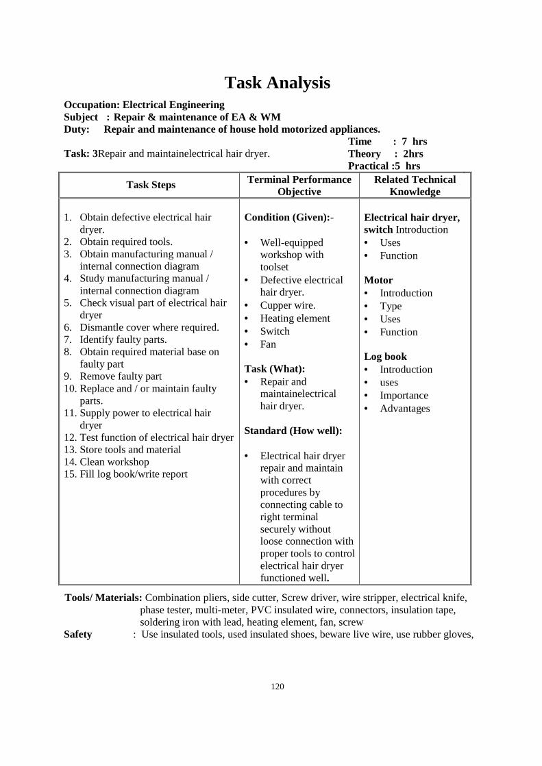
120
Task Analysis
Occupation: Electrical Engineering Subject : Repair & maintenance of EA & WM Duty: Repair and maintenance of house hold motorized appliances. Task: 3Repair and maintainelectrical hair dryer.
Time : 7 hrs Theory : 2hrs Practical :5 hrs
Task Steps Terminal Performance Objective
Related Technical Knowledge
1. Obtain defective electrical hair
dryer. 2. Obtain required tools. 3. Obtain manufacturing manual /
internal connection diagram 4. Study manufacturing manual /
internal connection diagram 5. Check visual part of electrical hair
dryer 6. Dismantle cover where required. 7. Identify faulty parts. 8. Obtain required material base on
faulty part 9. Remove faulty part 10. Replace and / or maintain faulty
parts. 11. Supply power to electrical hair
dryer 12. Test function of electrical hair dryer 13. Store tools and material 14. Clean workshop 15. Fill log book/write report
Condition (Given):- • Well-equipped
workshop with toolset
• Defective electrical hair dryer.
• Cupper wire. • Heating element • Switch • Fan Task (What): • Repair and
maintainelectrical hair dryer.
Standard (How well): • Electrical hair dryer
repair and maintain with correct procedures by connecting cable to right terminal securely without loose connection with proper tools to control electrical hair dryer functioned well.
Electrical hair dryer, switch Introduction • Uses • Function Motor • Introduction • Type • Uses • Function Log book • Introduction • uses • Importance • Advantages
Tools/ Materials: Combination pliers, side cutter, Screw driver, wire stripper, electrical knife, phase tester, multi-meter, PVC insulated wire, connectors, insulation tape, soldering iron with lead, heating element, fan, screw
Safety : Use insulated tools, used insulated shoes, beware live wire, use rubber gloves,
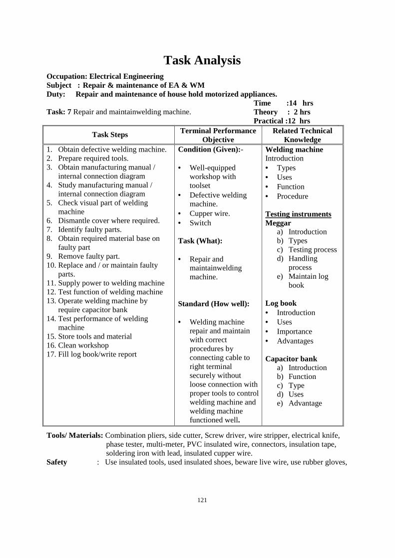
121
Task Analysis
Occupation: Electrical Engineering Subject : Repair & maintenance of EA & WM Duty: Repair and maintenance of house hold motorized appliances. Task: 7 Repair and maintainwelding machine.
Time :14 hrs Theory : 2 hrs Practical :12 hrs
Task Steps Terminal Performance Objective
Related Technical Knowledge
1. Obtain defective welding machine. 2. Prepare required tools. 3. Obtain manufacturing manual /
internal connection diagram 4. Study manufacturing manual /
internal connection diagram 5. Check visual part of welding
machine 6. Dismantle cover where required. 7. Identify faulty parts. 8. Obtain required material base on
faulty part 9. Remove faulty part. 10. Replace and / or maintain faulty
parts. 11. Supply power to welding machine 12. Test function of welding machine 13. Operate welding machine by
require capacitor bank 14. Test performance of welding
machine 15. Store tools and material 16. Clean workshop 17. Fill log book/write report
Condition (Given):- • Well-equipped
workshop with toolset
• Defective welding machine.
• Cupper wire. • Switch Task (What): • Repair and
maintainwelding machine.
Standard (How well): • Welding machine
repair and maintain with correct procedures by connecting cable to right terminal securely without loose connection with proper tools to control welding machine and welding machine functioned well.
Welding machine Introduction • Types • Uses • Function • Procedure Testing instruments Meggar
a) Introduction b) Types c) Testing process d) Handling
process e) Maintain log
book Log book • Introduction • Uses • Importance • Advantages Capacitor bank
a) Introduction b) Function c) Type d) Uses e) Advantage
Tools/ Materials: Combination pliers, side cutter, Screw driver, wire stripper, electrical knife, phase tester, multi-meter, PVC insulated wire, connectors, insulation tape, soldering iron with lead, insulated cupper wire.
Safety : Use insulated tools, used insulated shoes, beware live wire, use rubber gloves,
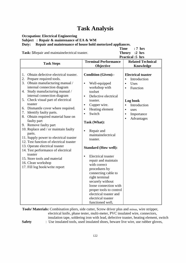
122
Task Analysis
Occupation: Electrical Engineering Subject : Repair & maintenance of EA & WM Duty: Repair and maintenance of house hold motorized appliances. Task: 5Repair and maintainelectrical toaster.
Time : 7 hrs Theory :2 hrs Practical :5 hrs
Task Steps Terminal Performance Objective
Related Technical Knowledge
1. Obtain defective electrical toaster. 2. Prepare required tools. 3. Obtain manufacturing manual /
internal connection diagram 4. Study manufacturing manual /
internal connection diagram 5. Check visual part of electrical
toaster 6. Dismantle cover where required. 7. Identify faulty parts. 8. Obtain required material base on
faulty part 9. Remove faulty part 10. Replace and / or maintain faulty
parts. 11. Supply power to electrical toaster 12. Test function of electrical toaster 13. Operate electrical toaster 14. Test performance of electrical
toaster 15. Store tools and material 16. Clean workshop 17. Fill log book/write report
Condition (Given):- • Well-equipped
workshop with toolset
• Defective electrical toaster.
• Cupper wire. • Heating element • Switch Task (What): • Repair and
maintainelectrical toaster.
Standard (How well): • Electrical toaster
repair and maintain with correct procedures by connecting cable to right terminal securely without loose connection with proper tools to control electrical toaster and electrical toaster functioned well.
Electrical toaster • Introduction • Uses • Function Log book • Introduction • uses • Importance • Advantages
Tools/ Materials: Combination pliers, side cutter, Screw driver plus and minus, wire stripper, electrical knife, phase tester, multi-meter, PVC insulated wire, connectors, insulation tape, soldering iron with lead, defective toaster, heating element, switch
Safety : Use insulated tools, used insulated shoes, beware live wire, use rubber gloves,
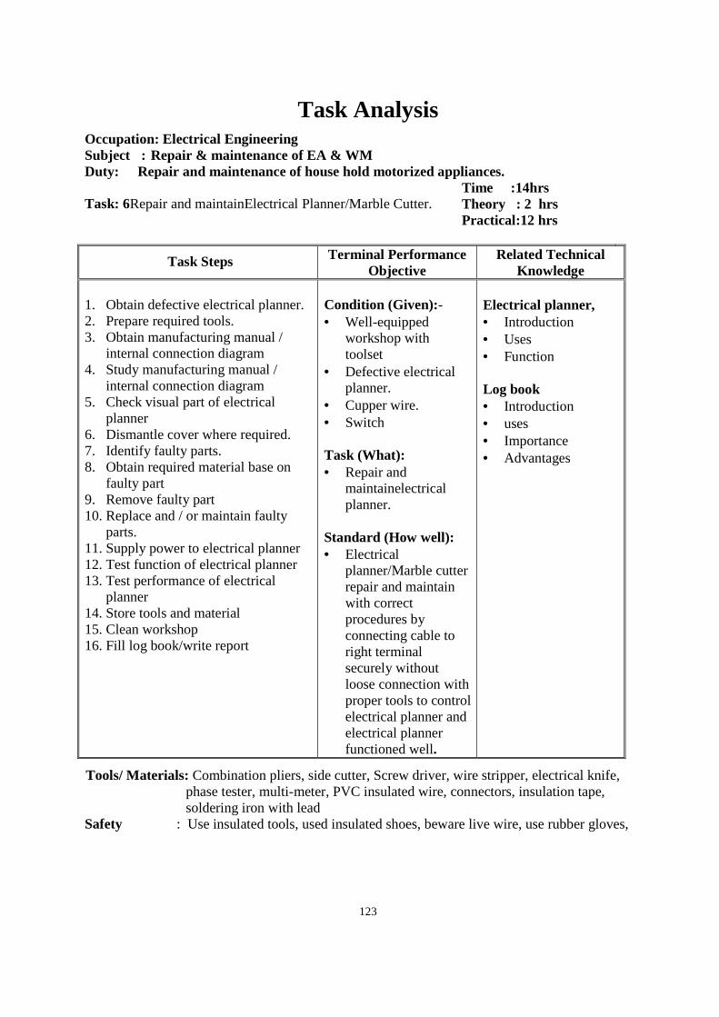
123
Task Analysis
Occupation: Electrical Engineering Subject : Repair & maintenance of EA & WM Duty: Repair and maintenance of house hold motorized appliances. Task: 6Repair and maintainElectrical Planner/Marble Cutter.
Time :14hrs Theory : 2 hrs Practical:12 hrs
Task Steps Terminal Performance Objective
Related Technical Knowledge
1. Obtain defective electrical planner. 2. Prepare required tools. 3. Obtain manufacturing manual /
internal connection diagram 4. Study manufacturing manual /
internal connection diagram 5. Check visual part of electrical
planner 6. Dismantle cover where required. 7. Identify faulty parts. 8. Obtain required material base on
faulty part 9. Remove faulty part 10. Replace and / or maintain faulty
parts. 11. Supply power to electrical planner 12. Test function of electrical planner 13. Test performance of electrical
planner 14. Store tools and material 15. Clean workshop 16. Fill log book/write report
Condition (Given):- • Well-equipped
workshop with toolset
• Defective electrical planner.
• Cupper wire. • Switch Task (What): • Repair and
maintainelectrical planner.
Standard (How well): • Electrical
planner/Marble cutter repair and maintain with correct procedures by connecting cable to right terminal securely without loose connection with proper tools to control electrical planner and electrical planner functioned well.
Electrical planner, • Introduction • Uses • Function Log book • Introduction • uses • Importance • Advantages
Tools/ Materials: Combination pliers, side cutter, Screw driver, wire stripper, electrical knife, phase tester, multi-meter, PVC insulated wire, connectors, insulation tape, soldering iron with lead
Safety : Use insulated tools, used insulated shoes, beware live wire, use rubber gloves,
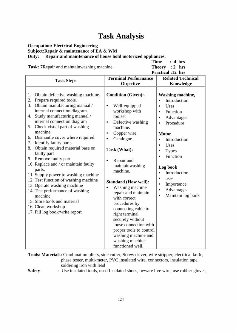
124
Task Analysis
Occupation: Electrical Engineering Subject:Repair & maintenance of EA & WM Duty: Repair and maintenance of house hold motorized appliances. Task: 7Repair and maintainwashing machine.
Time : 4 hrs Theory : 2 hrs Practical :12 hrs
Task Steps Terminal Performance Objective
Related Technical Knowledge
1. Obtain defective washing machine. 2. Prepare required tools. 3. Obtain manufacturing manual /
internal connection diagram 4. Study manufacturing manual /
internal connection diagram 5. Check visual part of washing
machine 6. Dismantle cover where required. 7. Identify faulty parts. 8. Obtain required material base on
faulty part 9. Remove faulty part 10. Replace and / or maintain faulty
parts. 11. Supply power to washing machine 12. Test function of washing machine 13. Operate washing machine 14. Test performance of washing
machine 15. Store tools and material 16. Clean workshop 17. Fill log book/write report
Condition (Given):- • Well-equipped
workshop with toolset
• Defective washing machine.
• Copper wire. • Catalogue Task (What): • Repair and
maintainwashing machine.
Standard (How well): • Washing machine
repair and maintain with correct procedures by connecting cable to right terminal securely without loose connection with proper tools to control washing machine and washing machine functioned well.
Washing machine, • Introduction • Uses • Function • Advantages • Procedure Motor • Introduction • Uses • Types • Function
Log book • Introduction • uses • Importance • Advantages • Maintain log book
Tools/ Materials: Combination pliers, side cutter, Screw driver, wire stripper, electrical knife, phase tester, multi-meter, PVC insulated wire, connectors, insulation tape, soldering iron with lead
Safety : Use insulated tools, used Insulated shoes, beware live wire, use rubber gloves,
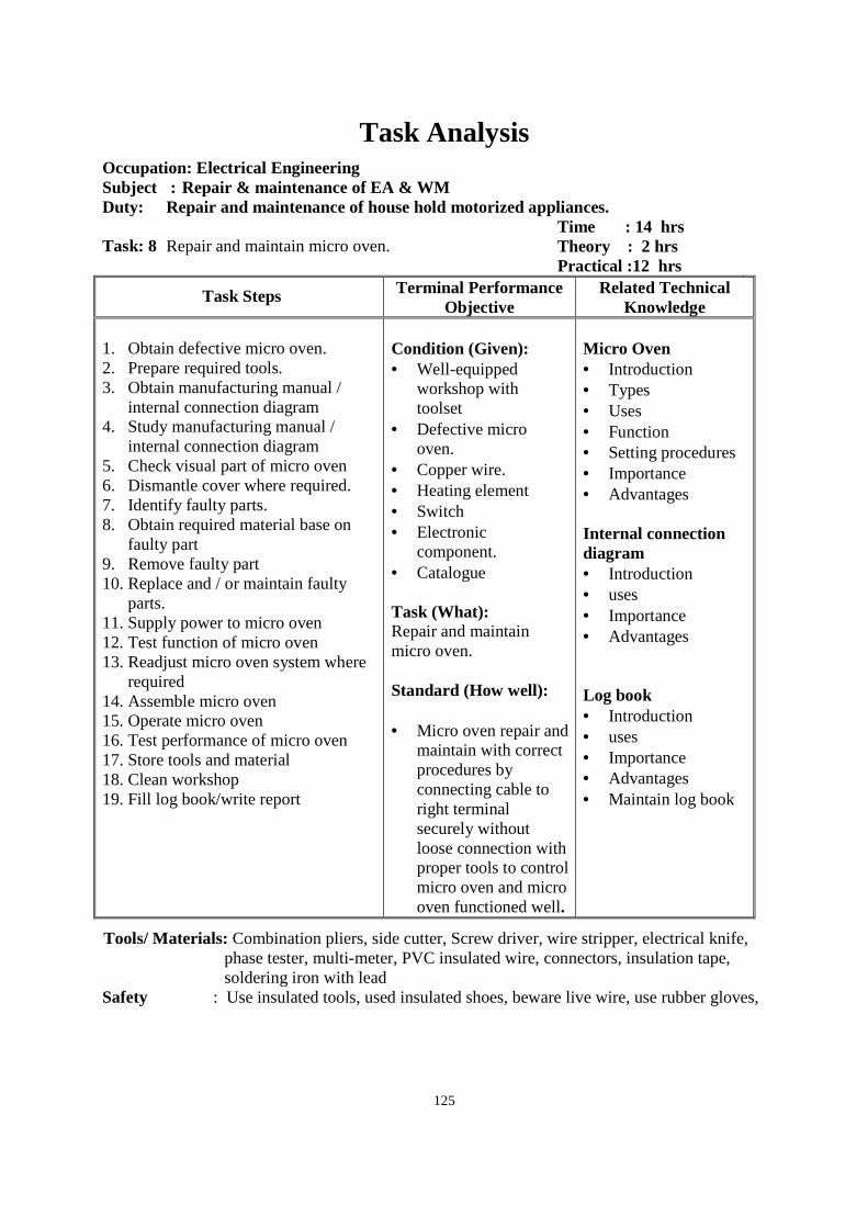
125
Task Analysis
Occupation: Electrical Engineering Subject : Repair & maintenance of EA & WM Duty: Repair and maintenance of house hold motorized appliances. Task: 8 Repair and maintain micro oven.
Time : 14 hrs Theory : 2 hrs Practical :12 hrs
Task Steps Terminal Performance Objective
Related Technical Knowledge
1. Obtain defective micro oven. 2. Prepare required tools. 3. Obtain manufacturing manual /
internal connection diagram 4. Study manufacturing manual /
internal connection diagram 5. Check visual part of micro oven 6. Dismantle cover where required. 7. Identify faulty parts. 8. Obtain required material base on
faulty part 9. Remove faulty part 10. Replace and / or maintain faulty
parts. 11. Supply power to micro oven 12. Test function of micro oven 13. Readjust micro oven system where
required 14. Assemble micro oven 15. Operate micro oven 16. Test performance of micro oven 17. Store tools and material 18. Clean workshop 19. Fill log book/write report
Condition (Given): • Well-equipped
workshop with toolset
• Defective micro oven.
• Copper wire. • Heating element • Switch • Electronic
component. • Catalogue Task (What): Repair and maintain micro oven. Standard (How well): • Micro oven repair and
maintain with correct procedures by connecting cable to right terminal securely without loose connection with proper tools to control micro oven and micro oven functioned well.
Micro Oven • Introduction • Types • Uses • Function • Setting procedures • Importance • Advantages Internal connection diagram • Introduction • uses • Importance • Advantages Log book • Introduction • uses • Importance • Advantages • Maintain log book
Tools/ Materials: Combination pliers, side cutter, Screw driver, wire stripper, electrical knife, phase tester, multi-meter, PVC insulated wire, connectors, insulation tape, soldering iron with lead
Safety : Use insulated tools, used insulated shoes, beware live wire, use rubber gloves,
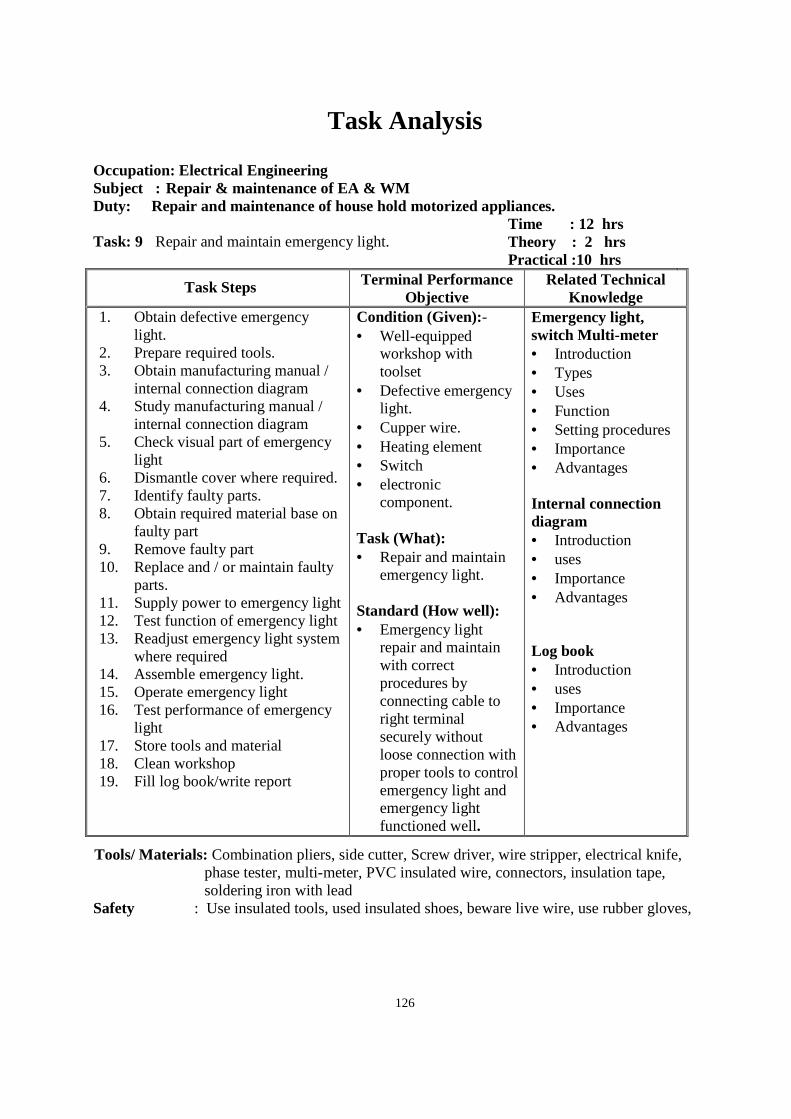
126
Task Analysis
Occupation: Electrical Engineering Subject : Repair & maintenance of EA & WM Duty: Repair and maintenance of house hold motorized appliances. Task: 9 Repair and maintain emergency light.
Time : 12 hrs Theory : 2 hrs Practical :10 hrs
Task Steps Terminal Performance Objective
Related Technical Knowledge
1. Obtain defective emergency light.
2. Prepare required tools. 3. Obtain manufacturing manual /
internal connection diagram 4. Study manufacturing manual /
internal connection diagram 5. Check visual part of emergency
light 6. Dismantle cover where required. 7. Identify faulty parts. 8. Obtain required material base on
faulty part 9. Remove faulty part 10. Replace and / or maintain faulty
parts. 11. Supply power to emergency light 12. Test function of emergency light 13. Readjust emergency light system
where required 14. Assemble emergency light. 15. Operate emergency light 16. Test performance of emergency
light 17. Store tools and material 18. Clean workshop 19. Fill log book/write report
Condition (Given):- • Well-equipped
workshop with toolset
• Defective emergency light.
• Cupper wire. • Heating element • Switch • electronic
component. Task (What): • Repair and maintain
emergency light. Standard (How well): • Emergency light
repair and maintain with correct procedures by connecting cable to right terminal securely without loose connection with proper tools to control emergency light and emergency light functioned well.
Emergency light, switch Multi-meter • Introduction • Types • Uses • Function • Setting procedures • Importance • Advantages Internal connection diagram • Introduction • uses • Importance • Advantages Log book • Introduction • uses • Importance • Advantages
Tools/ Materials: Combination pliers, side cutter, Screw driver, wire stripper, electrical knife, phase tester, multi-meter, PVC insulated wire, connectors, insulation tape, soldering iron with lead
Safety : Use insulated tools, used insulated shoes, beware live wire, use rubber gloves,
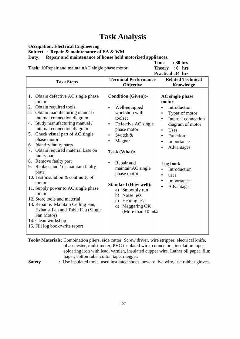
127
Task Analysis
Occupation: Electrical Engineering Subject : Repair & maintenance of EA & WM Duty: Repair and maintenance of house hold motorized appliances. Task: 10 Repair and maintainAC single phase motor.
Time : 30 hrs Theory : 6 hrs Practical :34 hrs
Task Steps Terminal Performance Objective
Related Technical Knowledge
1. Obtain defective AC single phase
motor. 2. Obtain required tools. 3. Obtain manufacturing manual /
internal connection diagram 4. Study manufacturing manual /
internal connection diagram 5. Check visual part of AC single
phase motor 6. Identify faulty parts. 7. Obtain required material base on
faulty part 8. Remove faulty part 9. Replace and / or maintain faulty
parts. 10. Test insulation & continuity of
motor 11. Supply power to AC single phase
motor 12. Store tools and material 13. Repair & Maintain Ceiling Fan,
Exhaust Fan and Table Fan (Single Fan Motor)
14. Clean workshop 15. Fill log book/write report
Condition (Given):- • Well-equipped
workshop with toolset
• Defective AC single phase motor.
• Switch & • Megger
Task (What): • Repair and
maintainAC single phase motor.
Standard (How well):
a) Smoothly run b) Noise less c) Heating less d) Meggaring OK
(More than 10 mΩ
AC single phase motor • Introduction • Types of motor • Internal connection
diagram of motor • Uses • Function • Importance • Advantages Log book • Introduction • uses • Importance • Advantages
Tools/ Materials: Combination pliers, side cutter, Screw driver, wire stripper, electrical knife, phase tester, multi-meter, PVC insulated wire, connectors, insulation tape, soldering iron with lead, varnish, insulated cupper wire. Lather oil paper, film paper, cotton tube, cotton tape, megger.
Safety : Use insulated tools, used insulated shoes, beware live wire, use rubber gloves,
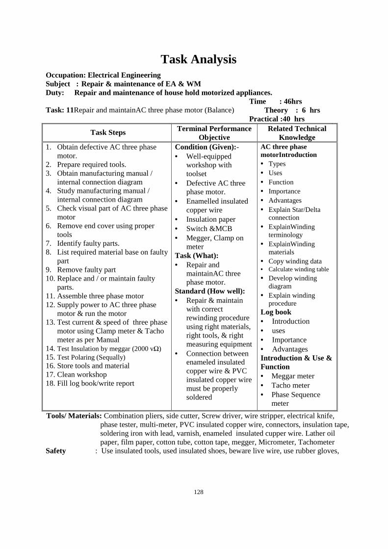
128
Task Analysis
Occupation: Electrical Engineering Subject : Repair & maintenance of EA & WM Duty: Repair and maintenance of house hold motorized appliances. Task: 11Repair and maintainAC three phase motor (Balance)
Time : 46hrs Theory : 6 hrs Practical :40 hrs
Task Steps Terminal Performance Objective
Related Technical Knowledge
1. Obtain defective AC three phase motor.
2. Prepare required tools. 3. Obtain manufacturing manual /
internal connection diagram 4. Study manufacturing manual /
internal connection diagram 5. Check visual part of AC three phase
motor 6. Remove end cover using proper
tools 7. Identify faulty parts. 8. List required material base on faulty
part 9. Remove faulty part 10. Replace and / or maintain faulty
parts. 11. Assemble three phase motor 12. Supply power to AC three phase
motor & run the motor 13. Test current & speed of three phase
motor using Clamp meter & Tacho meter as per Manual
14. Test Insulation by meggar (2000 vΩ) 15. Test Polaring (Sequally) 16. Store tools and material 17. Clean workshop 18. Fill log book/write report
Condition (Given):- • Well-equipped
workshop with toolset
• Defective AC three phase motor.
• Enamelled insulated copper wire
• Insulation paper • Switch &MCB • Megger, Clamp on
meter Task (What): • Repair and
maintainAC three phase motor.
Standard (How well): • Repair & maintain
with correct rewinding procedure using right materials, right tools, & right measuring equipment
• Connection between enameled insulated copper wire & PVC insulated copper wire must be properly soldered
AC three phase motorIntroduction • Types • Uses • Function • Importance • Advantages • Explain Star/Delta
connection • ExplainWinding
terminology • ExplainWinding
materials • Copy winding data • Calculate winding table
• Develop winding diagram
• Explain winding procedure
Log book • Introduction • uses • Importance • Advantages Introduction & Use & Function • Meggar meter • Tacho meter • Phase Sequence
meter
Tools/ Materials: Combination pliers, side cutter, Screw driver, wire stripper, electrical knife, phase tester, multi-meter, PVC insulated copper wire, connectors, insulation tape, soldering iron with lead, varnish, enameled insulated cupper wire. Lather oil paper, film paper, cotton tube, cotton tape, megger, Micrometer, Tachometer
Safety : Use insulated tools, used insulated shoes, beware live wire, use rubber gloves,
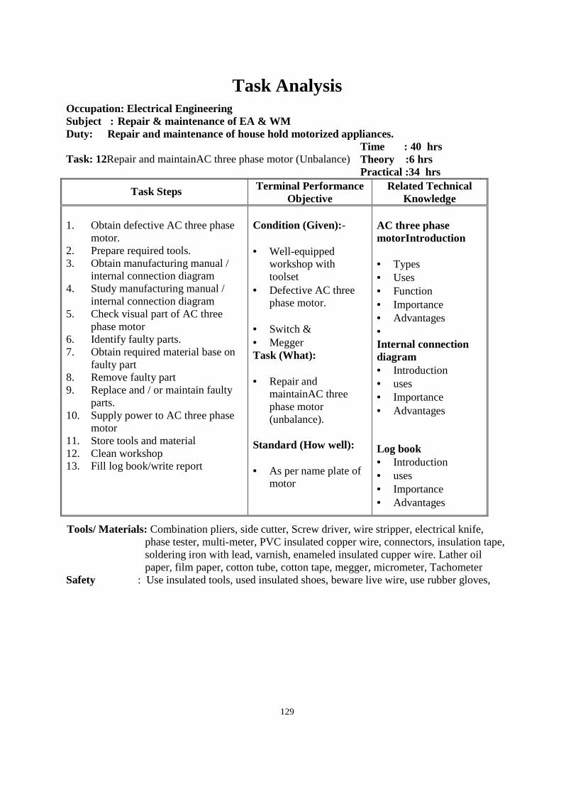
129
Task Analysis
Occupation: Electrical Engineering Subject : Repair & maintenance of EA & WM Duty: Repair and maintenance of house hold motorized appliances. Task: 12Repair and maintainAC three phase motor (Unbalance)
Time : 40 hrs Theory :6 hrs Practical :34 hrs
Task Steps Terminal Performance Objective
Related Technical Knowledge
1. Obtain defective AC three phase
motor. 2. Prepare required tools. 3. Obtain manufacturing manual /
internal connection diagram 4. Study manufacturing manual /
internal connection diagram 5. Check visual part of AC three
phase motor 6. Identify faulty parts. 7. Obtain required material base on
faulty part 8. Remove faulty part 9. Replace and / or maintain faulty
parts. 10. Supply power to AC three phase
motor 11. Store tools and material 12. Clean workshop 13. Fill log book/write report
Condition (Given):- • Well-equipped
workshop with toolset
• Defective AC three phase motor.
• Switch & • Megger Task (What): • Repair and
maintainAC three phase motor (unbalance).
Standard (How well): • As per name plate of
motor
AC three phase motorIntroduction • Types • Uses • Function • Importance • Advantages • Internal connection diagram • Introduction • uses • Importance • Advantages
Log book • Introduction • uses • Importance • Advantages
Tools/ Materials: Combination pliers, side cutter, Screw driver, wire stripper, electrical knife, phase tester, multi-meter, PVC insulated copper wire, connectors, insulation tape, soldering iron with lead, varnish, enameled insulated cupper wire. Lather oil paper, film paper, cotton tube, cotton tape, megger, micrometer, Tachometer
Safety : Use insulated tools, used insulated shoes, beware live wire, use rubber gloves,
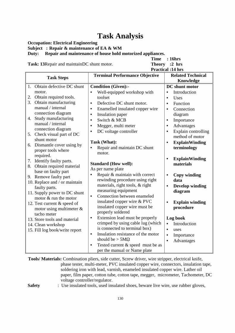
130
Task Analysis Occupation: Electrical Engineering Subject : Repair & maintenance of EA & WM Duty: Repair and maintenance of house hold motorized appliances. Task: 13Repair and maintainDC shunt motor.
Time : 16hrs Theory :2 hrs Practical :14 hrs
Task Steps Terminal Performance Objective Related Technical Knowledge
1. Obtain defective DC shunt motor.
2. Obtain required tools. 3. Obtain manufacturing
manual / internal connection diagram
4. Study manufacturing manual / internal connection diagram
5. Check visual part of DC shunt motor
6. Dismantle cover using by proper tools where required.
7. Identify faulty parts. 8. Obtain required material
base on faulty part 9. Remove faulty part 10. Replace and / or maintain
faulty parts. 11. Supply power to DC shunt
motor & run the motor 12. Test current & speed of
motor using multimeter & tacho meter
13. Store tools and material 14. Clean workshop 15. Fill log book/write report
Condition (Given):- • Well-equipped workshop with
toolset • Defective DC shunt motor. • Enamelled insulated copper wire • Insulation paper • Switch & MCB • Megger, multi meter • DC voltage controller Task (What): • Repair and maintain DC shunt
motor. Standard (How well): As per name plate • Repair & maintain with correct
rewinding procedure using right materials, right tools, & right measuring equipment
• Connection between enameled insulated copper wire & PVC insulated copper wire must be properly soldered
• Extension lead must be properly crimped by using cable lug (which is connected to terminal box)
• Insulation resistance of the motor should be > 5Mῼ
• Tested current & speed must be as per the manual or Name plate
DC shunt motor • Introduction • Uses • Function • Connection
diagram • Importance • Advantages • Explain controlling
method of motor • ExplainWinding
terminology
• ExplainWinding materials
• Copy winding
data • Develop winding
diagram
• Explain winding procedure
Log book • Introduction • uses • Importance • Advantages
Tools/ Materials: Combination pliers, side cutter, Screw driver, wire stripper, electrical knife, phase tester, multi-meter, PVC insulated copper wire, connectors, insulation tape, soldering iron with lead, varnish, enameled insulated copper wire. Lather oil paper, film paper, cotton tube, cotton tape, megger, micrometer, Tachometer, DC voltage controller/regulator.
Safety : Use insulated tools, used insulated shoes, beware live wire, use rubber gloves,
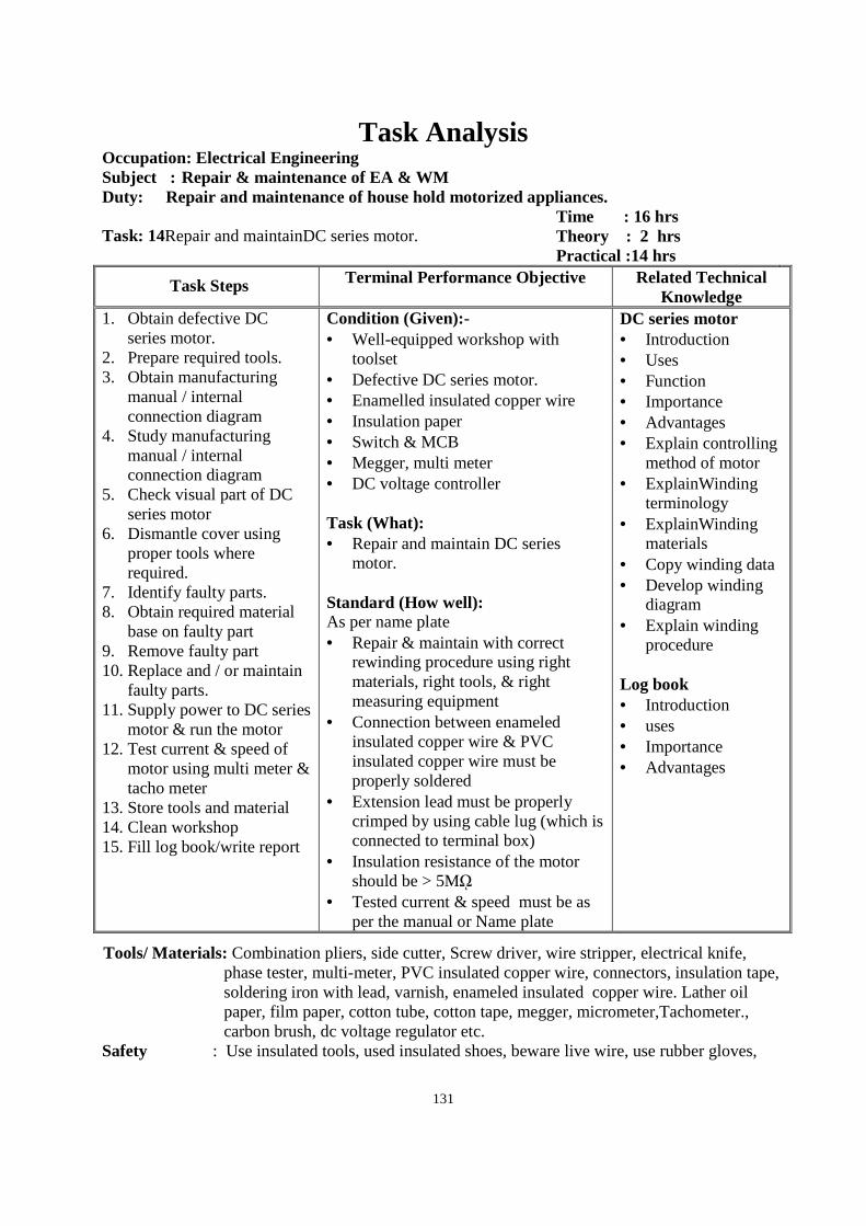
131
Task Analysis Occupation: Electrical Engineering Subject : Repair & maintenance of EA & WM Duty: Repair and maintenance of house hold motorized appliances. Task: 14Repair and maintainDC series motor.
Time : 16 hrs Theory : 2 hrs Practical :14 hrs
Task Steps Terminal Performance Objective Related Technical Knowledge
1. Obtain defective DC series motor.
2. Prepare required tools. 3. Obtain manufacturing
manual / internal connection diagram
4. Study manufacturing manual / internal connection diagram
5. Check visual part of DC series motor
6. Dismantle cover using proper tools where required.
7. Identify faulty parts. 8. Obtain required material
base on faulty part 9. Remove faulty part 10. Replace and / or maintain
faulty parts. 11. Supply power to DC series
motor & run the motor 12. Test current & speed of
motor using multi meter & tacho meter
13. Store tools and material 14. Clean workshop 15. Fill log book/write report
Condition (Given):- • Well-equipped workshop with
toolset • Defective DC series motor. • Enamelled insulated copper wire • Insulation paper • Switch & MCB • Megger, multi meter • DC voltage controller Task (What): • Repair and maintain DC series
motor. Standard (How well): As per name plate • Repair & maintain with correct
rewinding procedure using right materials, right tools, & right measuring equipment
• Connection between enameled insulated copper wire & PVC insulated copper wire must be properly soldered
• Extension lead must be properly crimped by using cable lug (which is connected to terminal box)
• Insulation resistance of the motor should be > 5Mῼ
• Tested current & speed must be as per the manual or Name plate
DC series motor • Introduction • Uses • Function • Importance • Advantages • Explain controlling
method of motor • ExplainWinding
terminology • ExplainWinding
materials • Copy winding data • Develop winding
diagram • Explain winding
procedure
Log book • Introduction • uses • Importance • Advantages
Tools/ Materials: Combination pliers, side cutter, Screw driver, wire stripper, electrical knife, phase tester, multi-meter, PVC insulated copper wire, connectors, insulation tape, soldering iron with lead, varnish, enameled insulated copper wire. Lather oil paper, film paper, cotton tube, cotton tape, megger, micrometer,Tachometer., carbon brush, dc voltage regulator etc.
Safety : Use insulated tools, used insulated shoes, beware live wire, use rubber gloves,
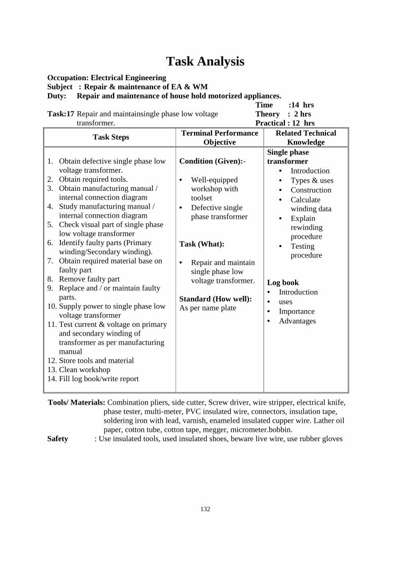
132
Task Analysis
Occupation: Electrical Engineering Subject : Repair & maintenance of EA & WM Duty: Repair and maintenance of house hold motorized appliances. Task:17 Repair and maintainsingle phase low voltage
transformer.
Time :14 hrs Theory : 2 hrs Practical : 12 hrs
Task Steps Terminal Performance Objective
Related Technical Knowledge
1. Obtain defective single phase low
voltage transformer. 2. Obtain required tools. 3. Obtain manufacturing manual /
internal connection diagram 4. Study manufacturing manual /
internal connection diagram 5. Check visual part of single phase
low voltage transformer 6. Identify faulty parts (Primary
winding/Secondary winding). 7. Obtain required material base on
faulty part 8. Remove faulty part 9. Replace and / or maintain faulty
parts. 10. Supply power to single phase low
voltage transformer 11. Test current & voltage on primary
and secondary winding of transformer as per manufacturing manual
12. Store tools and material 13. Clean workshop 14. Fill log book/write report
Condition (Given):- • Well-equipped
workshop with toolset
• Defective single phase transformer
Task (What): • Repair and maintain
single phase low voltage transformer.
Standard (How well): As per name plate
Single phase transformer
• Introduction • Types & uses • Construction • Calculate
winding data • Explain
rewinding procedure
• Testing procedure
Log book • Introduction • uses • Importance • Advantages
Tools/ Materials: Combination pliers, side cutter, Screw driver, wire stripper, electrical knife, phase tester, multi-meter, PVC insulated wire, connectors, insulation tape, soldering iron with lead, varnish, enameled insulated cupper wire. Lather oil paper, cotton tube, cotton tape, megger, micrometer.bobbin.
Safety : Use insulated tools, used insulated shoes, beware live wire, use rubber gloves
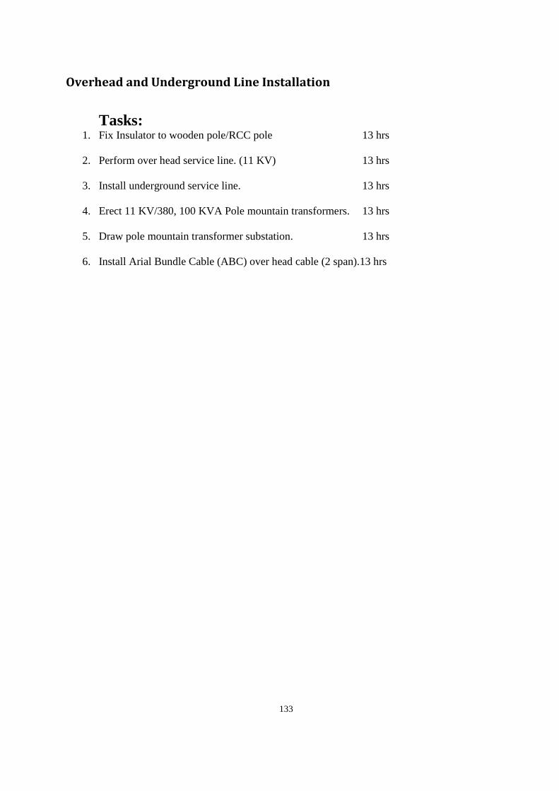
133
Overhead and Underground Line Installation
Tasks:
1. Fix Insulator to wooden pole/RCC pole 13 hrs
2. Perform over head service line. (11 KV) 13 hrs
3. Install underground service line. 13 hrs
4. Erect 11 KV/380, 100 KVA Pole mountain transformers. 13 hrs
5. Draw pole mountain transformer substation. 13 hrs
6. Install Arial Bundle Cable (ABC) over head cable (2 span).13 hrs
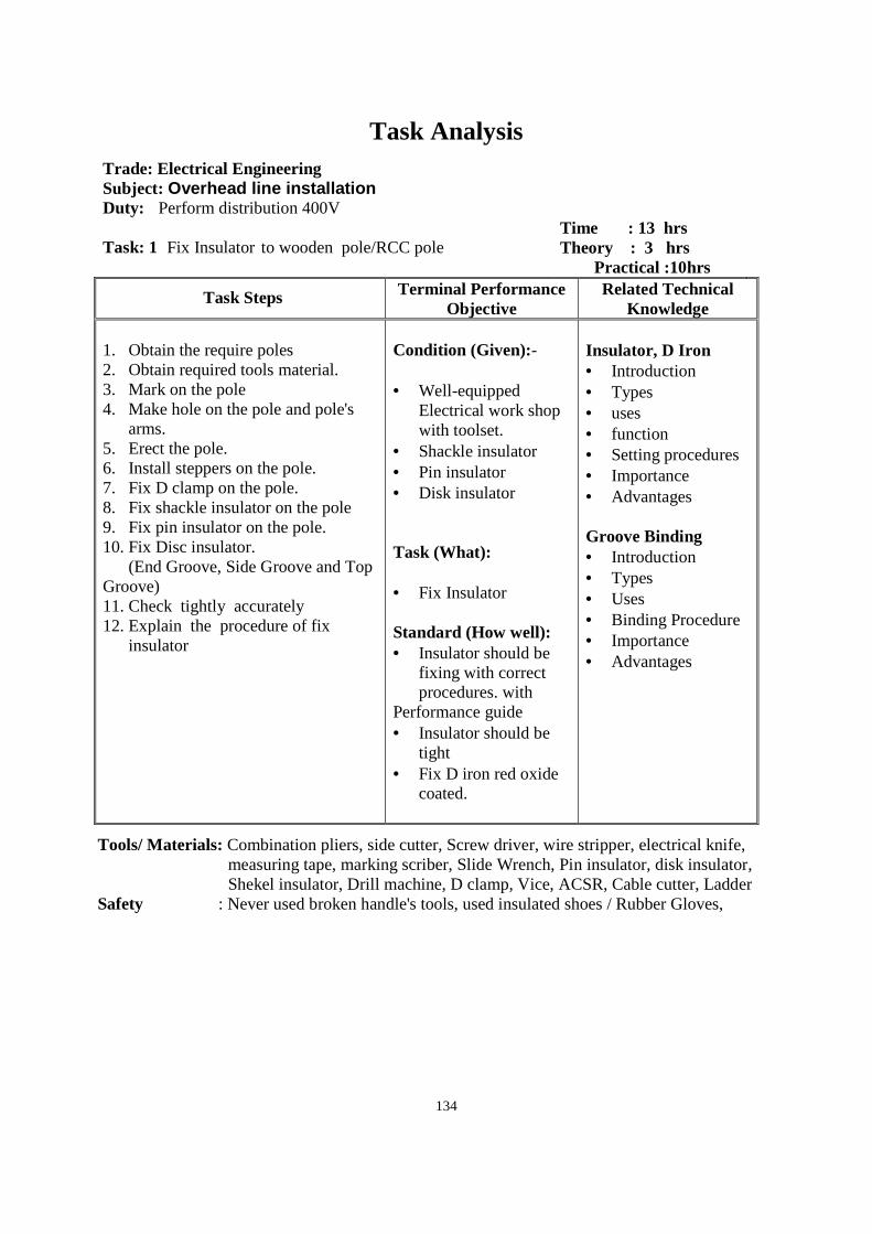
134
Task Analysis
Trade: Electrical Engineering Subject: Overhead line installation Duty: Perform distribution 400V Task: 1 Fix Insulator to wooden pole/RCC pole
Time : 13 hrs Theory : 3 hrs Practical :10hrs
Task Steps Terminal Performance Objective
Related Technical Knowledge
1. Obtain the require poles 2. Obtain required tools material. 3. Mark on the pole 4. Make hole on the pole and pole's
arms. 5. Erect the pole. 6. Install steppers on the pole. 7. Fix D clamp on the pole. 8. Fix shackle insulator on the pole 9. Fix pin insulator on the pole. 10. Fix Disc insulator. (End Groove, Side Groove and Top Groove) 11. Check tightly accurately 12. Explain the procedure of fix
insulator
Condition (Given):- • Well-equipped
Electrical work shop with toolset.
• Shackle insulator • Pin insulator • Disk insulator Task (What): • Fix Insulator Standard (How well): • Insulator should be
fixing with correct procedures. with
Performance guide • Insulator should be
tight • Fix D iron red oxide
coated.
Insulator, D Iron • Introduction • Types • uses • function • Setting procedures • Importance • Advantages Groove Binding • Introduction • Types • Uses • Binding Procedure • Importance • Advantages
Tools/ Materials: Combination pliers, side cutter, Screw driver, wire stripper, electrical knife, measuring tape, marking scriber, Slide Wrench, Pin insulator, disk insulator, Shekel insulator, Drill machine, D clamp, Vice, ACSR, Cable cutter, Ladder
Safety : Never used broken handle's tools, used insulated shoes / Rubber Gloves,
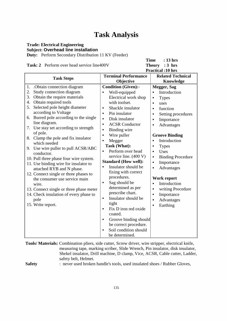
135
Task Analysis
Trade: Electrical Engineering Subject: Overhead line installation Duty: Perform Secondary Distribution 11 KV (Feeder) Task: 2 Perform over head service line400V
Time : 13 hrs Theory : 3 hrs Practical :10 hrs
Task Steps Terminal Performance Objective
Related Technical Knowledge
1. .Obtain connection diagram 2. Study connection diagram 3. Obtain the require materials 4. Obtain required tools 5. Selected pole height diameter
according to Voltage 6. Burred pole according to the single
line diagram. 7. Use stay set according to strength
of pole. 8. Clamp the pole and fix insulator
which needed 9. Use wire puller to pull ACSR/ABC
conductor. 10. Pull three phase four wire system. 11. Use binding wire for insulator to
attached RYB and N phase. 12. Connect single or three phases to
the consumer use service main wire.
13. Connect single or three phase meter 14. Check insulation of every phase to
pole 15. Write report.
Condition (Given):- • Well-equipped
Electrical work shop with toolset.
• Shackle insulator • Pin insulator • Disk insulator • ACSR Conductor • Binding wire • Wire puller • Megger
Task (What): • Perform over head
service line. (400 V) Standard (How well): • Insulator should be
fixing with correct procedures.
• Sag should be determined as per prescribe chart.
• Insulator should be tight
• Fix D iron red oxide coated.
• Groove binding should be correct procedure.
• Soil condition should be determined.
Megger, Sag • Introduction • Types • uses • function • Setting procedures • Importance • Advantages Groove Binding • Introduction • Types • Uses • Binding Procedure • Importance • Advantages Work report • Introduction • writing Procedure • Importance • Advantages • Earthing
Tools/ Materials: Combination pliers, side cutter, Screw driver, wire stripper, electrical knife, measuring tape, marking scriber, Slide Wrench, Pin insulator, disk insulator, Shekel insulator, Drill machine, D clamp, Vice, ACSR, Cable cutter, Ladder, safety belt, Helmet.
Safety : never used broken handle's tools, used insulated shoes / Rubber Gloves,
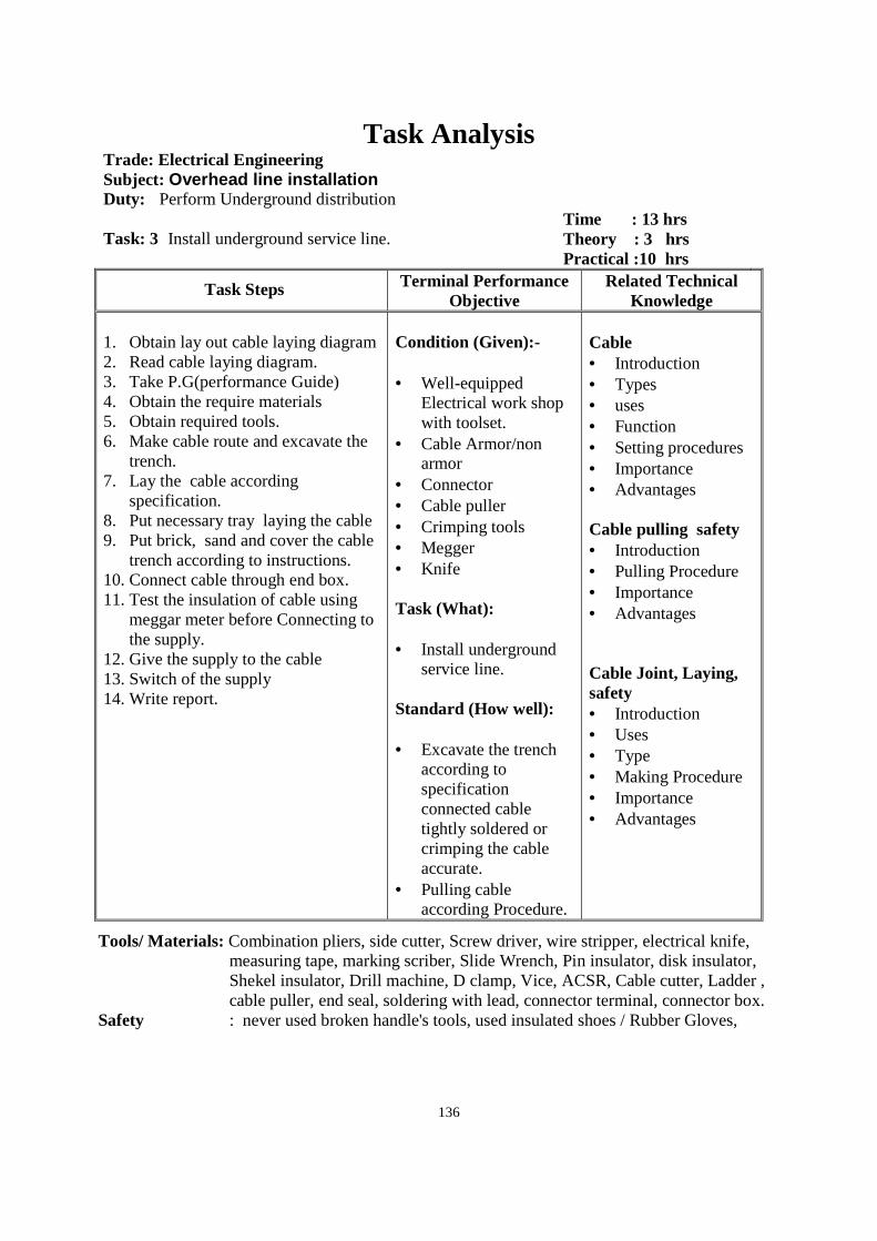
136
Task Analysis Trade: Electrical Engineering Subject: Overhead line installation Duty: Perform Underground distribution Task: 3 Install underground service line.
Time : 13 hrs Theory : 3 hrs Practical :10 hrs
Task Steps Terminal Performance Objective
Related Technical Knowledge
1. Obtain lay out cable laying diagram 2. Read cable laying diagram. 3. Take P.G(performance Guide) 4. Obtain the require materials 5. Obtain required tools. 6. Make cable route and excavate the
trench. 7. Lay the cable according
specification. 8. Put necessary tray laying the cable 9. Put brick, sand and cover the cable
trench according to instructions. 10. Connect cable through end box. 11. Test the insulation of cable using
meggar meter before Connecting to the supply.
12. Give the supply to the cable 13. Switch of the supply 14. Write report.
Condition (Given):- • Well-equipped
Electrical work shop with toolset.
• Cable Armor/non armor
• Connector • Cable puller • Crimping tools • Megger • Knife Task (What): • Install underground
service line. Standard (How well): • Excavate the trench
according to specification connected cable tightly soldered or crimping the cable accurate.
• Pulling cable according Procedure.
Cable • Introduction • Types • uses • Function • Setting procedures • Importance • Advantages Cable pulling safety • Introduction • Pulling Procedure • Importance • Advantages Cable Joint, Laying, safety • Introduction • Uses • Type • Making Procedure • Importance • Advantages
Tools/ Materials: Combination pliers, side cutter, Screw driver, wire stripper, electrical knife, measuring tape, marking scriber, Slide Wrench, Pin insulator, disk insulator, Shekel insulator, Drill machine, D clamp, Vice, ACSR, Cable cutter, Ladder , cable puller, end seal, soldering with lead, connector terminal, connector box.
Safety : never used broken handle's tools, used insulated shoes / Rubber Gloves,

137
Task Analysis
Trade: Electrical Engineering Subject: Overhead line installation Duty: Perform Distribution supply system Task: 4 Erect Pole mounted substation (Transformers)
Time : 13 hrs Theory : 3 hrs Practical :10 hrs
Task Steps Terminal Performance Objective
Related Technical Knowledge
1. Obtain lay out and connection
diagram of Pole mounted substation 2. Read lay out and connection
diagram 3. Listout the tools and materials 4. Obtain the require tool & materials 5. Take P,G(Performance guide) for
connection electrical fitting. 6. Connect the three phase supply
system LT & HT. 7. Take three phase Low voltage
busing connect by PG clamp 8. Check the Earthing on the body of
transformer 9. Test and commissioning insulation
by megger (R-Y.R-B,B-Y and RYB-body of transformer.
10. Connect main supply 11. Cut supply 12. Collect the tools and materials. 13. Write report
Condition (Given):- • Well-equipped
toolset. • Place of erect
transformer • DO Fuse • Isolator • PG clamp • Pin insulator • Shackle insulator Task (What): Erect Pole mounted substation ( transformers.) Standard (How well): • DO Fuse, Isolator
should be connect tightly
• PG clamp should be connect tightly
Insulator, D Iron • Introduction • Types • uses • function • Setting procedures • Importance • Advantages Groove Binding • Introduction • Types • Uses • Binding Procedure • Importance • Advantages
Tools/ Materials: Combination pliers, side cutter, Screw driver, wire stripper, electrical knife, measuring tape, marking scriber, Slide Wrench, PG clamp, Cable, Earth tester, Megger, Lead. DO Fuse, Drill machine, D clamp, Vice, ACSR, Cable cutter, Ladder
Safety : never used broken handle's tools, used insulated shoes / Rubber Gloves,
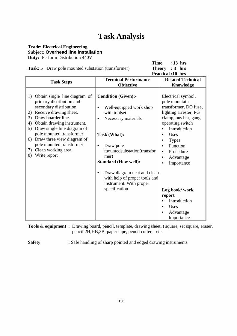
138
Task Analysis
Trade: Electrical Engineering Subject: Overhead line installation Duty: Perform Distribution 440V Task: 5 Draw pole mounted substation (transformer)
Time : 13 hrs Theory : 3 hrs Practical :10 hrs
Task Steps Terminal Performance Objective
Related Technical Knowledge
1) Obtain single line diagram of
primary distribution and secondary distribution
2) Receive drawing sheet. 3) Draw boarder line. 4) Obtain drawing instrument. 5) Draw single line diagram of
pole mounted transformer 6) Draw three view diagram of
pole mounted transformer 7) Clean working area. 8) Write report
Condition (Given):- • Well-equipped work shop
with toolset. • Necessary materials Task (What): • Draw pole
mountedsubstation(transformer)
Standard (How well): • Draw diagram neat and clean
with help of proper tools and instrument. With proper specification.
Electrical symbol, pole mountain transformer, DO fuse, lighting arrester, PG clamp, bus bar, gang operating switch • Introduction • Uses • Types • Function • Procedure • Advantage • Importance Log book/ work report • Introduction • Uses • Advantage
Importance
Tools & equipment : Drawing board, pencil, template, drawing sheet, t square, set square, eraser, pencil 2H,HB,2B, paper tape, pencil cutter, etc.
Safety : Safe handling of sharp pointed and edged drawing instruments
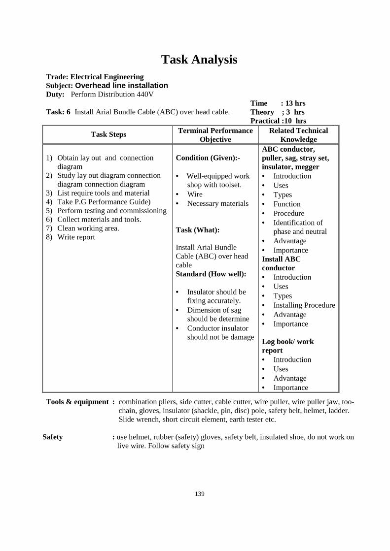
139
Task Analysis
Trade: Electrical Engineering Subject: Overhead line installation Duty: Perform Distribution 440V Task: 6 Install Arial Bundle Cable (ABC) over head cable.
Time : 13 hrs Theory ; 3 hrs Practical :10 hrs
Task Steps Terminal Performance Objective
Related Technical Knowledge
1) Obtain lay out and connection
diagram 2) Study lay out diagram connection
diagram connection diagram 3) List require tools and material 4) Take P.G Performance Guide) 5) Perform testing and commissioning 6) Collect materials and tools. 7) Clean working area. 8) Write report
Condition (Given):- • Well-equipped work
shop with toolset. • Wire • Necessary materials Task (What): Install Arial Bundle Cable (ABC) over head cable Standard (How well): • Insulator should be
fixing accurately. • Dimension of sag
should be determine • Conductor insulator
should not be damage
ABC conductor, puller, sag, stray set, insulator, megger • Introduction • Uses • Types • Function • Procedure • Identification of
phase and neutral • Advantage • Importance Install ABC conductor • Introduction • Uses • Types • Installing Procedure • Advantage • Importance Log book/ work report • Introduction • Uses • Advantage • Importance
Tools & equipment : combination pliers, side cutter, cable cutter, wire puller, wire puller jaw, too-chain, gloves, insulator (shackle, pin, disc) pole, safety belt, helmet, ladder. Slide wrench, short circuit element, earth tester etc.
Safety : use helmet, rubber (safety) gloves, safety belt, insulated shoe, do not work on
live wire. Follow safety sign
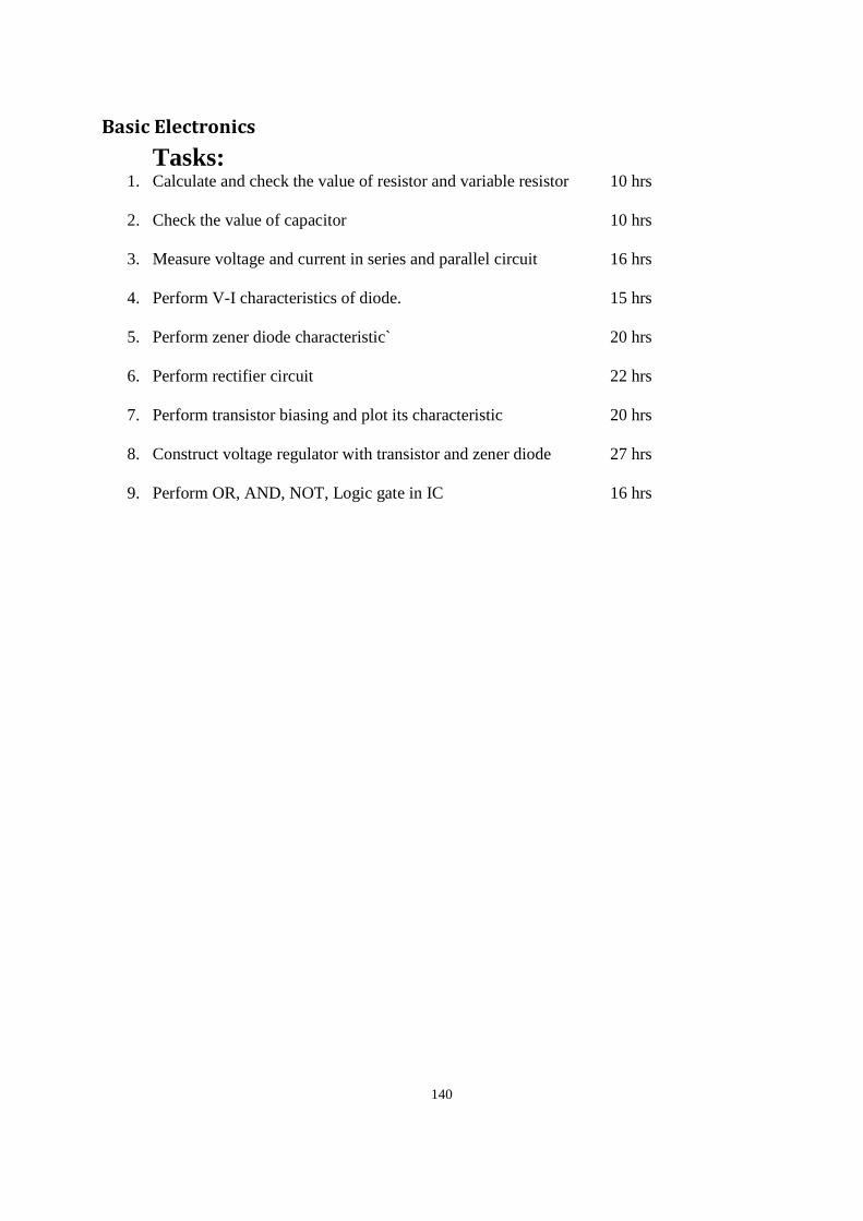
140
Basic Electronics Tasks:
1. Calculate and check the value of resistor and variable resistor 10 hrs
2. Check the value of capacitor 10 hrs
3. Measure voltage and current in series and parallel circuit 16 hrs
4. Perform V-I characteristics of diode. 15 hrs
5. Perform zener diode characteristic` 20 hrs
6. Perform rectifier circuit 22 hrs
7. Perform transistor biasing and plot its characteristic 20 hrs
8. Construct voltage regulator with transistor and zener diode 27 hrs
9. Perform OR, AND, NOT, Logic gate in IC 16 hrs
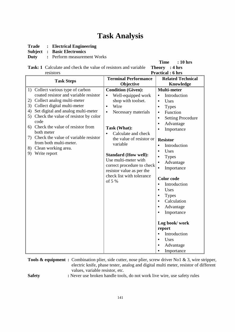
141
Task Analysis
Trade : Electrical Engineering Subject : Basic Electronics Duty : Perform measurement Works Task: 1 Calculate and check the value of resistors and variable
resistors
Time : 10 hrs Theory : 4 hrs Practical : 6 hrs
Task Steps Terminal Performance Objective
Related Technical Knowledge
1) Collect various type of carbon coated resistor and variable resistor
2) Collect analog multi-meter 3) Collect digital multi-meter 4) Set digital and analog multi-meter 5) Check the value of resistor by color
code 6) Check the value of resistor from
both meter 7) Check the value of variable resistor
from both multi-meter. 8) Clean working area. 9) Write report
Condition (Given): • Well-equipped work
shop with toolset. • Wire • Necessary materials Task (What): • Calculate and check
the value of resistor or variable
Standard (How well): Use multi-meter with correct procedure to check resistor value as per the check list with tolerance of 5 %
Multi-meter • Introduction • Uses • Types • Function • Setting Procedure • Advantage • Importance Resistor • Introduction • Uses • Types • Advantage • Importance Color code • Introduction • Uses • Types • Calculation • Advantage • Importance Log book/ work report • Introduction • Uses • Advantage • Importance
Tools & equipment : Combination plier, side cutter, nose plier, screw driver No1 & 3, wire stripper, electric knife, phase tester, analog and digital multi meter, resistor of different values, variable resistor, etc.
Safety : Never use broken handle tools, do not work live wire, use safety rules
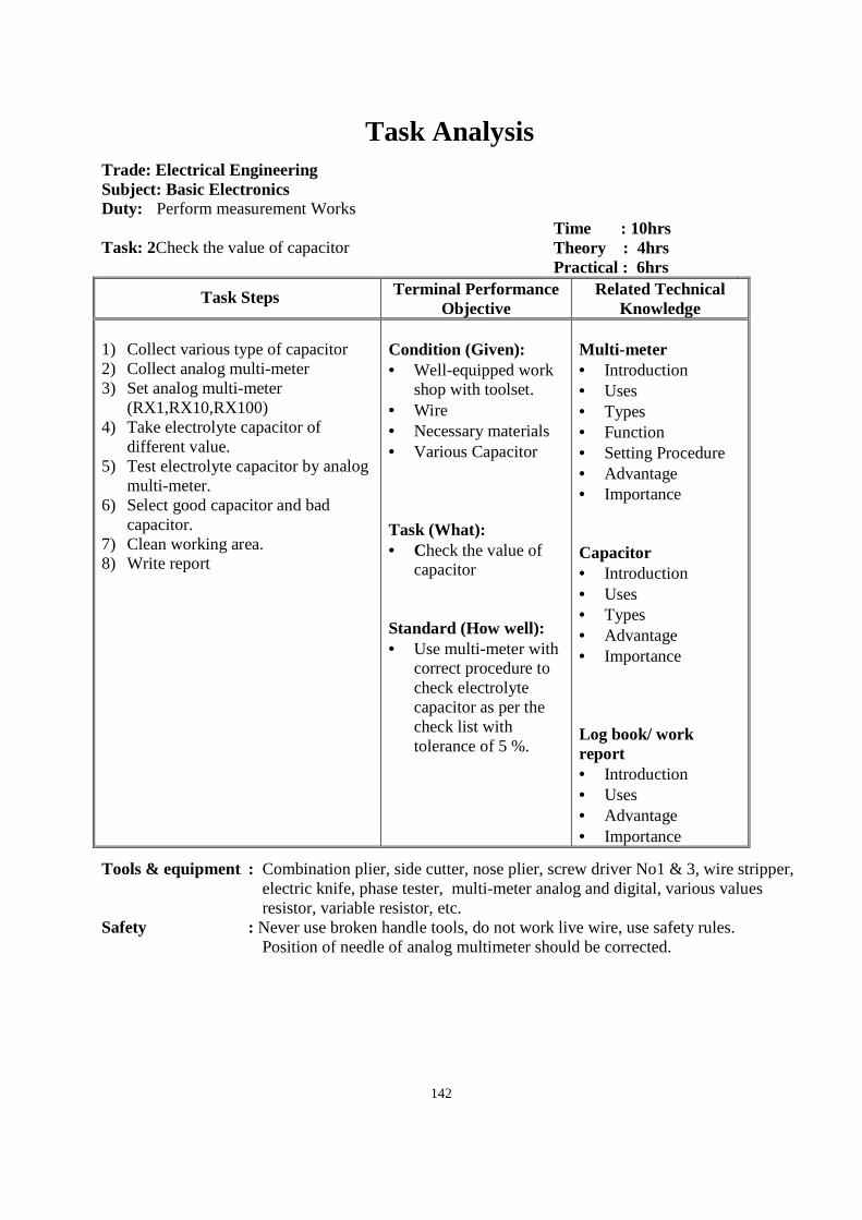
142
Task Analysis
Trade: Electrical Engineering Subject: Basic Electronics Duty: Perform measurement Works Task: 2Check the value of capacitor
Time : 10hrs Theory : 4hrs Practical : 6hrs
Task Steps Terminal Performance Objective
Related Technical Knowledge
1) Collect various type of capacitor 2) Collect analog multi-meter 3) Set analog multi-meter
(RX1,RX10,RX100) 4) Take electrolyte capacitor of
different value. 5) Test electrolyte capacitor by analog
multi-meter. 6) Select good capacitor and bad
capacitor. 7) Clean working area. 8) Write report
Condition (Given): • Well-equipped work
shop with toolset. • Wire • Necessary materials • Various Capacitor Task (What): • Check the value of
capacitor Standard (How well): • Use multi-meter with
correct procedure to check electrolyte capacitor as per the check list with tolerance of 5 %.
Multi-meter • Introduction • Uses • Types • Function • Setting Procedure • Advantage • Importance Capacitor • Introduction • Uses • Types • Advantage • Importance Log book/ work report • Introduction • Uses • Advantage • Importance
Tools & equipment : Combination plier, side cutter, nose plier, screw driver No1 & 3, wire stripper, electric knife, phase tester, multi-meter analog and digital, various values resistor, variable resistor, etc.
Safety : Never use broken handle tools, do not work live wire, use safety rules. Position of needle of analog multimeter should be corrected.
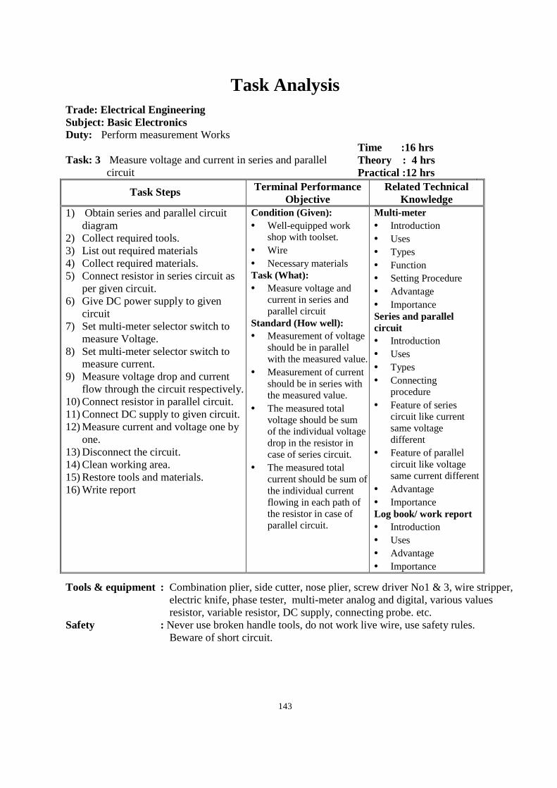
143
Task Analysis
Trade: Electrical Engineering Subject: Basic Electronics Duty: Perform measurement Works Task: 3 Measure voltage and current in series and parallel
circuit
Time :16 hrs Theory : 4 hrs Practical :12 hrs
Task Steps Terminal Performance Objective
Related Technical Knowledge
1) Obtain series and parallel circuit diagram
2) Collect required tools. 3) List out required materials 4) Collect required materials. 5) Connect resistor in series circuit as
per given circuit. 6) Give DC power supply to given
circuit 7) Set multi-meter selector switch to
measure Voltage. 8) Set multi-meter selector switch to
measure current. 9) Measure voltage drop and current
flow through the circuit respectively. 10) Connect resistor in parallel circuit. 11) Connect DC supply to given circuit. 12) Measure current and voltage one by
one. 13) Disconnect the circuit. 14) Clean working area. 15) Restore tools and materials. 16) Write report
Condition (Given): • Well-equipped work
shop with toolset. • Wire • Necessary materials Task (What): • Measure voltage and
current in series and parallel circuit
Standard (How well): • Measurement of voltage
should be in parallel with the measured value.
• Measurement of current should be in series with the measured value.
• The measured total voltage should be sum of the individual voltage drop in the resistor in case of series circuit.
• The measured total current should be sum of the individual current flowing in each path of the resistor in case of parallel circuit.
Multi -meter • Introduction • Uses • Types • Function • Setting Procedure • Advantage • Importance Series and parallel circuit • Introduction • Uses • Types • Connecting
procedure • Feature of series
circuit like current same voltage different
• Feature of parallel circuit like voltage same current different
• Advantage • Importance Log book/ work report • Introduction • Uses • Advantage • Importance
Tools & equipment : Combination plier, side cutter, nose plier, screw driver No1 & 3, wire stripper, electric knife, phase tester, multi-meter analog and digital, various values resistor, variable resistor, DC supply, connecting probe. etc.
Safety : Never use broken handle tools, do not work live wire, use safety rules. Beware of short circuit.
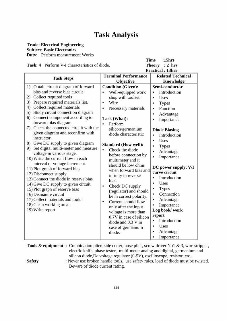
144
Task Analysis
Trade: Electrical Engineering Subject: Basic Electronics Duty: Perform measurement Works Task: 4 Perform V-I characteristics of diode.
Time :15hrs Theory : 2 hrs Practical : 13hrs
Task Steps Terminal Performance Objective
Related Technical Knowledge
1) Obtain circuit diagram of forward bias and reverse bias circuit
2) Collect required tools 3) Prepare required materials list. 4) Collect required materials 5) Study circuit connection diagram 6) Connect component according to
forward bias diagram 7) Check the connected circuit with the
given diagram and reconfirm with instructor.
8) Give DC supply to given diagram 9) Set digital multi-meter and measure
voltage in various stage. 10) Write the current flow in each
interval of voltage increment. 11) Plot graph of forward bias 12) Disconnect supply. 13) Connect the diode in reserve bias 14) Give DC supply to given circuit. 15) Plot graph of reserve bias 16) Dismantle circuit 17) Collect materials and tools 18) Clean working area. 19) Write report
Condition (Given): • Well-equipped work
shop with toolset. • Wire • Necessary materials Task (What): • Perform
silicon/germanium diode characteristic
Standard (How well): • Check the diode
before connection by multimeter and it should be low ohms when forward bias and infinity in reverse bias.
• Check DC supply (regulator) and should be in correct polarity.
• Current should flow only after the input voltage is more than 0.7V in case of silicon diode and 0.3 V in case of germanium diode.
Semi-conductor • Introduction • Uses • Types • Function • Advantage • Importance Diode Biasing • Introduction • Uses • Types • Advantage • Importance DC power supply, V/I curve circuit • Introduction • Uses • Types • Connection • Advantage • Importance Log book/ work report • Introduction • Uses • Advantage • Importance
Tools & equipment : Combination plier, side cutter, nose plier, screw driver No1 & 3, wire stripper, electric knife, phase tester, multi-meter analog and digital, germanium and silicon diode,Dc voltage regulator (0-5V), oscilloscope, resistor, etc.
Safety : Never use broken handle tools, use safety rules, load of diode must be twisted. Beware of diode current rating.
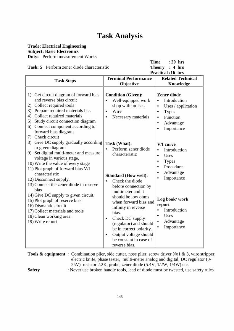
145
Task Analysis
Trade: Electrical Engineering Subject: Basic Electronics Duty: Perform measurement Works Task: 5 Perform zener diode characteristic
Time : 20 hrs Theory : 4 hrs Practical :16 hrs
Task Steps Terminal Performance Objective
Related Technical Knowledge
1) Get circuit diagram of forward bias
and reverse bias circuit 2) Collect required tools 3) Prepare required materials list. 4) Collect required materials 5) Study circuit connection diagram 6) Connect component according to
forward bias diagram 7) Check circuit 8) Give DC supply gradually according
to given diagram 9) Set digital multi-meter and measure
voltage in various stage. 10) Write the value of every stage 11) Plot graph of forward bias V/I
characteristic 12) Disconnect supply. 13) Connect the zener diode in reserve
bias 14) Give DC supply to given circuit. 15) Plot graph of reserve bias 16) Dismantle circuit 17) Collect materials and tools 18) Clean working area. 19) Write report
Condition (Given): • Well-equipped work
shop with toolset. • Wire • Necessary materials Task (What): • Perform zener diode
characteristic Standard (How well): • Check the diode
before connection by multimeter and it should be low ohms when forward bias and infinity in reverse bias.
• Check DC supply (regulator) and should be in correct polarity.
• Output voltage should be constant in case of reverse bias.
Zener diode • Introduction • Uses / application • Types • Function • Advantage • Importance V/I curve • Introduction • Uses • Types • Procedure • Advantage • Importance Log book/ work report • Introduction • Uses • Advantage • Importance
Tools & equipment : Combination plier, side cutter, nose plier, screw driver No1 & 3, wire stripper, electric knife, phase tester, multi-meter analog and digital, DC regulator (0-25V) resistor 2.2K, probe, zener diode (5.4V, 1/2W, 1/4W) etc.
Safety : Never use broken handle tools, lead of diode must be twested, use safety rules
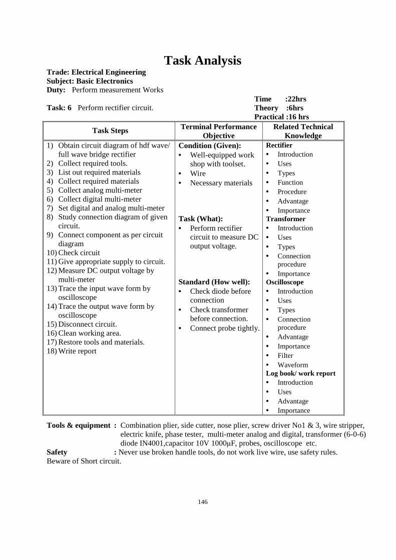
146
Task Analysis Trade: Electrical Engineering Subject: Basic Electronics Duty: Perform measurement Works Task: 6 Perform rectifier circuit.
Time :22hrs Theory :6hrs Practical :16 hrs
Task Steps Terminal Performance Objective
Related Technical Knowledge
1) Obtain circuit diagram of hdf wave/ full wave bridge rectifier
2) Collect required tools. 3) List out required materials 4) Collect required materials 5) Collect analog multi-meter 6) Collect digital multi-meter 7) Set digital and analog multi-meter 8) Study connection diagram of given
circuit. 9) Connect component as per circuit
diagram 10) Check circuit 11) Give appropriate supply to circuit. 12) Measure DC output voltage by
multi-meter 13) Trace the input wave form by
oscilloscope 14) Trace the output wave form by
oscilloscope 15) Disconnect circuit. 16) Clean working area. 17) Restore tools and materials. 18) Write report
Condition (Given): • Well-equipped work
shop with toolset. • Wire • Necessary materials Task (What): • Perform rectifier
circuit to measure DC output voltage.
Standard (How well): • Check diode before
connection • Check transformer
before connection. • Connect probe tightly.
Rectifier • Introduction • Uses • Types • Function • Procedure • Advantage • Importance Transformer • Introduction • Uses • Types • Connection
procedure • Importance Oscilloscope • Introduction • Uses • Types • Connection
procedure • Advantage • Importance • Filter • Waveform Log book/ work report • Introduction • Uses • Advantage • Importance
Tools & equipment : Combination plier, side cutter, nose plier, screw driver No1 & 3, wire stripper, electric knife, phase tester, multi-meter analog and digital, transformer (6-0-6) diode IN4001,capacitor 10V 1000µF, probes, oscilloscope etc.
Safety : Never use broken handle tools, do not work live wire, use safety rules. Beware of Short circuit.
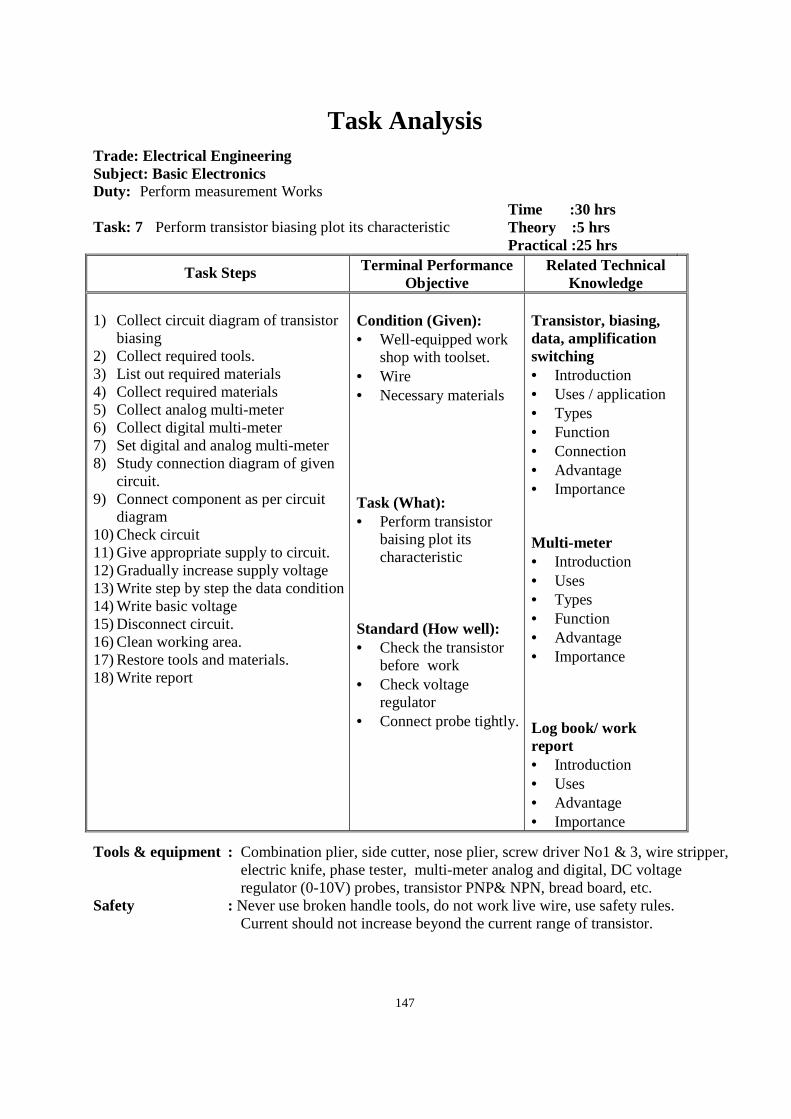
147
Task Analysis
Trade: Electrical Engineering Subject: Basic Electronics Duty: Perform measurement Works Task: 7 Perform transistor biasing plot its characteristic
Time :30 hrs Theory :5 hrs Practical :25 hrs
Task Steps Terminal Performance Objective
Related Technical Knowledge
1) Collect circuit diagram of transistor
biasing 2) Collect required tools. 3) List out required materials 4) Collect required materials 5) Collect analog multi-meter 6) Collect digital multi-meter 7) Set digital and analog multi-meter 8) Study connection diagram of given
circuit. 9) Connect component as per circuit
diagram 10) Check circuit 11) Give appropriate supply to circuit. 12) Gradually increase supply voltage 13) Write step by step the data condition 14) Write basic voltage 15) Disconnect circuit. 16) Clean working area. 17) Restore tools and materials. 18) Write report
Condition (Given): • Well-equipped work
shop with toolset. • Wire • Necessary materials Task (What): • Perform transistor
baising plot its characteristic
Standard (How well): • Check the transistor
before work • Check voltage
regulator • Connect probe tightly.
Transistor, biasing, data, amplification switching • Introduction • Uses / application • Types • Function • Connection • Advantage • Importance Multi-meter • Introduction • Uses • Types • Function • Advantage • Importance Log book/ work report • Introduction • Uses • Advantage • Importance
Tools & equipment : Combination plier, side cutter, nose plier, screw driver No1 & 3, wire stripper, electric knife, phase tester, multi-meter analog and digital, DC voltage regulator (0-10V) probes, transistor PNP& NPN, bread board, etc.
Safety : Never use broken handle tools, do not work live wire, use safety rules. Current should not increase beyond the current range of transistor.
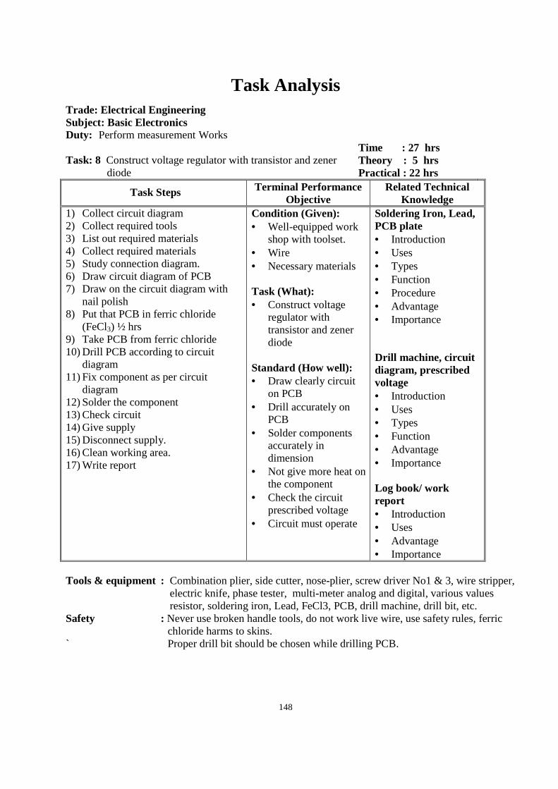
148
Task Analysis
Trade: Electrical Engineering Subject: Basic Electronics Duty: Perform measurement Works Task: 8 Construct voltage regulator with transistor and zener
diode
Time : 27 hrs Theory : 5 hrs Practical : 22 hrs
Task Steps Terminal Performance Objective
Related Technical Knowledge
1) Collect circuit diagram 2) Collect required tools 3) List out required materials 4) Collect required materials 5) Study connection diagram. 6) Draw circuit diagram of PCB 7) Draw on the circuit diagram with
nail polish 8) Put that PCB in ferric chloride
(FeCl3) ½ hrs 9) Take PCB from ferric chloride 10) Drill PCB according to circuit
diagram 11) Fix component as per circuit
diagram 12) Solder the component 13) Check circuit 14) Give supply 15) Disconnect supply. 16) Clean working area. 17) Write report
Condition (Given): • Well-equipped work
shop with toolset. • Wire • Necessary materials Task (What): • Construct voltage
regulator with transistor and zener diode
Standard (How well): • Draw clearly circuit
on PCB • Drill accurately on
PCB • Solder components
accurately in dimension
• Not give more heat on the component
• Check the circuit prescribed voltage
• Circuit must operate
Soldering Iron, Lead, PCB plate • Introduction • Uses • Types • Function • Procedure • Advantage • Importance Drill machine, circuit diagram, prescribed voltage • Introduction • Uses • Types • Function • Advantage • Importance Log book/ work report • Introduction • Uses • Advantage • Importance
Tools & equipment : Combination plier, side cutter, nose-plier, screw driver No1 & 3, wire stripper, electric knife, phase tester, multi-meter analog and digital, various values resistor, soldering iron, Lead, FeCl3, PCB, drill machine, drill bit, etc.
Safety : Never use broken handle tools, do not work live wire, use safety rules, ferric chloride harms to skins.
` Proper drill bit should be chosen while drilling PCB.
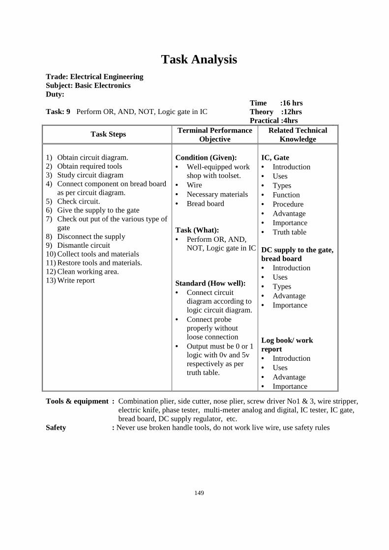
149
Task Analysis
Trade: Electrical Engineering Subject: Basic Electronics Duty: Task: 9 Perform OR, AND, NOT, Logic gate in IC
Time :16 hrs Theory :12hrs Practical :4hrs
Task Steps Terminal Performance Objective
Related Technical Knowledge
1) Obtain circuit diagram. 2) Obtain required tools 3) Study circuit diagram 4) Connect component on bread board
as per circuit diagram. 5) Check circuit. 6) Give the supply to the gate 7) Check out put of the various type of
gate 8) Disconnect the supply 9) Dismantle circuit 10) Collect tools and materials 11) Restore tools and materials. 12) Clean working area. 13) Write report
Condition (Given): • Well-equipped work
shop with toolset. • Wire • Necessary materials • Bread board Task (What): • Perform OR, AND,
NOT, Logic gate in IC Standard (How well): • Connect circuit
diagram according to logic circuit diagram.
• Connect probe properly without loose connection
• Output must be 0 or 1 logic with 0v and 5v respectively as per truth table.
IC, Gate • Introduction • Uses • Types • Function • Procedure • Advantage • Importance • Truth table DC supply to the gate, bread board • Introduction • Uses • Types • Advantage • Importance Log book/ work report • Introduction • Uses • Advantage • Importance
Tools & equipment : Combination plier, side cutter, nose plier, screw driver No1 & 3, wire stripper, electric knife, phase tester, multi-meter analog and digital, IC tester, IC gate, bread board, DC supply regulator, etc.
Safety : Never use broken handle tools, do not work live wire, use safety rules
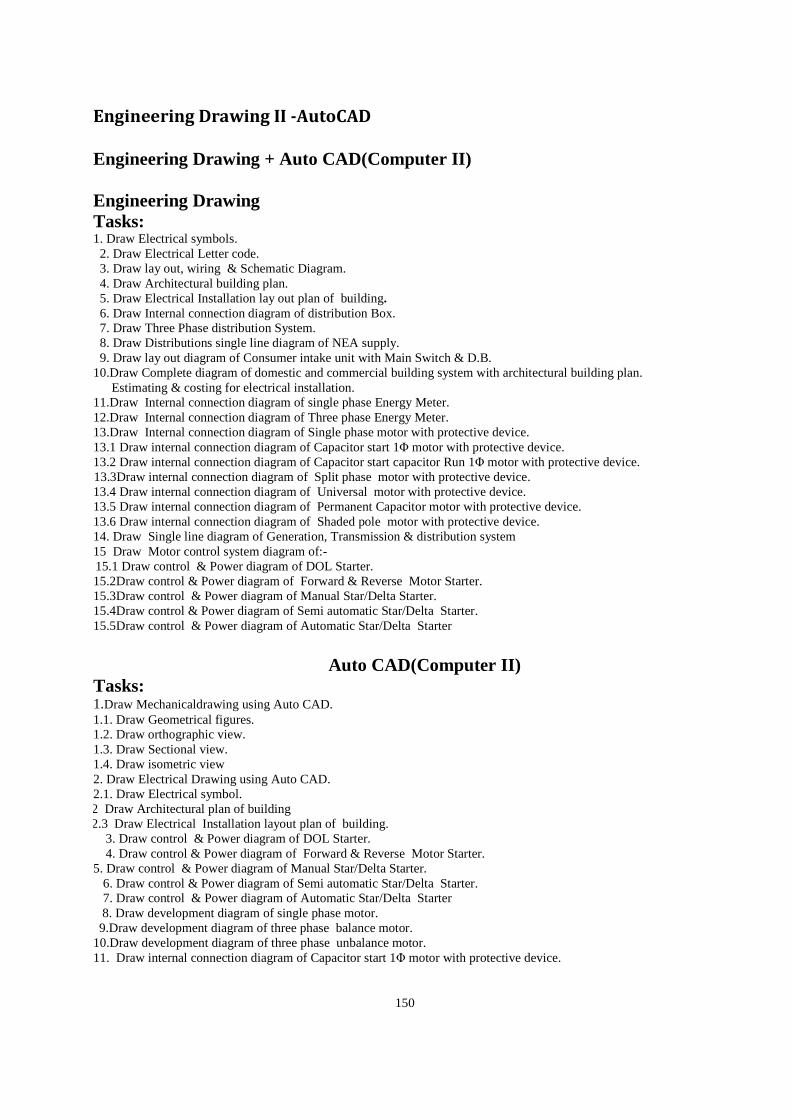
150
Engineering Drawing II -AutoCAD
Engineering Drawing + Auto CAD(Computer II) Engineering Drawing Tasks: 1. Draw Electrical symbols. 2. Draw Electrical Letter code. 3. Draw lay out, wiring & Schematic Diagram. 4. Draw Architectural building plan. 5. Draw Electrical Installation lay out plan of building. 6. Draw Internal connection diagram of distribution Box. 7. Draw Three Phase distribution System. 8. Draw Distributions single line diagram of NEA supply. 9. Draw lay out diagram of Consumer intake unit with Main Switch & D.B. 10.Draw Complete diagram of domestic and commercial building system with architectural building plan.
Estimating & costing for electrical installation. 11.Draw Internal connection diagram of single phase Energy Meter. 12.Draw Internal connection diagram of Three phase Energy Meter. 13.Draw Internal connection diagram of Single phase motor with protective device. 13.1 Draw internal connection diagram of Capacitor start 1Φ motor with protective device. 13.2 Draw internal connection diagram of Capacitor start capacitor Run 1Φ motor with protective device.
13.3Draw internal connection diagram of Split phase motor with protective device. 13.4 Draw internal connection diagram of Universal motor with protective device. 13.5 Draw internal connection diagram of Permanent Capacitor motor with protective device. 13.6 Draw internal connection diagram of Shaded pole motor with protective device. 14. Draw Single line diagram of Generation, Transmission & distribution system 15 Draw Motor control system diagram of:- 15.1 Draw control & Power diagram of DOL Starter. 15.2Draw control & Power diagram of Forward & Reverse Motor Starter. 15.3Draw control & Power diagram of Manual Star/Delta Starter. 15.4Draw control & Power diagram of Semi automatic Star/Delta Starter. 15.5Draw control & Power diagram of Automatic Star/Delta Starter
Auto CAD(Computer II)
Tasks: 1.Draw Mechanicaldrawing using Auto CAD. 1.1. Draw Geometrical figures. 1.2. Draw orthographic view. 1.3. Draw Sectional view. 1.4. Draw isometric view 2. Draw Electrical Drawing using Auto CAD. 2.1. Draw Electrical symbol.
2.2 Draw Architectural plan of building 2.2.3 Draw Electrical Installation layout plan of building.
3. Draw control & Power diagram of DOL Starter. 4. Draw control & Power diagram of Forward & Reverse Motor Starter.
5. Draw control & Power diagram of Manual Star/Delta Starter. 6. Draw control & Power diagram of Semi automatic Star/Delta Starter. 7. Draw control & Power diagram of Automatic Star/Delta Starter
8. Draw development diagram of single phase motor. 9.Draw development diagram of three phase balance motor.
10.Draw development diagram of three phase unbalance motor. 11. Draw internal connection diagram of Capacitor start 1Φ motor with protective device.

151
12. Draw internal connection diagram of Capacitor start capacitor Run 1Φ motor with protective device. 13. Draw internal connection diagram of Split phase motor with protective device. 14. Draw internal connection diagram of Universal motor with protective device. 15. Draw internal connection diagram of Permanent Capacitor motor with protective device. 16. Draw internal connection diagram of Shaded pole motor with protective device. 17. Draw lay out diagram of single phase service drops 18. Draw lay out diagram of three phase service drops
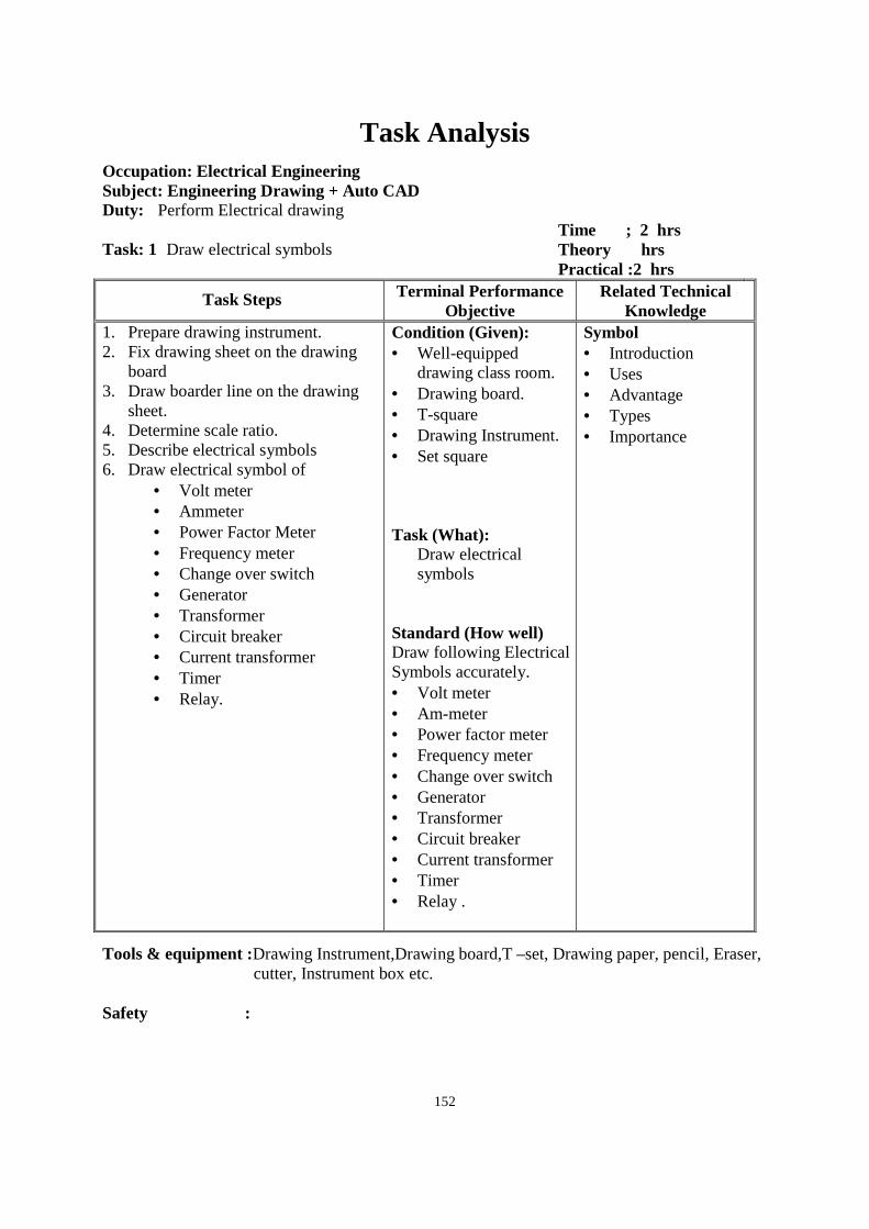
152
Task Analysis
Occupation: Electrical Engineering Subject: Engineering Drawing + Auto CAD Duty: Perform Electrical drawing Task: 1 Draw electrical symbols
Time ; 2 hrs Theory hrs Practical :2 hrs
Task Steps Terminal Performance Objective
Related Technical Knowledge
1. Prepare drawing instrument. 2. Fix drawing sheet on the drawing
board 3. Draw boarder line on the drawing
sheet. 4. Determine scale ratio. 5. Describe electrical symbols 6. Draw electrical symbol of
• Volt meter • Ammeter • Power Factor Meter • Frequency meter • Change over switch • Generator • Transformer • Circuit breaker • Current transformer • Timer • Relay.
Condition (Given): • Well-equipped
drawing class room. • Drawing board. • T-square • Drawing Instrument. • Set square Task (What):
Draw electrical symbols
Standard (How well) Draw following Electrical Symbols accurately. • Volt meter • Am-meter • Power factor meter • Frequency meter • Change over switch • Generator • Transformer • Circuit breaker • Current transformer • Timer • Relay .
Symbol • Introduction • Uses • Advantage • Types • Importance
Tools & equipment :Drawing Instrument,Drawing board,T –set, Drawing paper, pencil, Eraser, cutter, Instrument box etc.
Safety :
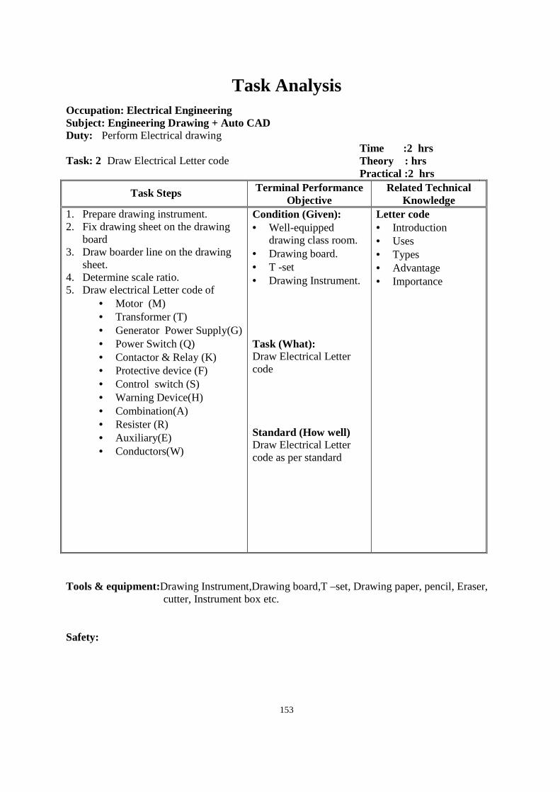
153
Task Analysis
Occupation: Electrical Engineering Subject: Engineering Drawing + Auto CAD Duty: Perform Electrical drawing Task: 2 Draw Electrical Letter code
Time :2 hrs Theory : hrs Practical :2 hrs
Task Steps Terminal Performance Objective
Related Technical Knowledge
1. Prepare drawing instrument. 2. Fix drawing sheet on the drawing
board 3. Draw boarder line on the drawing
sheet. 4. Determine scale ratio. 5. Draw electrical Letter code of
• Motor (M) • Transformer (T) • Generator Power Supply(G) • Power Switch (Q) • Contactor & Relay (K) • Protective device (F) • Control switch (S) • Warning Device(H) • Combination(A) • Resister (R) • Auxiliary(E) • Conductors(W)
Condition (Given): • Well-equipped
drawing class room. • Drawing board. • T -set • Drawing Instrument. Task (What): Draw Electrical Letter code Standard (How well) Draw Electrical Letter code as per standard
Letter code • Introduction • Uses • Types • Advantage • Importance
Tools & equipment:Drawing Instrument,Drawing board,T –set, Drawing paper, pencil, Eraser,
cutter, Instrument box etc. Safety:
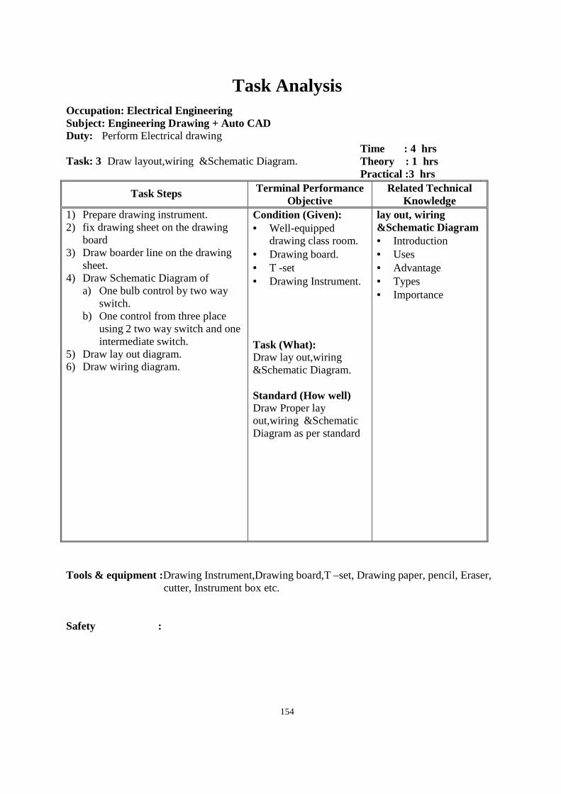
154
Task Analysis
Occupation: Electrical Engineering Subject: Engineering Drawing + Auto CAD Duty: Perform Electrical drawing Task: 3 Draw layout,wiring &Schematic Diagram.
Time : 4 hrs Theory : 1 hrs Practical :3 hrs
Task Steps Terminal Performance Objective
Related Technical Knowledge
1) Prepare drawing instrument. 2) fix drawing sheet on the drawing
board 3) Draw boarder line on the drawing
sheet. 4) Draw Schematic Diagram of
a) One bulb control by two way switch.
b) One control from three place using 2 two way switch and one intermediate switch.
5) Draw lay out diagram. 6) Draw wiring diagram.
Condition (Given): • Well-equipped
drawing class room. • Drawing board. • T -set • Drawing Instrument. Task (What): Draw lay out,wiring &Schematic Diagram. Standard (How well) Draw Proper lay out,wiring &Schematic Diagram as per standard
lay out, wiring &Schematic Diagram • Introduction • Uses • Advantage • Types • Importance
Tools & equipment :Drawing Instrument,Drawing board,T –set, Drawing paper, pencil, Eraser,
cutter, Instrument box etc. Safety :
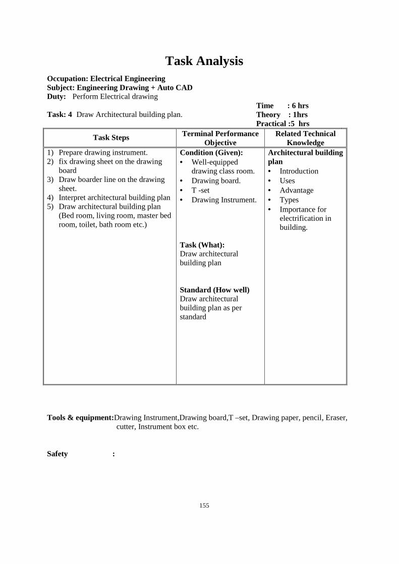
155
Task Analysis
Occupation: Electrical Engineering Subject: Engineering Drawing + Auto CAD Duty: Perform Electrical drawing Task: 4 Draw Architectural building plan.
Time : 6 hrs Theory : 1hrs Practical :5 hrs
Task Steps Terminal Performance Objective
Related Technical Knowledge
1) Prepare drawing instrument. 2) fix drawing sheet on the drawing
board 3) Draw boarder line on the drawing
sheet. 4) Interpret architectural building plan 5) Draw architectural building plan
(Bed room, living room, master bed room, toilet, bath room etc.)
Condition (Given): • Well-equipped
drawing class room. • Drawing board. • T -set • Drawing Instrument. Task (What): Draw architectural building plan Standard (How well) Draw architectural building plan as per standard
Architectural building plan • Introduction • Uses • Advantage • Types • Importance for
electrification in building.
Tools & equipment:Drawing Instrument,Drawing board,T –set, Drawing paper, pencil, Eraser,
cutter, Instrument box etc. Safety :
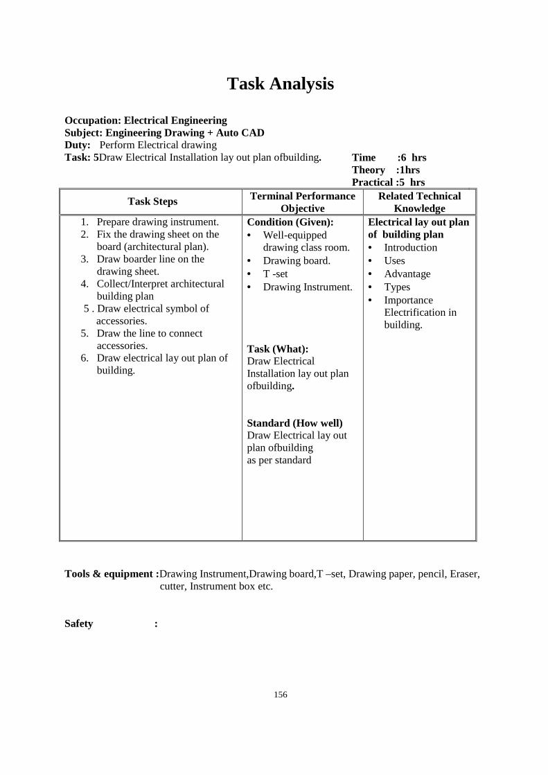
156
Task Analysis
Occupation: Electrical Engineering Subject: Engineering Drawing + Auto CAD Duty: Perform Electrical drawing Task: 5Draw Electrical Installation lay out plan ofbuilding.
Time :6 hrs Theory :1hrs Practical :5 hrs
Task Steps Terminal Performance Objective
Related Technical Knowledge
1. Prepare drawing instrument. 2. Fix the drawing sheet on the
board (architectural plan). 3. Draw boarder line on the
drawing sheet. 4. Collect/Interpret architectural
building plan 5 . Draw electrical symbol of
accessories. 5. Draw the line to connect
accessories. 6. Draw electrical lay out plan of
building.
Condition (Given): • Well-equipped
drawing class room. • Drawing board. • T -set • Drawing Instrument. Task (What): Draw Electrical Installation lay out plan ofbuilding. Standard (How well) Draw Electrical lay out plan ofbuilding as per standard
Electrical lay out plan of building plan • Introduction • Uses • Advantage • Types • Importance
Electrification in building.
Tools & equipment :Drawing Instrument,Drawing board,T –set, Drawing paper, pencil, Eraser,
cutter, Instrument box etc. Safety :
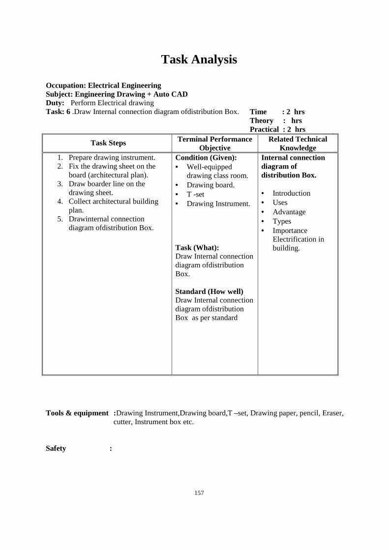
157
Task Analysis
Occupation: Electrical Engineering Subject: Engineering Drawing + Auto CAD Duty: Perform Electrical drawing Task: 6 .Draw Internal connection diagram ofdistribution Box.
Time : 2 hrs Theory : hrs Practical : 2 hrs
Task Steps Terminal Performance Objective
Related Technical Knowledge
1. Prepare drawing instrument. 2. Fix the drawing sheet on the
board (architectural plan). 3. Draw boarder line on the
drawing sheet. 4. Collect architectural building
plan. 5. Drawinternal connection
diagram ofdistribution Box.
Condition (Given): • Well-equipped
drawing class room. • Drawing board. • T -set • Drawing Instrument. Task (What): Draw Internal connection diagram ofdistribution Box. Standard (How well) Draw Internal connection diagram ofdistribution Box as per standard
Internal connection diagram of distribution Box. • Introduction • Uses • Advantage • Types • Importance
Electrification in building.
Tools & equipment :Drawing Instrument,Drawing board,T –set, Drawing paper, pencil, Eraser, cutter, Instrument box etc.
Safety :
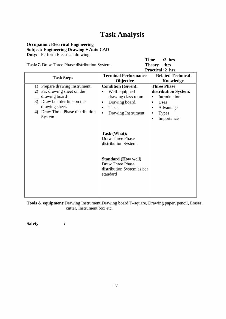
158
Task Analysis
Occupation: Electrical Engineering Subject: Engineering Drawing + Auto CAD Duty: Perform Electrical drawing Task:7. Draw Three Phase distribution System.
Time :2 hrs Theory :hrs Practical :2 hrs
Task Steps Terminal Performance Objective
Related Technical Knowledge
1) Prepare drawing instrument. 2) Fix drawing sheet on the
drawing board 3) Draw boarder line on the
drawing sheet. 4) Draw Three Phase distribution
System.
Condition (Given): • Well-equipped
drawing class room. • Drawing board. • T -set • Drawing Instrument. Task (What): Draw Three Phase distribution System. Standard (How well) Draw Three Phase distribution System as per standard
Three Phase distribution System. • Introduction • Uses • Advantage • Types • Importance
Tools & equipment:Drawing Instrument,Drawing board,T–square, Drawing paper, pencil, Eraser, cutter, Instrument box etc.
Safety :
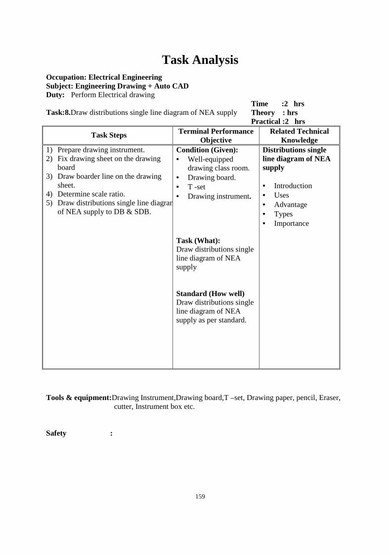
159
Task Analysis
Occupation: Electrical Engineering Subject: Engineering Drawing + Auto CAD Duty: Perform Electrical drawing Task:8.Draw distributions single line diagram of NEA supply
Time :2 hrs Theory : hrs Practical :2 hrs
Task Steps Terminal Performance Objective
Related Technical Knowledge
1) Prepare drawing instrument. 2) Fix drawing sheet on the drawing
board 3) Draw boarder line on the drawing
sheet. 4) Determine scale ratio. 5) Draw distributions single line diagram
of NEA supply to DB & SDB.
Condition (Given): • Well-equipped
drawing class room. • Drawing board. • T -set • Drawing instrument. Task (What): Draw distributions single line diagram of NEA supply Standard (How well) Draw distributions single line diagram of NEA supply as per standard.
Distributions single line diagram of NEA supply • Introduction • Uses • Advantage • Types • Importance
Tools & equipment:Drawing Instrument,Drawing board,T –set, Drawing paper, pencil, Eraser, cutter, Instrument box etc.
Safety :
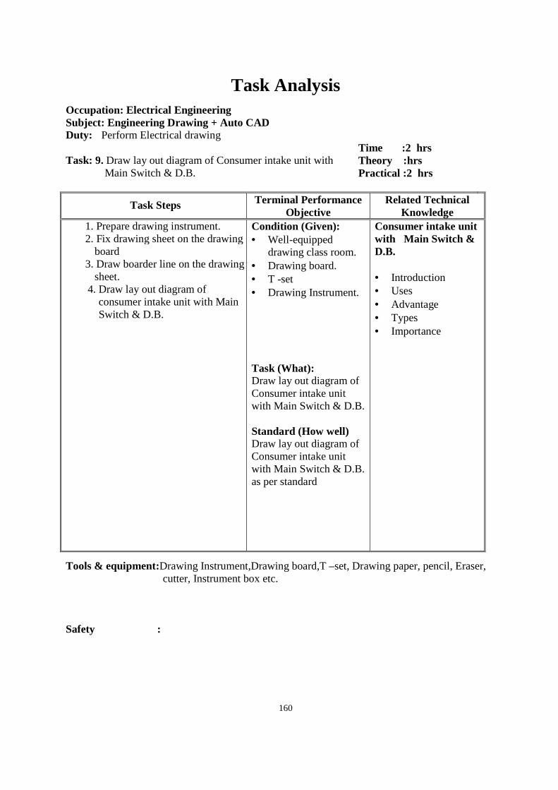
160
Task Analysis
Occupation: Electrical Engineering Subject: Engineering Drawing + Auto CAD Duty: Perform Electrical drawing Task: 9. Draw lay out diagram of Consumer intake unit with
Main Switch & D.B.
Time :2 hrs Theory :hrs Practical :2 hrs
Task Steps Terminal Performance Objective
Related Technical Knowledge
1. Prepare drawing instrument. 2. Fix drawing sheet on the drawing
board 3. Draw boarder line on the drawing
sheet. 4. Draw lay out diagram of
consumer intake unit with Main Switch & D.B.
Condition (Given): • Well-equipped
drawing class room. • Drawing board. • T -set • Drawing Instrument. Task (What): Draw lay out diagram of Consumer intake unit with Main Switch & D.B. Standard (How well) Draw lay out diagram of Consumer intake unit with Main Switch & D.B. as per standard
Consumer intake unit with Main Switch & D.B. • Introduction • Uses • Advantage • Types • Importance
Tools & equipment:Drawing Instrument,Drawing board,T –set, Drawing paper, pencil, Eraser, cutter, Instrument box etc.
Safety :
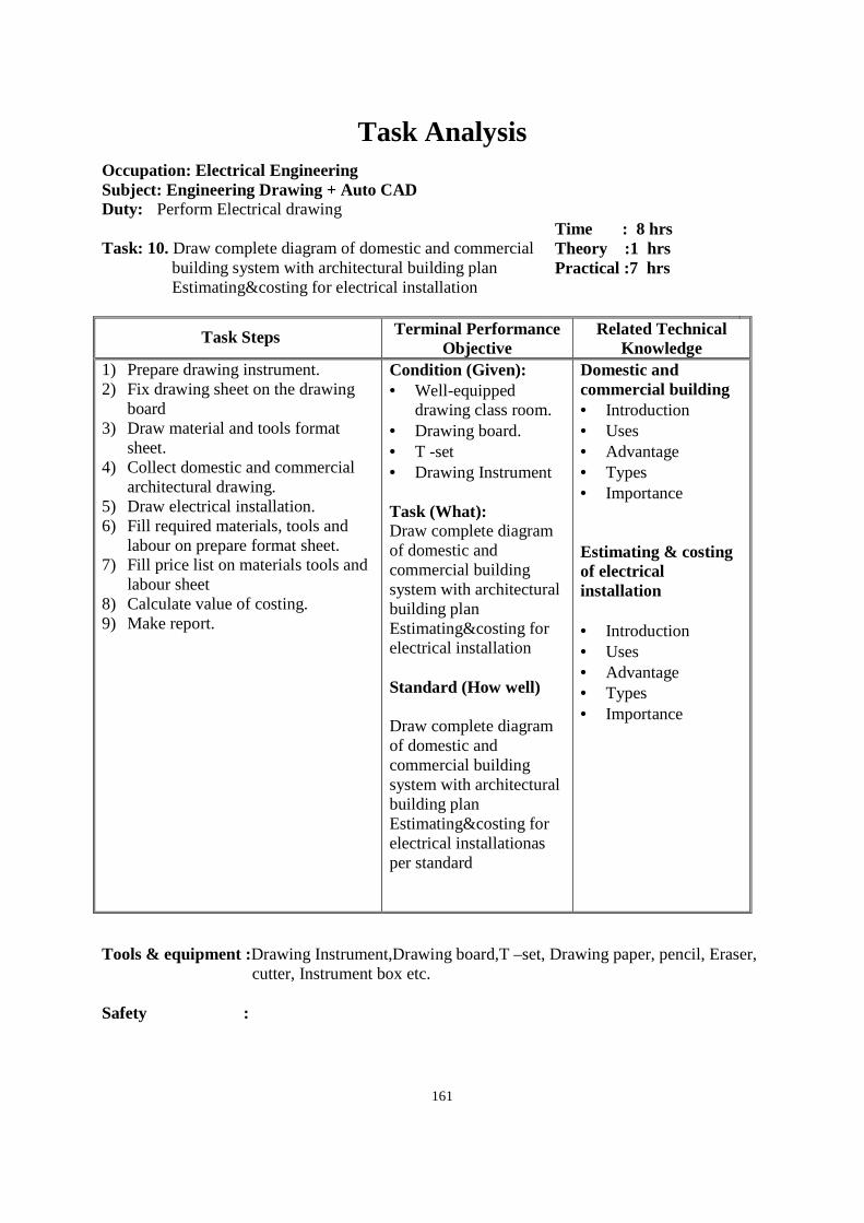
161
Task Analysis
Occupation: Electrical Engineering Subject: Engineering Drawing + Auto CAD Duty: Perform Electrical drawing Task: 10. Draw complete diagram of domestic and commercial
building system with architectural building plan Estimating&costing for electrical installation
Time : 8 hrs Theory :1 hrs Practical :7 hrs
Task Steps Terminal Performance Objective
Related Technical Knowledge
1) Prepare drawing instrument. 2) Fix drawing sheet on the drawing
board 3) Draw material and tools format
sheet. 4) Collect domestic and commercial
architectural drawing. 5) Draw electrical installation. 6) Fill required materials, tools and
labour on prepare format sheet. 7) Fill price list on materials tools and
labour sheet 8) Calculate value of costing. 9) Make report.
Condition (Given): • Well-equipped
drawing class room. • Drawing board. • T -set • Drawing Instrument Task (What): Draw complete diagram of domestic and commercial building system with architectural building plan Estimating&costing for electrical installation Standard (How well) Draw complete diagram of domestic and commercial building system with architectural building plan Estimating&costing for electrical installationas per standard
Domestic and commercial building • Introduction • Uses • Advantage • Types • Importance Estimating & costing of electrical installation • Introduction • Uses • Advantage • Types • Importance
Tools & equipment :Drawing Instrument,Drawing board,T –set, Drawing paper, pencil, Eraser,
cutter, Instrument box etc. Safety :
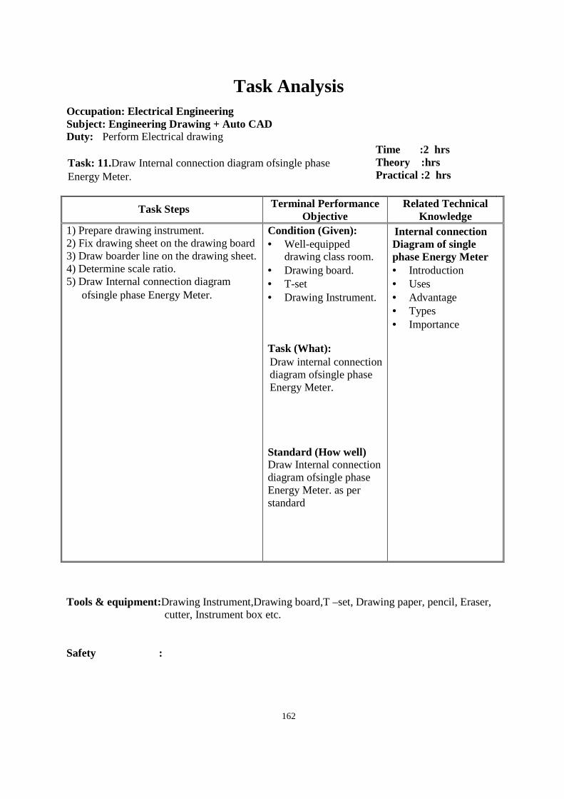
162
Task Analysis
Occupation: Electrical Engineering Subject: Engineering Drawing + Auto CAD Duty: Perform Electrical drawing Task: 11.Draw Internal connection diagram ofsingle phase Energy Meter.
Time :2 hrs Theory :hrs Practical :2 hrs
Task Steps Terminal Performance Objective
Related Technical Knowledge
1) Prepare drawing instrument. 2) Fix drawing sheet on the drawing board 3) Draw boarder line on the drawing sheet. 4) Determine scale ratio. 5) Draw Internal connection diagram
ofsingle phase Energy Meter.
Condition (Given): • Well-equipped
drawing class room. • Drawing board. • T-set • Drawing Instrument. Task (What): Draw internal connection diagram ofsingle phase Energy Meter.
Standard (How well) Draw Internal connection diagram ofsingle phase Energy Meter. as per standard
Internal connection Diagram of single phase Energy Meter • Introduction • Uses • Advantage • Types • Importance
Tools & equipment:Drawing Instrument,Drawing board,T –set, Drawing paper, pencil, Eraser,
cutter, Instrument box etc. Safety :
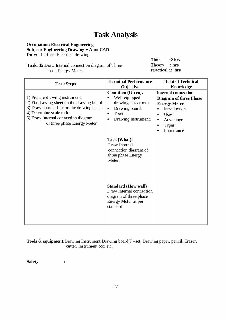
163
Task Analysis
Occupation: Electrical Engineering Subject: Engineering Drawing + Auto CAD Duty: Perform Electrical drawing Task: 12.Draw Internal connection diagram of Three
Phase Energy Meter.
Time :2 hrs Theory : hrs Practical :2 hrs
Task Steps Terminal Performance Objective
Related Technical Knowledge
1) Prepare drawing instrument. 2) Fix drawing sheet on the drawing board 3) Draw boarder line on the drawing sheet. 4) Determine scale ratio. 5) Draw Internal connection diagram
of three phase Energy Meter.
Condition (Given): • Well-equipped
drawing class room. • Drawing board. • T-set • Drawing Instrument. Task (What): Draw Internal connection diagram of three phase Energy Meter.
Standard (How well) Draw Internal connection diagram of three phase Energy Meter as per standard
Internal connection Diagram of three Phase Energy Meter • Introduction • Uses • Advantage • Types • Importance
Tools & equipment:Drawing Instrument,Drawing board,T –set, Drawing paper, pencil, Eraser,
cutter, Instrument box etc. Safety :

164
Task Analysis
Occupation: Electrical Engineering Subject: Engineering Drawing + Auto CAD Duty: Perform Electrical drawing Task: 13.1Draw internal connection diagram of Capacitor start
motor with protective device.
Time :2 hrs Theory :hrs Practical :2 hrs
Task Steps Terminal Performance Objective
Related Technical Knowledge
1) Prepare drawing instrument. 2) Fix drawing sheet on the drawing
board 3) Draw boarder line on the drawing
sheet. 4) Determine scale ratio. 5) Draw internal connection diagram of
Capacitor start 1Φ motor with protective device.
Condition (Given): • Well-equipped
drawing class room. • Drawing board. • T -set • Drawing Instrument Task (What): Draw internal connection diagram of Capacitor start 1Φ motor with protective device. Standard (How well) Draw internal connection diagram of Capacitor start 1Φ motor with protective device as per standard
Internal connection diagram of Capacitor start 1Φ motor withprotective device. • Introduction • Uses • Advantage • Types • Importance
Tools & equipment:Drawing Instrument,Drawing board,T –set, Drawing paper, pencil, Eraser, cutter, Instrument box etc.
Safety :
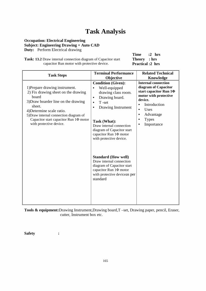
165
Task Analysis
Occupation: Electrical Engineering Subject: Engineering Drawing + Auto CAD Duty: Perform Electrical drawing Task: 13.2 Draw internal connection diagram of Capacitor start
capacitor Run motor with protective device.
Time :2 hrs Theory : hrs Practical :2 hrs
Task Steps Terminal Performance Objective
Related Technical Knowledge
1)Prepare drawing instrument. 2) Fix drawing sheet on the drawing
board 3)Draw boarder line on the drawing
sheet. 4)Determine scale ratio. 5)Draw internal connection diagram of
Capacitor start capacitor Run 1Φ motor with protective device.
Condition (Given): • Well-equipped
drawing class room. • Drawing board. • T -set • Drawing Instrument Task (What): Draw internal connection diagram of Capacitor start capacitor Run 1Φ motor with protective device. Standard (How well) Draw internal connection diagram of Capacitor start capacitor Run 1Φ motor with protective deviceas per standard
Internal connection diagram of Capacitor start capacitor Run 1Φ motor with protective device. • Introduction • Uses • Advantage • Types • Importance
Tools & equipment:Drawing Instrument,Drawing board,T –set, Drawing paper, pencil, Eraser, cutter, Instrument box etc.
Safety :
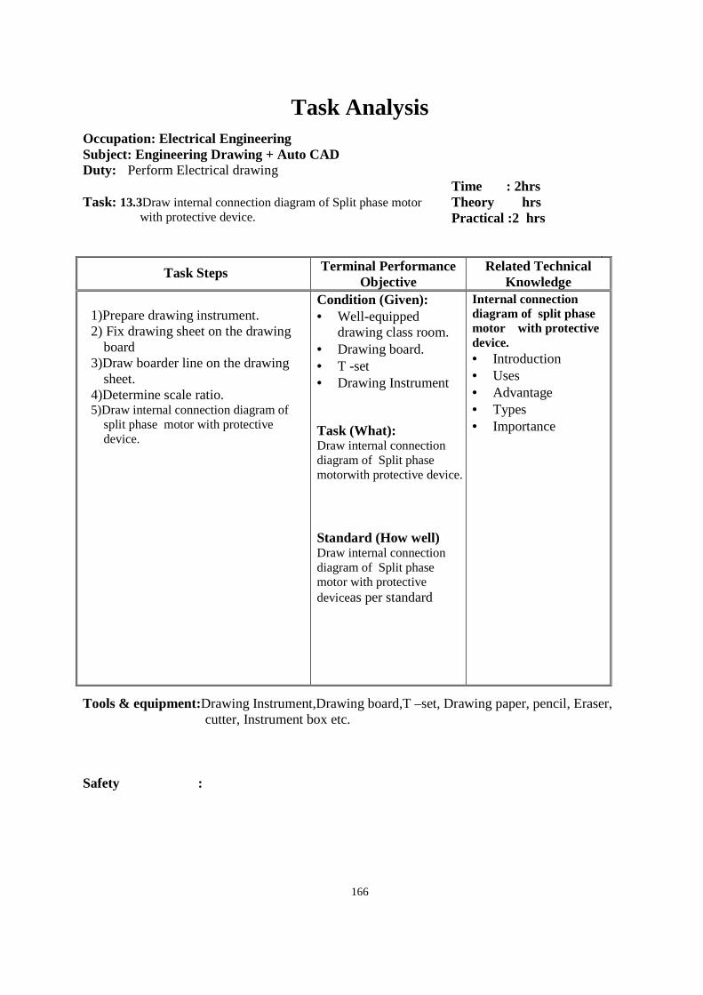
166
Task Analysis
Occupation: Electrical Engineering Subject: Engineering Drawing + Auto CAD Duty: Perform Electrical drawing Task: 13.3Draw internal connection diagram of Split phase motor
with protective device.
Time : 2hrs Theory hrs Practical :2 hrs
Task Steps Terminal Performance Objective
Related Technical Knowledge
1)Prepare drawing instrument. 2) Fix drawing sheet on the drawing
board 3)Draw boarder line on the drawing
sheet. 4)Determine scale ratio. 5)Draw internal connection diagram of
split phase motor with protective device.
Condition (Given): • Well-equipped
drawing class room. • Drawing board. • T -set • Drawing Instrument Task (What): Draw internal connection diagram of Split phase motorwith protective device. Standard (How well) Draw internal connection diagram of Split phase motor with protective deviceas per standard
Internal connection diagram of split phase motor with protective device. • Introduction • Uses • Advantage • Types • Importance
Tools & equipment:Drawing Instrument,Drawing board,T –set, Drawing paper, pencil, Eraser, cutter, Instrument box etc.
Safety :
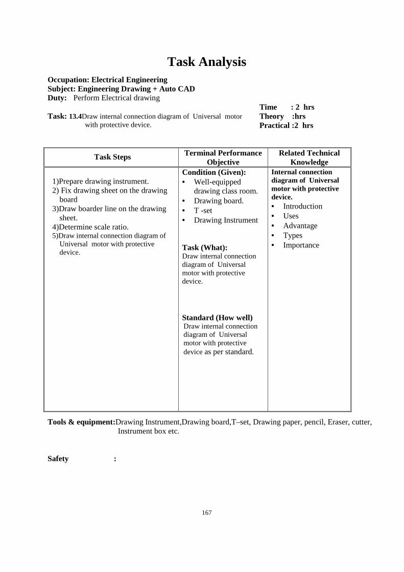
167
Task Analysis
Occupation: Electrical Engineering Subject: Engineering Drawing + Auto CAD Duty: Perform Electrical drawing Task: 13.4Draw internal connection diagram of Universal motor
with protective device.
Time : 2 hrs Theory :hrs Practical :2 hrs
Task Steps Terminal Performance Objective
Related Technical Knowledge
1)Prepare drawing instrument. 2) Fix drawing sheet on the drawing
board 3)Draw boarder line on the drawing
sheet. 4)Determine scale ratio. 5)Draw internal connection diagram of
Universal motor with protective device.
Condition (Given): • Well-equipped
drawing class room. • Drawing board. • T -set • Drawing Instrument Task (What): Draw internal connection diagram of Universal motor with protective device. Standard (How well) Draw internal connection diagram of Universal motor with protective device as per standard.
Internal connection diagram of Universal motor with protective device. • Introduction • Uses • Advantage • Types • Importance
Tools & equipment:Drawing Instrument,Drawing board,T–set, Drawing paper, pencil, Eraser, cutter, Instrument box etc.
Safety :
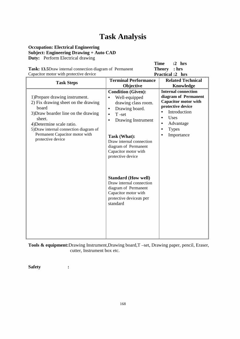
168
Task Analysis
Occupation: Electrical Engineering Subject: Engineering Drawing + Auto CAD Duty: Perform Electrical drawing Task: 13.5Draw internal connection diagram of Permanent Capacitor motor with protective device
Time :2 hrs Theory : hrs Practical :2 hrs
Task Steps Terminal Performance Objective
Related Technical Knowledge
1)Prepare drawing instrument. 2) Fix drawing sheet on the drawing
board 3)Draw boarder line on the drawing
sheet. 4)Determine scale ratio. 5)Draw internal connection diagram of
Permanent Capacitor motor with protective device
Condition (Given): • Well-equipped
drawing class room. • Drawing board. • T -set • Drawing Instrument Task (What): Draw internal connection diagram of Permanent Capacitor motor with protective device Standard (How well) Draw internal connection diagram of Permanent Capacitor motor with protective deviceas per standard
Internal connection diagram of Permanent Capacitor motor with protective device • Introduction • Uses • Advantage • Types • Importance
Tools & equipment:Drawing Instrument,Drawing board,T –set, Drawing paper, pencil, Eraser, cutter, Instrument box etc.
Safety :
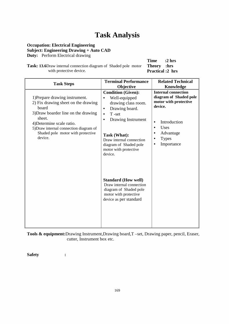
169
Task Analysis
Occupation: Electrical Engineering Subject: Engineering Drawing + Auto CAD Duty: Perform Electrical drawing Task: 13.6Draw internal connection diagram of Shaded pole motor
with protective device.
Time :2 hrs Theory :hrs Practical :2 hrs
Task Steps Terminal Performance Objective
Related Technical Knowledge
1)Prepare drawing instrument. 2) Fix drawing sheet on the drawing
board 3)Draw boarder line on the drawing
sheet. 4)Determine scale ratio. 5)Draw internal connection diagram of
Shaded pole motor with protective device.
Condition (Given): • Well-equipped
drawing class room. • Drawing board. • T -set • Drawing Instrument Task (What): Draw internal connection diagram of Shaded pole motor with protective device. Standard (How well) Draw internal connection diagram of Shaded pole motor with protective device as per standard
Internal connection diagram of Shaded pole motor with protective device. • Introduction • Uses • Advantage • Types • Importance
Tools & equipment:Drawing Instrument,Drawing board,T –set, Drawing paper, pencil, Eraser, cutter, Instrument box etc.
Safety :
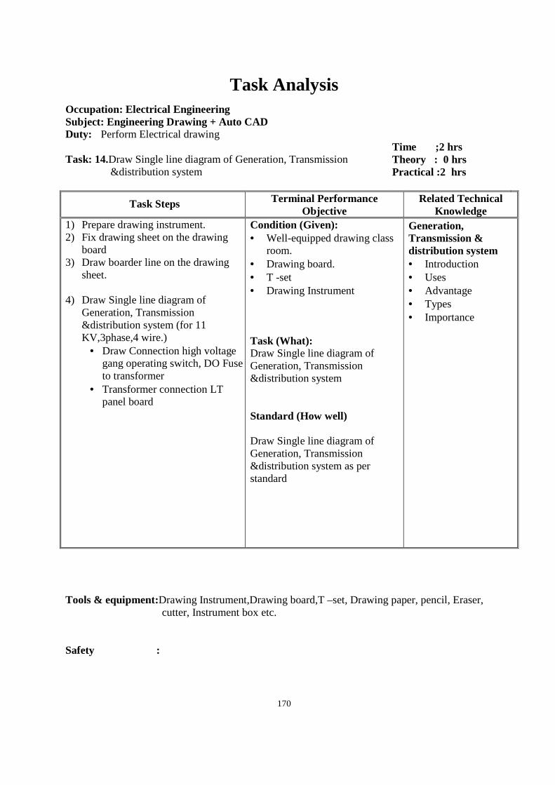
170
Task Analysis
Occupation: Electrical Engineering Subject: Engineering Drawing + Auto CAD Duty: Perform Electrical drawing Task: 14.Draw Single line diagram of Generation, Transmission
&distribution system
Time ;2 hrs Theory : 0 hrs Practical :2 hrs
Task Steps Terminal Performance Objective
Related Technical Knowledge
1) Prepare drawing instrument. 2) Fix drawing sheet on the drawing
board 3) Draw boarder line on the drawing
sheet. 4) Draw Single line diagram of
Generation, Transmission &distribution system (for 11 KV,3phase,4 wire.)
• Draw Connection high voltage gang operating switch, DO Fuse to transformer
• Transformer connection LT panel board
Condition (Given): • Well-equipped drawing class
room. • Drawing board. • T -set • Drawing Instrument Task (What): Draw Single line diagram of Generation, Transmission &distribution system Standard (How well) Draw Single line diagram of Generation, Transmission &distribution system as per standard
Generation, Transmission & distribution system • Introduction • Uses • Advantage • Types • Importance
Tools & equipment:Drawing Instrument,Drawing board,T –set, Drawing paper, pencil, Eraser,
cutter, Instrument box etc. Safety :
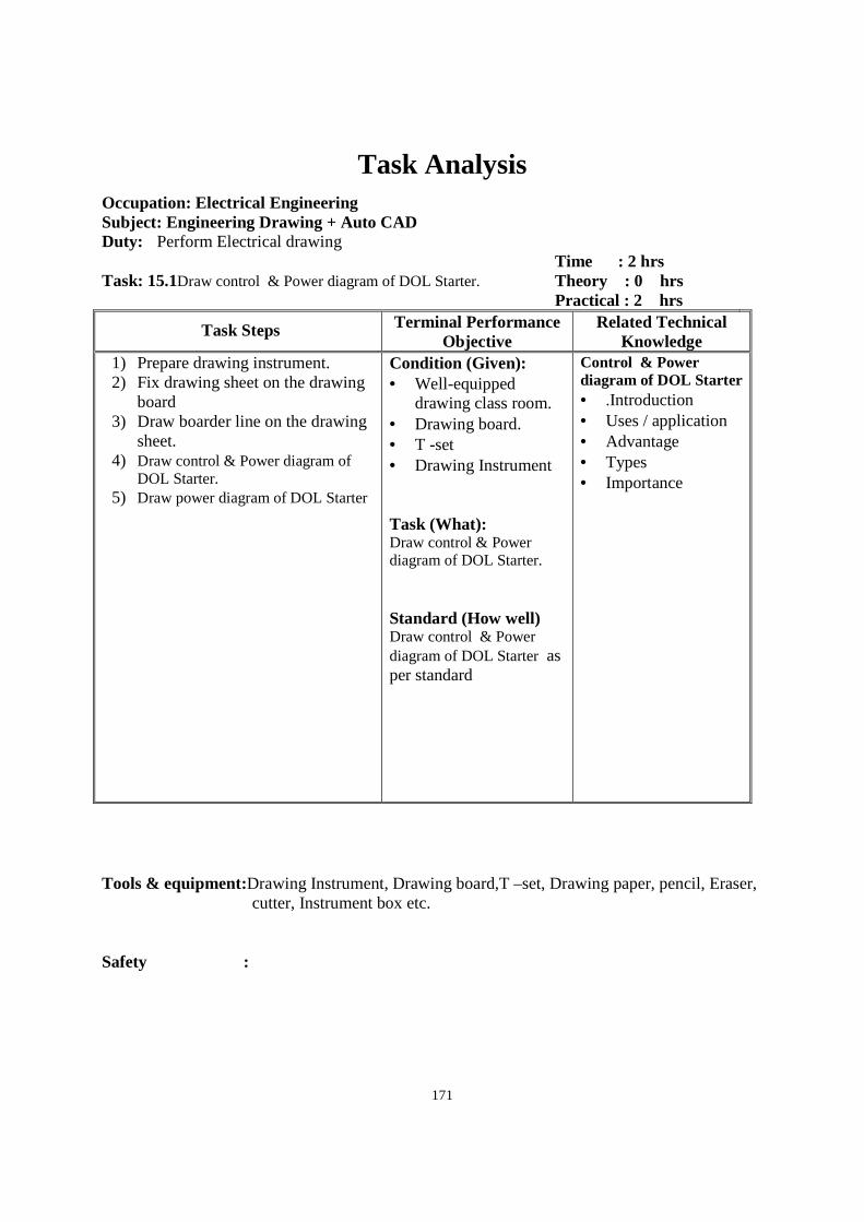
171
Task Analysis
Occupation: Electrical Engineering Subject: Engineering Drawing + Auto CAD Duty: Perform Electrical drawing Task: 15.1Draw control & Power diagram of DOL Starter.
Time : 2 hrs Theory : 0 hrs Practical : 2 hrs
Task Steps Terminal Performance Objective
Related Technical Knowledge
1) Prepare drawing instrument. 2) Fix drawing sheet on the drawing
board 3) Draw boarder line on the drawing
sheet. 4) Draw control & Power diagram of
DOL Starter. 5) Draw power diagram of DOL Starter
Condition (Given): • Well-equipped
drawing class room. • Drawing board. • T -set • Drawing Instrument Task (What): Draw control & Power diagram of DOL Starter. Standard (How well) Draw control & Power diagram of DOL Starter as per standard
Control & Power diagram of DOL Starter • .Introduction • Uses / application • Advantage • Types • Importance
Tools & equipment:Drawing Instrument, Drawing board,T –set, Drawing paper, pencil, Eraser,
cutter, Instrument box etc. Safety :
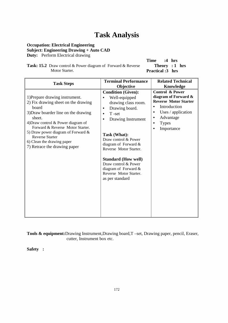
172
Task Analysis
Occupation: Electrical Engineering Subject: Engineering Drawing + Auto CAD Duty: Perform Electrical drawing Task: 15.2 Draw control & Power diagram of Forward & Reverse
Motor Starter.
Time :4 hrs Theory : 1 hrs Practical :3 hrs
Task Steps Terminal Performance Objective
Related Technical Knowledge
1)Prepare drawing instrument. 2) Fix drawing sheet on the drawing
board 3)Draw boarder line on the drawing
sheet. 4)Draw control & Power diagram of
Forward & Reverse Motor Starter. 5) Draw power diagram of Forward &
Reverse Starter 6) Clean the drawing paper 7) Retrace the drawing paper
Condition (Given): • Well-equipped
drawing class room. • Drawing board. • T -set • Drawing Instrument Task (What): Draw control & Power diagram of Forward & Reverse Motor Starter. Standard (How well) Draw control & Power diagram of Forward & Reverse Motor Starter. as per standard
Control & Power diagram of Forward & Reverse Motor Starter • Introduction • Uses / application • Advantage • Types • Importance
Tools & equipment:Drawing Instrument,Drawing board,T –set, Drawing paper, pencil, Eraser,
cutter, Instrument box etc. Safety :
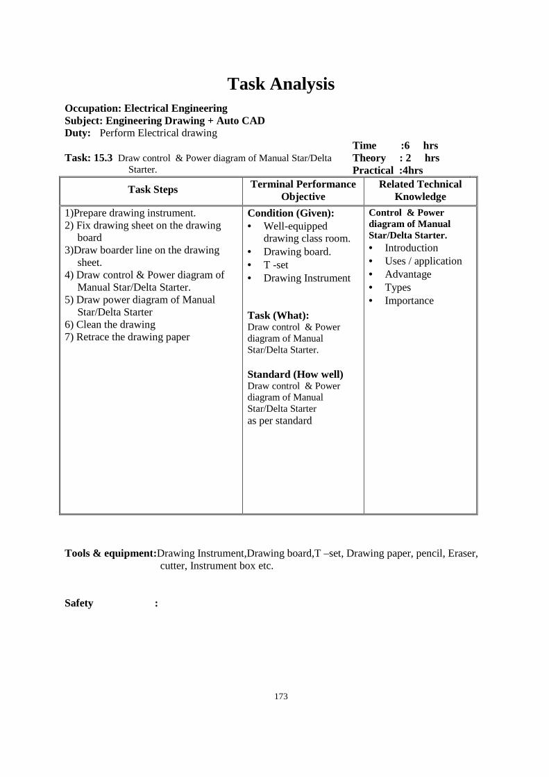
173
Task Analysis
Occupation: Electrical Engineering Subject: Engineering Drawing + Auto CAD Duty: Perform Electrical drawing Task: 15.3 Draw control & Power diagram of Manual Star/Delta
Starter.
Time :6 hrs Theory : 2 hrs Practical :4hrs
Task Steps Terminal Performance Objective
Related Technical Knowledge
1)Prepare drawing instrument. 2) Fix drawing sheet on the drawing
board 3)Draw boarder line on the drawing
sheet. 4) Draw control & Power diagram of
Manual Star/Delta Starter. 5) Draw power diagram of Manual
Star/Delta Starter 6) Clean the drawing 7) Retrace the drawing paper
Condition (Given): • Well-equipped
drawing class room. • Drawing board. • T -set • Drawing Instrument Task (What): Draw control & Power diagram of Manual Star/Delta Starter. Standard (How well) Draw control & Power diagram of Manual Star/Delta Starter as per standard
Control & Power diagram of Manual Star/Delta Starter. • Introduction • Uses / application • Advantage • Types • Importance
Tools & equipment:Drawing Instrument,Drawing board,T –set, Drawing paper, pencil, Eraser,
cutter, Instrument box etc. Safety :
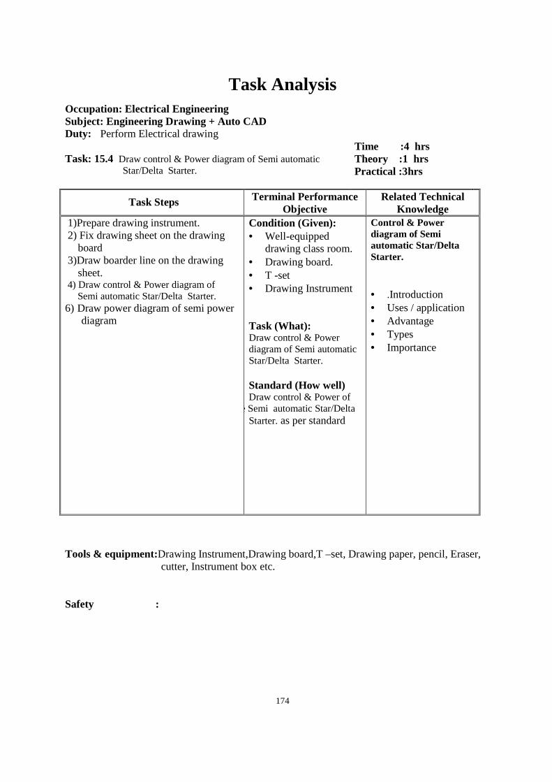
174
Task Analysis
Occupation: Electrical Engineering Subject: Engineering Drawing + Auto CAD Duty: Perform Electrical drawing Task: 15.4 Draw control & Power diagram of Semi automatic
Star/Delta Starter.
Time :4 hrs Theory :1 hrs Practical :3hrs
Task Steps Terminal Performance Objective
Related Technical Knowledge
1)Prepare drawing instrument. 2) Fix drawing sheet on the drawing
board 3)Draw boarder line on the drawing
sheet. 4) Draw control & Power diagram of Semi automatic Star/Delta Starter. 6) Draw power diagram of semi power
diagram
Condition (Given): • Well-equipped
drawing class room. • Drawing board. • T -set • Drawing Instrument Task (What): Draw control & Power diagram of Semi automatic Star/Delta Starter. Standard (How well) Draw control & Power of
diagram of se Semi automatic Star/Delta Starter. as per standard
Control & Power diagram of Semi automatic Star/Delta Starter. • .Introduction • Uses / application • Advantage • Types • Importance
Tools & equipment:Drawing Instrument,Drawing board,T –set, Drawing paper, pencil, Eraser,
cutter, Instrument box etc. Safety :
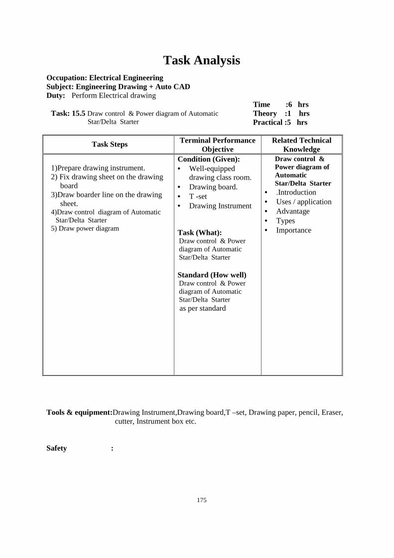
175
Task Analysis
Occupation: Electrical Engineering Subject: Engineering Drawing + Auto CAD Duty: Perform Electrical drawing
Task: 15.5 Draw control & Power diagram of Automatic Star/Delta Starter
Time :6 hrs Theory :1 hrs Practical :5 hrs
Task Steps Terminal Performance Objective
Related Technical Knowledge
1)Prepare drawing instrument. 2) Fix drawing sheet on the drawing
board 3)Draw boarder line on the drawing
sheet. 4)Draw control diagram of Automatic
Star/Delta Starter 5) Draw power diagram
Condition (Given): • Well-equipped
drawing class room. • Drawing board. • T -set • Drawing Instrument Task (What): Draw control & Power diagram of Automatic Star/Delta Starter Standard (How well) Draw control & Power diagram of Automatic Star/Delta Starter as per standard
Draw control & Power diagram of Automatic Star/Delta Starter
• .Introduction • Uses / application • Advantage • Types • Importance
Tools & equipment:Drawing Instrument,Drawing board,T –set, Drawing paper, pencil, Eraser,
cutter, Instrument box etc. Safety :
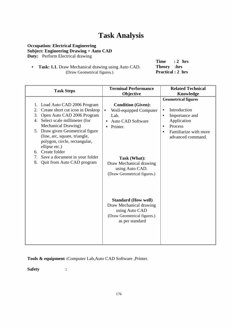
176
Task Analysis
Occupation: Electrical Engineering Subject: Engineering Drawing + Auto CAD Duty: Perform Electrical drawing
• Task: 1.1. Draw Mechanical drawing using Auto CAD.
(Draw Geometrical figures.)
Time : 2 hrs Theory :hrs Practical : 2 hrs
Task Steps Terminal Performance Objective
Related Technical Knowledge
1. Load Auto CAD 2006 Program 2. Create short cut icon in Desktop 3. Open Auto CAD 2006 Program 4. Select scale millimeter (for
Mechanical Drawing) 5. Draw given Geometrical figure
(line, arc, square, triangle, polygon, circle, rectangular, ellipse etc.)
6. Create folder 7. Save a document in your folder 8. Quit from Auto CAD program
Condition (Given):
• Well-equipped Computer Lab.
• Auto CAD Software • Printer.
Task (What): Draw Mechanical drawing
using Auto CAD. (Draw Geometrical figures.)
Standard (How well) Draw Mechanical drawing
using Auto CAD (Draw Geometrical figures.)
as per standard
Geometrical figures • Introduction • Importance and
Application • Process • Familiarize with more
advanced command.
Tools & equipment :Computer Lab,Auto CAD Software ,Printer. Safety :
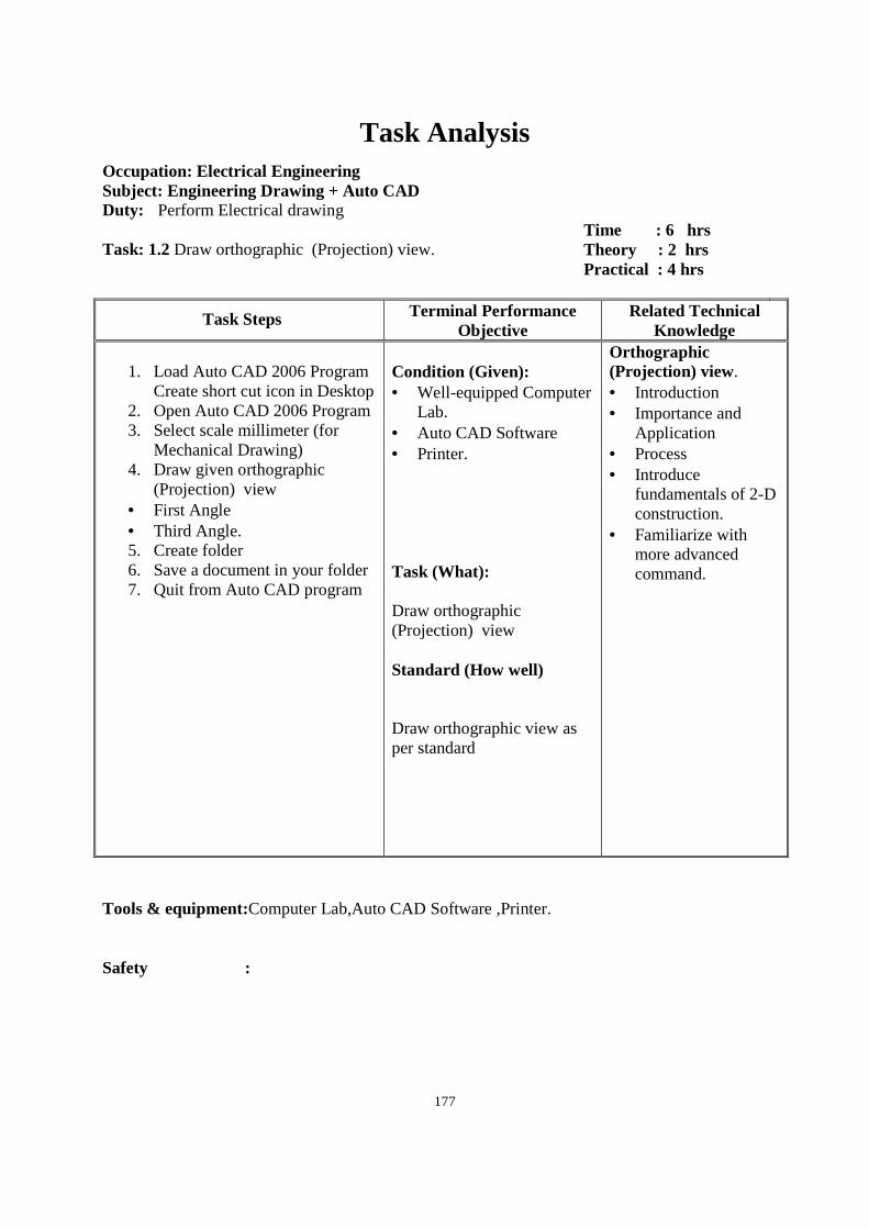
177
Task Analysis
Occupation: Electrical Engineering Subject: Engineering Drawing + Auto CAD Duty: Perform Electrical drawing Task: 1.2 Draw orthographic (Projection) view.
Time : 6 hrs Theory : 2 hrs Practical : 4 hrs
Task Steps Terminal Performance Objective
Related Technical Knowledge
1. Load Auto CAD 2006 Program
Create short cut icon in Desktop 2. Open Auto CAD 2006 Program 3. Select scale millimeter (for
Mechanical Drawing) 4. Draw given orthographic
(Projection) view • First Angle • Third Angle. 5. Create folder 6. Save a document in your folder 7. Quit from Auto CAD program
Condition (Given): • Well-equipped Computer
Lab. • Auto CAD Software • Printer. Task (What): Draw orthographic (Projection) view Standard (How well) Draw orthographic view as per standard
Orthographic (Projection) view. • Introduction • Importance and
Application • Process • Introduce
fundamentals of 2-D construction.
• Familiarize with more advanced command.
Tools & equipment:Computer Lab,Auto CAD Software ,Printer. Safety :
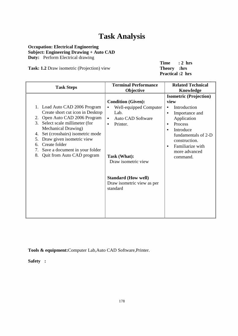
178
Task Analysis
Occupation: Electrical Engineering Subject: Engineering Drawing + Auto CAD Duty: Perform Electrical drawing Task: 1.2 Draw isometric (Projection) view
Time : 2 hrs Theory :hrs Practical :2 hrs
Task Steps Terminal Performance Objective
Related Technical Knowledge
1. Load Auto CAD 2006 Program Create short cut icon in Desktop
2. Open Auto CAD 2006 Program 3. Select scale millimeter (for
Mechanical Drawing) 4. Set (crosshairs) isometric mode 5. Draw given isometric view 6. Create folder 7. Save a document in your folder 8. Quit from Auto CAD program
Condition (Given): • Well-equipped Computer
Lab. • Auto CAD Software • Printer. Task (What): Draw isometric view Standard (How well) Draw isometric view as per standard
Isometric (Projection) view • Introduction • Importance and
Application • Process • Introduce
fundamentals of 2-D construction.
• Familiarize with more advanced command.
Tools & equipment:Computer Lab,Auto CAD Software,Printer. Safety :
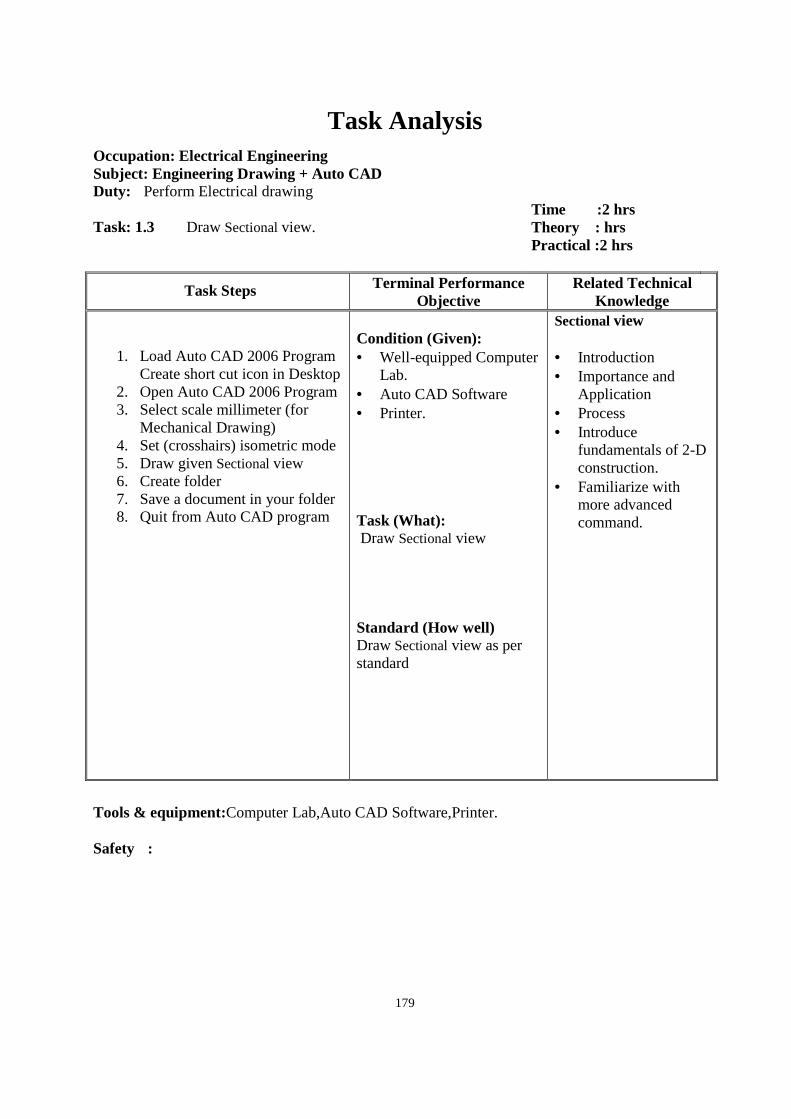
179
Task Analysis
Occupation: Electrical Engineering Subject: Engineering Drawing + Auto CAD Duty: Perform Electrical drawing Task: 1.3 Draw Sectional view.
Time :2 hrs Theory : hrs Practical :2 hrs
Task Steps Terminal Performance Objective
Related Technical Knowledge
1. Load Auto CAD 2006 Program Create short cut icon in Desktop
2. Open Auto CAD 2006 Program 3. Select scale millimeter (for
Mechanical Drawing) 4. Set (crosshairs) isometric mode 5. Draw given Sectional view 6. Create folder 7. Save a document in your folder 8. Quit from Auto CAD program
Condition (Given): • Well-equipped Computer
Lab. • Auto CAD Software • Printer. Task (What): Draw Sectional view Standard (How well) Draw Sectional view as per standard
Sectional view • Introduction • Importance and
Application • Process • Introduce
fundamentals of 2-D construction.
• Familiarize with more advanced command.
Tools & equipment:Computer Lab,Auto CAD Software,Printer. Safety :
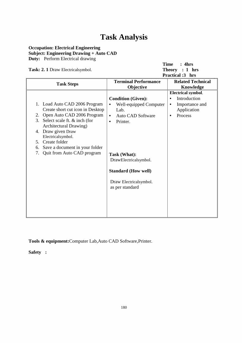
180
Task Analysis
Occupation: Electrical Engineering Subject: Engineering Drawing + Auto CAD Duty: Perform Electrical drawing Task: 2. 1 Draw Electricalsymbol.
Time : 4hrs Theory : 1 hrs Practical :3 hrs
Task Steps Terminal Performance Objective
Related Technical Knowledge
1. Load Auto CAD 2006 Program Create short cut icon in Desktop
2. Open Auto CAD 2006 Program 3. Select scale ft. & inch (for
Architectural Drawing) 4. Draw given Draw
Electricalsymbol. 5. Create folder 6. Save a document in your folder 7. Quit from Auto CAD program
Condition (Given): • Well-equipped Computer
Lab. • Auto CAD Software • Printer. Task (What): DrawElectricalsymbol. Standard (How well) Draw Electricalsymbol. as per standard
Electrical symbol. • Introduction • Importance and
Application • Process
Tools & equipment:Computer Lab,Auto CAD Software,Printer. Safety :
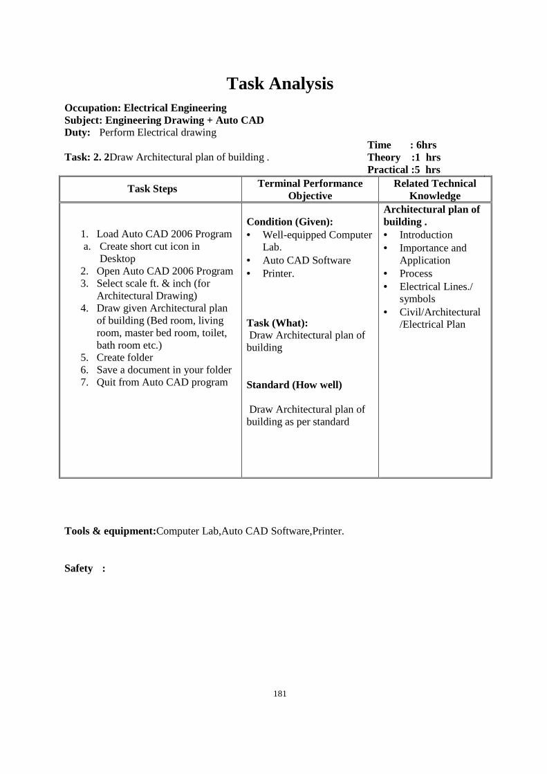
181
Task Analysis
Occupation: Electrical Engineering Subject: Engineering Drawing + Auto CAD Duty: Perform Electrical drawing Task: 2. 2Draw Architectural plan of building .
Time : 6hrs Theory :1 hrs Practical :5 hrs
Task Steps Terminal Performance Objective
Related Technical Knowledge
1. Load Auto CAD 2006 Program a. Create short cut icon in
Desktop 2. Open Auto CAD 2006 Program 3. Select scale ft. & inch (for
Architectural Drawing) 4. Draw given Architectural plan
of building (Bed room, living room, master bed room, toilet, bath room etc.)
5. Create folder 6. Save a document in your folder 7. Quit from Auto CAD program
Condition (Given): • Well-equipped Computer
Lab. • Auto CAD Software • Printer. Task (What): Draw Architectural plan of building Standard (How well) Draw Architectural plan of building as per standard
Architectural plan of building . • Introduction • Importance and
Application • Process • Electrical Lines./
symbols • Civil/Architectural
/Electrical Plan
Tools & equipment:Computer Lab,Auto CAD Software,Printer. Safety :
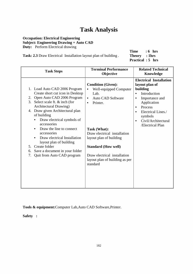
182
Task Analysis
Occupation: Electrical Engineering Subject: Engineering Drawing + Auto CAD Duty: Perform Electrical drawing Task: 2.3 Draw Electrical Installation layout plan of building .
Time : 6 hrs Theory : 1hrs Practical : 5 hrs
Task Steps Terminal Performance Objective
Related Technical Knowledge
1. Load Auto CAD 2006 Program Create short cut icon in Desktop
2. Open Auto CAD 2006 Program 3. Select scale ft. & inch (for
Architectural Drawing) 4. Draw given Architectural plan
of building • Draw electrical symbols of
accessories • Draw the line to connect
accessories • Draw electrical Installation
layout plan of building 5. Create folder 6. Save a document in your folder 7. Quit from Auto CAD program
Condition (Given): • Well-equipped Computer
Lab. • Auto CAD Software • Printer. Task (What): Draw electrical installation layout plan of building Standard (How well) Draw electrical installation layout plan of building as per standard
Electrical Installation layout plan of building • Introduction • Importance and
Application • Process • Electrical Lines./
symbols • Civil/Architectural
/Electrical Plan
Tools & equipment:Computer Lab,Auto CAD Software,Printer. Safety :
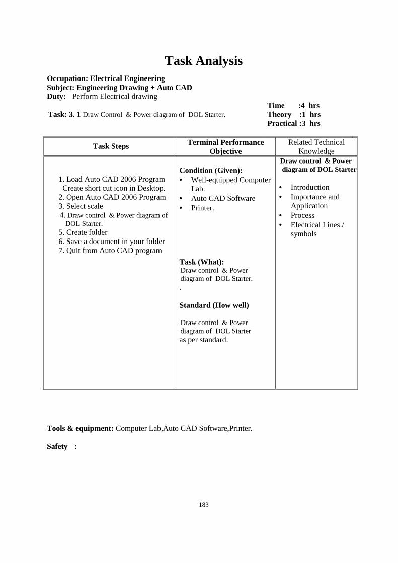
183
Task Analysis
Occupation: Electrical Engineering Subject: Engineering Drawing + Auto CAD Duty: Perform Electrical drawing Task: 3. 1 Draw Control & Power diagram of DOL Starter.
Time :4 hrs Theory :1 hrs Practical :3 hrs
Task Steps Terminal Performance Objective
Related Technical Knowledge
1. Load Auto CAD 2006 Program Create short cut icon in Desktop.
2. Open Auto CAD 2006 Program 3. Select scale
4. Draw control & Power diagram of DOL Starter.
5. Create folder 6. Save a document in your folder 7. Quit from Auto CAD program
Condition (Given): • Well-equipped Computer
Lab. • Auto CAD Software • Printer. Task (What): Draw control & Power diagram of DOL Starter. . Standard (How well) Draw control & Power diagram of DOL Starter as per standard.
Draw control & Power diagram of DOL Starter. • Introduction • Importance and
Application • Process • Electrical Lines./
symbols
Tools & equipment: Computer Lab,Auto CAD Software,Printer. Safety :
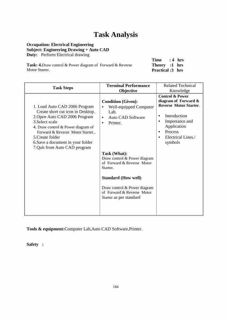
184
Task Analysis
Occupation: Electrical Engineering Subject: Engineering Drawing + Auto CAD Duty: Perform Electrical drawing Task: 4.Draw control & Power diagram of Forward & Reverse Motor Starter.
Time : 4 hrs Theory :1 hrs Practical :3 hrs
Task Steps Terminal Performance Objective
Related Technical Knowledge
1. Load Auto CAD 2006 Program Create short cut icon in Desktop.
2.Open Auto CAD 2006 Program 3.Select scale 4. Draw control & Power diagram of
Forward & Reverse Motor Starter.. 5.Create folder 6.Save a document in your folder 7.Quit from Auto CAD program
Condition (Given): • Well-equipped Computer
Lab. • Auto CAD Software • Printer. Task (What): Draw control & Power diagram of Forward & Reverse Motor Starter. Standard (How well) Draw control & Power diagram of Forward & Reverse Motor Starter as per standard
Control & Power diagram of Forward & Reverse Motor Starter. • Introduction • Importance and
Application • Process • Electrical Lines./
symbols
Tools & equipment:Computer Lab,Auto CAD Software,Printer. Safety :
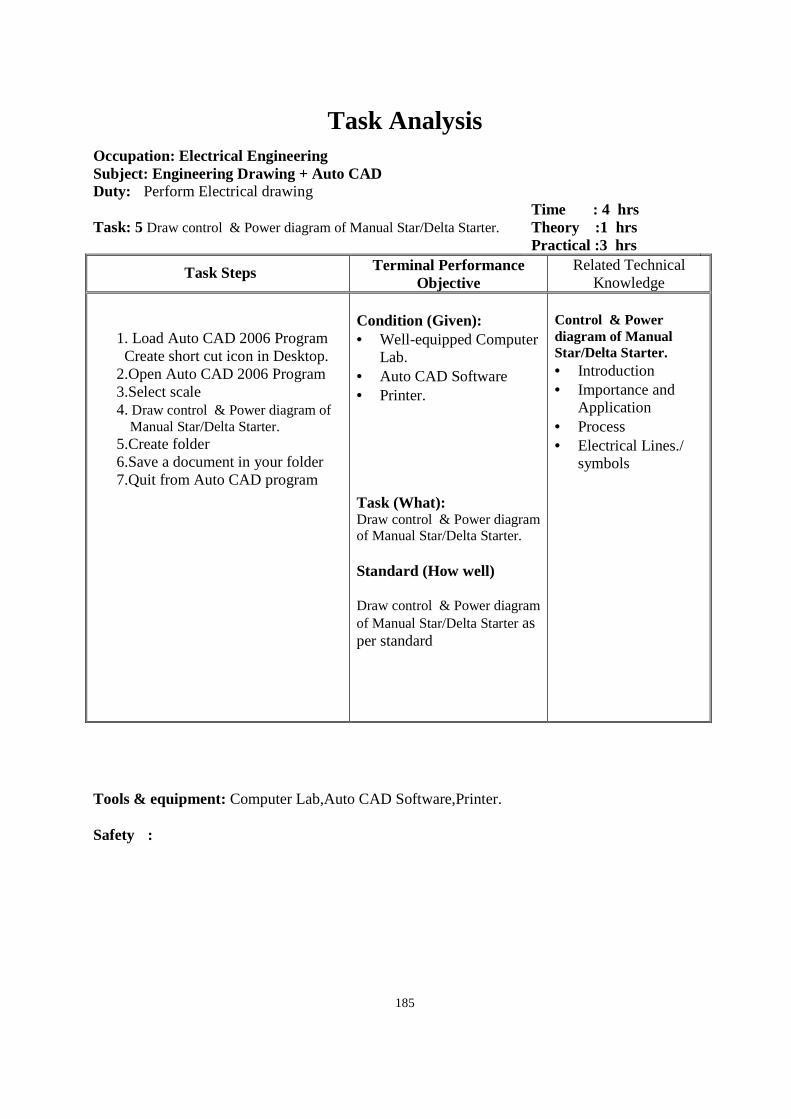
185
Task Analysis
Occupation: Electrical Engineering Subject: Engineering Drawing + Auto CAD Duty: Perform Electrical drawing Task: 5 Draw control & Power diagram of Manual Star/Delta Starter.
Time : 4 hrs Theory :1 hrs Practical :3 hrs
Task Steps Terminal Performance Objective
Related Technical Knowledge
1. Load Auto CAD 2006 Program Create short cut icon in Desktop.
2.Open Auto CAD 2006 Program 3.Select scale 4. Draw control & Power diagram of
Manual Star/Delta Starter. 5.Create folder 6.Save a document in your folder 7.Quit from Auto CAD program
Condition (Given): • Well-equipped Computer
Lab. • Auto CAD Software • Printer. Task (What): Draw control & Power diagram of Manual Star/Delta Starter. Standard (How well) Draw control & Power diagram of Manual Star/Delta Starter as per standard
Control & Power diagram of Manual Star/Delta Starter. • Introduction • Importance and
Application • Process • Electrical Lines./
symbols
Tools & equipment: Computer Lab,Auto CAD Software,Printer. Safety :
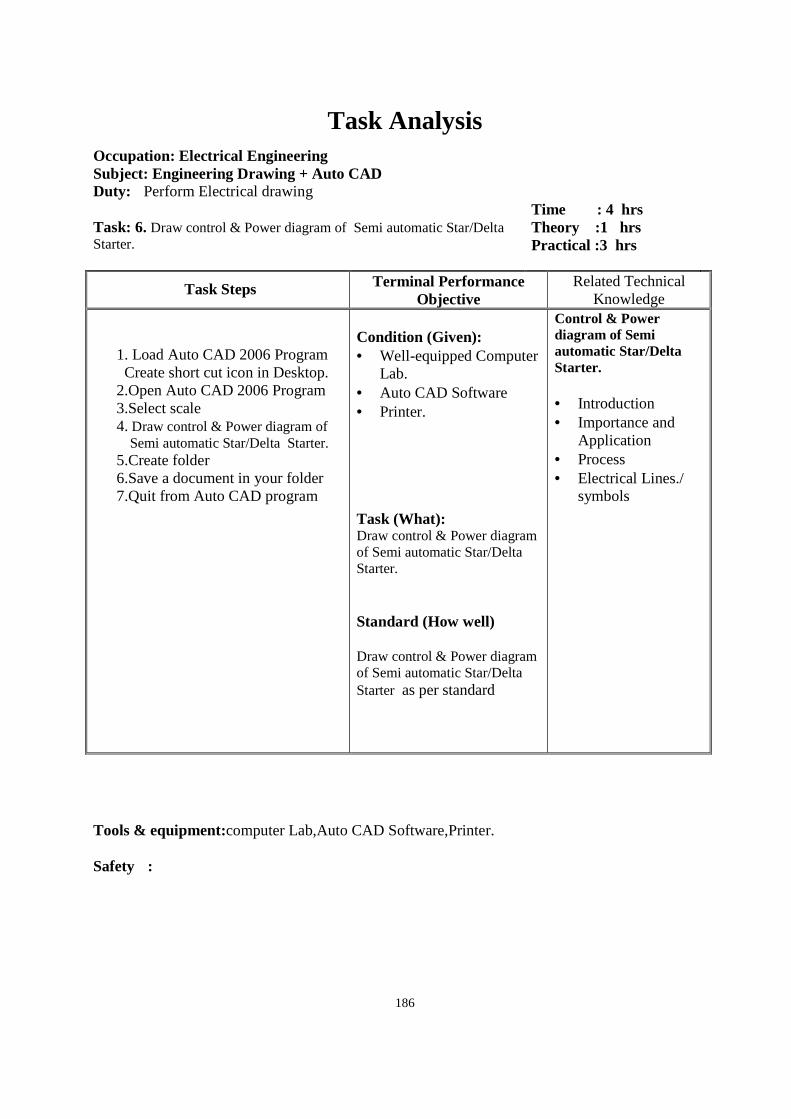
186
Task Analysis
Occupation: Electrical Engineering Subject: Engineering Drawing + Auto CAD Duty: Perform Electrical drawing Task: 6. Draw control & Power diagram of Semi automatic Star/Delta Starter.
Time : 4 hrs Theory :1 hrs Practical :3 hrs
Task Steps Terminal Performance Objective
Related Technical Knowledge
1. Load Auto CAD 2006 Program Create short cut icon in Desktop.
2.Open Auto CAD 2006 Program 3.Select scale
4. Draw control & Power diagram of Semi automatic Star/Delta Starter.
5.Create folder 6.Save a document in your folder 7.Quit from Auto CAD program
Condition (Given): • Well-equipped Computer
Lab. • Auto CAD Software • Printer. Task (What): Draw control & Power diagram of Semi automatic Star/Delta Starter. Standard (How well) Draw control & Power diagram of Semi automatic Star/Delta Starter as per standard
Control & Power diagram of Semi automatic Star/Delta Starter. • Introduction • Importance and
Application • Process • Electrical Lines./
symbols
Tools & equipment:computer Lab,Auto CAD Software,Printer. Safety :
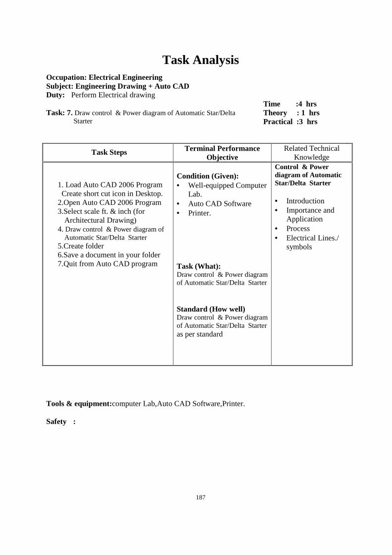
187
Task Analysis
Occupation: Electrical Engineering Subject: Engineering Drawing + Auto CAD Duty: Perform Electrical drawing Task: 7. Draw control & Power diagram of Automatic Star/Delta
Starter
Time :4 hrs Theory : 1 hrs Practical :3 hrs
Task Steps Terminal Performance Objective
Related Technical Knowledge
1. Load Auto CAD 2006 Program Create short cut icon in Desktop.
2.Open Auto CAD 2006 Program 3.Select scale ft. & inch (for
Architectural Drawing) 4. Draw control & Power diagram of
Automatic Star/Delta Starter 5.Create folder 6.Save a document in your folder 7.Quit from Auto CAD program
Condition (Given): • Well-equipped Computer
Lab. • Auto CAD Software • Printer. Task (What): Draw control & Power diagram of Automatic Star/Delta Starter Standard (How well) Draw control & Power diagram of Automatic Star/Delta Starter as per standard
Control & Power diagram of Automatic Star/Delta Starter • Introduction • Importance and
Application • Process • Electrical Lines./
symbols
Tools & equipment:computer Lab,Auto CAD Software,Printer. Safety :
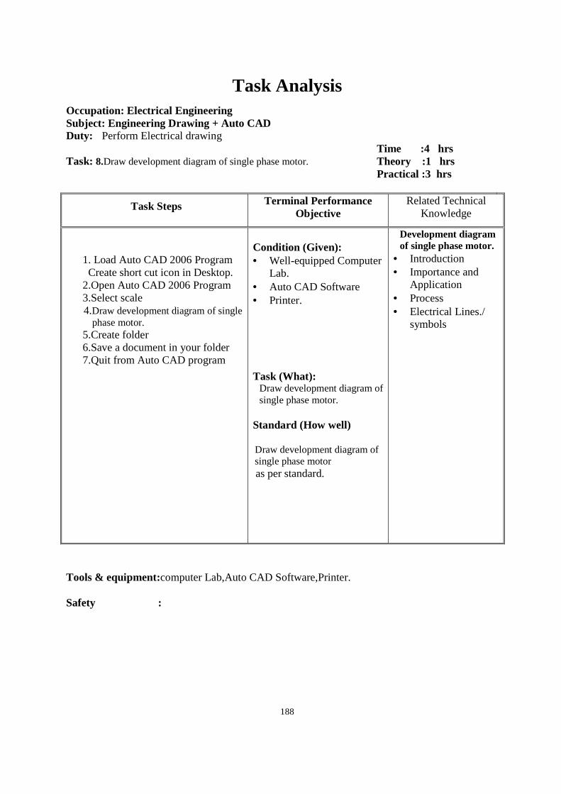
188
Task Analysis
Occupation: Electrical Engineering Subject: Engineering Drawing + Auto CAD Duty: Perform Electrical drawing Task: 8.Draw development diagram of single phase motor.
Time :4 hrs Theory :1 hrs Practical :3 hrs
Task Steps Terminal Performance Objective
Related Technical Knowledge
1. Load Auto CAD 2006 Program Create short cut icon in Desktop.
2.Open Auto CAD 2006 Program 3.Select scale
4.Draw development diagram of single phase motor.
5.Create folder 6.Save a document in your folder 7.Quit from Auto CAD program
Condition (Given): • Well-equipped Computer
Lab. • Auto CAD Software • Printer. Task (What):
Draw development diagram of single phase motor.
Standard (How well) Draw development diagram of single phase motor as per standard.
Development diagram of single phase motor.
• Introduction • Importance and
Application • Process • Electrical Lines./
symbols
Tools & equipment:computer Lab,Auto CAD Software,Printer. Safety :
189
Task Analysis
Occupation: Electrical Engineering Subject: Engineering Drawing + Auto CAD Duty: Perform Electrical drawing Task: 9 Draw development diagram of three phase balance motor.
Time :6 hrs Theory : 1 hrs Practical :5hrs
Task Steps Terminal Performance Objective
Related Technical Knowledge
1. Load Auto CAD 2006 Program Create short cut icon in Desktop.
2.Open Auto CAD 2006 Program 3.Select scale
4. Draw development diagram of three phase balance motor.
5.Create folder 6.Save a document in your folder 7.Quit from Auto CAD program
Condition (Given): • Well-equipped Computer
Lab. • Auto CAD Software • Printer. Task (What): Draw development diagram of three phase balance motor. Standard (How well) Draw development diagram of three phase balance motoras per standard
Development diagram of three phase balance motor. • Introduction • Importance and
Application • Process • Electrical Lines./
symbols
Tools & equipment:Computer Lab,Auto CAD Software,Printer. Safety :
190
Task Analysis
Occupation: Electrical Engineering Subject: Engineering Drawing + Auto CAD Duty: Perform Electrical drawing Task:10.Draw development diagram of three phase unbalance motor.
Time :6 hrs Theory :1hrs Practical :5hrs
Task Steps Terminal Performance Objective
Related Technical Knowledge
1. Load Auto CAD 2006 Program Create short cut icon in Desktop.
2.Open Auto CAD 2006 Program 3.Select scale
4. Draw development diagram of three phase unbalance motor.
5.Create folder 6.Save a document in your folder 7.Quit from Auto CAD program
Condition (Given): • Well-equipped Computer
Lab. • Auto CAD Software • Printer. Task (What): Draw development diagram of three phase unbalance motor. Standard (How well) Draw development diagram of three phase unbalance motoras per standard
Development diagram of three phase unbalance motor. • Introduction • Importance and
Application • Process • Electrical Lines./
symbols
Tools & equipment:Computer Lab,Auto CAD Software ,Printer. Safety :
191
Task Analysis
Occupation: Electrical Engineering Subject: Engineering Drawing + Auto CAD Duty: Perform Electrical drawing Task:11Draw internal connection diagram of Capacitor start 1Φ motor
with protective device.
Time :2 hrs Theory :hrs Practical : 2 hrs
Task Steps Terminal Performance Objective
Related Technical Knowledge
1. Load Auto CAD 2006 Program Create short cut icon in Desktop.
2.Open Auto CAD 2006 Program 3.Select scale
4.Draw internal connection diagram of Capacitor start 1Φ motor with protective device.
5.Create folder 6.Save a document in your folder 7.Quit from Auto CAD program
Condition (Given): • Well-equipped Computer
Lab. • Auto CAD Software • Printer. Task (What): Draw internal connection diagram of Capacitor start 1Φ motor with protective device. Standard (How well) Draw internal connection diagram of Capacitor start 1Φ motor with protective device. as per standard
Internal connection diagram of Capacitor start 1Φ motor with protective device. • Introduction • Importance and
Application • Process • Electrical Lines./
symbols
Tools & equipment:Computer Lab,Auto CAD Software,Printer. Safety :
192
Task Analysis
Occupation: Electrical Engineering Subject: Engineering Drawing + Auto CAD Duty: Perform Electrical drawing Task:12Draw internal connection diagram of Capacitor start capacitor
Run 1Φ motor with protective device.
Time :2 hrs Theory :hrs Practical :2 hrs
Task Steps Terminal Performance Objective
Related Technical Knowledge
1. Load Auto CAD 2006 Program Create short cut icon in Desktop.
2.Open Auto CAD 2006 Program 3.Select scale 4.Draw internal connection diagram of
Capacitor start capacitor Run 1Φ motor with protective device.
5.Create folder 6.Save a document in your folder 7.Quit from Auto CAD program
Condition (Given): • Well-equipped Computer
Lab. • Auto CAD Software • Printer. Task (What): Draw internal connection diagram of Capacitor start capacitor Run 1Φ motor with protective device. Standard (How well) Draw internal connection diagram of Capacitor start capacitor Run 1Φ motor with protective deviceas per standard
Internal connection diagram of Capacitor start capacitor Run 1Φ motor with protective device. • Introduction • Importance and
Application • Process • Electrical Lines./
symbols
Tools & equipment:Computer Lab,Auto CAD Software,Printer. Safety :
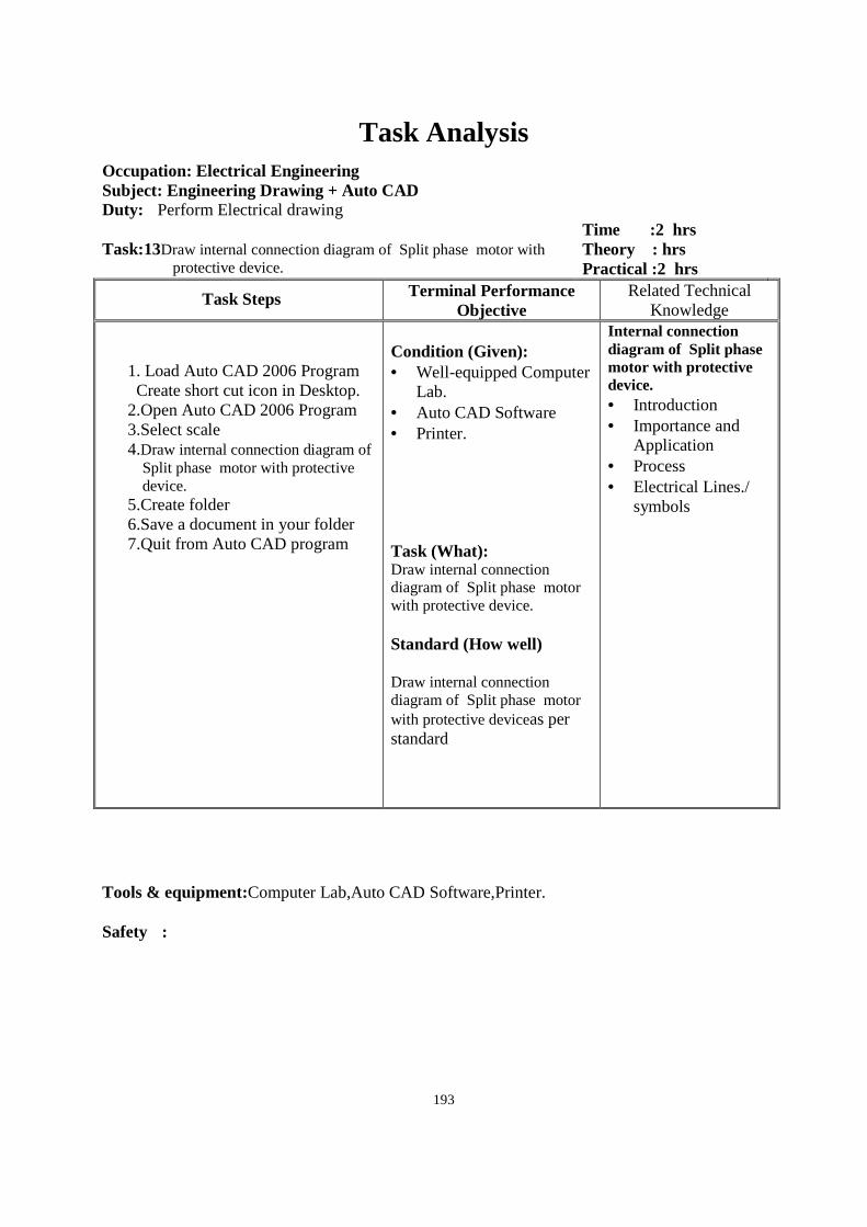
193
Task Analysis
Occupation: Electrical Engineering Subject: Engineering Drawing + Auto CAD Duty: Perform Electrical drawing Task:13Draw internal connection diagram of Split phase motor with
protective device.
Time :2 hrs Theory : hrs Practical :2 hrs
Task Steps Terminal Performance Objective
Related Technical Knowledge
1. Load Auto CAD 2006 Program Create short cut icon in Desktop.
2.Open Auto CAD 2006 Program 3.Select scale 4.Draw internal connection diagram of
Split phase motor with protective device.
5.Create folder 6.Save a document in your folder 7.Quit from Auto CAD program
Condition (Given): • Well-equipped Computer
Lab. • Auto CAD Software • Printer. Task (What): Draw internal connection diagram of Split phase motor with protective device. Standard (How well) Draw internal connection diagram of Split phase motor with protective deviceas per standard
Internal connection diagram of Split phase motor with protective device. • Introduction • Importance and
Application • Process • Electrical Lines./
symbols
Tools & equipment:Computer Lab,Auto CAD Software,Printer. Safety :
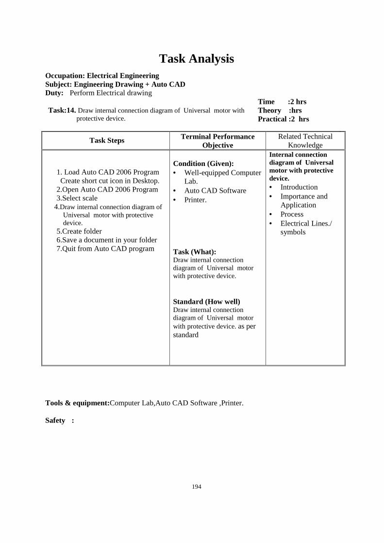
194
Task Analysis
Occupation: Electrical Engineering Subject: Engineering Drawing + Auto CAD Duty: Perform Electrical drawing Task:14. Draw internal connection diagram of Universal motor with
protective device.
Time :2 hrs Theory :hrs Practical :2 hrs
Task Steps Terminal Performance Objective
Related Technical Knowledge
1. Load Auto CAD 2006 Program Create short cut icon in Desktop.
2.Open Auto CAD 2006 Program 3.Select scale
4.Draw internal connection diagram of Universal motor with protective device.
5.Create folder 6.Save a document in your folder 7.Quit from Auto CAD program
Condition (Given): • Well-equipped Computer
Lab. • Auto CAD Software • Printer. Task (What): Draw internal connection diagram of Universal motor with protective device. Standard (How well) Draw internal connection diagram of Universal motor with protective device. as per standard
Internal connection diagram of Universal motor with protective device. • Introduction • Importance and
Application • Process • Electrical Lines./
symbols
Tools & equipment:Computer Lab,Auto CAD Software ,Printer. Safety :

195
Task Analysis
Occupation: Electrical Engineering Subject: Engineering Drawing + Auto CAD Duty: Perform Electrical drawing Task:15Draw internal connection diagram of Permanent Capacitor
motor with protective device.
Time : 2 hrs Theory :hrs Practical :2 hrs
Task Steps Terminal Performance Objective
Related Technical Knowledge
1. Load Auto CAD 2006 Program
Create short cut icon in Desktop. 2.Open Auto CAD 2006 Program 3.Select scale
4.Draw internal connection diagram of Permanent Capacitor motor with protective device.
5.Create folder 6.Save a document in your folder 7.Quit from Auto CAD program
Condition (Given): • Well-equipped Computer
Lab. • Auto CAD Software • Printer. Task (What): Draw internal connection diagram of Permanent Capacitor motor with protective device. . Standard (How well) Draw internal connection diagram of Permanent Capacitor motor with protective device. as per standard
Internal connection diagram of Permanent Capacitor motor with protective device. • Introduction • Importance and
Application • Process • Electrical Lines./
symbols
Tools & equipment:Computer Lab,Auto CAD Software,Printer. Safety :
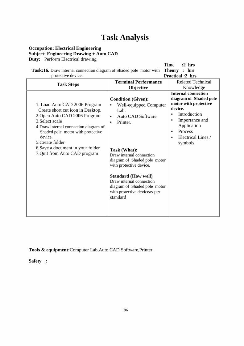
196
Task Analysis
Occupation: Electrical Engineering Subject: Engineering Drawing + Auto CAD Duty: Perform Electrical drawing
Task:16. Draw internal connection diagram of Shaded pole motor with protective device.
Time :2 hrs Theory : hrs Practical :2 hrs
Task Steps Terminal Performance Objective
Related Technical Knowledge
1. Load Auto CAD 2006 Program Create short cut icon in Desktop.
2.Open Auto CAD 2006 Program 3.Select scale 4.Draw internal connection diagram of
Shaded pole motor with protective device.
5.Create folder 6.Save a document in your folder 7.Quit from Auto CAD program
Condition (Given): • Well-equipped Computer
Lab. • Auto CAD Software • Printer. Task (What): Draw internal connection diagram of Shaded pole motor with protective device. Standard (How well) Draw internal connection diagram of Shaded pole motor with protective deviceas per standard
Internal connection diagram of Shaded pole motor with protective device. • Introduction • Importance and
Application • Process • Electrical Lines./
symbols
Tools & equipment:Computer Lab,Auto CAD Software,Printer. Safety :
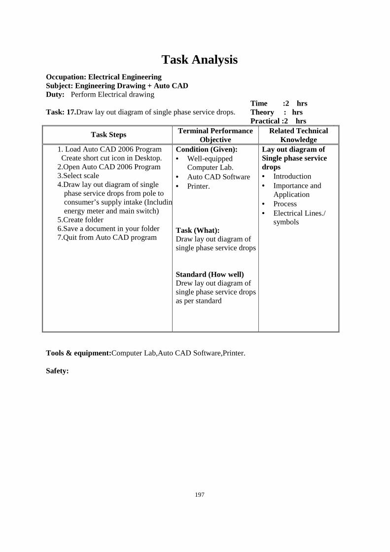
197
Task Analysis
Occupation: Electrical Engineering Subject: Engineering Drawing + Auto CAD Duty: Perform Electrical drawing Task: 17.Draw lay out diagram of single phase service drops.
Time :2 hrs Theory : hrs Practical :2 hrs
Task Steps Terminal Performance Objective
Related Technical Knowledge
1. Load Auto CAD 2006 Program Create short cut icon in Desktop.
2.Open Auto CAD 2006 Program 3.Select scale
4.Draw lay out diagram of single phase service drops from pole to consumer’s supply intake (Including energy meter and main switch)
5.Create folder 6.Save a document in your folder
7.Quit from Auto CAD program
Condition (Given): • Well-equipped
Computer Lab. • Auto CAD Software • Printer. Task (What): Draw lay out diagram of single phase service drops Standard (How well) Drew lay out diagram of single phase service drops as per standard
Lay out diagram of Single phase service drops • Introduction • Importance and
Application • Process • Electrical Lines./
symbols
Tools & equipment:Computer Lab,Auto CAD Software,Printer. Safety:

198
Task Analysis
Occupation: Electrical Engineering Subject: Engineering Drawing + Auto CAD Duty: Perform Electrical drawing Task: 18. Draw lay out diagram of three phase system
Time :2 hrs Theory : hrs Practical :2 hrs
Task Steps Terminal Performance Objective
Related Technical Knowledge
. Load Auto CAD 2006 Program Create short cut icon in Desktop.
2.Open Auto CAD 2006 Program 3.Select scale
4.Draw lay out diagram of three phase service drops from pole to consumer’s supply intake (Including energy meter and main switch)
5.Create folder 6.Save a document in your folder
7.Quit from Auto CAD program
Condition (Given): • Well-equipped
Computer Lab. • Auto CAD Software • Printer. Task (What): Draw lay out diagram of three phase system Standard (How well) Draw lay out diagram of three phase service drops as per standard
Lay out diagram of three phase service drops • Introduction • Importance and
Application • Process • Electrical Lines./
symbols
Tools & equipment:Computer Lab,Auto CAD Software,Printer. Safety :
199
Electrical Engineering II Class/weeks: 2 Hrs Total class/ year:78 Hrs
Unit 1. AC Fundamental
2.1 Definition of AC fundamental
2.2 Importance of AC fundamental
2.3 Electrical terms
2.3.1 Frequency
2.3.2 amplitude
2.3.3 Time period
2.3.4 Average value
2.3.5 RMS value
2.4 AC Sine waves
2.5 Prove V = Vm sin ωt
Unit 2. AC Circuit
3.1 Introduction AC Circuit
3.2 Compare AC and DC circuit
3.3 Define pure AC circuit contain (Resistance, inductance and capacitance) with
phasor and vector diagram
3.4 Familiarize R-L circuit in series with phasor and vector diagram
3.5 Familiarize R-L-C circuit in series with vector diagram
3.6 Familiarize R-L-C circuit in parallel
Unit 3. Three phase circuit
4.1 Definition of three phase circuit
4.2 Compare three phase and single phase circuit
4.3 Importance of three phase circuit
4.4 Define connection of three phase circuit (star 'Y'/ Delta '∆')
4.5 Define line voltage, phase voltage, line current and phase current in star and delta
in three phase and power in phasor diagram.
Unit 4. Power factor correction
5.1 Definition of power factor
5.2 Important of power factor
5.3 Effect of power factor in tariff
200
5.4 Cause of low of power factor
5.5 Disadvantage of low power factor
5.6 Define method of improving power factor
Unit 5. Load factor, demand factor, diversity factor
6.1 Definition of Load factor, Demand factor, Diversity factor
6.2 Important of load factor and demand factor in power system
6.3 Define load curve to determine load factor, demand factor and average load
6.4 Explain reactive power, active power, apparent power
Unit 6. Generation
7.1 Definition of generation of electricity
7.2 Source of generation of electricity
7.3 Importance of generation of electricity
7.4 Define various types of power plants
7.5 Classification of Hydro power
7.6 Familiarize with generation terminology in micro hydro
7.6..1 For bay
7.6..2 Dam cannel
7.6..3 Pen stock
7.6..4 Spill way
7.6..5 Vent pipe
7.6..6 Surge tank
7.6..7 Turbine
7.6..8 Ballast Heater
7.6..9 ELC Board
7.6..10 Synchronization
201
Workshop Technology II
Class / weeks = 2 Period Class / year = 78 Period Unit 1. Survey of domestic and industrial installation
1.1 Introduction 1.2 Layout of wiring 1.3 Co-ordination 1.4 Electrical Installation 1.5 Types of wiring
Unit 2. Basic principle of illumination 2.1 Definition of illumination 2.2 Produced of illumination 2.3 Terminology of illumination (Candle power, Intensity of illumination, Solid angle,
Luminous flux, Lumen) 2.4 Advantage of energy saving lamp 2.5 Describe properties of good illumination 2.6 Describe various types of lamps and tube light luminous flux data. 2.7 Advantage of good illumination 2.8 calculate illumination level
Unit 3. Electrical measuring instrument 3.1 Introduction of Electrical instrument 3.2 Describe classification of Electrical instrument 3.3 Working principle of Moving coil and moving iron instrument 3.4 Construction of moving coil and moving iron instrument 3.5 Application of moving coil instrument 3.6 Properties of moving coil instrument and moving iron instrument 3.7 Compare between moving coil instrument and moving iron instrument
Unit 4. Single phase and three phase distribution system 4.1 Definition of single phase and three phase system and feeder main, transmission
feeder, service main and connection technique from service main 4.2 Describe terms of supply system 4.3 Classification of distribution system 4.4 Describe three phase distribution system
4.4.1 Radial distribution system 4.4.2 Ring distribution system 4.4.3 Grid system
Unit 5. Importance of protective device 5.1 Definition of importance of protective device 5.2 Describe working principle of various type of circuit breaker (i.e. MCCB, MCB,
ELCB, Relay, ACB, OCB etc.) Unit 6. Pre-determinants for location of point
6.1 Location of light point 6.2 Location of power point
6.2.1 Location of control of light 6.2.2 Assessment of load 6.2.3 Definition of main switch/Main distribution board 6.2.4 Types of main switch
202
6.3 (Location of main switch) 6.4 (Definition of sub distribution board) 6.5 (Advantage and disadvantage of main switch) 6.6 (Identification of main switch) 6.7 (Feature of SDB) 6.8 (Sub circuits)
Unit 7. Calculate appropriate size of conductor for different circuit in whole installation. 7.1 Definition of select appropriate copper conductor, aluminum conductor.
7.1.1 Current carrying capacity of conductor 7.2 Size of cable 7.3 Describe voltage drop ± 5% 7.4 (Load center)
7.4.1 cross-sectional area of conductor according to current density 7.4.2 Describe chart of current carrying capacity
7.4.2.1 PVC wire size (1/18, 3/22, 3/20, 7/18, 7/22, 7/20 SWG) 7.4.2.2 (PVC wire size (1, 1.5, 2.5, 4, 6, 10, 16, 25, 35, 50 mm2)
203
Electrical Machine II Class / weeks = 2 Period Class / year = 78 Period
Topic
1. D.C. Generator
2. D.C. motor
3. A.C. 3- phase induction motor.
4. A.C. Generator or Alternator
5. Synchronous motor.
6. A.C. single phase motor
7. Transformer
204
1. D.C. Generator
i. Explain principle of D.C. generator. ii. Describe construction of D.C. generator. iii. Explain types of D.C. generator. iv. Obtain e.m.f. equation of D.C. generator. v. Explain loss that occurs on D.C. generator. vi. Explain about the basic concept of armature reaction. vii. Explain the application of a D.C. generator
2. D.C. motor
i. Explain the principle of D.C. motor. ii. Explain the types of D.C. motor iii. Describe construction of D.C motor. iv. Explain speed control of series, shunt and compound motors. v. Explain the application of series, shunt and compound motors. vi. Obtain e.m.f. equation of a D.C. motor.
3. A.C. 3- phase Induction motor
i. Explain principle of an ac 3-phase induction motor. ii. Explain the construction of stator and rotor of motor. iii. Explain types of Induction motor
4. A.C. Generator (alternator)
i. Explain principles of an alternator. ii. Describe advantage of stationary armature and rotating field. iii. Explain the construction of AC generator. iv. Explain the types of an AC generator. v. Define voltage regulation. vi. Explain the synchronization of an alternator.
5. Synchronous motor
i. Describe the operating principle of synchronous motor. ii. Explain the method of starting of synchronous motor. iii. Explain the advantage of synchronous motor. iv. Compare between synchronous and induction motor. v. Explain the application of synchronous motor
6. A.C. single phase motor
6.1 Explain type of single phase motors. a. Split phase motor b. Capacitor start motor c. Capacitor start capacitor run motor
6.2 Explain the construction of AC single phase motor

205
7. Transformer
8. Explain working principle of transformer. 9. Describe construction of transformer. 10. Explain type of transformer. 11. Derive the e.m.f. equation of a transformer. 12. Explain the voltage regulation in transformer. 13. Describe losses of transformer. 14. Explain the open and short circuit test.
206
Electrical Applied Math II
Class/ week : 3 Hrs Total class/ year :117 Hrs
Unit 1. A.C Fundamental
1.1 Cycle
1.2 Calculate time period
1.3 Calculate frequency
1.4 Average, RMS and Maximum value relation
Unit 2. A.C. Circuit
2.1. Introduction
2.2. Pure resistive circuit
2.3. Pure inductive circuit
2.4. Pure capacitive circuit
2.5. Impedance
2.6. Phase angle
2.7. Power factor
2.8. Series AC Circuit
2.8.1 R-L circuit
2.8.2 R-C circuit
2.8.2 R-L-C circuit
2.9. Active, Reactive and Apparent power in A.C. single phase circuit
Unit 3. Poly-phase circuit
3.1 Introduction of power in three phase star connection
3.2 Power in three phase delta connection
Unit 4. Illumination
4.1 Luminous flux, Intensity
4.2 Illumination.
4.3 Calculation of number of lamps.
4.4 Calculation of simple tarrif
Unit 5. Transformer
5.1 Introduction of input and output voltage and e.m.f. equation
5.2 Number of turns in primary and secondary side
5.3 Transformation ratio
207
5.4 Losses and efficiency
5.5 Voltage regulation.
Unit 6. DC generator
6.1 Generated voltage and terminal voltage
6.2 Armature current and field current
6.3 Copper loss
6.4 Power stages
6.5 Efficiency
Unit 7. DC Motor
7.1 Back e.m.f
7.2 Armature current and field current
7.3 Copper loss
7.4 Power stages
7.5 Efficiency
Unit 8. Synchronous generator
8.1 Phase and line voltage
8.2 Voltage regulation
Unit 9. Synchronous motor
9.1 Synchronous speed
9.2 Back e.m.f
9.3 Mechanical power.
Unit 10. Induction motor
10.1 Synchronous speed
10.2 Back e.m.f.
10.3 Slip
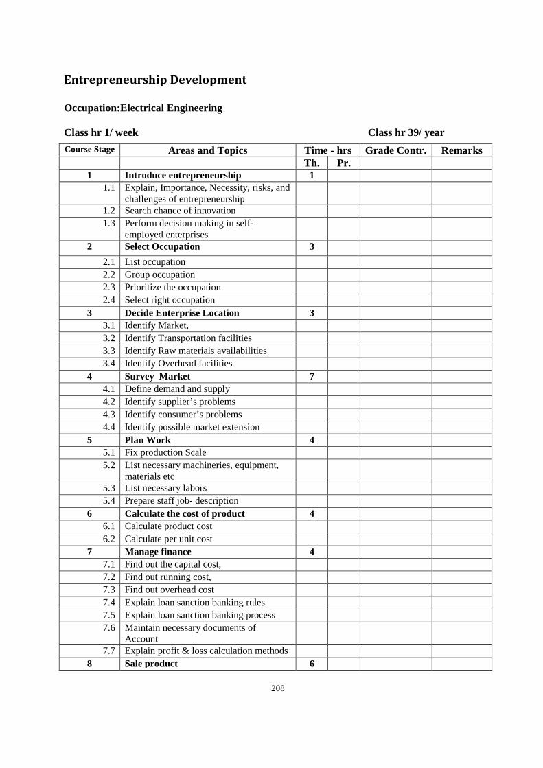
208
Entrepreneurship Development
Occupation:Electrical Engineering Class hr 1/ week Class hr 39/ year
Course Stage Areas and Topics Time - hrs Grade Contr. Remarks Th. Pr. 1 Introduce entrepreneurship 1
1.1 Explain, Importance, Necessity, risks, and challenges of entrepreneurship
1.2 Search chance of innovation 1.3 Perform decision making in self-
employed enterprises
2 Select Occupation 3
2.1 List occupation 2.2 Group occupation 2.3 Prioritize the occupation 2.4 Select right occupation
3 Decide Enterprise Location 3 3.1 Identify Market, 3.2 Identify Transportation facilities 3.3 Identify Raw materials availabilities 3.4 Identify Overhead facilities
4 Survey Market 7 4.1 Define demand and supply 4.2 Identify supplier’s problems 4.3 Identify consumer’s problems 4.4 Identify possible market extension
5 Plan Work 4 5.1 Fix production Scale 5.2 List necessary machineries, equipment,
materials etc
5.3 List necessary labors 5.4 Prepare staff job- description
6 Calculate the cost of product 4 6.1 Calculate product cost 6.2 Calculate per unit cost
7 Manage finance 4 7.1 Find out the capital cost, 7.2 Find out running cost, 7.3 Find out overhead cost 7.4 Explain loan sanction banking rules 7.5 Explain loan sanction banking process 7.6 Maintain necessary documents of
Account
7.7 Explain profit & loss calculation methods 8 Sale product 6
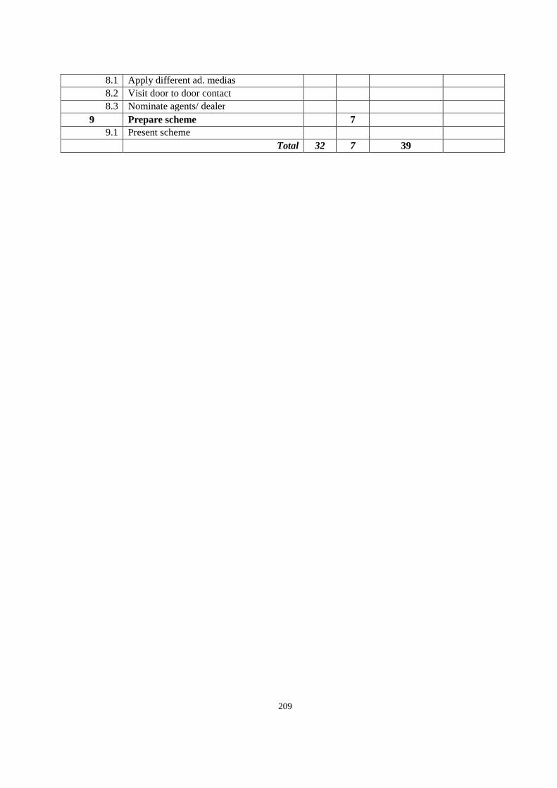
209
8.1 Apply different ad. medias 8.2 Visit door to door contact 8.3 Nominate agents/ dealer
9 Prepare scheme 7 9.1 Present scheme
Total 32 7 39
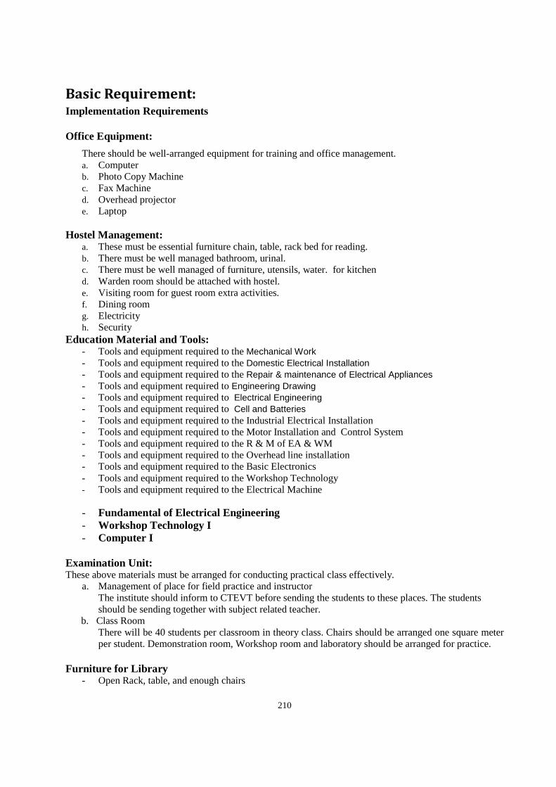
210
Basic Requirement: Implementation Requirements Office Equipment:
There should be well-arranged equipment for training and office management. a. Computer b. Photo Copy Machine c. Fax Machine d. Overhead projector e. Laptop
Hostel Management:
a. These must be essential furniture chain, table, rack bed for reading. b. There must be well managed bathroom, urinal. c. There must be well managed of furniture, utensils, water. for kitchen d. Warden room should be attached with hostel. e. Visiting room for guest room extra activities. f. Dining room g. Electricity h. Security
Education Material and Tools: - Tools and equipment required to the Mechanical Work - Tools and equipment required to the Domestic Electrical Installation - Tools and equipment required to the Repair & maintenance of Electrical Appliances - Tools and equipment required to Engineering Drawing - Tools and equipment required to Electrical Engineering - Tools and equipment required to Cell and Batteries - Tools and equipment required to the Industrial Electrical Installation - Tools and equipment required to the Motor Installation and Control System - Tools and equipment required to the R & M of EA & WM - Tools and equipment required to the Overhead line installation - Tools and equipment required to the Basic Electronics - Tools and equipment required to the Workshop Technology - Tools and equipment required to the Electrical Machine
- Fundamental of Electrical Engineering - Workshop Technology I - Computer I
Examination Unit: These above materials must be arranged for conducting practical class effectively.
a. Management of place for field practice and instructor The institute should inform to CTEVT before sending the students to these places. The students should be sending together with subject related teacher.
b. Class Room There will be 40 students per classroom in theory class. Chairs should be arranged one square meter per student. Demonstration room, Workshop room and laboratory should be arranged for practice.
Furniture for Library
- Open Rack, table, and enough chairs
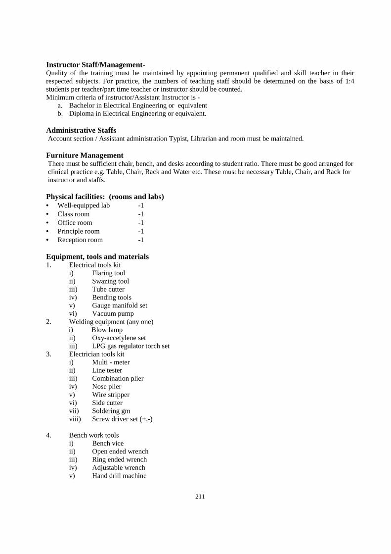
211
Instructor Staff/Management- Quality of the training must be maintained by appointing permanent qualified and skill teacher in their respected subjects. For practice, the numbers of teaching staff should be determined on the basis of 1:4 students per teacher/part time teacher or instructor should be counted. Minimum criteria of instructor/Assistant Instructor is -
a. Bachelor in Electrical Engineering or equivalent b. Diploma in Electrical Engineering or equivalent.
Administrative Staffs Account section / Assistant administration Typist, Librarian and room must be maintained. Furniture Management There must be sufficient chair, bench, and desks according to student ratio. There must be good arranged for clinical practice e.g. Table, Chair, Rack and Water etc. These must be necessary Table, Chair, and Rack for instructor and staffs. Physical facilities: (rooms and labs) • Well-equipped lab -1 • Class room -1 • Office room -1 • Principle room -1 • Reception room -1 Equipment, tools and materials 1. Electrical tools kit
i) Flaring tool ii) Swazing tool iii) Tube cutter iv) Bending tools v) Gauge manifold set vi) Vacuum pump
2. Welding equipment (any one) i) Blow lamp ii) Oxy-accetylene set iii) LPG gas regulator torch set
3. Electrician tools kit i) Multi - meter ii) Line tester iii) Combination plier iv) Nose plier v) Wire stripper vi) Side cutter vii) Soldering gm viii) Screw driver set (+,-)
4. Bench work tools
i) Bench vice ii) Open ended wrench iii) Ring ended wrench iv) Adjustable wrench v) Hand drill machine
212
vi) Hack saw vii) Mini hack saw viii) Allen - key ix) Ball pin hammer x) Mallet hammer xi) Files set xii) Chisel xiii) Center punch xiv) Snip xv) Measuring tape of ruler xvi) Leveling instrument
Materials 1. Electrical materials
i) Copper tubes ( 1/4"Ǿ, 3/8"Ǿ, 5/16"Ǿ etc.) ii) Flare fittings (Union, Tee, elbows, reducers etc.) iii) Sweat (copper) fittings (sockets, Tee, elbows, reducers etc.) iv) Brazing rod v) Refrigerants vi) Refrigeration oil vii) Kerosene oil or carbide & oxygen cylinder of LPG cylinder viii) Insulation material ix) Brazing flux
2. Electrical materials i) PVC tape ii) Soldering lead iii) Cable crimps and fastener iv) Relays v) OHPS vi) Capacitors vii) Heating coils viii) Timer ix) Door switch x) Cabinet bulb xi) Wires & cables xii) Soldering flux
3. Bench work materials i) Screws ii) Nut & bolts iii) Emery papers