Embed Size (px)
Citation preview
42100 Reggio Emilia (Italy)1, Via Natta (Z.I. Mancasale)
Tel. (+39) 0522.50.58Fax. (+39) 0522.50.58.56
Web pages www.aron.itE-mail: [email protected]
File: E11ETA
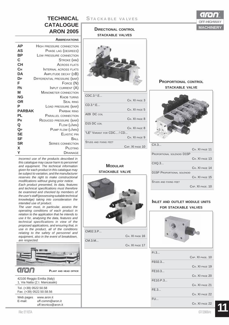
TECHNICALCATALOGUE
ARON 2005ABBREVIATIONS
AP HIGH PRESSURE CONNECTION
AS PHASE LAG (DEGREES)BP LOW PRESSURE CONNECTION
C STROKE (MM)CH ACROSS FLATS
CH INTERNAL ACROSS FLATS
DA AMPLITUDE DECAY (DB)DP DIFFERENTIAL PRESSURE (BAR)F FORCE (N)I% INPUT CURRENT (A)M MANOMETER CONNECTION
NG KNOB TURNS
OR SEAL RING
P LOAD PRESSURE (BAR)PARBAK PARBAK RING
PL PARALLEL CONNECTION
PR REDUCED PRESSURE (BAR)Q FLOW (L/MIN)QP PUMP FLOW (L/MIN)SE ELASTIC PIN
SF BALL
SR SERIES CONNECTION
X PILOTING
Y DRAINAGE
Incorrect use of the products described inthis catalogue may cause harm to personneland equipment. The technical informationgiven for each product in this catalogue maybe subject to variation, and the manufacturerreserves the right to make constructionalmodifications without giving prior notice.Each product presented, its data, featuresand technical specifications must thereforebe examined and checked by members ofthe user's staff (possessing suitable technicalknowledge) taking into consideration theintended use of product.The user must, in particular, assess theoperating conditions of each product inrelation to the application that he intends touse it for, analysing the data, features andtechnical specifications in view of theproposed applications, and ensuring that, inuse in the product, all of the conditionsrelating to the safety of personnel andequipment, also in the event of breakdown,are respected.
PLANT AND HEAD OFFICE
07/2000/e
STACKABLE VALVES
11
DIRECTIONAL CONTROL
STACKABLE VALVES
PROPORTIONAL CONTROL
STACKABLE VALVE
INLET AND OUTLET MODULE UNITS
FOR STACKABLE VALVES
MODULAR
STACKABLE VALVE
CDC.3.*.E...
CH. XI PAGE 3
CD.3.*.E...
CH. XI PAGE 5
A09 DC COIL
CH. XI PAGE 8
D15 DC COIL
CH. XI PAGE 8
"LE" VARIANT FOR CDC... / CD...
CH. XI PAGE 9
STUDS AND FIXING FEET
CAP. XI PAGE 10CX.3...
CH. XI PAGE 11
PROPORTIONAL SOLENOID D15P
CH. XI PAGE 13
CXQ.3...
CH. XI PAGE 14
D15P PROPORTIONAL SOLENOID
CH. XI PAGE 15
STUDS AND FIXING FEET
CAP. XI PAGE. 10
CM02.3.P...
CH. XI PAGE 16
CM.3.M...
CH. XI PAGE 17
FI.3...
CAP. XI PAGE. 10
FE02.3...
CH. XI PAGE 19
FE10.3...
CH. XI PAGE 20
FE10.P.3...
CH. XI PAGE 21
FE.3...
CH. XI PAGE 22
FU...
CH. XI PAGE 22
OFF-HIGHWAY
MACHINERY
11 File: ECDC3001 05/2001/eXI • 2
OFF-HIGHWAY
MACHINERY
TAB.5 - VARIANTS TABLE
TAB.1 - BODY TYPE
L 12VM 24VN 48V*P 110V*Z 102V*X 205V*W Without DC coils
* Special voltage
VARIANT CODE
No variant 00Viton V1Emergency button E1Rotary emergency button P1Solenoid valve without connectors S1First element for series connection PTPilot light X1Rectifier R1Viton + Pilot light VXViton + Rectifier VRPilot light + Rectifier XRcoils with flying leads (length 250 mm) FLcoils with flying leads (length 130 mm)and integrated diode LDAMP Junior connection AJDeutsch connection and bidr. diode CX
Other variants relate to a special design
115Vac/50Hz120Vac/60Hzwith rectifier
230Vac/50Hz240Vac/60Hzwith rectifier
CDC Directional controlstackable valve
3 Size
* Body type (tab. 1)
E Electrical operator
** Spool (tab.2)For series connectionuse spool 04 only
* Mounting (tab.3)
* Voltage (tab.4)
** Variants (tab.5)
1 Serial No.
A Ports G3/8" parallel
B Ports 9/16 - 18UNF parallel
D* Ports G3/8" series
E* Ports 9/16 - 18UNF series
G Attachment style, parallelpresetting for modular valves
H* Attachment style, seriespresetting for modular valves
(*) For series connection configurationsee note below ordering code
TAB.2 - STANDARD SPOOLS
TWO SOLENOIDS,SPRING CENTRED "C" MOUNTING
Spool Covering Transient position
type
01 +
02 -
03 +
04* -
ONE SOLENOID, SIDE A "E" MOUNTING
Spool Covering Transient position
type
01 +
02 -
03 +
04* -
15 -
16 +
ONE SOLENOID, SIDE B "F" MOUNTING
Spool Covering Transient position
type
01 +
02 -
03 +
04* -
15 -
16 +
Max. pressure ports P/A/B/T 250 barMax flow 30 l/minMax excitation frequency 3 HzDuty cycle 100% EDFluid viscosity 10 ÷ 500 mm2/sFluid temperature -25°C ÷ 75°CAmbient temperature -25°C ÷ 60°CMax contamination level class 10 in accordance
with NAS 1638 with filter ß25≥75Weight with one DC solenoid 1,25 KgWeight with two DC solenoids 1,5 Kg
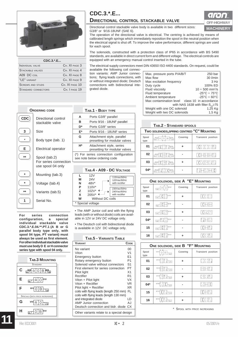
ORDERING CODE
For series connectionconfiguration, a specialindividual stackable valveCDC.3.*.E.04.**.PT.1 (A B or Gparallel body type only, withspool 04 type, PT variant) mustalways be used as first element.For other individual stackable valvemust use body D E or H connectorseries type with spool 04 only.
CDC.3.*.E...DIRECTIONAL CONTROL STACKABLE VALVE
* SPOOL WITH PRICE INCREASING
CDC.3.*.E...
INDIVIDUAL VALVE CH. XI PAGE 3
STACKABLE VALVES CH. XI PAGE 4
A09 DC COIL CH. XI PAGE 8
"LE" VARIANT CH. XI PAGE 9
SCREWS AND STUDS CH. XI PAGE 10
STANDARD CONNECTORS CH. I PAGE 19
TAB.3 MOUNTING
STANDARD
C
E
F
SPECIALS (WITH PRICE INCREASING)
G
H
Directional control stackable valve body is available in two different sizes:G3/8" or 9/16-18UNF (SAE 6).The operation of the directional valve is electrical. The centring is achieved by means ofcalibrated length springs which immediately reposition the spool in the neutral position whenthe electrical signal is shut off. To improve the valve performance, different springs are usedfor each spool.
The solenoids, constructed with a protection class of IP65 in accordance with BS 5490standards, are available in direct current form and different voltage. The electrical controls areequipped with an emergency manual control inserted in the tube.
The electrical supply connectors meet DIN 43650 ISO 4400 standards. On request, could beavailable the following coil connec-tion variants: AMP Junior connec-tions; flying leads connections, withor without integrated diode; Deutschconnections with bidirectional inte-grated diode.
TAB.4 - A09 - DC VOLTAGE
• The AMP Junior coil and with the flyingleads (with or without diode) coils are avail-able in 12V or 24V DC voltage only.
• The Deutsch coil with bidirectional diodeis available in 12V DC voltage only.
11File: ECDC3001 05 /2001/eXI • 3
OFF-HIGHWAY
MACHINERY
P (
bar)
Q (l/min)
1
2
3
4
∆p (
bar)
Q (l/min)
1
2
34
567
8
9
10
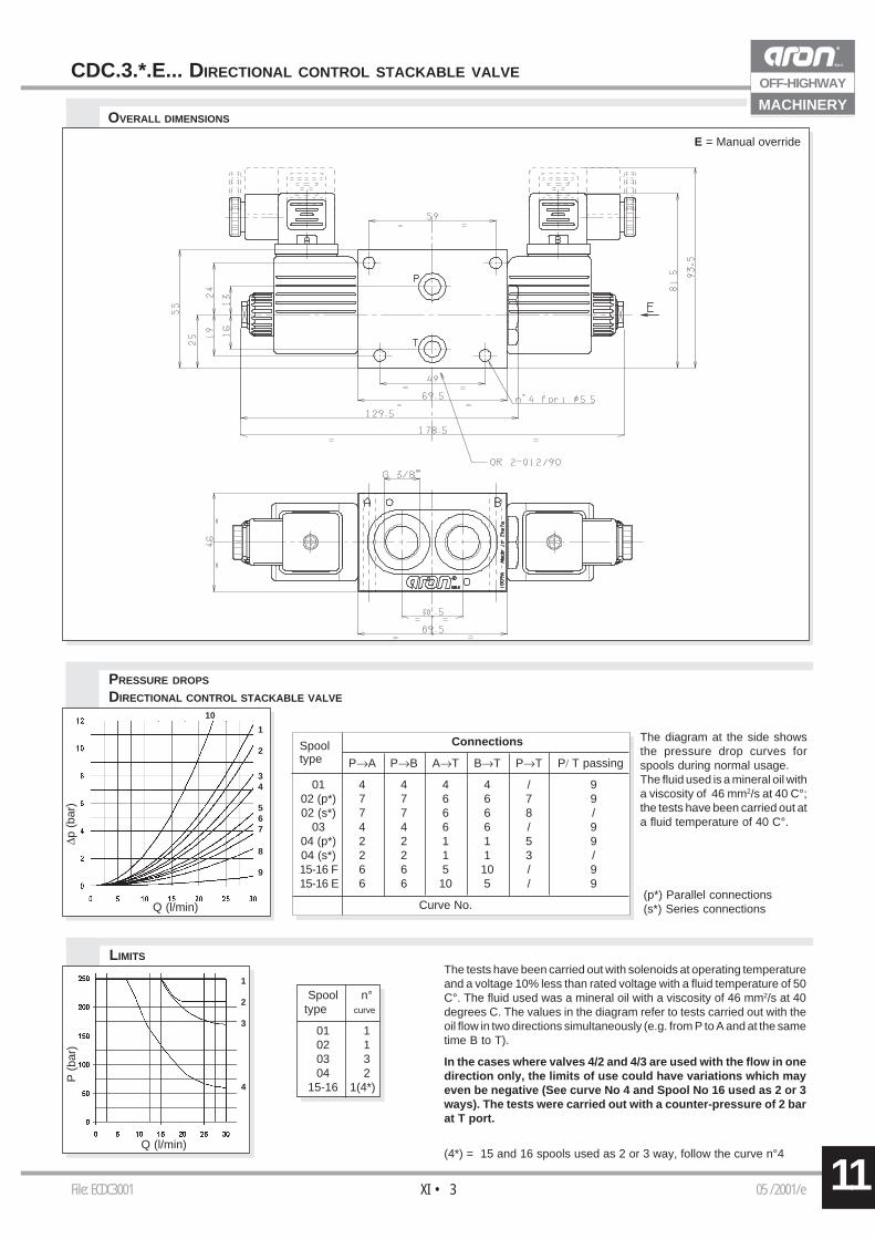
CDC.3.*.E... DIRECTIONAL CONTROL STACKABLE VALVE
OVERALL DIMENSIONS
E = Manual override
PRESSURE DROPS
DIRECTIONAL CONTROL STACKABLE VALVE
The diagram at the side showsthe pressure drop curves forspools during normal usage.The fluid used is a mineral oil witha viscosity of 46 mm2/s at 40 C°;the tests have been carried out ata fluid temperature of 40 C°.
LIMITSThe tests have been carried out with solenoids at operating temperatureand a voltage 10% less than rated voltage with a fluid temperature of 50C°. The fluid used was a mineral oil with a viscosity of 46 mm2/s at 40degrees C. The values in the diagram refer to tests carried out with theoil flow in two directions simultaneously (e.g. from P to A and at the sametime B to T).
In the cases where valves 4/2 and 4/3 are used with the flow in onedirection only, the limits of use could have variations which mayeven be negative (See curve No 4 and Spool No 16 used as 2 or 3ways). The tests were carried out with a counter-pressure of 2 barat T port.
Spool n°type curve
01 102 103 304 2
15-16 1(4*)
(p*) Parallel connections(s*) Series connections
Spool Connectionstype P→A P→B A→T B→T P→T P/ T passing
01 4 4 4 4 / 902 (p*) 7 7 6 6 7 902 (s*) 7 7 6 6 8 /
03 4 4 6 6 / 904 (p*) 2 2 1 1 5 904 (s*) 2 2 1 1 3 /15-16 F 6 6 5 10 / 915-16 E 6 6 10 5 / 9
Curve No.
(4*) = 15 and 16 spools used as 2 or 3 way, follow the curve n°4
11 File: ECDC3001 05/2001/eXI • 4
OFF-HIGHWAY
MACHINERY
STACKABLE DIRECTIONAL CONTROL VALVES
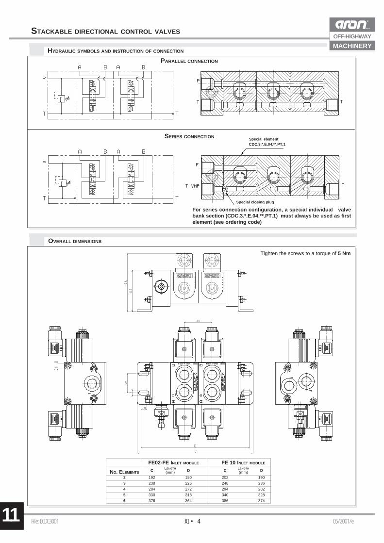
OVERALL DIMENSIONS
HYDRAULIC SYMBOLS AND INSTRUCTION OF CONNECTION
SERIES CONNECTION
PARALLEL CONNECTION
FE02-FE INLET MODULE FE 10 INLET MODULELENGTH LENGTH
NO. ELEMENTS C (mm) D C (mm) D
2 192 180 202 190
3 238 226 248 236
4 284 272 294 282
5 330 318 340 328
6 376 364 386 374
For series connection configuration, a special individual valvebank section (CDC.3.*.E.04.**.PT.1) must always be used as firstelement (see ordering code)
Special elementCDC.3.*.E.04.**.PT.1
Special closing plug
Tighten the screws to a torque of 5 Nm
11File: ECD3001 04/2002/eXI • 5
OFF-HIGHWAY
MACHINERY
TAB.4 - D15 COIL (DC - 30W)
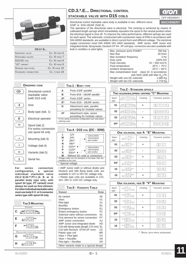
CD.3.*.E... DIRECTIONAL CONTROL
STACKABLE VALVE WITH D15 COILS
Directional control stackable valve body is available in two different sizes:G3/8" or 9/16-18UNF (SAE 6).The operation of the directional valve is electrical. The centring is achieved by means ofcalibrated length springs which immediately reposition the spool in the neutral position whenthe electrical signal is shut off. To improve the valve performance, different springs are usedfor each spool. The solenoids, constructed with a protection class of IP66 in accordance withDIN 40050 standards, are available in direct current form and different voltage. The electricalsupply connectors meet DIN 43650 ISO 4400 standards; AMP Junior, AMP Junior andintegrated diode, flying leads, Deutsch DT 04 - 2P coil type, connectors are also available withbuilt in rectifiers or pilot lights.CD.3.*.E...
INDIVIDUAL VALVE CH. XI PAGE 6
STACKABLE VALVES CH. XI PAGE 7
D15 DC COIL CH. XI PAGE 8
"LE" VARIANT CH. XI PAGE 9
SCREWS AND STUDS CH. XI PAGE 10
STANDARD CONNECTORS CH. I PAGE 19
CD Directional controlstackable valve(with D15 coil)
3 Size
* Body type (tab. 1)
E Electrical operator
** Spool (tab.2)For series connectionuse spool 04 only
* Mounting (tab.3)
* Voltage (tab.4)
** Variants (tab.5)
1 Serial No.
TAB.5 - VARIANTS TABLE
TAB.1 - BODY TYPE
VARIANT CODE
No variant 00Viton V1Pilot light X1Rectifier R1Emergency button E1Rotary emergency button P1Solenoid valve without connectors S1First element for series connection PTAMP Junior connection AJAMP Junior and integrated diode ADCoil with flying leads (length 175 mm) SLCoil with Deutsch DT04-2P conn. CZPalstic type coil BRViton + Pilot light VXViton + Rectifier VRPilot light + Rectifier XR
Other variants relate to a special design
A Ports G3/8" parallel
B Ports 9/16 - 18UNF parallel
D* Ports G3/8" series
E* Ports 9/16 - 18UNF series
G Attachment style, parallelpresetting for modular valves
H* Attachment style, seriespresetting for modular valves
(*) For series connection configuration see note belowordering code
TAB.2 - STANDARD SPOOLS
TWO SOLENOIDS,SPRING CENTRED "C" MOUNTING
Spool Covering Transient position
type
01 +
02 -
03 +
04* -
ONE SOLENOID, SIDE A "E" MOUNTING
Spool Covering Transient position
type
01 +
02 -
03 +
04* -
15 -
16 +
ONE SOLENOID, SIDE B "F" MOUNTING
Spool Covering Transient position
type
01 +
02 -
03 +
04* -
15 -
16 +
ORDERING CODE
For series connectionconfiguration, a specialindividual stackable valveCD.3.*.E.04.**.PT.1 (A B or Gparallel body type only, withspool 04 type, PT variant) mustalways be used as first element.For other individual stackable valvemust use body D E or H connectorseries type with spool 04 only.
TAB.3 MOUNTING
STANDARD
C
E
F
SPECIALS (WITH PRICE INCREASING)
G
H
* SPOOL WITH PRICE INCREASING
* Special voltage
L 12VM 24VV 28V*N 48V*Z 102V*P 110V*X 205V*W Without DC coils or connectors
Voltage codes are not stamped on the plate, their arereadable on the coils.
115Vac/50Hz120Vac/60Hzwith rectifier
230Vac/50Hz240Vac/60Hzwith rectifier
• AMP Junior (with or without diode) andDeutsch and with flying leads coils, areavailable in 12V or 24V DC voltage only.• Plastic type coils are available in 12V,24V, 28V or 110V DC voltage only.
Max. pressure ports P/A/B/T 250 barMax flow 40 l/minMax excitation frequency 3 HzDuty cycle 100% EDFluid viscosity 10 ÷ 500 mm2/sFluid temperature -25°C ÷ 75°CAmbient temperature -25°C ÷ 60°CMax contamination level class 10 in accordance
with NAS 1638 with filter ß25≥75Weight with one DC solenoid 1,389 KgWeight with two DC solenoids 1,778 Kg
11 File: ECD3001 04/2002/eXI • 6
OFF-HIGHWAY
MACHINERY
P (
bar)
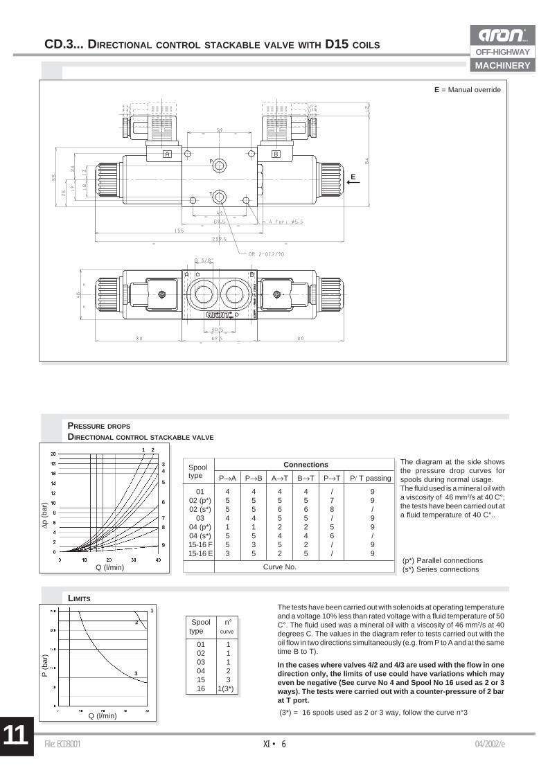
Q (l/min) (3*) = 16 spools used as 2 or 3 way, follow the curve n°3
Spool n°type curve
01 102 103 104 215 316 1(3*)
CD.3... DIRECTIONAL CONTROL STACKABLE VALVE WITH D15 COILS
Spool Connectionstype P→A P→B A→T B→T P→T P/ T passing
01 4 4 4 4 / 902 (p*) 5 5 5 5 7 902 (s*) 5 5 6 6 8 /
03 4 4 5 5 / 904 (p*) 1 1 2 2 5 904 (s*) 5 5 4 4 6 /15-16 F 5 3 5 2 / 915-16 E 3 5 2 5 / 9
Curve No.
∆p (
bar)
Q (l/min)
34
5
6
7
8
9
3
1 2
1
2
PRESSURE DROPS
DIRECTIONAL CONTROL STACKABLE VALVE
The diagram at the side showsthe pressure drop curves forspools during normal usage.The fluid used is a mineral oil witha viscosity of 46 mm2/s at 40 C°;the tests have been carried out ata fluid temperature of 40 C°..
LIMITSThe tests have been carried out with solenoids at operating temperatureand a voltage 10% less than rated voltage with a fluid temperature of 50C°. The fluid used was a mineral oil with a viscosity of 46 mm2/s at 40degrees C. The values in the diagram refer to tests carried out with theoil flow in two directions simultaneously (e.g. from P to A and at the sametime B to T).
In the cases where valves 4/2 and 4/3 are used with the flow in onedirection only, the limits of use could have variations which mayeven be negative (See curve No 4 and Spool No 16 used as 2 or 3ways). The tests were carried out with a counter-pressure of 2 barat T port.
(p*) Parallel connections(s*) Series connections
E = Manual override
E
11File: ECD3001 04/2002/eXI • 7
OFF-HIGHWAY
MACHINERY
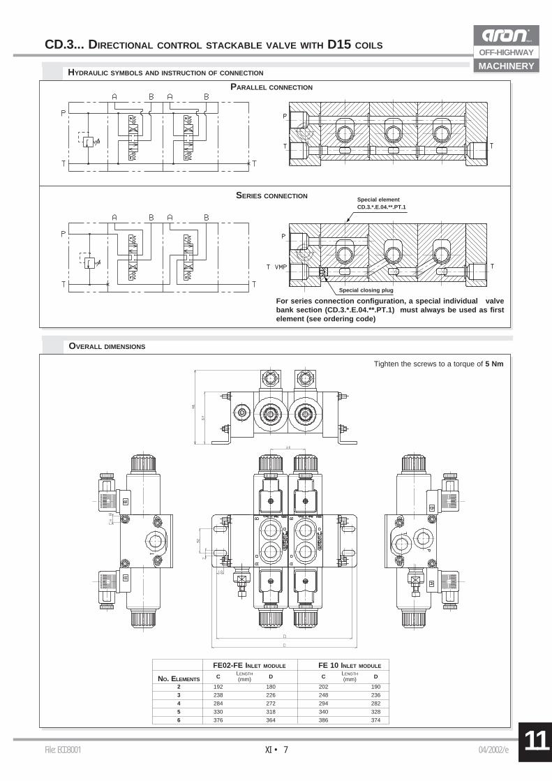
CD.3... DIRECTIONAL CONTROL STACKABLE VALVE WITH D15 COILS
FE02-FE INLET MODULE FE 10 INLET MODULELENGTH LENGTH
NO. ELEMENTS C (mm) D C (mm) D
2 192 180 202 190
3 238 226 248 236
4 284 272 294 282
5 330 318 340 328
6 376 364 386 374
OVERALL DIMENSIONS
HYDRAULIC SYMBOLS AND INSTRUCTION OF CONNECTION
SERIES CONNECTION
PARALLEL CONNECTION
For series connection configuration, a special individual valvebank section (CD.3.*.E.04.**.PT.1) must always be used as firstelement (see ordering code)
Special elementCD.3.*.E.04.**.PT.1
Special closing plug
Tighten the screws to a torque of 5 Nm
XI • 811 File: ETCA09D15 05/2001/e
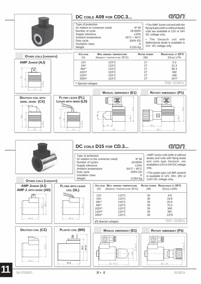
DC COILS D15 FOR CD.3...
FLYING LEADS (FL)LEADS WITH DIODO (LD)
DC COILS A09 FOR CDC.3...Type of protection(in relation to connector used) IP 65Number of cycle 18.000/hSupply tolerance ±10%Ambient temperature -30°C ÷ 60°CDuty cycle 100% EDInsulation class HWeight 0,215 Kg
VOLTAGE MAX WINDING TEMPERATURE RATED POWER RESISTANCE AT 20°C(V) (AMBIENT TEMPERATURE 25°C) (W) (OHM) ±7%
12V 123°C 27 5.324V 123°C 27 21.348V* 123°C 27 85.3102V* 123°C 27 392110V* 123°C 27 448205V* 123°C 27 1577
* Special voltages
ROTARY EMERGENCY (P1)MANUAL EMERGENCY (E1)
ETA09 - 02/2001/e
AMP JUNIOR (AJ)
DEUTSCH COIL WITH
BIDIR. DIODE (CX)
OTHER COILS (VARIANTS)
VOLTAGE MAX. WINDING TEMPERATURE RATED POWER RESISTANCE AT 20°C(V) (AMBIENT TEMPERATURE 25°C) (W) (OHM) ±10%
12V 110°C 30 4.824V 110°C 30 18.828V* 110°C 30 25.648V* 110°C 30 75.2
102V* 110°C 30 340110V* 110°C 30 387205V* 110°C 30 1375
(*) Special voltages ETD15 - 03/2001/e
DEUTSCH COIL (CZ) PLASTIC COIL (BR)
AMP JUNIOR (AJ)AMP J. WITH DIODE (AD)
56,6
57,9
68,6
5
Type of protection(in relation to the connector used) IP 66Number of cycles 18.000/hSupply tolerance ±10%Ambient temperature -54°C ÷ 60°CDuty cycle 100% EDInsulation class HWeight 0,354 Kg
• AMP Junior coils (with or withoutdiode) and coils with flying leadsand coils type Deutsch, areavailable in 12V or 24V DC voltageonly.
• The pastic type coil (BR variant)is available in 12V, 24V, 28V or110V DC voltage only.OTHER COILS (VARIANTI)
FLYING WITH LEADS
COIL (SL)
MANUAL EMERGENCY (E1) ROTARY EMERGENCY (P1)
• The AMP Junior coil and with theflying leads (with or without diode)coils are available in 12V or 24VDC voltage only.
• The Deutsch coil withbidirectional diode is available in12V DC voltage only.
File: ETLECDC3 01/2004/eXI • 9 11
OFF-HIGHWAY
MACHINERY
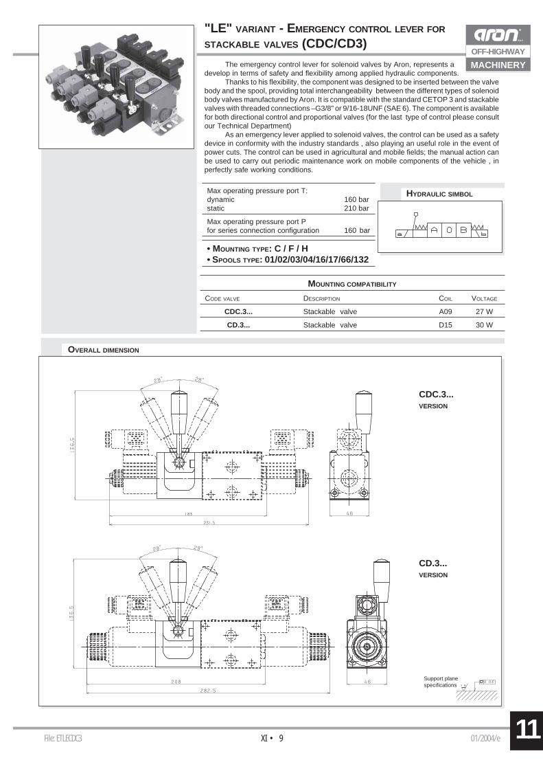
OVERALL DIMENSION
MOUNTING COMPATIBILITY
CODE VALVE DESCRIPTION COIL VOLTAGE
CDC.3... Stackable valve A09 27 W
CD.3... Stackable valve D15 30 W
HYDRAULIC SIMBOL
CDC.3...VERSION
CD.3...VERSION
The emergency control lever for solenoid valves by Aron, represents adevelop in terms of safety and flexibility among applied hydraulic components.
Thanks to his flexibility, the component was designed to be inserted between the valvebody and the spool, providing total interchangeability between the different types of solenoidbody valves manufactured by Aron. It is compatible with the standard CETOP 3 and stackablevalves with threaded connections –G3/8" or 9/16-18UNF (SAE 6). The component is availablefor both directional control and proportional valves (for the last type of control please consultour Technical Department)
As an emergency lever applied to solenoid valves, the control can be used as a safetydevice in conformity with the industry standards , also playing an useful role in the event ofpower cuts. The control can be used in agricultural and mobile fields; the manual action canbe used to carry out periodic maintenance work on mobile components of the vehicle , inperfectly safe working conditions.
Support planespecifications
"LE" VARIANT - EMERGENCY CONTROL LEVER FOR
STACKABLE VALVES (CDC/CD3)
• MOUNTING TYPE: C / F / H• SPOOLS TYPE: 01/02/03/04/16/17/66/132
Max operating pressure port T:dynamic 160 barstatic 210 bar
Max operating pressure port Pfor series connection configuration 160 bar
11 File: EFI3001 00/2002/eXI • 10
OFF-HIGHWAY
MACHINERY
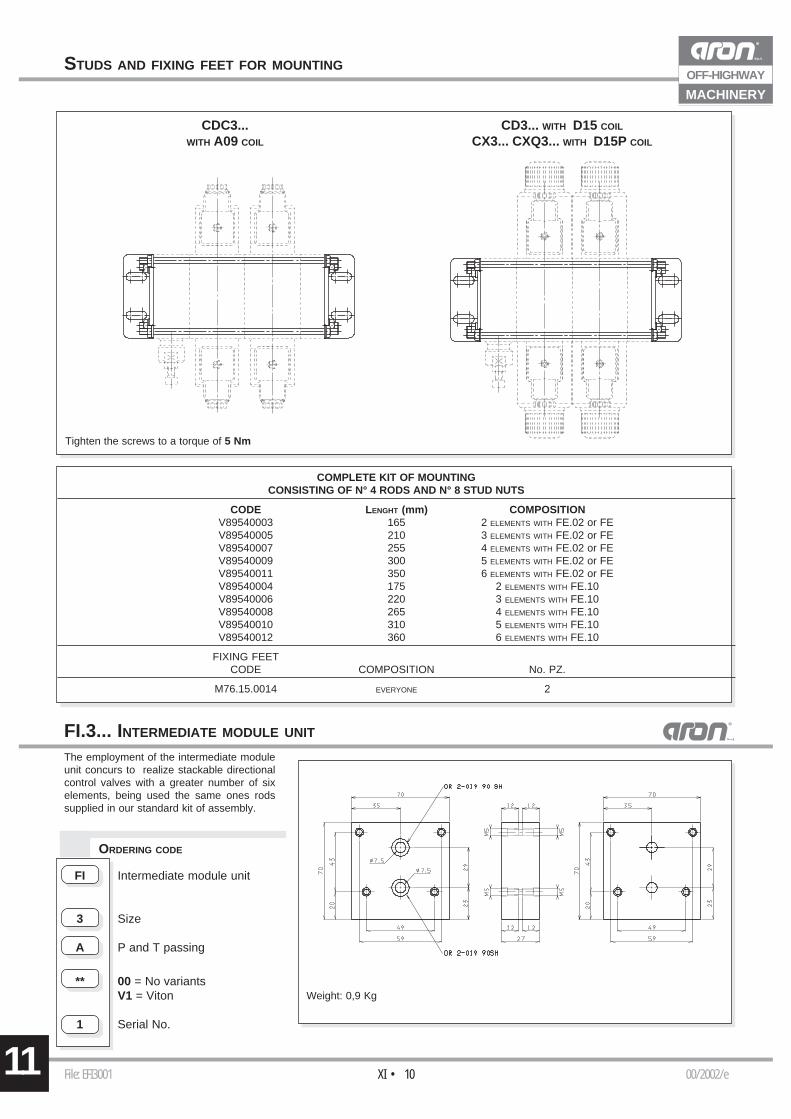
STUDS AND FIXING FEET FOR MOUNTING
COMPLETE KIT OF MOUNTINGCONSISTING OF N° 4 RODS AND N° 8 STUD NUTS
CODE LENGHT (mm) COMPOSITIONV89540003 165 2 ELEMENTS WITH FE.02 or FEV89540005 210 3 ELEMENTS WITH FE.02 or FEV89540007 255 4 ELEMENTS WITH FE.02 or FEV89540009 300 5 ELEMENTS WITH FE.02 or FEV89540011 350 6 ELEMENTS WITH FE.02 or FEV89540004 175 2 ELEMENTS WITH FE.10V89540006 220 3 ELEMENTS WITH FE.10V89540008 265 4 ELEMENTS WITH FE.10V89540010 310 5 ELEMENTS WITH FE.10V89540012 360 6 ELEMENTS WITH FE.10
FIXING FEETCODE COMPOSITION No. PZ.
M76.15.0014 EVERYONE 2
CDC3...WITH A09 COIL
CD3... WITH D15 COIL
CX3... CXQ3... WITH D15P COIL
Tighten the screws to a torque of 5 Nm
Weight: 0,9 Kg
The employment of the intermediate moduleunit concurs to realize stackable directionalcontrol valves with a greater number of sixelements, being used the same ones rodssupplied in our standard kit of assembly.
ORDERING CODE
FI.3... INTERMEDIATE MODULE UNIT
FI Intermediate module unit
3 Size
A P and T passing
** 00 = No variantsV1 = Viton
1 Serial No.
File: ECX3001 04/2002/eXI • 11 11
OFF-HIGHWAY
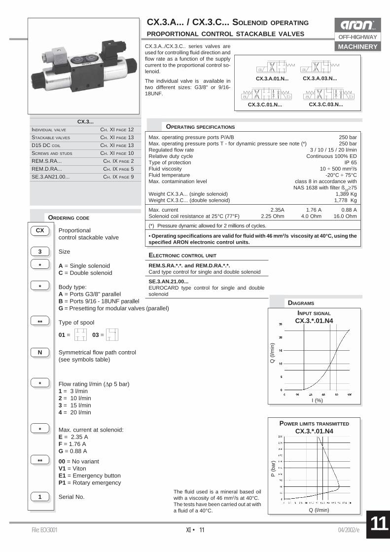
MACHINERYCX.3.A../CX.3.C.. series valves areused for controlling fluid direction andflow rate as a function of the supplycurrent to the proportional control so-lenoid.
The individual valve is available intwo different sizes: G3/8" or 9/16-18UNF.
CX.3.A... / CX.3.C... SOLENOID OPERATING
PROPORTIONAL CONTROL STACKABLE VALVES
CX.3...
INDIVIDUAL VALVE CH. XI PAGE 12
STACKABLE VALVES CH. XI PAGE 13
D15 DC COIL CH. XI PAGE 13
SCREWS AND STUDS CH. XI PAGE 10
REM.S.RA... CH. IX PAGE 2
REM.D.RA... CH. IX PAGE 5
SE.3.AN21.00... CH. IX PAGE 9
CX Proportionalcontrol stackable valve
3 Size
* A = Single solenoidC = Double solenoid
* Body type:A = Ports G3/8" parallelB = Ports 9/16 - 18UNF parallelG = Presetting for modular valves (parallel)
** Type of spool
01 = 03 =
N Symmetrical flow path control(see symbols table)
* Flow rating l/min (∆p 5 bar)1 = 3 l/min2 = 10 l/min3 = 15 l/min4 = 20 l/min
* Max. current at solenoid:E = 2.35 AF = 1.76 AG = 0.88 A
** 00 = No variantV1 = VitonE1 = Emergency buttonP1 = Rotary emergency
1 Serial No.
ORDERING CODE
I (%)
Q (
l/min
)
INPUT SIGNAL
CX.3.*.01.N4
DIAGRAMS
The fluid used is a mineral based oilwith a viscosity of 46 mm2/s at 40°C.The tests have been carried out at witha fluid of a 40°C. Q (l/min)
P (
bar)
POWER LIMITS TRANSMITTED
CX.3.*.01.N4
CX.3.A.01.N...
CX.3.C.01.N... CX.3.C.03.N...
CX.3.A.03.N...
Max. operating pressure ports P/A/B 250 barMax. operating pressure ports T - for dynamic pressure see note (*) 250 barRegulated flow rate 3 / 10 / 15 / 20 l/minRelative duty cycle Continuous 100% EDType of protection IP 65Fluid viscosity 10 ÷ 500 mm2/sFluid temperature -20°C ÷ 75°CMax. contamination level class 8 in accordance with
NAS 1638 with filter ß10≥75Weight CX.3.A... (single solenoid) 1,389 KgWeight CX.3.C... (double solenoid) 1,778 Kg
Max. current 2.35A 1.76 A 0.88 ASolenoid coil resistance at 25°C (77°F) 2.25 Ohm 4.0 Ohm 16.0 Ohm
(*) Pressure dynamic allowed for 2 millions of cycles.
ELECTRONIC CONTROL UNIT
REM.S.RA.*.*. and REM.D.RA.*.*.Card type control for single and double solenoid
SE.3.AN.21.00...EUROCARD type control for single and doublesolenoid
• Operating specifications are valid for fluid with 46 mm2/s viscosity at 40°C, using thespecified ARON electronic control units.
OPERATING SPECIFICATIONS
File: ECX3002 04/2002/eXI • 1211
OFF-HIGHWAY
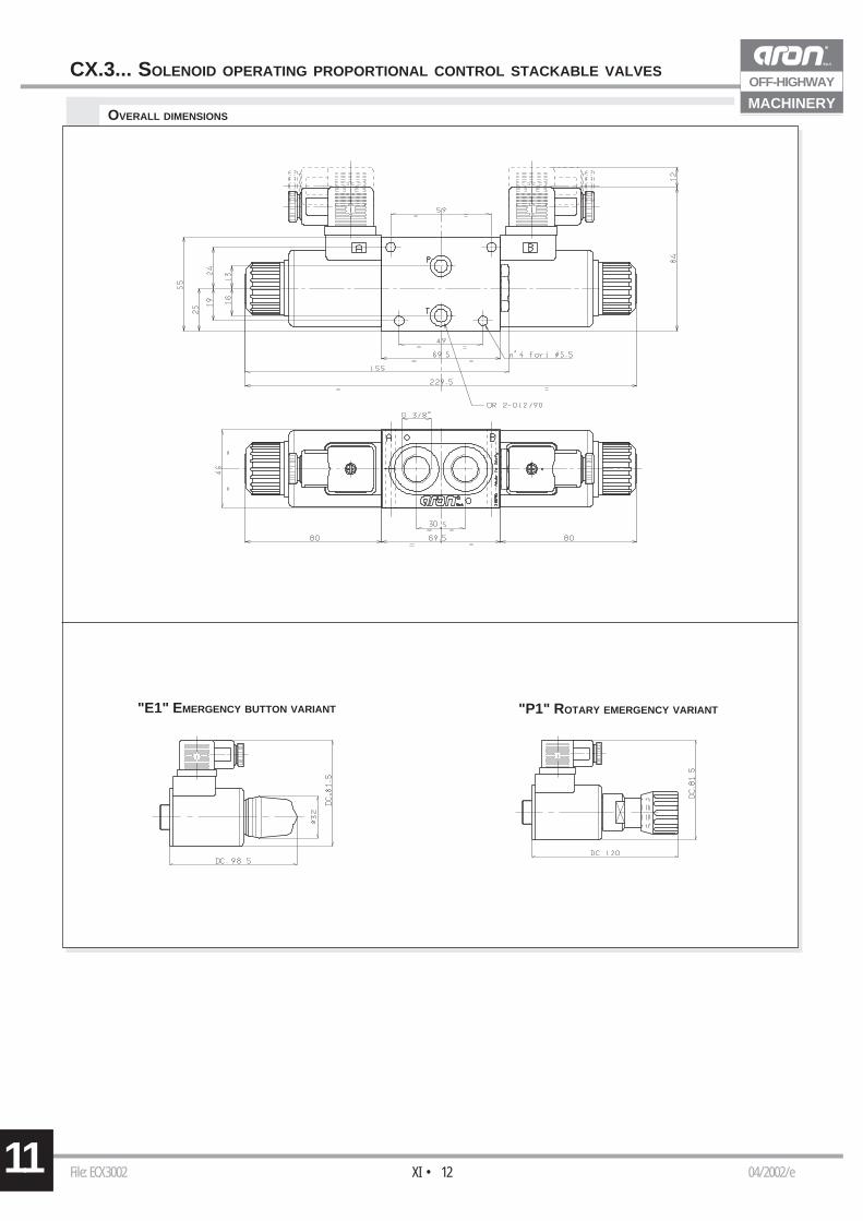
MACHINERYOVERALL DIMENSIONS
"E1" EMERGENCY BUTTON VARIANT "P1" ROTARY EMERGENCY VARIANT
CX.3... SOLENOID OPERATING PROPORTIONAL CONTROL STACKABLE VALVES
File: ECX3001 04/2002/eXI • 13 11
OFF-HIGHWAY
MACHINERY
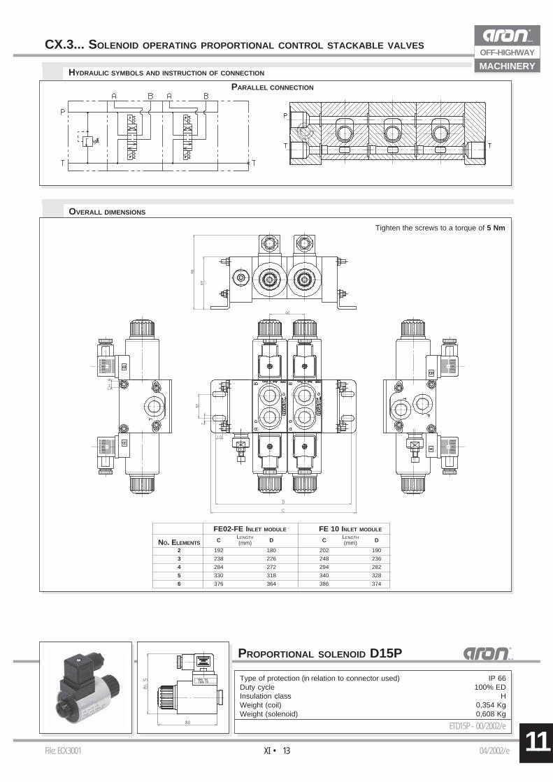
FE02-FE INLET MODULE FE 10 INLET MODULELENGTH LENGTH
NO. ELEMENTS C (mm) D C (mm) D
2 192 180 202 190
3 238 226 248 236
4 284 272 294 282
5 330 318 340 328
6 376 364 386 374
OVERALL DIMENSIONS
HYDRAULIC SYMBOLS AND INSTRUCTION OF CONNECTION
PARALLEL CONNECTION
Tighten the screws to a torque of 5 Nm
CX.3... SOLENOID OPERATING PROPORTIONAL CONTROL STACKABLE VALVES
PROPORTIONAL SOLENOID D15P
Type of protection (in relation to connector used) IP 66Duty cycle 100% EDInsulation class HWeight (coil) 0,354 KgWeight (solenoid) 0,608 Kg
ETD15P - 00/2002/e
11 File: ECXQ3001 02/2002/eXI • 14
OFF-HIGHWAY
MACHINERY
I (%)
Q (
l/min
)
P (bar)
Q (
l/min
)Q
(l/m
in)
P (bar)
CXQ.3.C.P...CXQ.3.C.T...
Q (l/min)
∆p (
bar)
Q (l/min)
∆p (
bar)
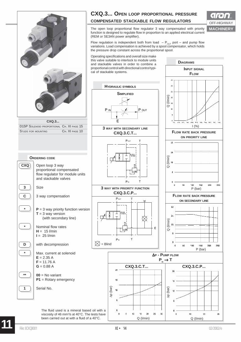
= Blind
CXQ.3...
D15P SOLENOID PROPORTIONAL CH. XI PAGE 15
STUDS FOR MOUNTING CH. XI PAGE 10
CXQ Open loop 3 wayproportional compensatedflow regulator for module unitsand stackable valves
3 Size
C 3 way compensation
* P = 3 way priority function versionT = 3 way version (with secondary line)
* Nominal flow ratesH = 15 l/minI = 25 l/min
D with decompression
* Max. current at solenoidE = 2.35 AF = 11.76 AG = 0.88 A
** 00 = No variantP1 = Rotary emergency
1 Serial No.
ORDERING CODE
The fluid used is a mineral based oil with aviscosity of 46 mm2/s at 40°C. The tests havebeen carried out at with a fluid of a 40°C.
The open loop proportional flow regulator 3 way compensated with priorityfunction is designed to regulate flow in proportion to an applied electrical current(REM or SE3AN power amplifier).
Flow regulation is independent both from load – POUT port – and pump flowvariations. Load compensation is achieved by a spool compensator, which holdsthe pressure drop constant across the proportional spool.
CXQ.3... OPEN LOOP PROPORTIONAL PRESSURE
COMPENSATED STACKABLE FLOW REGULATORS
DIAGRAMS
∆∆∆∆∆P - PUMP FLOW
PIN →→→→→ T
HYDRAULIC SYMBOLS
3 WAY WITH SECONDARY LINE
CXQ.3.C.T...
3 WAY WITH PRIORITY FUNCTION
CXQ.3.C.P...
SIMPLIFIED
INPUT SIGNAL
FLOW
FLOW RATE BACK PRESSURE
ON PRIORITY LINE
FLOW RATE BACK PRESSURE
ON SECONDARY LINE
Operating specifications and overall size makethis valve suitable to interlock to module unitsand stackable valves in order to combine aproportional control with directional control typi-cal of stackable systems.
11File: ECXQ3001 02/2002/eXI • 15
OFF-HIGHWAY
MACHINERY
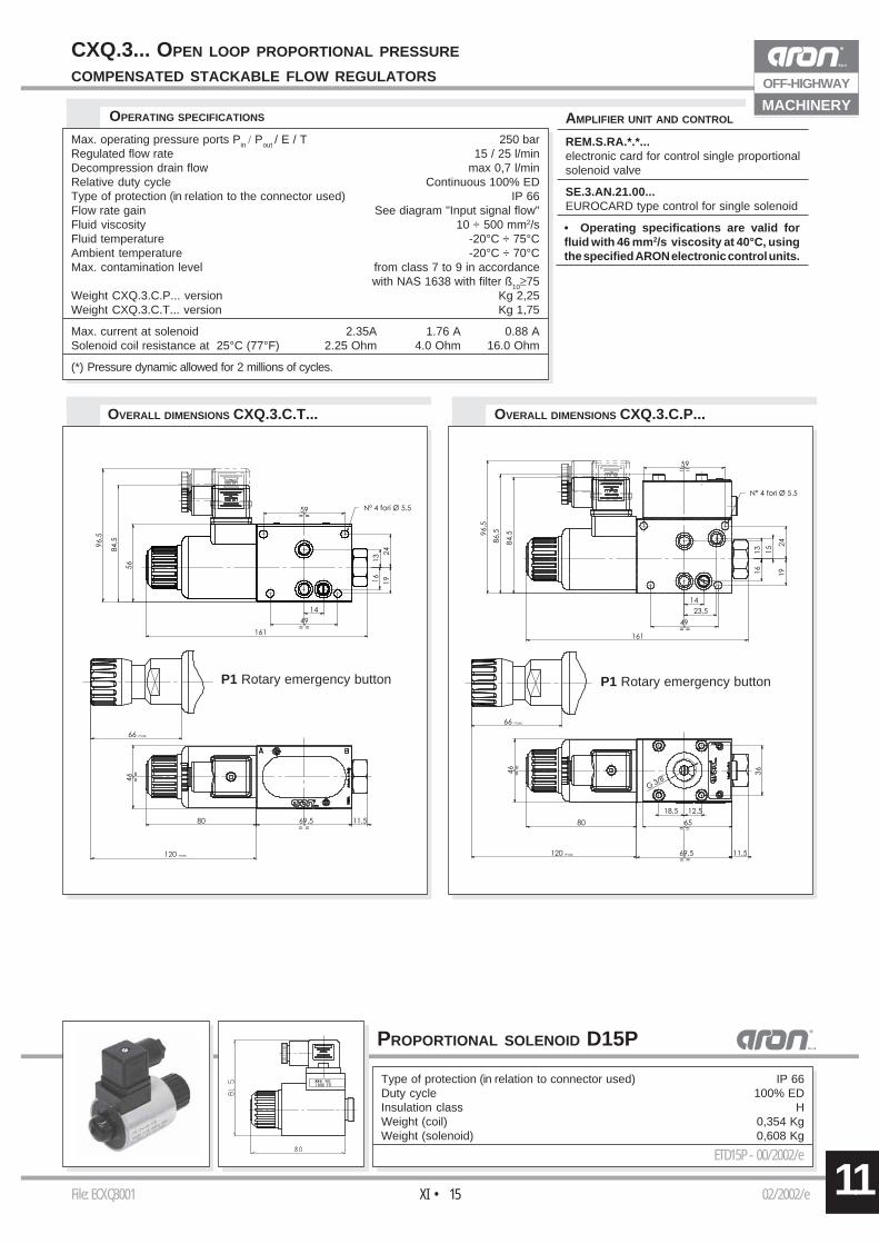
• Operating specifications are valid forfluid with 46 mm2/s viscosity at 40°C, usingthe specified ARON electronic control units.
OVERALL DIMENSIONS CXQ.3.C.P...
OPERATING SPECIFICATIONS
Max. operating pressure ports Pin / Pout / E / T 250 barRegulated flow rate 15 / 25 l/minDecompression drain flow max 0,7 l/minRelative duty cycle Continuous 100% EDType of protection (in relation to the connector used) IP 66Flow rate gain See diagram "Input signal flow"Fluid viscosity 10 ÷ 500 mm2/sFluid temperature -20°C ÷ 75°CAmbient temperature -20°C ÷ 70°CMax. contamination level from class 7 to 9 in accordance
with NAS 1638 with filter ß10≥75Weight CXQ.3.C.P... version Kg 2,25Weight CXQ.3.C.T... version Kg 1,75
Max. current at solenoid 2.35A 1.76 A 0.88 ASolenoid coil resistance at 25°C (77°F) 2.25 Ohm 4.0 Ohm 16.0 Ohm
(*) Pressure dynamic allowed for 2 millions of cycles.
CXQ.3... OPEN LOOP PROPORTIONAL PRESSURE
COMPENSATED STACKABLE FLOW REGULATORS
AMPLIFIER UNIT AND CONTROL
REM.S.RA.*.*...electronic card for control single proportionalsolenoid valve
SE.3.AN.21.00...EUROCARD type control for single solenoid
OVERALL DIMENSIONS CXQ.3.C.T...
P1 Rotary emergency button P1 Rotary emergency button
PROPORTIONAL SOLENOID D15P
Type of protection (in relation to connector used) IP 66Duty cycle 100% EDInsulation class HWeight (coil) 0,354 KgWeight (solenoid) 0,608 Kg
ETD15P - 00/2002/e
File: ECM023P001 02/2002/eXI • 1611
OFF-HIGHWAY
MACHINERY
CM02.3.P.A
CM02.3.P.B
CM02.3.P.AB
∆p (
bar)
Q (l/min)
5 bar1 bar
3
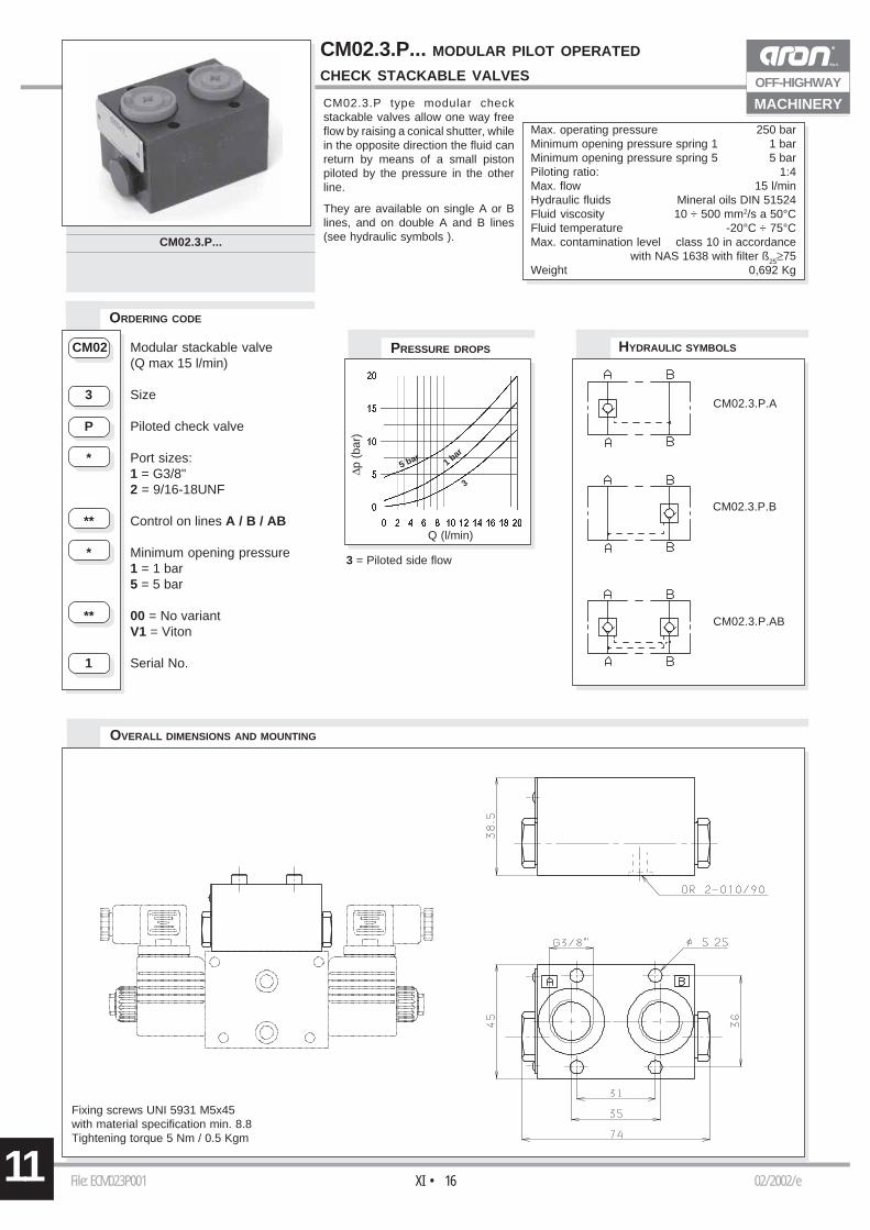
CM02.3.P... MODULAR PILOT OPERATED
CHECK STACKABLE VALVES
Max. operating pressure 250 barMinimum opening pressure spring 1 1 barMinimum opening pressure spring 5 5 barPiloting ratio: 1:4Max. flow 15 l/minHydraulic fluids Mineral oils DIN 51524Fluid viscosity 10 ÷ 500 mm2/s a 50°CFluid temperature -20°C ÷ 75°CMax. contamination level class 10 in accordance
with NAS 1638 with filter ß25≥75Weight 0,692 Kg
CM02.3.P type modular checkstackable valves allow one way freeflow by raising a conical shutter, whilein the opposite direction the fluid canreturn by means of a small pistonpiloted by the pressure in the otherline.
They are available on single A or Blines, and on double A and B lines(see hydraulic symbols ).
CM02 Modular stackable valve(Q max 15 l/min)
3 Size
P Piloted check valve
* Port sizes:1 = G3/8"2 = 9/16-18UNF
** Control on lines A / B / AB
* Minimum opening pressure1 = 1 bar5 = 5 bar
** 00 = No variantV1 = Viton
1 Serial No.
OVERALL DIMENSIONS AND MOUNTING
PRESSURE DROPS HYDRAULIC SYMBOLS
ORDERING CODE
3 = Piloted side flow
Fixing screws UNI 5931 M5x45with material specification min. 8.8Tightening torque 5 Nm / 0.5 Kgm
CM02.3.P...
File: ECM3M003 01/2002/eXI • 17 11
OFF-HIGHWAY
MACHINERY
P (
bar)
Q (l/min)
CM.3.M.A
CM.3.M.B
CM.3.M.AB
P (
bar)
Q (l/min)
3
2
1
3
21
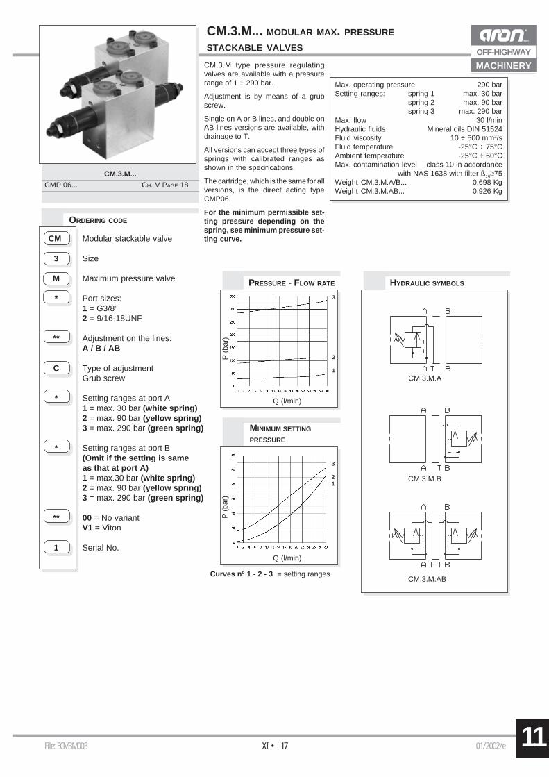
CM.3.M type pressure regulatingvalves are available with a pressurerange of 1 ÷ 290 bar.
Adjustment is by means of a grubscrew.
Single on A or B lines, and double onAB lines versions are available, withdrainage to T.
All versions can accept three types ofsprings with calibrated ranges asshown in the specifications.
The cartridge, which is the same for allversions, is the direct acting typeCMP06.
For the minimum permissible set-ting pressure depending on thespring, see minimum pressure set-ting curve.
CM.3.M... MODULAR MAX. PRESSURE
STACKABLE VALVES
CM.3.M...
CMP.06... CH. V PAGE 18
ORDERING CODE
Max. operating pressure 290 barSetting ranges: spring 1 max. 30 bar
spring 2 max. 90 barspring 3 max. 290 bar
Max. flow 30 l/minHydraulic fluids Mineral oils DIN 51524Fluid viscosity 10 ÷ 500 mm2/sFluid temperature -25°C ÷ 75°CAmbient temperature -25°C ÷ 60°CMax. contamination level class 10 in accordance
with NAS 1638 with filter ß25≥75Weight CM.3.M.A/B... 0,698 KgWeight CM.3.M.AB... 0,926 Kg
HYDRAULIC SYMBOLSPRESSURE - FLOW RATE
MINIMUM SETTING
PRESSURE
Curves n° 1 - 2 - 3 = setting ranges
CM Modular stackable valve
3 Size
M Maximum pressure valve
* Port sizes:1 = G3/8"2 = 9/16-18UNF
** Adjustment on the lines:A / B / AB
C Type of adjustmentGrub screw
* Setting ranges at port A1 = max. 30 bar (white spring)2 = max. 90 bar (yellow spring)3 = max. 290 bar (green spring)
* Setting ranges at port B(Omit if the setting is sameas that at port A)1 = max.30 bar (white spring)2 = max. 90 bar (yellow spring)3 = max. 290 bar (green spring)
** 00 = No variantV1 = Viton
1 Serial No.
File: ECM3M001 01/2002/eXI • 1811
OFF-HIGHWAY
MACHINERY
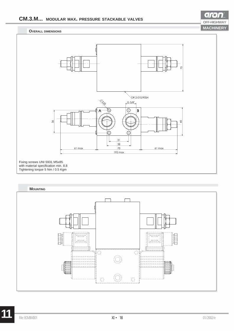
CM.3.M... MODULAR MAX. PRESSURE STACKABLE VALVES
OVERALL DIMENSIONS
MOUNTING
Fixing screws UNI 5931 M5x85with material specification min. 8.8Tightening torque 5 Nm / 0.5 Kgm
File: EFE023001 01/2001/eXI • 19 11
OFF-HIGHWAY
MACHINERY
P (
bar)
Q (l/min)
P (
bar)
Q (l/min)
4
3
2
1
4
123
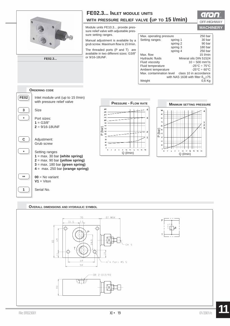
FE02.3... INLET MODULE UNITS
WITH PRESSURE RELIEF VALVE (UP TO 15 l/min)Module units FE10.3... provide pres-sure relief valve with adjustable pres-sure setting ranges.
Manual adjustment is available by agrub screw. Maximum flow is 15 l/min.
The threaded ports (P and T) areavailable in two different sizes: G3/8"or 9/16-18UNF.
ORDERING CODE
Max. operating pressure 250 barSetting ranges: spring 1 30 bar
spring 2 90 barspring 3 180 barspring 4 250 bar
Max. flow 15 l/minHydraulic fluids Mineral oils DIN 51524Fluid viscosity 10 ÷ 500 mm2/sFluid temperature -25°C ÷ 75°CAmbient temperature -25°C ÷ 60°CMax. contamination level class 10 in accordance
with NAS 1638 with filter ß25≥75Weight 0,6 Kg
FE02 Inlet module unit (up to 15 l/min)with pressure relief valve
3 Size
* Port sizes:1 = G3/8"2 = 9/16-18UNF
C Adjustment:Grub screw
* Setting ranges1 = max. 30 bar (white spring)2 = max. 90 bar (yellow spring)3 = max. 180 bar (green spring)4 = max. 250 bar (orange spring)
** 00 = No variantV1 = Viton
1 Serial No.
OVERALL DIMENSIONS AND HYDRAULIC SYMBOL
PRESSURE - FLOW RATE MINIMUM SETTING PRESSURE
FE02.3...
File: EFE103001 02/2001/eXI • 2011
OFF-HIGHWAY
MACHINERY
P (
bar)
Q (l/min)
P (
bar)
Q (l/min)
3
2
1
3
2
1
C
M
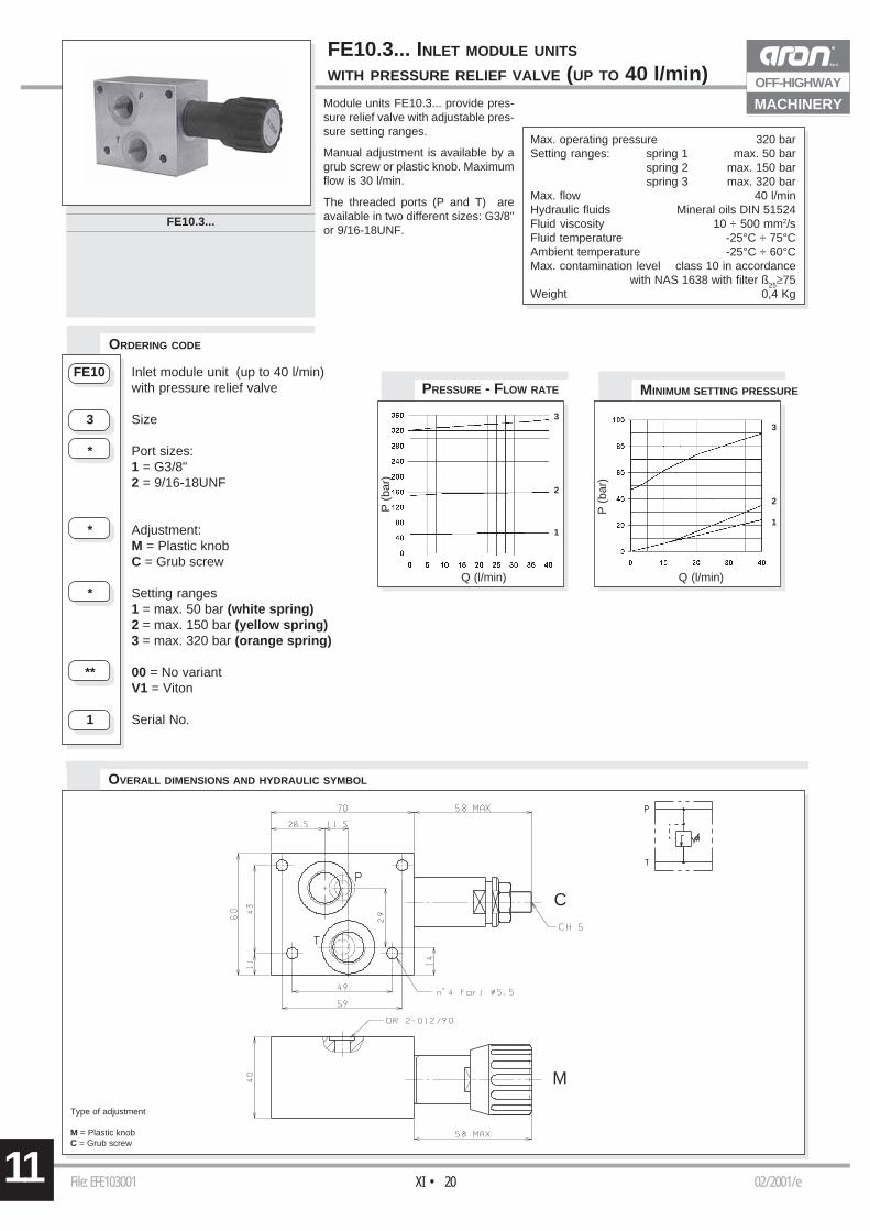
FE10.3... INLET MODULE UNITS
WITH PRESSURE RELIEF VALVE (UP TO 40 l/min)
PRESSURE - FLOW RATE
Module units FE10.3... provide pres-sure relief valve with adjustable pres-sure setting ranges.
Manual adjustment is available by agrub screw or plastic knob. Maximumflow is 30 l/min.
The threaded ports (P and T) areavailable in two different sizes: G3/8"or 9/16-18UNF.
ORDERING CODE
Max. operating pressure 320 barSetting ranges: spring 1 max. 50 bar
spring 2 max. 150 barspring 3 max. 320 bar
Max. flow 40 l/minHydraulic fluids Mineral oils DIN 51524Fluid viscosity 10 ÷ 500 mm2/sFluid temperature -25°C ÷ 75°CAmbient temperature -25°C ÷ 60°CMax. contamination level class 10 in accordance
with NAS 1638 with filter ß25≥75Weight 0,4 Kg
MINIMUM SETTING PRESSURE
OVERALL DIMENSIONS AND HYDRAULIC SYMBOL
FE10 Inlet module unit (up to 40 l/min)with pressure relief valve
3 Size
* Port sizes:1 = G3/8"2 = 9/16-18UNF
* Adjustment:M = Plastic knobC = Grub screw
* Setting ranges1 = max. 50 bar (white spring)2 = max. 150 bar (yellow spring)3 = max. 320 bar (orange spring)
** 00 = No variantV1 = Viton
1 Serial No.
FE10.3...
Type of adjustment
M = Plastic knobC = Grub screw

File: EFE10P3001 00/2004/eXI • 21 11
OFF-HIGHWAY
MACHINERY
TAB.1 - DC VOLTAGE
ORDERING CODE
Type of adjustment
M = Plastic knobC = Grub screw
Module units FE10.3... provide apressure relief valve with adjustablepressure setting ranges and anelectrical venting valve.
The pressure relief valve's manualadjustment is available by a grub screwor plastic knob. Maximum flow is30l/min.
The threaded ports (P and T) areavailable in two different sizes: G3/8"or 9/16-18UNF.
FE10.P...
Max. operating pressure 300 barMax. flow 30 l/minHydraulic fluids Mineral oils DIN 51524Fluid viscosity 10 ÷ 500 mm2/sFluid temperature -25°C ÷ 75°CAmbient temperature -25°C ÷ 60°CMax. contamination level class 10 in accordance
with NAS 1638 with filter ß25≥75Weight 1,1 Kg
Setting ranges for pressure relief valve:spring 1 max. 50 barspring 2 max. 150 barspring 3 max. 320 bar
Features for electrical venting valve:Max. excitation frequency 2 HzDuty cycle 100% EDType of protection (connector used depending) IP65
FE10 Inlet module unit (up to 30 l/min)with pressure relief valve
P Electric venting valve
3 Size
* Port sizes:1 = G3/8"2 = 9/16-18UNF
* Adjustment:M = Plastic knobC = Grub screw
* Setting ranges1 = max. 50 bar (white spring)2 = max. 150 bar (yellow spring)3 = max. 320 bar (green spring)
* Voltage for the electricventing valve (Tab. 1)
** 00 = No variantV1 = Viton
1 Serial No.
MINIMUM SETTING PRESS.
P (
bar)Q (l/min)
3
2
1
P (
bar)
Q (l/min)
3
2
1
PRESSURE - FLOW RATE
Q (l/min)
∆p (
bar)
Q (l/min)
P (
bar)
PRESSURE DROPS
LIMITS OF USE
DIAGRAMS FOR
ELECTRICAL VENTING VALVE
DIAGRAMS FOR PRESSURE RELIEF VALVE
The tests were carried out withthe solenoids at operatingtemperature, with a supplyvoltage 10% below nominalvalue and with a 40°C fluidtemperature. The fluid used isa mineral oil with a viscosity of46 mm2/s at 40°C.
C
M
L 12VM 24VN 48V*Z 102V*X 205V*W Without DC coils
* Special voltage
115Vac/50Hz120Vac/60Hzwith rectifier
115Vac/50Hz120Vac/60Hzwith rectifier
FE10.P... INLET MODULE UNITS WITH PRESSURE RELIEF
VALVE AND ELECTRICAL VENTING VALVE (UP TO 30 l/min)
11
OFF-HIGHWAY
MACHINERY
File: EF$3001 05/2001/eXI • 22
ORDERING CODE
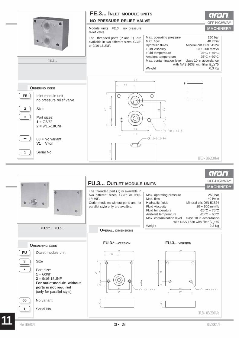
Module units FE.3... no pressurerelief valve.
The threaded ports (P and T) areavailable in two different sizes: G3/8“or 9/16-18UNF.
Max. operating pressure 250 barMax. flow 40 l/minHydraulic fluids Mineral oils DIN 51524Fluid viscosity 10 ÷ 500 mm2/sFluid temperature -25°C ÷ 75°CAmbient temperature -25°C ÷ 60°CMax. contamination level class 10 in accordance
with NAS 1638 with filter ß25≥75Weight 0,3 Kg
FE.3... INLET MODULE UNITS
NO PRESSURE RELIEF VALVE
FE Inlet module unitno pressure relief valve
3 Size
* Port sizes:1 = G3/8"2 = 9/16-18UNF
** 00 = No variantV1 = Viton
1 Serial No.
FE.3...
OVERALL DIMENSIONS
The threaded port (T) is available intwo different sizes: G3/8" or 9/16-18UNF.Outlet modules without ports and forparallel style only are availble.
OREDERING CODE
FU.3.*... FU.3...
FU Otulet module unit
3 Size
* Port size:1 = G3/8"2 = 9/16-18UNFFor outletmodule withoutports is not required(only for parallel style)
00 No variant
1 Serial No.
FU.3.*...VERSION FU.3... VERSION
IFU3 - 03/2001/e
FU.3... OUTLET MODULE UNITSOFF-HIGHWAY
MACHINERY
Max. operating pressure 250 barMax. flow 40 l/minHydraulic fluids Mineral oils DIN 51524Fluid viscosity 10 ÷ 500 mm2/sFluid temperature -25°C ÷ 75°CAmbient temperature -25°C ÷ 60°CMax. contamination level class 10 in accordance
with NAS 1638 with filter ß25≥75Weight 0,2 Kg
EFE3 - 02/2001/e