Embed Size (px)
Citation preview

CFTL: A Convertible Flash Translation Layer with Consideration of Data Access Patterns
Technical Report
Department of Computer Science
and Engineering
University of Minnesota
4-192 EECS Building
200 Union Street SE
Minneapolis, MN 55455-0159 USA
TR 09-023
CFTL: A Convertible Flash Translation Layer with Consideration of
Data Access Patterns
Dongchul Park, Biplob Debnath, and David Du
September 14, 2009


CFTL: A Convertible Flash Translation Layer withConsideration of Data Access Patterns
Dongchul Park, Biplob Debnath, and David DuUniversity of Minnesota, Twin Cities
200 Union Street SE, Minneapolis, MN 55455, [email protected], [email protected], [email protected]
ABSTRACTNAND flash memory-based storage devices are increas-ingly adopted as one of the main alternatives for magneticdisk drives. The flash translation layer (FTL) is a soft-ware/hardware interface inside NAND flash memory, whichallows existing disk-based applications to use it without anysignificant modifications. Since FTL has a critical impacton the performance of NAND flash-based devices, a vari-ety of FTL schemes have been proposed to improve theirperformance. However, existing FTLs perform well for ei-ther a read intensive workload or a write intensive work-load, not for both of them due to their fixed and static ad-dress mapping schemes. To overcome this limitation, in thispaper, we propose a novel FTL addressing scheme namedas Convertible Flash Translation Layer (CFTL, for short).CFTL is adaptive to data access patterns so that it candynamically switch the mapping of a data block to eitherread-optimized or write-optimized mapping scheme in orderto fully exploit the benefits of both schemes. By judiciouslytaking advantage of both schemes, CFTL resolves the in-trinsic problems of the existing FTLs. In addition to thisconvertible scheme, we propose an efficient caching strat-egy so as to considerably improve the CFTL performancefurther with only a simple hint. Consequently, both of theconvertible feature and caching strategy empower CFTL toachieve good read performance as well as good write per-formance. Our experimental evaluation with a variety ofrealistic workloads demonstrates that the proposed CFTLscheme outperforms other FTL schemes.
1. INTRODUCTIONNAND flash memory has come into wide use as main
data storage media in mobile devices, such as PDAs, cellphones, digital cameras, embedded sensors, and notebooksdue to its superior characteristics: smaller size, lighterweight, lower power consumption, shock resistance, lessernoise, non-volatile memory, and faster read performance [1,2, 3, 4, 5]. Recently, to boost up I/O performance and en-
Permission to make digital or hard copies of all or part of this work forpersonal or classroom use is granted without fee provided that copies arenot made or distributed for profit or commercial advantage and that copiesbear this notice and the full citation on the first page. To copy otherwise, torepublish, to post on servers or to redistribute to lists, requires prior specificpermission and/or a fee.Copyright 200X ACM X-XXXXX-XX-X/XX/XX ...$5.00.
ergy savings, flash-based Solid State Drives (SSDs) are alsobeing increasingly adopted as a storage alternative for mag-netic disk drives by laptops, desktops, and enterprise classservers [3, 4, 5, 6, 7, 8, 9]. Due to the recent advancementof the NAND flash technologies, it is expected that NANDflash-based storages will have a great impact on the designsof the future storage subsystems [4, 5, 7, 10].
A distinguishing feature of flash memory is that read oper-ations are very fast compared to magnetic disk drive. More-over, unlike disks, random read operations are as fast assequential read operations as there is no mechanical headmovement. However, a major drawback of the flash memoryis that it does not allow in-place updates (i.e., overwrite).In flash memory, data are stored in an array of blocks. Eachblock spans 32-64 pages, where a page is the smallest unitof read and write operations. Page write operations in aflash memory must be preceded by an erase operation andwithin a block pages need be to written sequentially. Thein-place update problem becomes complicated as write op-erations are performed in the page granularity, while eraseoperations are performed in the block granularity. The typ-ical access latencies for read, write, and erase operations are25 microseconds, 200 microseconds, and 1500 microseconds,respectively [7]. In addition, before the erase is done on ablock, the live (i.e., not over-written) pages in that blockneed to be moved to pre-erased blocks. Thus, an eraseoperation incurs a lot of page read and write operations,which makes it a performance critical operation. Besidesthis asymmetric read and write latency issue, flash memoryexhibits another limitation: a flash block can only be erasedfor a limited number of times (e.g., 10K-100K) [7]. Thus,frequent block erase operations reduce the lifetime of theflash memory. This is known as wear-out problem.
The flash translation layer (FTL) is a software/firmwarelayer implemented inside a flash-based storage device tomake the linear flash memory device to act like a magneticdisk drive (as shown in Figure 1). FTL emulates disk-like in-place update for a logical page number (LPN) by writing thenew page data to a different physical page number (PPN).It maintains a mapping between each LPN and its currentPPN. Finally, it marks the old PPN as invalid for the latergarbage collection. Thus, FTL enables existing applicationto use flash memory without any modification. However,internally FTL needs to deal with physical characteristicsof the flash memory. Thus, an efficient FTL scheme makesa critical effect on overall performance of flash memory asit directly affects in-place update performance and wear-outproblem.

File System
NAND Flash memory
FTL
Controller
Flash Memory System
Logical address Physical address
SRAM
Mapping Table
Figure 1: NAND Flash memory system architecture
Existing FTLs use various logical to physical page map-ping strategies to solve the in-place update and wear-outproblem. The mapping can be maintained at the pagelevel, block level, or a combination of them (hybrid). Ina page level mapping case, FTL maintains a mapping be-tween each logical page number (LPN) and physical pagenumber (PPN). Although a page level mapping scheme [11]has its merits in high block utilization and good read/writeperformance, but it requires very large memory space tostore the entire page mapping table. To overcome this largememory limitation, a block level mapping FTL tries to mapeach logical block number (LBN) to physical block number(PBN). In addition, inside a block, page offsets are alwaysfixed. An update to a page in a page level mapping maynot have to trigger a block erasure, while an update to apage in a block level mapping will trigger the erasure of theblock containing the corresponding page. Thus, the perfor-mance of a block level mapping for write intensive workloadsis much worse than that of a page level mapping. However,for the read intensive workloads, the performance of a blocklevel mapping is comparable to that of a page level mappingeven with much less memory space requirement.
To take advantage of the both page level and block levelmapping, various hybrid schemes [12, 13, 14, 15, 16, 17]have been proposed. Most of these schemes are fundamen-tally based on a block level mapping with an additionalpage level mapping restricted only to a small number oflog blocks in order to delay the block erasure. However, forwrite intensive workloads, hybrid FTL schemes still sufferfrom performance degradation due to the excessive numberof block erase operations. Recently, Gupta et al. proposeda pure page level mapping scheme called DFTL (Demand-based Flash Translation Layer) with a combination of smallSRAM and flash memory [18]. In DFTL, the entire pagelevel mapping is stored in the flash memory and tempo-ral locality is exploited in an SRAM cache to reduce lookupoverhead of the mapping table. However, DFTL incurs pagemapping lookup overhead for the workloads with fewer tem-poral locality. In addition, it suffers from frequent updatesin the pages storing the page mapping table in case of writeintensive workloads and garbage collection.
Considering the advantages and disadvantages of the ex-isting FTLs and the limited memory space, we have madethe following observations: (1) Block level mapping has agood performance for read intensive data due to its fast di-rect address translations, (2) Page level mapping manageswrite intensive data well since its high block utilization andthe reduced number of erase operations required, (3) Write
intensive pages, which define as hot pages, will be benefitedfrom the page level mapping, and (4) Read intensive pages,which we define as cold pages, will be benefited from theblock level mapping. (5) Spatial locality in a workload canhelp to improve an FTL performance. Based on these obser-vations, our goal is to design an FTL scheme that will followthe workload behavior. For a write intensive workload, itwill provide the page level mapping-like performance, whilefor a read intensive workload, it will provide the block levelmapping-like performance.
In this paper, we propose a novel FTL scheme namedas CFTL, which stands for Convertible Flash TranslationLayer. In CFTL, the core mapping table is a pure pagelevel mapping. This mapping table is stored in the flashmemory. The key idea is to force the page level mapping toprovide performance comparable to a block level mapping,if the data is turned to cold (read intensive) from hot (writeintensive) and vice versa. Since CFTL maintains core map-ping table in the page level mapping, a logical page can bemapped to any physical page. Thus, to change from blocklevel to page level mapping, no extra effort is needed. Con-trarily, to switch from page level to block level mapping, weforce CFTL to map consecutive logical pages to consecutivephysical pages.
CFTL uses a simple hot/cold block detection algorithmfor its addressing mode changes. If a logical block is identi-fied as cold, then all consecutive logical pages in the blockare stored in the consecutive physical pages of a new block.On the other hand, if logical block is identified as hot, CFTLdoes not force any restriction between the corresponding log-ical pages to physical page mapping for that block. Accord-ing to the hotness of a block, the corresponding mappingis also dynamically changed. In CFTL, since mapping ta-ble is stored in the flash memory, there can be an overheadto lookup the mapping table. To speed up the mappingtable lookup, CFTL maintains two mapping caches. Firstcache maintains the page level mappings, while second cachemaintains block level mappings. These caches exploit bothtemporal and spatial localities to reduce the lookup over-head. The main contribution of this paper is as follows:
• A Convertible FTL Scheme: Unlike other existingFTLs, CFTL is adaptive to data access patterns. Themain idea of CFTL is simple: a block level mappingdeals with read intensive data to make the best of thefast direct address translation, and a page level map-ping manages write intensive data to minimize eraseoperations thereby doing completely away with expen-sive full merge operations. Therefore, some parts offlash are addressed by a page level mapping, whilesome parts are addressed by a block level mapping.In addition, the mapping can be dynamically switchedto either scheme according to current access patternsof underlying data.
• An Efficient Caching Strategy: For the fast ad-dress translation, CFTL employs two caches to storethe mapping data. One cache is used to speed up thepage level address translation, while another cache isused to speed up the block level address translation.In particular, the page level cache is specially designedto exploit the spatial locality of data. It uses hints toimprove hit ratio. Consequently, by exploiting bothtemporal and spatial localities, these two caches make
significant contribution to improve the overall perfor-mance thereby reducing address lookup overhead.
The remainder of this paper is organized as follows. Sec-tion 2 gives an overview of flash memory and describes ex-isting FTL schemes. Section 3 explains the design and op-erations of CFTL scheme. Section 4 provides experimentalresults. Finally, Section 5 concludes the discussion.
2. BACKGROUND AND RELATED WORKIn this section, at first, we describe flash memory archi-
tecture. Next, we describe various address mapping schemesincluding page level, block level, and hybrid mappings.
2.1 Flash Memory ArchitectureThere are two types of flash memory: NOR and NAND
flash memory. NOR flash memory has a very similar inter-face to block devices, fast read speed, and access in a byteunit. So it is more appropriate to save and execute programcodes. NAND flash, on the other hand, has a distinct in-terface to block devices, relatively slower read speed, andallows access data in a page unit [19]. These features makeNAND flash more relative media to save data, not to pro-gram codes. Consequently NAND flash memory is widelyused in flash memory-based storage devices such as SSD,PDA, and other mobile devices. In this paper, we focus onthe NAND flash memory.
Figure 1 gives an overview of an NAND flash-based stor-age device. In an NAND flash memory, data are organizedas an array of blocks. Each block comprises either 32 pages(small block NAND flash) or 64 pages (large block NANDflash). In case of small block NAND flash, each page con-sists of sectors of 512 bytes and spare areas of 16 bytes.Each sector is employed to save data and each spare area isused to record LPN (Logical Page Number) or ECC (ErrorCorrecting Code). Since NAND flash does not allow over-write to the page already written, the whole block which thepage belongs to must be erased before writing operation isallowed to the page due to the feature of Erase-before-Writein flash memory. In order to balance the number of era-sures on physical blocks, an update to data in a logical pagemay migrate the updated data to a different physical page.Therefore, there must be a mapping between logical pagesto physical pages. This mapping is managed by the FlashTranslation Layer (FTL). FTL allows existing applicationsto use flash memory as a replacement for the magnetic diskwithout any code modifications. However, the performanceof the flash memory is greatly impacted by mapping schemeused in FTL.
2.2 Address Mapping SchemesTypical address mapping procedures in FTL are as fol-
lows: on receiving a logical page address from the hostsystem, FTL looks up the address mapping table and re-turns the corresponding physical address. When the hostsystem issues overwrite operations, FTL redirects the phys-ical address to an empty location in order to avoid eraseoperations. After the overwrite operation, FTL updates theaddress mapping information and the outdated block canbe erased later by a garbage collection process. FTL canmaintains the mapping table information either in the page-level, or block-level, or in a hybrid manner. In addition,FTL can store mapping table either in the SRAM or in the
0
1
2
3
4
5
9
7
12
10
11
3
Block #0
Block #1
Block #2
Block #3
LPN PPN
Page #0Page #1Page #2
Page #11
...
Write to LPN #20
1
2
3
2
0
3
1
Block #0
Block #1
Block #2
Block #3
LBN PBN
Page #0Page #1Page #2
Page #11
...
Write to LPN #11
LBN = 2 (11/4)
PBN = 2
Offset = 3 Offset = 3 (11%4)
PPN = 9
LPN: Logical Page Number
PPN: Physical Page Number
LBN: Logical Block Number
PBN: Physical Block Number
Page mapping table Block mapping table
Flash Memory Flash Memory
(a) Page level mapping (b) Block level mapping
Figure 2: Page level and block level mapping
flash memory itself. In the rest of this section, first we de-scribe SRAM based mapping schemes. Next, we describeflash memory based mapping schemes.1) SRAM-based Mapping Table: According to the gran-ularities with which the mapping information is managed,FTLs are largely classified into either a page level mapping[11] or a block level mapping [20] or hybrid.
• Page Level Mapping: This is a very flexible scheme inthat a logical page can be mapped into any physical page inflash memory (Figure 2). In addition to this feature, since itdoes not require expensive full merge operations described inthe next subsection, it shows a good overall performance forboth read and write operations. This intrinsic merit, how-ever, brings about its critical demerit–large size of memoryrequirements. That is, the size of mapping table may betoo large to be resided in SRAM of FTL. For example, letus consider a flash memory of 4GB size and a page size of2KB, this requires 2 million (221) numbers of page mappinginformation to be stored in SRAM. In this case, assumingeach mapping entry needs 8bytes, 16MB memory space isrequired only for the mapping table. This may be infeasiblefor the economic reasons.
• Block Level Mapping: In a block level address mapping,a logical page address is made up of both a logical blocknumber and its corresponding offset. Since the mapping ta-ble maintains only the mapping information between logicaland physical blocks, the size of block mapping informationis relatively smaller than that of a page level mapping. How-ever, this approach also retains an inevitable disadvantage.When the overwrite operations to logical pages are issued,the corresponding block must be migrated and remapped toa free physical block as follows: The valid pages and the up-dated page of the original data block are copied to a new freephysical block, and then the original physical block shouldbe erased. When it comes to a block level mapping, thisErase-before-Write characteristic is an unavoidable perfor-mance bottleneck in write operations.
• Hybrid Mapping: To overcome the shortcomings of thepage level and block level mapping approaches, a variety ofhybrid schemes have been proposed [12, 13, 14, 15, 16, 17].Most of these algorithms are based on a log buffer approach.In other words, there exists a page level mapping table fora limited number of blocks (log blocks) as well as a blocklevel mapping table for the data blocks. The log blocks areused to temporarily record updates to improve the writeperformance. The memory usage for mapping can also bereduced since only a small number of log blocks are allocatedfor a page level mapping. However, log blocks eventuallyneed to be erased and this will trigger a merge operation.A merge operation can be expensive and cause a number of

log block erasures.Merge operations can be classified into three types: switch
merge, partial merge, and full merge [18]. A switch mergeis triggered only when all pages in a block are sequentiallyupdated from the first logical page to the last logical page.An FTL erases the data block filled with invalid pages andswitches the log block into the data block. Since this re-quires only one block erasure, this is the cheapest mergeoperation. A partial merge is similar to the switch mergeexcept for additional valid page copies. After all the validpages are copied to the log block, an FTL simply appliesthe switch merge operation. The partial merge is executedwhen the updates do not fill one block sequentially. There-fore, this costs additional page copies as well as one blockerasure. A full merge requires the largest overhead amongmerge operations. An FTL allocates a free block and copiesthe all valid pages either from the data block or from thelog block into the free block. After copying all the validpages, the free block becomes the data block and the formerdata block and the log block are erased. Therefore, a singlefull merge operation requires as many read and write oper-ations as the number of valid pages in a block and two eraseoperations [15].
A variety of hybrid mapping schemes have been proposed[12, 13, 14, 15, 16, 17]. We summarize core features of eachscheme and discuss merits and demerits of each scheme.
BAST (Block Associative Sector Translation) [12] schemeclassifies blocks into two types, namely, data blocks for datasaving and log blocks for overwrite operations. Once anoverwrite operation is issued, an empty log block is assignedand the data is written to it instead of direct calling a blockerase operation which is very expensive. As a result of this,erase operation does not need to be performed wheneveroverwrite operation is issued. However, this scheme suffersfrom low block utilization due to log block thrashing andhot logical block problem [14].
FAST (Fully Associative Sector Translation) [14] is basedon BAST scheme but allows log blocks to be shared by alldata blocks unlike BAST in which data blocks are associ-ated to log blocks exclusively. This scheme subdivides logblocks into two types: sequential log blocks for switch op-erations and random log blocks for merge operations. Eventhough this accomplished better utilization of log blocks, itstill remains in low utilization if overwrite operations arerepeatedly requested only to the first page of each block.Moreover, random log blocks give rise to the more compli-cated merge operations due to fully associative policy.
SuperBlock FTL [15] scheme attempts to exploit the blocklevel spatial locality in workloads by allowing the page levelmapping in a superblock which is a set of consecutive blocks.This separates hot data (frequently updated data) and non-hot data into different blocks within a superblock and conse-quently the garbage collection efficiency is achieved therebyreducing the number of full merge operations. However, thisapproach uses a three-level address translation mechanismwhich leads to multiple accesses of spare area to serve therequests. In addition, it also uses a fixed size of superblockexplicitly required to be tuned according to workload re-quirements and does not efficiently make a distinction be-tween cold and hot data.
LAST (Locality-Aware Sector Translation) [16] schemeadopts multiple sequential log blocks to make use of spatiallocalities in workload in order to supplement the limitations
DLPN DPPN
8
9
10
11
570
571
501
420
MVPN=2
F V
MPPN=17
DLPN DPPN
0
1
2
3
110
111
112
113
MVPN=0
V I
MPPN=21
DLPN=10
F V
DPPN=501
DATA
Spare Area
DPPN=502
DATA
Data block Translation Block
MVPN MPPN
0
1
2
3
21
15
17
22
Global Translation Directory
DLPN DPPN
4
12
7
2
45
58
30
129
Cached Mapping Table
DLPN DPPN
0
1
2
3
110
111
129
113
MVPN=0
F V
MPPN=25
DLPN = 10(1) (6)
(2)
(3)
(4)
(5)
21 25(7)
(8)
(2, 129) (10, 501)
(9)
Figure 3: Address translation process of DFTL
of FAST. It classifies random log buffers into hot and coldpartitions to alleviate full merge cost. LAST, as the au-thors mentioned, relies on an external locality detector forits classification which cannot efficiently identify sequentialwrites when the small-sized write has a sequential locality.Moreover, the fixed size of the sequential log buffer bringsabout the overall garbage collection overhead.
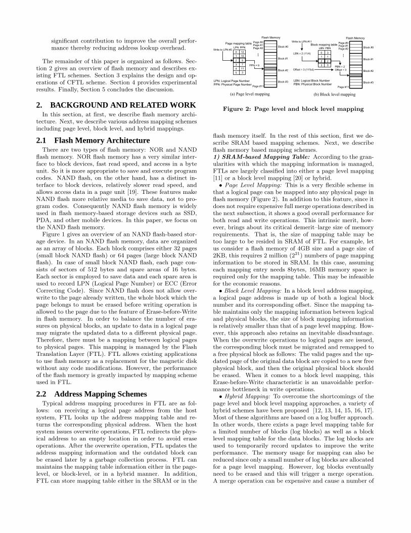
AFTL (Adaptive Two-Level Flash Translation Layer) [17]scheme maintains latest recently used mapping informationwith fine-grained address translation mechanism and theleast recently used mapping information with coarse-grainedmechanisms due to the limited source of the fine-grainedslots. Notwithstanding this two-level management, eventhough there are the large amounts of hot data, they allcannot move to fine-grained slots due to the limited size offine-grained mechanism. That is, coarse-to-fine switches in-cur corresponding fine-to-coarse switches, which causes over-head in valid data page copies. Additionally, only if all of thedata in its primary block appear in the replacement block,both corresponding coarse-grained slot and its primary blockcan be removed, which leads to low block utilization.2) Flash-based Mapping Table: Instead of storing thepage mapping table in the SRAM, it can also be stored inthe flash memory itself. Thus, the performance degradationdue to expensive full merge operations experienced by thehybrid schemes can be avoided. To that end, Gupta et al.[18] proposed a two-tier, SRAM and Flash, pure page levelmapping scheme called DFTL. Our proposed new mapping,CFTL (Convertible Flash Translation Layer), also stores themapping table in the flash memory. Since DFTL is highlyrelated to CFTL, we describe the DFTL scheme in detail.
• DFTL Architecture: DFTL maintains two types of ta-bles in SRAM, namely, Cached Mapping Table (CMT) andGlobal Translation Directory (GTD). CMT stores only asmall number of page mapping information like a cache fora fast address translation in SRAM. GTD keeps track ofall scattered page mapping tables stored in flash since out-of-updates cause translation pages get physically dispersedover the entire flash memory. That is, GTD works like tier-1mapping table in the two-tier address translation hierarchy.A complete translation pages are stored in flash due to theirrelatively big size. Translation pages retain the whole ad-dress mapping information and each page directly point tophysical data pages in flash.
• Address Translation Process in DFTL: Figure 3 il-lustrates the address translation process of DFTL. If aread/write request hits the CMT in SRAM, it is served di-rectly by using the mapping information stored in CMT.
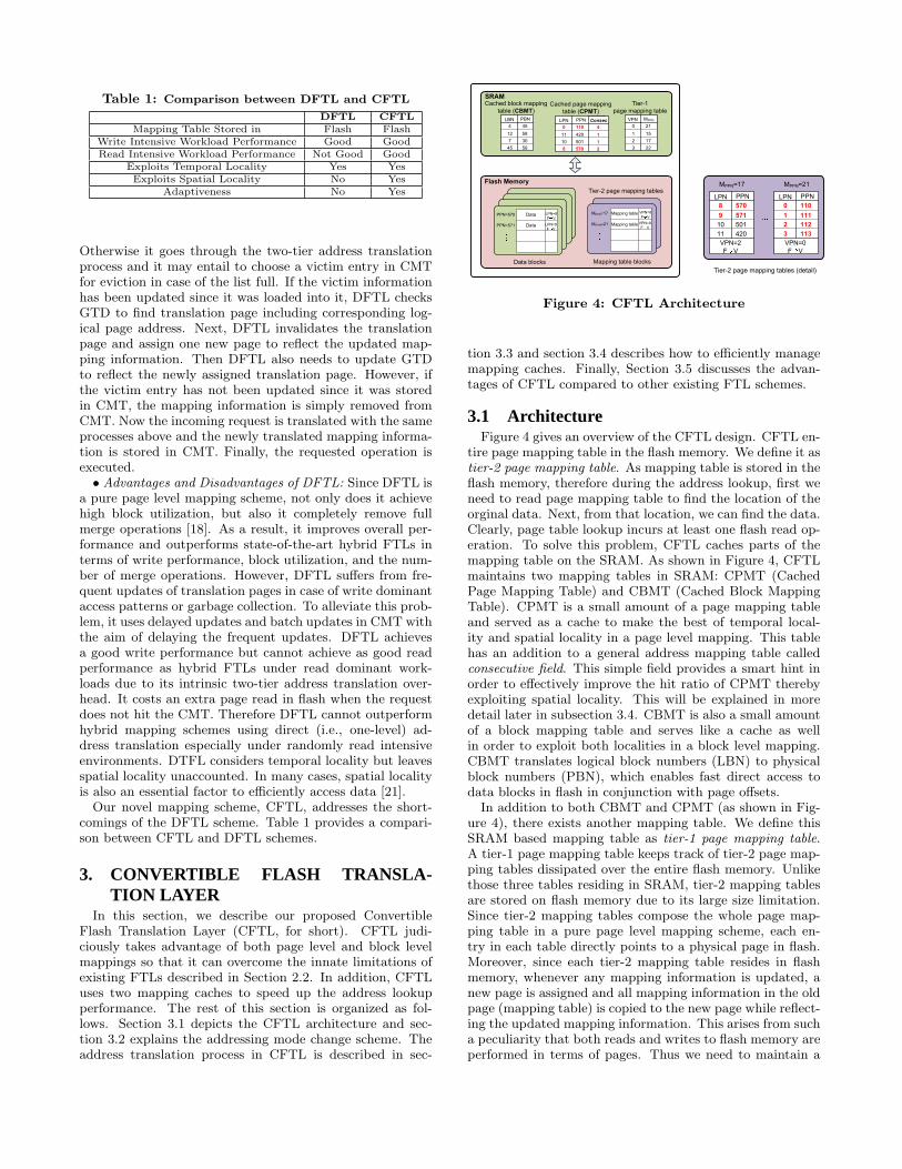
Table 1: Comparison between DFTL and CFTL
DFTL CFTLMapping Table Stored in Flash Flash
Write Intensive Workload Performance Good GoodRead Intensive Workload Performance Not Good Good
Exploits Temporal Locality Yes YesExploits Spatial Locality No Yes
Adaptiveness No Yes
Otherwise it goes through the two-tier address translationprocess and it may entail to choose a victim entry in CMTfor eviction in case of the list full. If the victim informationhas been updated since it was loaded into it, DFTL checksGTD to find translation page including corresponding log-ical page address. Next, DFTL invalidates the translationpage and assign one new page to reflect the updated map-ping information. Then DFTL also needs to update GTDto reflect the newly assigned translation page. However, ifthe victim entry has not been updated since it was storedin CMT, the mapping information is simply removed fromCMT. Now the incoming request is translated with the sameprocesses above and the newly translated mapping informa-tion is stored in CMT. Finally, the requested operation isexecuted.• Advantages and Disadvantages of DFTL: Since DFTL is
a pure page level mapping scheme, not only does it achievehigh block utilization, but also it completely remove fullmerge operations [18]. As a result, it improves overall per-formance and outperforms state-of-the-art hybrid FTLs interms of write performance, block utilization, and the num-ber of merge operations. However, DFTL suffers from fre-quent updates of translation pages in case of write dominantaccess patterns or garbage collection. To alleviate this prob-lem, it uses delayed updates and batch updates in CMT withthe aim of delaying the frequent updates. DFTL achievesa good write performance but cannot achieve as good readperformance as hybrid FTLs under read dominant work-loads due to its intrinsic two-tier address translation over-head. It costs an extra page read in flash when the requestdoes not hit the CMT. Therefore DFTL cannot outperformhybrid mapping schemes using direct (i.e., one-level) ad-dress translation especially under randomly read intensiveenvironments. DTFL considers temporal locality but leavesspatial locality unaccounted. In many cases, spatial localityis also an essential factor to efficiently access data [21].
Our novel mapping scheme, CFTL, addresses the short-comings of the DFTL scheme. Table 1 provides a compari-son between CFTL and DFTL schemes.
3. CONVERTIBLE FLASH TRANSLA-TION LAYER
In this section, we describe our proposed ConvertibleFlash Translation Layer (CFTL, for short). CFTL judi-ciously takes advantage of both page level and block levelmappings so that it can overcome the innate limitations ofexisting FTLs described in Section 2.2. In addition, CFTLuses two mapping caches to speed up the address lookupperformance. The rest of this section is organized as fol-lows. Section 3.1 depicts the CFTL architecture and sec-tion 3.2 explains the addressing mode change scheme. Theaddress translation process in CFTL is described in sec-
Cached page mapping
table (CPMT)
Data blocks Mapping table blocks
SRAM
Flash Memory
LPN PPN
0
11
10
8
110
420
501
570
Consec
4
1
1
2
VPN MPPN
0
1
2
3
21
15
17
22
Tier-1
page mapping table
LBN PBN
4
12
7
45
45
58
30
56
Cached block mapping
table (CBMT)
MPPN=17 VPN=8
F V
MPPN=21 VPN=9
F V
Mapping table
Mapping table
Tier-2 page mapping tablesLPN PPN
8
9
10
11
570
571
501
420
VPN=2
F V
MPPN=17
LPN PPN
0
1
2
3
110
111
112
113
VPN=0
F V
MPPN=21
Tier-2 page mapping tables (detail)
PPN=570 LPN=8
F V
PPN=571 LPN=9
F V
Data
Data
Figure 4: CFTL Architecture
tion 3.3 and section 3.4 describes how to efficiently managemapping caches. Finally, Section 3.5 discusses the advan-tages of CFTL compared to other existing FTL schemes.
3.1 ArchitectureFigure 4 gives an overview of the CFTL design. CFTL en-
tire page mapping table in the flash memory. We define it astier-2 page mapping table. As mapping table is stored in theflash memory, therefore during the address lookup, first weneed to read page mapping table to find the location of theorginal data. Next, from that location, we can find the data.Clearly, page table lookup incurs at least one flash read op-eration. To solve this problem, CFTL caches parts of themapping table on the SRAM. As shown in Figure 4, CFTLmaintains two mapping tables in SRAM: CPMT (CachedPage Mapping Table) and CBMT (Cached Block MappingTable). CPMT is a small amount of a page mapping tableand served as a cache to make the best of temporal local-ity and spatial locality in a page level mapping. This tablehas an addition to a general address mapping table calledconsecutive field. This simple field provides a smart hint inorder to effectively improve the hit ratio of CPMT therebyexploiting spatial locality. This will be explained in moredetail later in subsection 3.4. CBMT is also a small amountof a block mapping table and serves like a cache as wellin order to exploit both localities in a block level mapping.CBMT translates logical block numbers (LBN) to physicalblock numbers (PBN), which enables fast direct access todata blocks in flash in conjunction with page offsets.
In addition to both CBMT and CPMT (as shown in Fig-ure 4), there exists another mapping table. We define thisSRAM based mapping table as tier-1 page mapping table.A tier-1 page mapping table keeps track of tier-2 page map-ping tables dissipated over the entire flash memory. Unlikethose three tables residing in SRAM, tier-2 mapping tablesare stored on flash memory due to its large size limitation.Since tier-2 mapping tables compose the whole page map-ping table in a pure page level mapping scheme, each en-try in each table directly points to a physical page in flash.Moreover, since each tier-2 mapping table resides in flashmemory, whenever any mapping information is updated, anew page is assigned and all mapping information in the oldpage (mapping table) is copied to the new page while reflect-ing the updated mapping information. This arises from sucha peculiarity that both reads and writes to flash memory areperformed in terms of pages. Thus we need to maintain a
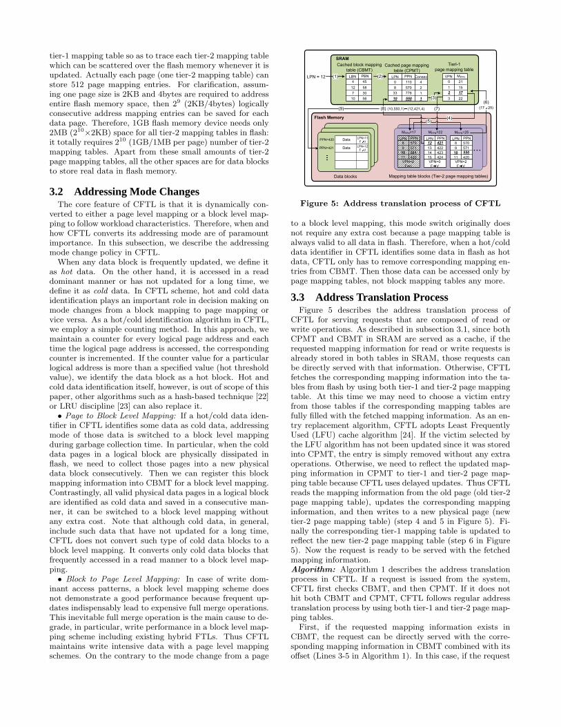
tier-1 mapping table so as to trace each tier-2 mapping tablewhich can be scattered over the flash memory whenever it isupdated. Actually each page (one tier-2 mapping table) canstore 512 page mapping entries. For clarification, assum-ing one page size is 2KB and 4bytes are required to addressentire flash memory space, then 29 (2KB/4bytes) logicallyconsecutive address mapping entries can be saved for eachdata page. Therefore, 1GB flash memory device needs only2MB (210
×2KB) space for all tier-2 mapping tables in flash:it totally requires 210 (1GB/1MB per page) number of tier-2mapping tables. Apart from these small amounts of tier-2page mapping tables, all the other spaces are for data blocksto store real data in flash memory.
3.2 Addressing Mode ChangesThe core feature of CFTL is that it is dynamically con-
verted to either a page level mapping or a block level map-ping to follow workload characteristics. Therefore, when andhow CFTL converts its addressing mode are of paramountimportance. In this subsection, we describe the addressingmode change policy in CFTL.
When any data block is frequently updated, we define itas hot data. On the other hand, it is accessed in a readdominant manner or has not updated for a long time, wedefine it as cold data. In CFTL scheme, hot and cold dataidentification plays an important role in decision making onmode changes from a block mapping to page mapping orvice versa. As a hot/cold identification algorithm in CFTL,we employ a simple counting method. In this approach, wemaintain a counter for every logical page address and eachtime the logical page address is accessed, the correspondingcounter is incremented. If the counter value for a particularlogical address is more than a specified value (hot thresholdvalue), we identify the data block as a hot block. Hot andcold data identification itself, however, is out of scope of thispaper, other algorithms such as a hash-based technique [22]or LRU discipline [23] can also replace it.• Page to Block Level Mapping: If a hot/cold data iden-
tifier in CFTL identifies some data as cold data, addressingmode of those data is switched to a block level mappingduring garbage collection time. In particular, when the colddata pages in a logical block are physically dissipated inflash, we need to collect those pages into a new physicaldata block consecutively. Then we can register this blockmapping information into CBMT for a block level mapping.Contrastingly, all valid physical data pages in a logical blockare identified as cold data and saved in a consecutive man-ner, it can be switched to a block level mapping withoutany extra cost. Note that although cold data, in general,include such data that have not updated for a long time,CFTL does not convert such type of cold data blocks to ablock level mapping. It converts only cold data blocks thatfrequently accessed in a read manner to a block level map-ping.• Block to Page Level Mapping: In case of write dom-
inant access patterns, a block level mapping scheme doesnot demonstrate a good performance because frequent up-dates indispensably lead to expensive full merge operations.This inevitable full merge operation is the main cause to de-grade, in particular, write performance in a block level map-ping scheme including existing hybrid FTLs. Thus CFTLmaintains write intensive data with a page level mappingschemes. On the contrary to the mode change from a page
Cached page mapping
table (CPMT)
Data blocks Mapping table blocks (Tier-2 page mapping tables)
SRAM
Flash Memory
LPN PPN
0
33
10
8
110
778
550
570
Consec
4
1
1
2
VPN MPPN
0
1
2
3
21
15
17
22
Tierl-1
page mapping table
LBN PBN
4
12
7
10
45
58
30
56
Cached block mapping
table (CBMT)
PPN=420LPN=11
F V
PPN=421LPN=12
F V
Data
Data
LPN PPN
8
9
10
11
570
571
501
420
VPN=2
F I
MPPN=17
LPN PPN
12
13
14
15
421
422
423
424
VPN=0
F V
MPPN=22
…
LPN PPN
8
9
10
11
570
571
550
420
VPN=2
F V
MPPN=25
LPN = 12 (1) (2)
(3)
(4)(5)
(6)
(17 25)(7)(8) (10,550,1) (12,421,4)(9)
Figure 5: Address translation process of CFTL
to a block level mapping, this mode switch originally doesnot require any extra cost because a page mapping table isalways valid to all data in flash. Therefore, when a hot/colddata identifier in CFTL identifies some data in flash as hotdata, CFTL only has to remove corresponding mapping en-tries from CBMT. Then those data can be accessed only bypage mapping tables, not block mapping tables any more.
3.3 Address Translation ProcessFigure 5 describes the address translation process of
CFTL for serving requests that are composed of read orwrite operations. As described in subsection 3.1, since bothCPMT and CBMT in SRAM are served as a cache, if therequested mapping information for read or write requests isalready stored in both tables in SRAM, those requests canbe directly served with that information. Otherwise, CFTLfetches the corresponding mapping information into the ta-bles from flash by using both tier-1 and tier-2 page mappingtable. At this time we may need to choose a victim entryfrom those tables if the corresponding mapping tables arefully filled with the fetched mapping information. As an en-try replacement algorithm, CFTL adopts Least FrequentlyUsed (LFU) cache algorithm [24]. If the victim selected bythe LFU algorithm has not been updated since it was storedinto CPMT, the entry is simply removed without any extraoperations. Otherwise, we need to reflect the updated map-ping information in CPMT to tier-1 and tier-2 page map-ping table because CFTL uses delayed updates. Thus CFTLreads the mapping information from the old page (old tier-2page mapping table), updates the corresponding mappinginformation, and then writes to a new physical page (newtier-2 page mapping table) (step 4 and 5 in Figure 5). Fi-nally the corresponding tier-1 mapping table is updated toreflect the new tier-2 page mapping table (step 6 in Figure5). Now the request is ready to be served with the fetchedmapping information.Algorithm: Algorithm 1 describes the address translationprocess in CFTL. If a request is issued from the system,CFTL first checks CBMT, and then CPMT. If it does nothit both CBMT and CPMT, CFTL follows regular addresstranslation process by using both tier-1 and tier-2 page map-ping tables.
First, if the requested mapping information exists inCBMT, the request can be directly served with the corre-sponding mapping information in CBMT combined with itsoffset (Lines 3-5 in Algorithm 1). In this case, if the request
entails write operation in flash, we update the correspond-ing mapping information in CPMT (Line 8 in Algorithm 1).Since the block mapping scheme in CFTL does not main-tain log blocks, if any update request is issued to the pagesmanaged by CBMT, the corresponding update informationis stored in CPMT. This update process follows the CPMTaddress translation process. This will be described in moredetail next.
Second, if the request does not hit CBMT, CFTL checksCPMT next. If the mapping information is present inCPMT, the request is also served directly with the infor-mation. In addition, if the request is related to a writeoperation, the corresponding entry in CPMT needs to beupdated with the new PPN (Lines 13-20 in Algorithm 1).
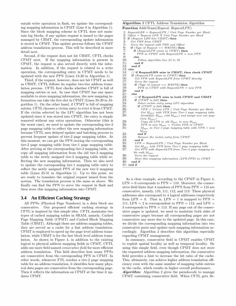
Third, if the request, however, does not hit CPMT as wellas CBMT, CFTL follows its regular two-tier address trans-lation process. CFTL first checks whether CPMT is full ofmapping entries or not. In case that CPMT has any spaceavailable to store mapping information, the new mapping in-formation can take the free slot in CPMT (Lines 35-39 in Al-gorithm 1). On the other hand, if CPMT is full of mappingentries, CFTL chooses a victim entry to evict it from CPMT.If the victim selected by the LFU algorithm has not beenupdated since it was stored into CPMT, the entry is simplyremoved without any extra operations. Otherwise (this isthe worst case), we need to update the corresponding tier-2page mapping table to reflect the new mapping informationbecause CFTL uses delayed update and batching process toprevent frequent update of tier-2 page mapping tables. Atthis moment, we can get the PPN storing the correspondingtier-2 page mapping table from tier-1 page mapping table.After arriving at the corresponding tier-2 mapping table, wecopy all mapping information from the old tier-2 mappingtable to the newly assigned tier-2 mapping table while re-flecting the new mapping information. Then we also needto update the corresponding tier-1 mapping table entry toreflect the newly assigned PPN of the new tier-2 mappingtable (Lines 25-31 in Algorithm 1). Up to this point, weare ready to translate the original request issued from thesystem. The translation process is the same as above. Wefinally can find the PPN to serve the request in flash andthen store this mapping information into CPMT.
3.4 An Efficient Caching StrategyAll PPNs (Physical Page Numbers) in a data block are
consecutive. Our proposed efficient caching strategy inCFTL is inspired by this simple idea. CFTL maintains twotypes of cached mapping tables in SRAM, namely, CachedPage Mapping Table (CPMT) and Cached Block MappingTable (CBMT). Although these are address mapping tables,they are served as a cache for a fast address translation.CPMT is employed to speed up the page level address trans-lation, while CBMT is for the fast block level address trans-lation. As shown in Figure 4, in addition to the existinglogical to physical address mapping fields in CPMT, CFTLadds one more field named consecutive field for more efficientaddress translation. This field describes how many PPNsare consecutive from the corresponding PPN in CPMT. Inother words, whenever FTL reaches a tier-2 page mappingtable for an address translation, it identifies how many phys-ical data pages are consecutive from the corresponding page.Then it reflects the information on CPMT at the time it up-dates CPMT.
Algorithm 1 CFTL Address Translation Algorithm
Function AddrTrans(Request, RequestLPN )1: RequestLBN = RequestLPN / Unit Page Number per Block2: Offset = Request LPN % Unit Page Number per Block3: if (Request LBN hits CBMT) then4: Get PBN from CBMT5: Serve the request with PBN and Offset6: if (Type of Request == WRITE) then7: if (RequestLPN exists in CPMT) then8: PPN in CPMT with RequestLPN = new PPN9: else10: Follow algorithm line 23 to 3911: end if12: end if13: else14: // if RequestLBN miss in CBMT, then check CPMT15: if (RequestLPN exists in CPMT) then16: Get PPN with RequestLPN from CPMT directly17: Serve the request18: if (Type of request == WRITE) then19: PPN in CPMT with RequestLPN = new PPN20: end if21: else22: // if RequestLPN miss in both CPMT and CBMT23: if (CPMT is full) then24: Select victim entry using LFU algorithm25: if (CPMT is full) then26: VPN = Victim LPN / Unit Page Number per Block27: Get Mppn with VPN from Tier-1 page mapping table28: Invalidate Mppn (old Mppn) and assign new one page
(new Mppn)29: Copy all LPN in old Mppn to new Mppn
30: PPN in new Mppn = Victim PPN in CPMT31: Mppn in Tier-1 page mapping table with VPN = new
Mppn
32: end if33: Remove the victim entry from CPMT34: end if35: VPN = RequestLPN / Unit Page Number per Block36: Get Mppn with VPN from Tier-1 page mapping table37: Get PPN with RequestLPN from Tier-2 page mapping ta-
ble with Mppn
38: Serve the request39: Store this mapping information (LPN,PPN) to CPMT40: end if41: end if
As a clear example, according to the CPMT in Figure 4,LPN = 0 corresponds to PPN = 110. Moreover, the consec-utive field hints that 4 numbers of PPN from PPN = 110 areconsecutive, namely, 110, 111, 112, and 113. These physicaladdresses also correspond to 4 logical addresses respectivelyfrom LPN = 0. That is, LPN = 1 is mapped to PPN =111, LPN = 2 is correspondent to PPN = 112, and LPN =3 corresponds to PPN = 113. If any page out of the consec-utive pages is updated, we need to maintain both sides ofconsecutive pages because all corresponding pages are notconsecutive any more due to the updated page. In this case,we divide the corresponding mapping information into twoconsecutive parts and update each mapping information ac-cordingly. Algorithm 2 describes this algorithm especiallyregarding CPMT management.
In summary, consecutive field in CPMT enables CPMTto exploit spatial locality as well as temporal locality. Byusing this simple field, even though CPMT does not storethe requested address mapping information, the consecutivefield provides a hint to increase the hit ratio of the cache.This, ultimately, can achieve higher address translation effi-ciency even with the same number of mapping table entriesin the cache, which results in higher overall performance.Algorithm: Algorithm 2 gives the pseudocode to manageCPMT containing consecutive field. When CFTL gets Re-
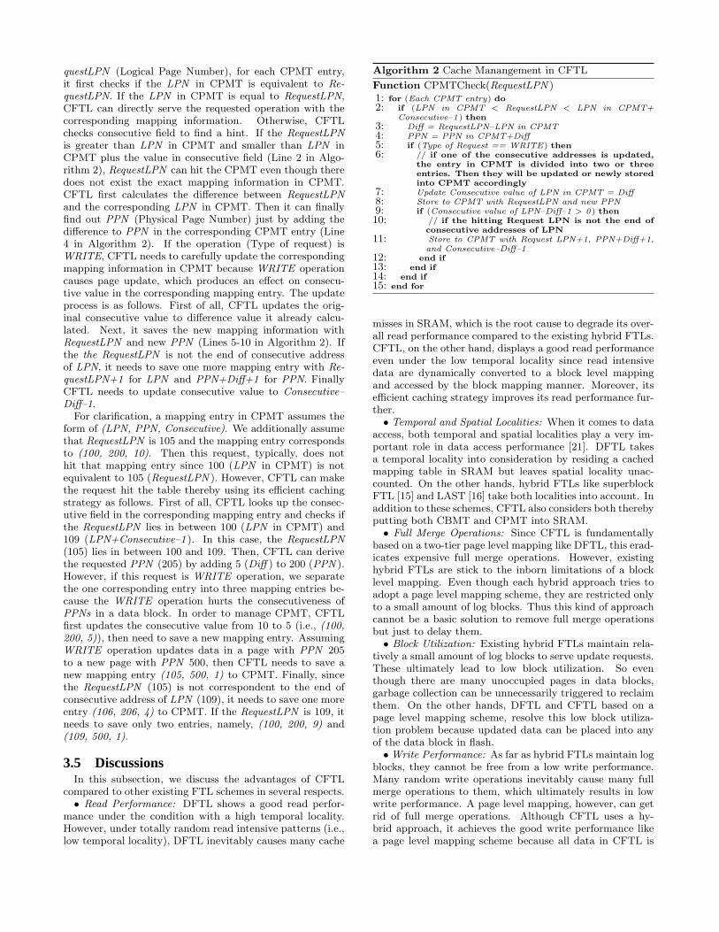
questLPN (Logical Page Number), for each CPMT entry,it first checks if the LPN in CPMT is equivalent to Re-questLPN. If the LPN in CPMT is equal to RequestLPN,CFTL can directly serve the requested operation with thecorresponding mapping information. Otherwise, CFTLchecks consecutive field to find a hint. If the RequestLPNis greater than LPN in CPMT and smaller than LPN inCPMT plus the value in consecutive field (Line 2 in Algo-rithm 2), RequestLPN can hit the CPMT even though theredoes not exist the exact mapping information in CPMT.CFTL first calculates the difference between RequestLPNand the corresponding LPN in CPMT. Then it can finallyfind out PPN (Physical Page Number) just by adding thedifference to PPN in the corresponding CPMT entry (Line4 in Algorithm 2). If the operation (Type of request) isWRITE, CFTL needs to carefully update the correspondingmapping information in CPMT because WRITE operationcauses page update, which produces an effect on consecu-tive value in the corresponding mapping entry. The updateprocess is as follows. First of all, CFTL updates the orig-inal consecutive value to difference value it already calcu-lated. Next, it saves the new mapping information withRequestLPN and new PPN (Lines 5-10 in Algorithm 2). Ifthe the RequestLPN is not the end of consecutive addressof LPN, it needs to save one more mapping entry with Re-questLPN+1 for LPN and PPN+Diff+1 for PPN. FinallyCFTL needs to update consecutive value to Consecutive–Diff–1.
For clarification, a mapping entry in CPMT assumes theform of (LPN, PPN, Consecutive). We additionally assumethat RequestLPN is 105 and the mapping entry correspondsto (100, 200, 10). Then this request, typically, does nothit that mapping entry since 100 (LPN in CPMT) is notequivalent to 105 (RequestLPN ). However, CFTL can makethe request hit the table thereby using its efficient cachingstrategy as follows. First of all, CFTL looks up the consec-utive field in the corresponding mapping entry and checks ifthe RequestLPN lies in between 100 (LPN in CPMT) and109 (LPN+Consecutive–1 ). In this case, the RequestLPN(105) lies in between 100 and 109. Then, CFTL can derivethe requested PPN (205) by adding 5 (Diff ) to 200 (PPN ).However, if this request is WRITE operation, we separatethe one corresponding entry into three mapping entries be-cause the WRITE operation hurts the consecutiveness ofPPNs in a data block. In order to manage CPMT, CFTLfirst updates the consecutive value from 10 to 5 (i.e., (100,200, 5)), then need to save a new mapping entry. AssumingWRITE operation updates data in a page with PPN 205to a new page with PPN 500, then CFTL needs to save anew mapping entry (105, 500, 1) to CPMT. Finally, sincethe RequestLPN (105) is not correspondent to the end ofconsecutive address of LPN (109), it needs to save one moreentry (106, 206, 4) to CPMT. If the RequestLPN is 109, itneeds to save only two entries, namely, (100, 200, 9) and(109, 500, 1).
3.5 DiscussionsIn this subsection, we discuss the advantages of CFTL
compared to other existing FTL schemes in several respects.• Read Performance: DFTL shows a good read perfor-
mance under the condition with a high temporal locality.However, under totally random read intensive patterns (i.e.,low temporal locality), DFTL inevitably causes many cache
Algorithm 2 Cache Manangement in CFTL
Function CPMTCheck(RequestLPN )1: for (Each CPMT entry) do2: if (LPN in CPMT < RequestLPN < LPN in CPMT+
Consecutive–1) then3: Diff = RequestLPN–LPN in CPMT4: PPN = PPN in CPMT+Diff5: if (Type of Request == WRITE) then6: // if one of the consecutive addresses is updated,
the entry in CPMT is divided into two or threeentries. Then they will be updated or newly storedinto CPMT accordingly
7: Update Consecutive value of LPN in CPMT = Diff8: Store to CPMT with RequestLPN and new PPN9: if (Consecutive value of LPN–Diff–1 > 0) then10: // if the hitting Request LPN is not the end of
consecutive addresses of LPN11: Store to CPMT with Request LPN+1, PPN+Diff+1,
and Consecutive–Diff–112: end if13: end if14: end if15: end for
misses in SRAM, which is the root cause to degrade its over-all read performance compared to the existing hybrid FTLs.CFTL, on the other hand, displays a good read performanceeven under the low temporal locality since read intensivedata are dynamically converted to a block level mappingand accessed by the block mapping manner. Moreover, itsefficient caching strategy improves its read performance fur-ther.
• Temporal and Spatial Localities: When it comes to dataaccess, both temporal and spatial localities play a very im-portant role in data access performance [21]. DFTL takesa temporal locality into consideration by residing a cachedmapping table in SRAM but leaves spatial locality unac-counted. On the other hands, hybrid FTLs like superblockFTL [15] and LAST [16] take both localities into account. Inaddition to these schemes, CFTL also considers both therebyputting both CBMT and CPMT into SRAM.
• Full Merge Operations: Since CFTL is fundamentallybased on a two-tier page level mapping like DFTL, this erad-icates expensive full merge operations. However, existinghybrid FTLs are stick to the inborn limitations of a blocklevel mapping. Even though each hybrid approach tries toadopt a page level mapping scheme, they are restricted onlyto a small amount of log blocks. Thus this kind of approachcannot be a basic solution to remove full merge operationsbut just to delay them.
• Block Utilization: Existing hybrid FTLs maintain rela-tively a small amount of log blocks to serve update requests.These ultimately lead to low block utilization. So eventhough there are many unoccupied pages in data blocks,garbage collection can be unnecessarily triggered to reclaimthem. On the other hands, DFTL and CFTL based on apage level mapping scheme, resolve this low block utiliza-tion problem because updated data can be placed into anyof the data block in flash.
• Write Performance: As far as hybrid FTLs maintain logblocks, they cannot be free from a low write performance.Many random write operations inevitably cause many fullmerge operations to them, which ultimately results in lowwrite performance. A page level mapping, however, can getrid of full merge operations. Although CFTL uses a hy-brid approach, it achieves the good write performance likea page level mapping scheme because all data in CFTL is

Table 2: Simulation parametersParameters Values
Page Read Speed 25µsPage Write Speed 200µsBlock Erase Speed 1.5ms
Page Size 2KBBlock Size 128KB
Entries in Mapping Tables 4,096 entries
Table 3: Workload characteristics
Workloads Total Request Ratio Inter-arrivalRequests (Read:Write) Time (Avg.)
Websearch3 4,261,709 R:4,260,449(99%) 70.093 msW:1,260(1%)
Financial1 5,334,987 R:1,235,633(22%) 8.194 msW:4,099,354(78%)
Financial2 3,699,194 R:3,046,112(82%) 11.081 msW:653,082(18%)
Random read 3,695,000 R:3,657,822(99%) 11.077 msW:37,170(1%)
Random even 3,695,000 R:1,846,757(50%) 11.077 msW:1,848,244(50%)
Random write 3,695,000 R:370,182(10%) 11.077 msW:3,324,819(90%)
fundamentally managed by a two-tier pure page level map-ping and a block level mapping approach is adopted only forread intensive data for the better performance. Thus bothCFTL and DFTL achieve good write performance.
4. EXPERIMENTAL RESULTSThere exist several factors that affect FTL performance
such as the number of merge operations and block era-sures performed, address translation time, SRAM size, andso forth. Although each factor has its own significance toFTL performance, FTL scheme exhibits its good perfor-mance only when all those factors are well harmonized. We,therefore, choose an average response time to compare eachperformance of a diverse set of FTL schemes. An averageresponse time is a good measure of the overall FTL perfor-mance estimation in the sense that it reflects the overheadof a garbage collection and address translation time as wellas system service time. We also make an attempt to com-pare the overall performance of CFTL with and without anefficient caching strategy in order to demonstrate the effi-ciency of our proposed caching strategy. Finally, memoryrequirements are another important factor to be discussedsince SRAM size is very limited in flash memory.
4.1 Evaluation SetupWe simulate a 32GB NAND flash memory with configu-
rations shown in Table 2. Our experiments of flash memoryare based on the latest product specification of Samsung’sK9XXG08UXM series NAND flash part [25][7]. We consideronly a part of flash memory storing our test workloads forequitable comparison with other schemes. We additionallyassume that the remainder of the flash memory is free orcold blocks which are not taken into account for this ex-periment. For more objective evaluation, various types ofworkloads including real trace data sets are selected (Ta-ble 3). Websearch3 [26] trace made by Storage PerformanceCouncil (SPC) [27] reflects well read intensive I/O trace.As a write intensive trace, we employ Financial1 [28] made
from an OLTP application running at a financial institu-tion. For the totally random performance measurements,we based random traces upon Financial2 [28] which is alsomade from an OLTP application. Three types of randomtrace workloads-read intensive, half and half, and write in-tensive workload-are employed for more complete and ob-jective experiments of the random access performance.
4.2 Results and AnalysisWe illustrate our simulation results with a variety of
plots to demonstrate that CFTL outperforms existing FTLschemes in terms of overall read and write performance un-der various workload conditions.
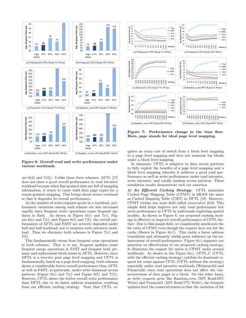
1) Overall Performance: Figure 6 illustrates overall per-formance of diverse FTLs under a variety of workloads. Wemeasure not only overhead of garbage collection and addresstranslation time but also system service time in order toevaluate overall performance including both read and writeperformance. Afterwards we will call the summation of theseaverage response time. An ideal pure page level mapping isselected as our baseline scheme.
As shown in Figure 6, overall performance of CFTL isvery close to that of an ideal page level mapping. That is,CFTL outperforms all the other FTLs in the lists in termsof both read and write performances under realistic work-loads as well as random workloads since read intensive work-load reflects well the read performance and write intensiveworkload the write performance. CFTL shows, in particu-lar, not only its better read performance against FAST [14]having strong point in read performance, but also write per-formance against DFTL [18] displaying the excellent writeperformance.
Figure 7 depicts the overall performance change of eachscheme as time flows and enables us to analyze these resultsin more detail. Under the read intensive access patterns(Figure 6(a) and 7(a), Figure 6(b) and 7(b), and Figure 6(d)and 7(d)), CFTL switches more and more data to a blocklevel mapping as time goes by in order to make the best ofits fast direct address translation. Moreover, the efficientcaching strategy makes a considerable effect on read perfor-mance since almost of the consecutive data pages in a datablock are not dispersed under the environment of the readintensive access patterns. In particular, as shown in Figure6(d), our proposed caching strategy exhibits its respectableeffectiveness in read performance especially under randomlyread intensive workloads. Compared to Figure 6(a), we canidentify the random read performance of most of the FTLsis significantly degraded. However, CFTL still shows itsgood random read performance due to the efficient cachingstrategy. We will discuss this in more detail in the next sub-section. As we expected, FAST which is hybrid mappingbut primarily based on a block level mapping also shows agood performance under the read intensive workloads. How-ever, it does not reach CFTL because of its intrinsic limi-tation such as merge operations even though there are notso many update operations in this workload. In additionto the expensive merge operations in FAST, extra read costin log blocks is also another factor to deteriorate its readperformance. DFTL is a two-tier pure page level mapping.If, however, the workload does not contain a high temporallocality, it frequently requires an additional overhead in ad-dress translation. This is the main cause that DFTL doesnot exhibit relatively good random read performance (Fig-
(a) Websearch3 (99% Read:1% Write) (b) Financial2 (82% Read:18% Write)
(c) Financial1 (23% Read:77% Write) (d) Random_read (99% Read:1% Write)
(e) Random_even (50% Read:50% Write) (f) Random_write (10% Read:90% Write)
25 26
34
30
50
20
25
30
35
40
45
50
Page
(ideal)
CFTL DFTL FAST AFTL
Av
g.
Re
spo
nse
Tim
e (
us)
56 58
74
129123
40
50
60
70
80
90
100
110
120
130
140
Page
(ideal)
CFTL DFTL FAST AFTL
Av
g.
Re
spo
nse
Tim
e (
us)
162185 192
507
334
100
150
200
250
300
350
400
450
500
Page
(ideal)
CFTL DFTL FAST AFTL
Av
g.
Re
spo
nse
Tim
e (
us)
25 27
51
39
20
30
40
50
60
70
80
Page
(ideal)
CFTL DFTL FAST AFTL
Av
g.
Re
spo
nse
Tim
e (
us)
116 122142
375
247
50
100
150
200
250
300
350
Page
(ideal)
CFTL DFTL FAST AFTL
Av
g.
Re
spo
nse
Tim
e (
us)
183 205 208
423
100
200
300
400
500
600
700
Page
(ideal)
CFTL DFTL FAST AFTL
Av
g.
Re
spo
nse
Tim
e (
us)
99
1068
Figure 6: Overall read and write performance undervarious workloads
ure 6(d) and 7(d)). Unlike these three schemes, AFTL [17]does not show a good overall performance in read intensiveworkload because when fine-grained slots are full of mappinginformation, it starts to cause valid data page copies for acoarse-grained mapping. This brings about severe overheadso that it degrades its overall performance.
As the number of write requests grows in a workload, per-formance variations among each scheme are also increasedrapidly since frequent write operations cause frequent up-dates in flash. As shown in Figure 6(c) and 7(c), Fig-ure 6(e) and 7(e), and Figure 6(f) and 7(f), the overall per-formances of AFTL and FAST are severely degraded underhalf and half workload, not to mention write intensive work-load. Thus we eliminate both schemes in Figure 7(c) and7(f).
This fundamentally stems from frequent erase operationsin both schemes. That is to say, frequent updates causefrequent merge operations in FAST and frequent both pri-mary and replacement block erases in AFTL. However, sinceDFTL is a two-tier pure page level mapping and CFTL isfundamentally based on a page level mapping, both schemesshows a considerably better overall performance than AFTLas well as FAST, in particular, under write dominant accesspatterns (Figure 6(c) and 7(c) and Figure 6(f) and 7(f)).However, CFTL shows the better overall write performancethan DFTL due to its faster address translation resultingfrom our efficient caching strategy. Note that CFTL re-
(e) Random_even (50% Read:50% Write) (f) Random_write (10% Read:90% Write)
Time(sec.)
20
25
30
35
40
45
50
55
10
30
50
70
90
110
130
150
170
190
400
1000
3000
Av
g.
Re
spo
nse
Tim
e (
us)
Time(sec.)
Page
CFTL
DFTL
FAST
AFTL
40
50
60
70
80
90
100
50
150
250
350
450
550
650
750
850
950
1050
1150
1250
1350
Av
g.
Re
spo
nse
Tim
e (
us)
Time(sec.)
Page
CFTL
DFTL
FAST
AFTL
100
150
200
250
300
100
1000
2000
3000
4000
5000
6000
7000
8000
9000
10000
11000
12000
13000
14000
Av
g.
Re
spo
nse
Tim
e(u
s)
Time(sec.)
Page
CFTL
DFTL
FAST
AFTL
100
110
120
130
140
150
160
170
180
190
200
1000
2000
3000
4000
5000
6000
7000
8000
9000
10000
11000
12000
13000
14000
Av
g.
Re
spo
nse
Tim
e(u
s)
Time(sec.)
Page
CFTL
DFTL
20
30
40
50
60
70
80
90
100
10
30
50
70
90
110
130
150
170
190
250
400
800
2000
Av
g.
Re
spo
nse
Tim
e (
us)
Time(sec.)
Page
CFTL
DFTL
FAST
AFTL
175
180
185
190
195
200
205
210
100
1000
2000
3000
4000
5000
6000
7000
8000
9000
10000
11000
12000
13000
14000
Av
g.
Re
spo
nse
Tim
e (
us)
Time(sec.)
Page
CFTL
DFTL
(a) Websearch3 (99% Read:1% Write) (b) Financial2 (82% Read:18% Write)
(c) Financial1 (23% Read:77% Write) (d) Random_read (99% Read:1% Write)
Figure 7: Performance change in the time flow.Here, page stands for ideal page level mapping.
quires no extra cost of switch from a block level mappingto a page level mapping and does not maintain log blocksunder a block level mapping.
In summary, CFTL is adaptive to data access patternsto fully exploit the benefits of a page level mapping and ablock level mapping whereby it achieves a good read per-formance as well as write performance under read intensive,write intensive, and totally random access patterns. Thesesimulation results demonstrate well our assertion.
2) An Efficient Caching Strategy: CFTL maintainsCached Page Mapping Table (CPMT) in SRAM the sameas Cached Mapping Table (CMT) in DFTL [18]. However,CPMT retains one more field called consecutive field. Thissimple field helps improve not only read performance butwrite performance in CFTL by judiciously exploiting spatiallocality. As shown in Figure 8, our proposed caching strat-egy is effective to improve overall performance of CFTL fur-ther. Due to this simple field, we considerably ameliorate thehit ratio of CPMT even though the request does not hit thecache (Shown in Figure 8(c)). This yields a faster addresstranslation and ultimately wields great influence on the en-hancement of overall performance. Figure 8(c) supports ourassertion on effectiveness of our proposed caching strategy.It illustrates the request hit ratios in CPMT under severalworkloads. As shown in the Figure 8(c), CFTL C (CFTLwith the efficient caching strategy) exhibits its dominant re-quest hit count against CFTL (CFTL without the strategy)especially under read intensive workloads (Websearch3 andFinancial2) since read operations does not affect the con-secutiveness of data pages in a block. On the other hand,as write requests grow like Random even (50% Read:50%Write) and Financial1 (23% Read:77% Write), the frequentupdates hurt the consecutiveness so that the variation of hit
(c) Request hit ratios in CPMT
(a) Read performance (b) Write performance
25
27
29
31
33
35
37
39
41
43
45
10
30
50
70
90
110
130
150
170
190
400
1000
3000
Av
g. R
esp
on
se T
ime
(u
s)
Time(sec.)
CFTL_C
CFTL
205
207
209
211
213
215
217
219
221
223
225
100
300
500
700
900
1100
1300
1500
1700
1900
2100
2300
2500
Av
g. R
esp
on
se T
ime
(us)
Time(sec.)
CFTL_C
CFTL
2.06
5.98
3.92
1.99
0.5
3.6 3.73
0.5
0
1
2
3
4
5
6
7
Websearch3 Random_even Financial1 Financial2
Hit
Ra
tio
(%
)
CFTL_C
CFTL
Figure 8: Performance improvement with efficientcaching strategy
counts between CFTL C and CFTL is relatively reduced.Figure 8(a) illustrates that both schemes converge on the
same average response time as time goes by. In other words,even though the CFTL does not have the efficient cachingstrategy, its read performance gradually approaches to thatof CFTL C as more and more requests come in. In our ex-periment, both read performances converge on the same per-formance after around 500 seconds corresponding to 104,420intensive read requests in this workload. Note that the con-vergence time totally depends on the types of workloads. Inother words, most of the read intensive data switch to a blocklevel mapping so that the read performance of CFTL grad-ually approaches to that of CFTL C after some time. Thisproves the adaptive feature of CFTL. However, CFTL Cexhibits its better read performance even before the read in-tensive data are converted to a block level mapping becauseit can considerably improve the hit ratio of CPMT even withthe same number of mapping table entries in SRAM. This isthe unique point of our proposed efficient caching strategyin CFTL scheme.
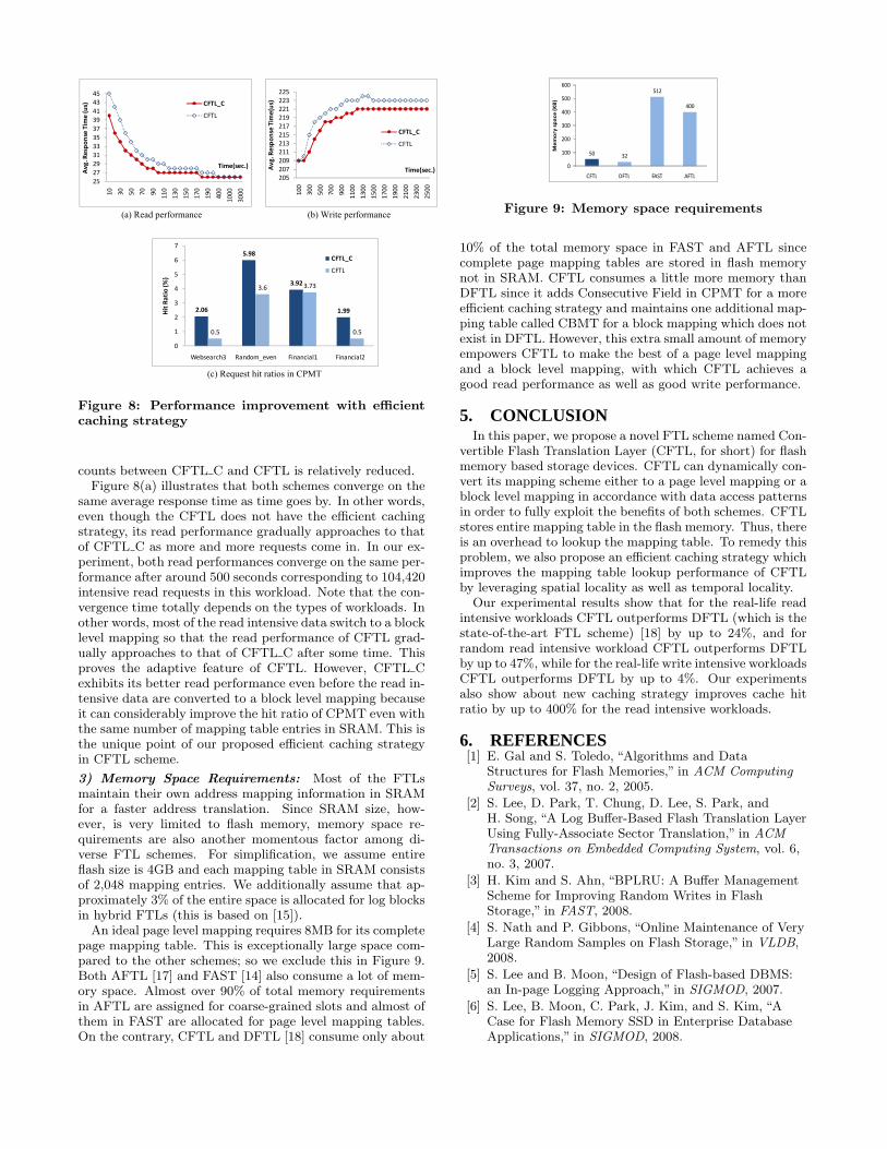
3) Memory Space Requirements: Most of the FTLsmaintain their own address mapping information in SRAMfor a faster address translation. Since SRAM size, how-ever, is very limited to flash memory, memory space re-quirements are also another momentous factor among di-verse FTL schemes. For simplification, we assume entireflash size is 4GB and each mapping table in SRAM consistsof 2,048 mapping entries. We additionally assume that ap-proximately 3% of the entire space is allocated for log blocksin hybrid FTLs (this is based on [15]).
An ideal page level mapping requires 8MB for its completepage mapping table. This is exceptionally large space com-pared to the other schemes; so we exclude this in Figure 9.Both AFTL [17] and FAST [14] also consume a lot of mem-ory space. Almost over 90% of total memory requirementsin AFTL are assigned for coarse-grained slots and almost ofthem in FAST are allocated for page level mapping tables.On the contrary, CFTL and DFTL [18] consume only about
5032
512
400
0
100
200
300
400
500
600
CFTL DFTL FAST AFTL
Me
mo
ry s
pa
ce
(K
B)
Figure 9: Memory space requirements
10% of the total memory space in FAST and AFTL sincecomplete page mapping tables are stored in flash memorynot in SRAM. CFTL consumes a little more memory thanDFTL since it adds Consecutive Field in CPMT for a moreefficient caching strategy and maintains one additional map-ping table called CBMT for a block mapping which does notexist in DFTL. However, this extra small amount of memoryempowers CFTL to make the best of a page level mappingand a block level mapping, with which CFTL achieves agood read performance as well as good write performance.
5. CONCLUSIONIn this paper, we propose a novel FTL scheme named Con-
vertible Flash Translation Layer (CFTL, for short) for flashmemory based storage devices. CFTL can dynamically con-vert its mapping scheme either to a page level mapping or ablock level mapping in accordance with data access patternsin order to fully exploit the benefits of both schemes. CFTLstores entire mapping table in the flash memory. Thus, thereis an overhead to lookup the mapping table. To remedy thisproblem, we also propose an efficient caching strategy whichimproves the mapping table lookup performance of CFTLby leveraging spatial locality as well as temporal locality.
Our experimental results show that for the real-life readintensive workloads CFTL outperforms DFTL (which is thestate-of-the-art FTL scheme) [18] by up to 24%, and forrandom read intensive workload CFTL outperforms DFTLby up to 47%, while for the real-life write intensive workloadsCFTL outperforms DFTL by up to 4%. Our experimentsalso show about new caching strategy improves cache hitratio by up to 400% for the read intensive workloads.
6. REFERENCES[1] E. Gal and S. Toledo, “Algorithms and Data
Structures for Flash Memories,” in ACM ComputingSurveys, vol. 37, no. 2, 2005.
[2] S. Lee, D. Park, T. Chung, D. Lee, S. Park, andH. Song, “A Log Buffer-Based Flash Translation LayerUsing Fully-Associate Sector Translation,” in ACMTransactions on Embedded Computing System, vol. 6,no. 3, 2007.
[3] H. Kim and S. Ahn, “BPLRU: A Buffer ManagementScheme for Improving Random Writes in FlashStorage,” in FAST, 2008.
[4] S. Nath and P. Gibbons, “Online Maintenance of VeryLarge Random Samples on Flash Storage,” in VLDB,2008.
[5] S. Lee and B. Moon, “Design of Flash-based DBMS:an In-page Logging Approach,” in SIGMOD, 2007.
[6] S. Lee, B. Moon, C. Park, J. Kim, and S. Kim, “ACase for Flash Memory SSD in Enterprise DatabaseApplications,” in SIGMOD, 2008.

[7] N. Agrawal, V. Prabhakaran, T. Wobber, J. Davis,M. Manasse, and R. Panigrahy, “Design Tradeoffs forSSD Performance,” in Usenix, 2008.
[8] M. Moshayedi and P. Wilkison, “Enterprise SSDs,”ACM Queue, vol. 6, no. 4, 2008.
[9] A. Leventhal, “Flash Storage Today,” Queue, vol. 6,no. 4, 2008.
[10] A. Caulfield, L. Grupp, and S. Swanson, “Gordon:Using Flash Memory to Build Fast, Power-efficientClusters for Data-intensive Applications,” in ASPLOS,2009.
[11] CompactFlashAssociation,“http://www.compactflash.org.”
[12] Jesung Kim and Jong Min Kim and Noh, S.H. andSang Lyul Min and Yookun Cho, “A space-efficientflash translation layer for compactflash systems,”IEEE Transactions on Consumer Electronics, 2002.
[13] T.-S. Chung, D.-J. Park, S. Park, D.-H. Lee, S.-W.Lee, and H.-J. Song, “A survey of Flash TranslationLayer,” J. Syst. Archit., vol. 55, no. 5-6, 2009.
[14] S.-W. Lee, D.-J. Park, T.-S. Chung, D.-H. Lee,S. Park, and H.-J. Song, “A Log Buffer-based FlashTranslation Layer Using Fully-associative SectorTranslation,” ACM Trans. Embed. Comput. Syst.,vol. 6, no. 3, 2007.
[15] J.-U. Kang, H. Jo, J.-S. Kim, and J. Lee, “ASuperblock-based Flash Translation Layer for NANDFlash Memory,” in EMSOFT, 2006.
[16] S. Lee, D. Shin, Y.-J. Kim, and J. Kim, “LAST:Locality-aware Sector Translation for NAND FlashMemory-based storage Systems,” SIGOPS Oper. Syst.Rev., vol. 42, no. 6, 2008.
[17] C.-H. Wu and T.-W. Kuo, “An adaptive two-levelmanagement for the flash translation layer ineembedded systems,” in ICCAD, 2006.
[18] A. Gupta, Y. Kim, and B. Urgaonkar, “Dftl: a flashtranslation layer employing demand-based selectivecaching of page-level address mappings,” in ASPLOS,2009.
[19] M-systems, “Two Technologies Compared: NOR vs.NAND,” White Paper, July 2003.
[20] A. Ban, “Flash File System,” United States of AmericaPatent 5 404 485, April 4, 1995.
[21] L.-P. Chang and T.-W. Kuo, “Efficient Managementfor Large-scale Flash Memory Storage Systems withResource Conservation,” in ACM Transactions onStorage, vol. 1, no. 4, 2005.
[22] J.-W. Hsieh, T.-W. Kuo, and L.-P. Chang, “EfficientIdentification of Hot Data for Flash Memory StorageSystems,” Trans. Storage, vol. 2, no. 1, 2006.
[23] L.-P. Chang and T.-W. Kuo, “An Adaptive StripingArchitecture for Flash Memory Storage Systems ofEmbedded Systems,” in RTAS, 2002.
[24] R. Karedla, J. S. Love, and B. G. Wherry, “CachingStrategies to Improve Disk System Performance,”Computer, vol. 27, no. 3, 1994.
[25] SamsungElectronics, “K9XXG08XXM Flash MemorySpecification,” 2007.
[26] “Websearch Trace from UMass Trace Repository,”http://traces.cs.umass.edu/index.php/Storage/Storage.
[27] “SPC: Storage Performance Council,”http://www.storageperformance.org.
[28] “OLTP Trace from UMass Trace Repository,” http://traces.cs.umass.edu/index.php/Storage/Storage.