Embed Size (px)
Citation preview

1 Robotic Aquovations
ABSTRACT
This technical report is meant to provide information pertaining to the underwater remotely
operated vehicle, Block-O-Bot, designed specifically for the 2013 Marine Advanced Technology
Education (MATE) Center International Competition. Block-O-Bot was designed, constructed
and tested by Robotic Aquovations in Columbus, Ohio. To create a reliable remotely operated
vehicle (ROV) for the client, MATE. Robotic Aquovations utilized the top engineers at the
company to create a completely unique ROV that caters toward all of the client’s requirements.
Block-O-Bot was designed to maintain functionality of the Regional Scale Nodes (RSN) cabled
observatory located off the coast of Washington and Oregon. Specific tasks the ROV can
perform include installing the Scientific Interface Assembly (SIA) into the Backbone Interface
Assembly (BIA) of a primary node, connecting the Cable Termination Assembly (CTA) into the
BIA, installing the secondary node and providing power and communications by connecting to
the SIA, installing a transmissometer created for optimal functionality by Robotic Aquovations,
removing and replacing an Acoustic Doppler Current Profiler (ADCP) from a water column
mooring, and ridding the site of dangerous biofouling.
The ROV has been equipped with four 19V DC thrusters, a multipurpose, actuating arm,
numerous cameras, a watertight, cylindrical electronics housing, ballast trim modules, and a
waterjet-cut aluminum frame. The control system is comprised of an Arduino Mega 2560, a
laptop computer, and a joystick. An Arduino was programmed with the Arduino language in
order to communicate with a computer. Block-O-Bot ROV emphasizes simplicity and
multipurpose use.
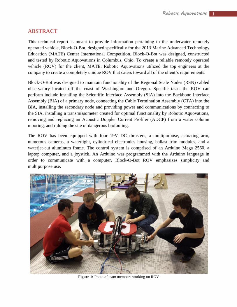
Figure 1: Photo of team members working on ROV
2 Robotic Aquovations
TABLE OF CONTENTS
Abstract 1
1. Budget 3
2. Design Rationale 6
2.1 Electronics Housing 6
2.2 Mounting Frame 7
2.3 Propulsion 7
2.4 Ballast Trim Modules 8
2.5 Claw - Gripping Mechanism 8
2.6 Measuring Device 8
2.7 Turbidity Sensor 8
2.8 Cameras 9
3. Electronics and Control 9
3.1 Surface Control System 9
3.2 Program Flow Chart 10
3.3 Tether 11
3.4 Power Conversion 11
3.5 Motor and Tool Package Control 11
3.6 Electrical Schematic 12
4. Challenges 13
5. Safety 14
6. Troubleshooting Techniques 14
7. Learning Experience 15
8. Future Improvements 15
9. Reflection 16
10. References 17
11. Acknowledgements 17
Appendix A – Code i

3 Robotic Aquovations
1. Budget
The following tables illustratate the overall budget and bill of materials for fabrication of Block-
O-Bot and travel associated with the 2013 MATE International ROV Competition.
Table 1: Budget for 2012-2013 Underwater Robotics Team
Complete 2012 - 2013 Budget Savings and Income
Saved and Incoming Funds (see sources of funding
for details)
$16,808.00
Materials
Expense Item Cost
ROV Materials and Fabrication
(see itemized bill of materials for details)
($6897.06)
Reserve Funds
Expense Item Cost
2013 Reserve Funds ($1,000.00)
Travel and Shipping
Expense Item Cost
Roundtrip Airfare ($4,512.00)
Tacoma Hotel Rooms ($1,380.40)
Transportation To/From Airport ($250.00)
Shipping Costs (ROV and Supplies roundtrip) ($600.00)
Total Costs $14,639.46
Budget Difference $2,168.54
Table 2: Sources of Funding
Source Amount
Funds saved from 2011-2012 1,956.00
Bonus funding earned through the College
of Engineering
1,042.00
Individual outside gifts 450.00
Engineers' Council 3,000.00
College of Engineering Matching funds 2,960.00
Team Member Contributions 2,400.00
Battelle Grant 5,000.00
Total 16,808.00

4 Robotic Aquovations
Qty. Item Unit
Cost
Total
Cost Per
Item
Wire Connectors
1 10-pin connector Inline (MCIL10M) $59.50 $59.50
1 10-pin connector Bulk Head (MCBH10F) $89.60 $89.60
1 3-pin connector Inline (MCIL3M) $23.66 $23.66
1 3-pin connector Bulk Head (MCBH3F) $45.89 $45.89
1 12-pin connector Inline (MCIL12M) $66.50 $66.50
1 12-pin connector Bulk Head (MCBH12F) $103.39 $103.39
4 4-pin connectors Inline (MCIL4M ) $28.98 $115.92
4 4-pin connectors Bulk Head (MCBH4F) $52.85 $211.40
1 High Power 4-contact Inline (HPIL4M, ) $106.54 $106.54
1 High Power 4-contact Bulk Head (HPBH4F) $169.20 $169.20
1 Subconn Connector Freight $25.00 $25.00
1 Dow Corning Molykote 44 Grease, 5.3 oz tube (suggested grease for
connectors)
$26.95 $26.95
1 Loctite 222 10 mL bottle $12.75 $12.75
2 Ultra-Clear Tygon PVC Tubing 3/4'' ID, 1'' OD (1 foot length) $6.10 $12.20
2 Underwater Silicone Sealant (2.8 oz tube) $6.06 $12.12
Propulsion & Control
4 Seabotix BTD 150 ROV Thrusters $695.00 $2,808.25
1 SeaMATE Controller Board $340.00 $340.00
1 Arduino Mega 2560 $64.99 $64.99
3 Sabertooth 2x12 Motor Controller $79.99 $239.97
2 Zahn DC/DC Converter (48V to 24V) $99.00 $198.00
1 Murata DC/DC Converter (48V to 12V) $44.74 $44.74
Frame
1 36" x 24" Al-6061 sheet, 0.25" thick $130.00 $130.00
1 2.5"x4"x12" UHMW Polyethylene $52.86 $52.86
1 8ft 1"x1", .25'' thick, Al 6061 T6 90 deg Angle $13.49 $13.49
1 4ft 1"x1" Al 6061 T6 90 deg Angle $7.71 $7.71
2 .125" thick, 12"x12" Virgin Plastic NATURAL Sheet UHMW $4.40 $8.80
2 2"x2" Easy-to-Machine Chemical-Resistant Polypropylene (1 foot) $11.02
Arm Assembly
1 6"x24" 304 SS McMaster #9085K41 (arm support) $32.29 $32.29
1 1 1/4" Thick, 2.5"x12" White Delrin $27.75 $27.75
1 .5"x4"x12" Easy-to-Machine Impact-Resistant ABS $8.78 $8.78
1 1"x2"x12" white delrin $19.03 $19.03
1 2"x2"x12" white delrin $33.54 $33.54
1 .25"x20 , 8" length (10/pack) Al-6061 $12.25 $12.25
1 18-8 SS .25-20 Hex Nut (100/box) $4.57 $4.57
Table 3: Itemized Bill of Materials

5 Robotic Aquovations
1 Nylon Unthreaded Round Spacer 1/2" OD, 11/16" Length, 1/4"
Screw Size
$9.70 $9.70
1 1/4"-20, 1/2 long, SS Socket Head Cap (50 per box) $6.68 $6.68
1 Worm and Worm Gear (Boston Gears) $56.00 $56.00
1 18-8 Stainless Steel Socket Head Cap Screw, 1/4"-20 Thread, 4"
Length, packs of 10
$7.37 $7.37
1 High-Strength Aluminum (Alloy 2024), Tight Tolerance, 3/16"
Diameter, 1' Length
$4.14 $4.14
1 Alloy Steel .001" Oversized Dowel Pin, 1/16" Diameter, 3/4"
Length, packs of 25
$8.37 $8.37
1 Corrosion Resistant Dowel Pin, Type 316 Stainless Steel, 3/32"
Diameter, 3/4" Length
$7.68 $7.68
1 Brass Standard Key Stock, 1/8" X 1/8", 12" Length $1.78 $1.78
1 Fully Keyed Aluminum Drive Shaft, 1/2" OD, 1/8" Keyway Width,
6" Length
$12.69 $12.69
1 White Delrin (R) Acetal Resin Rectangular Bar, 1-1/2" Thick X 3"
Width, 1' Length
$37.20 $37.20
Electronic Materials
1 Black PVC Heat-Shrink Tubing $19.66 $19.66
Electronics Housing
2 Super-Grip Black Nylon Cinching Straps 2'' wide 36'' long $11.63 $23.26
2 Aluminum 6061-T651 PLate .25'' thick, 8''X8'' $9.18 $18.36
1 Aluminum 6061-T6 PLate .125'' thick, 12''X12'' $14.53 $14.53
1 Impact-Resistant Slippery UHMW Polyethylene 5'' Rod 1 foot long $44.10 $44.10
Cameras
2 !nventivity Color Cameras $29.50 $59.00
Light Opacity Module
1 Electrical components (CDS Cell, resistors) $5.00 $5.00
1 2-13/16" Width, 1-5/8" High, Brown, Push-to-Open Grab Latch $6.90 $6.90
Mission Props
1 PVC pipe materials $140.00 $140.00
1 Various small items (hinges, nuts, bolts, rope) $30.00 $30.00
Team Apparel
1 Competition team polo shirts $300.00 $300.00
Administration
1 Reimbursement $380.00 $380.00
1 Team Registration $100.00 $100.00
36 Pool Time $13.25 $477.00
Total
Cost: $6,897.06

6 Robotic Aquovations
2. Design Rationale
Block-O-Bot was designed to efficiently incorporate all required tool packages and remain
flexible for possible modifications if needed. The final design resulted from integrating the
following systems: electronics housing, mounting frame, ballast trim modules, and a
multipurpose gripping mechanism. During the design phase, focus was placed on watertight
sealing, versatile tool packages, optimal camera placement and buoyancy. All of the ROV
components were modeled using the computer aided design (CAD) software package
SolidWorksTM
2012 to ensure compatibility among all designed parts.
2.1 Electronics Housing
The housing is a cylindrical, watertight container composed of mostly acrylic (see Figure 2).
The main segments are end caps, sealing collars, electronic control compartment, central
connection hub, and power conversion compartment.
The end caps are located at either side of the housing and are used for internal electrical
component repair and modifications. They are bolted to the ends of the housing with a rubber
gasket between the cap and the sealing collar for a watertight seal.
The sealing collars were created to achieve maximum
gasket surface area. The collars were chemically bonded
to the electronic control compartment and power
conversion compartment by applying a solvent to the
acrylic.
The electrical control compartment contains the Arduino
Mega 2560 microcontroller and three Sabertooth motor
controllers. These components are mounted on an
aluminum plate that is constrained with two cylindrical
end pieces made of Delrin®.
The central connection hub provides a large area for
mounting seven SubConn® watertight bulkhead
connectors. These connectors are used for inputting
power, communicating to the surface, motor control, and
camera signal and power. The acrylic was threaded and
a flat surface was machined for each connector to ensure
a leak-proof seal. The central position of the hub allows
for easy wire access to both sides of the housing.
The power conversion compartment is similar to the
electronic control compartment except that it contains
two Zahn 48V to 24V and one 48V to 12V DC/DC
converters.
Figure 2: Photo of electronics housing with
labels.
Electronic Control
Compartment
Central
Connection Hub
Power Conversion
Compartment
Sealing Collar
End Cap

7 Robotic Aquovations
2.2 Mounting Frame
The mounting frame was designed to provide secure positions for each subsystem (propulsion,
buoyancy, tool packages, and control). The frame consists of
the base plate, electronics housing mounts, and the buoyancy
structure (see Figure 3).
The base plate was constructed with a 6061-aluminum alloy
sheet. The aluminum sheet was cut using a waterjet which
provided a finished product to the exact specifications of the
design. Several gaps were created in the base plate to supply
adequate water flow around the ROV and propulsion system.
Mounting holes for low tolerance subsystems were cut using
the waterjet to guarantee correct placement. To prevent damage
to the robot, four supports were mounted to the bottom of the
base plate and rubber edging was placed on the aluminum
perimeter.
The electronics housing mounts act as cradles for the
cylindrical structure and preserve the orientation of the housing.
Rubber pads were glued to the surface that is in contact with the
electronics housing to prevent slippage or
rotation. To secure the housing to the base
plate, Velcro straps fasten to the base,
pressing the cylindrical housing onto the
mounts (see Figure 4).
The buoyancy structure was designed to
secure two pieces of high density foam to
the top of the ROV. The foam forms the
shape of an Ohio State Block O and is used
to maintain neutral buoyancy while
underwater. The structure consists of four
rectangular assemblies, placed on the right
and left sides of the electronics housing. The
structure was assembled with 90 degree
angle aluminum extrusions and stainless
steel nuts and bolts.
2.3 Propulsion
The ROV is driven by four 19V Seabotix BTD150
thrusters (see Figure 5). The configuration of the
thrusters allows for vertical motion (Z-axis) and
unrestricted motion in the horizontal plane (X-Y-
plane). The speed of the motors is controlled by
utilizing pulse width modulation to vary the voltage
that is supplied to the thruster. When running at 19V
each thruster draws a maximum continuous amperage
Figure 3: Waterjet base plate
Buoyancy Structure
Housing Mounts “Cradles”
Base Plate
Bottom Support “Foot”
(4 total)
Figure 4: SolidworksTM
model of mounting frame
Figure 5: Photo of Seabotix thruster
(Image from Seabotix.com)

8 Robotic Aquovations
of 4.25 A and provides a continual bollard thrust of 2.2 kgf.
2.4 Ballast Trim Modules
The ballast trim modules (see Figure 6) allow for fine balance
control to calibrate the center of gravity and to account for varying
buoyancy changes across multiple water environments. Adding
small weights to the trim modules is more effective than modifying
the amount or placement of the high density foam. The volume of
high density foam attached to the top of the ROV was designed to
be slightly high to account for the use of the ballast trim modules.
Each module is composed of a PVC cap, plug, and coupling. The
combination of these items produces a closed cylindrical
compartment capable of storing a certain volume of weight.
2.5 Claw- Gripping Mechanism The arm and claw was designed as an adaptable multipurpose tool (see Figure 7). An axle and
gear assembly at the rear of the claw drives the arm vertically for fine tune adjustments. The
claw and arm is constructed of mostly stainless
steel sheet metal, Delrin®, and ultra-high-
molecular-weight polyethylene. The stainless
steel components were laser cut and the plastic
pieces were machined with a mill, band saw, and
lathe. The claw is opened and closed with a
threaded rod powered by a 12V Johnson bilge
pump cartridge. A threaded slider is driven back
and forth across the rod and forces two linkages
to open and close the claw. The vertical actuation
is powered by another 12V Johnson bilge pump
which rotates a worm gear system. The arm and
claw is mounted beneath the base plate,
protruding past the front perimeter. The claw is
utilized to complete the following tasks:
Installing SIA into BIA, inserting CTA into the bulkhead connector on the BIA, releasing the
secondary node via pin, removing secondary node from elevator, installing secondary node in
designated location, leveling out secondary node, opening door of BIA, installing secondary
node cable connector into SIA, installing turbidity sensor, disconnecting power to mooring
platform, unlocking hatch, opening hatch, removing ADCP from the mooring platform, installing
replacement ADCP, closing hatch, re-locking hatch, reconnecting power to mooring platform,
and removing biofouling. Block-O-Bot's claw and arm is a genuine multipurpose tool.
2.6 Measuring Device
To accurately measure the distance from the BIA to the designated location for secondary node
placement, a retractable tape measure was modified with a large hook on the end to attach to the
BIA. To view the measurement a camera was placed above the device. The text on the tape
measure was also enlarged for easy viewing by the camera.
Figure 7: Photo of horizontal claw
Figure 6: Ballast trim modules
9 Robotic Aquovations
2.7 Turbidity Sensor
The turbidity sensor consists of a 28,500 mcd white LED, and a cadmium sulfide photo resistor.
The photo resistor is connected from ground to an analog pin on an Arduino UNO located on the
surface. The UNO has firmware identical to the Arduino Mega located in Block-O-Bot via the
software Processing. Processing graphs the values returned on the screen.
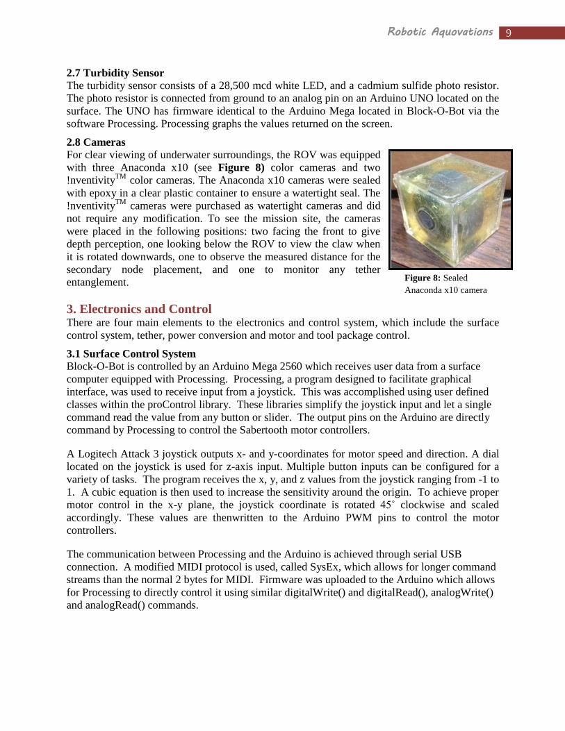
2.8 Cameras
For clear viewing of underwater surroundings, the ROV was equipped
with three Anaconda x10 (see Figure 8) color cameras and two
!nventivityTM
color cameras. The Anaconda x10 cameras were sealed
with epoxy in a clear plastic container to ensure a watertight seal. The
!nventivityTM
cameras were purchased as watertight cameras and did
not require any modification. To see the mission site, the cameras
were placed in the following positions: two facing the front to give
depth perception, one looking below the ROV to view the claw when
it is rotated downwards, one to observe the measured distance for the
secondary node placement, and one to monitor any tether
entanglement.
3. Electronics and Control There are four main elements to the electronics and control system, which include the surface
control system, tether, power conversion and motor and tool package control.
3.1 Surface Control System
Block-O-Bot is controlled by an Arduino Mega 2560 which receives user data from a surface
computer equipped with Processing. Processing, a program designed to facilitate graphical
interface, was used to receive input from a joystick. This was accomplished using user defined
classes within the proControl library. These libraries simplify the joystick input and let a single
command read the value from any button or slider. The output pins on the Arduino are directly
command by Processing to control the Sabertooth motor controllers.
A Logitech Attack 3 joystick outputs x- and y-coordinates for motor speed and direction. A dial
located on the joystick is used for z-axis input. Multiple button inputs can be configured for a
variety of tasks. The program receives the x, y, and z values from the joystick ranging from -1 to
1. A cubic equation is then used to increase the sensitivity around the origin. To achieve proper
motor control in the x-y plane, the joystick coordinate is rotated 45˚ clockwise and scaled
accordingly. These values are thenwritten to the Arduino PWM pins to control the motor
controllers.
The communication between Processing and the Arduino is achieved through serial USB
connection. A modified MIDI protocol is used, called SysEx, which allows for longer command
streams than the normal 2 bytes for MIDI. Firmware was uploaded to the Arduino which allows
for Processing to directly control it using similar digitalWrite() and digitalRead(), analogWrite()
and analogRead() commands.
Figure 8: Sealed
Anaconda x10 camera

10 Robotic Aquovations
3.2 Program Flow Chart
The control program logic is shown in Figure 9.
Figure 9: Program flow chart

11 Robotic Aquovations
3.3 Tether
The tether supplies Block-O-Bot with power and offers communication and camera video signal
between the ROV and the surface control system. Power is sent to the ROV with two speaker
cables, and communication and camera video signal are accomplished with two cat 5e cables.
Communication between the surface control system and the ROV requires USB extenders for
data communication through the 30 meter CAT 5e.
3.4 Power Conversion
The provided 48V is converted to voltages of 24V and
12V to power thrusters, tool packages, Arduino
microcontroller, and cameras. To convert from 48V to
24V, two Zahn DC/DC converters (see Figure 10)
were used which could each supply a maximum
amperage of 15 A. The horizontal thrusters and are
powered by the first Zahn converter and the vertical
motors and claw are powered by the second converter.
A 48V to 12V Murata DC/DC converter supplies
power to the Arduino microcontroller and the
cameras.
3.5 Motor and Tool Package Control
The thrusters and tool packages are controlled through the surface control system by a joystick.
The Arduino microcontroller receives PWM output values from the program and sends these
signals to the Sabertooth motor controllers. The Sabertooth motor controllers drive the Seabotix
thrusters and claw assembly. The Sabertooth motor controller has several modes which make
them a flexible component that could be used for other purposes in the future. The analog mode
was utilized for its simple input signal requirements. In analog mode, the Sabertooth motor
controllers convert the input signal to an output voltage for each motor based on a signal range of
0V to 5V, where 0V indicates full negative
power, 2.5V indicates power off, and 5V
indicates full positive power. This is an easy
signal to acquire from the joystick output values.
Once the Arduino microcontroller receives the
PWM signal from the surface control system,
the signal is reproduced through a digital output
pin. In order to transform the PWM signal into
an analog signal, an RC filter was used (see
Figure 11). The filter smoothes out the digital
PWM signal into the desired analog signal.
Figure 10: Photo of Zahn DC/DC converter
(http://www.zahninc.com/sd1xspec4824280.html)
Figure 11: Diagram of PWM to analog filter

12 Robotic Aquovations
3.6 Electrical Schematic
The electrical schematic is shown in Figure 12.
Figure 12: Electrical Schematic

13 Robotic Aquovations
4. Challenges The ROV team at Ohio State and Robotic Aquovations is still a young, up and coming student
group that might seem slightly misplaced at a school whose engineering project teams are
dominated by well-established motorsport projects. The team has been in existence for less than
three years and in that time the company's two foremost challenges have been to build a
sustainable budget and expand team knowledge of ROV design. The team's ROV designs in each
of the past three years have been a reflection of its growth in both those areas. Each work day has
been a learning experience that has only bettered the team.
Specifically, waterproofing has and will remain a challenge, but the Block-O-Bot's watertight
electronics housing is a major redesign from last year that has proven to be a wonderful success.
The previous year's housing was unique in that it was a low profile, lightweight, carbon fiber
design that, unfortunately, leaked like a sieve despite its “cool” factor. The housing was formed
by a mold that disallowed the necessary surface flatness required to press against custom seal
block o-rings for wire passage. The team realized the housing's fundamental engineering flaw
and created the current cylinder
design. The redesign has proven to
be a great success in protecting its
critical electronic cargo.
Electronic control system design
has proven to be another challenge
for the team because of its many
mechanically minded individuals.
The team has been working to
recruit electrical and computer
science engineering members, but
in the meantime, the group has
been required to step outside its
comfort zone to formulate an
effective, albeit simple, electronic
and control system. Several
systems have been utilized,
including the SeaMATE control
board and a fair share of Arduino
based control methods using both
Playstation 3 controllers and a
joystick. The team has seen
connection time outs, communication losses, bad MOSFET transistors, and an exploding
capacitor. Despite the team's electronic tribulations and need for more electronically skilled
members, we continued to learn, adapt, and emphasize safety. Block-O-Bot's final control
system has been reliable and a product of tremendous growth.
One challenge for a young, self-taught ROV team is to recognize and deal with haunting
mistakes of its much less experienced past. These are mistakes that do not immediately reveal
themselves, but that with time, can create real setbacks. Young mistakes from more than a year
Figure 13: Intact photo of ROV

14 Robotic Aquovations
ago finally revealed their damage in the original, reused tether. A water leak was discovered in
the communication line that most likely occurred at some point in the last year or before. The
only sign of past cable leakage was wire corrosion discovered this May. Capillary effects carried
the corrosion throughout lengthy sections of cable. A new tether with new wiring was required
and the situation was once again a learning experience to pass down to future members. In all the
team's challenges the most important thing was to learn and adapt. Mistakes occur when a team
is learning the ropes and building its skills. At the same time, underwater ROVs present a unique
set of inherent challenges. It is the duty for current team members to pass down their lessons
learned and to continue growth in the team's overall skills, knowledge, and experience.
5. Safety An important aspect of any engineering project is safety. To make the Block-O-Bot as safe as
possible several techniques and procedures were implemented. Due to the risks associated with
throwing an electronic filled capsule into a five meter deep pool, the selection of components
was essential. The Sabertooth motor controllers used have over-current and thermal protection,
along with large heat sinks attached to either side. In case of a motor stall, the controllers would
be left unharmed, and potential component damage would be averted. Heating of the components
in general was also a safety concern. The components are designed to function within a certain
temperature range, and if they are subjected to extreme heat, they could release smoke or cause a
loss of control of the motors. To combat this, proper heat sinking was employed by mounting
components to aluminum plates to facilitate heat conduction. A fan circulates air through the
housing, and extensive testing was completed to conclude that heat was managed within required
limits.
A 20 amp circuit breaker is used to quickly turn on and off power and to ensure that current
levels remain low. Inline fuses are used within the electronics housing to protect cameras and
limit current draw from potentially hazardous power converters. Since communication loss is a
possibility, the control program was modified to shut off power to thrusters while there is no user
input. If communication was lost, Block-O-Bot would not damage itself, nearby divers, or other
ROVs. Any live power situation required procedural "all clear", "power on", and "power off" call
outs.
Exterior safety mechanisms include simple alterations to the ROV structure to make the vehicle
safe for handlers and divers. Rubber edging was placed around the perimeter of the ROV for safe
handling and to prevent injury. The thrusters are shrouded, and caution labels are present to
prevent accidental injury. Additional labeling warns against any hazardous machine elements in
the robotic arm.
6. Troubleshooting Techniques In order to effectively troubleshoot problems, the company found it best to test individual
components or variable in a systematic manner. One of the biggest problems encountered was
that the control board would lose communication with the surface at seemingly random times. In
order to solve this problem, steps were taken to first ensure that all wiring on the ROV was
correctly implemented and that the program had no obvious flaws. After no issues were found,
the tether was examined and it was discovered that the control board would lose communication
at varying tether positions. Further examination showed physical wear to the communication
cabling and new communication wire was installed. Further tests showed continued
communication issues at times, and by eliminating most other possible problems, it was

15 Robotic Aquovations
concluded that the communication issues were also caused, in part, by electromagnetic
interference (EMI). The tether was remade to reduce the effects of EMI and successfully solve
the communication issues.
The team has been able to troubleshoot and solve arising problems by systematically testing any
possible cause of error. Although this process can be time consuming, it has proven to be the
most effective way to narrow down the source of any problem.
7. Learning Experience The experience of building Block-O-Bot taught the team many important skills, the most
important of which were teamwork and time management. Many in the group had never worked
with engineers outside of their discipline. This project taught those members critical, real world
skills needed to combine electrical and mechanical engineering training into the creation of a
professional end product. Team members learned how to better communicate across varying
technical levels to collaborate and achieve design goals. Knowledge of time management skills
were also imparted to the team
particularly concerning a build
schedule. The team has learned how to
better project time requirements for
post-production testing, control system
creation, and debugging. Part of the
engineering design process is to
carefully plan required deadlines for
each step of a long term project, and
the team will certainly better utilize
tools such as Gantt charts to improve
future time budgeting. From tether
damage, communication issues, and
time budgeting, the team has learned
many lessons the hard way, but
sometimes learning the hard way has
the greatest impact while striving for
future improvement.
8. Future Improvements As a growing engineering project team it is our intention to continue our understanding of ROVs,
electrical and mechanical design, and team working strategies. In the future we hope to increase
the sophistication of the control system which will allow for increased safety features and
implementation of temperature and pressure sensors.
Another vital matter concerns recruitment. This year’s team is quite small and those who are
greatly involved include a narrow range of majors. To increase the knowledge base our team
utilizes to design and build, it is our goal to reach out to the engineering majors such as computer
science and electrical engineering.
An additional objective for the team is to educate our peers and prospective engineering students
about the importance of underwater technology. By holding public events with the ROV, we can
Figure 14: Photo of ROV during pool testing
16 Robotic Aquovations
stimulate young minds and educate the community about what the oceans have to offer this
world.
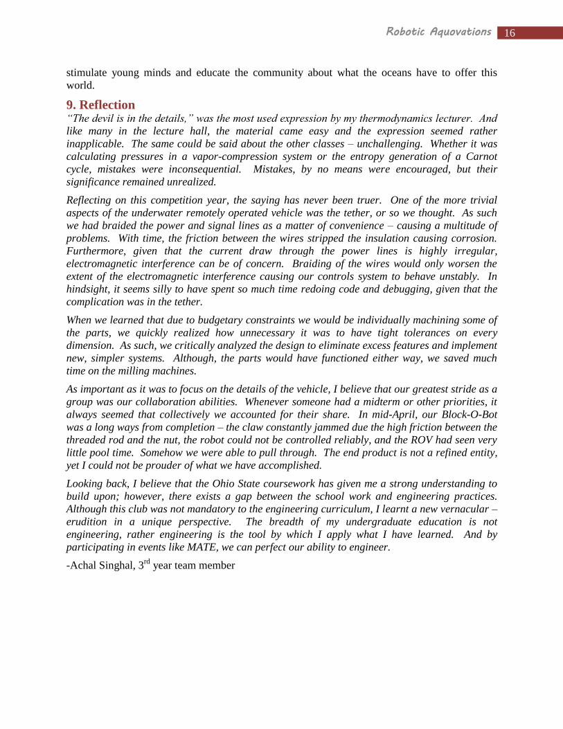
9. Reflection “The devil is in the details,” was the most used expression by my thermodynamics lecturer. And
like many in the lecture hall, the material came easy and the expression seemed rather
inapplicable. The same could be said about the other classes – unchallenging. Whether it was
calculating pressures in a vapor-compression system or the entropy generation of a Carnot
cycle, mistakes were inconsequential. Mistakes, by no means were encouraged, but their
significance remained unrealized.
Reflecting on this competition year, the saying has never been truer. One of the more trivial
aspects of the underwater remotely operated vehicle was the tether, or so we thought. As such
we had braided the power and signal lines as a matter of convenience – causing a multitude of
problems. With time, the friction between the wires stripped the insulation causing corrosion.
Furthermore, given that the current draw through the power lines is highly irregular,
electromagnetic interference can be of concern. Braiding of the wires would only worsen the
extent of the electromagnetic interference causing our controls system to behave unstably. In
hindsight, it seems silly to have spent so much time redoing code and debugging, given that the
complication was in the tether.
When we learned that due to budgetary constraints we would be individually machining some of
the parts, we quickly realized how unnecessary it was to have tight tolerances on every
dimension. As such, we critically analyzed the design to eliminate excess features and implement
new, simpler systems. Although, the parts would have functioned either way, we saved much
time on the milling machines.
As important as it was to focus on the details of the vehicle, I believe that our greatest stride as a
group was our collaboration abilities. Whenever someone had a midterm or other priorities, it
always seemed that collectively we accounted for their share. In mid-April, our Block-O-Bot
was a long ways from completion – the claw constantly jammed due the high friction between the
threaded rod and the nut, the robot could not be controlled reliably, and the ROV had seen very
little pool time. Somehow we were able to pull through. The end product is not a refined entity,
yet I could not be prouder of what we have accomplished.
Looking back, I believe that the Ohio State coursework has given me a strong understanding to
build upon; however, there exists a gap between the school work and engineering practices.
Although this club was not mandatory to the engineering curriculum, I learnt a new vernacular –
erudition in a unique perspective. The breadth of my undergraduate education is not
engineering, rather engineering is the tool by which I apply what I have learned. And by
participating in events like MATE, we can perfect our ability to engineer.
-Achal Singhal, 3rd
year team member

17 Robotic Aquovations
10. References Collins, J. A., Henry R. Busby, and George H. Staab. Mechanical Design of Machine Elements
and Machines: A Failure Prevention Perspective. Hoboken, NJ: Wiley, 2010. Print.
Moore, Steven W., Harry Bohm, and Vickie Jensen. Underwater Robotics: Science, Design &
Fabrication. Monterey, CA: Marine Advanced Technology Education (MATE) Center,
2010. Print.
11. Acknowledgements None of this would have been possible without the tremendous help of the following people and
organizations:
MATE, for giving us the opportunity to design and construct an underwater ROV for an
international competition.
Battelle Memorial Institute, for a grant and mentorship that made the construction of the
ROV possible
Paul Green, for the donation of materials and electronics housing machining assistance
Center for Automotive Research (CAR), for giving us a space in the engineering project
team workshop
The Ohio State College of Engineering, for funds and for giving us the knowledge to
create the ROV
Shawna Fletcher, for being a great faculty advisor and supporter for the team
Fred Donelson, for his time and hospitality at Gahanna Lincoln's Lake Robo
Nathan Vaughn, for his time and assistance with electronics and controls
The Pittro and Roan families, for support and a monetary donation

i Robotic Aquovations
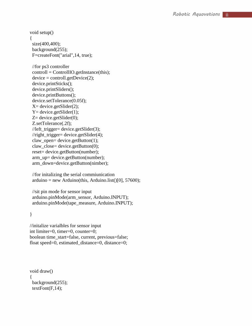
Appendix A – Code
ROV Control Code
//set the target distance for task 1
float target_distance=_________;
//arduino motor ports and constants
int LH=2;
int V=3;
int RH=4;
int clawpin=6;
int armpin=7
int max_volts=229;
int min_volts=26;
float a=.3;
// sensor prots
int arm_sensor=1;
int tape_measure=5;
//libraries and classes for PS3 controller
import procontroll.*;
import java.io.*;
ControllIO controll;
ControllDevice device;
ControllSlider Y;
ControllSlider X;
ControllSlider Z;
ControllButton arm_up;
ControllButton arm_down;
ControllButton claw_open;
ControllButton claw_close;
ControllButton reset;
//libraries and classes for the Arduino firmata
import processing.serial.*;
import cc.arduino.*;
Arduino arduino;
PFont F;
int xvar=500;
ii Robotic Aquovations
void setup()
{
size(400,400);
background(255);
F=createFont("arial",14, true);
//for ps3 controller
controll = ControllIO.getInstance(this);
device = controll.getDevice(2);
device.printSticks();
device.printSliders();
device.printButtons();
device.setTolerance(0.05f);
X= device.getSlider(2);
Y= device.getSlider(1);
Z= device.getSlider(0);
Z.setTolerance(.2f);
//left_trigger= device.getSlider(3);
//right_trigger= device.getSlider(4);
claw_open= device.getButton(1);
claw_close= device.getButton(0);
reset= device.getButton(number);
arm_up= device.getButton(number);
arm_down=device.getButton(nimber);
//for initalizing the serial commiunication
arduino = new Arduino(this, Arduino.list()[0], 57600);
//sit pin mode for sensor input
arduino.pinMode(arm_sensor, Arduino.INPUT);
arduino.pinMode(tape_measure, Arduino.INPUT);
}
//initalize varialbles for sensor input
int limiter=0, timer=0, counter=0;
boolean time_start=false, current, previous=false;
float speed=0, estimated_distance=0, distance=0;
void draw()
{
background(255);
textFont(F,14);

iii Robotic Aquovations
fill(0);
//************get values from PS3 Controller*************
float X_val=X.getValue();
float Y_val=Y.getValue();
float Z_val=0-Z.getValue();
text("X-value:",20,40);
text(X_val,75,40);
text("Y-value:",20,60);
text(Y_val,75,60);
text("Z-value:",20,80);
text(Z_val,75,80);
Y_val=-1*Y_val;
X_val=X_val*X_val*X_val*a+(1-a)*X_val;
Y_val=Y_val*Y_val*Y_val*a+(1-a)*Y_val;
Z_val=Z_val*Z_val*Z_val*a+(1-a)*Z_val;
//X_val=128*X_val+128;
//Y_val=128*Y_val+128;
//rotate axis
float x_prime, y_prime;
x_prime = (X_val+Y_val)*.707;
y_prime = (Y_val-X_val)*.707;
int right1, left1, right2, left2, rightout, leftout;
/*
right1=int(255-Y_val);
left1=int(255-Y_val);
right2=int(255-X_val);
left2=int(X_val);
rightout=(right1+right2)/2+5;
leftout=(left1+left2)/2+5;
*/
//*********control right and left motors***********
rightout=int(128*y_prime+132);
leftout=int(128*x_prime+132);
//prevents glitch
if (rightout>max_volts)
{

iv Robotic Aquovations
rightout=max_volts;
}
else if (rightout<min_volts)
{
rightout=min_volts;
}
if (leftout>max_volts)
{
leftout=max_volts;
}
else if (leftout<min_volts)
{
leftout=min_volts;
}
//write output to pin
arduino.analogWrite(RH, rightout);
arduino.analogWrite(LH, leftout);
text("right out: "+rightout,20,140);
text("left out: "+leftout,20, 160);
//***************Vertical Motors*******************
int Zout;
Zout=int(map(Z_val,-1,1,25,230))+5;
if (Zout>max_volts)
{
Zout=max_volts;
}
else if (Zout<min_volts)
{
Zout=min_volts;
}
arduino.analogWrite(V, Zout);
text("Vertical: "+Zout,20,180);
//*******************claw control********************
int claw;
if(claw_close.pressed())
{
claw=84;
}
v Robotic Aquovations
else if(claw_open.pressed())
{
claw=172;
}
else
{
claw=132;
}
arduino.analogWrite(clawpin, claw);
text("Claw: "+claw,20,200);
//*************arm control*****************
if(arm_up.pressed())
{
arm=84;
}
else if (arm_down.pressed())
{
arm=172;
}
else
{
arm=132;
}
arduino.analogWrite(armpin, arm);
//visual interface
line(300, 150, 300, rightout-28+50);
line(290, 150, 290, (rightout-28+50)*.9+15);
line(310, 150, 310, (rightout-28+50)*.9+15);
line(200, 150, 200, leftout-28+50);
line(190, 150, 190, (leftout-28+50)*.9+15);
line(210, 150, 210, (leftout-28+50)*.9+15);
line(300,rightout-28+50,290,(rightout-28+50)*.9+15);
line(300,rightout-28+50,310,(rightout-28+50)*.9+15);
line(200,leftout-28+50,210,(leftout-28+50)*.9+15);
line(200,leftout-28+50,190,(leftout-28+50)*.9+15);
//**********sensor input**********
//for arm motion

vi Robotic Aquovations
if (arduino.digitalRead(arm_sensor)== Arduino.HIGH)
{
text("ARM OUT OF RANGE",20,120);
if(arm_direction)
}
//for tape measure
if (reset.pressed())
{
distance_counter=0;
speed=0;
}
current=(arduino.digitalRead(tape_measure)==Arduino.HIGH);
if((current != previous)&&(limiter==0))
{
distance_counter++;
limiter=1;
time_start=false;
timer=0;
}
else if ((current != previous)&&(limiter==1))
{
limiter=0;
time_start=true;
}
previous=current;
if(time_start)
{
timer++;
}
else if(!time_start)
{
speed=6./float(timer);
}
estimated_distance=speed*float(timer);
if(estimated_distance>6.0)
{
estimated_distance=6.0;
}
distance=float(distance_counter)*6.0+estimated_distance;

vii Robotic Aquovations
text("tape measure: "+distance,20,220);
if (distance>(target_distance-1))&&(counter<600))
{
text("OPEN CLAW!!",20,240);
counter++;
}
}
Turbidity Sensor Code
import processing.serial.*;
import cc.arduino.*;
Arduino arduino;
PFont F;
void setup() {
size(1550, 250);
frameRate(50);
arduino = new Arduino(this, Arduino.list()[0], 57600);
F=createFont("arial",14, true);
textFont(F, 14);
fill(0);
background(255);
line(25,200,1525,200);
line(25,0,25,200);
pushMatrix();
rotate(PI/2);
text("Turbidity",50,-10);
popMatrix();
line(325,200,325,210);
text("1 Min",315,230);
line(625,200,625,210);
text("2 Min",615,230);
line(925,200,925,210);
text("3 Min",915,230);
line(1225,200,1225,210);
text("4 Min",1215,230);
line(1525,200,1525,210);
text("5 Min",1515,230);

viii Robotic Aquovations
F=createFont("arial",14, true);
arduino.pinMode(5,Arduino.OUTPUT);
arduino.digitalWrite(5, Arduino.HIGH);
}
int n=249, k, l;
float value, previous_value;
void draw() {
textFont(F, 14);
fill(255);
n++;
rect(95,210,40,20);
fill(0);
text(arduino.analogRead(1),100,225);
k=n/10;
l=(n-1)/10;
value=map(arduino.analogRead(1),0,750,200,0);
line(l,previous_value,k,value);
previous_value=value;
if( k>1525)
{
saveFrame();
background(255);
n=249;
background(255);
line(25,200,1525,200);
line(25,0,25,200);
pushMatrix();
rotate(PI/2);
text("Turbidity",50,-10);
popMatrix();
line(325,200,325,210);
text("1 Min",315,230);
line(625,200,625,210);
text("2 Min",615,230);
line(925,200,925,210);
text("3 Min",915,230);
line(1225,200,1225,210);
text("4 Min",1215,230);
line(1525,200,1525,210);
text("5 Min",1515,230);
}
}