Embed Size (px)
Citation preview
I. Report No. 2. Government Accession No.
FHW A/TX-99/1811-S
4. Title and Subtitle
EVALUATION AND MODIFICATION OF SIGHT DISTANCE CRITERIA USED BY TxDOT
7. Author(s)
Mark D. Wooldridge, Angelia H. Parham, Kay Fitzpatrick, R. Lewis Nowlin, and Robert E. Brydia
9. Performing Organization Name and Address
Texas Transportation Institute The Texas A&M University System College Station, Texas 77843-3135
12. Sponsoring Agency Name and Address
Texas Department of Transportation Research and Technology Transfer Office P.O. Box 5080 Austin, Texas 78763-5080
15. Supplementary Notes
Technical Report Documentation Page
3. Recipient's Catalog No.
5. Report Date
September 1998
6. Performing Organization Code
8. Performing Organization Report No.
Project Summary Report 1811-S
10. Work Unit No. (TRAIS)
11. Contract or Grant No.
Proiect No. 0-1811
13. Type of Report and Period Covered
Project Summary: September 1997 - August 1998
14. Sponsoring Agency Code
Research performed in cooperation with the Texas Department of Transportation and the U.S. Department of Transportation, Federal Highway Administration. Research Project Title: Develop and Evaluate Sight Distance Criteria at Intersections, Interchanges, and Ramps
16. Abstract
Sight distance is an important consideration in roadway design, affecting many aspects of highway safety and operations. Ramp, interchange, and intersection designs are typically completed in tightly constrained spaces with many structural, earthwork, and roadway features present that may obstruct sight distance. These features are not easily moved; if consideration of sight distance constraints is not given early in the design process, designs may be compromised and a reduced level of safety may be encountered by the public on the completed roadway. After conducting a literature review of design criteria, three case studies of interchange ramps, and a thorough review of the TxDOT Design Division Operations and Procedures Manual, the authors recommended revisions for the manual. These revisions include material intended to clarify and extend the consideration of sight distance in roadway design.
17. KeyWords Ramp Design, Sight Distance Criteria, Stopping Sight Distance, Decision Sight Distance, Intersection Sight Distance
18. Distribution Statement No restrictions. This document is available to the public through NTIS: National Technical Information Service 5285 Port Royal Road Springfield, Virginia 22161
19. Security Classif. (of this report) Unclassified
20. Security Classif. (of this page) Unclassified
21. No. of Pages 22. Price 50
FormDOTF 1700.7 (8-72)


EVALUATION AND MODIFICATION OF SIGHT DISTANCE CRITERIA USED BY TxDOT
by
Mark D. Wooldridge, P.E. Assistant Research Engineer
Texas Transportation Institute
Angelia H. Parham, P .E. Assistant Research Engineer
Texas Transportation Institute
Kay Fitzpatrick, P.E. Associate Research Engineer Texas Transportation Institute
R. Lewis Nowlin Formerly Assistant Research Scientist
Texas Transportation Institute
and
Robert E. Brydia Assistant Research Scientist
Texas Transportation Institute
Report 1811-S Project Number 0-1881
Research Project Title: Develop and Evaluate Sight Distance Criteria at Intersections, Interchanges, and Ramps
Sponsored by the Texas Department of Transportation
In Cooperation with U.S. Department of Transportation Federal Highway Administration
September 1998
TEXAS TRANSPORTATION INSTITUTE The Texas A&M University System College Station, Texas 77843-3135


IMPLEMENTATION RECOMMENDATIONS
1. The report provides proposed revisions to the TxDOT Design Division Operations and
Procedures Manual (herein referred to as the Design Manual). The authors recommend that
these revisions be incorporated into the Design Manual so that they become effective when
the next edition of the Design Manual is published.
2. Existing TxDOT training courses may also be used to inform designers of the proposed
changes to the Design Manual.
Pagev


DISCLAIMER
The contents of this report reflect the views of the authors, who are responsible for the facts
and accuracy of the data presented herein. The contents do not necessarily reflect the official views
or policies of the Texas Department of Transportation (TxDOT) or the Federal Highway
Administration (FHW A). This report does not constitute a standard, specification, or regulation, nor
is it intended for construction, bidding, or permit purposes. This report was prepared by Mark D.
Wooldridge (TX-65791), Angelia H. Parham (TN-100,307), Kay Fitzpatrick (PA-037730-E), R.
Lewis Nowlin, and Robert E. Brydia.
Page vii

ACKNOWLEDGMENT
The project team recognizes Robert B. Stone, project director; Alvin Krejci, Jr., program
coordinator; and project advisors Wesley M. Burford, Robert E. Leahey, and Gus Shanine for their
time in providing direction and comments for this study. This study was performed in cooperation
with the Texas Department of Transportation and the U.S. Department of Transportation, Federal
Highway Administration.
The authors would also like to recognize the following persons for he1ping with data
collection, data analysis, and report preparation efforts: Abishai Polus, Molly Marshall, Shirley
Kalinec, Jon Collins, and Kollan Pillay.
Page viii

TABLE OF CONTENTS
1 INTRODUCTION .................................................... 1-1
2 LITERATURE REVIEW . . . . . . . . . . . . . . . . . . . . . . . . . . . . . . . . . . . . . . . . . . . . . . 2-1
STOPPING SIGHT DISTANCE ........................................ 2-1
DECISION SIGHT DISTANCE ........................................ 2-5
INTERSECTION SIGHT DISTANCE ................................... 2-7
RAMP MERGE SIGHT DISTANCE ................................... 2-10
3 RAMP CASE STUDIES ............................................... 3-1
CASE STUDY A ............ .,. . . . . . . . . . . . . . . . . . . . . . . . . . . . . . . . . . . . . . . 3-1
CASE STUDY B ...................................................... 3-3
CONCLUSION ...................................................... 3-6
4 RECOMMENDATIONS FOR IMPLEMENTATION ...................... 4-1
BASIC DESIGN CRITERIA, DESIGN ELEMENTS:
Sight Distance .................................................. 4-2
Sight Distance, Stopping Sight Distance ............................ 4-2
Sight Distance, Decision Sight Distance ............................. 4-4
Sight Distance, Intersection Sight Distance .......................... 4-5
Sight Distance, Sight Distance on Horizontal Curves .................. 4-7
NEW LOCATION AND RECONSTRUCTION (4R) DESIGN CRITERIA:
URBAN STREETS, Intersections ................................ 4-10
TWO-LANE RURAL HIGHWAYS, Intersections .................. 4-11
MULTILANE RURAL HIGHWAYS, Intersections ................. 4-12
FREEWAYS .................................................. 4-13
Page ix

TABLE OF CONTENTS CONTINUED
FREEWAYS, Sight Distance .................................... 4-14
LONGITUDINAL BARRIERS, CONCRETE BARRIERS, LOCATION ..... 4-15
REFERENCES ............................................................. R-1
Pagex

CHAPTERl
INTRODUCTION
Providing adequate sight distance on a roadway is one of the central tasks of the designer.
Adequate sight distance provides motorists with the opportunity to avoid obstacles on the roadway,
to merge smoothly with other traffic, and to traverse intersections safely. Ramp, interchange, and
intersection designs are typically completed in tightly constrained spaces with many structural,
earthwork, and roadway elements present that may obstruct sight distance. These elements are not
easily moved; if consideration to sight distance constraints is not given early in the design process,
designs may be compromised and may reduce the level of safety on the completed roadway. To
facilitate the completion of satisfactory roadway designs, sight distance criteria must be presented
in a clear, comprehensive, and unambiguous manner.
The authors first completed a literature review to examine the development of relevant sight
distance criteria. Understanding why various criteria were developed and implemented provided a
background necessary for the clear understanding of various sight distance equations and
recommendations. The review of actual field locations with poor sight distance problems provided
a necessary understanding of challenges encountered in design. The authors completed three case
studies in the project, examining available sight distance at three different sites. Finally, they
reviewed material currently in TxDOT's Highway Design Division Operations and Procedures
Manuaz<n (herein referred to as the Design Manual) and recommended modifications.
The objectives of this project were to evaluate the sight distance guidelines contained in the
Design Manual and improve or modify those guidelines where necessary. The authors placed an
emphasis on ramp design in particular, although they also evaluated other sight distance criteria and
recommended modifications.
This report provides a review of stopping sight distance, intersection sight distance, decision
sight distance, and ramp merge sight distance. Recommended changes to the Design Manual
centered around updating design values, including additional references to sight distance, and
providing additional design tools to help review available sight distance in the design process.
Page 1-1

Evaluation and Modification of Sight Distance Criteria Used by TxDOT
This report is organized into four chapters. Chapter 1 provides background material for the
research, with the literature review presented in Chapter 2. Findings from the three case studies are
in Chapter 3, and Chapter 4 presents the recommended changes to the Design Manual.
Page 1-2

CHAPTER2
LITERATURE REVIEW
The review of sight distance criteria in the literature focused around three sight distance
requirements that frequently apply to various situations encountered in design:
• Stopping sight distance;
• Decision sight distance; and
• Intersection sight distance.
In addition, a fourth category was investigated: ramp merge sight distance. Only a limited amount
of literature was available regarding this final topic.
STOPPING SIGHT DISTANCE
According to the American Association of State Highways and Transportation Officials
(AASHTO)A Policy on Geometric Design of Highways and Streef2) (herein referred to as the Green
Book), sight distance is the length of roadway ahead that is visible to the driver. The Green Book
also states that the minimum sight distance at any point on the roadway should be long enough to
enable a vehicle traveling at or near the design speed to stop before reaching a stationary object in
its path. Although greater length is desirable, sight distance at every point along the highway should
be at least that required for a below average driver or vehicle to stop in this distance. The NCHRP
(National Cooperative Research Program) recently sponsored a study on stopping sight distanceY>
Most of the following material was obtained from the project's reports.
AASHTO Stopping Sight Distance Model Equations
Stopping sight distances are calculated using basic principles of physics and the relationships
between various design parameters. The 1994 Green Boo1C2> defines stopping sight distance as the
sum of two components: brake reaction distance (distance traveled from the instant the driver
detects an object to the instant the brakes are applied) and the braking distance (distance traveled
Page 2-1

Evaluation and Modification of Sight Distance Criteria Used by TxDOT
from the instant the driver applies the brakes to when the vehicle decelerates to a stop).(2J Minimum
and desirable stopping sight distances are calculated with the following equation:
SSD = BrakeReactionDistance +Braking Distance
SSD "° 0.278Vt +
where: SSD = stopping sight distance, m;
y2
254[
V = design or initial speed, km/h;
t = driver perception-reaction time, s; and
f friction between the tires and the pavement surface.
(2-1)
(2-2)
The minimum length of vertical curves is controlled by the required stopping sight distance,
driver eye height, and object height. This required length of curve is such that, at a minimum, the
stopping sight distance calculated is available at all points along the curve. Where an object off the
pavement such as a bridge pier, bridge railing, median barrier, building, cut slope, or natural growth
restricts sight distance, the required offset to that obstruction is determined by the stopping sight
distance.
Most people agree that the AASHTO stopping sight distance model results in well-designed
roads, i.e., roads that are safe, efficient, and economical. If so, why develop a revised model? The
need for a revised model has been defined elsewhere<4> as follows:
Page 2-2
• The current stopping model was based on common sense, engineering judgment, and the
laws of physics; however, the parameters within the model are not representative of the
driving environment. Thus, the parameters are difficult to justify, validate, and/or
defend.
• It has never been established on the basis of data that the provision of longer stopping
sight distance results in fewer accidents. Conversely, it has never been established on
the basis of data that at least for marginal reductions, provision of shorter stopping sight
distance results in more accidents.

Chapter 2 - Literature Review
As noted, the major criticism of the current model is that its parameters are not representative
of the driving environment or safe driving behavior. Thus, although its use results in a good design,
it is difficult to justify, validate, and defend as a good model. As a result of these difficulties, a
recent NCHRP project recommended a relatively simple driver performance based mode1<3> as a
replacement for the current Green Book modeI.<2> The recommended model is as follows:
SSD=0.218Vt+ o.o39vz a
where: SSD = stopping sight distance, m;
V = initial speed, km/h;
t driver perception-brake P~action time, s; and
a driver deceleration, m/s2·
(2-3}
An implicit assumption of a driver performance stopping sight distance model is that the
tire/pavement friction must meet or exceed the driver's demands for stopping.
For consistency, it was recommended that the parameters within the recommended stopping
sight distance model represent common percentile values from the underlying probability
distributions. Specifically, 9ffh (or 10th} percentile values are recommended for design. The resultant
values are as follows:
• One design speed and stopping sight distance;
• Perception-brake reaction time-2.5 s;
• Driver deceleration- 3.4 m/s2;
• Driver eye height-1080 mm; and
• Object height-600 mm.
The new model results in stopping sight distances, sag vertical curve lengths, and lateral
clearances between the current minimum and desirable requirements. Crest vertical curve lengths
are shorter than current minimum requirements using the new SSD model. (See Figure 2-1 and
Table 2-1.)
Page 2-3

Evaluation and Modification of Sight Distance Criteria Used by TxDOT
E ti !.) c
~ i5 :i: Cl ;; Cl c a Q.
~
150
100
50
0
0 20 40 60 ao 100
Initial Speed, km/h
Figure 2-1. Comparison of 1994 AASHTO and Recommended Values for Stopping Sight Distance<3l
Table 2-1. Recommended Stopping Sight Distances for Design<3>
120
Stopping
Initial Perception-Brake Reaction Braking Sight Distance
Speed Deceleration Distance
(km/h) Time (s) Distance (m) (m/s2) (m)
Page 2-4
30 2.5 20.8 3.4 10.2
40 2.5 27.8 3.4 18.2
50 2.5 34.7 3.4 28.4
60 2.5 41.7 3.4 40.8
70 2.5 48.6 3.4 55.6
80 2.5 55.6 3.4 72.6
Note: Shading represents sight distances that are beyond most drivers' visual capabilities for detecting small and/or low contrast objects.
for Design
(m)
31.0
45.9
63.1
82.5
104.2

Chapter 2 - Literature Review
DECISION SIGHT DISTANCE
The concept of decision sight distance (DSD) was first addressed in a 1966 paper by
Gordon. <5l In his paper, Gordon talked about the concept of "perceptual anticipation". The concern
was that the existing stopping sight distance values were too short for situations that required high
decision complexity. Building on Gordon's argument, Leisch studied this concept further and
defined the term "anticipatory sight distance."<6> This distance provides the necessary time for
drivers to anticipate changes in design features (such as intersections, interchanges, lane drops, etc.)
or a potential hazard in the roadway and perform the necessary maneuvers.
A 197 5 study by Alexander and Lunenfeld<7J defined the term "decision sight distance" as
follows:
" .. the distance at which drivers can detect a hazard or a signal in a cluttered
roadway environment, recognize it or its potential threat, select an
appropriate speed and path, and perform the required action safely and
efficiently."
A 1978 FHW A study by McGee et al. developed guidelines on DSD values.<8l
Recommended values for DSD were developed based on the hazard-avoidance model. Previous
research efforts<9•10
•1 n developed and modified this model which consists of the following six
variables:
1. Sighting: Baseline time point at which the hazard is within the driver's sight line;
2. Detection: Time for driver's eyes to fixate on the hazard;
3. Recognition: Time for brain to translate image and recognize hazard;
4. Decision: Time for driver to analyze alternative courses and select one;
5. Response: Time for driver to initiate response; and
6. Maneuver: Time for driver to accomplish a change in path and/or speed.
Adding the above variables determines the total time required from the moment that the hazard is
visible to completion of the maneuver. The results from the study by McGee et al. were used to
develop recommended DSD values based on the design speed of the roadway. The
recommendations were adopted and introduced in the 1984 AASHTO Green Book.(12)
Page 2-5

Evaluation and Modification of Sight Distance Criteria Used by TxDOT
Current Guidelines in Green Book
Because the initial guidelines presented in the 1984 Green Book were vague and difficult to
apply, the guidelines were updated in the 1990 Green BoofC13l and remained unchanged in the 1994
revision.<2l
In the 1994 Green Book,<2> decision sight distance is defined as follows:
" ... distance required for a driver to detect an unexpected or otherwise
difficult-to-perceive information source or hazard in a roadway environment
that may be visually cluttered, recognize the hazard or its potential threat,
select an appropriate speed and path, and initiate and complete the required
safety maneuver safel~' and efficiently."
The Green Book<2> recommends that DSD be provided when drivers must make complex or
instantaneous decisions, when information is difficult to perceive, or when unexpected or unusual
maneuvers are required. Examples of critical locations where DSD should be considered are:
• Interchange and intersection locations where unusual or unexpected maneuvers are
required;
• Changes in cross section such as toll plazas and lane drops; and
• Areas of concentrated demand where there is apt to be "visual noise" whenever sources
of information such as those from roadway elements, traffic, traffic control devices, and
advertising signs compete.
Recommended values for DSD are shown in Table 2-2. These values are substantially
greater than stopping sight distance because of the additional time allowed to maneuver a vehicle.
The recommendations in Table 2-2 are based on the location of the road (urban, suburban, or rural)
and on the type of maneuver required (change speed, path, or direction). As shown in this table,
shorter DSD values are required for rural roads and when a stop maneuver is involved.
Page 2-6

Chapter 2 - Literature Review
Table 2-2. Recommended Decision Sight Distance Values in the 1994 Green Book(2l
Design Decision Sight Distance for Avoidance Maneuver (m)1
Speed A B c D E
(km/h)
50 75 160 145 160 200
60 95 205 175 205 235
70 125 250 200 240 275
80 155 300 230 275 315
90 ] 85 360 275 320 360
100 225 415 315 365 405
110 265 455 335 390 435
120 305 505 375 415 470
1 A: Stop on rural road D: Speed/path/direction change on suburban road B: Stop on urban road E: Speed/path/direction change on urban road C: Speed/path/direction change on rural road
INTERSECTION SIGHT DISTANCE
At-grade intersections have long been a focal point for vehicle conflict. Since the first days
of geometric design, the crossing of two roadways has necessitated a compromise between mobility
and safety. Over time, formal guidelines for establishing clear sight requirements at intersections
have evolved. Developed by AASHO (American Association of State Highway Officials) and later
AASHTO (American Association of State Highway and Transportation Officials), these guidelines
outline the procedures and requirements necessary for the establishment of safe distances that allow
vehicles approaching an intersection either to regulate their speeds such that safe passage across the
intersection is achieved by both vehicles or to effect regulatory control on the minor roadway by
requiring vehicles to stop and proceed when the major roadway is clear.
The first formal presentation of Intersection Sight Distance (ISD) requirements appeared in
the 1940 AASHO publication "A Policy on Intersections at Grade."U4l This initial discussion
contained procedures for three general classifications of intersections. Over the next five decades,
subsequent publications furthered the concept of intersection sight distance and refined the clear
Page 2-7

Evaluation and Modification of Sight Distance Criteria Used by TxDOT
sight requirements. The 1990 Green Boo~3J included four cases for ISD procedures, and the 1994
Green Book<2J added an additional case of vehicles turning left off of the major road onto the minor
road for a total of five cases.
The basis of all Green Book(2J intersection sight distance requirements is stopping sight
distance which was detailed earlier in this report. A vehicle approaching an intersection has the
choice of accelerating, slowing, or stopping, depending on the intersection control. The application
of intersection sight distance is discussed with regard to a sight triangle, which is a mechanism for
applying sight distance along each leg of an intersection. A sight triangle is simply an unobstructed
distance along both roadways and across the included corner for a specified distance which should
be kept clear of any sight obstructions. A brief discussion of each case in the 1994 policy follows.
Case I
As presented in the original 1940 policy, the concept of a Case I intersection is to allow the
drivers of the vehicles to regulate their speeds such that safe passage across the intersection is
achieved by both vehicles. That means that the driver of the vehicle has to be able to see an
approaching vehicle along the other leg of the sight triangle and moderate his speed accordingly.
Case II
In contrast to Case I, where the concept is to allow vehicle operators to control their speed,
Case II is designed to allow the vehicle on the major road to continue at its current speed without
stopping. The vehicle on the minor road should regulate its speed and decelerate to a full stop. In
order to come to a complete stop, stopping sight distance must be provided along the minor road.
Case III
Case ill ISD is applicable when there is a stop sign on the minor road. In this situation the
minor road vehicle must be able to see for a sufficient distance along the major roadway for the
stopped vehicle to start moving and clear the intersection. The time required to clear the intersection
is dependent on the perception time, the time required to engage the vehicle, and the time required
to accelerate across the intersection.
Page 2-8

Chapter 2 - Literature Review
Case IV
AASHO publications previous to 1957 did not discuss signalized intersections. The first
reference of this situation was acknowledged and then dismissed by stating that normal ISD
requirements are not necessary at signalized intersections.
The 1984 Green Book!J2l gives the first discussion of the Case IV condition by stating that
due to the operational considerations inherent at an intersection operated by signalized control, Case
ill sight distances should be available to the driver. The supporting evidence for this argument is
that increased hazards at the intersection warrant this distance, particularly in the event of failure of
the signal, violations of the signal, or other possibilities such as right turns on red. Neither the 1990
or 1994 policies furthered the 1984 discussions.
CaseV
The 1994 Green Boo~2l contained the first writeup for vehicles stopped on the major road
and turning left onto the minor road. Labeled as Case V, the driver turning left must be able to see
a sufficient distance ahead to tum left and clear the opposite lane before a vehicle in that lane reaches
the intersection.
Recent Study
In an attempt to answer many of the questions concerning intersection sight distance, such
as what are the appropriate methodologies and parameter values, the National Cooperative Highway
Research Program (NCHRP) funded a study on ISD which concluded in 1996. The explicit goal of
this project was to examine the current AASHTO methodology and recommend new or revised
models and/or parameters for Cases I through V. Published in 1996, the final report(l7J made the
following recommendations:
• Case I rationale should be changed to allow both vehicles the opportunity to stop rather
than adjusting speed because adjusting speed requires both drivers to take the correct
action. A new model was formulated which accounts for this change.
Page 2-9

Evaluation and Modification of Sight Distance Criteria Used by TxDOT
• Case II recommended ISD values are longer than current AASHTO values to a driver
approaching a yield-controlled intersection greater flexibility over a stop-controlled
intersection.
•Case III methodology is recommended to use gap acceptance. The standard length of the
departure sight triangle along the major road was recommended to be 7 .5 seconds for
passenger car vehicles, 9.5 seconds for single unit trucks, and 11.5 seconds for combination
trucks. The length of the departure sight triangle on the minor road was 4.4 m.
• Case IV sight distance follows the new values and the gap acceptance methodology
recommended for Case III. When signals are to be placed on flashing operation for low
volume periods, the departure sight triangles for Case III operations should be provided.
Where right-tum-on-red operations are allowed, the Case III departure sight triangle for
right turns must be provided.
• Case V operations are to be modeled on gap acceptanr:e operations and inc1ude
adjustments for the number of lanes to be crossed.
RAMP MERGE SIGHT DISTANCE
In a 1960 study, Pinne11U5) reviewed entrance ramp characteristics and investigated sight
distance. According to Pinnell, drivers exhibit a more desirable entrance ramp behavior when
provided adequate sight distance to the main lanes. When drivers were provided with a view of the
main-lane vehicles from 200 feet upstream of the ramp nose, the drivers were able to merge with low
relative speed differentials between their vehicles and the vehicles on the main lanes. This view
allows the drivers to adjust their speed to provide entry to a suitable gap in the traffic. Another
examination of sight distance required on an entrance ramp was completed by BhiseU6) in 1973.
Although the study was oriented towards vehicle design and the constraints placed on drivers by roof
pillars and other vehicle obstructions, the performance of the test drivers was monitored on a wide
variety of ramps. In this study, the search and scan behavior of drivers on on-ramps was monitored
with an eye-mark camera system. Drivers on the ramps were observed to be actively searching for
main-lane vehicles as much as 10 seconds prior to the ramp nose. A recommendation was made that
drivers be able to observe traffic on the main lanes for 10 seconds prior to and after the nose of the
ramp. This study was very limited in scope, however, and the findings were based on data from four
young male drivers only.
Page 2-10

CHAPTER3
RAMP CASE STUDIES
Sight distance restrictions in freeway interchanges can be problematic because of the
likelihood of high traffic volumes and highly restrictive design environments. Ramps geometries
are typically at or very near minimum design values because of the high cost of right-of-way (ROW)
and the high cost of providing bridge structures. Providing a ramp designed at minimum values is
not problematic in and of itself because of the large factors of safety generally present in even a
"minimum" level design. Challenges may arise, however, if safety or operational improvements are
needed because the same restrictions present in the original design (plus, perhaps, restrictions present
as a result of new structures built or proposed for construction subsequently) prevent easy
modifications.
To gain additional information regarding "typical" sight distance impediments in the urban
environment, the researchers undertook three field investigations. These investigations focused on
on-ramps with sight distance limitations.
CASE STUDY A
The first case study was a direct-connect ramp at an urban interchange of two access
controlled freeways. A photograph of the ramp, designed in 1987, is shown in Figure 3-1. The
design, constrained by the complex geometry inherent in a multilevel urban interchange, is bordered
by a retaining wall on the inside of the curve. Other aspects of the ramp are typical of a high
standard interchange: concrete barriers, metal beam guard fence, and safety end treatments are
provided at obstacles and dropoffs; drainage details and cut- and fill-slopes appear to be acceptable;
and vertical curvature rates are relatively modest.
The horizontal curve radius and offset distance were reviewed to evaluate available sight
distance on the ramp. The applicable sight distance criteria is stopping sight distance (SSD), which
should be provided at every point along an alignment. The value of SSD used, however, is
contingent on the design speed selected for use by the designer. Three different values for design
speed are suggested in the 1994 Green Bookf.2l and the Design Manua[,U> representing various
percentages of the design speed on the connecting highway. These values are characterized as upper
Page 3-1

Chapter 3 - Ramp Case Studies
range (85 percent), middle range (70 percent), and lower range (50 percent). Although the exact
design speeds actually used by the designers on the connecting highways were not available,
desirable (1J0 km/h) and minimum (80 km/h) design speeds used by TxDOT for controlled access
facilities were used for the purposes of this analysis. The minimum and desirable offset distances
were calculated using the minimum desirable SSD for the various design speed values.
Figure 3-1. Case Study A: Direct Connect Ramp
Comparing the measured offset to calculated offset distances that represent a range of design
speeds, researchers found that the site provided sight distance adequate for a design speed of 60
km/h. This design speed, however, met the "middle range" requirement when the minimum main
lane design speed (80 km/h) was used as a basis for the ramp design speed, and it met the "lower
range" requirement when the desirable main-lane design speed (110 km/h) was used as the basis for
the ramp design speed.
Although design speed and the appropriateness of the design criteria shown in the 1994
Green BoofC..2> and the Design ManuafU) are outside the bounds of this study, it appears that the use
of the lower range design speed would be questionable in this case. If this lower range design speed
were used for design purposes, however, the available sight distance on the ramp provided by the
offset (7 .62 m) would exceed the offsets calculated using both minimum and desirable SSD
requirements (3.69 and 4.78 m, respectively). To provide a frame ofreference for the ramp, a spot
speed study was conducted to determine the operating speed on the ramp. Speeds of free-flow
Page 3-2

Evaluation and Modification of Sight Distance Criteria Used by TxDOT
vehicles were measured in approximately the middle of the ramp. The measured offset distance
corresponds to a design speed of 60 km/h which was roughly the 3rct percentile operating speed on
the facility.
The middle range design speed based on a design speed of 110 km/h on the main lanes
corresponded to approximately the 85th percentile speed. This speed appears to represent a more
realistic design condition in this case. For example, an offset calculated using desirable SSD
requirements would exceed that value available by 5.26 m; however, calculated using minimum SSD
requirements, the offset would exceed that width available by only by 0.85 m.
Ramp and direct connection shoulder width design values used by TxDOTU> provide a total
shoulder width of 2.4 to 3.6 m, allowing motorists to bypass stalled vehicles on one-lane ramps. An
alternative design solution to this existing ramp could be to provide a narrower outside shoulder and
correspondingly wider inside shoulder, providing the additional 0.85 m offset. This would provide
greater sight distance and still prrmit bypassing stalled '·ehicles on the ramp.
CASESTUDYB
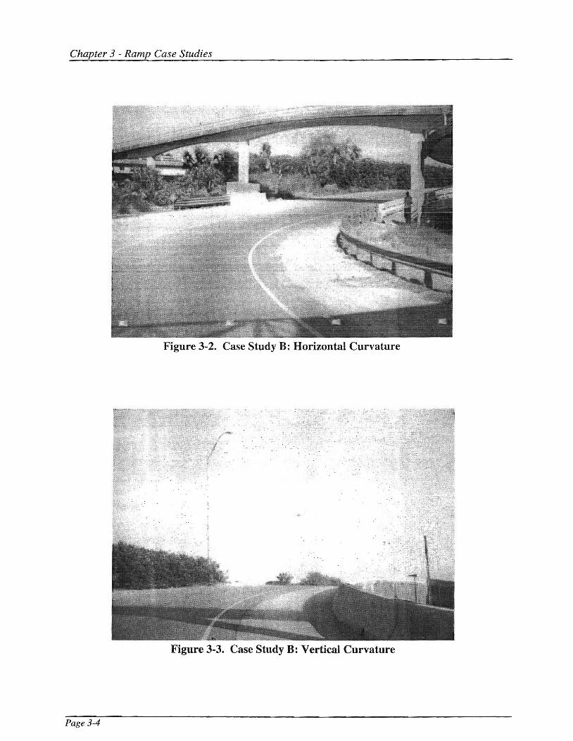
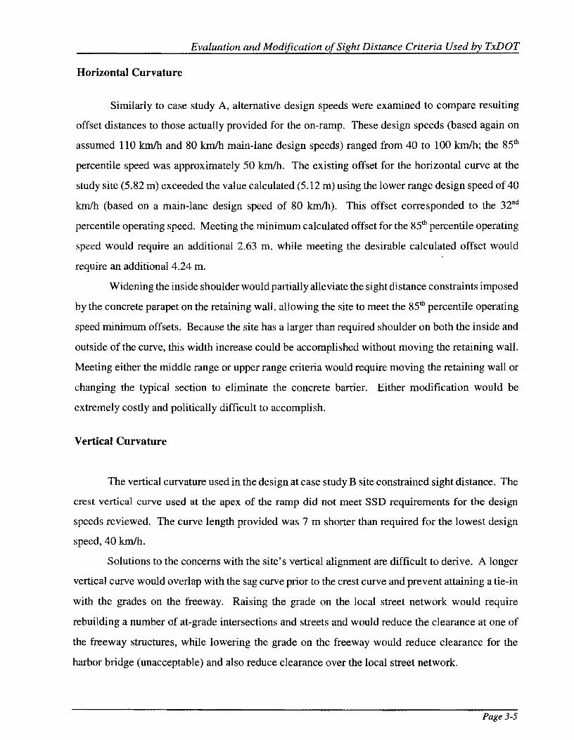
The second case study examined the on-ramp shown in Figures 3-2 and 3-3. The ramp
connects the local street network to a limited access freeway. The ramp design was complicated by
two factors: an historic structure limiting the availability of right-of-way and a harbor bridge that
provides clearance for large ocean-going ships. Both the horizontal and vertical curvature limited
the available sight distance on the ramp. The concrete parapet at the top of the retaining wall created
the small offset distance available on the inside of the horizontal curve on the ramp; the retaining
wall was necessary to prevent encroachment on the historic structure. The sharp vertical curvature
was dictated by the large grade difference and short horizontal distance between the surface street
network and the approach to the harbor bridge.
Page 3-3
Chapter 3 - Ramp Case Studies
Figure 3-2. Case Study B: Horizontal Curvature
Figure 3-3. Case Study B: Vertical Curvature
Page 3-4
Evaluation and Modification of Sight Distance Criteria Used by TxDOT
Horizontal Curvature
Similarly to case study A, alternative design speeds were examined to compare resulting
offset distances to those actually provided for the on-ramp. These design speeds (based again on
assumed 110 km/h and 80 km/h main-lane design speeds) ranged from 40 to 100 km/h; the 85ili
percentile speed was approximately 50 km/h. The existing offset for the horizontal curve at the
study site (5.82 m) exceeded the value calculated (5.12 m) using the lower range design speed of 40
km/h (based on a main-lane design speed of 80 km/h). This offset corresponded to the 32nd
percentile operating speed. Meeting the minimum calculated offset for the 85ili percentile operating
speed would require an additional 2.63 m, while meeting the desirable calculated offset would
require an additional 4.24 m.
Widening the inside shoulder would partially alleviate the sight distance constraints imposed
by the concrete parapet on the retaining wall, allowing the site to meet the 85ili percentile operating
speed minimum offsets. Because the site has a larger than required shoulder on both the inside and
outside of the curve, this width increase could be accomplished without moving the retaining wall.
Meeting either the middle range or upper range criteria would require moving the retaining wall or
changing the typical section to eliminate the concrete barrier. Either modification would be
extremely costly and politically difficult to accomplish.
Vertical Curvature
The vertical curvature used in the design at case study B site constrained sight distance. The
crest vertical curve used at the apex of the ramp did not meet SSD requirements for the design
speeds reviewed. The curve length provided was 7 m shorter than required for the lowest design
speed, 40 km/h.
Solutions to the concerns with the site's vertical alignment are difficult to derive. A longer
vertical curve would overlap with the sag curve prior to the crest curve and prevent attaining a tie-in
with the grades on the freeway. Raising the grade on the local street network would require
rebuilding a number of at-grade intersections and streets and would reduce the clearance at one of
the freeway structures, while lowering the grade on the freeway would reduce clearance for the
harbor bridge (unacceptable) and also reduce clearance over the local street network.
Page 3-5

Chapter 3 - Ramp Case Studies
CASESTUDYC
Case study C reviewed the design of an on-ramp connecting a frontage road to an exit ramp
from a freeway. The relatively unusual ramp location resulted from the stage construction of the
multiple freeways in the immediate vicinity, with the ramp providing needed access that has since
become redundant. The ramp, now permanently closed, provided problematic operation and an
unacceptably high accident rate while it was in operation.
Reviewing sight distance restrictions at the site, attention focused on the vertical alignment.
A crest and a sag vertical curve are present on the ramp which descends from the frontage road to
merge with the exit ramp (see Figures 3-4 and 3-5). An examination revealed that the design for
each curve met lower range ramp design speed desirable length criteria for both 80 and 110 km/h
main-lane design speeds. Comparisons regarding the 85tb percentile operating speed were not
available because of the ramp's closure.
Sight distance on the vertical curves present at the site appeared to be relatively good,
although it would have been desirable to compare operating speeds on the ramp with the design
speeds presented. Reasons for the poor performance of the ramp could be charged to several issues
(and have indeed been the subject of an extensive investigation). Modifications to the vertical
alignment of the ramp to improve available sight distance would be possible, although relatively
expensive due to the rolling terrain. The improvement might have improved the performance of the
facility, although the efficacy of such measures appears doubtful given the relatively good design
standard already in place.
CONCLUSIONS
The case studies revealed that appropriate design criteria are somewhat difficult to discern
in advance of the construction of a facility. Care must be taken to select appropriate design speeds
that yield acceptable designs. Design speeds that, although acceptable according to guidelines, only
accommodate a small percentage of drivers are problematic and inappropriate. Of course, the
difficulty lies in accurately predicting which design speeds are appropriate.
Page 3-6

Evaluation and Modification of Sight Distance Criteria Used by TxDOT
Figure 3-4. Case Study C: Crest Vertical Curve
Figure 3-5. Case Study C: Sag Vertical Curve
Page 3-7

Chapter 3 - Ramp Case Studies
Critiquing a design from the viewpoint of information not available to the designer at the
time the design was completed (i.e., using a spot speed study to calculate an 85th percentile speed)
is somewhat unrealistic and limited in application. It does, however, lead to the desire to have
additional guidance about the selection of ramp design speed in general. Reasonably accurate
predictions about operating speeds and design conditions on ramps would be helpful to the designer
as ramp curvature and sight distance requirements are selected for use in the design of an
interchange. However, ramp design speed lies outside the bounds of this study and is currently the
subject of other TxDOT research.
Clearly, the central issue remains that designers and planners must recognize at an early point
in the design of a facility that sight distance is of great importance in the operatiQn of that facility.
Both vertical and horizontal curvature must be examined with regard to their impacts on sight
distance. Although some modifications can be made to improve available sight distance at a given
location, frequently th0se modifications are ei'"her extremely expensfr:; or virtually impossib1e to
effect once the facility is in place.
Page 3-8

CHAPTER4
RECOMMENDATIONS FOR IMPLEMENTATION
This chapter provides proposed revisions to the Design Manuaz.<1> It is recommended that
these revisions be incorporated into the current rewrite of the Design Manual so that they become
effective when the Design Manual is republished. Existing TxDOT training courses may also be
used to inform designers of the proposed changes to the Design Manual.
The Design Manual communicates recommended design practices, procedures, and criteria
to highway designers and engineers. Although other references and design materials are frequently
and necessarily used by designers and engineers at TxDOT, this manual provides guidance regarding
geometric design.
The Design Manual has a number of references to sight distance in various sections, bet
substantive guidance is provided only with regard to stopping sight distance and passing sight
distance. Material related to intersection sight distance is scant, and decision sight distance is not
mentioned in the manual.
Stopping sight distance criteria are provided in the section on Basic Design Criteria. In this
section, a table presents minimum and desirable stopping sight distance values for design speeds
from 30 to 120 km/h. The minimum and desirable values reflect the range of stopping sight distance
values given in the 1994 Green Book. <2J The values in the Design Manual, however, are rounded up
to the nearest value of 10. In some instances, this results in a recommended value 9 m higher than
what is recommended in the Green Book.
Stopping sight distance is also addressed in the section on freeways in the discussion of sight
distance on ramps. In this section, the manual maintains that stopping sight distance is provided
along ramps from the terminal junctions along the freeway.
Intersection sight distance is mentioned very briefly in the discussions on intersections in
each of the following sections of the manual: Urban Streets, Multilane Rural Highways, and Two
Lane Rural Highways. In these sections, general statements are provided regarding intersection sight
distance and directing the reader to relevant sections of the manual.
Specific recommended changes to the text of the Design Manual follow. A brief discussion
of the reason for the changes is included with suggested wording for the recommended
Page4-l

Chapter 4 - Recommendations for Implementation
modifications. Figure and table numbers within the material quoted from the Design Manual refer
to the figures and tables as numbered within the Design Manual. Figures and tables are provided
only where proposed for modification (i.e., figures or tables extraneous to any proposed
modifications are not included).
BASIC DESIGN CRITERIA, DESIGN ELEMENTS, Sight Distance
In this section of the manual, sight distance is introduced with a brief rationale for its
importance. The only two types of sight distance previously mentioned, however, are stopping sight
distance and passing sight distance. Therefore, decision sight distance and intersection sight distance
are added to the discussion.
Of utmost importance" in highway design is the arrangement of geometric elements
so that there is adequate sight distance for safe and efficient traffic operation
assuming adequate light, clear atmospheric conditions, and drivers' visual acuity.
For design, two types of sight distance are considered. that for ove1taking vehicles,
and that reqttired for stopping. Passing sight distance is applicable only in the design
of two-lane nu al high \l\> a:y s and therefore is ptesented in Paragraph 4-502(D) four
types of sight distance are considered:
+ Stopping sight distance;
+ Decision sight distance;
+ Passing sight distance; and
+ Intersection sight distance.
BASIC DESIGN CRITERIA, DESIGN ELEMENTS, Sight Distance, Stopping Sight Distance
This section defines stopping sight distance and includes the criteria for its application. Table
4-1 [Design Manual Figure 4-3] provides distances to be used for various design speeds. Previously,
a very conservative hard conversion from English to metric units was used, providing up to an 11
percent increase in required sight distance. Because the values provided meet current design criteria
Page4-2

Evaluation and Modification of Sight Distance Criteria Used by TxDOT
and are already quite conservative, it is recommended that values are rounded to the nearest meter
rather than to the nearest ten meters.
Minimum stopping sight distance is the length of roadway required to enable a
vehicle traveling at or near design speed to safely stop before reaching an object in
its path. Minimum stopping sight distance values for various design speeds are
tabulated in Figure 4-3 [research report Table 4-1]. These values are based on
driver's eye height of 1,070 mm and object height of 150 mm as recommended by
AASHTO. After selection of design speed, stopping sight distance values become
a controlling element for several basic design features such as roadway alignment and
non-signalized intersection design. Greater than minimum stopping sight distances
should normally be used, and minimum values should be used only in select
instances where economic or other restrictive -_:onditions dictate (see Minimum
Standards).
Table 4-1. Recommended Changes to Design Manual Figure 4-3
Fie;ure 4-3. Stor>ping Sight Distance Values (Wet Pavements).
Stopping Sight Distance (m) Design Speed (km/h)
Minimum Desirable
30 30 30
40 5045 5045
50 6058 7063
60 8-675 9085
70 ±0095 He 111
80 tZ0 113 140
90 t4e 132 ±76169
100 t66157 Zte 205
110 180 250247
120 Zte203 290 286
Page4-3

Chapter 4 - Recommendations for Implementation
BASIC DESIGN CRITERIA, DESIGN ELEMENTS, Sight Distance, Decision Sight Distance
It is recommended that a section defining decision sight distance be provided to designers.
Criteria for its use should also be included.
Page4-4
Decision sight distance is the distance required for a driver to detect an unexpected
or otherwise difficult-to-perceive information source, recognize the source, select an
appropriate speed and path, and initiate and complete the required maneuver safely
and efficiently. Because decision sight distance gives drivers additional margin for
error and affords them sufficient length to maneuver their vehicles at the same or
reduced speed rather than to just stop, its values are substantially greater than
stopping sight distance. Table 4-2 [research report Figure 4-21 shows recommended
deci~ion sight distance valu~s for various avoidanc; maneuvers.
Examples of situations in which decision sight distance is preferred include the
following:
+ Interchange and intersection locations where unusual or unexpected maneuvers are
required (such as exit ramp gore areas and left-hand exits);
+ Changes in cross section such as toll plazas and lane drops: and
+ Areas of concentrated demand where there is apt to be "visual noise" whenever sources
of information compete. as those from roadway elements, traffic. traffic control devices,
and advertising signs.

Evaluation and Mod{fication of Sight Distance Criteria Used by TxDOT
Table 4-2. Recommended New Table
Table. Recommended Decision Sight Distance Values
Decision Sight Distance (m)
Design Avoidance Maneuver 1
Speed
(km/h) A B
50 75 160
60 95 205
70 125 250
80 155 300
90 185 360
100 225 415
110 265 455
120 305 505
l A: Stop on rural road.
B: Stop on urban road.
C: Speed/path/direction change on rural road.
D: Speed/path/direction change on suburban road.
E: Speed/path/direction change on urban road.
c
145
175
200
230
275
315
335
375
D
160
205
240
275
320
365
390
415
~
200
235
275
315
360
405
435
470
BASIC DESIGN CRITERIA, DESIGN ELEMENTS, Sight Distance, Intersection Sight
Distance
A section defining intersection sight distance and the rationale for its use is recommended
for inclusion in the manual. Full development of all of the AASHT0<2l models within the TxDOT
manual was judged to be unnecessary because no changes from AASHTO guidelines were
envisioned as necessary. Accordingly, designers are made aware of intersection sight distance and
referred to AASHTO' s A Policy on Geometric Design of Highways and Streets.
Page4-5

Page 4-6
Chapter 4 - Recommendations for Implementation
The operator of a vehicle approaching an intersection at grade should have an
unobstructed view of the entire intersection and an adequate view of the
intersecting highway to permit control of the vehicle to avoid a collision. When
designing an intersection, the following factors should be taken into
consideration:
+ Adequate sight distance should be provided along both highway approaches
and across comers.
+ Gradients of intersecting highways should be as flat as practical on sections
that are to be used for storage of stopped vehicles.
+ Combination of vertical and horizontal curvature should allow adequate sight
distance of the intersection.
+ Traffic lanes should be clearly visible at all times.
+ Lane markings and signs should be clearly visible and understandable from
a desired distance.
+ Intersections should be free from the sudden appearance of potential
conflicts.
For selecting appropriate intersection sight distance, refer to A Policy on
Geometric Design for Streets and Highwavs, AASHTO. Sight distance criteria
are provided for the following five types of intersection controls:
L No control, but allowing vehicles to adjust speed;
Yield control on minor roads;
3. Stop control on minor roads;
4. Signal control; and
5. Stopped vehicle turning left from major highway.
Evaluation and Modification of Sight Distance Criteria Used by TxDOT
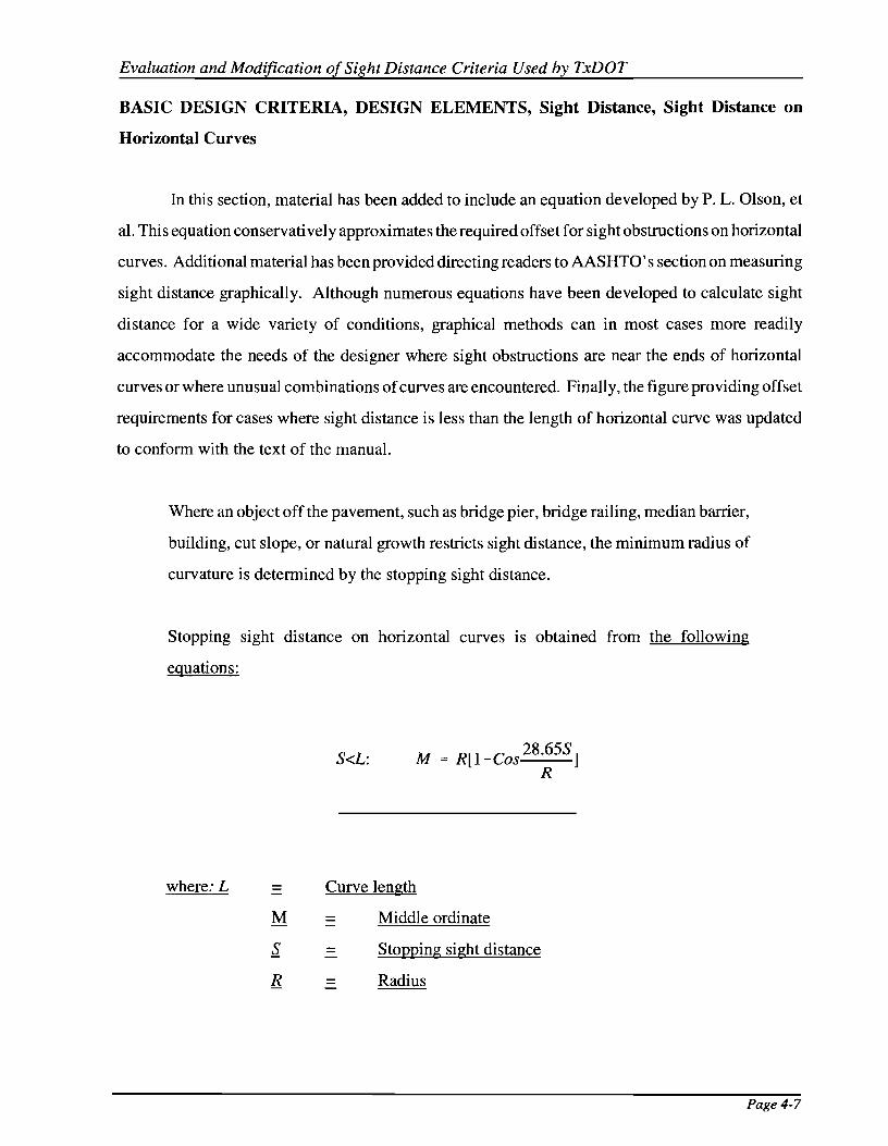
BASIC DESIGN CRITERIA, DESIGN ELEMENTS, Sight Distance, Sight Distance on
Horizontal Curves
In this section, material has been added to include an equation developed by P. L. Olson, et
al. This equation conservatively approximates the required offset for sight obstructions on horizontal
curves. Additional material has been provided directing readers to AASHTO' s section on measuring
sight distance graphically. Although numerous equations have been developed to calculate sight
distance for a wide variety of conditions, graphical methods can in most cases more readily
accommodate the needs of the designer where sight obstructions are near the ends of horizontal
curves or where unusual combinations of curves are encountered. Finally, the figure providing offset
requirements for cases where sight distance is less than the length of horizontal curve was updated
to conform with the text of the manual.
Where an object off the pavement, such as bridge pier, bridge railing, median barrier,
building, cut slope, or natural growth restricts sight distance, the minimum radius of
curvature is determined by the stopping sight distance.
Stopping sight distance on horizontal curves 1s obtained from the following
equations:
where: L
M
s. R
S<L: M = R[l -Cos 28·65S] R
Curve length
= -
= -
Middle ordinate
Stopping sight distance
Radius
Page4-7

Chapter 4 - Recommendations for Implementation
For S>L (from P. L. Olson et al., NCHRP Report 270, Parameters Affecting Stopping Sight
Distance, Transportation Research Board, Washington, DC, June 1984):
S>L: M= L(2S-L) 8R
where: L = Curve length -
M = Middle ordinate -
s = Stopping sight distance -
R = Radius -
Figure 4-12 [research report Figure 4-11 provides a graph illustrating the required
offset where stopping sight distance is less than the length of ct:rve (S<L).
Figure 4-12 [research report Figure 4-11 may be used in either case but may be overly
conservative for curves with small deflection angles. In cases where complex
geometries or discontinuous objects cause sight obstructions, graphical methods may
be useful in determining available sight distance and associated offset requirements.
It is assumed that the driver's eye is 1,070 mm above the center of the inside lane (inside with
respect to curve) and the object is 150 mm high. The line-of-sight is assumed to intercept the view
obstruction at the midpoint of the sight line and 600 mm above the center of the inside lane. The
clear distance is measured from the center of the inside lane to the obstruction.
To check horizontal sight distance on the inside of a curve graphically, sight lines
equal to the required sight distance on horizontal curves should be reviewed to ensure
that obstructions such as buildings, hedges, barrier railing, high ground, etc., do not
restrict sight below that required in either direction. See AASHTO's Chapter ill
section on measuring and recording sight distance on plans in Chapter 3 for further
information.
Page 4-8

Evaluation and Modification of Sight Distance Criteria Used by TxDOT
1,000
BOO
600 E -w 400 z c:( .... w 0 VI z 200 u.. 0 w z -_. 100 "' UI ... 80 z w u 60 .. GI:
VI 40 ::> Ci c:(
"' 20
0 I 2 3 5 6 7 8
MIDDLE ORDINATE, M, CENTERLINE INSIDE LANE TO SIGHT OBSTRUCTION (m)
11 , R [ (HOS 28. 655) J R
llH£RE
S • STOPPING SIGHT OtSTANCf
M • MIDOLE Of!OINATE R • RAOIUS
Figure 4-1. Revisions to Design Manual Figure 4-12. Stopping Sight Distance on Horizontal Curves
(Updated to conform with SSD values used in text)
9 10
Page 4-9

Chapter 4 - Recommendations for Implementation
NEW LOCATION AND RECONSTRUCTION (4R) DESIGN CRITERIA, URBAN
STREETS, Intersections
A brief mention of intersection sight distance is provided to direct the designer to the
appropriate section of the manual.
The number, design, and spacing of intersections influence the capacity, speed, and
safety on urban streets. Capacity analysis of signalized intersections is one of the
most important considerations in intersection design. Dimensional layout or
geometric design considerations are closely influenced by traffic volumes and
operational characteristics and the type of traffic control measures used.
Because of the space li'TI.itations and lower operating speeds on urban streets, curve
radii for turning movements are less than for rural highway intersections. Curb radii
of 4.5 m to 7.5 m permit passenger cars to negotiate right turns with little or no
encroachment on other lanes. Where heavy volumes of trucks or buses are present,
increased curb radii of 9 m to 15 m expedite turns to and from through lanes. Where
combination tractor-trailer units are anticipated in significant volume, reference
should be made to the material in section, MINIMUM DESIGNS FOR TRUCK
AND BUS TURNS.
In general, intersection design should be rather simple, and free of complicated channelization, to
minimize driver confusion. Sight distance is an important consideration even in the design of
signalized intersections since, during the low volume hours, flashing operation may be used. For
more information on sight distance as part of intersection design, see Intersection Sight Distance
Design, Chapter II.
Page4-10
Evaluation and Modification of Sight Distance Criteria Used by TxDOT
NEW LOCATION AND RECONSTRUCTION (4R) DESIGN CRITERIA, TWO-LANE
RURAL HIGHWAYS, Intersections
Text is added to this section recommending general design practices to be followed in the
vicinity of intersections, together with references to material on intersection sight distance.
The provision of adequate sight distance is of utmost importance in the design of
intersections along two-lane rural highways. At intersections, consideration should
be given to avoiding steep profile grades and locating intersections on or near a short
crest vertical curve or a sharp horizontal curve. These locations could result in poor
operations and/or inadequate sight distance at the intersection. Where necessary,
backslopes should be flattened and horizontal an,.d vertical curves lengthened to
provide additional sight distance. For more information on intersection sight
distance, see Intersection Sight Distance, Chapter II.
Desirably, the roadways should cross at approximately right angles. Where crossroad
skew is flatter than 60 degrees to the highway, the crossroad should be re-aligned to
provide for a near perpendicular crossing. The higher the functional classification,
the closer to right angle the crossroad intersection should be.
Section 4-710 provides information regarding the accommodation of various types
of truck class vehicles in intersection design. Further information on intersection
design may also be found in AASHTO's A Policy on Geometric Design of
Highways and Streets.
Page 4-11

Chapter 4 - Recommendations for Implementation
NEW LOCATION AND RECONSTRUCTION (4R) DESIGN CRITERIA, MULTILANE
RURAL HIGHWAYS, INTERSECTIONS
Reference is made to sight distance sections m appropriate locations. Further
recommendations are made for modifications at median openings to improve operations at those
points.
In the design of intersections, careful consideration should be given to the appearance
of the intersection from the driver's perspective. In this regard, design should be
rather simple to avoid driver confusion. In addition, adequate sight distance should
be provided throughout, especially in maneuver or conflict areas. See section on
Sight Distance in Chapter II for further information regarding sight distance.
Right-angle crossings are preferred to skewed crossings, and where skew angles
exceed 60 degrees, alignment modifications are generally necessary. Speed change
lanes may be provided in accordance with the previous discussion in the section on
Speed Change Lanes.
Section 4-710 provides information regarding the accommodation of various types
of truck class vehicles in intersection design. AASHTO's A Policy on Geometric
Design of Highways and Streets should be consulted for further information on
intersection design and intersection sight distance.
Intersections formed at bypass and existing route junctions should be designed so as
not to mislead drivers as typified in Figure 4-35.
For intersections with a narrow, depressed median section, it may be necessary to
have superelevation across the entire cross section to provide for safer operation at
the median openings.
For more information on intersection design, see Intersection Design, Chapter II.
Page4-12

Evaluation and Modification of Sight Distance Criteria Used by TxDOT
NEW LOCATION AND RECONSTRUCTION (4R) DESIGN CRITERIA, FREEWAYS
Modified text is provided to allow reversing the inside and outside shoulder width
recommendations for bridges if sight distance requirements may be met in this manner. Providing
a larger inside shoulder will in some cases provide improved sight distance without moving the
structures. The combination of the inside and outside shoulder widths would still permit passing a
stalled vehicle. Table 4-3 contains the recommended revisions to the Design Manual's Figure 4-51.
Table 4-3. Revisions to Figure 4-51 in the Design Manual
Figure 4-51. Roadway and Structure Widths for Controlled Access Facilities.
Outside Traffic Type of Inside Shoulder Shoulder Lanes Structure
Roadway Width (m) Width1 (m) (m) Width (rn)
Mainlanes:
4-Lane Divided 1.2 3.0 7.2 11.4 Min.
6-Lane Divided 3.01 3.0 10.8 16.8 Min.2
8 Lanes or More 3.0 3.0 14.43 20.4 Min.3
1-Lane Direct 0.6 Rdwy. See 2.4 4.2 7.8 Min.
Conn.2 1.2 Str. Note4
2-Lane Direct Conn. 0.6Rdwy. See 2.4 7.2 10.8 Min.
1.2 Str. Note4
Rampsl I 0.6Rdwy. See Min. Des. Min. Des.
1.2 Str. Note4 1.8 2.45 4.2 7.2 7.85
Median Width Urban 7.26 -- --
(usual)
Rural 14.4
Minimum 3.0 minside shoulders are usually provided on urban freeways with flush medians and six
or more lanes. For urban freeway rehabilitation and expansion, the provision of wide inside
shoulders may not be feasible. Under these circumstances documentation for narrower shoulders
should be submitted and a design exception requested. Six-lane freeways with depressed median
may include 1.2 m shoulders with 15.0 m minimum structure width.
Page4-13
4
5
6
Chapter 4 - Recommendations for Implementation
For auxiliary (speed change) lanes, see Main Lanes, Shoulders for outside shoulder width.
For more than eight lanes, add 3.6 m width per lane.
Minimum inside shoulder width is 0.6 m on uncurbed roadway sections and 1.2 m on bridges and
curbed roadways. All longitudinal traffic barriers, including bridge rail, wall, and guard fence,
should be located a minimum of 1.2 m from the travel lane edge.
Desirable values should be used where there are sufficient combination type vehicles to govern
design. Where ramp ADT includes greater than 10 percent trucks, desirable values are appropriate
for use.
Applicable to urban freeways with flush medians and six or more mainlanes.
If sight distance restrictions are present due to horizontal curvature, the shoulder width on the inside
of the curve may be increased and the shoulder width on the outside of the curve decreased to 0.6
m (Rdwy) or 1.2 m (Str).
NEW LOCATION AND RECONSTRUCTION (4R) DESIG~~ CRITERIA, FREE~N A YS,
Sight Distance
Text is provided to indicate the need for increased sight distance on a freeway prior to an exit
ramp. Decision sight distance or, alternatively, a 25 percent increase in stopping sight distance, is
recommended to the designer for this situation.
On all ramps and direct connections, the combination of grade, vertical curves,
alignments, and clearance of lateral and corner obstructions to vision shall be such
as to provide sight distance along such ramps and connections from terminal
junctions along the freeway, consistent with the probable speeds of vehicle operation.
Figure 4-55 shows recommended minimum and desirable stopping sight distances
for ramps and direct connections.
The sight distance on a freeway preceding the approach nose of an exit ramp should
exceed the minimum stopping sight distance for the freeway design speed, preferably
by 25 percent or more. Decision sight distance, as discussed in Chapter II, Decision
Sight Distance, is a desirable goal.
Page4-14

Evaluation and Modification of Sight Distance Criteria Used by TxDOT
LONGITUDINAL BARRIERS, CONCRETE BARRIERS. LOCATION
Text is provided to indicate to the designer that the provision of concrete barriers may impede
sight distance on horizontal curves.
On controlled access highways, concrete barriers will generally be provided in
medians of 9.0 m or less. On non-controlled access highways, concrete barriers may
be used on medians of 9.0 m or less; however, care should be exercised in their use
in order to avoid the creation of an obstacle or restriction in sight distance at median
openings or on horizontal curves. Generally, the use of concrete barriers on
non-controlled access facilities should be restricted to areas with potential safety
concerns such as railroad separations or through areas where median constriction
occurs.
Page4-15


REFERENCES
1. Highway Design Division Operations and Procedures Manual (Part IV) (INTERIM METRIC VERSION). Texas Department of Transportation, 1994.
2. A Policy on Geometric Design of Highways and Streets. American Association of State Highway and Transportation Officials, Washington, D.C., 1994.
3. Fambro, D. B., K. Fitzpatrick, and R. J. Koppa. Determination of Stopping Sight Distance and unpublished Appendix A. NCHRP Report 400, Transportation Research Board, National Research Council, Washington, D.C., 1997.
4. Hauer, E. "A Case for Science-Based Road Safety Design and Management." Highway Safety at the Crossroads Conference Proceedings. American Society of Civil Engineers, NY, 1988, pp. 241-267.
5. Gordon, D. A. Perceptual Bases of Vehicular Guidance. Public Roads. Vol. 34, No. 3, August 1966, pp. 53-'.7.
6. Leisch, J.E. Dynamic Design for Safety. An Institute of Traffic Engineers Seminar, 1975.
7. Alexander, G. J., and H. Lunenfeld. Positive Guidance in Traffic Control. Federal Highway Administration, U.S. Department of Transportation, April 1975.
8. McGee, H. W., W. Moore, B. G. Knapp, and J. H. Sanders. Decision Sight Distance for Highway Design and Traffic Control Requirements. Report FHWA-RD-78-78, Federal Highway Administration, U.S. Department of Transportation, 1978.
9. Baker, J. S., and W. R. Stebbins. Directory of Highway Traffic. Traffic Institute, Northwestern University, Evanston, IL, 1960.
10. Leisch, J.E. Communicative Aspects in Highway Design. Presented at 8th Summer Meeting, Transportation Research Board, Ann Arbor, Ml, August 1975.
11. Pfefer, R. C. New Safety and Service Guides for Sight Distances. Transportation Engineering Journal, ASCE, November 1976, pp. 683-697.
12. A Policy on Geometric Design of Highways and Streets. American Association of State Highway and Transportation Officials, Washington, D.C., 1984.
13. A Policy on Geometric Design of Highways and Streets. American Association of State Highway and Transportation Officials, Washington, D.C., 1990.
14. A Policy on Sight Distance for Highways. American Association of State Highway Officials, Washington, D.C., 1940.
Page R-1

Evaluation and Modification of Sight Distance Criteria Used by TxDOT
15. Pinnell, C. Driver Requirements in Freeway Entrance Ramp Design. Traffic Engineering, December 1960.
16. Bhise, V. D. Visual Search by Drivers in Freeway Merging: Implications for Vehicle Design. Proceedings of the Seventeenth Annual Meeting of the Human Factors Society, Santa Monica, CA, October 1973, pp. 152-161.
17. Harwood, D. W., J. M. Mason, R. E. Brydia, M. T. Pietrucha, and G. L. Gittings.
Page R-2
Intersection Sight Distance. NCHRP Report 383, Transportation Research Board, Washington, D.C., 1996.