Embed Size (px)
Citation preview

1
In accordance with Article 3 of the Treaty on the Eurasian Economic Commission of 18 November 2011,
the Council of the Eurasian Economic Commission decided to:
1. Adopt the attached technical regulations of the Customs Union "On the safety equipment of high
pressure" (TR TC 032/2013).
2. Establish that the technical regulations of the Customs Union "On the safety equipment of high pressure"
(TR TC 032/2013) comes into force on February 1, 2014
3. This Decision shall enter into force after 30 days from the date of its official publication.
Members of the Council of the Eurasian Economic Commission:
From the Republic of Belarus Of the Republic of Kazakhstan From the Russian Federation
S. Roumas K.Kelimbetov Shuvalov
ACCEPTED Council Decision Eurasian Economic Commission
TECHNICAL REGULATIONS Customs Union "On the safety equipment of high pressure"
(TR TC 032/2013)
This technical regulation is designed in accordance with the Agreement on common principles and rules of
technical regulation in the Republic of Belarus, Kazakhstan and the Russian Federation of November 18, 2010.
This technical regulation establishes the customs territory of the Customs Union uniform mandator y for
application and enforcement of safety requirements for equipment operating under positive pressure, first put
into circulation and intended for use in the customs territory of the Customs Union (hereinafter - equipment) to
ensure the free movement of equipment.
If in respect of other equipment adopted technical regulations of the Customs Union, establish requirements
for it, such equipment must comply with the requirements of the technical regulations of the Customs Union.
I. Scope 1. This technical regulation establishes safety requirements for equipment in the development (design),
production (manufacturing), as well as requirements for labeling equipment in order to protect human life and
health, property, prevention of actions misleading consumers.
2. This technical regulation applies to the following types of equipment:
a) vessels for gases, liquefied gases, dissolved under pressure, vapors and used for working environments
group 1 and having:
- a maximum allowable operating pressure in excess of 0.05 MPa, a capacity greater than 0,001 m 3 and the
product of the maximum allowable working pressure on the value of capacity, constituting more than 0.0025

2
MPa · m 3 ,
- maximum allowable working pressure of over 20 MPa, capacity more than 0.0001 m 3 to 0.001
m 3 inclusive.
Categories receptacles for gases and used working environments for group 1 are shown in Table 1 of Annex
1 to the number of technical regulations;
b) Receptacles for gases, liquefied gases, dissolved under pressure, vapors and used to working fluid in
group 2 and having:
a maximum allowable operating pressure in excess of 0.05 MPa, a capacity greater than 0,001 m 3 and the
product of the maximum allowable working pressure on the value of the capacity of well over 0,005 MPa ·
m 3 ,
maximum allowable working pressure of more than 100 MPa, capacity more than 0.0001 m 3 to 0.001
m 3 inclusive.
Categories receptacles for gases and used for production environments 2 groups are shown in Table 2 of
Annex 1 to the number of technical regulations;
c) intended to contain liquids used for working fluid in group 1 and having:
a maximum allowable operating pressure is above 0.05 MPa capacity of more than 0,001 m 3 and the
product of the maximum allowable working pressure on the value of the capacity of well over 0.02 MPa · m 3 ,
maximum allowable working pressure greater than 50 MPa, capacity over 0.0001 m 3 to 0.001
m 3 inclusive.
Categories receptacles for liquids and used for working environments in group 1 are shown in Table 3 of
Annex 1 to the number of technical regulations;
g) intended to contain liquids used for working fluid in group 2 and having:
a maximum allowable operating pressure in excess of 1 MPa capacity of more than 0.01 m 3 and the product
of the maximum allowable working pressure on the value of capacity, is more than 1 MPa · m 3 ,
maximum allowable working pressure of more than 100 MPa, capacity over 0.0001 m 3 to 0.01
m 3 inclusive.
Categories of vessels designed for liquids and used for working fluid in group 2 are shown in Table 4 of
Appendix 1 to the number of technical regulations;
d) boilers having a capacity of more than 0,002 m 3 , intended to produce hot water at a temperature above
110 0 C, or steam , the excess pressure is above 0.05 MPa, and the vessels of
the fired, having a capacity of more than 0,002 m 3 .
Categories of steam, hot water boilers and fired vessels are shown in Table 5 of Annex 1 to the number of
technical regulations;
e) piping having a maximum allowable operating pressure above 0.05 MPa, a nominal diameter of 25 mm
for gases and vapors are used for working fluid in group 1.
Categories pipelines intended for gases and vapors are used for working fluid in group 1 are shown in Table

3
6 application number 1 to this technical regulation;
g) pipes having a maximum allowable operating pressure in excess of 0.05 MPa, nominal diametrbolee 32
mm and the product of the maximum allowable working pressure on the nominal diameter over 100 MPa · mm
for gases and vapors used for working fluid in group 2.
Categories pipelines intended for gases and vapors and used for production environments 2 groups are
shown in Table 7 of Annex 1 to the number of technical regulations;
h) pipes having a maximum allowable operating pressure in excess of 0.05 MPa, nominal diameter of more
than 25 the product of the MMI maximum allowable operating pressure value of the nominal diameter of more
than 200 MPa · mm, intended for liquids and used for the working fluid in group 1.
Categories pipelines intended for liquids and used for the working fluid in group 1 are shown in Table 8
application number 1 to this technical regulation;
and) pipes having a maximum allowable operating pressure in excess of 1 MPa, a nominal diameter of 200
mm and the product of the maximum allowable working pressure on the nominal diameter of more than 500
MPa · mm, intended for liquids and used for working fluid in group 2.
Categories pipelines designed for liquids and used for production environments 2 groups are shown in
Table 9 of the annex number 1 to this technical regulation;
k) items of equipment (assembly units) and accessories to it, pressure-resistant,
l) valves having a nominal diameter of 25 mm (for equipment with fluid group 1), fittings, having a
nominal diameter of 32 mm (for equipment used for gas with fluid group 2), fitti ngs, having a nominal diameter
of 200 mm (for pipelines designed for liquids and used for working environments group 2);
m) showing and safety devices;
n) hyperbaric chambers (except single medical);
o) devices and safety equipment.
3. This technical regulation does not apply to the following products:
a) pipelines, local distribution and infield pipelines designed to transport gas, oil and other products, with
the exception of equipment used on the pressure regulating stat ions or compression stations;
b) timing network and network gas consumption,
c) equipment specially designed for use in nuclear power equipment, working with radioactive
environment;
g) vessels working under pressure created by the explosion inside them, in accordance with the process or
during combustion mode of self-propagating high-temperature synthesis;
d ) equipment specially designed for use in marine and river vessels and other floating objects and
underwater applications,
e) braking equipment, railway rolling stock, vehicles and other vehicles;
g) vessels specifically designed for use
on aircraft and other flying machines ,

4
h) equipment for defense purposes;
s) of the equipment shall not constitute separate vessels (hull pumps or turbines, steam engine cylinders,
hydraulic, internal combustion engines, air compressors and machines);
k) Single medical hyperbaric chambers;
l) equipment with a spray bottle ,
m) shell of high-voltage electrical equipment (switchgear, control gear, transformers and rotating electrical
machines),
n) and the shell casing of elements of the transmission of electric energy (power cables and communication
cables) operating pressurized;
o) equipment manufactured (produced) of non-metallic flexible (elastic) shell,
n) silencers or exhaust gas suction;
p) vessel or siphons for carbonated beverages.
II. Basic Concepts 4. For the purposes of this technical regulation of the concepts used are as follows:
"Tank" - a vessel having 1 or 2 neck to install valves, flanges or fittings designed for transportation, storage
and use of compressed, liquefied or dissolved gases;
"pressure chamber" - a vessel , which creates a low and (or) high blood pressure, which is equipped with
instruments and equipment, and in which people can be accommodated,
"barrel" - a vessel of cylindrical or other shape, which may be rolled from one place to another and put on
the ends without additional supports and which is designed for the transportation and storage of liquid and other
substances;
"Commissioning" - documented event, fixing equipment availability for use (use)
"capacity" - the volume of the inner cavity of the equipment determined by the figures given nominal size,
"a group of workers media "- a set of working environments, subdivided into:
group 1, which includes working environment consisting of a flammable, oxidizing, flammable, explosive,
toxic and highly toxic gases, vapors and liquids in the single -phase state, as well as mixtures thereof;
Group 2 includes all other Fluids which are not assigned to the group 1,
"internal pressure", "external pressure" - the overpressure acting on the inner or outer wall surface of the
equipment;
"Pressure test" - a positive pressure which is produced when the test equipment on the strength and
density;
"working pressure" - the maximum overpressure caused the normal flow of the workflow
"pressure allowed" - the maximum operating pressure for the equipment (element), set on the basis of
conformity assessment and (or) control based on strength;
"pressure rated" - pressure for which the calculation is performed on the strength equipment
5
"pressure conditional" - design pressure at 20 0 C, used in the calculation of the strength of standard vessels
(components, parts, fittings);
"nominal diameter", "conditional pass" - numeric designation size value equal to the rounded internal
diameter of which is indicated for all hardware components other than the components mentioned at the outer
diameter or size of the thread. Nominal diameter and nominal inside diameter in millimeters without indication
of dimension,
"identification equipment" - equipment classification procedure for the application of these technical
regulations and the establishment of compliance of equipment accompanying technical documentation,
"manufacturer" - a legal entity or natural person registered as an individual entrepreneur, which carry out
on its behalf manufacture or production and sale of equipment and are responsible for compliance with safety
requirements of this technical regulation;
"HRSG" - a device in which the source of heat used flammable gases or other process streams;
"Boiler Power Technological" - steam or boiler including soda recovery), in which the processing furnace
process materials;
"electrode boiler" - steam or hot water boiler, which uses the heat generated by the flow of electric current
through water;
"boiler with heating" - steam or hot water boiler , which uses the heat generated by the heating elements;
"fired boiler" - a device designed to heat water under pressure greater than atmospheric and used as a
coolant is that device
"steam boiler" - a device designed to produce steam at a pressure above atmospheric, this device is used,
"safety case" - a document containing the risk analysis, as well as information f rom the design, operation,
technical documentation about the minimum required security measures to accompany the equipment at all
stages of the life cycle and is supplemented by information on the results of the risk assessment operation stage
after a major overhaul;
"limit state equipment" - equipment condition in which its continued operation is unacceptable;
"intended use" - the use of equipment in accordance with its purpose and technical characteristics indicated
in the technical documentation of the manufacturer;
"serial production "- the type of production, characterized by the manufacture of similar products on the
model design decisions and (or) the use of standard processes associated with unchanging types of equipment,
including assembly operations, for manufacturing (production) recurring items of equipment regardless of the
types of further assembly ,
"Repair" - restoration of damaged, worn or dilapidated for any reason vascular elements with bringing them
to a healthy state,
"resource assigned" - the total time above which the operation of the equipment must be stopped regardless
of its technical condition,
"vessel "hermetically-closed receptacle (permanently installed or mobile), intended for conducting

6
chemical, thermal and other processes, as well as for storage and transport of gaseous, liquid and other
substances;
"lifetime appointment" - calendar duration of the operation of the equipment, above which operation should
be stopped, regardless of its technical condition,
"the life of the settlement" - the life of a calendar year, set in the design and calculated from the date of
commissioning of the equipment,
"medium temperature" - the minimum (maximum) temperature of the medium at normal flow of
technological process,
"the estimated wall temperature" - the temperature at which determined by the physical and mechanical
properties, the allowable stress of the material and the calculation is carried out on the strength of pieces of
equipment;
"wall temperature permissible" - the maximum (minimum) wall temperature at which permitted operation
of the equipment;
"authorized manufacturer face "- registered in accordance with the laws of the State - a member of the
Customs Union and the Common Economic prostranstvana its territory a legal entity or natural person as an
individual entrepreneur, operating functions of the foreign manufacturer under a contract with him in terms of
ensuring compliance with the equipment requirements hereof and of the responsibility for non-hardware
requirements hereof;
"safety device" - a device designed to protect vessels, boilers, piping from destruction in excess of
permissible values of the pressure or temperature;
"cycle of life" - the time period since the release of the equipment manufacturer to its disposal;
"tank" - a mobile vessel permanently mounted on the frame rail platform on the vehicle chassis (trailer),
including trucks, or other vehicles designed for the transport and storage of gaseous, liquid and other
substances;
"maintenance of equipment" - the stage of the life cycle since the commissioning of the equipment prior to
its disposal;
"piece of equipment" - the subassembly of equipment designed to perform one of its basic functions.
III. Market circulation 5. Equipment is available in market circulation at present under its technical regulations and other technical
regulations of the Customs Union, which apply to the equipment, and provided that it has passed the assessment
(confirmation) of compliance in accordance with Section VI of these technical regulations and other technical
regulations of the Customs Union, the effect of which it is subject.
6. Equipment, compliance with which the requirements hereof not checked, no one has to be labeled with a
mark of products on the market of the Member States of the Customs Union and not allowed to be released into
circulation.
7
IV. Security equipment in the development (design), manufacturing 7. Equipment must be designed (designed) and manufactured (made) so that when used a s directed,
operation and maintenance ensures that it meets safety requirements.
8. In order to determine the risks to equipment must be factored represent the following major hazards:
a) the presence of unprotected moving parts
b) vibration,
c) the highly explosive elements;
g) invalid parameter deviations in design, assembly units and security devices that may affect safety ,
d) fire, emergencies of natural and manmade;
e) overheating;
g) the excess pressure (working pressure does not exceed the permitted);
h) damage caused by the deposition of impurities working environment on the internal surfaces of
equipment components,
and) corrosion or other types of surface wear items of equipment;
k) failure of safety devices and safety systems;
l) Termination of auxiliary equipment;
m) flame failure in the furnace combustion chamber;
n) the disappearance of voltage on all test instruments, devices, remote and automatic control,
on ) reduction of the motive liquid below the minimum level;
n) improving the working environment above the maximum permissible level;
p) decrease coolant flow through the boiler below the minimum value;
c) reducing the pressure in the coolant path boiler below the minimum level of significance;
t) increase the coolant temperature at the outlet of the equipment to the limit specified by the manufacturer,
y) the failure of the level gauges working environment of direct action.
9. For the identified hazards in the design risk assessment calculations, experimental, or by experts
according to the operation of similar types of equipment.
10. Depending on the capacity of the equipment or the nominal diameter and maximum allowable working
pressure is classified by categories (1st, 2nd, 3rd and 4th) in accordance with Annex 1 to this number the
technical regulations.
11. Safety equipment is ensured by compliance with the development (design), manufacturing (production)
of the safety requirements set out in this section and Appendix number 2 to this technical regulation.
12. In manufacturing (production) of equipment and safety devices provided by the manufacturer of their
compliance with the parameters and characteristics set design documentation and the requirements hereof.
13. The manufacturer is testing the equipment in the project design.

8
14. Deviations from project documentation in the production (manufacturing) equipment coordi nated with
the developer (designer).
15. Equipment must be safe for the lifetime when the consumer merpo ensure its safety established in the
technical documentation.
16. Technical documentation accompanying the equipment includes:
a) a passport equipment
b) a copy of the safety case;
c) general drawing;
g) passport safety devices (if any, in accordance with the project documentation);
d) payment capacity of the relief devices (if any, in accordance with the project documentation);
e) Calculation of strength equipment;
g) management (user) manuals;
h) the drawings, diagrams, calculations, and other documentation in accordance with the supply (contract).
17. Certificate of equipment is the main document to identify the equipment.
A passport is mandatory for equipment handling equipment in the customs territory of the Customs Union
at all stages of the life cycle of the equipment.
Passport issued equipment manufacturer.
Passport stamp affixed equipment manufacturer and the date of its registration.
18. Depending on the type of equipment certificate of equipment shall contain information in accordance
with paragraphs 19 - 23 of these technical regulations.
19. Passport pipeline includes the following information:
a) the name and address of the owner;
b) appointment;
c) the date of manufacture (production),
d) the work environment;
d) the operating parameters of the working environment: pressure, MPa (kgf / cm 2 ) temperature, 0 C,
e) the life expectancy;
g) design life;
h) the estimated number of starts,
and) diagrams, drawings, certificates and other documents for manufacturing (production) and th e
installation of the pipeline.
20. Passport boiler includes the following information (the amount of information forms the manufacturer
depending on boiler type):
a) General information:
name and address of the manufacturer,
date of manufacture (production),

9
type (model)
name and designation,
serial number,
estimated lifetime ;
design life of the boiler and main parts;
estimated number of starts,
the geometric dimensions of the boiler and its components;
b) specifications and parameters:
the estimated fuel and its calorific value, MJ / kg (kcal / kg),
fuel consumption, m 3 / h (t / h),
the type and characteristics of the furnace system (burners),
calculated, business, test pressure, MPa (kgf / cm 2 ),
the maximum allowable flow resistance boiler at nominal performance, MPa (kgf / cm 2 ),
the minimum allowable pressure rated temperature, MPa (kgf / cm 2 )
the nominal temperature of the steam leaving the boiler, 0 C,
the estimated temperature of the superheated steam (liquid), 0 C,
the nominal temperature of the liquid at the boiler inlet, 0 C;
nominal and maximum fluid temperature exiting the boiler, 0 C;
nominal, minimum and maximum allowable steam, t / h,
nominal, minimum and maximum output in kW;
surface heating boiler and main parts, m 2 ;
capacity, m 3 ,
the minimum and maximum allowable flow rate , m 3 / h
) details about the safety devices (including the type, quantity, location of installation, cross -sectional area,
nominal diameter, flow coefficient in vapor or liquid, the value (range) of the opening),
d) information about liquid level indicator (water) (including a pointer type, quantity, location of
installation);
d) information on the main fixture (including the number, nominal diameter, nominal pressure, operating
parameters, body material, installation location)
e) information on the basic equipment for measurement, control, signaling, control and automatic
protection (including the number, type (name));
g) information about the pumps (including the type, number, operating parameters, drive);
h) information about the basic elements of the boiler manufactured (made) from sheet steel (including the
number, size, material, welding and heat treatment);
i) information on the elements of the boiler manufactured (made) from the pipes (including the number,
size, material, welding and heat treatment) ,

10
k) information on fittings, lids, bottoms, reducers, flanges (including the number, size, material);
l) information on the coolant (including the name, the maximum allowable operating temperature, ignition
temperature in an open space, the solidification temperature, boiling temperature change (curve) the boiling
temperature depending on the pressure, other data affecting the safe operation),
m) drawings, diagrams, drawings boiler and its essential elements and other documents (summary sheet
factory changes, pick list, indicating the specification the main dimensions of assembly units, etc.);
n) other information to ensure safe operation of the boiler.
21. Passport vessel includes the following information:
a) General information:
name and address of the manufacturer
date of manufacture (production);
serial number;
expected lifetime;
b) information on the technical characteristics and parameters:
business, design, test pressure, MPa (kgf / cm 2 )
working fluid temperature, 0 C,
the estimated wall temperature, 0 C,
the minimum allowable negative wall temperature, 0 C,
the name of the working environment;
group working environment;
increase to compensate for corrosion (erosion), mm;
capacity, m 3 ,
the mass of the empty vessel, kg
maximum weight of filled environment kg
c) information about the main parts (including the number, size, material, welding (soldering))
g) information on the fittings, flanges, caps, fasteners ( including the number, size, material);
d) information on the safety devices, the main fixture, measuring devices, security devices (including the
number, nominal diameter, design pressure, body material, installation location)
e) drawings, diagrams, drawings and other documents of the vessel (combined leaf plant changes, a pick list,
the specification with principal dimensions of assembly units, etc.)
g) other information to ensure safe operation of the vessel.
22. Passport balloon includes the following information:
a) General information:
name and address of the manufacturer
date of manufacture (production)
designation of the container;

11
Wednesday, which is designed for the balloon
serial number,
b) Information on the technical characteristics and parameters:
working pressure, MPa (kgf / cm 2 ),
test pressure, MPa (kgf / cm 2 ),
the basic dimensions balloon, balloon drawing,
capacity, l,
weight, kg;
neck thread;
sealing manholes,
operating temperature range, 0 C,
the maximum number of refills ,
the design life from date of manufacture (production) years;
c) requirements for transport and storage container;
d) requirements for installation of the container;
d) requirements for the operation of the container;
e) other information to ensure safe operation of the cylinder.
23. Passport valve includes the following information:
a) General information:
name and address of the manufacturer
date of manufacture (production)
the name, designation and identification (serial) number;
appointment reinforcement;
information on conformity assessment,
b) information about the technical parameters:
diameter Nominal (DN);
nominal pressure (PN) or working pressure (Pp), MPa (kgf / cm 2 )
working environment;
fluid temperature, 0 C;
obturator tightness;
climatic performance and environmental parameters,
the type of connection to the pipeline;
hydraulic characteristics (coefficient of resistance, or notional bandwidth, or flow coefficient),
resistance to external influences (if you must specify this information),
weight in kilograms;
reliability indices;

12
indicators security
type and its main technical characteristics;
c) gives information on the major parts;
g) other information to ensure safe operation of the boiler.
24. Manufacturer may supplement the information specified in paragraphs 19 - 23 of these technical
regulations, information reflecting the specific design features of the equipment.
25. Justification security equipment prepares to stage of development (design) of the equipment.
The justification given security risk analysis for the equipment, as well as the minimum necessary safety
measures.
Original of the safety equipment is kept by the developer (designer), and a copy - the manufacturer of the
equipment and organization, operating equipment.
26. Equipment manufacturer shall provide guidance equipment (instruction) manual.
Guide (user) manual prepared on stage of development (design) of the equipment.
27. Manual (user) manual includes:
a) information on the design, principle of operation, characteristics (properties) equipment
b) instructions for installation or assembly, setup or adjustment, maintenance and repair of equipment;
c) guidance on the use of equipment and safety measures that must be taken when using the equipment
(including commissioning, proper use and maintenance of all types of repair, periodic diagnostics, testing,
transportation, packaging, preservation and storage conditions);
g) assigned readings (the appointed time storage specified lifetime and (or) the assigned resource)
depending on the design features.
After designated indicators (designated retention period specified lifetime and (or) the assigned resource)
specified in the user manual (instruction) manual, stops operation of the equipment and to decide on the
direction of its repair, or disposal of, or the testing and the establishment of new designated indicators (assigned
resource shelf life, life);
d) a list of critical failures, possible false operations, which lead to an incident or accident ,
e) personnel actions in the event of an incident, accident or critical failure;
g) limit state criteria;
h) instructions for decommissioning and disposal;
i) information on the qualifications of the service staff;
k) the name, location and contact information of the manufacturer (manufacturer's authorized person), the
importer.
28. Manual (user) manual prepared in Russian and with the appropriate requirements in the legislation of
the Member States of the Customs Union and the Common Economic Space (hereinafter - the Member States)
in the official languages of the Member States.
Manual (user) manual is issued on paper when this may be accompanied by a set of operational documents

13
on electronic media. Non-domestic equipment to the kit manufacturer's choice of destination may be
accompanied by guide (manual) operating only on an electronic medium.
29. Equipment applied markirovkav as clearly and indelibly marked, containing the following information:
a) name and (or) type designation, make, model, equipment,
b) parameters and characteristics affecting safety;
c) name of the material from which made (produced) equipment (items);
d) trademark of the manufacturer (if available)
d) the serial number;
e) The date of manufacture (production).
30. Location of that marking is determined by the design organization and is specified in the user manual
(instruction) manual.
If the information specified in paragraph 29 of this technical regulation can not be applied directly to the
equipment, they can only be specified in the attached to this equipment manual (instructions) for operation.
31. Equipment designed for the transport of liquefied petroleum gas (cylinders and tankers), applied
distinctive coloring and identification information in accordance with the requirements of the application
number 3 to this technical regulation. When coating (plating) of equipment corrosion-resistant and
heat-insulating materials paint the entire length can not be made .
32. Elements and completing equipment labeled in accordance with the contract for the supply of
(contract). Labelling should provide their identification.
33. Technical documentation on the equipment stored at the manufacturer (person designa ted by the
manufacturer) for the design life from the date of removal from the production of this equipment or the
termination of its production.
34. Terms of the equipment established by the legislation of the Member States.
V. Ensuring compliance with safety requirements 35. Match equipment requirements hereof provided by direct implementation of these requirements or by
the requirements of the standards included in the list of standards as a result of which, on a voluntary basis,
compliance with these technical regulations.
36. Research methods (tests) and measurements of equipment set standards included in the list of standards
containing the rules and methods of researches (tests) and measurements, including the rules of sampling
required for the application and enforcement of the requirements of this Technical Regulation and
implementation of assessment (confirmation) of compliance equipment.
VI. Rating (s) matching equipment 37. Equipment manufactured in circulation in the customs territory of the Customs Union, subject to
evaluation (confirmation) of compliance requirements hereof.

14
38. Grade (s) that equipment requirements hereof is held in the form of state control (supervision) in the
form of conformity.
39. State control (supervision) over observance of this technical regulation is carried out in accordance with
the laws of the Member States.
40. Demonstration of compliance with the equipment requirements hereof (hereinafter - the conformity
assessment) is done by:
a) certification by an accredited certification body (assessment (confirmation)) included in the Unified
Register of certification bodies and testing laboratories (centers) of the Customs Union (hereinafter - the body
certification),
b) declaration of conformity based on their own evidence, and (or) evidence obtained with the certification
body or an accredited testing laboratory (center) included in the Unified Register of certification bodies and
testing laboratories (centers) of the Customs Union (hereinafter - accredited testing laboratory).
41. Demonstration of compliance is carried out according to the schemes of certification and declarations
established by the present technical regulation.
42. Declaration of conformity of the equipment requirements hereof is held by the applicant in respect of
equipment 1st and 2nd categories, as well as any equipment category to which manufacturing using permanent
connections provided on-site testing.
43. Certification is carried out on equipment 3-yi 4th categories.
44. The only document that confirms that the equipment requirements hereof, is either a declaration of
conformity or the certificate of conformity.
45. In carrying out conformity applicant generates a set of documents for the equipment, which includes:
a) a safety case;
b) Passport equipment
in) manual (user manual) manual;
g) project documentation;
d) the results of calculations of the strength and capacity of safety calculations devices (if any, in
accordance with the project);
e) technological regulations and information on the process (data on the materials used, semi -finished
products, components, welding materials, the methods and parameters of welding and hea t treatment methods
and results of non-destructive testing);
g) details of the tests (measurements),
h), the test equipment, the manufacturer's authorized by the manufacturer and the person (or) accredited
testing laboratory,
and) a document confirming the characteristics of materials and components (if any);
k) certificates of conformity declaration of conformity or test reports for materials, components (if any);
l) a list of the standards referred to in section V of the technical regulations that have been applied in the
15
production (manufacturing) equipment (if they are used by the manufacturer);
m) documents confirming the qualification of professionals and staff of the manufacturer;
n) other documents directly or indirectly confirming that the equipment requirements hereof (subject to
availability).
46. Declaration of conformity of the equipment requirements hereof carried out as follows:
a) Scheme 1e applied to commercially available equipment 1-yi 2nd categories, while the applicant
generates a set of documents referred to in paragraph 45 of this technical regulation, production control and
performs takes measures to ensure that the manufacturing process ensures conformity of the equipment
requirements hereof, is testing samples to the testing laboratory or an accredited testing laboratory receives and
records the declaration of conformity;
b) scheme applies to 2d games equipment (single product) 1st and 2nd categories, while the applic ant
generates a set of documents referred to in paragraph 45 of this technical regulation, is testing samples to the
testing laboratory or an accredited testing laboratory receives and records the declaration of conformity,
c) 3D scheme applies to mass-produced items of equipment 1 st and 2nd categories of components and
equipment 1st and 2nd categories, while the applicant generates a set of documents referred to in paragraph 45
of this technical regulation implements production control and takes measures to ensure that the manufacturing
process ensures compliance elements equipment and components requirements hereof, is testing samples in
accredited testing laboratory receives and records the declaration of conformity,
d) circuit 4e applies to party members equipment 1st and 2nd categories of equipment and components 1
and 2nd categories, while the applicant generates a set of documents referred to in paragraph 45 of this technical
regulation, is testing samples in accredited testing laboratory receives and records the declaration of
conformity,
d) 5d scheme applies to equipment 1st, 2nd , 3rd and 4th categories, to which manufacturing using
permanent connections provided on-site testing in the following cases:
it is impossible to conduct tests in full prior to installation on site of its operation;
the development (design) and manufacturing (production) equipment not applied the standards referred to
in paragraph 36 of this technical regulation, including innovative equipment. During use of the 5d applicant
generates a set of documents referred to in paragraph 45 of this technical regulation implements production
control and takes measures to ensure that the manufacturing process ensures conformity of the equipment
requirements hereof, and directs the certification application for the type of research equipment;
certification body is conducting a study based on the type of equipment received from the applicant's
documents. If the applicant has not applied the standards referred to in paragraph 36 of these technical
regulations, the certification body assesses the possibility of replacing the requirements of these standards stated
requirements. Study the type of equipment depending on the documents submitted by the appli cant is conducted
by one of the following methods:
survey sample as representative of all subsequently produced equipment;

16
study the documents submitted, the test sample or core (critical) parts of the equipment;
registration and issuance of the applicant certification body for positive research findings equipment type
certificate for the type of equipment on a single form, approved by the decision of the Eurasian Economic
komissii.Ukazanny certificate is an integral part of the declaration of conformity. Contained therein stated
hardware requirements as set forth sufficient proof equipment compliance with these technical regulations, used
for checking compliance with these technical regulations conducted by bodies of state control (supe rvision),
the applicant receives a declaration of conformity and implements its registration in the prescribed manner.
47. When declaring the conformity schemes 1d, 3d and 5d applicants may be registered in accordance with
the legislation of the Member State in its territory a legal entity or natural person as an individual entrepreneur,
in the manufacture or persons authorized by the manufacturer.
When declaring conformity schemes 2d and 4d applicants may be registered in accordance wit h the
legislation of the Member State in its territory a legal entity or natural person as an individual entrepreneur, are
manufacturers, sellers or persons authorized by the manufacturer.
48. As evidentiary materials that are the basis for the declaration on the basis of his own evidence, used the
documents referred to in paragraph 45 of these technical regulations, and standards specified in Section V of
this technical regulation.
49. The test reports of equipment can be used for evidentiary p urposes, are the basis for the adoption of a
declaration on the basis of own evidence, if in them the values of indicators, confirming that the claimed
equipment all apply to him the requirements hereof.
50. The declaration of conformity is issued in accordance with gray form the declaration of conformity with
the technical regulations of the Customs Union and the rules of the form, approved by the Decision Board of
51. The declaration of conformity shall be registered in the prescribed manner. The declaration of
conformity starts from the date of registration in the Unified Register of issued certificates of conformity and
declarations of conformity registered. Validity of the declaration of compliance with commercially available
equipment is not more than 5 years. For party equipment (single product) validity of the declaration of
conformity is not installed.
Declaration of Conformity party hardware requirements hereof applies only to equipment belonging to a
particular party.
52. Certification of equipment is carried out as follows:
a) Scheme 1c applies to commercially available equipment, wherein:
the applicant generates a set of documents referred to in paragraph 45 of these technical regulations, and
submit an application for certification to the certification body,
certification body carries out sampling the applicant
for testing;
accredited testing laboratory is testing samples of the equipment;

17
certification body conducts analysis of the production of the manufacturer and the results of sample testing
equipment and positive results gives the applicant a certificate of conformity,
certification body conducts inspection control of certified equipment by testing samples accredited testing
laboratory and (or) analysis of production,
b) 3c scheme applies to party equipment, wherein:
the applicant generates a set of documents referred to in paragraph 45 of these technical regulations, and
submit an application for certification to the certification body,
certification body or accredited testing laboratory carries out sampling of the applicant to carry out tests,
accredited testing laboratory is testing samples of the equipment,
the certification body analyzes the results of sample testing equipment and positive results gives the
applicant a certificate of conformity;
c) 4c scheme applied to a single product, with this:
the applicant generates a set of documents referred to in paragraph 45 of these technical regulations, and
submit an application for certification to the certification body, which shall contain the identifying
characteristics of a single product,
the certification body shall notify the applicant a decision on the application containing the conditions of
certification;
accredited testing Laboratory on behalf of the certification body is testing a single product,
the certification body analyzes the results of a single product tests and positive results shall issue a
certificate of conformity;
g) 7c scheme applies to equipment intended for registration in the batch and mass production, as well as in
event planning modifications to the equipment at that:
the applicant generates a set of documents referred to in paragraph 45 of this technical regulation, and
applies for the certification to the certification body,
certification body conducts research equipment type one of the following ways:
examining a sample of equipment for production as planned a typical representative of all future products;
analysis of technical documentation, sample test equipment or major components.
Findings drew the conclusion, in which the certification body assesses the type of equipment conformity
with the requirements.
Analysis of production, the applicant held by the certification body. Results of the analysis are drawn act.
Positive results of the study the type of equipment
and production analysis certification body draws up a certificate of conformity, and outputs it to the applicant.
53. The certification body conducts inspection control of certified equipment for the duration of the
certificate by testing samples of the equipment by accredited testing laboratory and (or) analysis of
production. With the positive results of the inspection control the certificate of conformity shall be considered
approved as specified in the act of surveillance. With negative results of the inspection control certification

18
body shall take one of the following decisions:
a) suspend the certificate of conformity;
b) cancel the certificate of conformity.
54. When making changes to the design (composition) of the equipment or the technology of its production,
which may affect the conformity of the equipment requirements hereof, the applicant in advance in writing
notify the certification body, which decides on the need for new tests and (or) analysis of production equipment.
55. When certification schemes 1c and 7c applicants may be registered in accordance with the legislation of
the Member State in its territory a legal entity or natural Litsov as a sole proprietorship, in the manufacture or
persons authorized by the manufacturer.
When certification schemes 3c and 4c applicants may be registered in accordance with the legislation of the
Member State in its territory a legal entity or natural person as an individual entrepreneur, the manufacturer,
sellers or persons authorized by the manufacturer.
56. The applicant may apply to the application for certification in any certification body having the proper
scope of accreditation.
57. Certificate of Compliance issued in accordance with the unified form of the certificate of conformity
with the technical regulations of the Customs Union and its design rules, approved by the Decision Board of
58. Validity of the certificate of conformity of the equipment is:
a) a scheme in which 1c, 3c and 4c - 5 years
b) a scheme in which 7c - during its service life, or assigned resource.
59. Documents and materials confirming certification results are stored in the certification body that issued
the certificate of conformity for the design life of the equipment passed the certification procedure.
60. At the request of customers (buyers) and (or) interested litskopiya declaration of conformity or the
certificate of conformity must be provided to them free of charge by the manufacturer (person authorized by the
manufacturer) or the seller.
VII. Marking equipment single sign of products on the market of the Member States of the Customs Union 61. Equipment that meets the requirements hereof and elapsed conformity assessment procedures, one
marked with a mark of products on the market of the Member States of the Customs Union.
62. Marking a single sign of products on the market states - members of the Customs Union is carried out
before the release of the equipment in circulation in the market.
63. Single sign of products on the market of the Customs Union member states is applied to each piece of
equipment in any way, providing crisp and clear images for the entire life of the equipment, as well as given in
annexed operational documents.
64. Marking equipment single sign of products on the market of the Customs Union member states
indicates compliance with its requirements of technical regulations of the Customs U nion, applicable to this

19
equipment and providing for the application of a single mark of products on the market of the Member States of
the Customs Union.
VIII. Safeguard clause 65. Authorized bodies of the Member States shall take all measures to control and ban of issue equipment
in the customs territory of the Customs Union, as well as withdrawal from the market of equipment that does
not meet the requirements hereof.
In this case the competent authority of a Member State shall notify the competent authorities of other
Member States of its decision stating the reason for its adoption and the provision of evidence, explaining the
need for the implementation of this measure.
ANNEX number 1
to the technical regulations of the Customs
Union "On the security equipment of high pressure "
(TR TC 032/2013)
CLASSIFICATION Equipment for hazard categories 1. Equipment categories are determined in accordance with Table 1 - 9 of this document.
Safety devices are classified according to category 4, with the exception of safety devices manufactured
(made) for the specific equipment that can be classified in the same category as the equipment for which they
made (produced).
2. Category of equipment intended for use with design temperature above the transition temperature creep
of metal increases by 1 (except category 4).
3. Transition temperature creep is:
400 0 C - for carbon and low alloy steels silico;
450 0 C - for low-alloy chromium-molybdenum and molybdenum vanadium steel,
525 0 C - for high-chromium alloy martensitic and austenitic steels class;
575 0 C - for the iron-nickel alloys and nickel basis.

20
Table 1 Categories receptacles for gases and used for working environments group 1
Category Capacity equipment (m3) The product of the maximum
allowable working pressure and
capacity values (MPa · m3)
Maximum allowable working
pressure (MPa)
1 2 3 4
1st more than 0,001 more than 0.0025 to 0.005
inclusive
above 0.05
2nd more than 0,001 above 0.005 to 0.02 inclusive above 0.05
3rd more than 0.0001 to
0.001 inclusive
not standardized Over 20 to 100 inclusive
more than 0,001 more than 0.02 to 0.1 inclusive above 0.05
4th more than 0.0001 to
0.001 inclusive
not standardized over 100
more than 0,001 above 0.1 above 0.05
Table 2 Categories receptacles for gases and used for working environments Group 2
Category Capacity Equipment
(M 3 )
The product of the maximum
allowable working pressure and
capacity values (MPa · m 3 )
Maximum allowable working
pressure
(MPa)
1 2 3 4
1st more than 0,001 above 0.005 to 0.02 inclusive above 0.05
2nd more than 0,001 more than 0.02 to 0.1 inclusive above 0.05
3rd more than 0.0001 to
0.001 inclusive
not standardized above 100 to 300 inclusive
more than 0,001 to 1
inclusive
greater than 0.1 up to 0.3
inclusive
above 0.05
over 1 not standardized above 0.05 to 0.4 inclusive

21
4th more than 0.0001 to
0.001 inclusive
not standardized More than 300
more than 0,001 to 1
inclusive
more than 0.3 more than 0.4
over 1 not standardized more than 0.4
Table 3 Categories receptacles for liquids and used for working environments group 1
Category Equipment capacity
(m 3 )
The product of the maximum
allowable working pressure on the
capacity value (MPa · m 3 )
Maximum allowable working
pressure (MPa)
1 2 3 4
1st above 0.01 over 0.02 more than 0.05 to 1, inclusive
2nd more than 0,001 over 0.02 more than 1 to 50
more than 0.0001 to
0.001 inclusive
not standardized over 50
3rd more than 0,001 not standardized over 50
Table 4 Categories receptacles for liquids and used for working environments Group 2
Category Equipment capacity (m 3 ) The product of the maximum
allowable working pressure on the
capacity value (MPa · m 3 )
Maximum allowable
working pressure (MPa)
1 2 3 4
1st above 0.01 over 1 more than 1 to 50
2nd more than 0.0001 to 0.01
inclusive
not standardized over 100
above 0.01 over 1 over 50

22
Table 5 Categories of steam, hot water boilers and vessels fired
Category Capacity equipment (m3) The product of the maximum
allowable working pressure on the
capacity value (MPa · m3)
Maximum allowable
working pressure (MPa)
1 2 3 4
1st more than 0.002 to 0.1
inclusive
to 0.005 inclusive above 0.05
2nd more than 0.002 to 0.4
inclusive
above 0.005 to 0.02 inclusive above 0.05 to 3.2 inclusive
3rd more than 0.002 to 1,
inclusive
more than 0.02 to 0.3 inclusive, above 0.05 to 3.2 inclusive
4th more than 0.002 to 0.01
inclusive
not standardized Over 3.2
more than 0.01 to 1,
inclusive
more than 0.3 more than 0.3
over 1 not standardized above 0.05
Table 6 Categories pipelines intended for gases and vapors and used for working environments group 1
Category Nominal Diameter (mm) The product of the maximum
allowable working pressure on the
nominal diameter (MPa · mm)
Maximum allowable
working pressure (MPa)
1 2 3 4
1st more than 25 to 100
inclusive
not standardized more than 0.05 to 1,
inclusive
more than 25 to 100
inclusive
to 100, inclusive more than 3.5 to 1, inclusive
2nd above 100 to 350 inclusive, not standardized more than 0.05 to 1,
inclusive
over 25 to 350 inclusive above 100 to 350 inclusive, more than 3.5 to 1, inclusive
more than 25 to 100 not standardized over 3.5

23
inclusive
3rd more than 350 not standardized more than 0.05 to 1,
inclusive
above 100 to 350 inclusive, more than 350 more than 3.5 to 1, inclusive
over 100 not standardized over 3.5
Table 7 Categories pipelines intended for gases and vapors and used for working environments Group 2
Category Nominal Diameter (mm) The product of the maximum
allowable working pressure on
the nominal diameter (MPa · mm)
Maximum allowable
working phenomenon (MPa)
1 2 3 4
1st more than 32 over 100 to 350 inclusive above 0.05 to 3.2 inclusive
from 32 to 100 inclusive not standardized Over 3.2
2nd over 100 above 350 to 500 inclusive, above 0.05 to 3.2 inclusive
above 100 to 250 inclusive not standardized Over 3.2
3rd More than 250 Over 3.2
More than 250 More than 500 above 0.05 to 3.2 inclusive
Table 8 Categories pipelines designed for liquids and used for working environments group 1
Category Nominal Diameter (mm) The product of the maximum
allowable working pressure on the
nominal diameter (MPa · mm)
Maximum allowable
working pressure (MPa)
1 2 3 4
1st more than 25 more than 200 more than 0.05 to 1,
inclusive
2nd more than 25 more than 200 over 1 to 8 inclusive
more than 25 more than 350 from 8 to 50 inclusive,
3rd more than 25 not standardized over 50

24
Table 9 Categories pipelines designed for liquids and used for working environments Group 2
Category Nominal Diameter (mm) The product of the maximum
allowable working pressure on the
nominal diameter (MPa · mm)
Maximum allowable
working pressure (MPa)
1 2 3 4
1st more than 200 More than 500 more than 1 to 50
2nd more than 200 not standardized over 50
ANNEX number 2
to the Technical Regulations of the Customs Union
"On the security of equipment operating under positive pressure "
(TR TC 032/2013)
REQUIREMENTS Safety Equipment in the development (design), manufacturing 1. In developing (designing) equipment is calculated taking into account the strength of its projected loads
that may arise during its operation, transport, transportation, installation and predictable deviations from such
loads. This takes into account the following factors:
a) the loads acting on the inner and outer surfaces of the equipment,
b) an ambient temperature, and fluid temperature,
c) the static pressure and pressure operating conditions in terms of the weight of the test content to the
equipment;
g) inertial load motion, wind and seismic effects;
d) reactive force (reaction), which are transmitted from the poles, fixtures, piping,
e) fatigue under variable loads;
g) erosive and corrosive effects of the environment, including erosion-corrosion wear;
h) chemical reaction media because of the instability and recycled process;
i) changes in the mechanical properties of the materials during operation.
2. Equipment must exclude the possibility of harm in case of:
a) opening and closing hatches or equipment condition monitoring devices,
b) technological operations associated with the production of equipment under pressure, putting into
operation mode, as well as relieving;
c) implementation of technological operations associated with the risk of falling from the work site
personnel for servicing;
g) of the equipment inside the overpressure or vacuum when the people inside this equipment;

25
d) inadmissible temperature of the external surfaces;
e) decomposition of unstable environments.
3. Equipment shall be designed to allow inspections needed to verify its compliance with safety
requirements.
4. Project equipment defined by its boundaries (limits).
5. Project depending on the destination equipment should provide his equipment:
a) safety devices,
b) means for measuring the level of liquid working medium;
c) means for measuring pressure;
g) means for measuring the temperature of the working environment;
d) stop and control valves,
e) nutritional devices ,
g) means for controlling the thermal displacement.
6. Equipment design should provide safe access to the devices and security monitoring devices parameters
of the working environment equipment.
7. Equipment project application should include:
a) the means of monitoring and measurement, the error in the working conditions which do not exceed the
maximum permissible deviation of the control parameter,
b) measuring means in accordance with the operating conditions of the equipment.
8. Project shall be equipped with the equipment and protection devices drainage venting allows:
a) to avoid water hammer, vacuum failure, corrosion or of uncontrolled chemical reactions (in t his case
must be considered during the operation and tests);
b) ensure safe cleaning, inspection and maintenance service.
9. Equipment project should provide security processes filling or draining the equipment in case of:
a) an overflow or overpressure, as well as the need of the equipment under pressure arising periodically
while filling equipment;
b) uncontrolled draining work environment when draining equipment
in) security, associated with connection to a pressure source and disconnecting from it during filling and
discharging equipment.
10. In order to prevent corrosion, erosion-corrosion wear or other chemical to the fluid during operation and
protection from equipment provided:
a) minimization of impacts due to structural performance,
b) the possibility of replacing items of equipment that may be subject to this effect.
11. If necessary, equipment is equipped with devices allowing minimizing the consequences for external
ignition.
Provide extra lighting for safe operation of equipment. Internal parts and field equipment requiring frequent

26
inspection, adjustment and maintenance, should have lighting that provides safety.
12. In the equipment for which there is a risk of overheating , eliminated or minimized factors arising from
overheating and reduce its safety. For these purposes, provided:
a) the device to limit supply or remove heat, limiting the level of the working environment in order to avoid
local overheating or common metal;
b) sampling sites working environment in order to assess its impact on the formation of deposits of
impurities and (or) corrosion damage ,
c) measures to prevent the damage associated with deposits of impurities;
g) for the safe removal of residual or excess heat after shutdown equipment
d) measures to exclude education highly explosive mixtures and flame propagation (flame arrestors
plamyaotsekateli, hydraulic gates).
13. Evaluation of the strength of equipment based on the methods of calculation or on the results of
experimental tests without calculation applied in cases where the product of the maximum allowable working
pressure value and capacity of the equipment is less than 0.6 MPa · m 3 , or if the product of the maximum
allowable working pressure and the nominal diameter of less than 300 mPa · mm.
14. To calculate the strength of the equipment, the following calculation methods that can complement each
other:
a) using the formulas given in the rules based on strength equipment;
b) on the basis of the numerical analysis of the stress state,
c) based on a consideration of limit states and fracture mechanics.
15. In calculating the strength of taking into account all possible load factors and the probability of their
simultaneous occurrence, all possible failure mechanisms (viscous or fragile materials creep, fatigue of
materials, corrosion cracking) in accordance with the purpose and process equipment operation.
16. For strength equipment requires the following conditions:
a) the value of the design pressure shall be not less than the maximum allowable working pressure for
which the equipment is intended. Calculated amount of pressure into account static head and dynamic load
working environment, an increase in pressure due to the instability of working environments and
processes. Equipment consisting of multiple cameras, working with different pressures for the design pressure
taken or each pressure alone or pressure, which requires greater wall thickness calculated piece of equipment;
b) the calculated temperature set safe limits on the use of materials and equipment;
c) equipment and materials from which manufactured (made) the equipment used in the desig n temperature
range,
d) take into account all possible combinations of pressure, temperature and other stresses occurring during
operation, transportation, transportation and testing equipment.
17. In calculating the strength of materials into account the following characteristics:
a) yield strength, yield strength at 0.2 percent and 1 percent of the permanent deformation at normal
27
temperatures and settlement;
b) tensile strength (tensile strength), tensile normal and calculated temperatures,
in ) limit long-term strength and creep strength at the design temperature and a specified number of hours;
g) characteristic of low-cycle fatigue strength, or for a given number of cycles and stress levels;
d) Young's modulus (Young's modulus) and calculated at normal temperatures,
e) values of plastic deformation Breaking standard samples;
g) toughness;
h) fracture toughness (stress intensity factor).
18. Strength calculations are made taking into account the strength of welded joints coe fficients whose
values depend on the materials to be welded, welding technology (soldering), form of the compound, method
and extent of nondestructive testing processes and equipment operation. Items of equipment operating under
external pressure or experiencing compressive stresses from other stresses, should be checked for form stability.
19. In calculating the strength of equipment accounted for the predicted deviation of operating parameters
during its operation permitted inaccuracies manufacturing (production), possible deviations of mechanical
characteristics of the materials used.
20. Strength analysis provides a margin of safety equipment, which is considered when determining
allowable stresses.
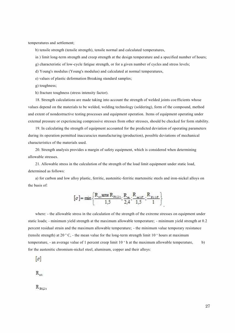
21. Allowable stress in the calculation of the strength of the load limit equipment under static load,
determined as follows:
a) for carbon and low alloy plastic, ferritic, austenitic-ferritic martensitic steels and iron-nickel alloys on
the basis of:
,
where: - the allowable stress in the calculation of the strength of the extreme stresses on equipment under
static loads; - minimum yield strength at the maximum allowable temperature; - minimum yield strength at 0.2
percent residual strain and the maximum allowable temperature; - the minimum value temporary resistance
(tensile strength) at 20 0 C, - the mean value for the long-term strength limit 10 n hours at maximum
temperature, - an average value of 1 percent creep limit 10 n h at the maximum allowable temperature, b)
for the austenitic chromium-nickel steel, aluminum, copper and their alloys:

28
,
Where: - minimum yield strength at 1 percent of the residual strain and the maximum allowable
temperature; - the minimum value of tensile strength (tensile strength) at the maximum allowable
temperature, c) for aluminum casting alloys:
;
g) For titanium and titanium alloys:
;
d) For the sheet metal and rolled tubes of titanium and titanium a lloys:
. 22. Permitted to specify the allowable stress for austenitic steels, the following formula:
.
23. Steel castings for allowable stress value defined by the formulas referred to in paragraphs 21 and 22 of
these requirements, multiplied by 0.8 if subjected to the continuous casting of non-destructive testing, or 0.7 if
the cast were not subjected to a continuous non-destructive testing.
24. In the case of aluminum, copper and alloys thereof are no data on the yield strength and cre ep strength,
the allowable voltage is determined by the following formula:
.

29
25. When designing (design), manufacturing (production) of equipment from non-metallic materials,
non-metallic materials for the values of tensile strength and elastic modulus of rupture correspond to the values
set in the design documentation, and are as follows:
a) for a composite based on carbon roving:
tensile strength [ ] - not less than 160 kgf / mm 2 ,
the modulus of elasticity E - not less than 11,000 kgf / mm 2 ,
b) on the basis of the composite organic roving:
tensile strength [ ] - not less than 170 kgf / mm 2 ,
the modulus of elasticity E - at least 6,500 kgf / mm 2 ,
c) for the composite based stack roving:
tensile strength [ ] - not less than 90 kgf / mm 2 ,
the modulus of elasticity E - at least 5000 kgf / mm 2 .
26. In the equipment as a binder can be used thermoplastic or duroplastic polymeric materials.
temperature curing (polymerization) of the binder should be below the softening temperature of the binde r
material is non-metallic.
Softening temperature of the material should not be below 100 0 C.
27. Welds should not have external or internal defects (damage) which may affect the safety of the
equipment. Minimum values of the mechanical properties of welded joints of equipment should not be below
the minimum values of mechanical characteristics of materials being joined.
28. Input control of welds performed by the equipment manufacturer. NDT methods and its volume
determined by the project developer based equipment need for more accurate and complete identification of
unacceptable defects in view of material properties and characteristics are specified in the design documentation
equipment.
29. In calculating the strength of the welds pieces of equipment allowable stress value is multiplied by a
factor of strength welds < 1. The coefficient is determined by the strength of the welds in the calculation of the
strength of the equipment depending on the material, volume control, welding technology and design of the
weld.
30. For maximum stresses in the ground edge effect or stress concentration, defined on the basis of
numerical analysis, safety factors are set depending on the mechanical characteristics of the materials used and
the type of stress state.
31. Experimental tests of strength equipment carried on the sample. During the tests, it is possible to
observe the critical zones of equipment with the help of test and measurement tools that can reliably detect the
strains and stresses.
32. Pilot testing program includes:
a) pressure test for leaks and strength to confirm there is no leakage of the medium or residual deformations
exceeding permissible values;

30
b) creep tests and fatigue of materials, which takes into account the processes of the equipment;
c) additional tests which take into account other factors, and are held, if necessary.
33. In developing (designing) equipment installed technical performance, minimizing the possibilit y of an
incident of an accident during its operation.
34. Equipment manufactured (made) of materials and supplies provided by the project documentation and
ensure its compliance with safety requirements throughout the life cycle.
35. Equipment manufactured (made) of materials and supplies that are provided in the contract delivery
markings (no damage), which provides the ability to identify with these manufacturer's documentation materials
or intermediate products.
36. Sheets, plates, tubes and forgings used in the manufacture (production) of the equipment shall be
maintained marked with a manufacturer. If there is a semi-finished cutting part, each of them shall bear
identical markings in a manner that was used for the marking materials manufacturer.
37. When selecting materials and (or) for the manufacture of semi-finished products (manufacturing)
equipment is necessary:
a) to identify indicators for the design calculations, as well as the main characteristics of materials and their
processing capability,
b) result in the technical documentation of the data used in the manufacture (production) equipment
materials.
38. In manufacturing (production) of equipment used materials:
a) having the properties (ductility, strength), allowing their use in the operation and withstand the test
equipment. Taken into account when choosing the material or its fragility fracture. When using a brittle material
provides measures to prevent brittle fracture (increased safety factor),
b) having chemical resistance to the working environment for which the equipment is intended. Changes in
chemical and physical properties of materials throughout the design life of equipment or assigned resource
should not lead to disruption of its safe operation
in) suitable for the intended treatments;
g) selected so that when you connect them to each other provides strength equipment during the lifetime of
the equipment.
39. Equipment used in the plastic material is considered, if a tensile test of its elongation after fracture of
not less than 14 percent, and impact strength, determined on specimens with a hub type KCV (c V -notch) is not
less than 27 J / cm2 at a temperature above 20 0 C, but not higher than the lowest permissible temperature.
40. If the production (manufacturing) change the characteristics of the material or residual stresses arise
affecting the safety of the equipment, then held his heat treatment. Type of heat treatment equipment and its
modes are defined by the developer of the project equipment.
41. In manufacturing (production) of equipment and safety devices provided by the manufacturer of the
performance characteristics and parameters of the project documentation in accordance with the safety

31
requirements of technical regulations of the Customs Union "On the safety equipment of high pressure" (TR TC
032/2013) subject to the applicable and a process control system.
42. In manufacturing (production) parts by rolling, stamping, rounding is not allowed change in the
mechanical properties of materials, damage, cracks and other defects that may affect the safety of the equipment.
43. Items of equipment collected together must ensure the safety of equipment and appropriate to its
purpose. All one-piece or welded joints pieces of equipment should be available for non-destructive testing.
44. Equipment equipped with quick-caps should have devices preclude the inclusion of equipment under
pressure when fully closed the lid and the lid opening in the presence of excess pressure equipment.
45. The boiler is installed safety devices, the automatic shutdown of the boiler or its components with
unacceptable deviations from the calculated modes of operation.
46. Piece of equipment, which is limited to the internal volume of isolation valves and pressure which may
increase beyond the allowable shall be equipped with safety devices, automatically preventing the pressure
increase over the allowable working environment by issuing to the atmosphere or the utilizing system.
47. As safety devices are used:
a) lever-freight safety valves direct action;
b) spring-loaded safety valves of direct action;
c) pulse safety device consisting of a pulsed valve and the main safety valve
d) safety devices with membrane disrupting (membrane safety devices).
48. Safety devices are placed in locations accessible for maintenance.
49. Vents from the pressure relief devices and impulse lines impulse safety devices in locations where
condensation forming equipped with drainage pipes to remove condensate.
Installation of valves or other fittings in drainage pipes are not allowed. Wednesday opening of safety
devices and drainage is diverted to a safe place. Discharged highly explosive, toxic environment and
technological group 1 to the closed system for recycling or incineration in an organized system, or the
atmosphere - for gas density relative to air of 0.8 or less.
Forbidden to combine discharges containing substances that are capable of when mixed to form an
explosive mixture or unstable compounds.
50. Construction of pipelines connecting the safety devices (of lead, which discharge and drainage) should
exclude the possibility of freezing them in the work environment.
When installed on a pipe or conduit several safety devices cross-sectional area of the nozzle or piping shall
not be less than the total cross-sectional area of 1.25 installed on it safety valves. In determining the length of
the pipe connecting section 1000 mm counted value of its linear resistance (pressure loss).
51. Lever-truck safety valve or pressure relief valve is equipped with a spring device to check the health of
their actions during the operation of the equipment by the forced opening.
Impulse safety valve is equipped with a device enabling the forced opening of the safety valve remotely via
the control panel.

32
Construction spring safety valves shall be designed to tightening spring above the value set by regulation to
operate at a given pressure. Spring safety valves are protected from unacceptable heating or cooling, as well as
from direct exposure to the working environment.
52. Equipment designed for an operating pressure which is less than the supply pressure of its source, is
equipped with the water supply pipeline automatic mounting device with a reducing pressure gauge and safety
valve mounted on the side of lower pressure after the reducing device.
Reduction and cooling devices provide automatic temperature control. If you install a bypass line (bypass),
it is also equipped with a reducing device.
53. For a group of vessels that operate at the same pressure, the one permitted for the reducing device with
manometer and a safety valve on a common mounting the supply pipe to the first branch to one of the
vessels. In this case, the installation of safety devices on the vessels themselves is not necessary if they
excluded the possibility of increasing pressure.
If a reducing automatic device due to the physical properties of the working environment may not work
reliably, not install a flow regulator, with provision for protection against pressure increase.
54. Number of safety valves, their size and bandwidth are determined so that the equipment does not
produce overpressure exceeding the maximum allowable working pressure:
a) more than 0.05 MPa - for vessels in which the excess pressure is less than 0.3 MPa
b) 15 percent - of the receptacles in which the excess pressure is between 0.3 to 6 MPa, inclusive;
c) 10 percent - of the receptacles in which the overpressure is greater than 6 MPa.
55. When working overpressure relief valves in the vessel is allowed no more than 25 percent of th e
maximum allowable working pressure, provided that the excess provided guidance (instruction) operating the
vessel.
56. Safety valves must protect boilers, super heaters, economizers and pipelines on the excess pressure in
them for more than 10 percent of the maximum allowable working pressure. Excess pressure safety valves fully
open for more than 10 percent of the maximum allowable working pressure allowed in the case provided for the
calculation of the strength of the boiler, superheated, economizer and pipeline.
57. In steam boilers with a working pressure up to 4 MPa (except mobile boilers and boiler steam capacity
of less than 35 t / h) set only impulse safety valves. On mobile boiler plants may not be mounted lever-truck
safety valves.
58. At each steam boiler on and off working environment superheated safety valves are installed. Number
and their installation are determined by the development (design).
Total capacity of boilers installed safety devices shall not be less than the nominal capacity of the
equipment.
59. Capacity of the relief valves is confirmed by the relevant tests of prototype model of the safety valve of
this design, carried out by the manufacturer and indicated in the passport equipment.
60. Safety devices for steam and hot water boilers are installed on sockets or pipes directly connected to

33
boilers, as follows:
a) in steam boilers with natural circulation without superheated - on the upper drum or steam drum;
b) on steam boilers ramjet, as well as boilers forced circulation - on the weekends collectors or vapor outlet
conduit;
c) on the hot-water boilers - on the weekends or collectors drum;
g) on reheated is possible to install all safety devices on the input side of the superheated steam;
e) disconnected the water economizers - not less than 1 safety device on the outlet and inlet water.
61. In the presence of the boiler superheated non disconnectable part of the safety valves with a capacity
of not less than 50 percent of the rated output of the boiler is mounted on the superheated outlet header.
62. In steam boilers with a working pressure up to 4 MPa impulse safety valves installed on indirect non
disconnectable superheater outlet header or steam line to the main shut-off valves, While at the drum boilers for
50 percent of the valves on the total bandwidth selection for a couple of pulses produced by a boiler drum.
When an odd number of identical valve allowed steam extraction for pulses from the drum for not less than
one-third but not more than one second valve installed on the boiler. On block units in the case of placing the
safety valves on steam line directly from the turbines allowed for the momenta of all the safety valves to use
superheated steam, with 50 percent of valves supplied additional electrical pulse from the contact pressure
gauge connected to the boiler drum.
When an odd number of identical safety valves may be supplied additional electrical pulse from the contact
manometer, connected to the boiler drum, no less than one third but no more than one second valve.
63. For boiler economizers disconnected installation location of safety valves, adjust their technique and
their discovery of the pressure determined by the designer.
ramjet On steam boilers, which during firing or stop the boiler first (along the water) of the surface heating
is disconnected from the rest of the heating surface VALVES must install, the number and size of safety valves
for the first part of the heating surface are determined by the design documentation.
64. Diaphragm safety devices are installed
on vessels and pipelines:
a) if the lever-freight and spring-loaded safety valves can not be applied due to their inertia or fo r other
reasons;
b) before the safety valves in case the safety valves may not work reliably due to the harmful effects of
working environment (corrosion, erosion, polymerization, crystallization, sticking, freezing) or possible leaks
through the closed valve highly explosive, toxic, environmentally harmful substances. In this case, the
equipment shall be a device that allows you to check the integrity of the membrane,
c) in parallel with safety valves to increase the capacity of the pressure relief systems;
g) on the output side of the safety valves to prevent the harmful effects of working environments from the
relief system and to eliminate the influence vibrations from the backpressure of the system reliability of the
safety valves.

34
65. Necessity and place of installation of membrane safety devices, as well as their structure determined by
the project equipment. Protective membranes are installed only in their designated mountings.
Diaphragm safety devices are located in places that are open and accessible for inspection, mounting and
dismounting. The connecting pipes are protected from freezing in their working environment, and safety
devices are installed themselves on sockets or pipes directly connected to the equipment .
When installing diaphragm safety devices in series with the pressure relief valve (valve before or behind)
the space between the disc and the safety valve outlet tube is reported pressure gauge with alarm (for the control
of serviceability membranes).
Allowed to install the device before switching membrane safety devices in the presence of twice the
number of membrane devices while providing protection of equipment from overpressure at any position of the
switching device.
66. To control the level of liquid in the equipment having the media interface, apply the liquid level
measuring instruments working environment. Along with liquid level indicator on the equipment installed
sound, light and other signaling and blocking limit fluid levels.
67. On the boiler, except the ram, and the heated flame or flammable gases vessel, which may drop below
the allowable liquid level is set at least two liquid level indicator of direct action.
Allowed further as duplicate set liquid level indicators indirect action. The number and place of installation
of the liquid level indicator in boilers (including evaporation step with drums or the external separator) except
boiler uniflow and flame-heated or combustible gases defined by the draft vessels equipment.
68. Liquid level indicator of direct action must have an independent connection to equipment. You can
install two pointers liquid level direct action on the connecting tube (column) with a diameter of not less than 70
mm.
Installing on fluid levels of direct action intermediate flanges and valves, except sensors liquid level switch
is not allowed. This requirement shall not apply to the flanges valves, which is part of the level indicator.
Connecting to a liquid level indicator of direct action and its connecting pipes or fittings other devices is
not allowed except for point level sensor liquid, if it does not work broken dipstick liquid.
69. Configuration pipes connecting the liquid level indicators with the equipment must exclude education in
their water bags and allow pipe cleaning. Connecting pipes should be protected from thermal heating fuel
combustion products and from freezing.
70. Liquid level indicators of direct action and highlights arranged so that the fluid level was visible from
the workplace staff. On equipment with operating pressures up to 4 MPa liquid level indicators are supplied
with covers direct action to protect personnel in the event of destruction of transparent plates.
71. The width of the slit observation of liquid level indicator defined by the project equipment.
72. Liquid level indicators are provided with isolation valves to disconnect them from the equipment and
purge. On valving specified (molded, stamped or marked with paint) direction of opening and closing, and on
tap further stated his position orifice. Inner diameter of the passage of valves must be at least 8 mm. To drain

35
water when flushing liquid level indicator provides a funnel with a protective device and ou tlet pipe for draining
equipment.
73. At a pressure of 4.5 MPa equipment more liquid level indicators are supplied with two successive sets
of shut-off valves to disconnect them from the equipment.
74. If the distance from the ground, which made observation of the liquid level in the equipment to liquid
level indicator of direct action is more than 6 m, and if the fluid level is not visible from the workplace
attendants, set 2 discount remote liquid level indicator. In this case, the installation equipment 1 may be a liquid
level gauge direct action.
Lowered remote fluid level indicator connected directly to the equipment fittings are independently
separate from other liquid level indicator and are soothing device.
75. On recovery boilers and boilers energy technology remote liquid level indicators are installed on the
remote (remote) data management boilers.
76. Steam boilers equipped with electric automatic power off when the level is below the maximum
permissible level.
77. Boilers equipped with automatic audible and visual alarms upper and lower limits of water. Similar
alarms should act on all parameters, which are triggered by the automatic stop devices and safety equipment.
78. Steam boilers, regardless of type and steam equipped with automatic controls feed water. Steam boilers
with steam temperature at the outlet of the main or reheated more than 400 0 C are equipped with automatic
devices for controlling the temperature of steam.
79. Boilers with a superheated, each to the main steam line isolation valves are provided means for
measuring the temperature of the superheated steam. Boilers with reheat steam temperature measuring means
mounted on the input and output pair.
80. Boilers with natural circulation and superheating steam performance of more than 20 t / h, once -through
boilers with a capacity of more than 1 ton of steam / h with measurement instruments showing provide
measurement tools with continuous recording quantities of superheated steam temperature.
81. Superheats on multiple parallel sections besides amount measuring means steam temperature steam
lines installed on common superheated steam, set means periodic measurements of the steam temperature at the
outlet of each section, and steam boilers with a steam temperature of 500 0 C - the output of the steam heater
coils on one means of measurement for each meter width flue.
82. In steam boilers with a capacity of more than 400 tons of steam / h on the output of the superheated
coils installed measurement tools with continuous recording temperature value pair. In steam boilers with de
superheats for controlling the magnitude of the superheat steam superheated to and after the established means
of measuring the corresponding quantities.
83. At the inlet of water to the economizer and the economizer outlet Water and the feed water piping for
boilers without economizer means are provided measuring the temperature of the feed water.
84. On hot water boilers measuring water temperature set on the water inlet and outlet boiler water from the
36
boiler.
85. On hot water boilers with a capacity of more than 4.19 tons of steam / h installed recording equipment
measuring the water temperature at the outlet of the boiler.
86. To control the temperature of the metal and preventing its increase beyond acceptable values for
kindling stops and maneuvering modes boiler provides means for measuring the temperature of the walls of its
elements. The retrofitting of measuring temperature, their number and location determined by the project
developer boiler.
87. Vessels operating under varying temperature walls are fitted with temperature measurements to control
the rate and uniformity of warming the body of the vessel length and height, as well as pointers thermal
displacement. The need to equip vessels means of temperature measurement and thermal displacement pointers
allowable heating rate and cooling vessels are determined by the project developer and the vessel spec ified by
the manufacturer of the equipment or in the passport in the user manual (instruction) manual.
88. Equipment and its separate cavities with different values of pressure measuring devices are equipped
with direct pressure.
89. Steam boilers with a capacity of more than 10 tons of steam / h and hot water boilers with a capacity of
more than 21 pair GJ / h must be fitted with a means of measuring the pressure recording.
90. Pressure measuring devices are placed:
a) on the boiler drum,
b) on the boiler superheated steam superheated in front of the main shut-off valves;
c) on the fitting of the vessel or pipe between the vessel and stop valves;
g) on a continuous-flow boiler superheated in front of the main shut-off valve.
91. On hot water boilers pressure measuring devices are placed on the water inlet and outlet boiler water
from the boiler to the valves.
92. Class pressure measuring accuracy must be at least:
a) 2.5 - operating at a pressure of not more than 2.5 MPa,
b) 1.5 - operating at a pressure of from 2.5 to 14 MPa inclusive,
c) 1 - with an operating pressure greater than 14 MPa.
93. When installing the measuring pressure at an altitude of more than 5 m provides a means of measuring
the pressure duplicate.
94. Hardware design provides an opportunity to secure a purge and check off pressure measuring devices.
95. Valve type, its amount and position of the developer of the project are determined on the b asis of
equipment and safety equipment provided by the project outages and its elements.
96. When a group of feed water in boiler pump head is selected to meet the requirements of technical
regulations of the Customs Union "On the safety equipment of high pressure" (TR TC 032/2013), as well as the
basis of providing the boiler feed with the highest working pressure or maximum head loss in the feed water
line.

37
97. Water supply nutrients devices is determined by the nominal capacity steam boilers based on the flow
of water on a continuous or periodic purging steam cooled condenser, maintenance-reducing cooling and
cooling devices, as well as the potential loss of water or steam.
98. Type, characteristics, quantity and circuit of the nutrient devices provide safe operation of the boiler
during operation, including emergency stop.
99. In developing (designing) of piping must be:
a) for pipes with nominal diameter of 150 mm with the working environment of 300 0 C or more in the
project to determine the necessary number of indicators for monitoring the movements of thermal expansion of
the piping and monitoring correct operation of the overhead system;
b ) to provide a device for condensate removal in cases where the inside of pipes tr ansporting vaporous
working environments, it may be education. These devices must be located in the lower points of the piping;
c) consider the possibility of damage caused by violations of the hydraulic regime, as well as the
erosion-corrosion wear;
g) provide for measures and means to reduce vibration and eliminate the possibility of accidental
destruction and depressurization of pipelines, which during operation subjected to vibration
d) provide devices which cut the branch pipeline in those cases where these pipelines are contained Fluids
group 1;
e) to minimize the risk of accidental release of the working environment. Sampling site working
environment must be clearly marked with the name of the working environment;
g) develop technical documentation for underground piping that contains the information necessary for safe
maintenance, inspection and repair (steel grade, diameter, pipe thickness, length of the pipeline, the location of
poles , expansion joints, hangers, valves, air-vent and drainage devices, welded joints and the distance between
them and from them to the wells and user inputs, the location pointer for the control of the pipeline and the
parameters of the working environment).
100. Recompression chamber design must allow inspection (including inner surface), cleaning, washing,
flushing and repair of pressure chamber.
101. When designing (design) pressure chambers accounted stresses of installation and under the influence
of inertial forces.
102. Length of stay of people in the chamber defined by the project and indicated in the passport. In the
case of a long stay in the chamber provides people with different compartments functional purpose.
103. Equipment project should include grommets or glands high pressure electric cables, provides
mechanical strength, axial and radial leak-tight cable glands in general and its conductive elements, and
dielectric strength throughout the range of pressures in the chamber.
104. Recompression chamber design must be capable of opening pressure chambers inside and
outside. Must not be used for constipation closing doors or covers in a recompression chamber.
105. For visual or television monitor the situation inside the hyperbaric chambers and lighting interior
38
space project equipment provided portholes fitted outer cover, which protects the glass porthole from
mechanical damage.
When designing (design), manufacturing (production) of hyperbaric chambers used portholes light
transmitting materials with safety not less than safety margin body hyperbaric chambers and light transmission
of not less than 85 percent.
106. The project provided equipment air supply and gas supply for the following purposes:
a) forming a gaseous medium in the chamber,
b) providing for the permanent respiratory system,
c) the maintenance and change of pressure in the chamber;
g) maintaining and changing the composition of the gaseous medium in the chamber of oxygen and
indifferent gases;
d) locking.
107. Air supply systems and gas provided by an increase in pressure in the chamber at a rate not less than
0.2 MPa / min. a pressure from 0.1 MPa to 1.7 inclusive (1 - 17 kgf / cm 2 ) not less than 0.1 MPa / min. (1 kgf /
cm 2 - for pressures greater than 1.7 MPa (17 kgf / cm 2 ) and maintain pressure to within ± 0,025 MPa
(0.25 kgf / cm 2 ). Reducing the pressure in the pressure chamber is produced with a rate of 0.003 - 0.9 MPa / h
(0.03 - 9 kgf / cm 2
108. Means of gas control pressure chambers must ensure the accuracy of measurements of oxygen, helium
and carbon dioxide, as well as the possible harmful substances.
109. System and fire protection should ensure that an outbreak of fire in the chamber or prerequisites fire
(smoke, uncontrolled rise in temperature), activate an alarm and extinguishing fire detection by all available
means in the chamber.
110. Means the automatic control must provide a safe environment people stay inside hyperbaric chambers.
111. Each compartment is equipped with a recompression chamber and gateway pressure gauge, which is
mounted outside on the nipple, welded to the shell hyperbaric chambers, or in the control systems of hyperbaric
chambers.
112. Power networks recompression chamber should have backup power sources to ensure smooth
operation of elements of air and gas systems, and fire protection.
113. All protective and switching-power electric ballasts mounted outside pressure chambers. Power cables
in the chamber must be non-combustible insulation. The project should provide hyperbaric chambers protection
system from static electricity, the possibility of grounding internal removable metal products, equipment and
hyperbaric chambers housing.
114. Project equipment is determined by the need to install lighting. Fixtures installed in hyperbaric
chambers, should be sealed, designed for working pressure environment.
115. The project provides an opportunity to use the equipment of communication with people inside the
hyperbaric chambers.

39
116. Pipelines, steam and water heaters, installed inside the hyperbaric chambers, and pipelines supplying
compressed air and gas mixtures that are installed outside the pressure chambers, designed seamless copper
pipes or stainless steel pipes.
117. Hyperbaric chambers for domestic equipment used incombustible (PROTECTED) materials
guaranteed by releasing hazardous substances in a gaseous medium pressure chambers.
ANNEX number 3
to the technical regulations of the Customs Union
"On the security of equipment operating under positive pressure "
(TR TC 032/2013)
REQUIREMENTS a distinctive color and identity I. Cylinders
Name of gas Coloring cylinders The label text Color printing Color stripes
1 2 3 4 5
Nitrogen black nitrogen yellow brown
Ammonia yellow ammonia black -
Argon crude black crude argon white white
Argon Technology black Argon Technology blue blue
Argon clean gray pure argon green green
Acetylene White acetylene red _
Butylene red butylene yellow black
Naftogaz gray neftegaz red _
Butane red butane white _
Hydrogen dark green hydrogen red _
Air black compressed air white _
Helium brown helium white _
Nitrous oxide gray nitrous oxide black _
Oxygen Blue oxygen black _
Medical oxygen Blue Medical oxygen black _
Hydrogen sulfide White hydrogen sulfide red red
Sulfur dioxide black sulfur dioxide white yellow

40
Carbon dioxide black carbon dioxide yellow _
Phosgene Protective _ _ red
Freon-11 aluminum Freon-11 black blue
Freon-12 aluminum Freon-12 black _
Freon-13 aluminum Freon-13 black 2 red
Freon-22 aluminum Freon-22 black 2 yellow
Chlorine Protective _ _ green
Cyclopropane Orange cyclopropane black _
Ethylene Purple ethylene red _
All other combustible
gases
red name of the gas white _
All other
non-combustible
gases
black name of the gas yellow _
Notes: 1. The inscription is applied on the circumferential cylinder length of not less than 1/3 the
circumference, while the band - the entire circumference. The height of the letters on cylinders with a
capacity of more than 12 liters to be 60 mm, while the width of the strip - 25 mm. On cylinders up to
12 l size of the letters and stripes should be determined depending on the lateral surface of the
cylinder.
2. Allowed to paint in gray or yellow color of small cylinders (12 liters) for breathing ap paratus and
self-rescuers with compressed air.
II. Tank trucks for transportation of liquefied petroleum gas The outer surface of tank trucks for transportation of liquefied petroleum gas is painted in a light gray
color. On both sides of the vessel applied distinctive red stripe width of 200 mm with an inscription in black
over it "Propane - flammable." At the bottom of the vessel is put back black inscription "flammable".
ANNEX number 3
to the Technical Regulations of the Customs Union
"On the security of equipment operating under positive pressure "
(TR TC 032/2013)

41
REQUIREMENTS a distinctive color and identity I. Cylinders
Name of gas Coloring cylinders The label text Color printing Color stripes
1 2 3 4 5
Nitrogen black nitrogen yellow brown
Ammonia
yellow ammonia black -
Argon crude black crude argon white white
Argon Technology black Argon Technology blue blue
Argon clean gray pure argon green green
Acetylene White acetylene red _
Butylene red butylene yellow black
Naftogaz gray neftegaz red _
Butane red butane white _
Hydrogen dark green hydrogen red _
Air black compressed air white _
Helium brown helium white _
Nitrous oxide gray nitrous oxide black _
Oxygen Blue oxygen black _
Medical oxygen Blue Medical oxygen black _
Hydrogen sulfide White hydrogen sulfide red red
Sulfur dioxide black sulfur dioxide white yellow
Carbon dioxide black carbon dioxide yellow _
Phosgene Protective _ _ red
Freon-11 aluminum Freon-11 black blue
Freon-12 aluminum Freon-12 black _
Freon-13 aluminum Freon-13 black 2 red
Freon-22 aluminum Freon-22 black 2 yellow

42
Chlorine Protective _ _ green
Cyclopropane Orange cyclopropane black _
Ethylene Purple ethylene red _
All other combustible
gases
red name of the gas white _
All other
non-combustible
gases
black name of the gas yellow _
Notes: 1. The inscription is applied on the circumferential cylinder length of not less than 1/ 3 the
circumference, while the band - the entire circumference. The height of the letters on cylinders with a
capacity of more than 12 liters to be 60 mm, while the width of the strip - 25 mm. On cylinders up to
12 l size of the letters and stripes should be determined depending on the lateral surface of the
cylinder.
2. Allowed to paint in gray or yellow color of small cylinders (12 liters) for breathing apparatus and
self-rescuers with compressed air.
II. Tank trucks for transportation of liquefied petroleum gas The outer surface of tank trucks for transportation of liquefied petroleum gas is painted in a light gray
color. On both sides of the vessel applied distinctive red stripe width of 200 mm with an inscription in black
over it "Propane - flammable." At the bottom of the vessel is put back black inscription "flammable".