Embed Size (px)
Citation preview

Pos: 2 /DinA-4 -- Online/00_Titel/6228 / WS-1 @ 44\mod_1443772028039_0.docx @ 395407 @ @ 1
1473-1-8811 / 2CKA001473B8811 │ 19.05.2016
Technical Reference Manual ABB-free@home®
Weather station WS-1
=== Ende der Liste für Textmarke Titel ===
Table of contents
Technical Reference Manual 1473-1-8811 / 2CKA001473B8811 │2
Pos: 4 /DinA-4 -- Online/00_IVZ/IVZ - 2-Überschriftenebenen @ 39\mod_1415276617885_15.docx @ 305452 @ @ 1 Table of contents
1 Notes on the instruction manual ................................................................................................................................. 3 2 Safety .......................................................................................................................................................................... 4
2.1 Information and symbols used ........................................................................................................................ 4 2.2 Intended use ................................................................................................................................................... 5 2.3 Improper use .................................................................................................................................................. 5 2.4 Target group / Qualifications of personnel ...................................................................................................... 5 2.5 Safety instructions .......................................................................................................................................... 6 2.6 Environment ................................................................................................................................................... 7
3 Setup and function ...................................................................................................................................................... 8 3.1 Scope of supply .............................................................................................................................................. 9 3.2 Overview of types ........................................................................................................................................... 9 3.3 Functions ........................................................................................................................................................ 9 3.4 Device overview ........................................................................................................................................... 10
4 Technical data ........................................................................................................................................................... 11 4.1 Dimensional drawings .................................................................................................................................. 11
5 Connection, installation / mounting ........................................................................................................................... 12 5.1 Planning instructions .................................................................................................................................... 12 5.2 Safety instructions ........................................................................................................................................ 12 5.3 Circuit diagrams ............................................................................................................................................ 13 5.4 Mounting ....................................................................................................................................................... 13
6 Commissioning ......................................................................................................................................................... 16 6.1 Allocation of devices and definition of channels ........................................................................................... 16 6.2 Setting options per channel .......................................................................................................................... 20 6.3 Links ............................................................................................................................................................. 23
7 Update ...................................................................................................................................................................... 25 8 Operation .................................................................................................................................................................. 25 9 Maintenance ............................................................................................................................................................. 25 10 Notes ......................................................................................................................................................................... 26 11 Index ......................................................................................................................................................................... 27
=== Ende der Liste für Textmarke Inhaltsverzeichnis ===

Notes on the instruction manual
Technical Reference Manual 1473-1-8811 / 2CKA001473B8811 │3
Pos: 7 /DinA-4 -- Online/1 Überschrift/Hinweise zur Anleitung @ 39\mod_1416582883599_15.docx @ 306718 @ 1 @ 1
1 Notes on the instruction manual
Pos: 8 /DinA-4 -- Online/Hinweise zur Anleitung/Hinweise zur Anleitung @ 41\mod_1422785781401_15.docx @ 333255 @ @ 1
Please read through this manual carefully and observe the information it contains. This will assist you in preventing injuries and damage to property, and ensure both reliable operation and a long service life for the device.
Please keep this manual in a safe place.
If you pass the device on, also pass on this manual along with it.
ABB accepts no liability for any failure to observe the instructions in this manual.
If you require additional information or have questions about the device, please contact ABB or visit our Internet site at:
www.BUSCH-JAEGER.com
Pos: 9 /Systemmodule/++++++++++++++ Seitenumbruch +++++++++++++++ @ 41\mod_1422789416992_0.docx @ 333487 @ @ 1
Safety
Technical Reference Manual 1473-1-8811 / 2CKA001473B8811 │4
Pos: 11 /DinA-4 -- Online/1 Überschrift/Sicherheit @ 39\mod_1416582987700_15.docx @ 306733 @ 1 @ 1
2 Safety
Pos: 12 /DinA-4 -- Online/Sicherheit/01_Einleitung/Einleitung @ 41\mod_1422786182526_15.docx @ 333272 @ @ 1
The device has been constructed according to the latest valid regulations governing technology and is operationally reliable. It has been tested and left the factory in a technically safe and reliable state.
However, residual hazards remain. Read and adhere to the safety instructions to prevent hazards of this kind.
ABB accepts no liability for any failure to observe the safety instructions. Pos: 13 /DinA-4 -- Online/1.1 Überschrift/Verwendete Hinweise und Symbole @ 41\mod_1422789083005_15.docx @ 333454 @ 2 @ 1
2.1 Information and symbols used Pos: 14 /DinA-4 -- Online/Sicherheit/Verwendete Symbole/Teil 1 @ 41\mod_1422788224605_15.docx @ 333438 @ @ 1
The following Instructions point to particular hazards involved in the use of the device or provide practical instructions.
Danger Risk of death / serious damage to health – The respective warning symbol in connection with the signal word "Danger"
indicates an imminently threatening danger which leads to death or serious (irreversible) injuries.
Warning Serious damage to health – The respective warning symbol in connection with the signal word "Warning"
indicates a threatening danger which can lead to death or serious (irreversible) injuries.
Caution Damage to health – The respective warning symbol in connection with the signal word "Caution"
indicates a danger which can lead to minor (irreversible) injuries.
Attention Damage to property – This symbol in connection with the signal word "Attention" indicates a
situation which could cause damage to the product itself or to objects in its surroundings.
NOTE This symbol in connection with the word "Note" indicates useful tips and recommendations for the efficient handling of the product.
The following safety symbols are used in the operating manual. Pos: 15 /DinA-4 -- Online/Sicherheit/Verwendete Symbole/Teil n -- Eletrische Gefährdung @ 41\mod_1422789187092_15.docx @ 333470 @ @ 1
This symbol alerts to electric voltage.
Pos: 16 /Systemmodule/++++++++++++++ Seitenumbruch +++++++++++++++ @ 41\mod_1422789416992_0.docx @ 333487 @ @ 1
Safety
Technical Reference Manual 1473-1-8811 / 2CKA001473B8811 │5
Pos: 17 /DinA-4 -- Online/1.1 Überschrift/Bestimmungsgemäßer Gebrauch @ 41\mod_1422618579097_15.docx @ 332102 @ 2 @ 1
2.2 Intended use Pos: 18 /DinA-4 -- Online/Sicherheit/Bestimmungsgemäßer Gebrauch/6228 / WS-1 @ 44\mod_1443772884355_15.docx @ 395443 @ @ 1
The device is a weather station for surface-mounting on buildings.
Depending on the setting, the movement detector responds to body heat and switches on the lights.
The device is intended for the following: ■ Operation according to the listed technical data ■ Installation on walls of buildings ■ Use with the connecting options available on the device
The intended use also includes adherence to all specifications in this manual. Pos: 19 /Systemmodule/- - - - - - Abstand - - - - - - @ 41\mod_1422791984802_0.docx @ 333519 @ @ 1
Pos: 20 /DinA-4 -- Online/1.1 Überschrift/Bestimmungswidriger Gebrauch @ 41\mod_1422786865873_15.docx @ 333288 @ 2 @ 1
2.3 Improper use Pos: 21 /DinA-4 -- Online/Sicherheit/Bestimmungswidriger Gebrauch/Teil 1 @ 41\mod_1422787173164_15.docx @ 333322 @ @ 1
Each use not listed in Chapter 2.2 “Intended use“ on page 5 is deemed improper use and can lead to personal injury and damage to property.
ABB is not liable for damages caused by use deemed contrary to the intended use of the device. The associated risk is borne exclusively by the user/operator.
The device is not intended for the following: ■ Unauthorized structural changes ■ Repairs
Pos: 22 /DinA-4 -- Online/Sicherheit/Bestimmungswidriger Gebrauch/Teil n -- Busankoppler @ 43\mod_1438597604334_15.docx @ 371000 @ @ 1
■ Insert with an additional bus coupler Pos: 23 /Systemmodule/- - - - - - Abstand - - - - - - @ 41\mod_1422791984802_0.docx @ 333519 @ @ 1
Pos: 24 /DinA-4 -- Online/1.1 Überschrift/Zielgruppe / Qualifikation des Personals @ 41\mod_1422787011344_15.docx @ 333305 @ 2 @ 1
2.4 Target group / Qualifications of personnel Pos: 25 /DinA-4 -- Online/Sicherheit/Qualifikation des Personals/Installation, Inbetriebnahme und Wartung @ 41\mod_1422787983324_15.docx @ 333421 @ @ 1
Installation, commissioning and maintenance of the device must only be carried out by trained and properly qualified electrical installers.
The electrical installer must have read and understood the manual and follow the instructions provided.
The electrical installer must adhere to the valid national regulations in his/her country governing the installation, functional test, repair and maintenance of electrical products.
The electrical installer must be familiar with and correctly apply the "five safety rules" (DIN VDE 0105, EN 50110):
1. Disconnect 2. Secure against being re-connected 3. Ensure there is no voltage 4. Connect to earth and short-circuit 5. Cover or barricade adjacent live parts
Pos: 26 /Systemmodule/++++++++++++++ Seitenumbruch +++++++++++++++ @ 41\mod_1422789416992_0.docx @ 333487 @ @ 1

Safety
Technical Reference Manual 1473-1-8811 / 2CKA001473B8811 │6
Pos: 27 /DinA-4 -- Online/1.1 Überschrift/Sicherheitshinweise @ 41\mod_1422793473426_15.docx @ 333552 @ 2 @ 1
2.5 Safety instructions Pos: 28 /DinA-4 -- Online/11_Sicherheitshinweise/Gefahr/Gefahr -- 230 V -- Gerät für Aussenbereich @ 44\mod_1443774216757_15.docx @ 395460 @ @ 1
Danger - Electric voltage! Electric voltage! Risk of death and fire due to electric voltage of 230 V. Dangerous currents flow through the body when coming into direct or indirect contact with live components. This can result in electric shock, burns or even death. ■ Work on the 230 V supply system may only be performed by authorised and
qualified electricians. ■ Disconnect the mains power supply before installation or dismantling. ■ Never use the device with damaged connecting cables. ■ Do not open covers firmly bolted to the housing of the device. ■ Use the device only in a technically faultless state. ■ Do not make changes to or perform repairs on the device, on its components
or its accessories.
Pos: 29 /DinA-4 -- Online/11_Sicherheitshinweise/Vorsicht/Vorsicht -- Heiße Oberfläche -- 6228 / WS-1 @ 44\mod_1443776596181_15.docx @ 395495 @ @ 1
Caution - hot surface! The rain sensor is hot during operation. ■ Do not touch the rain sensor.
Pos: 30 /Systemmodule/++++++++++++++ Seitenumbruch +++++++++++++++ @ 41\mod_1422789416992_0.docx @ 333487 @ @ 1
Safety
Technical Reference Manual 1473-1-8811 / 2CKA001473B8811 │7
Pos: 32.1 /DinA-4 -- Online/1.1 Überschrift/Umwelt @ 41\mod_1422618733212_15.docx @ 332118 @ 2 @ 1
2.6 Environment Pos: 32.2 /DinA-4 -- Online/Hinweise zum Umweltschutz/Module/Hinweis -- Entsorgung Elektrogeräte @ 45\mod_1449830509974_15.docx @ 406121 @ @ 1
Consider the protection of the environment! Used electric and electronic devices must not be disposed of with domestic waste. – The device contains valuable raw materials which can be recycled.
Therefore, dispose of the device at the appropriate collecting depot.
Pos: 32.3 /DinA-4 -- Online/Hinweise zum Umweltschutz/Module/Entsorgung kennzeichnungspflichtiger Materialien @ 47\mod_1461049742799_15.docx @ 651717 @ @ 1
All packaging materials and devices bear the markings and test seals for proper disposal. Always dispose of the packaging material and electric devices and their components via the authorized collecting depots and disposal companies.
The products meet the legal requirements, in particular the laws governing electronic and electrical devices and the REACH ordinance.
(EU Directive 2012/19/EU WEEE and 2011/65/EU RoHS)
(EU REACH ordinance and law for the implementation of the ordinance (EC) No.1907/2006).
Pos: 33 /Systemmodule/++++++++++++++ Seitenumbruch +++++++++++++++ @ 41\mod_1422789416992_0.docx @ 333487 @ @ 1

Setup and function
Technical Reference Manual 1473-1-8811 / 2CKA001473B8811 │8
Pos: 35 /DinA-4 -- Online/1 Überschrift/Aufbau und Funktion @ 39\mod_1416583230426_15.docx @ 306763 @ 1 @ 1
3 Setup and function
Pos: 36 /DinA-4 -- Online/Aufbau und Funktion/01_Einleitung/Einleitung -- 6228 / WS-1 @ 44\mod_1443778106239_15.docx @ 395530 @ @ 1
Fig. 1: Product overview
[1] Brightness sensor [2] Rain sensor with heating (optional) [3] LED and push-button for positioning during commissioning and for booting [4] Wind wheel [5] Temperature sensor
The weather station (with bus coupler) must only be integrated in a free@home system. Here, for example, it can be assigned to existing switch actuators to control automated functions. The devices detect temperature, brightness and wind speed. They have not been pre-programmed. Also a rain sensor has been installed on the top side. This can also activated as an option (additional power supply via 110 to 230 V necessary). The weather data can be displayed via the web-based user interface of the System Access Point and the free@home- app.
The integrated bus coupler makes possible the connection to the free@home bus line.
NOTE Rain is only detected when the rain sensor is sufficiently moist. There could be a delay between the first rain drop of a shower and the time the rain is detected. After the rain has stopped, and in spite of the heating, it can also take several minutes until the sensor is dry again and this is detected by the device. The temperature value can be affected by direct exposure to sunlight.
Pos: 37 /Systemmodule/++++++++++++++ Seitenumbruch +++++++++++++++ @ 41\mod_1422789416992_0.docx @ 333487 @ @ 1

Setup and function
Technical Reference Manual 1473-1-8811 / 2CKA001473B8811 │9
Pos: 38 /DinA-4 -- Online/1.1 Überschrift/Lieferumfang @ 43\mod_1438601277354_15.docx @ 371052 @ 2 @ 1
3.1 Scope of supply Pos: 39 /DinA-4 -- Online/Aufbau und Funktion/Lieferumfang/Lieferumfang -- 6228 / WS-1 @ 44\mod_1443779513069_15.docx @ 395564 @ @ 1
The device including wall bracket is contained in the scope of supply.
Pos: 40 /DinA-4 -- Online/1.1 Überschrift/Typenübersicht @ 43\mod_1438601386366_15.docx @ 371069 @ 2 @ 1
3.2 Overview of types Pos: 41 /DinA-4 -- Online/Aufbau und Funktion/Typenübersicht/Typenübersicht -- 6228 / WS-1 @ 44\mod_1443780637777_15.docx @ 395611 @ @ 1
Sensor channels Article number Product name
1 WS-1 Weather station
Table 1: Overview of types
Pos: 42 /DinA-4 -- Online/1.1 Überschrift/Funktionen @ 42\mod_1428652286122_15.docx @ 349986 @ 2 @ 1
3.3 Functions Pos: 43 /DinA-4 -- Online/Aufbau und Funktion/Funktion/Funktion -- 6228 / WS-1 @ 44\mod_1443780955966_15.docx @ 395628 @ @ 1
The following table provides an overview of the possible functions and applications of the device:
Icon of the operating surface Information
Name: Weather station
Type: Sensor
Made available by: Weather station
Function:
Sensor for the control of free@home functions dependent on the weather data Temperature and wind speed). Rain sensor is optional.
Table 2: Overview of functions
Pos: 44 /Systemmodule/++++++++++++++ Seitenumbruch +++++++++++++++ @ 41\mod_1422789416992_0.docx @ 333487 @ @ 1

Setup and function
Technical Reference Manual 1473-1-8811 / 2CKA001473B8811 │10
Pos: 45 /DinA-4 -- Online/1.1 Überschrift/Geräteübersicht @ 43\mod_1438602324753_15.docx @ 371139 @ 2 @ 1
3.4 Device overview Pos: 46 /DinA-4 -- Online/Aufbau und Funktion/Geräteübersicht/Geräteübersicht -- 6228 /WS-1 @ 44\mod_1443781915172_15.docx @ 395645 @ @ 1
Fig. 2: Overview of wall bracket and weather station
[1] Plug-in terminal for mains voltage [2] Bus connection terminal [3] Washer [4] Rubber seal/cable screw gland [5] Fastening screw for wall bracket [6] Screw for cover [7] Wall bracket [8] Screw for wall bracket hinge [9] Breaking point for rain water outlet
Pos: 47 /Systemmodule/++++++++++++++ Seitenumbruch +++++++++++++++ @ 41\mod_1422789416992_0.docx @ 333487 @ @ 1
Technical data
Technical Reference Manual 1473-1-8811 / 2CKA001473B8811 │11
Pos: 49 /DinA-4 -- Online/1 Überschrift/Technische Daten @ 39\mod_1416583272344_15.docx @ 306778 @ 1 @ 1
4 Technical data
Pos: 50 /DinA-4 -- Online/Technische Daten/Technische Daten/Technische Daten -- 6228 / WS-1 @ 44\mod_1443782608296_15.docx @ 395682 @ @ 1
Designation Value
Power Supply 21 V to 32 V DC (via bus line)
Power supply of rain sensor (optional) 110 V to 230 V AC, -15% +10%, 50 / 60 Hz
Bus subscribers 1 (10 mA)
Connections
Bus connection terminal: 0.4 - 0.8 mm Line type: J-Y(St)Y, 2 x 2 x 0.8 mm Wire stripping: approx. 5 mm
Plug-in terminal for mains voltage Line type: NYM Max. conductor cross-section: 1.5 mm2 Wire stripping: approx. 7 mm
Protection class II
Protection type P44 according to EN 60529
Wind sensor 2 – 30 m/s
Brightness sensors (3 x) 1 - 100,000 lux
Rain sensor display Rain / no rain
Ambient temperature -20°C - +55°C
Storage temperature -20°C - +70°C
Table 3: Technical data
Pos: 51 /DinA-4 -- Online/1.1 Überschrift/Maßbilder @ 43\mod_1435299935104_15.docx @ 368942 @ 2 @ 1
4.1 Dimensional drawings Pos: 52 /DinA-4 -- Online/Technische Daten/Maßbilder/Maßbild -- 6228 / WS-1 @ 44\mod_1443787050458_15.docx @ 395739 @ @ 1
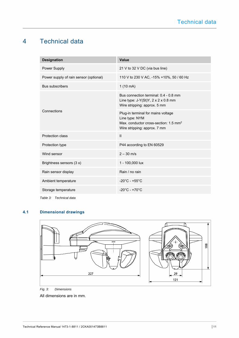
Fig. 3: Dimensions
All dimensions are in mm. Pos: 53 /Systemmodule/++++++++++++++ Seitenumbruch +++++++++++++++ @ 41\mod_1422789416992_0.docx @ 333487 @ @ 1
Connection, installation / mounting
Technical Reference Manual 1473-1-8811 / 2CKA001473B8811 │12
Pos: 55 /DinA-4 -- Online/1 Überschrift/Anschluss, Einbau / Montage @ 39\mod_1416583463978_15.docx @ 306808 @ 1 @ 1
5 Connection, installation / mounting
Pos: 56 /DinA-4 -- Online/1.1 Überschrift/Planungshinweise @ 44\mod_1443787679530_15.docx @ 395773 @ 2 @ 1
5.1 Planning instructions Pos: 57 /DinA-4 -- Online/11_Hinweise -- generell/Hinweis -- Planungshinweis @ 44\mod_1443788808213_15.docx @ 395807 @ @ 1
NOTE Planning and application instructions for the system are available in system manual for ABB-free@home®. This can be downloaded via www.abb.com/freeathome.
Pos: 58 /Systemmodule/- - - - - - Abstand - - - - - - @ 41\mod_1422791984802_0.docx @ 333519 @ @ 1
Pos: 59 /DinA-4 -- Online/1.1 Überschrift/Sicherheitshinweise @ 41\mod_1422793473426_15.docx @ 333552 @ 2 @ 1
5.2 Safety instructions Pos: 60 /DinA-4 -- Online/11_Sicherheitshinweise/Gefahr/Gefahr -- Stromschlag durch Kurzschluss @ 44\mod_1443788324915_15.docx @ 395790 @ @ 1
Danger - Electric shock due to short-circuit! Risk of death due to electrical voltage of 230 V during short-circuit in the low-voltage line. – Low-voltage and 230 V cables must not be installed together in a flush-
mounted socket! – Observe the spatial division during installation (> 10 mm) of SELV electric
circuits to other electric circuits. – If the minimum distance is insufficient, use electronic boxes and insulating
tubes. – Observe the correct polarity. – Observe the relevant standards.
Pos: 61 /DinA-4 -- Online/11_Sicherheitshinweise/Gefahr/Gefahr -- Fachkenntnisse mit Polarität @ 43\mod_1438603412838_15.docx @ 371243 @ @ 1
Danger - Electric voltage! Install the device only if you have the necessary electrical engineering knowledge and experience. ■ Incorrect installation endangers your life and that of the users of the
electrical system. ■ Incorrect installation can cause serious damage to property, e.g. due to fire. The minimum necessary expert knowledge and requirements for the installation are as follows: ■ Apply the "five safety rules" (DIN VDE 0105, EN 50110):
1. Disconnect 2. Secure against being re-connected 3. Ensure there is no voltage 4. Connect to earth and short-circuit 5. Cover or barricade adjacent live parts.
■ Use suitable personal protective clothing. ■ Use only suitable tools and measuring devices. ■ Check the type of supply network (TN system, IT system, TT system) to
secure the following power supply conditions (classic connection to ground, protective earthing, necessary additional measures, etc.).
■ Observe the correct polarity.
Pos: 62 /Systemmodule/++++++++++++++ Seitenumbruch +++++++++++++++ @ 41\mod_1422789416992_0.docx @ 333487 @ @ 1
Connection, installation / mounting
Technical Reference Manual 1473-1-8811 / 2CKA001473B8811 │13
Pos: 63 /DinA-4 -- Online/1.1 Überschrift/Anschlussbilder @ 43\mod_1435299880957_15.docx @ 368926 @ 2 @ 1
5.3 Circuit diagrams Pos: 64 /DinA-4 -- Online/Anschluss, Einbau / Montage/Elektrischer Anschluss/Anschlussbilder/Anschlussbild -- 6228 / WS-1 @ 44\mod_1443787248900_15.docx @ 395756 @ @ 1
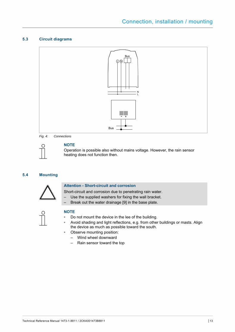
Fig. 4: Connections
NOTE Operation is possible also without mains voltage. However, the rain sensor heating does not function then.
Pos: 65 /DinA-4 -- Online/1.1 Überschrift/Montage @ 41\mod_1422622341647_15.docx @ 332296 @ 2 @ 1
5.4 Mounting Pos: 66 /DinA-4 -- Online/11_Sicherheitshinweise/Achtung/Achtung -- Kurzschluss und Korrosion -- 6228 / WS-1 @ 44\mod_1443789149092_15.docx @ 395824 @ @ 1
Attention - Short-circuit and corrosion Short-circuit and corrosion due to penetrating rain water. – Use the supplied washers for fixing the wall bracket. – Break out the water drainage [9] in the base plate.
Pos: 67 /DinA-4 -- Online/Anschluss, Einbau / Montage/Einbau / Montage/Montage in UP- / AP-Dosen/Montage/Montage -- 6228 / WS-1 @ 44\mod_1443791372313_15.docx @ 395858 @ @ 1
NOTE ■ Do not mount the device in the lee of the building. ■ Avoid shading and light reflections, e.g. from other buildings or masts. Align
the device as much as possible toward the south. ■ Observe mounting position:
– Wind wheel downward – Rain sensor toward the top
Connection, installation / mounting
Technical Reference Manual 1473-1-8811 / 2CKA001473B8811 │14
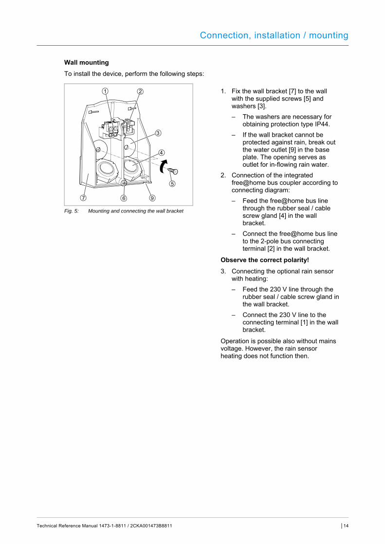
Wall mounting To install the device, perform the following steps:
1. Fix the wall bracket [7] to the wall with the supplied screws [5] and washers [3]. – The washers are necessary for
obtaining protection type IP44. – If the wall bracket cannot be
protected against rain, break out the water outlet [9] in the base plate. The opening serves as outlet for in-flowing rain water.
2. Connection of the integrated free@home bus coupler according to connecting diagram: – Feed the free@home bus line
through the rubber seal / cable screw gland [4] in the wall bracket.
– Connect the free@home bus line to the 2-pole bus connecting terminal [2] in the wall bracket.
Observe the correct polarity! 3. Connecting the optional rain sensor
with heating: – Feed the 230 V line through the
rubber seal / cable screw gland in the wall bracket.
– Connect the 230 V line to the connecting terminal [1] in the wall bracket.
Operation is possible also without mains voltage. However, the rain sensor heating does not function then.
Fig. 5: Mounting and connecting the wall bracket
Connection, installation / mounting
Technical Reference Manual 1473-1-8811 / 2CKA001473B8811 │15
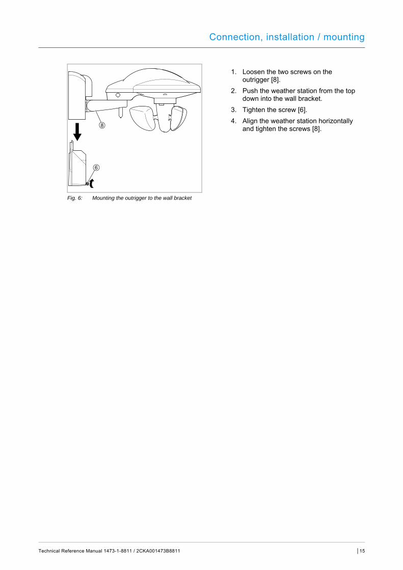
1. Loosen the two screws on the outrigger [8].
2. Push the weather station from the top down into the wall bracket.
3. Tighten the screw [6]. 4. Align the weather station horizontally
and tighten the screws [8].
Fig. 6: Mounting the outrigger to the wall bracket
Pos: 68 /Systemmodule/++++++++++++++ Seitenumbruch +++++++++++++++ @ 41\mod_1422789416992_0.docx @ 333487 @ @ 1

Commissioning
Technical Reference Manual 1473-1-8811 / 2CKA001473B8811 │16
Pos: 70 /DinA-4 -- Online/1 Überschrift/Inbetriebnahme @ 39\mod_1416583510249_15.docx @ 306823 @ 1 @ 1
6 Commissioning
Pos: 71 /DinA-4 -- Online/Inbetriebnahme/Inbetriebnahme -- Mechanisch/Einleitung/Einleitung -- System Access Point @ 44\mod_1443795712217_15.docx @ 395976 @ @ 1
Commissioning of the device is always carried out via the Web-based surface of the System Access Point. It is assumed that the basic commissioning steps of the overall system have already been carried out. Knowledge about the Web-based commissioning software of the System Access Point is assumed.
The System Access Point establishes the connection between the free@home participants and the smartphone, tablet or PC. The System Access Point is used to identify and program the participants during commissioning.
Devices which are physically connected to the free@home bus, log themselves automatically into the System Access Point. They transmit information about their type and supported functions (see chapter 3.3 “Functions“ on page 9).
During initial commissioning all devices are given a universal name, e.g. "Sensor/switch actuator 1/1gang". The installer must assign names that are practical and specific for the system, e.g. in "Living room ceiling light".
The devices must be parameterised for the use of additional functions.
Pos: 72 /DinA-4 -- Online/11_Sicherheitshinweise/Achtung/Achtung -- Windschäden -- 6228 / WS-1 @ 44\mod_1443777035762_15.docx @ 395513 @ @ 1
Attention Awnings and blinds need time to retract when it is windy. ■ The wind thresholds under the value specified by the manufacturer of the
awnings/blinds need to be parameterized.
Pos: 73 /DinA-4 -- Online/11_Hinweise -- generell/Hinweis -- Inbetriebnahme und Parametrierung @ 44\mod_1443795035286_15.docx @ 395875 @ @ 1
NOTE General information about commissioning and parameterization is available in the technical reference manual and the online Help of the System Access Point.
Pos: 74 /Systemmodule/- - - - - - Abstand - - - - - - @ 41\mod_1422791984802_0.docx @ 333519 @ @ 1
Pos: 75 /DinA-4 -- Online/1.1 Überschrift/Gerätezuordnung und Kanalfestlegung @ 44\mod_1443799895682_15.docx @ 396029 @ 2 @ 1
6.1 Allocation of devices and definition of channels Pos: 76 /DinA-4 -- Online/Inbetriebnahme/Inbetriebnahme -- Mechanisch/Gerät hinzufügen/freeAThome/Gerätezuordnung @ 44\mod_1445851139034_15.docx @ 401499 @ @ 1
The devices connected to the system must be identified, i.e. they are allocated to a room according to their function and are given a practical name.
The allocation is made via the allocation function of the Web-based user interface of the System Access Point.
Pos: 77 /Systemmodule/++++++++++++++ Seitenumbruch +++++++++++++++ @ 41\mod_1422789416992_0.docx @ 333487 @ @ 1

Commissioning
Technical Reference Manual 1473-1-8811 / 2CKA001473B8811 │17
Pos: 78 /DinA-4 -- Online/1.1.1 Überschrift/Gerät hinzufügen @ 44\mod_1443800235294_15.docx @ 396046 @ 3 @ 1
6.1.1 Add device Pos: 79 /DinA-4 -- Online/Inbetriebnahme/Inbetriebnahme -- Mechanisch/Gerät hinzufügen/freeAThome/Gerät hinzufügen -- 6228 @ 44\mod_1444029202186_15.docx @ 396170 @ @ 1
Fig. 7: Selecting the device group
1. Select the correct device group in the "Add device" bar.
NOTE Ensure that the correct filter is set, so that the correct device group is displayed.
Fig. 8: Add device
2. In the "Add device" bar select the desired application and pull the icon via drag-and-drop onto the floor plan in the working area.
Commissioning
Technical Reference Manual 1473-1-8811 / 2CKA001473B8811 │18
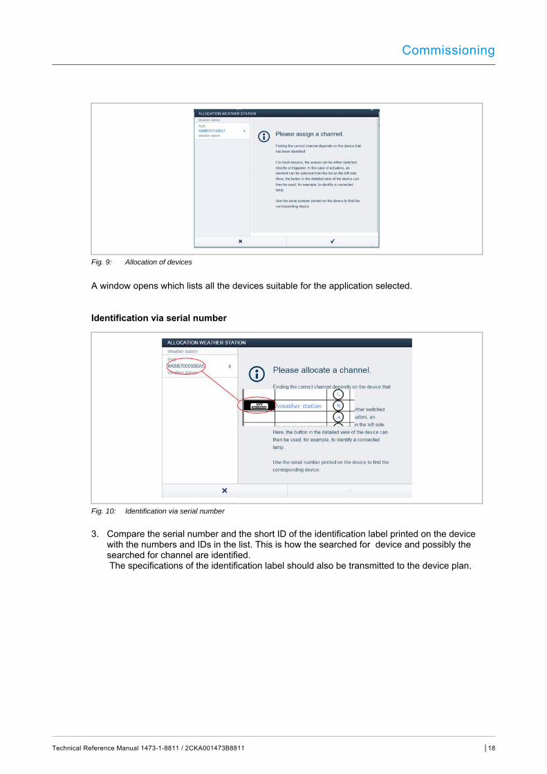
Fig. 9: Allocation of devices
A window opens which lists all the devices suitable for the application selected.
Identification via serial number
Fig. 10: Identification via serial number
3. Compare the serial number and the short ID of the identification label printed on the device with the numbers and IDs in the list. This is how the searched for device and possibly the searched for channel are identified. The specifications of the identification label should also be transmitted to the device plan.
Commissioning
Technical Reference Manual 1473-1-8811 / 2CKA001473B8811 │19
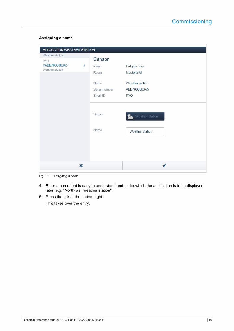
Assigning a name
Fig. 11: Assigning a name
4. Enter a name that is easy to understand and under which the application is to be displayed later, e.g. "North-wall weather station".
5. Press the tick at the bottom right. This takes over the entry.
Pos: 80 /Systemmodule/++++++++++++++ Seitenumbruch +++++++++++++++ @ 41\mod_1422789416992_0.docx @ 333487 @ @ 1

Commissioning
Technical Reference Manual 1473-1-8811 / 2CKA001473B8811 │20
Pos: 81 /DinA-4 -- Online/1.1 Überschrift/Einstellmöglichkeiten pro Kanal @ 44\mod_1443800430356_15.docx @ 396063 @ 2 @ 1
6.2 Setting options per channel Pos: 82 /DinA-4 -- Online/Inbetriebnahme/Inbetriebnahme -- Mechanisch/Gerät hinzufügen/freeAThome/Einstellmöglichkeiten pro Kanal -- 6228 @ 44\mod_1448987225261_15.docx @ 405431 @ @ 1
General settings and special parameter settings must be made for each channel.
The settings are made via the allocation function of the Web-based user interface of the System Access Point.
Pos: 83 /DinA-4 -- Online/Inbetriebnahme/Inbetriebnahme -- Mechanisch/Gerät hinzufügen/freeAThome/Gerät wählen -- 6228 @ 44\mod_1444030821164_15.docx @ 396204 @ @ 1
Select unit
Fig. 12: Select device
1. Select the device icon [1] in the floor plan of the working area view.
All setting options for the respective channel are displayed in the list view [2].
The settings in the following section are available.
Pos: 84 /Systemmodule/++++++++++++++ Seitenumbruch +++++++++++++++ @ 41\mod_1422789416992_0.docx @ 333487 @ @ 1

Commissioning
Technical Reference Manual 1473-1-8811 / 2CKA001473B8811 │21
Pos: 85 /DinA-4 -- Online/1.1.1 Überschrift/Wetterstation einstellen @ 44\mod_1443800553316_15.docx @ 396080 @ 3 @ 1
6.2.1 Setting the weather station Pos: 86 /DinA-4 -- Online/Inbetriebnahme/Inbetriebnahme -- Mechanisch/Gerät hinzufügen/freeAThome/Einstellungen -- 6228 @ 44\mod_1444031349150_15.docx @ 396221 @ @ 1
General sensor settings
[1] Changing the name [2] Deleting the channel [3] Specifying the transmission interval [4] Selection of the individual sensors
Fig. 13: General sensor settings
Setting the brightness sensor
[1] Setting the lux value which is to activate the brightness alarm
Fig. 14: Setting the brightness sensor
For example:
The brightness sensor is connected to a blind actuator: ■ The brightness value is exceeded: the blind is moved down
(delay time: 5 minutes) ■ The brightness value drops below setpoint: the blind is moved up
(delay time: 15 minutes)
The hysteresis is generally set on 5000 lux.

Commissioning
Technical Reference Manual 1473-1-8811 / 2CKA001473B8811 │22
Setting the temperature sensor
[1] Setting the ambient temperature which activates the frost alarm.
Fig. 15: Setting the temperature sensor
For example:
The temperature sensor is connected to a blind actuator: ■ The frost protection temperature is exceeded: the blind is moved down
(delay time: 5 minutes) ■ The frost protection temperature drops below setpoint: the blind is moved up
(delay time: 15 minutes)
Setting the wind sensor
[1] Setting the wind force which activates the wind alarm.
Fig. 16: Setting the wind sensor
For example:
The wind sensor is connected to a blind actuator: ■ The wind alarm is exceeded: the blind is moved up
(delay time: none) ■ The wind alarm drops below setpoint: the blind is moved down
(delay time: 10 minutes)

Commissioning
Technical Reference Manual 1473-1-8811 / 2CKA001473B8811 │23
Rain sensor
1. Setting the sensitivity of the rain sensor. – With setting "High" the sensor is more
sensitive. This should be used in areas with very little rain.
– Setting "Low" should be used in areas with a lot of rain.
Fig. 17: >>Designation of graphics<<
For example:
The rain sensor is connected to a blind actuator: ■ The rain alarm is exceeded: the blind is moved down
(delay time: none) ■ The rain alarm drops below setpoint: the blind is moved up
(delay time: 10 minutes)
Pos: 87 /DinA-4 -- Online/1.1 Überschrift/Verknüpfungen @ 44\mod_1443800757566_15.docx @ 396097 @ 2 @ 1
6.3 Links Pos: 88 /DinA-4 -- Online/Inbetriebnahme/Inbetriebnahme -- Mechanisch/Gerät hinzufügen/freeAThome/Verknüpfungen vornehmen -- 6228 @ 44\mod_1444032818264_15.docx @ 396238 @ @ 1
The weather stations and actuators created via the allocation function can now be linked with each other. This links the individual sensors of the weather station with one or several corresponding actuators. For example, the wind sensor can be linked with blind actuators. This causes the blinds to be moved up when the set wind force is reached.
The linking in the list view is made via the linking function of the Web-based user interface of the System Access Point.
Pos: 89 /Systemmodule/++++++++++++++ Seitenumbruch +++++++++++++++ @ 41\mod_1422789416992_0.docx @ 333487 @ @ 1

Commissioning
Technical Reference Manual 1473-1-8811 / 2CKA001473B8811 │24
Pos: 90 /DinA-4 -- Online/1.1.1 Überschrift/Aktor und Sensor verknüpfen @ 44\mod_1443801051252_15.docx @ 396114 @ 2 @ 1
6.3.1 Linking actuator and sensor Pos: 91 /DinA-4 -- Online/Inbetriebnahme/Inbetriebnahme -- Mechanisch/Gerät hinzufügen/freeAThome/Aktor und Sensor verknüpfen -- 6228 @ 44\mod_1444032987236_15.docx @ 396255 @ @ 1
Fig. 18: Linking actuator and sensor
1. On the working area select the sensor [1] that is to be linked with the actuator. Now a selection list opens next to the icon of the weather station. Here all sensors of the weather station are listed.
2. Select a sensor. The corresponding sensor is displayed in the list view. 3. Select the actuator [2] that is to be served by the sensor. 4. Press the arrow [3] at the bottom right to take over the entries.
A blue connecting line indicates the link between the two devices. The configuration is now transmitted automatically to the devices. The transmission can, depending on the number of affected devices, take a number of seconds. During the transmission a progress bar is displayed around the devices affected.
NOTE A sensor can be linked with several actuators. A sensor can additionally be linked with scenes.
Pos: 92 /Systemmodule/++++++++++++++ Seitenumbruch +++++++++++++++ @ 41\mod_1422789416992_0.docx @ 333487 @ @ 1

Update
Technical Reference Manual 1473-1-8811 / 2CKA001473B8811 │25
Pos: 94 /DinA-4 -- Online/1 Überschrift/Update @ 45\mod_1452181198619_15.docx @ 427123 @ 1 @ 1
7 Update
Pos: 95 /DinA-4 -- Online/Updatemöglichkeiten/Software-Aktualisierung -- System Access Point @ 44\mod_1443799609297_15.docx @ 396012 @ @ 1
A firmware update is carried out via the Web-based user interface of the System Access Point.
Pos: 97 /DinA-4 -- Online/1 Überschrift/Bedienung @ 39\mod_1416583691883_15.docx @ 306853 @ 1 @ 1
8 Operation
Pos: 98 /DinA-4 -- Online/Bedienung/Betrieb -- Normalbetrieb / Bedienung Alltagsbetrieb/01_Einleitung/freeAThome/Einleitung -- 6228 / WS-1 @ 44\mod_1445945739652_15.docx @ 402025 @ @ 1
The device responds automatically to various types of weather. No action is therefore required on the part of the user.
Pos: 100 /DinA-4 -- Online/1 Überschrift/Wartung @ 39\mod_1416583885655_15.docx @ 306868 @ 1 @ 1
9 Maintenance
Pos: 101 /DinA-4 -- Online/Wartung/Wartungsfreies Gerät @ 43\mod_1438692990565_15.docx @ 371941 @ @ 1
The device is maintenance-free. In case of damage, e.g. during transport or storage), do not perform repairs. Once the device is opened, the warranty is void.
Access to the device must be guaranteed for operation, testing, inspection, maintenance and repairs (according to DIN VDE 0100-520).
Pos: 102 /DinA-4 -- Online/Wartung/Reinigung/Weiches Tuch und Seifenlösung @ 42\mod_1424596333950_15.docx @ 336596 @ @ 1
Clean dirty devices with a soft dry cloth.
– If this is insufficient, the cloth can be moistened slightly with a soap solution.
Pos: 103 /Systemmodule/++++++++++++++ Seitenumbruch +++++++++++++++ @ 41\mod_1422789416992_0.docx @ 333487 @ @ 1
Notes
Technical Reference Manual 1473-1-8811 / 2CKA001473B8811 │26
Pos: 105 /DinA-4 -- Online/1 Überschrift/Notizen @ 39\mod_1416584224978_15.docx @ 306928 @ 1 @ 1
10 Notes
Pos: 106 /Systemmodule/++++++++++++++ Seitenumbruch +++++++++++++++ @ 41\mod_1422789416992_0.docx @ 333487 @ @ 1

Index
Technical Reference Manual 1473-1-8811 / 2CKA001473B8811 │27
Pos: 108 /DinA-4 -- Online/1 Überschrift/Index @ 42\mod_1424701000643_15.docx @ 337966 @ 1 @ 1
11 Index
Pos: 109 /DinA-4 -- Online/Index/Index @ 42\mod_1424701092528_15.docx @ 337984 @ @ 1
A Add device ........................................................................... 17 Allocation of devices ............................................................ 16 Ambient temperature ........................................................... 11 Assigning a name ................................................................ 19
B Brightness sensor ............................................................ 8, 11 Bus connection .................................................................... 10 Buttons .................................................................................. 8
C Circuit diagrams ................................................................... 13 Commissioning .................................................................... 16 Connection, installation / mounting ...................................... 12 Connections ......................................................................... 11
D Device overview .................................................................. 10 Dimensional drawings ......................................................... 11
E Environment .......................................................................... 7
F Firmware update .................................................................. 25 Functions ......................................................................... 9, 16
G General sensor settings ....................................................... 21
I Identification ........................................................................ 18 Identification label ................................................................ 18 Improper use ......................................................................... 5 Information and symbols used ............................................... 4 Initial commissioning ........................................................... 16 Intended use .......................................................................... 5
L LED ........................................................................................ 8 Leeward side ....................................................................... 13 Links .................................................................................... 23
actuator ........................................................................... 24 sensor ............................................................................. 24
M Mains supply ........................................................................ 10
Maintenance ........................................................................25 Mounting ..............................................................................13
N Notes ....................................................................................26 Notes on the instruction manual ............................................3
O Operation .............................................................................25 Overview of types ..................................................................9
P Planning instructions ............................................................12 Power Supply .......................................................................11 Protection class ....................................................................11 Protection type .....................................................................11
Q Qualification of personnel ......................................................5
R Rain sensor ............................................................................8 Rain water outlet ..................................................................10
S Safety .....................................................................................4 Safety instructions ............................................................6, 12 Scope of supply .....................................................................9 Select unit ............................................................................20 Serial number .......................................................................18 Setting the brightness sensor ..............................................21 Setting the wind sensor ........................................................22 Setup and function .................................................................8 Storage temperature ............................................................11 System Access Point ...........................................................16
T Target group ..........................................................................5 Technical data ......................................................................11 Temperature sensor ...............................................................8
U Update .................................................................................25
W Wall bracket .........................................................................10 Wind sensor .........................................................................11 Wind wheel ............................................................................8
=== Ende der Liste für Textmarke Inhalt ===

Pos: 111 /DinA-4 -- Online/00_Rueckseite/Rueckseite -- BJE/ABB @ 39\mod_1415285579815_15.docx @ 305612 @ @ 1
A member of the ABB Group Busch-Jaeger Elektro GmbH PO box 58505 Lüdenscheid Freisenbergstraße 2 58513 Lüdenscheid www.BUSCH-JAEGER.com [email protected] Central sales service: Tel.: +49 2351 956-1600 Fax: +49 2351 956-1700
Notice We reserve the right to make technical changes at all times as well as changes to the contents of this document without prior notice. The detailed specifications agreed upon apply for orders. ABB accepts no responsibility for possible errors or incompleteness in this document. We reserve all rights to this document and the topics and illustrations contained therein. The document and its contents, or extracts thereof, must not be reproduced, transmitted or reused by third parties without prior written consent by ABB Copyright© 2016 Busch-Jaeger Elektro GmbH All rights reserved
Tech
nica
l Ref
eren
ce M
anua
l 14
73-1
-881
1 / 2
CK
A00
1473
B88
11
=== Ende der Liste für Textmarke Rueckseite ===