Embed Size (px)
Citation preview
Describes how to control the printer and necessary informationwhen you develop applications.
Describes setup and installation of the product and peripherals.
Describes how to handle the product.
Describes features and general specifications for the product.
Technical Reference Guide
Describes interfaces, connectors and character code tables.
M00017501
Rev. B
Product Overview
Setup
Application Development Information
Handling
Appendix

2
Cautions• No part of this document may be reproduced, stored in a retrieval system, or transmitted in any form
or by any means, electronic, mechanical, photocopying, recording, or otherwise, without the prior
written permission of Seiko Epson Corporation.
• The contents of this document are subject to change without notice. Please contact us for the latest
information.
• While every precaution has taken in the preparation of this document, Seiko Epson Corporation
assumes no responsibility for errors or omissions.
• Neither is any liability assumed for damages resulting from the use of the information contained
herein.
• Neither Seiko Epson Corporation nor its affiliates shall be liable to the purchaser of this product or third
parties for damages, losses, costs, or expenses incurred by the purchaser or third parties as a result of:
accident, misuse, or abuse of this product or unauthorized modifications, repairs, or alterations to this
product, or (excluding the U.S.) failure to strictly comply with Seiko Epson Corporation’s operating
and maintenance instructions.
• Seiko Epson Corporation shall not be liable against any damages or problems arising from the use of
any options or any consumable products other than those designated as Original EPSON Products or
EPSON Approved Products by Seiko Epson Corporation.
TrademarksEPSON and ESC/POS are registered trademarks of Seiko Epson Corporation in Japan and other
countries/regions.
Microsoft and Windows are registered trademarks of Microsoft Corporation.
ESC/POS® Command SystemEPSON has been taking industry’s initiatives with its own POS printer command system (ESC/POS).
ESC/POS has a large number of commands including patented ones. Its high scalability enables users
to build versatile POS systems. The system is compatible with all types of EPSON POS printers (excluding
the TM-C100) and displays. Moreover, its flexibility makes it easy to upgrade the future. The functionality
and the user-friendliness is valued around the world.
3
Revision History
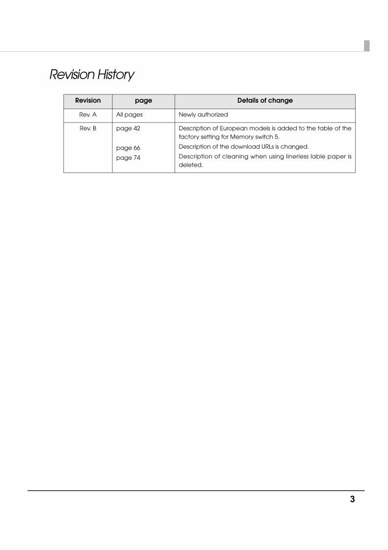
Revision page Details of change
Rev. A All pages Newly authorized
Rev. B page 42
page 66
page 74
Description of European models is added to the table of the factory setting for Memory switch 5.
Description of the download URLs is changed.
Description of cleaning when using linerless lable paper is deleted.

4
For Safety
Key to Symbols
The symbols in this manual are identified by their level of importance, as defined below. Read the following carefully before handling the product.
WARNING
You must follow warnings carefully to avoid serious bodily injury.
CAUTION
Provides information that must be observed to prevent damage to the equipment or loss of data.• Possibility of sustaining physical injuries.• Possibility of causing physical damage.• Possibility of causing information loss.
Provides information that must be observed to avoid damage to your equipment or a malfunction.
Provides important information and useful tips.

5
Warnings
WARNING
• To avoid risk of electric shock, do not set up this product or handle cables during a thunderstorm
• Never insert or disconnect the power plug with wet hands. Doing so may result in severe shock.
• Handle the power cable with care. Improper handling may lead to fire or electric shock.∗ Do not modify or attempt to repair the cable.∗ Do not place any heavy object on top of the cable.∗ Avoid excessive bending, twisting, and pulling.∗ Do not place the cable near heating equipment.∗ Check that the plug is clean before plugging it in.∗ Be sure to push the plug all the way in.
• Be sure to use the specified power source. Connection to an improper power source may cause fire or shock.
• Do not place multiple loads on the power outlet. Overloading the outlet may lead to fire.
• Shut down your equipment immediately if it produces smoke, a strange odor, or unusual noise. Continued use may lead to fire. Immediately unplug the equipment and contact your dealer or a Seiko Epson service center for advice.
• Never attempt to repair this product yourself. Improper repair work can be dangerous.
• Never disassemble or modify this product. Tampering with this product may result in injury or fire.
• Do not allow foreign matter to fall into the equipment. Penetration by foreign objects may lead to fire.
• If water or other liquid spills into this equipment, do not continue to use it. Continued use may lead to fire. Unplug the power cord immediately and contact your dealer or a Seiko Epson service center for advice.
• If you open the DIP switch cover, be sure to close the cover and tighten the screw after adjusting the DIP switch. Using this product with the cover open may cause fire or electric shock.
6
Cautions
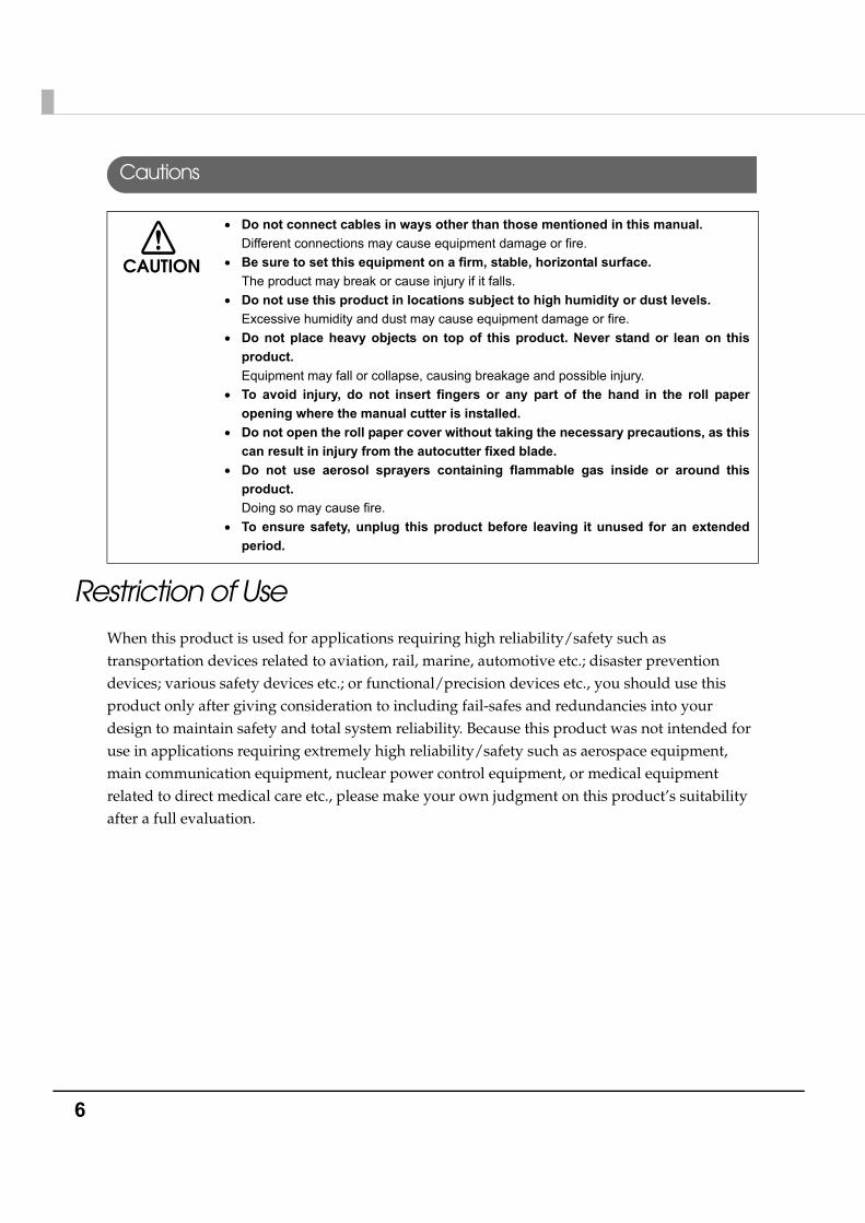
Restriction of UseWhen this product is used for applications requiring high reliability/safety such as transportation devices related to aviation, rail, marine, automotive etc.; disaster prevention devices; various safety devices etc.; or functional/precision devices etc., you should use this product only after giving consideration to including fail-safes and redundancies into your design to maintain safety and total system reliability. Because this product was not intended for use in applications requiring extremely high reliability/safety such as aerospace equipment, main communication equipment, nuclear power control equipment, or medical equipment related to direct medical care etc., please make your own judgment on this product’s suitability after a full evaluation.
CAUTION
• Do not connect cables in ways other than those mentioned in this manual. Different connections may cause equipment damage or fire.
• Be sure to set this equipment on a firm, stable, horizontal surface. The product may break or cause injury if it falls.
• Do not use this product in locations subject to high humidity or dust levels. Excessive humidity and dust may cause equipment damage or fire.
• Do not place heavy objects on top of this product. Never stand or lean on this product. Equipment may fall or collapse, causing breakage and possible injury.
• To avoid injury, do not insert fingers or any part of the hand in the roll paper opening where the manual cutter is installed.
• Do not open the roll paper cover without taking the necessary precautions, as this can result in injury from the autocutter fixed blade.
• Do not use aerosol sprayers containing flammable gas inside or around this product. Doing so may cause fire.
• To ensure safety, unplug this product before leaving it unused for an extended period.
7
About this Manual
Aim of the Manual
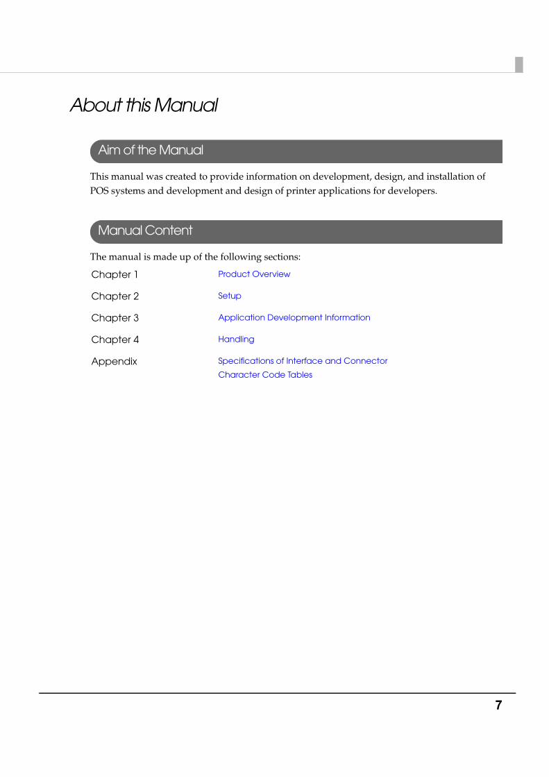
This manual was created to provide information on development, design, and installation of POS systems and development and design of printer applications for developers.
Manual Content
The manual is made up of the following sections:
Chapter 1 Product Overview
Chapter 2 Setup
Chapter 3 Application Development Information
Chapter 4 Handling
Appendix Specifications of Interface and Connector
Character Code Tables
8
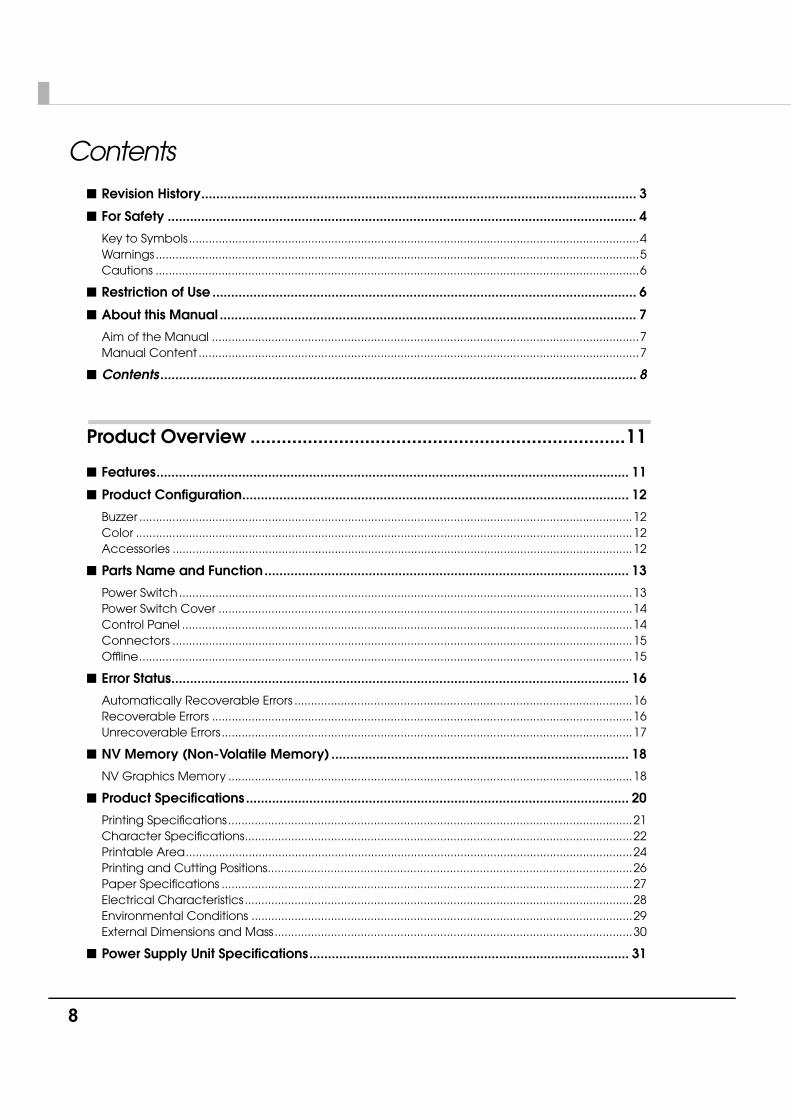
Contents■ Revision History..................................................................................................................... 3
■ For Safety .............................................................................................................................. 4
Key to Symbols........................................................................................................................................4Warnings..................................................................................................................................................5Cautions ..................................................................................................................................................6
■ Restriction of Use .................................................................................................................. 6
■ About this Manual ................................................................................................................ 7
Aim of the Manual .................................................................................................................................7Manual Content .....................................................................................................................................7
■ Contents................................................................................................................................ 8
Product Overview ........................................................................11
■ Features............................................................................................................................... 11
■ Product Configuration........................................................................................................ 12
Buzzer .....................................................................................................................................................12Color ......................................................................................................................................................12Accessories ...........................................................................................................................................12
■ Parts Name and Function.................................................................................................. 13
Power Switch.........................................................................................................................................13Power Switch Cover .............................................................................................................................14Control Panel ........................................................................................................................................14Connectors ...........................................................................................................................................15Offline.....................................................................................................................................................15
■ Error Status........................................................................................................................... 16
Automatically Recoverable Errors ......................................................................................................16Recoverable Errors ...............................................................................................................................16Unrecoverable Errors ............................................................................................................................17
■ NV Memory (Non-Volatile Memory) ................................................................................ 18
NV Graphics Memory ..........................................................................................................................18
■ Product Specifications....................................................................................................... 20
Printing Specifications..........................................................................................................................21Character Specifications.....................................................................................................................22Printable Area.......................................................................................................................................24Printing and Cutting Positions..............................................................................................................26Paper Specifications ............................................................................................................................27Electrical Characteristics.....................................................................................................................28Environmental Conditions ...................................................................................................................29External Dimensions and Mass............................................................................................................30
■ Power Supply Unit Specifications...................................................................................... 31
9
Power Supply Unit (PS-180).................................................................................................................. 31
Setup .............................................................................................33
■ Flow of Setup.......................................................................................................................33
■ Installing the Printer ............................................................................................................34
Important Notes on Horizontal Installation ....................................................................................... 34Important Notes on Wall Hanging ..................................................................................................... 34
■ Setting the DIP Switches .....................................................................................................35
Setting Procedure................................................................................................................................ 35For Serial Interface............................................................................................................................... 36For Parallel Interface/LAN/wireless LAN Interface............................................................................ 38For USB Interface.................................................................................................................................. 39Selecting the Print Density (DIP Switch 2-3/2-4)................................................................................ 40Selecting the BUSY Status.................................................................................................................... 41
■ Setting the Memory Switches ............................................................................................42
■ Adjusting the Near-End Sensor for Thermal Roll Paper ...................................................44
■ Connecting the Printer to the Host Computer .................................................................46
For Serial Interface............................................................................................................................... 46For Parallel Interface............................................................................................................................ 48For USB Interface.................................................................................................................................. 49For LAN Interface ................................................................................................................................. 51For Wireless LAN Interface................................................................................................................... 53
■ Connecting the Power Supply Unit (PS-180) ....................................................................54
Connecting the Power Supply Unit.................................................................................................... 54
■ Connecting the Cash Drawer............................................................................................55
Connecting the Drawer Kick-out Cable ........................................................................................... 55Setting the Buzzer................................................................................................................................. 56
Application Development Information......................................57
■ How to Control the Printer ..................................................................................................57
Selecting a Driver................................................................................................................................. 57Precautions on Using a Driver............................................................................................................. 58ESC/POS Command............................................................................................................................ 61
■ Software and Manuals .......................................................................................................65
Download............................................................................................................................................. 66
■ Setting Check Modes.........................................................................................................67
Self-test Mode ...................................................................................................................................... 67Hexadecimal Dumping Mode ........................................................................................................... 68
10
Handling .......................................................................................69
■ Installing and Replacing Roll Paper ................................................................................. 69
■ Attaching/Removing the Connector Cover .................................................................... 71
Attaching the Connector Cover ........................................................................................................71Removing the Connector Cover........................................................................................................71
■ Removing Jammed Paper ................................................................................................ 72
When the Roll Paper Cover Cannot be Opened.............................................................................72
■ Cleaning the Thermal Head.............................................................................................. 74
■ Preparing for Transport....................................................................................................... 74
Appendix......................................................................................75
■ Specifications of Interface and Connector ..................................................................... 75
RS-232C Serial Interface.......................................................................................................................75IEEE 1284 Parallel Interface..................................................................................................................78USB (Universal Serial Bus) Interface.....................................................................................................81
■ Character Code Tables ..................................................................................................... 82
Common to All Pages..........................................................................................................................82Page 0 [PC437: USA, Standard Europe].............................................................................................83Page 1 (Katakana)...............................................................................................................................84Page 2 (PC850: Multilingual) ...............................................................................................................85Page 3 (PC860: Portuguese) ...............................................................................................................86Page 4 (PC863: Canadian-French)....................................................................................................87Page 5 (PC865: Nordic) .......................................................................................................................88Page 16 (WPC1252) .............................................................................................................................89Page 17 (PC866: Cyrillic #2) ................................................................................................................90Page 18 (PC852: Latin2) ......................................................................................................................91Page 19 (PC858: Euro) .........................................................................................................................92Page 255 (User-Defined Page)............................................................................................................93International Character Sets...............................................................................................................94
Chapter 1 Product Overview
11
1
Product OverviewThis chapter describes features and specifications of the product.
FeaturesThe TM-T88IV for ReStick is a thermal printer that prints on the recommended liner-free label and the thermal paper, which has the same usability as the de facto standard receipt printer, TM-T88IV. The TM-T88IV for ReStick has the following features.
Printing• High-speed printing (When printing on the recommended liner-free label: 150 mm/s {5.9"/s}
maximum, When printing on thermal paper: 177 mm/s {6.97"/s} maximum), which enables issuing of batch receipts.
• Graphics are also printed with high-speed printing.
Handling• Easy drop-in paper loading
Software• Command protocol is based on the ESC/POS® Proprietary Command System.
• OPOS ADK and Windows® printer driver are available.
• In addition to supporting several kinds of bar code printing, two-dimensional code (PDF417, QR code) printing is possible when using the thermal roll paper.
• Various layouts are possible by using page mode.
• A maintenance counter function is supported.
Interface• Serial interface (RS-232C)
• Parallel interface (IEEE1284)
• USB interface (full-speed)
• Ethernet interface (10/100BASE-T)
• Wireless LAN interface (IEEE802.11b)
Various interface boards (EPSON UB series) can also be used.
12
Product Configuration
Buzzer
The buzzer function is available
Color
• ECW (Epson Cool White)
• EDG (Epson Dark Gray)
Accessories
Attachments• Roll paper (for operation check)• User’s manual• Power switch cover• Connector cover• Locking wire saddle (only for USB interface model)• External power supply (Model: PS-180) (for the model with the power supply unit)• AC cable for the PS-180 (for the model with the power supply unit)
Options• Power supply box (Model: BX88)• Affixing tapes for fixing the printer (Model: DF-10)• Wall hanging bracket (Model: WH-10)• Various interface boards (UB series)
Chapter 1 Product Overview
13
1
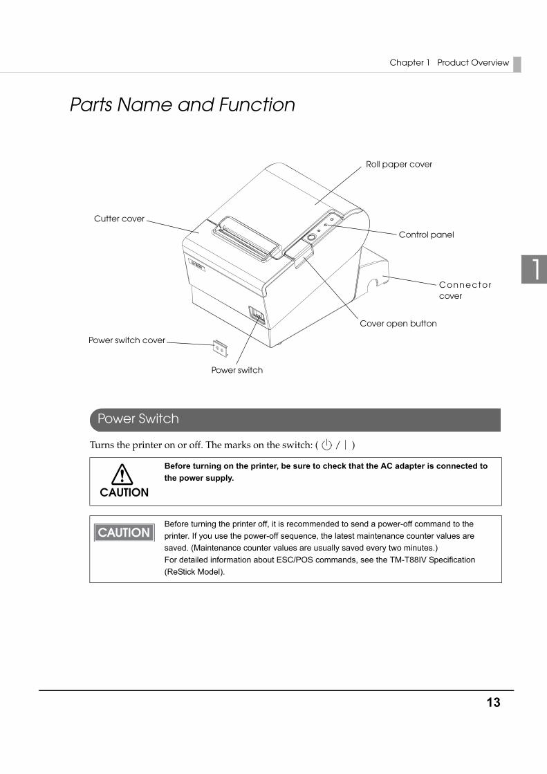
Parts Name and Function
Power Switch
Turns the printer on or off. The marks on the switch: ( / )
CAUTION
Before turning on the printer, be sure to check that the AC adapter is connected to the power supply.
Before turning the printer off, it is recommended to send a power-off command to the printer. If you use the power-off sequence, the latest maintenance counter values are saved. (Maintenance counter values are usually saved every two minutes.)For detailed information about ESC/POS commands, see the TM-T88IV Specification (ReStick Model).
Roll paper cover
Control panel
Cover open button
Power switch
Cutter cover
Power switch cover
Connector cover
14
Power Switch Cover
Install the power switch cover that comes with the TM-T88IV onto the printer to prevent inadvertent changing of the power switch, to prevent tampering, and to improve the appearance of the printer.
To reset the printer when the power switch cover is installed, insert a long, thin object (such as the end of a paper clip) into the hole in the power switch cover and press the power switch.
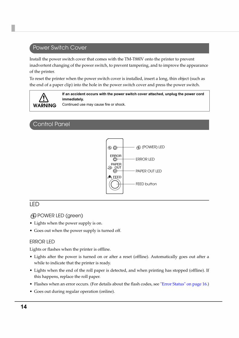
Control Panel
LED
POWER LED (green)
• Lights when the power supply is on.
• Goes out when the power supply is turned off.
ERROR LED
Lights or flashes when the printer is offline.
• Lights after the power is turned on or after a reset (offline). Automatically goes out after a while to indicate that the printer is ready.
• Lights when the end of the roll paper is detected, and when printing has stopped (offline). If this happens, replace the roll paper.
• Flashes when an error occurs. (For details about the flash codes, see "Error Status" on page 16.)
• Goes out during regular operation (online).
WARNING
If an accident occurs with the power switch cover attached, unplug the power cord immediately. Continued use may cause fire or shock.
(POWER) LED
ERROR LED
PAPER OUT LED
FEED button
Chapter 1 Product Overview
15
1
PAPER OUT LED
• Lights when there is no more roll paper. When you select to use the thermal roll paper by DIP switches, this LED lights also when there is little paper remaining.
• Off when there is a sufficient amount of roll paper remaining.
• Flashes when a self-test is in progress.
FEED buttonPressing this button once feeds the roll paper by one line. Holding this button down feeds the roll paper continuously.
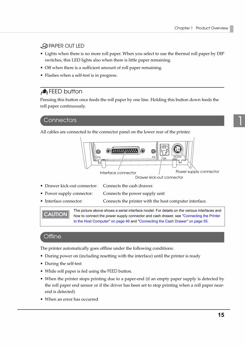
Connectors
All cables are connected to the connector panel on the lower rear of the printer.
• Drawer kick-out connector: Connects the cash drawer.
• Power supply connector: Connects the power supply unit
• Interface connector: Connects the printer with the host computer interface.
Offline
The printer automatically goes offline under the following conditions:
• During power on (including resetting with the interface) until the printer is ready
• During the self-test
• While roll paper is fed using the FEED button.
• When the printer stops printing due to a paper-end (if an empty paper supply is detected by the roll paper end sensor or if the driver has been set to stop printing when a roll paper near-end is detected)
• When an error has occurred
The picture above shows a serial interface model. For details on the various interfaces and how to connect the power supply connector and cash drawer, see "Connecting the Printer to the Host Computer" on page 46 and "Connecting the Cash Drawer" on page 55.
DKDC24VFGFG
Interface connectorDrawer kick-out connector
Power supply connector
16
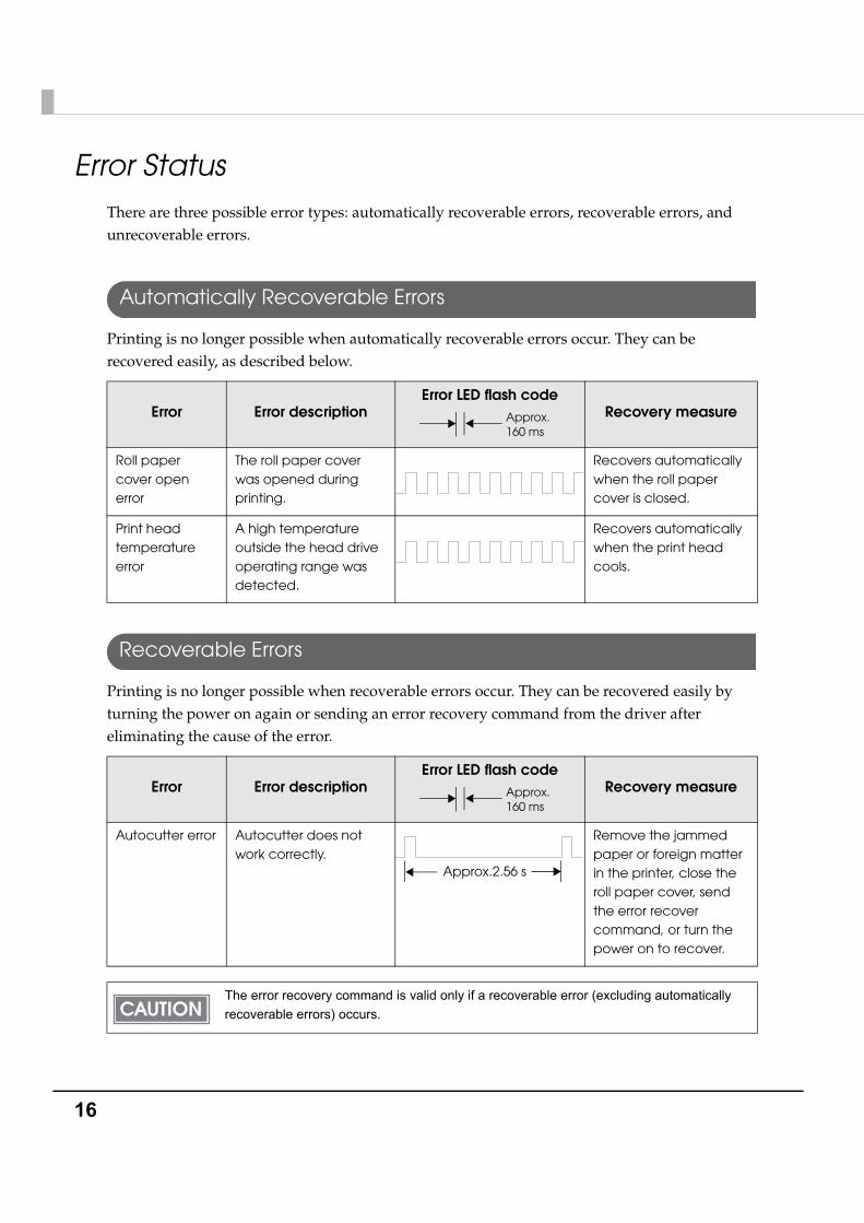
Error StatusThere are three possible error types: automatically recoverable errors, recoverable errors, and unrecoverable errors.
Automatically Recoverable Errors
Printing is no longer possible when automatically recoverable errors occur. They can be recovered easily, as described below.
Recoverable Errors
Printing is no longer possible when recoverable errors occur. They can be recovered easily by turning the power on again or sending an error recovery command from the driver after eliminating the cause of the error.
Error Error descriptionError LED flash code
Recovery measure
Roll paper cover open error
The roll paper cover was opened during printing.
Recovers automatically when the roll paper cover is closed.
Print head temperature error
A high temperature outside the head drive operating range was detected.
Recovers automatically when the print head cools.
Error Error descriptionError LED flash code
Recovery measure
Autocutter error Autocutter does not work correctly.
Remove the jammed paper or foreign matter in the printer, close the roll paper cover, send the error recover command, or turn the power on to recover.
The error recovery command is valid only if a recoverable error (excluding automatically recoverable errors) occurs.
Approx.160 ms
Approx.160 ms
Approx.2.56 s
Chapter 1 Product Overview
17
1
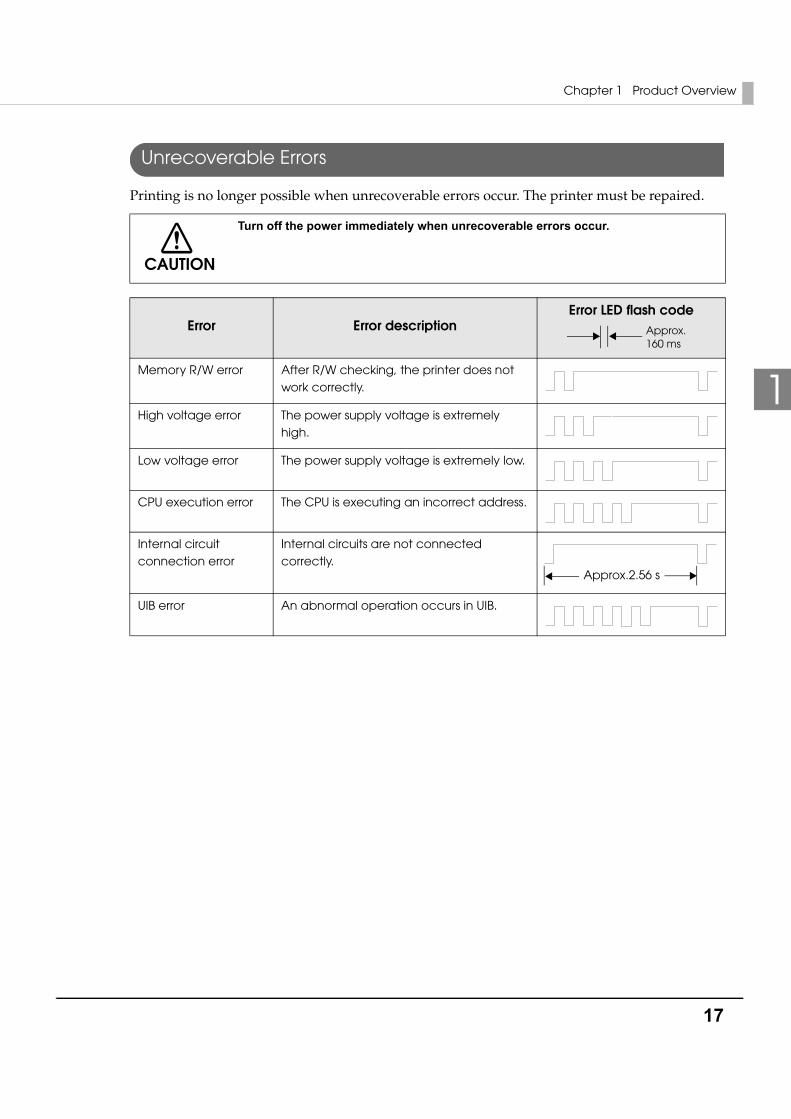
Unrecoverable Errors
Printing is no longer possible when unrecoverable errors occur. The printer must be repaired.
CAUTION
Turn off the power immediately when unrecoverable errors occur.
Error Error descriptionError LED flash code
Memory R/W error After R/W checking, the printer does not work correctly.
High voltage error The power supply voltage is extremely high.
Low voltage error The power supply voltage is extremely low.
CPU execution error The CPU is executing an incorrect address.
Internal circuit connection error
Internal circuits are not connected correctly.
UIB error An abnormal operation occurs in UIB.
Approx.160 ms
Approx.2.56 s
18
NV Memory (Non-Volatile Memory)The printer has NV memory which includes the user NV memory and NV graphics memory that users can use.
NV Graphics Memory
Graphics such as shop logos to be printed on receipts can be stored. Even with a serial interface model whose communication speed is low, high speed graphic printing is possible.
Use the TM Flash Logo Setup utility for NVRAM to register graphics.
NV Graphics Print ModeIn this mode the printer prints the following:
• Capacity of the NV graphics
• Used amount of the NV graphics
• Unused capacity of the NV graphics
• Number of the NV graphics that are registered
• Key code, number of dots in X direction, number of dots in Y direction, number of colors to be defined.
• NV graphics data
CAUTION
NV memory can be rewritten about 100,000 times. As a guide, NV memory rewriting should be 10 times or less a day when you program applications.
Chapter 1 Product Overview
19
1
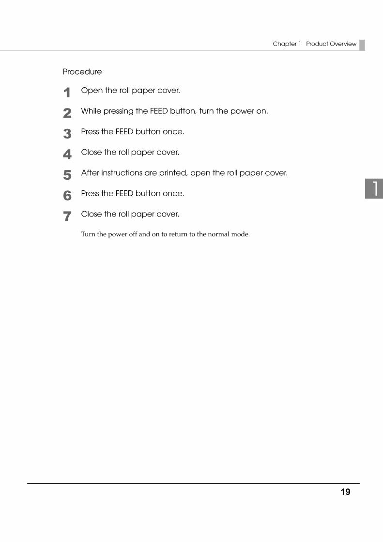
Procedure
1 Open the roll paper cover.
2 While pressing the FEED button, turn the power on.
3 Press the FEED button once.
4 Close the roll paper cover.
5 After instructions are printed, open the roll paper cover.
6 Press the FEED button once.
7 Close the roll paper cover.
Turn the power off and on to return to the normal mode.
20
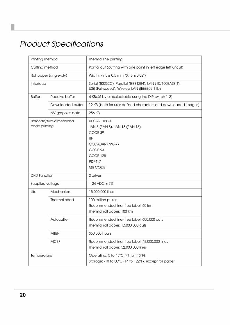
Product Specifications
Printing method Thermal line printing
Cutting method Partial cut (cutting with one point in left edge left uncut)
Roll paper (single-ply) Width: 79.5 ± 0.5 mm (3.13 ± 0.02")
Interface Serial (RS232C), Parallel (IEEE1284), LAN (10/100BASE-T), USB (Full-speed), Wireless LAN (IEEE802.11b)
Buffer Receive buffer 4 KB/45 bytes (selectable using the DIP switch 1-2)
Downloaded buffer 12 KB (both for user-defined characters and downloaded images)
NV graphics data 256 KB
Barcode/two-dimensional code printing
UPC-A, UPC-E
JAN 8 (EAN 8), JAN 13 (EAN 13)
CODE 39
ITF
CODABAR (NW-7)
CODE 93
CODE 128
PDF417
QR CODE
DKD Function 2 drives
Supplied voltage + 24 VDC ± 7%
Life Mechanism 15,000,000 lines
Thermal head 100 million pulses
Recommended liner-free label: 60 km
Thermal roll paper: 100 km
Autocutter Recommended liner-free label: 600,000 cuts
Thermal roll paper: 1,5000,000 cuts
MTBF 360,000 hours
MCBF Recommended liner-free label: 48,000,000 lines
Thermal roll paper: 52,000,000 lines
Temperature Operating: 5 to 45°C {41 to 113°F}
Storage: -10 to 50°C {14 to 122°F}, except for paper
Chapter 1 Product Overview
21
1
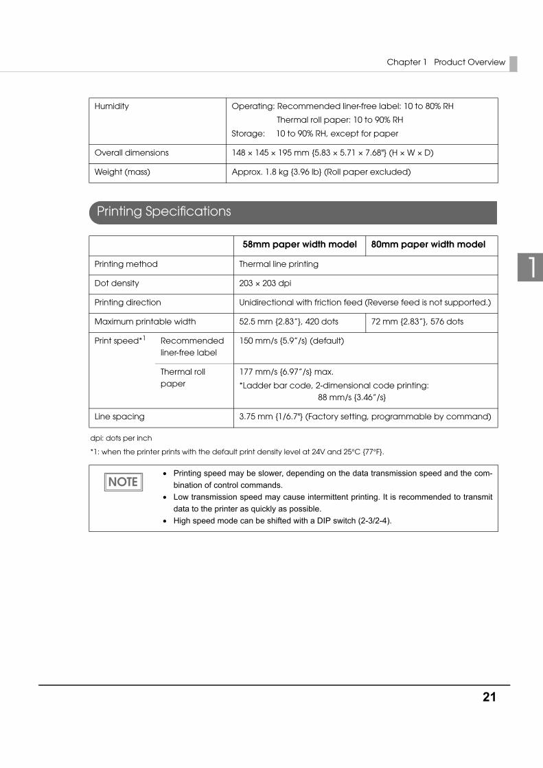
Printing Specifications
dpi: dots per inch
*1: when the printer prints with the default print density level at 24V and 25°C {77°F}.
Humidity Operating: Recommended liner-free label: 10 to 80% RH
Thermal roll paper: 10 to 90% RH
Storage: 10 to 90% RH, except for paper
Overall dimensions 148 × 145 × 195 mm {5.83 × 5.71 × 7.68"} (H × W × D)
Weight (mass) Approx. 1.8 kg {3.96 lb} (Roll paper excluded)
58mm paper width model 80mm paper width model
Printing method Thermal line printing
Dot density 203 × 203 dpi
Printing direction Unidirectional with friction feed (Reverse feed is not supported.)
Maximum printable width 52.5 mm {2.83”}, 420 dots 72 mm {2.83”}, 576 dots
Print speed*1 Recommended liner-free label
150 mm/s {5.9”/s] (default)
Thermal roll paper
177 mm/s {6.97”/s} max.
*Ladder bar code, 2-dimensional code printing: 88 mm/s {3.46”/s}
Line spacing 3.75 mm {1/6.7"} (Factory setting, programmable by command)
• Printing speed may be slower, depending on the data transmission speed and the com-bination of control commands.
• Low transmission speed may cause intermittent printing. It is recommended to transmit data to the printer as quickly as possible.
• High speed mode can be shifted with a DIP switch (2-3/2-4).
22
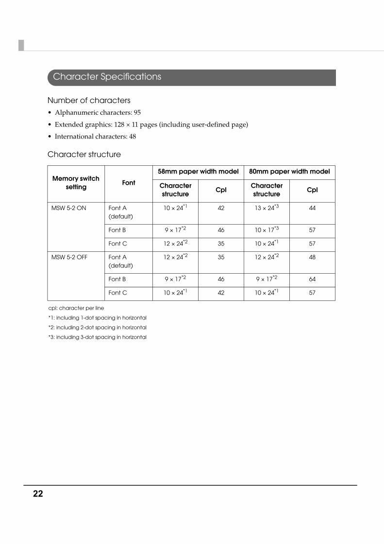
Character Specifications
Number of characters
• Alphanumeric characters: 95
• Extended graphics: 128 × 11 pages (including user-defined page)
• International characters: 48
Character structure
cpl: character per line
*1: including 1-dot spacing in horizontal
*2: including 2-dot spacing in horizontal
*3: including 3-dot spacing in horizontal
Memory switch setting
Font
58mm paper width model 80mm paper width model
Character structure
CplCharacter structure
Cpl
MSW 5-2 ON Font A (default)
10 × 24*1 42 13 × 24*3 44
Font B 9 × 17*2 46 10 × 17*3 57
Font C 12 × 24*2 35 10 × 24*1 57
MSW 5-2 OFF Font A (default)
12 × 24*2 35 12 × 24*2 48
Font B 9 × 17*2 46 9 × 17*2 64
Font C 10 × 24*1 42 10 × 24*1 57
Chapter 1 Product Overview
23
1
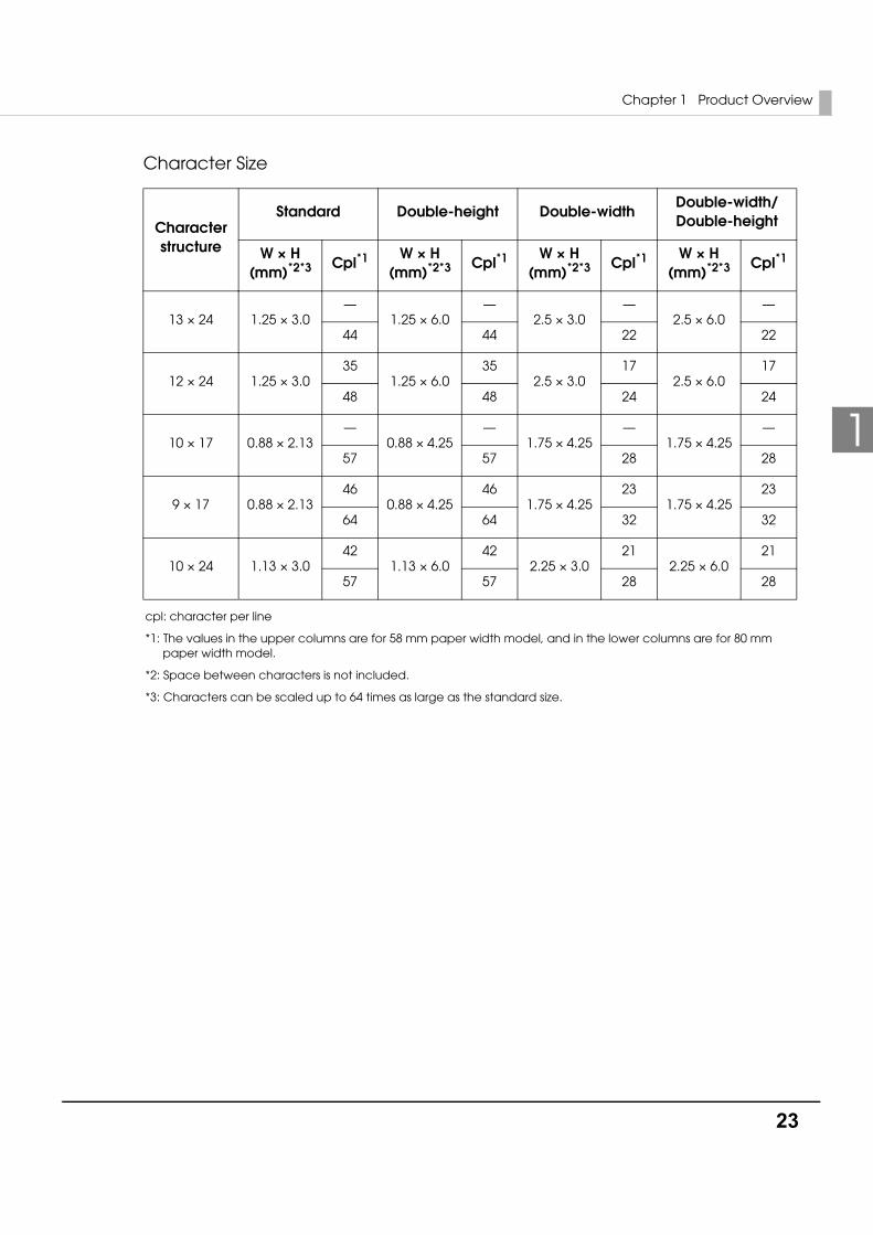
Character Size
cpl: character per line
*1: The values in the upper columns are for 58 mm paper width model, and in the lower columns are for 80 mm paper width model.
*2: Space between characters is not included.
*3: Characters can be scaled up to 64 times as large as the standard size.
Character structure
Standard Double-height Double-widthDouble-width/Double-height
W × H (mm)*2*3 Cpl*1 W × H
(mm)*2*3 Cpl*1 W × H (mm)*2*3 Cpl*1 W × H
(mm)*2*3 Cpl*1
13 × 24 1.25 × 3.0—
1.25 × 6.0—
2.5 × 3.0—
2.5 × 6.0—
44 44 22 22
12 × 24 1.25 × 3.035
1.25 × 6.035
2.5 × 3.017
2.5 × 6.017
48 48 24 24
10 × 17 0.88 × 2.13—
0.88 × 4.25—
1.75 × 4.25—
1.75 × 4.25—
57 57 28 28
9 × 17 0.88 × 2.1346
0.88 × 4.2546
1.75 × 4.2523
1.75 × 4.2523
64 64 32 32
10 × 24 1.13 × 3.042
1.13 × 6.042
2.25 × 3.021
2.25 × 6.021
57 57 28 28
24
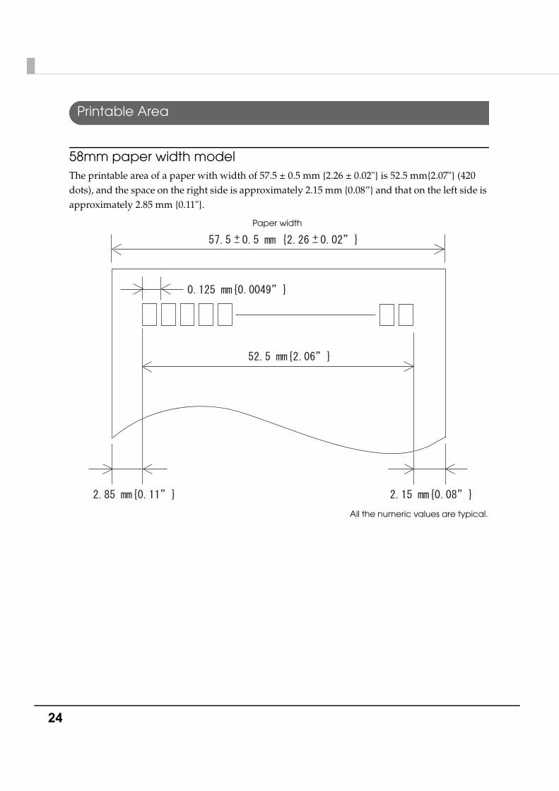
Printable Area
58mm paper width modelThe printable area of a paper with width of 57.5 ± 0.5 mm {2.26 ± 0.02"} is 52.5 mm{2.07"} (420 dots), and the space on the right side is approximately 2.15 mm {0.08”} and that on the left side is approximately 2.85 mm {0.11"}.
All the numeric values are typical.
Paper width
Chapter 1 Product Overview
25
1
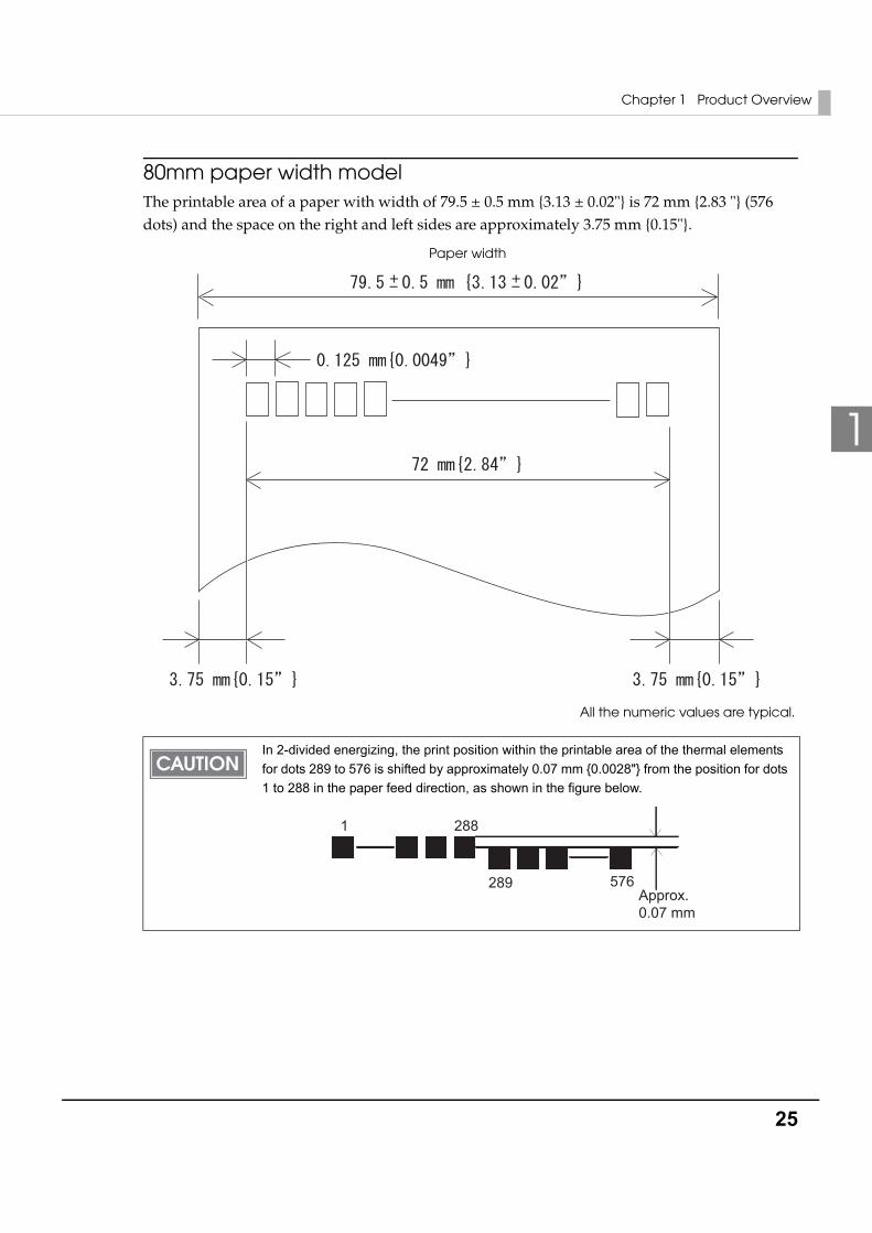
80mm paper width modelThe printable area of a paper with width of 79.5 ± 0.5 mm {3.13 ± 0.02"} is 72 mm {2.83 "} (576 dots) and the space on the right and left sides are approximately 3.75 mm {0.15"}.
In 2-divided energizing, the print position within the printable area of the thermal elements for dots 289 to 576 is shifted by approximately 0.07 mm {0.0028"} from the position for dots 1 to 288 in the paper feed direction, as shown in the figure below.
All the numeric values are typical.
Paper width
2881
289 576Approx.�0.07 mm
26
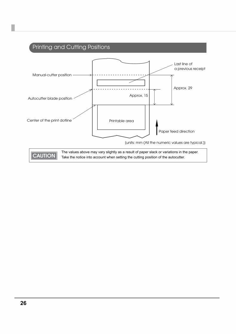
Printing and Cutting Positions
The values above may vary slightly as a result of paper slack or variations in the paper. Take the notice into account when setting the cutting position of the autocutter.
Autocutter blade position
Approx. 29
Approx. 15
Manual-cutter position
Center of the print dotline
[units: mm (All the numeric values are typical.)]
Paper feed direction
Printable area
Last line of a previous receipt
Chapter 1 Product Overview
27
1
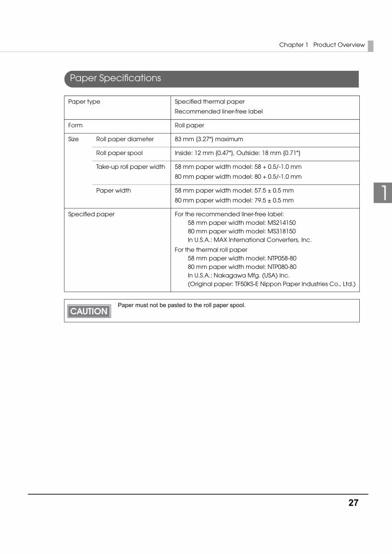
Paper Specifications
Paper type Specified thermal paper
Recommended liner-free label
Form Roll paper
Size Roll paper diameter 83 mm {3.27"} maximum
Roll paper spool Inside: 12 mm {0.47"}, Outside: 18 mm {0.71"}
Take-up roll paper width 58 mm paper width model: 58 + 0.5/-1.0 mm
80 mm paper width model: 80 + 0.5/-1.0 mm
Paper width 58 mm paper width model: 57.5 ± 0.5 mm
80 mm paper width model: 79.5 ± 0.5 mm
Specified paper For the recommended liner-free label: 58 mm paper width model: MS214150 80 mm paper width model: MS318150 In U.S.A.: MAX International Converters, Inc.
For the thermal roll paper 58 mm paper width model: NTP058-80 80 mm paper width model: NTP080-80 In U.S.A.: Nakagawa Mfg. (USA) Inc. (Original paper: TF50KS-E Nippon Paper Industries Co., Ltd.)
Paper must not be pasted to the roll paper spool.
28
Electrical Characteristics
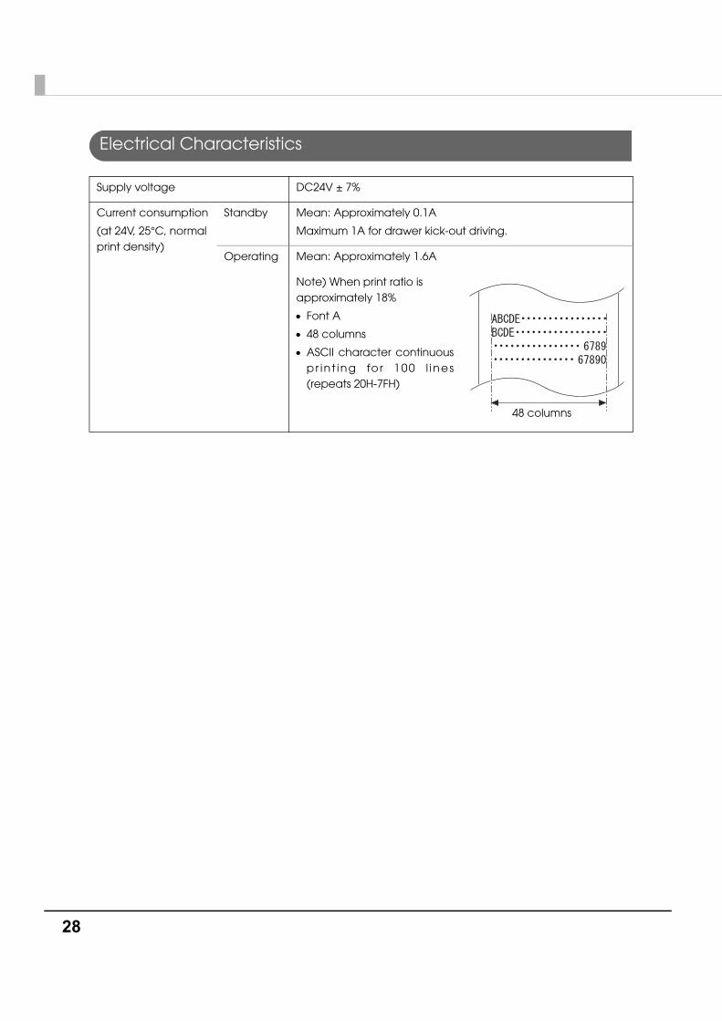
Supply voltage DC24V ± 7%
Current consumption
(at 24V, 25°C, normal print density)
Standby Mean: Approximately 0.1A
Maximum 1A for drawer kick-out driving.
Operating Mean: Approximately 1.6A
Note) When print ratio is approximately 18%
• Font A
• 48 columns
• ASCII character continuous pr in t ing fo r 100 l ines (repeats 20H-7FH)
48 columns
Chapter 1 Product Overview
29
1
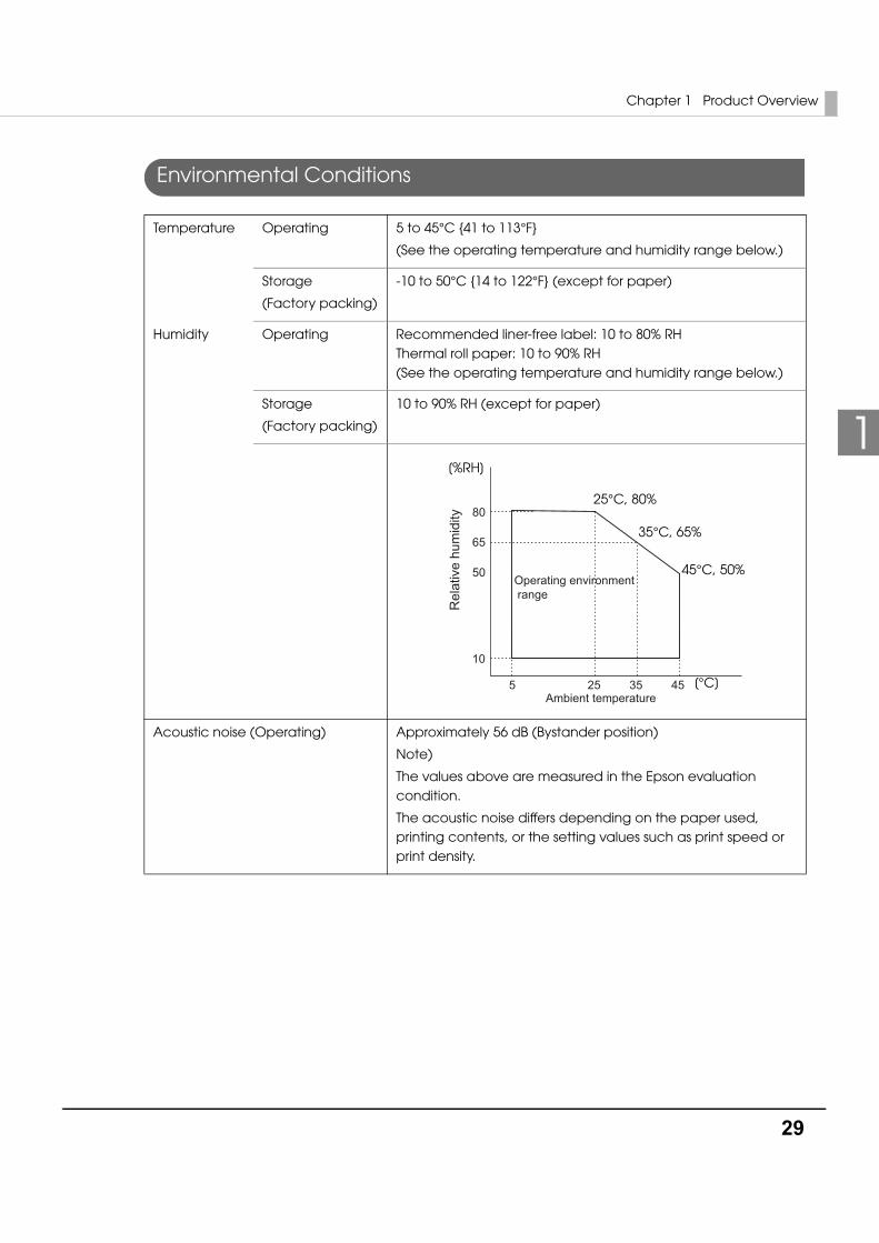
Environmental Conditions
Temperature Operating 5 to 45°C {41 to 113°F}
(See the operating temperature and humidity range below.)
Storage
(Factory packing)
-10 to 50°C {14 to 122°F} (except for paper)
Humidity Operating Recommended liner-free label: 10 to 80% RH Thermal roll paper: 10 to 90% RH (See the operating temperature and humidity range below.)
Storage
(Factory packing)
10 to 90% RH (except for paper)
Acoustic noise (Operating) Approximately 56 dB (Bystander position)
Note)
The values above are measured in the Epson evaluation condition.
The acoustic noise differs depending on the paper used, printing contents, or the setting values such as print speed or print density.
Rel
ativ
e hu
mid
ity
Operating environment range
80
65
50
10
5 3525 45Ambient temperature
[%RH]
25°C, 80%
35°C, 65%
45°C, 50%
[°C]
30
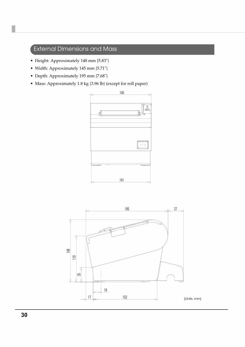
External Dimensions and Mass
• Height: Approximately 148 mm {5.83"}
• Width: Approximately 145 mm {5.71"}
• Depth: Approximately 195 mm {7.68"}
• Mass: Approximately 1.8 kg {3.96 lb} (except for roll paper)
[Units: mm]
Chapter 1 Product Overview
31
1
Power Supply Unit Specifications
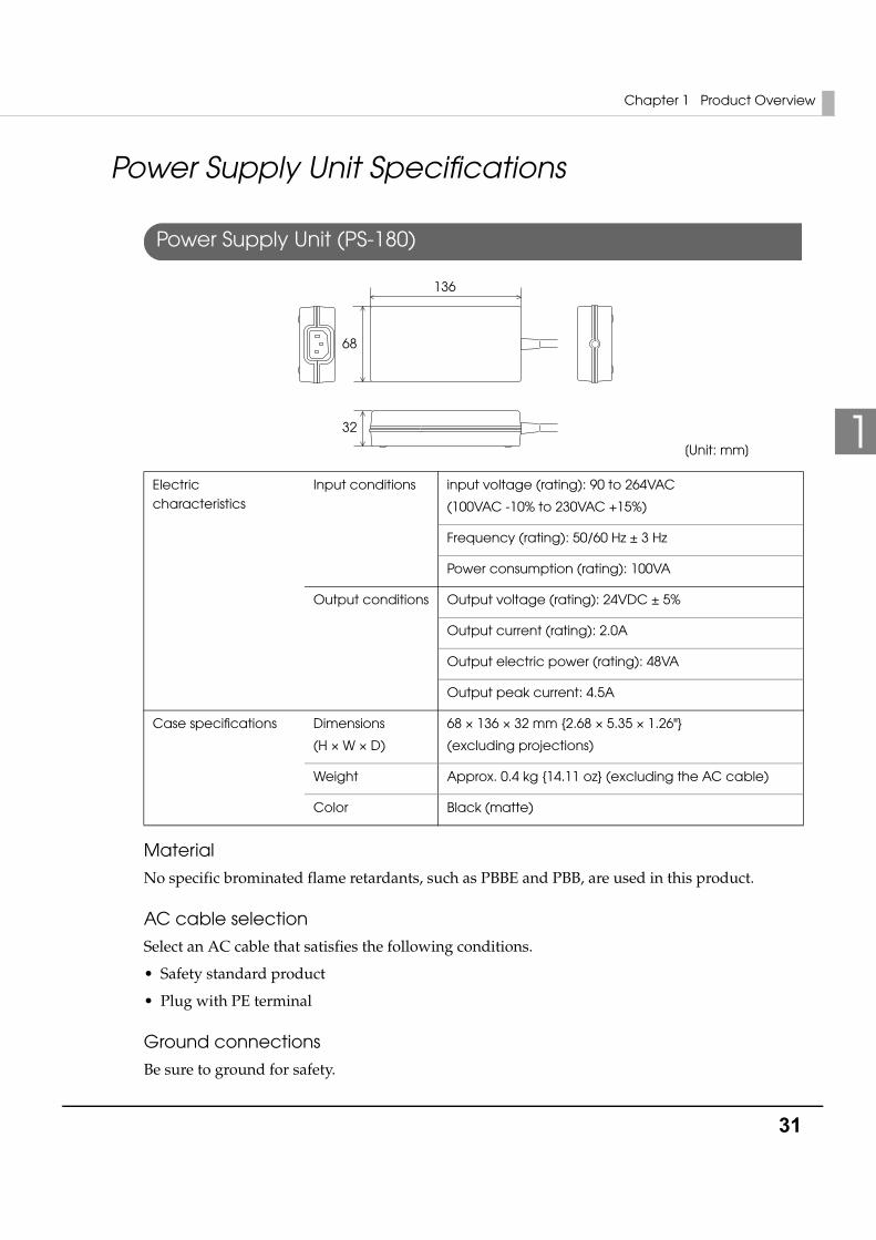
Power Supply Unit (PS-180)
Material
No specific brominated flame retardants, such as PBBE and PBB, are used in this product.
AC cable selection
Select an AC cable that satisfies the following conditions.
• Safety standard product
• Plug with PE terminal
Ground connections
Be sure to ground for safety.
Electric characteristics
Input conditions input voltage (rating): 90 to 264VAC
(100VAC -10% to 230VAC +15%)
Frequency (rating): 50/60 Hz ± 3 Hz
Power consumption (rating): 100VA
Output conditions Output voltage (rating): 24VDC ± 5%
Output current (rating): 2.0A
Output electric power (rating): 48VA
Output peak current: 4.5A
Case specifications Dimensions
(H × W × D)
68 × 136 × 32 mm {2.68 × 5.35 × 1.26"}
(excluding projections)
Weight Approx. 0.4 kg {14.11 oz} (excluding the AC cable)
Color Black (matte)
[Unit: mm]
136
68
32

32
Chapter 2 Setup
33
2
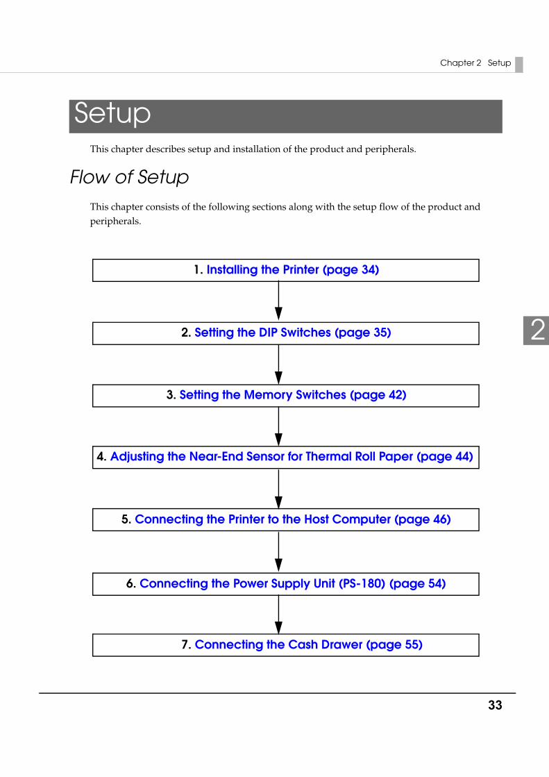
SetupThis chapter describes setup and installation of the product and peripherals.
Flow of SetupThis chapter consists of the following sections along with the setup flow of the product and peripherals.
1. Installing the Printer (page 34)
6. Connecting the Power Supply Unit (PS-180) (page 54)
5. Connecting the Printer to the Host Computer (page 46)
3. Setting the Memory Switches (page 42)
7. Connecting the Cash Drawer (page 55)
2. Setting the DIP Switches (page 35)
4. Adjusting the Near-End Sensor for Thermal Roll Paper (page 44)
34
Installing the PrinterYou can install this printer horizontally. With an optional hanging bracket (WH-10), you can also attach the printer to a wall.
Important Notes on Horizontal Installation
• The printer must be installed horizontally.
• Do not place the printer in dusty locations.
• Do not put heavy impacts on the printer. They may cause defective print.
• Do not catch cables or foreign matter under the printer.
Important Notes on Wall Hanging
You need to perform the following tasks to install the printer on a wall. For more details, see the installation manual for the optional wall hanging bracket (WH-10).
• Installing the roll-paper stoppers
• Changing the location of the roll paper near-end sensor
• Attaching the connector cover
• Attaching the wall hanging bracket (WH-10)
For the other notes, see the installation manual for the optional wall hanging bracket (WH-10).
CAUTION
Be sure to attach the connector cover when you use the printer on a wall using the wall hanging bracket.
Chapter 2 Setup
35
2
Setting the DIP SwitchesOn this printer, you can make various settings with DIP switches.
Functions of the DIP switches differ depending on the interface.
Setting Procedure
Follow the steps below to change the DIP switch settings.
1 Make sure the power supply for the printer is turned off.
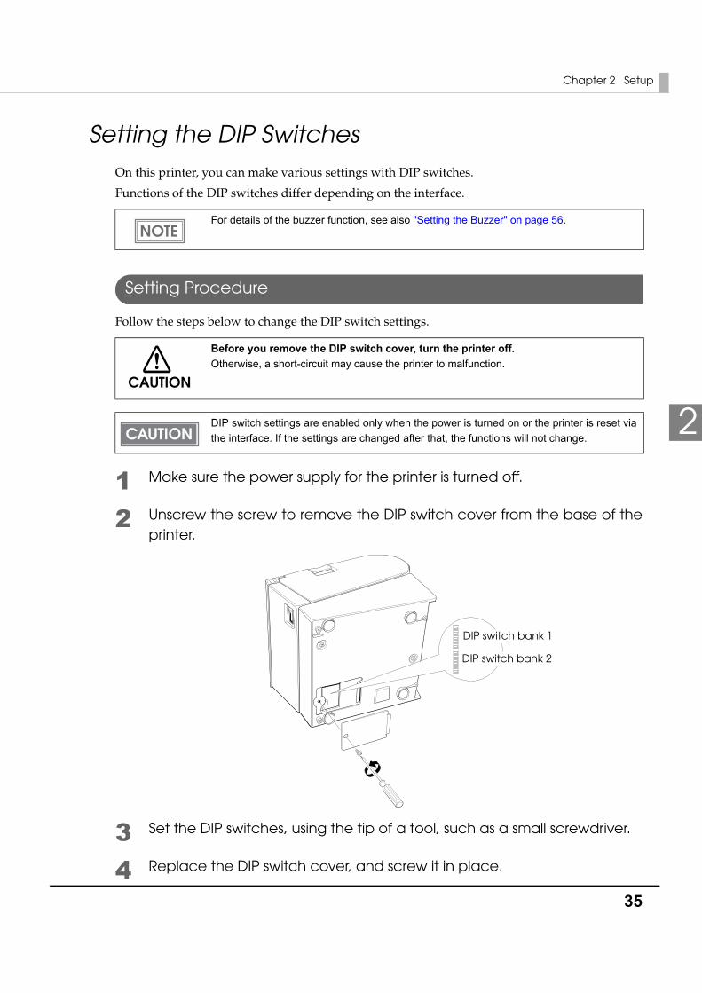
2 Unscrew the screw to remove the DIP switch cover from the base of the printer.
3 Set the DIP switches, using the tip of a tool, such as a small screwdriver.
4 Replace the DIP switch cover, and screw it in place.
For details of the buzzer function, see also "Setting the Buzzer" on page 56.
CAUTION
Before you remove the DIP switch cover, turn the printer off. Otherwise, a short-circuit may cause the printer to malfunction.
DIP switch settings are enabled only when the power is turned on or the printer is reset via the interface. If the settings are changed after that, the functions will not change.
DIP switch bank 1
DIP switch bank 2
36
For Serial Interface
DIP Switch Bank 1
Transmission speed (DIP switch 1-7/1-8)
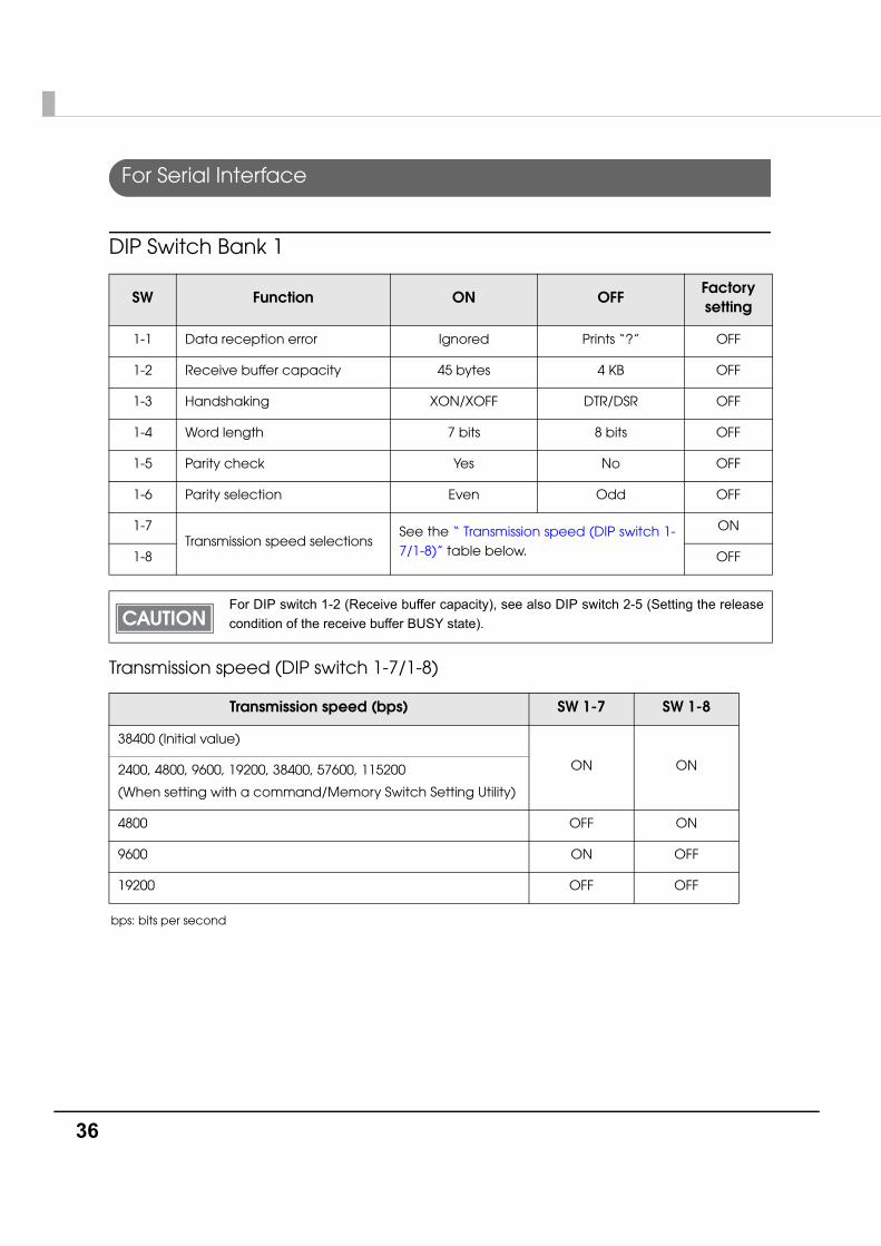
bps: bits per second
SW Function ON OFFFactorysetting
1-1 Data reception error Ignored Prints “?” OFF
1-2 Receive buffer capacity 45 bytes 4 KB OFF
1-3 Handshaking XON/XOFF DTR/DSR OFF
1-4 Word length 7 bits 8 bits OFF
1-5 Parity check Yes No OFF
1-6 Parity selection Even Odd OFF
1-7Transmission speed selections
See the “ Transmission speed (DIP switch 1-7/1-8)” table below.
ON
1-8 OFF
For DIP switch 1-2 (Receive buffer capacity), see also DIP switch 2-5 (Setting the release condition of the receive buffer BUSY state).
Transmission speed (bps) SW 1-7 SW 1-8
38400 (Initial value)
ON ON2400, 4800, 9600, 19200, 38400, 57600, 115200
(When setting with a command/Memory Switch Setting Utility)
4800 OFF ON
9600 ON OFF
19200 OFF OFF
Chapter 2 Setup
37
2
DIP Switch Bank 2
• The transmission speed can be set with a command or the memory switch utility. (Setting values: 2400, 4800, 9600, 19200, 38400, 57600, 115200) The value set with a command or the memory switch utility is enabled only when DIP switches 1-7 and 1-8 are on. For other settings, the value set with the DIP switches is enabled.
• Depending on print conditions such as print duty, print head temperature, and data transmission speed, print speed is automatically adjusted, which can cause white lines due to intermittent print (the motor sometimes stops). To avoid this, set the transmission speed higher or keep the print speed constant by setting it lower. (See "Setting the Memory Switches" on page 42.)
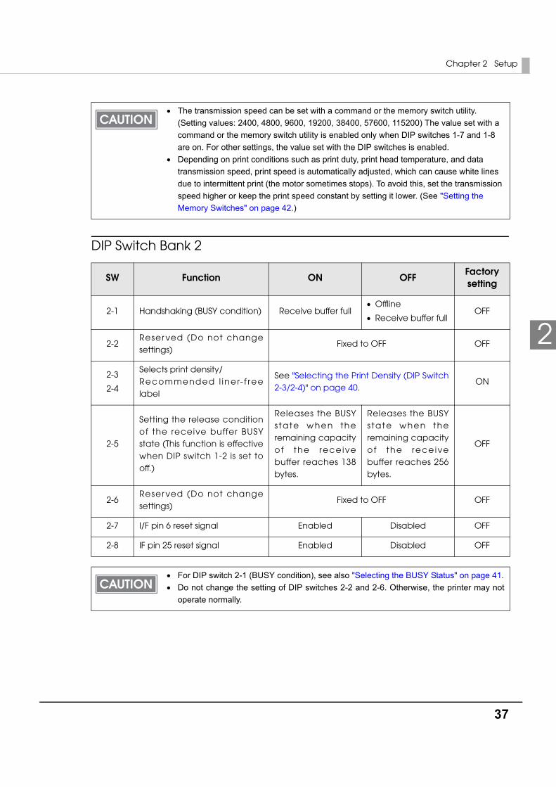
SW Function ON OFFFactorysetting
2-1 Handshaking (BUSY condition) Receive buffer full• Offline
• Receive buffer fullOFF
2-2Reser ved (Do not change settings)
Fixed to OFF OFF
2-3
2-4
Selects print density/ Recommended l iner- f ree label
See "Selecting the Print Density (DIP Switch 2-3/2-4)" on page 40.
ON
2-5
Setting the release condition of the receive buffer BUSY state (This function is effective when DIP switch 1-2 is set to off.)
Releases the BUSY s tate w hen the remaining capacity of the rece ive buffer reaches 138 bytes.
Releases the BUSY s tate when the remaining capacity o f the rece ive buffer reaches 256 bytes.
OFF
2-6Reser ved (Do not change settings)
Fixed to OFF OFF
2-7 I/F pin 6 reset signal Enabled Disabled OFF
2-8 IF pin 25 reset signal Enabled Disabled OFF
• For DIP switch 2-1 (BUSY condition), see also "Selecting the BUSY Status" on page 41.• Do not change the setting of DIP switches 2-2 and 2-6. Otherwise, the printer may not
operate normally.
38
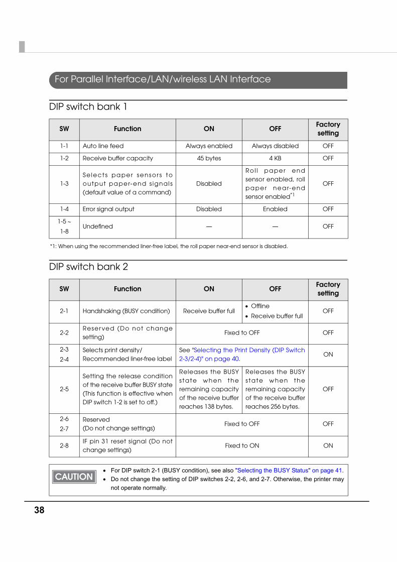
For Parallel Interface/LAN/wireless LAN Interface
DIP switch bank 1
*1: When using the recommended liner-free label, the roll paper near-end sensor is disabled.
DIP switch bank 2
SW Function ON OFFFactorysetting
1-1 Auto line feed Always enabled Always disabled OFF
1-2 Receive buffer capacity 45 bytes 4 KB OFF
1-3Se lect s pa per sensor s to output pa per-end s ignals (default value of a command)
Disabled
Rol l pa per end sensor enabled, roll pa per near-end sensor enabled*1
OFF
1-4 Error signal output Disabled Enabled OFF
1-5 ∼
1-8Undefined — — OFF
SW Function ON OFFFactorysetting
2-1 Handshaking (BUSY condition) Receive buffer full• Offline
• Receive buffer fullOFF
2-2Reser ved (Do not change setting)
Fixed to OFF OFF
2-3
2-4
Selects print density/ Recommended liner-free label
See "Selecting the Print Density (DIP Switch 2-3/2-4)" on page 40.
ON
2-5
Setting the release condition of the receive buffer BUSY state (This function is effective when DIP switch 1-2 is set to off.)
Releases the BUSY s tate w hen the remaining capacity of the receive buffer reaches 138 bytes.
Releases the BUSY s tate when the remaining capacity of the receive buffer reaches 256 bytes.
OFF
2-6
2-7
Reserved (Do not change settings)
Fixed to OFF OFF
2-8IF pin 31 reset signal (Do not change settings)
Fixed to ON ON
• For DIP switch 2-1 (BUSY condition), see also "Selecting the BUSY Status" on page 41.• Do not change the setting of DIP switches 2-2, 2-6, and 2-7. Otherwise, the printer may
not operate normally.
Chapter 2 Setup
39
2
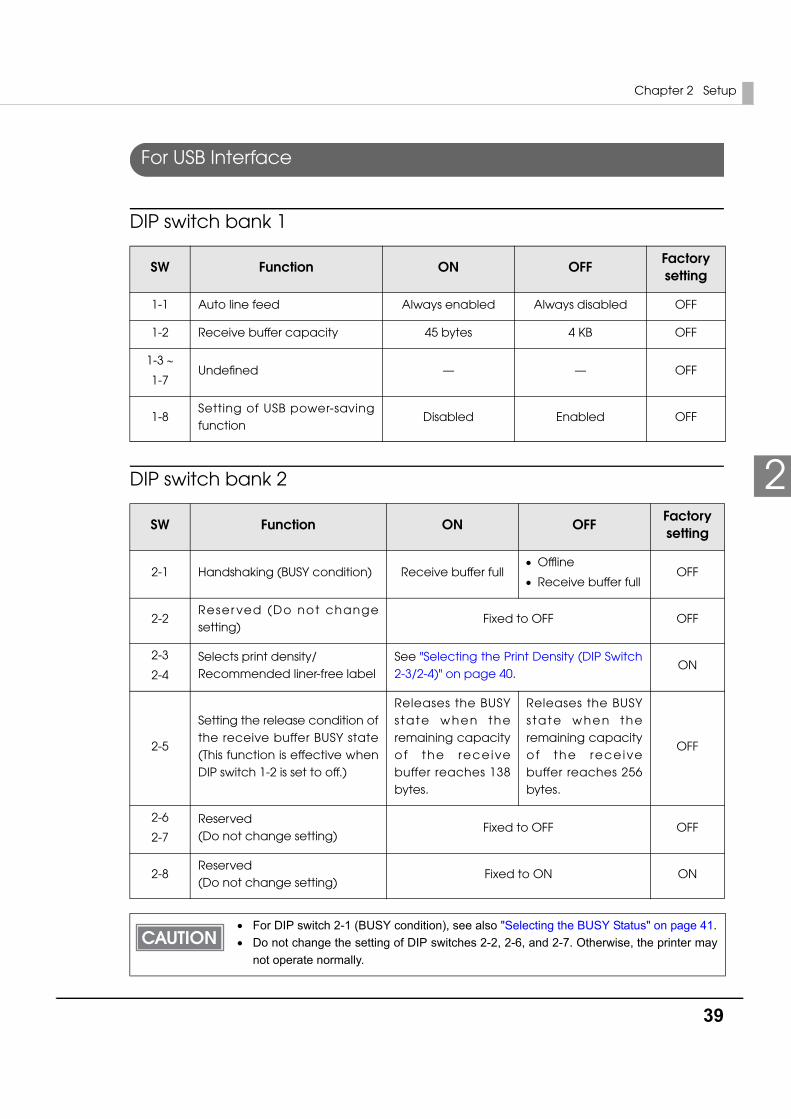
For USB Interface
DIP switch bank 1
DIP switch bank 2
SW Function ON OFFFactorysetting
1-1 Auto line feed Always enabled Always disabled OFF
1-2 Receive buffer capacity 45 bytes 4 KB OFF
1-3 ∼
1-7Undefined — — OFF
1-8Setting of USB power-saving function
Disabled Enabled OFF
SW Function ON OFFFactorysetting
2-1 Handshaking (BUSY condition) Receive buffer full• Offline
• Receive buffer fullOFF
2-2Reser ved (Do not change setting)
Fixed to OFF OFF
2-3
2-4
Selects print density/ Recommended liner-free label
See "Selecting the Print Density (DIP Switch 2-3/2-4)" on page 40.
ON
2-5
Setting the release condition of the receive buffer BUSY state (This function is effective when DIP switch 1-2 is set to off.)
Releases the BUSY s tate w hen the remaining capacity of the rece ive buffer reaches 138 bytes.
Releases the BUSY s tate when the remaining capacity o f the rece ive buffer reaches 256 bytes.
OFF
2-6
2-7
Reserved (Do not change setting)
Fixed to OFF OFF
2-8Reserved (Do not change setting)
Fixed to ON ON
• For DIP switch 2-1 (BUSY condition), see also "Selecting the BUSY Status" on page 41.• Do not change the setting of DIP switches 2-2, 2-6, and 2-7. Otherwise, the printer may
not operate normally.
40
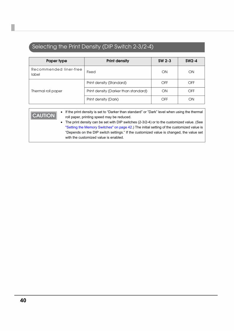
Selecting the Print Density (DIP Switch 2-3/2-4)
Paper type Print density SW 2-3 SW2-4
Recommended l iner-f ree label
Fixed ON ON
Thermal roll paper
Print density (Standard) OFF OFF
Print density (Darker than standard) ON OFF
Print density (Dark) OFF ON
• If the print density is set to “Darker than standard” or ”Dark” level when using the thermal roll paper, printing speed may be reduced.
• The print density can be set with DIP switches (2-3/2-4) or to the customized value. (See "Setting the Memory Switches" on page 42.) The initial setting of the customized value is “Depends on the DIP switch settings.” If the customized value is changed, the value set with the customized value is enabled.
Chapter 2 Setup
41
2
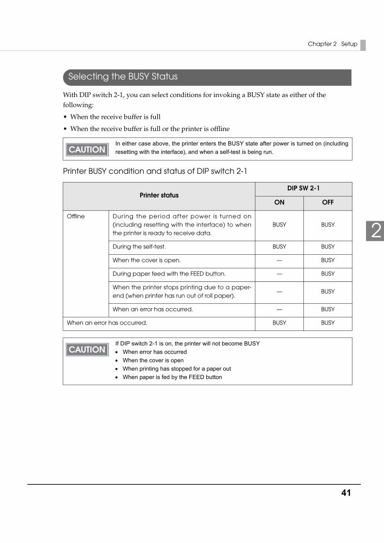
Selecting the BUSY Status
With DIP switch 2-1, you can select conditions for invoking a BUSY state as either of the following:
• When the receive buffer is full
• When the receive buffer is full or the printer is offline
Printer BUSY condition and status of DIP switch 2-1
In either case above, the printer enters the BUSY state after power is turned on (including resetting with the interface), and when a self-test is being run.
Printer statusDIP SW 2-1
ON OFF
Offline Dur ing the per iod after power is turned on (including resetting with the interface) to when the printer is ready to receive data.
BUSY BUSY
During the self-test. BUSY BUSY
When the cover is open. — BUSY
During paper feed with the FEED button. — BUSY
When the printer stops printing due to a paper-end (when printer has run out of roll paper).
— BUSY
When an error has occurred. — BUSY
When an error has occurred. BUSY BUSY
If DIP switch 2-1 is on, the printer will not become BUSY• When error has occurred• When the cover is open• When printing has stopped for a paper out• When paper is fed by the FEED button
42
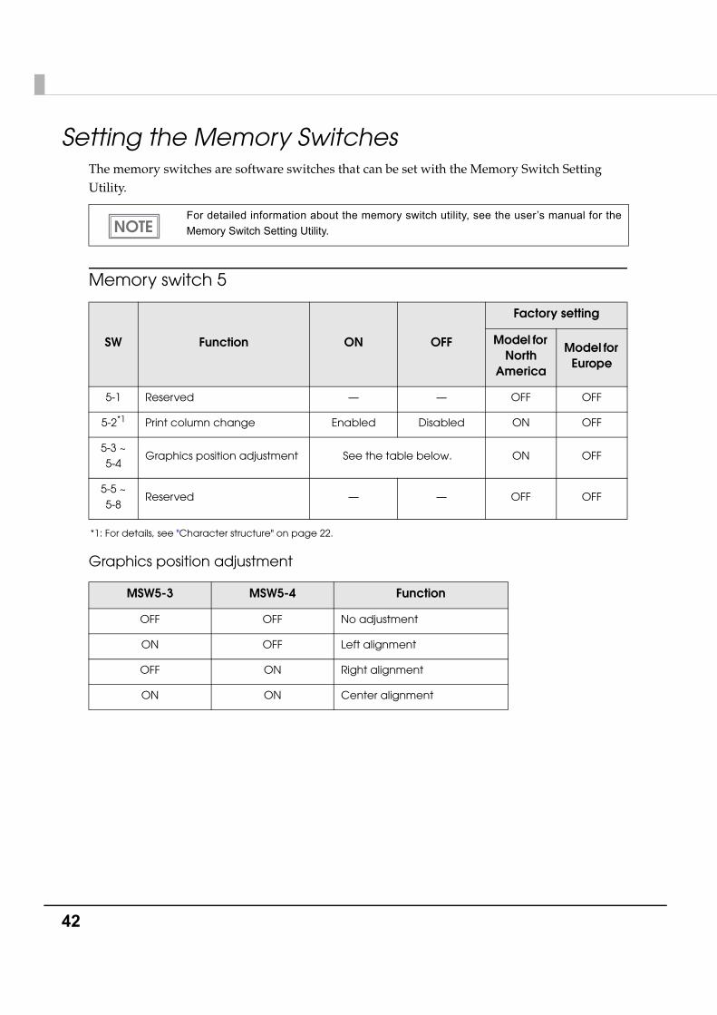
Setting the Memory SwitchesThe memory switches are software switches that can be set with the Memory Switch Setting Utility.
Memory switch 5
*1: For details, see "Character structure" on page 22.
Graphics position adjustment
For detailed information about the memory switch utility, see the user’s manual for the Memory Switch Setting Utility.
SW Function ON OFF
Factory setting
Model for North
America
Model for Europe
5-1 Reserved — — OFF OFF
5-2*1 Print column change Enabled Disabled ON OFF
5-3 ~5-4
Graphics position adjustment See the table below. ON OFF
5-5 ~5-8
Reserved — — OFF OFF
MSW5-3 MSW5-4 Function
OFF OFF No adjustment
ON OFF Left alignment
OFF ON Right alignment
ON ON Center alignment
Chapter 2 Setup
43
2
Customized valueThe following items can be set as the customized value with the Memory Switch Setting Utility or a command.
• Print density
• Print speed
• Number of head energizing parts
Selecting the print density
Selectable from levels 1 to 13 (light ∼ dark).
Selecting the print speed
Selectable from levels 1 to 9 (low ∼ high). (Initial setting: level 9)
Selecting the number of head energizing parts
• One-part energizing
• Two-part energizing
• Auto energizing (Initial setting)
The print density can be set with DIP switches (2-3/2-4) or the customized value. (See "Setting the Memory Switches" on page 42.) The initial setting of the customized value is “Depends on the DIP switch settings.” If the customized value is changed, the value set with the customized value is enabled.
Depending on print conditions such as print duty, print head temperature, or data transmission speed, print speed is automatically adjusted which may cause white lines due to intermittent print (the motor sometimes stops). To avoid this, keep the print speed constant by setting it lower, or set the transmission speed higher in case of the serial interface. (See "Transmission speed (DIP switch 1-7/1-8)" on page 36.)
• Usually, the number of head energizing parts does not need to be changed.• When auto energizing is selected, the printer usually prints in one-part energizing, but it
automatically shifts to two-part energizing if print duty is high.
44
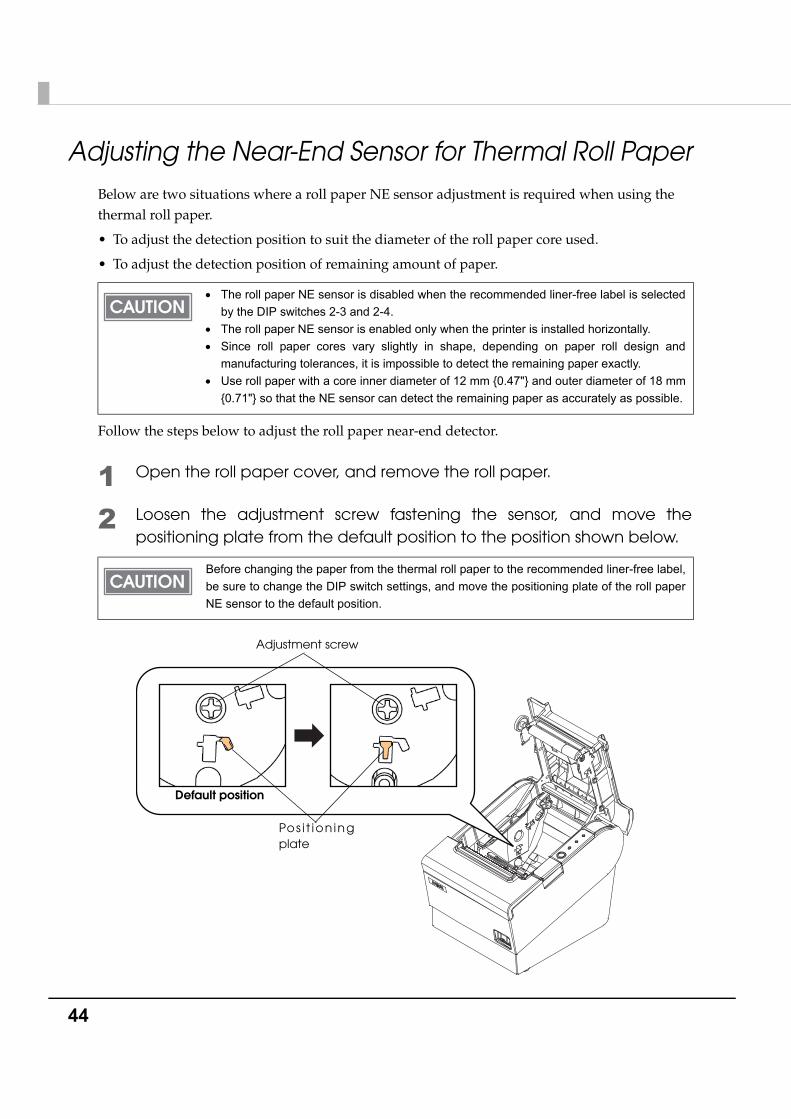
Adjusting the Near-End Sensor for Thermal Roll PaperBelow are two situations where a roll paper NE sensor adjustment is required when using the thermal roll paper.
• To adjust the detection position to suit the diameter of the roll paper core used.
• To adjust the detection position of remaining amount of paper.
Follow the steps below to adjust the roll paper near-end detector.
1 Open the roll paper cover, and remove the roll paper.
2 Loosen the adjustment screw fastening the sensor, and move the positioning plate from the default position to the position shown below.
• The roll paper NE sensor is disabled when the recommended liner-free label is selected by the DIP switches 2-3 and 2-4.
• The roll paper NE sensor is enabled only when the printer is installed horizontally.• Since roll paper cores vary slightly in shape, depending on paper roll design and
manufacturing tolerances, it is impossible to detect the remaining paper exactly.• Use roll paper with a core inner diameter of 12 mm {0.47"} and outer diameter of 18 mm
{0.71"} so that the NE sensor can detect the remaining paper as accurately as possible.
Before changing the paper from the thermal roll paper to the recommended liner-free label, be sure to change the DIP switch settings, and move the positioning plate of the roll paper NE sensor to the default position.
Adjustment screw
Pos i t ion ing plate
Default position
Chapter 2 Setup
45
2
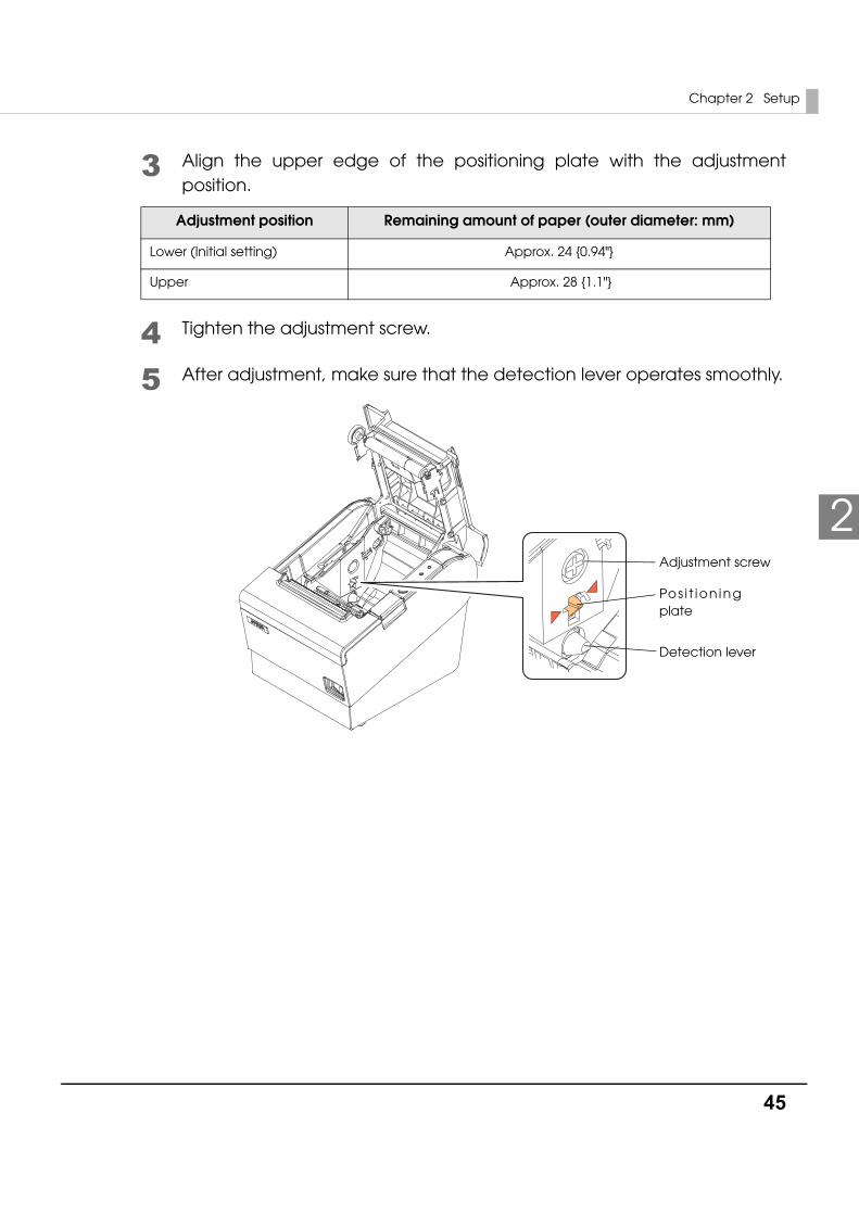
3 Align the upper edge of the positioning plate with the adjustment position.
4 Tighten the adjustment screw.
5 After adjustment, make sure that the detection lever operates smoothly.
Adjustment position Remaining amount of paper (outer diameter: mm)
Lower (Initial setting) Approx. 24 {0.94"}
Upper Approx. 28 {1.1"}
Adjustment screw
Pos i t ion ing plate
Detection lever
46
Connecting the Printer to the Host Computer
For Serial Interface
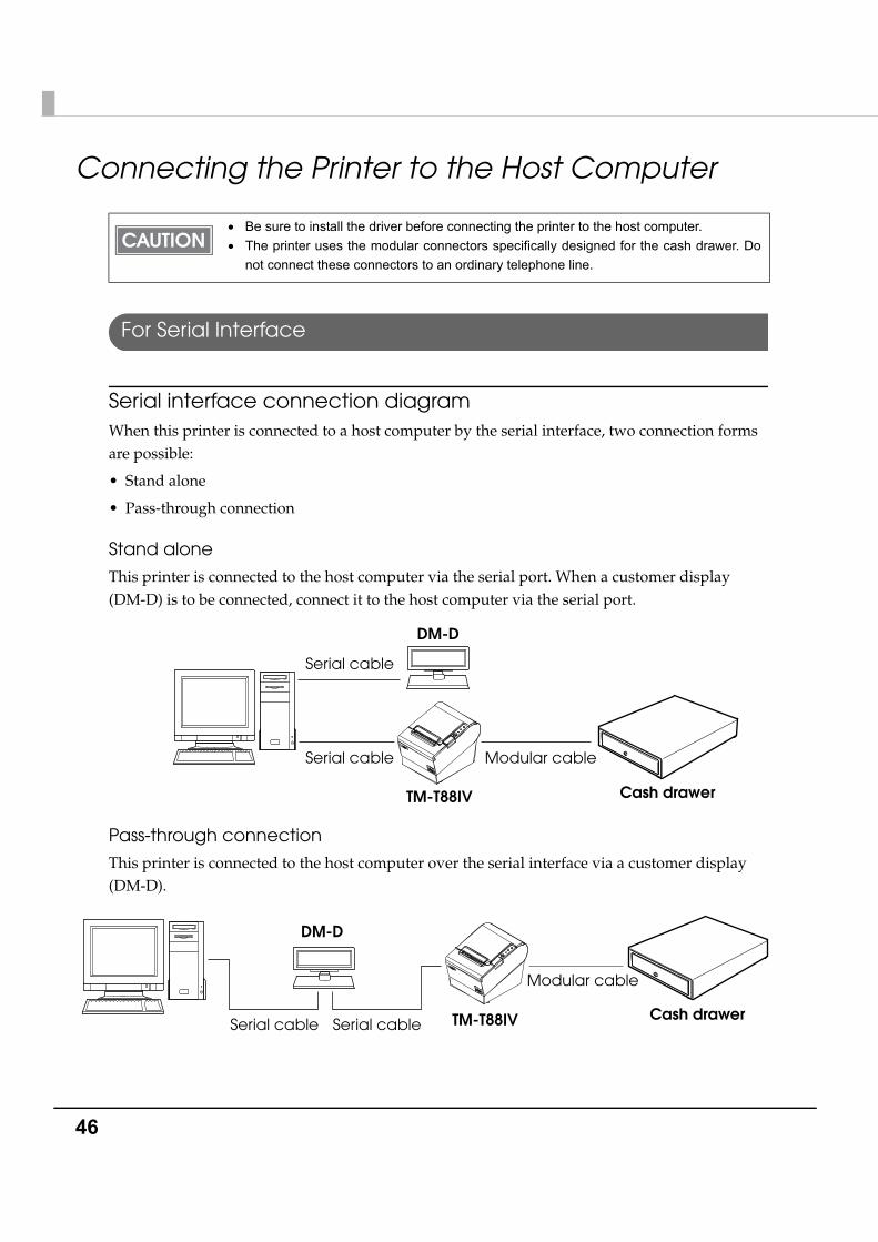
Serial interface connection diagramWhen this printer is connected to a host computer by the serial interface, two connection forms are possible:
• Stand alone
• Pass-through connection
Stand alone
This printer is connected to the host computer via the serial port. When a customer display (DM-D) is to be connected, connect it to the host computer via the serial port.
Pass-through connection
This printer is connected to the host computer over the serial interface via a customer display (DM-D).
• Be sure to install the driver before connecting the printer to the host computer.• The printer uses the modular connectors specifically designed for the cash drawer. Do
not connect these connectors to an ordinary telephone line.
TM-T88IV
DM-D
Serial cable
Cash drawer
Serial cable Modular cable
DM-D
TM-T88IV Cash drawerSerial cable Serial cable
Modular cable
Chapter 2 Setup
47
2
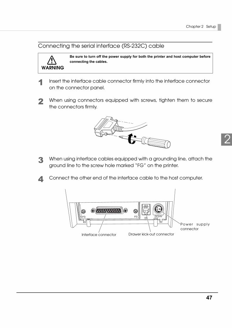
Connecting the serial interface (RS-232C) cable
1 Insert the interface cable connector firmly into the interface connector on the connector panel.
2 When using connectors equipped with screws, tighten them to secure the connectors firmly.
3 When using interface cables equipped with a grounding line, attach the ground line to the screw hole marked “FG” on the printer.
4 Connect the other end of the interface cable to the host computer.
WARNING
Be sure to turn off the power supply for both the printer and host computer before connecting the cables.
DKDC24VFGFG
Drawer kick-out connector
Power supply connector
Interface connector
48
For Parallel Interface
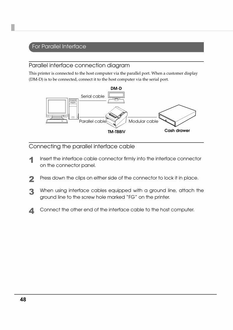
Parallel interface connection diagramThis printer is connected to the host computer via the parallel port. When a customer display (DM-D) is to be connected, connect it to the host computer via the serial port.
Connecting the parallel interface cable
1 Insert the interface cable connector firmly into the interface connector on the connector panel.
2 Press down the clips on either side of the connector to lock it in place.
3 When using interface cables equipped with a ground line, attach the ground line to the screw hole marked “FG” on the printer.
4 Connect the other end of the interface cable to the host computer.
TM-T88IV
DM-D
Serial cable
Cash drawer
Parallel cable Modular cable
Chapter 2 Setup
49
2
For USB Interface
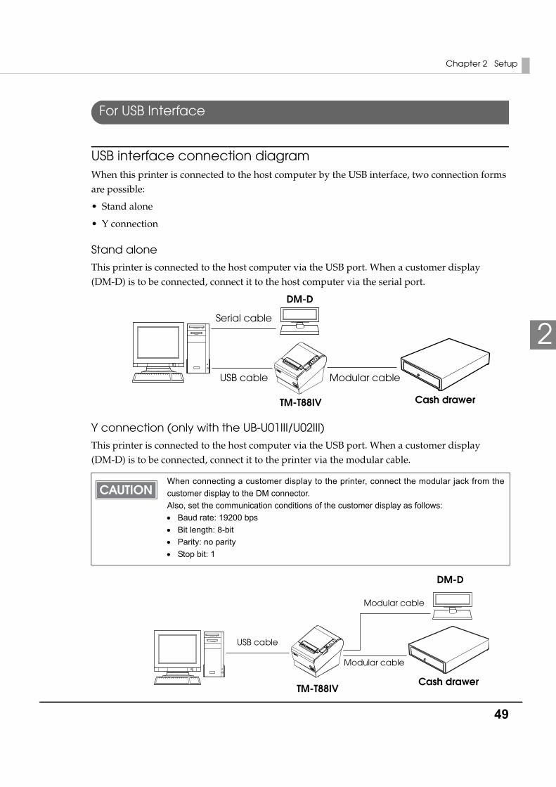
USB interface connection diagramWhen this printer is connected to the host computer by the USB interface, two connection forms are possible:
• Stand alone
• Y connection
Stand alone
This printer is connected to the host computer via the USB port. When a customer display (DM-D) is to be connected, connect it to the host computer via the serial port.
Y connection (only with the UB-U01III/U02III)
This printer is connected to the host computer via the USB port. When a customer display (DM-D) is to be connected, connect it to the printer via the modular cable.
When connecting a customer display to the printer, connect the modular jack from the customer display to the DM connector.Also, set the communication conditions of the customer display as follows:• Baud rate: 19200 bps• Bit length: 8-bit• Parity: no parity• Stop bit: 1
TM-T88IV
DM-D
Serial cable
Cash drawer
USB cable Modular cable
TM-T88IV
DM-D
USB cable
Modular cable
Modular cable
Cash drawer
50
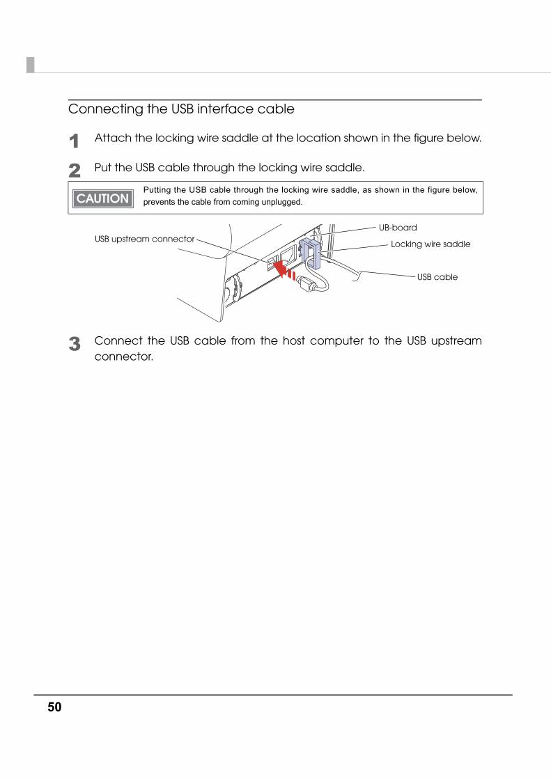
Connecting the USB interface cable
1 Attach the locking wire saddle at the location shown in the figure below.
2 Put the USB cable through the locking wire saddle.
3 Connect the USB cable from the host computer to the USB upstream connector.
Putting the USB cable through the locking wire saddle, as shown in the figure below, prevents the cable from coming unplugged.
UB-board
Locking wire saddle
USB cable
USB upstream connector
Chapter 2 Setup
51
2
For LAN Interface
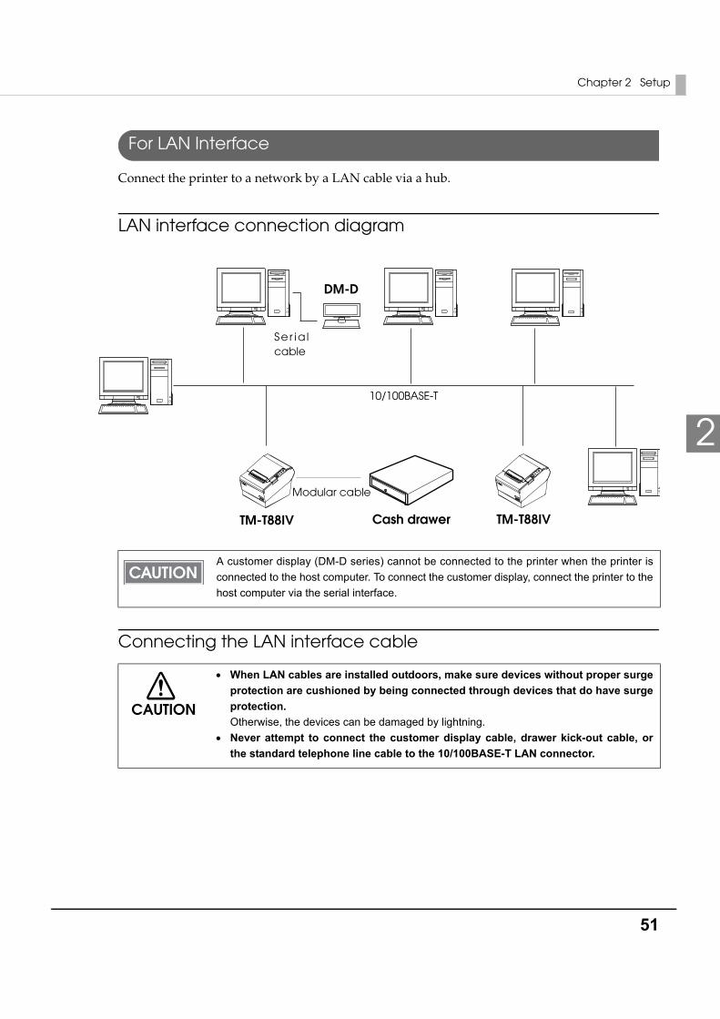
Connect the printer to a network by a LAN cable via a hub.
LAN interface connection diagram
Connecting the LAN interface cable
A customer display (DM-D series) cannot be connected to the printer when the printer is connected to the host computer. To connect the customer display, connect the printer to the host computer via the serial interface.
CAUTION
• When LAN cables are installed outdoors, make sure devices without proper surge protection are cushioned by being connected through devices that do have surge protection. Otherwise, the devices can be damaged by lightning.
• Never attempt to connect the customer display cable, drawer kick-out cable, or the standard telephone line cable to the 10/100BASE-T LAN connector.
TM-T88IV TM-T88IV
Ser ia l cable
Modular cable
Cash drawer
10/100BASE-T
DM-D
52
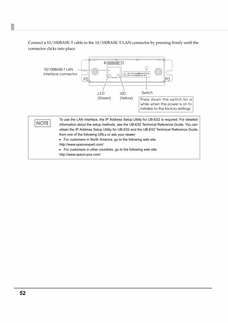
Connect a 10/100BASE-T cable to the 10/100BASE-T LAN connector by pressing firmly until the connector clicks into place.
To use the LAN interface, the IP Address Setup Utility for UB-E02 is required. For detailed information about the setup methods, see the UB-E02 Technical Reference Guide. You can obtain the IP Address Setup Utility for UB-E02 and the UB-E02 Technical Reference Guide from one of the following URLs or ask your dealer:• For customers in North America, go to the following web site:http://www.epsonexpert.com/• For customers in other countries, go to the following web site: http://www.epson-pos.com/
10/100BASE-T LAN interface connector
LED (Green)
LED(Yellow)
Switch
Press down the switch for a while when the power is on to initialize to the factory settings.
Chapter 2 Setup
53
2
For Wireless LAN Interface
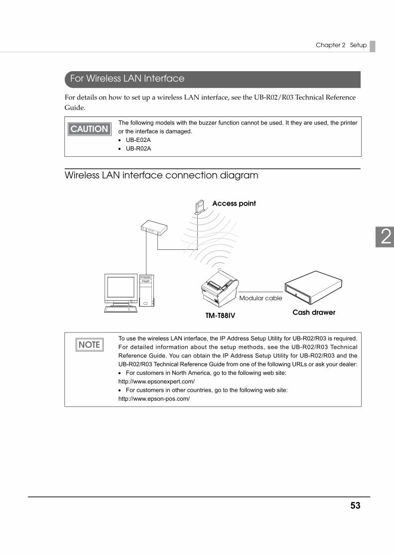
For details on how to set up a wireless LAN interface, see the UB-R02/R03 Technical Reference Guide.
Wireless LAN interface connection diagram
The following models with the buzzer function cannot be used. It they are used, the printer or the interface is damaged.• UB-E02A• UB-R02A
To use the wireless LAN interface, the IP Address Setup Utility for UB-R02/R03 is required. For detailed information about the setup methods, see the UB-R02/R03 Technical Reference Guide. You can obtain the IP Address Setup Utility for UB-R02/R03 and the UB-R02/R03 Technical Reference Guide from one of the following URLs or ask your dealer:• For customers in North America, go to the following web site:http://www.epsonexpert.com/• For customers in other countries, go to the following web site: http://www.epson-pos.com/
TM-T88IV
Modular cable
Cash drawer
Access point
54
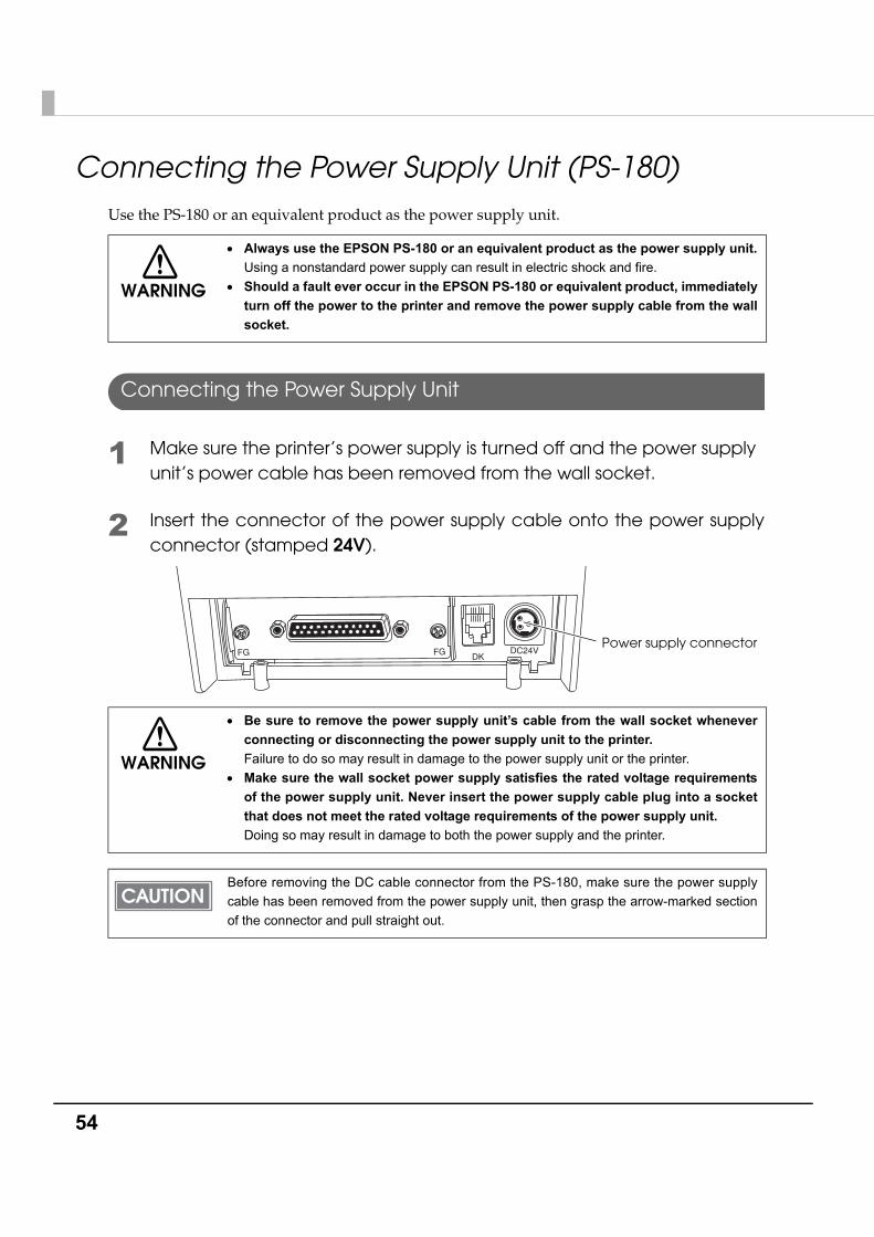
Connecting the Power Supply Unit (PS-180)Use the PS-180 or an equivalent product as the power supply unit.
Connecting the Power Supply Unit
1 Make sure the printer’s power supply is turned off and the power supply unit’s power cable has been removed from the wall socket.
2 Insert the connector of the power supply cable onto the power supply connector (stamped 24V).
WARNING
• Always use the EPSON PS-180 or an equivalent product as the power supply unit. Using a nonstandard power supply can result in electric shock and fire.
• Should a fault ever occur in the EPSON PS-180 or equivalent product, immediately turn off the power to the printer and remove the power supply cable from the wall socket.
WARNING
• Be sure to remove the power supply unit’s cable from the wall socket whenever connecting or disconnecting the power supply unit to the printer. Failure to do so may result in damage to the power supply unit or the printer.
• Make sure the wall socket power supply satisfies the rated voltage requirements of the power supply unit. Never insert the power supply cable plug into a socket that does not meet the rated voltage requirements of the power supply unit. Doing so may result in damage to both the power supply and the printer.
Before removing the DC cable connector from the PS-180, make sure the power supply cable has been removed from the power supply unit, then grasp the arrow-marked section of the connector and pull straight out.
DKDC24VFGFG
Power supply connector
Chapter 2 Setup
55
2
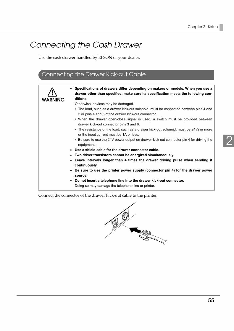
Connecting the Cash DrawerUse the cash drawer handled by EPSON or your dealer.
Connecting the Drawer Kick-out Cable
Connect the connector of the drawer kick-out cable to the printer.
WARNING
• Specifications of drawers differ depending on makers or models. When you use a drawer other than specified, make sure its specification meets the following con-ditions. Otherwise, devices may be damaged.∗ The load, such as a drawer kick-out solenoid, must be connected between pins 4 and
2 or pins 4 and 5 of the drawer kick-out connector.∗ When the drawer open/close signal is used, a switch must be provided between
drawer kick-out connector pins 3 and 6.∗ The resistance of the load, such as a drawer kick-out solenoid, must be 24 Ω or more
or the input current must be 1A or less.∗ Be sure to use the 24V power output on drawer-kick out connector pin 4 for driving the
equipment.• Use a shield cable for the drawer connector cable.• Two driver transistors cannot be energized simultaneously.• Leave intervals longer than 4 times the drawer driving pulse when sending it
continuously.• Be sure to use the printer power supply (connector pin 4) for the drawer power
source.• Do not insert a telephone line into the drawer kick-out connector.
Doing so may damage the telephone line or printer.
56
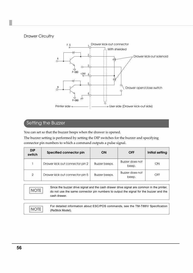
Drawer Circuitry
Setting the Buzzer
You can set so that the buzzer beeps when the drawer is opened.
The buzzer setting is performed by setting the DIP switches for the buzzer and specifying connector pin numbers to which a command outputs a pulse signal.
DIP switch
Specified connector pin ON OFF Initial setting
1 Drawer kick out connector pin 2 Buzzer beeps.Buzzer does not
beep.ON
2 Drawer kick out connector pin 5 Buzzer beeps.Buzzer does not
beep.OFF
Since the buzzer drive signal and the cash drawer drive signal are common in the printer, do not use the same connector pin numbers to output the signal for the buzzer and the cash drawer.
For detailed information about ESC/POS commands, see the TM-T88IV Specification (ReStick Model).
With shielded
Drawer kick-out connector
Printer side User side [Drawer kick-out side]
Drawer open/close switch
Drawer kick-out solenoid
Chapter 3 Application Development Information
57
3
Application Development InformationThis chapter describes how to control the printer and gives information useful for printer application development.
How to Control the PrinterUse a driver or ESC/POS commands to control the printer.
Selecting a Driver
Choose one of the drivers, Advanced Printer Driver (APD) or OPOS ADK, depending on the application operating environment. You cannot control the same printer with both of the drivers.
For information about the driver operating environment, see the installation manual for each driver.
When you newly develop an application• Use APD if you want to print True Type fonts or print much graphics.
• OPOS ADK is recommended for system extensibility. An OPOS driver is provided for various peripherals and it is a POS industry standard now. It enables efficient POS system establishment, reduction of development cost, and effective use of application asset.
When APD is used for your existing applicationUse APD.
When OPOS ADK is used for your existing applicationUse OPOS ADK.
You can use all functions including ones not supported by OPOS ADK or APD by using a driver with ESC/POS command. Use the DIRECT I/O function of OPOS ADK, the control A command of APD, or Status API to send ESC/POS command from each driver. (See "ESC/POS command functions" on page 61.)

58
Precautions on Using a Driver
When using a driver (APD or OPOS ADK) for the ReStick model, it is recommended to set Memory switches 5-2 to 5-4 to OFF.
If you use an APD/OPOS driver for the standard/ReStick model while Memory switch 5-2 is set to ON, there are the following limitations on printing. (Check the operation of the driver before using it, since unexpected problems other than those described below may occur.)
Using the APD when Memory switch 5-2 is ON
APD for the standard model
If more than 45 digits (including spaces) of the device font are printed per line, a line feed is inserted.
APD for the ReStick model
• Character and graphic size and paper feeding amount are smaller than when printing with the standard model TM-T88IV.
• Depending on the application, characters may be printed in unexpected positions.
Chapter 3 Application Development Information
59
3
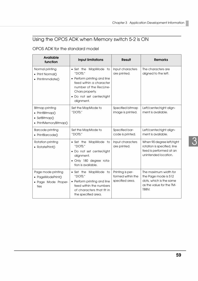
Using the OPOS ADK when Memory switch 5-2 is ON
OPOS ADK for the standard model
Availablefunction
Input limitations Result Remarks
Normal printing
• Print Normal()
• PrintImmdiate()
• Set the MapMode to “DOTS.”
• Perform printing and line feed within a character number of the RecLine-Chars property.
• Do not set center/right alignment.
Input characters are printed.
The characters are aligned to the left.
Bitmap printing
• PrintBitmap()
• SetBitmap()
• PrintMemoryBitmap()
Set the MapMode to “DOTS.”
Specified bitmap image is printed.
Left/center/right align-ment is available.
Barcode printing
• PrintBarcode()
Set the MapMode to “DOTS.”
Specified bar-code is printed.
Left/center/right align-ment is available.
Rotation printing
• RotatePrint()
• Set the MapMode to “DOTS.”
• Do not set center/right alignment.
• Only 180 degree rota-tion is available.
Input characters are printed.
When 90 degree left/right rotation is specified, line feed is performed at an unintended location.
Page mode printing
• PageModePrint()
• Page Mode Proper-ties
• Set the MapMode to “DOTS.”
• Perform printing and line feed within the numbers of characters that fit in the specified area.
Printing is per-formed within the specified area.
The maximum width for the Page mode is 512 dots, which is the same as the value for the TM-T88IV.
60
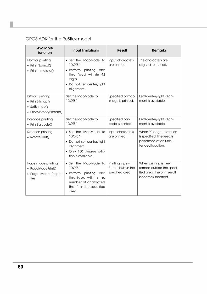
OPOS ADK for the ReStick model
Availablefunction
Input limitations Result Remarks
Normal printing
• Print Normal()
• PrintImmdiate()
• Set the MapMode to “DOTS.”
• Perform printing and l ine feed wi th in 42 digits.
• Do not set center/right alignment.
Input characters are printed.
The characters are aligned to the left.
Bitmap printing
• PrintBitmap()
• SetBitmap()
• PrintMemoryBitmap()
Set the MapMode to “DOTS.”
Specified bitmap image is printed.
Left/center/right align-ment is available.
Barcode printing
• PrintBarcode()
Set the MapMode to “DOTS.”
Specified bar-code is printed.
Left/center/right align-ment is available.
Rotation printing
• RotatePrint()
• Set the MapMode to “DOTS.”
• Do not set center/right alignment.
• Only 180 degree rota-tion is available.
Input characters are printed.
When 90 degree rotation is specified, line feed is performed at an unin-tended location.
Page mode printing
• PageModePrint()
• Page Mode Proper-ties
• Set the MapMode to “DOTS.”
• Perform printing and l ine feed wi th in the number of characters that fit in the specified area.
Printing is per-formed within the specified area.
When printing is per-formed outside the speci-fied area, the print result becomes incorrect.
Chapter 3 Application Development Information
61
3
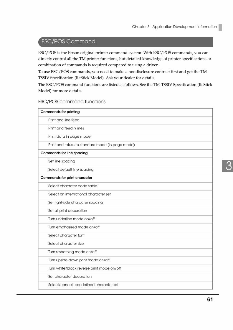
ESC/POS Command
ESC/POS is the Epson original printer command system. With ESC/POS commands, you can directly control all the TM printer functions, but detailed knowledge of printer specifications or combination of commands is required compared to using a driver.
To use ESC/POS commands, you need to make a nondisclosure contract first and get the TM-T88IV Specification (ReStick Model). Ask your dealer for details.
The ESC/POS command functions are listed as follows. See the TM-T88IV Specification (ReStick Model) for more details.
ESC/POS command functions
Commands for printing
Print and line feed
Print and feed n lines
Print data in page mode
Print and return to standard mode (in page mode)
Commands for line spacing
Set line spacing
Select default line spacing
Commands for print character
Select character code table
Select an international character set
Set right-side character spacing
Set all print decoration
Turn underline mode on/off
Turn emphasized mode on/off
Select character font
Select character size
Turn smoothing mode on/off
Turn upside-down print mode on/off
Turn white/black reverse print mode on/off
Set character decoration
Select/cancel user-defined character set
62
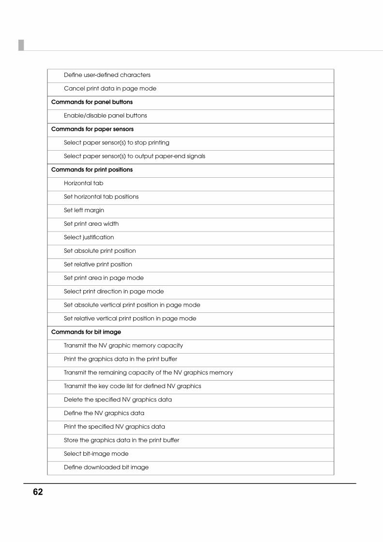
Define user-defined characters
Cancel print data in page mode
Commands for panel buttons
Enable/disable panel buttons
Commands for paper sensors
Select paper sensor(s) to stop printing
Select paper sensor(s) to output paper-end signals
Commands for print positions
Horizontal tab
Set horizontal tab positions
Set left margin
Set print area width
Select justification
Set absolute print position
Set relative print position
Set print area in page mode
Select print direction in page mode
Set absolute vertical print position in page mode
Set relative vertical print position in page mode
Commands for bit image
Transmit the NV graphic memory capacity
Print the graphics data in the print buffer
Transmit the remaining capacity of the NV graphics memory
Transmit the key code list for defined NV graphics
Delete the specified NV graphics data
Define the NV graphics data
Print the specified NV graphics data
Store the graphics data in the print buffer
Select bit-image mode
Define downloaded bit image
Chapter 3 Application Development Information
63
3
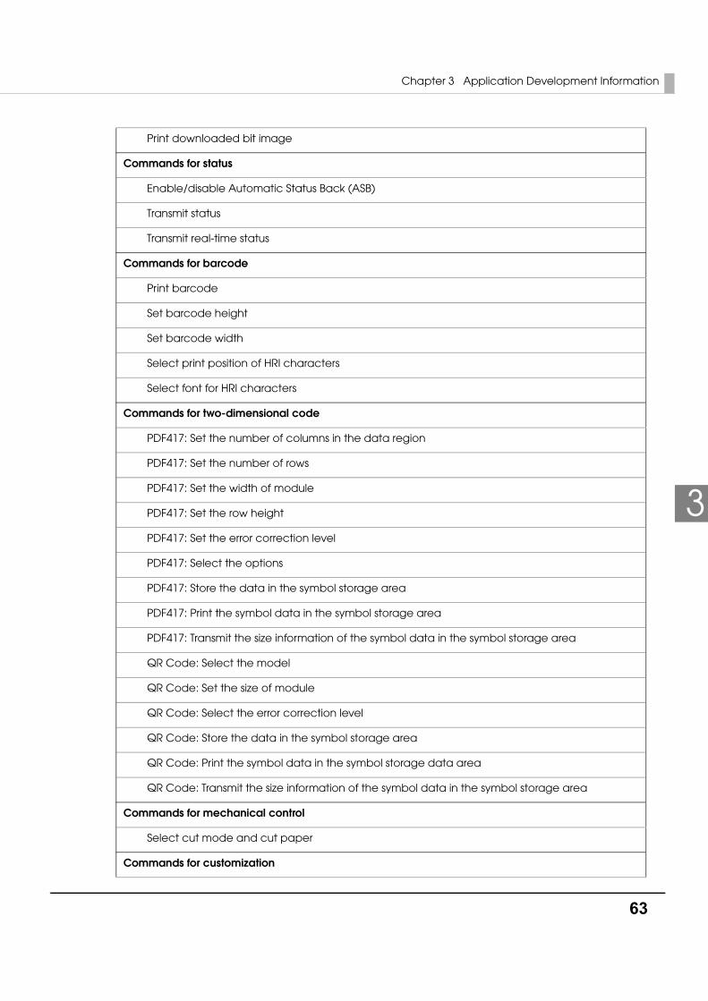
Print downloaded bit image
Commands for status
Enable/disable Automatic Status Back (ASB)
Transmit status
Transmit real-time status
Commands for barcode
Print barcode
Set barcode height
Set barcode width
Select print position of HRI characters
Select font for HRI characters
Commands for two-dimensional code
PDF417: Set the number of columns in the data region
PDF417: Set the number of rows
PDF417: Set the width of module
PDF417: Set the row height
PDF417: Set the error correction level
PDF417: Select the options
PDF417: Store the data in the symbol storage area
PDF417: Print the symbol data in the symbol storage area
PDF417: Transmit the size information of the symbol data in the symbol storage area
QR Code: Select the model
QR Code: Set the size of module
QR Code: Select the error correction level
QR Code: Store the data in the symbol storage area
QR Code: Print the symbol data in the symbol storage data area
QR Code: Transmit the size information of the symbol data in the symbol storage area
Commands for mechanical control
Select cut mode and cut paper
Commands for customization
64
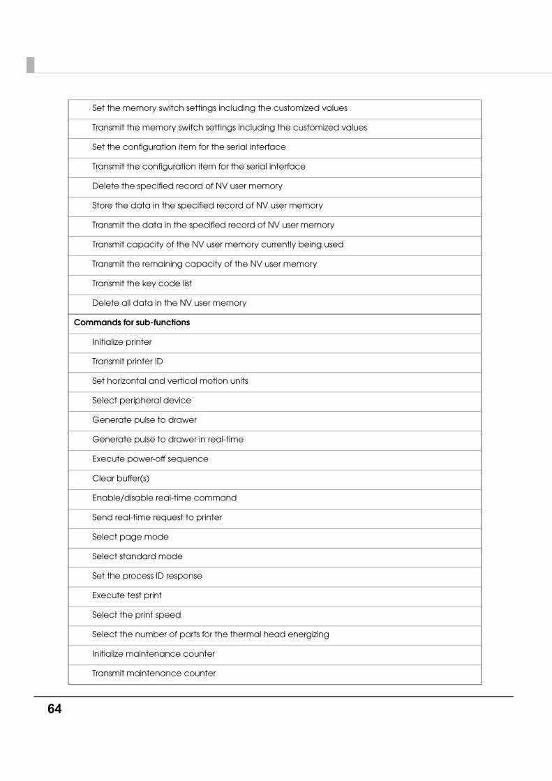
Set the memory switch settings including the customized values
Transmit the memory switch settings including the customized values
Set the configuration item for the serial interface
Transmit the configuration item for the serial interface
Delete the specified record of NV user memory
Store the data in the specified record of NV user memory
Transmit the data in the specified record of NV user memory
Transmit capacity of the NV user memory currently being used
Transmit the remaining capacity of the NV user memory
Transmit the key code list
Delete all data in the NV user memory
Commands for sub-functions
Initialize printer
Transmit printer ID
Set horizontal and vertical motion units
Select peripheral device
Generate pulse to drawer
Generate pulse to drawer in real-time
Execute power-off sequence
Clear buffer(s)
Enable/disable real-time command
Send real-time request to printer
Select page mode
Select standard mode
Set the process ID response
Execute test print
Select the print speed
Select the number of parts for the thermal head energizing
Initialize maintenance counter
Transmit maintenance counter
Chapter 3 Application Development Information
65
3
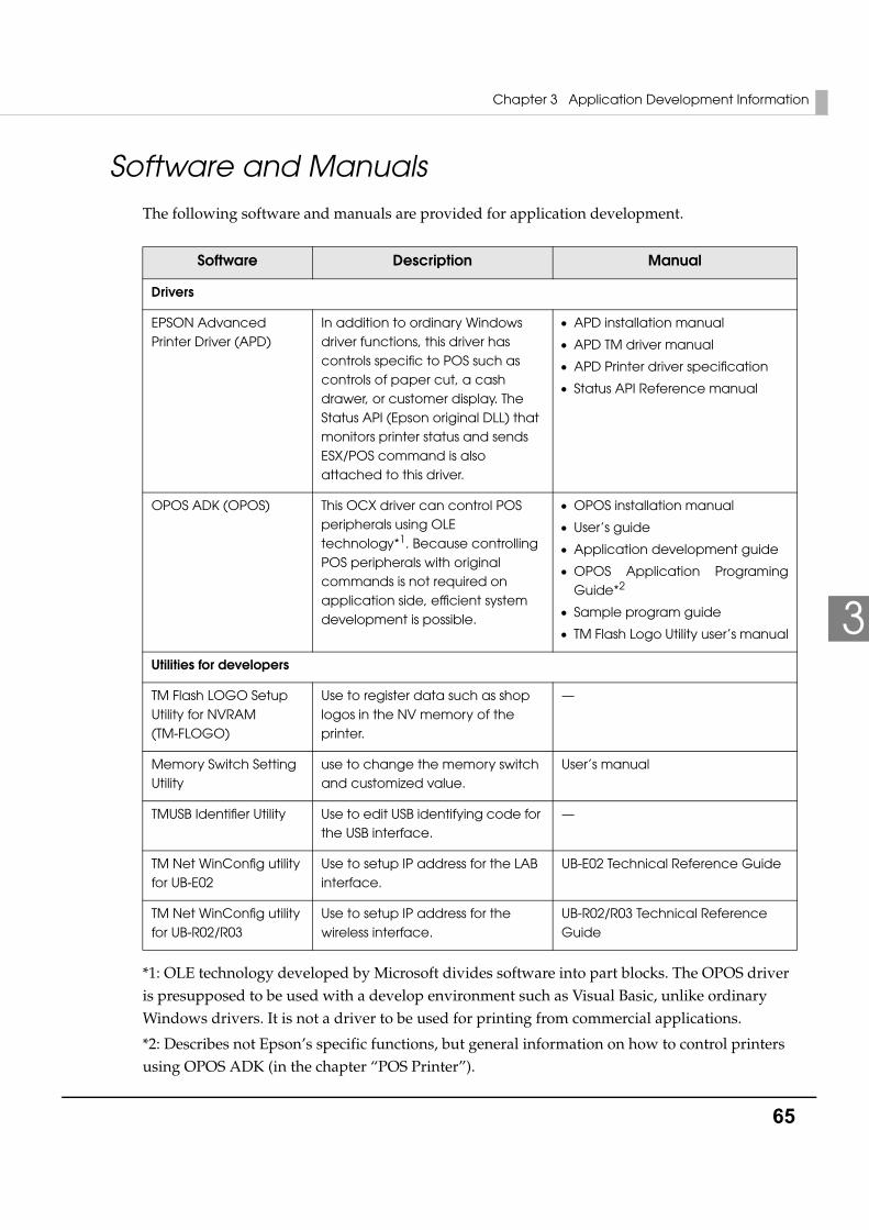
Software and ManualsThe following software and manuals are provided for application development.
*1: OLE technology developed by Microsoft divides software into part blocks. The OPOS driver is presupposed to be used with a develop environment such as Visual Basic, unlike ordinary Windows drivers. It is not a driver to be used for printing from commercial applications.
*2: Describes not Epson’s specific functions, but general information on how to control printers using OPOS ADK (in the chapter “POS Printer”).
Software Description Manual
Drivers
EPSON Advanced Printer Driver (APD)
In addition to ordinary Windows driver functions, this driver has controls specific to POS such as controls of paper cut, a cash drawer, or customer display. The Status API (Epson original DLL) that monitors printer status and sends ESX/POS command is also attached to this driver.
• APD installation manual
• APD TM driver manual
• APD Printer driver specification
• Status API Reference manual
OPOS ADK (OPOS) This OCX driver can control POS peripherals using OLE technology*1. Because controlling POS peripherals with original commands is not required on application side, efficient system development is possible.
• OPOS installation manual
• User’s guide
• Application development guide
• OPOS Application Programing Guide*2
• Sample program guide
• TM Flash Logo Utility user’s manual
Utilities for developers
TM Flash LOGO Setup Utility for NVRAM (TM-FLOGO)
Use to register data such as shop logos in the NV memory of the printer.
—
Memory Switch Setting Utility
use to change the memory switch and customized value.
User’s manual
TMUSB Identifier Utility Use to edit USB identifying code for the USB interface.
—
TM Net WinConfig utility for UB-E02
Use to setup IP address for the LAB interface.
UB-E02 Technical Reference Guide
TM Net WinConfig utility for UB-R02/R03
Use to setup IP address for the wireless interface.
UB-R02/R03 Technical Reference Guide

66
Other than listed in the previous page, UB-E02 Technical Reference Guide is provided to develop applications for the LAN interface.
Download
Drivers, utilities, and manuals can be downloaded from one of the following URLs.
For customers in North America, go to the following web site:
http://www.epsonexpert.com/ and follow the on-screen instructions.
For customers in other countries, go to the following web site:
http://www.epson-pos.com/
Chapter 3 Application Development Information
67
3
Setting Check ModesBesides the ordinary print mode, the printer has a self-test mode and hexadecimal dumping mode to check settings of the printer.
Self-test Mode
You can confirm the following printer functions by running the self-test.
• Control circuit functions
• Printer mechanism
• Print quality
• ROM version
• DIP switch settings
Starting Self-testFollow the steps below to run the self-test.
1 Close the roll paper cover.
2 While pressing the FEED button, turn on the printer. (Keep pressing the FEED button until the printer starts printing.)
The printer prints current status of the printer on the roll paper.
When the printer finishes printing the printer status, the following message is printed and the PAPER OUT LED flashes. (The printer is now in the self-test wait mode.):
“If you want to continue SELF-TEST printing. Please press FEED button.”
3 To begin the print test again, press the FEED button while the printer is in the self-test wait mode.
4 After printing the following message, the printer is initialized and returned to the normal mode.
“*** completed ***“
With the LAN interface, before printing starts, it takes 6 seconds if the IP address is fixed and 13 seconds if the IP address is obtained with the automatic setting. (It may takes longer depending on the response time from a host.)
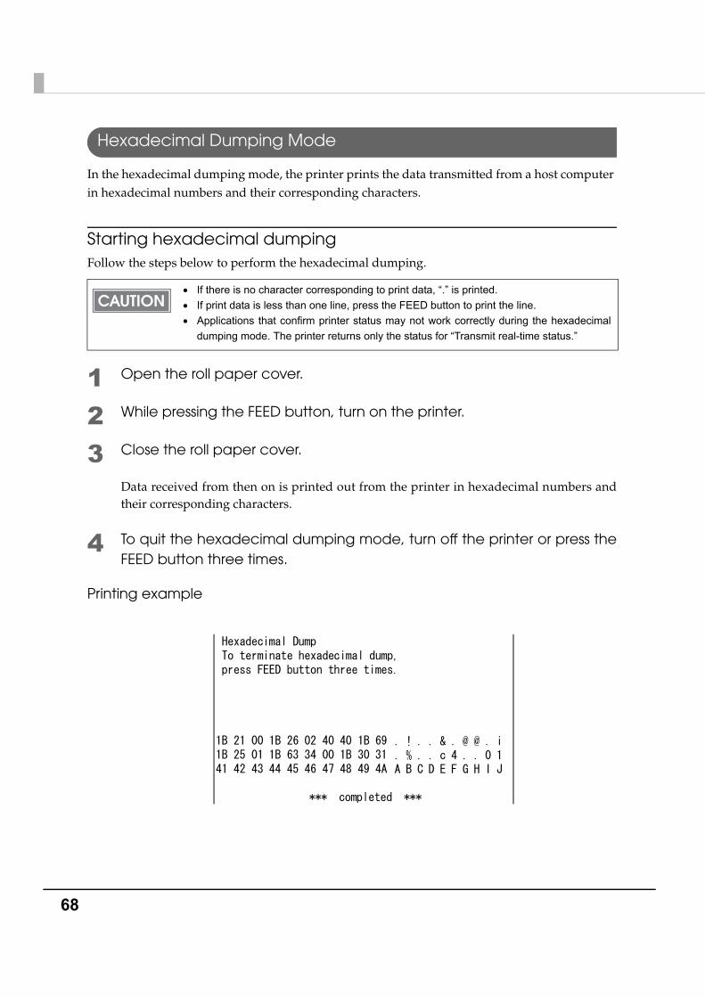
68
Hexadecimal Dumping Mode
In the hexadecimal dumping mode, the printer prints the data transmitted from a host computer in hexadecimal numbers and their corresponding characters.
Starting hexadecimal dumpingFollow the steps below to perform the hexadecimal dumping.
1 Open the roll paper cover.
2 While pressing the FEED button, turn on the printer.
3 Close the roll paper cover.
Data received from then on is printed out from the printer in hexadecimal numbers and their corresponding characters.
4 To quit the hexadecimal dumping mode, turn off the printer or press the FEED button three times.
Printing example
• If there is no character corresponding to print data, “.” is printed.• If print data is less than one line, press the FEED button to print the line.• Applications that confirm printer status may not work correctly during the hexadecimal
dumping mode. The printer returns only the status for “Transmit real-time status.”
Hexadecimal Dump To terminate hexadecimal dump, press FEED button three times. 1B 21 00 1B 26 02 40 40 1B 69 .!..&.@@.i 1B 25 01 1B 63 34 00 1B 30 31 .%..c4..01 41 42 43 44 45 46 47 48 49 4A ABCDEFGHIJ
*** completed ***
. ! . . & . @ @ . i
. % . . c 4 . . 0 1 A B C D E F G H I J
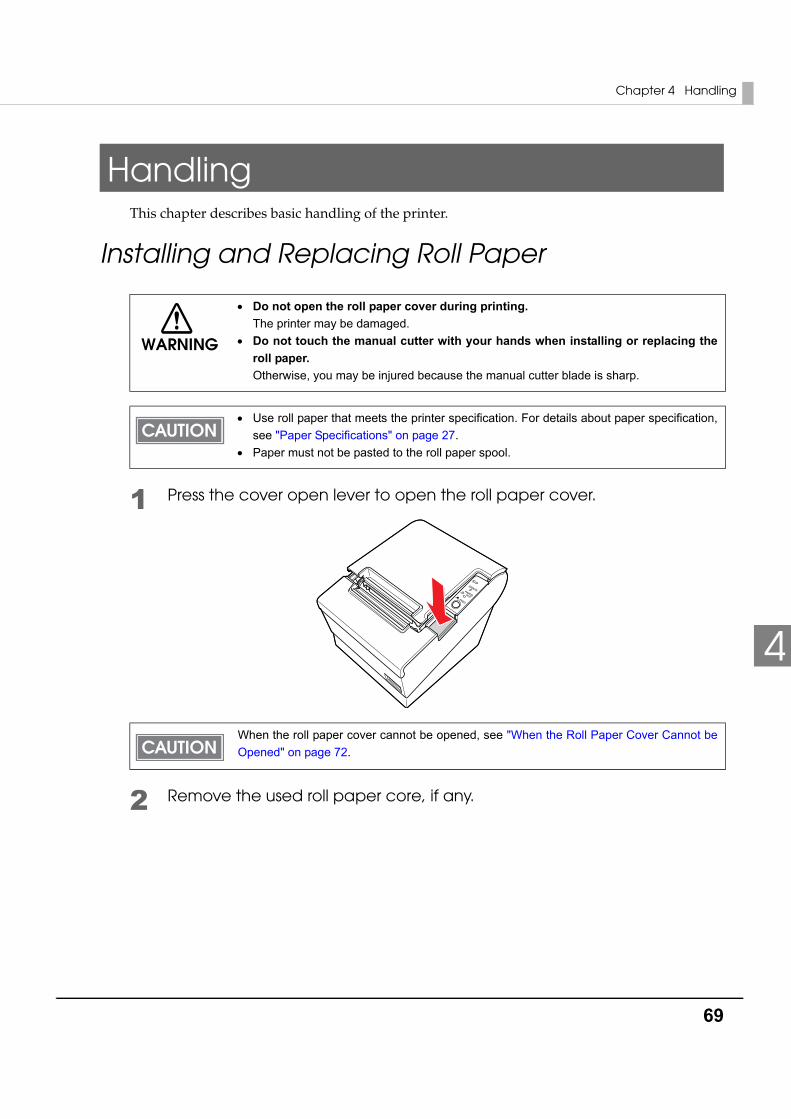
Chapter 4 Handling
69
4
HandlingThis chapter describes basic handling of the printer.
Installing and Replacing Roll Paper
1 Press the cover open lever to open the roll paper cover.
2 Remove the used roll paper core, if any.
WARNING
• Do not open the roll paper cover during printing. The printer may be damaged.
• Do not touch the manual cutter with your hands when installing or replacing the roll paper. Otherwise, you may be injured because the manual cutter blade is sharp.
• Use roll paper that meets the printer specification. For details about paper specification, see "Paper Specifications" on page 27.
• Paper must not be pasted to the roll paper spool.
When the roll paper cover cannot be opened, see "When the Roll Paper Cover Cannot be Opened" on page 72.
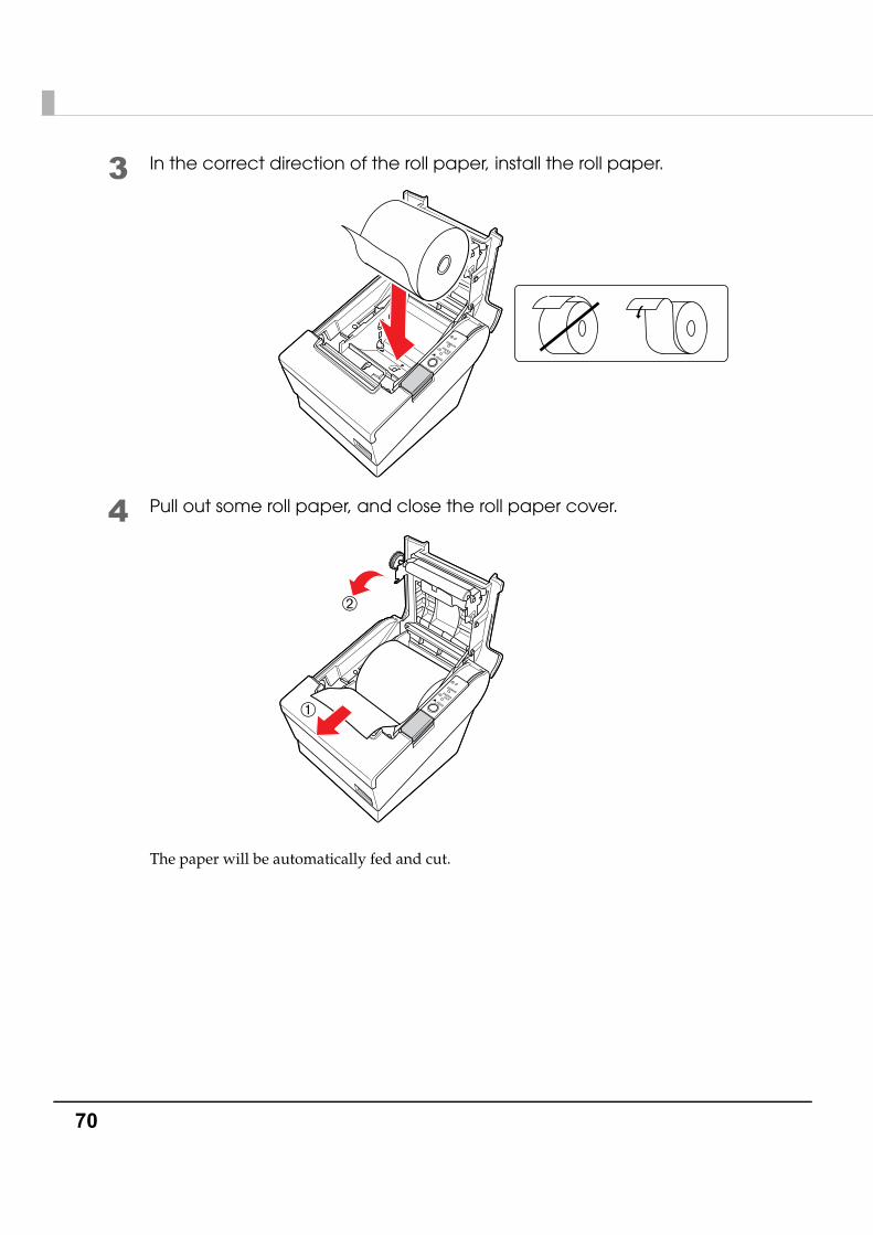
70
3 In the correct direction of the roll paper, install the roll paper.
4 Pull out some roll paper, and close the roll paper cover.
The paper will be automatically fed and cut.
➀
➁
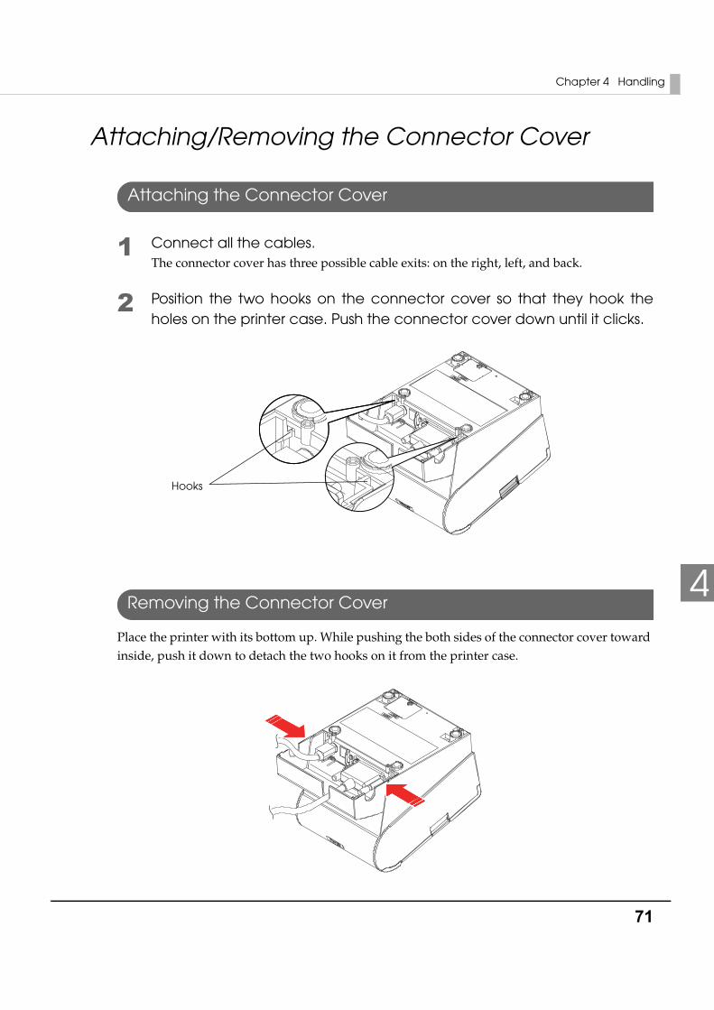
Chapter 4 Handling
71
4
Attaching/Removing the Connector Cover
Attaching the Connector Cover
1 Connect all the cables.The connector cover has three possible cable exits: on the right, left, and back.
2 Position the two hooks on the connector cover so that they hook the holes on the printer case. Push the connector cover down until it clicks.
Removing the Connector Cover
Place the printer with its bottom up. While pushing the both sides of the connector cover toward inside, push it down to detach the two hooks on it from the printer case.
Hooks
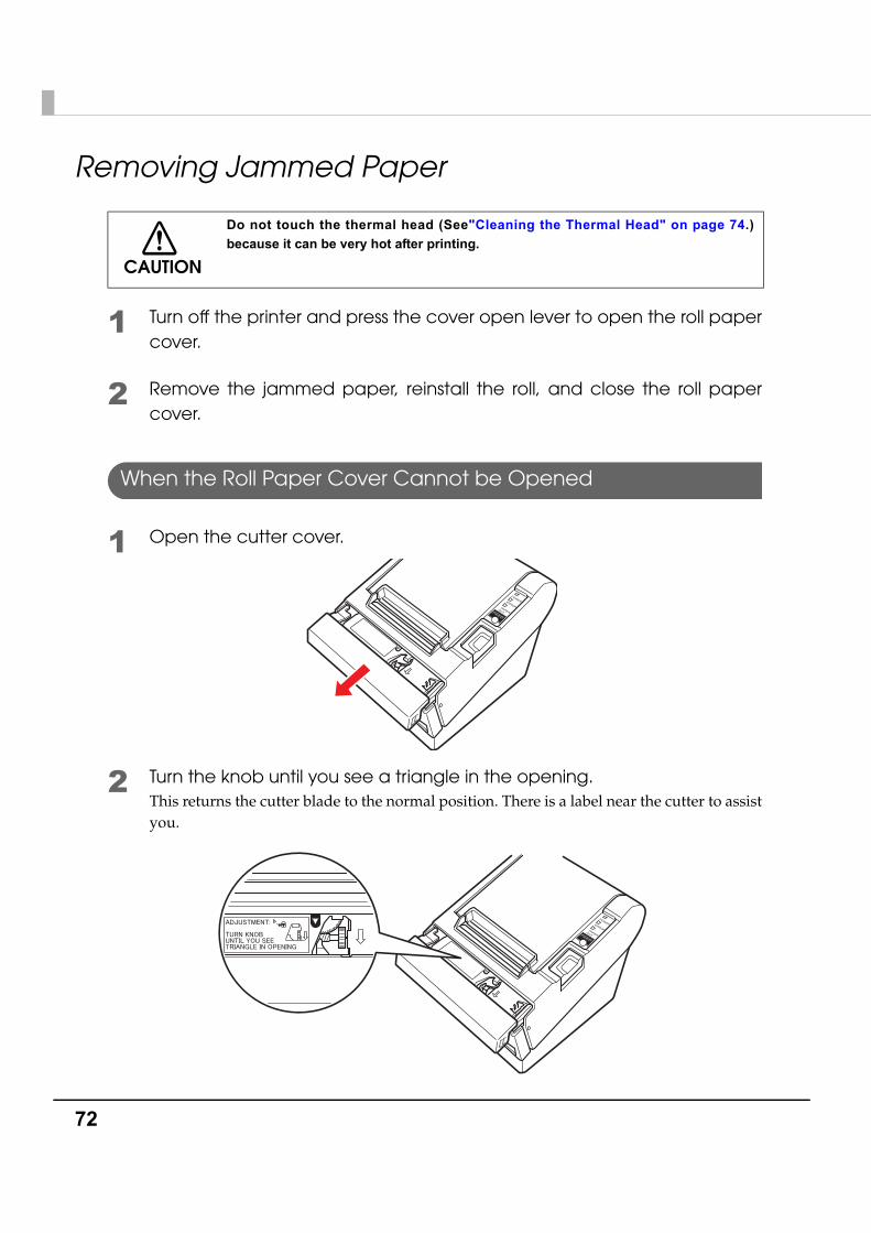
72
Removing Jammed Paper
1 Turn off the printer and press the cover open lever to open the roll paper cover.
2 Remove the jammed paper, reinstall the roll, and close the roll paper cover.
When the Roll Paper Cover Cannot be Opened
1 Open the cutter cover.
2 Turn the knob until you see a triangle in the opening.This returns the cutter blade to the normal position. There is a label near the cutter to assist you.
CAUTION
Do not touch the thermal head (See"Cleaning the Thermal Head" on page 74.) because it can be very hot after printing.

Chapter 4 Handling
73
4
3 Close the cutter cover.
4 Open the roll paper cover and remove the jammed paper.
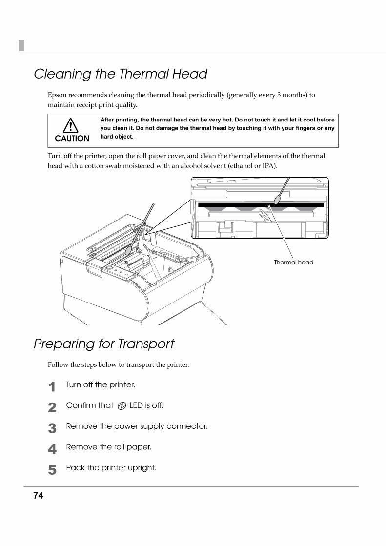
74
Cleaning the Thermal HeadEpson recommends cleaning the thermal head periodically (generally every 3 months) to maintain receipt print quality.
Turn off the printer, open the roll paper cover, and clean the thermal elements of the thermal head with a cotton swab moistened with an alcohol solvent (ethanol or IPA).
Preparing for TransportFollow the steps below to transport the printer.
1 Turn off the printer.
2 Confirm that LED is off.
3 Remove the power supply connector.
4 Remove the roll paper.
5 Pack the printer upright.
CAUTION
After printing, the thermal head can be very hot. Do not touch it and let it cool before you clean it. Do not damage the thermal head by touching it with your fingers or any hard object.
Thermal head
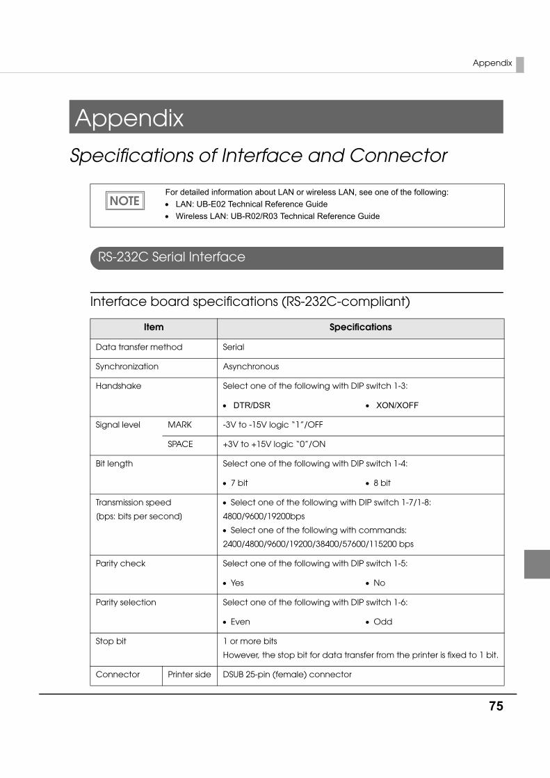
Appendix
75
Appendix
Specifications of Interface and Connector
RS-232C Serial Interface
Interface board specifications (RS-232C-compliant)
For detailed information about LAN or wireless LAN, see one of the following:• LAN: UB-E02 Technical Reference Guide• Wireless LAN: UB-R02/R03 Technical Reference Guide
Item Specifications
Data transfer method Serial
Synchronization Asynchronous
Handshake Select one of the following with DIP switch 1-3:
• DTR/DSR • XON/XOFF
Signal level MARK -3V to -15V logic “1”/OFF
SPACE +3V to +15V logic “0”/ON
Bit length Select one of the following with DIP switch 1-4:
• 7 bit • 8 bit
Transmission speed
[bps: bits per second]
• Select one of the following with DIP switch 1-7/1-8:
4800/9600/19200bps
• Select one of the following with commands:
2400/4800/9600/19200/38400/57600/115200 bps
Parity check Select one of the following with DIP switch 1-5:
• Yes • No
Parity selection Select one of the following with DIP switch 1-6:
• Even • Odd
Stop bit 1 or more bits
However, the stop bit for data transfer from the printer is fixed to 1 bit.
Connector Printer side DSUB 25-pin (female) connector
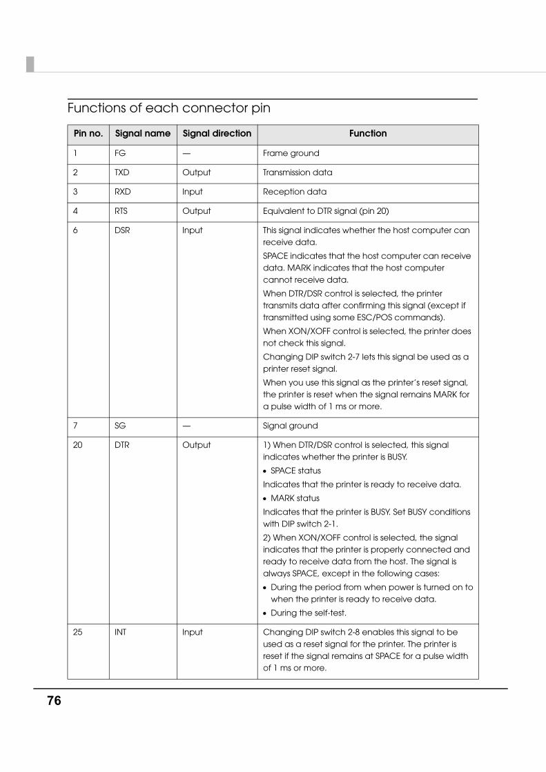
76
Functions of each connector pin
Pin no. Signal name Signal direction Function
1 FG — Frame ground
2 TXD Output Transmission data
3 RXD Input Reception data
4 RTS Output Equivalent to DTR signal (pin 20)
6 DSR Input This signal indicates whether the host computer can receive data.
SPACE indicates that the host computer can receive data. MARK indicates that the host computer cannot receive data.
When DTR/DSR control is selected, the printer transmits data after confirming this signal (except if transmitted using some ESC/POS commands).
When XON/XOFF control is selected, the printer does not check this signal.
Changing DIP switch 2-7 lets this signal be used as a printer reset signal.
When you use this signal as the printer’s reset signal, the printer is reset when the signal remains MARK for a pulse width of 1 ms or more.
7 SG — Signal ground
20 DTR Output 1) When DTR/DSR control is selected, this signal indicates whether the printer is BUSY.
• SPACE status
Indicates that the printer is ready to receive data.
• MARK status
Indicates that the printer is BUSY. Set BUSY conditions with DIP switch 2-1.
2) When XON/XOFF control is selected, the signal indicates that the printer is properly connected and ready to receive data from the host. The signal is always SPACE, except in the following cases:
• During the period from when power is turned on to when the printer is ready to receive data.
• During the self-test.
25 INT Input Changing DIP switch 2-8 enables this signal to be used as a reset signal for the printer. The printer is reset if the signal remains at SPACE for a pulse width of 1 ms or more.
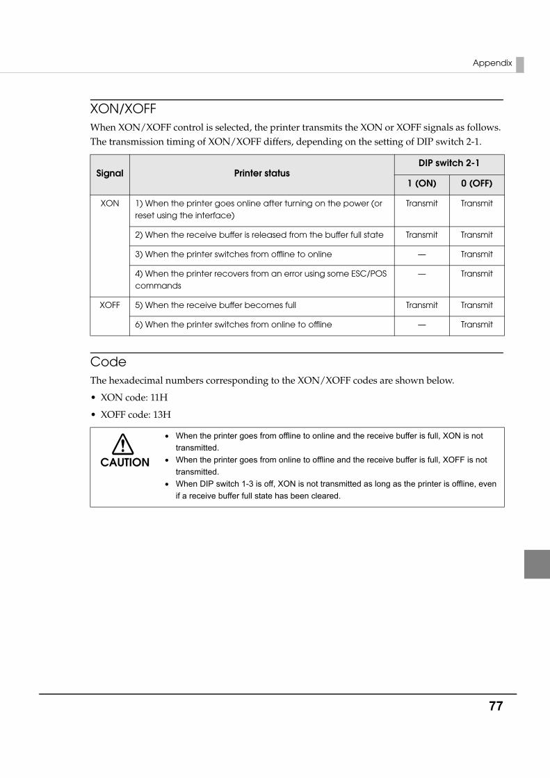
Appendix
77
XON/XOFFWhen XON/XOFF control is selected, the printer transmits the XON or XOFF signals as follows. The transmission timing of XON/XOFF differs, depending on the setting of DIP switch 2-1.
CodeThe hexadecimal numbers corresponding to the XON/XOFF codes are shown below.
• XON code: 11H
• XOFF code: 13H
Signal Printer statusDIP switch 2-1
1 (ON) 0 (OFF)
XON 1) When the printer goes online after turning on the power (or reset using the interface)
Transmit Transmit
2) When the receive buffer is released from the buffer full state Transmit Transmit
3) When the printer switches from offline to online — Transmit
4) When the printer recovers from an error using some ESC/POS commands
— Transmit
XOFF 5) When the receive buffer becomes full Transmit Transmit
6) When the printer switches from online to offline — Transmit
CAUTION
• When the printer goes from offline to online and the receive buffer is full, XON is not transmitted.
• When the printer goes from online to offline and the receive buffer is full, XOFF is not transmitted.
• When DIP switch 1-3 is off, XON is not transmitted as long as the printer is offline, even if a receive buffer full state has been cleared.
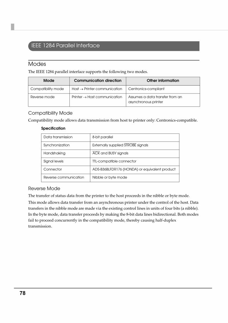
78
IEEE 1284 Parallel Interface
ModesThe IEEE 1284 parallel interface supports the following two modes.
Compatibility Mode
Compatibility mode allows data transmission from host to printer only: Centronics-compatible.
Specification
Reverse Mode
The transfer of status data from the printer to the host proceeds in the nibble or byte mode.
This mode allows data transfer from an asynchronous printer under the control of the host. Data transfers in the nibble mode are made via the existing control lines in units of four bits (a nibble). In the byte mode, data transfer proceeds by making the 8-bit data lines bidirectional. Both modes fail to proceed concurrently in the compatibility mode, thereby causing half-duplex transmission.
Mode Communication direction Other information
Compatibility mode Host → Printer communication Centronics-compliant
Reverse mode Printer → Host communication Assumes a data transfer from an asynchronous printer
Data transmission 8-bit parallel
Synchronization Externally supplied STROBE signals
Handshaking ACK and BUSY signals
Signal levels TTL-compatible connector
Connector ADS-B36BLFDR176 (HONDA) or equivalent product
Reverse communication Nibble or byte mode
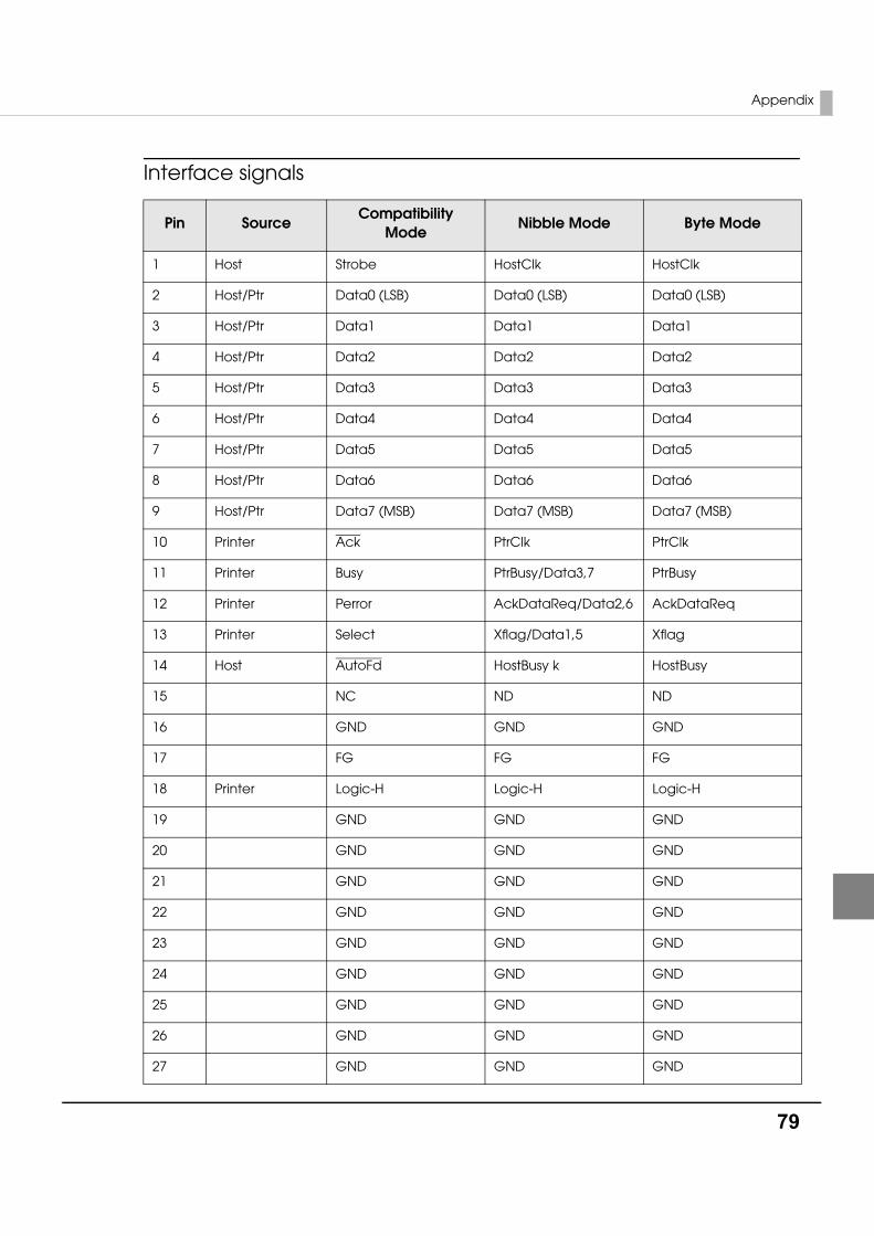
Appendix
79
Interface signals
Pin SourceCompatibility
ModeNibble Mode Byte Mode
1 Host Strobe HostClk HostClk
2 Host/Ptr Data0 (LSB) Data0 (LSB) Data0 (LSB)
3 Host/Ptr Data1 Data1 Data1
4 Host/Ptr Data2 Data2 Data2
5 Host/Ptr Data3 Data3 Data3
6 Host/Ptr Data4 Data4 Data4
7 Host/Ptr Data5 Data5 Data5
8 Host/Ptr Data6 Data6 Data6
9 Host/Ptr Data7 (MSB) Data7 (MSB) Data7 (MSB)
10 Printer Ack PtrClk PtrClk
11 Printer Busy PtrBusy/Data3,7 PtrBusy
12 Printer Perror AckDataReq/Data2,6 AckDataReq
13 Printer Select Xflag/Data1,5 Xflag
14 Host AutoFd HostBusy k HostBusy
15 NC ND ND
16 GND GND GND
17 FG FG FG
18 Printer Logic-H Logic-H Logic-H
19 GND GND GND
20 GND GND GND
21 GND GND GND
22 GND GND GND
23 GND GND GND
24 GND GND GND
25 GND GND GND
26 GND GND GND
27 GND GND GND
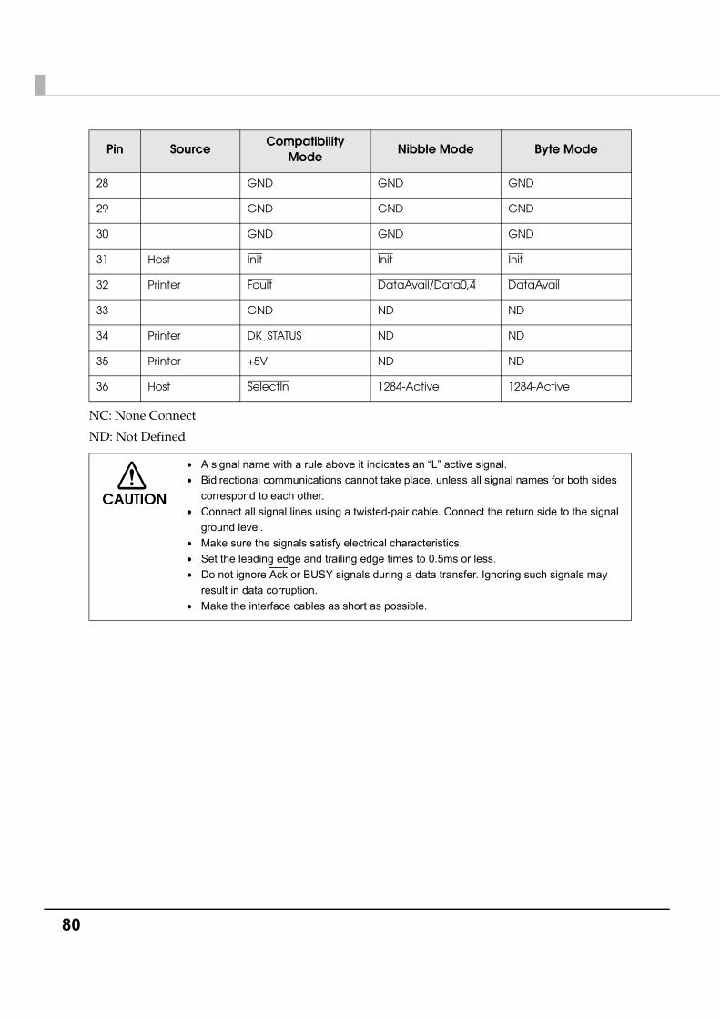
80
NC: None Connect
ND: Not Defined
28 GND GND GND
29 GND GND GND
30 GND GND GND
31 Host Init Init Init
32 Printer Fault DataAvail/Data0,4 DataAvail
33 GND ND ND
34 Printer DK_STATUS ND ND
35 Printer +5V ND ND
36 Host SelectIn 1284-Active 1284-Active
CAUTION
• A signal name with a rule above it indicates an “L” active signal.• Bidirectional communications cannot take place, unless all signal names for both sides
correspond to each other.• Connect all signal lines using a twisted-pair cable. Connect the return side to the signal
ground level.• Make sure the signals satisfy electrical characteristics.• Set the leading edge and trailing edge times to 0.5ms or less.• Do not ignore Ack or BUSY signals during a data transfer. Ignoring such signals may
result in data corruption.• Make the interface cables as short as possible.
Pin SourceCompatibility
ModeNibble Mode Byte Mode
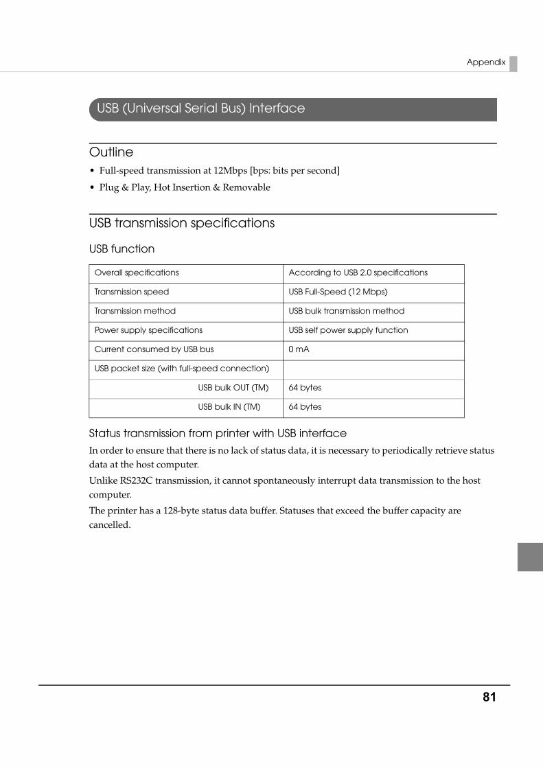
Appendix
81
USB (Universal Serial Bus) Interface
Outline• Full-speed transmission at 12Mbps [bps: bits per second]
• Plug & Play, Hot Insertion & Removable
USB transmission specifications
USB function
Status transmission from printer with USB interface
In order to ensure that there is no lack of status data, it is necessary to periodically retrieve status data at the host computer.
Unlike RS232C transmission, it cannot spontaneously interrupt data transmission to the host computer.
The printer has a 128-byte status data buffer. Statuses that exceed the buffer capacity are cancelled.
Overall specifications According to USB 2.0 specifications
Transmission speed USB Full-Speed (12 Mbps)
Transmission method USB bulk transmission method
Power supply specifications USB self power supply function
Current consumed by USB bus 0 mA
USB packet size (with full-speed connection)
USB bulk OUT (TM) 64 bytes
USB bulk IN (TM) 64 bytes
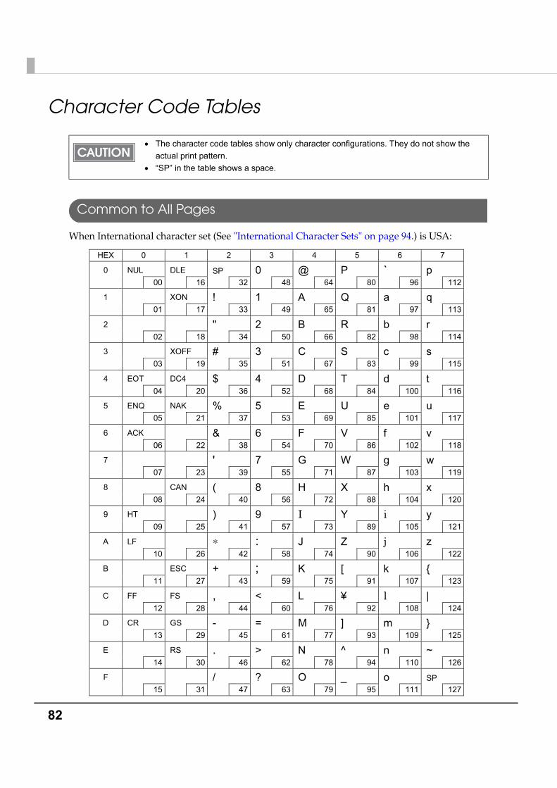
82
Character Code Tables
Common to All Pages
When International character set (See "International Character Sets" on page 94.) is USA:
• The character code tables show only character configurations. They do not show the actual print pattern.
• “SP” in the table shows a space.
HEX 0 1 2 3 4 5 6 7
0 NUL DLE 00 16
SP 32
0 48
@ 64
P 80
` 96
p 112
1 XON 01 17
! 33
1 49
A 65
Q 81
a 97
q 113
2 02 18
" 34
2 50
B 66
R 82
b 98
r 114
3 XOFF 03 19
# 35
3 51
C 67
S 83
c 99
s 115
4 EOT DC4 04 20
$ 36
4 52
D 68
T 84
d 100
t 116
5 ENQ NAK 05 21
% 37
5 53
E 69
U 85
e 101
u 117
6 ACK 06 22
& 38
6 54
F 70
V 86
f 102
v 118
7 07 23
' 39
7 55
G 71
W 87
g 103
w 119
8 CAN 08 24
( 40
8 56
H 72
X 88
h 104
x 120
9 HT 09 25
) 41
9 57
I 73
Y 89
i 105
y 121
A LF 10 26
∗ 42
: 58
J 74
Z 90
j 106
z 122
B ESC 11 27
+ 43
; 59
K 75
[ 91
k 107
{ 123
C FF FS 12 28
, 44
< 60
L 76
¥ 92
l 108
| 124
D CR GS 13 29
- 45
= 61
M 77
] 93
m 109
} 125
E RS 14 30
. 46
> 62
N 78
^ 94
n 110
~ 126
F 15 31
/ 47
? 63
O 79
_ 95
o 111
SP 127

Appendix
83
Page 0 [PC437: USA, Standard Europe]
HEX 8 9 A B C D E F
0
Ç 128
É 144
á 160
░ 176
└ 192
╨ 208
α 224
≡ 240
1
ü 129
æ 145
í 161
▒ 177
┴ 193
╤ 209
β 225
± 241
2
é 130
Æ 146
ó 162
▓ 178
┬ 194
╥ 210
Γ 226
≥ 242
3
â 131
ô 147
ú 163
│ 179
├ 195
╙ 211
π 227
≤ 243
4
ä 132
ö 148
ñ 164
┤ 180
─ 196
╘ 212
Σ 228
⌠ 244
5
à 133
ò 149
Ñ 165
╡ 181
┼ 197
╒ 213
σ 229
⌡ 245
6
å 134
û 150
a 166
╢ 182
╞ 198
╓ 214
μ 230
÷ 246
7
ç 135
ù 151
o 167
╖ 183
╟ 199
╫ 215
τ 231
≈ 247
8
ê 136
ÿ 152
¿ 168
╕ 184
╚ 200
╪ 216
Ф 232
° 248
9
ë 137
Ö 153
┌ 169
╣ 185
╔ 201
┘ 217
Θ 233
• 249
A
è 138
Ü 154
¬ 170
║ 186
╩ 202
┌ 218
Ω 234
· 250
B
ï 139
¢ 155
½ 171
╗ 187
╦ 203
█ 219
δ 235
√ 251
C
î 140
£ 156
¼ 172
╝ 188
╠ 204
▄ 220
∞ 236
n 252
D
ì 141
¥ 157
¡ 173
╜ 189
═ 205
▌ 221
Φ 237
² 253
E
Ä 142
Pt 158
« 174
╛ 190
╬ 206
▐ 222
ε 238
■ 254
F
Å 143
ƒ 159
» 175
┐ 191
╧ 207
▀ 223
∩ 239
SP 255
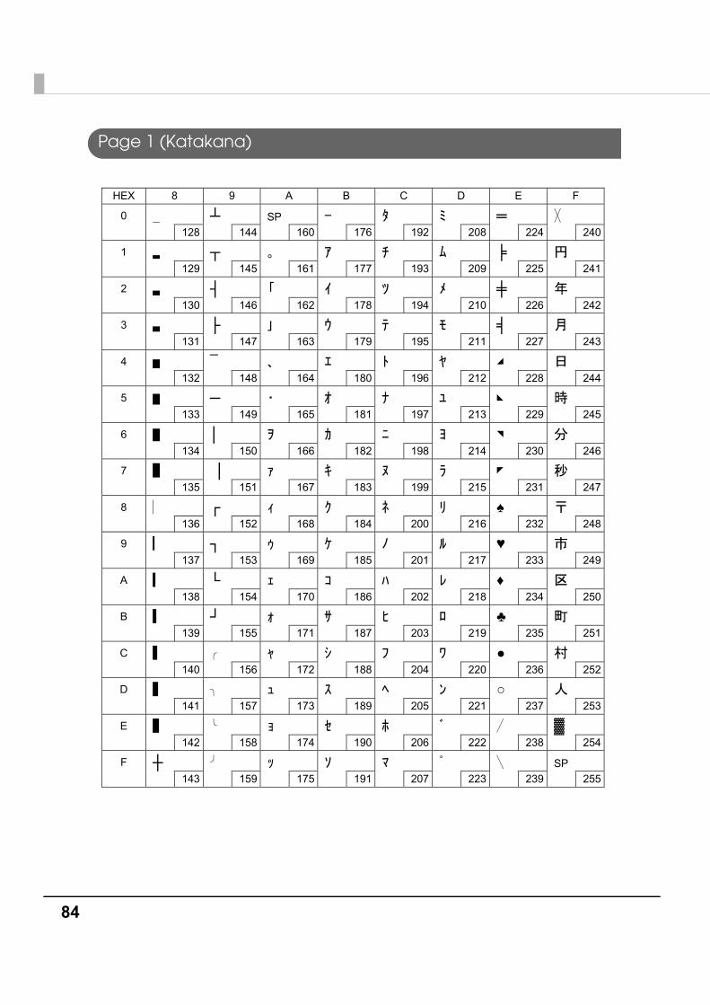
84
Page 1 (Katakana)
HEX 8 9 A B C D E F
0
128
┴ 144
SP 160 176
192
208
═ 224
240
1
129
┬ 145
161 177
193
209
╞ 225
241
2
130
┤ 146
162 178
194
210
╪ 226
242
3
131
├ 147
163 179
195
211
╡ 227
243
4
132
¯ 148
164 180
196
212
228
244
5
133
─ 149
165 181
197
213
229
245
6
134
│ 150
166 182
198
214
230
246
7
135
│ 151
167 183
199
215
231
247
8
136
┌ 152
168 184
200
216
♠ 232
248
9
137
┐ 153
169 185
201
217
♥ 233
249
A
138
└ 154
170 186
202
218
♦ 234
250
B
139
┘ 155
171 187
203
219
♣ 235
251
C
140
156
172 188
204
220
● 236
252
D
141
157
173 189
205
221
○ 237
253
E
142
158
174 190
206
222 238
▓ 254
F
┼ 143
159
175 191
207
223
239
SP 255

Appendix
85
Page 2 (PC850: Multilingual)
HEX 8 9 A B C D E F
0
Ç 128
É 144
á 160
░ 176
└ 192
ð 208
Ó 224
- 240
1
ü 129
æ 145
í 161
▒ 177
┴ 193
Ð 209
β 225
± 241
2
é 130
Æ 146
ó 162
▓ 178
┬ 194
Ê 210
Ô 226
242
3
â 131
ô 147
ú 163
│ 179
├ 195
Ë 211
Ò 227
¾ 243
4
ä 132
ö 148
ñ 164
┤ 180
─ 196
È 212
õ 228
¶ 244
5
à 133
ò 149
Ñ 165
Á 181
┼ 197
ı 213
Õ 229
§ 245
6
å 134
û 150
a 166
 182
ã 198
Í 214
μ 230
÷ 246
7
ç 135
ù 151
o 167
À 183
à 199
Î 215
þ 231
¸ 247
8
ê 136
ÿ 152
¿ 168
© 184
╚ 200
Ï 216
Þ 232
° 248
9
ë 137
Ö 153
® 169
╣ 185
╔ 201
┘ 217
Ú 233
¨ 249
A
è 138
Ü 154
¬ 170
║ 186
╩ 202
┌ 218
Û 234
· 250
B
ï 139
ø 155
½ 171
╗ 187
╦ 203
█ 219
Ù 235
¹ 251
C
î 140
£ 156
¼ 172
╝ 188
╠ 204
▄ 220
ý 236
³ 252
D
ì 141
Ø 157
¡ 173
¢ 189
═ 205
¦ 221
Ý 237
² 253
E
Ä 142
× 158
« 174
¥ 190
╬ 206
Ì 222
¯ 238
■ 254
F
Å 143
ƒ 159
» 175
┐ 191
¤ 207
▀ 223
´ 239
SP 255
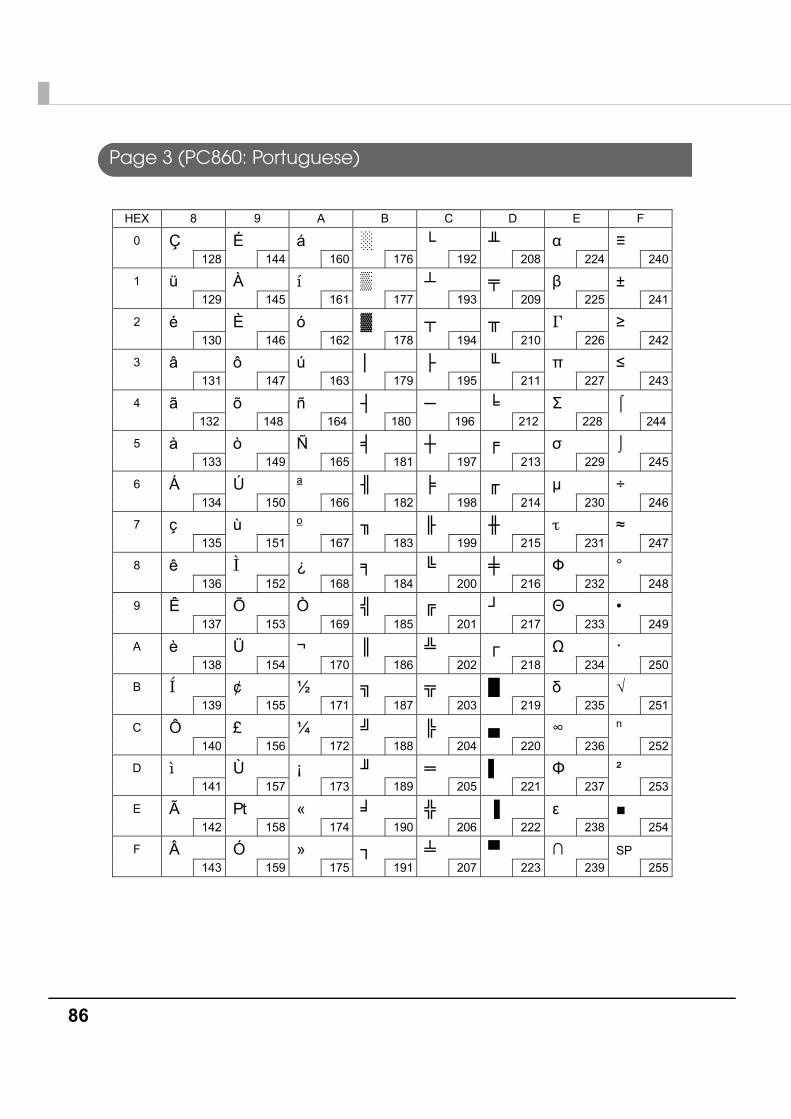
86
Page 3 (PC860: Portuguese)
HEX 8 9 A B C D E F
0
Ç 128
É 144
á 160
░ 176
└ 192
╨ 208
α 224
≡ 240
1
ü 129
À 145
í 161
▒ 177
┴ 193
╤ 209
β 225
± 241
2
é 130
È 146
ó 162
▓ 178
┬ 194
╥ 210
Γ 226
≥ 242
3
â 131
ô 147
ú 163
│ 179
├ 195
╙ 211
π 227
≤ 243
4
ã 132
õ 148
ñ 164
┤ 180
─ 196
╘ 212
Σ 228
⌠ 244
5
à 133
ò 149
Ñ 165
╡ 181
┼ 197
╒ 213
σ 229
⌡ 245
6
Á 134
Ú 150
a 166
╢ 182
╞ 198
╓ 214
μ 230
÷ 246
7
ç 135
ù 151
o 167
╖ 183
╟ 199
╫ 215
τ 231
≈ 247
8
ê 136
Ì 152
¿ 168
╕ 184
╚ 200
╪ 216
Ф 232
° 248
9
Ê 137
Õ 153
Ò 169
╣ 185
╔ 201
┘ 217
Θ 233
• 249
A
è 138
Ü 154
¬ 170
║ 186
╩ 202
┌ 218
Ω 234
· 250
B
Í 139
¢ 155
½ 171
╗ 187
╦ 203
█ 219
δ 235
√ 251
C
Ô 140
£ 156
¼ 172
╝ 188
╠ 204
▄ 220
∞ 236
n 252
D
ì 141
Ù 157
¡ 173
╜ 189
═ 205
▌ 221
Φ 237
² 253
E
à 142
Pt 158
« 174
╛ 190
╬ 206
▐ 222
ε 238
■ 254
F
 143
Ó 159
» 175
┐ 191
╧ 207
▀ 223
∩ 239
SP 255
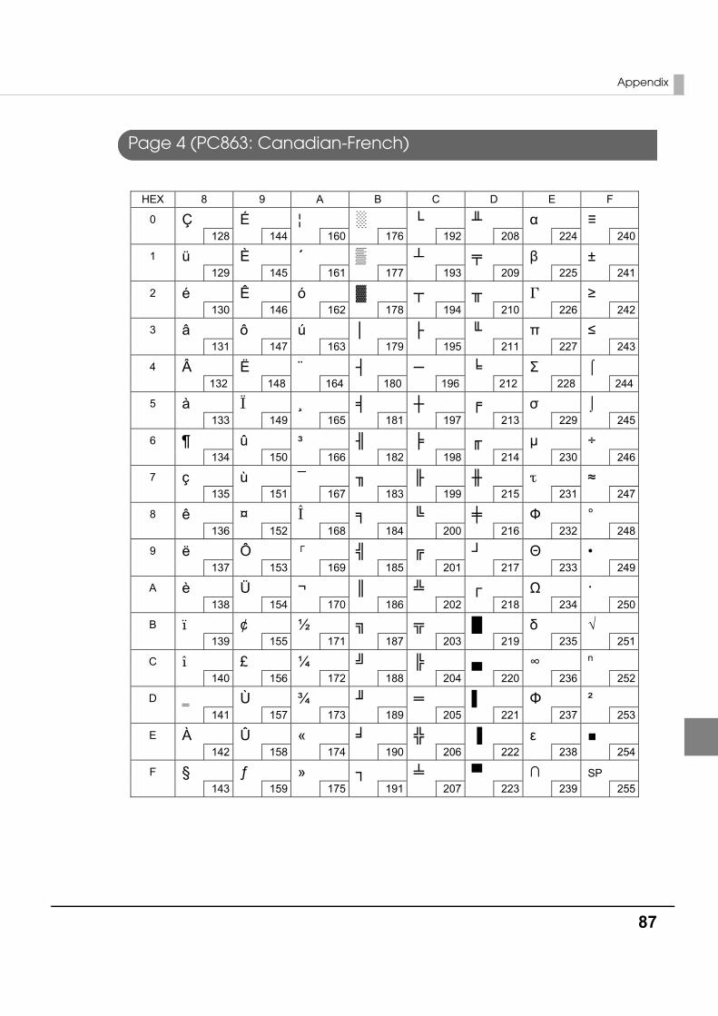
Appendix
87
Page 4 (PC863: Canadian-French)
HEX 8 9 A B C D E F
0
Ç 128
É 144
¦ 160
░ 176
└ 192
╨ 208
α 224
≡ 240
1
ü 129
È 145
´ 161
▒ 177
┴ 193
╤ 209
β 225
± 241
2
é 130
Ê 146
ó 162
▓ 178
┬ 194
╥ 210
Γ 226
≥ 242
3
â 131
ô 147
ú 163
│ 179
├ 195
╙ 211
π 227
≤ 243
4
 132
Ë 148
¨ 164
┤ 180
─ 196
╘ 212
Σ 228
⌠ 244
5
à 133
Ï 149
¸ 165
╡ 181
┼ 197
╒ 213
σ 229
⌡ 245
6
¶ 134
û 150
³ 166
╢ 182
╞ 198
╓ 214
μ 230
÷ 246
7
ç 135
ù 151
¯ 167
╖ 183
╟ 199
╫ 215
τ 231
≈ 247
8
ê 136
¤ 152
Î 168
╕ 184
╚ 200
╪ 216
Ф 232
° 248
9
ë 137
Ô 153
┌ 169
╣ 185
╔ 201
┘ 217
Θ 233
• 249
A
è 138
Ü 154
¬ 170
║ 186
╩ 202
┌ 218
Ω 234
· 250
B
ï 139
¢ 155
½ 171
╗ 187
╦ 203
█ 219
δ 235
√ 251
C
î 140
£ 156
¼ 172
╝ 188
╠ 204
▄ 220
∞ 236
n 252
D
141
Ù 157
¾ 173
╜ 189
═ 205
▌ 221
Φ 237
² 253
E
À 142
Û 158
« 174
╛ 190
╬ 206
▐ 222
ε 238
■ 254
F
§ 143
ƒ 159
» 175
┐ 191
╧ 207
▀ 223
∩ 239
SP 255
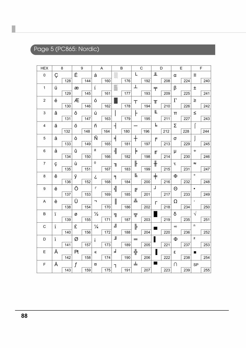
88
Page 5 (PC865: Nordic)
HEX 8 9 A B C D E F
0
Ç 128
É 144
á 160
░ 176
└ 192
╨ 208
α 224
≡ 240
1
ü 129
æ 145
í 161
▒ 177
┴ 193
╤ 209
β 225
± 241
2
é 130
Æ 146
ó 162
▓ 178
┬ 194
╥ 210
Γ 226
≥ 242
3
â 131
ô 147
ú 163
│ 179
├ 195
╙ 211
π 227
≤ 243
4
ä 132
ö 148
ñ 164
┤ 180
─ 196
╘ 212
Σ 228
⌠ 244
5
à 133
ò 149
Ñ 165
╡ 181
┼ 197
╒ 213
σ 229
⌡ 245
6
å 134
û 150
a 166
╢ 182
╞ 198
╓ 214
μ 230
÷ 246
7
ç 135
ù 151
o 167
╖ 183
╟ 199
╫ 215
τ 231
≈ 247
8
ê 136
ÿ 152
¿ 168
╕ 184
╚ 200
╪ 216
Ф 232
° 248
9
ë 137
Ö 153
┌ 169
╣ 185
╔ 201
┘ 217
Θ 233
• 249
A
è 138
Ü 154
¬ 170
║ 186
╩ 202
┌ 218
Ω 234
· 250
B
ï 139
ø 155
½ 171
╗ 187
╦ 203
█ 219
δ 235
√ 251
C
î 140
£ 156
¼ 172
╝ 188
╠ 204
▄ 220
∞ 236
n 252
D
ì 141
Ø 157
¡ 173
╜ 189
═ 205
▌ 221
Φ 237
² 253
E
Ä 142
Pt 158
« 174
╛ 190
╬ 206
▐ 222
ε 238
■ 254
F
Å 143
ƒ 159
¤ 175
┐ 191
╧ 207
▀ 223
∩ 239
SP 255
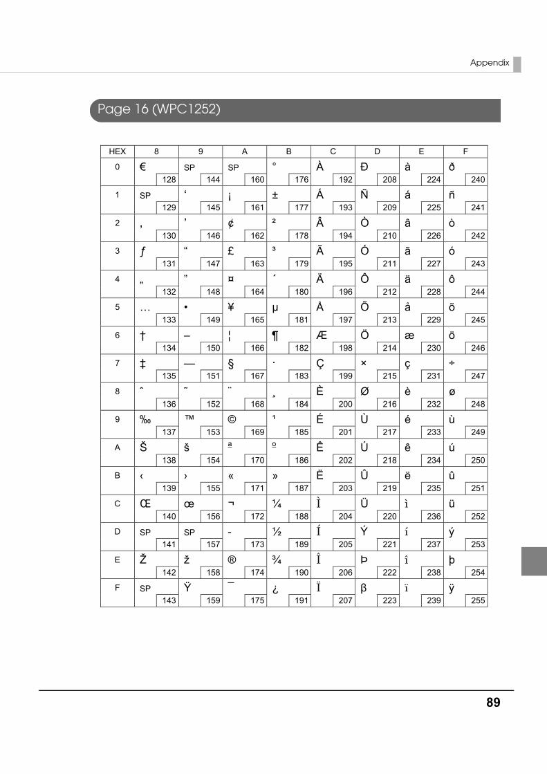
Appendix
89
Page 16 (WPC1252)
HEX 8 9 A B C D E F
0
€ 128
SP 144
SP 160
° 176
À 192
Ð 208
à 224
ð 240
1
SP 129
‘ 145
¡ 161
± 177
Á 193
Ñ 209
á 225
ñ 241
2
‚ 130
’ 146
¢ 162
² 178
 194
Ò 210
â 226
ò 242
3
ƒ 131
“ 147
£ 163
³ 179
à 195
Ó 211
ã 227
ó 243
4
„ 132
” 148
¤ 164
´ 180
Ä 196
Ô 212
ä 228
ô 244
5
… 133
• 149
¥ 165
μ 181
Å 197
Õ 213
å 229
õ 245
6
† 134
– 150
¦ 166
¶ 182
Æ 198
Ö 214
æ 230
ö 246
7
‡ 135
— 151
§ 167
· 183
Ç 199
× 215
ç 231
÷ 247
8
ˆ 136
˜ 152
¨ 168
¸ 184
È 200
Ø 216
è 232
ø 248
9
‰ 137
™ 153
© 169
¹ 185
É 201
Ù 217
é 233
ù 249
A
Š 138
š 154
a
170
o
186 Ê
202 Ú
218 ê
234 ú
250
B
‹ 139
› 155
« 171
» 187
Ë 203
Û 219
ë 235
û 251
C
Π140
œ 156
¬ 172
¼ 188
Ì 204
Ü 220
ì 236
ü 252
D
SP 141
SP 157
173
½ 189
Í 205
Ý 221
í 237
ý 253
E
Ž 142
ž 158
® 174
¾ 190
Î 206
Þ 222
î 238
þ 254
F
SP 143
Ÿ 159
¯ 175
¿ 191
Ï 207
β 223
ï 239
ÿ 255
-
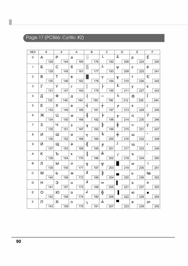
90
Page 17 (PC866: Cyrillic #2)
HEX 8 9 A B C D E F
0
А 128
Р 144
а 160
░ 176
└ 192
╨ 208
р 224
Ё 240
1
Б 129
С 145
б 161
▒ 177
┴ 193
╤ 209
с 225
ё 241
2
В 130
Т 146
в 162
▓ 178
┬ 194
╥ 210
т 226
Є 242
3
Г 131
У 147
г 163
│ 179
├ 195
╙ 211
у 227
є 243
4
Д 132
Ф 148
д 164
┤ 180
─ 196
╘ 212
ф 228
Ї 244
5
Е 133
Х 149
е 165
╡ 181
┼ 197
╒ 213
х 229
ї 245
6
Ж 134
Ц 150
ж 166
╢ 182
╞ 198
╓ 214
ц 230
Ў 246
7
З 135
Ч 151
з 167
╖ 183
╟ 199
╫ 215
ч 231
ў 247
8
И 136
Ш 152
и 168
╕ 184
╚ 200
╪ 216
ш 232
° 248
9
Й 137
Щ 153
й 169
╣ 185
╔ 201
┘ 217
щ 233
• 249
A
К 138
Ъ 154
к 170
║ 186
╩ 202
┌ 218
ъ 234
· 250
B
Л 139
Ы 155
л 171
╗ 187
╦ 203
█ 219
ы 235
√ 251
C
М 140
Ь 156
м 172
╝ 188
╠ 204
▄ 220
ь 236
№ 252
D
Н 141
Э 157
н 173
╜ 189
═ 205
▌ 221
э 237
¤ 253
E
О 142
Ю 158
о 174
╛ 190
╬ 206
▐ 222
ю 238
■ 254
F
П 143
Я 159
п 175
┐ 191
╧ 207
▀ 223
я 239
SP 255
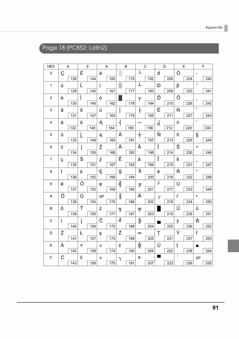
Appendix
91
Page 18 (PC852: Latin2)
HEX 8 9 A B C D E F
0
Ç 128
É 144
á 160
░ 176
└ 192
đ 208
Ó 224
- 240
1
ü 129
Ĺ 145
í 161
▒ 177
┴ 193
Ð 209
β 225
˝ 241
2
é 130
ĺ 146
ó 162
▓ 178
┬ 194
Ď 210
Ô 226
˛ 242
3
â 131
ô 147
ú 163
│ 179
├ 195
Ë 211
Ń 227
ˇ 243
4
ä 132
ö 148
Ą 164
┤ 180
─ 196
d 212
ń 228
˘ 244
5
ů 133
L 149
ą 165
Á 181
┼ 197
Ň 213
ň 229
§ 245
6
ć 134
l 150
Ž 166
 182
Ă 198
Í 214
Š 230
÷ 246
7
ç 135
Ś 151
ž 167
Ě 183
ă 199
Î 215
š 231
¸ 247
8
ł 136
ś 152
Ę 168
Ş 184
╚ 200
ě 216
Ŕ 232
° 248
9
ë 137
Ö 153
ę 169
╣ 185
╔ 201
┘ 217
Ú 233
¨ 249
A
Ő 138
Ü 154
SP 170
║ 186
╩ 202
┌ 218
ŕ 234
• 250
B
ő 139
Ť 155
ź 171
╗ 187
╦ 203
█ 219
Ű 235
ű 251
C
î 140
t 156
Č 172
╝ 188
╠ 204
▄ 220
ý 236
Ř 252
D
Ź 141
Ł 157
ş 173
Ż 189
═ 205
Ţ 221
Ý 237
ř 253
E
Ä 142
× 158
« 174
ż 190
╬ 206
Ů 222
ţ 238
■ 254
F
Ć 143
č 159
» 175
┐ 191
¤ 207
▀ 223
´ 239
SP 255
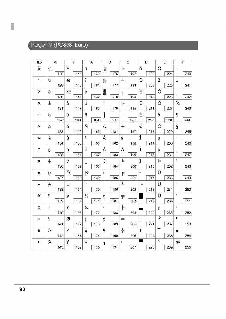
92
Page 19 (PC858: Euro)
HEX 8 9 A B C D E F
0
Ç 128
É 144
á 160
░ 176
└ 192
ð 208
Ó 224
- 240
1
ü 129
æ 145
í 161
▒ 177
┴ 193
Ð 209
β 225
± 241
2
é 130
Æ 146
ó 162
▓ 178
┬ 194
Ê 210
Ô 226
242
3
â 131
ô 147
ú 163
│ 179
├ 195
Ë 211
Ò 227
¾ 243
4
ä 132
ö 148
ñ 164
┤ 180
─ 196
È 212
õ 228
¶ 244
5
à 133
ò 149
Ñ 165
Á 181
┼ 197
€ 213
Õ 229
§ 245
6
å 134
û 150
a 166
 182
ã 198
Í 214
μ 230
÷ 246
7
ç 135
ù 151
o 167
À 183
à 199
Î 215
þ 231
¸ 247
8
ê 136
ÿ 152
¿ 168
© 184
╚ 200
Ï 216
Þ 232
° 248
9
ë 137
Ö 153
® 169
╣ 185
╔ 201
┘ 217
Ú 233
¨ 249
A
è 138
Ü 154
¬ 170
║ 186
╩ 202
┌ 218
Û 234
· 250
B
ï 139
ø 155
½ 171
╗ 187
╦ 203
█ 219
Ù 235
¹ 251
C
î 140
£ 156
¼ 172
╝ 188
╠ 204
▄ 220
ý 236
³ 252
D
ì 141
Ø 157
¡ 173
¢ 189
═ 205
¦ 221
Ý 237
² 253
E
Ä 142
× 158
« 174
¥ 190
╬ 206
Ì 222
¯ 238
■ 254
F
Å 143
ƒ 159
» 175
┐ 191
¤ 207
▀ 223
´ 239
SP 255
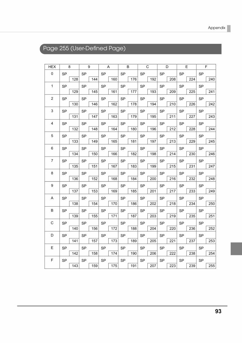
Appendix
93
Page 255 (User-Defined Page)
HEX 8 9 A B C D E F
0
SP 128
SP 144
SP 160
SP 176
SP 192
SP 208
SP 224
SP 240
1
SP 129
SP 145
SP 161
SP 177
SP 193
SP 209
SP 225
SP 241
2
SP 130
SP 146
SP 162
SP 178
SP 194
SP 210
SP 226
SP 242
3
SP 131
SP 147
SP 163
SP 179
SP 195
SP 211
SP 227
SP 243
4
SP 132
SP 148
SP 164
SP 180
SP 196
SP 212
SP 228
SP 244
5
SP 133
SP 149
SP 165
SP 181
SP 197
SP 213
SP 229
SP 245
6
SP 134
SP 150
SP 166
SP 182
SP 198
SP 214
SP 230
SP 246
7
SP 135
SP 151
SP 167
SP 183
SP 199
SP 215
SP 231
SP 247
8
SP 136
SP 152
SP 168
SP 184
SP 200
SP 216
SP 232
SP 248
9
SP 137
SP 153
SP 169
SP 185
SP 201
SP 217
SP 233
SP 249
A
SP 138
SP 154
SP 170
SP 186
SP 202
SP 218
SP 234
SP 250
B
SP 139
SP 155
SP 171
SP 187
SP 203
SP 219
SP 235
SP 251
C
SP 140
SP 156
SP 172
SP 188
SP 204
SP 220
SP 236
SP 252
D
SP 141
SP 157
SP 173
SP 189
SP 205
SP 221
SP 237
SP 253
E
SP 142
SP 158
SP 174
SP 190
SP 206
SP 222
SP 238
SP 254
F
SP 143
SP 159
SP 175
SP 191
SP 207
SP 223
SP 239
SP 255

94
International Character Sets
23 24 40 5B 5C 5D 5E 60 7B 7C 7D 7E
# $ @ [ ] ^ ` { | } ~
# $ à ° ç § ^ ` é ù è ¨
# $ § Ä Ö Ü ^ ` ä ö ü β
£ $ @ [ ] ^ ` { | } ~
# $ @ Æ Ø Å ^ ` æ ø å ~
# ¤ É Ä Ö Å Ü é ä ö å ü
# $ @ ° é ^ ù à ò è ì
Pt $ @ ¡ Ñ ¿ ^ ` ¨ ñ } ~
# $ @ [ ¥ ] ^ ` { | } ~
# ¤ É Æ Ø Å Ü é æ ø å ü
# $ É Æ Ø Å Ü é æ ø å ü
# $ á ¡ Ñ ¿ é ` í ñ ó ú
# $ á ¡ Ñ ¿ é ü í ñ ó ú
# $ @ [ W ] ^ ` { | } ~
# $ Ž Š Đ Ć Č ž š đ ć č
# Ұ @ [ ] ^ ` { | } ~
ASCII code (Hex)Country
USAFranceGermanyU.K.Denmark ISwedenItalySpain IJapanNorwayDenmark IISpain IILatin AmericaKoreaSlovenia/CroatiaChina
\
\
\
\