Embed Size (px)
Citation preview

Technical Presentation – Amy Dendulk

Main Projects:
•14 Fr Unable to Pass
• 23 Fr 2 Year Aging
• 23 Fr New Valve Design
14 Fr Introducer – Unable to Pass Overview of Issue 3
- Design Requires 14Fr Tip to expand to accommodate CP
- 16 SPRs due to unable to pass tip Dec-Apr
Unable to pass tip
Flow Back Length (mm)
Unable to Pass SPRs

Insertion/Removal Force4
Purpose• Evaluate insertion/removal forces of Impella CP through distal tip of
sheath
Verification Test• No changes to current setup
• Water at 37°C • Impella device (Large OD)
Additional Testing• Water replaced with porcine blood at 37°C • 3 insertions/removals – Multiple Insertions increases force• Evaluated w/ introducers at varying conditions (MDX, Silicone Oil, FB
Length)• Impella device
• Pin with formed cannula, to set dimensions• Impella device (Large OD)

Step Height Insertion Evaluation5
Inse
rtio
n F
orce
(N
)
Insertion Distance (mm)
Dilator Tip
Dilator Body
Sheath Tip
SheathBody
Dilator Tip Dilator body
Purpose• Use silicone media to compare sheath tip (step transition)
insertion forces of current and new tip profile.• No link to clinical application• Used for comparison to current design only
Test Description• Dilator and dilator/sheath combination inserted into silicone
substrate using Instron machine. • Measure force of silicone media to “overcome” tip step. • ID of silicone media varied
Force Profile Example
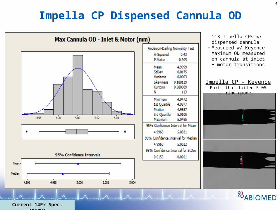
Impella CP Dispensed Cannula OD6
- 113 Impella CPs w/ dispensed cannula
- Measured w/ Keyence- Maximum OD measured on
cannula at inlet + motor transitions
Impella CP – KeyenceParts that failed 5.05 ring gauge
Current 14Fr Spec. [BACK]
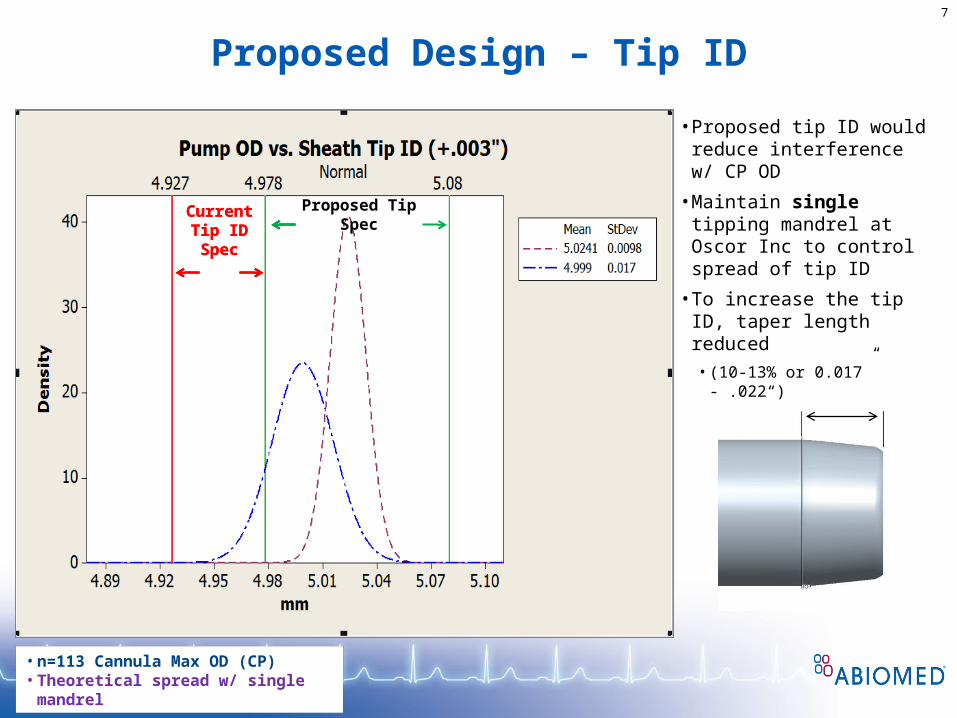
Proposed Design – Tip ID7
• n=113 Cannula Max OD (CP) • Theoretical spread w/ single mandrel
Current Tip ID Spec
Proposed Tip Spec
• Proposed tip ID would reduce interference w/ CP OD
• Maintain single tipping mandrel at Oscor Inc to control spread of tip ID
• To increase the tip ID, taper length reduced
• (10-13% or 0.017” - .022“)
Current Tip ID Spec
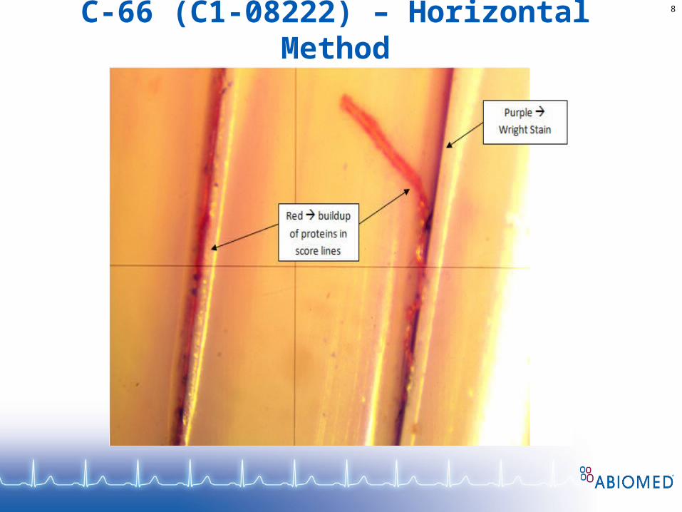
C-66 (C1-08222) – Horizontal Method8
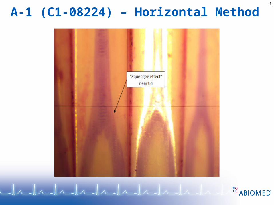
A-1 (C1-08224) – Horizontal Method9

23 Fr 2 Year Aging (29 Samples)
Testing done:
-Leak
-Insertion/Removal Forces
-Sheath Kink
-Sidearm Flush Force
Reports Written:
-Sheath Kink
-Sidearm Flush Force
11
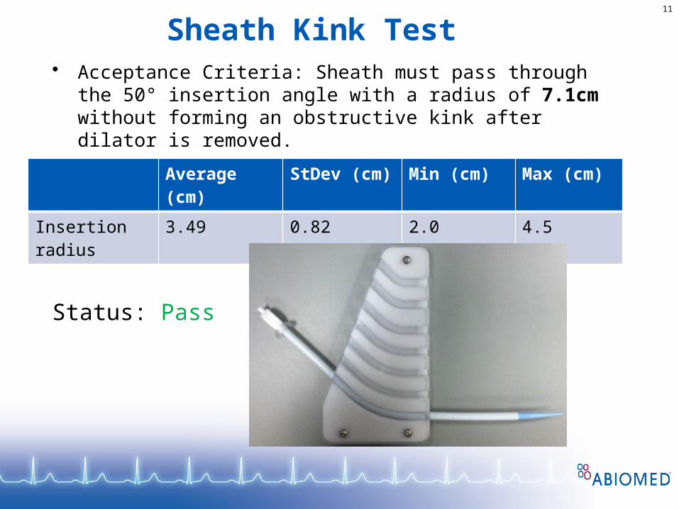
Sheath Kink Test• Acceptance Criteria: Sheath must pass through the 50°
insertion angle with a radius of 7.1cm without forming an obstructive kink after dilator is removed.
Status: Pass
Average (cm) StDev (cm) Min (cm) Max (cm)
Insertion radius 3.49 0.82 2.0 4.5

12
Hub Sidearm Flush Force Test• Acceptance Criteria: Maximum force required to flush 8 ml of
saline through sidearm must be no more than 12N.
Status: Pass
Average (N) StDev (N) Min (N) Max (N)
Flush Force 9.68 0.93 7.86 11.44

RP Pump Insertion/Removal Test13
Condition Average (N)
StDev (N) Min (N) Max (N)
Insert dilator 11.4 3.4 4.4 19.2
Remove dilator 12.3 2.0 7.0 17.0
Remove 6Fr diagnostic catheter
1.5 0.9 0.5 5.0
Insert pump through valve/hub
13.9 5.2 7.6 23.8
Insert pump through sheath
3.4 1.0 1.7 5.3
Remove guidewire
3.1 1.7 0.6 10.7
Remove pump 10.7 2.5 7.1 20.8
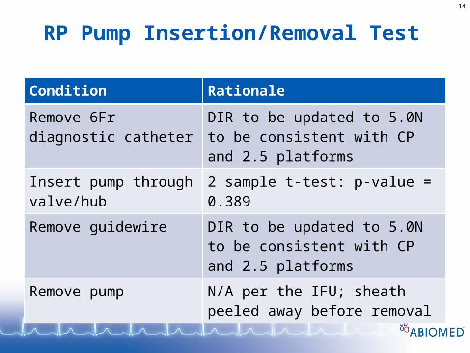
RP Pump Insertion/Removal Test
14
Condition Rationale
Remove 6Fr diagnostic catheter
DIR to be updated to 5.0N to be consistent with CP and 2.5 platforms
Insert pump through valve/hub
2 sample t-test: p-value = 0.389
Remove guidewire DIR to be updated to 5.0N to be consistent with CP and 2.5 platforms
Remove pump N/A per the IFU; sheath peeled away before removal
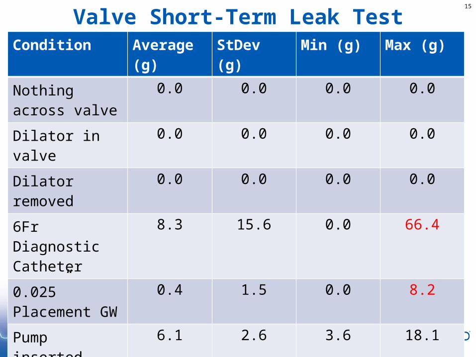
Valve Short-Term Leak Test15
Condition Average (g)
StDev (g) Min (g) Max (g)
Nothing across valve
0.0 0.0 0.0 0.0
Dilator in valve 0.0 0.0 0.0 0.0
Dilator removed 0.0 0.0 0.0 0.0
6Fr Diagnostic Catheter
8.3 15.6 0.0 66.4
0.025” Placement GW
0.4 1.5 0.0 8.2
Pump inserted 6.1 2.6 3.6 18.1
RP Pump & 0.025” GW
9.5 16.5 0.1 68.1
Pump Catheter 2.5 3.9 0.0 13.3
Total Leakage 26.8 34.7 4.3 145.3
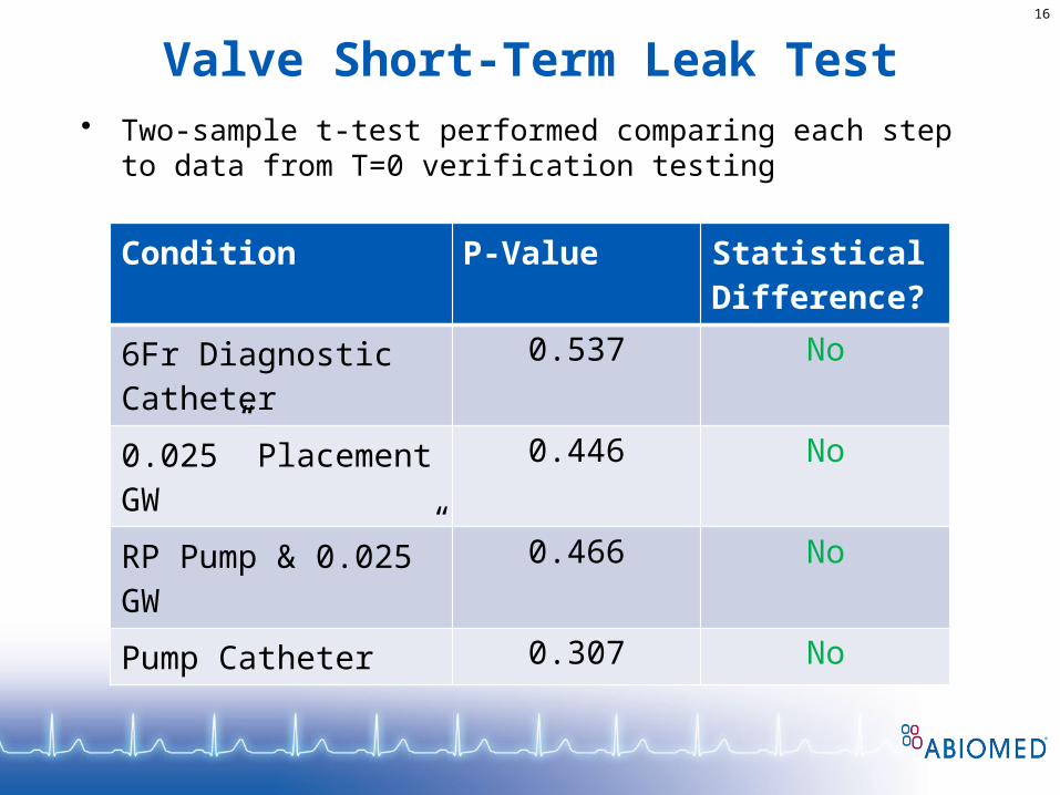
Valve Short-Term Leak Test16
Condition P-Value Statistical Difference?
6Fr Diagnostic Catheter
0.537 No
0.025” Placement GW 0.446 No
RP Pump & 0.025” GW
0.466 No
Pump Catheter 0.307 No
• Two-sample t-test performed comparing each step to data from T=0 verification testing

Axillary Implant Kit – New Valve Design
Valve Options18
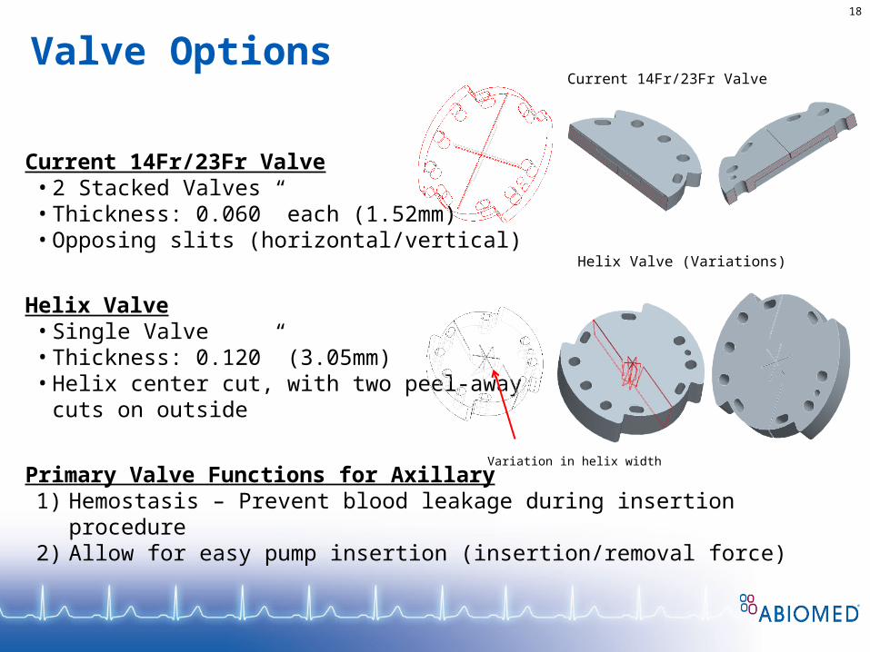
Current 14Fr/23Fr Valve• 2 Stacked Valves• Thickness: 0.060” each (1.52mm)• Opposing slits (horizontal/vertical)
Helix Valve• Single Valve• Thickness: 0.120” (3.05mm)• Helix center cut, with two peel-away
cuts on outside
Primary Valve Functions for Axillary1) Hemostasis – Prevent blood leakage during insertion procedure2) Allow for easy pump insertion (insertion/removal force)
Current 14Fr/23Fr Valve
Helix Valve (Variations)
Variation in helix width
Valve Leakage19
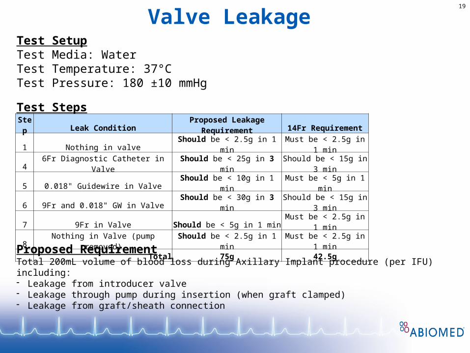
Test SetupTest Media: WaterTest Temperature: 37°CTest Pressure: 180 ±10 mmHg
Test Steps
Step Leak ConditionProposed Leakage
Requirement 14Fr Requirement
1 Nothing in valve Should be < 2.5g in 1 min Must be < 2.5g in 1 min
4 6Fr Diagnostic Catheter in Valve Should be < 25g in 3 minShould be < 15g in 3
min
5 0.018" Guidewire in Valve Should be < 10g in 1 min Must be < 5g in 1 min
6 9Fr and 0.018" GW in Valve Should be < 30g in 3 minShould be < 15g in 3
min
7 9Fr in Valve Should be < 5g in 1 min Must be < 2.5g in 1 min
8 Nothing in Valve (pump removed) Should be < 2.5g in 1 min Must be < 2.5g in 1 min
Total 75g 42.5g
Proposed RequirementTotal 200mL volume of blood loss during Axillary Implant procedure (per IFU) including:- Leakage from introducer valve- Leakage through pump during insertion (when graft clamped)- Leakage from graft/sheath connection
Valve Leakage (nominal)20
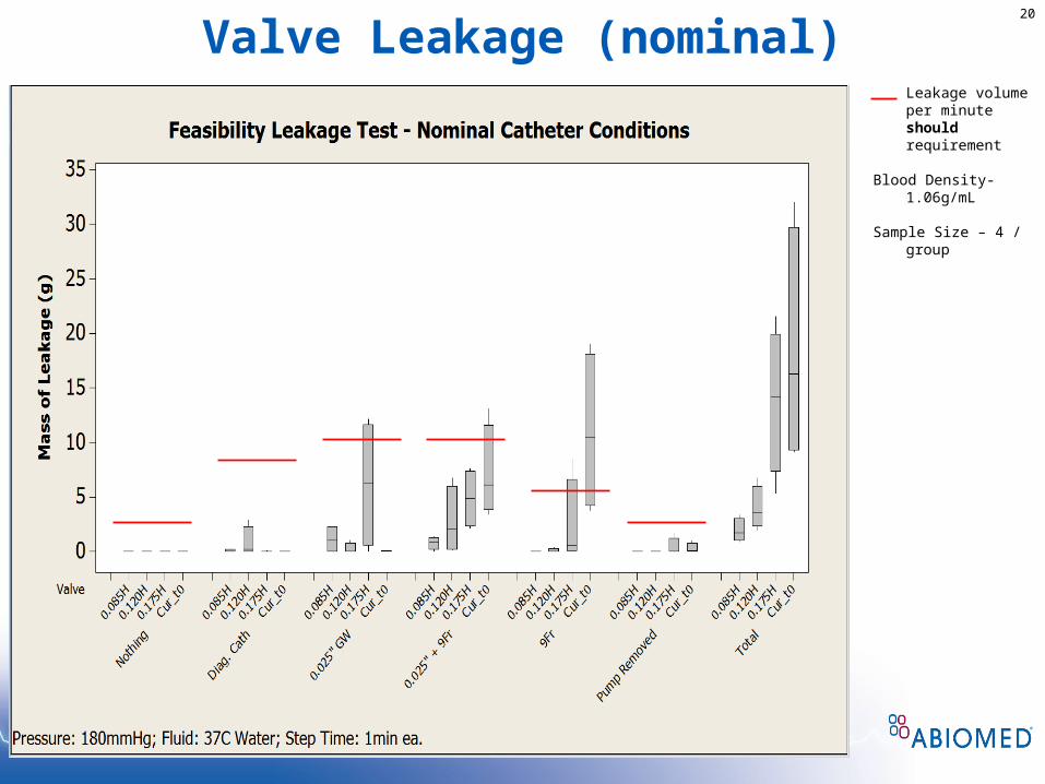
Leakage volume per minute should requirement
Blood Density- 1.06g/mL
Sample Size – 4 / group
Valve Leakage (extreme)21
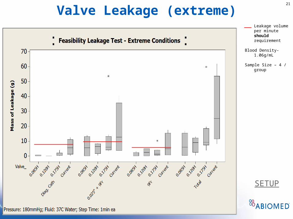
Leakage volume per minute should requirement
Blood Density- 1.06g/mL
Sample Size – 4 / group
SETUP
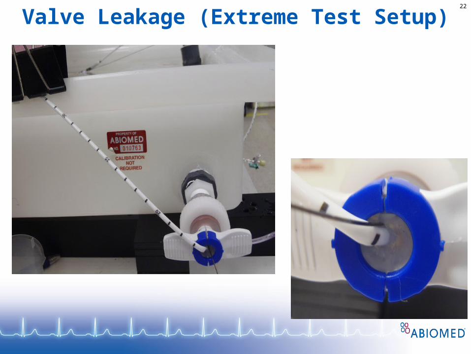
Valve Leakage (Extreme Test Setup)22

Insertion/Removal Testing23
Test SetupTest Media: WaterTest Temperature: 37°CSilicone Oil: MED400 1 drop (0.01mL)Speed: 120in/min
Insertion Test Steps
Step Pump Section
1 Pigtail (1.5”)
2 Inlet (1”)
3 Cannula (0.75”)
4 Cannula (0.75”)
5 Pump Housing (1”)
6 Motor Housing (1”)
7 Catheter (1”)
Proposed Requirement• Insertion force of the Impella 5.0 through hemostasis valve
must be less than 20N, should be less than 15N.• Insertion force of the Impella 5.0 through sheath and
graft must be less than 10N.
Pigtail Inlet Cannula Cannula Pump Housing
Motor Housing
Catheter
MED-400 Application to Helix
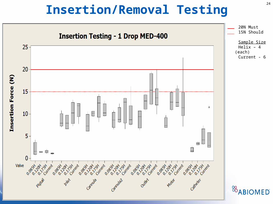
Insertion/Removal Testing24
20N Must15N Should
Sample SizeHelix – 4 (each)Current - 6

Insertion/Removal Testing25
20N Must15N Should
Sample SizeHelix – 4 (each)Current - 8

S.E.M. Work
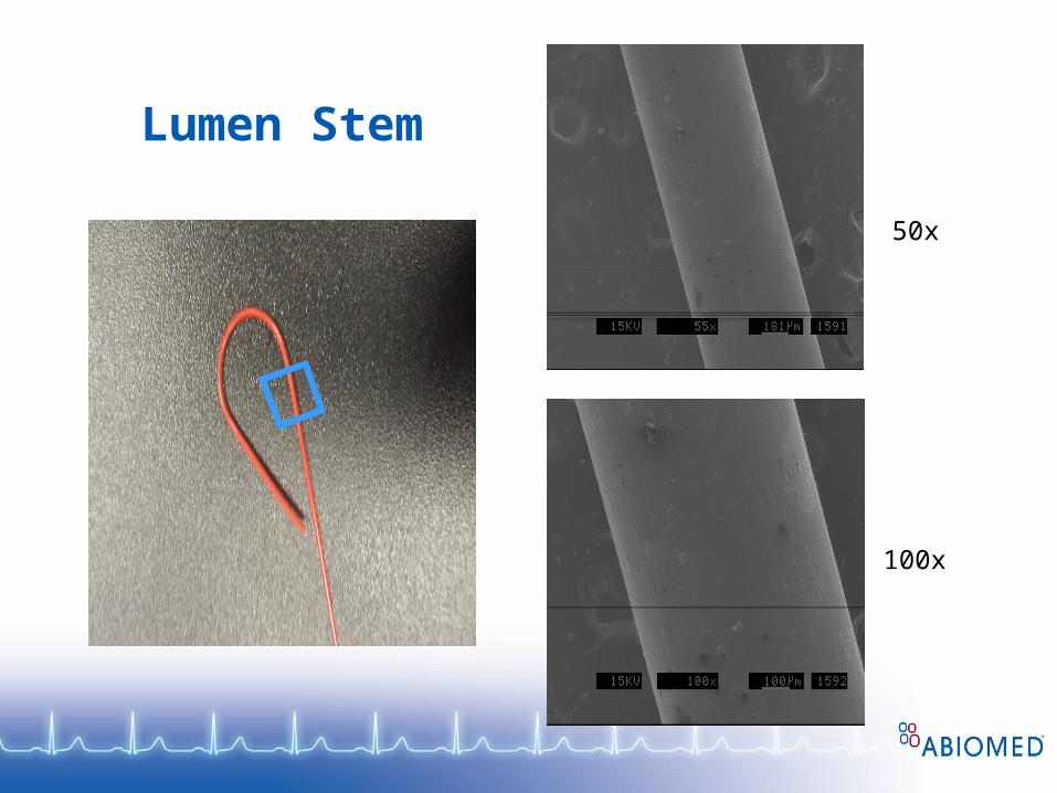
Lumen Stem
50x
100x

Pigtail Loop
50x
100x

The End!


![· Web viewVol. 44. September 25, 1979 [44 FR 55173] Revision. Vol. 45 . January 23, 1980 [45 FR 5617] Revision. Vol. 45. April 4, 1980 [45 FR 23379] Revision. Vol. 45. December](https://img.pdfslide.us/doc/110x75/5ac47c5c7f8b9ae06c8d41ca/viewvol-44-september-25-1979-44-fr-55173-revision-vol-45-january-23-1980.jpg)