Embed Size (px)
Citation preview
i
UNITED REPUBLIC OF TANZANIA
MINISTRY OF COMMUNICATIONS AND TRANSPORT
TECHNICAL REPORT
ON FEASIBILITY STUDY FOR IMPLEMENTATION OF
THE NATIONAL ICT BACKBONE INFRASTRACTURE
(United Republic of Tanzania)
Presented by:
Joint Team of Tanzania, CITCC and WorldTel
June, 2005
ii
Acknowledgement
The Government of the United Republic of Tanzania through the Ministry of
Communications and Transport (MoCT, in exercising her mandate formed a National
Steering Committee (see Appendix C) under the chairmanship of the Permanent Secretary
MoCT to assess the current national ICT Backbone status with the aim of implementing a
capacity rich, efficient and ubiquitous national broadband backbone infrastructure.
An assignment like this could not have been accomplished without help of others, whom we
would like to publicly acknowledge here. Firstly, The Steering Committee Members are
indebted to the Technical Working Group (see Appendix D) who did excellent work in facts
gathering, analysing and finally drafting this report. Similarly, the government on her side
owes appreciation and is grateful to all individuals (see Appendix E) who travelled all-over
the country for the purpose of verifying practicability of the National ICT backbone
infrastructure.
Secondly, the Steering Committee appreciates the time afforded by the Technical Working
Group and its Report Writing Group Members for their invaluable commitment, time and
constructive contributions in the course of conducting successful field survey for the OFC
backbone infrastructure and consequently preparing this report.
Thirdly, without reservations, the Steering Committee would also like to recognize valuable
contributions and commitments extended by TCRA, TRC, TANESCO, TTCL, TAZARA,
TPC, SONGAS and TISPA to the successful conductance of feasibility study and hence
preparation of this report. Particularly, the tireless efforts and valuable skills rendered by their
experts in making this exercise a success.
Finally and most important, the Steering Committee expresses sincere thanks and special
recognition to the Government of Tanzania through Ministry of Communications and
Transport (MOCT), Chinese Government, CITCC and WorldTel for their immeasurable
commitment and facilitation of successful performance of this undertaking.
iii
Table of Contents ACKNOWLEDGEMENT ...................................................................................................................................... II
EXECUTIVE SUMMARY......................................................................................................................................V
LIST OF ABBREVIATIONS AND ACRONYMS..........................................................................................VIII
LIST OF TABLES.................................................................................................................................................. IX
LIST OF FIGURES..................................................................................................................................................X
1. INTRODUCTION ........................................................................................................................................ 11
1.1 SCOPE OF THE REPORT........................................................................................................................... 11
1.2 COUNTRY PROFILE ................................................................................................................................ 11
1.2.1 General Information......................................................................................................................... 11
1.2.2 The State of Telecommunications .................................................................................................... 12
1.3 THE IMPORTANCE OF THE BACKBONE OFC PROJECT ........................................................................... 14
1.4 COMPOSITION OF THE WORKING TEAMS............................................................................................... 18
1.4.1 The Steering Committee ................................................................................................................... 18
1.4.2 The Technical Working Group and its Terms of Reference............................................................ 18
1.4.3 The Report Writing Group ............................................................................................................... 18
2 BACKGROUND INFORMATION............................................................................................................ 19
2.1 DEMAND FORECAST .............................................................................................................................. 19
2.2 EXISTING NETWORKS AND PLANS FOR OFC INFRASTRUCTURE ........................................................... 22
2.3 PROJECT SCOPE...................................................................................................................................... 23
3 THE PROPOSED OFC BACKBONE INFRASTRUCTURE PROJECT ............................................ 25
3.1 DESIGN CONSIDERATIONS ..................................................................................................................... 25
3.2 TRANSMISSION SYSTEMS....................................................................................................................... 25
3.2.1 Network Architecture of Transmission Systems .............................................................................. 26
3.2.2 Configuration of Transmission Line Capacity ................................................................................ 29
3.2.3 Protection Method............................................................................................................................ 30
iv
3.2.4 Network Management System.......................................................................................................... 31
3.2.5 Service Communication System ....................................................................................................... 31
3.2.6 Synchronisation System.................................................................................................................... 31
3.2.7 Equipment Selection......................................................................................................................... 31
3.2.8 Allocation of Transmission Equipment............................................................................................ 32
3.3 OFC LINE PLANT................................................................................................................................... 39
3.3.1 OFC Route Selection Criteria.......................................................................................................... 39
3.3.2 OFC Capacity .................................................................................................................................. 39
3.3.3 Scope of OFC Proposed Backbone OFC ........................................................................................ 40
3.3.4 OFC Laying and Installations ......................................................................................................... 46
3.4 ASSOCIATED CONSTRUCTION WORKS REQUIREMENT.......................................................................... 51
3.4.1 Requirement of Telecom Station ...................................................................................................... 51
3.4.2 Requirement for Power Supply System............................................................................................ 52
3.4.3 Power Supply Supervision System ................................................................................................... 57
3.4.4 Construction of OFC Duct System................................................................................................... 57
3.5 ESTIMATION OF INVESTMENT COST ...................................................................................................... 58
3.5.1 Explanation of BOQ......................................................................................................................... 58
3.5.2 BOQ and Price Schedules................................................................................................................ 58
3.6 PROPOSED IMPLEMENTATION SCHEDULE.............................................................................................. 59
E) CONCLUSION AND RECOMMENDATIONS....................................................................................... 62
4. APPENDICES............................................................................................................................................... 63
APPENDIX A: NETWORK DRAWINGS:.......................................................................................................... 63
APPENDIX B: SCHEDULES OF BILL OF QUANTITIES .................................................................................... 69
APPENDIX C: MEMBERS OF THE STEERING COMMITTEE............................................................................. 79
APPENDIX D: MEMBERS OF THE TECHNICAL WORKING GROUP.................................................................. 79
APPENDIX E: MEMBERS OF SURVEY TEAMS................................................................................................ 80
APPENDIX F: MEMBERS OF THE REPORT DRAFTING GROUP....................................................................... 80
APPENDIX G: REPORT ON STATUS OF THE NATIONAL ICT BACKBONE INFRASTRUCTURE.......................... 81
v
EXECUTIVE SUMMARY Resulting from the Government and Private sector authorities’ endorsement of the National
“Ideal” ICT Backbone Network provided in the Report on Status of the National ICT
Backbone Infrastructure (see Appendix G), the Ministry of Communication and
Transportation (MOCT) through the National ICT Backbone Steering Committee in
collaboration with WorlTel of Geneva, Switzerland and CITCC of China formed a Technical
Working Group (TWG) to perform a feasibility study on implementation of the National ICT
Backbone Infrastructure.
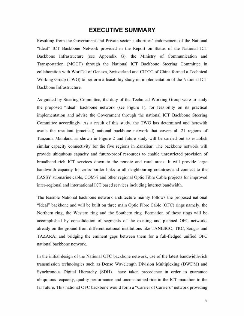
As guided by Steering Committee, the duty of the Technical Working Group were to study
the proposed “Ideal” backbone network (see Figure 1), for feasibility on its practical
implementation and advise the Government through the national ICT Backbone Steering
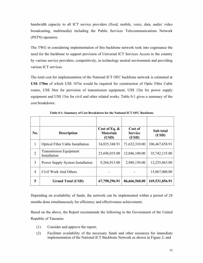
Committee accordingly. As a result of this study, the TWG has determined and herewith
avails the resultant (practical) national backbone network that covers all 21 regions of
Tanzania Mainland as shown in Figure 2 and future study will be carried out to establish
similar capacity connectivity for the five regions in Zanzibar. The backbone network will
provide ubiquitous capacity and future-proof resources to enable unrestricted provision of
broadband rich ICT services down to the remote and rural areas. It will provide large
bandwidth capacity for cross-border links to all neighbouring countries and connect to the
EASSY submarine cable, COM-7 and other regional Optic Fibre Cable projects for improved
inter-regional and international ICT based services including internet bandwidth.
The feasible National backbone network architecture mainly follows the proposed national
“Ideal” backbone and will be built on three main Optic Fibre Cable (OFC) rings namely, the
Northern ring, the Western ring and the Southern ring. Formation of these rings will be
accomplished by consolidation of segments of the existing and planned OFC networks
already on the ground from different national institutions like TANESCO, TRC, Songas and
TAZARA; and bridging the eminent gaps between them for a full-fledged unified OFC
national backbone network.
In the initial design of the National OFC backbone network, use of the latest bandwidth-rich
transmission technologies such as Dense Wavelength Division Multiplexing (DWDM) and
Synchronous Digital Hierarchy (SDH) have taken precedence in order to guarantee
ubiquitous capacity, quality performance and unconstrained ride in the ICT marathon to the
far future. This national OFC backbone would form a “Carrier of Carriers” network providing
vi
bandwidth capacity to all ICT service providers (fixed, mobile, voice, data, audio/ video
broadcasting, multimedia) including the Public Services Telecommunications Network
(PSTN) operators.
The TWG in considering implementation of this backbone network took into cognisance the
need for the backbone to support provision of Universal ICT Services Access to the country
by various service providers, competitively, in technology neutral environment and providing
various ICT services.
The total cost for implementation of the National ICT OFC backbone network is estimated at
US$ 170m of which US$ 107m would be required for construction of Optic Fibre Cable
routes, US$ 36m for provision of transmission equipment, US$ 12m for power supply
equipment and US$ 15m for civil and other related works. Table 0-1 gives a summary of the
cost breakdown.
Table 0-1: Summary of Cost Breakdown for the National ICT OFC Backbone
No. Description Cost of Eq. &
Materials (USD)
Cost of Service (USD)
Sub total (USD)
1 Optical Fiber Cable Installation 34,835,348.91 71,632,310.00 106,467,658.91
2 Transmission Equipment Installation 23,696,035.00 12,046,100.00 35,742,135.00
3 Power Supply System Installation 9,266,913.00 2,988,150.00 12,255,063.00
4 Civil Work And Others - - 15,067,000.00
5 Grand Total (USD) 67,798,296.91 86,666,560.00 169,531,856.91
Depending on availability of funds, the network can be implemented within a period of 24
months done simultaneously for efficiency and effectiveness achievement.
Based on the above, the Report recommends the following to the Government of the United
Republic of Tanzania:
(1) Consider and approve the report;
(2) Facilitate availability of the necessary funds and other resources for immediate implementation of the National ICT Backbone Network as shown in Figure 2; and
vii
(3) Facilitate sustainable institutional arrangements for management of the National OFC Backbone network.
Figure 1: The National “Ideal” ICT Broadband Backbone (Source Nov 2004 Report –Appendix G)
Figure 2: The National ICT OFC Backbone
viii
List of Abbreviations and Acronyms
BOQ - Bill of Quantities
CITCC - China International Telecommunications Construction Corporation
COMTEL - COMESA Telecommunications Company DDF - Digital Distribution Frame DWDM - Dense Wavelength Division Multiplexing EASSy - East African Sub-marine Cable System GDP - Gross Domestic Product HDPE - High-Density Polyethylene ICTs - Information and Communications Technologies IP - Internet Protocols ISPs - Internet Service Providers
MKUKUTA - Mkakati wa Kukuza Uchumi na Kuondoa Umaskini Tanzania
MOAT - Mobile Operators Association of Tanzania MoCT - Ministry of Communications and Transport OA - Optical Amplifier OADM - Optical add/drop Multiplexer ODF - Optical Distribution Frame OFC - Optic Fibre Cable OTM - Optical Terminal Multiplexer SDH - Synchronous Digital Hierarch SONGAS - Songosongo Gas Supply TANESCO - Tanzania Electric Supply Company TAZARA - Tanzania Zambia Railway Authority TCRA - Tanzania Communications Regulatory Authority TISPA - Tanzania Internet Service Providers Association TPC - Tanzania Posts Corporation TRC - Tanzania Railway Corporation TTCL - Tanzania Telecommunications Company Limited UNMDGs - United Nations Millennium Development Goals USD - United States Dollar WDM - Wavelength Division Multiplexing ZANTEL - Zanzibar Telecommunication Limited
ix
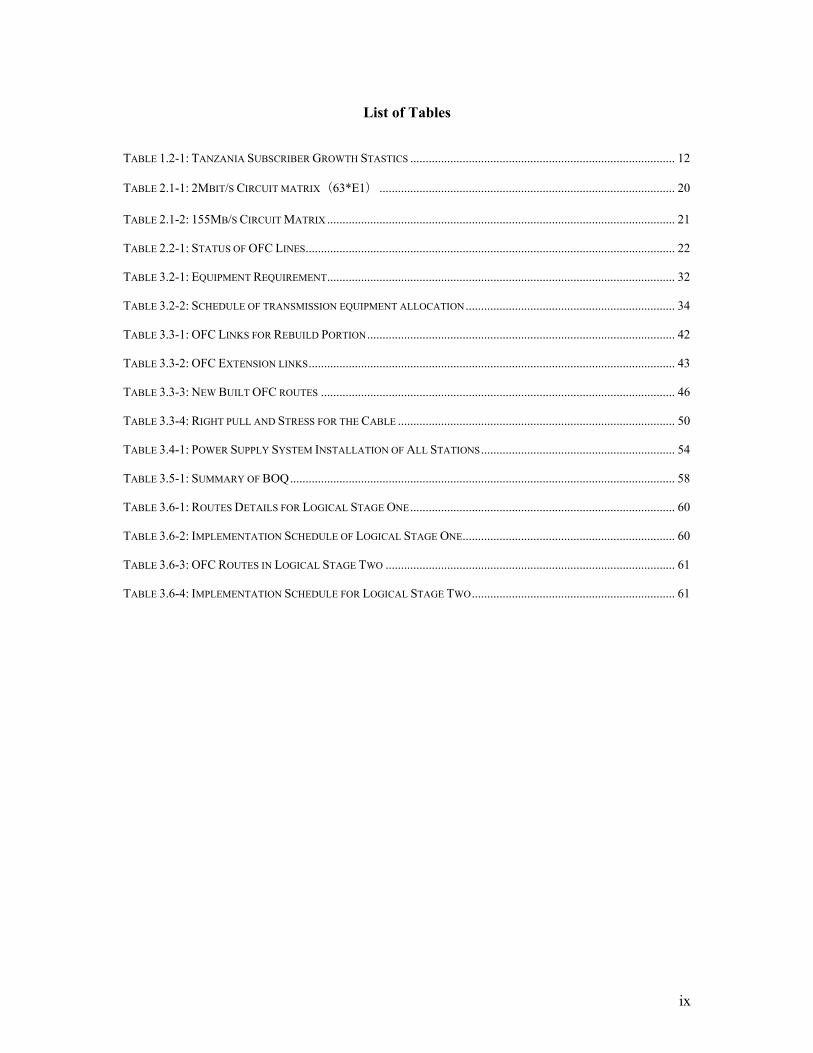
List of Tables
TABLE 1.2-1: TANZANIA SUBSCRIBER GROWTH STASTICS ...................................................................................... 12
TABLE 2.1-1: 2MBIT/S CIRCUIT MATRIX(63*E1) ................................................................................................ 20
TABLE 2.1-2: 155MB/S CIRCUIT MATRIX ................................................................................................................. 21
TABLE 2.2-1: STATUS OF OFC LINES........................................................................................................................ 22
TABLE 3.2-1: EQUIPMENT REQUIREMENT................................................................................................................. 32
TABLE 3.2-2: SCHEDULE OF TRANSMISSION EQUIPMENT ALLOCATION.................................................................... 34
TABLE 3.3-1: OFC LINKS FOR REBUILD PORTION.................................................................................................... 42
TABLE 3.3-2: OFC EXTENSION LINKS....................................................................................................................... 43
TABLE 3.3-3: NEW BUILT OFC ROUTES ................................................................................................................... 46
TABLE 3.3-4: RIGHT PULL AND STRESS FOR THE CABLE .......................................................................................... 50
TABLE 3.4-1: POWER SUPPLY SYSTEM INSTALLATION OF ALL STATIONS............................................................... 54
TABLE 3.5-1: SUMMARY OF BOQ............................................................................................................................. 58
TABLE 3.6-1: ROUTES DETAILS FOR LOGICAL STAGE ONE...................................................................................... 60
TABLE 3.6-2: IMPLEMENTATION SCHEDULE OF LOGICAL STAGE ONE..................................................................... 60
TABLE 3.6-3: OFC ROUTES IN LOGICAL STAGE TWO .............................................................................................. 61
TABLE 3.6-4: IMPLEMENTATION SCHEDULE FOR LOGICAL STAGE TWO.................................................................. 61
x
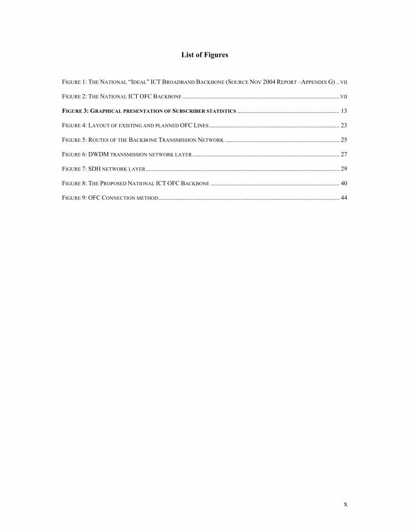
List of Figures
FIGURE 1: THE NATIONAL “IDEAL” ICT BROADBAND BACKBONE (SOURCE NOV 2004 REPORT –APPENDIX G) ..VII
FIGURE 2: THE NATIONAL ICT OFC BACKBONE .....................................................................................................VII
FIGURE 3: GRAPHICAL PRESENTATION OF SUBSCRIBER STATISTICS .................................................................. 13
FIGURE 4: LAYOUT OF EXISTING AND PLANNED OFC LINES .................................................................................... 23
FIGURE 5: ROUTES OF THE BACKBONE TRANSMISSION NETWORK .......................................................................... 25
FIGURE 6: DWDM TRANSMISSION NETWORK LAYER............................................................................................... 27
FIGURE 7: SDH NETWORK LAYER............................................................................................................................. 29
FIGURE 8: THE PROPOSED NATIONAL ICT OFC BACKBONE ................................................................................... 40
FIGURE 9: OFC CONNECTION METHOD..................................................................................................................... 44
11
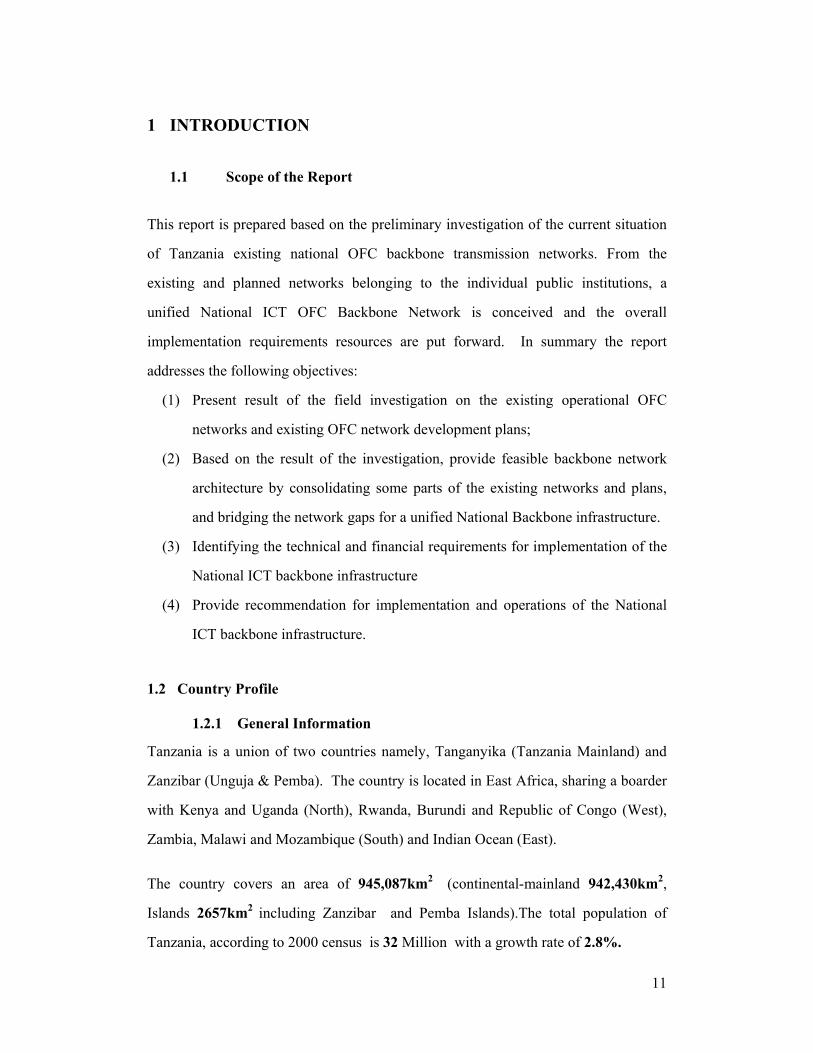
1 INTRODUCTION
1.1 Scope of the Report This report is prepared based on the preliminary investigation of the current situation
of Tanzania existing national OFC backbone transmission networks. From the
existing and planned networks belonging to the individual public institutions, a
unified National ICT OFC Backbone Network is conceived and the overall
implementation requirements resources are put forward. In summary the report
addresses the following objectives:
(1) Present result of the field investigation on the existing operational OFC
networks and existing OFC network development plans;
(2) Based on the result of the investigation, provide feasible backbone network
architecture by consolidating some parts of the existing networks and plans,
and bridging the network gaps for a unified National Backbone infrastructure.
(3) Identifying the technical and financial requirements for implementation of the
National ICT backbone infrastructure
(4) Provide recommendation for implementation and operations of the National
ICT backbone infrastructure.
1.2 Country Profile
1.2.1 General Information
Tanzania is a union of two countries namely, Tanganyika (Tanzania Mainland) and
Zanzibar (Unguja & Pemba). The country is located in East Africa, sharing a boarder
with Kenya and Uganda (North), Rwanda, Burundi and Republic of Congo (West),
Zambia, Malawi and Mozambique (South) and Indian Ocean (East).
The country covers an area of 945,087km2 (continental-mainland 942,430km2,
Islands 2657km2 including Zanzibar and Pemba Islands).The total population of
Tanzania, according to 2000 census is 32 Million with a growth rate of 2.8%.
12
Administratively, the United Republic of Tanzania has 25 Regions (Mainland 20 and
Islands 5) and 114 Districts. The 25 regions are Arusha, Coast, Dodoma, Iringa,
Kigoma, Mbeya, Mara, Kilimanjaro, Morogoro, Mtwara, Mwanza, Lindi, Ruvuma,
Shinyanga, Singida, Tabora, Tanga, Kagera, Rukwa, Dar es salaam, Zanzibar
Town/West, Zanzibar north, Zanzibar south, Pemba north, Pemba south.
The majority of Tanzanians (75%) dwell in rural areas while only 25% live in urban
areas. However, in recent years the rate of urbanization has been increasing
tremendously. The country is 45% forestry.
The country is blessed with natural resources like Diamond, Gold, Coal, Iron and
Natural Gas while staple food for the population include Corn, Wheat, Rice and Green
bananas. Coffee, Cotton, Sisal, Cashew and Clove serve as main economic crops in
the United Republic of Tanzania. The GDP (in 2002) stood at 8400 Billion Tanzanian
Shilling (about 865.9 Billion USD) at a growth rate of 6.2% (in 2002).
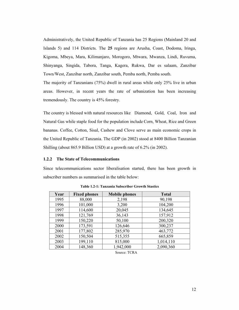
1.2.2 The State of Telecommunications
Since telecommunications sector liberalisation started, there has been growth in
subscriber numbers as summarised in the table below:
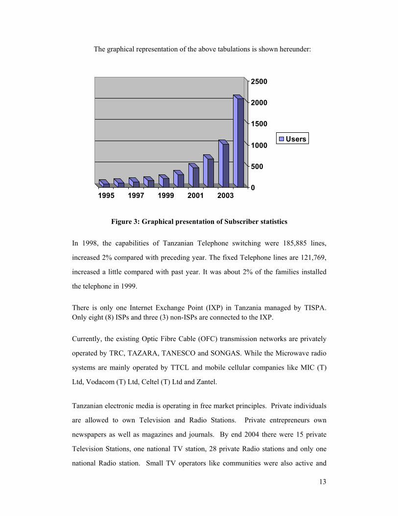
Table 1.2-1: Tanzania Subscriber Growth Stastics
Year Fixed phones Mobile phones Total 1995 88,000 2,198 90,198 1996 101,000 3,200 104,200 1997 114,600 20,045 134,645 1998 121,769 36,143 157,912 1999 150,220 50,100 200,320 2000 173,591 126,646 300,237 2001 177,802 285,970 463,772 2002 150,504 515,355 665,859 2003 199,110 815,000 1,014,110 2004 148,360 1,942,000 2,090,360
Source: TCRA
13
The graphical representation of the above tabulations is shown hereunder:
0
500
1000
1500
2000
2500
1995 1997 1999 2001 2003
Users
Figure 3: Graphical presentation of Subscriber statistics
In 1998, the capabilities of Tanzanian Telephone switching were 185,885 lines,
increased 2% compared with preceding year. The fixed Telephone lines are 121,769,
increased a little compared with past year. It was about 2% of the families installed
the telephone in 1999. There is only one Internet Exchange Point (IXP) in Tanzania managed by TISPA. Only eight (8) ISPs and three (3) non-ISPs are connected to the IXP. Currently, the existing Optic Fibre Cable (OFC) transmission networks are privately
operated by TRC, TAZARA, TANESCO and SONGAS. While the Microwave radio
systems are mainly operated by TTCL and mobile cellular companies like MIC (T)
Ltd, Vodacom (T) Ltd, Celtel (T) Ltd and Zantel.
Tanzanian electronic media is operating in free market principles. Private individuals
are allowed to own Television and Radio Stations. Private entrepreneurs own
newspapers as well as magazines and journals. By end 2004 there were 15 private
Television Stations, one national TV station, 28 private Radio stations and only one
national Radio station. Small TV operators like communities were also active and
14
there were 20 of them. On the other hand 15 cable TV operators were operational.
There are a number of private newspapers and magazines. On this regard therefore
adequate transmission capacities are very much needed.
1.3 The Importance of the Backbone OFC Project
Tanzania has a vision with relation to the development of ICT, that’s “Tanzania to
have a universally accessible broadband infrastructure and ICT solutions that enhance
sustainable socio-economic development and accelerated poverty reduction
nationally; become a hub of ICT Infrastructure regionally and be a full participant in
the global Information Society.” It is a well known phenomenon that
telecommunication plays a vital role in facilitating the social-economic development
thus well positioned to contribute significantly to the achievement of the objectives of
the National strategy for Economic Growth and Poverty Reduction in Tanzania
(MKUKUTA), National Development Vision 2005, and objectives of the United
Nations Millennium Development Goals (UNMDGs) 2015 for poverty reduction.
(a) Facilitation of National Economic Development
Communication is an important component of social fertility; Information industry is
basic for sound and strong national economy. The higher demands from the
communication industry are asked to facilitate rapid acceleration in the development
of the national economy. ICT is the key part of communication and the basic of
industry development and realization of sound rural economy. For developing country
like Tanzania, ICT backbone infrastructure is at the cross-roads, the impaired
developments of national communication system has caused unbalanced
developments between urban and rural economies. Therefore, for the long term
benefits, the government intension is to pioneer investments flow for support the
economy developments of balanced economies of scale. With this avail, the
government intends to construct the nationwide OFC backbone transmission network,
15
to increase the long distance circuit capacity. In her endeavours to take the ICT
services further, the Government has listed all potential remote and rural areas to be
considered for ICT services provision. The national ICT backbone infrastructure aims
at achieving this endeavor for facilitation of rapid economic development.
(b) To Fulfil the Increasing Demands to Information Services
Communication network is the principal part of information infrastructure, the carrier
of information exchanging and transmission. A long with the tremendous increase of
the new services and the market competition intensification, Tanzania is facing a new
challenge and chance. The needs of varies social fields to the multi-layer and
diversification of information transmission also grow tremendously. For fulfilling the
increasing demands to information services, expending the market shares and
developing the fields of new services, the construction of a long distance transmission
network is imperative under the cornered situation.
(c) To Strengthen the Competitive Abilities of the Domestic Operators
The field of ICT in Tanzania has been in an effective competition marketing structure.
A long with the foreign telecommunication operators participating in, the competition
on the market of Tanzanian telecom operation must be very intensity. So that, as soon
as possible to construct and improve a national backbone transmission network, and
then to provide the reliable circuits, optical fibers or communication ductworks for
hire to domestic telecom operators, to fulfill their needs on various new services and
the potential needs of network operation enterprises are strictly needed for strengthen
the Tanzania national competitive abilities. Strategically, the construction of Tanzania
National Backbone Network shall make Tanzania as one of the transmission centers
in its region. Realizing resources sharing of the National Backbone Infrastructure and
promoting the concept of a converged and interconnected network that would allow
stakeholders to ‘invest’ their networks to a grid of interconnectivity are very
important. Thus, the returns of their investments are sought from a broader
16
perspective than that of a point to point connection.
(d) Necessary to Develop the High Speed Broadband Transmission
The developments of telecommunication technologies are changing quickly. The
terms for updating the frameworks of telecom products are shorter and shorter again.
The data flux on the telecom network must exceed the voice one. It pushes the
traditional fixed telephone networks turn its development direction to the data
services, especially to that of centralized on IP services. Finally, the ICT must support
the new generation of Telecom Network that converged all of the confluent services
including voice over IP. Therefore, towards the new services, leading ahead properly,
to construct and improve the Tanzania national OFC Backbone as soon as possible,
adopting the advanced and successful network organization technologies and in lower
cost, Tanzania could rapidly and smoothly transit to an exceeding capacity, flexible
and high efficient, safe and reliable, economical and applicable and wide bandwidth
and high speed information network.
(e) To efficiently exploit the benefits from the EASSy Project
The EASSy project aims at providing high quality capacity optic fibre international
connectivity from Tanzania, to within Africa and the rest of the world and reducing
out payments to satellite telecommunications facility providers. In broad perspectives,
the objectives of the project are:
i. To improve high capacity optic fibre connectivity within East Africa and
provide a gateway for the region to the rest of the world;
ii. To bring the power of high speed and bandwidth connectivity to African
countries and the rest of world;
iii. To reduce unit costs (capital & operational) for global connectivity leading to
increased profits, lower tariffs and charges for end users;

17
iv. To provide direct routes through own infrastructure, obviating the need for
transits through third parties hence, reduced out payments;
v. To meet growing demand for Broadband (high bandwidth) Connectivity by
users such as Internet Service Providers, Data service providers, Broadcasters
and voice Service Providers; and
vi. To facilitate the expansion of inter-Africa trade through provision of better
and affordable communications in the region.
Countries in the Northern, Western and the Southern part of Africa currently are
connected by various undersea optical fibre cable systems which not only provide
intra-regional access for the countries connected to these systems, but also access to
other international submarine optical fibre cable systems to the rest of continents.
The East African seaboard and landlocked countries do not have such systems in
operation, nor plans to implement them in the near future. The only way for these
countries to gain access internationally is via satellites.
A broadband service via satellites in comparison with similar access via optical fibre
cables is very expensive. Satellite technology has technical constraints in terms of
limited available bandwidth / capacity, transient transmission delays, quality and
related prohibitive high bandwidth cost.
The EASSy project intends to implement a 9,900 Km under sea optical fibre cable
system that will link the whole of the Eastern Africa Seaboard starting at Mtunzini
near Durban in South Africa, the proposed submarine fibre cable will continue on
Northwards, branching out to Maputo in Mozambique, Mahajanga in Madagascar,
Dar Es Salaam and Zanzibar in Tanzania, Mombassa in Kenya and terminating at
Djibouti and at Port Sudan. Provision is also made for the cable to provide branching
to Mogadishu in Somalia.
18
Eastern Africa hinterlands and land-locked countries will be able to access the
proposed EASSy System at the cable’s appropriate shore landing stations at Mtunzini,
Maputo, Mahajanga, Dar Es Salaam, Mombassa, Mogadishu, Djibouti and Port
Sudan.
The current signatories of the EASSy project MoU in Tanzania are TTCL, ZANTEL
Ltd, and SATCOM AFRICA NETWORKS (T) Ltd.
1.4 Composition of the Working Teams
1.4.1 The Steering Committee
The Steering Committee under the chairmanship of the Permanent Secretary, MoCT
is made up of the Ministry of Communications and Transport, TCRA, Community
representatives and ICT stakeholders in the country.
1.4.2 The Technical Working Group and its Terms of Reference
Out of the Steering Committee members (Appendix C), a Technical Working Group
comprising of local Engineers and the CITCC (China) experts (Appendix D), was
formed. This Working Group was given the following Terms of References:-
(i) To study the proposed Ideal backbone as presented in the November,
2004 Report and based on it, conduct field survey and advice the
Government on practical realization of the Ideal National ICT
Backbone Infrastructure;
(ii) To establish the required estimated costs to construct the national
backbone;
(iii) To jointly work and present a report by 9th June 2005
1.4.3 The Report Writing Group
The Report Writing Group Members (Appendix: E) comprises both Tanzanians and
Chinese and was charged with putting in order the collected data and drafting of the
final Report.
19
2 BACKGROUNG INFORMATION
2.1 Demand Forecast
According to the Tanzanian vision on the National ICT OFC Infrastructure Backbone,
the main objective of this project is to form a telecom backbone transmission network
to satisfy domestic and global ICT requirements in the long term. It intends to provide
long-distance telephone networks, data backbone networks and extend Internet
bandwidth countrywide by offering sufficient capacities, network resiliency and
guaranteed quality of service provision to meet the needs of voice, data, mobile,
internet, leased circuit and more.
For the purpose of this investigation, the forecasted service demands are considered
within a period of 3 to 5 years. The following factors have been considered in
formulation of the service demand forecast: transmission requirements of different
operators including fixed, mobile and data communications, the ever increasing
requirement for transmission of high speed data, the development trend in
telecommunications sector including the potential development of future ICT services
and applications.
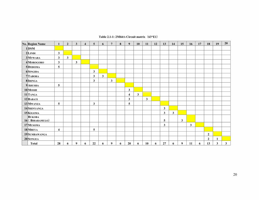
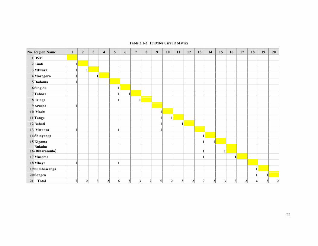
Detailed information on the forecasted 2Mb/s and 155Mb/s circuitries between
different areas is provided in Table 2.1-1 and Table 2.1-2 respectively. From the
tables it is evident that there is huge requirement of line capacity to transport ICT
services and applications between cities and thus need for putting in pace a high
capacity ICT backbone infrastructure.
20
Table 2.1-1: 2Mbit/s Circuit matrix(63*E1)
No. Region Name 1 2 3 4 5 6 7 8 9 10 11 12 13 14 15 16 17 18 19 20
1 DSM 2 LINDI 3 3 MTWARA 3 3 4 MOROGORO 3 3 5 DODOMA 5 6 SINGIDA 3 7 TABORA 3 3 8 IRINGA 3 3 9 ARUSHA 5
10 MOSHI 3 11 TANGA 4 3 12 BABATI 3 3 13 MWANZA 5 3 5 14 SHINYANGA 3 15 KIGOMA 3 3
16 BUKOBA ( BIHARAMULO) 5 3
17 MUSOMA 3 3 18 MBEYA 4 5 19 SUMBAWANGA 2 20 SONGEA 2 1
Total 28 6 9 6 22 6 9 6 20 6 10 6 27 6 9 11 6 13 3 3
21
Table 2.1-2: 155Mb/s Circuit Matrix
No. Region Name 1 2 3 4 5 6 7 8 9 10 11 12 13 14 15 16 17 18 19 20 1 DSM 2 Lindi 1 3 Mtwara 1 1 4 Morogoro 1 1 5 Dodoma 1 6 Singida 1 7 Tabora 1 1 8 Iringa 1 1 9 Arusha 1
10 Moshi 1 11 Tanga 1 1 12 Babati 1 1 13 Mwanza 1 1 1 14 Shinyanga 1 15 Kigoma 1 1
16 Bukoba (Biharamulo) 1 1
17 Musoma 1 1 18 Mbeya 1 1 19 Sumbawanga 1 20 Songea 1 1 21 Total 7 2 3 2 6 2 3 2 5 2 3 2 7 2 3 3 2 4 2 2
22
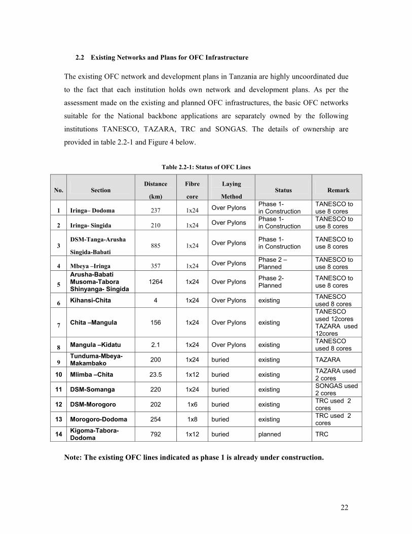
2.2 Existing Networks and Plans for OFC Infrastructure The existing OFC network and development plans in Tanzania are highly uncoordinated due
to the fact that each institution holds own network and development plans. As per the
assessment made on the existing and planned OFC infrastructures, the basic OFC networks
suitable for the National backbone applications are separately owned by the following
institutions TANESCO, TAZARA, TRC and SONGAS. The details of ownership are
provided in table 2.2-1 and Figure 4 below.
Table 2.2-1: Status of OFC Lines
No. Section Distance
(km)
Fibre
core
Laying
Method Status Remark
1 Iringa– Dodoma 237 1x24 Over Pylons Phase 1- in Construction
TANESCO to use 8 cores
2 Iringa- Singida 210 1x24 Over Pylons Phase 1- in Construction
TANESCO to use 8 cores
3 DSM-Tanga-Arusha
Singida-Babati 885 1x24 Over Pylons Phase 1-
in Construction TANESCO to use 8 cores
4 Mbeya –Iringa 357 1x24 Over Pylons Phase 2 – Planned
TANESCO to use 8 cores
5 Arusha-Babati Musoma-Tabora Shinyanga- Singida
1264 1x24 Over Pylons Phase 2- Planned
TANESCO to use 8 cores
6 Kihansi-Chita 4 1x24 Over Pylons existing TANESCO used 8 cores
7 Chita –Mangula 156 1x24 Over Pylons existing
TANESCO used 12cores TAZARA used 12cores
8 Mangula –Kidatu 2.1 1x24 Over Pylons existing TANESCO used 8 cores
9 Tunduma-Mbeya-Makambako 200 1x24 buried existing TAZARA
10 Mlimba –Chita 23.5 1x12 buried existing TAZARA used 2 cores
11 DSM-Somanga 220 1x24 buried existing SONGAS used 2 cores
12 DSM-Morogoro 202 1x6 buried existing TRC used 2 cores
13 Morogoro-Dodoma 254 1x8 buried existing TRC used 2 cores
14 Kigoma-Tabora-Dodoma 792 1x12 buried planned TRC
Note: The existing OFC lines indicated as phase 1 is already under construction.
23
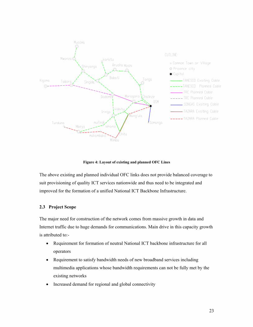
Figure 4: Layout of existing and planned OFC Lines
The above existing and planned individual OFC links does not provide balanced coverage to
suit provisioning of quality ICT services nationwide and thus need to be integrated and
improved for the formation of a unified National ICT Backbone Infrastructure.
2.3 Project Scope
The major need for construction of the network comes from massive growth in data and
Internet traffic due to huge demands for communications. Main drive in this capacity growth
is attributed to:-
• Requirement for formation of neutral National ICT backbone infrastructure for all
operators
• Requirement to satisfy bandwidth needs of new broadband services including
multimedia applications whose bandwidth requirements can not be fully met by the
existing networks
• Increased demand for regional and global connectivity

24
It is intended that after implementation of the project, the system would be able to provide
high capacity, network resiliency and quality performance for delivery of voice, data, IP
based and image services and applications, and will also provide fibre capacity for lease and
use by different operators. The system under this project is therefore geared to provide one
of the key vehicles for achievement of sound socio-economic and industrial developments.
In this project, a total of about 6997 km OFC lines will be constructed. The newly-built OFC
lines are 3,522 km, including 2,653 km of 48 cores and 869 km of 24 cores. For the rebuilt
OFC links a total of 3,475km will be constructed, including 3,430 km of 48 cores and 45 km
of 24 cores. About 160km of two HDPE pipe duct system would be constructed.
On the transmission equipments a total number of 93 DWDM and 39 SDH equipments and
their respective network management systems will be provided.
Apart from provision of the proposed OFC and transmission systems, the project will
provide power systems and equipment shelters.
25
3 THE PROPOSED OFC BACKBONE INFRASTRUCTURE PROJECT
3.1 Design Considerations
The following factors have been considered for design of the transmission backbone network
to be implemented:
(1) Provision of abundant capacity
(2) Guarantee high level of network resiliency and redundancy
(3) Guarantee high quality of performance of transmission systems
(4) Provide nationwide geographical coverage
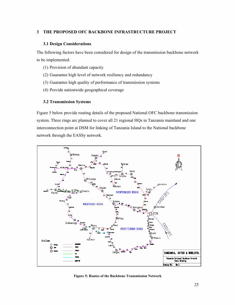
3.2 Transmission Systems Figure 5 below provide routing details of the proposed National OFC backbone transmission
system. Three rings are planned to cover all 21 regional HQs in Tanzania mainland and one
interconnection point at DSM for linking of Tanzania Island to the National backbone
network through the EASSy network.
Figure 5: Routes of the Backbone Transmission Network
26
3.2.1 Network Architecture of Transmission Systems
Considering factors such as market competition, use of existing network resources,
geographical location of different cities to be served,environment condition,development
trend and speed of different areas,status of national economy,population density and
service demands; the proposed architecture of the backbone transmission network is based
on two layers; the DWDM and SDH layers as described below:
a) Architecture of DWDM layer
The DWDM layer will provide upper transmission layer of the backbone network. The
DWDM will use ring framework. The rings will not only connect all regional centers and
major centers but will also provide abundant transmission capacity through the DWDM
equipment. By this way larger transmission capacities will be available throughout the
country to satisfy demands of different users using limited OFC resources. Three
transmission rings are proposed in the architecture namely: the Southern Ring, the Northern
and the Western Ring. Also the DWDM layer includes one (1) spur. The individual parts of
the DWDM layer are explained below as follows:
(i) The Northern ring
Route: DSM- The Dodoma – Singida- Shinyanga- Mwanza- Musoma- Babati
–Arusha- Moshi- Tanga- DSM,
Length: 2905km of OFC,
Stations: 28 stations including 14 OADM and 14 OA stations
(ii) The Southern ring
Route: DSM-Lindi- Mtwara- Songea- Mbeya—Iringa- Dodoma- Morogoro-
DSM,
Length: 2299km of OFC
Stations: 32 stations including 0 OADM and 22 OA stations
(iii) The Western ring
Route: Dodoma - Singida - Shinyanga - Mwanza - Biharamulo - Kigoma -
Tabora - Sumbawanga - Mbeya - Iringa – Dodoma.
Length: 3253km of OFC,
Stations: 31 stations including 14 OADM and 17 OA stations
27
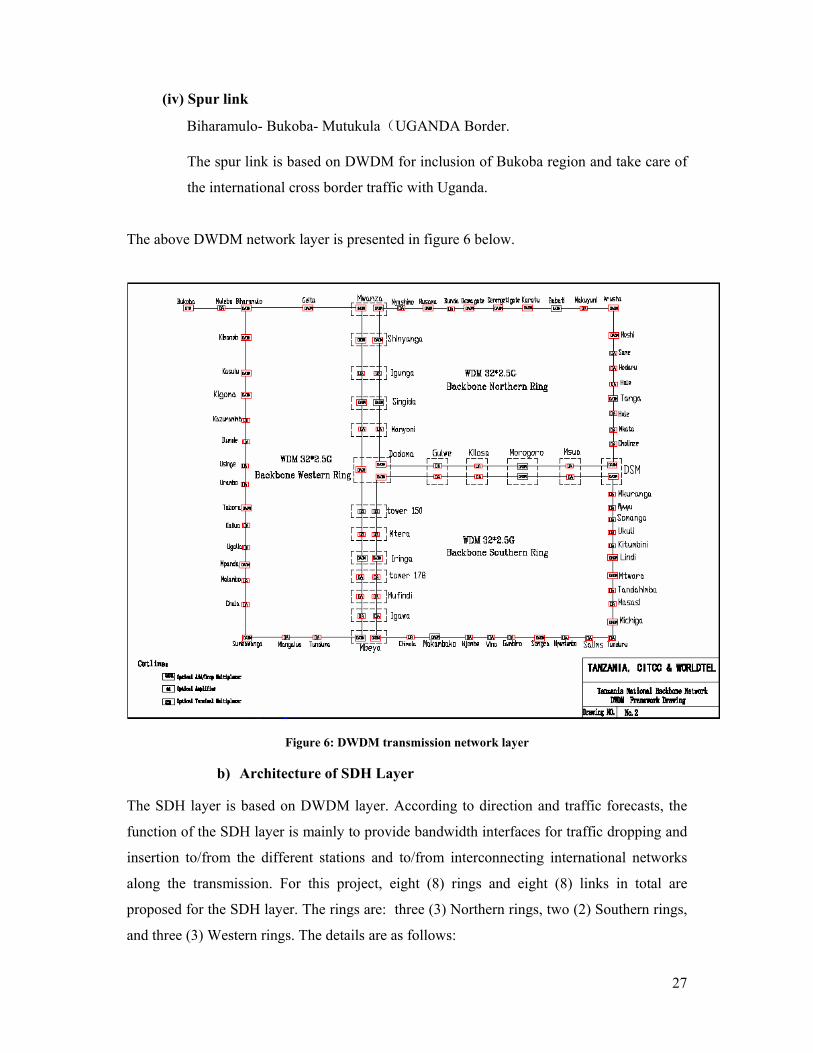
(iv) Spur link
Biharamulo- Bukoba- Mutukula(UGANDA Border.
The spur link is based on DWDM for inclusion of Bukoba region and take care of
the international cross border traffic with Uganda.
The above DWDM network layer is presented in figure 6 below.
Figure 6: DWDM transmission network layer
b) Architecture of SDH Layer
The SDH layer is based on DWDM layer. According to direction and traffic forecasts, the
function of the SDH layer is mainly to provide bandwidth interfaces for traffic dropping and
insertion to/from the different stations and to/from interconnecting international networks
along the transmission. For this project, eight (8) rings and eight (8) links in total are
proposed for the SDH layer. The rings are: three (3) Northern rings, two (2) Southern rings,
and three (3) Western rings. The details are as follows:
28
c) Northern Circuit
(i) Northern Ring No.1
DSM- Dodoma - Mwanza – Arusha. To take care of regional traffic routing between
Dodoma Mwanza and Arusha areas. There are four (4) stations in the SDH ring.
(ii) Northern Ring No.2
Arusha- Moshi - Tanga - Babati –Arusha. To take care of regional traffic routing
between Arusha Moshi Tanga and Babati regions. There are four (4) stations in the
ring.
(iii) Northern Ring No.3
Mwanza - Musoma - Shinyanga - Mwanza. To take care of regional traffic routing
between Mwanza Musoma and Shinyanga. There are three (3) stations in the ring.
d) Southern Circuit
(i) Southern Ring No.1
DSM - Dodoma - Mbeya - Songea –DSM. To take care of regional traffic routing
between DSM Dodoma and Mbeya.There are four (4) in the ring.
(ii) Southern Ring No.2
DSM-Lindi- Mtwara - Morogo-DSM. To take care of regional traffic routing
between DSM Lindi Mtwara and Morogo. There are four (4) stations in the ring.
e) Western Circuit
(i) Western Ring No.1
Mwanza - Biharamulo - Kingoma - Mwanza. To take care of regional traffic routing
between Mwanza, Bukoba and Kingoma. There are three (3) stations in the ring.
(ii) Western Ring No.2
Dodoma - Singida - Tabora - Dodoma. To take care of regional traffic routing
between Dodoma Singita and Tabora. There are three (3) stations in the ring.
(iii) Western Ring No.3 of SDH backbone transmission network
Dodoma - Sumbawanga - Mbeya - Iringa - Dodoma. To take care of regional traffic
routing between Dodoma Sumbawanga Mbeya and Iringa. There are four (4)
stations in the ring.
29
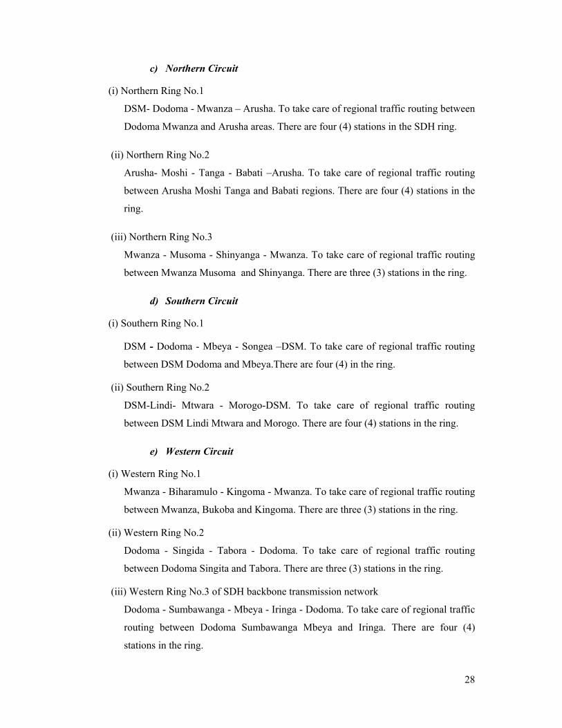
f) Spur links The SDH spur links are provided for international interconnect with bordering countries:
KENYA, ZAMBIA, MALAWI, UGANDA, RWANDA and BURUNDI. The total number
of station for the spur links is ten (10). The details of the SDH network is given in figure 7
below.
Figure 7: SDH network layer
3.2.2 Configuration of Transmission Line Capacity
All three OFC rings are provided with WDM-32 system based on SDH 2.5Gb/s line speed.
As per the traffic forecast, the Northern WDM ring is provided with 4x2.5Gb/s SDH
configuration, the Southern WDM ring with one 3x2.5Gb/s SDH configuration and the
Western WDM ring with one SDH 4x2.5Gb/s SDH configuration. The only Biharamulo –
Bukoba-Mtukula DWM link is provided with one (1+1)x2.5Gb/s SDH configuration.
30
3.2.3 Protection Method
a) WDM system protection
The WDM system can provide 1+1 optical layer line protection, 1+1 optical channel
protection and 1:N channel protection.
(i) 1+1 Optical line protection mode
The 1+1 Optical layer line protection involves protection at optical physical line level as
such two different physical OFC pairs are required to achieve protected line operation. Such
configuration is generally applied in chain networks.
(ii) 1+1 Optical channel protection mode
1+1 optical channel protection mode involves protection at card level can be used in ring
network but would still require use of two different optical cable pairs, one as working line,
and another as standby line. If one link fails, the system rearranges automatically itself to
secure uninterruptible communication services.
(iii) 1:N (N≤8)Wavelength protection mode
In the 1:N (N≤8)protection configuration, the standby wavelength channel is shared by all
N active channels. If either of the working wavelength channel fails, the protection channel
will take operation automatically according to the decision priority setup in place.
Under this project, 1:N (N<8) Wavelength Protection mode is employed.
b) SDH Network protection
Two kinds of protection modes are employed in the SDH layer: MSP in 1+1 / 1: N
protection and MS-SPRing protection (using two or four fibre core ring).
The MSP (1+1) protection method is employed in Optical SDH links and in this case,
TTCL’s SDH microwave links can provide protection if the SDH OFC network fails.
The MS-SPRing protection is employed in SDH rings and it uses two optical fibre cores.
c) Equipment board protection mode
For the main equipment board of DWDM and SDH, It adopts 1+1 protection, one board
working and another board standby. For branch board of SDH, it adopts 1: N protection.
31
3.2.4 Network Management System
According to the multi-layer structure of network management and operation system, two
layers of network management systems are employed for this backbone project: Sub-
network management (SNM) and Element management system (EMS) for separate
management of both WDM and SDH networks. The main SNM center will be in DSM and
will supervise the entire transmission network. The SNM center will manage two EMS
centers, one in DSM responsible for management of north and south ring; and another in
DODOMA responsible for management of West ring. The scope of supervision includes
fault management, control management, configuration management and security
management. For maintenance convenience reasons, local maintenance terminals are
provided for to each local maintenance centers for supervision of OADM station in the
WDM system. The local terminal can be used to configure new installations as well to
perform local maintenance operations.
3.2.5 Service Communication System
A communication system is require facilitate maintenance services in WDM system by
enabling voice communication among stations using E1 Octet of optical supervision circuit
(OSC). The system is provided with two calling methods: selective and conference telephone
calling.
3.2.6 Synchronisation System
Synchronisation system is used to provide synchronization signal to the transmission
network. It will be used to synchronize equipment in all stations using external timing
system (BITS) to be provided in this project. The ADM stations will achieve
synchronization by receiving satellite timing signal in initial stages. The timing signal will
bypass the SDH repeater stations (or SDH relay station). The external timing signal is 2Mb/s
(framed) or 2MHz (unframed).
3.2.7 Equipment Selection
a) Selection Criteria
The transmission Equipments in this project should be in accordance with ITU-T relevant
recommendations. DWDM system equipments will be selected and for interfacing with
SDH equipment wave length converter will be adopted. The optical interface should be in
32
accordance with ITU G. 957 standard. The SDH transmission equipment should be in
accordance with ITU G.813 standard. The protection between rings should be in compliance
to with ITU G.842 standard. The Working power supply to be employed is -48v positive
pole grounding. Equipment Cabinet height is 2.6, 2.2 or 2.0 meters.
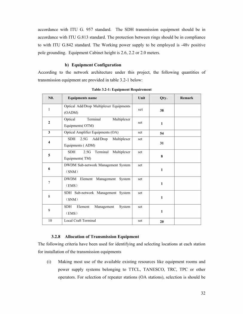
b) Equipment Configuration
According to the network architecture under this project, the following quantities of
transmission equipment are provided in table 3.2-1 below:
Table 3.2-1: Equipment Requirement
N0. Equipments name Unit Qty. Remark
1 Optical Add/Drop Multiplexer Equipments
(OADM) set 38
2 Optical Terminal Multiplexer
Equipments( OTM) set 1
3 Optical Amplifier Equipments (OA) set 54
4 SDH 2.5G Add/Drop Multiplexer
Equipments ( ADM)
set 31
5 SDH 2.5G Terminal Multiplexer
Equipments( TM)
set 8
6 DWDM Sub-network Management System
(SNM)
set 1
7 DWDM Element Management System
(EMS)
set 1
8 SDH Sub-network Management System
(SNM)
set 1
9 SDH Element Management System
(EMS)
set 1
10 Local Craft Terminal set 20
3.2.8 Allocation of Transmission Equipment
The following criteria have been used for identifying and selecting locations at each station
for installation of the transmission equipments
(i) Making most use of the available existing resources like equipment rooms and
power supply systems belonging to TTCL, TANESCO, TRC, TPC or other
operators. For selection of repeater stations (OA stations), selection is should be
33
left for the best among available equipment rooms. In case there have no existing
equipment room or the existing room does not have enough space, then the only
viable solution is to construct new equipment room or refurbish the existing one.
(ii) Availability of space (about 10-18 M2 for an OA and 35-70 M2 for Optical
Terminal Station) for construction of new sites.
(iii) Provision for extra space for future network expansions.
(iv) Requirement for interconnection to the existing PSTN operators centers.
(v) Suitability of stations in the design of the transmission nodes i.e distant between
stations is within the specified range.
According to different functions and applications, the transmission stations are categorized
as: ADM station, OTM station, OA station, TM station and Optical Jumper Station (OJ). The
total number of all stations is 150. Table 3.2-8 provide schedule of the equipment placement.
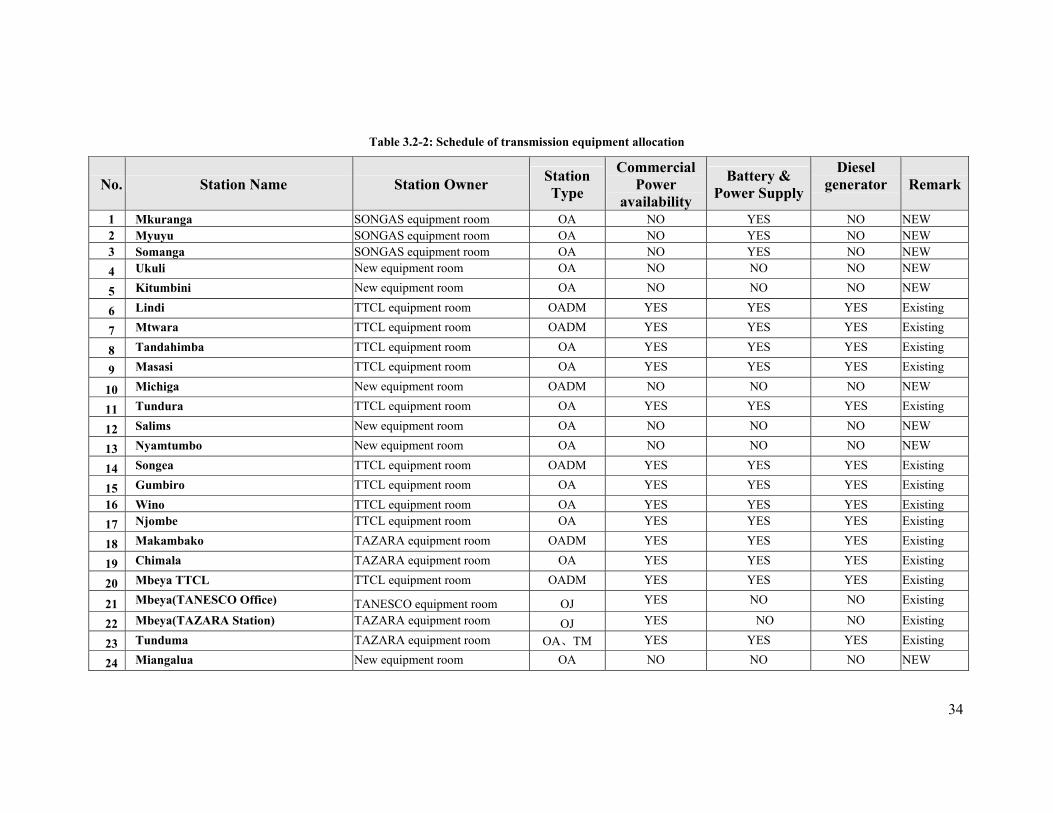
34
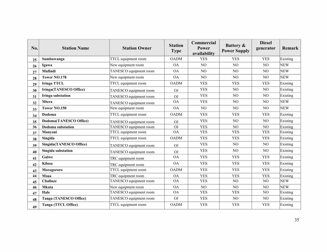
Table 3.2-2: Schedule of transmission equipment allocation
No. Station Name Station Owner Station Type
Commercial Power
availability
Battery & Power Supply
Diesel generator
Remark
1 Mkuranga SONGAS equipment room OA NO YES NO NEW 2 Myuyu SONGAS equipment room OA NO YES NO NEW 3 Somanga SONGAS equipment room OA NO YES NO NEW 4 Ukuli New equipment room OA NO NO NO NEW
5 Kitumbini New equipment room OA NO NO NO NEW
6 Lindi TTCL equipment room OADM YES YES YES Existing
7 Mtwara TTCL equipment room OADM YES YES YES Existing
8 Tandahimba TTCL equipment room OA YES YES YES Existing
9 Masasi TTCL equipment room OA YES YES YES Existing
10 Michiga New equipment room OADM NO NO NO NEW
11 Tundura TTCL equipment room OA YES YES YES Existing
12 Salims New equipment room OA NO NO NO NEW
13 Nyamtumbo New equipment room OA NO NO NO NEW
14 Songea TTCL equipment room OADM YES YES YES Existing
15 Gumbiro TTCL equipment room OA YES YES YES Existing 16 Wino TTCL equipment room OA YES YES YES Existing 17 Njombe TTCL equipment room OA YES YES YES Existing
18 Makambako TAZARA equipment room OADM YES YES YES Existing
19 Chimala TAZARA equipment room OA YES YES YES Existing
20 Mbeya TTCL TTCL equipment room OADM YES YES YES Existing
21 Mbeya(TANESCO Office) TANESCO equipment room OJ YES NO NO Existing
22 Mbeya(TAZARA Station) TAZARA equipment room OJ YES NO NO Existing
23 Tunduma TAZARA equipment room OA、TM YES YES YES Existing
24 Miangalua New equipment room OA NO NO NO NEW
35
No. Station Name Station Owner Station Type
Commercial Power
availability
Battery & Power Supply
Diesel generator
Remark
25 Sumbawanga TTCL equipment room OADM YES YES YES Existing
26 Igawa New equipment room OA NO NO NO NEW
27 Mufindi TANESCO equipment room OA NO NO NO NEW
28 Tower NO.178 New equipment room OA NO NO NO NEW
29 Iringa TTCL TTCL equipment room OADM YES YES YES Existing
30 Iringa(TANESCO Office) TANESCO equipment room OJ YES NO NO Existing
31 Iringa substation TANESCO equipment room OJ YES NO NO Existing
32 Mtera TANESCO equipment room OA YES NO NO NEW
33 Tower NO.150 New equipment room OA NO NO NO NEW
34 Dodoma TTCL equipment room OADM YES YES YES Existing
35 Dodoma(TANESCO Office) TANESCO equipment room OJ YES NO NO Existing 36 Dodoma substation TANESCO equipment room OJ YES NO NO Existing 37 Manyoni TTCL equipment room OA YES YES YES Existing
38 Singida TTCL equipment room OADM YES YES YES Existing
39 Singida(TANESCO Office) TANESCO equipment room OJ YES NO NO Existing
40 Singida substation TANESCO equipment room OJ YES NO NO Existing
41 Gulwe TRC equipment room OA YES YES YES Existing
42 Kilosa TRC equipment room OA YES YES YES Existing
43 Morogororo TTCL equipment room OADM YES YES YES Existing 44 Msua TRC equipment room OA YES YES YES Existing 45 Chalinze TANESCO equipment room OA YES NO NO NEW 46 Mkata New equipment room OA NO NO NO NEW 47 Hale TANESCO equipment room OA YES YES NO Existing
48 Tanga (TANESCO Office) TANESCO equipment room OJ YES NO NO Existing
49 Tanga (TTCL Office) TTCL equipment room OADM YES YES YES Existing
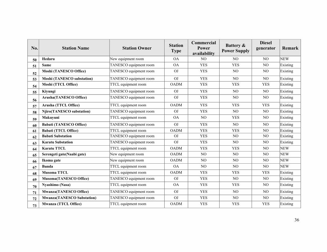
36
No. Station Name Station Owner Station Type
Commercial Power
availability
Battery & Power Supply
Diesel generator
Remark
50 Hedaru New equipment room OA NO NO NO NEW
51 Same TANESCO equipment room OA YES YES NO Existing
52 Moshi (TANESCO Office) TANESCO equipment room OJ YES NO NO Existing
53 Moshi (TANESCO substation) TANESCO equipment room OJ YES NO NO Existing
54 Moshi (TTCL Office) TTCL equipment room OADM YES YES YES Existing
55 Kiyungi TANESCO equipment room OJ YES NO NO Existing
56 Arusha(TANESCO Office) TANESCO equipment room OJ YES NO NO Existing
57 Arusha (TTCL Office) TTCL equipment room OADM YES YES YES Existing
58 Njiro(TANESCO substation) TANESCO equipment room OJ YES NO NO Existing
59 Makuyuni TTCL equipment room OA NO YES NO Existing
60 Babati (TANESCO Office) TANESCO equipment room OJ YES NO NO Existing
61 Babati (TTCL Office) TTCL equipment room OADM YES YES NO Existing
62 Babati Substation TANESCO equipment room OJ YES NO NO Existing
63 Karatu Substation TANESCO equipment room OJ YES NO NO Existing
64 Karatu TTCL TTCL equipment room OADM YES YES NO NEW
65 Serengeti gate(Naabi gate) New equipment room OADM NO NO NO NEW
66 Ikoma gate New equipment room OADM NO NO NO NEW
67 Bunda TTCL equipment room OA NO NO NO NEW
68 Musoma TTCL TTCL equipment room OADM YES YES YES Existing
69 Musoma(TANESCO Office) TANESCO equipment room OJ YES NO NO Existing
70 Nyashimo (Nasa) TTCL equipment room OA YES YES NO Existing
71 Mwanza(TANESCO Office) TANESCO equipment room OJ YES NO NO Existing
72 Mwanza(TANESCO Substation) TANESCO equipment room OJ YES NO NO Existing
73 Mwanza (TTCL Office) TTCL equipment room OADM YES YES YES Existing
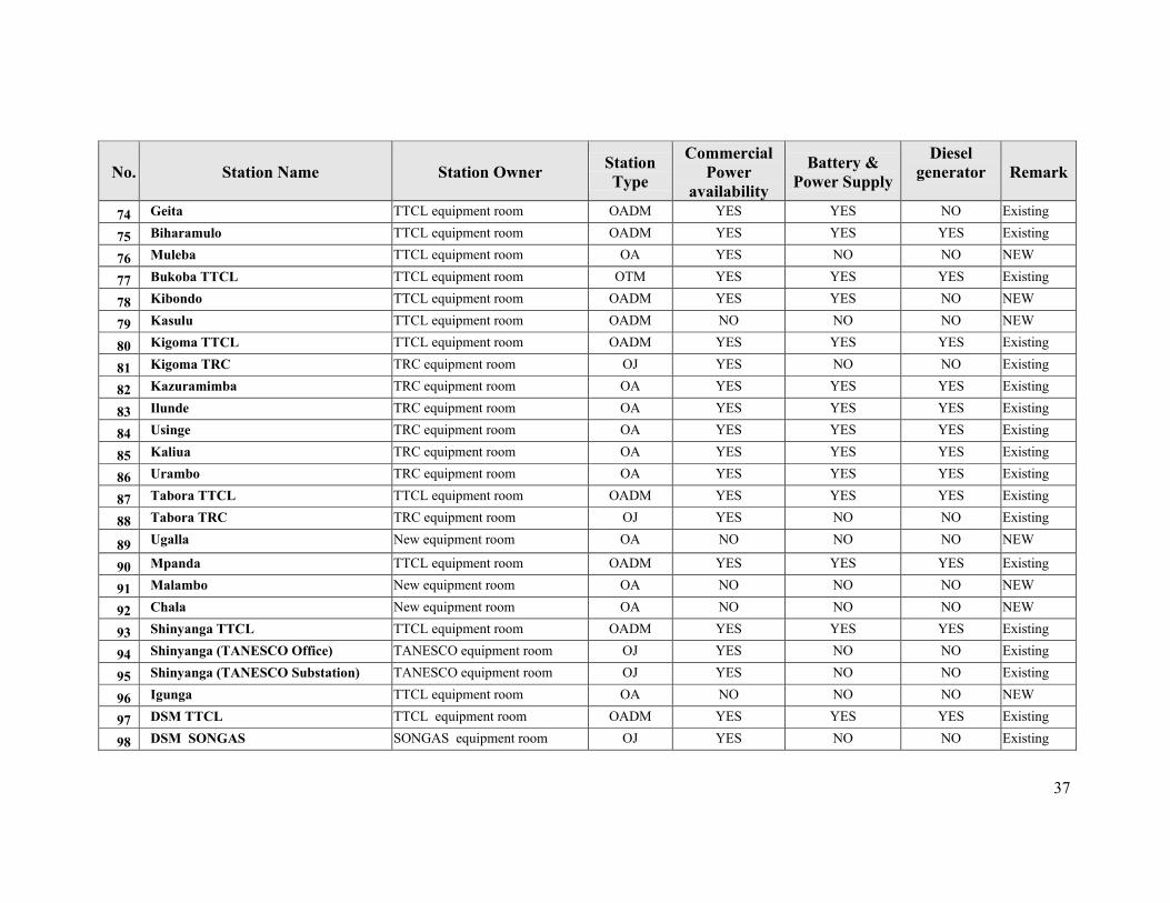
37
No. Station Name Station Owner Station Type
Commercial Power
availability
Battery & Power Supply
Diesel generator
Remark
74 Geita TTCL equipment room OADM YES YES NO Existing
75 Biharamulo TTCL equipment room OADM YES YES YES Existing
76 Muleba TTCL equipment room OA YES NO NO NEW
77 Bukoba TTCL TTCL equipment room OTM YES YES YES Existing
78 Kibondo TTCL equipment room OADM YES YES NO NEW
79 Kasulu TTCL equipment room OADM NO NO NO NEW
80 Kigoma TTCL TTCL equipment room OADM YES YES YES Existing
81 Kigoma TRC TRC equipment room OJ YES NO NO Existing
82 Kazuramimba TRC equipment room OA YES YES YES Existing
83 Ilunde TRC equipment room OA YES YES YES Existing
84 Usinge TRC equipment room OA YES YES YES Existing
85 Kaliua TRC equipment room OA YES YES YES Existing
86 Urambo TRC equipment room OA YES YES YES Existing
87 Tabora TTCL TTCL equipment room OADM YES YES YES Existing
88 Tabora TRC TRC equipment room OJ YES NO NO Existing
89 Ugalla New equipment room OA NO NO NO NEW
90 Mpanda TTCL equipment room OADM YES YES YES Existing
91 Malambo New equipment room OA NO NO NO NEW
92 Chala New equipment room OA NO NO NO NEW
93 Shinyanga TTCL TTCL equipment room OADM YES YES YES Existing
94 Shinyanga (TANESCO Office) TANESCO equipment room OJ YES NO NO Existing
95 Shinyanga (TANESCO Substation) TANESCO equipment room OJ YES NO NO Existing
96 Igunga TTCL equipment room OA NO NO NO NEW
97 DSM TTCL TTCL equipment room OADM YES YES YES Existing
98 DSM SONGAS SONGAS equipment room OJ YES NO NO Existing
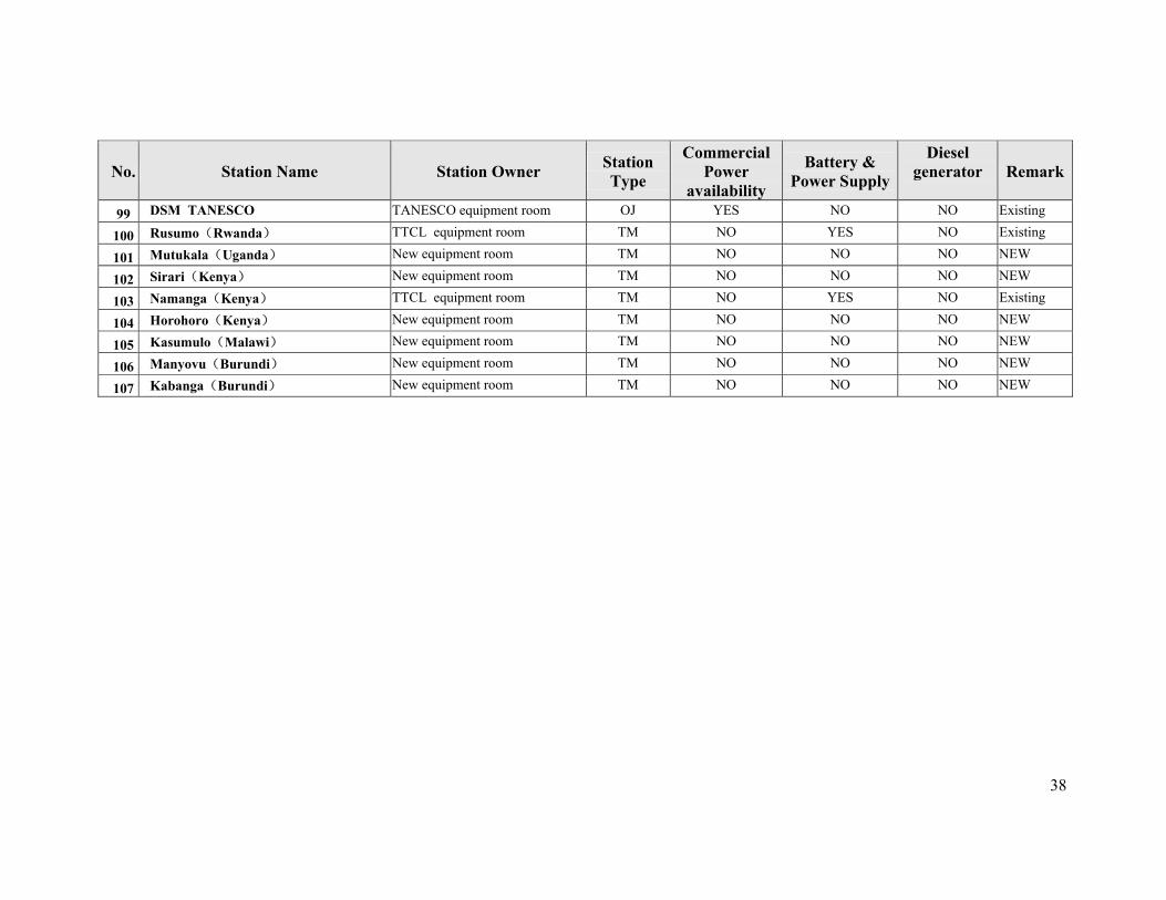
38
No. Station Name Station Owner Station Type
Commercial Power
availability
Battery & Power Supply
Diesel generator
Remark
99 DSM TANESCO TANESCO equipment room OJ YES NO NO Existing
100 Rusumo(Rwanda) TTCL equipment room TM NO YES NO Existing
101 Mutukala(Uganda) New equipment room TM NO NO NO NEW
102 Sirari(Kenya) New equipment room TM NO NO NO NEW
103 Namanga(Kenya) TTCL equipment room TM NO YES NO Existing
104 Horohoro(Kenya) New equipment room TM NO NO NO NEW
105 Kasumulo(Malawi) New equipment room TM NO NO NO NEW
106 Manyovu(Burundi) New equipment room TM NO NO NO NEW
107 Kabanga(Burundi) New equipment room TM NO NO NO NEW
39
3.3 OFC Line Plant
3.3.1 OFC Route Selection Criteria Routing of the OFC lines have been selected based on the following:
(1) To satisfy requirement to reach all regional HQ and major centers
(2) To allow easy and cost effective extension of tail links to small towns and rural
areas
(3) Existence of OFC along electricity high tension pylons and railways
(4) To follow major roads for easy of accessibility
(5) To maximize utilization of existing resources such as equipment rooms, power
supply
(6) Realization of easy interconnection to the existing telecom centers
Roads and Railway lines reach to many areas of the country so they have greatly influenced
routing of the optical cable. Optical fibre cable is generally constructed along the highway
and railway in the many circumstances due to availability of way leaves and easy of
accessibility to sites.
3.3.2 OFC Capacity
The capacity and quantity of the OFC proposed under this project have been arrived at by
considering the following factors:
(1) Based on the forecasted demand
(2) To satisfy requirements of all users in Tanzania
(3) To provide spare capacity for future uses and take care of emerging new
services such as data and image and multimedia
(4) To allow smooth upgrades of the transmission systems.
(5) To provide adequate capacity for domestic and international applications.
(6) To provide high level of network resiliency, redundancy and reliability for
offering quality services.
(7) On construction and maintenance consideration aspects, requirement for quick
repair during breakdown, fast development in the optical fibre technology, OFC
structure, and cost aspects; it is recommended that the number of cores in a
single cable need not be too large.
40
With regard to the above factors, it is recommended that the planned OFC network should
have 48 cores while the links to borders with neighboring countries should be of 24 cores.
Wherever the existing OFC line laid with 24 cores, then line will not be rebuilt, but when the
existing OFC line is less than 24 cores, then the line will be needed to be rebuilt or upgraded.
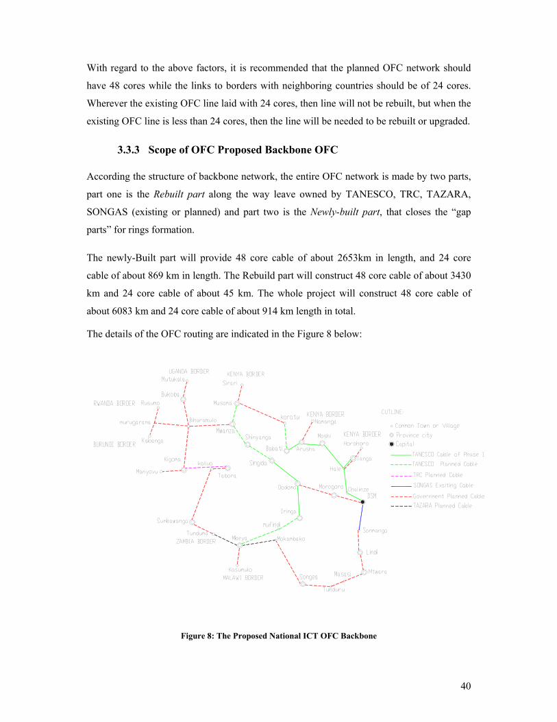
3.3.3 Scope of OFC Proposed Backbone OFC According the structure of backbone network, the entire OFC network is made by two parts,
part one is the Rebuilt part along the way leave owned by TANESCO, TRC, TAZARA,
SONGAS (existing or planned) and part two is the Newly-built part, that closes the “gap
parts” for rings formation.
The newly-Built part will provide 48 core cable of about 2653km in length, and 24 core
cable of about 869 km in length. The Rebuild part will construct 48 core cable of about 3430
km and 24 core cable of about 45 km. The whole project will construct 48 core cable of
about 6083 km and 24 core cable of about 914 km length in total.
The details of the OFC routing are indicated in the Figure 8 below:
Figure 8: The Proposed National ICT OFC Backbone

41
a) The re-build Part The rebuilt part deals with two categories of OFC construction works:
(i) Category 1
Categories 1will have three situations of OFC construction works:
Situation 1:
Construction of OFC closing links (tie links) on the existing OFC links with 24 cores for
extention to backbone network – newly built (TANESCO phase-1, SONGAS Somanga-
Mtwara, Karatu-Musoma links).
Situation 2:
Construction of 48 cores cable on the existing OFC with insufficient cores - 6 cores DSM –
Morogoro link and 8 cores Morogoro-Dodoma link both belonging to TRC
Situation 3:
Construction of 48 cores on links originally planned with 24 cores (TANESCO phase 2,
TRC planned, TAZARA planned). Ref Table 3.3.1.
42
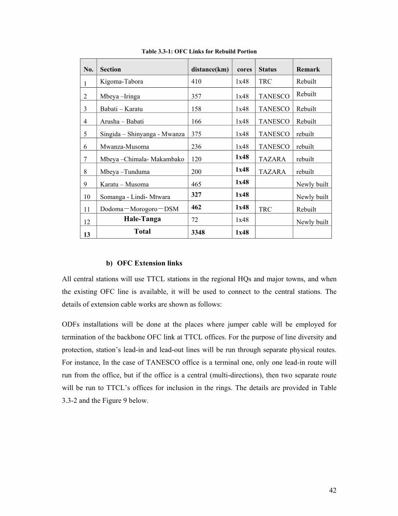
Table 3.3-1: OFC Links for Rebuild Portion
No. Section distance(km) cores Status Remark
1 Kigoma-Tabora 410 1x48 TRC Rebuilt
2 Mbeya –Iringa 357 1x48 TANESCO Rebuilt
3 Babati – Karatu 158 1x48 TANESCO Rebuilt
4 Arusha – Babati 166 1x48 TANESCO Rebuilt
5 Singida – Shinyanga - Mwanza 375 1x48 TANESCO rebuilt
6 Mwanza-Musoma 236 1x48 TANESCO rebuilt
7 Mbeya –Chimala- Makambako 120 1x48 TAZARA rebuilt
8 Mbeya –Tunduma 200 1x48 TAZARA rebuilt
9 Karatu – Musoma 465 1x48 Newly built
10 Somanga - Lindi- Mtwara 327 1x48 Newly built
11 Dodoma-Morogoro-DSM 462 1x48 TRC Rebuilt
12 Hale-Tanga 72 1x48 Newly built
13 Total 3348 1x48
b) OFC Extension links
All central stations will use TTCL stations in the regional HQs and major towns, and when
the existing OFC line is available, it will be used to connect to the central stations. The
details of extension cable works are shown as follows:
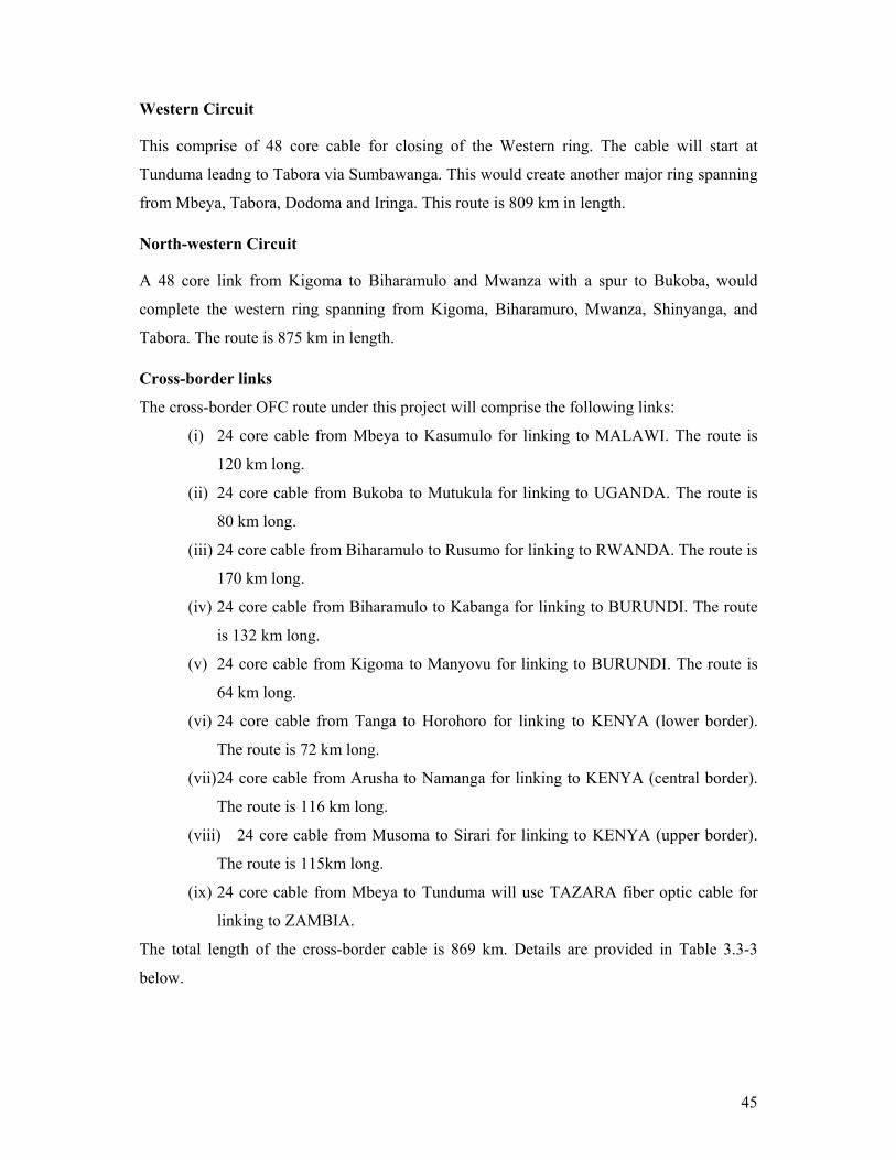
ODFs installations will be done at the places where jumper cable will be employed for
termination of the backbone OFC link at TTCL offices. For the purpose of line diversity and
protection, station’s lead-in and lead-out lines will be run through separate physical routes.
For instance, In the case of TANESCO office is a terminal one, only one lead-in route will
run from the office, but if the office is a central (multi-directions), then two separate route
will be run to TTCL’s offices for inclusion in the rings. The details are provided in Table
3.3-2 and the Figure 9 below.
43
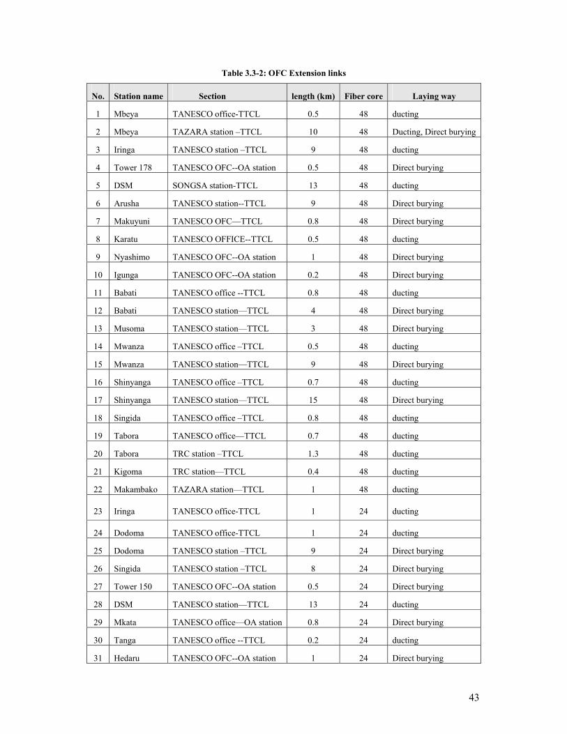
Table 3.3-2: OFC Extension links
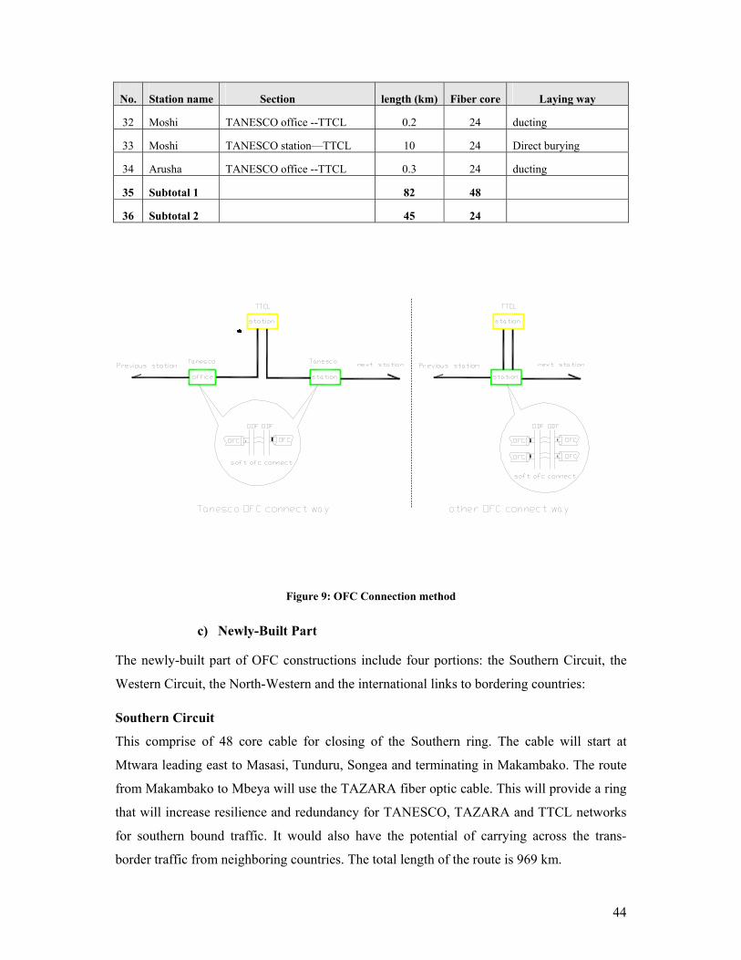
No. Station name Section length (km) Fiber core Laying way
1 Mbeya TANESCO office-TTCL 0.5 48 ducting
2 Mbeya TAZARA station –TTCL 10 48 Ducting, Direct burying
3 Iringa TANESCO station –TTCL 9 48 ducting
4 Tower 178 TANESCO OFC--OA station 0.5 48 Direct burying
5 DSM SONGSA station-TTCL 13 48 ducting
6 Arusha TANESCO station--TTCL 9 48 Direct burying
7 Makuyuni TANESCO OFC—TTCL 0.8 48 Direct burying
8 Karatu TANESCO OFFICE--TTCL 0.5 48 ducting
9 Nyashimo TANESCO OFC--OA station 1 48 Direct burying
10 Igunga TANESCO OFC--OA station 0.2 48 Direct burying
11 Babati TANESCO office --TTCL 0.8 48 ducting
12 Babati TANESCO station—TTCL 4 48 Direct burying
13 Musoma TANESCO station—TTCL 3 48 Direct burying
14 Mwanza TANESCO office –TTCL 0.5 48 ducting
15 Mwanza TANESCO station—TTCL 9 48 Direct burying
16 Shinyanga TANESCO office –TTCL 0.7 48 ducting
17 Shinyanga TANESCO station—TTCL 15 48 Direct burying
18 Singida TANESCO office –TTCL 0.8 48 ducting
19 Tabora TANESCO office—TTCL 0.7 48 ducting
20 Tabora TRC station –TTCL 1.3 48 ducting
21 Kigoma TRC station—TTCL 0.4 48 ducting
22 Makambako TAZARA station—TTCL 1 48 ducting
23 Iringa TANESCO office-TTCL 1 24 ducting
24 Dodoma TANESCO office-TTCL 1 24 ducting
25 Dodoma TANESCO station –TTCL 9 24 Direct burying
26 Singida TANESCO station –TTCL 8 24 Direct burying
27 Tower 150 TANESCO OFC--OA station 0.5 24 Direct burying
28 DSM TANESCO station—TTCL 13 24 ducting
29 Mkata TANESCO office—OA station 0.8 24 Direct burying
30 Tanga TANESCO office --TTCL 0.2 24 ducting
31 Hedaru TANESCO OFC--OA station 1 24 Direct burying
44
No. Station name Section length (km) Fiber core Laying way
32 Moshi TANESCO office --TTCL 0.2 24 ducting
33 Moshi TANESCO station—TTCL 10 24 Direct burying
34 Arusha TANESCO office --TTCL 0.3 24 ducting
35 Subtotal 1 82 48
36 Subtotal 2 45 24
Figure 9: OFC Connection method
c) Newly-Built Part
The newly-built part of OFC constructions include four portions: the Southern Circuit, the
Western Circuit, the North-Western and the international links to bordering countries:
Southern Circuit
This comprise of 48 core cable for closing of the Southern ring. The cable will start at
Mtwara leading east to Masasi, Tunduru, Songea and terminating in Makambako. The route
from Makambako to Mbeya will use the TAZARA fiber optic cable. This will provide a ring
that will increase resilience and redundancy for TANESCO, TAZARA and TTCL networks
for southern bound traffic. It would also have the potential of carrying across the trans-
border traffic from neighboring countries. The total length of the route is 969 km.
45
Western Circuit
This comprise of 48 core cable for closing of the Western ring. The cable will start at
Tunduma leadng to Tabora via Sumbawanga. This would create another major ring spanning
from Mbeya, Tabora, Dodoma and Iringa. This route is 809 km in length.
North-western Circuit
A 48 core link from Kigoma to Biharamulo and Mwanza with a spur to Bukoba, would
complete the western ring spanning from Kigoma, Biharamuro, Mwanza, Shinyanga, and
Tabora. The route is 875 km in length.
Cross-border links
The cross-border OFC route under this project will comprise the following links:
(i) 24 core cable from Mbeya to Kasumulo for linking to MALAWI. The route is
120 km long.
(ii) 24 core cable from Bukoba to Mutukula for linking to UGANDA. The route is
80 km long.
(iii) 24 core cable from Biharamulo to Rusumo for linking to RWANDA. The route is
170 km long.
(iv) 24 core cable from Biharamulo to Kabanga for linking to BURUNDI. The route
is 132 km long.
(v) 24 core cable from Kigoma to Manyovu for linking to BURUNDI. The route is
64 km long.
(vi) 24 core cable from Tanga to Horohoro for linking to KENYA (lower border).
The route is 72 km long.
(vii) 24 core cable from Arusha to Namanga for linking to KENYA (central border).
The route is 116 km long.
(viii) 24 core cable from Musoma to Sirari for linking to KENYA (upper border).
The route is 115km long.
(ix) 24 core cable from Mbeya to Tunduma will use TAZARA fiber optic cable for
linking to ZAMBIA.
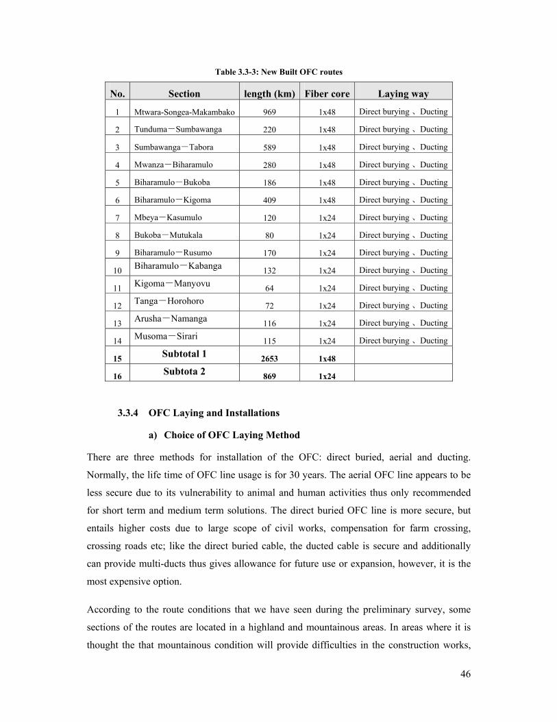
The total length of the cross-border cable is 869 km. Details are provided in Table 3.3-3
below.
46
Table 3.3-3: New Built OFC routes
No. Section length (km) Fiber core Laying way
1 Mtwara-Songea-Makambako 969 1x48 Direct burying 、Ducting
2 Tunduma-Sumbawanga 220 1x48 Direct burying 、Ducting
3 Sumbawanga-Tabora 589 1x48 Direct burying 、Ducting
4 Mwanza-Biharamulo 280 1x48 Direct burying 、Ducting
5 Biharamulo-Bukoba 186 1x48 Direct burying 、Ducting
6 Biharamulo-Kigoma 409 1x48 Direct burying 、Ducting
7 Mbeya-Kasumulo 120 1x24 Direct burying 、Ducting
8 Bukoba-Mutukala 80 1x24 Direct burying 、Ducting
9 Biharamulo-Rusumo 170 1x24 Direct burying 、Ducting
10 Biharamulo-Kabanga 132 1x24 Direct burying 、Ducting
11 Kigoma-Manyovu 64 1x24 Direct burying 、Ducting
12 Tanga-Horohoro 72 1x24 Direct burying 、Ducting
13 Arusha-Namanga 116 1x24 Direct burying 、Ducting
14 Musoma-Sirari 115 1x24 Direct burying 、Ducting
15 Subtotal 1 2653 1x48
16 Subtota 2 869 1x24
3.3.4 OFC Laying and Installations
a) Choice of OFC Laying Method
There are three methods for installation of the OFC: direct buried, aerial and ducting.
Normally, the life time of OFC line usage is for 30 years. The aerial OFC line appears to be
less secure due to its vulnerability to animal and human activities thus only recommended
for short term and medium term solutions. The direct buried OFC line is more secure, but
entails higher costs due to large scope of civil works, compensation for farm crossing,
crossing roads etc; like the direct buried cable, the ducted cable is secure and additionally
can provide multi-ducts thus gives allowance for future use or expansion, however, it is the
most expensive option.
According to the route conditions that we have seen during the preliminary survey, some
sections of the routes are located in a highland and mountainous areas. In areas where it is
thought the that mountainous condition will provide difficulties in the construction works,
47
TANESCO power pylons will be used for carrying the OFC and this case it means adoption
to aerial method through high-tension transmission.
Direct buried cable method is suggested for adoption in areas where the land is relatively flat
and of average soil condition. The direct buried routes are selected to follow the main roads,
through villages and are negotiated carefully to easy accessibility & construction works
across the woodland, forest and rock mountainous areas. In average buried cable route is
placed at about 100-200m in length away from the roads. In case of odd soil conditions
sections like hard rock or difficult mountains, the aerial method is opted for the cable
construction.
In the urban areas, ductwork system will be adopted for laying the OFC lines and has been
noted that TTCL has existing duct systems in almost every urban ship therefore it is better to
make the most use of it for installation of the OFC backbone. Wherever the existing ducts
will need modifications or expansion, then PVC plastic pipes may be adopted. For OFC
going through small villages or small townships, it is recommended to use direct buried
cable method.
b) PVC Pipe Line Capacity and Construction Scope
Due to diversified possible use of the OFC lines i.e , there leased dark fibre or wave length
for private / corporate use and possible future cable upgrades, there is need to allow for
provision of atleast spare PVC plastic pipe duct capacity along the backbone duct sections.
In this project, 20km of 4 PVC pipe duct system is recommended for DSM area. Likewise
for the other four (4) zonal cities of MWANZA, ARUSHA, MBEYA and DODOMA, 10km
of 4 PVC pipe duct system is recommended. And for other remaining municipalities and
towns, 6km of 4 PVC pipe duct system is proposed. In small towns, 2km of 2 PVC pipe duct
system will be adequate. In total 700 km of PVC duct system will be constructed under this
project. The exactly scope of the duct construction works and the relative technical
requirements will be discussed in the detail during detail design phase.
c) Optical Cable Line Protection
Some protection measures will have to be employed in order to cancel effects of any
undesirable induction due to electrical and electromagnetic fields. In this case though the
cable will have no metal conductors/pairs, some metal components are inherent in the cable
mechanics and thus the following protection measures will be employed in the design stage
in order to cancel the effect of the electromagnetic inductions:
48
(i) Anti- lightning strike
Besides suffering from direct effect of lightning strike hit, the cable line is also vulnerable to
the effect of electric arc and ground potential difference caused by the strike. When the strike
current exceeds the designed intensity destructive damage to the cable and equipment can be
sustained. The anti-strike measures can be applied under such situations to mitigate its
destructive effect. Detail information on the strike protection method will be provided in the
detail design stage
(ii) Damp proof
Fiber optical cable is generally vulnerable to wear and erosion if subject for a long time to
damp or water-logged condition. In effect the cable performance will degrade progressively
with time by increased transmission attenuation and hence reduced its designed lifetime
significantly. As protection to such effects, damp proof layer or shield and jelly-filler
measures are employed.
d) Optical Cable Specifications
(i) G.652 optical fibre
a. Single-mode optical fibre recommended by ITU-T
b. Mode field diameter (wavelength of 1310nm,defined by Peterman)
• Standard value:getting one between 8.6 and 9.5µm
• Difference:not exceeding ±0.7µm
c. Cladding diameter
1. Standard value:125.0µm
2. Difference:not exceeding ±1µm
d. Concentric difference based on the wavelength of 1310nm:
• not more than 0.8µm
e. Non-concentric extent of fiber cladding:less than 2.0%
f. Fibre curl extent: curvature radius of 4.0m
g. Fiber cutoff wavelength fiber cutoff wavelength should meet the
requirement of the λcc as below:
• λcc(test with 20 meter optical cable plus 2 meter fibre):
≤1260nm
49
h. Fiber attenuation coefficient
• Largest fiber attenuation coefficient based on wavelength of
1310nm 0.36dB/km
By comparison, the difference of the attenuation coefficient based
on the wavelength of 1310nm and any other wavelength which is
between 1285-1330nm should not exceed 0.03dB/km.
• Maximal attenuation value of the wavelength of 1550nm is
0.22dB/km.
By comparison, the difference of the attenuation coefficient based
on the wavelength of 1550nm and any other wavelength which is
between 1480-1580nm should not exceed 0.05dB/km.
• Fiber attenuation curve should be of good linearity and have no
distinct step. The attenuation value of any 500-meter-long fiber
tested by OTDR based on the wavelength of 1310nm and 1550nm
should not exceed (α mean +0.10dB)/2,α mean is the average
attenuation coefficient of fiber.
i. Curve attenuation characteristic of the fibre based on the wavelength of
1550nm and 1625nm. The maximal attenuation value of fiber G.652A at
the window of 1550nm is 0.50dB when coiled loosely by 100 circles with
the bending radius of 30 mm,Maximal attenuation value of fiber
G.652B and G.652C at the window of 1625nm is also 0.50dB. Maximal
attenuation value of G.652D fiber at the window of 1625nm is 0.50dB.
j. Dispersion
The range of zero dispersion wavelength is 1300-1324nm;
The slope of maximal zero dispersion should not exceed 0.093ps/
(nm2.km).
k. Polarization Mode Dispersion
Polarization Mode Dispersion coefficient of one reel of cable at the window
of 1550nmshould not exceed 0.20ps/√km;Polarization Mode Dispersion
of optical cable line (≥20 reel)should not exceed 0.15ps/√km。
l. Tensile filtering experiment
All of the one-off coating fiber must be tested by tensile filtering experiment
before being made into optical cable. The pull should not be less than 8.2N
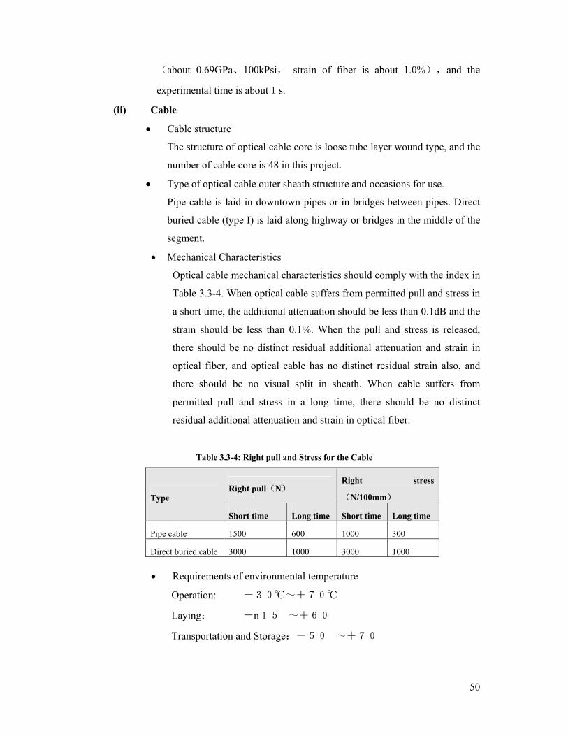
50
(about 0.69GPa、100kPsi, strain of fiber is about 1.0%),and the
experimental time is about1s.
(ii) Cable
• Cable structure
The structure of optical cable core is loose tube layer wound type, and the
number of cable core is 48 in this project.
• Type of optical cable outer sheath structure and occasions for use.
Pipe cable is laid in downtown pipes or in bridges between pipes. Direct
buried cable (type I) is laid along highway or bridges in the middle of the
segment.
• Mechanical Characteristics
Optical cable mechanical characteristics should comply with the index in
Table 3.3-4. When optical cable suffers from permitted pull and stress in
a short time, the additional attenuation should be less than 0.1dB and the
strain should be less than 0.1%. When the pull and stress is released,
there should be no distinct residual additional attenuation and strain in
optical fiber, and optical cable has no distinct residual strain also, and
there should be no visual split in sheath. When cable suffers from
permitted pull and stress in a long time, there should be no distinct
residual additional attenuation and strain in optical fiber.
Table 3.3-4: Right pull and Stress for the Cable
Right pull(N) Right stress
(N/100mm) Type
Short time Long time Short time Long time
Pipe cable 1500 600 1000 300
Direct buried cable 3000 1000 3000 1000
• Requirements of environmental temperature
Operation: -30~+70
Laying: -n15~+60
Transportation and Storage:-50~+70
51
• Reel length of optical cable
Optical cable standard length of one reel is 3000m and 2000m.
• Standard thickness of outer plastic sheath of optical cable is more than
2.0mm.
• Optical cable PE sheath insulation resistance
Tested after having dipped in water for 24 hours, the insulation
resistance of optical cable sheath should not be less than 2000MΩ.km
(tested by 500v direct current)
• Dielectric strength
After dipped in water for 24 hours, dielectric strength of the outer sheath
which is between steel tape and earth will not be less than 15KV 2minute
in direct current. And dielectric strength which is between steel tape and
the metal strong core will not be less than 20KV 5second in direct current.
• Other
For reconstruct part of TENESCO, it depends on the status of different
using, to choice OPGW or ADSS.
3.4 Associated Construction Works Requirement
3.4.1 Requirement of Telecom Station
a) Equipment Room Condition
(i) Indoor requirements:
Permanently air conditioned maintained to the following conditions:
a. Temperature: 25±2;
b. Relative Humidity: 45%~65%;
c. Variation Rate of Temperature: <5/h,without the dew coming into being;
d. Anti-dust: the quantities of dust specks in the air tested on the static state should be
less than 18000 speck per litre.
(ii) Outdoor requirements:
Resistible to burning, non-explosive items, non-volatile gas, non-susceptible to strong
electromagnetism field, strong to vibrations or strong noises pollutions with source near the
equipment room and any factor which will harm the normal operation of the system should
be found and avoided.
52
(iii) Floor Height:
The height of the floor of the house should comply with the standard on which the machine
with a height of 2200mm or 2000mm can be installed; the practicable height of the room
should be no less than 3meters.
(iv) Floor Load Bearing Capacity:
The floor should be capable handling load of at least 600 Kg/m2 with the machine installed
in the house arranged by the mode of face to back or back to back; the loading of the floor
should be at least 800Kg/ m2 with the accumulator installed in;
(v) Inside Fitness:
The fitments inside the room should conform to the requirement for installation of
communication equipments, and it is recommended to use durable materials, anti-dust, anti-
slide and non-burning materials. Not allowed to use the materials such as wood floor and
suspended ceiling and plastics. Some measure should be taken on hole be well sealed: anti-
fire, anti-wet or anti-bugs;
(vi) Safety & Fire Control:
Safety and Fire control measures should conform to the Safety Regulations & provisions in
place for buildings;
(vii) Grounding Requirement:
Common grounding for building and equipment is recommended for proper protection
against lightning. The grounding resistance should be less than 1 ohm.
3.4.2 Requirement for Power Supply System A power supply system for telecom equipments must be safe and reliable. Power supply is
the key component on operation of telecommunication equipments. The power supply
quality will directly influence performance of the communication network, thus in order to
ensure availability of communication services the power supply must work prudently within
the specified limits and with high level of availability.
For this project, detailed information of status of all surveyed stations is provided as follows:
(i) All TTCL’s major stations have Commercial power, standby diesel generators
and Rectifier and backup batteries. For the remote microwave station where there
is no commercial power, TTLL have adopted use of solar power systems.
53
(ii) TANESCO uses Commercial power supply for equipment in all stations. TRC
and TAZARA employ solar power system for their remote stations.
Under this project, use of existing power systems is opted wherever the power system has
adequate spare capacity. In case the existing power supply system in not adequate there is
need add separate power equipment however, the capacity of the new power supply
equipment is dimensioned for equipment under this project only.
a) Types of Power Supply system There three kinds of power supply works considered for this project depending on situation
of each station:
(i) Integrating to existing Power supply system
In case of availability of commercial power and existing standby generator, new
power installation will cover provision of new Rectifier & Batteries. The new power
equipment will be integrated to the existing AC power sources. This scenario is
typical of many TTCL stations.
(ii) Provision of Mini-type Power Supply System
The scope of power equipment provision for new stations will include connection to
commercial power if available, new generator, new rectifier & batteries, such type
of power system is typical of TTCL and TANESCO stations.
(iii) Provision of Solar Power Supply System
For solar power stations, the scope of power supply equipment will entail provision
of complete new solar power supply system, consisting of solar panels, batteries and
regulator. The scenario is typical for remote stations belonging to TTCL, TRC and
TAZARA. Detailed requirement for power supply installations under this project is
given in table 3.4-1 below:
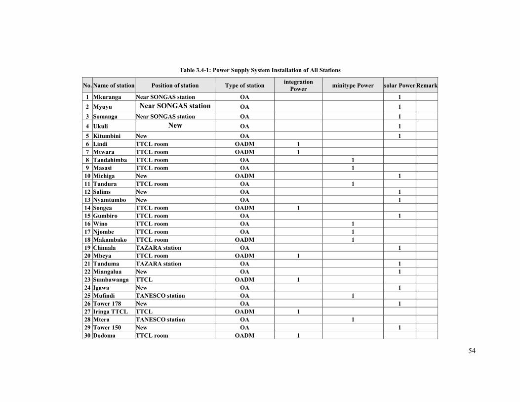
54
Table 3.4-1: Power Supply System Installation of All Stations
No. Name of station Position of station Type of station integration Power minitype Power solar PowerRemark
1 Mkuranga Near SONGAS station OA 1 2 Myuyu Near SONGAS station OA 1 3 Somanga Near SONGAS station OA 1 4 Ukuli New OA 1 5 Kitumbini New OA 1 6 Lindi TTCL room OADM 1 7 Mtwara TTCL room OADM 1 8 Tandahimba TTCL room OA 1 9 Masasi TTCL room OA 1
10 Michiga New OADM 1 11 Tundura TTCL room OA 1 12 Salims New OA 1 13 Nyamtumbo New OA 1 14 Songea TTCL room OADM 1 15 Gumbiro TTCL room OA 1 16 Wino TTCL room OA 1 17 Njombe TTCL room OA 1 18 Makambako TTCL room OADM 1 19 Chimala TAZARA station OA 1 20 Mbeya TTCL room OADM 1 21 Tunduma TAZARA station OA 1 22 Miangalua New OA 1 23 Sumbawanga TTCL OADM 1 24 Igawa New OA 1 25 Mufindi TANESCO station OA 1 26 Tower 178 New OA 1 27 Iringa TTCL TTCL OADM 1 28 Mtera TANESCO station OA 1 29 Tower 150 New OA 1 30 Dodoma TTCL room OADM 1
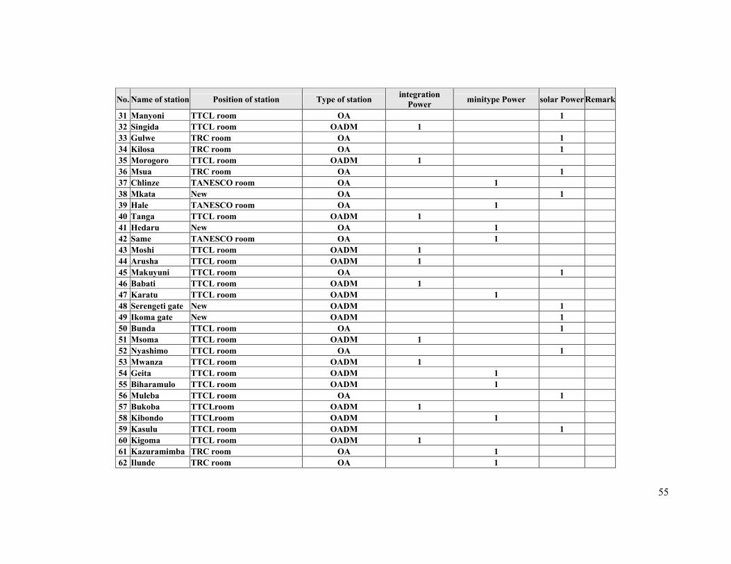
55
No. Name of station Position of station Type of station integration Power minitype Power solar PowerRemark
31 Manyoni TTCL room OA 1 32 Singida TTCL room OADM 1 33 Gulwe TRC room OA 1 34 Kilosa TRC room OA 1 35 Morogoro TTCL room OADM 1 36 Msua TRC room OA 1 37 Chlinze TANESCO room OA 1 38 Mkata New OA 1 39 Hale TANESCO room OA 1 40 Tanga TTCL room OADM 1 41 Hedaru New OA 1 42 Same TANESCO room OA 1 43 Moshi TTCL room OADM 1 44 Arusha TTCL room OADM 1 45 Makuyuni TTCL room OA 1 46 Babati TTCL room OADM 1 47 Karatu TTCL room OADM 1 48 Serengeti gate New OADM 1 49 Ikoma gate New OADM 1 50 Bunda TTCL room OA 1 51 Msoma TTCL room OADM 1 52 Nyashimo TTCL room OA 1 53 Mwanza TTCL room OADM 1 54 Geita TTCL room OADM 1 55 Biharamulo TTCL room OADM 1 56 Muleba TTCL room OA 1 57 Bukoba TTCLroom OADM 1 58 Kibondo TTCLroom OADM 1 59 Kasulu TTCL room OADM 1 60 Kigoma TTCL room OADM 1 61 Kazuramimba TRC room OA 1 62 Ilunde TRC room OA 1
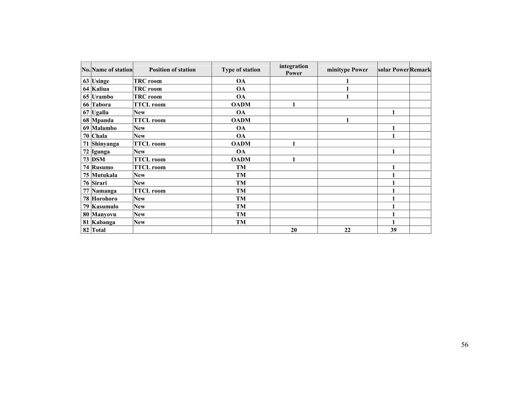
56
No. Name of station Position of station Type of station integration Power minitype Power solar PowerRemark
63 Usinge TRC room OA 1 64 Kaliua TRC room OA 1 65 Urambo TRC room OA 1 66 Tabora TTCL room OADM 1 67 Ugalla New OA 1 68 Mpanda TTCL room OADM 1 69 Malambo New OA 1 70 Chala New OA 1 71 Shinyanga TTCL room OADM 1 72 Igunga New OA 1 73 DSM TTCL room OADM 1 74 Rusumo TTCL room TM 1 75 Mutukala New TM 1 76 Sirari New TM 1 77 Namanga TTCL room TM 1 78 Horohoro New TM 1 79 Kasumulo New TM 1 80 Manyovu New TM 1 81 Kabanga New TM 1 82 Total 20 22 39
57
3.4.3 Power Supply Supervision System
All power supply equipments need to be supervised remotely from the central monitoring
station. Under this project, alarm signals of different power equipment (solar batteries,
rectifiers, batteries and so on) and other house keeping alarm signals will be relayed to the
maintenance centre through supervision system for monitoring purpose.
3.4.4 Construction of OFC Duct System
a) Requirement of Ductwork Routes
(i) Duct routes should avoid to be constructed along temporary road, along roads
under construction, or along soft (non-compacted) road.
(ii) Duct pipes should be constructed away from contaminated canal with erosive
chemicals.
(iii) Clear streets with few barriers (underground and above ground) could be the
better choice for the construction.
(iv) Precautions should be made when constructing duct routes on the same side of
the road with combustible gas-pipes and high voltage power lines, and if that can
not be avoided then they should keep a fair distance with one another.
b) Locations of Ductwork Routes
(i) The ductwork systems should be constructed within pavement of town streets,
and if it is impossible for them to be constructed within the pavement, they may
be put under the slow driveway and not under the fast driveway.
(ii) If ductworks are done along highways, then ducts should be constructed within
the isolation zone.
(iii) The center line along pipes routes should be parallel with the center line of roads.
(iv) Communication duct pipes lines should not be constructed near each other, if
necessitate be in same route then they should be separated by reasonable
difference in depth.
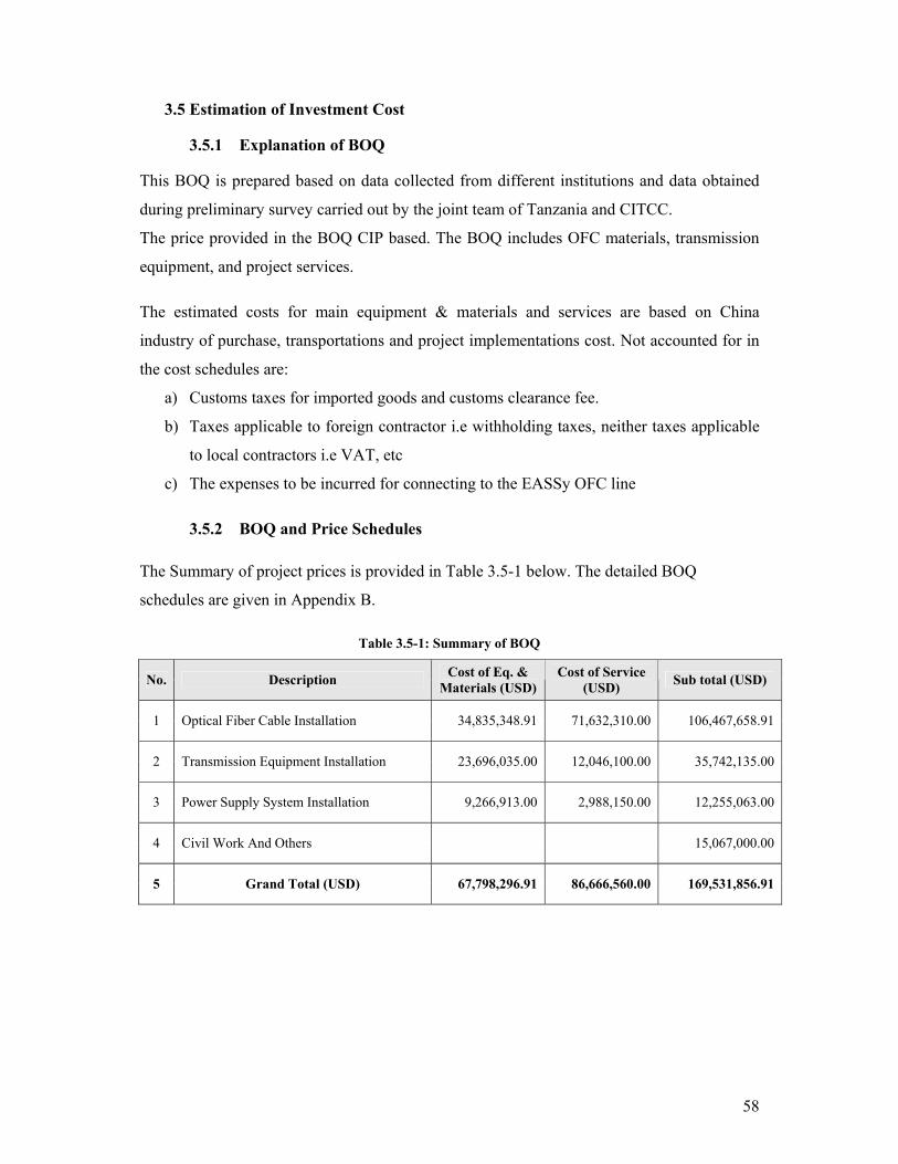
58
3.5 Estimation of Investment Cost
3.5.1 Explanation of BOQ
This BOQ is prepared based on data collected from different institutions and data obtained
during preliminary survey carried out by the joint team of Tanzania and CITCC.
The price provided in the BOQ CIP based. The BOQ includes OFC materials, transmission
equipment, and project services.
The estimated costs for main equipment & materials and services are based on China
industry of purchase, transportations and project implementations cost. Not accounted for in
the cost schedules are:
a) Customs taxes for imported goods and customs clearance fee.
b) Taxes applicable to foreign contractor i.e withholding taxes, neither taxes applicable
to local contractors i.e VAT, etc
c) The expenses to be incurred for connecting to the EASSy OFC line
3.5.2 BOQ and Price Schedules The Summary of project prices is provided in Table 3.5-1 below. The detailed BOQ
schedules are given in Appendix B.
Table 3.5-1: Summary of BOQ
No. Description Cost of Eq. & Materials (USD)
Cost of Service (USD) Sub total (USD)
1 Optical Fiber Cable Installation 34,835,348.91 71,632,310.00 106,467,658.91
2 Transmission Equipment Installation 23,696,035.00 12,046,100.00 35,742,135.00
3 Power Supply System Installation 9,266,913.00 2,988,150.00 12,255,063.00
4 Civil Work And Others 15,067,000.00
5 Grand Total (USD) 67,798,296.91 86,666,560.00 169,531,856.91

59
3.6 Proposed Implementation Schedule
This project is proposed for implementation in two logical stages done simultaneously for
the formation of fully functioning OFC backbone network. The total period for the whole
project is 24 months from the confirmation of funding.
Logical Stage 1:
Stage One will involve construction of major sections of Northern, Central and Southern
Routes. The details are shown in Table 3.6-1 and Table 3.6-2 below and Appendix A (4) at
the end of the report.
Logical Stage 2:
Stage Two will involve closing the Southern and Western OFC rings and shall cover routes
in Tables 3.6-3 & Table 3.6-4 and drawing No.5 of the Appendix A (5) in the end of the
report.
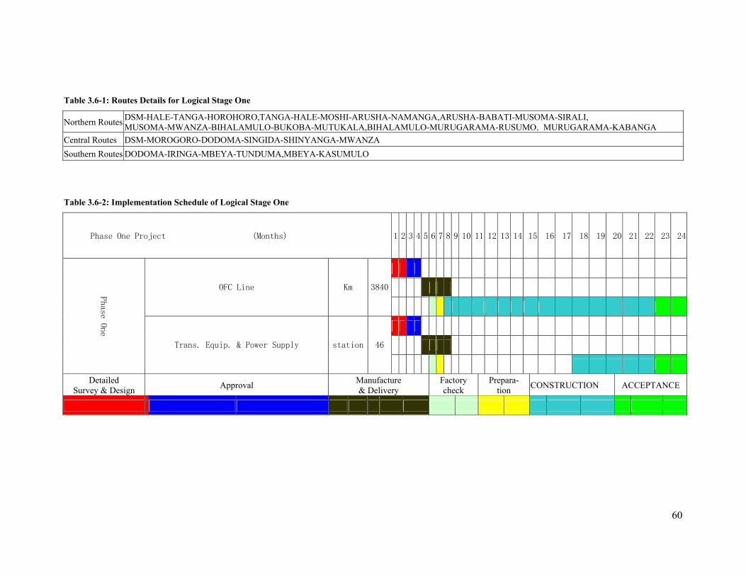
60
Table 3.6-1: Routes Details for Logical Stage One
Northern Routes DSM-HALE-TANGA-HOROHORO,TANGA-HALE-MOSHI-ARUSHA-NAMANGA,ARUSHA-BABATI-MUSOMA-SIRALI, MUSOMA-MWANZA-BIHALAMULO-BUKOBA-MUTUKALA,BIHALAMULO-MURUGARAMA-RUSUMO,MURUGARAMA-KABANGA
Central Routes DSM-MOROGORO-DODOMA-SINGIDA-SHINYANGA-MWANZA Southern Routes DODOMA-IRINGA-MBEYA-TUNDUMA,MBEYA-KASUMULO
Table 3.6-2: Implementation Schedule of Logical Stage One
Phase One Project (Months) 1 2 3 4 5 6 7 8 9 10 11 12 13 14 15 16 17 18 19 20 21 22 23 24
OFC Line Km 3840
Phase O
ne
Trans. Equip. & Power Supply station 46
Detailed Survey & Design Approval Manufacture
& Delivery Factory check
Prepara- tion CONSTRUCTION ACCEPTANCE
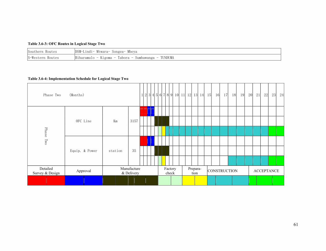
61
Table 3.6-3: OFC Routes in Logical Stage Two
Southern Routes DSM-Lindi- Mtwara- Songea- Mbeya
S-Western Routes Biharamulo - Kigoma - Tabora - Sumbawanga - TUNDUMA
Table 3.6-4: Implementation Schedule for Logical Stage Two
Phase Two (Months) 1 2 3 4 5 6 7 8 9 10 11 12 13 14 15 16 17 18 19 20 21 22 23 24
OFC Line Km 3157
Phas
e Two
Equip. & Power station 35
Detailed Survey & Design Approval Manufacture
& Delivery Factory check
Prepara- tion CONSTRUCTION ACCEPTANCE
62
4 CONCLUSION AND RECOMMENDATIONS
By considering the status of the existing national OFC networks and other required
resources, the Steering Committee has determined that practical implementation of the
National Backbone network is highly feasible. It is seen possible to achieve a fully fledged,
bandwidth rich national OFC network in the country by consolidating some segments of the
existing individual OFC networks belonging to the public institutions (TANESCO, TRC,
TAZARA, and SONGAS) and bridging the gaps to form the unified National OFC backbone
infrastructure. The national OFC backbone will be built on three main Optic Fibre Cable
(OFC) rings namely, the Northern ring, the Western ring and the Southern ring.
In the initial design of the backbone network, use of the latest bandwidth-rich transmission
technologies such as Dense Wavelength Division Multiplexing (DWDM) and Synchronous
Digital Hierarchy (SDH) have been proposed in order to guarantee ubiquitous capacity,
quality performance and unconstrained bandwidth for future use. This national OFC
backbone would form a “Carrier of Carriers” network providing bandwidth capacity to all
ICT service providers (fixed, mobile, voice, data, audio/ video broadcasting, multimedia)
including the Public Services Telecommunications Network (PSTN) operators. The
backbone network would support provision of Universal ICT Services Access to the whole
country by various service providers, competitively, in technology neutral environment and
providing various ICT services.
The total cost of the National ICT OFC backbone project is estimated at US$ 170m of which
US$ 107m are required for the Optic Fibre Cable portion, US$ 36m for provision of
transmission equipment, US$ 12m for power supply equipment and US$ 15m for civil and
other related works. The project can be implemented and completed within 24months period
from funding confirmation.

63
Based on these avails, Steering Committee have the following recommendations to the
Government of Tanzania:
(1) to consider and approve this report;
(2) to facilitate availability of the necessary funds and other resources for immediate
implementation of the National ICT Backbone Network; and
(3) To determine and mandate sustainable institutional arrangements for
management, operation and maintenance of the National OFC Backbone network.
5 APPENDICES
Appendix A: Network Drawings:
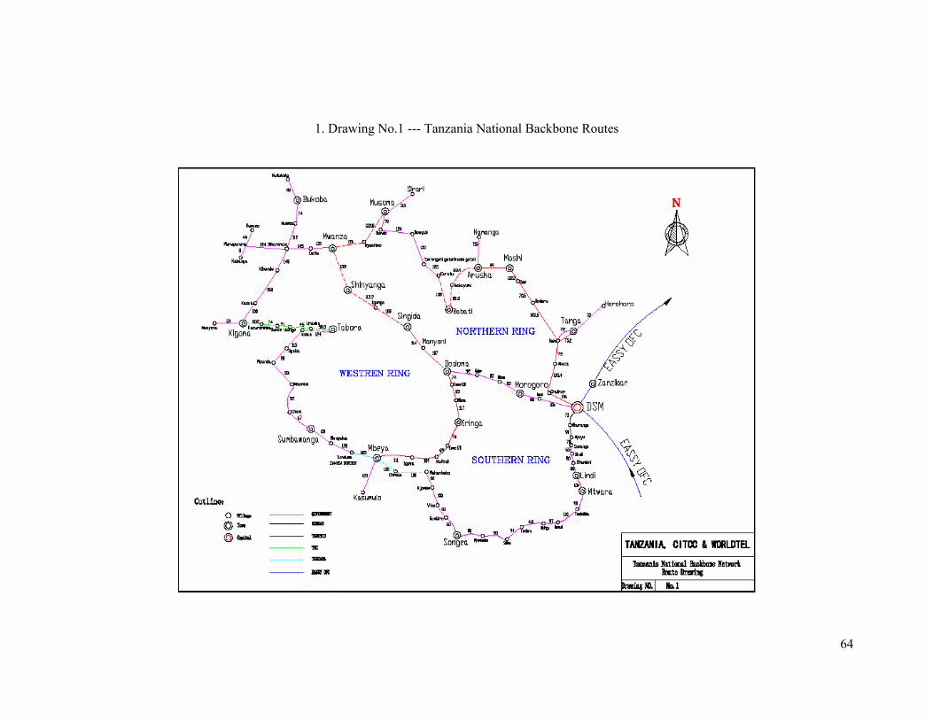
64
1. Drawing No.1 --- Tanzania National Backbone Routes
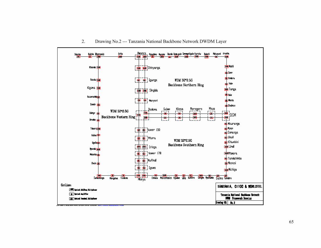
65
2. Drawing No.2 --- Tanzania National Backbone Network DWDM Layer
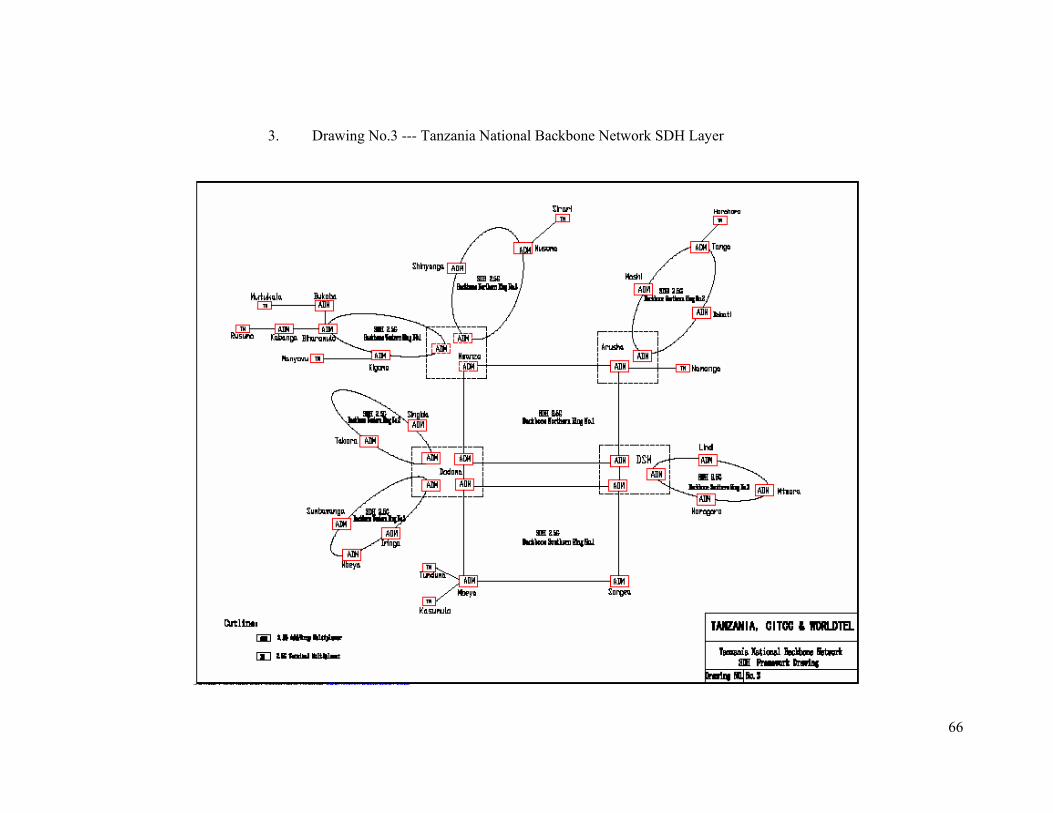
66
3. Drawing No.3 --- Tanzania National Backbone Network SDH Layer
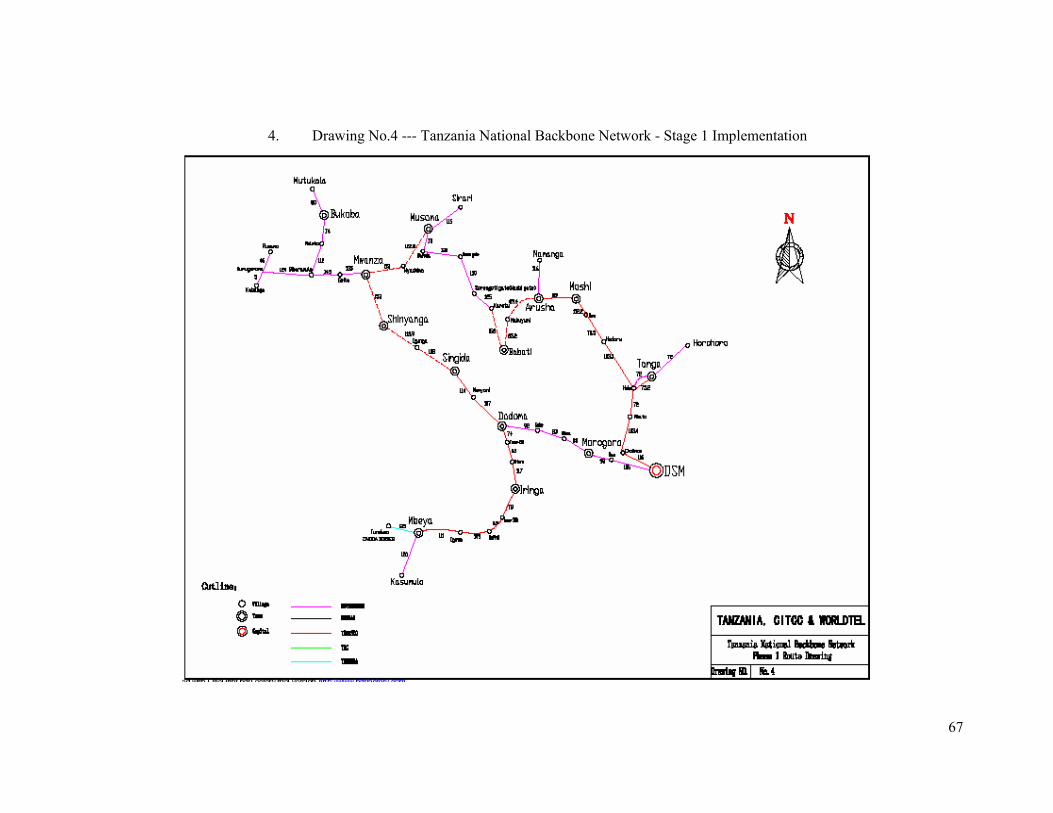
67
4. Drawing No.4 --- Tanzania National Backbone Network - Stage 1 Implementation
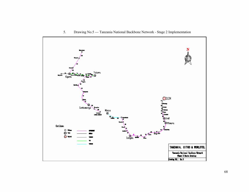
68
5. Drawing No.5 --- Tanzania National Backbone Network - Stage 2 Implementation
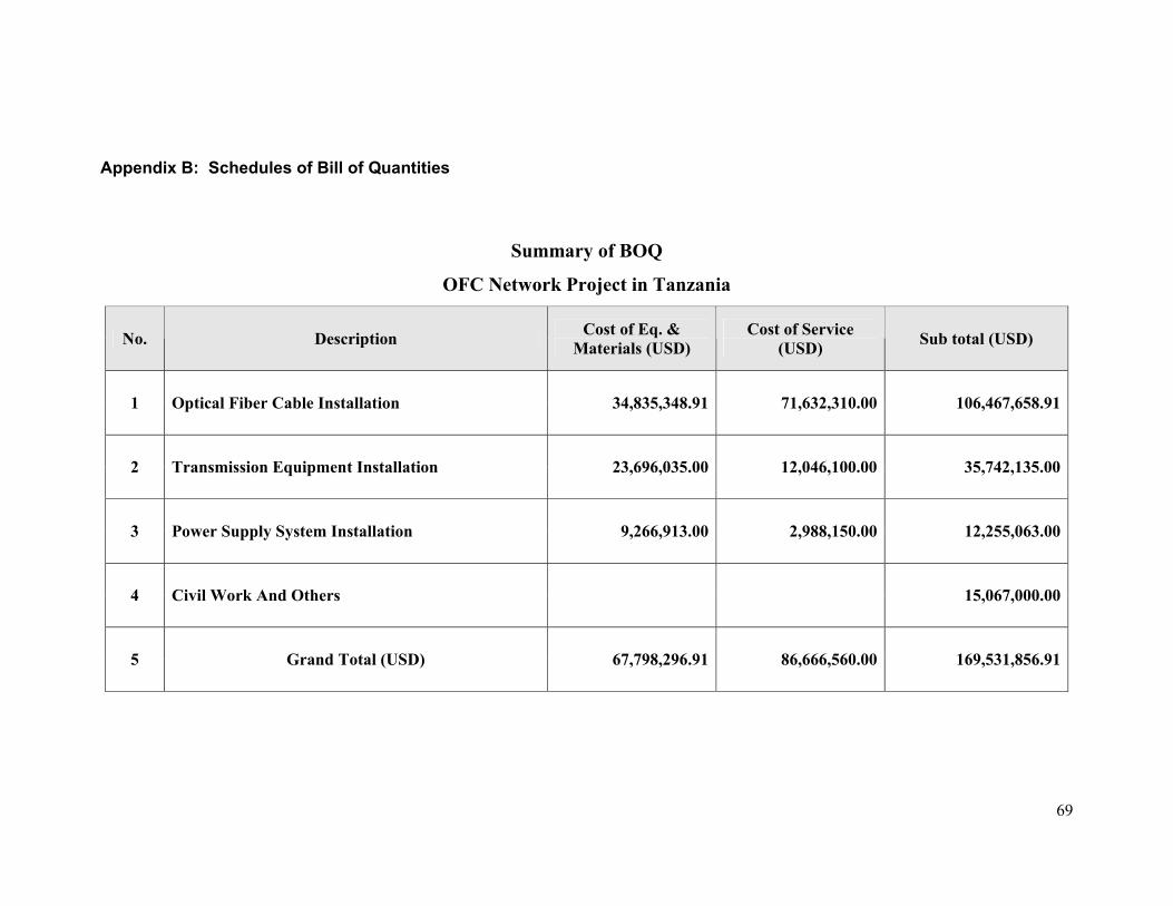
69
Appendix B: Schedules of Bill of Quantities
Summary of BOQ
OFC Network Project in Tanzania
No. Description Cost of Eq. & Materials (USD)
Cost of Service (USD) Sub total (USD)
1 Optical Fiber Cable Installation 34,835,348.91 71,632,310.00 106,467,658.91
2 Transmission Equipment Installation 23,696,035.00 12,046,100.00 35,742,135.00
3 Power Supply System Installation 9,266,913.00 2,988,150.00 12,255,063.00
4 Civil Work And Others 15,067,000.00
5 Grand Total (USD) 67,798,296.91 86,666,560.00 169,531,856.91
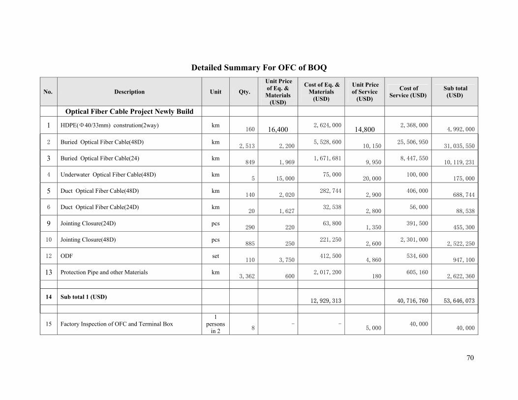
70
Detailed Summary For OFC of BOQ
No. Description Unit Qty.
Unit Price of Eq. & Materials
(USD)
Cost of Eq. & Materials
(USD)
Unit Price of Service
(USD)
Cost of Service (USD)
Sub total (USD)
Optical Fiber Cable Project Newly Build
1 HDPE(Φ40/33mm) constrution(2way) km
160
16,400 2,624,000
14,800 2,368,000
4,992,000
2 Buried Optical Fiber Cable(48D) km
2,513
2,200 5,528,600
10,150 25,506,950
31,035,550
3 Buried Optical Fiber Cable(24) km
849
1,969 1,671,681
9,950 8,447,550
10,119,231
4 Underwater Optical Fiber Cable(48D) km
5
15,000 75,000
20,000 100,000
175,000
5 Duct Optical Fiber Cable(48D) km
140
2,020 282,744
2,900 406,000
688,744
6 Duct Optical Fiber Cable(24D) km
20
1,627 32,538
2,800 56,000
88,538
9 Jointing Closure(24D) pcs
290
220 63,800
1,350 391,500
455,300
10 Jointing Closure(48D) pcs
885
250 221,250
2,600 2,301,000
2,522,250
12 ODF set
110
3,750 412,500
4,860 534,600
947,100
13 Protection Pipe and other Materials km
3,362
600 2,017,200
180 605,160
2,622,360
14 Sub total 1 (USD)
12,929,313
40,716,760 53,646,073
15 Factory Inspection of OFC and Terminal Box 1
persons in 2
8 - -
5,000 40,000
40,000
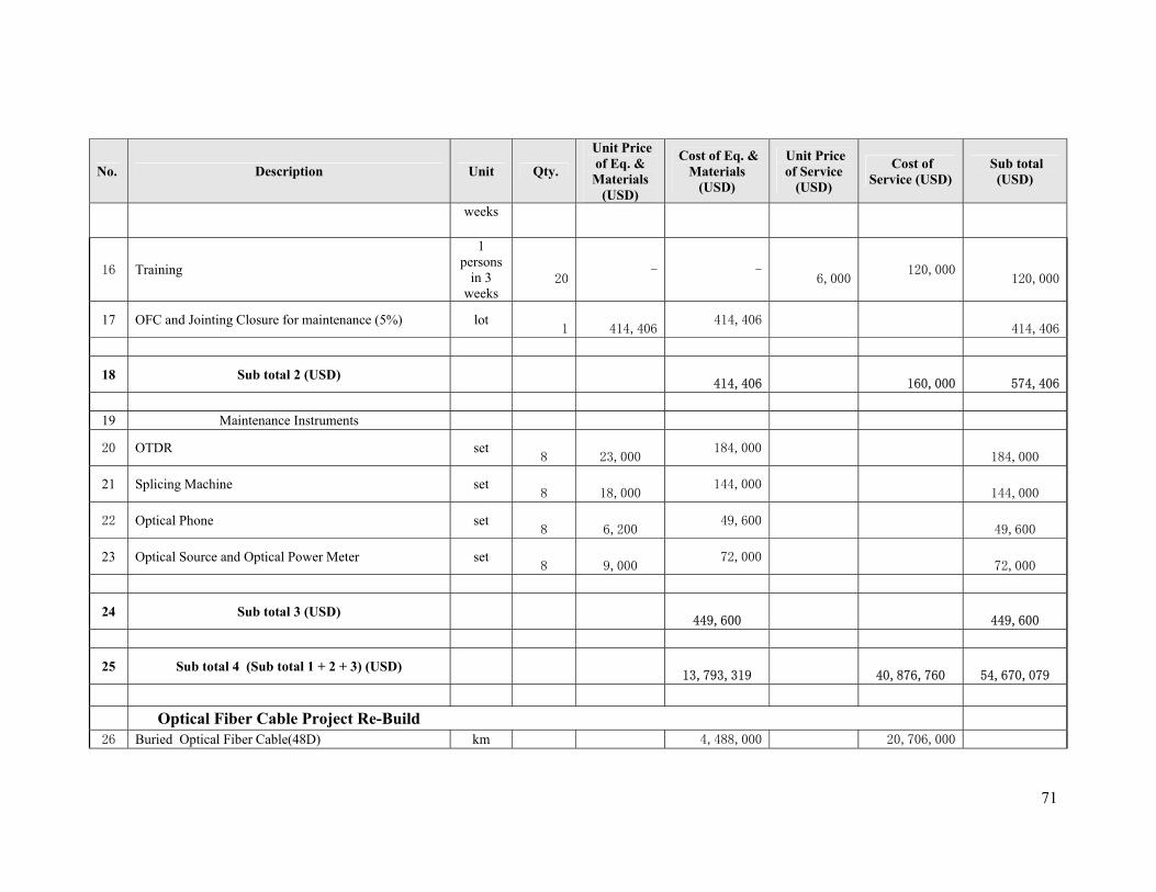
71
No. Description Unit Qty.
Unit Price of Eq. & Materials
(USD)
Cost of Eq. & Materials
(USD)
Unit Price of Service
(USD)
Cost of Service (USD)
Sub total (USD)
weeks
16 Training
1 persons
in 3 weeks
20 - -
6,000 120,000
120,000
17 OFC and Jointing Closure for maintenance (5%) lot
1
414,406 414,406
414,406
18 Sub total 2 (USD)
414,406
160,000 574,406
19 Maintenance Instruments
20 OTDR set
8
23,000 184,000
184,000
21 Splicing Machine set
8
18,000 144,000
144,000
22 Optical Phone set
8
6,200 49,600
49,600
23 Optical Source and Optical Power Meter set
8
9,000 72,000
72,000
24 Sub total 3 (USD)
449,600
449,600
25 Sub total 4 (Sub total 1 + 2 + 3) (USD)
13,793,319
40,876,760
54,670,079
Optical Fiber Cable Project Re-Build 26 Buried Optical Fiber Cable(48D) km 4,488,000 20,706,000
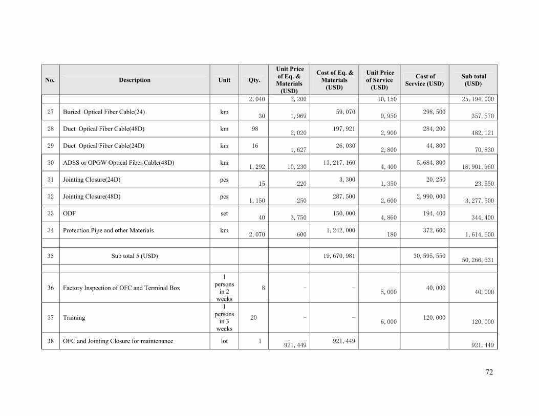
72
No. Description Unit Qty.
Unit Price of Eq. & Materials
(USD)
Cost of Eq. & Materials
(USD)
Unit Price of Service
(USD)
Cost of Service (USD)
Sub total (USD)
2,040 2,200 10,150 25,194,000
27 Buried Optical Fiber Cable(24) km
30
1,969 59,070
9,950 298,500
357,570
28 Duct Optical Fiber Cable(48D) km 98
2,020 197,921
2,900 284,200
482,121
29 Duct Optical Fiber Cable(24D) km 16
1,627 26,030
2,800 44,800
70,830
30 ADSS or OPGW Optical Fiber Cable(48D) km
1,292
10,230 13,217,160
4,400 5,684,800
18,901,960
31 Jointing Closure(24D) pcs
15
220 3,300
1,350 20,250
23,550
32 Jointing Closure(48D) pcs
1,150
250 287,500
2,600 2,990,000
3,277,500
33 ODF set
40
3,750 150,000
4,860 194,400
344,400
34 Protection Pipe and other Materials km
2,070
600 1,242,000
180 372,600
1,614,600
35 Sub total 5 (USD) 19,670,981 30,595,550 50,266,531
36 Factory Inspection of OFC and Terminal Box
1 persons
in 2 weeks
8 - -
5,000 40,000
40,000
37 Training
1 persons
in 3 weeks
20 - -
6,000 120,000
120,000
38 OFC and Jointing Closure for maintenance lot 1
921,449 921,449
921,449
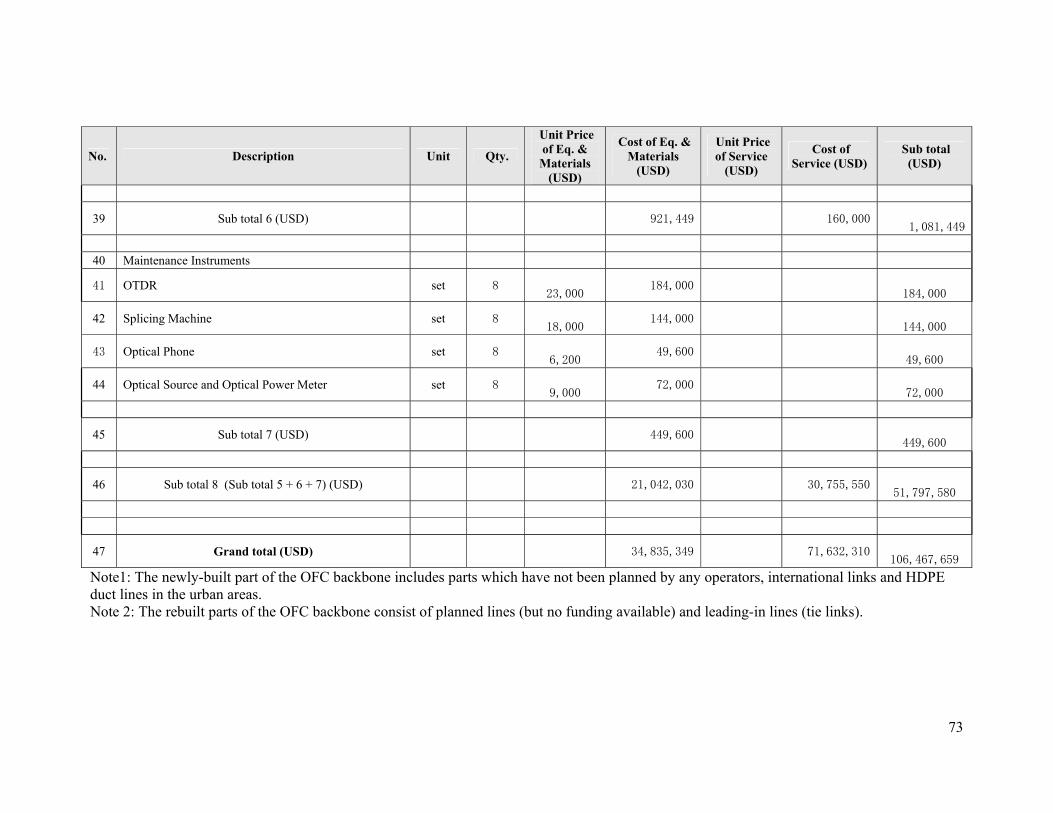
73
No. Description Unit Qty.
Unit Price of Eq. & Materials
(USD)
Cost of Eq. & Materials
(USD)
Unit Price of Service
(USD)
Cost of Service (USD)
Sub total (USD)
39 Sub total 6 (USD) 921,449 160,000 1,081,449
40 Maintenance Instruments
41 OTDR set 8
23,000 184,000
184,000
42 Splicing Machine set 8
18,000 144,000
144,000
43 Optical Phone set 8
6,200 49,600
49,600
44 Optical Source and Optical Power Meter set 8
9,000 72,000
72,000
45 Sub total 7 (USD) 449,600
449,600
46 Sub total 8 (Sub total 5 + 6 + 7) (USD) 21,042,030 30,755,550
51,797,580
47 Grand total (USD) 34,835,349 71,632,310
106,467,659
Note1: The newly-built part of the OFC backbone includes parts which have not been planned by any operators, international links and HDPE duct lines in the urban areas. Note 2: The rebuilt parts of the OFC backbone consist of planned lines (but no funding available) and leading-in lines (tie links).
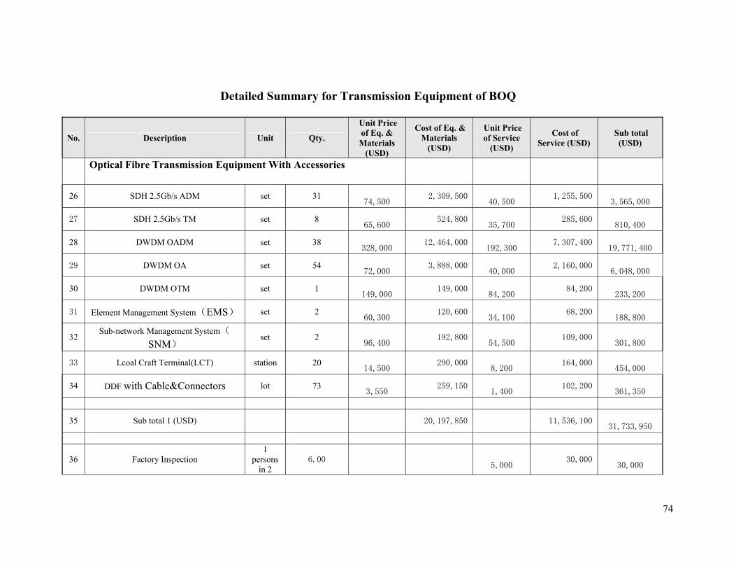
74
Detailed Summary for Transmission Equipment of BOQ
No. Description Unit Qty.
Unit Price of Eq. & Materials
(USD)
Cost of Eq. & Materials
(USD)
Unit Price of Service
(USD)
Cost of Service (USD)
Sub total (USD)
Optical Fibre Transmission Equipment With Accessories
26 SDH 2.5Gb/s ADM set 31
74,500 2,309,500
40,500 1,255,500
3,565,000
27 SDH 2.5Gb/s TM set 8
65,600 524,800
35,700 285,600
810,400
28 DWDM OADM set 38
328,000 12,464,000
192,300 7,307,400
19,771,400
29 DWDM OA set 54
72,000 3,888,000
40,000 2,160,000
6,048,000
30 DWDM OTM set 1
149,000 149,000
84,200 84,200
233,200
31 Element Management System(EMS) set 2
60,300 120,600
34,100 68,200
188,800
32 Sub-network Management System(
SNM) set 2
96,400 192,800
54,500 109,000
301,800
33 Lcoal Craft Terminal(LCT) station 20
14,500 290,000
8,200 164,000
454,000
34 DDF with Cable&Connectors lot 73
3,550 259,150
1,400 102,200
361,350
35 Sub total 1 (USD) 20,197,850 11,536,100
31,733,950
36 Factory Inspection 1
persons in 2
6.00
5,000 30,000
30,000
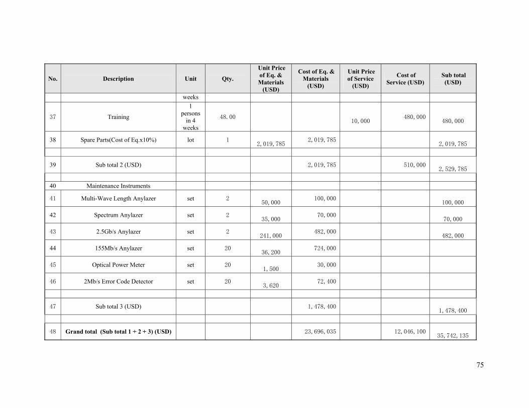
75
No. Description Unit Qty.
Unit Price of Eq. & Materials
(USD)
Cost of Eq. & Materials
(USD)
Unit Price of Service
(USD)
Cost of Service (USD)
Sub total (USD)
weeks
37 Training
1 persons
in 4 weeks
48.00
10,000 480,000
480,000
38 Spare Parts(Cost of Eq.x10%) lot 1
2,019,785 2,019,785
2,019,785
39 Sub total 2 (USD) 2,019,785 510,000
2,529,785
40 Maintenance Instruments
41 Multi-Wave Length Anylazer set 2
50,000 100,000
100,000
42 Spectrum Anylazer set 2
35,000 70,000
70,000
43 2.5Gb/s Anylazer set 2
241,000 482,000
482,000
44 155Mb/s Anylazer set 20
36,200 724,000
45 Optical Power Meter set 20
1,500 30,000
46 2Mb/s Error Code Detector set 20
3,620 72,400
47 Sub total 3 (USD) 1,478,400
1,478,400
48 Grand total (Sub total 1 + 2 + 3) (USD) 23,696,035 12,046,100
35,742,135
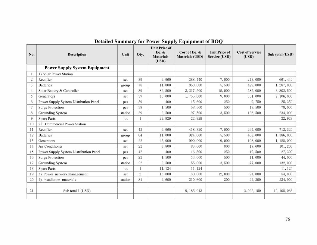
76
Detailed Summary for Power Supply Equipment of BOQ
No. Description Unit Qty.
Unit Price of Eq. &
Materials (USD)
Cost of Eq. & Materials (USD)
Unit Price of Service (USD)
Cost of Service (USD) Sub total (USD)
Power Supply System Equipment
1 1).Solar Power Station
2 Rectifier set 39 9,960 388,440 7,000 273,000 661,440
3 Batteries group 78 11,000 858,000 5,500 429,000 1,287,000
4 Solar Battery & Controller set 39 82,500 3,217,500 15,000 585,000 3,802,500
5 Generators set 39 45,000 1,755,000 9,000 351,000 2,106,000
6 Power Supply System Distrbution Panel pcs 39 400 15,600 250 9,750 25,350
7 Surge Protection pcs 39 1,500 58,500 500 19,500 78,000
8 Grounding System station 39 2,500 97,500 3,500 136,500 234,000
9 Spare Parts lot 1 22,929 22,929 22,929
10 2).Commercial Power Station
11 Rectifier set 42 9,960 418,320 7,000 294,000 712,320
12 Batteries group 84 11,000 924,000 5,500 462,000 1,386,000
13 Generators set 22 45,000 990,000 9,000 198,000 1,188,000
14 Air Conditioner set 22 3,800 83,600 800 17,600 101,200
15 Power Supply System Distribution Panel pcs 42 400 16,800 250 10,500 27,300
16 Surge Protection pcs 22 1,500 33,000 500 11,000 44,000
17 Grounding System station 22 2,500 55,000 3,500 77,000 132,000
18 Spare Parts lot 1 11,124 11,124 11,124
19 3). Power network management set 2 15,000 30,000 12,000 24,000 54,000
20 4). installation materials station 81 2,600 210,600 300 24,300 234,900
21 Sub total 1 (USD) 9,185,913 2,922,150 12,108,063
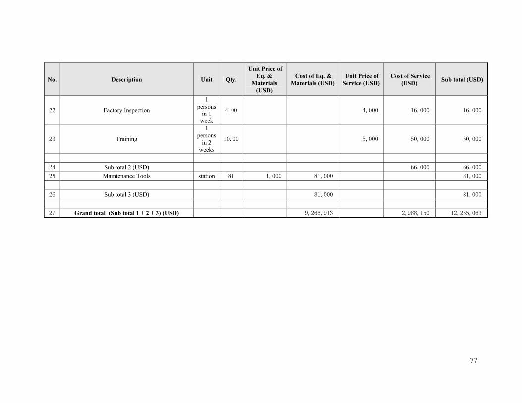
77
No. Description Unit Qty.
Unit Price of Eq. &
Materials (USD)
Cost of Eq. & Materials (USD)
Unit Price of Service (USD)
Cost of Service (USD) Sub total (USD)
22 Factory Inspection
1 persons
in 1 week
4.00 4,000 16,000 16,000
23 Training
1 persons
in 2 weeks
10.00 5,000 50,000 50,000
24 Sub total 2 (USD) 66,000 66,000
25 Maintenance Tools station 81 1,000 81,000 81,000
26 Sub total 3 (USD) 81,000 81,000
27 Grand total (Sub total 1 + 2 + 3) (USD) 9,266,913 2,988,150 12,255,063
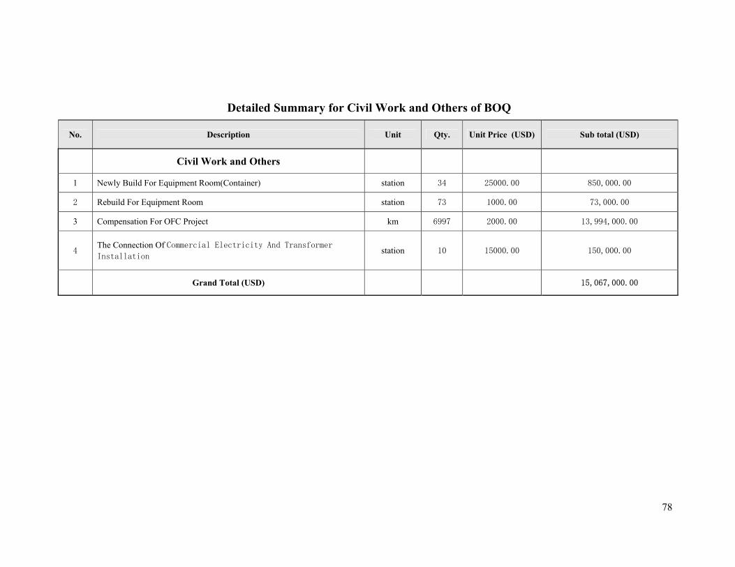
78
Detailed Summary for Civil Work and Others of BOQ
No. Description Unit Qty. Unit Price (USD) Sub total (USD)
Civil Work and Others
1 Newly Build For Equipment Room(Container) station 34 25000.00 850,000.00
2 Rebuild For Equipment Room station 73 1000.00 73,000.00
3 Compensation For OFC Project km 6997 2000.00 13,994,000.00
4 The Connection Of Commercial Electricity And Transformer Installation station 10 15000.00 150,000.00
Grand Total (USD) 15,067,000.00

79
Appendix C: Members of the Steering Committee 1. Salim H. Msoma MoCT Chairman 2. Eng. E. OleKambainei MoCT Moderator 3. Eng. A.B. Kowero MoCT Member 4. Ali A Mufuruki IRT/ WG Member 5. A. S. Mbeo TUT Member 6. Mohamed Mussa ZANTEL Member 7. Sunil Vedd SONGAS Member 8. Col. A. N. Nalingigwa MoDANS Member 9. Peter Ngota TTCL Member 10. Prof. J. S. Nkoma TCRA Member 11. Suhail Sherrif TISPA Member 12. Benhadard M. Tito TRC Member 13. Mr. L. A. Gewe TPC Member 13. Mr. O. Mzee UNDP Member 14. Pearson Lubumbe TAZARA Member 15. Dr. J. S. Kilongola (DICT) TCRA Member 16. M. Kamulika MoCT Member 17. Samson Mwela MoCT Member 19. Eng. J. Kilaba TCRA Member
20 Eng. M. A. Saleh TANESCO Member 21 Mr. F. Tabaro MOAT Member
Appendix D: Members of the Technical Working Group 1. Eng. E. N. Ole-Kambainei MoCT Co-ordinator 2. Eng. A.B. Kowero MoCT Chairman 3 Eng. J. Kilaba TCRA Member 4. Eng. M. S. Madulu TANESCO Co-opted Member 5. Eng. E. Nagunwa TTCL Member 6. Suhail Sherrif TISPA Member 7. Maj. Y.H. Mohamed MoDNS Co-opted Member 8. Mr. L. A. Gewe TPC Co-opted Member 9. Eng. C. Nkwabi TAZARA Member 10. Mr. M. Kamulika MoCT Secretariat 11. Eng. E. Obeid TANESCO Co-opted Member 12. Eng. A. S. Mbeo TUT Member 13. Eng. L. Hemela TTCL Co-opted Member 14. Mr. Li Hui CITCC Member 15. Mr. Gao Xingping CITCC Member 16. Qu xin CITCC Member 17. Yin wei Xing CITCC Member 18. Ye jianjun CITCC Member 19. Tang XiaoHao CITCC Member 20. Shen Wangping CITCC Member

80
Appendix E: Members of Survey Teams
Northern Group:
1. Maj. Y. Mohamed MoDANS Group Leader (local) 2. Eng. Emmanuel Nagunwa TTCL Member 3. Eng. Obedi Elirehema TANESCO Member 4. Shen Wangping CITCC Member 5. Mr. Li Hui CITCC Member 6. Mr. Gao Xingping CITCC Group Leader (CITCC)
Southern Group:
1. Shija Madulu TANESCO Group Leader (local) 2. Eng. Leonard Hemela TTCL Member 3. Eng. C. Nkwabi TAZARA Member 4. Ye jianjun CITCC Group Leader (CITCC) 5. Qu xin CITCC Member
Appendix F: Members of the Report Drafting Group 1. Eng. Emmanuel Nagunwa TTCL Coordinator 2. Eng. James M. Kilaba TCRA Member 3. Eng. Elirehema Obedi TANESCO Member 4. Mr. Masegese Kamulika MoCT Secretariat 5. Ye jianjun CITCC Member 6. Qu xin CITCC Member 7. Mr. Gao Xingping CITCC Member 8. Mr. Li Hui CITCC Member 9. Shen Wangping CITCC Interpreter

81
Appendix G: Report on Status of the National ICT Backbone Infrastructure