Embed Size (px)
Citation preview
Related LabView programs*:
1. For a single curve acquisition, FET Sample 4W.VI
C:\LabView Programs\Bruevv\FET Sample 4W.VI
2. For acquisition of a series of curves, FET Series 4W.VI
C:\LabView Programs\Bruevv\FET Series 4W.VI
*programs are also available in the "cloud" following this link (all content to be copied to local drive):
https://1drv.ms/u/s!Aq-yhUhXNVPbo7I-RbDnSD0EZsPBug?e=pZERfE
Technical notes on wiring FETs to measuring circuit
and data collection with LabView programs
(can be used either for four-probe or two-probe FETs)
10/10/2019 V. Bruevich (Podzorov group, Rutgers U.) 1
10/10/2019 V. Bruevich (Podzorov group, Rutgers U.) 2
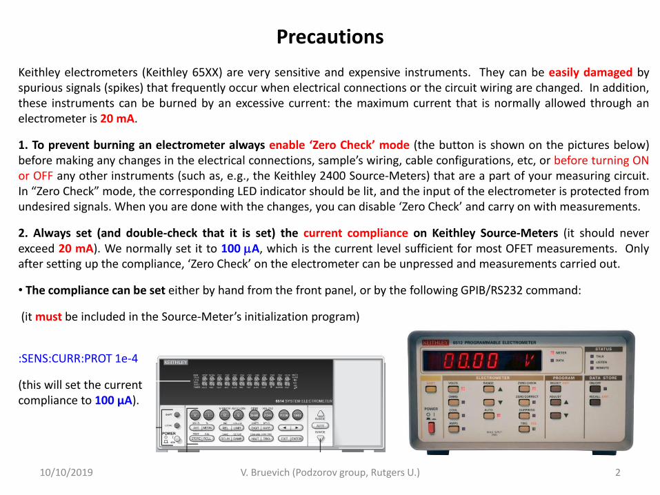
Keithley electrometers (Keithley 65XX) are very sensitive and expensive instruments. They can be easily damaged by spurious signals (spikes) that frequently occur when electrical connections or the circuit wiring are changed. In addition, these instruments can be burned by an excessive current: the maximum current that is normally allowed through an electrometer is 20 mA.
1. To prevent burning an electrometer always enable ‘Zero Check’ mode (the button is shown on the pictures below) before making any changes in the electrical connections, sample’s wiring, cable configurations, etc, or before turning ON or OFF any other instruments (such as, e.g., the Keithley 2400 Source-Meters) that are a part of your measuring circuit. In “Zero Check” mode, the corresponding LED indicator should be lit, and the input of the electrometer is protected from undesired signals. When you are done with the changes, you can disable ‘Zero Check’ and carry on with measurements.
2. Always set (and double-check that it is set) the current compliance on Keithley Source-Meters (it should never exceed 20 mA). We normally set it to 100 A, which is the current level sufficient for most OFET measurements. Only after setting up the compliance, ‘Zero Check’ on the electrometer can be unpressed and measurements carried out.
• The compliance can be set either by hand from the front panel, or by the following GPIB/RS232 command:
(it must be included in the Source-Meter’s initialization program)
:SENS:CURR:PROT 1e-4
(this will set the current compliance to 100 µA).
Precautions
10/10/2019 V. Bruevich (Podzorov group, Rutgers U.) 3
Some comments on device/contacts fabrication Preparing contacts to your sample.
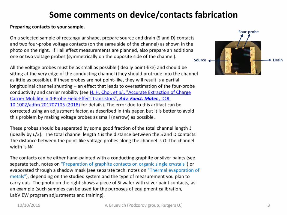
On a selected sample of rectangular shape, prepare source and drain (S and D) contacts and two four-probe voltage contacts (on the same side of the channel) as shown in the photo on the right. If Hall effect measurements are planned, also prepare an additional one or two voltage probes (symmetrically on the opposite side of the channel).
All the voltage probes must be as small as possible (ideally point-like) and should be sitting at the very edge of the conducting channel (they should protrude into the channel as little as possible). If these probes are not point-like, they will result is a partial longitudinal channel shunting – an effect that leads to overestimation of the four-probe conductivity and carrier mobility (see H. H. Choi, et al., "Accurate Extraction of Charge Carrier Mobility in 4-Probe Field-Effect Transistors", Adv. Funct. Mater., DOI: 10.1002/adfm.201707105 (2018) for details). The error due to this artifact can be corrected using an adjustment factor, as described in this paper, but it is better to avoid this problem by making voltage probes as small (narrow) as possible.
These probes should be separated by some good fraction of the total channel length L (ideally by L/3). The total channel length L is the distance between the S and D contacts. The distance between the point-like voltage probes along the channel is D. The channel width is W.
The contacts can be either hand-painted with a conducting graphite or silver paints (see separate tech. notes on "Preparation of graphite contacts on organic single crystals") or evaporated through a shadow mask (see separate tech. notes on "Thermal evaporation of metals"), depending on the studied system and the type of measurement you plan to carry out. The photo on the right shows a piece of Si wafer with silver paint contacts, as an example (such samples can be used for the purposes of equipment calibration, LabVIEW program adjustments and training).
Wiring a device in the measurement box
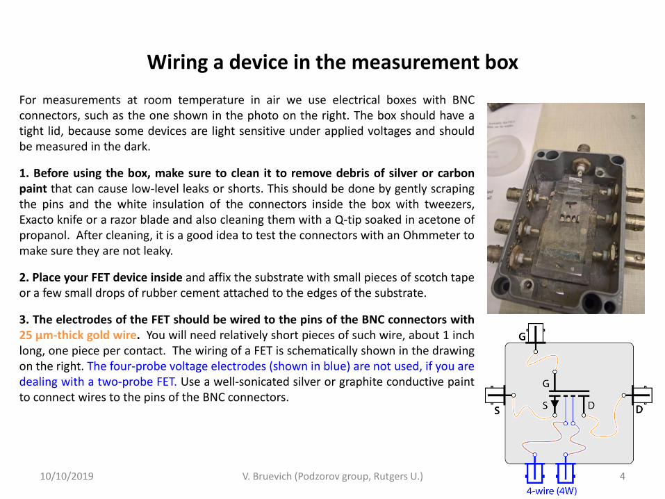
For measurements at room temperature in air we use electrical boxes with BNC connectors, such as the one shown in the photo on the right. The box should have a tight lid, because some devices are light sensitive under applied voltages and should be measured in the dark.
1. Before using the box, make sure to clean it to remove debris of silver or carbon paint that can cause low-level leaks or shorts. This should be done by gently scraping the pins and the white insulation of the connectors inside the box with tweezers, Exacto knife or a razor blade and also cleaning them with a Q-tip soaked in acetone of propanol. After cleaning, it is a good idea to test the connectors with an Ohmmeter to make sure they are not leaky.
2. Place your FET device inside and affix the substrate with small pieces of scotch tape or a few small drops of rubber cement attached to the edges of the substrate.
3. The electrodes of the FET should be wired to the pins of the BNC connectors with 25 µm-thick gold wire. You will need relatively short pieces of such wire, about 1 inch long, one piece per contact. The wiring of a FET is schematically shown in the drawing on the right. The four-probe voltage electrodes (shown in blue) are not used, if you are dealing with a two-probe FET. Use a well-sonicated silver or graphite conductive paint to connect wires to the pins of the BNC connectors.
10/10/2019 V. Bruevich (Podzorov group, Rutgers U.) 4
Electrometer’s TRIAX connections
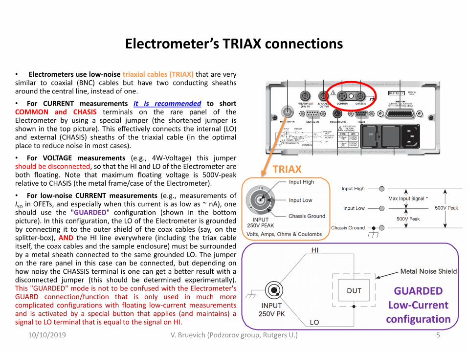
• Electrometers use low-noise triaxial cables (TRIAX) that are very similar to coaxial (BNC) cables but have two conducting sheaths around the central line, instead of one.
• For CURRENT measurements it is recommended to short COMMON and CHASIS terminals on the rare panel of the Electrometer by using a special jumper (the shortened jumper is shown in the top picture). This effectively connects the internal (LO) and external (CHASIS) sheaths of the triaxial cable (in the optimal place to reduce noise in most cases).
• For VOLTAGE measurements (e.g., 4W-Voltage) this jumper should be disconnected, so that the HI and LO of the Electrometer are both floating. Note that maximum floating voltage is 500V-peak relative to CHASIS (the metal frame/case of the Electrometer).
• For low-noise CURRENT measurements (e.g., measurements of ISD in OFETs, and especially when this current is as low as ~ nA), one should use the "GUARDED" configuration (shown in the bottom picture). In this configuration, the LO of the Electrometer is grounded by connecting it to the outer shield of the coax cables (say, on the splitter-box), AND the HI line everywhere (including the triax cable itself, the coax cables and the sample enclosure) must be surrounded by a metal sheath connected to the same grounded LO. The jumper on the rare panel in this case can be connected, but depending on how noisy the CHASSIS terminal is one can get a better result with a disconnected jumper (this should be determined experimentally). This "GUARDED" mode is not to be confused with the Electrometer's GUARD connection/function that is only used in much more complicated configurations with floating low-current measurements and is activated by a special button that applies (and maintains) a signal to LO terminal that is equal to the signal on HI.
10/10/2019 V. Bruevich (Podzorov group, Rutgers U.) 5
GUARDED Low-Current configuration
TRIAX
10/10/2019 V. Bruevich (Podzorov group, Rutgers U.) 6
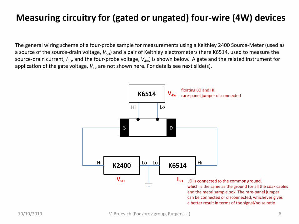
Measuring circuitry for (gated or ungated) four-wire (4W) devices
The general wiring scheme of a four-probe sample for measurements using a Keithley 2400 Source-Meter (used as a source of the source-drain voltage, VSD) and a pair of Keithley electrometers (here K6514, used to measure the source-drain current, ISD, and the four-probe voltage, V4w) is shown below. A gate and the related instrument for application of the gate voltage, VG, are not shown here. For details see next slide(s).
floating LO and HI, rare-panel jumper disconnected
LO is connected to the common ground, which is the same as the ground for all the coax cables and the metal sample box. The rare-panel jumper can be connected or disconnected, whichever gives a better result in terms of the signal/noise ratio.
10/10/2019 V. Bruevich (Podzorov group, Rutgers U.) 7
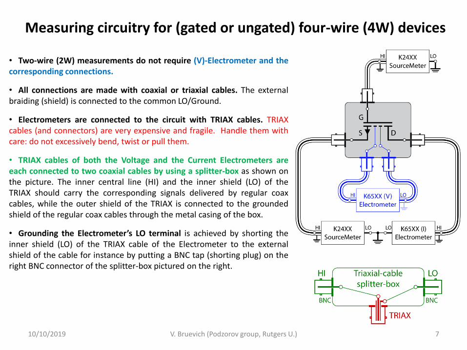
Measuring circuitry for (gated or ungated) four-wire (4W) devices
• Two-wire (2W) measurements do not require (V)-Electrometer and the corresponding connections.
• All connections are made with coaxial or triaxial cables. The external braiding (shield) is connected to the common LO/Ground.
• Electrometers are connected to the circuit with TRIAX cables. TRIAX cables (and connectors) are very expensive and fragile. Handle them with care: do not excessively bend, twist or pull them.
• TRIAX cables of both the Voltage and the Current Electrometers are each connected to two coaxial cables by using a splitter-box as shown on the picture. The inner central line (HI) and the inner shield (LO) of the TRIAX should carry the corresponding signals delivered by regular coax cables, while the outer shield of the TRIAX is connected to the grounded shield of the regular coax cables through the metal casing of the box.
• Grounding the Electrometer’s LO terminal is achieved by shorting the inner shield (LO) of the TRIAX cable of the Electrometer to the external shield of the cable for instance by putting a BNC tap (shorting plug) on the right BNC connector of the splitter-box pictured on the right.
10/10/2019 V. Bruevich (Podzorov group, Rutgers U.) 8
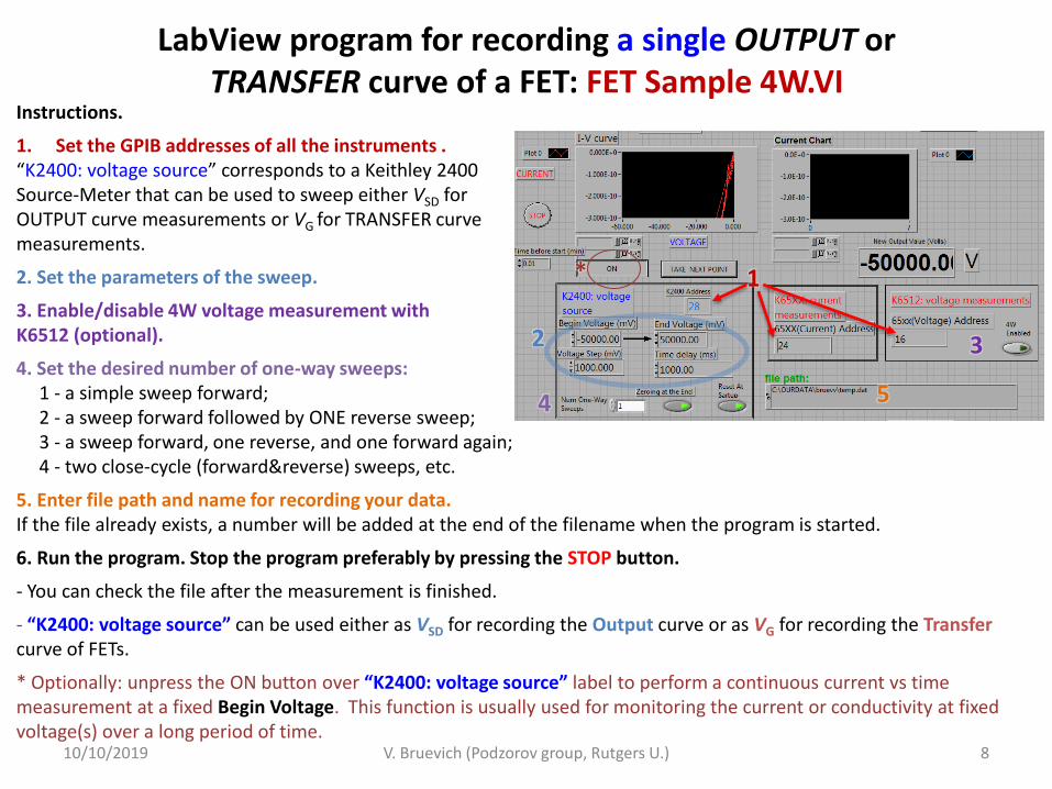
LabView program for recording a single OUTPUT or TRANSFER curve of a FET: FET Sample 4W.VI
Instructions.
1. Set the GPIB addresses of all the instruments . “K2400: voltage source” corresponds to a Keithley 2400 Source-Meter that can be used to sweep either VSD for OUTPUT curve measurements or VG for TRANSFER curve measurements.
2. Set the parameters of the sweep.
3. Enable/disable 4W voltage measurement with K6512 (optional).
4. Set the desired number of one-way sweeps: 1 - a simple sweep forward; 2 - a sweep forward followed by ONE reverse sweep; 3 - a sweep forward, one reverse, and one forward again; 4 - two close-cycle (forward&reverse) sweeps, etc.
5. Enter file path and name for recording your data. If the file already exists, a number will be added at the end of the filename when the program is started.
6. Run the program. Stop the program preferably by pressing the STOP button.
- You can check the file after the measurement is finished.
- “K2400: voltage source” can be used either as VSD for recording the Output curve or as VG for recording the Transfer curve of FETs.
* Optionally: unpress the ON button over “K2400: voltage source” label to perform a continuous current vs time measurement at a fixed Begin Voltage. This function is usually used for monitoring the current or conductivity at fixed voltage(s) over a long period of time.
1
2
*
3
4 5
10/10/2019 V. Bruevich (Podzorov group, Rutgers U.) 9
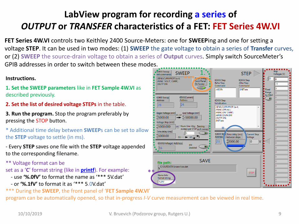
Instructions.
1. Set the SWEEP parameters like in FET Sample 4W.VI as described previously.
2. Set the list of desired voltage STEPs in the table.
3. Run the program. Stop the program preferably by pressing the STOP button.
* Additional time delay between SWEEPs can be set to allow the STEP voltage to settle (in ms).
- Every STEP saves one file with the STEP voltage appended to the corresponding filename.
** Voltage format can be set as a ‘C’ format string (like in printf). For example: - use ‘%.0fV’ to format the name as ‘*** 5V.dat’ - or ‘%.1fV’ to format it as ‘*** 5.0V.dat’ *** During the SWEEP, the front panel of ‘FET Sample 4W.VI’ program can be automatically opened, so that in-progress I-V curve measurement can be viewed in real time.
LabView program for recording a series of OUTPUT or TRANSFER characteristics of a FET: FET Series 4W.VI
FET Series 4W.VI controls two Keithley 2400 Source-Meters: one for SWEEPing and one for setting a voltage STEP. It can be used in two modes: (1) SWEEP the gate voltage to obtain a series of Transfer curves, or (2) SWEEP the source-drain voltage to obtain a series of Output curves. Simply switch SourceMeter’s GPIB addresses in order to switch between these modes.
*
1.
**
***