Embed Size (px)
Citation preview

NASA Technical Memorandum 86264
A ROUTE GENERATOR CONCEPT FOR AIRCRAFT
ONBOARD FAULT MONITORING
MICHAEL T. PALMER
KATHY H. ABBOTT
AUGUST 1984
National Aeronautics and Space Administration
Langley Research Center Hampton, Virginia 23665

SUMMARY
Because o f t h e i n c r e a s i n g l y complex environments i n which t h e f l i g h t crews of commercial a v i a t i o n a i r c r a f t must operate, a research e f f o r t i s c u r r e n t l y underway a t NASA Langley Research Center t o i n v e s t i gate t h e p o t e n t i a1 b e n e f i t s o f i n t e l l i g e n t cockp i t aids, and t o es tab l i sh gu ide l ines f o r t h e a p p l i c a t i o n o f a r t i f i c i a1 i n t e l 1 i gence techniques t o advanced f 1 i ght management concepts. The segment o f t h i s research area t h a t concentrates on automated f a u l t m o n i t o r i n g and diagnosis requi res t h a t a re ference frame e x i s t , against which t h e cur ren t s t a t e o f t h e a i r c r a f t may be compared t o determine t h e ex is tence of a f a u l t . Th is paper describes a computer program which generates t h e p o r t i o n o f t h a t reference frame that s p e c i f i e s t h e h o r i z o n t a l f l i g h t route.
INTRODUCTION
I n t h e commercial a v i a t i o n indust ry , safety and e f f i c i e n c y are o f utmost importance. F l i g h t crews must operate i n i n c r e a s i n g l y complex environments, and automation i n t h e form o f i n t e l l i g e n t cockp i t a ids may a s s i s t them i n i mprovi ng sa fe ty and e f f i c i e n c y Modern microprocessor and d i sp lay technol ogy have made it f e a s i b l e t o automate many f l i g h t deck funct ions, and t h e advent of expert systems technol ogy has proven t h a t a r t i f i c i a1 i n t e l 1 i gence ( A I ) has a great deal t o o f fe r t o enhance and aid t h e man i n t h e system. I n p a r t i c u l a r , automation o f f a u l t monitor ing and diagnosis i s des i rab le t o ensure sa fe and e f f i c i e n t operat ions, since response t o f a u l t s on board an a i r c r a f t i s o f t e n t ime c r i t i c a l . It i s be l ieved t h a t t h e use o f a r t i f i c i a l i n t e l l i g e n c e concepts can f a c i l i t a t e t h i s automation.
An e f f o r t i s c u r r e n t l y underway a t NASA Langley Research Center t o i n v e s t i g a t e t i re p o t e n t i a l b e n e f i t s o f i n t e l l i g e n t cockpi t a ids, and t o e s t a b i i s h guide1 i nes f o r t h e appl i c a t i on o f A I techniques t o advanced f l i ght management concepts. One a p p l i c a t i o n area w i t h i n t h i s research e f f o r t i s onboard f a u l t mon i to r ing and diagnosis. automated f a u l t mon i to r ing requi res that t h e ac tua l a i r c r a f t s t a t e be compared t o some des i red reference a i r c r a f t s ta te i n order t o de tec t t h e ex is tence of a f a u l t .
The segment o f t h i s area t h a t concentrates on
The a i r c r a f t s t a t e has been d iv ided i n t o p o r t i o n s t o f a c i l i t a t e t h e generat ion of t h e des i red reference a i r c r a f t s t a t e . A computer program has been developed t o generate t h e p o r t i o n o f t h i s reference s t a t e t h a t s p e c i f i e s a h o r i z o n t a l r o u t e m i n i m i z i ng ground d i stance between t h e o r i g i n and d e s t i n a t i on a i r p o r t s us ing t h e establ i shed a i rway system designated by t h e Federal
documents t h i s computer program and describes i t s use and capabi 1 i t i e s . . A v i a t i o n Admin is t ra t ion and i n use by Air T r a f f i c Contro l . Th is r e p o r t
BACKGROUND
The i n i t i a l concepts f o r t h e f a u l t moni tor ing and d iagnosis segment of t h e i n t e l 1 i gent f 1 i ght management research were devel oped a t t h e Uni v e r s i ty of
I 1 1 i noi s a t Urbana-Champai gn under a grant from NASA Langley Research Center ( r e f . 1). The major t h r u s t of t h e work was t o exp lo re the e x i s t i n g a r t i f i c i a l i n t e l 1 i gence techniques appl i cab le t o f a u l t mon i to r ing and d iagnosis w i t h i n t h e f l i g h t domain and, i f necessary, develop new techniques more s u i t e d t o t h i s app l i ca t ion . Out of t h i s research came t h e bas ic concepts f o r a m l t i - l e v e l a rch i tec tu re w i t h i n which t h e f a u l t mon i to r i ng segment would operate. The d e s c r i p t i o n and prec ise f u n c t i o n of each of t he l e v e l s w i t h i n t h i s a r c h i t e c t u r e have evolved as new ideas were incorporated.
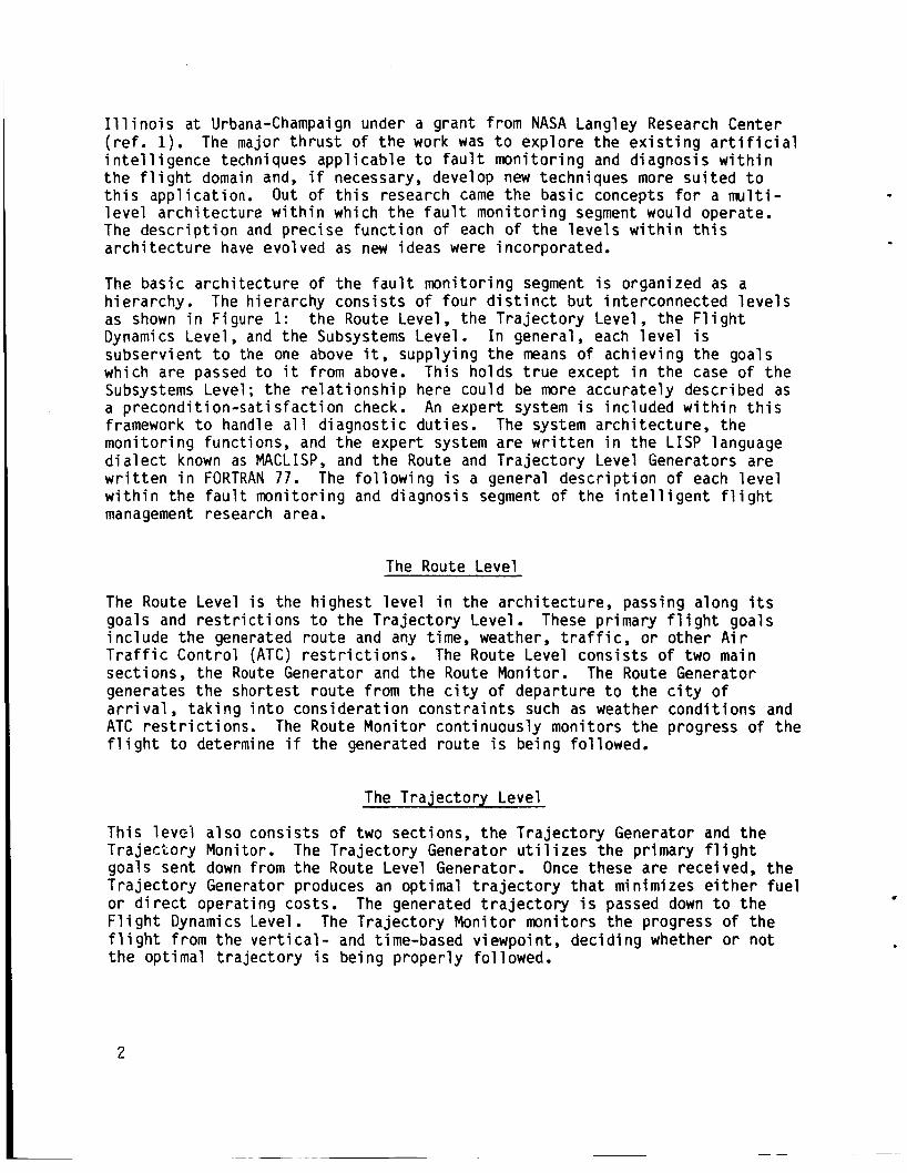
The bas ic a rch i tec tu re o f t he f a u l t mon i to r ing segment i s organized as a h ie ra rchy . The h ie rarchy cons is ts o f f o u r d i s t i n c t bu t in terconnected l e v e l s as shown i n Figure 1: t h e Route Level, t he T ra jec to ry Level, t h e F l i g h t Dynamics Level , and the Subsystems Level . I n general, each l e v e l i s subserv ient t o the one above it, supply ing t h e means o f achiev ing the goals which are passed t o i t from above. This ho lds t r u e except i n the case o f t h e Subsystems Level; t h e r e l a t i o n s h i p here could be more accura te ly descr ibed as a p recond i t i on -sa t i s fac t i on check. An exper t system i s inc luded w i t h i n t h i s framework t o handle a l l d iagnos t ic dut ies. The system a rch i tec tu re , t he mon i to r i ng funct ions, and the exper t system are w r i t t e n i n t h e LISP language d i a l e c t known as MACLISP, and t h e Route and T ra jec to ry Level Generators a re w r i t t e n i n FORTRAN 77. The f o l l o w i n g i s a general d e s c r i p t i o n o f each l e v e l w i t h i n t h e f a u l t mon i to r ing and diagnosis segment o f the i n t e l l i g e n t f l i g h t management research area.
The Route Level
The Route Level i s the h ighest l e v e l i n the a rch i tec tu re , passing along i t s goals and r e s t r i c t i o n s t o t h e T ra jec to ry Level These pr imary f l i g h t goals i n c l u d e t h e generated rou te and any time, weather, t r a f f i c , o r o ther A i r T r a f f i c Cont ro l (ATC) r e s t r i c t i o n s . The Route Level cons i s t s of two main sect ions, t he Route Generator and the Route Monitor. The Route Generator generates t h e shor test rou te f rom t h e c i t y o f depar ture t o the c i t y o f a r r i v a l , t a k i n g i n t o cons idera t ion cons t ra in t s such as weather cond i t i ons and ATC r e s t r i c t i o n s . f l i g h t t o determine i f t h e generated rou te i s being fol lowed.
The Route Moni tor cont inuously moni tors t h e progress o f t h e
The T ra jec to ry Level
This l e v e l a l so cons is ts o f two sect ions, t h e T ra jec to ry Generator and t h e T r a j e c t o r y Monitor. goals sent down from t h e Route Level Generator. Once these are received, t h e T r a j e c t o r y Generator produces an opt imal t r a j e c t o r y t h a t minimizes e i t h e r f u e l o r d i r e c t operat ing costs. F l i g h t Dynamics Level. The T ra jec to ry Moni tor moni tors the progress of t he f l i g h t f rom t h e v e r t i c a l - and time-based viewpoint , dec id ing whether o r no t t h e opt imal t r a j e c t o r y i s being proper ly fo l lowed.
The T ra jec to ry Generator u t i 1 i zes the pr imary fl i ght
The generated t r a j e c t o r y i s passed down t o t h e
2
The F l i g h t Dynamics Level
Th is l e v e l uses an i n t e r n a l model of the a i r c r a f t t o generate a l l necessary c o n t r o l i n p u t s such as wheel and column pos i t ions , t h r o t t l e p o s i t i o n s , and f l a p s e t t i n g s t h a t are requ i red t o achieve t h e des i red t r a j e c t o r y . sequence o f c o n t r o l i n p u t s i s then t r a n s f e r r e d down t o t h e Subsystems Level .
Th is
The Subsystems Level
The Subsystems Level checks t h e c o n t r o l i n p u t sequence and ampli tude t o assure t h a t t h e i n p u t s do not attempt t o extend t h e a i r c r a f t beyond i t s normal opera t iona l and performance l i m i t s . This l e v e l conta ins t h e knowledge about t h e a i r c r a f t subsystems, and checks t h a t each subsystem i s working proper ly .
When t h e checks a t t h e Subsystem Level have been completed, t h e F l i g h t Dynamics Level passes i t s sequence o f cont ro l inpu ts back up i n t o t h e T r a j e c t o r y Level, which then passes t h e generated optimum t r a j e c t o r y back up t o t h e Route Level. funct ions. Once t h e f l i g h t has been i n i t i a t e d , constant s u r v e i l l a n c e o f a l l c r i t i c a l parameters i s maintained, and i f any c o n d i t i o n i s observed t h a t has caused o r w i l l cause d e v i a t i o n from t h e planned route, t h e expert system i s ac t i va ted . The exper t system i t s e l f c u r r e n t l y uses a rule-based approach t o problem s o l v i n g as descr ibed i n r e f . 2, but t h i s w i l l l a t e r be expanded t o more c l o s e l y combine t h e func t ions o f e r r o r d e t e c t i o n and f a u l t d iagnosis i n t o a more u n i f i e d e f f o r t .
Here i t i s s to red f o r re fe renc ing by t h e r o u t e mon i to r ing
DESCRIPTION OF THE ROUTE GENERATOR
The Dn,,+- Cl l l r r r - ,+ r r 4 - . 4 r r 4 - r A ~ L - -..- L - - - -L .Cl.-L& -- & L a & 1 1 S B S G I\YUUG UCIIFI U~.UI 13 uea I Y I I C U I,U I U I I pi IUI t,u caul I i i ~ I I L 3u t,iiaL 5 I I c u r r e n t i n f o r m a t i o n on weather, t r a f f i c , and A i r T r a f f i c Contro l (ATC) i n s t r u c t i o n s can be used. are changed dur ing t h e f l i g h t so as t o render t h e p r e v i o u s l y generated r o u t e unacceptable, t h e Route Generator can be executed again us ing t h e next waypoint o f the path as t h e p o i n t o f departure, and t h e d e s t i n a t i o n a i r p o r t , whether d i f f e r e n t o r t h e same as o r i g i n a l l y planned, as t h e p o i n t o f a r r i Val . This i n f l i ght r e - r o u t i ng capabi 1 i t y i s t h e p r i n c i p a l advantage o f a program which a c t i v e l y generates t h e route r a t h e r than r e t r i e v i n g a r i g i d , preplanned course from a storage device. The Route Generator i t s e l f i s comprised o f two major sect ions, t h e Selector and t h e Compiler.
I f any o f these i n i t i a l c o n d i t i o n s o r i n s t r u c t i o n s
The Route Selector - The Route Se lec tor i s t h e sec t ion which chooses t h e s h o r t e s t a l lowable p a t h
System. w i t h i n t h i s program i n graph form, t h e nodes represent ing geographical re ference points , o r waypoints, and t h e arcs between these nodes denot ing t h e airway segments. Each arc must be assigned a we igh t ing f a c t o r . For t h e case
. from o r i g i n t o d e s t i n a t i o n us ing t h e establ ished High A l t i t u d e J e t Route For t h e purposes of analys is , the Je t Route System i s represented
3

of l o c a t i n g the shor tes t path between any two nodes i n t h e graph, t h i s wei g h t i ng fac to r i s represented by t h e m i leage between waypoi n ts . con ta in ing t h e d is tance in fo rmat ion i s arranged so t h a t arcs are i d e n t i f i e d by t h e i r 1 o c a t i on w i t h i n the two-di mensi onal graph. The i ndex f o r each d i mensi on i s a p o i n t e r t o t h e name of t h e corresponding node (waypoint) i n t h e one- dimensional mat r ix con ta in ing the node i d e n t i f i e r s . Thus the graph, when p r i n t e d out, takes the form o f a mileage char t , w i t h on ly those mileages shown t h a t represent e x i s t i n g segments. A sample p o r t i o n o f t he graph i s shown i n f i g u r e 2. o f arcs from o r i g i n t o d e s t i n a t i o n nodes uses D i j k s t r a ' s a lgo r i t hm ( r e f . 3 ) . This a lgo r i t hm loca tes the path of l e a s t res is tance through an ar ray o f we igh t ing factors , and i s i d e a l l y s u i t e d f o r a p p l i c a t i o n t o t h i s p a r t i c u l a r c l ass o f problem.
The m a t r i x
The subrout ine which performs the actual s e l e c t i o n o f t ne sequence
The Route Compiler
The Route Compiler assembles the sequence o f t r a c k angles (no-wind t r u e headings) and the corresponding d is tances requi red t o f o l l o w the chosen path through t h e es tab l i shed system o f j e t airways, as w e l l as t h e magnetic v a r i a t i o n from t r u e no r th associated w i t h each waypoint i n the path. Th is sequence contains t h e rou te i n fo rma t ion needed by t h e T ra jec to ry Level f o r generat ion o f the optimum t r a j e c t o r y , s ince i t descr ibes the actual t r a c k o f t h e a i r c r a f t across t h e ground.
CONSTRUCTION OF DATA BASES
There are f o u r data bases access ib le by t h e Route Generator. base i s contained i n the ma t r i x c a l l e d NAME, which holds t h e names o f a l l t h e waypoints s tored i n a lphabe t i ca l order. The p o s i t i o n o f each waypoint name w i t h i n t h i s array i s very important, because the remaining data bases use t h i s pos i t i on as a poi n t e r f o r i d e n t i f y i ng segments between waypoi n t s w i t h i n t h e c o n n e c t i v i t y matr ix. conta ins a l l the i n fo rma t ion necessary t o permi t t h e Se lec tor t o choose t h e sho r tes t rou te through t h e airway system from o r i g i n t o des t i na t i on . Th is inc ludes t h e endpoints o f each segment, t he segment length, and t h e d i r e c t i o n s o f t r a v e l permiss ib le on each segment. The t h i r d data base conta ins the t r a c k i n fo rma t ion necessary f o r t h e Compiler t o assemble the e n t i r e sequence o f t r a c k angles and mileages f o r passage down t o the T ra jec to ry Level. The f o u r t h data base conta ins the magnetic v a r i a t i o n f rom t r u e no r th associated w i t h each waypoint.
The f i r s t da ta
The second data base, c a l l e d t h e pr imary data base,
Each e n t r y i n the pr imary data base l i s t s general i n fo rma t ion on one p a r t i c u l a r a i may segment. numbers, and has the f o l l o w i n g format:
The en t r y i s cons t ruc ted e n t i r e l y o f i n t e g e r
AAABBB CCC DDD E
4

where
.
AAA i s a p o i n t e r t o t h e l o c a t i o n o f the name o f t h e f i r s t endpoint i n t h e NAME array,
BBB i s a p o i n t e r t o t h e loca t ion of t h e name of t h e second endpoint i n t h e NAME array,
CCC i s t h e J e t Route designat ion number,
DDD i s t h e length, i n n a u t i c a l miles, o f t h a t e n t i r e segment, and
E i s a d i r e c t i o n c o n s t r a i n t f l a g i n d i c a t i n g t h e a l lowable d i r e c t i o n s o f t r a v e l on t h a t segment:
0 - open ( t r a v e l i n both d i r e c t i o n s permiss ib le )
1 - t r a v e l inbound t o f i r s t endpoint on ly
2 - t r a v e l inbound t o second endpoint on ly
For example, n o t i c e i n f i g u r e 3 t h a t F o r t Lauderdale DME i s named FLL. In t h i s implementation FLL i s loca ted i n the NAME array in p o s i t i o n 21. Orlando VORTAC i s named ORL, and i s l oca ted i n t h e NAME array i n p o s i t i o n 48. The segment connect ing these two waypoints i s designated 320, and has an o v e r a l l leng th o f 161 n a u t i c a l mi les. Therefore, t h i s segment i s s to red i n t h e pr imary data base as:
021048 020 161 0
r L a b - - z i z - - nInc t.1 a i I i i iy LCI u i s the d i i - e ~ t f ~ i i coiisti-sint f l a g , i i i d i c a t i i i g t ha t t h i s segment i s normal ly open t o t r a v e l i n both d i r e c t i o n s .
Each e n t r y i n t h e t h i r d data base a lso l i s t s in fo rmat ion on only one airway segment, and i s const ructed o f only in teger numbers, bu t here it has t h e f o l 1 owi ng format :
AAABBB FF GGGHHH I I IJJJ KKKLLL . . etc. where
AAA i s a p o i n t e r t o t h e l o c a t i o n o f the name o f t h e f i r s t endpoint i n t h e NAME array,
BBB i s a p o i n t e r t o t h e l o c a t i o n o f t h e name o f t h e second endpoint i n t h e NAME array,
FF i s t h e number o f d i f f e r e n t p o r t i o n s compris ing t h e airway segment,
GGG i s t h e t r a c k angle o f t h e f i r s t por t ion ,
5

HHH i s the distance, i n n a u t i c a l miles, t h a t t h e f i r s t t r a c k angle i s t o be fo l lowed
I11 i s the t r a c k angle o f the second por t ion , and
JJJ i s the distance, i n n a u t i c a l mi les, t h a t t h e second t r a c k angle i s t o be fo l lowed . . . etc.
A lso n o t i c e ir: f i g u r e 3 t h e path 320 takes between FL? and ORL. t r a c k s 339 degrees f o r 92 n a u t i c a l mi les, and then t r a c k s 334 degrees f o r 69 more n a u t i c a l miles, This in fo rmat ion f o r 320 i s represented i n the secondary data base as:
J2C f i r s t
021048 02 339092 334069
Since t h e exact l o c a t i o n o f a l l waypoints and t u r n i n g p o i n t s must be known i n order t o c a l c u l a t e t h e t r a c k angles, t h e in format ion f o r t h i s data base must be gathered f r o m o ther sources i n a d d i t i o n t o t h e Enroute High A l t i t u d e Charts which d i s p l a y the Je t Route System. The data base c o n t a i n i n g t h e magnetic v a r i a t i o n from t r u e nor th a t each waypoint i s s tored i n an array. Each element i n t h e array has associated w i t h it a VORTAC name and a character which i s " W " t o i n d i c a t e a wester ly magnetic v a r i a t i o n and "E" f o r an e a s t e r l y v a r i a t i o n .
The designated airways o f t h e J e t Route System are not t h e only a v a i l a b l e paths through the sky; however, they are t h e most d e s i r a b l e ones from t h e viewpoint o f ATC. c i t i e s not served by t h e System, and f o r f l i g h t s between c i t i e s where use o f t h e System would obv ious ly present a hindrance t o both t h e a i r l i n e f l i g h t crew and t h e ATC s t a f f . I n commercial a p p l i c a t i o n s o f t h i s f l i g h t p lann ing program, therefore, t h e data bases w i l l need t o be t a i l o r e d t o t h e e x i s t i n g s t r u c t u r e o f a l lowable r o u t i n g f o r each i n d i v i d u a l a i r l i n e .
Special clearances are r o u t i n e l y granted f o r f l i g h t s t o
RESULTS AND DISCUSSION
Several sample runs were made t o demonstrate t h e c a p a b i l i t y o f t h e program t o produce t h e shor test rou te between waypoints. generator program are i l l u s t r a t e d , i n c l u d i n g t h e c a p a b i l i t y o f revers ing d i r e c t i on and of speci f y i ng t h a t c e r t a i n f l i ght segments are undesi rab le.
Various features o f t h e rou te
The f i r s t example i l l u s t r a t e s a case which was run f o r t h e t r i p between Miami, F l o r i d a and At lanta, Georgia. user w i t h t h e route generator program and t h e output o f t h e program. The user speci f i e s t h e departure and a r r i Val p o i n t s and any undesi r a b l e segments. program produces a l i s t o f t h e airways segments and corresponding mileages t h a t make up the generated route. (MIA), LaBel le VORTAC (LBV), Lakeland VORTAC (LAL), and A t l a n t a VORTAC (ATL). The Je t Route segments l i s t e d inc lude J43 between M I A and LBV, 573 between LBV and LAL, and 589 between LAL and ATL.
F igure 4 shows t h e i n t e r a c t i v e d ia logue o f t h e
The
The waypoints l i s t e d i n c l u d e Miami VORTAC
6

The second example i s t h e reversa l of the f i r s t example t r i p . The departure p o i n t i s A t l a n t a and t h e d e s t i n a t i o n i s Miami. t h i s example, which shows the revers ing f u n c t i o n o f t h e subrout ine GNRATR. GNRATR adds 180 degrees t o t h e t r a c k angles and reverse t h e i r order whenever t r a v e l occurs i n t h e d i r e c t i o n opposi te from t h a t i n which t h e t r a c k and mileage i n f o r m a t i o n i s stored.
Two sample runs t h a t i l l u s t r a t e t h e a b i l i t y o f the program t o p lan around rou te segments t h a t have been f 1 agged as unacceptable are i 11 u s t r a t e d i n f i g u r e s 6 and 7. These runs demonstrate t h e f a c t t h a t t h e program does always choose t h e shor tes t path between waypoints. Both cases were run f o r t h e t r i p between Hobby, Texas and Oklahoma City, Oklahoma. The waypoints l i s t e d i n c l u d e Hobby (HUB), Humble (IAH), Navasota (TNV), Da l las - Ft . Worth (DFW), and Oklahoma City (OKC). The J e t Route segments l i s t e d i n c l u d e 3177 between HUB and IAH, 587 between I A H and TNV, 533 between I A H and DFW, 387 between TNV and DFW, and 321 between DFW and OKC.
F igure 5 shows t h e r e s u l t s o f
CONCLUDING REMARKS
The computer program f o r generat ing a hor izon ta l rou te t h a t minimizes ground d is tance has been i d e n t i f i e d as p a r t o f t h e f a u l t mon i to r ing f u n c t i o n o f an onboard f a u i t mon i to r ing and diagnosis system. Using a small subset o f t h e geographical re ference p o i n t s i n t h e High A l t i t u d e Je t Route System, t h e program has been demonstrated t o generate t h e shor tes t rou te between s p e c i f i e d source and d e s t i n a t i o n a i rpor ts . The capabi 1 i ty o f t h e r o u t e generator program t o r o u t e around path segments designated as undesi rab le was a l s o demonstrated.
7

APPEND I X
Descr ipt ion, Recommendations, and Source L i s t i n g o f Program ROUTEGEN and Subroutines LOADER, NOGOOD, SLECTR, GNRATR, and MAGVAR
The computer program descr ibed i n t h i s paper was w r i t t e n i n FORTRAN 77 on a Prime 750 mini-computer, running under t h e Primos* opera t ing system. A Tek t ron ix 4014-1 was iised f o r t h e remote te rmina l . The pr imary data base i s s tored on d isk as t h e f i l e named SEGDAT, and t h e secondary data base i s s to red as t h e f i l e named TRACKDAT.
.
Program ROUTEGEN
Descr i p t i on
This i s the d r i v e r program fo r t h e subrout ines which perform t h e actual func t ions o f se lec t ion and generat ion of t h e route. The o r i g i n and d e s t i n a t i o n are read i n from t h i s l e v e l , and t h e se lected rou te i s output from t h i s l e v e l .
Recommendations
1. The program c u r r e n t l y communicates i n t e r a c t i v e l y w i t h t h e user v i a a CRT terminal . I f desired, p o i n t s o f departure and a r r i v a l could be pre-programmed o r read i n from another source, and t h e output could be p r i n t e d out on a NAV d i s p l a y o r s tored f o r f u t u r e reference by t h e p i l o t .
2. The c a l l t o t h e subrout ine LOADER could be e l i m i n a t e d by s t o r i n g a l l o f t h e p r i m a r y data base in fo rmat ion i n t h e appropr ia te ar rays through t h e use of DATA statements. The execut ion t ime would d e f i n i t e l y decrease, bu t t h e program s i z e would increase. Depending on t h e o v e r a l l s i z e of t h e graph network, t h i s may or may not be a des i rab le a l t e r n a t i v e .
Source L i s t i na
The l i s t i n g o f program ROUTEGEN i s as fo l lows:
a

c z W E
2
Y Z
tn
W 0 K 3 0 m z W J I-
4
m
4
E z W tn L
8 N
X c U a \ N 2 J m \
z 0 E E 0 0
4 n
Y
z 0
c a (I: 3cl z I-a
= a a 0 LLLL
1 1 1 1 l 1
c 3 0
z \ (3 Y cl PD \
2 0 E E O 0
U 4
w

4 4 4 4 4 4 4 4 4 4 4 4 4 \
u o m 3 m x Y ~ > w e v ) o x
. I
CI
m * o! I 0
v) O U
a
Y
t U 0
4 4 4 4 4 4 4 4 4 4 4 4 4 4
W I I I I-K
O W
E W W e w
L Z o w
u+cu a v U:EE a t z a a IT
000000
W z z a
a 0) t CD U P L * . . . . . . . . * . . .
O
c) 2 a
(3 w z I - t >
w I W 0 K 3 0 v)
W w
10

M a Y z v)
tu w E z Q w
E W W 63 WZ kn Wf- z
0 0
c(
CI
a *
n
8 m
.. t- z W E 0 W VI
W A PD a e z H
0 v) n W I- CI 0 z W 1 A W > v) z W t c3 3 a
CJ
L 0 Q! &- 0 LL. I a v) w w 0 3 0
a
E IL
h
W L= a z a 0 0 0 0 I J J
Y
a
00
z w W
0 v)
0 c- W I- 3 0
a
n
W e- 3 0
t w 7
. a
w a s-2 % w w w a * w - JJ 2 Z X J w c w w
w m o - za [zt
c- 1 0
t- z n U a
1 8 I C D
00 00 c
11

APPENDIX
Subrout ine LOADER
Descr i p t i on
This subrout ine s tores the i n fo rma t ion from the pr imary data base i n t h e appropr ia te arrays. To minimize s torage requirments, t h i s i n fo rma t ion i s g iven i n t h e primary data base f o r t rave! i n one d i r e c t i o n only. That i s , a l l t he segments are s to red heading genera l l y south-to-north. As t h e i n fo rma t ion i s being read i n t o the d i f f e r e n t matr ices, it i s s to red i n both the south-to- no r th and t h e north-to-south pos i t i ons .
Recommendations
1. The LENGTH array needs t o be zeroed be fore t h e mileage in fo rma t ion can be read i n , and i t has been done here us ing a DATA statement. Th is has the e f f e c t o f inc reas ing the storage requirements d ramat ica l l y . A s lower bu t more space e f f i c i e n t method would be t o EQUIVALENCE t h e LENGTH ar ray t o a one-dimensional array, and then zero i t us ing a s i n g l e DO loop. I f a machine-dependent f u n c t i o n i s ava i l ab le f o r t h i s purpose it should be used i n any implementat ion which s t i l l makes use o f t h e LOADER subrout ine.
Source L i s t i n g
The l i s t i n g o f subrout ine LOADER i s as fo l l ows :

a! W c3 a 0 ct
W I w t- 3 0 CL: Po 3 v)
n
8 IC
8 IC
0 W a!
c,
4
v
H
U 4
A
8 IC
8 IC
I t a Z W A
a [c
8 IC -6 w 3 I-0 3- 0 - U L 7 - \ \ 40 Y Y 4 J moo \ \
Z L 0 0 EE E=E 0 0 00
4
U
4 n
4
\ 8 * 8 8 Q) t \ I e 0 Z w J
a t- a n
I 8 8 I d n l
W U SJ
LL
e z U a! I- v) z 0 0
I 0
i 0 W a CI
I 0 e 3 v)
0 e
W
W
w
W
L I a
13

APPEND I X
Subrout ine NOGOOD
Desc r ip t i on
This subrout ine al lows c e r t a i n airway segments t o be se lec ted and l a b e l l e d as unacceptable, f o r reasons of t r a f f i c , weather, o r ATC cons t ra in t s . The subrout ine queries the user fo r t he endpoints of each bad segment, and then i n s e r t s a zero f o r t he mi leage of t h a t segment i n the LENGTH mat r i x . Th is e f f e c t i v e l y removes the segment from cons idera t ion w i t h i n t h e SLECTR subrout ine.
Recommendations
1. A l l t he i n fo rma t ion needed fo r l a b e l l i n g unacceptable segments could, i f desired, be read i n from a source o ther than i n t e r a c t i v e communication w i t h a user. A r e a l i s t i c implementat ion o f t h i s program might have t h e t r a f f i c , weather, and ATC c o n s t r a i n t s s to red i n a dynamic data base, poss ib ly being r e g u l a r l y updated by a data base moni tor /modi f ier program. The Route Level Moni tor would then need t o p e r i o d i c a l l y check the s ta tus of a l l segments i n t h e planned rou te t o determine i f m o d i f i c a t i o n o f t h e chosen f l i g h t p lan i s necessary.
Source L i s t i n g
The l i s t i n g o f subrout ine NOGOOD i s as fo l lows:
14

W E a Z
0 0 0 0 Z
w z I- 3 0 a 3 v)
W
n
w
m
. v) I- z w E 0 W v)
W I- 3 0
W J m
a
a a CI cn W Q z 3 \ w cr p9 a v) 3 2 3
u I 9 LL
0 f-
cs w u) 3
u) I 4
w z I- 3 0 LLI 3 v)
v)
I I- t
w
m
U
I
n
n %
rs z w 0 f-
X X X
cn c z w IC 0 W u)
w a LD p:
v) W Q L 3 lL 0
Y
a w
A V.
cn m m
f- z 0
c) z w 1 0 U w IL 0
L . l--.
n
y e * - 0 0 w w w
X Z E
6 z 0 0
CICS 0 % n LL I e I
arxcU z arxcU z It-c & f-uuo 3 zzc ccI J W W O W L
a d Q, a I I
15

APPEND I X
Subrout ine SLECTR
Desc r ip t i on
This subrout ine uses D i j k s t r a ' s a lgo r i t hm ( r e f . 3) t o f i n d t h e path o f l e a s t res i s tance (smal lest t o t a l mi leage) through t h e LENGTH array. Minor modi f i c a t i o n was necessary t o incorpora te t h e d i r e c t i on const r a i n t f l ag capabi 1 i ty , bu t t he a1 g o r i thm i t s e l f remains bas i ca l l y una1 tered.
Source L i s t i n g
The l i s t i n g o f subrout ine SLECTR i s as fo l l ows :
16

.
a I- o w bl v)
W z c 3 0 p:
3 v)
W
m
* X
p: c E:
I c a z W J
W
c I 0 3 0 p: I e I t- a Q
e * v)>
CQ: (ILQ:
X v)- I
W t X U
v) Y W O X HI- a
Z w w z Ht cH 3 O W QCW
30 at-
v) v, W Q S Z
I I
n
a
r
w a
oa
ea %
m w
ha i i
0 0 0 0 0
4
Y L u)
W O aL 3 0 u)
z W cl c O I-
I I- a
a
0
(P F
u c U
w
4
4
4
a
4 A
4
U
w aa 0 W Q I - + z a w e
* *
X
c E W c
U
a
W N
II c e 2
1 I
W
H
w
c.(
00
8 H
8
0
4
n
W c c v)
a W W c c c c v)v)
a a
Y z v)
W i-
I- v)
w
Y
a
Y z v)
Y
cc
8
cc. Y
E 0 Q: LL
I c a Q
a W c c w
. n 2 a
v) n . .
1 8 I t l a
0 0
.
J W
a J
e v) W cl a c E v)
W I e I I-
3
W 0 0 z n W cl 4 W m U J
> bl W > 2c c z ClL Z L W- I-. L
W b l I E I-
c3 2
LL 1
m
H
Ut4
a n
U
(0 m 1 0 0

z W I c
L E
I- 4 n
I I- W Z W L,
A
n
w .
4
U v
W t- a I- u) Y
ta L Q
I- Z W f - n * I oc
W O - 2
- W L,a
2- * w
wl-
Wl- Lev)
. n
m a a w
-a
W 0
3 0 v)
W I t
I 0 U W K
W 3
J
I- 2 3 I- a W Q W
* \
a
w
a
8 E N
w o Q C m O -a
a
a- m w
w I I- O c
0 W a 8 W v , K n o 4c
I In 0 0
18

APPEND I X
Subroutine GNRATR
. Descr i D t i on
.I This subrout ine compiles t h e t r a c k angle and mileage sequence from t h e t h i r d data base. The cur ren t technique used f o r t h i s purpose employs a simple, b u t slow, process o f searching t h e e n t i r e data base fo r each l i s t o f segment in fo rmat ion . As each segment l i s t i s located, i t i s p r i n t e d out t o t h e CRT screen according t o t h e d i r e c t i o n of t r a v e l . I f t r a v e l occurs i n t h e d i r e c t i o n opposi te t h a t i n which t h e segment i n f o r m a t i o n i s stored, 180 degrees are added t o t h e t r a c k angles, which are output i n reverse order w i t h t h e i r m i 1 eage.
Recommendations
1. A much f a s t e r search method would inc lude s t o r i n g t h e airway segment data i n t h e same sequence w i t h i n both data bases. An ar ray of p o i n t e r s t o t h e l o c a t i o n o f each chosen segment could be f i l l e d a t t h e same t ime as t h e ar ray of p o i n t e r s t o t h e waypoint names, known as t h e PATH array. The t r a c k and mileage i n f o r m a t i o n could be compiled much f a s t e r w i t h the few number o f d i s k f i i e operat ions requi red. Once assembled, the subrout ine GNRATR c u r r e n t l y merely p r i n t s t h e t r a c k and mileage in fo rmat ion t o t h e CRT te rmina l screen and t o a f i l e f o r l a t e r use by t h e T r a j e c t o r y Level. When combined w i t h o ther computer programs t h a t perform t h e func t ions of t h e o ther l e v e l s i n t h e f a u l t monitor ing and d iagnosis segment's bas ic a r c h i t e c t u r e , t h i s in fo rmat icn w i l l be used by t h e T r a j e c t o r y Level.
Source L i s t i n g
The l i s t i n g o f subrout ine GNRATR i s as fo l lows:
L
19

zna.
w a I - x a a
cnnx
W v ) w s
I -OR 0
w w a:Z+ ma:
W a-Z I-v)O aacl aza
z Y z v)
W 0 e 3 0 cn z W a I- 0 I-
v) 0 W u, L
4
c(
4
4
4 n
d Ln
t v, n
v
n
0 a E W f-
ru E: W e
.)
a
4 d a E W e e tn n Y 0 ac a: t-
Y z cn W 0 ar: 3 0 v)
z W cl f- 0 c I c a. 0: W W W c z
4
w
4
4
w
4
4
a
w
0 LL z
Y 0 U 0: e z w w X I I-I-
k- =lX o w
E) I-z Z ?
a0 & W
4 J
U
A
n *
X i 5 d w z 2-9
W 0 8 X W t e *
Y O v)-cI
LL v)H
I c
t-8-
n
1 1 1 1
LL I I
W
Y
w I-
3
w a
t- U L Q C I
z W I I-
20

L
* (0 0
I <u
E W I-
cu R S W &--
a
a
rc
W v, a m a a I- c)
W I t-
z W z .I
t- X W z W I f-
c) U W m
8 Zd W I O c-c- 0 *a
I- 0 z Lc w
I
w
?-.?
u m 3 m za, I-0 I t 0 0 0 0
w
W 0 0
W a Y LL
2 1

APPENDIX
Subroutine MAGVAR
D e s c r i p t i o n
This subrout ine r e t r i e v e s t h e magnetic v a r i a t i o n o f each p o i n t along t h e path from t r u e nor th . The data base i s searched us ing a s imple sequent ia l search u n t i l t h e desired waypoint names are found. The magnetic v a r i a t i o n f o r each waypoint i n t h e chosen path i s s to red i n an ar ray c a l l e d VAR - MAG.
Source L i s t i n g
The l i s t i n g o f MAGVAR i s as fo l lows:
22

I I
I I I I Y I I m I m I I n I I I I I I m I I m I -
a
iE W m E 3 z
I Q & 0
a 4
c3 2 a w e 'I i- a
I- - 4
II, m 0 c-
8 N
8 0
.)
v
n a u 1y
8 cu
r(
I
v 8 m 0 &a
a
a
I a CJ
U
LL +-I
I- o w Ly
CI w
z Q! 3 t- w cy:
n
+ + + w CJ
LL
a F
cs z 0
c Q
CLL U 3
z
.
U
a
U
U
H
a z 1 0 LL
LL 0 W
+ + . + .)
X
k-
E U 0 L1-
4 Y
a P L w
23

REFERENCES
1. Chien, R. T.; Chen, D. C.; Ho, W . P. C.; and Pan, Y . C.: M u l t i l e v e l Semantic Analysis and Problem-Solving i n the F l i g h t Domain. Un ive rs i t y of I 1 1 i n o i s a t Urbana-Champaign, NASA CR-169282, August 1982.
2. Winston, Pat r i ck H. and Horn, Berthold, K. P.: Pub1 i sh i ng Co. , 1981.
NASA Grant NCC1-52,
. .
L isp. Addison-Wesly
3. Tanenbaum, Andrew S.: Computer Networks. Pren t ice Ha l l , Inc., 1981, pp. 36-41.
4. Uni ted States Government F l i g h t In fo rmat ion Pub l ica t ion , Enroute High A l t i t u d e . U. S. Nat ional Oceanic and Atmospheric Admin is t ra t ion , U. S. Department o f Commerce, October 28, 1982 - December 23, 1982.
,

ROUTE LEVEL
.I
FLIGHT D Y l A M I CS
Figure 1.- Multi-level architecture of t he fault monitor.
25

JAX LAL LBU LCH LEU LFK LCC L I T flCB MCN ME1 . e e e e 1 1 7 2 7 8 7 9 e e e e e *
26 L-
I LPl
JhN
JAX
LAL
LBU
LCH
LEU
LFK
LCC
L I T
HCB
PlCN
UEI _ _ __
Figure 2.- Partial printout o f the contents o f the graph matrix, illustrating the connectivity concept between waypoints.
I e e e e e e e e e e e e e e e e e e e e e e e e e e e e e m e e e e e e e e e e e e e e e e e e e e e 7 7 e e e e e e e e e e e e 0 7 7 e e e e e e e e e
117 e e e e e e e e e e 8 1 6 3 8 e 278 e e e e e e e e e e e e e e
7 9 e e e e e e e e e e e e e e e e e e e e e e e e e e e e e e e e e e e e e e e e e e e e e e e e e e e 1 6 3 e e e e e e 9 8
e e e e e e e e e e e e e e e , e e e y e e e e e e e e e 9 8 e e

F i g u r e 3 . - S o u t h F l o r i d a p o r t i o n o f Enroute High A l t i t u d e .
27

CL v) I- z W E 0 w v)
W J
oc v, w CI 2 3
m a U
v) w I-
0
CI - 0) 8 u) L
8 Y-
8
X c a a
c, 3 a a a a
> z U U
i 0 a
a 2 0
J LL
0 e I v)
3
a
w
Qc 0 L 0 z
w c-
0 w CI
a a
W u w J
= J
t 0 t-
a
CI
a - *? (21 Uc,
S
3 0 >
J a t w u t
W W L
z a 0 CI ' 2
28

.-
cn L 0 aJ t3
tu c, E
0- tn L z w L: 0 w v)
E 0 L ce
u) w w e) W 09 t a w p: 0 CI
v) 0 W z CI w z 3 3
p: > Q: f a U
w
P
L c, -I-
0) Q) u)
w I W 0 z c v)
a
w 0 z c v)
a
w 0 z + m a
W 0 z U c
0 z a L 0 ce
v) c, 3 Q L) 5 0
W c a * a
0
w J
a
CI IC
0
I
In aJ L 3 m
29

. ,
in CrJ x aJ I- .I
v) w + 0
0 z 3
a:
Q 2 U
U z e- & U
w cs 0
QCY w o t
W 3 X
w
w
c.(
U
a a
w
a
z m
0 v) I- z W I: u
0 CI z
W 7
d 00 0
a a QL 0 Ir,
W u a ~
W J
t W
a a c 0 c
Y Y Y Y I L Y L ) 0 0 0 0 0 0
h n n 0 =I=
Q.
L Q
.r
L 0 rc
-7
QY
x o W Q
Z0
.
30

0 e CL
v) w e 0
w
w
w K K a ca z U 0 t U e cc: U a
v) X t- X z X W W
I= u v) w e v) z w w t a 0 m W a v)
> z a
3 0 z 0 0
>.
W J a a
0 U
t 00 PI
a
I c U a cy 0 LL
W W
u J
L:
4 U c 0 c
a
w
I
h
aJ L 1 m
31

1. Report No. NASA TM-86264
August 1984 6. Performing Organization Coda A Route Generator Concept f o r A i r c r a f t
Onboard F a u l t Mon i to r ing 505-35-13-04
2. Government Accession No. 3. Recipient's Catalog No.
7. Author(s1 Michael T. Palmer
4. Title and Subtitle
8. Performing Organization Report No. I
5. Report Oatr
10. Work Unit No, Kathy H. Abbott 9. Performing Organization Name and Address
L 11. Contract or Grant No. NASA Langley Research Center
Hampton, VA 23665
12. Sponsoring Agency Name and Address
Nat ional Aeronautics and Space Admin is t ra t ion Washi ngton, DC 20546
C 13. Type of Report and Period Covered
Technical Memorandum 14. Sponsoring Agency Code
19. Security Classif. (of this report] 20. Sccurity Classif. (of this page)
U n c l a s s i f i e d Unc lass i f i ed
16. Abstract
Because o f t h e i nc reas ing l y complex environments i n which t h e f l i g h t crews o f commercial a v i a t i o n a i r c r a f t must operate, a research e f f o r t i s c u r r e n t l y underway a t NASA Langley Research Center t o i n v e s t i g a t e t h e p o t e n t i a l b e n e f i t s o f i n t e l l i g e n t cockp i t a ids, and t o e s t a b l i s h gu ide l i nes f o r t h e a p p l i c a t i o n o f a r t i f i c i a1 i n t e l 1 i gence techniques t o advanced f l i ght management concepts. segment o f t h i s research area t h a t concentrates on automated f a u l t mon i to r ing and d iagnosis requ i res t h a t a re ference frame e x i s t , against which t h e cu r ren t s t a t e o f t h e a i r c r a f t may be compared t o determine the ex is tence o f a f a u l t . descr ibes a computer program which generates the p o s i t i o n o f t h a t re ference frame t h a t s p e c i f i e s t h e ho r i zon ta l f l i g h t route.
The
Th is paper
21. NO. of Pagcr 22. Rice
32 A0 3
17. Key Words (Suggested by Author(r) 1 f 1 i ght management a r t i f i c i a1 i n t e l 1 i gence r o u t e p l anni ng
18. Distribution Statement
U n c l a s s i f i e d - Un l im i ted
Subject Category 04
N-305 For sale by the National Technical Information Service, Springfield, Vlrglnla 22161