Embed Size (px)
Citation preview

Technical Memorandum 4.4 201 N. Civic Drive - Suite 115 Gas Piping System Connections and Modifications Walnut Creek, CA, 94596 Tel: 888.299.0000 Fax: 925.937.9026
Prepared for: San Jose/Santa Clara Water Pollution Control Plant
Project Title: FOG Evaluation, Digester Rehabilitation and Gas Line Replacement
Project No: 136242-004
Technical Memorandum No. 4.4
Subject: Gas Piping System Connections and Modifications
Date: September 14, 2010 (Revised: February 28, 2011)
To: Ravi Kachhapati, Project Manager
From: Steve Krugel, Senior Vice President, Project Manager
Adam Ross, PE, Project Engineer
_________________________________
Adam Ross, PE, Project Engineer Engineer in Responsible Charge, License No. C72161 & M33197
Reviewed by: Steve Krugel, Senior Vice President, Project Manager Rion Merlo, Ph.D., PE, Project Engineer
Technical Memorandum 4.4 Gas Piping System Connections and Modifications
2
P:\136000\136242 - San Jose Digester Upgrade\Final Tech Memos\TM-4.4 Final.docx
TABLE OF CONTENTS
LIST OF TABLES ........................................................................................................................................................... 3
LIST OF FIGURES......................................................................................................................................................... 3
1. EXECUTIVE SUMMARY ........................................................................................................................................... 4 1.1 Purpose of Technical Memorandum 4.4 .......................................................................................................... 4 1.2 Summary of Findings ....................................................................................................................................... 4
2. INTRODUCTION ........................................................................................................................................................ 5 2.1 Scope of Work ................................................................................................................................................. 5
3. DESCRIPTION OF EXISTING LOW-PRESSURE DIGESTER GAS MANAGEMENT SYSTEM ............................... 6 3.1 Digester Cover PRVs and Flame Arresters ..................................................................................................... 6 3.2 Digester Lateral Piping .................................................................................................................................... 7
3.2.1 Control Valve Type and Location ......................................................................................................... 8 3.2.2 Isolation Valve Type and Location ....................................................................................................... 8 3.2.3 Sediment Trap ..................................................................................................................................... 9 3.2.4 Condensation Collection ...................................................................................................................... 9 3.2.5 Flow Meters ....................................................................................................................................... 10 3.2.6 Digester Manifold Piping .................................................................................................................... 11
3.3 Digester Gas Storage .................................................................................................................................... 12 3.3.1 Waste Gas Flares .............................................................................................................................. 13
4. DIGESTER GAS DESIGN FLOWS .......................................................................................................................... 15 4.1 Gas System Design Rationale ....................................................................................................................... 15 4.2 Design Gas Flows .......................................................................................................................................... 15
5. EXISTING SYSTEM CAPACITY .............................................................................................................................. 19
6. RECOMMENDED IMPROVEMENTS ...................................................................................................................... 20 6.1 Connecting New or Rehabilitated Covers into the Existing Gas System ....................................................... 20
6.1.1 Digester Cover PRVs and Flame Arresters ....................................................................................... 20 6.1.2 Digester Lateral Piping ....................................................................................................................... 20
6.2 Replacement of Gas Piping and Appurtenances on Remaining Existing Digesters ...................................... 24 6.3 Replacement of Gas Manifold Piping ............................................................................................................. 24
7. RECOMMENDATIONS ............................................................................................................................................ 28
8. REFERENCES ........................................................................................................................................................ 29
ATTACHMENT A .......................................................................................................................................................... A
ATTACHMENT B .......................................................................................................................................................... B

Technical Memorandum 4.4 Gas Piping System Connections and Modifications
3
P:\136000\136242 - San Jose Digester Upgrade\Final Tech Memos\TM-4.4 Final.docx
LIST OF TABLES
Table 4-1. Design Gas Flows for Digester Gas Laterals and PRVs at Design and Maximum Import Conditions for Existing Digesters Equipped with Floating Covers ........................................................................................ 17
Table 4-2. Design Gas Flows for Digester Gas Laterals and PRVs at Design and Maximum Import Conditions Assuming 10-d HRT Design Criterion for Existing Digesters Equipped with Floating Covers ....................... 17
Table 4-3. Design Gas Flows for Digester Gas Laterals and PRVs at Design and Maximum Import Conditions for Digesters Equipped with Submerged Fixed Covers ...................................................................................... 18
Table 4-4. Design Gas Flows for Digester Gas Laterals and PRVs at Design and Maximum Import Conditions Assuming 10-d HRT Design Criterion for Digesters Equipped with Submerged Fixed Covers ..................... 18
Table 5-1. Existing System Component Capacity .................................................................................................. 19 Table 6-1a. Summary of Lateral Sizing for Each Condition for Varying Peaking Factors (Digesters 1-3) .............. 21 Table 6-1b. Summary of Lateral Sizing for Each Condition for Varying Peaking Factors (Digesters 4, 9-16) ........ 21 Table 6-1c. Summary of Lateral Sizing for Each Condition for Varying Peaking Factors (Digesters 5-8) .............. 22 Table 6-2. Summary of Manifold Sizing for Each Condition for Varying Peaking Factors ...................................... 24
LIST OF FIGURES
Figure 3-1. Low-pressure digester gas collection and storage at the WPCP ........................................................... 6 Figure 3-2. Typical digester cover PRVs with flame arrester .................................................................................... 7 Figure 3-3. Schematic of a typical digester lateral and related equipment ............................................................... 8 Figure 3-4. Typical emergency shutoff control valve at the WPCP .......................................................................... 8 Figure 3-5. Typical sediment trap at the WPCP ....................................................................................................... 9 Figure 3-6. Inadequate condensation removal upstream of flow meter at the WPCP ............................................ 10 Figure 3-7. Manual drip trap modified with water seal at the WPCP ...................................................................... 10 Figure 3-8. Typical digester gas flow meter at the WPCP ...................................................................................... 11 Figure 3-9. Digester gas manifold at the WPCP with a patched joint ..................................................................... 12 Figure 3-11. Digester gas holder schematic ........................................................................................................... 13 Figure 3-12. East Gas Holder ................................................................................................................................. 13 Figure 3-13. Newer waste gas flares schematic ..................................................................................................... 14 Figure 3-14. Newer waste gas flares at the WPCP ................................................................................................ 14 Figure 6-1. Redundant PRV assembly ................................................................................................................... 20 Figure 6-2. Condensate tank .................................................................................................................................. 23 Figure 6-3. Above-ground gas manifold alignment ................................................................................................. 26
Technical Memorandum 4.4 Gas Piping System Connections and Modifications
4
P:\136000\136242 - San Jose Digester Upgrade\Final Tech Memos\TM-4.4 Final.docx
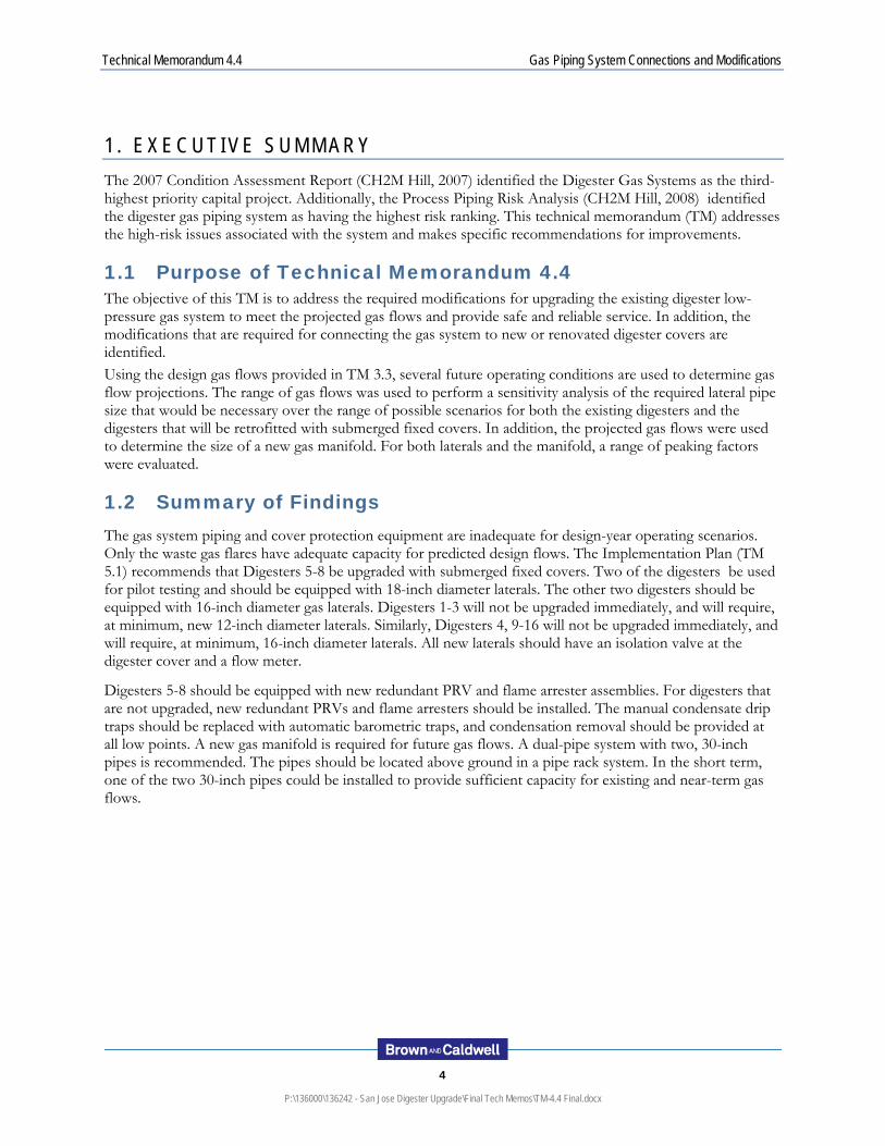
1 . E X E C U T I V E S U M M A R Y
The 2007 Condition Assessment Report (CH2M Hill, 2007) identified the Digester Gas Systems as the third-highest priority capital project. Additionally, the Process Piping Risk Analysis (CH2M Hill, 2008) identified the digester gas piping system as having the highest risk ranking. This technical memorandum (TM) addresses the high-risk issues associated with the system and makes specific recommendations for improvements.
1.1 Purpose of Technical Memorandum 4.4 The objective of this TM is to address the required modifications for upgrading the existing digester low-pressure gas system to meet the projected gas flows and provide safe and reliable service. In addition, the modifications that are required for connecting the gas system to new or renovated digester covers are identified. Using the design gas flows provided in TM 3.3, several future operating conditions are used to determine gas flow projections. The range of gas flows was used to perform a sensitivity analysis of the required lateral pipe size that would be necessary over the range of possible scenarios for both the existing digesters and the digesters that will be retrofitted with submerged fixed covers. In addition, the projected gas flows were used to determine the size of a new gas manifold. For both laterals and the manifold, a range of peaking factors were evaluated.
1.2 Summary of Findings The gas system piping and cover protection equipment are inadequate for design-year operating scenarios. Only the waste gas flares have adequate capacity for predicted design flows. The Implementation Plan (TM 5.1) recommends that Digesters 5-8 be upgraded with submerged fixed covers. Two of the digesters be used for pilot testing and should be equipped with 18-inch diameter laterals. The other two digesters should be equipped with 16-inch diameter gas laterals. Digesters 1-3 will not be upgraded immediately, and will require, at minimum, new 12-inch diameter laterals. Similarly, Digesters 4, 9-16 will not be upgraded immediately, and will require, at minimum, 16-inch diameter laterals. All new laterals should have an isolation valve at the digester cover and a flow meter.
Digesters 5-8 should be equipped with new redundant PRV and flame arrester assemblies. For digesters that are not upgraded, new redundant PRVs and flame arresters should be installed. The manual condensate drip traps should be replaced with automatic barometric traps, and condensation removal should be provided at all low points. A new gas manifold is required for future gas flows. A dual-pipe system with two, 30-inch pipes is recommended. The pipes should be located above ground in a pipe rack system. In the short term, one of the two 30-inch pipes could be installed to provide sufficient capacity for existing and near-term gas flows.

Technical Memorandum 4.4 Gas Piping System Connections and Modifications
5
P:\136000\136242 - San Jose Digester Upgrade\Final Tech Memos\TM-4.4 Final.docx
2 . I N T R O D U C T I O N
This TM describes the evaluation of digester gas system connections and modifications and provides recommendations for improvements as part of the rehabilitation of the digestion facilities at San Jose/Santa Clara Water Pollution Control Plant (WPCP).
2.1 Scope of Work The scope of work for Service Order No. 1 calls for review of the existing gas piping system and recommendations for connecting into the existing gas system from new and/or renovated digester covers; replacement of gas piping and appurtenances on the remaining existing digesters; removal of gas piping from tunnels; and connection of new gas piping to gas storage tanks and gas flares. Evaluation of gas utilization and treatment options is not part of this project. The scope of work includes evaluation of the following:
PRV replacement
Control valve type and locations
Gas piping valve isolation locations
Gas pressure monitoring requirements
Condensation collection
Gas flow metering type and locations
Gas sampling locations
Gas management system capacity based on the maximum capacity of the digesters including high strength waste from import materials which include fats, oils and grease (FOG) and plant scum and grease
Existing gas flares adequacy and capacity
Condition of existing gas piping in the tunnels
Alternatives to utilize the existing piping in the future.

Technical Memorandum 4.4 Gas Piping System Connections and Modifications
6
P:\136000\136242 - San Jose Digester Upgrade\Final Tech Memos\TM-4.4 Final.docx
3 . D E S C R I P T I O N O F E X I S T I N G L O W - P R E S S U R E D I G E S T E R G A S M A N A G E M E N T S Y S T E M
The digester gas system collects biogas produced from the anaerobic digestion process and transports, stores and manages the gas for utilization. The digester gas, combined with imported landfill gas and natural gas, is used as fuel for the WPCP’s cogeneration engines and engine-driven blowers. Excess gas is burned by the waste gas flares. Occasionally boilers are used as backup heat sources.
The digester gas flows from the digester cover gas well, through the lateral piping, to the main digester gas manifold. The main manifold supplies gas to the gas compressors upstream of the engines. The gas system consists of the digesters, gas storage, piping, piping appurtenances, engines, boilers, gas compressors, and waste gas flares. Each system component is described in detail in the following sections. The overall low-pressure gas collection system is shown schematically in Figure 3-1.
Figure 3-1. Low-pressure digester gas collection and storage at the WPCP
3.1 Digester Cover PRVs and Flame Arresters Each digester cover is equipped with a single PRV and flame arrester. This equipment protects the cover from damage due to over-pressurization or vacuum conditions. These PRVs are meant to operate in case of emergency only. To relieve pressure, the PRVs release digester gas into the atmosphere. The digester gas is flammable when mixed with air – for this reason, the flame arrester prevents an explosion or fire from propagating back into the digester. Vacuum relief allows air into the digester cover space. This occurs when the digester gas dome pressure is less than atmospheric pressure. Vacuum conditions occur if digester gas consumption exceeds production, or if sludge is withdrawn with the gas lateral isolation valve closed. Vacuum air relief can result in a flammable mixture and can compromise the anaerobic digestion process. The pressure setting for the PRV is the upper limit for gas system operating pressure. The PRVs are reportedly set at 9.5 inches water column (9.5” w.c.) (San Jose Online Operations and Maintenance Manual). This setting is typically based on the ballast weight and structural design rating of the cover.
Pressure relief valve portion of the PRVs are Anderson Greenwood Company, Type 93, 6-inch-diameter. The manufacturer’s listed capacity is approximately 1,260 standard cubic feet per minute (scfm). The vacuum relief valve portion of the PRVs are Anderson Greenwood Company, Type 96A, 6-inch-diameter. Listed
Drip Trap

Technical Memorandum 4.4 Gas Piping System Connections and Modifications
7
P:\136000\136242 - San Jose Digester Upgrade\Final Tech Memos\TM-4.4 Final.docx
capacity is approximately 730 scfm. The flame arresters are Varec Biogas, 5010 Series, 8-inch-diameter. The PRV assembly is shown in Figure 3-2.
As shown in Figure 3-2, the PRVs can be isolated for maintenance with a single plug valve. In this configuration, the cover has no relief valve protection when any of the components are out of service for maintenance. Current designs provide this extra protection by utilizing a dual PRV on three-way valves that allow isolation of one while maintaining the second active.
Figure 3-2. Typical digester cover PRVs with flame arrester
3.2 Digester Lateral Piping The digester lateral piping system connects each digester cover to the digester gas manifold and supplies gas to the compressor used for digester mixing. Each lateral contains an isolation valve, flexible rubber hose for floating cover travel, emergency shutoff valve, sediment trap, and flow meter. Pipe and hose diameter for Digesters 4-16 is 10 inches. Pipe and hose diameter for Digesters 1-3 is 8 inches. The components are shown in Figure 3-3.
PRV
Flame Arrester
Plug Valve

Technical Memorandum 4.4 Gas Piping System Connections and Modifications
8
P:\136000\136242 - San Jose Digester Upgrade\Final Tech Memos\TM-4.4 Final.docx
Figure 3-3. Schematic of a typical digester lateral and related equipment
3.2.1 Control Valve Type and Location
Each gas lateral includes an emergency shutoff control valve. This valve is normally open – it closes when the cover drops below the low cover level. If the cover continues to drop to the corbels – losing liquid seal – this valve functions to prevent gas from the other digesters and gas storage from escaping around the cover. The digester gas emergency shutoff control valves are Keystone Corporation, Model 504 or 700, pneumatically-actuated butterfly valves. The valve is shown in Figure 3-4.
Figure 3-4. Typical emergency shutoff control valve at the WPCP
3.2.2 Isolation Valve Type and Location
Each lateral includes a manual isolation valve on the digester cover. This valve can be used to isolate the digester from the rest of the system.

Technical Memorandum 4.4 Gas Piping System Connections and Modifications
9
P:\136000\136242 - San Jose Digester Upgrade\Final Tech Memos\TM-4.4 Final.docx
3.2.3 Sediment Trap
Each lateral includes a sediment trap, located at grade, for removal of condensation or entrained material in the gas. Figure 3-5 shows typical sediment trap location. After the sediment trap, the digester gas lateral enters the gallery and turns horizontal toward the digester gas flow meter and ultimately connects to the digester gas manifold.
Figure 3-5. Typical sediment trap at the WPCP
3.2.4 Condensation Collection
Digester gas is saturated with water as it leaves the digester. Condensation forms and collects as the gas cools from digester temperature to ambient temperature. Each lateral includes multiple provisions for condensation collection.
Lateral piping on the floating cover is sloped back toward the gas well, so any condensation in this piping drains back to the digester. The remainder of the above-grade piping drains to the sediment trap, which includes a drip trap at the bottom. Manual drip traps prevent gas from escaping while draining, but require an operator to open and close the valve.
Lateral piping in the gallery is drained via drip traps; however, traps are not always located at all low points. The most common location where drip traps are omitted is upstream of the digester gas flow meter. The flow meter, described below, is a reduced-diameter pipe spool located in a horizontal run as shown in Figure 3-6. Based on the pipe profile, condensation likely accumulates in these segments, filling the bottom of the pipe until it runs through the flow meter. There is inadequate condensation removal in the lateral upstream of the digester gas flow meters at Digesters 1-8, 10, 12, 14, 15 and 16. Only three digesters (9, 11, and 13) have upstream removal, although the drain for Digester 11 is not at the bottom-dead-center of the pipe, and Digester 13 has inadequate condensation removal downstream of the flow meter. Only Digester 9 had adequate condensation removal upstream and downstream of the flow meter.
Most of the drip traps are manual, which require operator attention for draining. Some of the traps have been modified with a barometric trap (water seal) so the valve can be left open and condensation can continuously overflow without releasing gas. A modified drip trap is shown in Figure 3-7.

Technical Memorandum 4.4 Gas Piping System Connections and Modifications
10
P:\136000\136242 - San Jose Digester Upgrade\Final Tech Memos\TM-4.4 Final.docx
Figure 3-6. Inadequate condensation removal upstream of flow meter at the WPCP
Figure 3-7. Manual drip trap modified with water seal at the WPCP
3.2.5 Flow Meters
Each lateral includes a digester gas flow meter. The flow meters are located in the piping gallery upstream of the lateral connection to the main manifold. The flow meters use differential pressure measurements to quantify gas flow. The meter is installed in a reduced-diameter pipe spool, which contains a cone-shaped insert. The flow meters are McCrometer V-Cones. Figure 3-8 shows a typical flow meter.
Flow Meter
Low point, no condensate removal

Technical Memorandum 4.4 Gas Piping System Connections and Modifications
11
P:\136000\136242 - San Jose Digester Upgrade\Final Tech Memos\TM-4.4 Final.docx
As discussed above, many of the digesters do not have condensation removal in the piping segment immediately upstream of the flow meter. The accumulation of water upstream of the meter can disrupt the inlet flow conditions or result in liquid carryover through the meter – both of which can result in measurement error.
Figure 3-8. Typical digester gas flow meter at the WPCP
3.2.6 Digester Manifold Piping
The digester gas manifold piping connects all of the digester laterals to the gas storage, flares and compressors. The majority of the manifold piping is located in the underground digester tunnels; the remainder – serving the gas storage and flares – is buried. The manifold is equipped with drip traps at low points. Digester manifold piping diameter is 24 inches, with some sections of 14-inch and 18-inch tributary manifold piping.
The manifold piping serving Digesters 1-4 and Digesters 9-12 was installed using mechanical couplings (Victaulic) to join pipe spools. These Victaulic connections have developed leaks; this type of coupling does not seal well in low-pressure gas applications. Plant staff has attempted to seal these joints, as shown in Figure 3-9, but the discoloration of the patch shows that this is not completely effective. Other joints that have not been patched are leaking condensation onto the tunnel floor, as shown in Figure 3-10.
The water leaking from the Victaulic joints shows that the joints are not water-tight, and presumably not gas-tight. The gallery is equipped with a combustible gas detection system as described in TM 4.3A. This system has not signaled an alarm recently – most likely because the gallery is well ventilated. Regardless, potential gas leakage presents a high risk, and as described in TM 4.3A, requires the tunnels be classified under National Fire Protection Associations (NFPA) Standard for Fire Protection in Wastewater Treatment and Collection Facilities (NFPA 820).

Technical Memorandum 4.4 Gas Piping System Connections and Modifications
12
P:\136000\136242 - San Jose Digester Upgrade\Final Tech Memos\TM-4.4 Final.docx
Figure 3-9. Digester gas manifold at the WPCP with a patched joint
Figure 3-10. Digester gas manifold at the WPCP with a leaky joint (left) and water accumulation below (right)
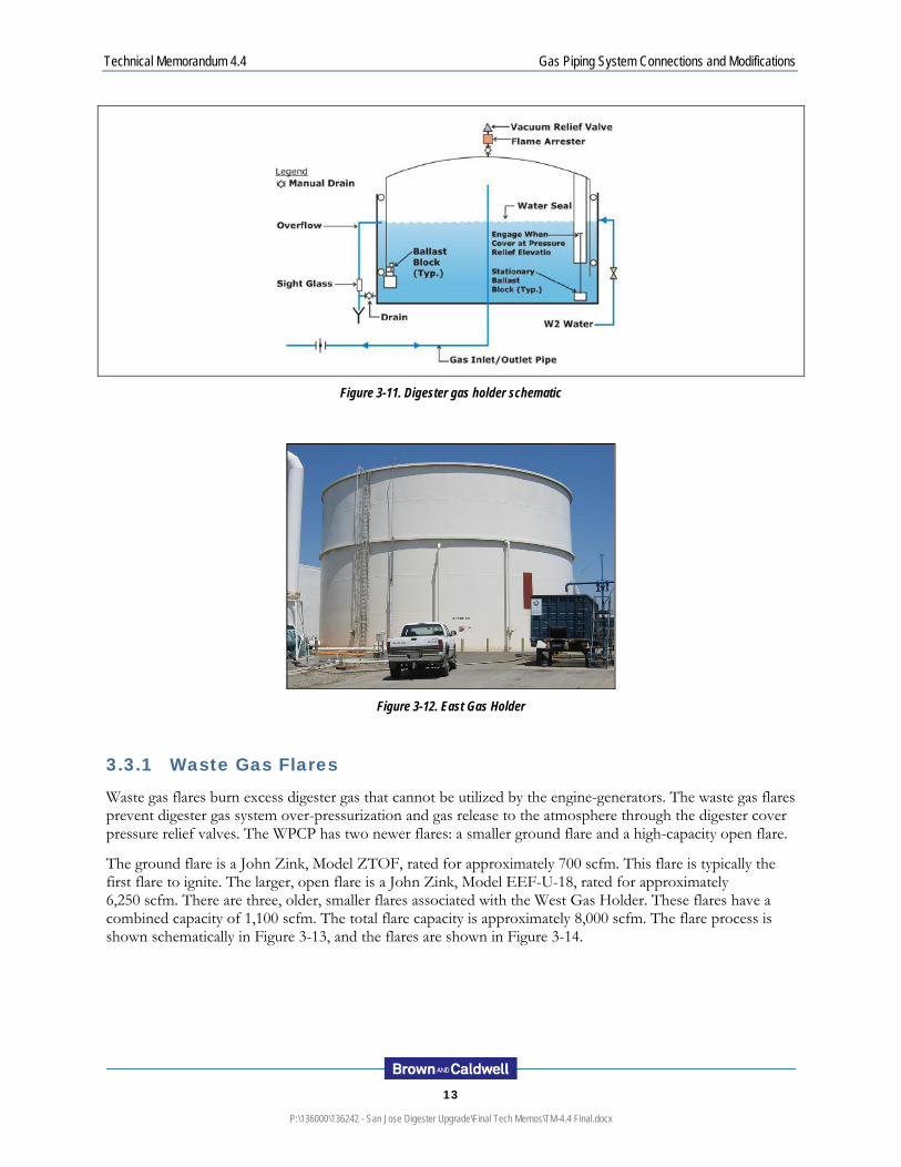
3.3 Digester Gas Storage The WPCP has two gas holders for low pressure digester gas storage and equalization. The primary gas holder (East Gas Holder) is a wet seal gas holder, consisting of an outer shell, inner piston, water seal, and stabilizing system. The floating piston provides 86,000 cubic feet (cf) of constant-pressure gas storage. The operating pressure is set by the amount of ballast on the piston. The gas holder currently operates at either 6.5” w.c. or 8.5” w.c., depending on gas holder cover level (cover picks up additional ballast as it rises). The second (West) gas holder, used only when the East gas holder is out of service, provides 4,200 cf of gas storage.
The gas holder level is used as the control parameter for digester gas system management. High level initiates the waste gas flares (ground flare on at 14.7 ft to 19.5 ft; open flare on at 19.5 ft and above). Low level reduces the output of the gas compressors (4 ft and below). In the “steady-state” intermediate range – 4 ft to 14.7 ft – the flares are off, the gas compressors supply the fuel needs for cogeneration, and the gas holder buffers variation in gas production. The primary gas holder is shown schematically in Figure 3-11 and pictured in Figure 3-12.
Technical Memorandum 4.4 Gas Piping System Connections and Modifications
13
P:\136000\136242 - San Jose Digester Upgrade\Final Tech Memos\TM-4.4 Final.docx
Figure 3-11. Digester gas holder schematic
Figure 3-12. East Gas Holder
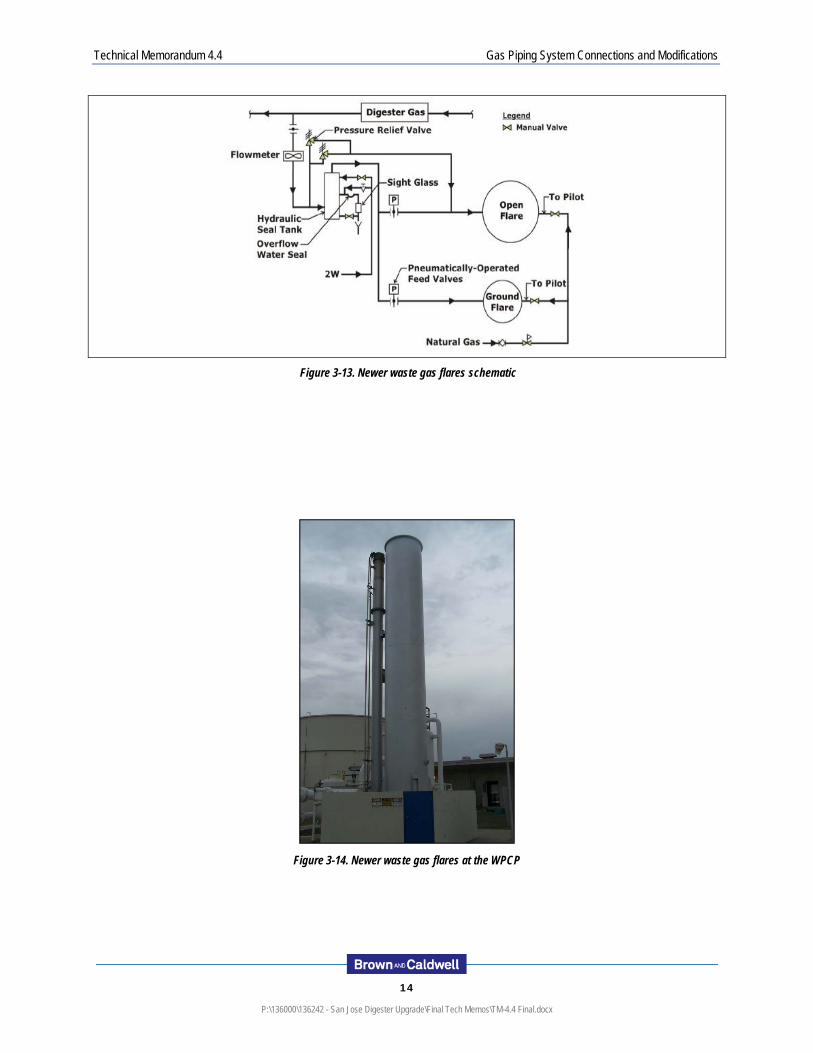
3.3.1 Waste Gas Flares
Waste gas flares burn excess digester gas that cannot be utilized by the engine-generators. The waste gas flares prevent digester gas system over-pressurization and gas release to the atmosphere through the digester cover pressure relief valves. The WPCP has two newer flares: a smaller ground flare and a high-capacity open flare.
The ground flare is a John Zink, Model ZTOF, rated for approximately 700 scfm. This flare is typically the first flare to ignite. The larger, open flare is a John Zink, Model EEF-U-18, rated for approximately 6,250 scfm. There are three, older, smaller flares associated with the West Gas Holder. These flares have a combined capacity of 1,100 scfm. The total flare capacity is approximately 8,000 scfm. The flare process is shown schematically in Figure 3-13, and the flares are shown in Figure 3-14.
Technical Memorandum 4.4 Gas Piping System Connections and Modifications
14
P:\136000\136242 - San Jose Digester Upgrade\Final Tech Memos\TM-4.4 Final.docx
Figure 3-13. Newer waste gas flares schematic
Figure 3-14. Newer waste gas flares at the WPCP

Technical Memorandum 4.4 Gas Piping System Connections and Modifications
15
P:\136000\136242 - San Jose Digester Upgrade\Final Tech Memos\TM-4.4 Final.docx
4 . D I G E S T E R G A S D E S I G N F L O W S
This section presents the design gas flow rates for sizing the laterals, PRVs, gas flares and gas manifold.
4.1 Gas System Design Rationale The gas system design is based on the projected gas production rates for 2030 as reported in TM 3.3. Additional analysis is included this this TM to address the potential for higher feed solids with DAFT co-thickening and operating at shorter HRTs. To account for future co-digestion import materials, the design condition is the 2030 loadings with the design quantity of import materials. However, two pilot digesters will test mixing, co-digestion, and other digestion operating modes and should be designed using the 2030 loadings assuming maximum quantity of import materials. This will provide the City flexibility to run the digesters with the maximum FOG loading (30 percent of the total VS loading).
Design gas flows for the laterals and PRVs are based on half the digesters operating as first stage thermophilic and half the digesters operating as either mesophilic with preprocessing or all digesters operating in a complete mix thermophilic mode (whichever is greater). These flows represent the most gas flow of any of the alternatives per digester, with the exception of the CambiTM process, which is not recommended at this time. The PRV and lateral requirements were determined for both the existing digesters (equipped with floating covers) and the digesters that will be equipped with submerged fixed covers, as recommended in TM 4.2.
The digester gas manifold and flares should be designed for the total gas production. The complete mix thermophilic alternative was used to size the gas manifold and flares. Since the manifold must be able to carry the total gas flow, it should be designed for the alternative that produces the most total gas production.
Peaking factors adjust the peak day gas flows to instantaneous flows to account for variability in digester gas production. A lateral gas peaking factor is necessary to avoid frequent uncontrolled gas releases. The planned upgrades to the WPCP digesters include loading to process maximums, including major contribution from FOG, which can increase gas peaks during uneven loading periods. This can be partially ameliorated if pre-digestion sludge storage is available to help dampen diurnal peaks; for example in primary sedimentation tanks and with controlled secondary sludge wasting. In addition, FOG and other co-digestion import materials require adequate storage to allow even feed throughout a given day.
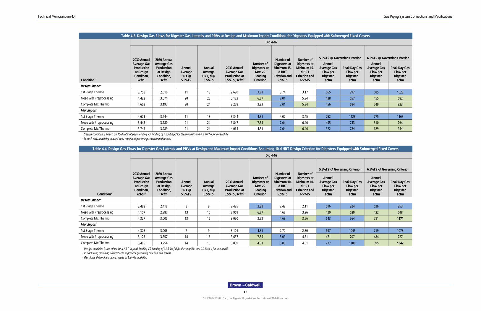
4.2 Design Gas Flows Tables 4-1 and 4-2 summarize the design gas flows for the laterals and PRVs for the two digester sizes equipped with the existing floating covers. Only the design import gas flows are presented because the digesters equipped with floating covers will not be used for pilot testing and therefore would not receive maximum import loadings. Tables 4-3 and 4-4 summarize the design gas flows for the laterals and PRVs for the digesters that will be upgraded with submerged fixed covers (Digesters 5-8). The design import gas flows are used to size equipment for the non-pilot digesters; the maximum import gas flows are used to size equipment for the pilot digesters.
Tables 4-1 and 4-3 summarizes the gas flows that were generated for each of the design conditions where the HRT criterion of 15-d is used. Table 4-2 and 4-4 summarize the gas flows that would result if the digesters were run at a 10-d HRT condition. In addition, all tables provide gas flows in the event future thickening upgrades produced a thicker sludge (6.5 percent TS) than the current design assumes (5.5 percent TS). This range of operating conditions was selected as a means to determine the range of possible operating scenarios for gas laterals, PRVs and the gas manifold.

Technical Memorandum 4.4 Gas Piping System Connections and Modifications
16
P:\136000\136242 - San Jose Digester Upgrade\Final Tech Memos\TM-4.4 Final.docx
The maximum potential gas production per digester is the basis for sizing the digester gas laterals and PRVs. For each individual digester, the maximum potential gas production is based on the maximum possible loading rate for the tank. This approach ensures that each digester’s auxiliary systems will not limit the sludge or other feedstock throughput. This is the approach used in other large digester complexes including EBMUD and Sacramento. For all conditions, the governing gas flow is the complete mixed thermophilic at a 10-d HRT and 6.5% TS thickened sludge concentration. These values were used to size all PRVs and laterals. A peaking factor of 1.75 (peak instantaneous:peak day) was used to size the PRVs and laterals.
This approach is also used for the gas manifold and flares, where the peak day gas production for complete mix thermophilic, the digestion alternative that produces the greatest total gas production, is used as a starting point, and different peaking factors are used for peak instantaneous. A peaking factor of 1.50 (peak instantaneous:peak day) was used to size the digester gas manifold and flares.

Technical Memorandum 4.4 Gas Piping System Connections and Modifications
17
P:\136000\136242 - San Jose Digester Upgrade\Final Tech Memos\TM-4.4 Final.docx
Table 4-1. Design Gas Flows for Digester Gas Laterals and PRVs at Design and Maximum Import Conditions for Existing Digesters Equipped with Floating Covers
Condition2
Dig 4-16 Dig 1-3
2030 Annual Average Gas Production at Design Condition,
kcf/d1
2030 Annual Average Gas Production at Design Condition,
scfm
Annual Average HRT @ 5.5%TS
Annual Average HRT, d @ 6.5%TS
2030 Annual Average Gas Production at 6.5%TS, scfm3
Number of Digesters at
Max VS Loading Criterion
Number of Digesters at Minimum 15-
d HRT Criterion and
5.5%TS
Number of Digesters at Minimum 15-
d HRT Criterion and
6.5%TS
5.5%TS @ Governing Criterion 6.5%TS @ Governing Criterion
5.5%TS @ Governing Criterion
6.5%TS @ Governing Criterion
Annual Average Gas
Flow per Digester,
scfm
Peak Day Gas Flow per Digester,
scfm
Annual Average Gas
Flow per Digester,
scfm
Peak Day Gas Flow per Digester,
scfm
Peak Day Gas Flow per Digester,
scfm
Peak Day Gas Flow per Digester,
scfm
Design Import
1st Stage Thermo 3,758 2,610 11 13 2,690 4.96 4.88 4.13 526 789 542 814 472 487
Meso with Preprocessing 4,422 3,071 21 24 3,122 8.68 8.86 7.50 347 520 360 540 311 323
Complete Mix Thermo 4,603 3,197 21 24 3,257 4.96 8.86 7.50 361 541 434 652 324 390 1 Design condition is based on 15-d HRT at peak loading VS loading of 0.35 lb/cf-d for thermophilic and 0.2 lb/cf-d for mesophilic 2 In each row, matching colored cells represent governing criterion and results
Table 4-2. Design Gas Flows for Digester Gas Laterals and PRVs at Design and Maximum Import Conditions Assuming 10-d HRT Design Criterion for Existing Digesters Equipped with Floating Covers
Condition2
Dig 4-16 Dig 1-3
2030 Annual Average Gas Production at Design Condition,
kcf/d1,3
2030 Annual Average Gas Production at Design Condition,
scfm
Annual Average HRT @ 5.5%TS
Annual Average HRT, d @ 6.5%TS
2030 Annual Average Gas Production at 6.5%TS, scfm3
Number of Digesters at
Max VS Loading Criterion
Number of Digesters at Minimum 10-
d HRT Criterion and
5.5%TS
Number of Digesters at Minimum 10-
d HRT Criterion and
6.5%TS
5.5%TS @ Governing Criterion 6.5%TS @ Governing Criterion
5.5%TS @ Governing Criterion
6.5%TS @ Governing Criterion
Annual Average Gas
Flow per Digester,
scfm
Peak Day Gas Flow per Digester,
scfm
Annual Average Gas
Flow per Digester,
scfm
Peak Day Gas Flow per Digester,
scfm
Peak Day Gas Flow per Digester,
scfm
Peak Day Gas Flow per Digester,
scfm
Design Import
1st Stage Thermo 3,482 2,418 8 9 2,495 4.96 3.26 2.75 488 731 503 755 438 451
Meso with Preprocessing 4,161 2,889 14 16 2,970 8.68 5.91 5.00 333 499 342 513 299 307
Complete Mix Thermo 4,331 3,008 14 16 3,092 4.96 5.91 5.00 509 764 619 928 457 555 1 Design condition is based on 10-d HRT at peak loading VS loading of 0.35 lb/cf-d for thermophilic and 0.2 lb/cf-d for mesophilic 2 In each row, matching colored cells represent governing criterion and results 3 Gas flows determined using results of BioWin modeling

Technical Memorandum 4.4 Gas Piping System Connections and Modifications
18
P:\136000\136242 - San Jose Digester Upgrade\Final Tech Memos\TM-4.4 Final.docx
Table 4-3. Design Gas Flows for Digester Gas Laterals and PRVs at Design and Maximum Import Conditions for Digesters Equipped with Submerged Fixed Covers
Condition2
Dig 4-16
2030 Annual Average Gas Production at Design Condition,
kcf/d1
2030 Annual Average Gas Production at Design Condition,
scfm
Annual Average HRT @ 5.5%TS
Annual Average HRT, d @ 6.5%TS
2030 Annual Average Gas Production at 6.5%TS, scfm3
Number of Digesters at
Max VS Loading Criterion
Number of Digesters at Minimum 15-
d HRT Criterion and
5.5%TS
Number of Digesters at Minimum 15-
d HRT Criterion and
6.5%TS
5.5%TS @ Governing Criterion 6.5%TS @ Governing Criterion
Annual Average Gas
Flow per Digester,
scfm
Peak Day Gas Flow per Digester,
scfm
Annual Average Gas
Flow per Digester,
scfm
Peak Day Gas Flow per Digester,
scfm
Design Import
1st Stage Thermo 3,758 2,610 11 13 2,690 3.93 3.74 3.17 665 997 685 1028
Meso with Preprocessing 4,422 3,071 20 23 3,123 6.87 7.01 5.94 438 657 455 682
Complete Mix Thermo 4,603 3,197 20 24 3,258 3.93 7.01 5.94 456 684 549 823
Max Import
1st Stage Thermo 4,671 3,244 11 13 3,344 4.31 4.07 3.45 752 1128 775 1163
Meso with Preprocessing 5,443 3,780 21 24 3,847 7.55 7.64 6.46 495 743 510 764
Complete Mix Thermo 5,745 3,989 21 24 4,064 4.31 7.64 6.46 522 784 629 944 1 Design condition is based on 15-d HRT at peak loading VS loading of 0.35 lb/cf-d for thermophilic and 0.2 lb/cf-d for mesophilic 2 In each row, matching colored cells represent governing criterion and results
Table 4-4. Design Gas Flows for Digester Gas Laterals and PRVs at Design and Maximum Import Conditions Assuming 10-d HRT Design Criterion for Digesters Equipped with Submerged Fixed Covers
Condition2
Dig 4-16
2030 Annual Average Gas Production at Design Condition,
kcf/d1,3
2030 Annual Average Gas Production at Design Condition,
scfm
Annual Average HRT @ 5.5%TS
Annual Average HRT, d @ 6.5%TS
2030 Annual Average Gas Production at 6.5%TS, scfm3
Number of Digesters at
Max VS Loading Criterion
Number of Digesters at Minimum 10-
d HRT Criterion and
5.5%TS
Number of Digesters at Minimum 10-
d HRT Criterion and
6.5%TS
5.5%TS @ Governing Criterion 6.5%TS @ Governing Criterion
Annual Average Gas
Flow per Digester,
scfm
Peak Day Gas Flow per Digester,
scfm
Annual Average Gas
Flow per Digester,
scfm
Peak Day Gas Flow per Digester,
scfm
Design Import
1st Stage Thermo 3,482 2,418 8 9 2,495 3.93 2.49 2.11 616 924 636 953
Meso with Preprocessing 4,157 2,887 13 16 2,969 6.87 4.68 3.96 420 630 432 648
Complete Mix Thermo 4,327 3,005 13 16 3,090 3.93 4.68 3.96 643 964 781 1171
Max Import
1st Stage Thermo 4,328 3,006 7 9 3,101 4.31 2.72 2.30 697 1045 719 1078
Meso with Preprocessing 5,123 3,557 14 16 3,657 7.55 5.09 4.31 471 707 484 727
Complete Mix Thermo 5,406 3,754 14 16 3,859 4.31 5.09 4.31 737 1106 895 1342 1 Design condition is based on 10-d HRT at peak loading VS loading of 0.35 lb/cf-d for thermophilic and 0.2 lb/cf-d for mesophilic 2 In each row, matching colored cells represent governing criterion and results 3 Gas flows determined using results of BioWin modeling

Technical Memorandum 4.4 Gas Piping System Connections and Modifications
19
P:\136000\136242 - San Jose Digester Upgrade\Final Tech Memos\TM-4.4 Final.docx
5 . E X I S T I N G S Y S T E M C A P A C I T Y
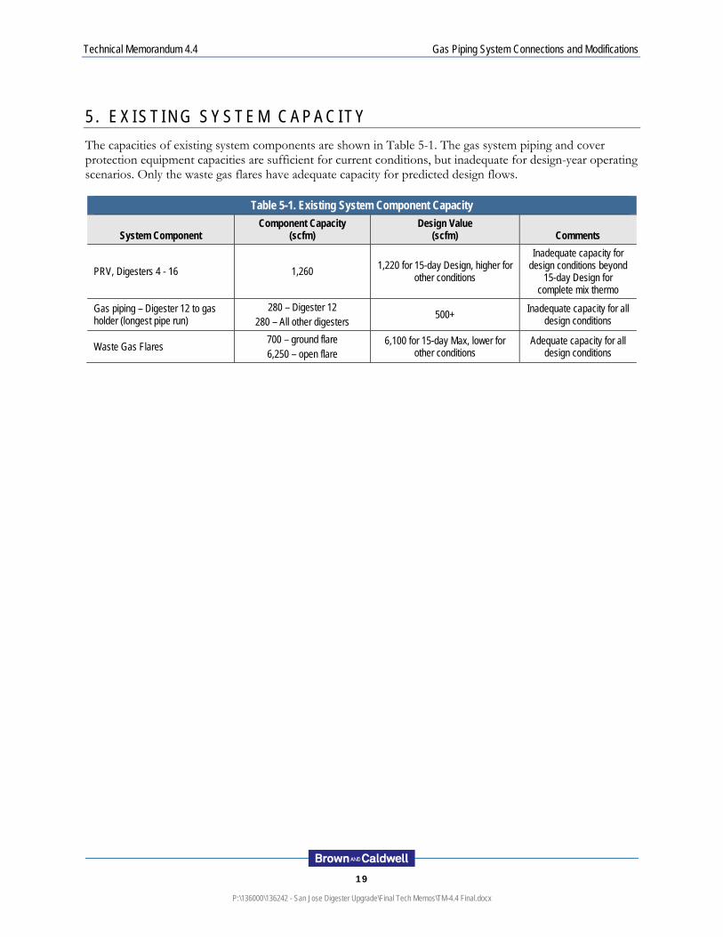
The capacities of existing system components are shown in Table 5-1. The gas system piping and cover protection equipment capacities are sufficient for current conditions, but inadequate for design-year operating scenarios. Only the waste gas flares have adequate capacity for predicted design flows.
Table 5-1. Existing System Component Capacity
System Component Component Capacity
(scfm) Design Value
(scfm) Comments
PRV, Digesters 4 - 16 1,260 1,220 for 15-day Design, higher for
other conditions
Inadequate capacity for design conditions beyond
15-day Design for complete mix thermo
Gas piping – Digester 12 to gas holder (longest pipe run)
280 – Digester 12 280 – All other digesters
500+ Inadequate capacity for all
design conditions
Waste Gas Flares 700 – ground flare 6,250 – open flare
6,100 for 15-day Max, lower for other conditions
Adequate capacity for all design conditions
Technical Memorandum 4.4 Gas Piping System Connections and Modifications
20
P:\136000\136242 - San Jose Digester Upgrade\Final Tech Memos\TM-4.4 Final.docx
6 . R E C O M M E N D E D I M P R O V E M E N T S
The following recommendations are made to remedy shortfalls between the existing system capacity and the design gas production. The recommendations also address observed deficiencies in the gas management system.
6.1 Connecting New or Rehabilitated Covers into the Existing Gas System
The following recommendations apply to digesters which are retrofitted with new or rehabilitated covers and mixing systems.
6.1.1 Digester Cover PRVs and Flame Arresters
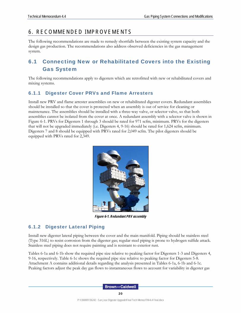
Install new PRV and flame arrester assemblies on new or rehabilitated digester covers. Redundant assemblies should be installed so that the cover is protected when an assembly is out of service for cleaning or maintenance. The assemblies should be installed with a three-way valve, or selector valve, so that both assemblies cannot be isolated from the cover at once. A redundant assembly with a selector valve is shown in Figure 6-1. PRVs for Digesters 1 through 3 should be rated for 971 scfm, minimum. PRVs for the digesters that will not be upgraded immediately (i.e. Digesters 4, 9-16) should be rated for 1,624 scfm, minimum. Digesters 7 and 8 should be equipped with PRVs rated for 2,049 scfm. The pilot digesters should be equipped with PRVs rated for 2,349.
Figure 6-1. Redundant PRV assembly
6.1.2 Digester Lateral Piping
Install new digester lateral piping between the cover and the main manifold. Piping should be stainless steel (Type 316L) to resist corrosion from the digester gas; regular steel piping is prone to hydrogen sulfide attack. Stainless steel piping does not require painting and is resistant to exterior rust.
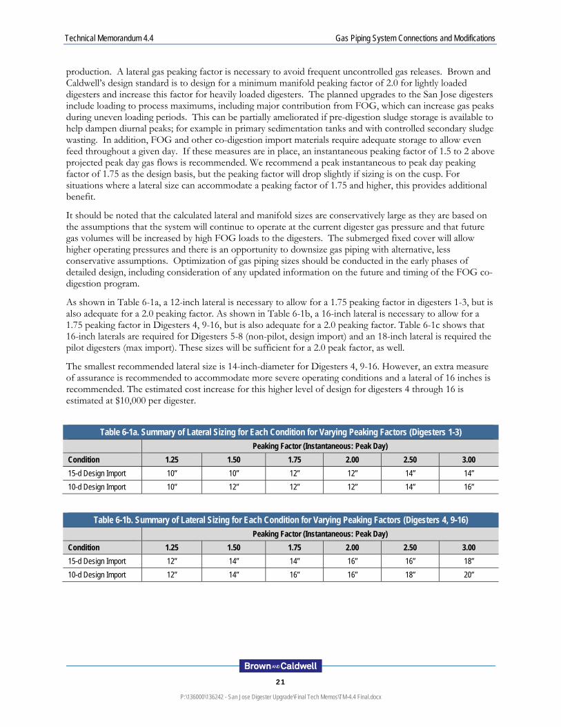
Tables 6-1a and 6-1b show the required pipe size relative to peaking factor for Digesters 1-3 and Digesters 4, 9-16, respectively. Table 6-1c shows the required pipe size relative to peaking factor for Digesters 5-8. Attachment A contains additional details regarding the analysis presented in Tables 6-1a, 6-1b and 6-1c. Peaking factors adjust the peak day gas flows to instantaneous flows to account for variability in digester gas
Technical Memorandum 4.4 Gas Piping System Connections and Modifications
21
P:\136000\136242 - San Jose Digester Upgrade\Final Tech Memos\TM-4.4 Final.docx
production. A lateral gas peaking factor is necessary to avoid frequent uncontrolled gas releases. Brown and Caldwell’s design standard is to design for a minimum manifold peaking factor of 2.0 for lightly loaded digesters and increase this factor for heavily loaded digesters. The planned upgrades to the San Jose digesters include loading to process maximums, including major contribution from FOG, which can increase gas peaks during uneven loading periods. This can be partially ameliorated if pre-digestion sludge storage is available to help dampen diurnal peaks; for example in primary sedimentation tanks and with controlled secondary sludge wasting. In addition, FOG and other co-digestion import materials require adequate storage to allow even feed throughout a given day. If these measures are in place, an instantaneous peaking factor of 1.5 to 2 above projected peak day gas flows is recommended. We recommend a peak instantaneous to peak day peaking factor of 1.75 as the design basis, but the peaking factor will drop slightly if sizing is on the cusp. For situations where a lateral size can accommodate a peaking factor of 1.75 and higher, this provides additional benefit.
It should be noted that the calculated lateral and manifold sizes are conservatively large as they are based on the assumptions that the system will continue to operate at the current digester gas pressure and that future gas volumes will be increased by high FOG loads to the digesters. The submerged fixed cover will allow higher operating pressures and there is an opportunity to downsize gas piping with alternative, less conservative assumptions. Optimization of gas piping sizes should be conducted in the early phases of detailed design, including consideration of any updated information on the future and timing of the FOG co-digestion program.
As shown in Table 6-1a, a 12-inch lateral is necessary to allow for a 1.75 peaking factor in digesters 1-3, but is also adequate for a 2.0 peaking factor. As shown in Table 6-1b, a 16-inch lateral is necessary to allow for a 1.75 peaking factor in Digesters 4, 9-16, but is also adequate for a 2.0 peaking factor. Table 6-1c shows that 16-inch laterals are required for Digesters 5-8 (non-pilot, design import) and an 18-inch lateral is required the pilot digesters (max import). These sizes will be sufficient for a 2.0 peak factor, as well.
The smallest recommended lateral size is 14-inch-diameter for Digesters 4, 9-16. However, an extra measure of assurance is recommended to accommodate more severe operating conditions and a lateral of 16 inches is recommended. The estimated cost increase for this higher level of design for digesters 4 through 16 is estimated at $10,000 per digester.
Table 6-1a. Summary of Lateral Sizing for Each Condition for Varying Peaking Factors (Digesters 1-3)
Peaking Factor (Instantaneous: Peak Day)
Condition 1.25 1.50 1.75 2.00 2.50 3.00
15-d Design Import 10” 10” 12” 12” 14” 14”
10-d Design Import 10” 12” 12” 12” 14” 16”
Table 6-1b. Summary of Lateral Sizing for Each Condition for Varying Peaking Factors (Digesters 4, 9-16)
Peaking Factor (Instantaneous: Peak Day)
Condition 1.25 1.50 1.75 2.00 2.50 3.00
15-d Design Import 12” 14” 14” 16” 16” 18”
10-d Design Import 12” 14” 16” 16” 18” 20”

Technical Memorandum 4.4 Gas Piping System Connections and Modifications
22
P:\136000\136242 - San Jose Digester Upgrade\Final Tech Memos\TM-4.4 Final.docx
Table 6-1c. Summary of Lateral Sizing for Each Condition for Varying Peaking Factors (Digesters 5-8)
Peaking Factor (Instantaneous: Peak Day)
Condition 1.25 1.50 1.75 2.00 2.50 3.00
15-d Design Import (Non-pilot) 14" 14" 16" 16" 18" 20"
15-d Max Import (Pilot)) 14" 16" 16" 18" 20" 20"
10-d Design Import (Non-pilot) 14" 14" 16" 16" 18" 20"
10-d Max Import (Pilot) 14" 16" 18" 18" 20" 24"
6.1.2.1 Control Valve
An emergency shutoff control valve is optional, and is only applicable for new/rehabilitated floating cover digesters. The control valve protects against a loss of digester gas in the event that a floating cover unexpectedly drops below normal operating range. A more proactive approach would include alarms and control logic to alert operators when cover level drops and to stop withdrawal from the digester. If the cover still drops, the digester can be isolated from the rest of the gas system by manually closing a lateral isolation valve at the manifold.
6.1.2.2 Isolation Valves and Locations
Each new lateral should include an isolation valve at the digester cover. Additionally, a lateral isolation valve is recommended at the manifold piping to facilitate construction sequencing or provide a safe shut-off location in the event of cover failure.
6.1.2.3 Sediment Trap
Whether or not sediment/foam traps are recommended depends on cover selection. Some cover types place the digester gas draw-off closer to the sludge liquid surface than others. This increases the likelihood of foam or liquid carryover into the gas piping. In this case, a sediment/foam trap may be beneficial. Floating covers and submerged fixed covers have less clear space and are candidates for sediment traps. Non-submerged fixed covers have much greater clear space and may not require sediment traps because foam and entrained sludge are less likely to reach the draw-off piping. Sediment/foam traps are sized based on diameter of connecting piping and/or digester gas flow.
6.1.2.4 Condensation Collection
Each new digester lateral will be sloped to low points with condensation draw-off points. Condensation should be collected and managed without the need for operator attention. Condensate tanks with a barometric trap are a simple way to automatically overflow condensation without releasing digester gas. These traps do not require frequent operator attention. Condensate tanks can be located in the digester gallery if the associated vent pipe is routed above grade. A barometric-trap condensate tank is shown in Figure 6-2.

Technical Memorandum 4.4 Gas Piping System Connections and Modifications
23
P:\136000\136242 - San Jose Digester Upgrade\Final Tech Memos\TM-4.4 Final.docx
Figure 6-2. Condensate tank
6.1.2.5 Flow Meters and Instrumentation
Each lateral should include a digester gas flow meter for measurement of digester gas production. The existing differential pressure flow meters are suitable for digester gas application, but the associated reduced-diameter pipe spool and cone-shaped obstruction create unnecessary pressure loss in the piping. Important characteristics of digester gas flow meters are:
Low detection velocity
Wide velocity range
Low pressure loss
Not influenced by moisture and contaminants in the gas
The main options for digester gas flow measurement are differential pressure-based meters, thermal dispersion meters, and vortex shedding meters. The existing differential pressure meters have good velocity range, but have a higher pressure loss and potential for fouling and plugging due to the reduced-diameter pipe spool and cone-shaped obstruction. Many facilities use thermal dispersion, insertion-type flow meters for digester gas flow measurement. These flow meters are the least invasive, induce the least pressure loss, and are easily removable for inspection and maintenance without taking the lateral out of service. Some installations report problems with moisture in the digester gas, but this issue can be mitigated with upstream condensate removal and proper orientation of the meter (sticking up into the pipe at a 45-degree angle so condensation runs away from the probe). Vortex shedding meters typically require conditions with a high Reynolds number. This can require reduced-diameter piping to increase velocity. The reduction increases pressure loss though, and vortex shedding meters have recently shown problems at other facilities.
Digester gas pressure should be monitored in each digester gas dome. In addition, one pressure sensor should be installed in each manifold pipe.
Technical Memorandum 4.4 Gas Piping System Connections and Modifications
24
P:\136000\136242 - San Jose Digester Upgrade\Final Tech Memos\TM-4.4 Final.docx
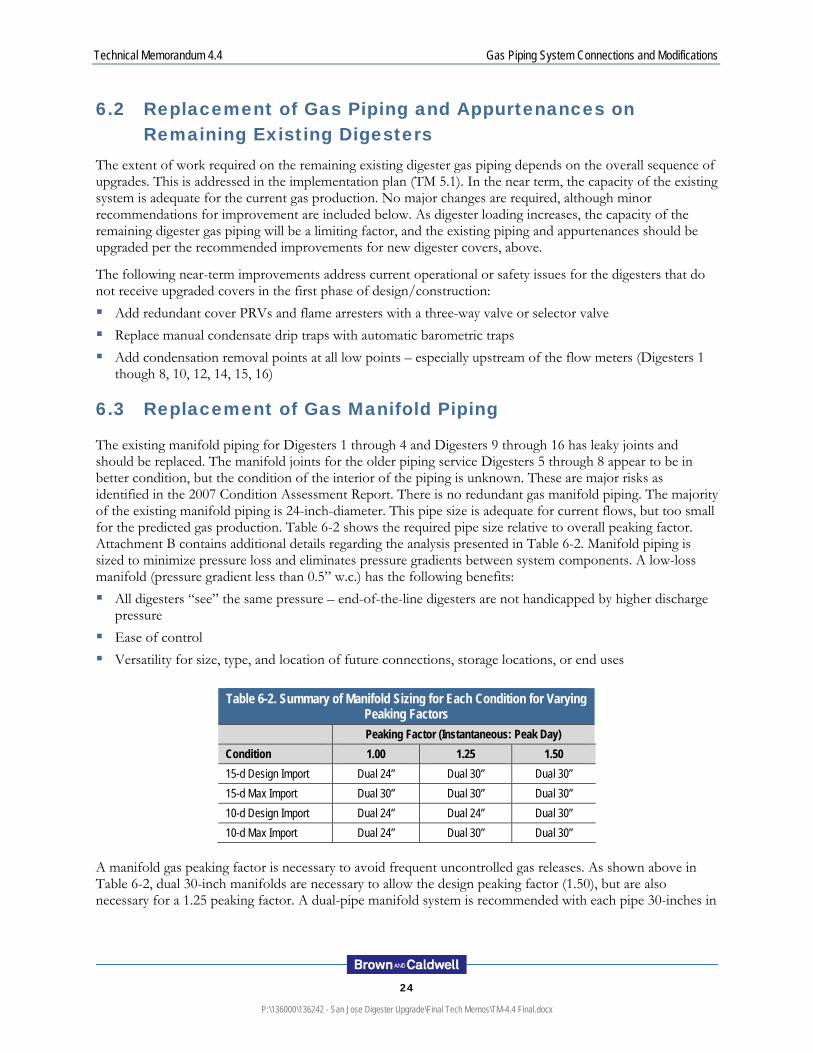
6.2 Replacement of Gas Piping and Appurtenances on Remaining Existing Digesters
The extent of work required on the remaining existing digester gas piping depends on the overall sequence of upgrades. This is addressed in the implementation plan (TM 5.1). In the near term, the capacity of the existing system is adequate for the current gas production. No major changes are required, although minor recommendations for improvement are included below. As digester loading increases, the capacity of the remaining digester gas piping will be a limiting factor, and the existing piping and appurtenances should be upgraded per the recommended improvements for new digester covers, above.
The following near-term improvements address current operational or safety issues for the digesters that do not receive upgraded covers in the first phase of design/construction:
Add redundant cover PRVs and flame arresters with a three-way valve or selector valve
Replace manual condensate drip traps with automatic barometric traps
Add condensation removal points at all low points – especially upstream of the flow meters (Digesters 1 though 8, 10, 12, 14, 15, 16)
6.3 Replacement of Gas Manifold Piping
The existing manifold piping for Digesters 1 through 4 and Digesters 9 through 16 has leaky joints and should be replaced. The manifold joints for the older piping service Digesters 5 through 8 appear to be in better condition, but the condition of the interior of the piping is unknown. These are major risks as identified in the 2007 Condition Assessment Report. There is no redundant gas manifold piping. The majority of the existing manifold piping is 24-inch-diameter. This pipe size is adequate for current flows, but too small for the predicted gas production. Table 6-2 shows the required pipe size relative to overall peaking factor. Attachment B contains additional details regarding the analysis presented in Table 6-2. Manifold piping is sized to minimize pressure loss and eliminates pressure gradients between system components. A low-loss manifold (pressure gradient less than 0.5” w.c.) has the following benefits:
All digesters “see” the same pressure – end-of-the-line digesters are not handicapped by higher discharge pressure
Ease of control
Versatility for size, type, and location of future connections, storage locations, or end uses
Table 6-2. Summary of Manifold Sizing for Each Condition for Varying Peaking Factors
Peaking Factor (Instantaneous: Peak Day)
Condition 1.00 1.25 1.50
15-d Design Import Dual 24” Dual 30” Dual 30”
15-d Max Import Dual 30” Dual 30” Dual 30”
10-d Design Import Dual 24” Dual 24” Dual 30”
10-d Max Import Dual 24” Dual 30” Dual 30”
A manifold gas peaking factor is necessary to avoid frequent uncontrolled gas releases. As shown above in Table 6-2, dual 30-inch manifolds are necessary to allow the design peaking factor (1.50), but are also necessary for a 1.25 peaking factor. A dual-pipe manifold system is recommended with each pipe 30-inches in
Technical Memorandum 4.4 Gas Piping System Connections and Modifications
25
P:\136000\136242 - San Jose Digester Upgrade\Final Tech Memos\TM-4.4 Final.docx
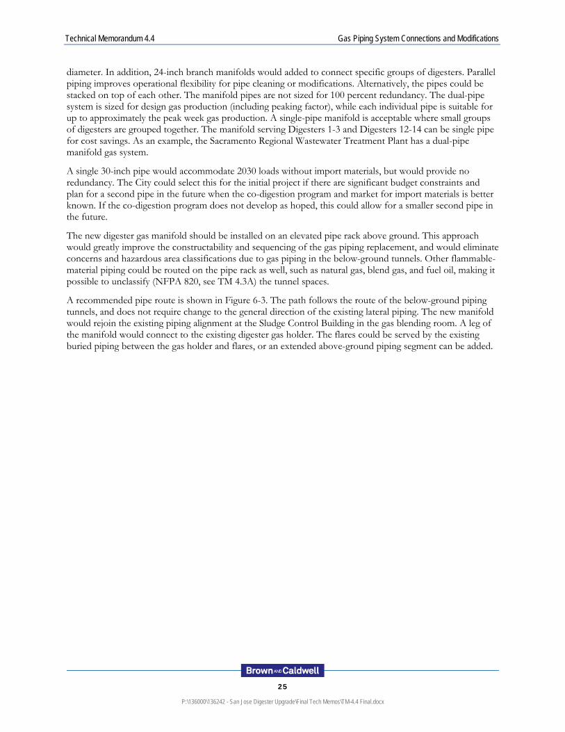
diameter. In addition, 24-inch branch manifolds would added to connect specific groups of digesters. Parallel piping improves operational flexibility for pipe cleaning or modifications. Alternatively, the pipes could be stacked on top of each other. The manifold pipes are not sized for 100 percent redundancy. The dual-pipe system is sized for design gas production (including peaking factor), while each individual pipe is suitable for up to approximately the peak week gas production. A single-pipe manifold is acceptable where small groups of digesters are grouped together. The manifold serving Digesters 1-3 and Digesters 12-14 can be single pipe for cost savings. As an example, the Sacramento Regional Wastewater Treatment Plant has a dual-pipe manifold gas system.
A single 30-inch pipe would accommodate 2030 loads without import materials, but would provide no redundancy. The City could select this for the initial project if there are significant budget constraints and plan for a second pipe in the future when the co-digestion program and market for import materials is better known. If the co-digestion program does not develop as hoped, this could allow for a smaller second pipe in the future.
The new digester gas manifold should be installed on an elevated pipe rack above ground. This approach would greatly improve the constructability and sequencing of the gas piping replacement, and would eliminate concerns and hazardous area classifications due to gas piping in the below-ground tunnels. Other flammable-material piping could be routed on the pipe rack as well, such as natural gas, blend gas, and fuel oil, making it possible to unclassify (NFPA 820, see TM 4.3A) the tunnel spaces.
A recommended pipe route is shown in Figure 6-3. The path follows the route of the below-ground piping tunnels, and does not require change to the general direction of the existing lateral piping. The new manifold would rejoin the existing piping alignment at the Sludge Control Building in the gas blending room. A leg of the manifold would connect to the existing digester gas holder. The flares could be served by the existing buried piping between the gas holder and flares, or an extended above-ground piping segment can be added.

Technical Memorandum 4.4 Gas Piping System Connections and Modifications
26
P:\136000\136242 - San Jose Digester Upgrade\Final Tech Memos\TM-4.4 Final.docx
Figure 6-3. Above-ground gas manifold alignment

Technical Memorandum 4.4 Gas Piping System Connections and Modifications
27
P:\136000\136242 - San Jose Digester Upgrade\Final Tech Memos\TM-4.4 Final.docx
The pipe and rack will be elevated at all road crossings to CalTrans minimum clearance for all road-worthy traffic. The new pipe rack design will require special considerations at the Zanker Lane crossing where high voltage power lines parallel the road. The lines appear high enough to provide adequate clearance over the pipe while still allowing for traffic clearance under the pipe. Appropriate grounding systems should be included in detailed design. As an alternative, pipes could be buried for road crossings, but would this would require a condensate removal system including an access vault.
As discussed for digester gas lateral piping, the manifold material should be stainless steel, Type 316L. Stainless steel piping is more corrosion-resistant than plain steel, especially for digester gas contaminants such as moisture and hydrogen sulfide. Piping connections should be flanged or welded. Victaulic connections are not suitable for low-pressure gas applications. The manifold should be sloped to low points for condensate removal: 1/8-inch per foot with the direction of flow, and 1/4-inch per foot against the direction of flow.
Technical Memorandum 4.4 Gas Piping System Connections and Modifications
28
P:\136000\136242 - San Jose Digester Upgrade\Final Tech Memos\TM-4.4 Final.docx
7 . R E C O M M E N D A T I O N S
A review of the existing gas piping system was performed and deficiencies were identified. The gas system piping and cover protection equipment are sufficient for current conditions, but inadequate for design-year operating scenarios. Only the waste gas flares have adequate capacity for predicted design flows.
Several recommendations were made to upgrade existing equipment. In addition, the gas production values for several alternatives were used to determine the requirements for new gas piping and appurtenances. The following recommendations are made as result of this analysis.
For Digesters 1-3 and Digesters 4, 9-16, the following is recommended.
Add redundant PRVs and flame arresters.
Install, at minimum, new 12-inch diameter laterals for Digesters 1-3 and 16-inch diameter laterals for Digesters 4, 9-16. Each lateral should have an isolation valve and pressure sensor at the digester cover and an insertion flow meter.
Replace manual condensate drip traps with automatic barometric traps.
Add condensation removal points at all low points.
For Digesters 5-8, the following is recommended.
Install new redundant PRV and flame arrester assemblies. For Digesters 5-8, non-pilot digesters should be equipped with 16-inch laterals and pilot digesters should be equipped with 18-inch laterals. Each lateral should have an isolation valve and pressure sensor at the digester cover and an insertion flow meter. A new, dual-pipe system (30-inch pipes) gas manifold is required for future gas flows. In addition, 24-inch branch manifolds would be added to connect specific groups of digesters. A single 30-inch pipe would accommodate 2030 loads without import materials, but would provide no redundancy. The pipes should be located above ground in a pipe rack system. Pipes could be buried for road crossing, but would require condensate removal system including an access vault. Other flammable-material piping could be routed on the pipe rack as well, such as natural gas, blend gas, and fuel oil, making it possible to unclassify (NFPA 820, see TM 4.3A) the tunnel spaces. In the short term, one of the two 30-inch pipes could be installed to provide sufficient capacity for existing and near-term gas flows.
It should be noted that these recommended lateral and manifold sizes are conservatively large as they are based on the assumptions that the system will continue to operate at the current digester gas pressure and that future gas volumes will be increased by high FOG loads to the digesters. The submerged fixed cover will allow higher operating pressures and there is an opportunity to downsize gas piping with alternative, less conservative assumptions. Optimization of gas piping sizes should be conducted in the early phases of detailed design, including consideration of any updated information on the future and timing of the FOG co-digestion program.

Technical Memorandum 4.4 Gas Piping System Connections and Modifications
29
P:\136000\136242 - San Jose Digester Upgrade\Final Tech Memos\TM-4.4 Final.docx
8 . R E F E R E N C E S
CH2M- Hill, May 2007, San Jose – Santa Clara WPCP Infrastructure Condition Assessment Report
CH2M- Hill, May 2008, San Jose – Santa Clara WPCP Process Piping Assessment


Gas Piping System Connections and Modifications
A
P:\136000\136242 - San Jose Digester Upgrade\Final Tech Memos\TM-4.4 Final.docx
ATTACHMENT A


Gas Piping System Connections and Modifications
A
P:\136000\136242 - San Jose Digester Upgrade\Final Tech Memos\TM-4.4 Final.docx
Lateral Sizing for Digesters 4, 9-16 as a Function of Peaking Factor (15-d design HRT at Design Import Loadings for 2030)
Lateral Sizing for Digesters 4, 9-16 as a Function of Peaking Factor (10-d design HRT at Design Import Loadings for 2030)
1.00
1.25
1.50
1.75
2.00
2.25
2.50
2.75
3.00
0 250 500 750 1,000 1,250 1,500 1,750 2,000 2,250 2,500 2,750
Pe
ak
Ins
tan
tan
eou
s:P
eak
Da
y P
ea
kin
g F
ac
tor
Gas Flow, scfm
1st Stage Thermo 5.5%
1st Stage Thermo 6.5%
Meso w/ Preprocessing 5.5%
Meso w/ Preprocessing 6.5%
Complete Mix Thermo 5.5 %
Complete Mix Thermo 6.5 %
18-inch16-inch14-inch12-inch10-inch

Gas Piping System Connections and Modifications
A
P:\136000\136242 - San Jose Digester Upgrade\Final Tech Memos\TM-4.4 Final.docx
Lateral Sizing for Digesters 5-8 (pilot digesters, maximum import) as a Function of Peaking Factor (15-d design HRT at Maximum Import Loadings for 2030)
Lateral Sizing for Digesters 5-8(pilot digesters maximum import) as a Function of Peaking Factor (10-d design HRT at Maximum Import Loadings for 2030)
1.00
1.25
1.50
1.75
2.00
2.25
2.50
2.75
3.00
0 250 500 750 1,000 1,250 1,500 1,750 2,000 2,250 2,500 2,750
Pe
ak
Ins
tan
tan
eou
s:P
eak
Da
y P
ea
kin
g F
ac
tor
Gas Flow, scfm
1st Stage Thermo 5.5%
1st Stage Thermo 6.5%
Meso w/ Preprocessing 5.5%
Meso w/ Preprocessing 6.5%
Complete Mix Thermo 5.5 %
Complete Mix Thermo 6.5 %
18-inch16-inch14-inch12-inch10-inch
Gas Piping System Connections and Modifications
A
P:\136000\136242 - San Jose Digester Upgrade\Final Tech Memos\TM-4.4 Final.docx
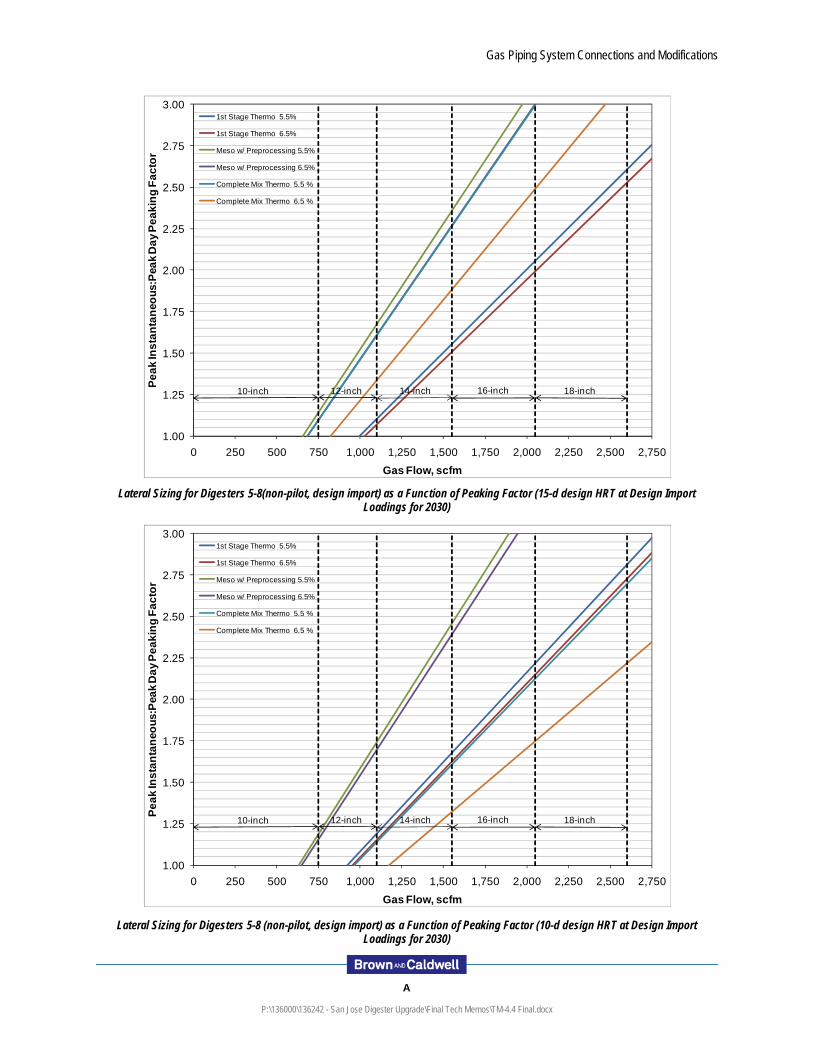
Lateral Sizing for Digesters 5-8(non-pilot, design import) as a Function of Peaking Factor (15-d design HRT at Design Import Loadings for 2030)
Lateral Sizing for Digesters 5-8 (non-pilot, design import) as a Function of Peaking Factor (10-d design HRT at Design Import Loadings for 2030)
1.00
1.25
1.50
1.75
2.00
2.25
2.50
2.75
3.00
0 250 500 750 1,000 1,250 1,500 1,750 2,000 2,250 2,500 2,750
Pe
ak
Ins
tan
tan
eou
s:P
eak
Da
y P
ea
kin
g F
ac
tor
Gas Flow, scfm
1st Stage Thermo 5.5%
1st Stage Thermo 6.5%
Meso w/ Preprocessing 5.5%
Meso w/ Preprocessing 6.5%
Complete Mix Thermo 5.5 %
Complete Mix Thermo 6.5 %
18-inch16-inch14-inch12-inch10-inch


Gas Piping System Connections and Modifications
B
P:\136000\136242 - San Jose Digester Upgrade\Final Tech Memos\TM-4.4 Final.docx
ATTACHMENT B

Gas Piping System Connections and Modifications
B
P:\136000\136242 - San Jose Digester Upgrade\Final Tech Memos\TM-4.4 Final.docx
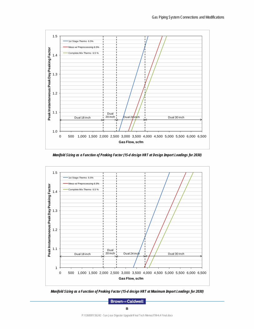
Manifold Sizing as a Function of Peaking Factor (15-d design HRT at Design Import Loadings for 2030)
Manifold Sizing as a Function of Peaking Factor (15-d design HRT at Maximum Import Loadings for 2030)
1.0
1.1
1.2
1.3
1.4
1.5
0 500 1,000 1,500 2,000 2,500 3,000 3,500 4,000 4,500 5,000 5,500 6,000 6,500
Pe
ak
Ins
tan
tan
eou
s:P
eak
Da
y P
ea
kin
g F
ac
tor
Gas Flow, scfm
1st Stage Thermo 6.5%
Meso w/ Preprocessing 6.5%
Complete Mix Thermo 6.5 %
Dual 18 inchDual
20 inch Dual 24 inch Dual 30 inch
1
1.1
1.2
1.3
1.4
1.5
0 500 1,000 1,500 2,000 2,500 3,000 3,500 4,000 4,500 5,000 5,500 6,000 6,500
Pe
ak
Ins
tan
tan
eou
s:P
eak
Da
y P
ea
kin
g F
ac
tor
Gas Flow, scfm
1st Stage Thermo 6.5%
Meso w/ Preprocessing 6.5%
Complete Mix Thermo 6.5 %
Dual 18 inchDual
20 inch Dual 24 inch Dual 30 inch

Gas Piping System Connections and Modifications
B
P:\136000\136242 - San Jose Digester Upgrade\Final Tech Memos\TM-4.4 Final.docx
Manifold Sizing as a Function of Peaking Factor (10-d design HRT at Design Import Loadings for 2030)
Manifold Sizing as a Function of Peaking Factor (10-d design HRT at Maximum Import Loadings for 2030)
1
1.1
1.2
1.3
1.4
1.5
0 500 1,000 1,500 2,000 2,500 3,000 3,500 4,000 4,500 5,000 5,500 6,000 6,500
Pe
ak
Ins
tan
tan
eou
s:P
eak
Da
y P
ea
kin
g F
ac
tor
Gas Flow, scfm
1st Stage Thermo 6.5%
Meso w/ Preprocessing 6.5%
Complete Mix Thermo 6.5 %
Dual 18 inchDual
20 inch Dual 24 inch Dual 30 inch
1
1.1
1.2
1.3
1.4
1.5
0 500 1,000 1,500 2,000 2,500 3,000 3,500 4,000 4,500 5,000 5,500 6,000 6,500
Pe
ak
Ins
tan
tan
eou
s:P
eak
Da
y P
ea
kin
g F
ac
tor
Gas Flow, scfm
1st Stage Thermo 6.5%
Meso w/ Preprocessing 6.5%
Complete Mix Thermo 6.5 %
Dual 18 inchDual
20 inch Dual 24 inch Dual 30 inch