Embed Size (px)
Citation preview

1
T ECH N ICA L M A N UA LUNIT AND DIRECT MAINTENANCE MANUALINCLUDING REPAIR PARTS AND SPECIAL TOOLS LIST
M60D, 7.62 M M , M AC H I N E GU N

2
U.S . ORDN A NCE
M60DPROVEN UNDER FIRE

3
The M60D Series Machine Guns should be inspected and gauged at least once annually for safety and serviceability. Initial gauging is required one year from receipt of the weapons.
A two year interval may be maintained by some units unless preventive maintenance checks and services (PMCS) or other physical evidence indicates that an individual unit’s M60D Machine Guns require inspection/gauging at a more frequent interval. If it is determined that a yearly inspection is necessary for an individual unit, only that unit will be affected. That will not affect other units in regard to the interval of inspection. Dry cleaning solvent (SD) is flammable.
Do not clean parts near an open flame or in a smoking area. Dry cleaning solvent evaporates quickly and has a drying effect on the skin. When used without protective gloves, solvent may cause irritation to or cracking of the skin.
Personnel operating vapor degreaser are warned not to breathe the vapor fumes.
Before starting an inspection, be sure to clear the weapon. Do not actuate the trigger before clearing the weapon. Inspect the chamber to make sure it is empty and free of obstructions. Check to see there are no obstructions in the barrel and no ammunition is in position to be chambered.
Using paint thinners, gasoline, kerosene, benzene (benzol), water, steam, or air for cleaning the weapon is prohibited. Use only authorized cleaning materials.
Be careful when removing and installing spring-loaded components. Carelessness could cause injury.
To prevent possible body injuries and aircraft damage, personnel should not stand the weapon on its barrel assembly when disassembling or assembling the weapon.
WARNING
U.S. Ordnance | M60D 7.62MM Machine Gun | Technical Manual

4
WARNING PAGE
CHAPTER 1 INTRODUCTIONGeneral InformationEquipment Description and Data
CHAPTER 2 UNIT MAINTENANCE INSTRUCTIONSRepair Parts, Special Tools, and Support EquipmentService Upon ReceiptPreventive Maintenance Checks and Services (PMCS)TroubleshootingMaintenance ProceduresMaintenance: Grip and Trigger AssemblyMaintenance: Breech Bolt AssemblyMaintenance: Operating Rod AssemblyMaintenance: Sear and Safety Housing AssemblyMaintenance: Barrel and Carry Handle AssemblyMaintenance: Cover Assembly Maintenance: Cartridge Feed Tray Assembly Lubrication InstructionsPreparation for Storage or Shipment
CHAPTER 3 DIRECT MAINTENANCE INSTRUCTIONSRepair Parts, Special tools and Support Equipment Troubleshooting Maintenance ProceduresMaintenance: M60D Machine Gun (Section 1 of 2) Maintenance: M60D Machine Gun (Section 2 of 2) Maintenance: Breech Bolt Assembly Maintenance: Breech Bolt Assembly Maintenance: BarrelMaintenance: BipodMaintenance: Bipod LegsMaintenance: Cover AssemblyMaintenance: Feed Cam AssemblyMaintenance: Feed Lever AssemblyMaintenance: Feed Pawl Assembly Maintenance: Cover Housing Assembly Maintenance: Rear SightMaintenance: Cocking Handle AssemblyMaintenance: Gun Receiver AssemblyPreembarking Inspection of Material Units Alerted for Overseas MovementPreparation for Storage or Shipment
0102
0304050607080910111213141516
pg. 2pg. 3
pg. 7pg. 8pg. 10pg. 27pg. 42pg. 52pg. 56pg. 63pg. 64pg. 68pg. 74pg. 82pg. 80pg. 87
17181920212223242526272829303132333435
36
pg. 89pg. 90pg. 91pg. 92pg. 102pg. 110pg. 112pg. 114pg. 120pg. 124pg. 125pg. 126pg. 128pg. 130pg. 132pg. 137pg. 139pg. 140pg. 144
pg. 145
INDEX
U.S. Ordnance | M60D 7.62MM Machine Gun | Technical Manual

5
APPENDIX A MAINTENANCE ALLOCATION CHARTMaintenance Allocation Chart
APPENDIX B REPAIR PARTS AND SPECIAL TOOLS LISTGroup 00 Machine Gun, 7.62-mm M60D Repair Parts ListGroup 00 Machine Gun, 7.62-mm M60D Repair Parts List (cont)Group 01 Grip and Trigger Assembly Repair ListGroup 02 Breech Bolt Assembly, Repair Parts ListGroup 03 Operating Rod Assembly Repair Parts ListGroup 04 Sear and Safety Housing Assembly Repair Parts ListGroup 05 Barrel Assembly Repair Parts List Group 0701 Machine Gun Bipod Repair Parts ListGroup 07 Cover and Feed Tray Assembly Repair Parts ListGroup 0801 Feed Cam Assembly Repair Parts List Group 0801 Feed Lever Repair Parts ListGroup 0803 Feed Pawl Assembly Repair Parts ListGroup 0804 Cover Housing Assembly Repair Parts ListGroup 9 Cartridge Feed Tray Assembly Repair Parts ListGroup 10 Rear Sight Repair Parts ListGroup 11 Cocking Handle Assembly Repair Parts ListGroup 12 Gun Receiver Assembly Repair Parts List
ECHELON TOO KITGroup 9500
pg. 147
pg. 158pg. 160pg. 162pg. 164pg. 166pg. 168pg. 170pg. 172pg. 174pg. 176
pg. 177pg. 178pg. 180pg. 181pg. 182pg. 183
pg. 184
37
38 39 40 41 42 43 44 45 46 47
48 49 50 51 52 53
54
INDEX
U.S. Ordnance | M60D 7.62MM Machine Gun | Technical Manual

6
M60D 7.62-MM MACHINE GUNFull External View

1
CHAPTER 1 | INTRODUCTION

2
GENERAL INFORMATION 01
SCOPE
Type of Manual: Unit, Direct Support, Maintenance.
Model Number and Equipment Names: M60D 7.62-mm machine gun.
Purpose:The M60D 7.62-mm machine gun is a general purpose weapon capable of being fired fromseveral mounts. The weapon is mainly used for support of ground operations. The M60D isan aircraft door-mounted, or vehicle mounted machine gun.
OFFICIAL NOMENCLATURE, NAMES AND DESIGNATIONS
This listing includes nomenclature cross-references used in this manual:
Common Name Official Nomenclature
Bipod Legs Leg, Machine Gun, RH Leg, Machine Gun, LH
U.S. Ordnance | M60D 7.62MM Machine Gun | Technical Manual

3
EQUIPMENT DESCRIPTION AND DATA 02
EQUIPMENT CHARACTERISTICS, CAPABILITIES, AND FEATURES
M60D Machine Gun. The M60D machine gun is an air-cooled, disintegrating link, belt fed, gas operated weapon. The operating cycle begins from an open bolt position. The weapon features fixed head space, which permits rapid changing of barrels.
U.S. Ordnance | M60D 7.62MM Machine Gun | Technical Manual
M60D 7.62-MM MACHINE GUN

4
EQUIPMENT DESCRIPTION AND DATA 02
LOCATION AND DESCRIPTION OF MAJOR COMPONENTS
The M60D machine gun consists of the following major external components:
A GRIP AND TRIGGER ASSEMBLY. Provides handles to move machine gun toward the target and houses the machine gun trigger. B COVER ASSEMBLY. Positions and holds cartridges in place for stripping, feeding link belt, and chambering rounds.
C CARTRIDGE FEED TRAY ASSEMBLY. Guides cartridges for positioning and feeding.
D REAR SIGHT. Provides a means to aim the machine gun in the general area of the target. The rear sight is non-adjustable.
E BARREL AND CARRYING HANDLE ASSEMBLY. The barrel assembly houses cartridges for firing and directing projectiles. The Carrying Handle Assembly provides a means to carry the machine gun with one hand. The carrying handle assembly folds down when the rear sight is used and the machine gun is fired.
F RECEIVER AND BIPOD ASSEMBLY. The receiver supports all major components. Major components houses internal parts and, through a series of cam ways, controls operation of weapon. The bipod assembly provides a semistable platform when the machine gun is fired from other than the designated mount.
G COCKING HANDLE ASSEMBLY. Provides a means to manually move the bolt assembly Ato the rear.
H SEAR AND SAFETY HOUSING. Provides controls for firing the machine gun.
U.S. Ordnance | M60D 7.62MM Machine Gun | Technical Manual
AB
C
D
FE
GH

5
EQUIPMENT DESCRIPTION AND DATA 02
M60D EQUIPMENT DATA
Weight 25 Ibs (10.42 kg)Length 43.5 in. overall (1.1 m overall)Rate of fire (cyclic) 550 rd per min (approx)Muzzle velocity 2800 FPS
Rifling:Number of lands 4Right hand twist One turn in 12 in. (30.54 Cm).
Trigger pull at sear activator:Maximum 20 lb (9.06 kg)Minimum 10.5 lb (4.75 kg)
U.S. Ordnance | M60D 7.62MM Machine Gun | Technical Manual

6
CHAPTER 2 | UNIT MAINTENANCE INSTRUCTIONS

7
REPAIR PARTS, SPECIAL TOOLS, 03AND SUPPORT EQUIPMENT
COMMON TOOLS AND EQUIPMENT
For authorized common tools and equipment, refer to Modified Table of Organization and Equipment(MTOE) applicable to your unit.
SPECIAL TOOLS AND SUPPORT EQUIPMENT
Tools and test equipment are listed in work package 54, pg. 184. Special tools and support equipmentare listed and illustrated in work package 54, pg. 184.
REPAIR PARTS
Repair parts are listed and illustrated in work packages 38, pg. 158 through 53, pg. 183 of this manual.
U.S. Ordnance | M60D 7.62MM Machine Gun | Technical Manual

8
GENERAL
a. Inspect the machine gun for damage incurred during shipment.
b. Check the machine gun against the packing slip to see if shipment is complete.
c. Check to see whether the equipment has been modified.
U.S. Ordnance | M60D 7.62MM Machine Gun | Technical Manual
SERVICE UPON RECEIPT 04

9
SERVICE UPON RECEIPT OF MATERIALS
Table 1. Service Upon Receipt (cont)
LOCATION
1. Container
2. Machine Gun
ITEM
a. Machine gun
b. Basic issue items
a. Barrel assembly
b. All parts
ACTION
a. Remove machine gun from container.
b. Inspect the equipment for damage incurred during shipment.
c. Check the equipment against the packing list to see if the shipment is complete.
Remove volatile corrosion inhibitor (VCI)bore tube from barrel and discard.
a. Field-strip machine gun and inspect for missing, damaged, and rusted or corroded parts.
b. Clean and lubricate.
c. Reassemble.
d. Operate by hand using belted dummy cartridges.
e. Check to see whether the equipment has been modified.
U.S. Ordnance | M60D 7.62MM Machine Gun | Technical Manual
SERVICE UPON RECEIPT 04
WARNINGBefore starting an inspection, be sure to clear the weapon. Do notactuate the trigger before clearing the weapon. Inspect the chamber tomake sure it is empty and free of obstructions. Check to see there are obstructions in the barrel and no ammunition is in position to be chambered.

10
General
This work package contains the procedures and instructions necessary to perform preventivemaintenance checks and services. These services are to be performed by unit maintenance personnel with the assistance, where practical, of the operator/crew who will clean and lubricate.
The PMCS procedures are contained in the table following. They are arranged in logical sequencerequiring a minimum amount of time and motion on the part of the persons performing them and arearranged so that there will be minimum interference between persons performing checks simultaneouslyon the same end item.
Item No. Column. Checks and services are numbered in disassembly sequence.
Interval Column. This column gives the designated interval when each check is to be performed.
Item To Be Checked Or Serviced Column. This column lists the items to be checked or serviced.
Procedure Column. This column contains a brief description of the procedure by which the checkis to be performed. It contains all the information required to accomplish the checks and services.Information marked SH indicates a specific equipment shortcoming and the procedure needed to correct the shortcoming.
“Not Fully Mission Capable If:” Column. This column contains a brief statement of the condition(e.g., malfunction, shortage) that would cause the covered equipment to be less than fully ready to perform its assigned mission.
U.S. Ordnance | M60D 7.62MM Machine Gun | Technical Manual
PREVENTIVE MAINTENANCE CHECKS 05AND SERVICES (PMCS)
NOTEMaintenance of some assemblies are not authorized by the maintenance allocation chart Appendix A (37, pg. 146) to unit maintenance. Ensure that no work is being accomplished beyond the scope authorized to unit maintenance. Evacuate to direct support maintenance for repairs when necessary.
NOTEWhen weapon has not been used, perform preventive maintenance every 90 days unless inspection reveals more frequent servicing is necessary.
If the M60D machine gun has to go to direct support maintenance for any repair, both barrel assemblies must be turned in with the weapon.
Coordinate cleaning and lubrication with crew/operator as part of quarterly service.
WARNINGBefore starting an inspection, be sure to clear the weapon. Do not actuate the trigger before clearing the weapon. Inspect the chamber tomake sure it is empty and free of obstructions. Check to see there are no obstructions in barrel and no ammunition is in position to be chambered.

11
U.S. Ordnance | M60D 7.62MM Machine Gun | Technical Manual
PREVENTIVE MAINTENANCE CHECKS 05AND SERVICES (PMCS)
Table 1. PREVENTIVE MAINTENANCE CHECKS AND SERVICES
ITEM NO.
1
INTERVAL
MAN-HOUR
ITEM CHECKOR SERVICE
M60D Machine Gun
NOT FULLY MISSION CAPABLE IF:
Barrel and spare barrel not properly headspaced/tagged to weapon.
PROCEDURE
a. Visually inspect machine gun for general appearance, condition, and operation. Operate the weapon by hand using dummy rounds/cartridges.
b. Make sure all serial numbers and identification numbers are legible.
c. Inspect for burrs or damage on exterior of weapon.
d. Check to make sure weapon is properly assembled.
e. Field-strip the weapon, as necessary, to perform detail inspection.
f. Repair or replace all authorized components (07, pg. 42). If additional repair is needed, notify direct support maintenance.
g. Unit maintenance personnel should confirm assigned barrel and spare barrel are headspaced and tagged to the receiver.
NOTEFor machine guns loaded on aircraft in ready condition, manufacturer recommends the operator clean, dry, inspect, and lightly lubricate immediately following flight status.
WARNINGINTERVAL: It is recommended that PMCS is performed at a quarterly interval by qualified personnel certified by the manufacturer. PMCS intervals may be adjusted if quarterly maintenance or other physical evidence indicate an individual unit’s M60 D machine guns require PMCS at a more frequent/less frequent interval. If it is determined that a biannual PMCS interval is necessary for an individual unit, only that unit will be affected. That will not affect other units in regard to the interval of PMCS.
Manufacturer recommends that machine gun part replacements are made only after following PMCS procedures done by qualified personnel.
PMCS must be completed by a direct unit support level by qualified personnel prior to issuance to firing units.
At a minimum, gauging must be conducted annually at the direct unit support level by qualified personnel.

12
ITEM NO.
1(cont)
2
INTERVAL
MAN-HOUR
ITEM CHECKOR SERVICE
Grip and Trigger Assembly
NOT FULLY MISSION CAPABLE IF:
Leaf spring is incorrect type or improperlyinstalled.
Annual gauging has not been performed.
Damaged so as to prevent proper operationof trigger assembly orcannot be retained onreceiver.
Trigger is not free.
Sear assembly link and spring are out ofadjustment.
Grip and triggerassembly arenot secure.
PROCEDURE
h. Check that flat leaf spring is the proper type for weapon and is installed correctly.
i. Assemble the weapon Make sure all components are lubricated and installed correctly.
j. Visually inspect all external aluminum parts for a dull black finish.
k. Check to ensure annual direct support maintenance safety and serviceability inspection and gauging has been done and that the next gauging and inspection is scheduled. If annual gauging has not been performed within the last year, notify direct support maintenance.
a. Check for burred, bent, and damaged components.
b. Check trigger (1) for free movement.
c. Check sear assembly link and spring (2) for proper adjustments. (Refer to 07 for adjustments.)
d. Check that grip and trigger assembly (3) is securely fastened to the receiver assembly.
e. Repair or replace (08, pg. 52).
U.S. Ordnance | M60D 7.62MM Machine Gun | Technical Manual
PREVENTIVE MAINTENANCE CHECKS 05AND SERVICES (PMCS)
Table 1. PREVENTIVE MAINTENANCE CHECKS AND SERVICES (cont)

13
U.S. Ordnance | M60D 7.62MM Machine Gun | Technical Manual
PREVENTIVE MAINTENANCE CHECKS 05AND SERVICES (PMCS)
NOTECheck spring tension. Remove the bolt from operating rod, turn bolt soyou can see spring guide and firing pin, shake bolt moderately, if firingpin moves; replace firing pin spring.
Table 2. PREVENTIVE MAINTENANCE CHECKS AND SERVICES
ITEM NO.
3
INTERVAL
MAN-HOUR
ITEM CHECKOR SERVICE
Breech Bolt Assembly
NOT FULLY MISSION CAPABLE IF:PROCEDURE
a. Inspect firing pin helical compression spring for tension.
NOTEBurrs or raised surfaces may be removed or smoothed using a fine grit sharpening stone. DO NOT change the dimensions of any component by stoning. Cracks, chips, dents, or gouges on components shall be reported to direct support maintenance for repair or replacement.
Cracks, chips, dents, or gouges on breech bolt locking surfaces can damage the barrel socket. Damage to barrel socket locking surfaces can damage the breech bolt. If either condition exists, notify direct support maintenance for replacement or repair.
CAUTIONDo not allow breech bolt to slam closed when the weapon is empty, asthis will cause damage to locking surfaces on the breech bolt or barrelsocket.

14
ITEM NO.
3(cont)
INTERVAL
MAN-HOUR
ITEM CHECKOR SERVICE
NOT FULLY MISSION CAPABLE IF:
Damaged beyond repair by stoning.
Roller and cam actuatorassembly do not rotate freely. Parts missing orbroken.
PROCEDURE
b. Inspect bolt body for burrs or damage in the areas indented.
c. Make sure breech bolt operates correctly. Roller (1) on cam actuator assembly (2) should rotate freely, and cam actuator assembly should rotate freely on breech bolt (3). Inspect bolt assembly for missing headless straight pin (4) securing plug assembly (5).
U.S. Ordnance | M60D 7.62MM Machine Gun | Technical Manual
PREVENTIVE MAINTENANCE CHECKS 05AND SERVICES (PMCS)
Table 2. PREVENTIVE MAINTENANCE CHECKS AND SERVICES (cont)
3
45
1
2

15
ITEM NO.
3(cont)
INTERVAL
MAN-HOUR
ITEM CHECKOR SERVICE
NOT FULLY MISSION CAPABLE IF:
Firing pinbroken/cracked.Point flattened.
Parts damagedor missing.
Parts damagedor missing.
Major pits on bolt face.Elongated/out-of-round firing pin hole.
PROCEDURE
d. Inspect firing pin (6) in breech bolt. Firing pin (6) must not be cracked or bent and must have a well-rounded point.
e. Inspect cartridge ejector (7) for freedom of movement. When cartridge ejector is depressed/released, helical compression spring must return cartridge ejector to normal position.
f. Inspect cartridge extractor (8) for chipped or damaged hook portion and for freedom of movement. When cartridge extractor is depressed/ released, helical compression spring must return cartridge extractor to normal position.
g. Inspect for pits on breech bolt face. Make sure that firing pin hole is round and not elongated.
h. Repair or replace all authorized components (09, pg. 56). If addition repair is needed, notify direct support maintenance.
U.S. Ordnance | M60D 7.62MM Machine Gun | Technical Manual
PREVENTIVE MAINTENANCE CHECKS 05AND SERVICES (PMCS)
Table 2. PREVENTIVE MAINTENANCE CHECKS AND SERVICES (cont)
8
6
7

16
ITEM NO.
4
INTERVAL
MAN-HOUR
ITEM CHECKOR SERVICE
Operating RodAssembly andHydraulic BufferAssembly
NOT FULLY MISSION CAPABLE IF:
Buffer assemblyis faulty.
Spring is damaged/brokenor less than 23-1/4 in length.
Parts are missing/ damaged. Roller does not rotate freely. Pin is loose.
Any part otherthan the roller isloose. Retainingpin protrudes.
Guide is broken or bent beyound standards.
Rod is distortedso as to causebinding.
PROCEDURE
a. Inspect buffer assembly (1) for damage, rust, and burrs. Depress plunger to check its movement. If buffer assembly is faulty, replace buffer assembly.
b. Inspect helical compression spring (2) for damage and for signs of weakness, burrs, or sharp edges. The minimum length of the drive spring will be 23-1/4 inches long with no maximum length.
c. Inspect operating rod assembly (3) for damage or obstructions in the helical compression spring hole. Linear-rotary roller (4) must be free of cracks and rotate freely. Inspect both sear notches. d. If pin is loose or missing, notify direct support maintenance. Make sure that yoke and tube assembly (5) is tight on operating rod assembly and that spring pin (6) does not protrude on either side. Check yoke and tube assembly for damage.
e. Notify direct support maintenance for replacement or repair of operating rod beyond assembly.
f. Inspect guide assembly (7) for straightness; the drive spring guide will only be considered unserviceable when the rod becomes so distorted as to cause binding of the spring or when the rod with the spring installed cannot be inserted in the operating rod well.
U.S. Ordnance | M60D 7.62MM Machine Gun | Technical Manual
PREVENTIVE MAINTENANCE CHECKS 05AND SERVICES (PMCS)
Table 2. PREVENTIVE MAINTENANCE CHECKS AND SERVICES (cont)

17
NOTEPrimary (P) notch is normal sear notch. Secondary (S) notch is shortrecoil sear notch.
U.S. Ordnance | M60D 7.62MM Machine Gun | Technical Manual
PREVENTIVE MAINTENANCE CHECKS 05AND SERVICES (PMCS)
2
6
54
3
1 7
(S) (P)
SEAR NOTCH

18
ITEM NO.
5
INTERVAL
MAN-HOUR
ITEM CHECKOR SERVICE
Sear and SafetyHousing Assembly
NOT FULLY MISSION CAPABLE IF:
Parts are missing/broken. Springs aredeformed/weakand prevent proper functioning.
Safety does not function properly or sear assembly activator does not move.
PROCEDURE
a. Check components for freedom of movement.
b. Check for broken or missing parts, and deformed or weak springs.
c. When safety is in safe position, make sure small arms safety (1) prevents sear (2) from being activated. Make sure sear (2) can be actuated when small arms safety (1) is in fire position and sear assembly activator (3) is moved.
d. Repair or replace sear and safety housing assembly (11).
U.S. Ordnance | M60D 7.62MM Machine Gun | Technical Manual
PREVENTIVE MAINTENANCE CHECKS 05AND SERVICES (PMCS)
Table 2. PREVENTIVE MAINTENANCE CHECKS AND SERVICES (cont)
2
3
1

19
ITEM NO.
6
INTERVAL
MAN-HOUR
ITEM CHECKOR SERVICE
Barrel and Carry Handle Assemblies
NOT FULLY MISSION CAPABLE IF:
Barrel assemblydamaged. Suppressorstraight pin missing.Suppressor loose.
Gas piston doesnot move.
PROCEDURE
a. Inspect barrel assembly and carry handle assembly for damage. Headless straight pin (1) must be tight and staked at both ends to hold flash suppressor (2). Check suppressor for looseness, if loose notify direct support maintenance.
b. Tilt barrel (3) to make sure gas piston moves freely, make sure bleeder hole is open.
c. Inspect carrying handle assembly (6). Check gas cylinder vent plug for wiring. Replace if missing. See (12, pg. 68) for instructions.
NOTECheck both barrel assemblies when performing PMCS.
Burrs or raised surfaces may be removed or smoothed using a fine grit sharpening stone. DO NOT change the dimensions of any components by stoning. Components with cracks, chips, dents, or gouges shall be reported to direct support maintenance for repair or replacement.
Cracks, chips, dents, or gouges on breech bolt locking surfaces can damage the barrel socket. Damage to barrel socket locking surfaces can damage the breech bolt. Notify direct support maintenance for replacement or repair if either condition exists.
NOTECheck for broken or cracked gas piston when it is removed for cleaning.
U.S. Ordnance | M60D 7.62MM Machine Gun | Technical Manual
PREVENTIVE MAINTENANCE CHECKS 05AND SERVICES (PMCS)
Table 2. PREVENTIVE MAINTENANCE CHECKS AND SERVICES (cont)

20
ITEM NO.
6(cont)
INTERVAL
MAN-HOUR
ITEM CHECKOR SERVICE
Barrel and Carrying Handle Assembly (cont)
NOT FULLY MISSION CAPABLE IF:
Front sight isloose.
Gas cylinderloose.
Socket loose or cracked.
PROCEDURE
d. Inspect front sight (11) for looseness or any damage (bent).
e. Inspect key washers (12) for broken tabs. If broken, replace, and notify direct support for additional repair if necessary.
Inspect gas cylinder (14) for looseness. If loose notify direct support maintenance.
f. Inspect for loose or cracked barrel socket (15).
g. Repair (see 12, pg. 68). If additional repair is necessary, notify direct support maintenance.
h. Inspect carrying handle assembly (6) for cracks. It must be held securely by spring tension. Rubber coating must not be gummy or retain finger impressions. Abrasions, cuts, gouges, or holes in the rubber are acceptable. Loose bonding of rubber near cuts, etc., is acceptable provided cuts do not interfere with the operator’s grip on the weapon.
U.S. Ordnance | M60D 7.62MM Machine Gun | Technical Manual
PREVENTIVE MAINTENANCE CHECKS 05AND SERVICES (PMCS)
Table 2. PREVENTIVE MAINTENANCE CHECKS AND SERVICES (cont)
11
15
3
12
6
14 1212

21
ITEM NO.
7
INTERVAL
MAN-HOUR
ITEM CHECKOR SERVICE
Bipod Assembly
NOT FULLY MISSION CAPABLE IF:
Bipod legs come fully off.
PROCEDURE
a. Check bipod legs for ease of extension and retraction by:
1. Check bipod legs do not come off. Grasp each leg and pull sharply down to ensure they fully extend but do not come off the bipod assembly. 2. Press leg locks and ensure legs fully retract. 3. Check leg locks (7) for retention at each detent (9) by pushing on leg bottom (11) at each detent (9) position.
4. Press leg locks and pull sharply downward. Bipod legs should not come off. 5. Check bipod shoulder screws (13) for tightness and staking.
U.S. Ordnance | M60D 7.62MM Machine Gun | Technical Manual
PREVENTIVE MAINTENANCE CHECKS 05AND SERVICES (PMCS)
Table 2. PREVENTIVE MAINTENANCE CHECKS AND SERVICES (cont)
113
7
9
7
6
13

22
ITEM NO.
8
INTERVAL
MAN-HOUR
ITEM CHECKOR SERVICE
Cover Assembly
NOT FULLY MISSION CAPABLE IF:
Cover latch does not hold cover closed.
Parts missing,loose or damaged
Cover components do not operate smoothly.
Missing finish allows light reflection.
PROCEDURE
a. Inspect for proper operation. Cover assembly (1) must be held open by spring (2) tension, and held closed by cover latch (3).
b. Make sure cover assembly opens and closes freely.
c. Inspect for damaged or missing components.
d. Check that front and rear cartridge guides (4) operate smoothly. Ensure that flat washers are not damaged and that shouldered pins are not loose (no movement).
e. Make sure springs allow feed lever assembly (5) feed cam assembly (6), and feed pawl assembly (7) to operate freely. Check that latch lever assembly shaft (8) operates freely.
f. Repair or replace all authorized components (13, pg.74). If additional repair is necessary, notify direct support maintenance.
g. Visually inspect that all external aluminum parts have a dull black finish.
U.S. Ordnance | M60D 7.62MM Machine Gun | Technical Manual
PREVENTIVE MAINTENANCE CHECKS 05AND SERVICES (PMCS)
Table 2. PREVENTIVE MAINTENANCE CHECKS AND SERVICES (cont)
8
2
3
1
6 7
5
4

23
ITEM NO.
9
10
INTERVAL
MAN-HOUR
ITEM CHECKOR SERVICE
Cartridge FeedTray Assembly
Rear Sight
NOT FULLY MISSION CAPABLE IF:
Tray cracked ordistorted.
Welds crackedor separated.
Parts bent ordamaged.
Sight loose onreceiver.
Rear sight doesnot stay invertical position.
Sight ring doesnot rotatesmoothly.
PROCEDURE
a. Inspect feed tray assembly for cracks or distortion. Inspect belt holding cartridge retainer pawl (1) and helical torsion spring for weakness or damage.
b. Inspect linear rotary rollers (2) for freedom of movement.
c. Inspect spot welds for evidence of separation or failure.
d. Repair (14, pg. 82).
a. Check for burred, bent, or damaged components.
b. Make sure rear sight assembly is secured to receiver assembly.
c. Make sure sight ring (1) and rear sight retainer (2) are secured to rear sight base (3).
d. Make sure sight ring rotates smoothly from horizontal to vertical position.
e. Make sure sight ring is retained when placed in vertical position by spring tension.
f. Notify direct support maintenance if repair is necessary.
U.S. Ordnance | M60D 7.62MM Machine Gun | Technical Manual
PREVENTIVE MAINTENANCE CHECKS 05AND SERVICES (PMCS)
Table 2. PREVENTIVE MAINTENANCE CHECKS AND SERVICES (cont)
1
2
1
2 3

24
ITEM NO.
11
INTERVAL
MAN-HOUR
ITEM CHECKOR SERVICE
Gun ReceiverAssembly
NOT FULLY MISSION CAPABLE IF:
Barrel does not lock onto receiver.
Magazine bracket assembly damaged or loose.
Cocking handle binds.
Spring pin is missing.
Ball bearing is missing or not working properly.
Rivets loose or missing.
Finish is missing from one third or more of thereceiver.
PROCEDURE
a. Inspect barrel lock (1) and barrel lock ring (2). Make sure barrel assembly is secured to receiver assembly.
b. Inspect magazine bracket assembly (3) for damage and positive spring tension of latches (4).
c. Make sure cocking handle assembly (6) works without binding. Reassemble weapon and perform operation check.
d. Make sure forward rail is secure and held in place by spring pin.
e. Inspect quick release pin (8) to make sure that bearing ball works properly, and that wire rope assembly secures quick release pin (8) to rear sight.
f. Repair or replace authorized components (07, pg. 42). If additional repair is necessary, notify direct support maintenance.
g. Check for loose receiver bridge and/or rivets. If loose return to depot level maintenance. h. Inspect for missing finish. Apply solid film lubricant on shiny surfaces.
U.S. Ordnance | M60D 7.62MM Machine Gun | Technical Manual
PREVENTIVE MAINTENANCE CHECKS 05AND SERVICES (PMCS)
Table 2. PREVENTIVE MAINTENANCE CHECKS AND SERVICES (cont)

25
NOTECoordinate cleaning and lubrication with crew/operator as part of quarterly services.
The breakthrough of the wall in the forearm spring catch notch of the receiver extension (tube) is not cause for rejection.
U.S. Ordnance | M60D 7.62MM Machine Gun | Technical Manual
PREVENTIVE MAINTENANCE CHECKS 05AND SERVICES (PMCS)
2
8
1
6

26
U.S . ORDN A NCE
M60DPROVEN UNDER FIRE

27
INITIAL SETUP
MAINTENANCE LEVEL: Unit and Direct Support
GENERAL
This section contains troubleshooting information for locating and correcting most of the operatingtroubles which may develop in your machine gun. Each malfunction for an individual component, unit, or system is followed by a list of tests or inspections which will help you to determine corrective actions to take. You should perform the tests/inspections and corrective actions in the order listed.
This manual cannot list all possible malfunctions that may occur, nor all tests or inspections and corrective actions. If a malfunction is not listed (except when malfunction and cause are obvious) or is not corrected by listed corrective actions, notify your supervisor.
TROUBLE SHOOTING PROCEDURES
U.S. Ordnance | M60D 7.62MM Machine Gun | Technical Manual
TROUBLE SHOOTING PROCEDURES 06
SYMPTOM INDEX
SYMPTOM
Failure to feed Failure to chamber Failure to lock Failure to fire Failure to unlock Failure to extract Failure to eject Failure to cock Sluggish operation Uncontrolled fire (runaway gun)
PAGE 28 - 30 30 - 31 32 33 - 34 34 35 - 36 36 - 37 37 - 38 39 40 - 41

28
U.S. Ordnance | M60D 7.62MM Machine Gun | Technical Manual
MALFUNCTION
1. Failure To Feed
CORRECTIVE ACTION
Notify direct support maintenance.
Notify direct support maintenance.
If repair is necessary, notify directsupport maintenance.
TEST TO INSPECT
1. Check cover assembly for weak feed pawl assembly and helical torsion spring. Inspect feed lever assembly for damage.
2. Check cartridge guides and helical compression springs for defects. Ensure that flat washers are not damaged and that shouldered pins are not loose (no movement).
3. Check cover assembly for defective cover latch.
TROUBLE SHOOTING PROCEDURES 06
Table 1. TROUBLE SHOOTING PROCEDURES

29
U.S. Ordnance | M60D 7.62MM Machine Gun | Technical Manual
MALFUNCTION
1. FAILURE TO FEED (cont)
CORRECTIVE ACTION
Notify direct support maintenance.
Replace defective helicalcompression spring.
Remove obstruction, clean andlubricate.
TEST TO INSPECT
4. Check feed cam assembly for defects.
5. Check operating rod assembly for broken helical compression spring.
6. Check receiver assembly for obstruction.
TROUBLE SHOOTING PROCEDURES 06

30
MALFUNCTION
1. FAILURE TO FEED (cont)
2. FAILURE TO CHAMBER
CORRECTIVE ACTION
Replace cam actuator assembly(09, pg. 56).
Lubricate.
Clean gas port.
Remove.
TEST TO INSPECT
7. Check cam actuator assembly for proper assembly and defects.
8. Check for lubrication.
9. Check for blockage in gas cylinder gas port
1. Check for ruptured cartridge case.
U.S. Ordnance | M60D 7.62MM Machine Gun | Technical Manual
TROUBLE SHOOTING PROCEDURES 06
*NOTE: Cutaway Image.

31
MALFUNCTION
2. FAILURE TO CHAMBER
(cont)
CORRECTIVE ACTION
Replace cam actuator assembly(09, pg. 56).
Clear barrel and clean andlubricate as required.
Remove carbon.
Remove carbon.
TEST TO INSPECT
2. Check cam actuator assembly for proper assembly and defects.
3. Check chamber for dirt.
4 . Check gas cylinder for carbon buildup.
5. Check receiver assembly for carbon buildup.
U.S. Ordnance | M60D 7.62MM Machine Gun | Technical Manual
TROUBLE SHOOTING PROCEDURES 06

32
MALFUNCTION
3. FAILURE TO LOCK
CORRECTIVE ACTION
Replace helical compression spring.
Clean and lubricate.
Notify direct support maintenance.
TEST TO INSPECT
1. Check for broken or short helical compression spring (23 1/4 inches minimum).
2. Check chamber, receiver extension, and receiver assembly for foreign matter.
3. Check barrel socket to make sure there is no burr, mutilation, and/or chipping.
U.S. Ordnance | M60D 7.62MM Machine Gun | Technical Manual
TROUBLE SHOOTING PROCEDURES 06

33
MALFUNCTION
4. FAILURE TO FIRE
CORRECTIVE ACTION
Replace firing pin or helicalcompression spring (09, pg. 56).
Connect and secure components(11, pg. 64).
Adjust sear assembly link andspring (07, pg. 42).
TEST TO INSPECT
1. Check breech bolt assembly for broken firing pin or broken helical compression spring.
2. Check that grip and trigger assembly is properly connected and secured to the sear and safety housing assembly by inspecting the sear assembly activator, sear link nut, and the sear assembly link and spring.
3. Check sear assembly link and spring for adjustment.
U.S. Ordnance | M60D 7.62MM Machine Gun | Technical Manual
TROUBLE SHOOTING PROCEDURES 06

34
MALFUNCTION
4. FAILURE TO FIRE (cont)
5. FAILURE TO UNLOCK
CORRECTIVE ACTION
Replace sear plunger and/orhelical compression spring.
See FAILURE TO LOCK for correction.
Replace firing pin (09, pg. 56).
TEST TO INSPECT
4. Check for broken or defective sear plunger and/or helical compression spring.
5. Check to make sure breech bolt assembly goes into lock position.
1. Check breech bolt assembly for a broken firing pin.
U.S. Ordnance | M60D 7.62MM Machine Gun | Technical Manual
TROUBLE SHOOTING PROCEDURES 06

35
MALFUNCTION
6. FAILURE TO EXTRACT
CORRECTIVE ACTION
Replace cartridge extractor (09, pg. 56).
Replace extractor helicalcompression spring (09, pg. 56).
Replace extractor plunger (09, pg. 56).
Clean and lubricate operating rodand receiver assemblies. Clean gas cylinder system only if necessary.
TEST TO INSPECT
1. Check for chipped or broken cartridge extractor.
2. Check for broken extractor helical compression spring.
3. Check for defective extractor plunger.
4. Check operating rod assembly, operating rod tube of receiver assembly, and gas cylinder system for carbon. Carbon on these components can cause short recoil.
U.S. Ordnance | M60D 7.62MM Machine Gun | Technical Manual
TROUBLE SHOOTING PROCEDURES 06

36
MALFUNCTION
6. FAILURE TO EXTRACT
(cont)
7. FAILURE TOEJECT
CORRECTIVE ACTION
Clean and lubricate.
Replace cartridge ejector or helicalcompression spring (09, pg. 56).
TEST TO INSPECT
5. Check for dirty or pitted chamber.
1. Check for frozen or damaged cartridge ejector or weak helical compression spring.
U.S. Ordnance | M60D 7.62MM Machine Gun | Technical Manual
TROUBLE SHOOTING PROCEDURES 06

S P
37
MALFUNCTION
7. FAILURE TOEJECT (cont)
8. FAILURE TOCOCK
CORRECTIVE ACTION
Clean and lubricate operating rodand receiver assemblies. Clean gas cylinder system only if necessary.
Replace sear (11, pg. 64).
Notify direct support maintenance.
TEST TO INSPECT
2. Check operating rod assembly, operating rod tube of receiver assembly, and gas cylinder system for carbon. Carbon on these components can cause short recoil.
1. Check to see if sear is broken or worn.
2. Check operating rod sear notch (P) for damage or rounding.
U.S. Ordnance | M60D 7.62MM Machine Gun | Technical Manual
TROUBLE SHOOTING PROCEDURES 06

38
MALFUNCTION
8. FAILURE TO COCK (cont)
CORRECTIVE ACTION
Replace sear plunger and helicalcompression spring (11, pg. 64).
Clean and lubricate operating rodand receiver assemblies. Clean gas cylinder system only if necessary.
TEST TO INSPECT
3. Check sear plunger and helical compression spring for breaks or defects.
4. Check operating rod assembly, operating rod tube of receiver assembly, and gas cylinder system for carbon. Carbon on these components can cause a short recoil.
U.S. Ordnance | M60D 7.62MM Machine Gun | Technical Manual
TROUBLE SHOOTING PROCEDURES 06

39
MALFUNCTION
9. SLUGGISH OPERATION
CORRECTIVE ACTION
Tighten machine-threaded plug(12, pg. 68).
Clean gas cylinder and gas port(15, pg. 86).
TEST TO INSPECT
1. Check for loose machine-threaded plug.
2. Check gas cylinder and gas port for carbon buildup.
3. Check machine gun for lubrication.
U.S. Ordnance | M60D 7.62MM Machine Gun | Technical Manual
TROUBLE SHOOTING PROCEDURES 06
*NOTE: Cutaway Image.

40
MALFUNCTION
10. UNCONTROLLEDFIRE
(runaway gun)
CORRECTIVE ACTION
Replace sear (11, pg. 64).Reinstall.
Reinstall properly (11, pg. 64).
Replace sear plunger or spring as necessary.
TEST TO INSPECT
1. Check for broken or defective sear.
2. Make sure sear is not installed backwards.
3. Check sear plunger and spring for damage.
U.S. Ordnance | M60D 7.62MM Machine Gun | Technical Manual
TROUBLE SHOOTING PROCEDURES 06
WARNINGA runaway gun will not be reloaded until all corrective actions have been completed.

P
41
MALFUNCTION
10. UNCONTROLLEDFIRE
(runaway gun)
CORRECTIVE ACTION
Notify direct support maintenance.
Clean gas cylinder and gas port(12, pg. 68).
Adjust sear assembly link andspring (07, pg. 42).
TEST TO INSPECT
4. Check operating rod for damaged sear notch (P).
5. Check gas cylinder and gas port for carbon buildup.
6. Check sear assembly link and spring for adjustments.
U.S. Ordnance | M60D 7.62MM Machine Gun | Technical Manual
TROUBLE SHOOTING PROCEDURES 06
*NOTE: Cutaway Image.

42
THIS TASK COVERS: Inspection, Disassembly, Repair, Reassembly
INITIAL SETUP
Maintenance LevelUnit
Tools and Special ToolsEchelon Tool Kit
Trouble shooting ReferencesRefer to 06, pg. 27
General Safety Instructions
INSPECTION
1. Inspect general condition of machine gun.
2. Inspect for missing, loose, or damaged parts.
3. Check for proper cleaning and lubrication.
4. Make sure latches and controls operate properly.
5. Check to make sure gas cylinder extension is secured and safety wired.
U.S. Ordnance | M60D 7.62MM Machine Gun | Technical Manual
MAINTENANCE: M60D MACHINE GUN 07
Materials/PartsBrush, cleaning, tool and partsCloth, abrasive (crocus) Dry cleaning solvent (SD) Gloves, rubber (item 8, app D)Lubricant (as required)Lubricant, solid filmRag, wiping
WARNINGBefore starting an inspection, be sure to clear the weapon. Do not actuate the trigger before clearing the weapon. Inspect the chamber to make sure it is empty and free of obstructions. Check to see there are no obstructions in the barrel and no ammunition is in position to be chambered.
WARNINGMake sure weapon is cleared and there are no obstructions in the barrel or chamber. Be careful when removing and installing spring-loaded components. Carelessness could cause injury.
CAUTIONDo not allow breech bolt to slam closed when the weapon is empty, as this will cause damage to locking surfaces on the barrel socket and breech bolt.
Burrs or raised surfaces may be removed or smoothed using a fine grit sharpening stone. DO NOT change the dimensions of any component by stoning. Components with cracks, chips, dents, or gouges shall be reported to direct support maintenance for repair or replacement.

5
6
4
1
2
3
9
7
8
43
DISASSEMBLY
1. Field-strip the weapon.
2. Remove spring pin (1), barrel lock ring (2) and helical compression spring (3) using a 3/32-inch drive pin punch and hammer. Push out barrel lock (4).
3. Remove spring pin (5) and barrel lock ring (6) using a 3/32-inch drive pin punch and hammer. Carefully slide out carrying handle assembly (7), while catching detent plunger (8) and helical compression spring (9). Remove carrying handle assembly (7).
U.S. Ordnance | M60D 7.62MM Machine Gun | Technical Manual
MAINTENANCE: M60D MACHINE GUN 07
NOTEThe following procedures are performed only when a specific repair is required.

44
DISASSEMBLY (cont)
4. Remove assembled washer screw (10) and cocking handle guide (11) using a flat tip screwdriver.
REPAIR
1. Repair by replacing all authorized parts.
2. Clean rusted or shiny metal surfaces with crocus cloth. Wash thoroughly with dry cleaning solvent (SD).
3. Following manufacturers instructions for use, apply solid film lubricant to all external surfaces showing wear and allow weapon to dry 12 hours before being used.
4. Once repair/replacement is completed, lubricate according to operator’s manual.
U.S. Ordnance | M60D 7.62MM Machine Gun | Technical Manual
MAINTENANCE: M60D MACHINE GUN 07
CAUTIONBefore starting an inspection, be sure to clear the weapon. Do not actuate the trigger before clearing the weapon. Inspect the chamber to make sure it is empty and free of obstructions. Check to see there are no obstructions in the barrel and no ammunition is in position to be chambered.
WARNINGDry cleaning solvent (SD) is flammable. Do not clean parts near an open flame or in a smoking area. Dry cleaning solvent evaporates quickly and has a drying effect on the skin. When used without protective gloves, solvent may cause irritation to or cracking of the skin.
Using paint thinner, gasoline, kerosene, benzene (benzol), water, steam, or air for cleaning the weapon is prohibited. Use only authorized cleaning materials.
CAUTIONIf solid film lubricant comes in contact with any moving or internal part, clean part with dry cleaning solvent.
11
10

45
U.S. Ordnance | M60D 7.62MM Machine Gun | Technical Manual
REASSEMBLY
1. Place cocking handle guide (1) against receiver assembly (2) and engage tabs into receiver slots and position over end of cocking handle assembly (3).
2. Install assembled washer screw (4) and tighten using flat tip screwdriver.
3. Install helical compression spring (5), detent plunger (6), and carrying handle assembly (7) on barrel assembly.
MAINTENANCE: M60D MACHINE GUN 07
NOTEThe following procedures are only performed when a specific repair is required.
13
42
9
8 5
7
6

END OF TASK46
REASSEMBLY (cont)
4. Install barrel lock ring (8) and secure with spring pin (9) using a 1/8-inch drive pin punch and hammer.
5. Install barrel lock (10) from the right side of receiver assembly (2).
6. Install helical compression spring (11) and barrel lock ring (12).
7. Apply pressure to barrel lock (10) and barrel lock ring (12), and slip a 3/32-inch drive pin punch into pin hole of barrel lock ring to align.
8. Remove drive pin punch by driving spring pin (13) into pin hole using hammer.
U.S. Ordnance | M60D 7.62MM Machine Gun | Technical Manual
MAINTENANCE: M60D MACHINE GUN 07
9
8 5
7
1013
11
12
6

47
DISASSEMBLY
1. Field-strip weapon.
2. Disengage quick release pin (1). Using a 1/16-inch drive pin punch and hammer, drive out spring pin (2) and remove gun adapter (3).
3. Using diagonal pliers, cut both loops in end of and discard wire rope assembly (4), remove quick release pin (1).
U.S. Ordnance | M60D 7.62MM Machine Gun | Technical Manual
MAINTENANCE: M60D MACHINE GUN 07
WARNINGThe following procedures are only performed when a specific repair is required.
WARNINGCheck chamber area to make sure there is no ammunition present. If ammunition is present, remove it.
WARNINGWire rope assembly must be replaced whenever quick release pin is replaced.
1
4
2
1
3
48
REPAIR
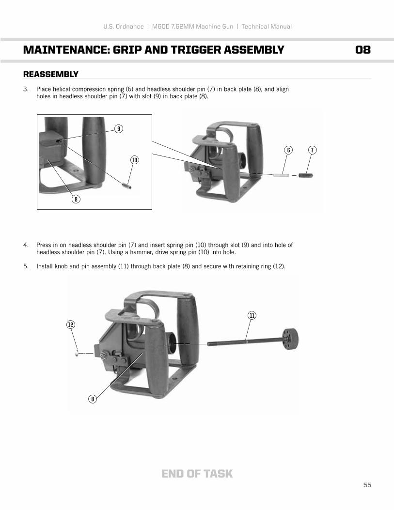
1. Repair by replacing all authorized parts.2. Once repair/replacement is completed, clean and lubricate.3. Repair of subassemblies is covered in the following work packages:
4. Clean rusted or shiny metal surfaces with crocus cloth. Wash thoroughly with dry cleaning solvent.
5. Following manufacturer’s instructions for use, apply solid film lubricant to all external surfaces showing wear and allow weapon to dry 12 hours before being used.
U.S. Ordnance | M60D 7.62MM Machine Gun | Technical Manual
MAINTENANCE: M60D MACHINE GUN 07
WARNINGDry cleaning solvent (SD) is flammable. Do not clean parts near an open flame or in a smoking area. Dry cleaning solvent evaporates quickly and has a drying effect on the skin. When used without protective gloves, solvent may cause irritation to or cracking of the skin.
Using paint thinners, gasoline, kerosene, benzene (benzol), water, steam, or air for cleaning the weapon is prohibited. Use only authorized cleaning materials.
CAUTIONThe buffer assembly will not be submerged in solvents or other cleaning fluids. Using lubricant on a cloth, wipe exterior surfaces to prevent corrosion.
Care MUST be exercised to avoid getting cleaner, lubricant and preservative (CLP/RBC) in the gas cylinder when cleaning the barrel. Position the gas cylinder above the barrel during cleaning. The gas cylinder components will be removed and cleaned only when inspection reveals that the piston will no longer move within the cylinder under its own weight when the barrel is tilted end to end. If gas cylinder components are cleaned, wipe interior of cylinder and piston dry before reassembly. After reassembly, check for movement of gas piston by manually tilting the barrel assembly. Rewire gas cylinder vent plug.
NOTEDo not dilute CLP/RBC. Shake well before using.
CAUTIONIf solid film lubricant comes in contact with any moving or internal part, clean part with dry cleaning solvent.
Barrel assembly Breech bolt assembly Cartridge feed tray assembly Cover assembly Grip and trigger assembly Operating rod assembly Sear and safety housing assembly
12 pg. 68 09 pg. 5614 pg. 8213 pg. 7408 pg. 5210 pg. 6311 pg. 64

49
REPAIR (cont)
6. On component parts which have a hard carbon residue, it may be necessary to use CLP/RBC to begin repair. Depending on the amount of carbon residue, coat parts 2 to 16 hours, brush, wipe dry with wiping rag, and lubricate as necessary.
7. Remove cotter pin and headed grooved pin (2).
8. Grasp sear link and spring assembly (3) and push forward until sear assembly activator (4) just touches sear (5). Hold sear link and spring assembly (3) while you position sear link nut (6) to fit in slot of grip and trigger assembly (7).
9. With sear link nut (6) in slot of grip and trigger assembly (7), sight through the holes to determine the amount of adjustment required to align holes. Pull sear link nut (6) out of slot and adjust by turning sear link nut (6), repeating procedures until holes align.
10. Lift sear link nut (6) out of slot and rotate one-half turn clockwise. Push sear assembly link and spring (3) rearward and insert headed grooved pin (2). There should be a slight gap between sear (5) and sear assembly activator (4). Reinstall cotter pin. Lock sear link nut (6) and sear assembly link and spring (3) with safety wire.
U.S. Ordnance | M60D 7.62MM Machine Gun | Technical Manual
MAINTENANCE: M60D MACHINE GUN 07
NOTEThe following procedures are performed only when a specific repair is required.
5436
26
54
7

50
REASSEMBLY
1. For maintenance on cocking handle guide, carrying handle assembly, and barrel lock, refer to maintenance procedures (07, pg. 42).
2. With new wire rope assembly (1) and new swaging sleeves (2), securely connect quick release pin (3) using the following procedures:
a. Insert one end of wire rope assembly (1) through swaging sleeve (2) and through the opening in base of rear sight (4). Loop wire assembly (1) around the front of rear sight (4) base and insert end back through swaging sleeve (2). Using parallel pliers, crimp swaging sleeve (2) to wire rope assembly (1).
b. Insert other end of wire rope assembly (1) through another swaging sleeve (2) and through ring of quick release pin (3). Loop wire rope assembly (1) around quick release pin (3), and insert the end back through swaging sleeve (2). Using parallel pliers, crimp swaging sleeve (2) to wire rope assembly (1).
U.S. Ordnance | M60D 7.62MM Machine Gun | Technical Manual
MAINTENANCE: M60D MACHINE GUN 07
NOTEThe following procedures are performed only when a specific repair is required.
4
22
1
3

END OF TASK51
REASSEMBLY (cont)
3. Place gun adapter (5) on bottom of receiver assembly (6), align holes, and install spring pin (7). Using hammer, drive in spring pin (7) until flush.
4. Insert quick release pin (3).
U.S. Ordnance | M60D 7.62MM Machine Gun | Technical Manual
MAINTENANCE: M60D MACHINE GUN 07
3
7
5
6

52
U.S. Ordnance | M60D 7.62MM Machine Gun | Technical Manual
MAINTENANCE: GRIP AND TRIGGER ASSEMBLY 08
THIS TASK COVERS: Inspection, Disassembly, Repair, Reassembly
INITIAL SETUP
Maintenance LevelUnit
Tools and Special ToolsEchelon Tool Kit
General Safety Instructions
INSPECTION
1. Inspect general condition of grip and trigger assembly.
2. Inspect for missing, loose, or damaged parts.
3. Inspect for no binding of parts.
DISASSEMBLY
1. Remove retaining ring (1) and slide out knob and pin assembly (2).
Materials/PartsCloth, abrasive (crocus) Dry cleaning solvent (SD) Gloves, rubber Lubricant, solid film
WARNINGBe careful when removing and installing spring-loaded components.Carelessness could cause injury.
2
1

53
U.S. Ordnance | M60D 7.62MM Machine Gun | Technical Manual
MAINTENANCE: GRIP AND TRIGGER ASSEMBLY 08
DISASSEMBLY (cont)
2. Hold down headless shoulder pin (3) and helical compression spring (4) while removing spring pin (5).
3. Remove cotter pins (6) and push out headed grooved pins (7).
4. Raise up grip and trigger assembly (8) and remove helical compression springs (9).
5
6
6
7
9
9
8
4 3

54
REPAIR
1. Repair by replacing all authorized parts.
2. Clean rusted or shiny metal surfaces with crocus cloth. Wash thoroughly with dry cleaning solvent (SD).
3. Following manufacturer’s instructions for use, apply solid film lubricant to all external surfaces showing wear and allow weapon to dry 12 hours before being used.
4. Damage not repaired by minor replacement of parts will cause replacement of entire assembly.
REASSEMBLY
1. Raise up grip blocks (3). and trigger assembly (1) and insert helical compression springs (2) into trigger stop.
2. Align holes in grip and trigger assembly (1), install headed grooved pins (7), and secure with cotter pins (6).
WARNINGDry cleaning solvent (SD) is flammable. Do not clean parts near an open flame or in a smoking area. Dry cleaning solvent evaporates quickly and has a drying effect on the skin. When used without protective gloves, solvent may cause irritation to or cracking of the skin.
CAUTIONIf solid film lubricant comes in contact with any moving or internal part,clean part with dry cleaning solvent.
U.S. Ordnance | M60D 7.62MM Machine Gun | Technical Manual
MAINTENANCE: GRIP AND TRIGGER ASSEMBLY 08
6
6
7
2
2
3
1
7
END OF TASK55
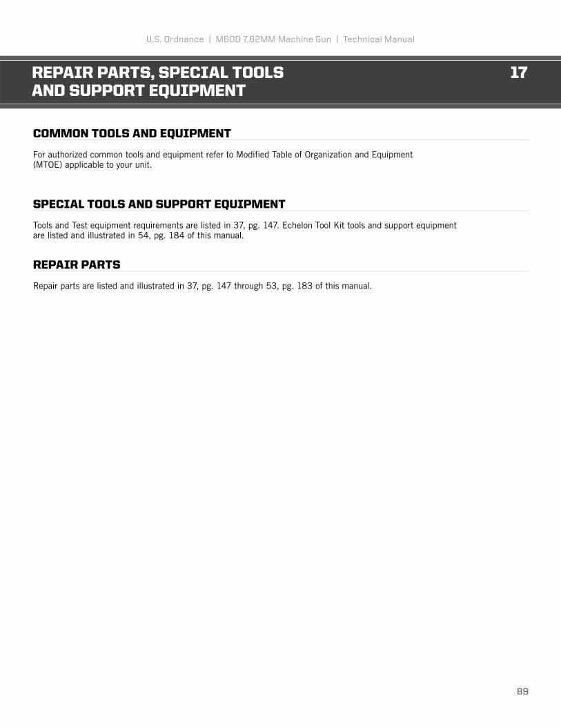
REASSEMBLY
3. Place helical compression spring (6) and headless shoulder pin (7) in back plate (8), and align holes in headless shoulder pin (7) with slot (9) in back plate (8).
4. Press in on headless shoulder pin (7) and insert spring pin (10) through slot (9) and into hole of headless shoulder pin (7). Using a hammer, drive spring pin (10) into hole.
5. Install knob and pin assembly (11) through back plate (8) and secure with retaining ring (12).
U.S. Ordnance | M60D 7.62MM Machine Gun | Technical Manual
MAINTENANCE: GRIP AND TRIGGER ASSEMBLY 08
10
8
9
6 7
11
12
8

56
U.S. Ordnance | M60D 7.62MM Machine Gun | Technical Manual
MAINTENANCE: BREECH BOLT ASSEMBLY 09
THIS TASK COVERS: Inspection, Disassembly, Repair, Reassembly
INITIAL SETUP
Maintenance LevelUnit
Tools and Special ToolsEchelon Tool Kit
General Safety Instructions
Materials/PartsLubricant (as required)
WARNINGBe careful when removing and installing spring-loaded components. Carelessness could cause injury.
The weapon’s breech bolt assembly will be used to check headspace. Do not intermix the breech bolt assembly or barrel and bipod assembly without checking headspace requirements.
CAUTIONDo not allow breech bolt to slam closed when the weapon is empty, as this will cause damage to the locking surfaces on the barrel socket and breech bolt.
NOTEHeadspace will be gauged annually, using appropriate gauges, by direct support maintenance personnel. If space is faulty, a new breech bolt or test bolt gauge is required to determine if the barrel or breech bolt is defective.

57
U.S. Ordnance | M60D 7.62MM Machine Gun | Technical Manual
MAINTENANCE: BREECH BOLT ASSEMBLY 09
INSPECT
1. Inspect back side of breech bolt assembly bottom lug (1) for minor chips, dents, gouges, and burrs. These conditions may be corrected by stoning.
2. Inspect front side of breech bolt assembly bottom lug (1) for sharp edges or burrs.
3. Inspect breech bolt assembly cam area (2) for raised or rough surfaces.
4. Inspect left front corner of breech bolt assembly stripping lug (3). A stripping lug showing complete loss of original radius surface area due to chipping may still be used.
NOTENo cracks are permitted in this area. Notify direct support maintenance if cracks are found.
CAUTIONIf sharp edges or burrs are present, notify direct support maintenance for replacement.
NOTERounding or mutilation found on breech bolt locking surfaces will cause damage to mating locking surfaces on the barrel socket. If breech bolt is rounded or mutilated, notify direct support maintenance.
NOTERaised or rough surfaces can be repaired by stoning. Notify direct support maintenance for replacement if stoning fails.
1
2
3

58
U.S. Ordnance | M60D 7.62MM Machine Gun | Technical Manual
MAINTENANCE: BREECH BOLT ASSEMBLY 09
5. Inspect back side of breech bolt assembly stripping lug (3). Burrs may be smoothed by stoning but cracks, chips, dents, or gouges are not repairable in this area. If cracks, chips, dents, or gouges are present, notify direct support maintenance.
DISASSEMBLY EXTRACTOR
1. Place extractor tool “tooth” (1) onto extractor plunger detent (2).
2. Thread extractor tool (3) until helical spring is full compressed.
3. At this point, extractor is no longer under spring tension and can be removed.
1
3
2
1

59
DISASSEMBLY EXTRACTOR (cont)
4. While controlling (4) extractor plunger and helical spring, release tension on extractor tool (3).
5. Slide extractor plunger (5) and helical spring (6) free from bolt.
DISASSEMBLY EJECTOR
1. Using a punch, hammer ejector spring pin (7) free from breech bolt.
2. Slide ejector helical spring (6) and plunger (5) free from breech bolt.
U.S. Ordnance | M60D 7.62MM Machine Gun | Technical Manual
MAINTENANCE: BREECH BOLT ASSEMBLY 09
3
6
6
5
5
7
4

2
3
60
INSPECT
1. Repair by replacing all authorized components.
2. Repair by stoning burrs and raised surfaces from bottom lug’s (1) forward corner and rear locking surface. No cracks, chips, dents, and gouges are permitted on the rear locking surface.
3. Repair cam area (2) by stoning raised or rough surfaces.
4. Repair camming surface of stripping lug (3) by stoning the forward edge. A stripping lug showing complete loss of original radius surface area may still be used.
U.S. Ordnance | M60D 7.62MM Machine Gun | Technical Manual
MAINTENANCE: BREECH BOLT ASSEMBLY 09
NOTEBurrs or raised surfaces may be removed or smoothed using a fine grit sharpening stone. DO NOT change the tolerances of any component by stoning. Components with cracks, chips, dents, or gouges shall be reported to direct support maintenance for repair or replacement.
Cracks, chips, dents, or gouges on breech bolt locking surfaces and rounding/mutilation of the rear locking surface can damage the mating locking surfaces of the barrel socket. Damage to barrel socket locking surfaces can damage the breech bolt. Notify direct support maintenancefor replacement or repair if either condition exists.
1

2
1
61
5. Repair by stoning burrs or raised surfaces from rear locking surface of stripping lug (4). No cracks, chips, dents, or gouges are permitted in this area.
REASSEMBLY EXTRACTOR
1. Slide extractor replacement tool underneath extractor detent until tooth on tool catches edge inside bolt recess.
2. Place the compression tool (1) into the extractor detent and compress spring (2).
3. Replace extractor.
4. Release spring tension with extractor tool (3).
U.S. Ordnance | M60D 7.62MM Machine Gun | Technical Manual
MAINTENANCE: BREECH BOLT ASSEMBLY 09
3
3

END OF TASK62
REASSEMBLY EJECTOR
1. Slide ejector cartridge (6) and helical spring (5) back into breech bolt.
2. Re-tap spring pin (7) back into its original position.
3. Secure by tapping spring pin (7) until it is flush with body of breech bolt (3).
4. Apply lubricant sparingly to bolt locking lugs (8), actuator roller (9), and camming recess (10).
U.S. Ordnance | M60D 7.62MM Machine Gun | Technical Manual
MAINTENANCE: BREECH BOLT ASSEMBLY 09
9
6
5
7
10
8
8

END OF TASK63
U.S. Ordnance | M60D 7.62MM Machine Gun | Technical Manual
MAINTENANCE: OPERATING ROD ASSEMBLY 10
THIS TASK COVERS: Inspection, Disassembly, Repair, Reassembly
INITIAL SETUP
Maintenance LevelUnit
Tools and Special ToolsEchelon Tool Kit
REPAIR
1. Check for burrs, cracks, distortion, and mutilation on yoke area (1), firing pin bearing area (2), guide ways (3), and sear notches (4).
2. Raised or upset areas are unacceptable on tower area (5), firing pin bearing area (2), and guide ways (3). Remove burrs and sharp edges by stoning.
3. Apply lubricant sparingly on linear-rotating roller (6) and surfaces (7) immediately below the yoke which ride within the receiver assembly rails.
Materials/PartsLubricant (as required)
2
1
6
3
5
4
7

64
U.S. Ordnance | M60D 7.62MM Machine Gun | Technical Manual
MAINTENANCE: SEAR AND 11SAFETY HOUSING ASSEMBLY
THIS TASK COVERS: Inspection, Disassembly, Repair, Reassembly
INITIAL SETUP
Maintenance LevelUnit
Tools and Special ToolsEchelon Tool Kit
Troubleshooting ReferencesRefer to 06, pg. 27
General Safety Instructions
INSPECTION
1. Inspect sear and safety housing assembly for bent, broken, or missing parts.
2. Inspect that small arms safety prevents sear from moving when in safe (S) position but allows sear to move freely when in fire (F) position.
DISASSEMBLY
1. Field-strip weapon.
Materials/PartsCloth, abrasive (crocus) Dry cleaning solvent (SD) Gloves, rubber Lubricant, solid film
WARNINGBe careful when removing and installing spring-loaded components.Carelessness could cause injury.
NOTEThe following procedures are in addition to field-stripping.

2
5
4 2
3
65
U.S. Ordnance | M60D 7.62MM Machine Gun | Technical Manual
MAINTENANCE: SEAR AND 11SAFETY HOUSING ASSEMBLY
DISASSEMBLY (cont)
2. Hold sear and safety housing firmly. Depress safety plunger (2) while removing small arms safety (3). Release pressure on safety plunger (2).
3. Lift out safety plunger (2) and helical compression spring (4) from the sear housing (5).

1
2 3
66
U.S. Ordnance | M60D 7.62MM Machine Gun | Technical Manual
MAINTENANCE: SEAR AND 11SAFETY HOUSING ASSEMBLY
REPAIR
1. Repair by replacing all authorized components.
2. Clean rusted metal surfaces with crocus cloth. Wash thoroughly with dry cleaning solvent.
3. Following manufacturer’s instructions for use, apply solid film lubricant to all external surfaces showing wear and allow weapon to dry 12 hours before being used.
REASSEMBLY
1. Hold sear and safety housing (1) securely in hand.
2. Install helical compression spring (2) and safety plunger (3) into sear housing (1).
WARNINGDry cleaning solvent (SD) is flammable. Do not clean parts near an open flame or in a smoking area. Dry cleaning solvent evaporates quickly and has a drying effect on the skin. When used without protective gloves, solvent may cause irritation to or cracking of the skin.
CAUTIONIf solid film lubricant comes in contact with any moving or internal part, clean part with dry cleaning solvent.

34
END OF TASK67
U.S. Ordnance | M60D 7.62MM Machine Gun | Technical Manual
MAINTENANCE: SEAR AND 11SAFETY HOUSING ASSEMBLY
REASSEMBLY (cont)
3. Press in on safety plunger (3) with scribe while installing small arms safety (4).
4. Reassemble the weapon.

68
U.S. Ordnance | M60D 7.62MM Machine Gun | Technical Manual
MAINTENANCE: BARREL ASSEMBLY 12
THIS TASK COVERS: Inspection, Disassembly, Repair, Reassembly
INITIAL SETUP
Maintenance LevelUnit
Tools and Special ToolsEchelon Tool Kit
Troubleshooting ReferencesRefer to 06, pg. 27
INSPECTION
1. Inspect gas extension for tightness and safety wiring.
2. Inspect general appearance of barrel and carry handle assembly.
Materials/PartsCloth, abrasive (crocus) Dry cleaning solvent (SD) Gloves, rubber Lubricant (as required)Lubricant, solid filmRag, wiping

2
3
69
U.S. Ordnance | M60D 7.62MM Machine Gun | Technical Manual
MAINTENANCE: BARREL ASSEMBLY 12
DISASSEMBLY
1. Using diagonal cutting pliers, cut safety wire (2) and (3), and discard.
2. Using combination wrench, remove lock nut (1) and vent plug (2). Tilt barrel, gas piston (7) should fall out.
2 17

70
REPAIR
1. The use of crocus cloth is restricted for external surfaces only.
2. Following manufacturers instructions for use, apply solid film lubricant to all external surfaces showing wear and allow weapon to dry 12 hours before being used.
3. Repair by replacing safety wire.
WARNINGDry cleaning solvent (SD) is flammable. Do not clean parts near an open flame or in a smoking area. Dry cleaning solvent evaporates quickly and has a drying effect on the skin. When used without protective gloves, solvent may cause irritation to or cracking of the skin.
CAUTIONCare MUST be exercised to avoid getting lubricant or oil in the gas cylinder when cleaning the barrel. Position the gas cylinder above the barrel during cleaning. The gas cylinder components will be removed and cleaned only when inspection reveals that the piston will no longer move within the cylinder under its own weight when the barrel is tilted end for end. If gas cylinder components are cleaned, wipe interior of cylinder and piston dry before reassembly. After reassembly, check for movement of gas piston by manually tilting the barrel assembly. Rewire vent plug.
NOTEDo not dilute lubricant. Shake well before using.
Burrs or raised surfaces may be removed or smoothed using a fine grit sharpening stone. DO NOT change the tolerances of any component by stoning. Cracks, chips, dents, or gouges on components shall be reported to direct support maintenance for repair or replacement.
Cracks, chips, dents, or gouges on breech bolt locking surfaces can damage the barrel socket. Damage to barrel socket locking surfaces can damage the breech bolt. Notify direct support maintenance for replacement or repair if either condition exists.
No abrasive materials will be used to clean the gas piston or the inside of the gas cylinder (i.e. green pads, steel wool or crocus cloth). The receiver brush will not be used to clean inside of gas cylinder.
CAUTIONIf solid film lubricant comes in contact with any moving or internal part,clean part with dry cleaning solvent.
MAINTENANCE: BARREL ASSEMBLY 12
U.S. Ordnance | M60D 7.62MM Machine Gun | Technical Manual

71
REPAIR (cont)
4. Insert reamer (1) all the way in the machine thread plug hole (2) to make sure all carbon is removed from holes in gas cylinder (4) and wipe carbon residue from gas cylinder (4).
5. Remove carbon from gas piston and wipe carbon residue from gas piston.
NOTERestore gas cylinder assembly to a serviceable condition by performing the following procedures.
MAINTENANCE: BARREL ASSEMBLY 12
U.S. Ordnance | M60D 7.62MM Machine Gun | Technical Manual
*NOTE: Cutaway Image.
4
2
1

72
REASSEMBLY
1. Install gas piston (1) in gas cylinder (2).
2. Install and tighten vent plug (3) and then lock nut (4).
MAINTENANCE: BARREL ASSEMBLY 12
U.S. Ordnance | M60D 7.62MM Machine Gun | Technical Manual
4312

END OF TASK73
REASSEMBLY (cont)
3. Tilt barrel (7) up and down. Gas piston should click as it moves inside gas cylinder (2). If click is not heard, disassemble, clean, and assemble again.
4. Secure gas extension assembly shown, using safety wire.
MAINTENANCE: BARREL ASSEMBLY 12
U.S. Ordnance | M60D 7.62MM Machine Gun | Technical Manual
7
2

74
U.S. Ordnance | M60D 7.62MM Machine Gun | Technical Manual
MAINTENANCE: COVER ASSEMBLY 13
THIS TASK COVERS: Inspection, Disassembly, Repair, Reassembly
INITIAL SETUP
Maintenance LevelUnit
Tools and Special ToolsEchelon Tool Kit
Troubleshooting ReferencesRefer to 06. pg. 27
General Safety Instructions
INSPECTION
1. Inspect cover assembly for broken, bent, worn, or missing parts.
2. Inspect cover assembly for proper cleaning and lubrication.
4. Visually inspect external surfaces for dull black finish.
DISASSEMBLY
1. Remove guide cotter pin (1) and straight shaft (2).
Materials/PartsBrush, cleaning, tool and partsDry cleaning solvent (SD) Gloves, rubberLacquerLubricant (as required)Rag, wiping
WARNINGDry cleaning solvent (SD) is flammable. Do not clean parts near an open flame or in a smoking area. Dry cleaning solvent evaporates quickly and has drying effect on the skin. When used without protective gloves, solvent may cause irritation to or cracking of the skin.
1
2

75
U.S. Ordnance | M60D 7.62MM Machine Gun | Technical Manual
MAINTENANCE: COVER ASSEMBLY 13
2. Push down and over to remove front (3) and rear (4) cartridge guides.
3. Pull back on feed cam retainer (5) with punch and lift out feed cam assembly (6).
4. Press in on spring lever clip (7) and lift out feed lever assembly (8).
5. Lift out helical torsion spring (9).
3
6
8
97
5
4

76
6. Slide feed pawl assembly (10) in slot (11) and guide it toward feed lever stud (12). Remove feed pawl assembly (10).
REPAIR
1. Replace damaged helical torsion spring (1).
2. Clean powder-fouled parts with CLP/Break Free/RBC and a brush. Wipe all parts clean and remove excess CLP/RBC with a wiping rag.
3. Apply a coating of lubricant on the lower surfaces and frame mating areas of feed pawl assembly (2).
4. Dampen wiping rag with lubricant and wipe each part before reassembling cover assembly (3).
U.S. Ordnance | M60D 7.62MM Machine Gun | Technical Manual
MAINTENANCE: COVER ASSEMBLY 13
1
2
3
12
11
10

77
REPAIR (cont)
5. Refinish exterior of all aluminum parts not having a dull black finish by painting with a black lusterless lacquer.
6. Clean worn or flaking surfaces with crocus cloth. Wash thoroughly with dry cleaning solvent.
7. Following manufacturer’s instructions for use, apply lacquer to all external aluminum surfaces showing wear and allow to dry for appropriate length of time before being used.
REASSEMBLY
1. Place feed pawl assembly (1) in slot (2) near feed lever stud (3) and slide it into narrow leg of slot (2).
2. Place helical torsion spring (4) around feed lever stud (3) and hook one end of helical torsion spring in slot (2).
U.S. Ordnance | M60D 7.62MM Machine Gun | Technical Manual
MAINTENANCE: COVER ASSEMBLY 13
4
1
3 2
3
2

78
3. Position feed lever assembly (5) so slot (6) is aligned above projection (7) on feed pawl assembly (1).
4. Press spring lever clip (8) in feed lever assembly (5) and place on feed lever stud (3). Make sure helical torsion spring (4) rests against side of feed lever assembly (5).
5. Align feed cam assembly (9) with feed lever assembly (5) so cam stud (10) enters slot in the end of feed lever assembly (5). Align hole (11) over cover stud (12).
U.S. Ordnance | M60D 7.62MM Machine Gun | Technical Manual
MAINTENANCE: COVER ASSEMBLY 13
11
5
8
1
7
65
9
1012
5
4
3

79
REASSEMBLY (cont)
6. Pull back on feed cam retainer (13) with punch and press down on feed cam assembly (9) to latch it.
7. Move feed pawl assembly (1) back and forth several times to check it for freedom of movement. Make sure feed pawl assembly (1) does not bind. If binding is present, notify direct support maintenance.
8. Install front (14) and rear (15) cartridge guides. Secure with straight shaft (16).
U.S. Ordnance | M60D 7.62MM Machine Gun | Technical Manual
MAINTENANCE: COVER ASSEMBLY 13
13
9
1
15
1614

END OF TASK80
REASSEMBLY (cont)
9. Install guide cotter pin (17) bend prongs of guide retaining pin around straight shaft so ends do not stick out.
U.S. Ordnance | M60D 7.62MM Machine Gun | Technical Manual
MAINTENANCE: COVER ASSEMBLY 13
17

81
U.S . ORDN A NCE
M60DPROVEN UNDER FIRE

MAINTENANCE: CARTRIDGE FEED 14TRAY ASSEMBLY
82
U.S. Ordnance | M60D 7.62MM Machine Gun | Technical Manual
THIS TASK COVERS: Disassembly, Repair, Reassembly
INITIAL SETUP
Maintenance LevelUnit
DISASSEMBLY
1. Slowly tap cartridge shaft (1) part way out with a hammer and 3/32-inch drive pin punch and remove one yoke roller (2), helical torsion spring (3), and cartridge retainer pawl (4) from underside of cartridge tray frame assembly (5).
2. Remove cartridge shaft (1) and separate second yoke roller (2) from cartridge tray frame assembly (5).
REPAIR
Repair by replacing all authorized components.
Tools and Special ToolsEchelon Tool Kit
5
14
3
2

MAINTENANCE: CARTRIDGE FEED 14TRAY ASSEMBLY
83
U.S. Ordnance | M60D 7.62MM Machine Gun | Technical Manual
REASSEMBLY
1. Attach one yoke roller (1) to cartridge tray frame assembly (2) and insert cartridge shaft (3) in part way.
2. Insert cartridge retainer pawl (4) and helical torsion spring (5) as a unit from underside of cartridge tray frame assembly (2) and align helical torsion spring (5) with cartridge shaft (3).
3. Insert second yoke roller (6) in cartridge tray frame assembly (2). Insert 3/32-inch drive pin punch in other side and work it through cartridge retainer pawl (4) and helical torsion spring (5) to help keep all parts in line.
1
3
3
5
4
2
2
2
6
4

MAINTENANCE: CARTRIDGE FEED 14TRAY ASSEMBLY
END OF TASK84
U.S. Ordnance | M60D 7.62MM Machine Gun | Technical Manual
REASSEMBLY (cont)
4. Use hammer to tap cartridge shaft (3) and drive it through retainer pawl (4), helical torsion spring (5) until it drives out drive pin punch. Flush both ends of the cartridge shaft (3).
4
3
5

85
U.S . ORDN A NCE
M60DPROVEN UNDER FIRE

86
U.S. Ordnance | M60D 7.62MM Machine Gun | Technical Manual
LUBRICATION INSTRUCTIONS 15
Weapons NOT in use or that are to be stored in the arms room for prolonged periods should have allinterior and exterior metal parts lubricated and a light film of lubricant applied to the interior of the gascylinder and the gas piston following cleaning and inspection.
The use of lubricant will not eliminate periodic cleaning and/or inspection to ensure that corrosion is not forming. Remove excess lubricant from the remainder of the weapon. Avoid lubricant contact with non-metallic surfaces.

87
U.S. Ordnance | M60D 7.62MM Machine Gun | Technical Manual
PREPARATION FOR STORAGE OR SHIPMENT 16
ADMINISTRATIVE STORAGE
Refer to Chapter 3, 36 (pg. 145).
Manufacturer recommends use of a dry, temperature controlled storage area for long-term storage. Machine guns should be packaged in protective cases to prevent any damage to due to falls.
Weapons placed in long-term storage should be inspected every 90 days. Weapons must be inspected for any visual indicators of corrosion.
Before being placed into storage, machine guns must be clean, dry, and lubricated with a light coat of CLP/Break Free.

88
CHAPTER 3 | DIRECT SUPPORTMAINTENANCE INSTRUCTIONS
89
U.S. Ordnance | M60D 7.62MM Machine Gun | Technical Manual
REPAIR PARTS, SPECIAL TOOLS 17AND SUPPORT EQUIPMENT
COMMON TOOLS AND EQUIPMENT
For authorized common tools and equipment refer to Modified Table of Organization and Equipment(MTOE) applicable to your unit.
SPECIAL TOOLS AND SUPPORT EQUIPMENT
Tools and Test equipment requirements are listed in 37, pg. 147. Echelon Tool Kit tools and support equipmentare listed and illustrated in 54, pg. 184 of this manual.
REPAIR PARTS
Repair parts are listed and illustrated in 37, pg. 147 through 53, pg. 183 of this manual.

90
U.S. Ordnance | M60D 7.62MM Machine Gun | Technical Manual
TROUBLESHOOTING 18
TROUBLESHOOTING PROCEDURES
Refer to work package 06, pg. 27 of this manual.

91
U.S. Ordnance | M60D 7.62MM Machine Gun | Technical Manual
MAINTENANCE PROCEDURES 19
GENERAL
Without a gauge, or inspection criteria, to determine if any component part or assembly of a weapon hasexcessive wear and/or how deep of a crescent/half-moon appearance make the component/assemblyunserviceable, the determining factors will have to remain as follows:
a. The functional/operational check with dummy cartridges. b. The experience and judgmental expertise of the DS armorer and/or maintenance personnel to determine that a component, assembly or repair part needs replacement.
NOTEWhen a weapon is received by direct support with a maintenance request, all gauging requirements must be checked as a standard maintenance procedure. In addition, the weapon must be inspected and any other deficiencies found will be repaired, or noted for repair, at the appropriate maintenance level. As a minimum requirement, for active duty M60D guns the headspace and gauging must be verified annually by direct support personnel. If the M60D machine gun has to go to direct support maintenance for any repair, both barrel assemblies must be turned in with the weapon.
Burrs or raised surfaces may be removed or smoothed using a fine grit sharpening stone. DO NOT change the dimensions of any components by stoning. Cracks, chips, dents, or gouges on components shall be reported to the appropriate maintenance level for repair or replacement.
Cracks, chips, dents, or gouges on breech bolt locking surfaces can damage the barrel socket. Damage to barrel socket locking surfaces can damage the breech bolt.

92
U.S. Ordnance | M60D 7.62MM Machine Gun | Technical Manual
MAINTENANCE: M60D MACHINE GUN 20 SECTION 1 of 2
THIS TASK COVERS: Disassembly, Repair, Test/Inspection, Reassembly
INITIAL SETUP
Maintenance LevelDirect Support
Tools and Special ToolsCombination square (GGG-S-656)or equivalent)Dial indicating scale (AAA-S-133)or equivalent)Firing pin protrusion gauge (7274754)Headspace gauge (7274790)Machinist’s steel rule (GGG-R-791or equivalent)Plain cylindrical plug gauge (7458598)Small Arms Gauge Kit MS (5910297)Echelon Tool KitTest bolt gauge (7799699)
General Safety Instructions
DISASSEMBLY
1. Field-strip weapon.
Materials/PartsIdentification tagLacquer Wire, Nonelectrical (MS20995C32)
Troubleshooting ReferencesRefer to 06, pg. 27
CAUTIONThe ability to detect oil movement on or around the rivet head and/or between riveted components does not classify rivets as being loose, and is an unauthorized procedure.
NOTEThe disassembly/reassembly procedures in this paragraph are additions to those described in organizational maintenance (07, pg. 42).
Before doing the trigger pull test for M60D, the weapons must be reassembled.
No stamping or etching is authorized. Use tags for identification.
WARNINGMake sure weapon is cleared and that there are no obstructions in the barrel.

93
U.S. Ordnance | M60D 7.62MM Machine Gun | Technical Manual
MAINTENANCE: M60D MACHINE GUN 20
DISASSEMBLY (cont)
2. Remove rear sight (1) from receiver assembly (2).
REPAIR
1. Repair by replacing all authorized components.
2. Additional maintenance procedures for subassemblies are contained in the followin work packages:
TEST/INSPECTION
LOOSE RECEIVER TEST
1. a. Check for loose receiver. Remove all major assemblies and internal components.
WARNINGMake sure weapon is cleared and that there are no obstructions in the barrel.
Barrel and carrying handle assembly Breech bolt assembly Cocking handle assembly Cover assembly Operating rod assembly Gun receiver assembly
12 pg. 68 09 pg. 56 33 pg. 13913 pg. 7410 pg. 6334 pg. 140
1
2

94
TEST/INSPECTION (cont)
LOOSE RECEIVER TEST (cont)
b. Clamp receiver assembly (1) securely in machinist’s vise equipped with jaw caps.
2. Place combination square (2) against receiver assembly (1). Combination square (2) should be parallel to receiver assembly (1) with the edge of its blade touching the side of receiver assembly (1).
3. Attach dial indicating scale (3) to rear of receiver assembly (1).
4. Pull dial indicating scale (3) to 10 pounds of pressure and allow combination square (2) to move with receiver assembly (1).
WARNINGIn the following step, after obtaining 10 pounds of pressure on dial indicating scale, release pressure and do not move combination square.
U.S. Ordnance | M60D 7.62MM Machine Gun | Technical Manual
MAINTENANCE: M60D MACHINE GUN 20
1
3
2
1

95
TEST/INSPECTION (cont)
LOOSE RECEIVER TEST (cont)
5. Attach dial indicating scale (3) on other side of receiver assembly (1) and pull to 10 pounds of pressure. Butt machinist’s steel rule (4) against receiver assembly (1) while holding pressure.
6. Read distance between receiver assembly (1) and blade of combination square (2). Total horizontal movement should not exceed 3/32 (0.094) of an inch.
7. Remove dial indicating scale (3).
8. Move combination square (2) against receiver assembly (1), and attach dial indicating scale (3) to bottom of receiver assembly (1).
U.S. Ordnance | M60D 7.62MM Machine Gun | Technical Manual
MAINTENANCE: M60D MACHINE GUN 20
4
23
1
3
2
1

96
TEST/INSPECTION (cont)
LOOSE RECEIVER TEST (cont)
9. Mark receiver assembly (1) at whole number increments for reference point.
10. Pull dial indicating scale (3) to 10 pounds of pressure and hold it. Mark a line on the blade of combination square (2), or on the rear of receiver assembly (1), with pencil.
11. Remove dial indicating scale (3).
12. Attach dial indicating scale (3) to upper side of receiver assembly (1), pull dial indicating scale (3) to 10 pounds of pressure, and hold it.
13. Measure vertical movement by using scribe line as a reference and reading against combination square (2). Total vertical movement should not exceed 3/32 (0.094) of an inch.
14. Remove dial indicating scale (3) from receiver assembly (1).
U.S. Ordnance | M60D 7.62MM Machine Gun | Technical Manual
MAINTENANCE: M60D MACHINE GUN 20
2
2
3
1
1
3

97
TEST/INSPECTION (cont)
LOOSE RECEIVER TEST (cont)
15. Inspect receiver assembly (1) and weld areas (5, 6, and 7). Minute or full length cracks in welds are considered serviceable providing they pass the looseness check of 3/32 (0.094) of an inch, Cracks in the base metal of the receiver assembly (1) are a reason to consider it unserviceable.
16. Raise barrel muzzle up to about 30 to 45 degree angle so locking surface can be seen clearly.
17. Moderate to severe mutilation or chipping on either surface shall be cause for removing barrel from service.
NOTEReceiver assemblies exceeding the maximum looseness tolerance of 3/32 (0.094) of an inch vertically or horizontally will be judged unserviceable. Receiver assemblies having tolerances of less than 3/32 (0.094) of an inch in either direction will be judged serviceable.
U.S. Ordnance | M60D 7.62MM Machine Gun | Technical Manual
MAINTENANCE: M60D MACHINE GUN 20
5
1
1
7
6
1

98
TEST/INSPECTION (cont)
LOOSE RECEIVER TEST (cont)
18. Lower barrel muzzle to about 30 to 45 degree angle so cam curved surfaces can be seen clearly.
19. Raised burr on cam cover shall be removed with a smooth half round file and crocus cloth.
20. Return back to service if headspace check is within tolerance.
BREECH BOLT TEST
1. Disassemble bolt assembly.
2. Using a firing pin protrusion gauge and plain cylindrical plug gauge test breech bolt assembly.
3. Push forward firing pin (8) and measure the exposed length with firing pin protrusion gauge (9). Firing pin (8) should protrude a minimum of 0.035 inches to a maximum of 0.043 inches.
4. Push firing pin (8) rearward using plain cylindrical plug gauge (10). The gauge shall not enter the firing pin hole. The body of breech bolt assembly (11) will be replaced if the hole is oversized.
U.S. Ordnance | M60D 7.62MM Machine Gun | Technical Manual
MAINTENANCE: M60D MACHINE GUN 20
8
8
9
10
11

99
TEST/lNSPECTlON (cont)
BREECH BOLT TEST (cont)
5. Check breech bolt assembly and barrel for proper headspace using a headspace gauge, a test bolt gauge, or a new breech bolt assembly.
6. Insert headspace gauge (12) in chamber of barrel assembly (13).
NOTEThe breech bolt assembly used with the weapon will be the only one used when checking headspace. New breech bolt assemblies or test bolt gauges will not be used as a standard.
Do not intermix breech bolt assembly or barrel assembly without checking headspace requirements.
NOTEIf headspace is faulty, a test bolt gauge is required to determine if the barrel or breech bolt is defective. Use of a new breech bolt assembly is authorized only in a contingency situation, where it becomes imperative for deployment of the weapon or to put the weapon on-line, until a test bolt gauge is available.
For annually verified headspace, both barrels (issue and spare) will be checked.
NOTELeading edge of breech bolt assembly locking lugs must not touch the locking recess edge of barrel socket when rotated.
If breech bolt assembly locks in chamber of barrel assembly with headspace gauge installed, headspace is incorrect. The following procedures can be used to determine fault.
U.S. Ordnance | M60D 7.62MM Machine Gun | Technical Manual
MAINTENANCE: M60D MACHINE GUN 20
12
13

100
TEST/lNSPECTlON (cont)
BREECH BOLT TEST (cont)
7. Insert breech bolt assembly (11) in socket of barrel assembly (13), and turn breech bolt assembly (11) with light finger pressure. Breech bolt assembly (11) should not close.
8. Remove breech bolt assembly from socket of barrel assembly (13), and insert test bolt gauge (14) in chamber.
9. If test bolt gauge (14) does not close, breech bolt assembly (11) is defective. If test bolt gauge closes, barrel assembly (13) is defective.
10. Remove test bolt gauge (14) and headspace gauge (12) from barrel assembly (13).
NOTEA new breech bolt assembly may be used if test bolt gauge is not available.
U.S. Ordnance | M60D 7.62MM Machine Gun | Technical Manual
MAINTENANCE: M60D MACHINE GUN 20
14
13
12
131211

101
REASSEMBLY
1. Install and center rear sight (1) in grooved space on receiver assembly (2).
2. Locate original stake marks (3) on receiver assembly (2) used to secure rear sight (1).
3. Stake new stake marks (4) in four different locations.
U.S. Ordnance | M60D 7.62MM Machine Gun | Technical Manual
MAINTENANCE: M60D MACHINE GUN 20
1
43
3 4
2

102
U.S. Ordnance | M60D 7.62MM Machine Gun | Technical Manual
MAINTENANCE OF M60D MACHINE GUN 21 SECTION 2 of 2
THIS TASK COVERS: Disassembly, Repair, Test/Inspection, Reassembly
INITIAL SETUP
Maintenance LevelDepot level maintenance
Tools and Special ToolsAnvil assemblyCombination square (GGG-S-656or equivalent)Dial indicating scale (AAA-S-133)or equivalent)Firing pin protrusion gauge (7274754)Headspace gauge (7274790)
General Safety Instructions
DISASSEMBLY
1. Remove cotter pin (1), headed straight pin (2), lock-release lever (3), and helical compression spring (4).
Tools and Special Tools (cont) Machinist’s steel rule (GGG-R-791)or equivalent)Plain cylindrical plug gauge (7458598)Small Arms Gauge Kit M8 (5910297)Echelon Tool KitTest bolt gauge (7799699)
Materials/PartsLubricant (as required)
CAUTIONDo not allow breech bolt to slam closed when the weapon is empty, as this will cause damage to the locking surfaces on the barrel socket and breech bolt.
NOTEThe disassembly/reassembly procedures in this paragraph are in addition to those described in organizational maintenance (07, pg. 42).
Before doing the trigger pull test for both M60D the weapon must be reassembled.
1
2
3 4

103
U.S. Ordnance | M60D 7.62MM Machine Gun | Technical Manual
MAINTENANCE: M60D MACHINE GUN 21
DISASSEMBLY (cont)
2. Remove cotter pin (5), headed straight pin (6), pawl (7), and helical compression spring (8).
3. Remove solid rivets (9) from magazine bracket (10) only if replacement is necessary.
4. Using 1/2-inch brass punch and hammer, drive rear sight (11) out of grooved area on receiver assembly (12).
NOTEDo not remove rear sight unless rear sight base is damaged.
5
7
8
6
10
99
11
12

MAINTENANCE: M60D MACHINE GUN 21
104
U.S. Ordnance | M60D 7.62MM Machine Gun | Technical Manual
REPAIR
Repair by replacing all authorized components.
Additional maintenance procedures for subassemblies are contained in the following work packages:
REASSEMBLY
1. Insert solid rivets (1) in magazine bracket (2) and through receiver assembly (3).
2. Insert fabricated anvil assembly (4) in receiver assembly (3) by placing grooved plate (5) in left side rails of receiver assembly (3). Once anvil assembly (4) is properly fitted in receiver assembly (3), push smooth surfaced plate (6) in receiver assembly (3).
Barrel and carrying handle assembly Breech bolt assembly Cocking handle assembly Cover assembly Gun receiver assembly Operating rod assembly Rear sight
12 pg. 68 22 pg. 110 33 pg. 13913 pg. 7434 pg. 14010 pg. 6332 pg. 137
3
1
12
4
5 3
6

MAINTENANCE: M60D MACHINE GUN 21
105
U.S. Ordnance | M60D 7.62MM Machine Gun | Technical Manual
REASSEMBLY (cont)
3. Insert and secure back plate (7) in machinist’s vise equipped with jaw caps.
4. Position receiver assembly (3) atop back plate (7). Using a drive pin punch and hammer, tighten solid rivets (1). Pull out smooth surfaced plate (6) and remove anvil assembly (4).
5. Position helical compression spring (8) and pawl (9) in magazine bracket (2). Insert headed straight pin (10) and secure with cotter pin (11).
7
43
7
1
11
2
10
8
9

MAINTENANCE: M60D MACHINE GUN 21
106
REASSEMBLY (cont)
6. Position helical compression spring (12) and lock-release lever (13) in magazine bracket (2). Insert headed straight pin (14) and secure with cotter pin (15).
7. Install and center rear sight (16) in grooved space on receiver assembly (3).
8. Look for old stake marks (17) and restake new stake marks (18) in a different location. Using a center punch and hammer, stake receiver assembly to base of rear sight (16) in four places.
U.S. Ordnance | M60D 7.62MM Machine Gun | Technical Manual
14
2
12
13
15
16
3
1817
17 18

MAINTENANCE: M60D MACHINE GUN 21
107
TRIGGER PULL TEST
1. Check trigger pull using two trigger pull fixtures and a dummy round.
2. Press in on “F’ to place small arms safety (1) in fire (F) position.
3. Pull cocking handle assembly (2) to the rear, and then push it forward.
4. Press in on “S” to place small arms safety (1) in safe (S) position.
5. Load dummy rounds on cartridge feed tray.
NOTEThe weapon must be reassembled before doing trigger pull test.
U.S. Ordnance | M60D 7.62MM Machine Gun | Technical Manual
2
1

MAINTENANCE: M60D MACHINE GUN 21
END OF TASK108
TRIGGER PULL TEST (cont)
6. Attach one trigger pull fixture (3) to each of the triggers (4). position. Place small arms safety (1) in fire (F).
7. Tilt the weapon about 35 to 40 degrees and carefully add weights (5) until sear releases breech bolt assembly. The sear should not release with less than 10 pounds of weight, but should release with less than 20 pounds of weight.
8. Remove weights (5), trigger pull fixtures (3), and the dummy rounds.
U.S. Ordnance | M60D 7.62MM Machine Gun | Technical Manual
1
4
3
3
5
5
3
3

109
U.S . ORDN A NCE
M60DPROVEN UNDER FIRE

110
U.S. Ordnance | M60D 7.62MM Machine Gun | Technical Manual
MAINTENANCE: BREECH BOLT ASSEMBLY 22
THIS TASK COVERS: Repair, Test
INITIAL SETUP
Maintenance LevelDirect Support
Tools and Special ToolsFiring pin protrusion gauge (7274754)Plain cylindrical plug gauge (7458598)Echelon Tool Kit
General Safety Instructions
REPAIR
Repair by replacing all authorized components or by stoning (see 09, pg. 56).
WARNINGThe breech bolt assembly used in the weapon will be the only one used to check the headspace.
Do not intermix the breech bolt assembly or barrel assembly without checking headspace requirements.
CAUTIONDo not allow breech bolt to slam closed when the weapon is empty, as this will cause damage to the locking surfaces or the barrel socket and breech bolt.
NOTEIf headspace is faulty, a new breech bolt or test bolt gauge is required to determine whether the barrel or breech bolt is defective.
WARNINGBurrs or raised surfaces may be removed or smoothed using a fine grit sharpening stone. DO NOT change the dimensions of any components by stoning. Cracks, chips, dents, or gouges on components shall be reported to the appropriate maintenance level for repair or replacement.
Cracks, chips, dents, or gouges on breech bolt locking surfaces can damage the barrel socket. Damage to barrel socket locking surfaces can damage the breech bolt.

END OF TASK111
U.S. Ordnance | M60D 7.62MM Machine Gun | Technical Manual
MAINTENANCE: BREECH BOLT ASSEMBLY 22
TEST
Perform BREECH BOLT TEST (see 23, pg. 139).
NOTESmall arms gauges will be inspected and certified annually. The gauges will not be used unless they are accompanied with the appropriate gauge record.

END OF TASK112
U.S. Ordnance | M60D 7.62MM Machine Gun | Technical Manual
MAINTENANCE: OPERATING ROD ASSEMBLY 23
THIS TASK COVERS: Disassembly, Repair, Reassembly
INITIAL SETUP
Maintenance LevelDirect Support
Tools and Special ToolsEchelon Tool Kit
DISASSEMBLY
Remove spring pin (1), headless straight pin (2), and yoke roller (3) from operating rod assembly (4).
REPAIR
Repair by replacing all authorized components.
REASSEMBLY
Insert yoke roller (3) in slot of operating rod (4). Insert headless straight pin (2) and spring pin (1).
NOTEDisassembly, reassembly, and stoning procedures are covered in 09, pg. 56.
3
4
2
1

113
U.S . ORDN A NCE
M60DPROVEN UNDER FIRE

114
U.S. Ordnance | M60D 7.62MM Machine Gun | Technical Manual
THIS TASK COVERS: Disassembly, Repair, Reassembly
INITIAL SETUP
Maintenance LevelDirect Support
Tools and Special ToolsHeadspace gauge (7274790)Small Arms Gauge Kit M8 (5910297)Echelon Tool KitTest bolt gauge (7799699)
DISASSEMBLY
1. Turn barrel (1) upside down, and place it in a machinist’s vise equipped with vise jaw caps. Tighten vise just enough to hold barrel securely.
Materials/PartsCloth, abrasive (crocus) Dry cleaning solventGloves, rubber)Lubricant (as required)Lubricant, solid filmRag, wiping
Troubleshooting ReferencesRefer to 06, pg. 27
MAINTENANCE: BARREL 24
WARNINGThe breech bolt assembly used in the weapon will be the only one usedto check headspace.
Do not intermix the breech bolt assembly or barrel assembly without checking headspace requirements.
NOTEHeadspace will be gauged annually using appropriate gauges.
If headspace is faulty, a new breech bolt or test bolt gauge is required todetermine whether the barrel or breech bolt is defective.

115
U.S. Ordnance | M60D 7.62MM Machine Gun | Technical Manual
MAINTENANCE: BARREL 24
DISASSEMBLY (cont)
2. Using a portable electric drill and 7/64-inch twist drill, drill off stake marks from both sides of flash suppressor (2).
3. Using a drive pin punch, drive out headless straight pin (3) and discard.
4. Unscrew and remove flash suppressor (2) from barrel (4). Remove barrel (4) from machinist’s vise.
2
3
2
4

116
U.S. Ordnance | M60D 7.62MM Machine Gun | Technical Manual
MAINTENANCE: BARREL 24
REPAIR
1. Repair by replacing all authorized components.
2. The use of crocus cloth is restricted to external surfaces only.
3. Following manufacturer’s instructions for use, apply solid film lubricant to all external surfaces showing wear and allow weapon to dry 12 hours before being used.
4. Clean and lubricate.
5. Additional maintenance procedures for subassemblies of the barrel assembly are listed in the following work packages:
Maintenance: BipodMaintenance: Bipod Leg
25 pg. 12026 pg. 124
WARNINGDry cleaning solvent (SD) is flammable. Do not clean parts near an open flame or in a smoking area. Dry cleaning solvent evaporates quickly and has a drying effect on the skin. When used without protective gloves, solvent may cause irritation to or cracking of the skin.
NOTENo abrasive materials will be used to clean the gas piston or the inside of the gas cylinder (i.e., green pads, steel wool, or crocus cloth). The receiver brush will not be used to clean inside of gas cylinder.

117
U.S. Ordnance | M60D 7.62MM Machine Gun | Technical Manual
MAINTENANCE: BARREL 24
REASSEMBLY
1. Screw flash suppressor (1) on end of barrel (2). Tighten and position flash suppressor (1) so one prong will align with gas cylinder.
2. Clamp barrel (2) in a machinist’s vise equipped with vise jaw caps. Using flash suppressor (3) as a guide, drill #31 drill (0.120) for the new headless straight pin.
NOTEWhen a new flash suppressor or barrel is used, it must be drilled for a headless straight pin. Re-drilling may be required on originally installed equipment if tolerances changed.
1
2
3
2
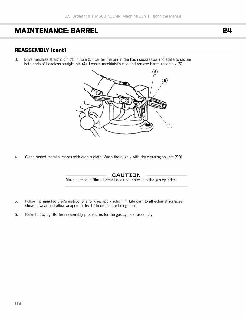
118
U.S. Ordnance | M60D 7.62MM Machine Gun | Technical Manual
MAINTENANCE: BARREL 24
REASSEMBLY (cont)
3. Drive headless straight pin (4) in hole (5), center the pin in the flash suppressor and stake to secure both ends of headless straight pin (4). Loosen machinist’s vise and remove barrel assembly (6).
4. Clean rusted metal surfaces with crocus cloth. Wash thoroughly with dry cleaning solvent (SD).
5. Following manufacturer’s instructions for use, apply solid film lubricant to all external surfaces showing wear and allow weapon to dry 12 hours before being used.
6. Refer to 15, pg. 86 for reassembly procedures for the gas cylinder assembly.
CAUTIONMake sure solid film lubricant does not enter into the gas cylinder.
5
4
6

END OF TASK119
U.S. Ordnance | M60D 7.62MM Machine Gun | Technical Manual
MAINTENANCE: BARREL 24
TEST
1. Visually check the barrel extension locking surfaces for cracks.
WARNINGThe breech bolt assembly used in the weapon will be the only one used to check headspace.
Do not intermix the breech bolt assembly or barrel and barrel assembly without checking headspace requirements.
NOTEHeadspace will be gauged annually using appropriate gauges.
If headspace is faulty, a new breech bolt or test bolt gauge is required to determine whether the barrel or breech bolt is defective.
The test procedure below is in addition to those performed in BARREL TEST (see 20, pg. 92).
NOTEIf barrel is replaced, remove ID tag, and attach to new barrel.

120
U.S. Ordnance | M60D 7.62MM Machine Gun | Technical Manual
THIS TASK COVERS: Disassembly, Repair, Reassembly
INITIAL SETUP
Maintenance LevelDirect Support
Tools and Special ToolsEchelon Tool Kit
DISASSEMBLY
1. Using a standard screwdriver (1) unscrew pivot leg screw (2) and separate bipod leg assembly (3) from bipod pivot assembly (4).
2. Slide screwdriver (1) between pivot leg screw (2) and leg spring plunger (4) and push pivot leg screw free.
Materials/PartsLubricant, solid film
MAINTENANCE: BIPOD 25
NOTEThe following procedures are performed when disassembling and reassembling both bipod legs.
1
1
2
2
4
3
4

121
U.S. Ordnance | M60D 7.62MM Machine Gun | Technical Manual
MAINTENANCE: BIPOD 25
REASSEMBLY (cont)
3. Separate bipod leg (1) from bipod assembly pivot (3) pivot leg screw (2).
4. Remove leg spring plunger (4) and helical compression spring (6) from bipod leg (1).
REASSEMBLY (cont)
1. Repair by replacing all authorized components.
2. Clean rusted metal surfaces with crocus cloth. Wash thoroughly with dry cleaning solvent (SD).
3. Following manufacturer’s instructions for use, apply solid film lubricant to all external surfaces showing wear and allow weapon to dry 12 hours before being used.
WARNINGDry cleaning solvent (SD) is flammable. Do not clean parts near an open flame or in a smoking area. Dry cleaning solvent evaporates quickly and has a drying effect on the skin. When used without protective gloves, solvent may cause irritation to or cracking of the skin.
1
2
3
1
4 6

3
1 2
122
U.S. Ordnance | M60D 7.62MM Machine Gun | Technical Manual
MAINTENANCE: BIPOD 25
REASSEMBLY (cont)
1. Insert headed straight pin (1) and helical compression spring (2) in bipod leg (3).
2. Use standard screwdriver to compress leg spring plunger and helical spring while sliding pivot leg screw (6) back into position.
3. Position bipod leg (3) against bipod pivot assembly pivot (7) and tighten pivot leg screw (6).
6
3
7
6

END OF TASK123
U.S. Ordnance | M60D 7.62MM Machine Gun | Technical Manual
MAINTENANCE: BIPOD 25
REASSEMBLY (cont)
4. Using a hammer and punch, stake pivot leg screw (6) in two places.
6

END OF TASK124
U.S. Ordnance | M60D 7.62MM Machine Gun | Technical Manual
MAINTENANCE: BIPOD LEGS 26
THIS TASK COVERS: Disassembly, Repair, Reassembly
INITIAL SETUP
Maintenance LevelDirect Support
Tools and Special ToolsEchelon Tool Kit
DISASSEMBLY
1. Slide inner (1) and outer (2) leg assemblies until inside and outside holes line up.
2. Use punch to remove dowel pin (3) from inner and outer leg assemblies.
3. Slide inner and outer leg assemblies free.
REPAIR
Replace parts as needed. Reassemble.
REASSEMBLY
1. Slide inner and outer leg assemblies together.
2. Slide inner and outer leg assemblies until inside and outside holes line up.
3. Replace dowel pin.
NOTEIf foot of bipod leg rotates replace the entire leg assembly.
32
1

END OF TASK125
U.S. Ordnance | M60D 7.62MM Machine Gun | Technical Manual
MAINTENANCE: COVER ASSEMBLY 27
THIS TASK COVERS: Disassembly, Repair, Reassembly
INITIAL SETUP
Maintenance LevelDirect Support
Tools and Special ToolsEchelon Tool Kit
DISASSEMBLY
Refer to 16, pg. 87 for disassembly of cover assembly.
REPAIR
1. Repair by replacing all authorized components.
2. Additional maintenance procedures for subassemblies of the cover assembly are contained in the following work packages:
REASSEMBLY
Refer to 13, pg. 74 for reassembly of cover assembly.
Cover housing assembly Feed cam assembly Feed lever assemblyFeed pawl assembly
32 pg. 13728 pg. 12629 pg. 12831 pg. 132

126
U.S. Ordnance | M60D 7.62MM Machine Gun | Technical Manual
MAINTENANCE: FEED CAM ASSEMBLY 28
THIS TASK COVERS: Disassembly, Repair, Reassembly
INITIAL SETUP
Maintenance LevelDirect Support
Tools and Special ToolsEchelon Tool Kit
DISASSEMBLY
1. Push retainer plunger (1) back and hold it while feed cam retainer (2) is pushed out. Slowly release pressure on retainer plunger (1).
2. Shake retainer plunger (1) and helical compression spring (3) from cam assembly (4).
4
31
2
1

END OF TASK127
U.S. Ordnance | M60D 7.62MM Machine Gun | Technical Manual
MAINTENANCE: FEED CAM ASSEMBLY 28
REPAIR
Repair by replacing all authorized components.
REASSEMBLY (cont)
1. Install helical compression spring (1) and retainer plunger (2) in cam assembly (3).
2. Press against retainer plunger (2) with a drive pin punch, and install feed cam retainer (4) in slot. Release pressure and withdraw drive pin punch.
4
3
12
2

128
U.S. Ordnance | M60D 7.62MM Machine Gun | Technical Manual
MAINTENANCE: FEED LEVER ASSEMBLY 29
THIS TASK COVERS: Disassembly, Repair, Reassembly
INITIAL SETUP
MAINTENANCE LEVELDirect Support
TOOLS AND SPECIAL TOOLSEchelon Tool Kit
DISASSEMBLY
Carefully use a screwdriver to free and separate end of spring lever clip (1) from feed lever (2).
REPAIR
Repair by replacing all authorized components.
NOTEThe following pages show disassembly/reassembly of the Feed lever Assembly, but the manufacturer suggests replacement of entire assembly if necessary.
2
1

REASSEMBLY
Attach spring lever clip (1) to feed lever (2), and slide them together until end of spring lever clip (1)enters slot in rear of feed lever (2).
END OF TASK129
U.S. Ordnance | M60D 7.62MM Machine Gun | Technical Manual
MAINTENANCE: FEED LEVER ASSEMBLY 29
1 2

130
U.S. Ordnance | M60D 7.62MM Machine Gun | Technical Manual
MAINTENANCE: FEED PAWL ASSEMBLY 30
THIS TASK COVERS: Disassembly, Repair, Reassembly
INITIAL SETUP
Maintenance LevelDirect Support
Tools and Special ToolsEchelon Tool Kit
DISASSEMBLY
1. Push out shouldered shaft (1) and remove helical torsion spring (2). Separate chassis assembly (3) from pawl (4).
REPAIR
Repair by replacing all authorized components.
REASSEMBLY
1. Assemble chassis assembly (1) into center of pawl (2). Insert 1/16-inch drive pin punch into left side of pawl (2) and through chassis assembly (1) slightly.
NOTEThe following pages show disassembly/reassembly of the Feed Pawl Assembly, but the manufacturer suggests replacement of entire assembly if necessary.
2
3
1
1
2
4

END OF TASK131
U.S. Ordnance | M60D 7.62MM Machine Gun | Technical Manual
MAINTENANCE: FEED PAWL ASSEMBLY 30
REASSEMBLY (cont)
2. Position torsion spring (1) and insert shouldered shaft (2).
1
2

132
U.S. Ordnance | M60D 7.62MM Machine Gun | Technical Manual
MAINTENANCE: COVER HOUSING ASSEMBLY 31
THIS TASK COVERS: Disassembly, Repair, Reassembly
INITIAL SETUP
Maintenance LevelDirect Support
Tools and Special ToolsEchelon Tool Kit
DISASSEMBLY
1. Remove solid rivets (1), and cam bumper assembly (2).
Materials/PartsLever Assembly, Latch (7269137)Rivet bucking toolRivet heading tool
2
1

133
U.S. Ordnance | M60D 7.62MM Machine Gun | Technical Manual
MAINTENANCE: COVER HOUSING ASSEMBLY 31
DISASSEMBLY (cont)
2. Using a 1/8-inch twist drill and electric drill, drive punch end off of headed shoulder pins (5). Remove and discard headed shoulder pins (5). Lift out flat washers (6) and helical compression springs (7).
3. Using a 3/16-inch twist drill and an electric drill, drill end of latch lever assembly (8) to remove peened area. Remove latch lever assembly (8). Remove cover latch (9) and helical torsion spring (10).
5
6
7
8
109

134
U.S. Ordnance | M60D 7.62MM Machine Gun | Technical Manual
MAINTENANCE: COVER HOUSING ASSEMBLY 31
REPAIR
1. Repair by replacing all authorized components.
REASSEMBLY
1. Insert torsion spring (3) and cover latch (4). Insert new latch lever assembly (5) from the straight side of the cover. Slowly guide the latch lever assembly (5) through spring.
2. Insert headless straight pin (6) while holding down torsion spring leg (3) so it is underneath headless straight pin.
3. Use screwdriver to hold down torsion spring leg (3) then insert headless straight pin (6).
5
5
3
34
6
6
3
3
4

2
1
END OF TASK135
U.S. Ordnance | M60D 7.62MM Machine Gun | Technical Manual
MAINTENANCE: COVER HOUSING ASSEMBLY 31
REASSEMBLY (cont)
4. Assemble shoulder pins (5), flat washers (6), and helical compression springs (7) and install in cover frame assembly (2). Using ballpeen end of hammer, peen ends of headed shoulder pins (5). Ensure that shoulder pins are tight (no movement). Repeat procedures for other pin.
5. Install cam bumper assembly (2) and align holes. Install and secure solid rivets (1).
2
5
6
7

U.S . ORDN A NCE
M60DPROVEN UNDER FIRE
136

137
U.S. Ordnance | M60D 7.62MM Machine Gun | Technical Manual
MAINTENANCE: REAR SIGHT 32
THIS TASK COVERS: Inspection, Disassembly, Repair, Reassembly
INITIAL SETUP
Maintenance LevelDirect Support
Tools and Special ToolsEchelon Tool Kit
INSPECTION
1. Inspect sight ring for breaks, bends, or cracks.
2. Check to see if sight ring remains in both upright and folded positions when under spring tension.
DISASSEMBLY
Using a 3/32-inch drive pin punch and hammer, fold sight ring (1) down flat and remove spring pin (2).Using an open end adjustable wrench and flat tip screwdriver, remove hexagon self-locking nut (3). Applyslight pressure on sight ring (1) and remove rear sight retainer (4), bearing ball (5), and helicalcompression spring (6) from rear sight base (7).
Materials/PartsCloth, abrasive (crocus) Dry cleaning solvent (SD) Gloves, rubberLubricant, solid film
3
1
4
7
2
6
5

END OF TASK138
U.S. Ordnance | M60D 7.62MM Machine Gun | Technical Manual
MAINTENANCE: REAR SIGHT 32
REPAIR
1. Repair by replacing all authorized parts.
2. Clean rusted metal surfaces with crocus cloth. Wash thoroughly with dry cleaning solvent.
3. Following manufacturer’s instructions for use, apply solid film lubricant to all external metal surfaces showing wear and allow weapon to dry 12 hours before being used.
REASSEMBLY
1. Following manufacturer’s instructions for use, apply solid film lubricant to all external metal surfaces showing wear and allow weapon to dry 12 hours before being used.
2. Position sight ring (4) on top of bearing ball (3) and rear sight base (2). Press down on rear sight and insert rear sight retainer (5) from the right side (largest hole).
3. Install hexagon self-locking nut (1) on end of rear sight retainer (5).
4. Using an open end adjustable wrench and flat tip screwdriver, center sight ring (4) so pin hole (7) aligns with groove (8) of rear sight retainer (5).
5. Using 1/8-inch drive pin punch and hammer, install spring pin (9).
WARNINGDry cleaning solvent (SD) is flammable. Do not clean parts near an open flame or in a smoking area. Dry cleaning solvent evaporates quickly and has a drying effect on the skin. When used without protective gloves, solvent may cause irritation to or cracking of the skin.
WARNINGIf solid film lubricant comes in contact with any moving or internal part, clean part with dry cleaning solvent.
1
4
7
8
5
9
2
3

END OF TASK139
U.S. Ordnance | M60D 7.62MM Machine Gun | Technical Manual
MAINTENANCE: COCKING HANDLE ASSEMBLY 33
THIS TASK COVERS: Inspection, Disassembly, Repair, Reassembly
INITIAL SETUP
Maintenance LevelDirect Support
Tools and Special ToolsEchelon Tool Kit
DISASSEMBLY
Compress and hold helical compression spring (1). Remove cocking handle retainer (2) and helicalcompression spring (1) from cocking handle slide assembly (3).
REPAIR
Repair by replacing all authorized components.
REASSEMBLY
Insert helical compression spring (1) in cocking handle slide assembly (3). Press helical compressionspring (1) and slide cocking handle retainer (2) in cocking handle slide assembly (3). Release pressureon helical compression spring (1).
1
2
3

140
U.S. Ordnance | M60D 7.62MM Machine Gun | Technical Manual
MAINTENANCE: GUN RECEIVER ASSEMBLY 34
THIS TASK COVERS: Inspection, Disassembly, Repair, Reassembly
INITIAL SETUP
Maintenance LevelDepot Level Support
Tools and Special ToolsAnvil bucking barCombination square (GGG-S-656or equivalent)
DISASSEMBLY
1. Remove headless straight pin (1).
2. Remove safety pin (2).
Tools and Special Tools (CONT)Dial indicating scale (AAA-S-133 or equivalent)Machinist’s steel rule (GGG-R-791 or equivalent)Small Arms Tool Kit (SC 4933-95-CL-A11)
1
2

141
U.S. Ordnance | M60D 7.62MM Machine Gun | Technical Manual
MAINTENANCE: GUN RECEIVER ASSEMBLY 34
DISASSEMBLY (cont)
3. Carefully drill out and discard solid rivets (4). Remove mounting plate (5).
4. Drill out and discard countersunk solid rivets (6). Do not remove bridge (7) from receiver assembly (8).
REPAIR
Repair by replacing all authorized components.
4
6 8
5
7

142
U.S. Ordnance | M60D 7.62MM Machine Gun | Technical Manual
MAINTENANCE: GUN RECEIVER ASSEMBLY 34
REASSEMBLY
Repair by replacing all authorized components.
1. Insert and tighten countersunk solid rivets (1) with a anvil bucking bar (2) by sliding the anvil bucking bar in rear of receiver assembly (3) near bridge (4). Make sure countersunk solid rivets do not protrude more than 0.010 of an inch inside or 0.005 of an inch outside, and peen countersunk solid rivets.
2. Position mounting plate (5) on bottom of receiver assembly (3) and align holes. Install solid rivets (6) and rivet securely. Rivets must not protrude more than 0.005 of an inch inside and must be flush outside.
3. Slide safety pin (7) in holes of receiver assembly (3).
6
3
5
7
3
1
3
2
4

END OF TASK143
U.S. Ordnance | M60D 7.62MM Machine Gun | Technical Manual
MAINTENANCE: GUN RECEIVER ASSEMBLY 34
REASSEMBLY (cont)
4. Drive headless straight pin (1) into hole in receiver assembly (3) and center it.
TEST/INSPECTION
Perform LOOSE RECEIVER TEST (see 20, pg. 92).
NOTESmall arms gauges will be inspected and certified annually. The gauges will not be used unless they are accompanied with the appropriate gauge record.
13

144
U.S. Ordnance | M60D 7.62MM Machine Gun | Technical Manual
PREEMBARKATION INSPECTION OF MATERIEL 35UNITS ALERTED FOR OVERSEAS MOVEMENT
GENERAL
This section provides special instructions for direct support personnel inspecting materiel in alerted unitsscheduled for overseas duty. Inspection is for: a) Determining serviceability. b) Recognizing conditions that would cause failure. c) Assuring proper maintenance at prescribed level. d) Determining the ability of a unit to accomplish its maintenance and supply mission.
INSPECTION PROCEDURES
a. Exercise judgment regarding degree of inspection of integral parts within assemblies. Refer to PMCS procedures.
(1) Check headspace.
(2) Check firing pin protrusion using firing pin protrusion gauge.
(3) Check firing pin hole using plain cylindrical plug gauge 7458598 (20, pg 92).
(4) Measure operating rod helical compression spring. Spring must be a minimum of 23 1/4 inches long.
(5) Check sear cocking surface for roundness. Cocking surface must not be rounded more than 3/64 of an inch on top rear corner.
(6) Test receiver for looseness 20, pg. 92.

145
U.S. Ordnance | M60D 7.62MM Machine Gun | Technical Manual
PREPARATION FOR STORAGE OR SHIPMENT 36
SECURITY
Weapons will be stored in suitable containers to prevent theft, and as stated by the above security regulations. The storage area must be covered and as moisture-free as possible.
CLEANING AND PRESERVATION
1. Disassemble the M60D machine gun as necessary to accomplish cleaning and lubrication.
2. Clean all metallic surfaces of the M60D machine gun and all items with lubricating oil and dry with clean, dry wiping rags. Clean nonmetallic surfaces with clean, dry wiping rags.
3. Preserve all metallic surfaces with lubricating.
4. Reassemble weapon except for barrel assembly.
CAUTIONAvoid contaminating the gas cylinder with lubricants.
NOTEManufacturer recommends the use of CLP/Break Free or other military grade cleaning, lubrication, protection product for cleaning and preser-vation of M60 D machine guns.

146
APPENDIX A | MAINTENANCE ALLOCATION CHART

147
U.S. Ordnance | M60D 7.62MM Machine Gun | Technical Manual
MAINTENANCE ALLOCATION CHART 37
INTRODUCTION
This introduction provides a general explanation of all maintenance and repair functions authorizedat various maintenance levels under the standard Army Maintenance System concept.
The Maintenance Allocation Chart (MAC) immediately following the introduction designates overallauthority and responsibility for the performance of maintenance functions on the identified end item or component, The application of the maintenance functions to the end item or component shall beconsistent with the capacities and capabilities of the designated maintenance levels, which are shown on the MAC in column (4) as:
The tools and test equipment requirements (immediately following the MAC) list the tools and testequipment (both special tools and common tool sets) required for each maintenance function asreferenced from the MAC.
The remarks (immediately following the tools and test equipment requirements) contain supplementalinstructions and explanatory notes for a particular maintenance function.
MAINTENANCE FUNCTIONS
Maintenance functions will be limited to and defined as follows:
1. Inspect. To determine the serviceability of an item by comparing its physical, mechanical, and/or electrical characteristics with established standards through examination (e.g., by sight, sound, or feel). This includes scheduled inspection and gaugings and evaluation of cannon tubes.
2. Test. To verify serviceability by measuring the mechanical pneumatic, hydraulic, or electrical characteristics of an item and comparing those characteristics with prescribed standards on a scheduled basis, e. g., load testing of lift devices and hydrostatic testing of pressure hoses.
3. Service. Operations required periodically to keep an item in proper operating condition, e.g., to clean (includes decontaminate, when required), to preserve, to drain, to paint, or to replenish fuel, lubricates, chemical fluids, or gases. This includes scheduled exercising and purging of recoil mechanisms.
4. Adjust. To maintain or regulate, within prescribed limits, by bringing in proper position, or by setting the operating characteristics to specified parameters.
5. Align. To adjust specified variable elements of an item to bring about optimum or desired performance.
Unit Includes two subcolumns, C (operator/crew) and O (unit) maintenance
Direct Support Includes an F subcolumn
General Support Includes a H subcolumn
Depot Includes a D subcolumn

148
U.S. Ordnance | M60D 7.62MM Machine Gun | Technical Manual
MAINTENANCE ALLOCATION CHART 37
MAINTENANCE FUNCTIONS (cont)
6. Calibrate. To determine and cause corrections to be made or to be adjusted on instruments of test, measuring and diagnostic equipment used in precision measurement. Consist of comparisons of two instruments, one of which is a certified standard of known accuracy, to detect and adjust any discrepancy in the accuracy of the instrument being compared.
7. Remove/Install. To remove and install the same item when required to perform service or other maintenance functions. Install may be the act of emplacing, seating, or fixing into position a spare, repair part, or module (component or assembly) in a manner to allow the proper functioning of an equipment or system.
8. Replace. To remove an unserviceable item and install a serviceable counterpart in its place. “Replace” is authorized by the MAC and assigned maintenance level is shown as the third position code of the Source, Maintenance and Recoverability (SMR) code.
9. Repair. The application of maintenance services, including fault location/troubleshooting, removal/installation, disassembly/assembly procedures and maintenance actions to identify troubles and restore serviceability to an item by correcting specific damage, fault, malfunction, or failure in a part, subassembly, module (component or assembly), end item, or system.
10. Overhaul. That maintenance effort (service/action) prescribed to restore an item to a completely serviceable/operational condition as required by maintenance standards in appropriate technical publications. Overhaul does not normally return an item to like new condition.
11. Rebuild. Consists of those services/actions necessary for the restoration of unserviceable equipment to a like new condition in accordance with original manufacturing standards.
CAUTIONThe following definitions are applicable to the “repair” maintenance function:
Service - Inspect, test, service, adjust, align, calibrate, and/or replace.
Fault location/troubleshooting - The process of investigating and detecting the cause of equipment malfunctioning: the act of isolating a fault within a system or Unit Under Test (ET).
Disassembly/assembly - The step-by-step breakdown (taking apart) of a spare/functional group coded item to the level of its least component, that is assigned an SMR code for the level of maintenance under consideration (i.e., identified as maintenance significant).
Actions - Welding, grinding, riveting, straightening, facing, remachinery, and/or resurfacing.

149
U.S. Ordnance | M60D 7.62MM Machine Gun | Technical Manual
MAINTENANCE ALLOCATION CHART 37
EXPLANATION OF COLUMNS IN THE MAC
Column (1). Group Number. Column (1) lists functional group code (FGC) numbers, the purpose of which is to identify maintenance significant components, assemblies, subassemblies, and modules with the next higher assembly (NHA).
Column (2). Component/Assembly. Column (2) contains the item names of components, assemblies, sub-assemblies, and modules for which maintenance is authorized.
Column (3). Maintenance Function. Column (3) lists the functions to be performed on the item listed in column (2). (For detailed explanation of these functions, refer to “Maintenance Functions” outlined above).
Column (4). Maintenance Level. Column (4) specifies each level of maintenance authorized to perform the function listed in column (3), by indicating work time required. This work time figure represents the active time required to perform that maintenance function at the indicated level of maintenance. If the number or complexity of the tasks within the listed maintenance function varies at different maintenance levels, appropriate work time figures will be shown for each level. The work time figure represents the average time required to restore an item (assembly, subassembly, component, module, end item, or system) to a serviceable condition under typical field operating conditions. This time includes preparation time (including any necessary disassembly/assembly time), troubleshooting/fault location time, and quality assurance time in addition to the time required to perform the specific tasks identified for the maintenance functions authorized in the MAC. The symbol designations for the various maintenance levels are as follows:
C - Operator or Crew Maintenance O - Unit Maintenance F - Direct Support Maintenance L - Specialized Repair Activity (SRA) H - General Support Maintenance D - Depot Maintenance
Column (5). Tools and Equipment Reference Code. Column (5) specifies, by code, those common tool sets (not individual tools), common Test, Measurement and Diagnostic Equipment (TMDE), and special tools, special TMDE and special support equipment required to perform the designated function. Codes are keyed to the entries in the tools and test equipment table.
Column (6). Remarks Code. When applicable, this column contains a letter code, in alphabetic order, which is keyed to the remarks table entries.
NOTEThe ‘L” maintenance level is not included in column (4) of the MAC. Functions to this level of maintenance are identified by a work time figure in the “H” column of column (4), and an associated reference code is used in the REMARKS column (6). The code is keyed to the remarks and the SRA complete repair application is explained there.

150
U.S. Ordnance | M60D 7.62MM Machine Gun | Technical Manual
MAINTENANCE ALLOCATION CHART 37
EXPLANATION OF COLUMNS IN TOOL AND TEST EQUIPMENT REQUIREMENTS
Column (1). Tool or Test Equipment Reference Code. The tool or test equipment reference code correlates with a code used in Column (5) of the MAC.
Column (2). Maintenance Level. The lowest level of maintenance authorized to use the tool or test equipment.
Column (3). Nomenclature. Name or identification of the tool or test equipment.
Column (4). National Stock Number (NSN). The NSN of the tool or test equipment.
Column (5). Tool Number. The manufacturer’s part number, model number, or type number.
EXPLANATION OF COLUMNS IN REMARKS
Column (1). Reference Code. The code recorded in column (6) of the MAC.
Column (2). Remarks. Remarks. This column lists information pertinent to the maintenance function being performed as indicated in the MAC.
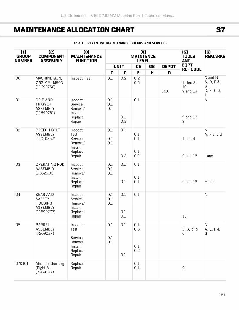
151
U.S. Ordnance | M60D 7.62MM Machine Gun | Technical Manual
MAINTENANCE ALLOCATION CHART 37
Table 1. PREVENTIVE MAINTENANCE CHECKS AND SERVICES
(1)GROUP
NUMBER
(2)COMPONENTASSEMBLY
(3)MAINTENANCE
FUNCTION
(5)TOOLS ANDEQPTREF CODE
(6)REMARKS
(4)MAINTENCE
LEVEL
UNIT
C0.1
0.10.10.1
0.1
0.10.1
0.10.10.1
0.10.10.1
0.1
0.10.1
Inspect, Test
InspectServiceRemove/InstallReplaceRepair
InspectTestServiceRemove/InstallReplaceRepair
InspectServiceRemove/InstallReplaceRepair
InspectServiceRemove/InstallReplaceRepair
InspectTest
ServiceRemove/InstallReplaceRepair
ReplaceRepair
MACHINE GUN, 7.62-MM, M60D (11699750)
GRIP AND TRIGGERASSEMBLY(11699751)
BREECH BOLTASSEMBLY(11010357)
OPERATING RODASSEMBLY(9362510)
SEAR AND SAFETYHOUSING ASSEMBLY(11699773)
BARRELASSEMBLY(7269027)
Machine Gun Leg (Right)A(7269047)
00
01
02
03
04
05
070101
0.20.5
0.1
0.10.1
0.10.2
0.1
0.10.1
0.1
0.10.3
0.10.2
0.10.1
0.2
0.10.3
0.1
0.2
0.1
0.1
0.1
0.10.1
0.1
0.1
15.0
1 thru 8,109 and 13
9 and 139
1 and 4
9 and 13
9 and 13
13
2, 3, 5, &6
9
C and NA, D, F &GC, E, F, G,JN
NA, F and G
I and
H and
N
NA, E, F &G
O F H D
DEPOTDS GS

152
Table 1. PREVENTIVE MAINTENANCE CHECKS AND SERVICES (cont)
(1)GROUP
NUMBER
(2)COMPONENTASSEMBLY
(3)MAINTENANCE
FUNCTION
(5)TOOLS ANDEQPTREF CODE
(6)REMARKS
(4)MAINTENCE
LEVEL
UNIT
C
0.10.1
0.10.1
0.10.1
0.10.1
0.1
0.1
ReplaceRepair
InspectServiceReplaceRepair
ReplaceRepair
ReplaceRepair
ReplaceRepair
ReplaceRepair
InspectServiceReplaceRepair
InspectServiceReplaceRepair
InspectServiceReplaceRepair
InspectTestServiceRepair
Machine Gun Leg (Left)(7269046)
COVER ASSEMBLY(7269114)
Feed Cam Assembly(11699814)
Lever Assembly(7269119)
Feed Pawl Assembly(7269120)
Cover Housing Assembly(7269118)
CARTRIDGE FEED TRAYASSEMBLY(7792096)
REAR SIGHT(11699796)
COCKING HANDLEASSEMBLY(7791621)
GUN RECEIVERASSEMBLY(11699805)
070102
06
0801
0802
0803
0804
07
08
09
10
0.10.1
0.1
0.10.3
0.10.1
0.10.1
0.10.1
0.50.2
0.1
0.20.2
0.1
0.20.2
0.10.3
0.1
0.1
0.1
0.10.2
0.1
0.1
0.1
0.2
0.5
0.2
9
9 and 13
9 and 13
9
9
9
13
13
9
7 and 8
9,10&13
N
N
NA and D
B, C, J, K
O F H D
DEPOTDS GS
U.S. Ordnance | M60D 7.62MM Machine Gun | Technical Manual
MAINTENANCE ALLOCATION CHART 37

153
Table 2. PREVENTIVE MAINTENANCE CHECKS AND SERVICES
TOOL ORTEST
EQUIPMENTREF CODE
MAINTENANCELEVEL
NATIONALSTOCK NUMBER
TOOLNUMBER
NOMENCLATURE
F
F
F
F
F
F
F
F
F
F
O
F
1
2
3
4
5
6
7
8
9
10
11
12
4933-00-653-3373
4933-00-647-3698
5220-00-745-8598
4933-00-653-9550
5210-00-234-5223
5210-00-254-4634
4933-00-754-0664
5120-00-078-8949
5120-00-077-2081
5140-00-473-6260
5180-00-357-7770
5133-00-262-2180
7274754
7274790
7458598
7799699
5910297
GGG-R-791or equivalent
AAA-S-133or equivalent
SC 4933-95-CL-A11
GGG-S-656or equivalent
8436748
D5-15-2119
GGG-D-751
U.S. Ordnance | M60D 7.62MM Machine Gun | Technical Manual
MAINTENANCE ALLOCATION CHART 37
GAUGE, FIRING PIN PROTRUSION
GAUGE, HEADSPACE: 1.6455 in.
GAUGE, PLUG PLAIN CYLINDRICAL
GAUGE, TEST BOLT
RULE, STEEL, MACHINIST’S
SCALE, DIAL INDICATING
TOOL KIT, SMALL ARMS: FIELDMAINTENANCE, POST, CAMP, ANDSTATION
SQUARE, COMBINATION
STOP, TOOL, SCREW
TOOL BOX, PORTABLE
TOOL KIT, SMALL ARMS REPAIRMAN
DRILL, TWIST: 1/8 in. dia., 5 1/8 in. long

154
Table 3. Remarks for Machine Gun M60D
REFERENCECODE
REMARKS
A Gauge annually using appropriate gauges.
B Receiver is a serialized item and not replaceable below depot level maintenance.
C Restamping or altering the serial number is prohibited.
D Receiver looseness check will be accomplished at time of repair and/or annual gauging cycle.
E Barrel and carry handle assembly will not be interchanged between weapons due to headspace requirements.
F Barrel and carry handle assembly will be issued only when complete weapon is checked for headspace requirements using the bolt that will be used in barrel.
G Breech bolt assembly will not be interchanged between weapons, and new breech bolt assembly will be checked for proper headspace requirements before returning to service.
H Burrs on the operating rod tower and yoke area is an inherent condition of the weapon. Organizational maintenance will remove small burrs and upset metal. Operating rod will not be rejected for this condition.
I Breech bolt assembly feed lug is prone to chipping and is an inherent condition of the weapon. Organizational maintenance will smooth surfaces by stoning. Breech bolt will not be rejected for this condition until the bottom camming lug begins to wear.
J Fabricated bucking bar anvil will be used to tighten rivets in receiver bridge.
K Riveting fixture will be used to tighten rivets in the magazine bracket to receiver surface.
L When a weapon is received by direct support with a maintenance request, all gaging requirements must be checked as a standard maintenance procedure. In addition, the weapon must be inspected and any other deficiencies found will be repaired, or noted for repair, at the appropriate maintenance level. As a minimum requirement, the M60D headspace must be verified annually by direct support personnel. This requirement could be increased to four times a year or after each training cycle depending on usage factors.
U.S. Ordnance | M60D 7.62MM Machine Gun | Technical Manual
MAINTENANCE ALLOCATION CHART 37

155
U.S . ORDN A NCE
M60DPROVEN UNDER FIRE

156
U.S . ORDN A NCE
M60DPROVEN UNDER FIRE

157
APPENDIX B | REPAIR PARTS AND SPECIAL TOOLS LIST

158
*SEE FIGURE 2 FOR FURTHER DISASSEMBLY
Figure 1. Group 00 Machine Gun, 7.62-MM, M60D
U.S. Ordnance | M60D 7.62MM Machine Gun | Technical Manual
GROUP 00: MACHINE GUN, 7.62MM, M60D 38REPAIR PARTS (1 OF 2)
15
14 12
13
4
2
*
13
119
8
7
6
5
10
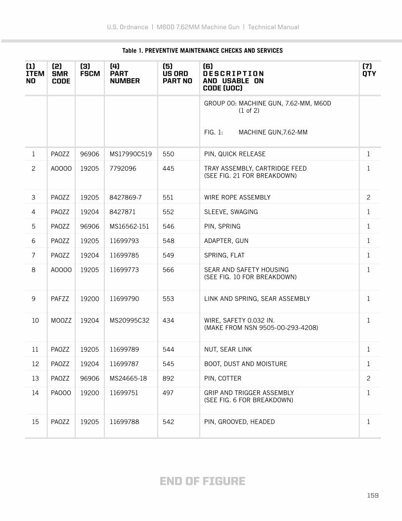
Table 1. PREVENTIVE MAINTENANCE CHECKS AND SERVICES
(1)ITEM NO
(2)SMR CODE
(3)FSCM
(5)US ORDPART NO
(6)D E S C R I P T I O N AND USABLE ON CODE (UOC)
(7)QTY
(4)PARTNUMBER
96906
19205
19205
19204
96906
19205
19204
19205
19200
19204
19205
19204
96906
19200
19205
550
445
551
552
546
548
549
566
553
434
544
545
892
497
542
PAOZZ
AOOOO
PAOZZ
PAOZZ
PAOZZ
PAOZZ PAOZZ AOOOO
PAFZZ
MOOZZ
PAOZZ
PAOZZ
PAOZZ PAOOO
PAOZZ
1
2
3
4
5
6
7
8
9
10
11
12
13
14
15
MS17990C519
7792096
8427869-7
8427871
MS16562-151
11699793
11699785
11699773
11699790
MS20995C32
11699789
11699787
MS24665-18
11699751
11699788
GROUP 00: MACHINE GUN, 7.62-MM, M60D (1 of 2)
FIG. 1: MACHINE GUN,7.62-MM
PIN, QUICK RELEASE
TRAY ASSEMBLY, CARTRIDGE FEED(SEE FIG. 21 FOR BREAKDOWN)
WIRE ROPE ASSEMBLY
SLEEVE, SWAGING
PIN, SPRING
ADAPTER, GUN
SPRING, FLAT
SEAR AND SAFETY HOUSING(SEE FIG. 10 FOR BREAKDOWN)
LINK AND SPRING, SEAR ASSEMBLY
WIRE, SAFETY 0.032 IN.(MAKE FROM NSN 9505-00-293-4208)
NUT, SEAR LINK
BOOT, DUST AND MOISTURE
PIN, COTTER
GRIP AND TRIGGER ASSEMBLY(SEE FIG. 6 FOR BREAKDOWN)
PIN, GROOVED, HEADED
1
1
2
1
1
1
1
1
1
1
1
1
2
1
1
END OF FIGURE159
U.S. Ordnance | M60D 7.62MM Machine Gun | Technical Manual

160
Figure 2. Group 00 Machine Gun, 7.62-MM, M60D
U.S. Ordnance | M60D 7.62MM Machine Gun | Technical Manual
GROUP 00: MACHINE GUN, 7.62MM, M60D 39REPAIR PARTS LIST (2 OF 2)
2
1
9
7
8
3
4
56
9
8

Table 1. PREVENTIVE MAINTENANCE CHECKS AND SERVICES
(1)ITEM NO
(2)SMR CODE
(3)FSCM
(5)US ORDPART NO
(6)D E S C R I P T I O N AND USABLE ON CODE (UOC)
(7)QTY
(4)PARTNUMBER
19204
19204
19204
19205
19205
19204
19204
19204
96906
380
479
381
550
877
663
486
892
382
PAFZZ
PAFZZ
PAFZZ
PAOOO
XAFDD
PAFZZ
PAFZZ
PAFZZ
PAFZZ
1
2
3
4
5
6
7
8
9
7790554
7792069
7790553
11699796
11699805
11686976
7792086
7790551
MS24665-18
GROUP 00: MACHINE GUN, 7.62-MM, M60D (2 of 2)
FIG. 2: MACHINE GUN,7.62-MM
LEVER, LOCK-RELEASE
PIN, STRAIGHT, HEADED
PAWL
SIGHT, REAR(SEE FIG. 25 FOR BREAKDOWN)
RECEIVER ASSEMBLY, GUN(SEE FIG. 28 FOR BREAKDOWN)
BRACKET, MAGAZINE
RIVET, SOLID
SPRING, HELICAL
PIN, COTTER
1
2
1
1
1
1
4
2
2
END OF FIGURE161
U.S. Ordnance | M60D 7.62MM Machine Gun | Technical Manual

162
Figure 3. Group 01 Grip and Trigger Assembly.
U.S. Ordnance | M60D 7.62MM Machine Gun | Technical Manual
GROUP 01: GRIP AND TRIGGER ASSEMBLY 40REPAIR PARTS LIST
2
1
9
43
5
6
6
7
7
8
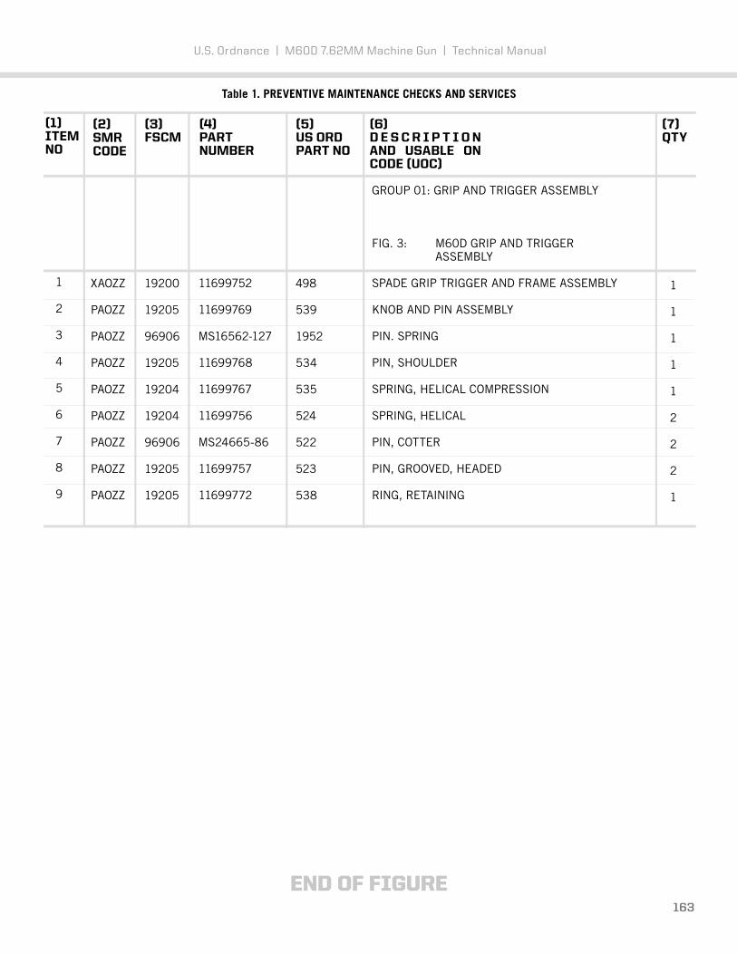
Table 1. PREVENTIVE MAINTENANCE CHECKS AND SERVICES
(1)ITEM NO
(2)SMR CODE
(3)FSCM
(5)US ORDPART NO
(6)D E S C R I P T I O N AND USABLE ON CODE (UOC)
(4)PARTNUMBER
19200
19205
96906
19205
19204
19204
96906
19205
19205
498
539
1952
534
535
524
522
523
538
XAOZZ
PAOZZ
PAOZZ
PAOZZ
PAOZZ
PAOZZ
PAOZZ
PAOZZ
PAOZZ
1
2
3
4
5
6
7
8
9
11699752
11699769
MS16562-127
11699768
11699767
11699756
MS24665-86
11699757
11699772
GROUP 01: GRIP AND TRIGGER ASSEMBLY
FIG. 3: M60D GRIP AND TRIGGER ASSEMBLY
SPADE GRIP TRIGGER AND FRAME ASSEMBLY
KNOB AND PIN ASSEMBLY
PIN. SPRING
PIN, SHOULDER
SPRING, HELICAL COMPRESSION
SPRING, HELICAL
PIN, COTTER
PIN, GROOVED, HEADED
RING, RETAINING
END OF FIGURE
(7)QTY
1
1
1
1
1
2
2
2
1
163
U.S. Ordnance | M60D 7.62MM Machine Gun | Technical Manual

164
Figure 4. Group 02 Breech Bolt Assembly.
U.S. Ordnance | M60D 7.62MM Machine Gun | Technical Manual
GROUP 02: BREECH BOLT ASSEMBLY. 41 REPAIR PARTS LIST
1
13
12
11
10
76
9
8
2
3
4
5

Table 1. PREVENTIVE MAINTENANCE CHECKS AND SERVICES
(1)ITEM NO
(2)SMR CODE
(3)FSCM
(5)US ORDPART NO
(6)D E S C R I P T I O N AND USABLE ON CODE (UOC)
(4)PARTNUMBER
19200
19204
19204
19204
19204
96906
19204
19204
19204
19204
19204
19204
19204
889
70
67
59
2548
581
903
627
65
69
2551
626
417
PAOZZ
PAOZZ
PAOZZ
PAOZZ
PAOZZ
PAOZZ
PAOZZ
PAOZZ
PAOZZ
PAOZZ
PAOZZ
PAOZZ
PAOZZ
1
2
3
4
5
6
7
8
9
10
11
12
13
9362505
7269063
7269087
7269065
11010376
MS39086-81
7269085
11010375
7269083
7269086
7790907
11010358
7792920
GROUP 02: BREECH BOLT ASSEMBLY 11010357
FIG. 4: BREECH BOLT ASSEMBLY
PLUG ASSEMBLY, BOLT
ACTUATOR ASSEMBLY, CAM
SPRING, HELICAL
GUIDE, FIRING PIN
PIN, FIRING
PIN, SPRING
SPRING, HELICAL
EJECTOR, CARTRIDGE
PLUNGER, EXTRACTOR
SPRING, HELICAL
EXTRACTOR, CARTRIDGE
BOLT, BREECH
PIN, STRAIGHT, HEADLESS
END OF FIGURE
(7)QTY
1
1
1
1
1
1
1
1
1
1
1
1
1
165
U.S. Ordnance | M60D 7.62MM Machine Gun | Technical Manual

166
Figure 5. Group 03 Operating Rod Assembly.
U.S. Ordnance | M60D 7.62MM Machine Gun | Technical Manual
GROUP 03: OPERATING ROD ASSEMBLY 42REPAIR PARTS LIST
4
3
1
2

Table 1. PREVENTIVE MAINTENANCE CHECKS AND SERVICES
(1)ITEM NO
(2)SMR CODE
(3)FSCM
(5)US ORDPART NO
(6)D E S C R I P T I O N AND USABLE ON CODE (UOC)
(4)PARTNUMBER
19200
19200
96906
19200
2555
2558
636
2556
PAFZZ
XAFZZ
PAFZZ
PAFZZ
1
2
3
4
9362506
9362509
MS51923-105
9362507
GROUP 03: OPERATING ROD ASSEMBLY
FIG. 5: OPERATING ROD ASSEMBLY
ROLLER, YOKE
YOKE AND TUBE ASSEMBLY
PIN, SPRING
PIN, STRAIGHT, HEADLESS
END OF FIGURE
(7)QTY
1
1
1
1
167
U.S. Ordnance | M60D 7.62MM Machine Gun | Technical Manual

168
Figure 6. Group 04 Sear and Safety Housing Assembly.
U.S. Ordnance | M60D 7.62MM Machine Gun | Technical Manual
GROUP 04: SEAR AND SAFETY HOUSING ASSEMBLY 43REPAIR PARTS LIST
4
8
9
10
6
7
5
3
2
1

Table 1. PREVENTIVE MAINTENANCE CHECKS AND SERVICES
(1)ITEM NO
(2)SMR CODE
(3)FSCM
(5)US ORDPART NO
(6)D E S C R I P T I O N AND USABLE ON CODE (UOC)
(4)PARTNUMBER
19204
19205
19204
19204
19204
19204
19204
19204
19205
19205
578
577
574
576
201
199
203
575
568
567
PAOZZ
PAOZZ
PAOZZ
PAOZZ
PAOZZ
PAOZZ
PAOZZ
PAOZZ
PAOZZ
XAOZZ
1
2
3
4
5
6
7
8
9
10
11699775
11699776
11699779
11699778
7269209
7269207
7269211
11699777
11699780
11699774
GROUP 04: SEAR AND SAFETY HOUSING ASSEMBLY
FIG. 6: M60D SEAR AND SAFETY HOUSING ASSY
SPRING, HELICAL
PLUNGER, SAFETY
PIN, GROOVED, HEADED
BUSHING, SLEEVE
SEAR
PLUNGER, SEAR
SPRING, HELICAL
SAFETY, SMALL ARMS
ACTIVATOR, SEAR
HOUSING, SEAR
END OF FIGURE
(7)QTY
1
1
1
1
1
1
1
1
1
1
169
U.S. Ordnance | M60D 7.62MM Machine Gun | Technical Manual

170
Figure 7. Group 05 Barrel and Carry Handle Assembly.
U.S. Ordnance | M60D 7.62MM Machine Gun | Technical Manual
GROUP 05: BARREL ASSEMBLY 44 REPAIR PARTS LIST
7
8
9
1113
10
12
5
6
4
3
1
2

Table 1. PREVENTIVE MAINTENANCE CHECKS AND SERVICES
(1)ITEM NO
(2)SMR CODE
(3)FSCM
(5)US ORDPART NO
(6)D E S C R I P T I O N AND USABLE ON CODE (UOC)
(4)PARTNUMBER
19204
19204
19204
19204
19204
19204
19204
96906
19205
19205
19204
19205
96906
2402
758
762
2413
434
2531
761
913
PAFZZ
PAFZZ
PAFZZ
PAFZZ
NPNLW
PAFZZ
PAFZZ
PAFZZ
PAOZZ
PAOZZ
PAOZZ
PAOZZ
PAOZZ
1
2
3
4
5
6
7
8
9
10
11
12
13
7269028
7269031
7269035
7791247
MS2099SC32
7269030
7269034
12599983
7269213
7269302
7269250
11010377
MS30986-81
GROUP 05: BARREL ASSEMBLY
FIG. 7: BARREL ASSEMBLY
BARREL AND CARRY HANDLE ASSEMBLY
LOCKNUT, GAS, CYLINDER
PLUG, VENT
PISTON, GAS
WIRE, SAFETY 0.032 IN. CUT FROM NSN 9505-00-293-4208
EXTENSION, GAS CYLINDER
SUPPRESSOR, FLASH
PIN, STRAIGHT
CARRY HANDLE ASSEMBLY
HELICAL COMPRESSION SPRING DETENT PLUNGER
BARREL LOCK RING
SPRING PIN
END OF FIGURE
(7)QTY
1
1
2
1
1
1
1
1
1
2
2
1
1
171
U.S. Ordnance | M60D 7.62MM Machine Gun | Technical Manual

172
Figure 8. Group 0701 Machine Gun Bipod.
U.S. Ordnance | M60D 7.62MM Machine Gun | Technical Manual
GROUP 0701: MACHINE GUN BIPOD 45REPAIR PARTS LIST
1111
2
9
9
10
10
3
4
5
6
1
3
7 7
8
8

Table 1. PREVENTIVE MAINTENANCE CHECKS AND SERVICES
(1)ITEM NO
(2)SMR CODE
(3)FSCM
(5)US ORDPART NO
(6)D E S C R I P T I O N AND USABLE ON CODE (UOC)
(4)PARTNUMBER
2804
2807
2808
2811
2814
2815
2816
2843
2666
753
2817
1
2
3
4
5
6
7
8
9
10
11
SB2804
SC2807
SB2808
SB2811
SB2814
SB2815
SB2816
2843
SB25064
7269050
SC2817
GROUP 0701: BIPOD ASSEMBLY
FIG. 8: MACHINE GUN BIPOD
PIVOT ASSEMBLY, BIPOD
LEG ASSEMBLY, BIPOD
LEG ASSEMBLY INNER
LEG ASSEMBLY, OUTER
LOCK, LEG, BIPOD
RING, LOCK, BIPOD
PIN, LOCK, BIPOD
PIN, DOWEL
SPRING, HELICAL COMPRESSION
PLUNGER, SPRING, LEG
SCREW, PIVOT, LEG
END OF FIGURE
(7)QTY
1
1
2
2
2
2
2
2
2
2
2
173
U.S. Ordnance | M60D 7.62MM Machine Gun | Technical Manual

174
Figure 9. Group 07 Cover and Lever Assembly.
U.S. Ordnance | M60D 7.62MM Machine Gun | Technical Manual
GROUP 07: COVER AND FEED LEVER ASSEMBLY, 46REPAIR PARTS LIST
56
3
2
4
1
8
9
7

Table 1. PREVENTIVE MAINTENANCE CHECKS AND SERVICES
(1)ITEM NO
(2)SMR CODE
(3)FSCM
(5)US ORDPART NO
(6)D E S C R I P T I O N AND USABLE ON CODE (UOC)
(4)PARTNUMBER
19204
19204
19204
19204
19204
19204
19204
96906
19204
653
100
99
147
599
150
593
892
29056
PAFFF
PAFZZ
PAFZZ
AFFFF
PAOZZ
PAFFF
PAFZZ
PAOZZ
PAFHH
1
2
3
4
5
6
7
8
9
11699814
7269117
7269116
7269119
11686315
7269120
11010152
MS24665-18
7269118
GROUP 07: COVER AND FEED LEVER ASSEMBLY
FIG. 9: COVER AND FEED LEVER ASSEMBLY
CAM ASSEMBLY, FEED (SEE FIG.16 FORASSEMBLY BREAKDOWN)
GUIDE, CARTRIDGE REAR
GUIDE, CARTRIDGE FRONT
LEVER ASSEMBLY, FEED (SEE FIG.16FOR ASSEMBLY BREAKDOWN)
SPRING, HELICAL
PAWL ASSEMBLY, CAM FEED (SEE FIG.17FOR ASSEMBLY BREAKDOWN)
SHAFT, STRAIGHT
PIN, COTTER
HOUSING ASSEMBLY, COVER (SEE FIG.18 FOR ASSEMBLY BREAKDOWN)
END OF FIGURE
(7)QTY
1
1
1
1
1
1
1
1
1
175
U.S. Ordnance | M60D 7.62MM Machine Gun | Technical Manual

(1)ITEM NO
(2)SMR CODE
(3)FSCM
(5)US ORDPART NO
(6)D E S C R I P T I O N AND USABLE ON CODE (UOC)
(4)PARTNUMBER
19204
19204
19204
19204
19204
19204
132
134
654
133
148
149
PAFZZ
PAFZZ
XAFZZ
PAFZZ
PAFZZ
PAFZZ
1
2
3
4
5
6
7269123
7269125
11699817
7269124
7269146
7269145
GROUP 0801: FEED CAM ASSEMBLY GROUP 0802: FEED LEVEL ASSEMBLY
FIG. 10: FEED CAM ASSEMBLY AND FEED LEVER ASSEMBLY
PLUNGER, RETAINER
SPRING, HELICAL
CAM ASSEMBLY
RETAINER, FEED CAM
CLIP, SPRING LEVER
LEVER, FEED
END OF FIGURE
(7)QTY
1
1
1
1
1
1
176
Figure 10. Group 0801 and 0802 Feed Cam Assembly and Feed Lever Assembly
U.S. Ordnance | M60D 7.62MM Machine Gun | Technical Manual
GROUP 0801: FEED CAM ASSEMBLY, 47GROUP 0802: FEED LEVER ASSEMBLY, REPAIR PARTS LIST
1 2
3
45
6

(1)ITEM NO
(2)SMR CODE
(3)FSCM
(5)US ORDPART NO
(6)D E S C R I P T I O N AND USABLE ON CODE (UOC)
(4)PARTNUMBER
1 7269120
GROUP 0803: FEED PAWL ASSEMBLY
FIG. 11: FEED PAWL ASSEMBY
FEED PAWL
END OF FIGURE
(7)QTY
1
177
Figure 11. Group 0803 Feed Pawl Assembly.
U.S. Ordnance | M60D 7.62MM Machine Gun | Technical Manual
GROUP 0803: FEED PAWL ASSEMBLY, 48REPAIR PARTS LIST
1

178
Figure 12. Group 0804 Cover Housing Assembly
U.S. Ordnance | M60D 7.62MM Machine Gun | Technical Manual
GROUP 0804: COVER HOUSING ASSEMBLY, 49REPAIR PARTS LIST
12
3
5
4
8
7
6
9

Table 1. PREVENTIVE MAINTENANCE CHECKS AND SERVICES
(1)ITEM NO
(2)SMR CODE
(3)FSCM
(5)US ORDPART NO
(6)D E S C R I P T I O N AND USABLE ON CODE (UOC)
(4)PARTNUMBER
19204
19204
19205
19204
19200
19204
19204
19205
19204
104
109
413
126
888
108
111
110
641
PAFZZ
PAFZZ
PAHZZ
PAFZZ PAFZZ
PAHZZ
PAHZZ
PAHZZ
XAHZZ
1
2
3
4
5
6
7
8
9
7269136
7791271
7791270
7269137
9362520
7269141
7269144
7269143
7269128
GROUP 0804: COVER HOUSING ASSEMBLY
FIG. 12: COVER HOUSING ASSEMBLY
LATCH, COVER
SPRING, HELICAL
LATCH LEVER ASSEMBLY
PIN, LATCH LEVER
SPRING BUMPER CAM
SPRING, HELICAL
WASHER, FLAT
PIN, SHOULDER, HEADED
FRAME ASSEMBLY, COVER
END OF FIGURE
(7)QTY
1
1
1
1
1
2
2
2
1
179
U.S. Ordnance | M60D 7.62MM Machine Gun | Technical Manual

(1)ITEM NO
(2)SMR CODE
(3)FSCM
(5)US ORDPART NO
(6)D E S C R I P T I O N AND USABLE ON CODE (UOC)
(4)PARTNUMBER
19204
19204
19204
19204
19204
445
446
320
319
317
321
XAOZZ
PAOZZ
PAOZZ
PAOZZ
PAOZZ
1
2
3
4
5
6
7792096
7792097
7790724
7269333
7269332
7269335
GROUP 9: CARTRIDGE FEED TRAY ASSY
FIG. 13: CARTRIDGE FEED TRAY ASSY
CARTRIDGE FEED TRAY ASSEMBLY
FRAME ASSEMBLY, CARTRIDGE TRAY
SHAFT, CARTRIDGE
ROLLER, LINEAR-ROTARY
PAWL, CARTRIDGE RETAINER
SPRING, HELICAL
END OF FIGURE
(7)QTY
1
1
1
2
1
1
180
Figure 13. Group 9 Cartridge Feed Tray Assembly.
U.S. Ordnance | M60D 7.62MM Machine Gun | Technical Manual
GROUP 9: CARTRIDGE FEED TRAY ASSEMBLY 50 REPAIR PARTS LIST
1
3
6
2
5
4

(1)ITEM NO
(2)SMR CODE
(3)FSCM
(5)US ORDPART NO
(6)D E S C R I P T I O N AND USABLE ON CODE (UOC)
(4)PARTNUMBER
96906
19204
96906
96906
19205
19205
19205
563
565
561
560
562
559
564
PAFZZ
PAFZZ
PAFZZ
PAFZZ
PAFZZ
PAFZZ
PAFZZ
1
2
3
4
5
6
7
MS16562-119
11699799
MS19059-2412
MS24585-75
11699798
11699797
11699763
GROUP 10: REAR SIGHT
FIG. 14: M60D REAR SIGHT
PIN, SPRING
RING, SIGHT
BALL, BEARING
SPRING, HELICAL
RETAINER, REAR SIGHT
BASE, REAR SIGHT
NUT, SELF-LOCKING
END OF FIGURE
(7)QTY
1
1
1
1
1
1
1
181
Figure 14. Group 10 Rear Sight.
U.S. Ordnance | M60D 7.62MM Machine Gun | Technical Manual
GROUP 10: REAR SIGHT 51REPAIR PARTS LIST
1
7
6
2
3
4
5

(1)ITEM NO
(2)SMR CODE
(3)FSCM
(5)US ORDPART NO
(6)D E S C R I P T I O N AND USABLE ON CODE (UOC)
(4)PARTNUMBER
19205
19205
19205
222
487
225
PAFZZ
PAFZZ PAFZZ
1
2
3
7269237
7791522
7269239
GROUP 11: COCKING HANDLE ASSEMBLY
FIG. 15: COCKING HANDLE ASSEMBLY
RETAINER, COCKING HANDLE
SPRING, HELICAL
SLIDE ASSEMBLY
END OF FIGURE
(7)QTY
1
1
1
182
Figure 15. Group 11 Cocking Handle Assembly.
U.S. Ordnance | M60D 7.62MM Machine Gun | Technical Manual
GROUP 11: COCKING HANDLE ASSEMBLY, 52REPAIR PARTS LIST
2
1
3

(1)ITEM NO
(2)SMR CODE
(3)FSCM
(5)US ORDPART NO
(6)D E S C R I P T I O N AND USABLE ON CODE (UOC)
(4)PARTNUMBER
19205
19204
19204
19200
364
881
401
877
PAFZZ
PAFZZ
PAFZZ
XADDA
1
2
3
4
7269411
7792972
7792974
11686307
GROUP 12: GUN RECEIVER ASSEMBLY
FIG. 16: M60D GUN RECEIVER ASSEMBLY
RIVET, SOLID
RIVET, SOLID
PLATE, MOUNTING
RECEIVER ASSEMBLY
END OF FIGURE
(7)QTY
4
2
1
1
183
Figure 16. Group 12 Gun Receiver Assembly.
U.S. Ordnance | M60D 7.62MM Machine Gun | Technical Manual
GROUP 12: GUN RECEIVER ASSEMBLY 53 REPAIR PARTS LIST
21
4
3

U.S. Ordnance | M60D 7.62MM Machine Gun | Technical Manual
GROUP 9500: ECHELON TOOL KIT 54
184
Figure 17. Group 9500 Echelon Tool Kit.
24
17
12
10
16
251
2
3
4
5
6
7
151427
13
9
8
11
22
26
21
23
2019 18

Table 1. PREVENTIVE MAINTENANCE CHECKS AND SERVICES
(1)ITEM NO
(2)SMR CODE
(3)FSCM
(5)US ORDPART NO
(6)D E S C R I P T I O N AND USABLE ON CODE (UOC)
(4)PARTNUMBER
1
2
3
4
5
6
7
8
9
10
11
12
13
14
15
16
17
18
19
20
21
22
23
24
25
26
27
B123
B55
2505
B42
29026
29028
29021
29019
29018
29025
29011
29013
29024
29159
7799699
29881
29148
29160
29033
29010
2537
29048
29009
29015
29016
29014
29003
GROUP 9500: ECHELON TOOL KIT
FIG. 17: ECHELON TOO KIT
Section, Cleaning Rod
Holder, Cleaning Patch
Wrench, Screwdriver and Reamer
Extractor, Ruptured CTG
M60 Brush, Chamber
M60 Brush, Bore
M60/M2 Patch, Cleaning
Punch, Starrett 3/32”
Punch, Starrett 1/16”
Brush, Receiver
Brass Punch 5/16” x ½”
Long Nose Pliers
M2/M60 Slip 2000 Lubrication
Firing Pin Protrusion Gauge
Bolt Gauge
Diamond Needle Files
Spool, Safety Wire
Safety Wire Pliers
Pliers, 6”
Steel Hammer
Wrench, Cover Latch
3/32” Allen Wrench
Brass Hammer
1/8” Allen Wrench
Scribe
Screwdriver
Field Headspace Gauge
(7)QTY
185
U.S. Ordnance | M60D 7.62MM Machine Gun | Technical Manual

186
U.S . ORDN A NCE
M60DPROVEN UNDER FIRE

CONTACT U.S. ORDNANCE IF WEAPON HAS ISSUES OR TO REPALACE PARTS
W e b s i t e : W W W. U S O R D . C O M | P h o n e : 7 7 5 . 3 4 3 . 1 3 2 0 | F a x : 7 7 5 . 3 4 3 . 1 3 3 1
Please be clear with your request. Before contacting U.S. Ordnance know and refer to the PART NUMBER, PAGE NUMBER, FIGURE NUMBERwhen describing the issue or part replacemnet.
187
U.S. Ordnance | M60D 7.62MM Machine Gun | Technical Manual

188
USORD.COM
P h :7 7 5 . 3 4 3 . 1 3 2 0 I S O 9 0 0 1 : 2 0 8 8 F a x :7 7 5 . 3 4 3 . 1 3 3 1