Embed Size (px)
Citation preview

ARMY TM 9-1005-224-23&PAIR FORCE T.O. 11W2-6-4-11
Supersedes Copy Dated July 1987See Page i for details
TECHNICAL MANUAL
UNIT AND DIRECT MAINTENANCE MANUAL(INCLUDING REPAIR PARTS AND SPECIAL TOOLS LIST)
FORMACHINE GUN, 7.62-MM, M60 W/E
(1005-00-605-7710) (EIC: 4AJ)AND
MACHINE GUN, 7.62-MM, M60D W/E(1005-00-909-3002) (EIC: 4A8)
INTRODUCTION
UNIT MAINTENANCEINSTRUCTIONS
DIRECT AND GENERAL SUPPORTMAINTENANCE INSTRUCTIONS
MAINTENANCE OF AUXILIARYEQUIPMENT
REFERENCES
MAINTENANCE ALLOCATIONCHART
REPAIR PARTS AND SPECIALTOOLS LIST
EXPENDABLE/DURABLESUPPLIES AND MATERIALS LIST
ILLUSTRATED LIST OFMANUFACTURED ITEMS
ALPHABETICAL INDEX
DISTRIBUTION STATEMENT:Approved for public release; distribution is unlimited.
HEADQUARTERS, DEPARTMENTS OF THE ARMY AND AIR FORCE
MAY 1998

WARNING
The M240 Series Machine Guns must be inspected and gaged at least once annually for safety andserviceability. Initial gaging is required one year from receipt of the weapons. Air Force users refer toinspection requirements in Air Force Manual (AFM) 36-2227-1, Volume 1.
All Army Reserve and Army National Guard M240 Series Machine Guns must be inspected and gaged atleast every two years, after initial inspection/gaging procedures have been accomplished. This initialgaging procedure is required one year from receipt of the weapons. This two year interval may bemaintained unless preventive maintenance checks and services (PMCS) or other physical evidenceindicates that an individual unit’s M240 Machine Guns require inspection/gaging at a more frequentinterval. If it is determined that a yearly inspection is necessary for an individual unit, only that unit will beaffected. That will not affect other units in regard to the interval of inspection.
Dry cleaning solvent (SD) is flammable.
Do not clean parts near an open flame or in a smoking area. Dry cleaning solvent evaporates quickly andhas a drying effect on the skin. When used without protective gloves, solvent may cause irritation to orcracking of the skin.
Personnel operating vapor degreaser are warned not to breathe the vapor fumes.
Before starting an inspection, be sure to clear the weapon. Do not actuate the trigger before clearing theweapon. Inspect the chamber to make sure it is empty and free of obstructions. Check to see there areno obstructions in the barrel and no ammunition is in position to be chambered.
Using paint thinners, gasoline, kerosene, benzene (benzol), water, steam, or air for cleaning the weaponis prohibited. Use only authorized cleaning materials.
Be careful when removing and installing spring-loaded components. Carelessness could cause injury.
To prevent possible body injuries and aircraft damage, personnel should not stand the weapon on itsbarrel assembly when disassembling or assembling the weapon.
For additional first aid data, see FM 21-11.

TECHNICAL MANUAL
No. 9-1005-224-23&P
*ARMY TM 9-1005-224-23&PAIR FORCE T.O. 11W2-6-4-11
HEADQUARTERSDEPARTMENTS OF THE ARMY
AND AIR FORCEWashington D.C., 21 May 1998
Unit and Direct Support Maintenance Manual(Including Repair Parts and Special Tools List)
forMACHINE GUN, 7.62-MM, M60 W/E
(1005-00-605-7710)and
MACHINE GUN, 7.62-MM, M60D W/E(1006-00-909-3002)
DISTRIBUTION STATEMENT: Approved for Public Release; Distribution Is Unlimited.
REPORTING ERRORS AND RECOMMENDING IMPROVEMENTS
You can help improve this manual. If you find any mistakes or if you know of a way to improvethe procedures, please let us know. Army users mail your letter, DA Form 2028 (RecommendedChanges to Publications and Blank Forms), or DA Form 2028-2 located in the back of this manualdirect to: Director, Armament and Chemical Acquisition & Logistics Activity, ATTN: AMSMC-NML,Rock Island, IL 61299-7630. Air Force users submit AFTO Form 22, Technical Order SystemPublication Improvement Report and Reply, to: WR-ALC/MMIBTC, Robins AFB, GA 31098-5330.A reply will be furnished to you.
*This TM supersedes TM 9-1005-224-24, dated 8 July 1987; TM 9-1005-224-24P, 23 July 1987; andTB 9-1005-224-50-1, dated 7 October 1994, including all changes.
i

TM 9-1005-224-23&P
Work Package
WARNING SUMMARY
CHAPTER 1 INTRODUCTIONGeneral Information. .........................................................................................................Equipment Description and Data
WP 0001 00....................................................................................... WP 0002 00
CHAPTER 2 UNIT MAINTENANCE INSTRUCTIONSRepair Parts, Special Tools, and Support EquipmentService Upon Receipt
........................................................ WP 0003 00.......................................................................................................
Preventive Maintenance Checks and Services (PMCS)WP 0004 00
Troubleshooting..................................................... WP 0005 00
............................................................................................................Maintenance Procedures
WP 0006 00.................................................................................................. WP 0007 00 thru
Lubrication InstructionsWP 0009 00
...................................................................................................Preparation for Storage or Shipment
WP 0020 00................................................................................. WP 0021 00
CHAPTER 3 DIRECT MAINTENANCE INSTRUCTIONSRepair Parts, Special Tools, and Support EquipmentTroubleshooting
........................................................ WP 0022 00................................................................................................................
Maintenance ProceduresWP 0023 00
.................................................................................................. WP 0024 00 thru
Preembarkation Inspection of Materiel in Units Alerted forWP 0044 00
Overseas Movement .......................................................................................................Preparation for Storage or Shipment
WP 0045 00............................................................................... WP 0046 00
APPENDIX A REFERENCES ........................................................................................ WP 0047 00
APPENDIX B MAINTENANCE ALLOCATION CHART ................................................. WP 0048 00
APPENDIX C REPAIR PARTS AND SPECIAL TOOLS LISTSIntroduction ....................................................................................................................... WP 0049 00Group 00
Group 01Group 02Group 03Group 04Group 05Group 06Group 07Group 0701Group 070101Group 070102Group 08Group 0801Group 0802Group 0803Group 0804
Machine Gun, 7.62-mm M60 and M60D (M60 Major Assemblies) ......Machine Gun, 7.62-mm M60 and M60D (M60 Minor Components)
WP 0050 00...... WP 0051 00
Machine Gun, 7.62-mm M60 and M60D (M60D Major Assemblies)....... WP 0052 00Machine Gun, 7.62-mm M60 and M60D (M60D Minor Components)..... WP 0053 00Shoulder Gun Stock Assembly (M60 only)Grip and Trigger Assembly (M60D only)
............................................ WP 0054 00................................................
Breech Bolt AssemblyWP 0055 00
Operating Rod Assembly.................................................................... WP 0056 00
......................................................................Trigger Mechanism Grip Assembly (M60 only)
WP 0057 00......................................
Sear and Safety Housing Assembly (M60D only)WP 0058 00
..................................Barrel and Bipod Assembly
WP 0059 00...................................................................
Machine Gun BipodWP 0060 00
..............................................................................Machine Gun Leg (Right)
WP 0061 00.....................................................................
Machine Gun Leg (Left)WP 0062 00
........................................................................Cover and Lever Assembly
WP 0063 00................................................................... WP 0064 00
Feed Cam Assembly ..........................................................................Feed Lever Assembly
WP 0065 00............................................................................
Feed Pawl AssemblyWP 0065 00
........................................................................... WP 0066 00Cover Housing Assembly .................................................................... WP 0067 00
ii

Group 09 Tray and Hanger Assembly (M60 only) ................................................. WP 0068 00Group 0901 Cartridge Feed Tray Assembly (M60 only) ............................................ WP 0069 00Group 10 Cartridge Feed Tray Assembly (M60D only). ......................................... WP 0070 00Group 11 Forearm Assembly (M60 only) .............................................................. WP 0071 00Group 12 Rear Sight (M60 only) ........................................................................... WP 0072 00Group 1201 Rear Sight Leaf Assembly (M60 only) ................................................... WP 0073 00Group 13 Rear Sight (M60D only). ........................................................................ WP 0074 00Group 14 Cocking Handle Assembly .................................................................... WP 0075 00Group 15 Gun Receiver Assembly (M60 only) ...................................................... WP 0076 00Group 16 Gun Receiver Assembly (M60D only). ................................................... WP 0077 00Group 9999 Bulk Materials List ................................................................................. WP 0078 00
TM 9-1005-224-23&P
Work Package
SPECIAL TOOL LISTGroup 9500 Special Tools ........................................................................................ WP 0079 00
Part Number Index.. ........................................................................................................ WP 0080 00National Stock Number Index ............................................................................................ WP 0081 00
APPENDIX D EXPENDABLE/DURABLE SUPPLIES AND MATERIALS LIST .......... WP 0082 00
APPENDIX E ILLUSTRATED LIST OF MANUFACTURED ITEMS .......................... WP 0083 00
ALPHABETICAL INDEX .................................................................................................. WP 0084 00
iii/ iv blank


TM 9-1005-224-23&P
M60, 7.62-MM, MACHINE GUN
M60D, 7.62-MM, MACHINE GUN
Full External Views


TM 9-1005-224-23&P
CHAPTER 1
INTRODUCTION


TM 9-1005-224-23&P
GENERAL INFORMATION 0001 00
SCOPE
a. Type of Manual: Unit, Direct Support, Maintenance Manual.
b. Model Numbers and Equipment Names:
(1) M60 7.62-mm machine gun
(2) M60D 7.62-mm machine gun
c. Purpose of Equipment:
(1) The M60 7.62-mm machine gun is a general purpose weapon capable of being fired fromseveral mounts or while being handheld. The weapon is mainly used for ground operations.
(2) The M60D 7.62-mm machine gun is a general purpose weapon capable of being fired fromseveral mounts. The weapon is mainly used for support of ground operations. The M60D isan aircraft door-mounted, or vehicle mounted machine gun.
MAINTENANCE FORMS, RECORDS, AND REPORTS
Department of the Army forms and procedures for equipment maintenance will be those prescribed byDA PAM 738-750, The Army Maintenance Management System (TAMMS).
DESTRUCTION OF ARMY MATERIEL TO PREVENT ENEMY USE
Procedures and materials used for the destruction of the machine guns and tripod mount will be found inTM 750-244-7.
PREPARATION FOR STORAGE OR SHIPMENT
Requirements for storage or shipment are listed in TM 9-1005-224-10.
OFFICIAL NOMENCLATURE, NAMES AND DESIGNATIONS
This listing includes nomenclature cross-references used in this manual:
NOMENCLATURE CROSS-REFERENCE LIST
Common Name Official Nomenclature
Bipod Legs . . . . . . . . . . . . . . . . . . . . . . . . . . . . . . . . . . . . . . . . . . . . . . . . . . . Leg, Machine Gun, RHLeg, Machine Gun, LH
Leaf Assembly . . . . . . . . . . . . . . . . . . . . . . . . . . . . . . . . . . . . . . . . . . . . . Leaf Assembly, Rear Sight
0001 00-1

TM 9-1005-224-23&P
GENERAL INFORMATlON (cont) 0001 00
REPORTING EQUIPMENT IMPROVEMENT RECOMMENDATIONS (EIR)
If your machine gun or tripod mount needs improvement, let us know. Send us an EIR. You, the user,are the only one who can tell us what you don’t like about your equipment. Let us know why you don’tlike the design. Put it on an SF 368 Quality Deficiency Report (QDR). Mail it to us at Director, Armamentand Chemical Acquisition & Logistics Activity, ATTN: AMSMC-QAD, Rock Island, IL 61299-6000. We’llsend you a reply.
CORROSION PREVENTION AND CONTROL (CPC)
CPC of Army materiel is a continuing concern. It is important that any corrosion problems with this itembe reported so that the problem can be corrected and improvements can be made to prevent the problemin future items.
While corrosion is typically associated with rusting of metals, it can also include deterioration of othermaterials such as rubber and plastic. Unusual cracking, softening, swelling, or breaking of thesematerials may be a corrosion problem.
If a corrosion problem is identified, it can be reported using Standard Form 368, Product QualityDeficiency Report. Use of key words such as corrosion, rust, deterioration, or cracking will assure thatthe information is identified as a CPC problem.
Army users submit Product Quality Deficiency Report (SF 368) to: Director, Armament and ChemicalAcquisition & Logistics Activity, ATTN: AMSMC-QAD/Customer Feedback Center, Rock Island, IL61299-6000.
0001 00-2

TM 9-1005-224-23&P
EQUIPMENT DESCRIPTION AND DATA 0002 00
EQUIPMENT CHARACTERISTICS, CAPABILITIES, AND FEATURES
a. M60 Machine Gun. The M60 machine gun is an air-cooled, link-belt fed, gas operated weapon.The operating cycle begins from an open bolt position. The weapon features fixed head space,which permits rapid changing of barrels.
b. M60D Machine Gun. The M60D machine gun is an air-cooled, link-belt fed, gas operatedweapon. The operating cycle begins from an open bolt position. The weapon features fixed headspace, which permits rapid changing of barrels.
M60 Machine Gun
M60D Machine Gun
0002 00-1
TM 9-1005-224-23&P
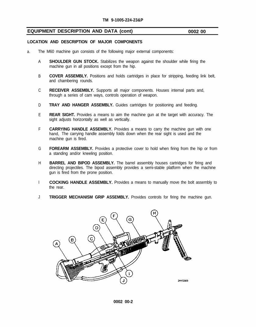
EQUIPMENT DESCRIPTION AND DATA (cont) 0002 00
LOCATION AND DESCRIPTION OF MAJOR COMPONENTS
a. The M60 machine gun consists of the following major external components:
A
B
C
D
E
F
G
H
I
J
SHOULDER GUN STOCK. Stabilizes the weapon against the shoulder while firing themachine gun in all positions except from the hip.
COVER ASSEMBLY. Positions and holds cartridges in place for stripping, feeding link belt,and chambering rounds.
RECEIVER ASSEMBLY. Supports all major components. Houses internal parts and,through a series of cam ways, controls operation of weapon.
TRAY AND HANGER ASSEMBLY. Guides cartridges for positioning and feeding.
REAR SIGHT. Provides a means to aim the machine gun at the target with accuracy. Thesight adjusts horizontally as well as vertically.
CARRYING HANDLE ASSEMBLY. Provides a means to carry the machine gun with onehand, The carrying handle assembly folds down when the rear sight is used and themachine gun is fired.
FOREARM ASSEMBLY. Provides a protective cover to hold when firing from the hip or froma standing and/or kneeling position.
BARREL AND BIPOD ASSEMBLY. The barrel assembly houses cartridges for firing anddirecting projectiles. The bipod assembly provides a semi-stable platform when the machinegun is fired from the prone position.
COCKING HANDLE ASSEMBLY.the rear.
Provides a means to manually move the bolt assembly to
TRIGGER MECHANISM GRIP ASSEMBLY. Provides controls for firing the machine gun.
0002 00-2

TM 9-1005-224-23&P
b. The M60D machine gun consists of the following major components:
A
B
C
D
E
F
G
H
I
GRIP AND TRIGGER ASSEMBLY. Provides handles to move machine gun toward thetarget and houses the machine gun trigger.
COVER ASSEMBLY. Positions and holds cartridges in place for stripping, feeding link belt,and chambering rounds.
CARTRIDGE FEED TRAY ASSEMBLY. Guides cartridges for positioning and feeding.
REAR SIGHT. Provides a means to aim the machine gun in the general area of the target.The rear sight is non adjustable.
CARRYING HANDLE ASSEMBLY. Provides a means to carry the machine gun with onehand. The carrying handle assembly folds down when the rear sight is used and themachine gun is fired.
BARREL AND BIPOD ASSEMBLY. The barrel assembly houses cartridges for firing anddirecting projectiles. The bipod assembly provides a semi-stable platform when the machinegun is fired from other than the designated mount.
RECEIVER ASSEMBLY. Supports all major components. Houses internal parts and,through a series of cam ways, controls operation of weapon.
COCKING HANDLE ASSEMBLY. Provides a means to manually move the bolt assembly tothe rear.
SEAR AND SAFETY HOUSING. Provides controls for firing the machine gun.
0002 00-3

TM 9-1005-224-23&P
EQUIPMENT DESCRIPTION AND DATA (cont) 0002 00
DIFFERENCES BETWEEN MODELS
Differences between the M60 and M60D machine gun are listed below.
Assembly/Component
Tray and hanger assemblyCartridge feed tray assemblyDust and moisture seal bootForearm assemblyGrip and trigger assemblyGun adapterBandoleer hanger assemblyMagazine bracket assemblyRear sight (adjustable)Rear sight (non adjustable)Receiver assemblyReceiver assemblySear and safety housing assemblySear assembly link and springShoulder gun stock assemblySmall arms slingTrigger mechanism grip assemblyQuick release pinLeaf spring
EQUIPMENT DATA
a. M60 Machine Gun.
M60
x
x
x
x
x
xxx
x
M60D
xx
xx
x
x
xxx
xx
WeightLength
. . . . . . . . . . . . . . . . . . . . . . . . . . . . . . . . . . . . . . . . . .. . . . . . . . . . . . . . 23 lb (1 0.43 kg)
. . . . . . . . . . . . . . . . . . . . . . . . . . . . . . . . . . . . . . . . . . . . . . . . . . . . . . . . . . . . . . . . .Range
43.50 in. overall (1.1 m overall). . . . . . . . . . . . . . . . . . . . . . . . . . . . . . . . . . . . . . . . . . . . . . . . . . . . . . . . . . . . . . . . . Ref to
Rate of fire (cyclic)Ft 7.62-A-2
. . . . . . . . . . . . . . . . . . . . . . . . . . . . . . . . . . . . . . . . . . . . . . . .Muzzle velocity
550 rd per min (approx). . . . . . . . . . . . . . . . . . . . . . . . . . . . . . . . . . . . . . . . . . . . . . . . . . . . . 2800 FPS
Capacity of bandoleer . . . . . . . . . . . . . . . . . . . . . . . . . . . . . . . . . . . . . . . . . . . 100 rds
Rifling:Number of lands . . . . . . . . . . . . . . . . . . . . . . . . . . . . . . . . . . . . . . . . . . . . . . . . . . . 4Right hand twist . . . . . . . . . . . . . . . . . . . . . . . . . . . . . . . . . . . . . . . . . . . . . . . . . . One turn in 12 in. (30.54 cm)
Trigger Pull:Maximum . . . . . . . . . . . . . . . . . . . . . . . . . . . . . . . . . . . . . . . . . . . . . . . . . . . . . . . . . . . . . . .Minimum.. . . . . . . . . . . . . .
11.5 lb (5.2 kg). . . . . . . . . . . . . . . . . . . . . . . . . . . . . . . . . . . . . . . . . . . . 6.0 lb (2.7 kg)
0002 00-4

TM 9-1005-224-23&P
EQUIPMENT DATA
b. M60D Machine Gun.
Weight ................................................................. 25 Ibs (10.42 kg)Length ................................................................. 43.5 in. overall (1.1 m overall)Rate of fire (cyclic) ................................................ 550 rd per min (approx)Muzzle velocity .................................................... 2800 FPS
Rifling:Number of lands . . . . . . . . . . . . . . . . . . . . . . . . . . . . . . . . . . . . . . . . . . . . . . . . . . . 4Right hand twist . . . . . . . . . . . . . . . . . . . . . . . . . . . . . . . . . . . . . . . One turn in 12 in. (30.54 Cm).
Trigger pull at sear activator:Maximum . . . . . . . . . . . . . . . . . . . . . . . . . . . . . . . . . . . . . . . . . . . . . . . . . . . . . . . . . . . . . . . 20 lb (9.06 kg)Minimum . . . . . . . . . . . . . . . . . . . . . . . . . . . . . . . . . . . . . . . . . . . . . . . . . . . . . . . . . . . . . . . 10.5 lb (4.75 kg)
0002 00-5/ 0002 00-6 blank


TM 9-1005-224-23&P
CHAPTER 2
UNIT MAINTENANCE INSTRUCTIONS


TM 9-1005-224-23&P
REPAIR PARTS, SPECIAL TOOLS, AND SUPPORT EQUIPMENT 0003 00
COMMON TOOLS AND EQUIPMENT
For authorized common tools and equipment, refer to Modified Table of Organization and Equipment(MTOE) applicable to your unit.
SPECIAL TOOLS AND SUPPORT EQUIPMENT
Tools and test equipment are listed in work package WP 0048 00. Special tools and support equipmentare listed and illustrated in work package WP 0079 00.
REPAIR PARTS
Repair parts are listed and illustrated in work packages WP 0050 00 through WP 0079 00 of this manual.
0003 00-1/0003 00-2 blank

TM 9-1005-224-23&P
SERVICE UPON RECEIPT 0004 00
GENERAL
a. Inspect the machine gun for damage incurred during shipment. If machine gun has beendamaged, report the damage on SF 364, Report of Discrepancy (ROD).
b. Check the machine gun against the packing slip to see if shipment is complete. Army usersreport all discrepancies in accordance with DA PAM 738-750. Air Force users submit MaterielDeficiency Report (MDR) to: DIR MAT MGT ROBINS AFB GA//MMIBTC// and Product QualityDeficiency Report to: DIR MAT MGT ROBINS AFB GA//MMQA// in accordance with TechnicalOrder 00-35D-54.
c. Check to see whether the equipment has been modified.
0004 09-1

TM 9-1005-224-23&P
SERVICE UPON RECEIPT (cont) 0004 00
SERVICE UPON RECEIPT OF MATERIEL
WARNINGBefore starting an inspection, be sure to clear the weapon. Do notactuate the trigger before clearing the weapon. Inspect the chamber tomake sure it is empty and free of obstructions. Check to see there areno obstructions in the barrel and no ammunition is in position to bechambered.
Table 1. SERVICE UPON RECEIPT
LOCATION ITEM ACTION REMARKS
M6O MACHINE GUN
1. Container a. Machine gun a. Remove machine gun fromcontainers.
b. Inspect the equipment fordamage incurred during ship-ment.
If the equipment has been damaged,report the damage on SF Form 384,Report of Discrepancy (ROD).
c. Check the equipment againstthe packing list to see if the
Report all discrepancies in accord-ance with the instructions of DA PAM
shipment is complete. 738-750.
b. Basic issue Check for missing items.items
2. Machine a. Barrel Remove volatile corrosion inhibitorgun assembly (VCI) bore tube from barrel and
discard.
b. All parts a. Field-strip machine gun andinspect for missing, damaged,and rusted or corroded parts.
b. Clean and lubricate.
c. Reassemble.
d. Operate by hand usingbelted dummy cartridges.
e. Check to see whether theequipment has beenmodified.
TM 9-1005-224-10
TM 9-1005-224-10
TM 9-1005-224-10
TM 9-1005-224-10
TM 9-1005-224-10
DA PAM 25-30
0004 00-2

TM 9-1005-224-23&P
Table 1. SERVICE UPON RECEIPT (cont)
LOCATION ITEM ACTION REMARKS
M60D MACHINE GUN
1. Container a. Machine gun a. Remove machine gun from If the equipment has been damaged,containers. report the damage on SF Form 364,
Report of Discrepancy (ROD).b. Inspect the equipment for
damage incurred during ship-ment.
c. Check the equipment against Report all discrepancies in accord-the packing list to see if the ance with the instructions of DA PAMshipment is complete. 738-750.
b. Basic issue Check for missing items. TM 9-1005-224-10items
2. Machine a. Barrel Remove volatile corrosion inhibitorgun assembly (VCI) bore tube from barrel and
discard.
b. All parts a. Field-strip machine gun and TM 9-1005-224-10inspect for missing, damaged,and rusted or corroded parts.
b. Clean and lubricate. TM 9-1005-224-10
c. Reassemble. TM 9-1005-224-10
d. Operate by hand using TM 9-1005-224-10belted dummy cartridges.
e. Check to see whether the DA PAM 25-30equipment has beenmodified.
0004 00-3/ 0004 00-4 blank


TM 9-1005-224-23&P
PREVENTIVE MAINTENANCE CHECKS AND SERVICES (PMCS) 0005 00
GENERAL
This work package contains the procedures and instructions necessary to perform preventivemaintenance checks and services. These services are to be performed by unit maintenance personnelwith the assistance, where practical, of the operator/crew who will clean and lubricate in accordance withTM 9-1005-224-10. All items to be inspected and procedures for the M60 Machine Gun will applyto the M60D Machine Gun, as appropriate.
NOTEMaintenance of some assemblies are not authorized by the maintenanceallocation chart (see WP 0048 00) to unit maintenance. Insure that nowork is being accomplished beyond the scope authorized to unitmaintenance. Evacuate to direct support maintenance for repairs whennecessary.
The PMCS procedures are contained in the table following. They are arranged in logical sequencerequiring a minimum amount of time and motion on the part of the persons performing them and arearranged so that there will be minimum interference between persons performing checks simultaneouslyon the same end item.
item No. Column. Checks and services are numbered In disassembly sequence. This columnshall be used as a source of item numbers for the TM Number column on DA Form 2404, EquipmentInspection and Maintenance Worksheet, in recording results of PMCS.
Interval Column. This column gives the designated interval when each check is to be performed.
Item To Be Checked Or Serviced Column. This column lists the items to be checked or serviced.
Procedure Column. This column contains a brief description of the procedure by which the checkis to be performed. It contains all the information required to accomplish the checks and setvices.Information marked SH indicates a specific equipment shortcoming and the procedure needed to correctthe shortcoming.
“Not Fully Mission Capable If:” Column. This column contains a brief statement of the condition(e.g., malfunction, shortage) that would cause the covered equipment to be less than fully ready toperform its assigned mission.
0005 00-1
TM 9-1005-224-23&P
PREVENTIVE MAINTENANCE CHECKS AND SERVICES (PMCS) (cont) 0005 00
ItemNO.
1
Interval
WARNINGBefore starting an inspection, be sure to clear the weapon. Do notactuate the trigger before clearing the weapon. Inspect the chamber tomake sure it is empty and free of obstructions. Check to see there areno obstructions in barrel and no ammunition is in position to bechambered.
NOTEWhen weapon has not been used, perform preventive maintenanceevery 90 days unless inspection reveals more frequent servicing isnecessary.
If the M60/M60D machine gun has to go to direct support maintenancefor any repair, both barrel assemblies must be turned in with the weapon.
Coordinate cleaning and lubrication with crew/operator as part ofquarterly service.
Table 2. PREVENTIVE MAINTENANCE CHECKS AND SERVICES
Man-Hour
Item To BeChecked Or
serviced
M60/M60DMachine Gun
Procedure
a.
b.
c.
d.
e.
f.
g.
Visually inspect machine gun for generalappearance, condition, and operation.Operate the weapon by hand using dummyrounds/cartridges.
Make sure all serial numbers and identi-fication numbers are legible.
Inspect for burrs or damage on exterior ofweapon.
Check to make sure weapon is properlyassembled.
Field-strip the weapon, as necessary, toperform detail inspection.
Repair or replace all authorized components(WP 0007 00/WP 0008 00). If additional
repair is needed, notify directsupport maintenance.
Check that assigned barrel and sparebarrel have been headspaced and taggedto your receiver.
0005 00-2
Not Fully MissionCapable If:
Barrel and sparebarrel notproperlyheadspaced/tagged toweapon.

TM 9-1005-224-23&P
item To BeItem Man- Checked Or Not Fully MissionNo. Interval Hour serviced Procedure Capable If:
h.
i.
j.
k.
Check that flat leaf spring is the propertype for weapon and is installed correctly.See TM 9-1005-224-10.
Assemble the weapon according toTM 9-1005-224-10. Make sure allcomponents are lubricated and installedcorrectly.
Visually inspect all external aluminumparts for a dull black finish.
Check to ensure annual direct supportmaintenance safety and serviceabilityinspection and gaging has been done andthat the next gaging and inspection isscheduled. If annual gaging has not beenperformed within the last year, notify directsupport maintenance.
Leaf spring isincorrect type orimproperlyinstalled.
Annual gaginghas not beenperformed.
0005 00-3

TM 9-1005-224-23&P
PREVENTIVE MAINTENANCE CHECKS AND SERVICES (PMCS) (cont) 0005 00
ItemNo. Procedure
2
Interval
Table 2. PREVENTIVE MAINTENANCE CHECKS AND SERVICES (cont)
Man-Hour
item To BeChecked Or
Serviced
Shoulder GunStock Assembly(M60 only)
a.
b.
c.
d.
e.
f.
g.
Inspect shoulder gun stock assembly fordamage.
Inspect latch (2), it must operate correctlyand hold the shoulder gun stock assemblyto the receiver assembly.
Inspect shoulder rest plate (3), it must beheld in either the open or closed positionby the spring-loaded detent.
Rubber coating (4) must not be gummy orretain finger impressions. Abrasions, cuts,gouges, or holes in the rubber areacceptable. Loose bonding of the rubbernear cuts etc., is acceptable provided cutsdo not interfere with the operator’s gripon the weapon.
Inspect sling swivel (1) for secureness.
Inspect solid rivets (5) for looseness orsharp edges.
Repair or replace all authorized compon-ents (WP 0009 00). If additional repair isneeded, notify direct support maintenance.
Not Fully MissionCapable It:
Damaged so asnot to allowpositive retentionon weapon orinterferes withgrip of weapon.
Shoulder gunstock does nothold to receiverassembly.
0005 00-4

ItemNo.
3
IntervalMan-Hour
item To BeChecked Or
Serviced
Grip and TriggerAssembly(M60D only)
TM 9-1005-224-23&P
Procedure
a.
b.
c.
d.
e.
Check for burred, bent, and damagedcomponents.
Check trigger (1) for free movement.
Check sear assembly link and spring (2)for proper adjustments. (Refer toWP 0008 00 for adjustments.)
Check that grip and trigger assembly (3)is securely fastened to the receiverassembly.
Repair or replace (WP 0010 00).
Not Fully MissionCapable if:
Damaged so asto preventproper operationof triggerassembly orcannot beretained onreceiver.
Trigger is notfree.
Sear assemblylink and springare out ofadjustment.
Grip and triggerassembly arenot secure.
0005 00-5

TM 9-1005-224-23&P
PREVENTIVE MAINTENANCE CHECKS AND SERVICES (PMCS) (cont) 0005 00
Table 2. PREVENTIVE MAINTENANCE CHECKS AND SERVICES (cont)
ItemNo.
Item To BeMan- Checked Or
Interval Hour ServicedNot Fully Mission
Procedure Capable If:
CAUTIONDo not allow breech bolt to slam closed when the weapon is empty, asthis will cause damage to locking surfaces on the breech bolt or barrelsocket.
NOTEBurrs or raised surfaces, may be removed or smoothed using a fine gritsharpening stone. DO NOT change the dimensions of any componentby stoning. Cracks, chips, dents, or gouges on components shall bereported to direct support maintenance for repair or replacement.
Cracks, chips, dents, or gouges on breech bolt locking surfaces candamage the barrel socket. Damage to barrel socket locking surfacescan damage the breech bolt. If either condition exists, notify directsupport maintenance for replacement or repair.
4 Breech Bolt a. Inspect firing pin helical compression springAssembly for tension.
NOTECheck spring tension. Remove the bolt from operating rod, turn bolt soyou can see spring guide and firing pin, shake bolt moderately, if firingpin moves; replace firing pin spring.
0005 00-6

TM 9-1005-224-23&P
Item To BeChecked orService
ItemNo.
Man-HourInterval
Not Fully MissionProcedure Capable It:
b. Inspect bolt body for burrs or damage in Damagedthe areas indited. beyond repair by
stoning.
c. Make sure breech bolt operates correctly.Roller (1) on cam actuator assembly (2)should rotate freely, and cam actuatorassembly should rotate freely on breech bolt(3). Inspect bolt assembly for missingheadless straight pin (4) securing plugassembly (5).
Roller and camactuatorassembly do notrotate freely.Parts missing orbroken.
0005 00-7

TM 9-1005-224-23&P
PREVENTIVE MAINTENANCE CHECKS AND SERVICES (PMCS) (cont)
Table 2. PREVENTIVE MAINTENANCE CHECKS AND SERVICES (cont)
0005 00
ItemNo.
Not Fully MissionCapable If:Interval
Man-Hour
Item To BeChecked Or
Serviced
4 Breech Bolt(cont) Assembly (cont)
Procedure
d. Inspect firing pin (6) in breech bolt.Firing pin (6) must not be cracked or bentand must have a well-rounded point.
e. Inspect cartridge ejector (7) for freedom ofmovement. When cartridge ejector isdepressed/released, helical compressionspring must return cartridge ejector tonormal position.
f. Inspect cartridge extractor (8) for chippedor damaged hook portion and for freedom ofmovement. When cartridge extractor isdepressed/released, helical compressionspring must returncartridge extractor tonormal position.
g. Inspect for pits on breech bolt face.Make sure that firing pin hole is round andnot elongated.
h. Repair or replace all authorizedcomponents (WP 0011 00). If additionalrepair is needed, notify direct supportmaintenance.
Firing pinbroken/cracked.Point flattened.Parts damagedor missing.
Parts damagedor missing.
Major pits onbolt face.Elongated/out-of-round firingpin hole.
0005 00-8

TM 9-1005-224-23&P
ItemNo.
5
IntervalMan-Hour
Item To BeChecked Or
Serviced
Operating RodAssembly andHydraulic BufferAssembly
Procedure
a.
b.
c.
d.
Inspect buffer assembly (1) for damage,rust, and burrs. Depress plunger to checkits movement. Plunger must have a lightamount of hydraulic fluid on its surfaces. Ifplunger is dry or buffer assembly is faulty,replace buffer assembly.
Inspect helical compression spring (2) fordamage and for signs of weakness, burrs, orsharp edges. The minimum length of thedrive spring will be 23-1/4 inches long withno maximum length.
Inspect operating rod assembly (3) fordamage or obstructions in the helicalcompression spring hole. Linear-rotary roller(4) must be free of cracks and rotate freely.Inspect sear notch (P) to ensure notch issharp and not round. Inspect for loose endsection of operating rod (8) and for pin (9). Ifpin is loose or missing, notify direct supportmaintenance.
Make sure that yoke and tube assembly(5) is tight on operating rod assembly andthat spring pin (6) does not protrude oneither side. Check yoke and tube assemblyfor damage.
NOTEPrimary (P) notch is normal sear notch. Secondary (S) notch is shortrecoil sear notch.
Not Fully MissionCapable If:
Buffer assemblyis dry or faulty.
Spring isdamaged/brokenor less than23-1/4 in length.
Parts aremissing/damaged.Roller does notrotate freely.Pin is loose.
Any part otherthan the roller isloose. Retainingpin protrudes.
0005 00-9

TM 9-1005-224-23&P
PREVENTIVE MAINTENANCE CHECKS AND SERVICES (PMCS) (cont)
Table 2. PREVENTIVE MAINTENANCE CHECKS AND SERVICES (cont)
0005 00
ItemNo.
5(cont)
6
IntervalMan-Hour
Item To BeChecked Or
serviced
Operating RodAssembly andHydraulic BufferAssembly (cont)
TriggerMechanism GripAssembly (M60only)
ProcedureNot Fully Mission
Capable If:
e. Notify direct support maintenance for Guide is brokenreplacement or repair of operating rod or bent beyondassembly. standards.
f. Inspect guide assembly (7) for straightness;the operating spring guide will only beconsidered unserviceable when the rodbecomes so distorted as to cause binding ofthe spring or when the rod with the springinstalled cannot be inserted in the operatingrod well.
a. Inspect components of trigger mechanismgrip assembly for burrs, damage, and forproper operation. Check sear for roundingand safety notch for breaks or wear. Checksear spring to see if it is kinked or obstructed.
b. When safety is in S (safe) position, makesure small arms safety (1) prevents sear (2)from being activated. Make sure sear canbe actuated when safety is in F (fire) positionand trigger assembly (3) is pulled. Checktrigger for proper installation and binding.
Rod is distortedso as to causebinding.
Triggerassembly is bentor damaged soas to preventoperation. Searis excessivelyworn/cracked orbroken.
Safety does notfunctionproperly.
0005 00-10

TM 9-1005-224-23&P
ItemNo.
6(cont)
7
IntervalMan-Hour
Item To BeChecked Or
serviced
TriggerMechanism GripAssembly (M60only) (cont)
Sear and SafetyHousingAssembly(M60D only)
Procedure
c.
d
e.
a.
b.
c.
d.
Rubber coating (4) must not be gummyor retain finger impressions. Abrasions, cuts,gouges, or holes in the rubber areacceptable. Loose bonding of the rubbernear cuts etc., is acceptable provided cuts donot interfere with operator’s grip on theweapon.
Inspect trigger housing (5) for cracks andloose rivets.
Repair all authorized components(WP 0013 00). Notify direct supportmaintenance to repair trigger housing, orreplace trigger mechanism grip assembly.
Check components for freedom ofmovement.
Check for broken or missing parts, anddeformed or weak springs.
When safety is in safe position, makesure small arms safety (1) prevents sear (2)from being activated. Make sure sear (2)can be actuated when small arms safety (1)is in fire position and sear assemblyactivator (3) is moved.
Repair or replace sear and safetyhousing assembly (WP 0014 00).
Not Fully MissionCapable It:
Housing iscracked. Rivetsare loose.
Parts aremissing/broken.Springs aredeformed/weakand preventproper function-ing.
Safety does notfunction properlyor sear assemb-ly activator doesnot move.
0005 00-11

TM 9-1005-224-23&P
PREVENTIVE MAINTENANCE CHECKS AND SERVICES (PMCS) (cont)
Table 2. PREVENTIVE MAINTENANCE CHECKS AND SERVICES (cont)
0005 00
ItemNo. Interval
Man-Hour
Item To BeChecked Or
Serviced ProcedureNot Fully Mission
Capable If:
8
NOTECheck both barrel assemblies when performing PMCS.
Burrs or raised surfaces may be removed or smoothed using a fine gritsharpening stone. DO NOT change the dimensions of any componentsby stoning. Components with cracks, chips, dents, or gouges shall bereported to direct support maintenance for repair or replacement.
Cracks, chips, dents, or gouges on breech bolt locking surfaces candamage the barrel socket. Damage to barrel socket locking surfacescan damage the breech bolt. Notify direct support maintenance forreplacement or repair if either condition exists.
Barrel and BipodAssemblies
a. Inspect barrel assembly and bipod assemblyfor damage. Headless straight pin (1) mustbe tight and staked at both ends to hold flashsuppressor (2). Check suppressor forlooseness, if loose notify direct supportmaintenance.
b. Tilt barrel (3) to make sure gas piston (4)moves freely, make sure bleeder hole (5) isopen.
NOTECheck for broken or cracked gas piston when it is removed for cleaning.
c. Inspect bipod assembly (6) for looseness,damage or bent parts. Check gas cylindervent plug for wiring. Replace if missing. SeeWP 0015 00 for instructions.
0005 00-12
Barrel assemblydamaged.Suppressorstraight pinmissing.Suppressorloose.
Gas piston doesnot move.

ItemNo. Interval
Man-Hour
Item To BeChecked Or
Serviced
TM 9-1005-224-23&P
Procedure
d. Check bipod legs for ease of extentionand retraction by:
(1) Press leg locks (7) legs shall fullyextend.
(2) Invert barrel (3) and bipod assembly(6) up, press leg locks (7), and the legsshall retract.
(3) Check leg locks (7) for retention at eachdetent (9) by pushing on leg bottom(11) at each detent (9) position.
(4) Check foot (10) to ensure rotation doesnot exceed 360°.
Not Fully MissionCapable If:
Bipod legs donot extend,retract, orremain locked.
Foot rotates360°.
0005 00-13

TM 9-1005-224-23&P
PREVENTIVE MAINTENANCE CHECKS AND SERVICES (PMCS) (cont) 0005 00
ItemNo.
8(cont)
Interval
Table 2. PREVENTIVE MAINTENANCE CHECKS AND SERVICES (cont)
Man-Hour
Item To BeChecked Or
Serviced
Barrel and BipodAssemblies(cont)
Procdure
e.
f.
h.
i.
j.
Inspect front sight (11) for looseness or anydamage (bent).
Front sight isloose.
Inspect key washers (12) for broken tabs.If broken, replace, and notify direct supportfor additional repair if necessary.
Inspect gas cylinder (14) for looseness.If loose notify direct support mainten-ance.
Gas cylinderloose.
Inspect for loose or cracked barrel socket Socket loose or(15). cracked.
Check bipod shoulder screws (13) fortightness and staking.
Repair (see WP 0015 00). If additionalrepair is necessary, notify direct supportmaintenance.
0005 00-14
Not Fully MissionCapable if:

ItemNo.
9
IntervalMan-Hour
Item To BeChecked Or
Serviced
Cover Assembly a.
TM 9-1005-224-23&P
Procedure
b.
c.
d.
e.
f.
h.
Inspect for proper operation. Coverassembly (1) must be held open by spring (2)tension, and held closed by cover latch (3).
Make sure cover assembly opens andcloses freely.
Inspect for damaged or missingcomponents.
Check that front and rear cartridge guides(4) operate smoothly. Ensure that flat
washers are not damaged and thatshouldered pins are not loose (nomovement).
Make sure springs allow feed leverassembly (5) feed cam assembly (6), andfeed pawl assembly (7) to operate freely.
Check that latch lever assembly shaft (8)operates freely.
Repair or replace all authorized components(WP 0016 00). If additional repair isnecessary, notify direct supportmaintenance.
Visually inspect that all external aluminumparts have a dull black finish.
Not Fully MissionCapable II:
Cover latch doesnot hold coverclosed.
Parts missing,loose or damag-ed.
Cover compon-ents do notoperatesmoothly.
Missing finishallows lightreflection.
0005 00-15

TM 9-1005-224-23&P
PREVENTIVE MAINTENANCE CHECKS AND SERVICES (PMCS) (cont) 0005 00
Table 2. PREVENTIVE MAINTENANCE CHECKS AND SERVICES (cont)
ItemNo.
10
Interval
11
Man-Hour
Item To BeChecked Or
serviced
Tray and HangerAssembly (M60only)
Cartridge FeedTray Assembly(M60D only)
Procedure
a. Inspect feed tray assembly for cracks ordistortion. inspect belt holding cartridgeretainer pawl (1) and helical torsion springfor weakness or damage.
b. Inspect bandoleer hanger assembly (2) forbends or cracks, and for freedom ofmovement.
c. Inspect spot welds for evidence ofseparation of failure.
d. Repair (WP 0017 00).
a. Inspect feed tray assembly for cracks ordistortion. Inspect belt holding cartridgeretainer pawl (1) and helical torsion springfor weakness or damage.
b. Inspect linear rotary rollers (2) for freedomof movement.
c. Inspect spot welds for evidence ofseparation or failure.
d. Repair (WP 0018 00).
0005 00-16
Not Fully MissionCapable If:
Tray cracked ordistorted.
Hanger bent orcracked.
Welds crackedor separated.
Tray cracked ordistorted.
Welds crackedor separated.

TM 9-1005-224-23&P
ItemNo.
12
IntervalMan-Hour
Item To Bechecked Or
Serviced
ForearmAssembly (M60only)
Procedure
a.
b.
c.
d.
e.
f.
g.h.
Inspect cover assembly (1) and shellassembly (2) for damage. Notify directsupport maintenance to fix broken rib (3).
Inspect tension of forearm catch and flatspring (4), they must operate properly.
Inspect to make sure tripod clevis slot (5) isnot covered by tabs.
Inspect sling swivel (6) to make sure it issecure.
Rubber coating (7) must not be gummy orretain finger impressions. Abrasions, cuts,gouges or holes in the rubber areacceptable. Loose bonding of rubber nearcuts, etc., is acceptable provided cuts do notinterfere with the operator’s grip on theweapon,
Inspect forearm assembly for any distortionthat would interfere with removal orinstallation.
Inspect for damaged or missing parts.
Repair by replacing authorized components(WP 0019 00). If additional repair isnecessary, notify direct supportmaintenance.
0005 00-17
Not Fully MissionCapable if:
Distorted so asto interfere withremoval ofbarrel.
Forearmassembly doesnot latch inposition.

TM 9-1005-224-23&P
PREVENTIVE MAINTENANCE CHECKS AND SERVICES (PMCS) (cont) 0005 00
Table 2. PREVENTIVE MAINTENANCE CHECKS AND SERVICES (cont)
ItemNo.
Man-Hour
Item To BeChecked OrServiced
13
Interval Procedure
Rear Sight (M60only)
a. Inspect rear sight assembly to make sureit rotates from horizontal to vertical positionand is retained by spring tension in thevertical position.
b. Make sure that windage knob (1) andelevating knob (2) rotate freely and that theclicks are distinct.
c. Check that markings on elevation scale (3)are legible.
d. If repair is necessary, notify direct supportmaintenance.
Not Fully MissionCapable if:
Rear sight doesnot rotate to/stayin verticalposition.
Windage/eleva-tion knobs donot rotate.
Markings aremissing or notlegible.
0005 00-18

ItemNo.
14
IntervalMan-Hour
Item To BeChecked Or
Serviced
Rear Sight(M60D only)
TM 9-1005-224-23&P
Procedure
a.
b.
c.
d.
e.
f.
Check for burred, bent, or damagedcomponents.
Make sure rear sight assembly is securedto receiver assembly.
Make sure sight ring (1) and rear sightretainer (2) are secured to rear sightbase (3).
Make sure sight ring rotates smoothly fromhorizontal to vertical position.
Make sure sight ring is retained when placedin vertical position by spring tension.
Notify direct support maintenance if repairis necessary.
Not Fully MissionCapable if:
Parts bent ordamaged.
Sight loose onreceiver.
Rear sight doesnot stay invertical position.
Sight ring doesnot rotatesmoothly.
000500-19

TM 9-1005-224-23&P
PREVENTIVE MAINTENANCE CHECKS AND SERVICES (PMCS) (cont) 0005 00
ItemNo. Procedure
15
Interval
Table 2. PREVENTIVE MAINTENANCE CHECKS AND SERVICES (cont)
Man-Hour
Item To BeChecked Or
serviced
Gun ReceiverAssembly (M60only)
a.
b.
c.
d.
e.
f.
g.
h.
i.
Inspect barrel lock (1) and barrel lock ring(2). Make sure barrel assembly is securedto the receiver assembly.
Inspect carrying handle assembly (3) forcracks. It must be held securely by springtension. Rubber coating must not be gummyor retain finger impressions. Abrasions,cuts, gouges, or holes in the rubber areacceptable. Loose bonding of rubber nearcuts, etc., is acceptable provided cuts do notinterfere with the operator’s grip on theweapon.
Make sure cocking handle assembly (4)works without binding. Reassembleweapon. Perform operation check.
Inspect trigger lug area (5) for cracking.Notify direct support maintenance if anycracks are noted.
Check for tightness of operating rodguide tube to receiver. Check the taperedpin to ensure it is tight and not missing.
Check for loose receiver mounting plate.
Check for loose receiver bridge and/orrivets. If loose return to direct supportmaintenance.
Inspect for missing finish. Apply solidfilm lubricant on shiny surfaces.
Repair or replace authorized components(WP 0007 00). If additional repair isnecessary, notify direct supportmaintenance.
Not Fully MissionCapable if:
Barrel will notlock in receiver.
Cocking handledoes notfunction withoutbinding.
Trigger lug areais cracked.
Rivets are looseor missing.
Finish is missingfrom one third ormore of thereceiver.
0005 00-20

TM 9-1005-224-23&P
ItemNo. Interval
Man-Hour
item To BeChecked Or
serviced ProcedureNot Fully Mission
Capable if:
NOTEThe breakthrough of the wall in the forearm spring catch notch of thereceiver extension (tube) is not cause for rejection.
0005 00-21

TM 9-1005-224-23&P
PREVENTIVE MAINTENANCE CHECKS AND SERVICES (PMCS) (cont) 0005 00
Table 2. PREVENTIVE MAINTENANCE CHECKS AND SERVICES (cont)
ItemNo.
16
IntervalMan-Hour
Item To BeChecked Or
serviced
Gun ReceiverAssembly(M60D only)
Procedure
a.
b.
c.
Inspect barrel lock (1) and barrel lock ring(2). Make sure barrel assembly is securedto receiver assembly.
Inspect magazine bracket assembly (3) fordamage and positive spring tension oflatches (4).
Inspect carrying handle assembly (5) forcracks. It must be held securely by springtension. Rubber coating must not be gummyor retain finger impressions. Abrasions,cuts, gouges, or holes in the rubber areacceptable. Loose bonding of rubber nearcuts, etc., is acceptable provided cuts do notinterfere with the operator’s grip on theweapon.
Not Fully MissionCapable if:
Barrel does notlock ontoreceiver.
Magazinebracket assemb-ly damaged orloose.
0005-00-22

ItemNo.
16(cont)
IntervalMan-Hour
Item To BeChecked Or
Serviced
Gun ReceiverAssembly(M60D only)(cont)
TM 9-1005-224-23&P
Procedure
d.
e.
f.
g.
h.
i.
Make sure cocking handle assembly (6)works without binding. Reassemble weaponand perform operation check.
Make sure gun adapter (7) moves freelyand is held in place by spring pin.
Inspect quick release pin (8) to make surethat bearing ball works properly, and thatwire rope assembly secures quick releasepin (8) to rear sight.
Repair or replace authorized components(WP 0008 00). If additional repair isnecessary, notify direct supportmaintenance.
Check for loose receiver bridge and/orrivets. If loose return to direct supportmaintenance.
Inspect for missing finish. Apply solidfilm lubricant on shiny surfaces.
NOTECoordinate cleaning and lubrication with crew/operator as part ofquarterly services.
The breakthrough of the wall in the forearm spring catch notch of thereceiver extension (tube) is not cause for rejection.
Not Fully MissionCapable if:
Cocking handlebinds.
Spring pin ismissing.
Ball bearing ismissing or notworkingproperly.
Rivets loose ormissing.
Finish is missingfrom one third ormore of thereceiver.
0005-00-23/ 0005 00-24 blank


TM 9-1005-224-23&P
TROUBLESHOOTING PROCEDURES 0006 00
THIS WORK PACKAGE COVERS:M60/M60D Machine Gun
INITIAL SETUP:
Maintenance LevelUnit and Direct Support
GENERAL
This section contains troubleshooting information for locating and correcting most of the operatingtroubles which may develop in your machine gun. Each malfunction for an individual component, unit, orsystem is followed by a list of tests or inspections which will help you to determine corrective actions totake. You should perform the tests/inspections and corrective actions in the order listed.
This manual cannot list all possible malfunctions that may occur, nor all tests or inspections andcorrective actions. If a malfunction is not listed (except when malfunction and cause are obvious) or isnot corrected by listed corrective actions, notify your supervisor.
TROUBLESHOOTING PROCEDURES
SYMPTOM INDEX
Symptom Work Package/Page
Failure to feed . . . . . . . . . . . . . . . . . . . . . . . . . . . . . . . . . . . . . . . . . . . . WP 0006 00-02Failure to chamber . . . . . . . . . . . . . . . . . . . . . . . . . . . . . . . . . . . . . . . . . . . . . . WP 0006 00-04Failure to lock . . . . . . . . . . . . . . . . . . . . . . . . . . . . . . . . . . . . . . . . . . . WP 0006 00-06Failure to fire . . . . . . . . . . . . . . . . . . . . . . . . . . . . . . . . . . . . . . . . . . . . . WP 0006 00-07Failure to unlock . . . . . . . . . . . . . . . . . . . . . . . . . . . . . . . . . . . . . . . . . . . . . . . . WP 0006 00-08Failure to extract . . . . . . . . . . . . . . . . . . . . . . . . . . . . . . . . . . . . . . . . . . . . . . . . WP 0006 00-09Failure to eject . . . . . . . . . . . . . . . . . . . . . . . . . . . . . . . . . . . . . . . . . . . . . . . . . . . . . WP 0006 00-10Failure to cock . . . . . . . . . . . . . . . . . . . . . . . . . . . . . . . . . . . . . . . . . . . . . . . WP 0006 00-11Sluggish operation . . . . . . . . . . . . . . . . . . . . . . . . . . . . . . . . . . . . . . . . . . . . . . . . . . . WP 0006 00-13Uncontrolled fire (runaway gun) . . . . . . . . . . . . . . . . . . . . . . . . . . . . . . . . . . . . . . . WP 0006 00-14
0006 00-1

TM 9-1005-224-23&P
TROUBLESHOOTING PROCEDURES 0006 00
Table 1. TROUBLESHOOTING PROCEDURES
1. FAILURE
T O F E E D
MALFUNCTION TEST OR INSPECTION CORRECTIVE ACTION
1. Check cover assembly for weak feed pawlNotify direct support maintenance.assembly and helical torsion spring. Inspect
feed lever assembly for damage.
2. Check cartridge guides and hecompression springs for defects. Ensure that Notify direct support maintenance.
flat washers are not damaged and thatshouldered pins are not loose (no movement).
2HYDO27
3. Check cover assembly for defective coverlatch. If repair is necessary, notify direct
support maintenance.
0006 00-2

TM 9-1005-224-23&P
MALFUNCTION TEST OR INSPECTION CORRECTIVE ACTION
4. Check feed cam assembly for defects. Notify direct support maintenance.
Replace defective helicalcompression spring.(See TM 9-1005-224-l 0).
5. Check operating rod assembly for brokenhelical compression spring.
6. Check receiver assembly for obstruction. Remove obstruction, clean andlubricate in accordance withTM 9-1005-224-10.
0006 00-3

TM 9-1005-224-23&P
TROUBLESHOOTING PROCEDURES (cont) 000600
Table 1. TROUBLESHOOTING PROCEDURES (cont)
MALFUNCTION
1. FAILURE TOFEED (cont)
2. FAILURE TOCHAMBER
TEST OR INSPECTION
7. Check cam actuator assembly for properassembly and defects.
8. Check for lubrication.
9. Check for blockage in gas cylinder gas port
CORRECTIVE ACTION
Replace cam actuator assembly(WP 0011 00).
Lubricate according toTM 9-1005-224-10.Clean gas port according toTM 9-1005-224-10.
1. Check for ruptured cartridge case. Remove according to proceduresin TM 9-1005-224-10.
0006 00-4

TM 9-1005-224-23&P
2. Check chamber for damaged round. Remove round and chargeweapon.
3. Check chamber for dirt. Clear barrel and clean andlubricate as required.
4 . Check gas cylinder for carbon buildup. Remove carbon.
5. Check receiver assembly for carbon buildup. Remove carbon
0006 00-5

TM 9-1005-224-23&P
TROUBLESHOOTING PROCEDURES (cont) 0006 00
Table 1. TROUBLESHOOTING PROCEDURES (cont)
MALFUNCTION TEST OR INSPECTION CORRECTIVE ACTION
3. FAILURE TOLOCK
1. Check for broken or short helical compressionspring (23 1/4 inches minimum).
Replace helical compressionspring (see TM 9-1005-224-10).
2. Check chamber, receiver extension, and Clean and lubricate in accordancereceiver assembly for foreign matter. with TM 9-1005-224-10.
3. Check barrel socket to make sure there is noburr, mutilation, and/or chipping.
Notify direct support maintenance.
0006 00-6

4. FAILURE TOFIRE
TM 9-1005-224-23&P
1. Check breech bolt assembly for broken firingpin or broken helical compression spring.
Replace firing pin or helicalcompression spring (WP 0011 00).
2 . Check trigger assembly for defects (M60 only). Replace trigger (WP 0013 00).
3. Check that grip and trigger assembly (M60Donly) is property connected and secured to thesear and safety housing assembly byinspecting the sear assembly activator, searlink nut, and the sear assembly link andspring.
Connect and secure components(WP 0014 00).
4. Check sear assembly link and spring for Adjust sear assembly link andadjustment. spring (WP 0008 00).
0006 00-7

TM 9-1005-224-23&P
TROUBLESHOOTING PROCEDURES (cont) 0006 00
Table 1. TROUBLESHOOTING PROCEDURES (cont)
MALFUNCTION
4. FAILURE TOFIRE (cont)
I5. FAILURE TOUNLOCK
TEST OR INSPECTION
5. Check for broken or defective sear plungerand/or helical compression spring.
CORRECTIVE ACTION
Replace sear plunger and/orhelical compression spring. (seeTM 9-1005-224-10).
6. Check to make sure breech bolt assembly See FAILURE TO LOCK forgoes into lock position. correction.
Check breech bolt assembly for a broken firing pin. Replace firing pin (WP 0011 00).
000600-8
6. FAILURE TOEXTRACT
TM 9-1005-224-23&P
1. Check for chipped or broken cartridgeextractor.
2. Check for broken extractor helicalcompression spring.
3. Check for defective extractor plunger.
Replace cartridge extractor(WP 0011 00).
Replace extractor helicalcompression spring (WP 0011 00).
Replace extractor plunger(WP 0011 00).
4. Check gas cylinder system to see if the gaspiston is installed backwards.
5. Check operating rod assembly, operating rodtube of receiver assembly, and gas cylindersystem for carbon. Carbon on thesecomponents can cause short recoil.
Replace or install correctly.
Clean and lubricate operating rodand receiver assemblies. Cleangas cylinder system only ifnecessary.
0006 00-9

TM 9-1005-224-23&P
TROUBLESHOOTING PROCEDURES (cont) 0006 00
MALFUNCTION TEST OR INSPECTION
Table 1. TROUBLESHOOTING PROCEDURES (cont)
6. FAILURE TO 6. Check for dirty or pitted chamber. Clean and lubricate in accordance EXTRACT TO with TM 9-1005-224-10(CONT)
7. FAILURE TO 1. Check for frozen or damaged cartridge ejectorEJECT or weak helical compression spring.
Replace cartridge ejector or helicalcompression spring (WP 0011 00).
0006 00-10

TM 9-1005-224-23&P
2. Check operating rod assembly, operating rodtube of receiver assembly, and gas cylindersystem for carbon. Carbon on thesecomponents can cause short recoil.
Clean and lubricate operating rodand receiver assemblies. Cleangas cylinder system only ifnecessary.
8. FAILURE TO 1. Check to see if sear is broken or worn.COCK
Replace sear (WP 0013 00, M60)(WP 0014 00, M60D).
2. Check operating rod sear notch (P) for Notify direct support maintenance.damage or rounding.
000600-11

TM 9-1005-224-23&P
TROUBLESHOOTING PROCEDURES (cont) 0006 00
Table 1. TROUBLESHOOTING PROCEDURES (cont)
MALFUNCTION
8. FAILURE TOCOCK (cont)
TEST OR INSPECTION CORRECTIVE ACTION
3. Check sear plunger and helical compressionspring for breaks or defects.
Replace sear plunger and helicalcompression spring (WP 0013 00,M60)(WP 0014 00, M60D).
4. Check operating rod assembly, operating rodtube of receiver assembly, and gas cylindersystem for carbon. Carbon on thesecomponents can cause a short recoil.
Clean and lubricate operating rodand receiver assemblies. Cleangas cylinder system only ifnecessary.
0006 00-12

TM 9-1005-224-23&P
9. SLUGGISHOPERATION
1. Check for loose machine-threaded plug. Tighten machine-threaded plug(WP 0015 00).
2. Check gas cylinder and gas port for carbon Clean gas cylinder and gas portbuildup. (WP 0015 00).
3. Check machine gun for lubrication. See TM 9-1005-224-10.
0006 00-13

TM 9-1005-224-23&P
TROUBLESHOOTING PROCEDURES (cont) 000 600
Table 1. TROUBLESHOOTING PROCEDURES (cont)
MALFUNCTION TEST OR INSPECTION CORRECTIVE ACTION
10. UNCONTROL-LED FIRE(runaway gun)
WARNINGA runaway gun will not be reloaded until all corrective actions havebeen completed.
1. Check for broken or defective sear.
2. Make sure sear is not installed backwards.
3. Check sear plunger and spring for damage.
4. Check trigger for proper installation andbinding
Replace sear (WP 0013 00, M60)(WP 0014 00, M60D).
Reinstall properly (WP 0013 00,M60) (WP 0014 00, M60D).
Replace sear plunger or spring asnecessary.
Reinstall property and lubricate.
0006 00-14

TM 9-1005-224-23&P
5. Check operating rod for damaged sear Notify direct support maintenance.notch (P).
6. Check gas cylinder and gas port for carbon Clean gas cylinder and gas portbuildup. (WP 0015 00).
0006 00-15

TM 9-1005-224-23&P
TROUBLESHOOTING PROCEDURES (cont) 0006 00
10. UNCONTROL-LED Fire(runaway gum)
Table 1. TROUBLESHOOTING PROCEDURES (cont)
TEST OR INSPECTION CORRECTIVE ACTION
7. Check sear assembly link and spring foradjustments.
Adjust sear assembly link andspring (WP 0008 00).
0006 00-16

TM 9-1005-224-23&P
MAINTENANCE OF M60 MACHINE GUN 0007 00
THIS TASK COVERS:Inspection, Repair, Disassembly, Reassembly
INITIAL SETUP
Maintenance LevelUnit
Applicable ConfigurationM60 Machine Gun
Tools and Special ToolsSmall Arms Repairman Tool Kit
(SC 5180-95-CL-A07)
Materials/PartsCloth, abrasive (crocus) (item 5, WP 0082 00)Dry cleaning solvent (SD) (item 7, WP 0082 00)Gloves, rubber (item 8, WP 0082 00)Lubricant (as required)Lubricant, solid film (item 10, WP 0082 00)Rag, wiping (item 13, WP 0082 00)Swab, small arms (item 14, WP 0082 00)
ReferencesTM 9-1005-224-10
Troubleshooting ReferencesRefer to WP 0006 00
General Safety Instructions
WARNINGMake sure weapon is cleared and there are no obstructions in the barrelor chamber. Be careful when removing and installing spring-loadedcomponents. Carelessness could cause injury.
Dry cleaning solvent (SD) is flammable. Do not clean parts near anopen flame or in a smoking area. Dry cleaning solvent evaporatesquickly and has a drying effect on the skin. When used withoutprotective gloves, solvent may cause irritation to or cracking of the skin
Using paint thinner, gasoline, kerosene, benzene (benzol), water, steam,or air for cleaning the weapon is prohibited. Use only authorizedcleaning materials.
CAUTIONCare MUST be exercised to avoid getting cleaners or lubricants in thegas cylinder when cleaning the barrel. Position the gas cylinder abovethe barrel during cleaning. The gas cylinder components will beremoved and cleaned only when inspection reveals that the piston will nolonger move within the cylinder under its own weight when the barrel istilted end to end. If gas cylinder components are cleaned, wipe interiorof cylinder and piston dry before reassembly. After reassembly, checkfor movement of gas piston by manually tilting the barrel assembly.Rewire gas cylinder vent plug and machine-thread plug.
0007 00-1

TM 9-1005-224-23&P
MAINTENANCE OF M60 MACHINE GUN (cont) 0007 00
NOTEIf the M60/M60D machine gun has to go to direct support maintenancefor any repair, both barrel assemblies must be turned in with the weapon.
No stamping or etching is authorized. Identify barrels/receiver usingtags.
Burrs or raised surfaces may be removed or smoothed using a fine gritsharpening stone. DO NOT change the dimensions of any componentby stoning. Components with cracks, chips, dents, or gouges shall bereported to direct support maintenance for repair or replacement.
Cracks, chips, dents, or gouges on breech bolt locking surfaces candamage the barrel socket. Damage to barrel socket locking surfacescan damage the breech bolt. Notify direct support maintenance forreplacement or repair if either condition exists.
INSPECTION
WARNINGBefore starting an inspection, be sure to clear the weapon. Do notactuate the trigger before clearing the weapon. Inspect the chamber tomake sure it is empty and free of obstructions. Check to see there areno obstructions in the barrel and no ammunition is in position to bechambered.
CAUTIONDo not allow breech bolt to slam closed when the weapon is empty, asthis will cause damage to locking surfaces on the barrel socket andb r e e c h b o l t .
1. Inspect general condition of machine gun (1).
2. Inspect for missing, loose, or damaged parts.
3. Check for proper cleaning and lubrication (TM 9-1005-224-10).
4. Make sure latches and controls work properly.
5. Check to make sure vent plug key washer is secured by safety wire.
0007 00-2

TM 9-1005-224-23&P
DISASSEMBLY
1. Field-strip the weapon (refer to TM 9-1005-224-10).
NOTEThe following procedures are only performed when a specific repair isrequired.
2. Remove spring pin (1), barrel lock ring (2) and helical compression spring (3) using a 3/32-inchdrive pin punch and hammer. Push out barrel lock (4).
3. Remove spring pin (5) and barrel lock ring (6) using a 3132-inch drive pin punch and hammer.Carefully slide out carrying handle assembly (7), while catching detent plunger (8) and helicalcompression spring (9). Remove carrying handle assembly (7).
0007 00-3

TM 9-1005-224-23&P
MAINTENANCE OF M60 MACHINE GUN (cont) 0007 00
DISASSEMBLY (cont)
4. Remove assembled washer screw (10) and cocking handle guide (11) using a flat tip screwdriver.
REPAIR
WARNINGDry cleaning solvent (SD) is flammable. Do not clean parts near anopen flame or in a smoking area. Dry cleaning solvent evaporatesquickly and has a drying effect on the skin. When used withoutprotective gloves, solvent may cause irritation to or cracking of the skin.
Using paint thinner, gasoline, kerosene, benzene (benzol), water, steam,or air for cleaning the weapon is prohibited. Use only authorizedcleaning materials.
CAUTIONThe buffer assembly will not be submerged in solvents or other cleaningfluids. Use CLP/RBC on cloth, wipe exterior surfaces to preventcorrosion.
1. Repair by replacing all authorized parts.
2. Clean rusted or shiny metal surfaces with crocus cloth. Wash thoroughly with dry cleaning solvent(SD).
CAUTIONIf solid film lubricant comes in contact with any moving or internal part,clean part with dry cleaning solvent.
3. Following manufacturers instructions for use, apply solid film lubricant to all external surfacesshowing wear and allow weapon to dry 12 hours before being used.
4. Once repair/replacement is completed, lubricate according to TM 9-1005-224-10 using the cleaningand lubricating materials in WP 0082 00.
0007 00-4

TM9-1005-224-23&P
5. Repair of subassemblies is covered in the following work packages:Work Package
Barrel and bipod assembly ......................................................................... WP 0015 00Breech bolt assembly ........................................................................ WP 0011 00Cover assembly ........................................................................ WPOO1600Forearm assembly (M60 only) .............................................................. WP 0019 00Operating rod assembly .......................................................................... WPOO12 00Shoulder gun stock assembly ,M60 only) ........................................... WP 0009 00Tray and hanger assembly and cartridge feed tray assembly (M60 only) ....... WP 0017 00Trigger mechanism grip assembly (M60 only) ................................................ WP 0013 00
REASSEMBLY
1. To reassemble weapon refer to TM 9-1005-224-10.
NOTEThe following procedures are only performed when a specific repair isrequired.
2. Place cocking handle guide (1) against receiver assembly (2 ) and engage tabs into receiver slotsand position over end of cocking handle assembly (3).
3. Install assembled washer screw (4) and tighten using flat tip screwdriver.
4. Install helical compression spring (5), detent plunger (6), and carrying handle assembly (7) on frontend of receiver assembly (2).
0007 00-5

TM 9-1005-224-23&P
MAINTENANCE OF M60 MACHINE GUN (cont) 0007 00
REASSEMBLY (cont)
5. Install barrel lock ring (8) and secure with spring pin (9) using a 1/8-inch drive pin punch andhammer.
6. Install barrel lock (10) from the right side of receiver assembly (2).
7. Install helical compression spring (11) and barrel lock ring (12).
8. Apply pressure to barrel lock (10) and barrel lock ring (12), and slip a 3/32-inch drive pin punch intopin hole of barrel lock ring to align.
9. Remove drive pin punch by driving spring pin (13) into pin hole using hammer.
END OF TASK
0007 00-6

TM 9-1005-224-2&P
MAINTENANCE OF M60D MACHINE GUN 0008 00
THIS TASK COVERS:Inspection, Disassembly, Repair, Reassembly
INITIAL SETUP
Maintenance LevelUnit
Applicable ConfigurationM60D Machine Gun
Tools and Special ToolsSmall Arms Repairman Tool Kit
(SC 5180-95-CL-A07)
Troubleshooting ReferencesRefer to WP 0006 00
Materials/PatsBrush, cleaning, tool and parts
(item 1, WP 0082 00)Cloth, abrasive (crocus) (item 5, WP 0082 00)Dry cleaningsolvent (SD) (item 7, WP 0082 00)Gloves, rubber (item 8, app D)Lubricant (as required)Lubricant, solidfilm(item 10, WP 0082 00)Rag, wiping (item 13, WP 0082 00)
ReferencesTM 9-1005-224-10
General Safety Instructions
WARNINGMake sure weapon is cleared and there are no obstructions in the barrelor chamber. Be careful when removing and installing spring-loadedcomponents. Carelessness could cause injury
INSPECTION
WARNINGBefore starting an inspection, be sure to clear the weapon. Do notactuate the trigger before clearing the weapon. Inspect the chamber tomake sure it is empty and free of obstructions. Check to see there areno obstructions in the barrel and no ammunition is in position to bechambered.
CAUTIONDo not allow breech bolt to slam closed when the weapon is empty, asthis will cause damage to locking surfaces on the barrel socket andbreech bolt.
Burrs or raised surfaces may be removed or smoothed using a fine gritsharpening stone. DO NOT change the dimensions of any componentby stoning. Components with cracks, chips, dents, or gouges shall bereported to direct support maintenance for repair or replacement.
1. Inspect general condition of machine gun.
2. Inspect for missing, loose, or damaged parts.
3. Check for proper cleaning and lubrication (TM 9-1005-224-10).
4.
5.
Make sure latches and controls operate properly.
Check to make sure gas cylinder machine thread plug, gas extension key washer, sear link nut,and sear assembly link and spring are secured.
0008 00-1

TM 9-1005-224-23&P
MAINTENANCE OF M60D MACHINE GUN 0008 00
DISASSEMBLY
1. To field-strip the weapon refer to TN91 005-224-10.
NOTEThe following procedures are only performed when a specific repair isrequired.
2. For barrel lock, carrying handle assembly, and cocking handle guide maintenance, refer to M60Machine Gun maintenance (WP 0007 00).
WARNINGCheck chamber area to make sure there is no ammunition present.If ammunition is present, remove it. Refer to TM 9-1005-224-10.
3. Disengage quick release pin (1). Using a 3/16-inch drive pin punch and hammer, drive out springpin (2) and remove guradapter (3).
NOTEWire rope assembly must be replaced whenever quick release pin isreplaced.
4. Using diagonal pliers, cut both loops in end ofand discard wire rope assembly (4).
wire rope assembly (4), remove quick release pin (1),
0008 00-2

TM 9-1005-224-23&P
WARNINGDry cleaning solvent (SD) is flammable. Do not clean parts near anopen flame or in a smoking area. Dry cleaning solvent evaporatesquickly and has a drying effect on the skin. When used withoutprotective gloves, solvent may cause irritation to or cracking of the skin.
Using paint thinners, gasoline, kerosene, benzene (benzol), water,steam, or air for cleaning the weapon is prohibited. Use only authorizedcleaning materials.
CAUTIONThe buffer assembly will not be submerged in solvents or other cleaningfluids. Using lubricant on a cloth, wipe exterior surfaces to preventcorrosion.
Care MUST be exercised to avoid getting cleaner, lubricant andpreservative (CLP/RBC) in the gas cylinder when cleaning the barrel.Position the gas cylinder above the barrel during cleaning. The gascylinder components will be removed and cleaned only when inspectionreveals that the piston will no longer move within the cylinder under itsown weight when the barrel is tilted end to end. If gas cylindercomponents are cleaned, wipe interior of cylinder and piston dry beforereassembly. After reassembly, check for movement of gas piston bymanually tilting the barrel assembly. Rewire gas cylinder vent plug.
NOTEDo not dilute CLP. Shake well before using.
1. Repair by replacing all authorized parts.
2. Once repair/replacement is completed, clean and lubricate in accordance with TM 9-1005-224-10.
3. Repair of subassemblies is covered in the following work packages:
Work packageBarrel and bipod assembly . . . . . . . . . . . . . . . . . . . . . . . . . . . . . . . . . . . . . . . . . . . . . . . . . . . . . . . . . . . . . . . . . . . . . . . . . . . . WP 0015 00Breech bolt assembly . . . . . . . . . . . . . . . . . . . . . . . . . . . . . . . . . . . . . . . . . . . . . . . . . . . . . . . . . . . . . . . . . . . . . . . . . . . . WP 0011 00Cartridge feed tray assembly (M60D only) . . . . . . . . . . . . . . . . . . . . . . . . . . . . . . . . . . . . . . . . . . . . . . . . . . . . . WP 0018 00Cover assembly . . . . . . . . . . . . . . . . . . . . . . . . . . . . . . . . . . . . . . . . . . . . . . . . . . . . . . . . . . . . . . . . . . . . . . . . . . . . . . . . . . . . . . . . . . . . . WP 0016 00Grip and trigger assembly (M60D only) . . . . . . . . . . . . . . . . . . . . . . . . . . . . . . . . . . . . . . . . . . . . . . . . . . . . . . . . . . WP 0010 00Operating rod assembly . . . . . . . . . . . . . . . . . . . . . . . . . . . . . . . . . . . . . . . . . . . . . . . . . . . . . . . . . . . . . . . . . . . . . . . . . . . . WP 0012 00Sear and safety housing assembly (M60D only) ............................................. WP 0014 00
4. Clean rusted or shiny metal surfaces with crocus cloth. Wash thoroughly with dry cleaning solvent.
CAUTIONIf solid film lubricant comes in contact with any moving or internal part,clean part with dry cleaning solvent.
5. Following manufacturer’s instructions for use, apply solid film lubricant to all external surfacesshowing wear and allow weapon to dry 12 hours before being used.
0008 00-3
REPAIR

TM 9-1005-224-23&P
MAINTENANCE OF M60D MACHINE GUN
REPAIR (cont)
0008 00
6. On component parts which have a hard carbon residue, it may be necessary to use CLP/RBC tobegin repair. Depending on the amount of carbon residue, coat parts 2 to 16 hours, brush, wipedry with wiping rag, and lubricate as necessary.
NOTEThe following procedures are performed only when a specific repair isrequired.
7. Remove cotter pin (1) and headed grooved pin (2).
8.
10.
11.
Grasp sear assembly link and spring (3) and push forward until sear assembly activator (4) justtouches sear (5). Hold sear assembly link and spring (3) while you position sear link nut (6) to fit inslot of grip and trigger assembly (7).
With sear link nut (6) in slot of grip and trigger assembly (7), sight through the holes to determinethe amount of adjustment required to align holes. Pull sear link nut (6) out of slot and adjust byturning sear link nut (6), repeating procedures until holes align.
Lift sear link nut (6) out of slot and rotate one-half turn clockwise. Push sear assembly link andspring (3) rearward and insert headed grooved pin (2). There should be a slight gap between sear(5) and sear assembly activator (4). Reinstall cotter pin (1). Lock sear link nut (6) and searassembly link and spring (3) with safety wire.
0008 00-4

TM 9-1005-224-23&P
REASSEMBLY
1. To reassemble the weapon refer to TM 9-1005-224-10.
NOTEThe following procedures are only performed when a specific repair isrequired.
2. For maintenance on cocking handle guide, carrying handle assembly, and barrel lock, refer to M60Machine Gun maintenance procedures (WP 0007 00).
3. With new wire rope assembly (1) and new swaging sleeves (2), securely connect quick releasepin (3) using the following procedures:
a. Insert one end of wire rope assembly (1) through swaging sleeve (2) and through the openingin base of rear sight (4). Loop wire assembly (1) around the front of rear sight (4) base andinsert end back through swaging sleeve (2). Using parallel pliers, crimp swaging sleeve (2) towire rope assembly (1).
b. Insert other end of wire rope assembly (1) through another swaging sleeve (2) and throughring of quick release pin (3). Loop wire rope assembly (1) around quick release pin (3), andinsert the end back through swaging sleeve (2). Using parallel pliers, crimp swaging sleeve(2) to wire rope assembly (1).
0008 00-5
TM 9-1005-224-23&P
MAINTENANCE OF M60D MACHINE GUN 0008 00
REASSEMBLY (cont)
4. Place gun adapter (5) on bottom of receiver assembly (6), align holes, and install spring pin (7).Using hammer, drive in spring pin (7) until flush.
5. Insert quick release pin (3).
END OF TASK
00800-6

TM 9-1005-224-23&P
MAINTENANCE OF SHOULDER GUN STOCK ASSEMBLY (M60 ONLY) 0009 00
THIS TASK COVERS:Inspection, Disassembly, Repair, Reassembly
INITIAL SETUP
Maintenance LevelUnit
Applicable ConfigurationM60 Machine Gun
Tools and Special ToolsSmall Arms Repairman Tool Kit
(SC 5180-95-CL-A07)
INSPECTION/DISASSEMBLY/REPAlR/ASSEMBLY
1. Inspect to see if sling swivel is loose, missing, bent, broken, or binding.
2. Remove parts in order shown on illustration.
3. Repair by replacing all authorized parts.
4. Reassemble parts (3 through 1) as shown on illustration.
LEGEND:1. Assembled washer screws2. Sling swivel3. Backup plate spacer
END OF TASK
0009 00-1/ 0009 00-2 blank


TM 9-1005-224-23&P
MAINTENANCE OF GRIP AND TRIGGER ASSEMBLY (M60D ONLY) 0010 00
THIS TASK COVERS:Inspection, Disassembly, Repair, Reassembly
INITIAL SETUP
Maintenance LevelUnit
Applicable ConfigurationM60D Machine Gun
Materials/PartsCloth, abrasive (crocus) (item 4, WP 0082 00)Dry cleaning solvent (SD) (item 7, WP 0082 00)Gloves, rubber (item 8, WP 0082 00)Lubricant, solid film (item 10, WP 0082 00)
Tools and Special ToolsSmall Arms Repairman Tool Kit
(SC 5180-95-CL-A07)
General Safety Instructions
WARNINGBe careful when removing and installing spring-loaded components.Carelessness could cause injury.
INSPECTION
1. Inspect general condition of grip and trigger assembly.
2. Inspect for missing, loose, or damaged parts.
3. Inspect for no binding of parts.
DISASSEMBLY
1. Remove retaining ring (1) and slide out knob and pin assembly (2).
0010 00-1

TM 9-1005-224-23&P
MAINTENANCE OF GRIP AND TRIGGER ASSEMBLY (M60D ONLY) 0010 00
2. Hold down headless shoulder pin (3) and helical compression spring (4) while removing springpin (5).
3. Remove cotter pins (6) and push out headed grooved pins (7).
4. Raise up grip and trigger assembly (8) and remove helical compression springs (9).
0010 00-2

TM 9-1005-224-23&P
REPAIR
WARNINGDry cleaning solvent (SD) is flammable. Do not clean parts near anopen flame or in a smoking area. Dry cleaning solvent evaporatesquickly and has a drying effect on the skin. When used withoutprotective gloves, solvent may cause irritation to or cracking of the skin.
1. Repair by replacing authorized parts.
2. Clean rusted or shiny metal surfaces with crocus cloth. Wash thoroughly with dry cleaningsolvent (SD).
CAUTIONIf solid film lubricant comes in contact with any moving or internal part,clean part with dry cleaning solvent.
3. Following manufacturer’s instructions for use, apply solid film lubricant to all external surfacesshowing wear and allow weapon to dry 12 hours before being used.
4. Damage not repaired by minor replacement of parts will cause replacement of entire assembly.
REASSEMBLY
1.
2.
Raise up gripblocks (3).
and trigger assembly (1) and insert helical compression springs (2) into trigger stop
Align holes in grip and trigger assembly (1), install headed grooved pins (4), and secure with cotterpins (5).
0010 00-3

TM 9-1005-224-23&P
MAINTENANCE OF GRIP AND TRIGGER ASSEMBLY (M60D ONLY) 0010 00
REASSEMBLY (cont)
3. Place helical compression spring (6) and headless shoulder pin (7) in back plate (8), and alignholes in headless shoulder pin (7) with slot (9) in back plate (8).
4. Press in on headless shoulder pin (7) and insert spring pin (10) through slot (9) and into hole ofheadless shoulder pin (7). Using a hammer, drive spring pin (10) into hole.
5. Install knob and pin assembly (11) through back plate (8) and secure with retaining ring (12).
END OF TASK
0010 00-4

TM 9-1005-224-23&P
MAINTENANCE OF BREECH BOLT ASSEMBLY 0011 00
THIS TASK COVERS:Inspection, Disassembly, Repair, Reassembly
INITIAL SETUP
Maintenance Level Materials/PartsUnit Lubricant (as required)
Applicable ConfigurationM60/M60D Machine Guns
Tools and Special ToolsSmall Arms Repairman Tool Kit
(SC 5180-95-CL-A07)
ReferencesTM 9-1005-224-1 0
General Safety Instructions
WARNINGBe careful when removing and installing spring-loaded components.Carelessness could cause injury.
The weapon’s breech bolt assembly will be used to check headspace.Do not intermix the breech bolt assembly or barrel and bipod assemblywithout checking headspace requirements.
CAUTIONDo not allow breech bolt to slam closed when the weapon is empty, asthis will cause damage to the locking surfaces on the barrel socket andbreech bolt.
NOTEHeadspace will be gaged annually, using appropriate gages, by directsupport maintenance personnel. If space is faulty, a new breech bolt ortest bolt gage is required to determine if the barrel or breech bolt isdefective. For Army Reserve and Army National Guard, M60/M60Dmachine gun must be inspected and gaged at least once every twoyears.
0011 00-1

TM 9-1005-224-23&P
MAINTENANCE OF BREECH BOLT ASSEMBLY 0011 00
INSPECTION
NOTENo cracks are permitted in this area. Notify direct support maintenanceif cracks are found.
1. Inspect back side of breech bolt assembly bottom lug (1) for minor chips, dents, gouges, and burrs.These conditions may be corrected by stoning.
CAUTIONIf sharp edges or burrs are present, notify direct support maintenance forreplacement.
2. Inspect front side of breech bolt assembly bottom lug (1) for sharp edges or burrs.
NOTERaised or rough surfaces can be repaired by stoning. Notify directsupport maintenance for replacement if stoning fails.
3. Inspect breech bolt assembly cam area (2) for raised or rough surfaces,
NOTERounding or mutilation found on breech bolt locking surfaces will causedamage to mating locking surfaces on the barrel socket. If breech bolt isrounded or mutilated, notify direct support maintenance.
4. Inspect left front corner of breech bolt assembly stripping lug (3). A stripping lug showing completeloss of original radius surface area due to chipping may still be used.
0011 00-2

TM 9-1005-224-23&P
5. Inspect back side of breech bolt assembly stripping lug (3). Burrs may be smoothed by stoning butcracks, chips, dents, or gouges are not repairable in this area. If cracks, chips, dents, or gougesare present, notify direct support maintenance.
DISASSEMBLY
1. To field-strip the weapon refer to TM 9-1005-224-10.
NOTEProcedures shown are in addition to field-stripping.
1. Place bolt in vise.
2. Using a 3/32-inch drive pin punch and hammer, drive out spring pin (1) and remove cartridgeejector (3) and helical compression spring (2).
3. Using a 1/16-inch punch, release spring tension on cartridge extractor (4). Push punch rearwardand hold it. Push down on forward end of extractor applying pressure towards cartridge ejectorlifting the back end cartridge ejector out of position and remove it.
4. Slowly release pressure on punch and remove extractor plunger (5) and helical compressionspring (6) from body of breech bolt (7).
0011 00-3

TM 9-1005-224-23&P
MAINTENANCE OF BREECH BOLT ASSEMBLY (cont) 0011 00
REPAIR
1. Repair by replacing all authorized components.
NOTEBurrs or raised surfaces may be removed or smoothed using a fine gritsharpening stone. DO NOT change the tolerances of any component bystoning. Components with cracks, chips, dents, or gouges shall bereported to direct support maintenance for repair or replacement.
Cracks, chips, dents, or gouges on breech bolt locking surfaces androunding/mutilation of the rear locking surface can damage the matinglocking surfaces of the barrel socket. Damage to barrel socket lockingsurfaces can damage the breech bolt. Notify direct support maintenancefor replacement or repair if either condition exists.
2. Repair by stoning burrs and raised surfaces from bottom lug’s (1) forward corner and rear lockingsurface. No cracks, chips, dents, and gouges are permitted on the rear locking surface.
3. Repair cam area (2) by stoning raised or rough surfaces.
4. Repair camming surface of stripping lug (3) by stoning the forward edge. A stripping lug showingcomplete loss of original radius surface area may still be used.
0011 00-4

TM 9-1005-224-23&P
5. Repair by stoning burrs or raised surfaces from rear locking surface of stripping lug (4). No cracks,chips, dents, or gouges are permitted in this area.
REASSEMBLY
1. Install helical compression spring (1) and extractor plunger (2) in body of breech bolt (3).
2. Press in and hold helical compression spring and extractor plunger (2) with an 1/8-inch punch.Use a 1/16-inch punch to hold extractor plunger (2) back in bolt body. Remove 1/8 inch punch.Insert cartridge extractor (4) and slide it in place while gradually releasing the punch pressure.
3. Install helical compression spring (5) and cartridge ejector (6) in body of breech bolt (3).
0011 00-5

TM 9-1005-224-23&P
MAINTENANCE OF BREECH BOLT ASSEMBLY (cont) 0011 00
REASSEMBLY (cont)
4. Align notch in cartridge ejector (6) with pin hole in body of breech bolt (3) and install spring pin (7).
5. Secure by tapping spring pin (7) until it is flush with body of breech bolt (3)
6. Apply lubricant sparingly to bolt locking lugs (8), actuator roller (9), and camming recess (10).
7. Refer to TM 9-1005-224-10 to reassemble the weapon.
END OF TASK
0011 00-6

TM 9-1005-224-23&P
MAINTENANCE OF OPERATING ROD ASSEMBLY 0012 00
THIS TASK COVERS:Repair
INITIAL SETUP
Maintenance LevelUnit
Applicable ConfigurationM60/M60D Machine Guns
Tools and Special ToolsSmall Arms Repairman Tool Kit
(SC 5180-95CL-A07)
Materials/PartsLubricant (as required)
REPAIR
1. Check for burrs, cracks, distortion, and mutilation on yoke area (1), firing pin bearing area (2), guideways (3), and sear notches (4).
2. Raised or upset areas are unacceptable on tower area (5), firing pin bearing area (2), andguideways (3). Remove burrs and sharp edges by stoning.
3. Apply lubricant sparingly on linear-rotar roller (6) and surfaces (7) immediately below the yokewhich ride within the receiver assembly rails.
END OF TASK
0012 00-1/ 0012 00-2 blank


TM 9-1005-224-23&P
MAINTENANCE OF TRIGGER MECHANISM GRIP ASSEMBLY (M60 ONLY) 0013 00
THIS TASK COVERS:Inspection, Disassembly, Repair, Reassembly
INITIAL SETUP
Maintenance LevelUnit
Applicable ConfigurationM60 Machine Gun
Materials/PartsCloth, abrasive (crocus) (item 5, WP 0082 00)Dry cleaning solvent (SD) (item 7, WP 0082 00)Gloves, rubber (item 8, WP 0082 00)Lubricant, solid film (item 10, WP 0082 00)
Tools and Special ToolsSmall Arms Repairman Tool Kit
(SC 5180-95-CL-A07)
ReferencesTM 9-1005-224-10
Troubleshooting ReferencesRefer to WP 0006 00
General Safety Instructions
WARNINGBe careful when removing and installing spring-loaded components.Carelessness could cause injury.
Dry cleaning solvent (SD) is flammable. Do not clean parts near anopen flame or in a smoking area. Dry cleaning solvent evaporatesquickly and has a drying effect on the skin. When used withoutprotective gloves, solvent may cause irritation to or cracking of the skin.
INSPECTION
1. Inspect sear plunger and helical compression spring for proper operation by checking tension onthe sear.
2. Inspect safety plunger and helical compression spring for proper operation by checking tension onthe small arms safety.
3. Inspect that small arms safety locks sear when rotated to the safe position.
4.
5.
Inspect that trigger returns to normal position when depressed and released.
Rubber coating must not be gummy or retain finger impressions. Abrasions, cuts, gouges, andholes in rubber are acceptable. Loose bonding of rubber near cuts, etc., is acceptable providingthe cuts do not interfere with operator’s grip on weapon.
0013 00-1

TM 9-1005-224-23&P
MAINTENANCE OF TRIGGER MECHANISM GRIP ASSEMBLY (M60 ONLY) (cont) 0013 00
DISASSEMBLY
1. To field-strip the weapon refer to TM 9-1005-224-10.
NOTEThe following procedures are in addition to field-stripping.
2. Clamp forward section of trigger housing (1) firmly in vise.
3. Move small arms safety (2) to fire (F) position.
4. Press down on, and hold, safety plunger (3) with screwdriver. Remove small arms safety (2) andslowly release pressure on safety plunger (3).
5. Remove safety plunger (3) and helical compression spring (4).
001300-2

TM 9-1005-224-23&P
REPAIR
1. Repair by replacing all authorized components.
2. Clean rusted metal surfaces with crocus cloth. Wash thoroughly with dry cleaning solvent.
REASSEMBLY
1. Clamp trigger housing (1) in vise.
2. Insert helical compression spring (2) and safety plunger (3) into trigger housing (1)
3. Push down on safety plunger (3) with screwdriver, hold it, and slowly insert small arms safety (4).
4. After small arms safety (4) is in place, remove screwdriver.
5. Remove trigger housing (1) from vise and lubricate.
6. Refer to TM 9-1005-224-10 to reassemble the weapon.
END OF TASK
0013 00-3/ 0013 00-4 blank


TM 9-1005-224-23&P
MAINTENANCE OF SEAR AND SAFETY HOUSING ASSEMBLY(M60D ONLY) 0014 00
THIS TASK COVERS:Inspection, Disassembly, Repair, Reassembly
INITIAL SETUP
Maintenance LevelUnit
Applicable ConfigurationM60D Machine Gun
Materials/PartsCloth, abrasive (crocus) (item 5, WP 0082 00)Dry cleaning solvent (SD) (item 7, WP 0082 00)Gloves, rubber (item 8, WP 0082 00)Lubricant, solid film (item 11, WP 0082 00)
Tools and Special ToolsSmall Arms Repairman Tool Kit
(SC 5180-95CL-A07)
ReferencesTM 9-1005-224-10
Troubleshooting ReferencesRefer to WP 0006 00
General Safety Instructions
WARNINGBe careful when removing and installing spring-loaded componentsCarelessness could cause injury.
INSPECTION
1. Inspect sear and safety housing assembly for bent, broken, or missing parts.
2. inspect that small arms safety prevents sear from moving when in safe (S) position but allows searto move freely when in fire (F) position.
DISASSEMBLY
1. To field-strip the weapon refer to TM 9-1005-224-10.
NOTEThe following procedures are in addition to field-stripping.
0014 00-1

TM 9-1005-224-23&P
MAINTENANCE OF SEAR AND SAFETY HOUSING ASSEMBLY(M60D ONLY) (cont) 0014 00
2. Clamp sear and safety housing assembly (1) into bench vise with brass jaw caps and secure.
3. Depress safety plunger (2) with screwdriver as small arms safety (3) is removed. Releasepressure on safety plunger (2).
4. Lift out safety plunger (2) and helical compression spring (4) from the sear housing (5).
0014 00-2

TM 9-1005-224-23&P
REPAIR
WARNINGDry cleaning solvent (SD) is flammable. Do not clean parts near anopen flame or in a smoking area. Dry cleaning solvent evaporatesquickly and has a drying effect on the skin. When used withoutprotective gloves, solvent may cause irritation to or cracking of the skin.
1 . Repair by replacing all authorized components.
2. Clean rusted metal surfaces with crocus cloth. Wash thoroughly with dry cleaning solvent.
CAUTIONIf solid film lubricant comes in contact with any moving or internal part,clean part with dry cleaning solvent.
3. Following manufacturer’s instructions for use, apply solid film lubricant to all external surfacesshowing wear and allow weapon to dry 12 hours before being used.
REASSEMBLY
1. Clamp sear housing (1) in bench vise with brass jaw caps and secure.
2. Install helical compression spring (2) and safety plunger (3) into sear housing (1).
0014 00-3

TM 9-1005-224-23&P
MAINTENANCE OF SEAR AND SAFETY HOUSING ASSEMBLY(M60D ONLY) (cont) 0014 00
REASSEMBLY (cont)
3. Press in on safety plunger (3) with screwdriver while installing small arms safety (4).
4. Refer to TM 9-1005-224-10 to reassemble the weapon
END OF TASK
001400-4

TM 9-1005-224-23&P
MAINTENANCE OF BARREL AND BIPOD ASSEMBLY 0015 00
THIS TASK COVERS:Inspection, Disassembly, Repair, Reassembly
INITIAL SETUP
Maintenance LevelUnit
Applicable ConfigurationM60/M60D Machine Gun
Tools and Special ToolsSmall Arms Repairman Tool Kit
(SC 5180-95-CL-A07)
Troubleshooting ReferencesRefer to WP 0006 00
Materials/PartsCloth, abrasive (crocus) (item 5, WP 0082 00)Dry cleaning solvent (SD) (item 7, WP 0082 00)Gloves, rubber (item 8, WP 0082 00)Lubricant (as required)Lubricant, solid film (item 10, WP 0082 00)Rag, wiping (item 13, WP 0082 00)
ReferencesTM 9-1005-224-10
INSPECTION
1. Inspect front and rear key washers for broken tabs.
2. Inspect general appearance of barrel and bipod assembly.
3. Inspect for loose bipod leg screws, tighten and stake if necessary.
4. Inspect gas cylinder system for cleanliness.
DISASSEMBLY
1. Pull both bipod legs (1) to the rear and down to the extended position.
0015 00-1
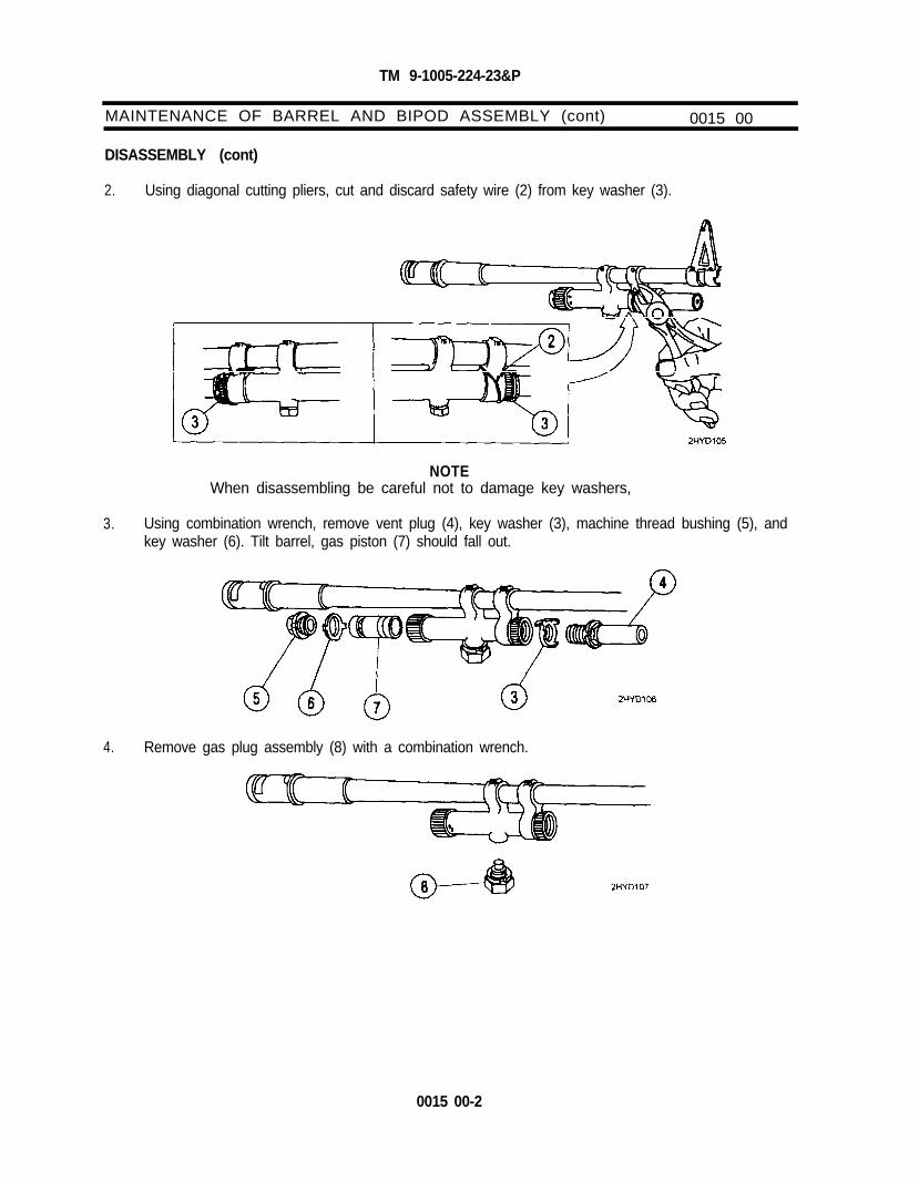
TM 9-1005-224-23&P
MAINTENANCE OF BARREL AND BIPOD ASSEMBLY (cont) 0015 00
DISASSEMBLY (cont)
2. Using diagonal cutting pliers, cut and discard safety wire (2) from key washer (3).
NOTEWhen disassembling be careful not to damage key washers,
3. Using combination wrench, remove vent plug (4), key washer (3), machine thread bushing (5), andkey washer (6). Tilt barrel, gas piston (7) should fall out.
4. Remove gas plug assembly (8) with a combination wrench.
0015 00-2

TM 9-1005-224-23&P
REPAIR
WARNINGDry cleaning solvent (SD) is flammable. Do not clean parts near anopen flame or in a smoking area. Dry cleaning solvent evaporatesquickly and has a drying effect on the skin. When used withoutprotective gloves, solvent may cause irritation to or cracking of the skin.
CAUTIONCare MUST be exercised to avoid getting lubricant or oil in the gascylinder when cleaning the barrel. Position the gas cylinder above thebarrel during cleaning. The gas cylinder components will be removedand cleaned only when inspection reveals that the piston will no longermove within the cylinder under its own weight when the barrel is tiltedend for end. If gas cylinder components are cleaned, wipe interior ofcylinder and piston dry before reassembly. After reassembly, check formovement of gas piston by manually tilting the barrel assembly. Rewirevent plug.
NOTEDo not dilute lubricant. Shake well before using.
Burrs or raised surfaces may be removed or smoothed using a fine gritsharpening stone. DO NOT change the tolerances of any component bystoning. Cracks, chips, dents, or gouges on components shall bereported to direct support maintenance for repair or replacement.
Cracks, chips, dents, or gouges on breech bolt locking surfaces candamage the barrel socket. Damage to barrel socket locking surfacescan damage the breech bolt. Notify direct support maintenance forreplacement or repair if either condition exists.
No abrasive materials will be used to clean the gas piston or the inside ofthe gas cylinder (i.e. green pads, steel wool or crocus cloth). Thereceiver brush will not be used to clean inside of gas cylinder.
1. The use of crocus cloth is restricted for external surfaces only.
CAUTIONIf solid film lubricant comes in contact with any moving or internal part,clean part with dry cleaning solvent.
2. Following manufacturers instructions for use, apply solid film lubricant to all external surfacesshowing wear and allow weapon to dry 12 hours before being used.
3. Repair by replacing safety wire, unserviceable key washers, and gas plug assembly.
0015 00-3

TM 9-1005-224-23&P
MAINTENANCE OF BARREL AND BIPOD ASSEMBLY (cont) 0015 00
REPAIR (cont)
NOTERestore gas cylinder assembly to a serviceable condition by performingthe following procedures,
4. Insert reamer (1) on screwdriver and reamer combination wrench all the way in the machine threadplug hole to make sure all carbon is removed.
5. Remove carbon from holes in gas cylinder (2) with reamer (1) and wipe carbon residue from gascylinder (2).
6. Remove carbon from holes in gas piston (3) with reamer (1) and wipe carbon residue from gaspiston (3).
0015 00-4

TM 9-1005-224-23&P
REASSEMBLY
1. Install gas piston (1) in gas cylinder (2). Make sure holes in gas piston (1) are facing rearward.
2. Install and tighten key washer (3) and machine thread bushing (4).
3. Install and tighten key washer (5) and vent plug (6).
4. Check location of locking tab. When tightened, the locking tab must be in the location shown.
0015 00-5

TM 9-1005-224-23&P
MAINTENANCE OF BARREL AND BIPOD ASSEMBLY (cont) 0015 00
REASSEMBLY (cont)
5. Tilt barrel and bipod assembly (7) up and down. Gas piston should click as it moves inside gascylinder (2). If click is not heard, disassemble, clean, and assemble again (refer to TM 9-1005-224-10).
6. Install and tighten gas plug assembly (8) with combination wrench. If the gas plug is the old typethat does not have a lock washer, safety wire the gas plug.
NOTEIf gas plug is the old type (without lock washer), safety wire the plug.
7. Secure key washer (5) to gas cylinder (2) with safety wire (9) to cylinder front mounting arm asshown, using double twist method.
END OF TASK
0015 00-6

TM 9-1005-224-23&P
MAINTENANCE OF COVER ASSEMBLY 0016 00
THIS TASK COVERS:Inspection, Disassembly, Repair, Reassembly
INITIAL SETUP
Maintenance LevelUnit
Applicable ConfigurationM60/M60D Machine Guns
Tools and Special ToolsSmall Arms Repairman Tool Kit
(SC 5180-95-CL-A07)
Troubleshooting ReferencesRefer to WP 0006 00
Materials/PartsBrush, cleaning, tool and parts
(item 1, WP 0082 00)Dry cleaning solvent (SD) (item 7, WP 0082 00)Gloves, rubber (item 8, WP 0082 00)Lacquer (item 9, WP 0082 00)Lubricant (as required)Rag, wiping (item 13, WP 0082 00)
ReferencesTM 9-1005-224-10
General Safety Instructions
WARNINGDry cleaning solvent (SD) is flammable. Do not clean parts near anopen flame or in a smoking area. Dry cleaning solvent evaporatesquickly and has drying effect on the skin. When used without protectivegloves, solvent may cause irritation to or cracking of the skin.
INSPECTION
1. Inspect cover assembly for broken, bent, worn, or missing parts.
2. Inspect cover assembly for proper cleaning and lubrication.
3. Rubber coating must not be gummy or retain finger impressions. Abrasions, cuts, gouges, andholes in rubber are acceptable. Loose bonding of rubber near cuts, etc., is acceptable providedcuts do not interfere with operator’s grip on weapon.
4. Visually inspect external surfaces for dull black finish.
DISASSEMBLY
1. Remove guide cotter pin (1) and straight shaft (2).
0016 00-1

TM 6-1005-224-23&P
MAINTENANCE OF COVER ASSEMBLY (cont) 0016 00
2. Push down and over to remove front (3) and rear (4) cartridge guides.
3. Pull back on feed cam retainer (5) with long nose pliers and lift out feed cam assembly (6).
4. Press in on spring lever clip (7) and lift out feed lever assembly (8).
5. Lift out helical torsion spring (9).
0016 00-2

TM 9-1005-224-23&P
6. Slide feed pawl assembly (10) in slot (11) and guide it toward feed lever stud (12). Remove feedpawl assembly (10).
REPAIR
1. Replace damaged helical torsion spring (10).
2. Clean powder-fouled parts with CLP/RBC and a brush. Wipe all parts clean and remove excessCLP/RBC with a wiping rag.
3. Apply a coating of lubricant on the lower surfaces and frame mating areas of feed pawl assembly (2).
4. Dampen wiping rag with lubricant and wipe each part before reassembling cover assembly (3).
0016 00-3

TM 9-1005-224-23&P
MAINTENANCE OF COVER ASSEMBLY (cont)
REPAIR (cont)
0016 00
5. Refinish exterior of all aluminum parts not having a dull black finish by painting with a blacklusterless lacquer (item 9, WP 0082 00).
6. Clean worn or flaking surfaces with crocus cloth. Wash thoroughly with dry cleaning solvent.
7. Following manufacturer's instructions for use, apply lacquer to all external aluminum surfacesshowing wear and allow to dry for appropriate length of time before being used.
REASSEMBLY
1. Place feed pawl assembly (1) in slot (2) near feed lever stud (3) and slide it into narrow leg of slot (2).
2. Place helical torsion spring (4) around feed lever stud (3) and hook one end of helical torsionspring (4) in slot (2).
0016 00-4

TM 9-1005-224-23&P
3. Position feed lever assembly (5) so slot (6) is aligned above projection (7) on feed pawl assembly (1).
4. Press spring lever clip (8) in feed lever assembly (5) and place on feed lever stud (3). Make surehelical torsion spring (4) rests against side of feed lever assembly (5).
5. Align feed cam assembly (9) with feed lever assembly (5) so cam stud (10) enters slot in the end offeed lever assembly (5). Align hole (11) over cover stud (12).
0016 00-5

TM 9-1005-224-23&P
MAINTENANCE OF COVER ASSEMBLY (cont) 0016 00
REASSEMBLY (cont)
6. Pull back on feed cam retainer (13) with long nose pliers and press down on feed cam assembly(9) to latch it.
7. Move feed pawl assembly (1) back and forth several times to check it for freedom of movement,Make sure feed pawl assembly (1) does not bind. If binding is present, notify direct supportmaintenance.
8. Install front (14) and rear (15) cartridge guides.slide out to align hole for straight shaft.
Press down on front and rear cartridge guides andSecure with straight shaft (16).
0016 00-6

TM 9-1005-224-23&P
9. Install guide cotter pin (17) on straight shaft (16) and bend prongs of guide retaining pin aroundstraight shaft so ends do not stick out.
END OF TASK
0016 00-7/0016 00-8 blank


TM 9-1005-224-23&P
MAINTENANCE OF TRAY AND HANGER ASSEMBLY ANDCARTRIDGE FEED TRAY ASSEMBLY (M60 ONLY)
THIS TASK COVERS:Disassembly, Repair, Reassembly
0017 00
INITIAL SETUP
Maintenance LevelUnit
Applicable ConfigurationM60 Machine Gun
Tools and Special ToolsSmall Arms Repairman Tool Kit
(SC 5180-95-CL-A07)
NOTEThe cartridge feed tray assembly is a subassembly of the tray andhanger assembly. Since the cartridge feed tray components cannot beremoved separately from the major components of the tray and hangerassembly, maintenance procedures are combined in this work package.
DISASSEMBLY
1. Slowly tap cartridge shaft (1) out part way with a hammer and 1/8-inch drive pin punch.Catch helical torsion spring (2) and cartridge retainer pawl (3) from underside of cartridge trayframe assembly (4).
2. Remove cartridge shaft (1) and separate magazine bandoleer hanger assembly (5) from cartridgetray frame assembly (4).
0017 00-1

TM 9-1005-224-23&P
MAINTENANCE OF TRAY AND HANGER ASSEMBLY ANDCARTRIDGE FEED TRAY ASSEMBLY (M60 ONLY)
REPAIR
0017 00
Repair by replacing all authorized components.
REASSEMBLY
1. Attach magazine bandoleer hanger assembly (1) to cartridge tray frame assembly (2), and insertcartridge shaft (3) in part way.
2. Insert cartridge retainer pawl (4) and helical torsion spring (5) as a unit from underside of cartridgetray frame assembly (2) and align helical torsion spring (5) with cartridge shaft.
3. Insert 1/8-inch drive pin punch in other side and work it through cartridge retainer pawl (4) andhelical torsion spring (5) to help keep all parts in line.
0017 00-2

TM 9-1005-224-23&P
4. Use hammer to tap cartridge shaft (3) and drive it through retainer pawl (4), helical torsionspring (5), magazine bandoleer hanger assembly (1) until it drives out drive pin punch. Flush bothends of cartridge shaft (3).
END OF TASK
0017 00-3/0017 00-4 blank


TM 9-1005-224-23&P
MAINTENANCE OF CARTRIDGE FEED TRAY ASSEMBLY (M60D ONLY) 0018 00
THIS TASK COVERS:Disassembly, Repair, Reassembly
INITIAL SETUP
Maintenance LevelUnit
Applicable ConfigurationM60D Machine Gun
Tools and Special ToolsSmall Arms Repairman Tool Kit
(SC 5180-95-CL-A07)
DISASSEMBLY
1. Slowly tap cartridge shaft (1) part way out with a hammer and 1/8 inch drive pin punch andremove one yoke roller (2), helical torsion spring (3), and cartridge retainer pawl (4) from undersideof cartridge tray frame assembly (5).
2. Remove cartridge shaft (1) and separate second yoke roller (2) from cartridge tray frameassembly (5).
REPAIR
Repair by replacing all authorized components.
0018 00-1

TM 9-1005-224-23&P
MAINTENANCE OF CARTRIDGE FEED TRAY ASSEMBLY (M60D ONLY) (cont) 0018 00
REASSEMBLY
1.
2.
3. Insert second yoke roller (6) in cartridge tray frame assembly (2). Insert 1/8-inch drive pin punch inother side and work it through cartridge retainer pawl (4) and helical torsion spring (5) to help keepall parts in line.
Attach one yoke roller (1) to cartridge tray frame assembly (2) and insert cartridge shaft (3) in partway.
Insert cartridge retainer pawl (4) and helical torsion spring (5) as a unit from underside of cartridgetray frame assembly (2) and align helical torsion spring (5) with cartridge shaft (3).
0018 00-2

TM 9-1005-224-23&P
4. Use hammer to tap cartridge shaft (3) and drive it through retainer pawl (4), helical torsionspring (5) until it drives out drive pin punch. Flush both ends of the cartridge shaft (3).
END OF TASK
0018 00-3/ 0018 00-4 blank


TM 9-1005-224-23&P
MAINTENANCE OF FOREARM ASSEMBLY (M60 ONLY) 0019 00
THIS TASK COVERS:Inspection, Disassembly, Repair, Reassembly
INITIAL SETUP
Maintenance LevelUnit
Applicable ConfigurationM60 Machine Gun
Materials/PartsCloth, abrasive (crocus) (item 5, WP 0082 00)Dry cleaning solvent (SD) (item 7, WP 0082 00)Gloves, rubber (item 8, WP 0082 00)Lubricant, solid film (item 10, WP 0082 00)
Tools and Special ToolsSmall Arms Repairman Tool Kit
(SC 5180-95-CL-A07)
General Safety Instructions
WARNINGBe careful when removing and installing spring-loaded components.Carelessness could cause injury.
Dry cleaning solvent (SD) is flammable. Do not clean parts near anopen flame or in a smoking area. Dry cleaning solvent evaporatesquickly and has a drying effect on the skin. When used withoutprotective gloves, solvent may cause irritation to or cracking of the skin.
INSPECTION
1. Inspect forearm assembly for broken, bent, or torn surfaces. If damaged, notify direct supportmaintenance.
2. Check to see if sling swivel is properly secured or missing parts.
DISASSEMBLY
1. Using flat tip screwdriver, remove assembled washer screws (1) and sling swivel (2) from the leftside of forearm assembly (3). Shake out plate spacer (4).
0019 00-1

TM 9-1005-224-23&P
MAINTENANCE OF FOREARM ASSEMBLY (M60 ONLY) 0019 00
DISASSEMBLY (cont)
2. Using slip joint pliers, pull up on back end of flat catch spring (5).
3. To remove headless shoulder pin (6), press forward on forward catch (7). Remove headlessshoulder pin (6).
NOTEIf headless shoulder pin does not fall out, push pin out using a bent wire.
REPAIR
1. Repair by replacing all authorized components.
CAUTIONKeep dry cleaning solvent and solid film lubricant from coming intocontact with rubber coated surface.
2. Clean rusted metal surfaces with crocus cloth. Wash thoroughly with dry cleaning solvent (SD).
3. Following manufacturers instructions for use, apply solid film lubricant to all external surfacesshowing wear and allow weapon to dry 12 hours before being used.
0019 00-2

TM 9-1005-224-23&P
REASSEMBLY
1. Insert assembled washer screws (1) in sling swivel (2). Position sling swivel (2) against left side offorearm assembly (3) so loop is on top and ends of assembled washer screws (1) are stickingthrough side of forearm assembly (3).
2. Position plate spacer (4) inside forearm assembly (3). Align holes in plate spacer (4) with threadedends of assembled washer screws (1). Using flat tip screwdriver, tighten assembled washerscrews (1).
3. Insert forearm catch (7), with notch forward, into bracket on bottom of forearm assembly. Installheadless shoulder pin (6) through catch and pull back on forearm catch. Install flat catch spring (5)by inserting long end into notch of rib. Push down on back of spring until it snaps in place.
END OF TASK
0019 00-3/0019 00-4 blank

TM 9-1005-224-23&P
LUBRICATION INSTRUCTIONS 0020 00
Weapons NOT in use or that are to be stored in the arms room for prolonged periods should have allinterior and exterior metal parts lubricated and a light film of lubricant applied to the interior of the gascylinder and the gas piston following cleaning and inspection. The use of lubricant will not eliminateperiodic cleaning and/or inspection to ensure that corrosion is not forming. Remove excess lubricant fromthe remainder of the weapon. Avoid lubricant contact with non-metallic surfaces.
Refer to TM 9-1005-224-10 for lubrication instructions.
0020 00-1/0020 00-2 blank

TM 9-1005-224-23&P
PREPARATION FOR STORAGE OR SHIPMENT 0021 00
ADMINISTRATIVE STORAGE
Refer to Chapter 3, WP 0046 00.
0021 00-1/0021 00-2 blank


TM 9-1005-224-23&P
CHAPTER 3
DIRECT SUPPORT
MAINTENANCE INSTRUCTIONS


TM 9-1005-224-23&P
REPAIR PARTS, SPECIAL TOOLS AND SUPPORT EQUIPMENT 0022 00
COMMON TOOLS AND EQUIPMENT
For authorized common tools and equipment refer to Modified Table of Organization and Equipment(MTOE) applicable to your unit.
SPECIAL TOOLS AND SUPPORT EQUIPMENT
Tools and Test equipment requirements are listed in WP 0048 00. Special tools and support equipmentare listed and illustrated in WP 0079 00 of this manual. Fabricated tools are listed and illustrated inWP 0083 00.
REPAIR PARTS
Repair parts are listed and illustrated in WP 0050 00 through WP 0079 00 of this manual.
0022 00-1/0022 00-2 blank


TM 9-1005-224-23&P
TROUBLESHOOTING 0023 00
TROUBLESHOOTING PROCEDURES
Refer to work package WP 0006 00 of this manual.
0023 00-1/0023 00-2 blank


TM 9-1005-224-23&P
MAINTENANCE PROCEDURES 0024 00
GENERAL
Without a gauge, or inspection criteria, to determine if any component part or assembly of a weapon hasexcessive wear and/or how deep of a crescent/half-moon appearance make the component/ assemblyunserviceable, the determining factors will have to remain as follows:
a. The functional/operational check with dummy cartridges.
b. The experience and judgmental expertise of the DS armorer and/or maintenance personnelto determine that a component, assembly or repair part needs replacement.
NOTEWhen a weapon is received by direct support with a maintenancerequest, all gaging requirements must be checked as a standardmaintenance procedure. In addition, the weapon must be inspected andany other deficiencies found will be repaired, or noted for repair, at theappropriate maintenance level. As a minimum requirement, for activeduty M60/M60D guns the headspace and gaging must be verifiedannually by direct support personnel. All Army Reserve and ArmyNational Guard M60/M60D machine guns must be inspected and gagedat least every other year. This requirement could be increased up to fourtimes a year or after each training cycle depending on usage factors.
If the M60/M60D machine gun has to go to direct support maintenancefor any repair, both barrel assemblies must be turned in with the weapon.
Burrs or raised surfaces may be removed or smoothed using a fine gritsharpening stone. DO NOT change the dimensions of any componentsby stoning. Cracks, chips, dents, or gouges on components shall bereported to the appropriate maintenance level for repair or replacement.
Cracks, chips, dents, or gouges on breech bolt locking surfaces candamage the barrel socket. Damage to barrel socket locking surfacescan damage the breech bolt.
0024 00-1/0024 00-2 blank

TM 9-1005-224-23&P
MAINTENANCE OF M60 MACHINE GUN 0025 00
THIS TASK COVERS:Disassembly, Repair, Test/Inspection, Reassembly
INITIAL SETUP
Maintenance LevelDirect Support
Applicable ConfigurationM60 Machine Gun
Tools and Special Tools (cont)Plain cylindrical plug gage (7458598)Small Arms Gage Kit MS (5910297)Small Arms Tool Kit (SC 4933-95-CL-A11)Test bolt gage (7799699)
Tools and Special ToolsCombination square (GGG-S-656or equivalent)
Dial indicating scale (AAA-S-133or equivalent)
Firing pin protrusion gage (7274754)Headspace gage (7274790)Machinist’s steel rule (GGG-R-791or equivalent)
Materials/PartsIdentification tag (item 15, WP 0082 00)Lacquer (item 9, WP 0082 00)Wire, Nonelectrical (MS20995C32)
Troubleshooting ReferencesRefer to WP 0006 00
ReferencesTM 9-1005-224-10
General Safety Instructions
CAUTIONThe ability to detect oil movement on or around the rivet head and/orbetween riveted components does not classify rivets as being loose, andis an unauthorized procedure.
NOTEThe disassembly/reassembly procedures in this paragraph are additionsto those described in organizational maintenance (WP 0007 00).
Before doing the trigger pull test for both weapons (M60/M60D), theweapons must be reassembled.
No stamping or etching is authorized. Use tags for identification.
DISASSEMBLY
WARNINGMake sure weapon is cleared and that there are no obstructions in thebarrel.
1. Field-strip (TM 9-1005-224-10) and perform organizational maintenance in accordance withWP 0007 00.
0025 00-1

TM 9-1005-224-23&P
MAINTENANCE OF M60 MACHINE GUN (cont) 0025 00
DISASSEMBLY (cont)
2. Remove rear sight (1) from receiver assembly (2).
REPAIR
1. Repair by replacing all authorized components.
2. Additional maintenance procedures for subassemblies are contained in the following workpackages:
Barrel and bipod assembly..Work Package
........................................................................... WP 0031 00Breech bolt assembly .................................................................................... WP 0028 00Cocking handle assembly .............................................................................. WP 0043 00Cover assembly ............................................................................................. WP 0034 00Forearm assembly (M60 only) ....................................................................... WP 0039 00Operating rod assembly ................................................................................. WP 0029 00Rear sight (M60 only) .................................................................................... WP 0040 00Gun receiver assembly .................................................................................. WP 0044 00Shoulder gun stock assembly (M60 only). ...................................................... WP 0027 00Trigger mechanism grip assembly (M60 only) ................................................ WP 0030 00
TEST/INSPECTION
NOTESmall arms gages will be inspected and certified annually. The gageswill not be used unless they are accompanied with the appropriate gagerecord.
LOOSE RECEIVER TEST
1. a. Check for loose receiver. Remove all major assemblies and internal components(WP 0007 00 and WP 0044 00).
0025 00-2

TM 9-1005-224-23&P
TEST/INSPECTION (cont)
LOOSE RECEIVER TEST (cont)
b. Clamp receiver assembly (1) securely in machinist’s vise equipped with jaw caps.
2. Place combination square (2) against receiver assembly (1). Combination square (2) should beparallel to receiver assembly (1) with the edge of its blade touching the side of receiver assembly(1).
3. Attach dial indicating scale (3) to rear of receiver assembly (1).
NOTEIn the following step, after obtaining 10 pounds of pressure on dialindicating scale, release pressure and do not move combination square.
4. Pull dial indicating scale (3) to 10 pounds of pressure and allow combination square (2) to movewith receiver assembly (1).
0025 00-3

TM 9-1005-224-23&P
MAINTENANCE OF M60 MACHINE GUN (cont) 0025 00
TEST/INSPECTION (cont)
LOOSE RECEIVER TEST (cont)
5. Attach dial indicating scale (3) on other side of receiver assembly (1) and pull to 10 pounds ofpressure. Butt machinist’s steelrule (4) against receiver assembly (1) while holding pressure.
6. Read distance between receiver assembly (1) and blade of combination square (2). Totalhorizontal movement should not exceed 3/32 (0.094) of an inch.
7. Remove dial indicating scale (3).
8. Move combination square (2) against receiver assembly (1), and attach dial indicating scale (3) tobottom of receiver assembly (1).
0025 00-4

TM 9-1005-224-23&P
9. Mark receiver assembly (1) at whole number increments for reference point.
10. Pull dial indicating scale (3) to 10 pounds of pressure and hold it. Mark a line on the blade ofcombination square (2), or on the rear of receiver assembly (1), with pencil.
11. Remove dial indicating scale (3).
12. Attach dial indicating scale (3) to upper side of receiver assembly (1), pull dial indicating scale (3) to10 pounds of pressure, and hold it.
13. Measure vertical movement by using scribe line as a reference and reading against combinationsquare (2). Total vertical movement should not exceed 3/32 (0.094) of an inch.
14. Remove dial indicating scale (3) from receiver assembly (1).
0025 00-5

TM 9-1005-224-23&P
MAINTENANCE OF M60 MACHINE GUN (cont) 0025 00
TEST/lNSPECTlON (cont)
LOOSE RECEIVER TEST (cont)
NOTEReceiver assemblies exceeding the maximum looseness tolerance of3/32 (0.094) of an inch vertically or horizontally will be judgedunserviceable. Receiver assemblies having tolerances of less than 3/32(0.094) of an inch in either direction will be judged serviceable.
15. Inspect receiver assembly (1) and weld areas (5, 6, and 7). Minute or full length cracks in weldsare considered serviceable providing they pass the looseness check of 3/32 (0.094) of an inch,Cracks in the base metal of the receiver assembly (1) are a reason to consider it unserviceable.
NOTESame procedures will be utilized when checking breech bolt and barrelfor proper preembarkation headspace.
16. Raise barrel muzzle up to about 30 to 45 degree angle so locking surface can be seen clearly.
17. Moderate to severe mutilation or chipping on either surface shall be cause for removing barrel fromservice.
0025 00-6

TM 9-1005-224-23&P
18. Lower barrel muzzle to about 30 to 45 degree angle so cam curved surfaces can be seen clearly.
19. Raised burr on cam cover shall be removed with a smooth half round file and crocus cloth.
20. Return bad to service if headspace check is within tolerance.
BREECH BOLT TEST
1. Disassemble bolt assembly.
2. Using a firing pin protrusion gage and plain cylindrical plug gage, test breech bolt assembly.
3. Push forward firing pin (8) and measure the exposed length with firing pin protrusion gage (9).Firing pin (8) should protrude a minimum of 0.035 inches to a maximum of 0.043 inches.
4. Push firing pin (8) rearward using plain cylindrical plug gage (10). The gage shall not enter thefiring pin hole. The body of breech bolt assembly (11) will be replaced if the hole is oversized.
002500-7

TM 9-1005-224-23&P
MAINTENANCE OF M60 MACHINE GUN (cont) 0025 00
TEST/lNSPECTlON (cont)
BREECH BOLT TEST (cont)
WARNINGThe breech bolt assembly used with the weapon will be the only oneused when checking headspace. New breech bolt assemblies or testbolt gages will not be used as a standard.
Do not intermix breech bolt assembly or barrel and bipod assemblywithout checking headspace requirements.
NOTEIf headspace is faulty, a test bolt gage is required to determine if thebarrel or breech bolt is defective. Use of a new breech bolt assembly isauthorized only in a contingency situation, where it becomes imperativefor deployment of the weapon or to put the weapon on-line, until a testbolt gage is available.
For annually verified headspace, both barrels (issue and spare) will bechecked.
5.
6.
Check breech bolt assembly and barrel and bipod assembly for proper headspace using aheadspace gage, a test bolt gage, or a new breech bolt assembly.
Insert headspace gage (12) in chamber of barrel and bipod assembly (13).
NOTELeading edge of breech bolt assembly locking lugs must not touch thelocking recess edge of barrel socket when rotated.
If breech bolt assembly locks in chamber of barrel and bipod assemblywith headspace gage installed, headspace is incorrect. The followingprocedures can be used to determine fault.
0025 00-8

TM 9-1005-224-23&P
7. Insert breech bolt assembly (11) in socket of barrel and bipod assembly (13), and turn breech boltassembly (11) with light finger pressure. Breech bolt assembly (11) should not close.
NOTEA new breech bolt assembly may be used if test bolt gage is notavailable.
8. Remove breech bolt assembly from socket of barrel and bipod assembly (13), and insert test boltgage (14) in chamber.
9. If test bolt gage (14) does not close, breech bolt assembly (11) is defective. If test bolt gagecloses, barrel and bipod assembly (13) is defective.
10. Remove test bolt gage (14) and headspace gage (12) from barrel and bipod assembly (13).
BARREL AND BIPOD TEST
NOTECheck the small arms gage kit before using it.
1. Test barrel and bipod assembly for barrel erosion with Small Arms Gage Kit M8 (15).
0025 00-9

TM 9-1005-224-23&P
MAINTENANCE OF M60 MACHINE GUN (cont) 0025 00
TEST/INSPECTION (cont)
BARREL AND BIPOD TEST (cont)
2. Check barrel erosion gage (16) by sliding collet (17) on gage tube (18) to reject line (19).
3. Slide wear check gage (20) on barrel erosion gage (16). A drag can be felt as barrel erosion gage(16) contacts wear check gage (20).
4. Remove wear check gage (20) and slide handle of barrel erosion gage (16) to serviceable range.
5. Insert gage tube (18) in chamber end of barrel and bipod assembly (13) until collet (17) restsagainst rear of chamber.
0025 00-10

TM 9-1005-224-23&P
NOTEIf barrel is replaced, remove ID tag, attach to new barrel.
The first mark (20) on barrel erosion gage (16) is a preembarkationmark. It applies to barrels on weapons scheduled for overseas shipmentonly.
6. Apply light finger pressure to end of handle on barrel erosion gage (16) and read scale againstcollet (17). Barrel is serviceable until reject line (19) enters collet (17).
7. Remove and store Small Arms Gage Kit M8.
REASSEMBLY
1. With windage knob toward left side of receiver, slide rear sight (1) on receiver assembly (2) andcenter it in groove.
2. Locate original stake marks (3) on receiver assembly (2) used to secure rear sight (1).
3. Stake new stake marks (4) in four different locations.
0025 00-11

TM 9-1005-224-23&P
MAINTENANCE OF M60 MACHINE GUN (cont)
TRIGGER PULL TEST
0025 00
CAUTIONDo not allow breech bolt to slam closed when the weapon is empty, asthis will cause damage to locking surfaces on the breech bolt or barrel.
NOTEBefore doing the trigger pull test for both weapons (M60/M60D), theweapons must be reassembled.
1. Position the weapon in a vertical position and hook trigger pull fixture (21) on trigger (22). The searshould not release with less than 6 pounds of weights attached. Carefully add weights (23), asnecessary, until sear releases. Total weight should not exceed 11.5 pounds.
2. When trigger pull is light, check for worn sear lug, worn sear notches on operating rod, or a weaksear spring. When trigger pull is excessive, check for burrs on the sear lug and on the searnotches of the operating rod. Check sear spring to see if it is kinked or obstructed.
3. Remove weights (23) and trigger pull fixture (21) after test.
END OF TASK
0025 00-12

TM 9-1005-224-23&P
MAINTENANCE OF M6OD MACHINE GUN 0026 00
THIS TASK COVERS:Disassembly, Test/Inspection, Repair, Reassembly
INITIAL SETUP
Maintenance LevelDirect Support
Applicable ConfigurationM60/M60D Machine Guns
Tools and Special ToolsAnvil assembly (Fig. 3 thru 8, WP 0083 00)Combination square (GGG-S-656
or equivalent)Dial indicating scale (AAA-S-133or equivalent)
Firing pin protrusion gage (7274754)Headspace gage (7274790)
General Safety Instructions
Tools and Special Tools (cont)Machinist’s steel rule (GGG-R-791or equivalent)
Plain cylindrical plug gage (7458598)Small Arms Gage Kit M8 (5910297)Small Arms Tool Kit (SC 4933-95-CL-A11)Test bolt gage (7799699)
Materials/PartsLubricant (as required)
ReferencesTM 9-1005-224-10
CAUTIONDo not allow breech bolt to slam closed when the weapon is empty, asthis will cause damage to the locking surfaces on the barrel socket andbreech bolt.
NOTEThe disassembly/reassembly procedures in this paragraph are inaddition to those described in organizational maintenance (WP 0008 00).
Before doing the trigger pull test for both weapons (M60/M60D), theweapons must be reassembled.
DISASSEMBLY
1. Remove cotter pin (1), headed straight pin (2), lock-release lever (3), and helical compressionspring (4).
0026 00-1

TM 9-1005-224-23&P
MAINTENANCE OF M6OD MACHINE GUN (cont) 0026 00
DISASSEMBLY (cont)
2. Remove cotter pin (5), headed straight pin (6) pawl (7), and helical compression spring (8).
3. Remove solid rivets (9) from magazine bracket (10) only if replacement is necessary.
NOTEDo not remove rear sight unless rear sight base is damaged.
4. Using 1/2-inch drift pin and hammer, drive rear sight (11) out of grooved area on receiver assembly (12).
0026 00-2

TM 9-1005-224-23&P
REPAIR
Repair by replacing all authorized components.
Additional maintenance procedures for subassemblies are contained in the following work packages:
Work Package
Barrel and bipod assembly............................................................................. WP 0031 00Breech bolt assembly .................................................................................... WP 0028 00Cocking handle assembly .............................................................................. WP 0043 00Cover assembly ............................................................................................. WP 0034 00Gun receiver assembly.. ................................................................................ WP 0044 00Operating rod assembly ................................................................................. WP 0029 00Rear sight (M60D only). ................................................................................. WP 0042 00
REASSEMBLY
1. Insert solid rivets (1) in magazine bracket (2) and through receiver assembly (3).
2. Insert fabricated anvil assembly (4) (Figure 3 thru 8, WP 0083 00) in receiver assembly (3) byplacing grooved plate (5) in left side rails of receiver assembly (3). Once anvil assembly (4) isproperly fitted in receiver assembly (3), push smooth surfaced plate (6) in receiver assembly (3).
0026 00-3

TM 9-1005-224-23&P
MAINTENANCE OF M6OD MACHINE GUN (cont)
REASSEMBLY (cont)
0026 00
3. Insert and secure back plate (7) in machinist’s vise equipped with jaw caps.
4. Position receiver assembly (3) atop back plate (7). Using a drive pin punch and hammer, tightensolid rivets (1). Pull out smooth surfaced plate (6) and remove anvil assembly (4).
5. Position helical compression spring (8) and pawl (9) in magazine bracket (2). Insert headedstraight pin (10) and secure with cotter pin (11).
0026 00-4

TM 9-1005-224-23&P
6. Position helical compression spring (12) and lock-release lever (13) in magazine bracket (2). Insertheaded straight pin (14) and secure with cotter pin (15).
7. Install and center rear sight (16) in grooved space on receiver assembly (3).
8. Look for old stake marks (17) and restake new stake marks (18) in a different location. Using acenter punch and hammer, stake receiver assembly to base of rear sight (16) in four places.
0026 00-5

TM 9-1005-224-23&P
MAINTENANCE OF M6OD MACHINE GUN (cont) 0026 00
TRIGGER PULL TEST
NOTETest and inspection procedures are the same for the M60 (WP 0025 00)and M60D machine guns, except for checking the trigger pull (listedbelow).
The weapon must be reassembled before doing trigger pull test.
1. Check trigger pull using two trigger pull fixtures and a dummy round.
2. Press in on “F’ to place small arms safety (1) in fire (F) position.
3. First pull cocking handle assembly (2) to the rear, and then push it forward.
4. Press in on “S” to place small arms safety (1) in safe (S) position.
5. Load dummy rounds on cartridge feed tray (see TM 9-1005-224-10).
0026 00-6

TM 9-1005-224-23&P
6. Attach one trigger pull fixture (3) to each of the triggers (4).position.
Place small arms safety (1) in fire (F)
7. Tilt the weapon about 35 to 40 degrees and carefully add weights (5) until sear releases breech boltassembly. The sear should not release with less than 10 pounds of weight, but should release withless than 20 pounds of weight.
8. Remove weights (5), trigger pull fixtures (3), and the dummy rounds.
END OF TASK
0026 00-7/0026 00-8 blank


TM 9-1005-224-23&P
MAINTENANCE OF SHOULDER GUN STOCK ASSEMBLY (M60 ONLY) 0027 00
THIS TASK COVERS:Repair
INITIAL SETUP
Maintenance Level Tools and Special Tools (cont)Direct Support Small Arms Tool Kit (SC 4933-95-CL-A11)
Applicable ConfigurationM60 Machine Gun
Materials/PartsLubricant, solid film (item 10, WP 0082 00)
REPAIR
1. Remove solid rivets (1) from shoulder gun stock (2) if repair or replacement is necessary.
NOTEIf shoulder gun stock has cracks or enlarged holes in original rivet area,repair using the following procedures. If cracks are not present, installand secure solid rivets (1) in shoulder gun stock (2).
2. Measure in 1/2 inch from solid rivet holes. Select a 1/8-inch diameter, 1/4 inch-long, rivet withcountersunk head. Following the instructions furnished with the riveter, install rivets with a handblind riveter. After blind head rivets are installed, touch up shiny rivet heads with solid filmlubricant.
END OF TASK
0027 00-1/ 0027 00-2 blank


TM 9-1005-224-23&P
MAINTENANCE OF BREECH BOLT ASSEMBLY 0028 00
THIS TASK COVERS:Repair, Test
INITIAL SETUP
Maintenance LevelDirect Support
Applicable ConfigurationM60/M60D Machine Guns
Tools and Special ToolsFiring pin protrusion gage (7274754)Plain cylindrical plug gage (7458598)Small Arms Tool Kit (SC 4933-95-CL-A11)
General Safety Instructions
WARNINGThe breech bolt assembly used in the weapon will be the only one usedto check the headspace.
Do not intermix the breech bolt assembly or barrel and bipod assemblywithout checking headspace requirements.
CAUTIONDo not allow breech bolt to slam closed when the weapon is empty, asthis will cause damage to the locking surfaces or the barrel socket andbreech bolt.
NOTEIf headspace is faulty, a new breech bolt or test bolt gage is required todetermine whether the barrel or breech bolt is defective.
REPAIR
Repair by replacing all authorized components or by stoning (see WP 0011 00).
NOTEBurrs or raised surfaces may be removed or smoothed using afine grit sharpening stone. DO NOT change the dimensions ofany components by stoning. Cracks, chips, dents, or gouges oncomponents shall be reported to the appropriate maintenancelevel for repair or replacement.
Cracks, chips, dents, or gouges on breech bolt locking surfacescan damage the barrel socket. Damage to barrel socket lockingsurfaces can damage the breech bolt.
0028 00-1

TM 9-1005-224-23&P
MAINTENANCE OF BREECH BOLT ASSEMBLY (cont) 0028 00
TEST
NOTESmall arms gages will be inspected and certified annually. The gageswill not be used unless they are accompanied with the appropriate gagerecord.
Perform BREECH BOLT TEST (see WP 0025 00).
END OF TASK
0028 00-2

TM 9-1005-224-23&P
MAINTENANCE OF OPERATING ROD ASSEMBLY 0029 00
THIS TASK COVERS:Disassembly, Repair, Reassembly
INITIAL SETUP
Maintenance Level Tools and Special ToolsDirect Support Small Arms Tool Kit (SC 4933-95-CL-A11)
Applicable ConfigurationM60/M60D Machine Guns
NOTEDisassembly, reassembly, and stoning procedures are covered inWP 0011 00.
DISASSEMBLY
Remove spring pin (1), headless straight pin (2), and yoke roller (3) from operating rod assembly (4).
REPAIR
Repair by replacing all authorized components.
REASSEMBLY
Insert yoke roller (3) in slot of operating rod (4). Insert headless straight pin (2) and spring pin (1).
END OF TASK
0029 00-1/0029 00-2 blank


TM 9-1005-224-23&P
MAINTENANCE OF TRIGGER MECHANISM GRIP ASSEMBLY (M60 ONLY) 0030 00
THIS TASK COVERS:Repair
INITIAL SETUP
Maintenance LevelDirect Support
Tools and Special ToolsSmall Arms Tool Kit (SC 4933-95-CL-A11)
Applicable ConfigurationM60 Machine Gun
NOTEDisassembly and reassembly of trigger mechanism grip assembly iscovered in WP 0013 00.
REPAIR
Repair by replacing all authorized components.
END OF TASK
0030 00-1/ 0030 00-2 blank


TM 9-1005-224-23&P
MAINTENANCE OF BARREL AND BIPOD ASSEMBLY 0031 00
THIS TASK COVERS:Disassembly, Repair, Reassembly, Test
INITIAL SETUP
Maintenance LevelDirect Support
Applicable ConfigurationM60/M60D Machine Guns
Tools and Special ToolsHeadspace gage (7274790)Small Arms Gage Kit M8 (5910297)Small Arms Tool Kit (SC 4933-95-CL-A11)Test bolt gage (7799699)
Materials/Parts (cont)Cloth, abrasive (crocus) (item 5, WP 0082 00)Dry cleaning solvent (item 7, WP 0082 00)Gloves, rubber (item 8, WP 0082 00)Lubricant (as required)Lubricant, solid film (item 10, WP 0082 00)Rag, wiping (item 13, WP 0082 00)
Troubleshooting ReferencesRefer to WP 0006 00
ReferencesTM 9-1005-224-10
General Safety Instructions
WARNINGThe breech bolt assembly used in the weapon will be the only one usedto check headspace.
Do not intermix the breech bolt assembly or barrel and bipod assemblywithout checking headspace requirements.
NOTEHeadspace will be gaged annually using appropriate gages.
If headspace is faulty, a new breech bolt or test bolt gage is required todetermine whether the barrel or breech bolt is defective.
DISASSEMBLY
1. Refer to WP 0015 00 for disassembly of the gas cylinder system.
2. Turn barrel and bipod assembly (1) upside down, and place it in a machinist’s vise equipped withvise jaw caps. Tighten vise just enough to hold barrel and bipod securely.

TM 9-1005-224-23&P
MAINTENANCE OF BARREL AND BIPOD ASSEMBLY (cont) 0031 00
DISASSEMBLY (cont)
3. Using a portable electric drill and 7/64-inch twist drill, drill off stake marks from both sides of flashsuppressor (2).
4. Using a drive pin punch, drive out headless straight pin (3) and discard.
5. Unscrew and remove flash suppressor (2) and machine gun bipod (4) from barrel (5). Removebarrel (5) from machinist’s vise.
0031 00-2

TM 9-1005-224-23&P
REPAIR
1.
2.
3.
4.
5.
WARNINGDry cleaning solvent (SD) is flammable. Do not clean parts near anopen flame or in a smoking area. Dry cleaning solvent evaporatesquickly and has a drying effect on the skin. When used withoutprotective gloves, solvent may cause irritation to or cracking of the skin.
NOTENo abrasive materials will be used to clean the gas piston or the inside ofthe gas cylinder (i.e., green pads, steel wool, or crocus cloth). Thereceiver brush will not be used to clean inside of gas cylinder.
Repair by replacing all authorized components,
CAUTIONKeep dry cleaning solvent and lubricant out of the gas cylinder.
The use of crocus cloth is restricted to external surfaces only.
Following manufacturer’s instructions for use, apply solid film lubricant to all external surfacesshowing wear and allow weapon to dry 12 hours before being used.
Clean and lubricate in accordance with TM 9-1005-224-10.
Additional maintenance procedures for subassemblies of the barrel and bipod assembly are listedin the following work packages:
Work PackageMachine gun bipod ......................................................................... WP 0032 00Machine gun legs ........................................................................... WP 0033 00
REASSEMBLY
NOTEWhen a new flash suppressor or barrel is used, it must be drilled for aheadless straight pin. Redrilling may be required on originally installedequipment if tolerances changed.
1. Install machine gun bipod (1) on end of barrel (2).
0031 00-3
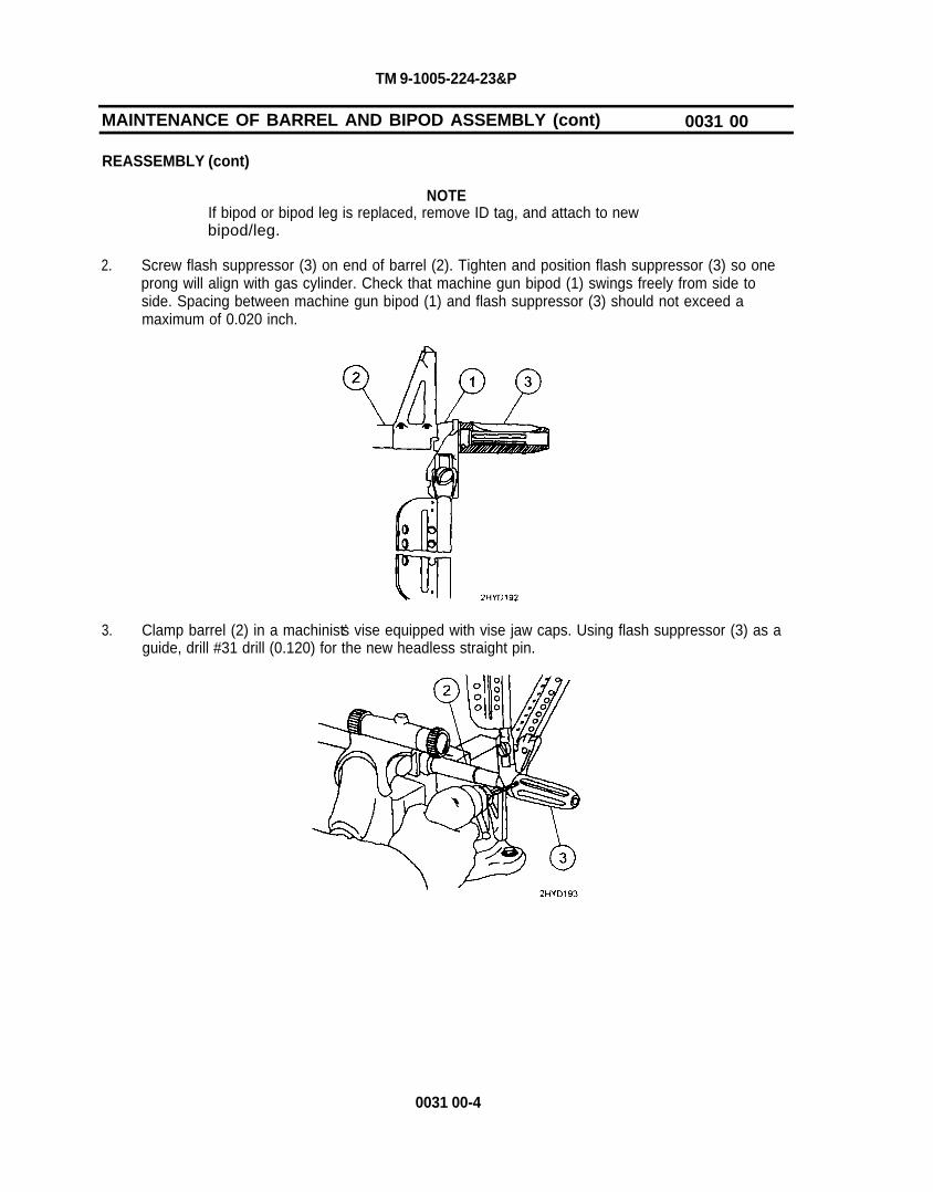
TM 9-1005-224-23&P
MAINTENANCE OF BARREL AND BIPOD ASSEMBLY (cont) 0031 00
REASSEMBLY (cont)
NOTEIf bipod or bipod leg is replaced, remove ID tag, and attach to newbipod/leg.
2. Screw flash suppressor (3) on end of barrel (2). Tighten and position flash suppressor (3) so oneprong will align with gas cylinder. Check that machine gun bipod (1) swings freely from side toside. Spacing between machine gun bipod (1) and flash suppressor (3) should not exceed amaximum of 0.020 inch.
3. Clamp barrel (2) in a machinist’s vise equipped with vise jaw caps. Using flash suppressor (3) as aguide, drill #31 drill (0.120) for the new headless straight pin.
0031 00-4

TM 9-1005-224-23&P
4. Drive headless straight pin (4) in hole (5), center the pin in the flash suppressor and stake to secureboth ends of headless straight pin (4). Loosen machinist’s vise and remove barrel and bipodassembly (6).
5. Clean rusted metal surfaces with crocus cloth. Wash thoroughly with dry cleaning solvent (SD).
CAUTIONMake sure solid film lubricant does not enter into the gas cylinder.
6. Following manufacturer’s instructions for use, apply solid film lubricant to all external surfacesshowing wear and allow weapon to dry 12 hours before being used.
7. Refer to WP 0015 00 for reassembly procedures for the gas cylinder assembly.
NOTEBipod legs must be open to work on the gas cylinder assembly.
0031 00-5

TM 9-1005-224-23&P
MAINTENANCE OF BARREL AND BIPOD ASSEMBLY (cont) 0031 00
TEST
WARNINGThe breech bolt assembly used in the weapon will be the only oneused to check headspace.
Do not intermix the breech bolt assembly or barrel and bipod assemblywithout checking headspace requirements.
NOTEHeadspace will be gaged annually using appropriate gages.
If headspace is faulty, a new breech bolt or test bolt gage is required todetermine whether the barrel or breech bolt is defective.
The test procedure below is in addition to those performed in BARRELAND BIPOD TEST (see WP 0025 00).
Visually check the barrel extension locking surfaces for cracks.
NOTEIf barrel is replaced, remove ID tag, and attach to new barrel.
1. Place the barrel and bipod assembly in a vise equipped with vise jaw caps. Tighten vise justenough to hold the assembly securely.
2. Attach a dial scale (1) to the foot (2) of leg assembly, depress the foot retainer button (3) fully andpull straight down. The leg assembly must extend and retract the full length of travel with amaximum force of 10 pounds. Repeat the procedure on the other leg.
END OF TASK
0031 00-6

TM 9-1005-224-23&P
MAINTENANCE OF MACHINE GUN BIPOD 0032 00
THIS TASK COVERS:Disassembly, Repair, Reassembly
INITIAL SETUP
Maintenance Level Tools and Special ToolsDirect Support Small Arms Tool Kit (SC 4933-95-CL-A11)
Applicable Configuration Materials/PartsM60/M60D Machine Guns Lubricant, solid film (item 10, WP 0082 00)
NOTEThe following procedures are performed when disassembling andreassembling both bipod legs.
DISASSEMBLY
1. Clamp end of bipod leg (1) in a machinist’s vise equipped with vise jaw caps.
2. Grind off end of shoulder screw (2) with a rotary grinder or hand file. Loosen machinist’s vise andremove bipod leg (1).
0032 00-1
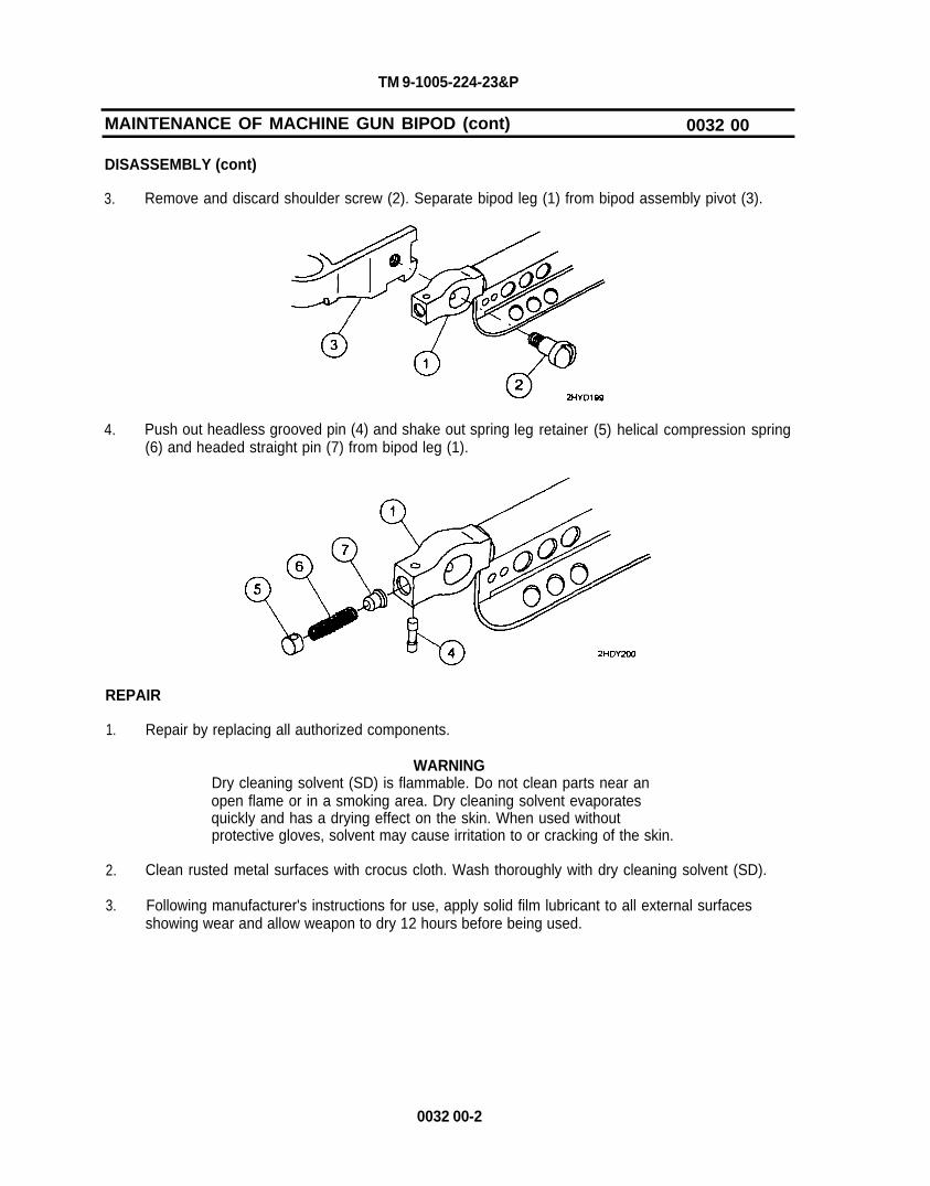
TM 9-1005-224-23&P
MAINTENANCE OF MACHINE GUN BIPOD (cont) 0032 00
DISASSEMBLY (cont)
3. Remove and discard shoulder screw (2). Separate bipod leg (1) from bipod assembly pivot (3).
4. Push out headless grooved pin (4) and shake out spring(6) and headed straight pin (7) from bipod leg (1).
leg retainer (5) helical compression spring
REPAIR
1. Repair by replacing all authorized components.
WARNINGDry cleaning solvent (SD) is flammable. Do not clean parts near anopen flame or in a smoking area. Dry cleaning solvent evaporatesquickly and has a drying effect on the skin. When used withoutprotective gloves, solvent may cause irritation to or cracking of the skin.
2. Clean rusted metal surfaces with crocus cloth. Wash thoroughly with dry cleaning solvent (SD).
3. Following manufacturer's instructions for use, apply solid film lubricant to all external surfacesshowing wear and allow weapon to dry 12 hours before being used.
0032 00-2

TM 9-1005-224-23&P
REASSEMBLV
1. Insert headed straight pin (1) and helical compression spring (2) in bipod leg (3).
2. Position spring leg retainer (4) so hole aligns with the hole in bipod leg (3). Install headlessgrooved pin (5).
3.3. Press in on headed straight pin (1), and insert new shoulder screw (6) in bipod leg (3).
4. Position bipod leg (3) against bipod assembly pivot (7) and tighten shoulder screw (6).
0032 00-3

TM 9-1005-224-23&P
MAINTENANCE OF MACHINE GUN BIPOD (cont) 0032 00
REASSEMBLY (cont)
5. Using a hammer and punch, stake shoulder screw (6) in two places.
END OF TASK
0032 00-4

TM 9-1005-224-23&P
MAINTENANCE OF MACHINE GUN LEGS 0033 00
THIS TASK COVERS:Disassembly, Repair, Reassembly
INITIAL SETUP
Maintenance LevelDirect Support
Applicable ConfigurationM60/M60D Machine Guns
Tools and Special ToolsSmall Arms Tool Kit (SC 4933-95-CL-A11)
DISASSEMBLY
NOTEIf foot of bipod leg rotates 360°, replace the entire leg assembly.
Remove peened end of solid rivets (1) and drive out rivets. Shake machine key (2) out of bipod leg (3).
REPAIR
Repair by replacing all authorized components.
REASSEMBLY
NOTEIf bipod or bipod leg is replaced, remove ID tag, and attach to newbipod/leg.
Insert machine key (2) in bipod leg (3). Install and secure solid rivets (1).
END OF TASK
0033 00-1/0033 00-2 blank


TM 9-1005-224-23&P
MAINTENANCE OF COVER ASSEMBLY 0034 00
THIS TASK COVERS:Disassembly, Repair, Reassembly
INITIAL SETUP
Maintenance LevelDirect Support
Tools and Special ToolsSmall Arms Tool Kit (SC 4933-95-CL-A11)
Applicable ConfigurationM60/M60D Machine Guns
DISASSEMBLY
Refer to WP 0016 00 for disassembly of cover assembly.
REPAIR
1. Repair by replacing all authorized components.
2. Additional maintenance procedures for subassemblies of the cover assembly are contained in thefollowing work packages:
Work PackagesCover housing assembly ................................................................. WP 0038 00 Feed cam assembly ................................................................ WP 0035 00 Feed lever assembly........................................................................... WP 0036 00 Feed pawl assembly.. . . . . . . . . . . . . . . . . . . . . . . . . . . . . . . . . . . . . . . . . . . . . . . . . . . . . . . WP 0037 00
REASSEMBLY
Refer to WP 0016 00 for reassembly of cover assembly.
END OF TASK
0034 00-1/0034 00-2 blank


TM 9-1005-224-23&P
MAINTENANCE OF FEED CAM ASSEMBLY 0035 00
THIS TASK COVERS:Disassembly, Repair, Reassembly
INITIAL SETUP
Maintenance Level Tools and Special ToolsDirect Support Small Arms Tool Kit (SC 4933-95-CL-A11)
Applicable ConfigurationM60/M60D Machine Guns
DISASSEMBLY
1. Push retainer plunger (1) back and hold it while feed cam retainer (2) is pushed out. Slowly releasepressure on retainer plunger (1).
2. Shake retainer plunger (1) and helical compression spring (3) from cam assembly (4).
0035 00-1

TM 9-1005-224-23&P
MAINTENANCE OF FEED CAM ASSEMBLY (cont) 0035 00
REPAIR
Repair by replacing all authorized components.
REASSEMBLY
1. Install helical compression spring (1) and retainer plunger (2) in cam assembly (3).
2. Press against retainer plunger (2) with a drive pin punch, and install feed cam retainer (4) in slot.Release pressure and withdraw drive pin punch.
END OF TASK
0035 00-2

TM 9-1005-224-23&P
MAINTENANCE OF FEED LEVER ASSEMBLY 0036 00
THIS TASK COVERS:Disassembly, Repair, Reassembly
INITIAL SETUP
Maintenance LevelDirect Support
Applicable ConfigurationM60/M60D Machine Guns
Tools and Special ToolsSmall Arms Tool Kit (SC 4933-95CL-A11)
DISASSEMBLY
Carefully use a screwdriver to free and separate end of spring lever clip (1) from feed lever (2).
2HYD211
REPAIR
Repair by replacing all authorized components.
REASSEMBLY
Attach spring lever clip (1) to feed lever (2), and slide them together until end of spring lever clip (1)enters slot in rear of feed lever (2).
2HYD212
END OF TASK
0036 00-1/0036 00-2 blank


TM 9-1005-224-23&P
MAINTENANCE OF FEED PAWL ASSEMBLY 0037 00
THIS TASK COVERS:Disassembly, Repair, Reassembly
INITIAL SETUP
Maintenance LevelDirect Support
Applicable ConfigurationM60/M60D Machine Guns
Tools and Special ToolsSmall Arms Tool Kit (SC 4933-95-CL-A11)
DISASSEMBLY
Push out shouldered shaft (1) and remove helical torsion spring (2). Separate chassis assembly (3) frompawl (4).
REPAIR
Repair by replacing all authorized components.
REASSEMBLY
1. Assemble chassis assembly (1) into center of pawl (2). Insert 1/16-inch drive pin punch into leftside of pawl (2) and through chassis assembly (1) slightly.
0037 00-1

TM 9-1005-224-23&P
MAINTENANCE OF FEED PAWL ASSEMBLY (cont) 0037 00
REASSEMBLY
2. Position helical compression spring (3) so the short tang is on the left side and presses againstfront side of pawl (2).
3. Turn helical compression spring (3) longest tang one half turn so end rest against chassisassembly.
4. Install shouldered shaft (4) into right side of chassis assembly (1) and tap it through to drive pinpunch out with the shouldered shaft (4).
END OF TASK
0037 00-2

TM 9-1005-224-23&P
MAINTENANCE OF COVER HOUSING ASSEMBLY 0038 00
THIS TASK COVERS:Disassembly, Repair, Reassembly
INITIAL SETUP
Maintenance Level Tools and Special ToolsDirect Support Small Arms Tool Kit (SC 4933-95-CL-A11)
Applicable ConfigurationM60/M60D Machine Guns
Materials/PartsLever Assembly, Latch (7269137)Rivet bucking tool (Fig. 9, WP 0083 00)Rivet heading tool (Fig. 10, WP 0083 00)
DISASSEMBLY
1. Remove solid rivets (1), and cam bumper assembly (2).
2. Using hand file with file handle, file of heads of solid rivets (3). Using 1/16-inch drive pin punch andhammer, drive out solid rivets (3) and remove cover shield (4).
0038 00-1

TM 9-1005-224-23&P
MAINTENANCE OF COVER HOUSING ASSEMBLY (cont) 0038 00
DISASSEMBLY (cont)
NOTEIf cheek pad is the only item requiring maintenance, do not disassemblethese items. Go to repair section below for alternate repair instructions.
3. Using a 1/8-inch twist drill and electric drill, drive punch end off of headed shoulder pins (5).Remove and discard headed shoulder pins (5). Lift out flat washers (6) and helical compressionsprings (7).
4. Using a 3/16-inch twist drill and an electric drill, drill end of latch lever assembly (8) to removepeened area. Remove and discard latch lever assembly (8). Remove cover latch (9) and helicaltorsion spring (10).
0038 00-2

TM 9-1005-224-23&P
5. Grind off heads of four solid rivets. Using a 1/16-inch punch, drive out solid rivets (11) andseparate cheek pad assembly (12) from cover frame assembly (13).
6. Remove headless straight pin (14) from cover frame assembly (13).
REPAIR
1. Repair by replacing all authorized components.
2. Place corner of cheek pad assembly (1) on a block of wood or steel, as shown. Using a 1/4-inchhand cold chisel and hammer, cut cheek pad assembly (1) along top edge of frame assembly backpast latch lever hole.
0038 00-3

TM 9-1005-224-23&P
MAINTENANCE OF COVER HOUSING ASSEMBLY (cont)
REPAIR (cont)
0038 00
3. Using slip joint pliers, bend corner of cheek pad assembly (1) back past latch lever hole.corner if possible and discard.
Break off
4. Wearing an industrial faceshield and using a utility grinding machine, grind off heads of four solidrivets (2).
5. Using a 1/16-inch drive pin punch and hammer, drive out four solid rivets (2) from cheek padassembly (1). Remove cheek pad assembly (1) and discard.
0038 00-4

TM 9-1005-224-23&P
6. Place new cheek pad on a solid surface, as shown. Using hammer and cold chisel, cut down toexisting hole of both sides to form a slot. Using hand file, remove all burrs and sharp edges fromthe slot area.
7. Slide cheek pad slotted area around lever shaft (3). Align rivet holes and insert one or two solidrivets (4).
8. Clamp fabricated rivet bucking tool (Fig. 9, WP 0083 00) in the machinist’s vise. Position rivethead into the concave recess. Position fabricated rivet heading tool on end of solid rivet. Usehammer to rivet all four rivets.
CAUTIONDo not attempt to touch up shiny metal in the slotted area with solid filmlubricant. The process can cause damage to the rubber coating.
0038 00-5

TM 9-1005-224-23&P
MAINTENANCE OF COVER HOUSING ASSEMBLY (cont) 0038 00
REASSEMBLY
1. Insert headless straight pin (1) through holes of cover frame assembly (2).
2. Insert helical compression spring (3) so long end of tangs is under headless straight in (1). Positioncover latch (4) so tang touches cross section of spring (3). Insert drive pin punch from curved sideof the cover frame assembly (2) and through the spring and cover latch (4).
3. Press on helical compression spring (3) in center of cover latch (4) with a flat tip screwdriver. Keeppressure on screwdriver and on helical compression spring (3).
0038 00-6

TM 9-1005-224-23&P
4. Insert new latch lever assembly (5) from the straight side of the cover. Slowly guide the latch leverassembly (5) through spring and gradually work the punch out of other side.
5. Using ballpeen end of hammer, peen end of latch lever assembly (5) in cover frameassembly (2).
NOTENew cheek pads will have a slot cut for the latch lever assembly.Unmodified cheek pad may be issued and will require modification usingsteps 6 through 8 under REPAIR.
6. Assemble shoulder pins (6), flat washers (7), and helical compression springs (8) and install incover frame assembly (2). Using ballpeen end of hammer, peen ends of headed shoulder pins (6).Ensure that shoulder pins are tight (no movement). Repeat procedures for other pin.
0038 00-7

TM 9-1005-224-23&P
MAINTENANCE OF COVER HOUSING ASSEMBLY (cont) 0038 00
REASSEMBLY (cont)
7. Install cover shield (9) on cover frame assembly (2), align holes, and install solid rivets (10). Do notinstall solid rivets in holes (11). Secure solid rivets (10).
8. Install cam bumper assembly (12) and align holes. Install and secure solid rivets (13).
END OF TASK
0038 00-8

TM 9-1005-224-23&P
MAINTENANCE OF FOREARM ASSEMBLY (M60 ONLY) 0039 00
THIS TASK COVERS:Repair
INITIAL SETUP
Maintenance LevelDirect Support
Applicable ConfigurationM60 Machine Gun
Tools and Special ToolsDrilling fixture assembly (Fig. 13, WP 0083 00)No. 30 twist drill (GGG-D-751)Small Arms Tool Kit (SC 4933-95-CL-A11)
Materials/PartsForearm assembly rib (Fig. 2, WP 0083 00)
REPAIR
1. Repair forearm assembly by replacing broken forearm rib. Remove flat catch spring (1).
2. Straighten damaged rib (2) as much as possible. Return damaged metal to its originalconfiguration.
0039 00-1

TM 9-1005-224-23&P
MAINTENANCE OF FOREARM ASSEMBLY (M60 ONLY)
REPAIR (cont)
0039 00
3. Use 1/8-inch diameter twist drill and drilling fixture assembly (3) as a guide and drill two holes in thedamaged rib.
4. Place repair rib (4) (Fig. 2, WP 0083 00) on the side nearest to the catch of damaged rib.
5. Align drilled holes in repair rib (4) with holes in damaged rib (2). Install two rivets using blind headriveter. Make sure notch area (5) is not covered. Make sure curved portion (6) of repair rib (4)does not stick above damaged rib (2). If curved portion (6) is higher than repaired rib (2), use handfile to file off excess repair rib (4).
0039 00-2

TM 9-1005-224-23&P
6 . Reinstall flat catch spring (1).
END OF TASK
0039 00-3/0039 00-4 blank


TM 9-1005-224-23&P
MAINTENANCE OF REAR SIGHT (M60 ONLY) 0040 00
THIS TASK COVERS:Disassembly, Repair, Reassembly
INITIAL SETUP
Maintenance LevelDirect Support
Applicable ConfigurationM60 Machine Gun
Tools and Special ToolsSmall Arms Tool Kit (SC 4933-95-CL-A11)
DISASSEMBLY
NOTERemove rear sight from receiver only if required to perform repair.
1. Turn adjustment knob (1) so view of tubular rivet (2) is unobstructed. Place rear sight in vise.Remove tubular rivet (2) and lateral adjustment slide (3). Discard tubular rivet (2).
0040 00-1

TM 9-1005-224-23&P
MAINTENANCE OF REAR SIGHT (M60 ONLY) 0040 00
DISASSEMBLY (cont)
CAUTIONTwo bearing balls and two helical compression springs are betweenleaf assembly, and base and lateral knob assembly. Separate carefullyto prevent loss of bearing balls.
2. Screw headless shoulder pin (4) out of adjustment knob (1) and remove it while applying slightpressure on leaf assembly (5). Remove leaf assembly (5) bearing balls (6) and helicalcompression springs (7) from base and lateral knob assembly (8).
REPAIR
1. Repair by replacing all authorized components.
2. Additional maintenance procedures for subassemblies of the rear sight assembly are contained inthe following Work Package:
Work PackageLeaf assembly . . . . . . . . . . . . . . . . . . . . . . . . . . . . . . . . . . . . . . . . . . . . . . . . . . . . . . . . . . . . . WP 0041 00
REASSEMBLY
1. Insert helical compression springs (1) in holes of base and lateral knob assembly (2). Place onebearing ball (3) on each helical compression spring (1).
0040 00-2

TM 9-1005-224-23&P
2. Carefully position leaf assembly (4) on base and lateral knob assembly (2), and slide headlessshoulder pin (5) in center of adjustment knob (6). Screw headless shoulder pin (5) into adjustmentknob (6) until leaf assembly (4) comes in contact with the inside edge of base and lateral knobassembly (2).
NOTEWhen a new headless shoulder pin is used, drill a hole in the headlessshoulder pin with a 5/64-inch twist drill. The hole in the lateraladjustment slide must be used as a guide and must be flush with the endof the headless shoulder pin.
3. Slide lateral adjustment slide (7) on end of headless shoulder pin(s) with lateral adjustment slidehole near end of headless shoulder pin (5).
0040 00-3
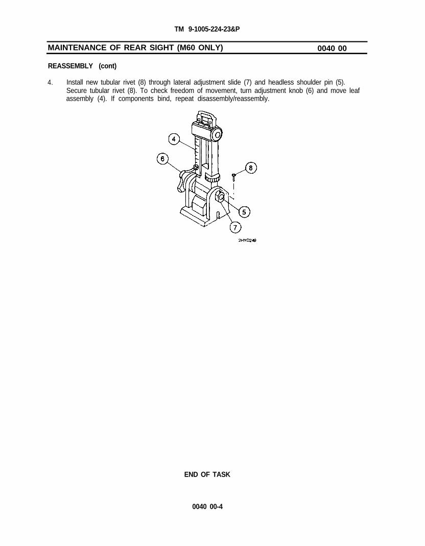
TM 9-1005-224-23&P
MAINTENANCE OF REAR SIGHT (M60 ONLY) 0040 00
REASSEMBLY (cont)
4. Install new tubular rivet (8) through lateral adjustment slide (7) and headless shoulder pin (5).Secure tubular rivet (8). To check freedom of movement, turn adjustment knob (6) and move leafassembly (4). If components bind, repeat disassembly/reassembly.
END OF TASK
0040 00-4

TM 9-1005-224-23&P
MAINTENANCE OF LEAF ASSEMBLY (M60 ONLY) 0041 00
THIS TASK COVERS:Disassembly, Repair, Reassembly
INITIAL SETUP
Maintenance LevelDirect Support
Applicable ConfigurationM60 Machine Gun
Tools and Special ToolsSmall Arms Tool Kit (SC 4933-95-CL-A11)
DISASSEMBLY
1. Using a drill, remove expanded point from machine screw (1) and peened end of tubular rivet (2).Remove and discard machine screw (1) and tubular rivet (2). Remove elevation scale (3).
NOTELeaf frame cap may be under spring tension from helical compressionspring mounted at the bottom of elevating screw.
2. Drill out peened end of solid rivet (4). Remove solid rivet (4) and leaf frame cap (5).
0041 00-1

TM 9-1005-224-23&P
MAINTENANCE OF LEAF ASSEMBLY (M60 ONLY) (cont) 0041 00
DISASSEMBLY (cont)
3. Press in on slide release assembly (6) and raise sight slide (7) while holding your hand over top ofrear sight leaf (8). Remove slide release assembly (6), helical compression spring (9), and sightslide (7) from rear sight leaf (8).
4. Remove elevation screw (10), elevating knob (11), bearing ball (12), and helical compressionsprings (13 and 14) from rear sight leaf (8).
REPAIR
Repair by replacing all authorized components.
0041 00-2

TM 9-1005-224-23&P
REASSEMBLY
1. Position elevation scale (1) on rear sight leaf (2), align holes, and install new machine screw (3).
2. Install helical compression springs (4 and 5), bearing ball (6), elevating knob (7), and insertelevation screw (8) from top of rear sight leaf (2).
3. Insert helical compression spring (9) and slide release assembly (10) in sight slide (11). Press inon slide release assembly (10) and slide rear sight leaf (2) through sight slide (11).
0041 00-3
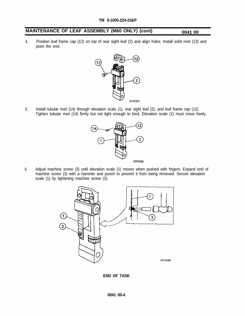
TM 9-1005-224-23&P
MAINTENANCE OF LEAF ASSEMBLY (M60 ONLY) (cont) 0041 00
4. Position leaf frame cap (12) on top of rear sight leaf (2) and align holes. Install solid rivet (13) andpeen the end.
5. Install tubular rivet (14) through elevation scale (1), rear sight leaf (2), and leaf frame cap (12).Tighten tubular rivet (14) firmly but not tight enough to bind. Elevation scale (1) must move freely.
6. Adjust machine screw (3) until elevation scale (1) moves when pushed with fingers. Expand end ofmachine screw (3) with a hammer and punch to prevent it from being removed. Secure elevationscale (1) by tightening machine screw (3).
END OF TASK
0041 00-4

TM 9-1005-224-23&P
MAINTENANCE OF REAR SIGHT (M60D ONLY) 0042 00
THIS TASK COVERS:Inspection, Disassembly, Repair, Reassembly
INITIAL SETUP
Maintenance LevelDirect Support
Applicable ConfigurationM60D Machine Gun
Materials/PartsCloth, abrasive (crocus) (item 5, WP 0082 00)Dry cleaning solvent (SD) (item 7, WP 0082 00)Gloves, rubber (item 8, WP 0082 00)Lubricant, solid film (item 10, WP 0082 00)
Tools and Special ToolsSmall Arms Tool Kit (SC 4933-95-CL-A11)
General Safety Instructions
WARNINGBe careful when removing and installing spring-loaded components.Carelessness could cause injury.
INSPECTION
1. Inspect sight ring for breaks, bends, or cracks.
2. Check to see if sight ring remains in both upright and folded positions when under spring tension.
DISASSEMBLY
Using a 3/32-inch drive pin punch and hammer, fold sight ring (1) down flat and remove spring pin (2).Using an open end adjustable wrench and flat tip screwdriver, remove hexagon self-locking nut (3). Applyslight pressure on sight ring (1) and remove rear sight retainer (4), bearing ball (5), and helicalcompression spring (6) from rear sight base (7).
NOTEAfter several disassemblies, a self-locking nut can lose its self-lockingfeature. If a self-locking nut works loose during operation, replace it.
0042 00-1

TM 9-1005-224-23&P
MAINTENANCE OF REAR SIGHT (M60D ONLY) (cont)
REPAIR
0042 00
WARNINGDry cleaning solvent (SD) is flammable. Do not clean parts near anopen flame or in a smoking area. Dry cleaning solvent evaporatesquickly and has a drying effect on the skin. When used withoutprotective gloves, solvent may cause irritation to or cracking of the skin,
1. Repair by replacing all authorized parts.
2. Clean rusted metal surfaces with crocus cloth. Wash thoroughly with dry cleaning solvent.
CAUTIONIf solid film lubricant comes in contact with any moving or internal part,clean part with dry cleaning solvent.
3. Following manufacturer’s instructions for use, apply solid film lubricant to all external metal surfacesshowing wear and allow weapon to dry 12 hours before being used.
REASSEMBLY
1. Place helical compression spring (1) in hole of rear sight base (2). Place bearing ball (3) on helicalcompression spring (1).
2. Position sight ring (4) on top of bearing ball (3) and rear sight base (2). Press down on rear sightand insert rear sight retainer (5) from the right side (largest hole).
3. Install hexagon self-locking nut (6) on end of rear sight retainer (5).
4. Using an open end adjustable wrench and flat tip screwdriver, center sight ring (4) so pin hole (7)aligns with groove (8) of rear sight retainer (5).
5. Using 1/8-inch drive pin punch and hammer, install spring pin (9).
END OF TASK
0042 00-2

TM 9-1005-224-23&P
MAINTENANCE OF COCKING HANDLE ASSEMBLY 0043 00
THIS TASK COVERS:Disassembly, Repair, Reassembly
INITIAL SETUP
Maintenance Level Tools and Special ToolsDirect Support Small Arms Tool Kit (SC 4933-95-CL-A11)
Applicable ConfigurationM60/M60D Machine Guns
DISASSEMBLY
Compress and hold helical compression spring (1). Remove cocking handle retainer (2) and helicalcompression spring (1) from cocking handle slide assembly (3).
REPAIR
Repair by replacing all authorized components.
REASSEMBLY
Insert helical compression spring (1) in cocking handle slide assembly (3). Press helical compressionspring (1) and slide cocking handle retainer (2) in cocking handle slide assembly (3). Release pressureon helical compression spring (1).
END OF TASK
0043 00-1/0043 00-2 blank


TM 9-1005-224-23&P
MAINTENANCE OF GUN RECEIVER ASSEMBLY 0044 00
THIS TASK COVERS:Disassembly, Repair, Reassembly, Test/Inspection
INITIAL SETUP
Maintenance LevelDirect Support
Applicable ConfigurationM60/M60D Machine Guns
Tools and Special Tools (cont)Dial indicating scale (AAA-S-133 or equivalent)Machinist’s steel rule (GGG-R-791 or
equivalent)Small Arms Tool Kit (SC 4933-95-CL-A11)
Tools and Special ToolsAnvil bucking bar (Fig. 1, WP 0083 00)Combination square (GGG-S-656or equivalent)
DISASSEMBLY
1. Remove staked metal from headless straight pin (1) and remove headless straight pin (1).
2. Remove staked metal from headed straight pins (2). Remove and discard headed straight pins (2).Remove headless straight pin (3).
0044 00-1

TM 9-1005-224-23&P
MAINTENANCE OF GUN RECEIVER ASSEMBLY (cont) 0044 00
DISASSEMBLY (cont)
3. Carefully drill out and discard solid rivets (4). Remove mounting plate (5).
4. Drill out and discard countersunk solid rivets (6). Do not remove bridge (7) from receiver assembly (8).
REPAIR
Repair by replacing all authorized components.
REASSEMBLY
1. Insert and tighten countersunk solid rivets (1) with a anvil bucking bar (2) by sliding the anvilbucking bar in rear of receiver assembly (3) near bridge (4). Make sure countersunk solid rivets donot protrude more than 0.010 of an inch inside or 0.005 of an inch outside, and peen countersunksolid rivets.
0044 00-2
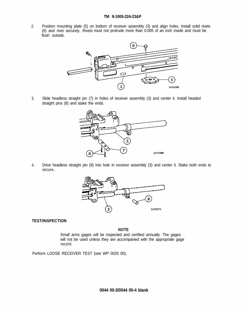
TM 9-1005-224-23&P
2. Position mounting plate (5) on bottom of receiver assembly (3) and align holes. Install solid rivets(6) and rivet securely. Rivets must not protrude more than 0.005 of an inch inside and must beflush outside.
3. Slide headless straight pin (7) in holes of receiver assembly (3) and center it. Install headedstraight pins (8) and stake the ends.
4. Drive headless straight pin (9) into hole in receiver assembly (3) and center it. Stake both ends tosecure.
TEST/INSPECTION
NOTESmall arms gages will be inspected and certified annually. The gageswill not be used unless they are accompanied with the appropriate gagerecord.
Perform LOOSE RECEIVER TEST (see WP 0025 00).
0044 00-3/0044 00-4 blank


TM 9-1005-224-23&P
PREEMBARKATION INSPECTION OF MATERIEL INUNITS ALERTED FOR OVERSEAS MOVEMENT 0045 00
GENERAL
This section provides special instructions for direct support personnel inspecting materiel in alerted unitsscheduled for overseas duty. Inspection is for:
a) Determining serviceability.b) Recognizing conditions that would cause failure.c) Assuring proper maintenance at prescribed level.d) Determining the ability of a unit to accomplish its maintenance and supply mission.
INSPECTION PROCEDURES
WARNINGBefore starting an inspection, be sure to clear the weapon. DO NOTactuate the trigger until the weapon has been cleared. Inspect thechamber to make sure that it is empty and that no ammunition is inposition to be introduced.
a. Exercise judgment regarding degree of inspection of integral parts within assemblies.
b. Refer to TB 9-1000-247-34 and specific inspection criteria listed below.
(1)
(2)
(3)
(4)
(5)
(6)
(7)
(8)
(9)
Check headspace using headspace gage 7274786 in place of head space gage 7274790(see WP 0025 00 for procedures).
Check trigger pull, WP 0025 00 for the M60 machine gun and WP 0026 00 for the M60Dmachine gun.
Check barrel for wear using a barrel erosion gage 7319994 (WP 0025 00).
Check firing pin protrusion using firing pin protrusion gage 7274754 (WP 0025 00).
Check firing pin hole using plain cylindrical plug gage 7458598 (WP 0025 00).
Measure operating rod helical compression spring. Spring must be a minimum of23 1/4 inches long.
Check sear cocking surface for roundness. Cocking surface must not be rounded more than3/64 of an inch on top rear corner.
Test receiver for looseness using procedures and equipment listed in WP 0025 00.
Make sure that the proper flat leaf spring is available for the proper model (WP 0005 00).
0045 00-1/0045 00-2 blank


TM 9-1005-224-23&P
PREPARATION FOR STORAGE OR SHIPMENT 0046 00
SECURITY
Security of the M60 or M60D machine gun is as defined in AR 190-11 and AR 190-13. Weapons will bestored in suitable containers to prevent theft, and as stated by the above security regulations. Thestorage area must be covered and as moisture-free as possible.
CLEANING AND PRESERVATION
1.
2.
3.
4.
Disassemble the M60 or M60D machine gun as necessary to accomplish cleaning and lubrication.
CAUTIONAvoid contaminating the gas cylinder with lubricants.
Clean all metallic surfaces of the M60 and M60D machine gun and Bll items with lubricating oiland dry with clean, dry wiping rags (item 13, WP 0082 00). Clean nonmetallic surfaces with clean,dry wiping rags.
Preserve all metallic surfaces with lubricating.
Reassemble weapon except for barrel assembly.
0046 00-1/0046 00-2 blank


TM 9-1005-224-23&P
APPENDIX A
REFERENCES


TM 9-1005-224-23&P
REFERENCES 0047 00
PUBLICATION INDEX
Consult the following publications indexes frequently for the latest changes or revisions of references andfor new publications relating to materiel covered in this manual.
ARMY REGULATIONS
AR 190-11 . . . . . . . . . . . . . . . . . . . . . . . . . . . . . . . . . . . . . . . . . . . . . Physical Security of Arms, Ammunition and Explosives
AR 190-13 . . . . . . . . . . . . . . . . . . . . . . . . . . . . . . . . . . . . . . . . . . . . . The Army Physical Security Program
DEPARTMENT OF ARMY PAMPHLETS
DA PAM 25-30 . . . . . . . . . .. . . . . . . . . . . . . . . . . . . . . . . Consolidated Index of Army Publications and Blank Forms
DA PAM 738-750 . . . . . . . . . . . . . . . . . . . . . . . . . . . . . .The Army Maintenance Management System (TAMMS)
RELATED PUBLICATIONS
DOD 4160.21-M-1 . . . . . . . . . . . . . . . . . . . . . . . . . . . Defense Demilitarization Manual
FIELD MANUALS
FM 21-30 . . . . . . . . . . . . . . . . . . . . . . . . . . . . . . . . . .Military Symbols
FM 23-67 . . . . . . . . . . . . . . . . . . . . . . . . . . . . . . . . . . . . Machine Gun, 7.62-MM, M60
SUPPLY BULLETINS
SB 708-41/42 . . . . . . . . . . . . . . . . . . . . . . . . . . . . . Federal Supply Codes for Manufactures: United Statesand Canada
SUPPLY CATALOGS
SC 4933-95-CL-A11. . . . . . . . . . . . . . . . . . . . . . . . . . Tool Kit, Small Arms: Field Maintenance, Post, Campand Station
SC 5180-95-CL-A07 . . . . . . . . . . . . . . . . . . . . . . Tool Kit, Small Arms Repairman
TECHNICAL BULLETINS
TB 9-1000-247-34 . . . . . . . . . . . . . . . . . . . . . . . . . . . . Standards for Overseas Shipment of Small Arms, AircraftArmament, Towed Howitzers, Mortars, Recoilless Rifles, RocketLaunchers, and Associated Fire Control Equipment
TECHNICAL MANUALS
TM 9-1005-224-10 . . . . . . . . . . . . . . . . . . . . . . . . . . . . . . . Operator’s Manual - M60/M60 D Machine Guns
TM 9-4933-208-34 . . . . . . . . . . . . . . . . . . . . . . . . . . . . . . . . . Kits, Barrel Erosion Gage, M8 and M6A1
0047 00-1

TM 9-1005-224-23&P
REFERENCES (cont) 0047 00
TECHNICAL MANUALS (cont)
TM 750-244-7 . . . . . . . . . . . . . . . . . . . . . Procedures for Destruction of Equipment in Federal SupplyClassification 1000, 1015, 1010, 1015, 1020, 1025, 1030, 1055,1090, and 1095 to Prevent Enemy Use
TM 9-1005-245-13&P. . . . . . . . . . . . . . . . . . . . . . . Operator’s, Unit, and Direct Support Maintenance Manual withRepair Parts and Special Tools List (RPSTL) for Machine GunMounts and Combinations for Tactical/Armored Vehicles andGround Mounting
AIR FORCE MANUALS
AFM 36-2227, Vol. 1 . . . . . . . . . . . . . . . . . Combat Arms Training Management and Range Operation
0047 00-2

TM 9-1005-224-23&P
APPENDIX B
MAINTENANCE ALLOCATION CHART


TM 9-1005-224-23&P
MAINTENANCE ALLOCATION CHART 0048 00
INTRODUCTION
This introduction provides a general explanation of all maintenance and repair functions authorizedat various maintenance levels under the standard Army Maintenance System concept.
The Maintenance Allocation Chart (MAC) immediately following the introduction designates overallauthority and responsibility for the performance of maintenance functions on the identified end item orcomponent, The application of the maintenance functions to the end item or component shall beconsistent with the capacities and capabilities of the designated maintenance levels, which are shown onthe MAC in column (4) as:
Unit .............................. Includes two subcolumns, C (operator/crew) and O (unit) maintenance
Direct Support . . . . . . . . . . . . . Includes an F subcolumn
General Support . . . . . . . . . . . Includes a H subcolumn
Depot . . . . . . . . . . . . . . . . . . . . . . Includes a D subcolumn
The tools and test equipment requirements (immediately following the MAC) list the tools and testequipment (both special tools and common tool sets) required for each maintenance function asreferenced from the MAC.
The remarks (immediately following the tools and test equipment requirements) contain supplementalinstructions and explanatory notes for a particular maintenance function.
MAINTENANCE FUNCTIONS
Maintenance functions will be limited to and defined as follows:
1.
2.
3.
4.
5.
Inspect. To determine the serviceability of an item by comparing its physical, mechanical, and/orelectrical characteristics with established standards through examination (e.g., by sight, sound, orfeel). This includes scheduled inspection and gagings and evaluation of cannon tubes.
Test. To verify serviceability by measuring the mechanical pneumatic, hydraulic, or electricalcharacteristics of an item and comparing those characteristics with prescribed standards on ascheduled basis, e. g., load testing of lift devices and hydrostatic testing of pressure hoses.
Service. Operations required periodically to keep an item in proper operating condition, e.g., toclean (includes decontaminate, when required), to preserve, to drain, to paint, or to replenish fuel,lubricates, chemical fluids, or gases. This includes scheduled exercising and purging of recoilmechanisms.
Adjust. To maintain or regulate, within prescribed limits, by bringing in proper position, or bysetting the operating characteristics to specified parameters.
Align. To adjust specified variable elements of an item to bring about optimum or desiredperformance.
0048 00-1

TM 9-1005-224-23&P
MAINTENANCE ALLOCATION CHART (cont) 0048 00
MAINTENANCE FUNCTIONS (cont)
6. Calibrate. To determine and cause corrections to be made or to be adjusted on instruments oftest, measuring and diagnostic equipment used in precision measurement. Consist of comparisonsof two instruments, one of which is a certified standard of known accuracy, to detect and adjust anydiscrepancy in the accuracy of the instrument being compared.
7. Remove/Install. To remove and install the same item when required to perform service or othermaintenance functions. Install may be the act of emplacing, seating, or fixing into position a spare,repair part, or module (component or assembly) in a manner to allow the proper functioning of anequipment or system.
8. Replace. To remove an unserviceable item and install a serviceable counterpart in its place.“Replace” is authorized by the MAC and assigned maintenance level is shown as the third positioncode of the Source, Maintenance and Recoverability (SMR) code.
9. Repair. The application of maintenance services, including fault location/troubleshooting,removal/installation, disassembly/assembly procedures and maintenance actions to identifytroubles and restore serviceability to an item by correcting specific damage, fault, malfunction, orfailure in a part, subassembly, module (component or assembly), end item, or system.
NOTE
The following definitions are applicable to the “repair” maintenancefunction:
Service - Inspect, test, service, adjust, align, calibrate, and/or replace.
Fault location/troubleshooting - The process of investigating anddetecting the cause of equipment malfunctioning: the act of isolating afault within a system or Unit Under Test (ET).
Disassembly/assembly - The step-by-step breakdown (taking apart) of aspare/functional group coded item to the level of its least component,that is assigned an SMR code for the level of maintenance underconsideration (i.e., identified as maintenance significant).
Actions - Welding, grinding, riveting, straightening, facing, remachinery,and/or resurfacing.
10. Overhaul. That maintenance effort (service/action) prescribed to restore an item to a completelyserviceable/operational condition as required by maintenance standards in appropriate technicalpublications. Overhaul is normally the highest degree of maintenance performed by the Army.Overhaul does not normally return an item to like new condition.
11. Rebuild. Consists of those services/actions necessary for the restoration of unserviceableequipment to a like new condition in accordance with original manufacturing standards. Rebuild isthe highest degree of materiel maintenance applied to Army equipment. The rebuild operationincludes the act of returning to zero those age measurements (e.g., hours/miles) considered inclassifying Army equipment/components.
0048 00-2

TM 9-1005-224-23&P
EXPLANATION OF COLUMNS IN THE MAC
Column (1) - Group Number. Column (1) lists functional group code (FGC) numbers, the purpose ofwhich is to identify maintenance significant components, assemblies, subassemblies, andmodules with the next higher assembly (NHA).
Column (2) - Component/Assembly. Column (2) contains the item names of components, assemblies,sub-assemblies, and modules for which maintenance is authorized.
Column (3) - Maintenance Function. Column (3) lists the functions to be performed on the item listed incolumn (2). (For detailed explanation of these functions, refer to “Maintenance Functions”outlined above.)
Column (4) - Maintenance Level. Column (4) specifies each level of maintenance authorized toperform the function listed in column (3), by indicating work time required. This work timefigure represents the active time required to perform that maintenance function at theindicated level of maintenance. If the number or complexity of the tasks within the listedmaintenance function varies at different maintenance levels, appropriate work time figureswill be shown for each level. The work time figure represents the average time required torestore an item (assembly, subassembly, component, module, end item, or system) to aserviceable condition under typical field operating conditions. This time includes preparationtime (including any necessary disassembly/assembly time), troubleshooting/fault locationtime, and quality assurance time in addition to the time required to perform the specific tasksidentified for the maintenance functions authorized in the MAC. The symbol designationsfor the various maintenance levels are as follows:
C - Operator or Crew MaintenanceO - Unit MaintenanceF - Direct Support MaintenanceL - Specialized Repair Activity (SRA)H - General Support MaintenanceD - Depot Maintenance
NOTEThe ‘L” maintenance level is not included in column (4) of the MAC.Functions to this level of maintenance are identified by a work time figurein the “H” column of column (4), and an associated reference code isused in the REMARKS column (6). The code is keyed to the remarksand the SRA complete repair application is explained there.
Column (5) - Tools and Equipment Reference Code. Column (5) specifies, by code, those common toolsets (not individual tools), common Test, Measurement and Diagnostic Equipment (TMDE),and special tools, special TMDE and special support equipment required to perform thedesignated function. Codes are keyed to the entries in the tools and test equipment table.
Column (6) - Remarks Code. When applicable, this column contains a letter code, in alphabetic order,which is keyed to the remarks table entries.
0048 00-3

TM 9-1005-224-23&P
0048 00-4
MAINTENANCE ALLOCATION CHART (cont) 0048 00
EXPLANATION OF COLUMNS IN TOOL AND TEST EQUIPMENT REQUIREMENTS
Column (1) - Tool or Test Equipment Reference Code. The tool or test equipment reference codecorrelates with a code used in Column (5) of the MAC.
Column (2) - Maintenance Level. The lowest level of maintenance authorized to use the tool or testequipment.
Column (3) - Nomenclature. Name or identification of the tool or test equipment.
Column (4) - National Stock Number (NSN). The NSN of the tool or test equipment,
Column (5) - Tool Number. The manufacturer’s part number, model number, or type number.
EXPLANATION OF COLUMNS IN REMARKS
Column (1) - Reference Code. The code recorded in column (6) of the MAC.
Column (2) - Remarks. This column lists information pertinent to the maintenance function beingperformed as indicated in the MAC.

(1) (2) (3)GROUP COMPONENT/ MAINTENANCE
NUMBER ASSEMBLY FUNCTION
00
01
02
03
04
05
06
TM 9-1005-224-23&P
Table 1. MAC for Machine Gun, 7.62-MM, M60 and M60D
MACHINE GUN, 7.62-MM,M60 (7269100) ANDM60D (11699750)
SHOULDER GUN STOCKASSEMBLY(11686711) (M60 ONLY)
GRIP AND TRIGGERASSEMBLY(11699751) (M60D ONLY)
BREECH BOLTASSEMBLY(11010357)
OPERATING RODASSEMBLY(9362510)
TRIGGER MECHANISMGRIP ASSEMBLY(7629202) (M60 ONLY)
SEAR AND SAFETYHOUSING ASSEMBLY(11699773) (M60D ONLY)
InspectTest
Repair
InspectServiceRemove/InstallReplaceRepairInspectServiceRemove/InstallReplaceRepairInspectTestServiceRemove/InstallReplaceRepair
InspectServiceRemove/InstallReplaceRepairInspectServiceRemove/InstallReplaceRepairInspectServiceRemove/InstallReplaceRepair
0.1
0.10.10.1
0.10.10.1
0.1
0.10.1
0.10.10.1
0.10.10.1
0.10.10.1
(4)MAINTENANCE
LEVEL
UNIT DS GS DEPOT
C O F H D
0.2
0.5
0.1
0.1
0.10.30.1
0.2
0.1
0.10.1
0.20.1
0.10.1
0.20.5
0.5
0.1
0.10.10.1
0.10.1
0.10.2
0.1
0.10.1
0.1
0.20.20.1
15.0
(5)TOOLS
ANDEQPT
REF CODE
1 thru 8,10
9 and 13
C and NA, D, F &
GC, E, F, G,
J and M
N
9 and 13 MN
9 and 139
1 and 4
MMN
A, F and G
9 and 13 I and M
9 and 13 H and MN
9 and 13 MN
13
(6)REMARKS
0048 00-5

TM 9-1005-224-23&P
MAINTENANCE ALLOCATION CHART (cont) 0048 00
(1) (2)GROUP
(3)COMPONENT/ MAINTENANCE
NUMBER ASSEMBLY FUNCTION
07
070101
070102
08
0801
0802
0803
0804
09
0901
10
11
Table 1. MAC for Machine Gun, 7.62-MM, M60 and M60D (cont)
BARREL AND BIPODASSEMBLY(7269027)
Machine Gun Leg (Right) Replace(7269047) RepairMachine Gun Leg (Left) Replace(7269046) RepairCOVER ASSEMBLY(7269114)
ReplaceRepair
InspectServiceReplaceRepair
Feed Cam Assembly
Lever Assembly(11699814)
(7269119)Feed Pawl Assembly(7269120)
ReplaceRepairReplaceRepair
Cover Housing Assembly Replace(7269118) RepairTRAY AND HANGERASSEMBLY(8448237) (M60 ONLY)
InspectServiceReplaceRepair
Cartridge Feed TrayAssembly(8448415) (M60 ONLY)CARTRIDGE FEED TRAYASSEMBLY(7792096) (M60D ONLY)
FOREARM ASSEMBLY(11010430) (M60 ONLY)
InspectTest
ServiceRemove/InstallReplaceRepair
ReplaceRepair
InspectServiceReplaceRepairInspectServiceRemove/InstallReplaceRepair
0.1
0.10.1
0.10.1
0.10.1
0.10.1
0.10.10.1
(4)MAINTENANCE
LEVEL
UNIT DS GS DEPOTC O F H D
0.1
0.1
0.1
0.1
0.1
0.10.20.10.1
0.1
0.10.20.1
0.1
0048 00-6
0.10.3
0.10.2
0.10.10.10.10.1
0.10.3
0.10.10.10.1
0.10.1
0.50.2
0.1
0.10.3
0.5
(5)TOOLS
ANDEQPT
REF CODE
2, 3, 5, &6
NA, E, F &
G
9 and 13FM
9 M
9 MN
9 and 13 M and O
9 and 13 M
9 and 13 M
9 M
9 MN
9 and 13 M
9 and 13 M
13
9,13&14
MN
L and M
(6)REMARKS

(1) (2) (3)GROUP COMPONENT/ MAINTENANCE
NUMBER ASSEMBLY FUNCTlON
12
1201
13
14
15
16
TM 9-1005-224-23&P
Table 1. MAC for Machine Gun, 7.62-MM, M60 and M60D (cont)
REAR SIGHT(7791437) (M60 ONLY)
Rear Sight Leaf/Assembly(7269279) (M60D ONLY)
REAR SIGHT(11699796) (M60D ONLY)
COCKING HANDLEASSEMBLY(7791621)
GUN RECEIVERASSEMBLY(11686308) (M60 ONLY)
GUN RECEIVERASSEMBLY(11699805) (M60D ONLY)
InspectServiceReplaceRepairRemove/InstallRepair
InspectServiceReplaceRepairInspectServiceReplaceRepair
InspectTestServiceRepair
InspectTestServiceRepair
0.10.1
0.10.1
0.10.1
0.1
0.1
0.1
0.1
(4)MAINTENANCE
LEVEL
UNIT DS GS DEPOTC O F H D
0.1
0.1
0.1
0.1
0.1
0.1
0.30.3
0.1
0.20.20.1
0.20.20.10.3
0.3
0.10.3
0.2
0.2
0.2
0.2
0.2
(5)TOOLS
ANDEQPT
REF CODE
9 and 139
9
13
9
7 and 8
9 and 10
7 and 8
9,10&13
(6)REMARKS
N
MM
MN
N
M
A and D
B, C, J &MN
A and D
B, C, J, K& M
0048 00-7

TM 9-1005-224-23&P
MAINTENANCE ALLOCATION CHART (cont) 0048 00
Table 2. Tools and Test Equipment for Machine Gun M60/M60D
TOOL ORTEST
EQUIPMENTREF CODE
1
2
3456
7
8
9
FF
F
FFF
F
F
F
F
FFOF
10
11121314
MAINTENANCELEVEL NOMENCLATURE
NATIONAL TOOLSTOCK NUMBER NUMBER
GAGE, FIRING PIN PROTRUSIONGAGE, HEADSPACE: 1.641 in.
GAGE, HEADSPACE: 1.6455 in.GAGE, PLUG PLAIN CYLINDRICALGAGE, TEST BOLTGAGE KIT, SMALL ARMS: M8
4933-00-653-33734933-00-069-8676
4933-00-647-36985220-00-745-85984933-00-653-9550
c/oa. CASE, CARRYINGb. GAGE, BARREL EROSIONc. GAGE, WEAR CHECK
RULE, STEEL, MACHINIST’S
5140-00-313-94864933-00-317-25044933-00-317-25015210-00-234-5223
SCALE, DIAL INDICATING 5210-00-254-4634
TOOL KIT, SMALL ARMS: FIELDMAINTENANCE, POST, CAMP, ANDSTATION
4933-00-754-0664
SQUARE, COMBINATION 5120-00-078-8949
STOP, TOOL, SCREW 5120-00-077-2081TOOL BOX, PORTABLE 5140-00-473-6260TOOL KIT, SMALL ARMS REPAIRMAN 5180-00-357-7770DRILL, TWIST: 1/8 in. dia., 5 1/8 in. long 5133-00-262-2180
7274754
7274786
7274790745859877996995910297
731999573199947274724
GGG-R-791or equivalentAAA-S-133
or equivalentSC 4933-95-CL-A11
GGG-S-656or equivalent
8436748D5-15-2119
SC-5180-95-CL-A07GGG-D-751
0048 00-8

TM 9-1005-224-23&P
REMARKS for Machine Gun M60/M60D
REFERENCECODE
A
B
CD
E
F
G
H
I
J
K
L
M
N
O
Table 3. Remarks for Machine Gun M60/M60D
REMARKS
Gage annually using appropriate gages.
Receiver is a serialized item and not replaceable below depot level maintenance.
Restamping or altering the serial number is prohibited.
Receiver looseness check will be accomplished at time of repair and/or annual gagingcycle.
Barrel and bipod assembly will not be interchanged between weapons due toheadspace requirements.
Barrel and bipod will be issued only when complete weapon is checked for headspacerequirements using the bolt that will be used in barrel.
Breech bolt assembly will not be interchanged between weapons, and new breech boltassembly will be checked for proper headspace requirements before returning toservice.
Burrs on the operating rod tower and yoke area is an inherent condition of the weapon.Organizational maintenance will remove small burrs and upset metal. Operating rodwill not be rejected for this condition.
Breech bolt assembly feed lug is prone to chipping and is an inherent condition of theweapon. Organizational maintenance will smooth surfaces by stoning. Breech bolt willnot be rejected for this condition until the bottom camming lug begins to wear.
Fabricated bucking bar anvil will be used to tighten rivets in receiver bridge.
Riveting fixture will be used to tighten rivets in the magazine bracket to receiversurface.
Rivets for repair of forearm rib are supplied with blind head riveter listed inSC 4933-95-CL-A11.
The following supply catalogs will be substituted for SC 4933-95-CL-A11:
(1) SC 4940-95-CL-A60 (4940-00-209-6236) SHOP EQUIPMENT, SMALL ARMSREPAIR, SHELTER MOUNTED: used in selected units only (Airborne-Airmobile).
(2) SC 4933-95-CL-A04 (4933-00-348-7396) SHOP SET, SMALL ARMS: FIELDMAINTENANCE, POST, CAMP, AND STATION: used by TDA units.
When a weapon is received by direct support with a maintenance request, all gagingrequirements must be checked as a standard maintenance procedure. In addition, theweapon must be inspected and any other deficiencies found will be repaired, or notedfor repair, at the appropriate maintenance level. As a minimum requirement, theM60/M60D headspace must be verified annually by direct support personnel. Thisrequirement could be increased to four times a year or after each training cycledepending on usage factors.
Riveting fixtures will be used to re-rivet cheek pad of cover.
0048 00-9/0048 00-10 blank


TM 9-1005-224-23&P
APPENDIX C
REPAIR PARTS AND SPECIAL TOOLS LIST
(INCLUDING DEPOT MAINTENANCE REPAIR PARTS)

TM 9-1005-224-23&P
INTRODUCTION 0049 00
SCOPE
This RPSTL lists and authorizes spares and repair parts; special tools; special test, measurements, anddiagnostic equipment (TMDE); and other special support equipment required for performance ofunit/direct support maintenance of the M60/M60D, 7.62 MM machine gun. It authorizes the requisitioning,issue, and disposition of spares, repair parts and special tools as indicated by the source, maintenanceand recoverability (SMR) codes.
GENERAL
In addition to the Introduction work package, this Repair Parts and Special Tools List (RPSTL) is dividedinto the following work packages:
1. Repair Parts List Work Packages. Work packages containing lists of spares and repair partsauthorized by this RPSTL for use in the performance of maintenance. These work packages alsoinclude parts which must be removed for replacement of the authorized parts. Parts lists arecomposed of functional groups in ascending alphanumeric sequence, with the parts in each grouplisted in ascending figure and item number sequence, with the parts in each group listed inascending figure and item number sequence. Sending units, brackets, filters, and bolts are listedwith the component they mount on. Bulk materials are listed by item name in FIG. BULK at theend of the work packages. Repair parts kits are listed separately in their own functional group andwork package. Repair parts for reparable special tools are also listed in a separate work package.Items listed are shown on the associated illustrations.
2. Special Tools List Work Package. Work packages containing lists of special tools, specialTMDE, and special support equipment authorized by this RPSTL (as indicated by Basis of Issue(BOI) information in DESCRIPTION AND USABLE ON CODE (UOC) column). Tools that arecomponents of common tool sets and/or Class VII are not listed.
3. Cross-Reference Indexes Work Packages. There are two cross-reference indexes workpackages in this RPSTL: the National Stock Number (NSN) Index Work package and the PartNumber (P/N) Index Work Package. The National Stock Number Index work package refers you tothe figure and item number. The Part Number Index work package refers you to the figure anditem number.
0049 00-1

TM 9-1005-224-23&P
INTRODUCTION (cont) 0049 00
EXPLANATION OF COLUMNS IN THE REPAIR PARTS LIST AND SPECIAL TOOLS LIST WORKPACKAGES
ITEM NO. (Column (1)). Indicates the number used to identify items called out in the illustration.
SMR CODE (Column (2)). The SMR code containing supply/requisitioning information, maintenance levelauthorization criteria, and disposition instruction, as shown in the following breakout:
SourceCode
MaintenanceCode
RecoverabilityCode
x x x x X
First two positions:How to get an item.
Third position: Forth position: Fifth position:Who can install, Who can do complete Who determinesreplace, or use the item. repair* on the item. disposition action on
unserviceable items.
*Complete Repair: Maintenance capacity, capability, and authority to perform all corrective maintenancetasks of the “Repair” function in a use/user environment in order to restore serviceability to a failed item.
Source Code. The source code tells you how to get an item needed for maintenance, repair, oroverhaul of an end item/equipment. Explanations of source codes follow:
Source Code Application/Explanation
PAPBPCPDPEPFPG
Stock items; use the applicable NSN torequisition/request items with these sourcecodes. They are authorized to the levelindicated by the code entered in the thirdposition of the SMR code.
NOTEItems coded PC are subject to deterioration
KDKFKB
Items with these codes are not to berequested/requisitioned individually. Theyare part of a kit which is authorized to themaintenance level indicated in the thirdposition of the SMR code. The complete kitmust be requisitioned and applied.
MO - Made at unit/AVUM level
MF - Made at DS/AVIM level
MH -Made a GSlevel
ML - Made at SRAMD - Made at depot
Items with these codes are not to berequisitioned/requested individually. Theymust be made from bulk material which isidentified by the P/N in the DESCRIPTIONAND USABLE ON CODE (UOC) column andlisted in the bulk material group work packageof the RPSTL. If the item is authorized to youby the third position code of the SMR code,but the source code indicates it is made at ahigher level, order the item from the higherlevel of maintenance.
0049 00-2

TM 9-1005-224-23&P
Source Code Application/Explanation
AV - Assembled by Items with these codes are not to beunit/AVUM level requisitioned/requested individually. The
AF - Assembled by parts that make up the assembled item mustDS/AVIM level be requisitioned or fabricated and assembled
AH - Assembled by at the level of maintenance indicated by theGS level source code. If the third position of the SMR
AL - Assembled by code authorizes you to replace the item, butSRA the source code indicates the item is
AD - Assembled by assembled at a higher level, order the itemdepot from the higher level of maintenance.
XA Do not requisition an “XA” coded item. Orderthe higher assembly. (Refer to NOTE below.)
XB If an item is not available from salvage, orderit using the CAGEC and P/N.
XC Installation drawings, diagrams, instructionsheets, field service drawings; identified bymanufacture’s P/N.
XD Item is not stocked. Order and XD-codeditem through normal supply channels usingthe CAGEC and P/N given, if no NSN isavailable.
NOTECannibalization or controlled exchange, when authorized, may be usedas a source of supply for items with the above source codes, except forthose source coded “XA” or those aircraft support items restricted byrequirements of AR 750-1.
Maintenance Code. Maintenance codes tell you the level(s) of maintenance authorized to use andrepair support items. The maintenance codes are entered in the third and forth positions of theSMR code as follows:
Third Position. The maintenance code entered in the third position tell you the lowestmaintenance level authorized to remove, replace, and use the item. The maintenance codeentered in the third position will indicate authorization to one of the following levels ofmaintenance:
Maintenance Application/ExplanationCode
C Crew or operator maintenance done within unit/AVUM maintenance.
O Unit Ievel/AVUM maintenance can remove, replace, and use the item.
F Direct support/AVIM maintenance can remove, replace, and use the item.
H General support maintenance can remove, replace, and use the item.
L Specialized repair activity can remove, replace, and use the item.
D Depot can remove, replace, and use the item.
0049 00-3

TM 9-1005-224-23&P
INTRODUCTION (cont) 0049 00
EXPLANATION OF COLUMNS IN THE REPAIR PARTS LIST AND SPECIAL TOOLS LIST WORKPACKAGES (cont)
Forth Position. The maintenance code entered in the forth position tells you whether or notthe item is to be repaired and identifies the lowest maintenance level with the capability to docomplete repair (perform all authorized repair functions).
NOTESome limited repair may be done on the item at a lower level ofmaintenance, if authorized by the Maintenance Allocation Chart (MAC)and SMR codes.
Maintenance Application/ExplanationCode
O Unit/AVUM is the lowest level that can do complete repair of the item.
F Direct support/AVUM is the lowest level that can do complete repair of theitem.
H General support is the lowest level that can do complete repair of the item.
L Specialized repair activity (enter specialized repair designator) is the lowestlevel that can do complete repair of the item.
D Depot is the lowest level that can do complete repair of the item.
Z Nonreparable. No repair is authorized.
B No repair is authorized. No parts or special tools are authorized for themaintenance of a “B” coded item. However, the item may be reconditioned byadjusting, lubricating, etc., at the user level.
Recoverability code. Recoverability codes are assigned to items to indicate the disposition actionon unserviceable items. The recoverability code is shown in the fifth position of the SMR code asfollows:
RecoverabilityCode
Application/Explanation
Z
O
F
H
D
L
A
Nonreparable item. When unserviceable, condemn and dispose of the item atthe level of maintenance shown in the third position of SMR code.Reparable item. When uneconomically reparable, condemn and dispose ofthe item at the unit level.Reparable item. When uneconomically reparable, condemn and dispose ofthe item at the direct support level.Reparable item. When uneconomically reparable, condemn and dispose ofthe item at the general support level.Reparable item. When beyond lower level repair capability, return to depot.Condemnation and disposal of item are not authorized below depot level.Reparable item. Condemnation and disposal not authorized below SpecializedRepair Activity (SRA).Item requires special handling or condemnation procedures because ofspecific reasons (such as precious metal content, high dollar value, criticalmaterial, or hazardous material). Refer to appropriate manuals/directives forspecific instructions.
0049 00-4

TM 9-1005-224-23&P
NSN (Column (3)). The NSN of the item is listed in this column.
CAGEC (Column (4)). The Contractor and Government Entity Code is a five-digit code which is used toidentify the manufacturer, distributor, or Government agency/activity that supplies the item.
PART NUMBER (Column (5)). indicates the primary number used by the manufacturer (individual,company, firm, corporation, or Government activity), which controls the design and characteristics of theitem by means of its engineering drawings, specifications, standards, and inspection requirements toidentify an item or range of items.
NOTEWhen you use an NSN to requisition an item, the item you receive mayhave a different P/N from the number listed.
DESCRIPTION AND USABLE ON CODE (UOC) (Column (6)). This column includes the followinginformation:
1. The Federal item name, and when required, a minimum description to identify the item.
2. P/Ns of bulk materials are referenced in this column in the entry to be manufactured orfabricated.
3. Hardness Critical item (HDI). A support item that provides the equipment with specialprotection from electromagnetic pulse (EMP) damage during a nuclear attack.
4. The statement END OF FIGURE appears just below the last item description in column (6)for a given figure in both the repair parts list and special tools list packages..
QTY (Column (7)). The QTY (quantity per figure column) indicates the quantity of the item used in thebreakout shown on the illustration/figure, which is prepared for a functional group, subfunctional group, oran assembly. A “V” appearing in this column in lieu of a quantity indicates that the quantity is variableand the quantity may vary from application to application.
EXPLANATION OF CROSS-REFERENCE INDEXES WORK PACKAGES FORMAT AND COLUMNS
1. National Stock Number (NSN) Index Work Package.
STOCK NUMBER Column. This column lists the NSN in National item identification number (NIIN)sequence. The NIIN consists of the last nine digits of the NSN.
NSN(e.g., 5385-01-574-1476)
NIIN
When using this column to locate an item, ignorethe first four digits of the NSN. However, thecomplete NSN should be used when ordering itemsby stock number.
FIG. Column. This column lists the number of the figure where the item is identified/located. Thefigures are in numerical order in the repair parts list and special tools list work packages..
ITEM Column. The item number identifies the item associated with the figure listed in the adjacentFIG. column. This item is also identified by the NSN listed on the same line.
0049 00-5

TM 9-1005-224-23&P
INTRODUCTION (cont) 0049 00
EXPLANATION OF CROSS-REFERENCE INDEXES WORK PACKAGES FORMAT AND COLUMNS(cont)
2. Part Number (P/N) Index Work Package. P/N in this index are listed by part number in ascendingalphanumeric sequence (vertical arrangement of letter and number combinations which places thefirst letter or digit of each group in order A through Z, followed by the numbers 0 through 9 andeach following letter or digit in like order).
PART NUMBER column. Indicates the P/N assigned to the item.
FIG. Column. This column lists the number of the figure where the item is identified/located in therepair parts and special tools list work packages.
ITEM Column. The item number is that number assigned to the item as it appears in the figurereferenced in the adjacent figure number column.
SPECIAL INFORMATION
USABLE ON CODE (UOC). The UOC appears in the lower left corner of the Description Columnheading. Usable on codes are shown as "UOC: ..." in the Description Column (justified left) on the firstline under the applicable item/nomenclature. Uncoded items are applicable to all models. Identification ofthe usable on codes used in the RPSTL are:
Code Used On
023 7.62-MM Machine Gun, M60G79 7.62-MM Machine Gun, M60D
Fabrication Instructions. Bulk materials required to manufacture items are listed in the bulk materialfunctional group of this RPSTL. Part numbers for bulk material are also referenced in the DescriptionColumn of the line item entry for the item to be manufactured/fabricated. Detailed fabrication instructionsfor items source coded to be manufactured or fabricated are found in Work Package WP 0083 00.
Index Numbers. Items which have the word BULK in the figure column will have an index number shownin the item number column. This index number is cross-referenced between the NSN/ P/N index workpackages and the bulk material list in the repair parts list work package.
HOW TO LOCATE REPAIR PARTS
1. When NSNs or P/Ns Are Not Known.
First. Using the table of contents, determine the assembly group which the item belongs. This isnecessary since figures are prepared for assembly groups and subassembly groups, and lists aredivided into the same groups.
Second. Find the figure covering the functional group or the subfunctional group to which the itembelongs.
Third. Identify the item on the figure and note the number(s).
Forth. Look in the repair parts list work packages for the figure and Rem numbers. The NSNs andpart numbers are on the same line as the associated item numbers.
0049 00-6

TM 9-1005-224-23&P
2. When NSN Is Known.
First. If you have the NSN, look in the STOCK NUMBER column of the NSN index work package.The NSN is arranged in NIIN sequence. Note the figure and item number next to the NSN.
Second. Turn to the figure and locate the item number. Verify that the item is the one you arelooking for.
3. When P/N Is Known.
First. If you have the P/N and not the NSN, look in the PART NUMBER column of the P/N indexwork package. Identify the figure and item number.
Second. Look up the item on the figure in the applicable repair parts list work package.
ABBREVIATIONS
Not applicable.
0049 00-7/0049 00-8 blank

TM 9-1005-224-23&P
(This page intentionally left blank)


TM 9-1005-224-23&P
GROUP 00: MACHINE GUN, 7.62MM, M60 AND M60D,(MAJOR ASSEMBLIES),8413999 AND 11699750, REPAIR PARTS LIST
0050 00
* SEE FIGURE 2 FOR FURTHER DISASSEMBLY
Figure 1. Group 00 Machine Gun, 7.62-MM M60 and M60D(M60 Major Assemblies), PN 8413999 and PN 11699750
0050 00-0

TM 9-1005-224-23&P
1 PAOZZ 1005-00-909-3020 19204 11699786 YOKE, BUFFER RETAININGUOC: G79. 023 1
2 PAOZZ 5315-00-608-5178 19204 7269205 PIN, GROOVED, HEADEDUOC: G79, 023 2
3 AFOFF 19204 7269114 COVER ASSEMBLY(SEE FIG. C-15 FOR BREAKDOWN)UOC: G79, 023 1
4 PAOZZ 1005-00-608-5214 19204 7269243 LATCH, HINGE PINUOC: G79, 023 1
5 PAOZZ 5360-00-608-5269 19205 7269301 SPRING, HELICALUOC: G79, 023 1
6 PAOZZ 1005-00-608-5218 19204 7269247 PIN. HINGE, COVERUOC: G79, 023 1
7 PAOOO 1005-01-448-1837 19204 8448237 TRAY ASSEMBLY AND HANGERASSEMBLY(SEE FIG. 19 FOR BREAKDOWN)UOC: 023 1
6 PAOFF 1005-00-919-7275 19204 11010430 FOREARM ASSEMBLY(SEE FIG. 22 FOR BREAKDOWN)UOC: 023 1
9 PAOFF 1005-00-608-5001 19204 7269027 BARREL ASSEMBLY, GUN AND BIPODASSEMBLY(SEE FIG. 11 FOR BREAKDOWN)UOC: 023 1
10 AFOFF 19200 11010357 BOLT ASSEMBLY, BREECH(SEE FIG. 7 FOR BREAKDOWN)UOC: G79, 023 1
11 PAOFF 1005-01-183-0572 19200 9362510 ROD ASSEMBLY, OPERATING(SEE FIG. 8 FOR BREAKDOWN)REPLACES P/N 11686309UOC. G79, 023 1
12 PAOZZ 5360-01-203-2973 19200 9362511 SPRING, HELICAL COMP.REPLACES PIN 7269303UOC: G79, 023 1
13 PAOZZ 5360-00-975-8595 19204 7792398 SPRING, FLATUOC: 023 1
14 PAOFF 1005-01-451-0288 19204 7269202 GRIP ASSEMBLY, TRIGGERMECHANISM(SEE FIG. 9 FOR BREAKDOWN)UOC: 023 1
15 PAOZZ 1005-01-188-7877 19200 9362512 GUIDE ASSEMBLY, DRIVEREPLACES P/N 7269199UOC: G79, 023 1
16 PAOZZ 1005-00-908-4141 19204 11010518 BUFFER ASSEMBLY, HYDRAULICUOC: G79, 023 1
17 PAOZZ 1005-00-312-7177 19204 12002983 SLING, SMALL ARMSUOC: 023 1
18 PAOFF 1005-00-930-9932 19204 11686711 STOCK, GUN, SHOULDER(SEE FIG. 5 FOR BREAKDOWN)UOC: 023 1
(1) (2)ITEM SMRNO CODE
(3)NATIONAL
STOCK NUMBER
(4) (5) (6) (7)DESCRIPTION AND
CAGEC PART NUMBER USABLE ON CODES (UOC) QTY
GROUP 00: MACHINE GUN, 7.62-MM,M60 AND M60D(M60 MAJOR ASSEMBLIES)P/N 8413999 AND 11699750
FIG. 1: MACHINE GUN, 7.62-MM(M60 MAJOR ASSEMBLIES)
END OF FIGURE
0050 00-1

TM 9-1005-224-23&P
GROUP 00: MACHINE GUN, 7.62MM, M60 AND M60D,(M60 MINOR COMPONENTS),7269100 AND 11699750, REPAIR PARTS LIST
0051 00
Figure 2. Group 00 Machine Gun, 7.62-MM M60 and M60D(M60 Minor Components), PN 7269100 and PN 11699750
0051 00-0
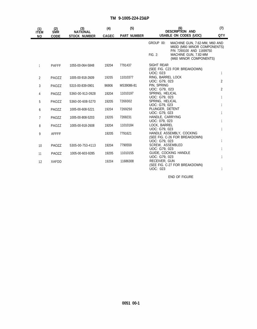
TM 9-1005-224-23&P
(1) (2) (3) (4) (5) (6) (7)ITEM SMR NATIONAL DESCRIPTION ANDNO CODE STOCK NUMBER CAGEC PART NUMBER USABLE ON CODES (UOC) QTY
1
2
3
4
5
6
7
8
9
10
11
12
PAFFF
PAOZZ
PAOZZ
PAOZZ
PAOZZ
PAOZZ
PAOZZ
PAOZZ
AFFFF
PAOZZ
PAOZZ
XAFDD
1055-00-064-5848
1005-00-918-2609
5315-00-839-0901
5360-00-913-0928
5360-00-608-5270
1005-00-608-5221
1005-00-808-5203
1005-00-918-2608
5305-00-753-4113
1005-00-603-9285
19204
19205
96906
19204
19205
19204
19205
19204
19205
19204
19205
19204
7791437 SIGHT REAR
11010377
MS39086-81
11010197
7269302
7269250
7269231
11010184
7791621
(SEE FIG. C23 FOR BREAKDOWN)UOC: 023 1RING, BARREL LOCKUOC: G79, 023 2PIN, SPRINGUOC: G79, 023 2SPRING, HELICALUOC: G79, 023 1SPRING, HELICAL
7790559
11010155
11686308
UOC: G79, 023 1PLUNGER, DETENTUOC: G79, 023 1HANDLE, CARRYINGUOC: 079, 023 1LOCK, BARRELUOC: G79, 023 1HANDLE ASSEMBLY, COCKING(SEE FIG. C-26 FOR BREAKDOWN)UOC: G79, 023 1SCREW, ASSEMBLEDUOC: G79, 023 1GUIDE, COCKING HANDLEUOC: G79, 023 1RECEIVER, GUN(SEE FIG. C-27 FOR BREAKDOWN)UOC: 023 1
END OF FIGURE
GROUP 00: MACHINE GUN, 7.62-MM, M60 ANDM60D (M60 MINOR COMPONENTS)P/N 7269100 AND 11699750
FIG. 2: MACHINE GUN, 7.82-MM(M60 MINOR COMPONENTS)
0051 00-1

TM 9-1005-224-23&P
GROUP 00: MACHINE GUN, 7.62MM, M60 AND M60D,(M60D MAJOR ASSEMBLIES)7269100 AND 11699750, REPAIR PARTS LIST 0052 00
*SEE FIGURE 4 FOR FURTHER DISASSEMBLY
NOTE: PHANTOMED PARTS ARE COMMON TO M60 MODEL. SEE FIGURE 1.
Figure 3. Group 00 Machine Gun, 7.62-MM M60 and M60D(M60D Major Assemblies), PN 7269100 and PN 11699750
0052 00-0

TM 9-1005-224-23&P
(1) (2) (3) (4) (5) (6) (7)ITEM SMR NATIONAL DESCRIPTION ANDNO CODE STOCK NUMBER CAGEC PART NUMBER USABLE ON CODES (UOC) QTY
1
2
3
4
5
6
7
8
9
10
11 PAOZZ 1005-00-909-3003
12 PAOZZ 1005-00-909-3016
13 PAOZZ 5315-00-067-3871
14 PAOOO 1005-00-909-3024
15
PA0ZZ
PAOOO
5340-00-913-5486
1005-00-987-9682
PAOZZ 4010-00-912-3627
PAOZZ 1005-00-912-3629
PAOZZ 5315-00-761-6881
PAOZZ 1005-00-909-3011
PAOZZ 5360-00-909-3021
PAOOO 1005-01-441-5508
PAOZZ 1005-00-909-3023
MOOZZ
PAOZZ 5315-00-909-3006
96906 MS17990C519
19205 7792096
19205 8427869-7
19204 8427871
96906 MS16562-151
19205 11699793
19204
19205
11699785
11699773
19200 11699790
19204 MS20995C32
19205
19204
96906
11699789
11699787
MS24665-18
19200
19205
11699751
11699788
GROUP 00: MACHINE GUN, 7.62-MM, M60 ANDM60D (M60D MAJOR ASSEMBLIES)P/N 7269100 AND 11699750
FIG. 3: MACHINE GUN, 7.62-MM(M60D MAJOR ASSEMBLIES)
PIN, QUICK RELEASEUOC: G79 1TRAY ASSEMBLY, CARTRIDGE FEED(SEE FIG. 21 FOR BREAKDOWN)UOC: G79 1WIRE ROPE ASSEMBLYUOC: G79 1SLEEVE, SWAGINGUOC: G79 2PIN, SPRINGUOC: G79 1ADAPTER, GUNUOC: G79 1SPRING, FLATUOC: G79 1SEAR AND SAFETY HOUSING(SEE FIG. 10 FOR BREAKDOWN)UOC: G79 1LINK AND SPRING, SEAR ASSEMBLYUOC: G79 1WIRE, SAFETY 0.032 IN.(MAKE FROM NSN 9505-00-293-4208)UOC: G79, 023 1NUT, SEAR LINKUOC: G79 1BOOT, DUST AND MOISTUREUOC: G79 1PIN, COTTERUOC: G79, 023 2GRIP AND TRIGGER ASSEMBLY(SEE FIG. 6 FOR BREAKDOWN) 1UOC: G79PIN, GROOVED, HEADEDUOC: G79 1
END OF FIGURE
0052 00-1

TM 9-1005-224-23&P
GROUP 00: MACHINE GUN, 7.62MM, M60 AND M60D,(M60D MINOR COMPONENTS),7269100 AND 11699750, REPAIR PARTS LIST 0053 00
NOTE: PHANTOMED PARTS ARE COMMON TO M60 MODEL. SEE FIGURE 2.
Figure 4. Group 00 Machine Gun, 7.62-MM, M60 and M60D(M60D Minor Components), PN 7239100 and PN 11699750
0053 00-0

TM 9-1005-224-23&P
(1) (2) (3) (4) (5) (6) (7)ITEM SMR NATlONAL DESCRIPTION AND
NO CODE STOCK NUMBER CAGEC PART NUMBER USABLE ON CODES (UOC) QTY
1
2
3
4
5
6
7
8
9
PAFZZ 1005-00-690-3505
PAFZZ 5315-00-066-6082
PAFZZ 1005-00-690-3504
PAOOO 1005-01-442-0162
19204
19204
19204
19205
7790554
7792069
7790553
11699796
XAFDD 19205 11699805
PAFZZ 1005-00-934-8312
PAFZZ 5320-00-075-7225
PAFZZ 5360-00-690-3502
PAFZZ 5310-00-067-3871
19204
19204
19204
96906
11686976
7792086
7790551
MS24665-18
GROUP 00: MACHINE GUN, 7.62-MM, M60 ANDM60D (M60D MINOR COMPONENTS)P/N 7269100 AND 11699750
FIG. 4: MACHINE GUN, 7.62-MM(M60D MINOR COMPONENTS)
LEVER, LOCK-RELEASEUOC: G79 1PIN, STRAIGHT, HEADEDUOC: G79 2PAWLUOC: G79 1SIGHT, REAR(SEE FIG. 25 FOR BREAKDOWN)UOC: G79 1RECEIVER ASSEMBLY, GUN(SEE FIG. 28 FOR BREAKDOWN)UOC: G79 1BRACKET, MAGAZINEUOC: G79 1RIVET, SOLIDUOC: G79 4SPRING, HELICALUOC: G79 2PIN, COTTERUOC: G79 2
END OF FIGURE
0053 00-1

TM 9-1005-224-23&P
GROUP 01: SHOULDER GUN STOCK ASSEMBLY (M60 ONLY),11686711, REPAIR PARTS LIST 0054 00
* NO FURTHER DISASSEMBLY AUTHORIZED.
Figure 5. Group 01 Shoulder Gun Stock Assembly (M60 only), PN 11686711
(1) (2) (3) (4)ITEM
(5)SMR NATlONAL
(6) (7)
NO CODEDESCRlPTlON AND
STOCK NUMBER CAGEC PART NUMBER USABLE ON CODES (UOC) QTY
1 PAOZZ 1005-00-919-7278 19204
2 PAOZZ 5305-00-920-7254 19205
3 PAOZZ 5365-00-919-7274 19204
4 PAFZZ 5320-00-852-6313 19205
GROUP 01: SHOULDER GUN STOCK ASSEMBLY(M60 ONLY), P/N 11686711
FIG. 5: M60 SHOULDER GUN STOCKASSEMBLY
7267089 SWIVEL, SLING, SMALLUOC: 023 1
11010365 SCREW, ASSEMBLEDUOC: 023 2
11010369 SPACER, PLATEUOC: 023 1
11686722 RIVET, SOLIDUOC: 023 2
END OF FIGURE
0054 00-0
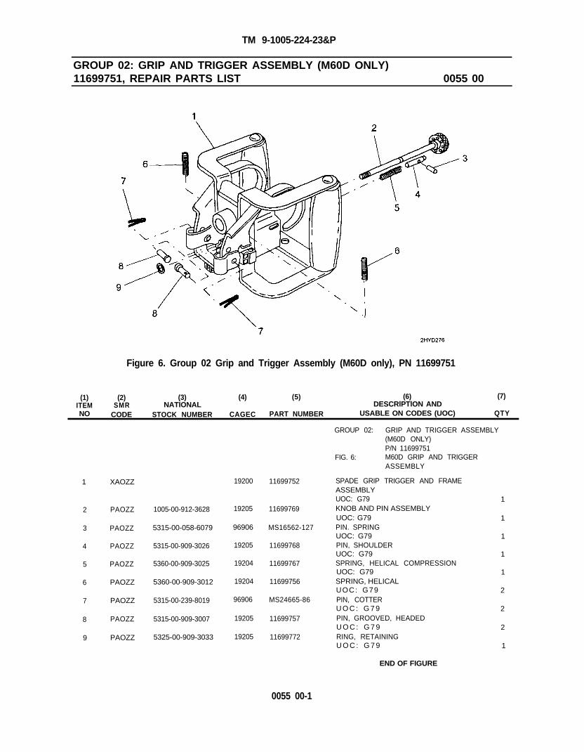
TM 9-1005-224-23&P
GROUP 02: GRIP AND TRIGGER ASSEMBLY (M60D ONLY)11699751, REPAIR PARTS LIST 0055 00
Figure 6. Group 02 Grip and Trigger Assembly (M60D only), PN 11699751
(1) (2) (3) (4) (5) (6) (7)ITEM SMR NATIONAL DESCRlPTlON ANDNO CODE STOCK NUMBER CAGEC PART NUMBER USABLE ON CODES (UOC) QTY
1 XAOZZ
2 PAOZZ
3
4
5
6
PAOZZ
PAOZZ
PAOZZ
PAOZZ
7 PAOZZ
8 PAOZZ
9 PAOZZ
1005-00-912-3628
5315-00-058-6079
5315-00-909-3026
5360-00-909-3025
5360-00-909-3012
5315-00-239-8019
5315-00-909-3007
5325-00-909-3033
19200 11699752
19205 11699769
96906 MS16562-127
19205 11699768
19204 11699767
19204 11699756
96906 MS24665-86
19205 11699757
19205 11699772
GROUP 02: GRIP AND TRIGGER ASSEMBLY(M60D ONLY)P/N 11699751
FIG. 6: M60D GRIP AND TRIGGERASSEMBLY
SPADE GRIP TRIGGER AND FRAMEASSEMBLYUOC: G79 1KNOB AND PIN ASSEMBLYUOC: G79 1PIN. SPRINGUOC: G79 1PIN, SHOULDERUOC: G79 1SPRING, HELICAL COMPRESSIONUOC: G79 1SPRING, HELICALUOC: G79 2PIN, COTTERU O C : G 7 9 2PIN, GROOVED, HEADEDU O C : G 7 9 2RING, RETAININGU O C : G 7 9 1
END OF FIGURE
0055 00-1

TM 9-1005-224-23&P
GROUP 03: BREECH BOLT ASSEMBLY.11010357, REPAIR PARTS LIST 0056 00
Figure 7. Group 03 Breech Bolt Assembly, PN 11010357
0056 00-0

TM 9-1005-224-23&P
(1) (2) (3) (4) (5) (6) (7)ITEM SMR NATIONAL DESCRIPTION ANDNO CODE STOCK NUMBER CAGEC PART NUMBER USABLE ON CODES (UOC) QTY
1 PAOZZ 1005-01-185-0735 19200 9362505
2
3
4
5
6
7
8
9
10
11
12
13
PAOZZ
PAOZZ
PAOZZ
PAFZZ
PAOZZ
PAOZZ
PAOZZ
PAOZZ
PAOZZ
PAOZZ
PAFZZ
PAOZZ
1005-00-608-5037
5360-00-608-5061
1005-00-608-5039
1005-00-872-4443
5315-00-839-0901
5360-01-015-6191
1005-00-872-4442
1005-00-608-5057
5360-00-606-5060
1005-00-779-6030
1005-00-872-4441
5315-00-994-9648
19204 7269063
19204 7269087
19204 7269065
19204 11010376
96906 MS39086-81
19204 12003125
19204 11010375
19204 7269083
19204 7269086
19204 7790907
19204 11010358
19204 7792920
GROUP 03: BREECH BOLT ASSEMBLYPIN 11010357
FIG. 7: BREECH BOLT ASSEMBLY
PLUG ASSEMBLY, BOLTREPLACES P/N 7791523UOC: G79, 023ACTUATOR ASSEMBLY, CAMUOC: G79, 023SPRING, HELICALUOC: G79, 023GUIDE, FlRlNG PINUOC: G79, 023PIN, FIRINGUOC: G79, 023PIN, SPRINGUOC: G79,SPRING, HELICALUOC: G79, 023EJECTOR, CARTRIDGEUOC: 079, 023PLUNGER, EXTRACTORUOC: G79, 023SPRING, HELICALUOC: G79, 023EXTRACTOR, CARTRIDGEUOC: G79, 023BOLT, BREECHUOC: G79, 023PIN, STRAIGHT, HEADLESSUOC: G79, 023
1
1
1
1
1
1
1
1
1
1
1
1
1
END OF FIGURE
0056 00-1

TM 9-1005-224-23&P
GROUP 04: OPERATING ROD ASSEMBLY,9362510, REPAIR PARTS LIST 0057 00
Figure 8. Group 04 Operating Rod Assembly, PN 9362510
(1) (2) (3) (4)ITEM
(5)SMR NATlONAL
(6) (7)
NO CODEDESCRlPTlON AND
STOCK NUMBER CAGEC PART NUMBER USABLE ON CODES (UOC) QTY
1 PAFZZ
2 XAFZZ
3 PAFZZ
4 PAFZZ
1005-01-185-0734 19200
19200
5315-00-940-9490 96906
5315-01-183-2860 19200
9362506
9362509
MS51923-105
9362507
GROUP 04: OPERATING ROD ASSEMBLYPIN 9362510
FIG. 8: OPERATING ROD ASSEMBLY
ROLLER, YOKEREPLACES P/N 7790942UOC; G79, 023 1YOKE AND TUBE ASSEMBLYREPLACES PIN 7790944UOC: G79, 023 1PIN, SPRINGUOC: G79, 023 1PIN, STRAIGHT, HEADLESSREPLACES 11010215UOC: G79, 023 1
END OF FIGURE
0057 00-0

(This page intentionally left blank)

TM 9-1005-224-23&P
GROUP 05: TRIGGER MECHANISM GRIP ASSEMBLY (M60 ONLY)7269202, REPAIR PARTS LIST 0058 00
Figure 9. Group 05 Trigger Mechanism Grip Assembly (M60 only), PN 7269202
0058 00-0

TM 9-1005-224-23&P
(1) (2) (3) (4) (5) (6) (7)ITEM SMR NATIONAL DESCRIPTION AND
NO CODE STOCK NUMBER CAGEC PART NUMBER USABLE ON CODES (UOC) QTY
1 PAOZZ
2 PAOZZ
3 PAOZZ
4 PAOZZ
5 PAOZZ
6 PAOZZ
7 PAOZZ
8 PAOZZ
9 PAOZZ
10 XAOZZ
1005-00-069-9358
5315-00-608-5178
5360-00-608-5183
1005-00-608-5179
1005-00-608-5182
1005-00-608-5180
5360-00-608-5184
1005-00-608-5185
5315-00-608-5177
19204 7269415
19204 7269205
19204 7269210
19204 7269206
19204 7269209
19204 7269207
19204 7269211
19204 7269212
19205 7269204
19204 7269203
GROUP 05: TRIGGER MECHANISM GRIPASSEMBLY (M60 ONLY),P/N 7269202
FIG. 9: TRIGGER MECHANISM GRIPASSEMBLY
SAFETY, SMALL ARMSUOC: 023PIN, GROOVED, HEADEDUOC: 023SPRING, HELICALUOC: 023PLUNGER, SAFETYUOC: 023SEARUOC: 023PLUNGER, SEARUOC: 023SPRING, HELICALUOC: 023TRIGGER ASSEMBLYUOC: 023PIN, SHOULDER, HEADEDUOC: 023HOUSING, TRIGGERUOC: 023
END OF FIGURE
1
1
1
1
1
1
1
1
1
1
0058 00-1

TM 9-1005-224-23&P
GROUP 06: SEAR AND SAFETY HOUSING ASSEMBLY (M60D ONLY)11699773, REPAIR PARTS LIST 0059 00
Figure 10. Group 06 Sear and Safety Housing Assembly (M60D only), PN 11699773
0059 00-0

TM 9-1005-224-23&P
(1) (2) (3)ITEM SMR NATlONALNO CODE STOCK NUMBER
(4) (5) (6) (7)DESCRIPTION AND
CAGEC PART NUMBER USABLE ON CODES (UOC) QTY
GROUP 06: SEAR AND SAFETY HOUSINGASSEMBLY (M60D ONLY),P/N 11699773
FIG. 10: M60D SEAR AND SAFETY HOUSINGASSEMBLY
1 PAOZZ
2 PAOZZ
3 PAOZZ
4 PAOZZ
5 PAOZZ
6 PAOZZ
7 PAOZZ
8 PAOZZ
9 PAOZZ
10 XAOZZ
5360-00-909-3017
1005-00-909-3009
5315-00-909-3004
3120-00-909-3005
1005-00-608-5182
1005-00-608-5180
5360-00-608-5184
1005-00-909-3008
1005-00-909-3014
19204
19205
19204
19204
19204
19204
19204
19204
19205
19205
11699775
11699776
11699779
11699778
7269209
7269207
7269211
11699777
11699780
11699774
SPRING, HELICALUOC: G79PLUNGER, SAFETYUOC: G79PIN, GROOVED, HEADEDUOC: G79BUSHING, SLEEVEUOC: G79SEARUOC: G79PLUNGER, SEARUOC: G79SPRING, HELICALUOC: G79SAFETY, SMALL ARMSUOC: G79ACTIVATOR, SEARUOC: G79HOUSING, SEARUOC: G79
END OF FIGURE
1
1
1
1
1
1
1
1
1
1
0059 00-1

TM 9-1005-224-23&P
GROUP 07: BARREL AND BIPOD ASSEMBLY,7269027, REPAIR PARTS LIST 0 0 6 0 0 0
Figure 11. Group 07 Barrel and Bipod Assembly, PN 7269027
0060 00-0

TM 9-1005-224-23&P
(1) (2) (3) (4) (5) (6) (7)ITEM SMR NATIONAL DESCRIPTION ANDNO CODE STOCK NUMBER CAGEC PART NUMBER USABLE ON CODES (UOC) O N
1 XAFZZ
2 PAOZZ
3 PAOZZ
4 PAOZZ
5 PAOZZ
5365-00-608-5005
5310-00-608-5009
1005-00-875-4350
1005-01-209-3590
6 PAOZZ 9505-00-293-4208
7 PAOZZ
8 PAFZZ
9 PAFZZ
10 PAFFF
1005-00-608-5004
1005-00-608-5008
5315-01-285-0610
1005-00-020-8683 7793009
12599983
7269034
7269030
MS20995C32
19204 7269028
19204 7269031
19204 7269035
19204 7791247
19200 9362515
96906
19204
19204
19200
19204
GROUP 07: BARREL AND BIPOD ASSEMBLYP/N 7269027
FIG. 11: BARREL AND BIPOD ASSEMBLY
BARREL AND GUN ASSEMBLYUOC: G79, 023 1BUSHING, MACHINEUOC: G79, 023 1WASHER, KEYUOC: G79, 023 2PISTON, GASUOC: G79, 023 1PLUG ASSEMBLY, GASREPLACES P/N 7792093UOC: G79, 023 1WIRE, SAFETY 0.032 IN.(MAKE FROM NSN 9505-00-293-4208)UOC: G79, 023 1PLUG, VENTUOC: G79, 023 1SUPRESSOR, FLASHUOC: G79, 023 1PIN, STRAIGHTUOC: G79, 023 1BIPOD, MACHINE GUN(SEE FIG. 12 FOR BREAKDOWN)UOC: G79, 023 1
END OF FIGURE
0060 00-1

TM 9-1005-224-23&P
GROUP 0701: MACHINE GUN BIPOD,7793009, REPAIR PARTS LIST 0061 00
Figure 12. Group 0701 Machine Gun Bipod, PN 7703099
0061 00-0

TM 9-1005-224-23&P
(1) (2) (3) (4) (5) (6) (7)ITEM SMR NATlONAL DESCRIPTION AND
NO CODE STOCK NUMBER CAGEC PART NUMBER USABLE ON CODES (UOC) QTY
1
2
3
4
5
6
7
8 PAFZZ 1005-00-608-5021 19204 7269047
PAFZZ
PAFZZ
PAFZZ
PAFZZ
PAFZZ
XAFZZ
PAFZZ
5305-00-608-5025
5315-00-608-5022
5315-00-608-5024
5360-00-608-5026
1005-00-608-5027
1005-00-608-5020
19204 7269051
19204 7269048
19204 7269050
19204 7289052
19204 7269053
19204 7793010
19204 7269046
GROUP 0701: MACHINE GUN BIPODPIN 7793009
FIG. 12: MACHINE GUN BIPOD
SCREW, SHOULDERUOC: G79, 023PIN, GROOVEDUOC: G79, 023PIN, STRAIGHT, HEADEDUOC: G79, 023SPRING, HELICALUOC: G79, 023RETAINER, SPRING LEGUOC: G79, 02PIVOT, BIPOD ASSEMBLYUOC: G79, 023LEG, MACHINE GUN (LEFT)(SEE FIG. 14 FOR BREAKDOWN)UOC: G79, 023LEG, MACHINE GUN (RIGHT)(SEE FIG. 13 FOR BREAKDOWN)UOC: G79, 023
2
2
2
2
2
1
1
1
END OF FIGURE
0061 00-1

TM 9-1005-224-23&P
GROUP 070101: MACHINE GUN LEG (RIGHT),7269047, REPAIR PARTS LIST 0062 00
Figure 13. Group 070101 Machine Gun Leg (Right), PN 7269047
(1) (2) (3) (4) (5) (6) (7)ITEM SMR NATIONAL DESCRIPTION ANDNO CODE STOCK NUMBER CAGEC PART NUMBER USABLE ON CODES (UOC) QTY
GROUP 070101: MACHINE GUN LEG (RIGHT)PIN 7269047
FIG. 13: MACHINE GUN LEG (RIGHT)
1 PAFZZ 5320-00-606-5032 19204 7269058 RIVET, SOLIDUOC: G79, 023 2
2 PAFZZ 5315-00-196-2753 19204 7269057 KEY, MACHINEUOC: G79, 023 1
END OF FIGURE
0062 00-0

TM 9-1005-224-23&P
GROUP 070102: MACHINE GUN LEG (LEFT),7269046, REPAIR PARTS LIST 0063 00
Figure 14. Group 070102 Machine Gun Leg (Left), PN 7269046
(1) (2) (3) (4) (5) (6) (7)ITEM SMR NATIONAL DESCRIPTION ANDNO CODE STOCK NUMBER CAGEC PART NUMBER USABLE ON CODES (UOC) QTY
GROUP 070102: MACHINE GUN LEG (LEFT)PIN 7269046
FIG. 14: MACHINE GUN LEG (LEFT)
1 PAFZZ 5320-00-608-5032 19204 7269058 RIVET, SOLIDUOC: G79, 023 2
2 PAFZZ 5315-00-196-2753 19204 7269057 KEY, MACHINEUOC: G79, 023 1
END OF FIGURE
0063 00-1

TM 9-1005-224-23&P
GROUP 08: COVER ASSEMBLY,7269114, REPAIR PARTS LIST 0064 00
Figure 15. Group 08 Cover and Lever Assembly, PN 7269114
0064 00-0

TM 9-1005-224-23&P
(1) (2) (3) (4) (5) (6) (7)ITEM SMR NATIONAL DESCRIPTION AND
NO CODE STOCK NUMBER CAGEC PART NUMBER USABLE ON CODES (UOC) QTY
1 PAFFF 1005-00-999-6003 19204 11699814
2 PAFZZ
3 PAFZZ
4 AFFFF
1005-00-608-5090 19204
1005-00-608-5089 19204
7269117
7269116
19204 7269119
5 PAFZZ
6 PAFFF
5360-00-912-1146 19204 11686315
1005-00-608-5093 19204 7269120
7 PAFZZ
8 PAOZZ
9 PAFFF
1005-00-013-7030
5315-00-067-3871
19204 11010152
19206 MS24665-18
1005-00-608-5091 19204 7269118
GROUP 08: COVER ASSEMBLYP/N 7269114
FIG. 15: COVER AND LEVER ASSEMBLY
CAM ASSEMBLY, FEED(SEE FIG. 16 FOR BREAKDOWN)UOC: G79, 023 1GUIDE, CARTRIDGE REARUOC: G79, 023 1GUIDE, CARTRIDGE FRONTUOC: G79, 023 1LEVER ASSEMBLY, FEED(SEE FIG. 16 FOR BREAKDOWN)UOC: G79, 023 1SPRING, HELICALUOC: G79, 023 1PAWL ASSEMBLY, CAM FEED(SEE FIG. 17 FOR BREAKDOWN)UOC: G79, 023 1SHAFT, STRAIGHTUOC: G79, 023 1PIN, COTTERUOC: G79, 023 1HOUSING ASSEMBLY, COVER(SEE FIG. 18 FOR BREAKDOWN)UOC: G79, 023 1
END OF FIGURE
0064 00-1

TM 9-1005-224-23&P
GROUP 0801: FEED CAM ASSEMBLY, 11699814 ANDGROUP 0802: FEED LEVER ASSEMBLY, 7269119, REPAIR PARTS LIST 0065 00
Figure 16. Group 0801 and 0802 Feed Cam Assembly, PN 11699814,and Feed Lever Assembly, PN 7269119
(1) (2) (3) (4)ITEM
(5)SMR NATlONAL
(6) (7)
NODESCRlPTlON AND
CODE STOCK NUMBER CAGEC PART NUMBER USABLE ON CODES (UOC) QTY
1 PAFZZ 1005-00-608-5096 19204
2 PAFZZ 5360-00-608-5098 19204
3 XAFZZ 19204
4 PAFZZ 1005-00-608-5097 19204
5 PAFZZ 1005-00-608-5119 19204
6 PAFZZ 1005-00-608-5118 19204
GROUP 0801: FEED CAM ASSEMBLY,PIN 7269114 AND
GROUP 0802: FEED LEVER ASSEMBLY,PIN 7269119
FIG. 16: FEED CAM ASSEMBLY ANDFEED LEVER ASSEMBLY
7269123
7269125
11699617
7269124
7269146
7269145
PLUNGER, RETAINERUOC: G79, 023SPRING, HELICALUOC: G79, 023CAM ASSEMBLYUOC: G79, 023RETAINER, FEED CAMUOC: G79, 023
CLIP, SPRING LEVERUOC: 079, 023
LEVER, FEEDUOC: G79, 023
1
1
1
1
1
1
END OF FIGURE
0065 00-0

TM 9-1005-224-23&P
GROUP 0803: FEED PAWL ASSEMBLY,7269120, REPAIR PARTS LIST 0066 00
Figure 17. Group 0803 Feed Pawl Assembly, PN 7269120
(1) (2) (3) (4) (5) (6) (7)ITEM SMR NATlONAL DESCRlPTlON ANDNO CODE STOCK NUMBER CAGEC PART NUMBER USABLE ON CODES (UOC) QTY
GROUP 0803: FEED PAWL ASSEMBLYP/N 7269120
FIG. 17: FEED PAWL ASSEMBLY
1 XAFZZ
2 PAFZZ
3 XAFZZ
4 PAFZZ
5360-00-608-5125
1005-00-608-5124
19205 7269149 CHASSIS ASSEMBLYUOC: G79, 023 1
19204 7269152 SPRING, HELICALUOC: G79, 023 1
19204 7269150 PAWLUOC; G79. 023 1
19204 7269151 SHAFT, SHOULDEREDUOC: G79, 023 1
END OF FIGURE
0066 00-1

TM 9-1005-224-23&P
GROUP 0804: COVER HOUSING ASSEMBLY,7269118, REPAIR PARTS LIST 0067 00
Figure 18. Group 0804 Cover Housing Assembly, PN 7269118
0067 00-0

TM 9-1005-224-23&P
(1) (2) (3) (4) (5) (6) (7)ITEM SMR NATIONAL DESCRIPTION AND
NO CODE STOCK NUMBER CAGEC PART NUMBER USABLE ON CODES (UOC) QTY
1
2
3
4
5
6
7
8
9
10
11
12
13
PAFZZ
PAFZZ
PAFZZ
PAFZZ
PAFZZ
1005-00-608-5109
5360-00-870-2118
1005-00-608-5110
5315-00-878-8615
1005-01-183-0709
PAFZZ 5360-00-608-5114
PAFZZ
PAFZZ
5310-00-981-8623
5315-00-608-5116
XAFZZ
PAFZZ 1005-00-608-5113
PAFZZ 5320-00-608-5112
PAFZZ 5320-00-608-5085
PAFZZ 1005-00-608-5111
19204
19204
19204
19205
19200
19204
19204
19205
19204
19204
19204
19204
19204
7269136
7791271
7269137
7791270
9362520
7269141
7269144
7269143
7269128
7269140
7269139
7269112
7269138
GROUP 0804: COVER HOUSING ASSEMBLY
1
1
1
1
1
2
2
2
1
1
2
9
1
P/N 7269118FIG. 18: COVER HOUSING ASSEMBLY
LATCH, COVERUOC: G79, 023SPRING, HELICALUOC: G79, 023LEVER ASSEMBLY, LATCHUOC: G79, 023PIN, STRAIGHT, HEADLESSUOC: G79, 023MOUNT ASSEMBLY(REPLACES P/N 7289126)UOC: G79, 023SPRING, HELICALUOC: G79, 023WASHER, FLATUOC: G79, 023PIN, SHOULDER, HEADEDUOC: G79, 023FRAME ASSEMBLY, COVERUOC: G79, 023SHIELD, COVERUOC: G79, 023RIVET, SOLIDUOC: G79, 023RIVET, SOLIDUOC: G79, 023PAD ASSEMBLY, CHEEKUOC: G79, 023
END OF FIGURE
0067 00-1

TM 9-1005-224-23&P
GROUP 09: TRAY AND HANGER ASSEMBLY (M60 ONLY),8448237, REPAIR PARTS LIST 0068 00
Figure 19. Group 09 Tray and Hanger Assembly (M60 only), PN 8448237
(1) (2) (3) (4)ITEM SMR
(5)NATIONAL
(6) (7)
NO CODEDESCRlPTlON AND
STOCK NUMBER CAGEC PART NUMBER USABLE ON CODES (UOC) QTY
GROUP 09: TRAY AND HANGER ASSEMBLY(M60 ONLY)P/N 6446237
FIG. 19: TRAY AND HANGER ASSEMBLY
1 XAOZZ 19204 6448415 TRAY ASSEMBLY, CARTRIDGE FEED(SEE FIG. 20 FOR BREAKDOWN)UOC: 023
2 PAOZZ 1005-00-403-95071
19204 8448414 HANGER ASSEMBLYUOC: 023 1
END OF FIGURE
0068 00-0

TM 9-1005-224-23&P
GROUP 0901: CARTRIDGE FEED TRAY ASSEMBLY (M60 ONLY)8448415, REPAIR PARTS LIST 0069 00
Figure 20. Group 0901 Cartridge Feed Tray Assembly (M60 only), PN 8448415
(1) (2)ITEM SMRNO CODE
(3)NATlONAL
STOCK NUMBER
(4) (5) (6) (7)DESCRIPTION AND
CAGEC PART NUMBER USABLE ON CODES (UOC) QTY
GROUP 0901: CARTRIDGE FEED TRAYASSEMBLY (M60 ONLY)P/N 8448415
FIG. 20: M60 CARTRIDGE FEED TRAYASSEMBLY
1 XAOZZ 19204 7792097
2 PAOZZ 1005-00-768-7084 19204 7790724
3 PAOZZ 1005-00-606-5299 19204 7269332
4 PAOZZ 5360-00-608-5302 19204 7269335
FRAME ASSEMBLY, CARTRIDGE TRAYUOC: G79, 023 1SHAFT, CARTRIDGEUOC: G79, 023 1PAWL CARTRIDGE RETAINERUOC: G79, 023 1SPRING, HELICALUOC: G79, 023 1
END OF FIGURE
0069 00-1

TM 9-1005-224-23&P
GROUP 10: CARTRIDGE FEED TRAY ASSEMBLY (M60D ONLY),7792996, REPAIR PARTS LIST 0070 00
Figure 21. Group 10 Cartridge Feed Tray Assembly (M60D only), PN 7792096
(1) (2) (3) (4) (5)ITEM SMR NATlONAL
(6) (7)DESCRlPTlON AND
NO CODE STOCK NUMBER CAGEC PART NUMBER USABLE ON CODES (UOC) QTY
1 XAOZZ 19204 7792097
2 PAOZZ 1005-00-766-7064 19204 7790724
3 PAOZZ 3120-00-606-5300 19204 7269333
4 PAOZZ 1005-00-608-5299 19204 7269332
5 PAOZZ 5360-00-608-5302 19204 7269335
GROUP 10: CARTRIDGE FEED TRAY ASSEMBLY
FIG. 21:
(M60D ONLY)P/N 7792096M60D CARTRIDGE FEED TRAYASSEMBLY
FRAME ASSEMBLY, CARTRIDGE TRAYUOC: G79, 023 1SHAFT, CARTRIDGEUOC: G79, 023 1ROLLER, LINEAR-ROTARYUOC: G79 2PAWL CARTRIDGE CONTAINERUOC: G79, 023 1SPRING, HELICALUOC: G79, 023 1
END OF FIGURE
0070 00-0

TM 9-1005-224-23&P
GROUP 11: FOREARM ASSEMBLY (M60 ONLY),11010430, REPAIR PARTS LIST 0071 00
Figure 22. Group 11 Forearm Assembly, PN 11010430
(1) (2)ITEM SMRNO CODE
(3)NATlONAL
STOCK NUMBER
(4) (5) (6) (7)DESCRlPTlON AND
CAGEC PART NUMBER USABLE ON CODES (UOC) QTY
GROUP 11: FOREARM ASSEMBLY(M60 ONLY)P/N 11010430
FIG. 22: M60 FOREARM ASSEMBLY
1 PAOZZ
2 PAOZZ
3 PAOZZ
4 PAOZZ
5 PAOZZ
6 PAOZZ
7 XAOFF
8 XAOFF
5365-00-919-7274
5360-00-608-5160
5315-00-608-5157
5340-01-337-0259
5305-00-920-7254
1005-00-919-7278
19204 11010369
19204 7269187
19204 7269184
19200 12940984
19205 11010365
19204 7267089
19204 7269190
19204 7269183
SPACER, PLATEUOC: 023SPRING, FIATUOC: 023PIN, SHOULDERUOC: 023CATCH, FOREARMUOC: 023SCREW, ASSEMBLEDUOC: 023SWIVEL, SLING, SMALLUOC: 023SHELL ASSEMBLY FOREARMUOC: 023COVER ASSEMBLY FOREARMUOC: 023
1
1
1
1
2
1
1
1
END OF FIGURE
0071 00-1

TM 9-1005-224-23&P
GROUP 12: REAR SIGHT (M60 ONLY),7791437, REPAIR PARTS LIST 0072 00
Figure 23. Group 12 Rear Sight (M60 only), PN 7791437
0072 00-0

TM 9-1005-224-23&P
(1) (2)ITEM SMRNO CODE
(3) (4) (5) (6) (7)NATlONAL DESCRIPTION AND
STOCK NUMBER CAGEC PART NUMBER USABLE ON CODES (UOC) QTY
1 XAFFF 19204 7269279
2 PAFZZ 3110-00-950-4236 96906 MS19061-20005
3 PAFZZ 5360-00-608-5251 19204 7269283
4 PAFZZ 5320-00-608-5248 19204 7269280
5 XAFZZ 19204 7269282
6 PAFZZ 1005-01-158-4507 19204 7269278
7 PAFZZ 5315-00-608-5249 19204 7269281
GROUP 12: REAR SIGHT (M60 ONLY)PIN 7791437
FIG. 23: M60 REAR SIGHT
LEAF ASSEMBLY, REAR SIGHT(SEE FIG. 24 FOR BREAKDOWN)UOC: 023 1BALL, BEARINGUOC: 023 2SPRING, HELICALUOC: 023 2RIVET, TUBULARUOC: 023 1SLIDE. LATERALUOC: 023 1BASE ASSEMBLY, REARUOC: 023 1PIN, SHOULDERUOC: 023 1
END OF FIGURE
0072 00-1

TM 9-1005-224-23&P
GROUP 1201: REAR SIGHT LEAF ASSEMBLY (M60 ONLY)7269279, REPAIR PARTS LIST 0073 00
Figure 24. Group 1201 Rear Sight Leaf Assembly (M60 only), PN 7269279
0073 00-0

TM 9-1005-224-23&P
(1) (2) (3)ITEM SMR NATIONALNO CODE STOCK NUMBER
(4) (5) (6) (7)DESCRIPTION AND
CAGEC PART NUMBER USABLE ON CODES (UOC) QTY
GROUP 1201: REAR SIGHT LEAF ASSEMBLY(M60 ONLY)P/N 7269279
FIG. 24: M60 REAR SIGHT LEAF ASSEMBLY
1
2
3
4
5
6
7
8
9
10
11
12
13
14
XAFZZ
XAFZZ
XAFZZ
PAFZZ
XAFZZ
PAFZZ
PAFZZ
PAFZZ
XAFZZ
XAFZZ
PAFZZ
PAFZZ
PAFZZ
PAFZZ
5360-00-608-5267
5360-00-608-5266
5360-00-608-5255
3110-00-950-8446
5305-00-608-5264
1005-00-066-2786
5320-00-606-5262
5320-00-608-5261
19204 7269295
19204 7269288
19204 7269289
19205 7269299
19204 7269292
19205 7269298
19204 7269267
96906 MS19061-3
19204 7269291
19204 7269290
19204 7269296
19204 11686738
19205 7269294
19205 7269293
SCREW, ELEVATIONUOC: 023CAP, LEAF FRAMEUOC: 023SLIDEUOC: 023SPRING, HELICALU O C : 0 2 3RELEASE ASSEMBLYU O C : 0 2 3SPRING, HELICALU O C : 0 2 3SPRING, HELICALUOC: 023BALL, BEARINGUOC: 023KNOB, ELEVATINGUOC: 023LEAF, REAR SIGHTUOC: 023SCREW, MACHINEU O C : 0 2 3SCALE, ELEVATIONU O C : 0 2 3RIVET, SOLID CAP, RHUOC: 023RIVET, TUBULAR CAP, LHU O C : 0 2 3
END OF FIGURE
1
1
1
1
1
1
1
1
1
1
1
1
1
1
0073 00-1
TM 9-1005-224-23&P
GROUP 13: REAR SIGHT (M60D ONLY),11699796, REPAIR PARTS LIST 0074 00
Figure 25. Group 13 Rear Sight (M60D only), PN 11699796
(1) (2) (3) (4) (5)ITEM SMR NATIONAL
(6) (7)DESCRlPTlON AND
NO CODE STOCK NUMBER CAGEC PART NUMBER USABLE ON CODES (UOC) QTY
1 PAOZZ
2 PAOZZ
3 PAOZZ
4 PAOZZ
5 PAOZZ
6 XAOZZ
7 PAOZZ
5315-00-812-3312
1005-00-909-3018
3110-00-100-6149
5360-00-952-4705
1
1
1
1
1
1
1
1005-00-909-4179
5310-00-158-4447
96906 MS16562-119
19204 11699799
96906 MS19059-2412
96908 MS24585-75
19205 11699798
19205 11699797
19205 11699763
GROUP 13: REAR SIGHT(M60D ONLY)P/N 11699796
FIG. 25: M60D REAR SIGHT
PIN. SPRINGUOC: G79RING, SIGHTUOC: G79BALL, BEARINGUOC: G79SPRING, HELICALUOC: G79RETAINER, REAR SIGHTUOC: G79BASE, REAR SIGHTUOC: G79NUT, SELF-LOCKINGUOC: G79
END OF FIGURE
0074 00-0

TM 9-1005-224-23&P
GROUP 14: COCKING HANDLE ASSEMBLY,7791621, REPAIR PARTS LIST 0075 00
Figure 26. Group 14 Cocking Handle Assembly, 7791621
(1) (2) (3) (4) (5) (6) (7)ITEM SMR NATlONAL DESCRIPTION AND
NO CODE STOCK NUMBER CAGEC PART NUMBER USABLE ON CODES (UOC) QTY
GROUP 14: COCKING HANDLE ASSEMBLYPIN 7791621
FIG. 26: COCKING HANDLE ASSEMBLY
1 PAFZZ 1005-00-608-5208 19205 7269237 RETAINER, COCKING HANDLEUOC: G79, 023 1
2 PAFZZ 5360-00-066-6061 19204 7791522 SPRING, HELICALUOC: G79, 023 1
3 PAFZZ 1005-00-608-5210 19204 7269239 SLIDE ASSEMBLYUOC: G79, 023 1
END OF FIGURE
0075 00-1

TM 9-1005-224-23&P
GROUP 15: GUN RECEIVER ASSEMBLY (M60 ONLY),11686308, REPAIR, PARTS LIST 0076 00
Figure 27. Group 15 Gun Receiver Assembly (MS0 only), PN 11686308
(1) (2) (3) (4)ITEM
(5)SMR NATIONAL
(6) (7)
NODESCRIPTION AND
CODE STOCK NUMBER CAGEC PART NUMBER USABLE ON CODES (UOC) QTY
GROUP 15: GUN RECEIVER ASSEMBLY(M60 ONLY)PIN 11686308
FIG. 27: M60 GUN RECEIVER ASSEMBLY
1 PAFZZ 5320-00-071-8945 19205 7269411
2 PAFZZ 5320-083-0290 19204 7792972
3 PAFZZ 5315-00-083-0293 19204 7792976
4 PAFZZ 5315-00-083-0292 19204 7792975
5 PAFZZ 5315-00-083-0289 19204 7792971
6 PAFZZ 1005-00-083-0291 19204 7792974
7 XADDA 19200 11686307
RIVET, SOLIDUOC: 023RIVET, SOLIDUOC: 023PIN, STRAIGHT MOUNTING, FRONTUOC: 023PIN, STRAIGHTUOC: 023PIN, STRAIGHT, HEADEDUOC: 023PLATE, MOUNTINGUOC: 023RECEIVER ASSEMBLYUOC: 023
4
2
1
1
2
1
1
END OF FIGURE
0076 00-0

TM 9-1005-224-23&P
GROUP 16: GUN RECEIVER ASSEMBLY (M60D ONLY),11699805, REPAIR PARTS LIST 0077 00
Figure 28. Group 16 Gun Receiver Assembly (M60D only), PN 11699805
(1) (2) (3) (4) (5)ITEM SMR
(6)NATIONAL
(7)DESCRIPTION AND
NO CODE STOCK NUMBER CAGEC PART NUMBER USABLE ON CODES (UOC) QTY
GROUP 16: GUN RECEIVER ASSEMBLY
1 PAFZZ 5320-00-071-8945 19205
2 PAFZZ 5320-00-083-0290 19204
3 PAFZZ 1005-00-083-0291 19204
4 XADDA 19200
7269411
7792972
7792974
11686307
(M60D ONLY)PIN 11699805
FIG. C-28: M60D GUN RECEIVER ASSEMBLY
RIVET, SOLIDUOC: G79 4RIVET, SOLIDUOC: G79 2PLATE, MOUNTINGUOC: G79, 023 1RECEIVER ASSEMBLYUOC: G79 1
END OF FIGURE
0077 00-1

TM 9-1005-224-23&P
(This page intentionally left blank)

TM 9-1005-224-23&P
GROUP 9999BULK MATERIAL 0078 00
(1) (2) (3) (4) (5) (6) (7)ITEM SMR NATIONAL DESCRIPTION AND
NO CODE STOCK NUMBER CAGEC PART NUMBER USABLE ON CODES (UOC) QTY
GROUP 9999: BULK MATERIAL
FIG. BULK
1 PAOZZ 9505-00-293-4208 96906 MS20995C32 WIRE, NON-ELECTRICAL
END OF FIGURE
0078 00-1

TM 9-1005-224-23&P
GROUP 9500: SPECIAL TOOLSREPAIR PARTS LIST 0079 00
Figure 29. Group 9500 Special Tools
0079 00-0

TM 9-1005-224-23&P
(1) (2) (3) (4) (5) (6) (7)ITEM SMR NATIONAL DESCRIPTION ANDNO CODE STOCK NUMBER CAGEC PART NUMBER USABLE ON CODES (UOC) QTY
2 PAFZZ 4933-00-653-3373 19205 7274754
3 PAFZZ 4933-00-069-8676 19205 7274786
4 PAFZZ 4933-00-647-3698 19205 7274790
5
6
7 ADFDD 19204 5910297
8 PAFZZ 5140-00-313-9486 19205 7319995
9
10
11
PAFZZ 4933-00-317-2504 19205 7319994
PAFZZ 4933-00-317-2501 19205 7274724
PAFZZ 5210-00-234-5223 81348 GGG-R-791
12 PAFZZ 6670-00-254-4634 81348 AAA-S-133
1 PAFZZ 5140-00-473-6260 81348 GGGT558-2
PAFZZ 4933-00-653-9550 19205 7799699
PAFZZ 5220-00-745-8598 19205 7458598
GROUP 9500: SPECIAL TOOLS
FIG. 29: SPECIAL TOOLS
TOOL BOX, PORTABLE(BOI: 2 PER SUPPORTING DS/GSMAINTENANCE COMPANY)UOC: G79,023
GAGE, FIRING PIN PROTRUSION 0.035TO 0.043(BOl: 2 PER SUPPORTING DS/GSMAINTENANCE COMPANY)UOC: G79,023
GAGE, HEADSPACE 1.6415 IN M60PREEMBARKATION(BOI: 2 PER SUPPORTING DS/GSMAINTENANCE COMPANY)UOC: G79,023
GAGE, HEADSPACE 1.6455 IN M60SERIES FIELD REJECTION(BOI: 2 PER SUPPORTING DS/GSMAINTENANCE COMPANY)UOC: G79,023
GAGE, TEST BOLT(BOI: 2 PER SUPPORTING DS/GSMAINTENANCE COMPANY)UOC: G79,023
GAGE, PLUG, PLAIN CYLINDRICAL SGLEEND NO GO 0.018 OD M60 SERIES(BOI: 2 PER SUPPORTING DS/GSMAINTENANCE COMPANY)UOC: G79,023
GAGE KIT, SMALL ARMS(BOI: 2 PER M8 SERIES SUPPORTINGDS/GS MAINTENANCE COMPANY)UOC: G79,023
CASE, CARRYING, GAGE (1) 36-7GAGE, BARREL EROSION (1) 36-8GAGE, WEAR CHECK (1) 36-9
CASE, CARRYING, GAGEPART OF KIT P/N 5910297UOC: G79,023
GAGE BARREL EROSION, CAL .30, M8SERIESPART OF KIT P/N 5910297
GAGE WEAR CHECKPART OF KIT P/N 5910297
RULE, STEEL(BOI: 2 PER SUPPORTING DS/GSMAINTENANCE COMPANY)UOC: G79,023
SCALE, DIAL(BOI: 2 PER SUPPORTING DS/GSMAINTENANCE COMPANY)UOC: 110
0079 00-1

TM 9-1005-224-23&P
(1) (2) (3) (4)ITEM
(5)SMR NATIONAL
(6) (7)
NO CODEDESCRIPTION AND
STOCK NUMBER CAGEC PART NUMBER USABLE ON CODES (UOC) QTY
13 PAFZZ 5210-00-078-8949 81348
14 PAFZZ 4933-00-077-2081 19204
GGG-S-656
8436748
GROUP 9500: SPECIAL TOOLS (CONT)
FIG. 29: SPECIAL TOOLS
SQUARE, COMBINATION(BOI: 2 PER SUPPORTING DS/GSMAINTENANCE COMPANY)
STOP TOOL, SCREW(BOI: 2 PER SUPPORTING DS/GSMAINTENANCE COMPANY)UOC: 110
END OF FIGURE
0079 00-2

TM 9-1005-224-23&P
PART NUMBER INDEX 0080 00
PART NUMBER FIG. ITEM PART NUMBER FIG. ITEM
A A A - S - 1 3 3G G G - R - 7 9 1G G G - S - 6 5 6G G G T 5 5 8 - 2M S 1 6 5 6 2 - 1 1 9M S 1 6 5 6 2 - 1 2 7M S 1 6 5 6 2 - 1 5 1M S 1 7 9 9 0 C 5 1 9M S 1 9 0 5 9 - 2 4 1 2M S 1 9 0 6 1 - 2 0 0 0 5M S 1 9 0 6 1 - 3M S 2 0 9 9 5 C 3 2
M S 2 4 5 8 5 - 7 5M S 2 4 6 6 5 - 1 8
M S 2 4 6 6 5 - 8 6M S 3 9 0 8 6 - 8 1
M S 5 1 9 2 3 - 1 0 51 1 0 1 0 1 5 21 1 0 1 0 1 5 51 1 0 1 0 1 8 41 1 0 1 0 1 9 71 1 0 1 0 3 5 71 1 0 1 0 3 5 81 1 0 1 0 3 6 5
1 1 0 1 0 3 6 9
1 1 6 8 6 3 0 81 1 6 8 6 3 1 5116867111 1 6 8 6 7 2 21 1 6 8 6 7 3 81 7 6 8 6 9 7 6116997511 1 6 9 9 7 5 21 1 6 9 9 7 5 61 1 6 9 9 7 5 71 1 6 9 9 7 6 3
2 9 1 22 9 112 9 1 32 9 12 5 16 33 53 1
2 5 32 3 22 4 83 1 0
11 6B U L K 1
2 5 43 1 34 8
1 5 86 72 37 68 3
1 5 72 112 82 41 1 07 1 25 2
2 2 55 3
2 2 17 87 52 21 81 1 6
2 7 72 8 42 1 21 5 51 1 85 4
2 4 1 24 63 1 46 16 66 8
2 5 7
1 1 6 9 9 7 6 7116997681 1 6 9 9 7 6 9116997721 1 6 9 9 7 7 31 1 6 9 9 7 7 41 1 6 9 9 7 7 51 1 6 9 9 7 7 61 1 6 9 9 7 7 71 1 6 9 9 7 7 81 1 6 9 9 7 7 91 1 6 9 9 7 8 01 1 6 9 9 7 8 51 1 6 9 9 7 8 61 1 6 9 9 7 8 71 1 6 9 9 7 8 8116997891 1 6 9 9 7 9 0116997931 1 6 9 9 7 9 61 1 6 9 9 7 9 71 1 6 9 9 7 9 8116997991 1 6 9 9 8 0 5116998141 1 6 9 9 8 1 7120029831 2 0 0 3 1 2 51 2 5 9 9 9 8 31 2 9 4 0 9 8 45 9 1 0 2 9 77 2 6 7 0 8 9
1 1 0 1 0 3 7 51 1 0 1 0 3 7 61 1 0 1 0 3 7 71 1 0 1 0 4 3 01 1 0 1 0 5 1 81 1 6 8 6 3 0 7
7 2 6 9 0 2 77 2 6 9 0 2 87 2 6 9 0 3 072690317 2 6 9 0 3 47 2 6 9 0 3 57 2 6 9 0 4 67 2 6 9 0 4 77 2 6 9 0 4 87 2 6 9 0 5 072690517 2 6 9 0 5 27 2 6 9 0 5 37 2 6 9 0 5 7
7 2 6 9 0 5 8
6 56 46 26 93 81 0 1 01 0 11 0 21 0 81 0 41 0 31 0 93 71 13 1 23 1 53 113 93 64 4
2 5 62 5 52 5 24 51 5 11 6 3
1 1 77 7
11 92 2 42 9 75 1
2 2 61 9
11 111 711 211 811 31 2 71 2 81 2 21 2 312 11 2 41 2 51 3 21 4 21 3 11 4 1
0080 00-1

TM 9-1005-224-23&P
PART NUMBER INDEX (cont) 0080 00
PART NUMBER FIG. ITEM PART NUMBER FIG.
7 2 6 9 0 6 37 2 6 9 0 6 57 2 6 9 0 8 37 2 6 9 0 8 67 2 6 9 0 8 77 2 6 9 1 1 27 2 6 9 1 1 47 2 6 9 1 1 67 2 6 9 1 1 77 2 6 9 1 1 87 2 6 9 1 1 97 2 6 9 1 2 07 2 6 9 1 2 37 2 6 9 1 2 47 2 6 9 1 2 57 2 6 9 1 2 87 2 6 9 1 3 67 2 6 9 1 3 77 2 6 9 1 3 87 2 6 9 1 3 97 2 6 9 1 4 07 2 6 9 1 4 07 2 6 9 1 4 37 2 6 9 1 4 47 2 6 9 1 4 57 2 6 9 1 4 67 2 6 9 1 4 97 2 6 9 1 5 072691517 2 6 9 1 5 27 2 6 9 1 8 37 2 6 9 1 8 47 2 6 9 1 8 77 2 6 9 1 9 07 2 6 9 2 0 27 2 6 9 2 0 37 2 6 9 2 0 47 2 6 9 2 0 5
7 2 6 9 2 0 67 2 6 9 2 0 7
7 2 6 9 2 0 9
7 2 6 9 2 1 07269211
7 2 6 9 2 1 272692317 2 6 9 2 3 7
7 27 47 97 1 07 3
1 8 121 3
1 5 31 5 21 5 91 5 41 5 61 6 11 6 41 6 21 8 91 8 11 8 31 8 1 31 8 111 8 1 01 8 618 81 8 71 6 616 51 7 11 7 31 7 41 7 22 2 82 2 32 2 22 2 71 149 1 09 91 29 29 49 6
1 0 69 510 59 39 7
1 0 79 82 7
2 6 1
7 2 6 9 2 3 97 2 6 9 2 4 37 2 6 9 2 4 77 2 6 9 2 5 07 2 6 9 2 7 87 2 6 9 2 7 97 2 6 9 2 8 07 2 6 9 2 8 17 2 6 9 2 8 27 2 6 9 2 8 37 2 6 9 2 8 77 2 6 9 2 8 87 2 6 9 2 8 97 2 6 9 2 9 072692917 2 6 9 2 9 27 2 6 9 2 9 37 2 6 9 2 9 47 2 6 9 2 9 57 2 6 9 2 9 67 2 6 9 2 9 87 2 6 9 2 9 972693017 2 6 9 3 0 27 2 6 9 3 3 2
7 2 6 9 3 3 37 2 6 9 3 3 5
7269411
7 2 6 9 4 1 57 2 7 4 7 2 47 2 7 4 7 5 47 2 7 4 7 8 67 2 7 4 7 9 07 3 1 9 9 9 47 3 1 9 9 9 57 4 5 8 5 9 877905517 7 9 0 5 5 37 7 9 0 5 5 47 7 9 0 5 5 97 7 9 0 7 2 4
7 7 9 0 9 0 77 7 9 1 2 4 77 7 9 1 2 7 077912717 7 9 1 4 3 7
0080 00-2
2 6112
2 32 32 32 32 32 32 42 42 42 42 42 42 42 42 42 42 42 412
2 021212 0212 72 89
2 92 92 92 92 92 92 94442
2 0217
111 8182
ITEM
3466614753723
1 095
1 41 31
11645534345111
1 0234986931
1 022
114421

TM 9-1005-224-23&P
7 7 9 1 5 2 277916217 7 9 2 0 6 97 7 9 2 0 8 67 7 9 2 0 9 67 7 9 2 0 9 7
7 7 9 2 3 9 87 7 9 2 9 2 077929717 7 9 2 9 7 2
7 7 9 2 9 7 4
7 7 9 2 9 7 57 7 9 2 9 7 67 7 9 3 0 0 97 7 9 3 0 1 07 7 9 9 6 9 98 4 2 7 8 6 9 - 784278718 4 3 6 7 4 88 4 4 8 2 3 78 4 4 8 4 1 48 4 4 8 4 1 59 3 6 2 5 0 59 3 6 2 5 0 69 3 6 2 5 0 79 3 6 2 5 0 99 3 6 2 5 1 093625119 3 6 2 5 1 29 3 6 2 5 1 59 3 6 2 5 2 0
PART NUMBER FIG. ITEM PART NUMBER FIG. ITEM
2 6 22 94 24 73 2
2 0 121 1
1 1 37 1 3
2 7 52 7 22 8 22 7 62 8 32 7 42 7 311 1 012 62 9 53 33 4
2 9 1 41 7
1 9 219 17 18 18 48 21 111 1 21 1 5
11 51 8 5
0080 00-3/0080 00-4 blank


TM 9-1005-224-23&P
STOCK NUMBER INDEX 0081 00
STOCK NUMBER FIG. ITEM STOCK NUMBER FIG. ITEM
1005-00-013-70301005-00-020-86835315-00-051-86365315-00-058-60791005-00-064-56481005-00-066-27865360-00-066-60615315-00-066-60625315-00-067-3871
4 9 3 3 - 0 0 - 0 6 9 - 8 6 7 61005-00-069-93585320-00-071-8945
5320-00-075-72254933-00-077-20815210-00-078-89495315-00-083-02895320-00-083-0290
1005-00-083-0291
5315-00-083-02925315-00-083-02933110-00-100-61495310-00-158-44475315-00-196-2753
5210-00-234-52235315-00-239-80196 6 7 0 - 0 0 - 2 5 4 - 4 6 3 49505-00-293-4208
1005-00-312-71775140-00-313-94864933-00-317-25014933-00-317-25041005-00-403-95075140-00-473-62601005-00-603-92851005-00-608-50011005-00-608-50045365-00-608-50051005-00-608-50085310-00-608-50091005-00-608-50201005-00-608-50215315-00-608-50225315-00-608-5024
1 5 711 1 031 186 32 1
2 4 122 6 24 23 134 81 5 82 9 39 1
2 7 12 8 14 7
2 9 1 42 9 1 32 7 52 7 22 8 22 7 62 8 32 7 42 7 32 5 32 5 71 3 214 22 9 116 7
2 9 1 23 1 0
11 6B U L K 1
1 1 72 9 82 9 1 02 9 919 22 9 12 111 9
11 711 211 811 312 712 812 21 2 3
5305-00-608-50255360-00-608-50261005-00-608-50275320-00-608-5032
1005-00-608-50371005-00-608-50391005-00-608-50575360-00-608-50595360-00-608-50605360-00-608-50615320-00-608-50851005-00-608-50891005-00-608-50901005-00-608-50911005-00-608-50931005-00-608-50975360-00-608-50981005-00-608-51091005-00-608-51101005-00-608-51115230-00-608-51121005-00-608-51135360-00-608-51145315-00-608-51161005-00-608-51181005-00-608-51191005-00-608-51245360-00-608-51255315-00-608-51575360-00-608-51605315-00-608-51775315-00-608-5178
1005-00-608-51791005-00-608-5180
1005-00-608-5182
5360-00-608-51835360-00-608-5184
1005-00-608-51851005-00-608-52031005-00-608-52081005-00-608-52101005-00-608-52141005-00-608-52181005-00-608-52215320-00-608-52485315-00-608-5249
0081 00-1
1 2 112 41 2 51 3 11 4 17 27 47 97 77 1 07 3
1 8 1 21 5 31 5 21 5 91 5 61 6 41 6 21 8 11 8 31 8 1 318 111 8 1 01 8 61 8 81 6 61 6 51 7 417 22 2 32 2 29 91 29 29 49 6
1 0 69 5
1 0 59 39 71 0 79 82 7
2 6 12 6 3
1 41 62 6
2 3 42 3 7

TM 9-1005-224-23&P
STOCK NUMBER INDEX (cont) 0081 00
STOCK NUMBER FIG. ITEM STOCK NUMBER FIG. ITEM
5360-00-608-52515360-00-608-52555320-00-608-52615320-00-608-52625305-00-608-52645360-00-608-52665360-00-608-52675360-00-608-52695360-00-608-52701005-00-608-5299
3 1 2 0 - 0 0 - 6 0 8 - 5 3 0 05360-00-608-5302
4933-00-647-36984 9 3 3 - 0 0 - 6 5 3 - 3 3 7 34 9 3 3 - 0 0 - 6 5 3 - 9 5 5 05360-00-690-35021005-00-690-35041005-00-690-35055220-00-745-85985305-00-753-41135315-00-761-68811005-00-768-7084
2 3 32 4 72 4 142 4 1 32 4 112 4 62 4 4
1 52 5
2 0 321 421 32 0 421 53 6 42 9 22 9 54 94 34 1
2 9 62 1 03 5
2 0 221 27 11
2 5 12 37 65 4
1 8 27 1 27 87 5
11 41 8 4
1 1 63 111 0 31 0 43 156 81 0 81 0 23 66 6
1 0 93 121 0 12 5 2
1005-00-909-30205360-00-909-30211005-00-909-30231005-00-909-30245360-00-909-30255315-00-909-30265325-00-909-30331005-00-909-41795360-00-912-11464010-00-912-36271005-00-912-36281005-00-912-36295360-00-913-09285340-00-913-54861005-00-918-26081005-00-918-26095365-00-919-7274
1005-00-919-72751005-00-919-7278
5305-00-920-7254
1005-00-779-60305315-00-812-33125315-00-839-0901
5320-00-852-63135 3 6 0 - 0 0 - 8 7 0 - 2 1 1 81005-00-872-44411005-00-872-44421005-00-872-44431005-00-875-43505315-00-878-86151005-00-908-41411005-00-909-30035315-00-909-30043120-00-909-30055315-00-909-30065315-00-909-30071005-00-909-30081005-00-909-30091005-00-909-30115360-00-909-30121005-00-909-30141005-00-909-30165360-00-909-30171005-00-909-3018
1005-00-930-99321005-00-934-83125315-00-940-94903110-00-950-42363110-00-950-84465360-00-952-47055360-00-975-85955310-00-981-86231005-00-987-96825315-00-994-96481005-00-999-60035360-01-015-61911005-01-158-45071005-01-183-05721005-01-183-07095315-01-183-28601005-01-185-07341005-01-185-07351005-01-188-78775360-01-203-29731005-01-209-35905315-01-285-06105340-01-337-02591005-01-441-55081005-01-442-01621005-01-448-18371005-01-451-0288
1 13 73 93 1 46 56 46 9
2 5 51 5 53 56 23 42 43 12 82 25 3
2 2 11 85 1
2 2 65 2
2 2 51 1 84 68 3
2 3 22 4 82 5 4
1 1 31 8 73 27 1 3
1 5 17 7
2 3 61 11
1 8 58 48 17 11 1 51 12
11 511 92 2 43 84 41 71 1 4
0081 00-2

TM 9-1005-224-23&P
APPENDIX D
EXPENDABLE/DURABLE SUPPLIES
AND MATERIALS LIST


TM 9-1005-224-23&P
EXPENDABLE/DURABLE SUPPLIES AND MATERIALS LIST 0082 00
INTRODUCTION
SCOPE
This work package lists expendable/durable items that you will need to operate and maintain theM60/M60D machine gun. This list is for information only and is not authority to requisition the listeditems. These items are authorized to you by CTA 50-970, Expendable/Durable Items (except Medical,Class V, Repair Parts, and Heraldic Items), or CTA 8-100, Army Medical DepartmentExpendable/Durable items.
EXPLANATION OF COLUMNS IN THE EXPENDABLE/DURABLE ITEMS LIST
Column (1) - Item Number. This number is assigned to the entry in the list and is referenced in thenarrative instructions to identify the item (e.g., Use brake fluid (item 5, WP 0038 00).).
Column (2) - Level. This column identifies the lowest level of maintenance that requires the listed item.
C - Operator/CrewO - Unit MaintenanceF - Direct Support Maintenance
Column (3) - National Stock Number (NSN). This is the NSN assigned to the item which you can use torequisition it.
Column (4) - Description. Item name, Description, Commercial and Government Entity Code (CAGEC),and Part Number. This column provides the other information you need to identify the item.
Column (5) - Unit of Measure (U/M). This code shows the physical measurement or count of an item,such as gallon, dozen, gross, etc.
0082 00-1

TM 9-1005-224-23&P
EXPENDABLE/DURABLE SUPPLIES AND MATERIALS LIST (cont) 0082 00
EXPENDABLE AND DURABLE ITEMS LIST
Table 1. Expendable and Durable Items List
(1)ITEM
NUMBER
1
2
3
4
5
6
7
8
9
10
11
12
13
(2)
LEVEL
O
O
COOO
O
O
O
O
O
O
C
O
C
(3)NATIONAL
STOCK NUMBER
7920-00-205-2401
8020-00-244-0153
9150-01-079-61249150-01-054-64539150-01-053-6688
6850-00-224-66576850-00-224-66635350-00-221-0872
8010-00-181-7859
6850-00-281-19856850-01-378-06798410-00-823-7457
8010-00-582-5382
9150-00-754-0064
9150-00-292-9689
9150-00-753-4686
7920-00-205-1711
(4)ITEM NAME, DESCRIPTION, CAGEC,
PART NUMBER
BRUSH, CLEANING, TOOL AND PARTS:(81349) MIL-S-43871
BRUSH, ARTISTS(81348) H-B-241CLEANER, LUBRICANT AND PRESERVATIVE (CLP):(27412) MIL-L-63460
CLP 4 OZ BOTTLECLP 5 PT BOTTLECLP 7 1 GAL CONTAINER
CLEANING COMPOUND, SOLVENT:RIFLE BORE CLEANER (RBC)(81349) MIL-C-372
8 OZ CAN1 GAL CAN
CLOTH, ABRASIVE (CROCUS):(58536) A-A-1206COATING COMPOUND:(81349) MIL-P-21563
DRY CLEANING SOLVENT(02978) PD680
1 GAL CAN (SD)5 GAL CAN (SD2)
GLOVES, RUBBER: TYPE 3(81348) ZZ-G-381LACQUER, BLACK(87187) 1602
LUBRICANT, SOLID FILM:(81349) MIL-L-23398
16 OZ CANLUBRICATING OIL, WEAPONS (LAW)(81349) MIL-L-14107
1 QT CANLUBRICATING OIL, WEAPONS, (LSA)(81349) MIL-L-46000
1 GAL CAN
RAG, WIPING:(58536) A-A-531
(5)
(U/M)
EA
EA
OZPTGL
OZGLSH
PT
GLGLPR
PT
OZ
QT
GL
LB
0082 00-2
TM 9-1005-224-23&P
(1) (2) (3) (4) (5)ITEM NATIONAL ITEM NAME, DESCRIPTION, CAGEC,
NUMBER LEVEL STOCK NUMBER PART NUMBER (U/M)
14 C 1005-00-288-3565 SWAB, SMALL ARMS EA(19204) 5019316
15 F 8465-00-242-4804 TAG, IDENTIFICATION(81349) MIL-T-842
16 O 9505-00-293-4208 WIRE, NONELECTRICAL 0.032 in. LB(81346) ASTM A580
0082 00-3/0082 00-4 blank


TM 9-1005-224-23&P
APPENDIX E
ILLUSTRATED LIST OF MANUFACTURED ITEMS


TM 9-1005-224-23&P
ILLUSTRATED LIST OF MANUFACTURED ITEMS 0083 00
INTRODUCTION
This work package includes complete instructions for making items authorized to be manufactured orfabricated at the direct support maintenance level.
HOW TO USE THE INDEX OF MANUFACTURED ITEMS
A part number index in alphanumeric order is provided for cross-referencing the part number of the itemto be manufactured to the page which covers fabrication criteria.
EXPLANATION OF THE ILLUSTRATIONS OF MANUFACTURED ITEMS
All instructions needed by maintenance personnel to manufacture the item are included on theillustrations. All bulk materials needed for manufacture of an item are listed by part number orspecification number in a tabular list on the illustration.
INDEX OF MANUFACTURED ITEMS
Manufactured Item Figure Number
Anvil bucking bar.. ................................................. 1Drilling fixture assembly.. ....................................... 13Fixture ........................................ 12...........................Forearm assembly rib. .......................................... 2 Handle.. ................................................................ 11Improvised riveting fixture ...................................... 3 thru 8Rivet bucking bar.. ................................................. 9Rivet heading tool.. ................................................ 10
0083 00-1

TM 9-1005-224-23&P
ILLUSTRATED LIST OF MANUFACTURED ITEMS 0083 00
NOTES:
FABRICATE FROM NSN 9510-00-231 -2087
MACHINE TO DIMENSIONS SHOWN ON DRAWING.
Figure 1. Anvil Bucking Bar
NOTES:
FABRICATE FROM NSN 9535-00-250-6501.
USING DIMENSIONS ON ILLUSTRATION, LAYOUT RIB.
CUT RIB OUT OF STOCK, THEN DRILL THE TWO HOLES.
Figure 2. Forearm Assembly Rib
0083 00-2

TM 9-1005-224-23&P
ANVIL
NOTES:
FABRICATE FROM NSN 95120-00-542-2464.
MACHINE TO DIMENSIONS SHOWN ON DRAWING.
Figure 3. Improvised Riveting Fixture
0083 00-3

TM 9-1005-224-23&P
ILLUSTRATED LIST OF MANUFACTURED ITEMS 0083 00
ANVIL LOCKING PLATE
NOTES:
FABRICATE FROM NSN 9510-00-596-2032.
MACHINE TO DIMENSIONS SHOWN ON DRAWING.
Figure 4. Improvised Riveting Fixture (cont)
0083 00-4

TM 9-1005-224-23&P
BACKING PLATE
NOTES:
FABRICATE FROM NSN 9510-00-542-2444.
MACHINE TO DIMENSIONS SHOWN ON DRAWING.
Figure 5. Improvised Riveting Fixture (cont)
0083 00-5

TM 9-1005-224-23&P
ILLUSTRATED LIST OF MANUFACTURED ITEMS 0083 00
BACKING PLATE BAR
NOTES:
FABRICATE FROM NSN 9510-00-265-1681.
MACHINE TO DIMENSIONS SHOWN ON DRAWING.
Figure 6. Improvised Riveting Fixture (cont)
POSITION BACKING PLATE BAR ON BACKSIDE OF BACKING PLATE AND ALIGN THEFOUR HOLES.
USE FOUR OF THE 1/4-20 X 3/4 SOCKET HEAD SCREWS TO SECURE.
Figure 7. Improvised Riveting Fixture (cont)
0083 00-6

TM 9-1005-224-23&P
POSITION ANVIL LOCKING PLATE ON BACKSIDE OF ANVIL AND ALIGN THE HOLE.
USE ONE 1/4-2C X 3/4 SOCKET HEAD SCREW TO SECURE.
Figure 8. Improvised Riveting Fixture (cont)
SECTION A-A
MATERIAL: 4140 STEEL (.50 DIA) NSN 9510-00-596-3572.
Figure 9. Riveting Bucking Tool
0083 00-7
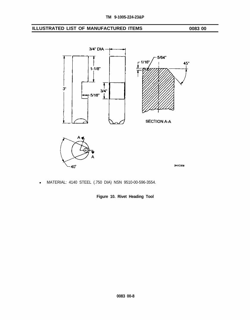
TM 9-1005-224-23&P
ILLUSTRATED LIST OF MANUFACTURED ITEMS 0083 00
MATERIAL: 4140 STEEL (.750 DIA) NSN 9510-00-596-3554.
Figure 10. Rivet Heading Tool
0083 00-8

TM 9-1005-224-23&P
FABRICATE FROM NSN 9510-00-813-5322.
USE DIMENSIONS ON ILLUSTRATION TO LAYOUT HANDLE.
CUT HANDLE OUT OF STOCK, THEN WELD TOGETHER.
Figure 11. Handle
0083 00-9

TM 9-1005-224-23&P
ILLUSTRATED LIST OF MANUFACTURED ITEMS 0083 00
FABRICATE FROM NSN 9510-00-542-2441
USE DIMENSIONS ON ILLUSTRATION TO LAYOUT FIXTURE.
CUT FIXTURE OUT OF STOCK AND MACHINE.
Figure 12. Fixture
0083 00-10

TM 9-1005-224-23&P
ASSEMBLE USING COMPONENTS MANUFACTURED IN FIGURES 11 AND 12.
USE DIMENSIONS ON ILLUSTRATION, AND POSITION HANDLE ONTO FIXTURE.
WELD HANDLE TO FIXTURE.
Figure 13. Drilling Fixture Assembly
0083 00-11/ 0083 00-12 blank


TM 9-1005-224-23&P
ALPHABETICAL INDEX 0084 00
SUBJECT WORK PACKAGE
AAdministrative Storage . . . . . . . . . . . . . . . . . . . . . . . . . . . . . . . . . . . . . . . . . . . . . . . . . . . . . . . . . . . . . . . WP 0021 00
CCharacteristics, Capabilities, and Features of Equipment . . . . . . . . . . . . . . . . . . . . . . . . . . . . . . . . . . WP 0002 00Corrosion Prevention and Control . . . . . . . . . . . . . . . . . . . . . . . . . . . . . . . . . . . . . . . . . . . . . . . . . . . . . . . . . . . . . . . . . . . . . . . . WP 0001 00
DDestruction of Army Materiel . . . . . . . . . . . . . . . . . . . . . . . . . . . . . . . . . . . . . . ..................................... WP 0001 00Differences Between Models . . . . . . . . . . . . . . . . . . . . . . . . . . . . . . . . . . . . . . . . . . . . . . . . . . WP 0002 00
EEquipment Characteristics, Capabilities, and Features ............................................... WP 0002 00Equipment Data ......................................................................................................... WP 0002 00Equipment Description and Data.. .............................................................................. WP 0002 00Equipment Improvement Recommendations (EIR), Reporting.. .................................. WP 0001 00Expendable/Durable Supplies and Materials List ........................................................ WP 0082 00
FFeatures, Capabilities, and Characteristics of Equipment ........................................... WP 0002 00
GGeneral Information .. . . . . . . . . . . . . . . . . . . . . . . . . . . . . . . . . . . . . . . . . . . . . . . . . . . . . . . . . . . . . . . . . . . WP 0001 00
IIllustrated List of Manufactured Items. . . . . . . . . . . . . . . . . . . . . . . . . . . . . . . . . . . . . . . . . . WP 0083 00
LLocation and Description of Major Components . . . . . . . . . . . . . . . . . . . . . . . . . . . WP 0083 00Lubrication ................................................................................................. WP 0020 00
MMaintenance Allocation Chart (MAC) . . . . . . . . . . . . . . . . . . . . . . . . . . . . . . . . . . . . . . . . . . WP 0048 00Maintenance Forms, Records, and Reports . . . . . . . . . . . . . . . . . . . . . . . . . . . . . . . . . . . . . . . . . . WP 0001 00Maintenance Procedures:
Direct Support: (General).
....................................................................
WP 0024 00Barrel and Bipod Assembly WP 0031 00Breech Bolt Assembly WP 0028 00Cocking Handle Assembly.. WP 0043 00Cover Assembly
.............................................................WP 0034 00
Cover Housing Assembly WP 0038 00Feed Cam Assembly.. ............................................................................. WP 0035 00Feed Lever Assembly.. ............................................................................ WP 0036 00Feed Pawl Assembly.. ............................................................................. WP 0037 00Forearm Assembly (M60 Only).
............................................................................WP 0039 00
Gun Receiver Assembly WP 0044 00Leaf Assembly (M60 Only) ...................................................................... WP 0041 00Machine Gun Bipod.. ............................................................................... WP 0032 00Machine Gun Legs.. ................................................................................ WP 0033 00M60 Machine Gun.. ................................................................................. WP 0025 00M60D Machine Gun ................................................................................ WP 0026 00Operating Rod Assembly.. ....................................................................... WP 0029 00Rear Sight (M60 Only). ............................................................................ WP 0040 00Rear Sight (M60D Only). ......................................................................... WP 0042 00Shoulder Gun Stock Assembly (M60 Only). ............................................. WP 0027 00Trigger Mechanism Grip Assembly (M60 Only). ....................................... WP 0030 00
Index-1

TM 9-1005-224-23&P
ALPHABETICAL INDEX (cont) 0084 00SUBJECT WORK PACKAGE
Maintenance Procedures (cont):Unit:
M (cont)
Barrel and Bipod Assembly . . . . . . . .Breech
. . . . . . . . . . . . . . . . . . . . . . . . . . . . . . . . . . . . . . . . . . . . . . . . . . . WP 0015 00Bolt Assembly . . . . . . . . . . . . . . . . . . . . . . . . . . . . . . . . . . . . . . . . . WP 0011 00
Cartridge Feed Tray Assembly (M60D Only) . . . . . . . . . . . . . . . . . . . . . . . . . . . WP 0018 00Cover Assembly . . . . . . . . . . . . . .Forearm Assembly (M60 Only) . .
................ . . . . . . . . . . . . . . . . WP 0016 00. . . . . . . . . . . . . . . . . . . . . . . . . . . . . . . . . . . . . . . . . . . . . . . . . . . . . WP 0019 00
Grip and Trigger Assembly (M60D Only) . . . . . . . . . . . . . . . . . . . . . . . . . . . . . . . . . . . . . . WP 0010 00M60 Machine Gun. . . . . . . . . . . . . . .M60D Machine Gun. . . . . . . .
. . . . . . . . . . . . . . . . . . . . . . . . . . . . . . . . . . . . . . . . . . . . . . . . . . . . . WP 0007 00
Operating. . . . . . . . . . . . . . . . . . . . . . . . . . . . . . . . . . . . . . . . . . . . . . . . . . .
Rod Assembly. . . . . . . . . . . . . . . . .WP 0008 00
. . . . . . . . . . . . . . . . . . . . . . . . . . . . . . . . . . . . . . . . .WP 0012 00Sear and Safety Housing Assembly (M60D Only) . . . . . . . . . . . . . . . . . . . . . . . . . . . . . . WP 0014 00Shoulder Gun Stock Assembly (M60 Only) . . . . . . . . . . . . . . . . . . . . . . . . . . . . . . . . . . . . . WP 0009 00Tray and Hanger Assembly and
Cartridge Feed Tray Assembly (M60 Only) . . . . . . . . . . . . . . . . . . . . . . . . . . . . . . . . . . . . WP 0017 00Trigger Mechanism Grip Assembly (M60 Only) . . . . . . . . . . . . . . . . . . . . . . . . . . . . . . . . . . WP 0013 00
PPreembarkation Inspection of Materiel in Units Alerted for Overseas MovementPreparation for Storage and Shipment:
......... WP 0045 00
Direct Support ................................Unit
.................................................................. WP 0046 00. . . . . . . . . . . . . . . . . . . . . . . . . . . . . . . . . . . . . . . . . . . . . . . . . . . . . . . . . . . . . . . . . . .
Preventive Maintenance Checks and Services (PMCS).WP 0021 00
. . . . . . . . . . . . . . . . . . . . . . . . . . WP 0005 00
RReferences . . . . . . . . . . . . . . . . . . . . . . . . . . . . . . . . . . . . . . . . . . . . . . . . . . . . . . . . . . . . .Repair Parts and Special Tools List..
WP 0047 00..........................
Repair Parts, Special Tools and Support Equipment:................................................ WP 0049 00
Direct SupportUnit
........................................................................................... WP 0022 00................................
Repening Equipment Improvement Recommendations (EIR)Reports, Records and Maintenance Forms.
.................................................................................. WP 0003 00WP 0001 00
.......................................................... WP 0001 00
SService Upon Receipt .........................................................Storage or Shipment, Preparation for:
....................................... WP 0004 00
Direct Support .......................................Unit
........................................................... WP 0046 00.................................................................................................... WP 0021 00
TTroubleshooting Procedures, Direct SupportTroubleshooting Procedures, Unit
. . . . . . . . . . . . . . . . . . . . . . . . . . . . . . . . . . . . WP 0023 00.............................................................................. WP 0006 00
Index-2

By Order of the Secretary of the Amy:
DENNJS J. REIMERGeneral, United States Army
Chief of Staff
Administrative Assistant to theSecretary of the Army
04713
DISTRIBUTION: TO be distr ibuted in accordance with the ini t ial distr ibut ionrequirements for IDN 401127 for TM 9-1005-224-23&P.

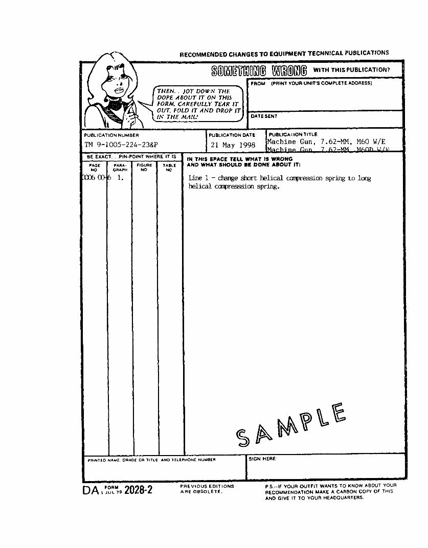


PIN: 076539-000

This fine document...
Was brought to you by me:
Liberated Manuals -- free army and government manuals
Why do I do it? I am tired of sleazy CD-ROM sellers, who take publicly available information, slap “watermarks” and other junk on it, and sell it. Those masters of search engine manipulation make sure that their sites that sell free information, come up first in search engines. They did not create it... They did not even scan it... Why should they get your money? Why are not letting you give those free manuals to your friends?
I am setting this document FREE. This document was made by the US Government and is NOT protected by Copyright. Feel free to share, republish, sell and so on.
I am not asking you for donations, fees or handouts. If you can, please provide a link to liberatedmanuals.com, so that free manuals come up first in search engines:
<A HREF=http://www.liberatedmanuals.com/>Free Military and Government Manuals</A>
– SincerelyIgor Chudovhttp://igor.chudov.com/
– Chicago Machinery Movers