Embed Size (px)
Citation preview

1
SUNFED OFF-GRID SINE WAVE SOLAR INVERTERS 1kW to 10kW
SUNFEDSUNFEDSUNFEDSUNFED Series
Technical Manual

Please read this manual carefully before installation and installed by qualified personnel to ensure careful installation. Those who operate the normal working Please preserve this manual carefully for future reference. This Technical Manual information about usage of equipmentinstaller/ supplier. This isinformation which is protected by copyright. All rights are reserved.
The following marks and signs will be used in this product manual.
Warning
Installation and equipment needs warnings given in this manual. Ignoring these endanger personal safety and cause to equipmentnormal operation. also be of the equipment unless you are qualified and trained to handle high voltage systemssafety, please let qualified personnel to this device. Caution
Charge battery for at least 12 hours before use. Verify rated power does not exceed rated power.
2
Preface
Please read this manual carefully before installation and operation. Equipment should be
by qualified personnel to ensure durable careful installation. Those who operate the
should be trained by the installer. Please preserve this manual carefully for future
Technical Manual contains detailed about the installation, operation and
usage of equipment to guide and benefit the installer/ supplier. This is a proprietary information which is protected by copyright. All rights are reserved.
Markings
The following marks and signs will be used in this product manual.
Warning Installation and Operation of this equipment needs one to follow the warnings given in this manual. Ignoring these instructions will endanger installer’s and user’s personal safety and cause damage
equipment and prevent it’s normal operation. The data may also be lost. Do not remove covers of the equipment unless you are qualified and trained to handle high voltage systems. For your safety, please let qualified personnel to install and operate this device.
Caution Charge battery for at least 12 hours before use. Verify Inverter’s rated power does not exceed its rated power.

3
Content
1 PRODUCT INTRODUCTION ......................................................................................... 4
2 SCHEMATIC DIAGRAM ................................................................................................... 5
3 SPECIFICATION .................................................................................................................. 6
4 UNPACKING ........................................................................................................................ 7
5 INSTALLATION ................................................................................................................... 8
5.1 PLACEMENT OF INVERTER……………………………………………………………………………..8 5.2 VENTILATION ........................................................................................................................... 8 5.3 MAXIMUM WORKING CURRENT & RECOMMEND CABLE CONNECTION ........................... 8 5.4 BACK PANEL ............................................................................................................................. 9 5.5 BATTERY CONNECTION ........................................................................................................... 9 5.6 SOLAR CONTROLLER CONNECTION ..................................................................................... 10
6 OPERATION ....................................................................................................................... 12
6.1 CONTROL PANEL ......................................................................................................................... 6.2 OPERATION INTERFACE-LCD DISPLAY 6.3 WORKING MODE 6.4 TEST 6.5 LAUNCH 6.6 STOP OUTPUT UNDER CITY POWER MODE 6.7 SHUTDOWN UNDER BATTERY MODE 6.8 ADJUST CHARGING CURRENT(OPERATING IN CITY POWER MODE)
7 OPERATION INTERFACE INSTRUCTION................................................................ 14
8 SECURITY ............................................................................................................................ 15
9 TROUBLESHOOTING ..................................................................................................... 17
10 BATTERY MAINTENANCE ............................................................................................ 17
11 WARRANTY ....................................................................................................................... 18

4
1 Product Introduction
The new Range of SUNFED Sine-wave Solar Inverters from MITRAMAX ENERGY are based on the carefully developed technology that enables harvesting of 10 to 15% more solar energy than conventional Inverters. SUNFED Solar inverter uses efficient torroid-cored output transformer and high 90% efficiency which ensures peak production while providing simplified system planning, long endurance and maintenance free operation. SUNFED Inverters can be integrated into any off-grid power systems up to 10kW in size.
Efficient • Maximum efficiency 90% • Very low no load losses • Intelligent battery management
Simple
• Easy and Quick commissioning • Complete off-grid management • Excellent for grid power and battery back-up, wherever grid power is
available Flexible
• For SUNFED systems from 1kW to 10kW • Ideal to go with Sun any place; deserts, forests and hinterlands
Durable
• Extreme overload capability • Active thermal management system • Two-year standard warranty
1kW to 10kW SUNFED SOLAR INVERTERs from MITRAMAX ENERGY offer first class possibilities in the installation of self-sufficient energy system. In conjunction with a battery pack they offer an independent source of stable 230V AC, for homes and offices, which meets with the highest quality standards. They are designed to deliver pure Solar Energy at any point under the Sun. Their unique design integrates Line Power, if available, as a backup source. SUNFED System offers a high degree of flexibility at system planning and layout. Computers, TVs, Home Appliances and other products last longer and run better when powered with true sine-wave electricity. Our embedded solar chargers use multiple stages to perform quick recharging while prolonging battery life, saving batteries from unnecessary wear and prolonging their life on these costly components of the energy system. Rugged construction and simplified design deliver industry-leading reliability, an important

5
consideration for those seeking an energy independent lifestyle. For Use anywhere under the Sun; with or without Grid Supply
The SUNFED Series Solar Inverters are designed for use anywhere, even in hinterlands and jungles where there is no electric supply, SUNFED converters Sun’s Energy into 230V AC Supply. AC Line Back up to Inverter
SUNFED series Solar Inverters can be used anywhere, whether Line AC Power is available or not. But if it is available, SUNFED Solar Inverters have a facility to automatically switch the load from Inverter to commercial AC line in case battery and/or sun energy is not available, as standby measure to power your load without interruption giving break-less AC power to your loads. AC Line Voltage Regulation
SUNFED Inverter System not only feeds your load from line but also regulates to give stable output voltage with an electronic tap change with maximum break of less than 3msec during tap change.
External Data Communication
As an optional function, SUNFED series inverter communicates with local net servers and other computer system via RS232 communication sockets. RS232 socket provides information for main computer, such as voltage, current, temperature and frequency with UPSilon2000 power management software.
2 Schematic Diagram
SUNFED
Inverter
(Bi-directional)
AC
Line Power
Line In User
LOAD
BATTERY
Tap Changer
Line Voltage
PV
Solar
Array

6
SUNFED INVERTER FEATURES
A. SUNFED Inverters work primarily from a battery and start even when commercial line supply is available or otherwise. Therefore these are also ideal for use in remote locations away from electrified areas like cities and towns
B. Depending on its power rating in kVA, SUNFED Inverter feeds pure sine-wave power to a wide variety of electrical and electronic products. For example, home appliances like filament lamp, LED light, energy saving lamp, electric water heater, electric oven, electric cooker, electric tea kettle, washing machine, refrigerator, ceiling and table fans besides office equipment like computers, servers, copiers and other office appliances. TV, game machines etc. It can also feed Air-conditioners and motor loads of appropriate rating.
C. SUNFED Solar Inverters use extensive microcomputer control technique to ensure high performance.
D. SUNFED Solar Inverter circuit is unique, same circuitry works like and inverter as wells as a battery charger!
E. Protections for overload, short circuit, over voltage, under voltage and overheating ensure High reliability.
F. Modularized circuit PCB design for easy installation and field-maintenance. G. Instant auto-sensing and auto-adjustable chargers for optimized battery
performance and prolonged battery longevity. H. Efficient toroidal transformer at lowest energy loss
3 Technical Specifications
SUNFED Series SINESUNFED Series SINESUNFED Series SINESUNFED Series SINE----WAVE HYBRID SOLAR INVERTER 1kVA to 10kVAWAVE HYBRID SOLAR INVERTER 1kVA to 10kVAWAVE HYBRID SOLAR INVERTER 1kVA to 10kVAWAVE HYBRID SOLAR INVERTER 1kVA to 10kVA
Rated output capacity in
KVA 1kVA 2kVA 3kVA 5kVA 10kVA
Peak Power capacity 800W 1.6kW 2.4kW 4kW 8kW
Nominal Battery voltage(DC) 24V 48V 96V 192V
Solar Priority Operating Mode Logic
• Normally works as a Solar Inverter working from Solar Energy or Battery
• When Battery voltage, on load, drops to its under voltage limit, line power is turned on to feed the load and also charge battery from power line
PV Solar Modules 900Wp 1500Wp 3000Wp 5000Wp 10,000Wp
MPPT Current Controller Built-in every LEECH PV Module
Min Solar Energy Generation on a Sunny Day
5KWH 10kWH 15kWH 30kWH
AC Input Voltage(AC) 165V~275V (Mains mode)
Frequency 50Hz±5Hz
Output(AC) Voltage 230V±3% (Inverter Mode)
Frequency 50Hz±1%
Solar Input (solar intensity dependent)
22A 25A 38A 32A 32A
Battery Charger Charge 1~20A –Auto-detect real-time, self-setting

7
4 Unpacking
The unit is packed very carefully in order to avoid possible damage during transportation. Please check that the packing is in good condition before initial use. Please contact with your supplier immediately if there is any damage on inverter. On unpacking check that there are following enclosed: • A unit of inverter • A power cable • A user manual • A management software (if communication function is ordered) If there is any damage caused by transportation, please return the unit to distributor for repairing or replacement.
Current
Charge time 8~16 hours
Battery protection
Automatic self-test. Charge and Discharge Level Protection
Display Mode Graphic Bright LED
Information shown
Input and Output Voltage, Frequency, Battery capacity, load Level,
Output wave type Pure Sine wave (THD ≤3)
Overload capacity 120% for 60s, 130% for 10s
Inverter efficiency 90% max/ 87% average
No Load DC Input Current Less than 1% of the Full load Input DC Current
Transfer time to Mains ≤3ms
Protections
I. Output overload, short-circuit II. Battery reverse polarity, III. Input high/low voltage protection , IV. Overheat protection;
Safety Approvals: CE and EMC
Using environment
Temperature -10°C to +50°C
Humidity 10%~90%, Non-condensing
Altitude ≤4000m
Size W×D×H(mm) 450x180x320 460x250x400
Net weight (kg) 18 20 22 38 46

5 Installation
Danger
Our equipment should be installed according to local safety
standard by qualified and professional personnel
5.1 Placement of Inverter
The Inverter should be installed vertically on the ground or proper temperature and humidity. Do not pile up other inverter case. The Inverter’s normal ambient cool shaded place inside home or office. The battery lifespan will be affected 10°C increase, expected service life will 5.2 Ventilation
The device should be placed at a good office environment to
• Make sure that no obstacle is at the vent.• Keep away from hot source and avoid of sun shining directly.• Avoid of dust and dampness.• Please place it at a good ventilated environment.
and all the round of equipmenair.
5.3 Maximum working current & recommend cable
The following table is the recommended cable diameter
Inverter Rating in kVA
Max Input Current
Input Wire Size (mm²)
Solar array to Inverter
Ground connect wire
Requirements of the cable type:
1. PVC insulated copper core cable.2. The cable can be thicker if the exact size is not available
8
Our equipment should be installed according to local safety
standard by qualified and professional personnel.
Placement of Inverter
should be installed vertically on the ground or on a strong proper temperature and humidity. Do not pile up other materials on the
Inverter’s normal ambient temperature is 0°C to 40°C maximum. So place icool shaded place inside home or office. The battery lifespan will be affected when temp rises above 25°C after that
expected service life will decrease.
The device should be placed at a good office environment to avoid of damage.
Make sure that no obstacle is at the vent. Keep away from hot source and avoid of sun shining directly. Avoid of dust and dampness. Please place it at a good ventilated environment. Leave 20cm (8”) and all the round of equipment for effective cooling and escape of
Maximum working current & recommend cable size
The following table is the recommended cable diameter
1 2 3 5
4A 8A 12A 20A
0.75 2 3 4
Size depends on the distance from Array to Inverter
0.75 0.75 1 2
Requirements of the cable type:
PVC insulated copper core cable. The cable can be thicker if the exact size is not available
Our equipment should be installed according to local safety
on a strong shelf in the on the top of the
0°C to 40°C maximum. So place it in a
when temp rises above 25°C after that every
avoid of damage.
(8”) gap at top for effective cooling and escape of exhaust
10
20A
4
Size depends on the distance from Array to Inverter
2

9
Rear Panel Layouts
1kVA Rear View
2kVA & 3kVA Rear View

5.4 Battery Connection
Danger
Inverter 5KVA and below has no
Please make sure to connect the batteries correctly. Otherwise, the devices will
1. To connect inverter to a chosen Battery and the PV Solar Module
to following schematic:
System Schematic of SUNFED Solar Inverters
AC
Line In
10
5kVA-10kVA Rear View
Inverter 5KVA and below has no battery anti-polarity protection.
to connect the batteries correctly. Otherwise, the devices will
be damaged immediately.
to a chosen Battery and the PV Solar Module, pleased refer to following schematic:
System Schematic of SUNFED Solar Inverters
SUNFED
Inverter
(Bi-directional)
User
LOAD
BATTERY
Transfer Switch Transfer Time < 3msec
Photo
Voltaic Solar
Array
Array
polarity protection.
to connect the batteries correctly. Otherwise, the devices will
, pleased refer
11
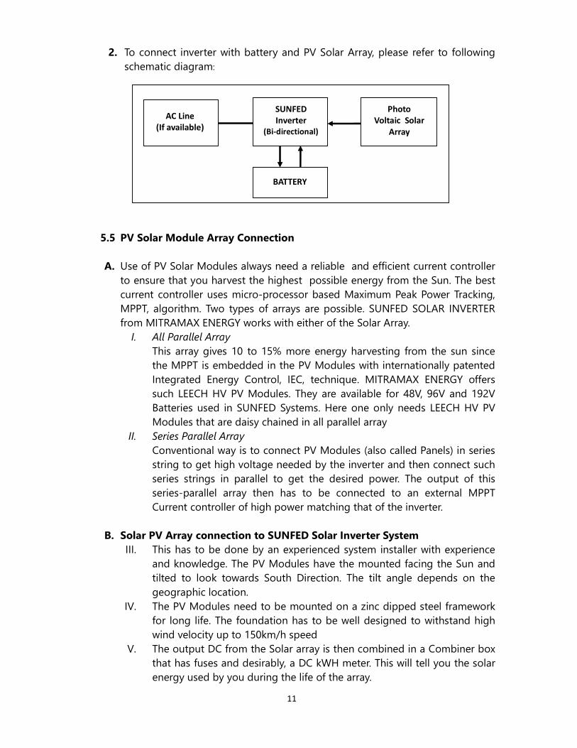
2. To connect inverter with battery and PV Solar Array, please refer to following schematic diagram:
5.5 PV Solar Module Array Connection
A. Use of PV Solar Modules always need a reliable and efficient current controller to ensure that you harvest the highest possible energy from the Sun. The best current controller uses micro-processor based Maximum Peak Power Tracking, MPPT, algorithm. Two types of arrays are possible. SUNFED SOLAR INVERTER from MITRAMAX ENERGY works with either of the Solar Array.
I. All Parallel Array
This array gives 10 to 15% more energy harvesting from the sun since the MPPT is embedded in the PV Modules with internationally patented Integrated Energy Control, IEC, technique. MITRAMAX ENERGY offers such LEECH HV PV Modules. They are available for 48V, 96V and 192V Batteries used in SUNFED Systems. Here one only needs LEECH HV PV Modules that are daisy chained in all parallel array
II. Series Parallel Array
Conventional way is to connect PV Modules (also called Panels) in series string to get high voltage needed by the inverter and then connect such series strings in parallel to get the desired power. The output of this series-parallel array then has to be connected to an external MPPT Current controller of high power matching that of the inverter.
B. Solar PV Array connection to SUNFED Solar Inverter System
III. This has to be done by an experienced system installer with experience and knowledge. The PV Modules have the mounted facing the Sun and tilted to look towards South Direction. The tilt angle depends on the geographic location.
IV. The PV Modules need to be mounted on a zinc dipped steel framework for long life. The foundation has to be well designed to withstand high wind velocity up to 150km/h speed
V. The output DC from the Solar array is then combined in a Combiner box that has fuses and desirably, a DC kWH meter. This will tell you the solar energy used by you during the life of the array.
SUNFED
Inverter
(Bi-directional)
AC Line
(If available)
BATTERY
Photo
Voltaic Solar
Array
Array

12
VI. Output from the Combiner box is then connected to the SUNFED SOLAR INVERTER System to +ve and –ve PV SOLAR INPUT Terminals respectively.
VII. One has to use proper size of copper cable in mm² size to ensure that there is minimum loss of energy in voltage drop in the connecting cable.
C. Solar Priority Energy Use
D. The Software in the SUNFED Solar Inverter system ensures that all the solar energy produced by you is used first. The second priority is the energy stored in the battery when the Sun is not there. The last option is the Commercial Line Power.
Solar power Presence
City power Presence
Inverter Draw of Energy and Battery charging
YES YES SOLAR
NO YES CITY POWER
YES NO SOLAR
NO NO NOT CHARGE
NOTE: if “SOLAR CHARGE SWITCH” is off, the inverter cannot check whether the solar controller charges battery or not. Therefore, if the battery capacity is not full, the inverter will charge battery automatically whatever solar controller runs or not.
6 Operation
6.1 Control panel
ON & Mute buttons: � For Turning the unit ON
Keep pressing this button for 2 seconds until you hearing the prompt beep; after that the system turns ON.
� For silencing Alarm
� Keep pressing this button for 1 second until alarm becomes silent. OFF & Function button:

� Keep pressing this button to turn off� Keep pressing this button for 4 seconds and the screen will display the operation
interface of adjusting charging current.6.2 Operation Interface-LCD display
1. Input voltage indicator2. Frequency indicator 3. Output voltage indicator4. Battery capacity or charging indicator5. Normal status indicator6. Abnormal condition indicator7. Inverting status indicator8. Overload indicator 9. Load utilization ratio indicator
6.3 Solar Priority Operational
� BATTERY MODE (Normal mode)
SUNFED Solar Inverter alwayconnecting the Battery it will not work. In this mode Inverter will primarily draw all its power from Sun. If the Sun is weak or not available it will work from the energy stored from the battery. The display wiINPUT VOLTAGE if external Line Supply is absent or failed. If line is available it will display the line voltage but it will not be drawing power from the commercial line.
� AC LINE SUPPLY MODE (Abnormal Mode)
When both Solar and Battery Powavailable; it provide Meanwhile, when the the inverter will choose feeding your load.
6.4 Preliminary Test
Please don’t connect high load whileIf it beeps every 1sec, it means that the battery is to be empty; the inverter will turn off soon.
6.5 Starting
� Turn on the inverter with Battery
1. Turn on the external battery2. Press the button “POWER ON” on the front panel for 3sec3. It will take about 4. Turn on the loads
Warning
If the inverter is overloaded, the buzzer will beep. Please reduce the
the load and follow the instruction of user manual.
13
Keep pressing this button to turn off Inverter will turn off in 2 seconds.Keep pressing this button for 4 seconds and the screen will display the operation interface of adjusting charging current.
LCD display
1. Input voltage indicator
3. Output voltage indicator or charging indicator
5. Normal status indicator 6. Abnormal condition indicator 7. Inverting status indicator
9. Load utilization ratio indicator
Solar Priority Operational Mode
(Normal mode)
SUNFED Solar Inverter always starts working from the battery. Without connecting the Battery it will not work. In this mode Inverter will primarily draw all its power from Sun. If the Sun is weak or not available it will work from the energy stored from the battery. The display will show “0” for INPUT VOLTAGE if external Line Supply is absent or failed. If line is available it will display the line voltage but it will not be drawing power from the
AC LINE SUPPLY MODE (Abnormal Mode)
When both Solar and Battery Power is not available and if the city power is provide power to the load to ensure that there is no blackout.
Meanwhile, when the Sun is shining and the charged battery the inverter will choose this green energy as the priority power supply
high load while in initial testing status. If it beeps every 1sec, it means that the battery is to be empty; the inverter will
with Battery Connected
Turn on the external battery Press the button “POWER ON” on the front panel for 3sec It will take about 30sec for output AC Voltage to be stable Turn on the loads
If the inverter is overloaded, the buzzer will beep. Please reduce the
the load and follow the instruction of user manual.
2 seconds. Keep pressing this button for 4 seconds and the screen will display the operation
s starts working from the battery. Without connecting the Battery it will not work. In this mode Inverter will primarily draw all its power from Sun. If the Sun is weak or not available it will work
ll show “0” for INPUT VOLTAGE if external Line Supply is absent or failed. If line is available it will display the line voltage but it will not be drawing power from the
he city power is to the load to ensure that there is no blackout.
battery is available, power supply
If it beeps every 1sec, it means that the battery is to be empty; the inverter will
If the inverter is overloaded, the buzzer will beep. Please reduce the amount of
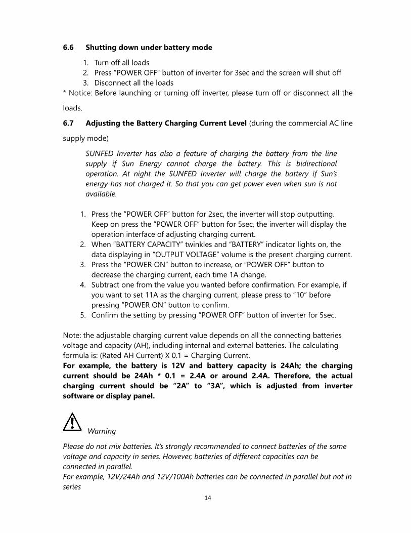
6.6 Shutting down under battery mode
1. Turn off all loads 2. Press “POWER OFF” button of inverter for 3sec and the screen will shut off3. Disconnect all the loads
* Notice: Before launching or turning off
loads.
6.7 Adjusting the Battery Charging Current Level
supply mode)
SUNFED Inverter has also a feature of charging the battery from the line
supply if Sun Energy cannot charge the battery. This is bidirectional
operation. At night the SUNFED inverter will charge the battery if Sun’s
energy has not charged it. So that you can get power even when sun is not
available.
1. Press the “POWER OFF” button for
Keep on press the “POWER OFF” button for 5sec, the inverter will display the operation interface of adjusting charging current.
2. When “BATTERY CAPACITY” twinkles and “BATTERY” indicator lights on, the data displaying in “OUTPUT VOLTAGE” volume is the present charging current.
3. Press the “POWER ON” button to increase, or “POWER OFF” button to decrease the charging current, each time 1A change.
4. Subtract one from the value you wanted before confirmation. For example, if you want to set 11A as the charging current, please press to “10” before pressing “POWER ON” button to confirm.
5. Confirm the setting by pressing “POWER OFF” button of inverter for 5sec. Note: the adjustable charging current value depends on all the connectvoltage and capacity (AH), including internal and external batteries. The calculating formula is: (Rated AH Current) For example, the battery is 12V and battery capacity is 24Ah; the charging
current should be 24Ah * 0.1 = 2.4A or around 2.4A. Therefore, the actual
charging current should be “2A” to “3A”, which is adjusted from inverter
software or display panel.
Warning
Please do not mix batteries. It’s strongly recommended to connect batteries of the same
voltage and capacity in series. However, batteries of different capacities can be
connected in parallel.
For example, 12V/24Ah and 12V/100Ah batteries can be connected in parallel but not in
series
14
down under battery mode
Press “POWER OFF” button of inverter for 3sec and the screen will shut offDisconnect all the loads Before launching or turning off inverter, please turn off or disconnect all the
Adjusting the Battery Charging Current Level (during the commercial AC line
SUNFED Inverter has also a feature of charging the battery from the line
Sun Energy cannot charge the battery. This is bidirectional
operation. At night the SUNFED inverter will charge the battery if Sun’s
energy has not charged it. So that you can get power even when sun is not
Press the “POWER OFF” button for 2sec, the inverter will stop outputting. Keep on press the “POWER OFF” button for 5sec, the inverter will display the operation interface of adjusting charging current. When “BATTERY CAPACITY” twinkles and “BATTERY” indicator lights on, the
g in “OUTPUT VOLTAGE” volume is the present charging current.Press the “POWER ON” button to increase, or “POWER OFF” button to decrease the charging current, each time 1A change. Subtract one from the value you wanted before confirmation. For example, if you want to set 11A as the charging current, please press to “10” before pressing “POWER ON” button to confirm. Confirm the setting by pressing “POWER OFF” button of inverter for 5sec.
Note: the adjustable charging current value depends on all the connecting batteries voltage and capacity (AH), including internal and external batteries. The calculating
Current) X 0.1 = Charging Current. For example, the battery is 12V and battery capacity is 24Ah; the charging
* 0.1 = 2.4A or around 2.4A. Therefore, the actual
charging current should be “2A” to “3A”, which is adjusted from inverter
Please do not mix batteries. It’s strongly recommended to connect batteries of the same
voltage and capacity in series. However, batteries of different capacities can be
For example, 12V/24Ah and 12V/100Ah batteries can be connected in parallel but not in
Press “POWER OFF” button of inverter for 3sec and the screen will shut off
inverter, please turn off or disconnect all the
(during the commercial AC line
SUNFED Inverter has also a feature of charging the battery from the line
Sun Energy cannot charge the battery. This is bidirectional
operation. At night the SUNFED inverter will charge the battery if Sun’s
energy has not charged it. So that you can get power even when sun is not
2sec, the inverter will stop outputting. Keep on press the “POWER OFF” button for 5sec, the inverter will display the
When “BATTERY CAPACITY” twinkles and “BATTERY” indicator lights on, the g in “OUTPUT VOLTAGE” volume is the present charging current.
Press the “POWER ON” button to increase, or “POWER OFF” button to
Subtract one from the value you wanted before confirmation. For example, if you want to set 11A as the charging current, please press to “10” before
Confirm the setting by pressing “POWER OFF” button of inverter for 5sec.
ing batteries voltage and capacity (AH), including internal and external batteries. The calculating
For example, the battery is 12V and battery capacity is 24Ah; the charging
* 0.1 = 2.4A or around 2.4A. Therefore, the actual
charging current should be “2A” to “3A”, which is adjusted from inverter
Please do not mix batteries. It’s strongly recommended to connect batteries of the same
voltage and capacity in series. However, batteries of different capacities can be
For example, 12V/24Ah and 12V/100Ah batteries can be connected in parallel but not in
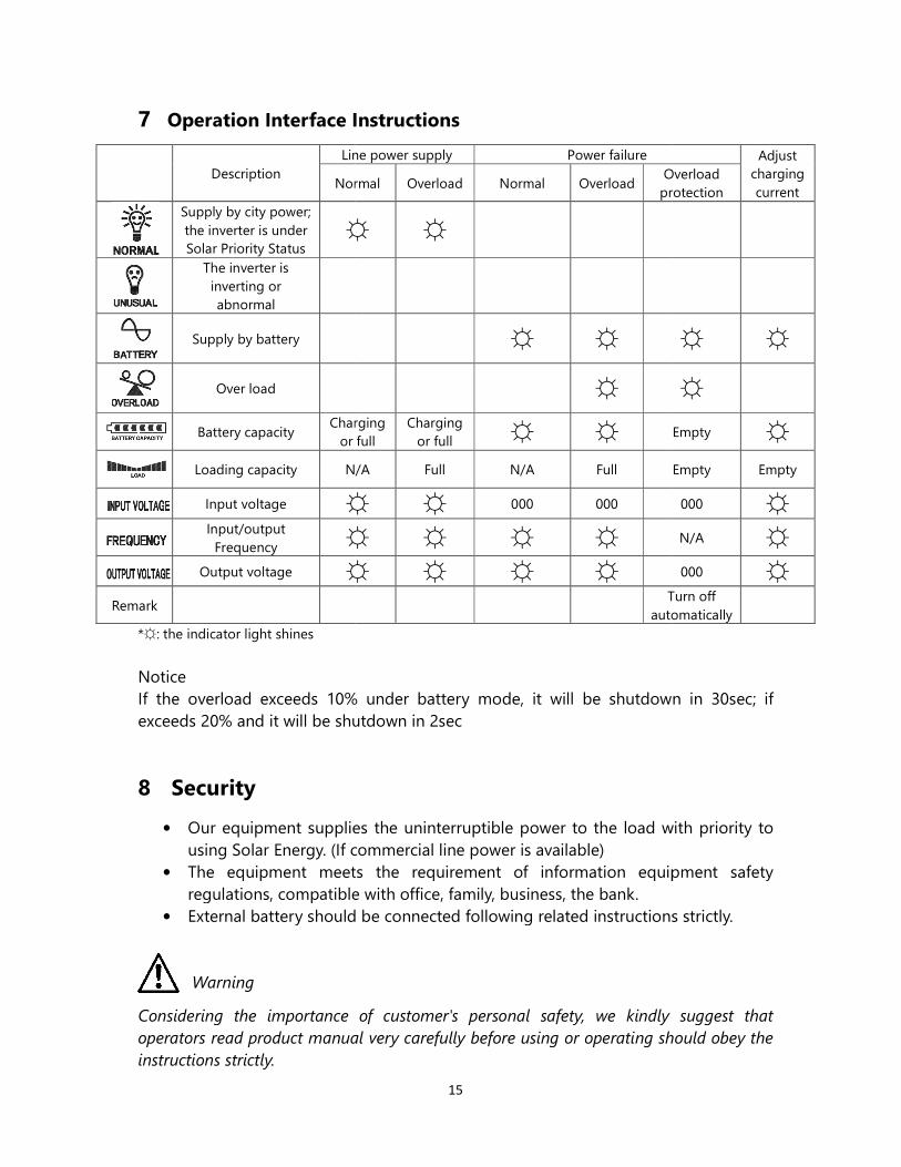
7 Operation Interface Instruction
Description
Line
Normal
Supply by city power; the inverter is under Solar Priority Status
☼
The inverter is inverting or abnormal
Supply by battery
Over load
Battery capacity Charging
or full
Loading capacity N/A
Input voltage ☼
Input/output
Frequency ☼
Output voltage ☼
Remark
*☼: the indicator light shines
Notice If the overload exceeds 10% under battery mode, it will be shutdown in 30sec; if exceeds 20% and it will be shutdown in 2sec
8 Security
• Our equipment supplies the uninterruptible using Solar Energy. (If commercial line power is available)
• The equipment meets the requirement of information equipment safety regulations, compatible with office, family, business, the bank.
• External battery should be c Warning
Considering the importance of customer's personal safety, we kindly suggest that
operators read product manual very carefully before using or operating should obey the
instructions strictly.
15
Operation Interface Instructions
Line power supply Power failure
Normal Overload Normal Overload Overload
protection
☼ ☼
☼ ☼
☼ Charging
or full Charging
or full ☼ ☼
N/A Full N/A Full
☼ ☼ 000 000
☼ ☼ ☼ ☼ ☼ ☼ ☼ ☼
Turn off
automatically
If the overload exceeds 10% under battery mode, it will be shutdown in 30sec; if exceeds 20% and it will be shutdown in 2sec
Our equipment supplies the uninterruptible power to the load with priority to (If commercial line power is available)
The equipment meets the requirement of information equipment safety regulations, compatible with office, family, business, the bank. External battery should be connected following related instructions strictly.
Considering the importance of customer's personal safety, we kindly suggest that
operators read product manual very carefully before using or operating should obey the
Adjust charging current
Overload protection
☼ ☼
☼
Empty ☼
Empty Empty
000 ☼
N/A ☼
000 ☼
Turn off automatically
If the overload exceeds 10% under battery mode, it will be shutdown in 30sec; if
with priority to
The equipment meets the requirement of information equipment safety
onnected following related instructions strictly.
Considering the importance of customer's personal safety, we kindly suggest that
operators read product manual very carefully before using or operating should obey the

There is a danger of high voltages in the unit even if all the switches are turned
off. Any operation to move or open the equipment should be performed by
"authorized professional personnel"
Battery voltage is DC and all DC voltages above 50V are dan
deadly shock. So ask only a trained person to touch the battery.
To ensure safety, please follow safety precaution terms:• Please read this manual • In case of any problems with the equipment, please cut off the electricity as
soon as possible, and contact • If there's a fire on the machine, please use dry powder extinguisher to put out
the fire but not the water.• There's no switch for cutting off the
recommend you to use wall socket that has on/off switch. • Do not place any container with liquid on the equipment in order to avoid
moisture/water entry circuit, chance of electrocution and
• This equipment should be connected to the earth for
Important Safety Instruction
• Check that the inverter connects to the earth.• The unit is not recommended for hu
equipment. • Don’t locate inverter near magnetic materials. It may result data lost.
Emergency
Danger
Before connecting with load, please ensure that all the equipment is in off condition.
Electric leakage
Danger
Be sure to connect the earth wire before the connection of other wires.
16
There is a danger of high voltages in the unit even if all the switches are turned
off. Any operation to move or open the equipment should be performed by
"authorized professional personnel" only.
Battery voltage is DC and all DC voltages above 50V are dangerous and can give
deadly shock. So ask only a trained person to touch the battery.
Safety precautions
To ensure safety, please follow safety precaution terms: Please read this manual in details, do not load over the rated level.In case of any problems with the equipment, please cut off the electricity as soon as possible, and contact your maintenance agency immediately.If there's a fire on the machine, please use dry powder extinguisher to put out the fire but not the water.
re's no switch for cutting off the Line Power on the equipment, we strongly use wall socket that has on/off switch.
Do not place any container with liquid on the equipment in order to avoid inside the equipment. It will cause equipment short
electrocution and a danger of fire. This equipment should be connected to the earth for full safety.
Check that the inverter connects to the earth. The unit is not recommended for human’s life support system and highly critical
Don’t locate inverter near magnetic materials. It may result data lost.
Before connecting with load, please ensure that all the equipment is in off condition.
Be sure to connect the earth wire before the connection of other wires.
There is a danger of high voltages in the unit even if all the switches are turned
off. Any operation to move or open the equipment should be performed by
gerous and can give
details, do not load over the rated level. In case of any problems with the equipment, please cut off the electricity as
immediately. If there's a fire on the machine, please use dry powder extinguisher to put out
wer on the equipment, we strongly
Do not place any container with liquid on the equipment in order to avoid cause equipment short
man’s life support system and highly critical
Don’t locate inverter near magnetic materials. It may result data lost.
Before connecting with load, please ensure that all the equipment is in off condition.
Radio frequency interference
This device can interfere radio products. Please keep away from electromagnet interference sensitive products, such as transmitter, receiver, sure to keep away from the equipment.
9 Troubleshooting
If there is any abnormity to equipment, please check as following before contacting our customer service representative:• Whether external battery is connected properly to +ve
batteries used are in good charged condition• The Commercial Line Supply may or may not be available. SUNFED is Solar Inverter
that can work from just the battery which is charged from the SUN’s free Energy. So it is ideal for use anywhere, w
10 Battery Maintenance
SUNFED SOLAR Inverters require little routine maintenance.
1. Where ever commercial line supply is available and whether “OFF”, the battery is alwaypriority, or line AC power if available. This ensures the battery is always kept fully charged and it is protected with over charge and over discharge protection function.
2. Before initially launching the inhours to make sure that they are fully charge.
3. If you do not use inverter for a long time or backup battery discharge occasionally, please charge and discharge the battery every 3 to 6 months; in hot area, please charge and discharge the battery once every two months, with charging time not less than 12 hours.
4. Due to built-in protection against deep discharge or over charge, circumstances, the battery life is three to five years. If the battery iscondition, please replace it as soon as possible by qualified personnel.
5. Please replace the battery with the same Please do not change a single battery separately; the battery replacement should be strictly followed by supplier's instructions.
Warning
1. Battery voltage is DC and all DC voltages above 50V are dangerous and
can give deadly shock. So ask only a trained person to touch the battery.
2. Replace the battery cable connected from battery to inverter with size cable in
17
Radio frequency interference
This device can interfere radio products. Please keep away from electromagnet interference sensitive products, such as transmitter, receiver, radar, metal detector, be sure to keep away from the equipment.
If there is any abnormity to equipment, please check as following before contacting our customer service representative:
Whether external battery is connected properly to +ve & -ve terminals and the batteries used are in good charged condition The Commercial Line Supply may or may not be available. SUNFED is Solar Inverter that can work from just the battery which is charged from the SUN’s free Energy. So
nywhere, whether the city line power supply is available or not!
Battery Maintenance
require little routine maintenance.
Where ever commercial line supply is available and whether inverter is “ON” or “OFF”, the battery is always being charged either from the solar energy, as a priority, or line AC power if available. This ensures the battery is always kept
it is protected with over charge and over discharge protection
Before initially launching the inverter, please charge the batteries at least 12 hours to make sure that they are fully charge. If you do not use inverter for a long time or backup battery discharge occasionally, please charge and discharge the battery every 3 to 6 months; in
ease charge and discharge the battery once every two months, with charging time not less than 12 hours.
in protection against deep discharge or over charge, ucircumstances, the battery life is three to five years. If the battery iscondition, please replace it as soon as possible by qualified personnel. Please replace the battery with the same capacity and quantity.
Please do not change a single battery separately; the battery replacement should be strictly followed by supplier's instructions.
Battery voltage is DC and all DC voltages above 50V are dangerous and
can give deadly shock. So ask only a trained person to touch the battery.
cable connected from battery to inverter with size cable in
This device can interfere radio products. Please keep away from electromagnet radar, metal detector, be
If there is any abnormity to equipment, please check as following before contacting
ve terminals and the
The Commercial Line Supply may or may not be available. SUNFED is Solar Inverter that can work from just the battery which is charged from the SUN’s free Energy. So
supply is available or not!
inverter is “ON” or ed either from the solar energy, as a
priority, or line AC power if available. This ensures the battery is always kept it is protected with over charge and over discharge protection
verter, please charge the batteries at least 12
If you do not use inverter for a long time or backup battery discharge occasionally, please charge and discharge the battery every 3 to 6 months; in
ease charge and discharge the battery once every two months, with
under normal circumstances, the battery life is three to five years. If the battery is not in good condition, please replace it as soon as possible by qualified personnel.
Please do not change a single battery separately; the battery replacement should be
Battery voltage is DC and all DC voltages above 50V are dangerous and
can give deadly shock. So ask only a trained person to touch the battery.
cable connected from battery to inverter with size cable in

18
mm² and good insulation 3. Avoid battery short circuit, otherwise it will cause fire disaster or electric shock. 4. Before touching the battery, please make sure that there is no voltage. Battery
circuit loop and input voltage loop are not isolated; there might be high voltage between battery terminals and the ground.
5. Even if the input power is switched off, the internal components of inverter might still be connected to the battery with potential danger. Therefore, before doing any repair or maintenance work, please disconnect or unplug the battery.
1) Battery has the danger of high voltage. Battery maintenance should be
operated by qualified personnel with proper battery knowledge.
11 Warranty
We offer free service during warranty period if the unit is returned to our offices with proper roadworthy packing. Service is free for 12 months from the date of sale; except when the problems are caused by faulty installation, poor maintenance and human factors like negligent misuse. Operating Environment should be within the specified limit.
Mitramax Energy Private Limited Deodhar Centre, 424, Marol Maroshi Road, Andheri East, Mumbai 400059
Tel: +912228290255 Webpage: www.mitramax.com In Europe: Mitramax Energy GmbH. Putzbrunn, Germany