Embed Size (px)
Citation preview

TECHNICAL MANUAL


PG / 6 800.543.6618
CONTENTS
*NOTE: When service or replacement parts are required, please contact your local Pro-Cut Representative through either the SuperTech app or through our website: www.procutusa.com
Limited WarrantyLathe Overview / ComponentsBrake Lathe SpecificationsList of Standard AccessoriesAcceptance from CarrierSafety InformationAssembly of LatheOperations ProceduresMulti-Speed SettingsSet Up for Rotors or Drum Cutting
910/111213141419202021
Machining Hub-less and Hubbed DrumsDetailed Instructions Mounting Hubbed Drums or RotorsCommand Module - Machining Mode Command Module - Set-Up ModeCommand Module - Statistics ModeAdvanced TipsDiagramsMaintenance Schedule
222324272829303146

WWW.PROCUTUSA.COM PG / 7
OUR MISSIONPro-Cut International is dedicated to providing our customers with the most advanced, precise, and profitable tools for brake repair. We have worked with, learned from and solved problems for people at all levels of the brake repair business - from the largest auto manufacturers and national service chains to one-bay, one-man operations. It is a business our entire staff lives, eats, and breathes. We welcome you to our table and look forward to working with you to im-prove your brake service business.
PG / 8 800.543.6618
You have just purchased what we feel is the finest bench brake lathe in the world. Your Pro-Cut B17 is a high quality, precision engineered product designed to give you years of trouble free service. To familiarize yourself with all its features, please take the time to read this owner’s manual carefully and store this manual in a safe place for future reference.
Our job is not done until you feel your technician team was trained properly and received all the information needed to operate the B17 efficiently, accurately, and above all, SAFELY.
Your warranty will begin once you sign off that you are happy with the training.
For Records and Information:
CONGRATULATIONS!
DATE TRAINED
SERIAL No.
PRO-CUT REP NAME
REP. CONTACT No.FOUND ON BACK OF LATHE

WWW.PROCUTUSA.COM PG / 9
What Your Warranty Does Not CoverThis warranty does not apply to damage due directly to misuse, abuse, negligence or lack of maintenance.
Limited WarrantyThis warranty extends to the original owner of the equipment. Pro-Cut International warranties this equip-ment against defects in materials or workmanship as follows.
LaborFor the period of two (2) years from the original date of purchase, if we determine that the equipment is defective subject to the limitations of this warranty, we will replace it at no charge for labor. Pro-Cut International warrants any such work done against defects in materials or workmanship for the remaining portion of the original warranty period.
PartsFor the period of two (2) years from the original date of purchase, we will supply, at no charge, new or rebuilt replacement parts in exchange for parts we determine are defective subject to the limitations of this warranty. Pro-Cut International warranties any such replacement parts against defects in materials or workmanship for the remaining portion of the original warranty period.

2213
12
10
20
8
7
14
2
15
21
6
16
3
1 4
5
9
11
19
18
17
20
25
23
24
PG / 10 800.543.6618
Lathe Overview

WWW.PROCUTUSA.COM PG / 11
1. Emergency Stop2. Spindle Start/Stop3. Spindle Speed Select Knob4. Feed Start/Stop5. Feed Quality Select Knob6. Disc/Drum Cutting Plate Lock Lever7. Disc Cutting Head8. Drum Boring Bar9. Drum Insert Holder10. Disc Feed & Drum Depth Crank11. Drum Feed & Disc Axial Position Crank12. Disc Feed Motor13. Drum Feed Motor (Hidden From View)
COMPONENTS
14. 1” Arbor15. LED Task Lamp16. Spindle Ring Lamp17. Tool Cabinet Base18. Motor19. Draw Bar Cover20. Way Covers21. Disc Insert holder22. Drum feed lock-out23. Chip Guard24. Chip Tray25. Disc Depth Adjustment Knobs

PG / 12 800.543.6618
SPECIFICATIONS
· 90-264VAC 50/60Hz 1ph Input
· Rotor Capacity 4-19.50” [101.6-495mm]
· Maximum width of surface 3.5” [89mm]
· Maximum thickness 2.25” [57mm]
· Maximum drum diameter 7.4” - 26.40” [188 - 670mm]
· Friction surface capacity 5.90”
· Maximum Weight on 1” [25.4mm] Arbor: 150 lbs. [68kg]
· Maximum Weight on 1 7/8” Arbor: 300 lbs. [136kg]
· Spindle Speed RPM 100-140-180
· Feeds per Spindle Revolution: (Infinitely Variable)
· Disc 0.0016”-0.0039” [0.04-0.10mm] / rev.
· Drum 0.0016”-0.0039” [0.04-0.10mm] / rev.
· Motor: 0.54 HP 400W
· Lathe Weight: 492 lbs. [223 kg]
· Lathe Shipping Weight: 557 lbs. [252 kg]
· Stand Net Weight: 308 lbs. [140 kg]
· Stand Shipping Weight: 391 lbs. [178 kg]

WWW.PROCUTUSA.COM PG / 13
1 Draw Bar with Hex Nut2 Large Bell Clamp2 Small Bell Clamp4 Centering Cones3 Silencers6 Double Taper Radius Adapters1 Standard 1” Arbor1 Arbor Nut1 1” Spacer1 Set of Alignment Washers1 Spring1 Match Mark Crayon1 Chip brush1 T-8 Tip Screw Wrench1 3mm Gib Screw Wrench1 8/10mm Gib Nut Wrench1 Safety Glasses1 Way Oil w/Brush1 Performance Plus Inserts1 35mm Arbor Nut Wrench
*IMAGES NOT TO SCALE
STANDARD ACCESSORIES INCLUDED WITH THE B17 BENCH LATHE

PG / 14 800.543.6618
Carefully inspect all items received in this shipment. If there is damage or evidence of mishandling in transit, determine the extent of damage and notify the transit company as well as Pro-Cut or your local Pro-Cut rep immediately. Although we are not responsible for damage incurred in transit, we will assist in the preparation and filing of claims.
SAFETY INFORMATION This manual has been prepared for the operator and those responsible for the maintenance of the brake lathe. Its purpose, aside from proper maintenance and operations, is to promote safety through the use of accepted practice. READ AND UNDERSTAND THE SAFETY AND OPERATING INSTRUCTIONS COMPLETELY BEFORE OPERATING THE MACHINE. In order to obtain maximum life expectancy and efficiency from your brake lathe; follow the operating instructions and maintenance manual carefully. The specifications put forth in this manual were in effect at the time of publication. How-ever, owing to Pro-Cut’s policy of continuous improvement, changes to the specifications may be made at any time without obligation on the part of Pro-Cut International, LLC.
ACCEPTANCE FROM TRANSPORTATION CARRIER
WWW.PROCUTUSA.COM PG / 15
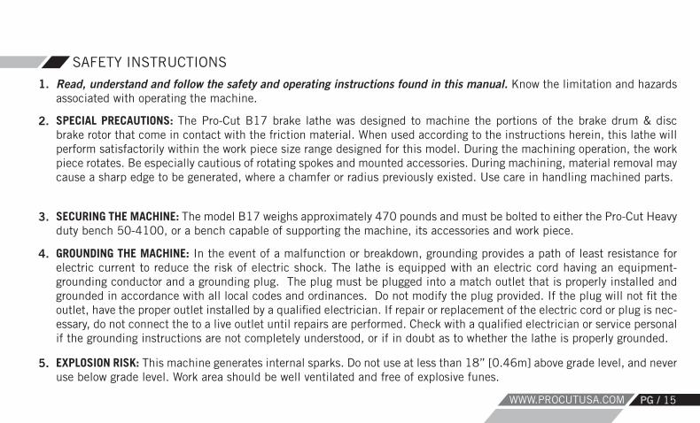
Read, understand and follow the safety and operating instructions found in this manual. Know the limitation and hazards associated with operating the machine.
SAFETY INSTRUCTIONS
1.
SPECIAL PRECAUTIONS: The Pro-Cut B17 brake lathe was designed to machine the portions of the brake drum & disc brake rotor that come in contact with the friction material. When used according to the instructions herein, this lathe will perform satisfactorily within the work piece size range designed for this model. During the machining operation, the work piece rotates. Be especially cautious of rotating spokes and mounted accessories. During machining, material removal may cause a sharp edge to be generated, where a chamfer or radius previously existed. Use care in handling machined parts.
SECURING THE MACHINE: The model B17 weighs approximately 470 pounds and must be bolted to either the Pro-Cut Heavy duty bench 50-4100, or a bench capable of supporting the machine, its accessories and work piece.
GROUNDING THE MACHINE: In the event of a malfunction or breakdown, grounding provides a path of least resistance for electric current to reduce the risk of electric shock. The lathe is equipped with an electric cord having an equipment-grounding conductor and a grounding plug. The plug must be plugged into a match outlet that is properly installed and grounded in accordance with all local codes and ordinances. Do not modify the plug provided. If the plug will not fit the outlet, have the proper outlet installed by a qualified electrician. If repair or replacement of the electric cord or plug is nec-essary, do not connect the to a live outlet until repairs are performed. Check with a qualified electrician or service personal if the grounding instructions are not completely understood, or if in doubt as to whether the lathe is properly grounded.
EXPLOSION RISK: This machine generates internal sparks. Do not use at less than 18” [0.46m] above grade level, and never use below grade level. Work area should be well ventilated and free of explosive funes.
2.
3.
4.
5.

PG / 16 800.543.6618
USE PROPER EXTENSION CORD: Use only 3-wire extension cords that have 3-prong grounding plugs and 3-pole recep-tacles that accept the lathe’s plug. Repair or replace damaged or worn cord immediately. Make sure your extension cord is in good condition. When using an extension cord, be sure to use one that is 15’ or less and 14ga or heavier (i.e. 12ga). An undersized cord will cause a drop in line voltage resulting in a loss of power and overheating. EYE SAFETY: Wear an approved safety face shield, goggles, or safety glasses. (Ordinary eyeglasses are not safety glasses and do not provide the degree of protection necessary.)
RESPIRATORY SAFETY: If the operation or area is dusty a face or dust mask should be used. PERSONAL PROTECTION: Before operating the machine, remove tie, rings,watches and other jewelry, and roll up sleeves above the elbow. Remove all outer loose clothing and confine long hair. Protective type footwear must be worn. Hearing protectors must be used where noise exceeds the level of exposure allowed in Section 1910.95 of the OSHA Regula-tions. DO NOT WEAR GLOVES.
DO NOT USE LATHE IN DANGEROUS ENVIRONMENT: Don’t use the lathe in damp or wet locations, or expose the lathe to rain. Keep the work area well lighted. WORK AREA: Keep the floor around the machine clean and free of foreign materials. Pro-Cut recommends the use of anti-skid floor strips where the operator normally stands, and that each machine has its own work area marked off. Make certain that the work area is well lighted and ventilated. Provide for adequate workspace around the machine. The work area should not be readily accessible to anyone except the operator.
SAFETY INSTRUCTIONS (continued)
6.
7.
8.
9.
10.
11.

WWW.PROCUTUSA.COM PG / 17
DO NOT OVERREACH: Maintain a balanced stance and keep your body under control at all times.
HAND SAFETY: Keep hands away from moving parts when the machine is under power. Never clear chips or debris when the machine is under power and never use your hands to clear the chips. Never use compressed air to clean machine; use only a soft bristle brush or vacuum cleaner. MACHINING PREPARATION: Tighten all appropriate locks before operating the lathe. Be sure work piece is secured. Remove adjusting keys and wrenches. Be sure to check to see that all adjusting wrenches are removed from the lathe before turning the machine on. CHECK DAMAGED PARTS: Before further use of the lathe, a guard or other part that is damaged should be carefully checked to determine if it will operate properly and perform its intended function. Check for alignment of moving parts, binding of moving parts, breakage of parts, mounting, & any other conditions that may affect the lathe’s operation. A guard or other part that is damaged should be properly repaired or replaced. MAINTAIN TOOLS WITH CARE: Keep tools sharp and clean for best and safest performance. Follow instructions for lubri-cating and changing accessories.
NEVER STAND ON LATHE: Serious injury could occur if the lathe is tipped or if the cutting tool is unintentionally con-tacted.
SAFETY INSTRUCTIONS (continued)
12.
13.
14.
15.
16.
17.

PG / 18 800.543.6618
MACHINE CAPACITY: Do not attempt to use the machine for other than passenger car and light truck drums, discs, or for operations for which the machine was not intended. CARELESS ACTS: Give the work you are doing your undivided attention! Disconnect Electrical Power before performing any service, maintenance, or changing of accessories, adapters, or work pieces on machine. JOB COMPLETION: If the operator leaves the machine area for any reason,the machine should be turned off, and the spindle brought to a complete stop before the operator departs. In addition if the operation is complete, the operator should clean the machine and work area. NEVER CLEAN THE MACHINE WITH THE POWER ON. REPLACEMENT PARTS: Use only Pro-Cut replacement parts and accessories, risk of injury may result in accessories other than those recommended are used. MISUSE: Do not use the machine for other than its intended use. If used for other purposes, Pro-Cut International, LLC, disclaims any expressed or implied warranty, and holds itself harmless for any injury or loss that may result.
SAFETY INSTRUCTIONS
18.
19.
20.
21.
22.
23.
WWW.PROCUTUSA.COM PG / 19
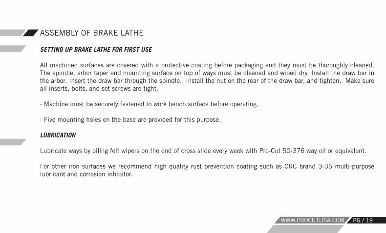
SETTING UP BRAKE LATHE FOR FIRST USE
All machined surfaces are covered with a protective coating before packaging and they must be thoroughly cleaned. The spindle, arbor taper and mounting surface on top of ways must be cleaned and wiped dry. Install the draw bar in the arbor. Insert the draw bar through the spindle. Install the nut on the rear of the draw bar, and tighten. Make sure all inserts, bolts, and set screws are tight.
· Machine must be securely fastened to work bench surface before operating.
· Five mounting holes on the base are provided for this purpose. LUBRICATION
Lubricate ways by oiling felt wipers on the end of cross slide every week with Pro-Cut 50-376 way oil or equivalent. For other iron surfaces we recommend high quality rust prevention coating such as CRC brand 3-36 multi-purpose lubricant and corrosion inhibitor.
ASSEMBLY OF BRAKE LATHE

PG / 20 800.543.6618
The B17 Multi-Speed Lathe has three spindle speeds and variable cross feeds (0.0016-0.0039” [0.04-0.1mm] per revolution) to accommodate a wide range of machining tasks. Choose spindle speed based on the size of the work piece, slower for larger diameter parts. The feed adjustment has 11 quality settings, from the finest finish (1) to the coarsest finish (11). Finer finishes use a lower feed rate, and so take longer. The coarsest finish setting, when used with Pro-Cut inserts is designed to give a finish at or about 100 micro-inch / 2.54 micron Ra, the upper roughness limit allowed for many vehicles. The fine set-ting can achieve surface finishes as low as 45 micro-inch / 1.14 micron Ra. Insert edge quality and rotor condition and material will affect these numbers.
No guarantee can be made for inserts not purchased from Pro-Cut, as insert corner radius, relief angle, material com-position and edge preparation can have a strong effect on cutting quality, insert lift, and tendency of the work piece to vibrate. Always use Genuine Pro-Cut 50-778 inserts for best results.
B17 MULTI-SPEED BRAKE LATHE OPERATION PROCEDURES OPERATION
Disc/Drum Diameter Max Speed Max Feed Max Recommended Cut Depth per Side
Up to 12” (305mm) High 11 .010” (.254mm)
12” to 14” (305-355mm) Medium 7 .010” (.254mm)
14” to 19.5” (356-495mm) Low 4 .010” (.254mm)

WWW.PROCUTUSA.COM PG / 21
The tool support plate can be rotated 90 degrees to disc or drum cutting position. The large lever in the center locks and unlocks the support plate. When the plate is in a valid position, you will see the spindle lamp illumi-nate. The position of this plate determines which axis will feed. BASIC STEPS
SETTING UP FOR ROTOR OR DRUM CUTTING
Fit work piece to arbor and clamp in placeChoose disc or drum operation by rotating the cutter support plate to the desired locationChose spindle speed (Low, Medium, High)Choose surface quality 1 to 11 (fine to coarse)Set rough tool positions with work piece not rotatingTurn on spindleSet depth of cutTurn off spindleInstall silencer(s)Turn on spindleEngage feed
1.2.3.4.5.6.7.8.9.10.11.

PG / 22 800.543.6618
DETAILED INSTRUCTIONS
IMPORTANT: The maximum amount of metal removed from the finished work piece should never exceed the manufac-turer’s machine to/minimum specifications. It is dangerous to operate a vehicle with a drum, rotor or flywheel, which has had more material removed than is allowed. Proper operation cannot be established if these specifications have been exceeded. Pro-Cut International recommends that each work piece be checked for size before mounting on the lathe and after machining. MOUNTING HUB-LESS DRUMS OR ROTORS1. Clean and check all surfaces for flatness, especially those that will come in contact with centering cones and/or bell clamps to ensure solid mounting. 2. Cleaning and properly mounting the drum or rotor prior to machining will ensure a minimum of stock removal, better surface finish and optimum braking efficiency. 3. Excessive run out or wobble of the drum or rotor after it has been properly cleaned and mounted on the arbor may indicate severe damage to the drum or rotor. These drums or rotors should not be used for further service.
INSPECTION OF BRAKE DRUMS AND ROTORS BEFORE MACHINING

WWW.PROCUTUSA.COM PG / 23
4.
5.
6. If arbor appears distorted, check for rust, burrs or chips on cones, drum or rotor, bell clamps, spacers, arbor or other mating surfaces.
A. Select two proper size bell clamps and slide one on the arbor.B. Slide spring on the arbor.C. Find the centering cone adapter that fits the center hole of the drum or rotor within the cone range and slide it on the arbor.D. Slide the drum or rotor on the arbor and then mount the other bell clamp.E. Add necessary spacers (double tapered radius adapters may be used as spacers), alignment washers (make sure they are installed concave to convex), and M24x2 hexagonal nut, or Pro-Cut Quick-Nut (de-pending on spindle) and tighten securely. Do not jerk or over tighten. When using Pro-Cut Quick-Nut, washer stack is not necessary as it has an internal convex/concave washer set.
DETAILED INSTRUCTIONS (Continued)
A. WRAP RUBBER SILENCER BAND AROUND DRUM, STARTING WITH THE PLAIN END AND MAINTAIN TENSION UNTIL THE CLIP IS SECURED. DO NOT ATTEMPT TO MACHINE DRUMS WITHOUT USING THE SILENCER BAND. Silencer should be nearest open side of drum. B. Pro-Cut 50-703 or 50-744 silencer/chip deflector should be used for rotor machining.

PG / 24 800.543.6618
1. Select the double tapered radius adapter that properly fits the inside of the large bearing race. It should sit in the race similar to a bearing and move side to side in all directions easily. If it binds in any direction, this is an indication of an incorrect adapter selection or a damaged bearing race. Correct problem before proceeding. 2. Slide the double tapered radius adapter all the way onto the arbor. If the drum or rotor contacts the lathe, a spacer may be required between the double tapered adapter and lathe. 3. Using the same procedure as in Step 1, select the double tapered radius adapter for the outside race. 4. Install the drum or rotor and position it on the back double tapered radius adapter and then slide the front double tapered radius adapter on the arbor and into the front race. 5. Use adapters or spacers as necessary to space out to the end of the arbor (See example on Pages 34-35). Double tapered radius adapters may be used as spacers. Add alignment washers (make sure they are concave to convex) and hex nut or Pro-Cut speed nut, then tighten. Do not shock load, jerk or over tighten.
6. WRAP RUBBER SILENCER BAND AROUND DRUM, STARTING WITH THE PLAIN END AND MAINTAIN TENSION UNTIL THE CLIP IS SECURED. DO NOT ATTEMPT TO MACHINE DRUMS WITHOUT USING THE SILENCER BAND. Silencer should be nearest open side of drum. Pro-Cut disc silencers should also be used for rotor machining.
MOUNTING HUBBED DRUMS OR ROTORS

WWW.PROCUTUSA.COM PG / 25
7. If arbor appears distorted, check for dirty or damaged mounting surfaces and/or adapters. Loosen and re-tighten arbor nut as described above in Step 5.
MOUNTING HUBBED DRUMS OR ROTORS (Continued)
MACHINING HUB-LESS AND HUBBED DRUMS1. Position the boring bar so that the 45-degree angle tool bit slot is toward the drum, with the cap screw to the top. BORING BAR EXTENSION SHOULD BE KEPT TO A MINIMUM. 2. For extra small diameter drums, set the boring bar at an angle towards the arbor while extending the boring bar outward from the boring bar holder. 3. Turn on the left spindle speed. Slowly advance the boring bar in the drum and contact the point of the great-est wear. 4. Note the reading on the calibrated hand wheel; back out one full turn and move to the rear of the drum. 5. Set hand wheel to .005” deeper than the noted reading; this should ensure a finished drum in one cut. 6. Select feed speed between 5-8 and engage feed.

*First side shows the Pro-Cut Brand Icon.
PG / 26 800.543.6618
1. The rotor cutting assembly must be positioned in proper alignment with the rotor. Center the disc rotor between the two tool arms. The tool arms are fed by calibrated knobs at either side of the cutting head. 2. With spindle running, set the tools for depth of cut by loosening the locking lever on top of the cutting head so that the tool arms will move freely when the calibrated knobs are turned. 3. Adjust tool arms to remove the minimum amount required to finish the rotor in one cut. DO NOT MACHINE A ROTOR TO LESS THAN MANUFACTURER’S SPECIFICATIONS. 4. If surface is scored, locate the deepest score and turn the depth knob until the tool bit bottoms out at the deepest point of the score; counting lines on the knob, back out the tool bit. Repeat on other side. If no score exists, touch rotor with tool bits near outer edge and advance calibrated tool depth knobs until full circle is scratched on. Back out the tool bit 5 lines.
5. Advance the cutting head by hand wheel until the tool bits have cleared the inner edge of the friction face. Ad-vance the micrometer knobs the number of lines you backed off in previous step. Advance both knobs 5 more lines (.005” per side) for standard cutting depth. This will usually be enough to finish the rotor in one cut. Tighten cutting head lock levers and install silencer/deflector.
MACHINING HUBLESS AND HUBBED ROTORS
6. Replacement carbide inserts have three cutting surfaces. When sufficient wear causes an in-ferior finish, rotate the carbide insert. Always begin on the single dot corner and rotate clockwise to 2 dots, then 3 dots. On *premium plus cutting tips the first corner is the brand icon.
DO NOT TURN THESE INSERTS OVER.

WWW.PROCUTUSA.COM PG / 27
MACHINING MODE FROM HOME SCREEN
EMERGENCY STOP
Spindle MotorON/OFF
Spindle Speed Control:Low-Medium-High
Feed ON/OFF
Feed Speed Control: 1 (slow/fine) thru 11 (fast/course)

PG / 28 800.543.6618
SET-UP MODE SPINDLE MOTOR MUST BE OFF
Either control knob will function in the same mode.
Set-up Mode:· Long Press > 3 seconds to enter set-up mode.· Rotate to scroll through options and toggle between choices within an option.· Short press to select option or drill down to another level.· Long press to accept changes
Available Options: · Maintenance Alert Reset· Maintenance Alerts -> On/Off· Maintenance Alert Interval -> 10-800 Power Cycles (spindle motor on for > 3 seconds)· Unit of measure -> mm/inches (for machines with optional measuring cutting head)

WWW.PROCUTUSA.COM PG / 29
STATISTICS MODE SPINDLE MOTOR MUST BE OFF
Either control knob will function in the same mode.
Set-up Mode:· Short Press < 3 seconds to enter Statistics mode.· Rotate to scroll through options and toggle between choices between an option.· Short press to select option or drill down to another level.
Available Statistics: · Spindle motor run time (represented in hours and tenths of an hour)· Power Cycles (how many times the spindle motor has been turned on for > 3 seconds)· Disc hours (actual cut time of discs) represented in hours and tenths of an hour · No. of discs machined (based on 1 pass)· Drum hours (actual cut time of drums) represented in hours and tenths of an hour· No. of drums machined (based on 1 pass)· Module program version numbers (several)

PG / 30 800.543.6618
ADVANCED TIPSIf machining very large work pieces, you can use the supplied manual slide locks to lock the slide which is not in active use. For example if you are cutting a rotor you could lock the drum slide (and vice-versa). If you are taking moderate cut depths or working with medium or small work pieces this step is likely not necessary. Just remember to unlock the lever before you dismount the work piece as a favor to your future self.
Sharp tools are vital to satisfactory operation.When ordering supplies or replacement parts for this machine, always give the model # and serial # of the machine. Use only Genuine Pro-Cut parts.

Arbor
Bell Clamp
SpringConeDrum
Bell Clamp
Spacer
*Spherical Washer Set
Nut
*SphericalWasher SetAlignment
WWW.PROCUTUSA.COM PG / 31
DRUM INSTALLATION / Recommended Assembly

Arbor
Bell Clamp
SpringCone
Disc/Rotor
Bell Clamp
Spacer
*Spherical Washer Set
Nut
*SphericalWasher Set
DISC INSTALLATION / Recommended Assembly
PG / 32 800.543.6618

1
8
30
21
9
32
2
14
20
25
34
35
2719
32
2328
317
295
26
1615
36
22
13
12
11
186
24
CABLES(NOT SHOWN)
4
3
50-4000
17
10 10
ITEM NO. PART NUMBER
Mk 1.3/QTY.
1 50-4276 12 50-4092 13 36-4006 14 50-4009 15 50-4059 16 37-4031 17 50-4277 18 50-4054 19 50-4275 1
10 50-4345 211 50-4192 112 50-4099 113 50-4096 114 50-4063 115 50-1330 116 50-4279 117 50-4331 118 50-4079 419 50-4170 120 37-4046 121 50-4274 122 50-4142 123 50-4190 124 35-4004 425 37-4063 326 35-278 327 35-339 428 35-4006 129 30-204 130 35-4002 431 35-4003 332 35-4027 433 35-4030 434 35-4031 335 35-4058 436 37-4047.1 1
PART NUMBER DESCRIPTION QTY.50-4207 Spindle motor power cable 150-4208 Rotary sensor cable 150-4212 AC Power Cord NEMA 5-15 150-4213 Connect 50-2154,50-2155 and 50-2158. 150-4214 Feed motor and Clutch cable 150-4218 Gooseneck LED power cable(Outside the E-box) 150-4220 Dedicated ground cable 1
33
WWW.PROCUTUSA.COM PG / 33

11 12
54
32
1
87
15
13
10
9
6
14
50-4009ITEM NO. PART NUMBER QTY.
1 50-4010 12 50-4011 23 50-4012 14 50-4013 15 50-4014 16 50-4015 17 50-4016 18 50-4017 19 50-4035 1
10 50-4018 111 50-4019 112 50-4020 113 50-4021 114 50-4022 215 50-4023 2
PG / 34 800.543.6618

11
12
10
17
67
154
9
5
1
3
8 16
14
13
2
18
50-133019
ITEM NO.
PART NUMBER QTY.
1 50-1331 1
2 37-1333 2
3 50-1332 1
4 50-1333 1
5 50-1334 1
6 50-1335 1
7 50-1336 1
8 50-1339 2
9 50-053 1
10 50-252 1
11 37-1331 1
12 50-1343 1
13 35-1331 2
14 35-1335 2
15 37-1332 2
16 35-1332 2
17 35-1330 2
18 37-1330 2
19 37-1306 1
WWW.PROCUTUSA.COM PG / 35

19
15
4
2
5
5
6
17
137
91081211
2014
13
18
16
23
50-4044
21
24
22
ITEM NO. PART NUMBER feed box/QTY.
1 50-4048 12 37-4022 13 35-4008 44 50-4049 15 35-4019 26 37-4018 17 37-4016 18 35-4001 39 50-4047 110 37-4015 111 37-4014 112 50-4050 113 50-4078 114 50-4046 115 37-4020 116 37-4019 117 35-341 118 35-919 619 50-4027 120 50-4045 1
21 37-4060 122 37-4051 223 35-4004 224 37-4074 125 50-4301.1 126 50-4302 127 35-955 4
PG / 36 800.543.6618

10
4
31
2
11
13
8
5
6
12
9
7
50-4063
ITEM NO. PART NUMBER QTY.
1 50-4064 12 35-4011 23 37-4026 24 35-4022 25 35-4021 46 50-4006 17 37-4032 28 37-4001 19 35-4000 210 50-4007 111 50-4061 112 37-4033 113 50-4180 114 37-4051 3
WWW.PROCUTUSA.COM PG / 37
27
21
4
2
5
5
6
25
137
17
8
19
18
16
20
26
23
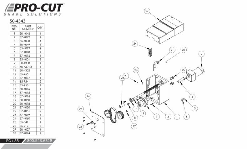
50-4343
24
28
22
ITEM NO.
PART NUMBER QTY.
1 50-4048 12 37-4022 13 35-4008 44 50-4049 15 35-4019 26 37-4018 17 37-4016 18 35-4001 39 50-4300 1
10 50-4301.1 111 50-4302 112 35-955 413 37-4077 114 35-954 215 35-953 116 50-4045 117 37-4015 118 37-4014 119 50-4050 120 50-4078 121 37-4020 122 37-4051 223 37-4019 124 37-4060 125 35-341 126 35-919 627 50-4027 128 37-4074 1
PG / 38 800.543.6618

3
5
4
10
1113
12
15
14
16
12
19
20
21
31 9
12
17
1
6
12
32
30
7
2
27 23
28
29
18
8
12
24
2526
22
50-4345BOM Table
ITEM NO. PART NUMBER 50-4345/QTY.
1 50-4350 12 50-4355 13 50-4027 14 37-4022 15 50-4049 16 50-4351 17 50-4354 18 50-4352 19 50-4353 1
10 37-4018 111 37-4016 112 35-335 1313 37-4015 114 37-4014 115 50-4050 116 50-4078 117 37-4020 118 37-4051 219 37-4019 120 37-4060 121 37-4052 422 37-4074 123 50-4300 124 50-4301.1 125 50-4302 126 35-955 427 37-4077 128 35-954 229 35-953 130 35-4048 131 35-341 232 35-342 4
WWW.PROCUTUSA.COM PG / 39

Cables(Not Shown)
50-4331
ITEM NO.
PART NUMBER QTY.
1 50-4072 1
2 35-339 8
3 50-2154 1
4 50-2157_F 1
5 50-2159 1
6 37-4050 2
7 37-4034 1
8 50-2215 1
9 35-4033 14
10 50-4194 2
11 50-4326 1
12 3M 4516 3_8 inch 2
13 3M 4516 3_8 inch 2
14 50-4327 1
15 50-2564 1
16 Air Block Foam 1
17 Air Block Foam 2
18 Air Block Foam 1
ITEM NO. PART NUMBER DESCRIPTION QTY.
1 50-4200 Gooseneck LED power cable(Inside the E-box) 1
2 50-4205 20pin IDC cable 1
3 50-4206 24V power input 1
4 50-4209 50-2159 power cable 1
5 50-4210 10pin IDC cable 1
6 50-4211 50-2159 outputs to DB15 1
3 4 5
7
10
8
1
6
9
112
9
13
12
1514
17
18
16 17
PG / 40 800.543.6618

2
3
1
50-4096
BOM Table
ITEM NO. PART NUMBER QTY.
1 50-4097 1
2 50-4098 1
3 35-4032 1
3
2
1
50-4192ITEM NO. PART NUMBER QTY.
1 50-4193 1
2 35-4032 1
3 50-4098 1
WWW.PROCUTUSA.COM PG / 41
12 11
7
13
9
8
6
3
2
1
1045
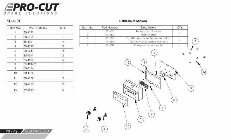
Cables(Not shown)
ITEM NO. PART NUMBER QTY.
1 50-4171 1
2 50-2155 1
3 35-801 4
4 50-2145 2
5 50-2241 2
6 35-4041 2
7 35-4033 6
8 37-4047.2 1
9 50-4174 1
10 50-4176 1
11 50-4178 2
12 50-4179 2
13 37-4063 4
item No. Part Number Describtion QTY.1 50-4201 Rotary control cable 12 50-4204 10pin to DB15 13 50-4221 Spindle start/stop button and cable 14 50-4222 Feed start/stop button and cable 15 50-4217 E-stop button and cable 1
50-4170
PG / 42 800.543.6618

13 11 1012
5
4
6
7982
3
1
50-4274ITEM NO.
PART NUMBER QTY.
1 50-4051 1
2 50-4052 1
3 50-4053 1
4 35-4005 4
5 36-4003 4
6 37-4061 1
7 37-4028 1
8 50-4032 2
9 35-4056 4
10 35-4001 7
11 50-4026 1
12 50-4043 1
13 35-4028 1
WWW.PROCUTUSA.COM PG / 43

5
3
4
627
8
9
1
11
13
12
10
50-4275ITEM NO.
PART NUMBER QTY.
1 50-4055 1
2 50-4032 2
3 35-4056 4
4 50-4053 1
5 35-4028 1
6 50-4052 1
7 37-4061 1
8 36-4003 4
9 35-4005 4
10 37-4028 1
11 50-4026 1
12 35-4001 5
13 50-4043 1
PG / 44 800.543.6618

15
14
13
11
1210
2
4
18
1
17
5
73
6
9
820
16
19
50-4276ITEM NO.
PART NUMBER QTY.
1 37-4009 12 50-4057 13 37-4007 14 37-4003 15 37-4004 16 50-4056 17 37-4010 18 37-4005 19 37-4006 1
10 37-4011 111 50-4058 112 37-4030 113 35-4004 314 50-4070 115 35-4001 316 50-4060 117 37-4008 118 35-4015 319 50-4137 120 50-4800 1
WWW.PROCUTUSA.COM PG / 45

8
6
4
10
7
2
1
5
3
50-4277ITEM NO. PART NUMBER QTY.
1 37-4024 12 50-4090 13 35-4006 44 37-4045 15 50-4024 16 50-4139 17 35-4026 48 36-4017 4
10 35-4057 4
PG / 46 800.543.6618

1
3
2
50-4279ITEM NO. PART NUMBER QTY.
1 50-4005 1
2 50-4008 1
3 35-4020 2
WWW.PROCUTUSA.COM PG / 47

PG / 48 800.543.6618
SYSTEM ERROR MESSAGES
DISPLAY TEXTTYPE / DESCRIPTION CAUSE CORRECTIVE ACTION
Blocking / Low DC Voltage Input Volt / SagVoltage measured from AC/DC power supply is below 20V. This can occur if the load exceeds the motor capability, or the motor cannot start.
Ensure adequate AC supply voltage.Decrease cut feed rate.Power cycle lathe.
Blocking / Emergency Stop Active E.STOP / SAFTYE-Stop button is down. On lathes equipped with protective screens, this message will also appear if the lower door is not fully closed.
Release e-stop button by rotating switch cap.IF dust encloser w/safety switches is installed, ensure side door is fully closed.
Long duration heavy cutting loads can cause this, as can excessively high ambient tempera-tures.
None – This fault condition will stop the spin-dle/feed motors and and prevent lathe opera-tion until the internal temperature decreases.
Blocking / High Temperature Fault TEMP / FAULT / HIGH
OVER / AMP / LIMIT
Feed / temp
Blocking / Excessive Current Draw
Blocking / Feed PCB Temp. Fault
Very high motor load typically caused by ex-cess material removal rate.
This is a “latching” fault condition. On initial detection the spindle/feed motors are stopped. Once the motors are stopped, the over-current condition goes away but the error message is “latched” on (ie does not clear automatically). To resume lathe operation the user should press the start/stop button and wait for the normal status message display to re-appear. To restart the spindle motor, press the start/stop button again.
Feed motor is over temperature limit. Reduce cutting depth or feed rate. Check that cutting inserts are not damaged or dull.
WWW.PROCUTUSA.COM PG / 49
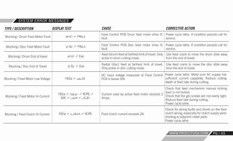
drum / faultBlocking / Drum Feed Motor Fault
SYSTEM ERROR MESSAGES
DISPLAY TEXTTYPE / DESCRIPTION CAUSE CORRECTIVE ACTIONFeed Control PCB Drum feed motor drive IC fault.
Power cycle lathe. If condition persists call for service.
Blocking / Disc Feed Motor Fault disc / fault Feed Control PCB Disc feed motor drive IC fault.
Power cycle lathe. If condition persists call for service.
Axial (drum) feed at farthest limit of travel. Only active in drum cutting mode.
Use feed crank to move the drum slide away from the end of travel.Blocking / Drum End of travel drum / eot
disc / eotBlocking / Disc End of TravelRadial (disc) feed at farthest limit of travel. Only active in disc cutting mode.
Use feed crank to move the disc slide away from the end of travel.
Blocking / Feed Motor Low Voltage feed / voltsDC Input voltage measured at Feed Control PCB is below 20V.
Power cycle lathe. Make sure AC supply has sufficient current capability. Reduce cutting depth or feed rate during cutting.
Blocking / Feed Motor Hi Currentfeed / motor / amps /see / lock / lever
Current used by active feed motor exceeds 2 Amps.
Check that feed mechanism manual locking lever is not locked. Check that the gib screws are not overly tight. Reduce feed rate during cutting.Power cycle lathe.
Blocking / Feed Clutch Hi Current feed / clutch / amps Feed clutch current exceeds 2A.
Check for wiring faults and shorts on the feed clutch wiring, especially for clutch supply wires shorting to adjacent metal parts.Power cycle lathe.

PG / 50 800.543.6618
SYSTEM ERROR MESSAGES
DISPLAY TEXTTYPE / DESCRIPTION CAUSE CORRECTIVE ACTION
Blocking / Spindle Motor HighCurrent During Start
rotor / lockSpindle motor draws excessive current during startup.Spindle motor stops automatically.
Check cutting tool is not touching drum/disc (common if you stop mid-cut & do not move in-serts back out by adjusting depth/feed crank). Press start/stop button for spindle restart.
Exception / Service Alert (SA) Message
maint / due / call /800- / 543- / 6618
This message is added to the sequential mes-sage display rotation when service alerts are enabled and the sum of disc cuts plus drum cuts exceeds the programmed service alert in-terval (default 400).
The service alert can be cleared via the Setup Menu Main->Alert->Reset command. Dis-abling service alerts or setting the SAInterval to a larger value will also clear the SA condition. This will re-occur each time the service alert counter is reached. It does not prevent use of the lathe.
This message is present in the normal sequen-tial message display.Note: the leading character is the top bar of the 1st character.
None – Message is normally active. Rotate left dial to adjust spindle RPM Low (100 RPM), Med(ium) (140 RPM), High (180 RPM).Exception / Feed Speed Setting -high
-11
-1.234
Exception / Spindle Speed Setting
Exception / Cutting Tips Distance
This message is present in the normal sequen-tial message display.Note: the leading character is the middle bar of the 1st character.
None – Message is normally active. Rotate right dial to adjust feed rate from 1 (slowest) to 11 (fastest). Why 11? Because sometimes you just need to give it 110%.
This message is present in the normal sequen-tial message display rotation provided that the lathe is equipped with a thickness measure-ment electronics (optional). Note: the leading character is the lower bar of the 1st character.
None - Message is displayed if electronic mea-surement option is installed. If inch units are selected in the setup menu, the thickness will be displayed as: 1.234; if mm units selected it will display as: 56.78 (note pos. of dec. pt.).

WWW.PROCUTUSA.COM PG / 51
SYSTEM ERROR MESSAGES
DISPLAY TEXTTYPE / DESCRIPTION CAUSE CORRECTIVE ACTION
Exception / Tcm Low/NoBattery Alert
TCM / lobatFor lathes equipped with a batter-backed disc thickness measuring system, battery is low.
Plug in lathe and leave plugged in to charge this battery. Battery alert will clear automati-cally when battery has sufficient charge.Press start/stop button to attempt spindle restart.
Exception / Head Calibration Alert head / cal
Lathe is equipped with a disc measurement system but any previously set calibration val-ues have been lost (possible due to low Tcm battery).
Use the setup menu to perform a head calibra-tion procedure.
This is a general fault message indicating one or more of:- Tcm internal memory fault.- No microphone signal detected.- No slide sensor or rotary encoders detected.- One or both of the rotary encoders are report-ing faults.
Power cycle lathe and/or replace Tcm.
Exception / Tcm General Fault Message
tcm / fault / call /1-603 / -298- / 5200
Temp / Fault / 50 C
top / door
Exception / Temperature Fault
Exception / Upper Protective Shield Warning
Previously a temperature fault has occurred. Current temp. is below the fault threshold but still too warm to restart spindle. The message text displays current temperature in deg. C.
Wait for the displayed temperature to decrease below 50C, press start/stop button to clear the latched temperature fault. Press start/stop again to restart spindle.
Some dust enclosures are equipped with safe-ty switches that monitor the doors around the cutting tool area. This message indicates that the upper door is not in a safe position. Note: This is a status warning only and does not pre-vent operation of the spindle.
Check to ensure that the upper safety barrier is fully closed.
26

PG / 52 800.543.6618
SYSTEM ERROR MESSAGES
DISPLAY TEXTTYPE / DESCRIPTION CAUSE CORRECTIVE ACTION
Exception / Side Protective Door Warning side / door (repeats 3x)
Operator has attempted to start feed motor while side protective door is not closed.
Close side protective door then press feed start/stop button.
Exception / Spindle Power Limiting pwlmt
For lathes equipped with Rev 1 spindle power control boards, if the measured motor current exceeds 30A, the spindle power level is auto-matically reduced by about 8%. If this has oc-curred, and the operator attempts to manual increase the spindle speed during a cut, this warning is displayed and the attempted spin-dle adjustment is ignored.
Reduce cutting depth or feed rate. Check that cutting inserts are not damaged or dull.
Lathe is equipped with a disc thickness mea-suring and cutting sounds have been detected.
None. Informational alert only. Cut alert can occur when cutting disc or drum. Thickness measurement only available when cutting a disc.
Exception / Cut Detected cut
nocut
E_stop (fast flash 4x)
Exception / Not Cuttin
Exception / Spindle Start Ignored
Lathe is equipped with a disc thickness mea-suring and cutting sounds have ceased.
None. Informational alert only. Cut alert can occur when cutting disc or drum.
E-Stop button is locked in the down/active po-sition and user has pressed the spindle or feed start/stop button.
None - clears automatically.Release e-stop button by rotating switch cap.

WWW.PROCUTUSA.COM PG / 53
NOTES

PG / 54 800.543.6618
MAINTENANCE SCHEDULE
DATE DRO READINGS| HOURS | TOTAL DISCS | TOTAL DRUMS |MONTH / DAY / YEAR |
NOTES

WWW.PROCUTUSA.COM PG / 55
MAINTENANCE SCHEDULE
DATE DRO READINGS| HOURS | TOTAL DISCS | TOTAL DRUMS |MONTH / DAY / YEAR |
NOTES

© PRO-CUT INTERNATIONAL, LLC
Pro-Cut International, LLC10 Technology Drive #4West Lebanon, NH 03784
Global inquiries please see:
www.procutusa.com
P. 800.543.6618 / 603.298.5200F. 603.298.8404E. [email protected]
50-4149PRINTED WITH PRIDE IN THE U.S.A.
R2/2021