Embed Size (px)
Citation preview
TECHNICAL MANUAL OPERATOR AND FIELD MAINTENANCE MANUAL
FOR
SPECIAL PURPOSE INFRARED (SPIR) ILLUMINATOR
WITH LED ILLUMINATOR (850nm)
SPIR � P/N 60480 ____600mW IR LED Illuminator w/ mount and remote cable � P/N 60480A ____600mW IR LED Illuminator w/ mount and remote cable � P/N 60481 ____600mW IR LED Illuminator � P/N 60481A ____600mW IR LED Illuminator
70 Garden Court • Monterey, CA 93940 U.S.A.
Tel 831-373-0701/800-235-2162 (outside CA) • Fax 831-373-0903 [email protected] • www.laserdevices.com

b
c
SAFETY SUMMARY
This safety summary contains general safety warnings and hazardous materials warnings that must be understood and applied during operation and maintenance of this equipment. Failure to observe these precautions could result in serious injury or death to personnel. Also included are explanations of safety and hazardous materials icons used within this technical manual. The Special Purpose Infrared (SPIR) illuminator is an eye-safe light emitting diode (LED) illuminator.
EXPLANATION OF SAFETY WARNINGS ICONS
ACCIDENTAL DISCHARGE – hazard symbol indicates extreme danger for personnel from weapons fire. EXPLOSION – hazard symbol shows that the material may explode if obstructed. EYE INJURY - hazard symbol indicates extreme danger for eyes from light beams and reflections.
EXPLANATION OF SAFETY ALERTS WARNING – Identifies a clear danger to the person performing
procedure. CAUTION – Identifies risk of damage to the equipment. NOTE – Identifies essential procedures, conditions, statements, or convey important instructional data to the user.
SAFETY SUMMARY, continued
d
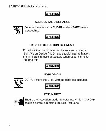
WARNING
ACCIDENTAL DISCHARGE
Be sure the weapon is CLEAR and on SAFE before proceeding.
WARNING
RISK OF DETECTION BY ENEMY
To reduce the risk of detection by an enemy using a Night Vision Device (NVD), avoid prolonged activation. The IR beam is more detectable when used in smoke, fog, and rain.
WARNING
EXPLOSION
DO NOT store the SPIR with the batteries installed.
WARNING
EYE INJURY
Ensure the Activation Mode Selector Switch is in the OFF position before inspecting the Exit Port Lens.
e
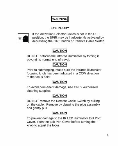
WARNING
EYE INJURY
If the Activation Selector Switch is not in the OFF position, the SPIR may be inadvertently activated by depressing the FIRE button or Remote Cable Switch.
CAUTION
DO NOT defocus the infrared illuminator by forcing it beyond its normal end of travel.
CAUTION Prior to submerging, make sure the infrared illuminator focusing knob has been adjusted in a CCW direction to the focus point.
CAUTION To avoid permanent damage, use ONLY authorized cleaning supplies.
CAUTION DO NOT remove the Remote Cable Switch by pulling on the cable. Remove by clasping the plug assembly and gently pull.
CAUTION To prevent damage to the IR LED illuminator Exit Port Cover, open the Exit Port Cover before turning the knob to adjust the focus.

i
TABLE OF CONTENTS
SAFETY SUMMARY ................................................................... c TABLE OF CONTENTS ................................................................ i LIST OF FIGURES ...................................................................... ii LIST OF TABLES ....................................................................... iii HOW TO USE THIS MANUAL .................................................... iv
1 CHAPTER I .................................................................................. 1-1 GENERAL INFORMATION ....................................................... 1-1
2 CHAPTER II ................................................................................. 2-1 EQUIPMENT DESCRIPTION ................................................... 2-1
3 CHAPTER III ................................................................................ 3-1 SECTION I OPERATING INSTRUCTIONS............................... 3-1 SECTION II MOUNTING PROCEDURES ............................... 3-10
4 CHAPTER IV ................................................................................ 4-1 SECTION I USER PREVENTIVE MAINTENANCE CHECKS ... 4-1 SECTION II TROUBLESHOOTING .......................................... 4-5 SECTION III MAINTENANCE ................................................... 4-7
5 CHAPTER V ................................................................................. 5-1 SECTION III SERVICE/PACKING AND UNPACKING .............. 5-1
A APPENDIX A................................................................................ A-1 REPAIR PARTS ...................................................................... A-1
ii
LIST OF FIGURES
Figure 2-1 SPIR Features................................................................ 2-1 Figure 2-2 Major Components ......................................................... 2-3 Figure 3-1 Battery Installation CR123A Version ............................... 3-2 Figure 3-2 Activation Mode Selector Switch .................................... 3-3 Figure 3-3 Integrated Momentary Activation Switch ......................... 3-5 Figure 3-4 Activation LED/Low Battery Indicator .............................. 3-6 Figure 3-5 Installation of the Remote Cable Switch ......................... 3-7 Figure 3-6 Exit Port Cover Installation ............................................. 3-8 Figure 3-7 The IR LED illuminator Focusing Knob ........................... 3-9 Figure 3-8 Quick Release Mount Attachment ................................ 3-10 Figure 3-9 Quick Release Mount Configuration ............................. 3-11 Figure 3-10 Top Mounted .............................................................. 3-12 Figure 4-1 Battery Removal and Installation .................................... 4-9 Figure 4-2 Remove and Replace Exit Port Cover Retaining
Straps........................................................................... 4-10 Figure A-1 Repair Parts .................................................................. A-1
iii
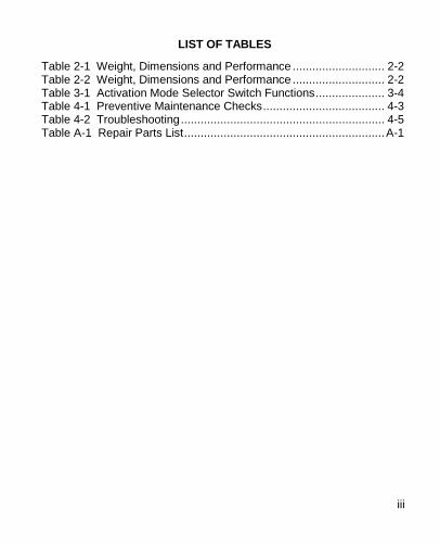
LIST OF TABLES
Table 2-1 Weight, Dimensions and Performance ............................ 2-2 Table 2-2 Weight, Dimensions and Performance ............................ 2-2 Table 3-1 Activation Mode Selector Switch Functions ..................... 3-4 Table 4-1 Preventive Maintenance Checks ..................................... 4-3 Table 4-2 Troubleshooting .............................................................. 4-5 Table A-1 Repair Parts List ............................................................. A-1
iv
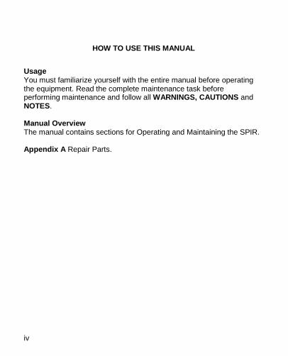
HOW TO USE THIS MANUAL
Usage You must familiarize yourself with the entire manual before operating the equipment. Read the complete maintenance task before performing maintenance and follow all WARNINGS, CAUTIONS and NOTES. Manual Overview The manual contains sections for Operating and Maintaining the SPIR. Appendix A Repair Parts.
1-1
1 CHAPTER I
GENERAL INFORMATION
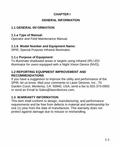
1.1 GENERAL INFORMATION
1.1.a Type of Manual: Operator and Field Maintenance Manual.
1.1.b Model Number and Equipment Name: SPIR, Special Purpose Infrared Illuminator.
1.1.c Purpose of Equipment: To illuminate shadowed areas or targets using infrared (IR) LED illuminator for users equipped with a Night Vision Device (NVD).
1.2 REPORTING EQUIPMENT IMPROVEMENT AND RECOMMENDATIONS If you have a suggestion to improve the utility and performance of the SPIR, let us know. Mail your comments to Laser Devices, Inc., 70 Garden Court, Monterey, CA 93940, USA, send a fax to 831-373-0903 or send an Email to [email protected].
1.3 WARRANTY INFORMATION This item shall conform to design, manufacturing, and performance requirements and be free from defects in material and workmanship for one (1) year from the date of manufacture. This warranty does not protect against damage due to misuse or mishandling.
GENERAL INFORMATION, continued
1-2
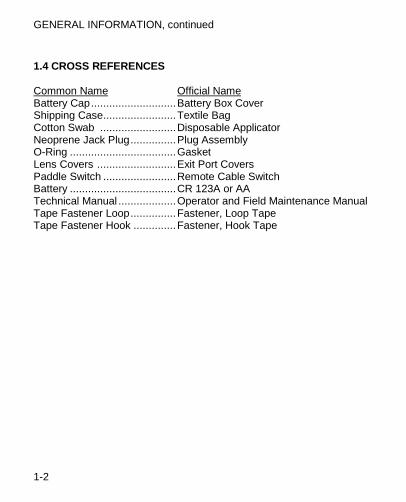
1.4 CROSS REFERENCES Common Name Official Name Battery Cap ............................ Battery Box Cover Shipping Case ........................ Textile Bag Cotton Swab ......................... Disposable Applicator Neoprene Jack Plug ............... Plug Assembly O-Ring ................................... Gasket Lens Covers .......................... Exit Port Covers Paddle Switch ........................ Remote Cable Switch Battery ................................... CR 123A or AA Technical Manual ................... Operator and Field Maintenance Manual Tape Fastener Loop ............... Fastener, Loop Tape Tape Fastener Hook .............. Fastener, Hook Tape
1-3
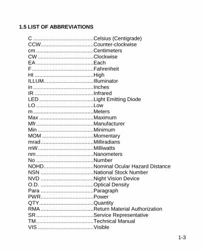
1.5 LIST OF ABBREVIATIONS
C ........................................Celsius (Centigrade) CCW...................................Counter-clockwise cm ......................................Centimeters CW .....................................Clockwise EA ......................................Each F .........................................Fahrenheit HI .......................................High ILLUM .................................Illuminator in ........................................Inches IR .......................................Infrared LED ....................................Light Emitting Diode LO ......................................Low m ........................................Meters Max ....................................Maximum Mfr ......................................Manufacturer Min .....................................Minimum MOM ..................................Momentary mrad ...................................Milliradians mW .....................................Milliwatts nm ......................................Nanometers No ......................................Number NOHD .................................Nominal Ocular Hazard Distance NSN ...................................National Stock Number NVD ...................................Night Vision Device O.D. ...................................Optical Density Para ...................................Paragraph PWR ...................................Power QTY ....................................Quantity RMA ...................................Return Material Authorization SR ......................................Service Representative TM ......................................Technical Manual VIS .....................................Visible

2-1
2 CHAPTER II
EQUIPMENT DESCRIPTION
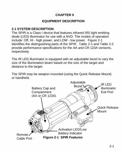
2.1 SYSTEM DESCRIPTION The SPIR is a Class I device that features infrared (IR) light emitting diode (LED) illuminator for use with a NVD. The modes of operation include: Off, HI - high power, and LOW - low power. Figure 2-1 identifies the distinguishing parts of the SPIR. Table 2-1 and Table 2-2 provide performance specifications for the AA and CR 123A versions, respectively. The IR LED illuminator is equipped with an adjustable bezel to vary the size of the illumination beam based on the size of the target and distance to the target. The SPIR may be weapon mounted (using the Quick Release Mount) or handheld.
Figure 2-1 SPIR Features
Battery Cap and Compartment (AA or CR 123A)
IR LED illuminator Exit Port
Quick Release Mount
Remote Cable Port
Activation LED/Low Battery Indicator
Adjustable Bezel
EQUIPMENT DESCRIPTION, continued
2-2
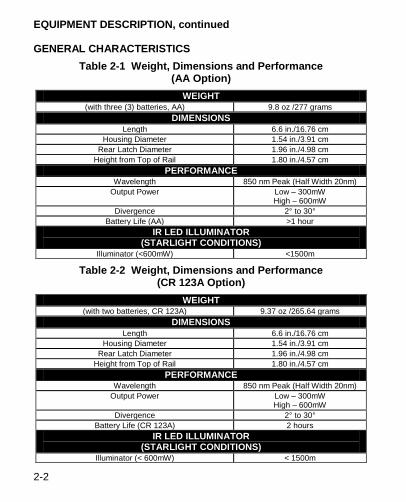
GENERAL CHARACTERISTICS Table 2-1 Weight, Dimensions and Performance
(AA Option) WEIGHT
(with three (3) batteries, AA) 9.8 oz /277 grams DIMENSIONS
Length 6.6 in./16.76 cm Housing Diameter 1.54 in./3.91 cm
Rear Latch Diameter 1.96 in./4.98 cm Height from Top of Rail 1.80 in./4.57 cm
PERFORMANCE Wavelength 850 nm Peak (Half Width 20nm)
Output Power Low – 300mW High – 600mW
Divergence 2° to 30° Battery Life (AA) >1 hour
IR LED ILLUMINATOR (STARLIGHT CONDITIONS)
Illuminator (<600mW) <1500m
Table 2-2 Weight, Dimensions and Performance (CR 123A Option)
WEIGHT (with two batteries, CR 123A) 9.37 oz /265.64 grams
DIMENSIONS Length 6.6 in./16.76 cm
Housing Diameter 1.54 in./3.91 cm Rear Latch Diameter 1.96 in./4.98 cm
Height from Top of Rail 1.80 in./4.57 cm PERFORMANCE
Wavelength 850 nm Peak (Half Width 20nm) Output Power Low – 300mW
High – 600mW Divergence 2° to 30°
Battery Life (CR 123A) 2 hours IR LED ILLUMINATOR
(STARLIGHT CONDITIONS) Illuminator (< 600mW) < 1500m
2-3
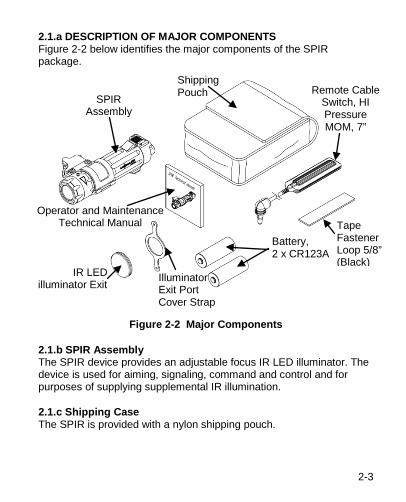
2.1.a DESCRIPTION OF MAJOR COMPONENTS Figure 2-2 below identifies the major components of the SPIR package.
Figure 2-2 Major Components
2.1.b SPIR Assembly The SPIR device provides an adjustable focus IR LED illuminator. The device is used for aiming, signaling, command and control and for purposes of supplying supplemental IR illumination.
2.1.c Shipping Case The SPIR is provided with a nylon shipping pouch.
Shipping Pouch Remote Cable
Switch, HI Pressure MOM, 7”
Operator and Maintenance Technical Manual
Illuminator Exit Port Cover Strap
IR LED illuminator Exit
SPIR Assembly
Tape Fastener Loop 5/8” (Black)
Battery, 2 x CR123A
EQUIPMENT DESCRIPTION, continued
2-4
2.1.d Remote Cable Switch A seven (7) inch, right angle, Remote Cable Switch activates the SPIR in a momentary (MOM) mode by depressing the pressure pad once. Pressing the pressure pad twice in rapid succession will activate the device continuously for five (5) minutes. Pressing the pressure pad again will return the device to momentary activation. The pressure pad provides a tactile (silent) click that indicates when the switch has been activated.
2.1.e Tape Fastener Loop The Tape Fastener Loop is provided to secure the Remote Cable Switch to the weapon in a position convenient to the user. The Tape Fastener Hook is pre-attached by the manufacturer to the pressure pad switch and is used to secure the Remote Cable Switch to the weapon in a position convenient to the user.
2.1.f Battery Three (3) AA or two (2) CR 123A (model dependent) batteries are used as a power supply for operating the SPIR. The use of high-quality batteries is recommended to achieve maximum runtime.
2.1.g Operator and Field Maintenance Manual The Operator and Field Maintenance Manual provide safety information, equipment information, operating instructions, mounting procedures, and maintenance procedures.
NOTE
You must read the entire Operator and Field Maintenance Manual before operating the SPIR and follow all WARNINGS, CAUTIONS and NOTES.
2.1.h Illuminator Exit Port Cover and Strap The Exit Port Cover strap attaches the Exit Port cover to the SPIR assembly to prevent IR energy emission and protects the lens.
3-1
3 CHAPTER III
SECTION I OPERATING INSTRUCTIONS
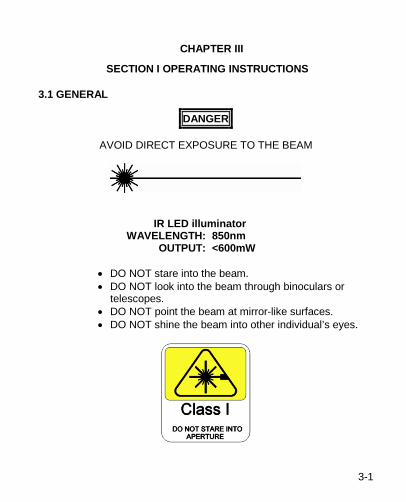
3.1 GENERAL
DANGER
AVOID DIRECT EXPOSURE TO THE BEAM
IR LED illuminator WAVELENGTH: 850nm OUTPUT: <600mW
• DO NOT stare into the beam. • DO NOT look into the beam through binoculars or
telescopes. • DO NOT point the beam at mirror-like surfaces. • DO NOT shine the beam into other individual’s eyes.
CHAPTER III, continued OPERATING INSTRUCTIONS, continued
3-2
3.2 SPIR CONTROLS AND INDICATORS This section contains a description of the controls and adjustments for the SPIR.
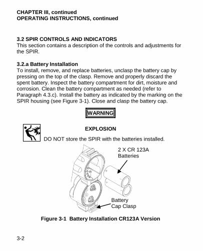
3.2.a Battery Installation To install, remove, and replace batteries, unclasp the battery cap by pressing on the top of the clasp. Remove and properly discard the spent battery. Inspect the battery compartment for dirt, moisture and corrosion. Clean the battery compartment as needed (refer to Paragraph 4.3.c). Install the battery as indicated by the marking on the SPIR housing (see Figure 3-1). Close and clasp the battery cap.
WARNING
EXPLOSION
DO NOT store the SPIR with the batteries installed.
Figure 3-1 Battery Installation CR123A Version
Battery Cap Clasp
2 X CR 123A Batteries
3-3
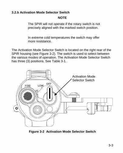
3.2.b Activation Mode Selector Switch NOTE
The SPIR will not operate if the rotary switch is not precisely aligned with the marked switch position. In extreme cold temperatures the switch may offer more resistance.
The Activation Mode Selector Switch is located on the right rear of the SPIR housing (see Figure 3-2). The switch is used to select between the various modes of operation. The Activation Mode Selector Switch has three (3) positions. See Table 3-1.
Figure 3-2 Activation Mode Selector Switch
Activation Mode Selector Switch
CHAPTER III, continued OPERATING INSTRUCTIONS, continued
3-4
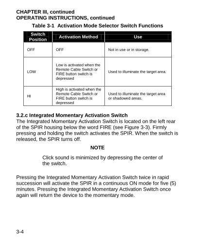
Table 3-1 Activation Mode Selector Switch Functions Switch
Position Activation Method Use
OFF OFF Not in use or in storage.
LOW
Low is activated when the Remote Cable Switch or FIRE button switch is depressed
Used to illuminate the target area.
HI
High is activated when the Remote Cable Switch or FIRE button switch is depressed
Used to illuminate the target area or shadowed areas.
3.2.c Integrated Momentary Activation Switch The Integrated Momentary Activation Switch is located on the left rear of the SPIR housing below the word FIRE (see Figure 3-3). Firmly pressing and holding the switch activates the SPIR. When the switch is released, the SPIR turns off.
NOTE
Click sound is minimized by depressing the center of the switch.
Pressing the Integrated Momentary Activation Switch twice in rapid succession will activate the SPIR in a continuous ON mode for five (5) minutes. Pressing the Integrated Momentary Activation Switch once again will return the device to the momentary mode.
3-5
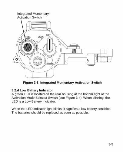
Figure 3-3 Integrated Momentary Activation Switch
3.2.d Low Battery Indicator A green LED is located on the rear housing at the bottom right of the Activation Mode Selector Switch (see Figure 3-4). When blinking, the LED is a Low Battery Indicator. When the LED indicator light blinks, it signifies a low battery condition. The batteries should be replaced as soon as possible.
Integrated Momentary Activation Switch
CHAPTER III, continued OPERATING INSTRUCTIONS, continued
3-6
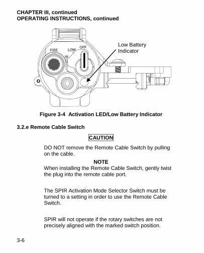
Figure 3-4 Activation LED/Low Battery Indicator
3.2.e Remote Cable Switch
CAUTION
DO NOT remove the Remote Cable Switch by pulling on the cable.
NOTE When installing the Remote Cable Switch, gently twist the plug into the remote cable port. The SPIR Activation Mode Selector Switch must be turned to a setting in order to use the Remote Cable Switch. SPIR will not operate if the rotary switches are not precisely aligned with the marked switch position.
Low Battery Indicator
3-7
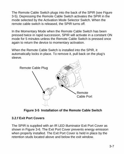
The Remote Cable Switch plugs into the back of the SPIR (see Figure 3-5). Depressing the Remote Cable Switch activates the SPIR in the mode selected by the Activation Mode Selector Switch. When the remote cable switch is released, the SPIR turns off. In the Momentary Mode when the Remote Cable Switch has been pressed twice in rapid succession, SPIR will activate in a constant ON mode for 5 minutes unless the Remote Cable Switch is pressed once again to return the device to momentary activation. When the Remote Cable Switch is installed into the SPIR, it automatically locks in place. To remove it, pull back on the plug’s sleeve.
Figure 3-5 Installation of the Remote Cable Switch
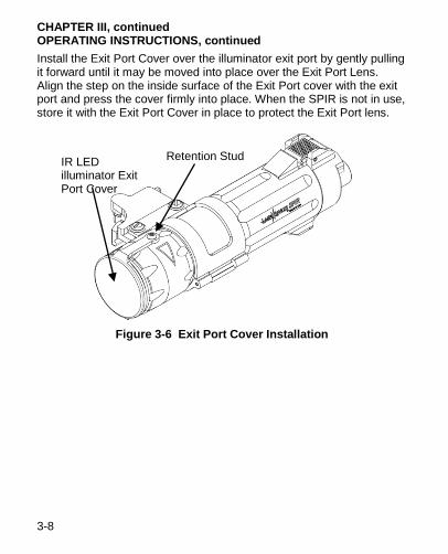
3.2.f Exit Port Covers The SPIR is supplied with an IR LED illuminator Exit Port Cover as shown in Figure 3-6. The Exit Port Cover prevents energy emission when properly installed. The Exit Port Cover is held in place by the retention studs located above and below the exit window.
Remote Cable Plug
Remote Cable Port
CHAPTER III, continued OPERATING INSTRUCTIONS, continued
3-8
Install the Exit Port Cover over the illuminator exit port by gently pulling it forward until it may be moved into place over the Exit Port Lens. Align the step on the inside surface of the Exit Port cover with the exit port and press the cover firmly into place. When the SPIR is not in use, store it with the Exit Port Cover in place to protect the Exit Port lens.
Figure 3-6 Exit Port Cover Installation
IR LED illuminator Exit Port Cover
Retention Stud
CHAPTER III, continued OPERATING INSTRUCTIONS, continued
3-9
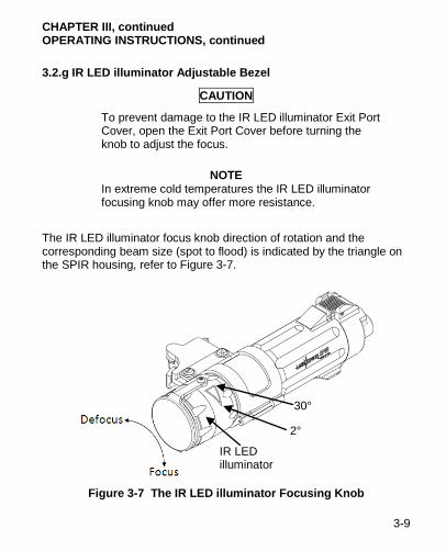
3.2.g IR LED illuminator Adjustable Bezel
CAUTION
To prevent damage to the IR LED illuminator Exit Port Cover, open the Exit Port Cover before turning the knob to adjust the focus.
NOTE
In extreme cold temperatures the IR LED illuminator focusing knob may offer more resistance.
The IR LED illuminator focus knob direction of rotation and the corresponding beam size (spot to flood) is indicated by the triangle on the SPIR housing, refer to Figure 3-7.
Figure 3-7 The IR LED illuminator Focusing Knob
IR LED illuminator
30°
2°
CHAPTER III, continued MOUNTING PROCEDURES, continued
3-10
CHAPTER III
SECTION II MOUNTING PROCEDURES
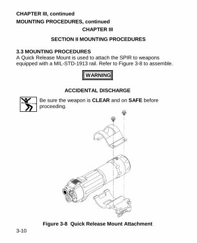
3.3 MOUNTING PROCEDURES A Quick Release Mount is used to attach the SPIR to weapons equipped with a MIL-STD-1913 rail. Refer to Figure 3-8 to assemble.
WARNING
ACCIDENTAL DISCHARGE
Be sure the weapon is CLEAR and on SAFE before proceeding.
Figure 3-8 Quick Release Mount Attachment
3-11
NOTE
The SPIR may be placed at any position (forward and aft) on the rail that is convenient for the user.
When attaching the mount to the SPIR, orient unit in the mount to facilitate battery changes when the SPIR is mounted to the weapon.
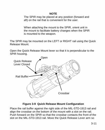
The SPIR may be mounted on the LEFT or RIGHT rail using the Quick Release Mount. Open the Quick Release Mount lever so that it is perpendicular to the SPIR housing.
Figure 3-9 Quick Release Mount Configuration
Place the rail buffer against the right side of the MIL-STD-1913 rail and align the crossbar on the bottom of the mount with a slot on the rail. Push forward on the SPIR so that the crossbar contacts the front of the slot on the MIL-STD-1913 rail. Move the Quick Release Lever arm so
Quick Release Lever Closed
Rail Buffer
Crossbar
Open
CHAPTER III, continued MOUNTING PROCEDURES, continued
3-12
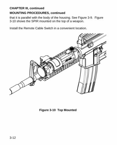
that it is parallel with the body of the housing. See Figure 3-9. Figure 3-10 shows the SPIR mounted on the top of a weapon. Install the Remote Cable Switch in a convenient location.
Figure 3-10 Top Mounted
4-1
4 CHAPTER IV
SECTION I USER PREVENTIVE MAINTENANCE CHECKS
4.1 GENERAL
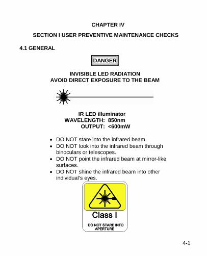
DANGER
INVISIBLE LED RADIATION AVOID DIRECT EXPOSURE TO THE BEAM
IR LED illuminator WAVELENGTH: 850nm OUTPUT: <600mW
• DO NOT stare into the infrared beam. • DO NOT look into the infrared beam through
binoculars or telescopes. • DO NOT point the infrared beam at mirror-like
surfaces. • DO NOT shine the infrared beam into other
individual’s eyes.
CHAPTER IV, continued USER PREVENTIVE MAINTENANCE CHECKS, continued
4-2
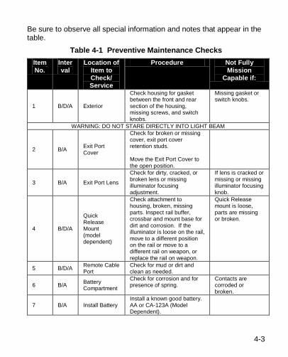
Table 4-1 Preventive Maintenance Checks, has been provided so that you may keep your equipment in good operating condition.
NOTE
Perform functional tests in the order listed in Table 4-1. Operating Procedures are detailed in Chapter III, Section I. Functional testing of the SPIR to ensure proper operation should be performed in a dark room or area away from light. Viewing of IR beam must be performed with a NVD, (AN/PVS-7 or AN/PVS-14).
4.1.a Warnings and Cautions Always observe the WARNINGS and CAUTIONS appearing in the table.
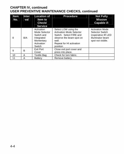
4.1.b Explanation of Table Entries 1. Item Number column. Numbers in this column are for reference. Item numbers also appear in the order that you must perform the checks and services listed. 2. Interval column. This column tells you when you must do the procedure in the procedure column. BEFORE (B) PROCEDURES must be done before you operate or use the equipment. DURING (D) PROCEDURES must be done during the time you are operating or using the equipment. AFTER (A) PROCEDURES must be done immediately after you have operated or used the equipment. 3. Location Item to Check/Service column. This column provides the location and the item to be checked or serviced. 4. Procedure column. This column provides the procedures you must perform. 5. Not Fully Mission Capable If column. Information in this column tells you what faults will keep your equipment from being capable of performing its primary mission.
4-3
Be sure to observe all special information and notes that appear in the table.
Table 4-1 Preventive Maintenance Checks Item No.
Interval
Location of Item to Check/ Service
Procedure Not Fully Mission
Capable if:
1 B/D/A Exterior
Check housing for gasket between the front and rear section of the housing, missing screws, and switch knobs.
Missing gasket or switch knobs.
WARNING: DO NOT STARE DIRECTLY INTO LIGHT BEAM
2 B/A Exit Port Cover
Check for broken or missing cover, exit port cover retention studs. Move the Exit Port Cover to the open position.
3 B/A Exit Port Lens
Check for dirty, cracked, or broken lens or missing illuminator focusing adjustment.
If lens is cracked or missing or missing illuminator focusing knob.
4 B/D/A
Quick Release Mount (model dependent)
Check attachment to housing, broken, missing parts. Inspect rail buffer, crossbar and mount base for dirt and corrosion. If the illuminator is loose on the rail, move to a different position on the rail or move to a different rail on weapon, or replace the rail on weapon.
Quick Release mount is loose, parts are missing or broken.
5 B/D/A Remote Cable Port
Check for mud or dirt and clean as needed.
6 B/A Battery Compartment
Check for corrosion and for presence of spring.
Contacts are corroded or broken.
7 B/A Install Battery Install a known good battery. AA or CA-123A (Model Dependent).
CHAPTER IV, continued USER PREVENTIVE MAINTENANCE CHECKS, continued
4-4
Item No.
Interval
Location of Item to Check/ Service
Procedure Not Fully Mission
Capable if:
8 B/A
Activation Mode Selector Switch and Integrated Momentary Activation Switch
Select LOW using the Activation Mode Selector Switch. Select FIRE and observe the beam spot on wall. Repeat for HI activation position.
Activation Mode Selector Switch inoperative IR LED illuminator beam spot not visible.
9 B Exit Port Cover
Close exit port cover and press into place.
10 A Textile Bag Check for torn fabric. 11 A Battery Remove battery.
4-5
CHAPTER IV
SECTION II TROUBLESHOOTING
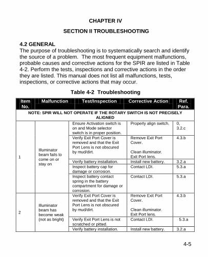
4.2 GENERAL The purpose of troubleshooting is to systematically search and identify the source of a problem. The most frequent equipment malfunctions, probable causes and corrective actions for the SPIR are listed in Table 4-2. Perform the tests, inspections and corrective actions in the order they are listed. This manual does not list all malfunctions, tests, inspections, or corrective actions that may occur.
Table 4-2 Troubleshooting Item No.
Malfunction Test/Inspection Corrective Action Ref. Para.
NOTE: SPIR WILL NOT OPERATE IF THE ROTARY SWITCH IS NOT PRECISELY ALIGNED
1
Illuminator beam fails to come on or stay on
Ensure Activation switch is on and Mode selector switch is in proper position.
Properly align switch. 0, 3.2.c
Verify Exit Port Cover is removed and that the Exit Port Lens is not obscured by mud/dirt.
Remove Exit Port Cover. Clean illuminator. Exit Port lens.
4.3.b
Verify battery installation. Install new battery. 3.2.a Inspect battery cap for damage or corrosion.
Contact LDI. 5.3.a
Inspect battery contact spring in the battery compartment for damage or corrosion.
Contact LDI. 5.3.a
2
Illuminator beam has become weak (not as bright)
Verify Exit Port Cover is removed and that the Exit Port Lens is not obscured by mud/dirt.
Remove Exit Port Cover. Clean illuminator. Exit Port lens.
4.3.b
Verify Exit Port Lens is not scratched or pitted.
Contact LDI. 5.3.a
Verify battery installation. Install new battery. 3.2.a
CHAPTER IV, continued TROUBLESHOOTING, continued
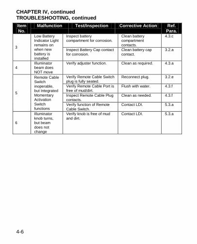
4-6
Item No.
Malfunction Test/Inspection Corrective Action Ref. Para.
3
Low Battery Indicator Light remains on when new battery is installed
Inspect battery compartment for corrosion.
Clean battery compartment contacts.
4.3.c
Inspect Battery Cap contact for corrosion.
Clean battery cap contact.
3.2.a
4 Illuminator beam does NOT move
Verify adjuster function. Clean as required. 4.3.a
5
Remote Cable Switch inoperable, but Integrated Momentary Activation Switch functions
Verify Remote Cable Switch plug is fully seated.
Reconnect plug. 3.2.e
Verify Remote Cable Port is free of mud/dirt.
Flush with water. 4.3.f
Inspect Remote Cable Plug contacts.
Clean as needed. 4.3.f
Verify function of Remote Cable Switch.
Contact LDI. 5.3.a
6
Illuminator knob turns, but beam does not change
Verify knob is free of mud and dirt.
Contact LDI. 5.3.a
4-7
CHAPTER IV
SECTION III MAINTENANCE
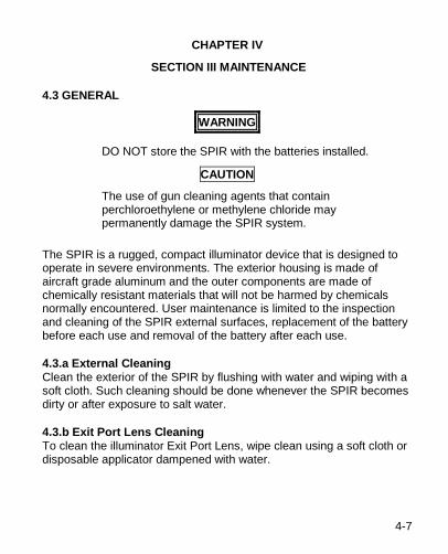
4.3 GENERAL
WARNING
DO NOT store the SPIR with the batteries installed.
CAUTION
The use of gun cleaning agents that contain perchloroethylene or methylene chloride may permanently damage the SPIR system.
The SPIR is a rugged, compact illuminator device that is designed to operate in severe environments. The exterior housing is made of aircraft grade aluminum and the outer components are made of chemically resistant materials that will not be harmed by chemicals normally encountered. User maintenance is limited to the inspection and cleaning of the SPIR external surfaces, replacement of the battery before each use and removal of the battery after each use.
4.3.a External Cleaning Clean the exterior of the SPIR by flushing with water and wiping with a soft cloth. Such cleaning should be done whenever the SPIR becomes dirty or after exposure to salt water.
4.3.b Exit Port Lens Cleaning To clean the illuminator Exit Port Lens, wipe clean using a soft cloth or disposable applicator dampened with water.
CHAPTER IV, continued MAINTENANCE, continued
4-8
4.3.c Battery Compartment Before each use, inspect the battery and battery compartment for dirt, dust or corrosion. If dirty, clean using a soft cloth or disposable applicator.
4.3.d Battery Compartment Inspect the battery cap and housing for contamination. If it appears to be oily or dirty, clean with Isopropyl Alcohol using a soft, clean cloth.
4.3.e Battery Removal and Replacement Refer to Chapter III, Section I, Paragraph 3.2.a for Battery Installation procedures. No special tools or equipment are required to replace the battery.
4.3.f Remote Cable Port Before each use, inspect the remote cable port for dirt, dust or corrosion. Thoroughly clean the receptacle by flushing with water then wipe with a soft cloth or disposable applicator.
4.4 REMOVAL AND REPLACEMENT OF PARTS Maintenance is authorized for the removal and replacement of a limited number of assemblies. Special tools or equipment are not required for maintaining the SPIR.
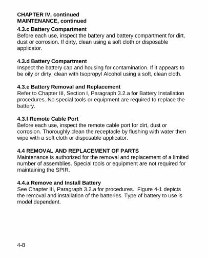
4.4.a Remove and Install Battery See Chapter III, Paragraph 3.2.a for procedures. Figure 4-1 depicts the removal and installation of the batteries. Type of battery to use is model dependent.
4-9
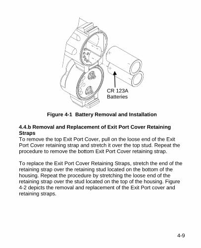
Figure 4-1 Battery Removal and Installation
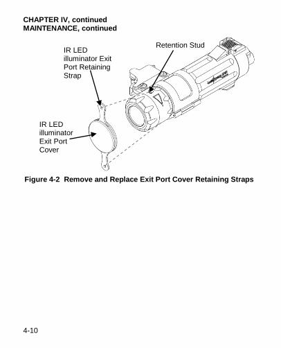
4.4.b Removal and Replacement of Exit Port Cover Retaining Straps To remove the top Exit Port Cover, pull on the loose end of the Exit Port Cover retaining strap and stretch it over the top stud. Repeat the procedure to remove the bottom Exit Port Cover retaining strap. To replace the Exit Port Cover Retaining Straps, stretch the end of the retaining strap over the retaining stud located on the bottom of the housing. Repeat the procedure by stretching the loose end of the retaining strap over the stud located on the top of the housing. Figure 4-2 depicts the removal and replacement of the Exit Port cover and retaining straps.
CR 123A Batteries
CHAPTER IV, continued MAINTENANCE, continued
4-10
Figure 4-2 Remove and Replace Exit Port Cover Retaining Straps
IR LED illuminator Exit Port Retaining Strap
Retention Stud
IR LED illuminator Exit Port Cover
5-1
5 CHAPTER V
SERVICE/PACKING AND UNPACKING
5.1 WARRANTY INFORMATION Laser Devices, Inc. will furnish its standard form LIMITED WARRANTY in favor of its customers and the first end users of its products. The terms of the warranty are as follows: All LDI manufactured products (excluding flashlight bulbs, borelight inserts, batteries and other items that are ordinarily consumed during the normal use of the product) have a ONE (1) year limited warranty on parts and workmanship from the date of purchase. The warranty is void if the serial number or the manufacturer’s labels affixed to the product have been removed or if the product has been misused, modified, neglected or has been disassembled prior to return to the manufacturer. LDI will repair or replace defective products at its discretion. To the maximum extent permitted by law, LDI’s election to repair or replace the device shall constitute the purchaser’s sole remedy in the event of a defect. LDI disclaims all other warranties, expressed or implied, including but not limited to implied warranties of merchantability and fitness for a particular purpose. Moreover, to the maximum extent permitted by law, LDI on behalf of itself, its suppliers, distributors, dealers and agents disclaims any and all other liability for damages, including without limitation, actual damages, consequential damages and indirect damages, for personal injury, wrongful death, pecuniary loss and any other physical or financial loss arising out of the use or the inability to use any LDI product even if Laser Devices, Inc. has been advised of the possibility of such damages. This limited warranty gives the purchaser specific legal rights which may vary by state and jurisdiction.
5.2 NON-WARRANTY INFORMATION Non-warranty repairs are subject to an evaluation fee. SPIR devices that are not covered by the warranty will be tested and evaluated for failure. Customer permission and payment terms will be obtained prior to performing any repairs.
SERVICE/PACKING AND UNPACKING, continued
5-2
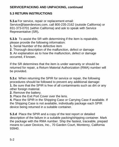
5.3 RETURN INSTRUCTIONS
5.3.a For service, repair or replacement email: [email protected], call 800-235-2162 (outside California) or 831-373-0701 (within California) and ask to speak with Service Representative (SR). 5.3.b To assist the SR with determining if the item is repairable, please provide the following information: 1. Serial Number of the defective item 2. Thorough description of the malfunction, defect or damage 3. An explanation as to how the malfunction, defect or damage occurred, if known. If the SR determines that the item is under warranty or should be returned for repair, a Return Material Authorization (RMA) number will be provided. 5.3.c When returning the SPIR for service or repair, the following procedures should be followed to prevent any additional damage: 1. Be sure that the SPIR is free of all contaminants such as dirt or any other foreign material. 2. Remove the battery. 3. Place the Exit Port Cover over the lens. 4. Place the SPIR in the Shipping Case or Carrying Case if available. If the Shipping Case is not available, individually package each SPIR device being returned in a suitable container. 5.3.d Place the SPIR and a copy of the test report or detailed description of the failure in a suitable packing/shipping container. Mark the package with the RMA number. Ship the fastest, traceable, prepaid means to Laser Devices, Inc., 70 Garden Court, Monterey, California 93940.
A-1
A APPENDIX A
REPAIR PARTS
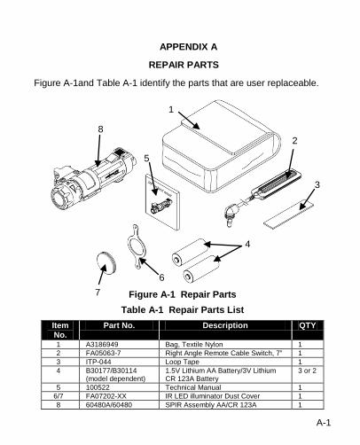
Figure A-1and Table A-1 identify the parts that are user replaceable.
Figure A-1 Repair Parts
Table A-1 Repair Parts List Item No.
Part No. Description QTY
1 A3186949 Bag, Textile Nylon 1 2 FA05063-7 Right Angle Remote Cable Switch, 7” 1 3 ITP-044 Loop Tape 1 4 B30177/B30114
(model dependent) 1.5V Lithium AA Battery/3V Lithium CR 123A Battery
3 or 2
5 100522 Technical Manual 1 6/7 FA07202-XX IR LED illuminator Dust Cover 1 8 60480A/60480 SPIR Assembly AA/CR 123A 1
1
2
3
4
5
6 7
8
70 Garden Court • Monterey, CA 93940 Tel 831-373-0701/800-235-2162 (outside CA) Fax 831-373-0903 [email protected] • www.laserdevices.com
© 2013 Laser Devices, Inc. P/N 100522
V4