Embed Size (px)
Citation preview
Technical ManualEIGHTH EDITION
Publication No: EN-ODY-TM-0002 - February 2015www.odysseybattery.com
Publication No: EN-ODY-TM-0002 - February 2015www.odysseybattery.com2
ODYSSEY® Battery Technical Manual – Eighth Edition
TABLE OF CONTENTS
Introduction 3
Why use ODYSSEY® batteries? 3
Extended discharge characteristics 4
Performance data tables 4
Cycle Life and Depth of Discharge (DOD) 11
Float Life 11
ODYSSEY® battery storage and deep discharge recovery 11 (A) How do I know the state of charge (SOC) of the battery? 11 (B) How long can the battery be stored? 12 (C) Can the battery recover from abusive storage conditions? 12 (1) German DIN standard test for overdischarge recovery 12 (2) High temperature discharged storage test 12
Parasitic loads 13
Shock, impact and vibration testing 13 (A) Caterpillar™ 100-hour vibration test 13 (B) Shock and vibration test per IEC 61373, Sections 8-10 13
Charging ODYSSEY® batteries 13 (A) Selecting the right charger for your battery 14 (B) Selecting battery type on your charger 15
Rapid charging of ODYSSEY® batteries 15
Load test procedure 16
ODYSSEY® batteries in no-idle applications 16
Parallel connections 17
Ventilation 17
Concluding remarks 17
Frequently asked SLI battery questions 18
Preface to the Eighth Edition
As with previous manuals, this latest edition of the ODYSSEY® Battery technical manual includes detailed performance data for the complete line of ODYSSEY® batteries. Updated test data will help ensure selection of the correct battery for every application.
In addition, this manual includes an expanded section on charging requirements for ODYSSEY batteries. This includes detailed information about the three-step charge profile that will restore a fully discharged battery to optimum power in about 6 to 8 hours.
You may notice that we’ve updated the look of ODYSSEY batteries to differentiate this premium line in the marketplace. You’ll be pleased to know that beneath the surface is the same industry-leading technology, including Thin Plate Pure Lead (TPPL) construction, that has made ODYSSEY batteries the choice of knowledgeable automotive technicians and consumers nationwide.
www.odysseybattery.com 3Publication No: EN-ODY-TM-0002 - February 2015
INTRODUCTION
The ODYSSEY® battery ingeniously uses Absorbed Glass Mat (AGM) Valve Regulated Lead Acid (VRLA) technology to offer, in one package, the characteristics of two separate batteries. It can deep cycle as well as deliver serious cranking power. Traditional battery designs allow them to either deep cycle or provide high amperage discharges for applications such as engine starting. The ODYSSEY battery can support applications in either category. ODYSSEY batteries are capable of providing engine cranking pulses of up to 2,250A (PC2250) for 5 seconds at 25ºC as well as deliver 400 charge/discharge cycles to 80% depth of discharge (DOD) when properly charged. A typical starting, lighting and ignition (SLI) battery, for example, is designed to provide short-duration, high-amperage pulses; it performs poorly when repeatedly taken down to deep depths of discharge or if they are placed on a continuous trickle charge, such as when they are used to crank a backup generator. A traditional battery resembles either a sprinter or a long distance runner; an ODYSSEY battery will do both – provide short duration high amperage pulses or low rate, long duration drains.
WHY USE ODYSSEY® BATTERIES?
Guaranteed longer service life
With an 8- to 12-year design life in float (emergency power) applications at 25ºC and a 3- to 10-year service life depending on the nature of the non-float applications, ODYSSEY batteries save you time and money because you do not have to replace them as often. Unlike other AGM VRLA batteries, the ODYSSEY battery is capable of delivering up to 400 cycles when discharged to 80% DOD and properly charged.
Longer storage life
Unlike conventional batteries that need a recharge every 6 to 12 weeks, a fully charged ODYSSEY battery can be stored for up to 2 years at 25ºC from a full state of charge. At lower temperatures, storage times will be even longer.
Deep discharge recovery
The ease with which an ODYSSEY battery can recover from a deep discharge is extraordinary. A later section on storage and recharge criteria discusses test data on this important topic.
Superior cranking and fast charge capability
The cranking power of ODYSSEY batteries is superior to that of equally sized conventional batteries, even when the temperature is as low as -40ºC. In addition, with simple constant voltage charging there is no need to limit the inrush current, allowing the battery to be rapidly charged. Please see the section titled Rapid charging of ODYSSEY batteries for more details on this feature.
Easy shipping
The AGM valve-regulated design of the ODYSSEY battery eliminates the need for vent tubes; further, no battery watering is required and there is no fear of acid burns or damage to expensive chrome or paint. Because of the starved electrolyte design, the ODYSSEY battery has been proven to meet the US Department of Transportation (USDOT) criteria for a non-spillable battery. They can be shipped by road, air or sea.
Tough construction
The rugged construction of the ODYSSEY battery makes it suitable for use in a variety of environments ranging from marine to trucks and powersports applications.
Mounting flexibility
Installing the ODYSSEY battery in any orientation other than inverted does not affect any performance attribute. There is also no fear of acid spillage.
Superior vibration resistance
ODYSSEY batteries have passed a variety of rigorous tests that demonstrate their ruggedness and exceptional tolerance of mechanical abuse. Please see the section titled Shock, Impact and Vibration testing for more details on these tests.
Ready out of the box
ODYSSEY batteries ship from the factory fully charged. If the battery’s open circuit voltage is higher than 12.65V, simply install it in your vehicle and you are ready to go; if below 12.65V boost charge the battery following the instructions in this manual or the owner’s manual. For optimum reliability, a boost charge prior to installation is recommended, regardless of the battery’s open circuit voltage (OCV).
Publication No: EN-ODY-TM-0002 - February 2015www.odysseybattery.com4
PC310 performance data at 25°C, per 12V module
Watts
1000
100
10
1
0.10.01 0.1 1 10 100
Hours to 10.02V @ 25ºC
Wat
ts o
r am
ps p
er 1
2V u
nit
Amps 2 min 738 80.8 2.7 24.6 613.2 20.4 273.3 9.15 min 473 43.2 3.6 39.4 393.3 32.8 175.3 14.610 min 312 26.0 4.4 53.1 259.4 44.1 115.6 19.715 min 236 19.0 4.8 59.0 196.0 49.0 87.4 21.820 min 191 15.0 5.0 62.9 158.4 52.3 70.6 23.330 min 139 10.8 5.4 69.3 115.1 57.6 51.3 25.745 min 98 7.6 5.7 73.9 81.8 61.4 36.5 27.41 hr 76 6.0 6.0 76.4 63.5 63.5 28.3 28.32 hr 41 3.2 6.5 81.0 33.7 67.3 15.0 30.03 hr 28 2.3 6.8 82.8 22.9 68.8 10.2 30.74 hr 21 1.8 7.0 83.7 17.4 69.6 7.8 31.05 hr 17 1.4 7.2 84.5 14.0 70.2 6.3 31.38 hr 11 0.9 7.6 86.1 8.9 71.5 4.0 31.910 hr 9 0.8 7.8 86.8 7.2 72.1 3.2 32.220 hr 5 0.4 8.6 90.5 3.8 75.2 1.7 33.5
Time Watts Amps Capacity Energy (W) (A) (Ah) (Wh) W/liter Wh/liter W/kg Wh/kg
ENERGY AND POWER DENSITIES
PC370 performance data at 25°C, per 12V module
Wat
ts o
r am
ps p
er 1
2V u
nit
Hours to 10.02V @ 25ºC
1000
100
10
1
00.01 0.1 1 10 100
Watts Amps
Time Watts(W)
Amps(A)
Capacity(Ah)
Energy(Wh)
ENERGY AND POWER DENSITIES
W/litre Wh/litre W/kg Wh/kg
2 min 1320 127.1 4.2 44.0 612.2 20.4 231.6 7.75 min 768 70.7 5.9 64.0 356.2 29.7 134.7 11.210 min 485 43.6 7.3 80.9 225.1 37.5 85.2 14.215 min 365 32.4 8.1 91.4 169.5 42.4 64.1 16.020 min 297 26.1 8.7 99.0 137.8 45.9 52.1 17.430 min 220 19.1 9.6 109.8 101.9 50.9 38.5 19.345 min 161 13.8 10.4 120.6 74.6 55.9 28.2 21.21 hr 128 10.9 10.9 127.8 59.3 59.3 22.4 22.42 hr 73 6.1 12.2 145.2 33.7 67.3 12.7 25.53 hr 51 4.3 12.9 153.7 23.8 71.3 9.0 27.04 hr 40 3.3 13.3 159.6 18.5 74.0 7.0 28.05 hr 33 2.7 13.7 163.8 15.2 76.0 5.7 28.78 hr 21 1.8 14.4 171.8 10.0 79.7 3.8 30.110 hr 18 1.5 14.5 175.2 8.1 81.3 3.1 30.720 hr 9 0.8 15.2 183.6 4.3 85.2 1.6 32.2
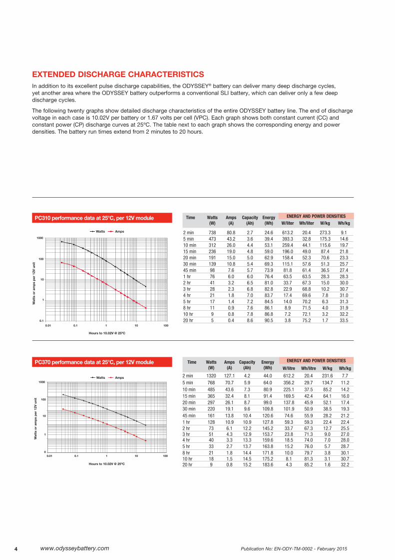
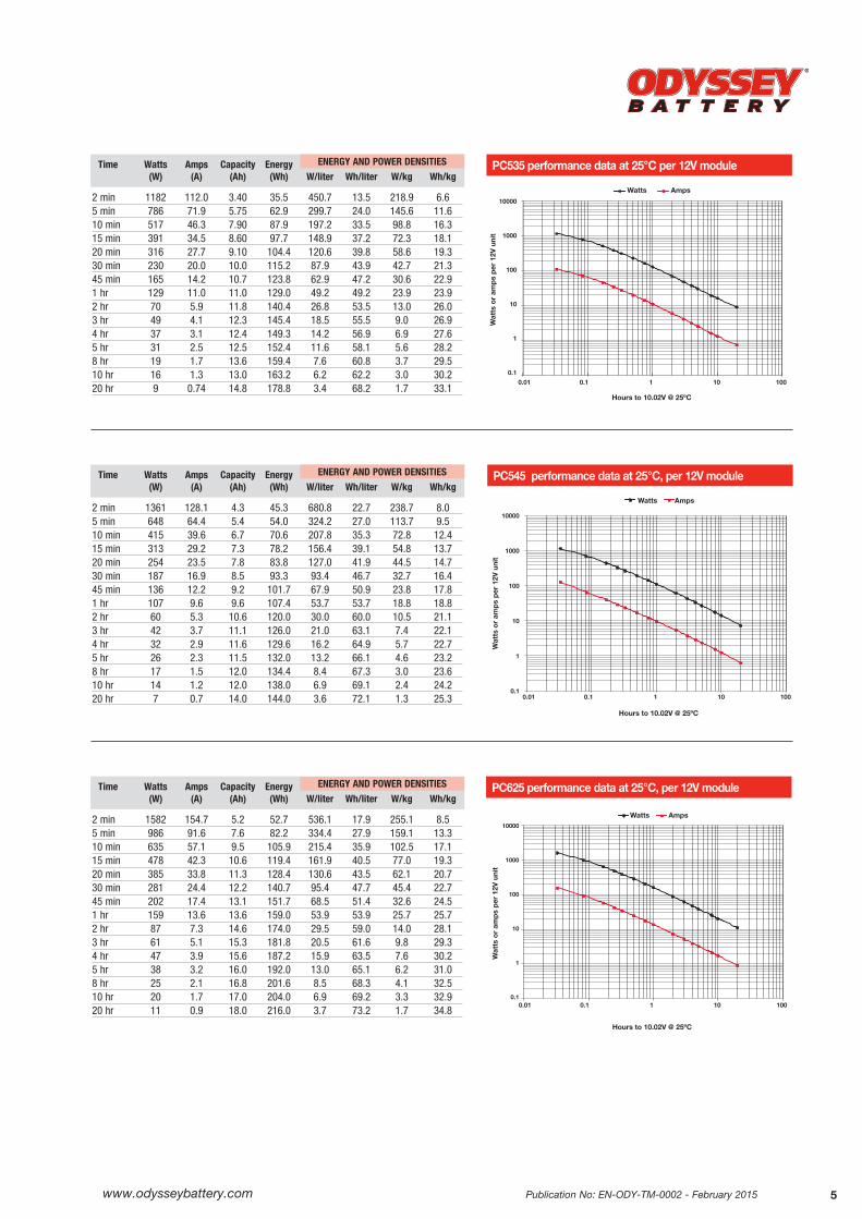
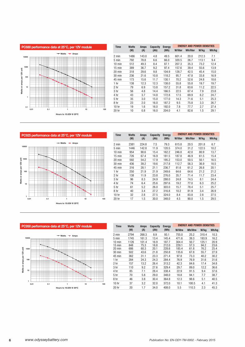
EXTENDED DISCHARGE CHARACTERISTICSIn addition to its excellent pulse discharge capabilities, the ODYSSEY® battery can deliver many deep discharge cycles, yet another area where the ODYSSEY battery outperforms a conventional SLI battery, which can deliver only a few deep discharge cycles.
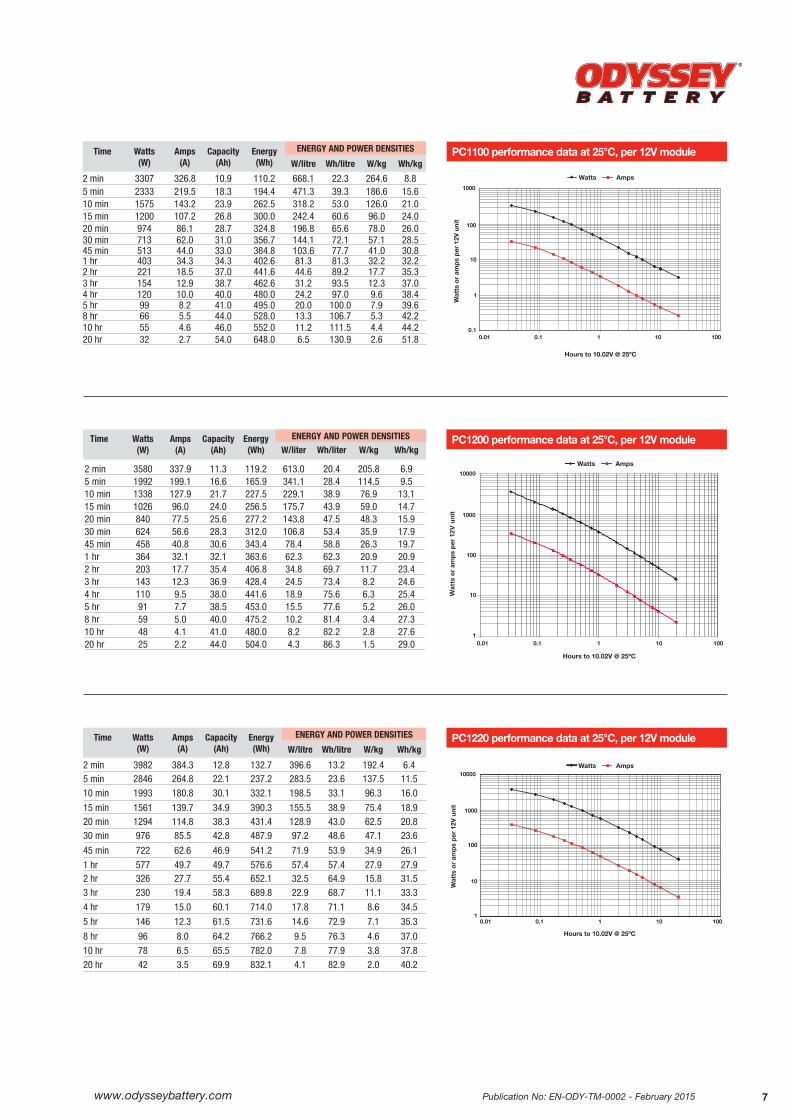
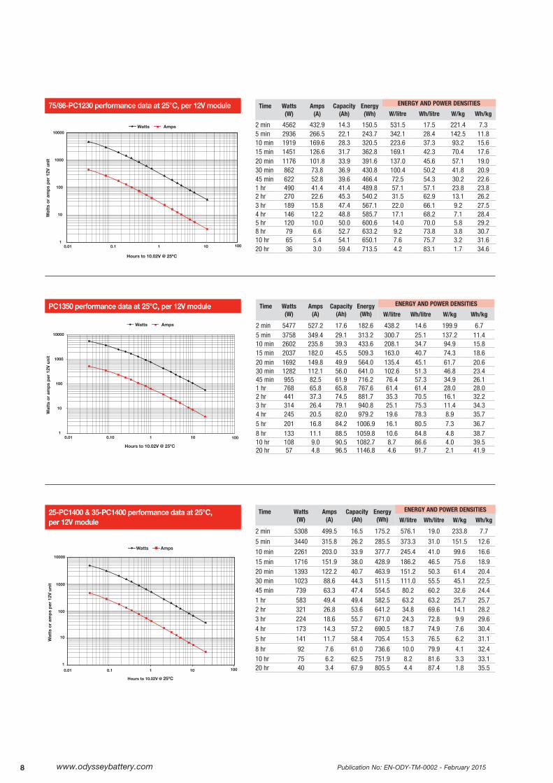
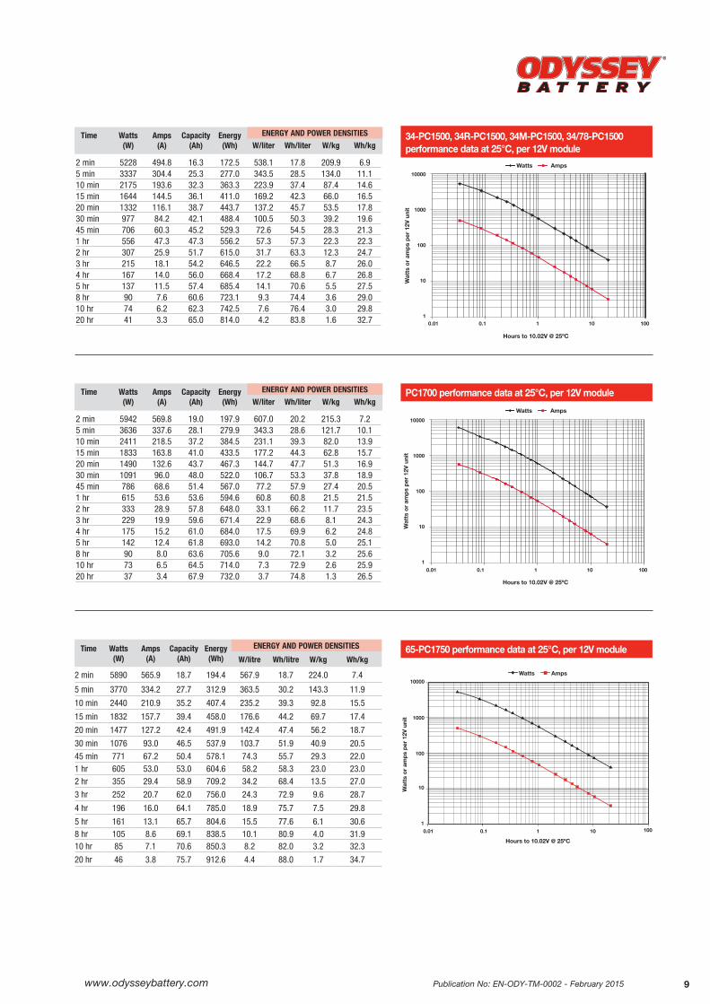
The following twenty graphs show detailed discharge characteristics of the entire ODYSSEY battery line. The end of discharge voltage in each case is 10.02V per battery or 1.67 volts per cell (VPC). Each graph shows both constant current (CC) and constant power (CP) discharge curves at 25ºC. The table next to each graph shows the corresponding energy and power densities. The battery run times extend from 2 minutes to 20 hours.
www.odysseybattery.com 5Publication No: EN-ODY-TM-0002 - February 2015
Wat
ts o
r am
ps p
er 1
2V u
nit
10000
1000
100
10
1
0.10.01 0.1 1 10 100
Hours to 10.02V @ 25ºC
Watts Amps
PC545 performance data at 25°C, per 12V module
2 min 1361 128.1 4.3 45.3 680.8 22.7 238.7 8.05 min 648 64.4 5.4 54.0 324.2 27.0 113.7 9.510 min 415 39.6 6.7 70.6 207.8 35.3 72.8 12.415 min 313 29.2 7.3 78.2 156.4 39.1 54.8 13.720 min 254 23.5 7.8 83.8 127.0 41.9 44.5 14.730 min 187 16.9 8.5 93.3 93.4 46.7 32.7 16.445 min 136 12.2 9.2 101.7 67.9 50.9 23.8 17.81 hr 107 9.6 9.6 107.4 53.7 53.7 18.8 18.82 hr 60 5.3 10.6 120.0 30.0 60.0 10.5 21.13 hr 42 3.7 11.1 126.0 21.0 63.1 7.4 22.14 hr 32 2.9 11.6 129.6 16.2 64.9 5.7 22.75 hr 26 2.3 11.5 132.0 13.2 66.1 4.6 23.28 hr 17 1.5 12.0 134.4 8.4 67.3 3.0 23.610 hr 14 1.2 12.0 138.0 6.9 69.1 2.4 24.220 hr 7 0.7 14.0 144.0 3.6 72.1 1.3 25.3
Time Watts Amps Capacity Energy (W) (A) (Ah) (Wh) W/liter Wh/liter W/kg Wh/kg
ENERGY AND POWER DENSITIES
PC535 performance data at 25°C per 12V module
Wat
ts o
r am
ps p
er 1
2V u
nit
10000
1000
100
10
1
0.1
Watts Amps
Hours to 10.02V @ 25ºC
0.01 0.1 1 10 100
2 min 1182 112.0 3.40 35.5 450.7 13.5 218.9 6.65 min 786 71.9 5.75 62.9 299.7 24.0 145.6 11.610 min 517 46.3 7.90 87.9 197.2 33.5 98.8 16.315 min 391 34.5 8.60 97.7 148.9 37.2 72.3 18.120 min 316 27.7 9.10 104.4 120.6 39.8 58.6 19.330 min 230 20.0 10.0 115.2 87.9 43.9 42.7 21.345 min 165 14.2 10.7 123.8 62.9 47.2 30.6 22.91 hr 129 11.0 11.0 129.0 49.2 49.2 23.9 23.92 hr 70 5.9 11.8 140.4 26.8 53.5 13.0 26.03 hr 49 4.1 12.3 145.4 18.5 55.5 9.0 26.94 hr 37 3.1 12.4 149.3 14.2 56.9 6.9 27.65 hr 31 2.5 12.5 152.4 11.6 58.1 5.6 28.28 hr 19 1.7 13.6 159.4 7.6 60.8 3.7 29.510 hr 16 1.3 13.0 163.2 6.2 62.2 3.0 30.220 hr 9 0.74 14.8 178.8 3.4 68.2 1.7 33.1
Time Watts Amps Capacity Energy (W) (A) (Ah) (Wh) W/liter Wh/liter W/kg Wh/kg
ENERGY AND POWER DENSITIES
10000
1000
100
10
1
0.1
Wat
ts o
r am
ps p
er 1
2V u
nit
Hours to 10.02V @ 25ºC
Watts Amps
0.01 0.1 1 10 100
PC625 performance data at 25°C, per 12V module
2 min 1582 154.7 5.2 52.7 536.1 17.9 255.1 8.55 min 986 91.6 7.6 82.2 334.4 27.9 159.1 13.310 min 635 57.1 9.5 105.9 215.4 35.9 102.5 17.115 min 478 42.3 10.6 119.4 161.9 40.5 77.0 19.320 min 385 33.8 11.3 128.4 130.6 43.5 62.1 20.730 min 281 24.4 12.2 140.7 95.4 47.7 45.4 22.745 min 202 17.4 13.1 151.7 68.5 51.4 32.6 24.51 hr 159 13.6 13.6 159.0 53.9 53.9 25.7 25.72 hr 87 7.3 14.6 174.0 29.5 59.0 14.0 28.13 hr 61 5.1 15.3 181.8 20.5 61.6 9.8 29.34 hr 47 3.9 15.6 187.2 15.9 63.5 7.6 30.25 hr 38 3.2 16.0 192.0 13.0 65.1 6.2 31.08 hr 25 2.1 16.8 201.6 8.5 68.3 4.1 32.510 hr 20 1.7 17.0 204.0 6.9 69.2 3.3 32.920 hr 11 0.9 18.0 216.0 3.7 73.2 1.7 34.8
Time Watts Amps Capacity Energy (W) (A) (Ah) (Wh) W/liter Wh/liter W/kg Wh/kg
ENERGY AND POWER DENSITIES
Publication No: EN-ODY-TM-0002 - February 2015www.odysseybattery.com6
PC925 performance data at 25°C, per 12V module
Wat
ts o
r am
ps p
er 1
2V u
nit
10000
1000
100
10
1
Watts Amps
0.01 0.1 1 10 100
Hours to 10.02V @ 25ºC
2 min 2381 224.8 7.5 79.3 615.8 20.5 201.8 6.75 min 1446 142.8 11.9 120.5 374.0 31.2 122.5 10.210 min 954 90.6 15.4 162.2 246.8 42.0 80.9 13.715 min 726 67.4 16.9 181.5 187.8 46.9 61.5 15.420 min 592 54.2 17.9 195.2 153.0 50.5 50.1 16.530 min 436 39.2 19.6 217.8 112.7 56.3 36.9 18.545 min 316 28.1 21.1 236.7 81.6 61.2 26.8 20.11 hr 250 21.9 21.9 249.6 64.6 64.6 21.2 21.22 hr 138 11.9 23.8 276.0 35.7 71.4 11.7 23.43 hr 96 8.3 24.9 288.0 24.8 74.5 8.1 24.44 hr 74 6.4 25.6 297.6 19.2 77.0 6.3 25.25 hr 61 5.2 26.0 303.0 15.7 78.4 5.1 25.78 hr 40 3.4 27.2 316.8 10.2 81.9 3.4 26.910 hr 32 2.8 27.5 324.0 8.4 83.8 2.8 27.520 hr 17 1.5 30.0 348.0 4.5 90.0 1.5 29.5
Time Watts Amps Capacity Energy (W) (A) (Ah) (Wh) W/liter Wh/liter W/kg Wh/kg
ENERGY AND POWER DENSITIES
PC680 performance data at 25°C, per 12V module
Wat
ts o
r am
ps p
er 1
2V u
nit
10000
1000
100
10
1
0.1
Watts Amps
Hours to 10.02V @ 25ºC
0.01 0.1 1 10 100
2 min 1486 143.0 4.8 49.5 601.4 20.0 212.3 7.15 min 792 78.8 6.6 66.0 320.5 26.7 113.1 9.410 min 512 49.3 8.4 87.1 207.3 35.3 73.2 12.415 min 389 36.7 9.2 97.4 157.6 39.4 55.6 13.920 min 318 29.6 9.8 104.9 128.7 42.5 45.4 15.030 min 236 21.6 10.8 118.2 95.7 47.8 33.8 16.945 min 173 15.6 11.7 130.1 70.2 52.6 24.8 18.61 hr 138 12.3 12.3 138.0 55.8 55.8 19.7 19.72 hr 79 6.9 13.8 157.2 31.8 63.6 11.2 22.53 hr 56 4.8 14.4 166.5 22.5 67.4 7.9 23.84 hr 43 3.7 14.8 172.8 17.5 69.9 6.2 24.75 hr 35 3.0 15.0 177.0 14.3 71.6 5.1 25.38 hr 23 2.0 16.0 187.2 9.5 75.8 3.3 26.710 hr 19 1.6 16.0 192.0 7.8 77.7 2.7 27.420 hr 10 0.8 16.0 204.0 4.1 82.6 1.5 29.1
Time Watts Amps Capacity Energy (W) (A) (Ah) (Wh) W/liter Wh/liter W/kg Wh/kg
ENERGY AND POWER DENSITIES
1
10
100
1000
10000
Wat
ts o
r am
ps p
er 1
2V u
nit
Hours to 10.02V @ 25ºC
0.01 0.1 1 10 100
Watts Amps
PC950 performance data at 25°C, per 12V module Time Watts(W)
Amps(A)
Capacity(Ah)
Energy(Wh)
ENERGY AND POWER DENSITIES
W/litre Wh/litre W/kg Wh/kg
2 min 2794 268.3 8.9 93.1 755.0 25.2 310.4 10.35 min 1745 161.3 13.4 145.4 471.6 39.3 193.9 16.210 min 1126 101.4 16.9 187.7 304.4 50.7 125.1 20.915 min 848 75.3 18.8 212.0 229.1 57.3 94.2 23.620 min 686 60.3 20.1 228.6 185.4 61.8 76.2 25.430 min 502 43.6 21.8 250.8 135.6 67.8 55.7 27.945 min 362 31.1 23.3 271.4 97.8 73.3 40.2 30.21 hr 284 24.3 24.3 284.4 76.9 76.9 31.6 31.62 hr 157 13.2 26.4 313.2 42.3 84.6 17.4 34.83 hr 110 9.2 27.6 329.4 29.7 89.0 12.2 36.64 hr 85 7.1 28.4 338.4 22.9 91.5 9.4 37.65 hr 70 5.8 29.0 348.0 18.8 94.1 7.7 38.78 hr 46 3.8 30.4 364.8 12.3 98.6 5.1 40.510 hr 37 3.2 32.0 372.0 10.1 100.5 4.1 41.320 hr 20 1.7 34.0 408.0 5.5 110.3 2.3 45.3
www.odysseybattery.com 7Publication No: EN-ODY-TM-0002 - February 2015
PC1100 performance data at 25°C, per 12V module
Wat
ts o
r am
ps p
er 1
2V u
nit
Hours to 10.02V @ 25ºC
0.01 0.1 1 10 100
1000
100
10
1
0.1
Watts Amps
Time Watts(W)
Amps(A)
Capacity(Ah)
Energy(Wh)
ENERGY AND POWER DENSITIES
W/litre Wh/litre W/kg Wh/kg
2 min 3307 326.8 10.9 110.2 668.1 22.3 264.6 8.85 min 2333 219.5 18.3 194.4 471.3 39.3 186.6 15.610 min 1575 143.2 23.9 262.5 318.2 53.0 126.0 21.015 min 1200 107.2 26.8 300.0 242.4 60.6 96.0 24.020 min 974 86.1 28.7 324.8 196.8 65.6 78.0 26.030 min 713 62.0 31.0 356.7 144.1 72.1 57.1 28.545 min 513 44.0 33.0 384.8 103.6 77.7 41.0 30.81 hr 403 34.3 34.3 402.6 81.3 81.3 32.2 32.22 hr 221 18.5 37.0 441.6 44.6 89.2 17.7 35.33 hr 154 12.9 38.7 462.6 31.2 93.5 12.3 37.04 hr 120 10.0 40.0 480.0 24.2 97.0 9.6 38.45 hr 99 8.2 41.0 495.0 20.0 100.0 7.9 39.68 hr 66 5.5 44.0 528.0 13.3 106.7 5.3 42.210 hr 55 4.6 46.0 552.0 11.2 111.5 4.4 44.220 hr 32 2.7 54.0 648.0 6.5 130.9 2.6 51.8
PC1200 performance data at 25°C, per 12V moduleW
atts
or
amp
s p
er 1
2V u
nit
Watts Amps
Hours to 10.02V @ 25ºC
0.01 0.1 1 10 100
10000
1000
100
10
1
2 min 3580 337.9 11.3 119.2 613.0 20.4 205.8 6.95 min 1992 199.1 16.6 165.9 341.1 28.4 114.5 9.510 min 1338 127.9 21.7 227.5 229.1 38.9 76.9 13.115 min 1026 96.0 24.0 256.5 175.7 43.9 59.0 14.720 min 840 77.5 25.6 277.2 143.8 47.5 48.3 15.930 min 624 56.6 28.3 312.0 106.8 53.4 35.9 17.945 min 458 40.8 30.6 343.4 78.4 58.8 26.3 19.71 hr 364 32.1 32.1 363.6 62.3 62.3 20.9 20.92 hr 203 17.7 35.4 406.8 34.8 69.7 11.7 23.43 hr 143 12.3 36.9 428.4 24.5 73.4 8.2 24.64 hr 110 9.5 38.0 441.6 18.9 75.6 6.3 25.45 hr 91 7.7 38.5 453.0 15.5 77.6 5.2 26.08 hr 59 5.0 40.0 475.2 10.2 81.4 3.4 27.310 hr 48 4.1 41.0 480.0 8.2 82.2 2.8 27.620 hr 25 2.2 44.0 504.0 4.3 86.3 1.5 29.0
Time Watts Amps Capacity Energy (W) (A) (Ah) (Wh) W/liter Wh/liter W/kg Wh/kg
ENERGY AND POWER DENSITIES
Time Watts(W)
Amps(A)
Capacity(Ah)
Energy(Wh)
ENERGY AND POWER DENSITIES
W/litre Wh/litre W/kg Wh/kg
2 min 3982 384.3 12.8 132.7 396.6 13.2 192.4 6.45 min 2846 264.8 22.1 237.2 283.5 23.6 137.5 11.5
10 min 1993 180.8 30.1 332.1 198.5 33.1 96.3 16.0
15 min 1561 139.7 34.9 390.3 155.5 38.9 75.4 18.920 min 1294 114.8 38.3 431.4 128.9 43.0 62.5 20.830 min 976 85.5 42.8 487.9 97.2 48.6 47.1 23.6
45 min 722 62.6 46.9 541.2 71.9 53.9 34.9 26.1
1 hr 577 49.7 49.7 576.6 57.4 57.4 27.9 27.92 hr 326 27.7 55.4 652.1 32.5 64.9 15.8 31.53 hr 230 19.4 58.3 689.8 22.9 68.7 11.1 33.3
4 hr 179 15.0 60.1 714.0 17.8 71.1 8.6 34.5
5 hr 146 12.3 61.5 731.6 14.6 72.9 7.1 35.3
8 hr 96 8.0 64.2 766.2 9.5 76.3 4.6 37.010 hr 78 6.5 65.5 782.0 7.8 77.9 3.8 37.820 hr 42 3.5 69.9 832.1 4.1 82.9 2.0 40.2
Wat
ts o
r am
ps p
er 1
2V u
nit
Hours to 10.02V @ 25ºC
Watts Amps
0.01 0.1 1 10 100
10000
1000
100
10
1
PC1220 performance data at 25°C, per 12V module
Publication No: EN-ODY-TM-0002 - February 2015www.odysseybattery.com8
Time Watts(W)
Amps(A)
Capacity(Ah)
Energy(Wh)
ENERGY AND POWER DENSITIES
W/litre Wh/litre W/kg Wh/kg
2 min 5477 527.2 17.6 182.6 438.2 14.6 199.9 6.75 min 3758 349.4 29.1 313.2 300.7 25.1 137.2 11.410 min 2602 235.8 39.3 433.6 208.1 34.7 94.9 15.815 min 2037 182.0 45.5 509.3 163.0 40.7 74.3 18.620 min 1692 149.8 49.9 564.0 135.4 45.1 61.7 20.630 min 1282 112.1 56.0 641.0 102.6 51.3 46.8 23.445 min 955 82.5 61.9 716.2 76.4 57.3 34.9 26.11 hr 768 65.8 65.8 767.6 61.4 61.4 28.0 28.02 hr 441 37.3 74.5 881.7 35.3 70.5 16.1 32.23 hr 314 26.4 79.1 940.8 25.1 75.3 11.4 34.34 hr 245 20.5 82.0 979.2 19.6 78.3 8.9 35.75 hr 201 16.8 84.2 1006.9 16.1 80.5 7.3 36.78 hr 133 11.1 88.5 1059.8 10.6 84.8 4.8 38.710 hr 108 9.0 90.5 1082.7 8.7 86.6 4.0 39.520 hr 57 4.8 96.5 1146.8 4.6 91.7 2.1 41.9
PC1350 performance data at 25°C, per 12V module
1
10
100
1000
10000
0.01 0.10 1 10
Wat
ts o
r am
ps p
er 1
2V u
nit
Hours to 10.02V @ 25ºC
100
Watts Amps
Time Watts (W)
Amps (A)
Capacity(Ah)
Energy(Wh)
ENERGY AND POWER DENSITIES
W/litre Wh/litre W/kg Wh/kg
2 min 5308 499.5 16.5 175.2 576.1 19.0 233.8 7.7
5 min 3440 315.8 26.2 285.5 373.3 31.0 151.5 12.6
10 min 2261 203.0 33.9 377.7 245.4 41.0 99.6 16.6
15 min 1716 151.9 38.0 428.9 186.2 46.5 75.6 18.920 min 1393 122.2 40.7 463.9 151.2 50.3 61.4 20.430 min 1023 88.6 44.3 511.5 111.0 55.5 45.1 22.545 min 739 63.3 47.4 554.5 80.2 60.2 32.6 24.41 hr 583 49.4 49.4 582.5 63.2 63.2 25.7 25.72 hr 321 26.8 53.6 641.2 34.8 69.6 14.1 28.23 hr 224 18.6 55.7 671.0 24.3 72.8 9.9 29.64 hr 173 14.3 57.2 690.5 18.7 74.9 7.6 30.4
5 hr 141 11.7 58.4 705.4 15.3 76.5 6.2 31.1
8 hr 92 7.6 61.0 736.6 10.0 79.9 4.1 32.410 hr 75 6.2 62.5 751.9 8.2 81.6 3.3 33.120 hr 40 3.4 67.9 805.5 4.4 87.4 1.8 35.5
25-PC1400 & 35-PC1400 performance data at 25°C, per 12V module
1
10
100
1000
10000
0.01 0.1 1 10
Wat
ts o
r am
ps p
er 1
2V u
nit
Hours to 10.02V @ 25ºC
Watts Amps
100
Time Watts(W)
Amps (A)
Capacity(Ah)
Energy(Wh)
ENERGY AND POWER DENSITIES
W/litre Wh/litre W/kg Wh/kg
2 min 4562 432.9 14.3 150.5 531.5 17.5 221.4 7.35 min 2936 266.5 22.1 243.7 342.1 28.4 142.5 11.810 min 1919 169.6 28.3 320.5 223.6 37.3 93.2 15.615 min 1451 126.6 31.7 362.8 169.1 42.3 70.4 17.620 min 1176 101.8 33.9 391.6 137.0 45.6 57.1 19.030 min 862 73.8 36.9 430.8 100.4 50.2 41.8 20.945 min 622 52.8 39.6 466.4 72.5 54.3 30.2 22.61 hr 490 41.4 41.4 489.8 57.1 57.1 23.8 23.82 hr 270 22.6 45.3 540.2 31.5 62.9 13.1 26.23 hr 189 15.8 47.4 567.1 22.0 66.1 9.2 27.54 hr 146 12.2 48.8 585.7 17.1 68.2 7.1 28.45 hr 120 10.0 50.0 600.6 14.0 70.0 5.8 29.28 hr 79 6.6 52.7 633.2 9.2 73.8 3.8 30.710 hr 65 5.4 54.1 650.1 7.6 75.7 3.2 31.620 hr 36 3.0 59.4 713.5 4.2 83.1 1.7 34.6
75/86-PC1230 performance data at 25°C, per 12V module
1
10
100
1000
10000
0.01 0.1 1 10
Wat
ts o
r am
ps p
er 1
2V u
nit
Hours to 10.02V @ 25ºC
100
Watts Amps
www.odysseybattery.com 9Publication No: EN-ODY-TM-0002 - February 2015
34-PC1500, 34R-PC1500, 34M-PC1500, 34/78-PC1500 performance data at 25°C, per 12V module
Wat
ts o
r am
ps p
er 1
2V u
nit
10000
1000
100
10
1
Watts Amps
0.01 0.1 1 10 100
Hours to 10.02V @ 25ºC
2 min 5228 494.8 16.3 172.5 538.1 17.8 209.9 6.95 min 3337 304.4 25.3 277.0 343.5 28.5 134.0 11.110 min 2175 193.6 32.3 363.3 223.9 37.4 87.4 14.615 min 1644 144.5 36.1 411.0 169.2 42.3 66.0 16.520 min 1332 116.1 38.7 443.7 137.2 45.7 53.5 17.830 min 977 84.2 42.1 488.4 100.5 50.3 39.2 19.645 min 706 60.3 45.2 529.3 72.6 54.5 28.3 21.31 hr 556 47.3 47.3 556.2 57.3 57.3 22.3 22.32 hr 307 25.9 51.7 615.0 31.7 63.3 12.3 24.73 hr 215 18.1 54.2 646.5 22.2 66.5 8.7 26.04 hr 167 14.0 56.0 668.4 17.2 68.8 6.7 26.85 hr 137 11.5 57.4 685.4 14.1 70.6 5.5 27.58 hr 90 7.6 60.6 723.1 9.3 74.4 3.6 29.010 hr 74 6.2 62.3 742.5 7.6 76.4 3.0 29.820 hr 41 3.3 65.0 814.0 4.2 83.8 1.6 32.7
Time Watts Amps Capacity Energy (W) (A) (Ah) (Wh) W/liter Wh/liter W/kg Wh/kg
ENERGY AND POWER DENSITIES
Wat
ts o
r am
ps p
er 1
2V u
nit
10000
1000
100
10
1
Hours to 10.02V @ 25ºC
Watts Amps
0.01 0.1 1 10 100
PC1700 performance data at 25°C, per 12V module
2 min 5942 569.8 19.0 197.9 607.0 20.2 215.3 7.25 min 3636 337.6 28.1 279.9 343.3 28.6 121.7 10.110 min 2411 218.5 37.2 384.5 231.1 39.3 82.0 13.915 min 1833 163.8 41.0 433.5 177.2 44.3 62.8 15.720 min 1490 132.6 43.7 467.3 144.7 47.7 51.3 16.930 min 1091 96.0 48.0 522.0 106.7 53.3 37.8 18.945 min 786 68.6 51.4 567.0 77.2 57.9 27.4 20.51 hr 615 53.6 53.6 594.6 60.8 60.8 21.5 21.52 hr 333 28.9 57.8 648.0 33.1 66.2 11.7 23.53 hr 229 19.9 59.6 671.4 22.9 68.6 8.1 24.34 hr 175 15.2 61.0 684.0 17.5 69.9 6.2 24.85 hr 142 12.4 61.8 693.0 14.2 70.8 5.0 25.18 hr 90 8.0 63.6 705.6 9.0 72.1 3.2 25.610 hr 73 6.5 64.5 714.0 7.3 72.9 2.6 25.920 hr 37 3.4 67.9 732.0 3.7 74.8 1.3 26.5
Time Watts Amps Capacity Energy (W) (A) (Ah) (Wh) W/liter Wh/liter W/kg Wh/kg
ENERGY AND POWER DENSITIES
1
10
100
1000
10000
0.01 0.1 1 10
Wat
ts o
r am
ps p
er 1
2V u
nit
Hours to 10.02V @ 25ºC
Watts Amps
100
65-PC1750 performance data at 25°C, per 12V moduleTime Watts(W)
Amps (A)
Capacity(Ah)
Energy(Wh)
ENERGY AND POWER DENSITIES
W/litre Wh/litre W/kg Wh/kg
2 min 5890 565.9 18.7 194.4 567.9 18.7 224.0 7.4
5 min 3770 334.2 27.7 312.9 363.5 30.2 143.3 11.9
10 min 2440 210.9 35.2 407.4 235.2 39.3 92.8 15.5
15 min 1832 157.7 39.4 458.0 176.6 44.2 69.7 17.4
20 min 1477 127.2 42.4 491.9 142.4 47.4 56.2 18.7
30 min 1076 93.0 46.5 537.9 103.7 51.9 40.9 20.5
45 min 771 67.2 50.4 578.1 74.3 55.7 29.3 22.01 hr 605 53.0 53.0 604.6 58.2 58.3 23.0 23.02 hr 355 29.4 58.9 709.2 34.2 68.4 13.5 27.0
3 hr 252 20.7 62.0 756.0 24.3 72.9 9.6 28.7
4 hr 196 16.0 64.1 785.0 18.9 75.7 7.5 29.8
5 hr 161 13.1 65.7 804.6 15.5 77.6 6.1 30.68 hr 105 8.6 69.1 838.5 10.1 80.9 4.0 31.910 hr 85 7.1 70.6 850.3 8.2 82.0 3.2 32.3
20 hr 46 3.8 75.7 912.6 4.4 88.0 1.7 34.7

Publication No: EN-ODY-TM-0002 - February 2015www.odysseybattery.com10
1
10
100
1000
10000
0.01 0.1 1 10
Wat
ts o
r am
ps p
er 1
2V u
nit
Hours to 10.02V @ 25ºC
Watts Amps
100
31-PC2150 & 31M-PC2150 performance data at 25°C, per 12V module
Wat
ts o
r am
ps p
er 1
2V u
nit
10000
1000
100
10
1
Watts Amps
Hours to 10.02V @ 25ºC
0.01 0.1 1 10 100
PC2250 performance data at 25°C, per 12V module
2 min 7090 671.6 22.4 236.1 1143.0 14.8 181.8 6.15 min 4820 443.8 37.0 401.5 301.2 25.1 123.6 10.310 min 3291 296.4 50.4 559.5 205.6 35.0 84.4 14.415 min 2553 227.1 56.8 638.3 159.5 39.9 65.5 16.420 min 2107 185.8 61.3 695.3 131.7 43.5 54.0 17.830 min 1583 137.9 69.0 791.5 98.9 49.5 40.6 20.345 min 1170 100.9 75.7 877.5 73.1 54.8 30.0 22.51 hr 937 80.2 80.2 937.0 58.6 58.6 24.0 24.02 hr 536 45.2 90.4 1072.0 33.5 67.0 13.7 27.53 hr 382 32.0 96.0 1146.0 23.9 71.6 9.8 29.44 hr 299 25.0 100.0 1196.0 18.7 74.7 7.7 30.75 hr 247 20.6 103.0 1235.0 15.4 77.2 6.3 31.78 hr 165 13.8 110.4 1320.0 10.3 82.5 4.2 33.910 hr 137 11.4 114.0 1370.0 8.6 85.6 3.5 35.120 hr 76 6.3 126.0 1520.0 4.75 95.0 2.0 39.0
Time Watts Amps Capacity Energy (W) (A) (Ah) (Wh) W/liter Wh/liter W/kg Wh/kg
ENERGY AND POWER DENSITIES
PC1800-FT performance data at 25°C, per 12V module Time Watts(W)
Amps(A)
Capacity(Ah)
Energy(Wh)
ENERGY AND POWER DENSITIES
W/liter Wh/liter W/kg Wh/Kg
2 min 4422 491.4 16.4 147.4 199.6 6.7 73.7 2.55 min 4422 491.2 40.9 368.5 199.6 16.6 73.7 6.110 min 4422 454.7 75.8 737.0 199.6 33.3 73.7 12.315 min 3984 373.3 93.3 996.0 179.8 44.9 66.4 16.620 min 3384 312.7 104.2 1128.0 152.7 50.9 56.4 18.830 min 2610 238.3 119.2 1305.0 117.8 58.9 43.5 21.845 min 1968 177.8 133.4 1476.0 88.8 66.6 32.8 24.61 hr 1590 143.1 143.1 1590.0 71.8 71.8 26.5 26.52 hr 936 82.2 164.4 1872.0 42.2 84.5 15.6 31.23 hr 666 58.3 174.9 1998.0 30.1 90.2 11.1 33.34 hr 522 45.4 181.6 2088.0 23.6 94.2 8.7 34.85 hr 426 37.3 186.5 2130.0 19.2 96.1 7.1 35.58 hr 282 24.6 196.8 2256.0 12.7 101.8 4.7 37.610 hr 234 20.2 202.0 2340.0 10.6 105.6 3.9 39.020 hr 126 10.9 218.0 2520.0 5.7 113.7 2.1 42.0
1
10
100
1000
10000
0.01 0.10 1 10
Wat
ts o
r am
ps p
er 1
2V u
nit
Hours to 10.02V @ 25ºC
100
Watts Amps
Time Watts (W)
Amps (A)
Capacity (Ah)
Energy (Wh)
ENERGY AND POWER DENSITIES
W/liter Wh/liter W/kg Wh/Kg
2 min 7025 678.5 22.4 231.8 515.3 17.0 199.0 6.65 min 4740 438.5 36.4 393.4 347.7 28.9 134.3 11.110 min 3176 285.9 47.7 530.4 233.0 38.9 90.0 15.015 min 2428 215.5 53.9 607.0 178.1 44.5 68.8 17.220 min 1980 174.1 58.0 659.2 145.2 48.4 56.1 18.730 min 1460 127.0 63.5 730.0 107.1 53.5 41.4 20.745 min 1059 91.2 68.4 793.9 77.6 58.2 30.0 22.5
1 hr 835 71.5 71.5 835.2 61.3 61.3 23.7 23.72 hr 461 39.0 78.0 922.2 33.8 67.7 13.1 26.1
3 hr 322 27.1 81.4 966.8 23.6 70.9 9.1 27.44 hr 249 20.9 83.8 996.8 18.3 73.1 7.1 28.25 hr 204 17.1 85.6 1020.0 15.0 74.8 5.8 28.98 hr 134 11.2 89.7 1070.4 9.8 78.5 3.8 30.310 hr 110 9.2 91.9 1095.9 8.0 80.4 3.1 31.020 hr 60 5.0 100.3 1191.9 4.4 87.4 1.7 33.8
www.odysseybattery.com 11Publication No: EN-ODY-TM-0002 - February 2015
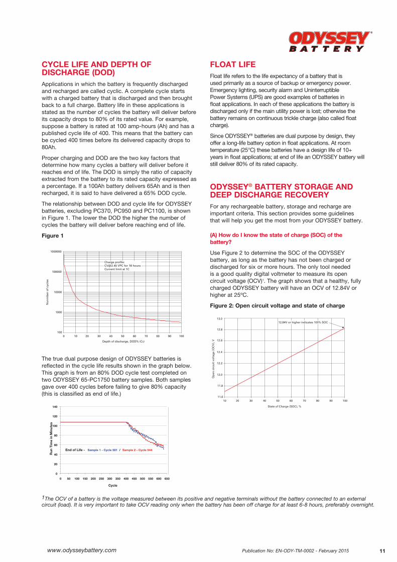
CYCLE LIFE AND DEPTH OF DISCHARGE (DOD)Applications in which the battery is frequently discharged and recharged are called cyclic. A complete cycle starts with a charged battery that is discharged and then brought back to a full charge. Battery life in these applications is stated as the number of cycles the battery will deliver before its capacity drops to 80% of its rated value. For example, suppose a battery is rated at 100 amp-hours (Ah) and has a published cycle life of 400. This means that the battery can be cycled 400 times before its delivered capacity drops to 80Ah.
Proper charging and DOD are the two key factors that determine how many cycles a battery will deliver before it reaches end of life. The DOD is simply the ratio of capacity extracted from the battery to its rated capacity expressed as a percentage. If a 100Ah battery delivers 65Ah and is then recharged, it is said to have delivered a 65% DOD cycle.
The relationship between DOD and cycle life for ODYSSEY batteries, excluding PC370, PC950 and PC1100, is shown in Figure 1. The lower the DOD the higher the number of cycles the battery will deliver before reaching end of life.
Figure 1
The true dual purpose design of ODYSSEY batteries is reflected in the cycle life results shown in the graph below. This graph is from an 80% DOD cycle test completed on two ODYSSEY 65-PC1750 battery samples. Both samples gave over 400 cycles before failing to give 80% capacity (this is classified as end of life.)
FLOAT LIFEFloat life refers to the life expectancy of a battery that is used primarily as a source of backup or emergency power. Emergency lighting, security alarm and Uninterruptible Power Systems (UPS) are good examples of batteries in float applications. In each of these applications the battery is discharged only if the main utility power is lost; otherwise the battery remains on continuous trickle charge (also called float charge).
Since ODYSSEY® batteries are dual purpose by design, they offer a long-life battery option in float applications. At room temperature (25°C) these batteries have a design life of 10+ years in float applications; at end of life an ODYSSEY battery will still deliver 80% of its rated capacity.
ODYSSEY® BATTERY STORAGE AND DEEP DISCHARGE RECOVERY
For any rechargeable battery, storage and recharge are important criteria. This section provides some guidelines that will help you get the most from your ODYSSEY battery.
(A) How do I know the state of charge (SOC) of the battery?
Use Figure 2 to determine the SOC of the ODYSSEY battery, as long as the battery has not been charged or discharged for six or more hours. The only tool needed is a good quality digital voltmeter to measure its open circuit voltage (OCV)1. The graph shows that a healthy, fully charged ODYSSEY battery will have an OCV of 12.84V or higher at 25ºC.
Figure 2: Open circuit voltage and state of charge
1000000
100000
10000
1000
Nu
nm
ber
of
cycl
es
Depth of discharge, DOD% (C5)
1000 10 20 30 40 50 60 70 80 90 100
Charge profile:[email protected] VPC for 16 hoursCurrent limit at 1C
0
20
40
60
80
100
120
140
0 50 100 150 200 250 300 350 400 450 500 550 600 650
Run
Tim
e in
Min
utes
Cycle
End of Life - Sample 1 - Cycle 581 / Sample 2 - Cycle 544
State of Charge (SOC), %
Op
en c
ircu
it v
olt
age
(OC
V),
V
10 20 30 40 50 60 70 80 90 100
13.0
12.8
12.6
12.4
12.2
12.0
11.8
11.6
12.84V or higher indicates 100% SOC
1The OCV of a battery is the voltage measured between its positive and negative terminals without the battery connected to an external circuit (load). It is very important to take OCV reading only when the battery has been off charge for at least 6-8 hours, preferably overnight.
Publication No: EN-ODY-TM-0002 - February 2015www.odysseybattery.com12
(B) How long can the battery be stored?
ODYSSEY batteries should be fully charged prior to storage. Fully charged ODYSSEY batteries can be stored for up to 24 months at 25ºC. Battery voltage naturally decreases with time and with increased temperature. The battery voltage should be checked periodically. If the battery voltage drops to 12.0 volts (35% state of charge) it should be recharged immediately to avoid permanent battery damage. The following can be used as a rough approximation for the potential storage times at different temperatures.
Figure 3: ODYSSEY® battery storage time at temperatures
Storage Temperature (ºC) Storage Time (Months)
5 48
15 36
25 24
35 12
45 6
(C) Can the battery recover from deep discharge conditions?
Yes, the ODYSSEY battery can recover from extremely deep discharges as the following test results demonstrate.
(1) German DIN standard test for overdischarge recovery
In this test, a PC925 was discharged over 20 hours (0.05C10 rate)2. After the discharge2 a 5Ω resistor was placed across the battery terminals and the battery kept in storage for 28 days.
At the end of the storage period, the battery was charged at 13.5V for only 48 hours. A second 0.05C10 discharge yielded 97% of rated capacity, indicating that a low rate 48-hour charge after such a deep discharge was insufficient; however, the intent of the test is to determine if the battery is recoverable from extremely deep discharges using only a standby float charger. A standard automotive charger at 14.4V would have allowed the battery to recover greater than 97% of its capacity.
These test results prove that ODYSSEY batteries can recover from deep discharge conditions. Reinforcing this conclusion is the next test, which is even harsher than the DIN standard test, because in this test the battery was stored in a discharged state at a temperature of 50°C.
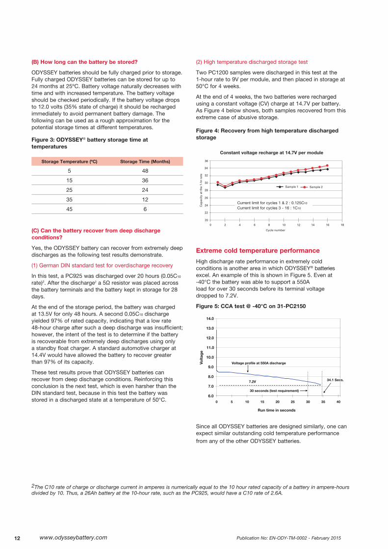
(2) High temperature discharged storage test
Two PC1200 samples were discharged in this test at the 1-hour rate to 9V per module, and then placed in storage at 50°C for 4 weeks.
At the end of 4 weeks, the two batteries were recharged using a constant voltage (CV) charge at 14.7V per battery. As Figure 4 below shows, both samples recovered from this extreme case of abusive storage.
Figure 4: Recovery from high temperature discharged storage
Extreme cold temperature performance
High discharge rate performance in extremely cold conditions is another area in which ODYSSEY® batteries excel. An example of this is shown in Figure 5. Even at -40°C the battery was able to support a 550A load for over 30 seconds before its terminal voltage dropped to 7.2V.
Figure 5: CCA test @ -40°C on 31-PC2150
Since all ODYSSEY batteries are designed similarly, one can expect similar outstanding cold temperature performance from any of the other ODYSSEY batteries.
Cycle number
1086 420 12 14 16 18
36
34
32
30
28
26
24
22
20
Sample 1 Sample 2
Cap
acit
y at
th
e 1-
hr
rate
Constant voltage recharge at 14.7V per module
Current limit for cycles 1 & 2 : 0.125C10
Current limit for cycles 3 - 16 : 1C10
2The C10 rate of charge or discharge current in amperes is numerically equal to the 10 hour rated capacity of a battery in ampere-hours divided by 10. Thus, a 26Ah battery at the 10-hour rate, such as the PC925, would have a C10 rate of 2.6A.
6.0
7.0
8.0
9.0
10.0
11.0
12.0
13.0
14.0
0 5 10 15 20 25 30 35 40
Volt
age
Run time in seconds
Voltage profile at 550A discharge
30 seconds (test requirement)
7.2V 34.1 Secs.
www.odysseybattery.com 13Publication No: EN-ODY-TM-0002 - February 2015
PARASITIC LOADS
With the proliferation of more and more electronic equipment in cars, trucks, motorcycles and powersports equipment, the phenomenon of parasitic loads is becoming a serious problem.
Parasitic loads are small currents, typically of the order of a few milliamps (mA) that the battery has to deliver continuously. Retaining memories and operating security systems are common examples of parasitic drains on batteries in modern systems.
On the surface it would seem that such small loads would not be a factor in the overall scheme of things. However, since parasitic loads can be applied on a long-term basis (weeks or months is not uncommon), the cumulative amp-hours (Ah) extracted from the battery can be significant. For example, a 10mA draw on a motorcycle battery will discharge it by 0.24Ah per day. If left unchecked for 30 days, that small 10mA parasitic load will discharge a 20Ah battery by 7.2Ah – a 36% depth of discharge (DOD).
Regardless of the application, it is important to make sure your battery does not have a parasitic load; if there is a slow drain, connect the battery to a float (trickle) charger that puts out between 13.5V and 13.8V at the battery terminals. Physically disconnecting one of the battery cables is an alternate method to eliminate the drain.
SHOCK, IMPACT AND VIBRATION TESTING (A) Caterpillar™ 100-hour vibration test
In this test, a fully charged battery was vibrated at 34±1 Hz and 0.075" (1.9mm) total amplitude in a vertical direction, corresponding to an acceleration of 4.4g. The test was conducted for a total of 100 hours. The battery is considered to have passed the test if (a) it does not lose any electrolyte, (b) it is able to support a load test and (c) it does not leak when subjected to a pressure test.
The ODYSSEY battery successfully completed this arduous test.
(B) Shock and vibration test per IEC 61373, Sections 8-10
An independent test laboratory tested an ODYSSEY 31-PC2150 battery for compliance to IEC standard 61373, Category 1, Class B, and Sections 8 through 10. Section 8 calls for a functional random vibration test, Section 9 requires a long-life random vibration test and Section 10 is for a shock test. Table 2, in the next column summarizes the test results.
Table 2: Shock and vibration test results per IEC 61373
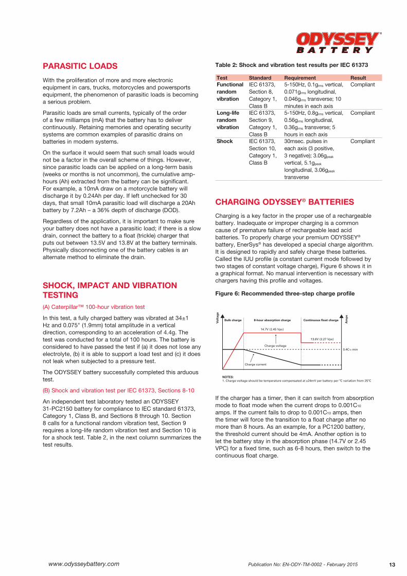
CHARGING ODYSSEY® BATTERIES
Charging is a key factor in the proper use of a rechargeable battery. Inadequate or improper charging is a common cause of premature failure of rechargeable lead acid batteries. To properly charge your premium ODYSSEY® battery, EnerSys® has developed a special charge algorithm. It is designed to rapidly and safely charge these batteries. Called the IUU profile (a constant current mode followed by two stages of constant voltage charge), Figure 6 shows it in a graphical format. No manual intervention is necessary with chargers having this profile and voltages.
Figure 6: Recommended three-step charge profile
If the charger has a timer, then it can switch from absorption mode to float mode when the current drops to 0.001C10 amps. If the current fails to drop to 0.001C10 amps, then the timer will force the transition to a float charge after no more than 8 hours. As an example, for a PC1200 battery, the threshold current should be 4mA. Another option is to let the battery stay in the absorption phase (14.7V or 2.45 VPC) for a fixed time, such as 6-8 hours, then switch to the continuous float charge.
Test Standard Requirement ResultFunctional random vibration
IEC 61373, Section 8, Category 1, Class B
5-150Hz, 0.1grms vertical, 0.071grms longitudinal, 0.046grms transverse; 10 minutes in each axis
Compliant
Long-life random vibration
IEC 61373, Section 9, Category 1, Class B
5-150Hz, 0.8grms vertical, 0.56grms longitudinal, 0.36grms transverse; 5 hours in each axis
Compliant
Shock IEC 61373, Section 10, Category 1, Class B
30msec. pulses in each axis (3 positive, 3 negative); 3.06gpeak vertical, 5.1gpeak longitudinal, 3.06gpeak transverse
Compliant
Bulk charge(RED)
8-hour absorption charge(ORANGE)
Continuous float charge(GREEN)
Charge current
Charge voltage
Bulk charge 8-hour absorption charge Continuous float charge
14.7V (2.45 Vpc)
NOTES:1. Charge voltage should be temperature compensated at ±24mV per battery per ºC variation from 25ºC
Vo
ltag
e
Am
ps
13.6V (2.27 Vpc)
0.4C10 min
Publication No: EN-ODY-TM-0002 - February 2015www.odysseybattery.com14
Table 3 shows the minimum charge currents for the full range of ODYSSEY batteries when they are used in a deep cycling application. When using a charger with the IUU profile, we suggest the following ratings for your ODYSSEY battery. Note the charger current in the bulk charge mode must be 0.4C10 or more.
Table 3: Battery size and minimum three-step charger current
Charger Recommended ODYSSEY® Battery Model* rating, amps
6A PC310 / PC370 / PC535 / PC545 / PC625 / PC680
10A PC925 or smaller battery
15A PC1200 or smaller battery
25A PC1500 or smaller battery
25A PC1700 or smaller battery
40A PC2150 or smaller battery
50A PC2250 or smaller battery
Small, portable automotive and powersport chargers may also be used to charge your ODYSSEY battery. These chargers are generally designed to bring a discharged battery to a state of charge (SOC) that is high enough to crank an engine. Once the engine is successfully cranked, its alternator should fully charge the battery. It is important to keep in mind the design limitations of these small chargers when using them.
Another class of chargers is designed specifically to maintain a battery in a high SOC. These chargers, normally in the 3/4 amp to 11/2 amp range, are not big enough to charge a deeply discharged ODYSSEY® battery. They must only be used either to continuously compensate for parasitic losses or to maintain a trickle charge on a stored battery, as long as the correct voltages are applied. It is very important, therefore, to ensure that the ODYSSEY battery is fully charged before this type of charger is connected to it.
Effect of undercharge in cycling applications
Proper and adequate charging is necessary to ensure that ODYSSEY batteries deliver their full design life. Generally speaking, a full recharge requires about 5% more amp-hours (Ah) must be put back in than was taken out. In other words, for each amp-hour extracted from the battery, about 1.05Ah must be put back to complete the recharge.
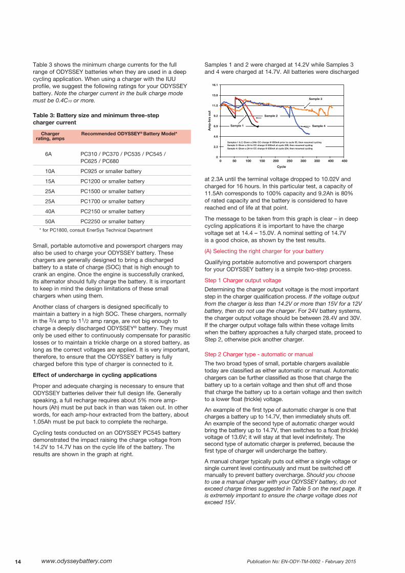
Cycling tests conducted on an ODYSSEY PC545 battery demonstrated the impact raising the charge voltage from 14.2V to 14.7V has on the cycle life of the battery. The results are shown in the graph at right.
Samples 1 and 2 were charged at 14.2V while Samples 3 and 4 were charged at 14.7V. All batteries were discharged
at 2.3A until the terminal voltage dropped to 10.02V and charged for 16 hours. In this particular test, a capacity of 11.5Ah corresponds to 100% capacity and 9.2Ah is 80% of rated capacity and the battery is considered to have reached end of life at that point.
The message to be taken from this graph is clear – in deep cycling applications it is important to have the charge voltage set at 14.4 – 15.0V. A nominal setting of 14.7V is a good choice, as shown by the test results.
(A) Selecting the right charger for your battery
Qualifying portable automotive and powersport chargers for your ODYSSEY battery is a simple two-step process.
Step 1 Charger output voltage
Determining the charger output voltage is the most important step in the charger qualification process. If the voltage output from the charger is less than 14.2V or more than 15V for a 12V battery, then do not use the charger. For 24V battery systems, the charger output voltage should be between 28.4V and 30V. If the charger output voltage falls within these voltage limits when the battery approaches a fully charged state, proceed to Step 2, otherwise pick another charger.
Step 2 Charger type - automatic or manual
The two broad types of small, portable chargers available today are classified as either automatic or manual. Automatic chargers can be further classified as those that charge the battery up to a certain voltage and then shut off and those that charge the battery up to a certain voltage and then switch to a lower float (trickle) voltage.
An example of the first type of automatic charger is one that charges a battery up to 14.7V, then immediately shuts off. An example of the second type of automatic charger would bring the battery up to 14.7V, then switches to a float (trickle) voltage of 13.6V; it will stay at that level indefinitely. The second type of automatic charger is preferred, because the first type of charger will undercharge the battery.
A manual charger typically puts out either a single voltage or single current level continuously and must be switched off manually to prevent battery overcharge. Should you choose to use a manual charger with your ODYSSEY battery, do not exceed charge times suggested in Table 5 on the next page. It is extremely important to ensure the charge voltage does not exceed 15V.
0
2.3
4.6
6.9
9.2
11.5
13.8
16.1
0 50 100 150 200 250 300 350 400 450
Am
p-h
rs o
ut
Cycle
Samples 1 & 2: Given a 24hr CC charge @ 650mA prior to cycle 55, then resumed cycling Sample 3: Given a 24-hr CC charge @ 650mA at cycle 359, then resumed cycling Sample 4: Given a 24-hr CC charge @ 650mA at cycle 254, then resumed cycling
Sample 3
Sample 4 Sample 1
Sample 2
* for PC1800, consult EnerSys Technical Department
www.odysseybattery.com 15Publication No: EN-ODY-TM-0002 - February 2015
(B) Selecting battery type on your charger
Although it is not possible to cover every type of battery charger available today, this section gives the ODYSSEY battery user some general charger usage guidelines to follow, after the charger has been qualified for use with this battery.
In general, do not use either the gel cell or maintenance free setting, if provided on your charger. Choose the deep cycle or AGM option, should there be one on your charger. Table 5 below gives suggested charge times based on charger currents. As previously indicated, deep cycling applications require a minimum 0.4C10 current available from the charger so the values shown in Table 5 do not apply to all products in all applications. To achieve maximum life from your ODYSSEY battery after completing the charge time in Table 5, we recommend that you switch your charger to the trickle charge position and leave the battery connected to the charger for an additional 6-8 hours. The trickle charge voltage should be 13.5V to 13.8V.
Table 5: Suggested charge times (excludes cycling applications)
The charge times recommended in Table 5 assume that the ODYSSEY® battery is fully discharged and these charge times will only achieve about a 80% state of charge. For partially discharged batteries, the charge times should be appropriately reduced. The graph in Figure 2, showing OCV and SOC, must be used to determine the battery’s SOC. The battery should be trickle charged after high rate charging, regardless of its initial SOC.
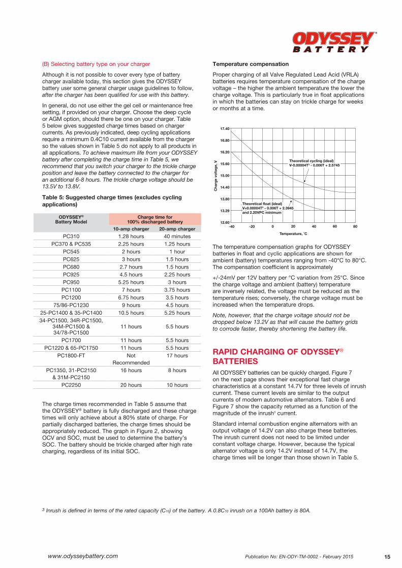
Temperature compensation
Proper charging of all Valve Regulated Lead Acid (VRLA) batteries requires temperature compensation of the charge voltage – the higher the ambient temperature the lower the charge voltage. This is particularly true in float applications in which the batteries can stay on trickle charge for weeks or months at a time.
The temperature compensation graphs for ODYSSEY batteries in float and cyclic applications are shown for ambient (battery) temperatures ranging from -40°C to 80°C. The compensation coefficient is approximately
+/-24mV per 12V battery per °C variation from 25°C. Since the charge voltage and ambient (battery) temperature are inversely related, the voltage must be reduced as the temperature rises; conversely, the charge voltage must be increased when the temperature drops.
Note, however, that the charge voltage should not be dropped below 13.2V as that will cause the battery grids to corrode faster, thereby shortening the battery life.
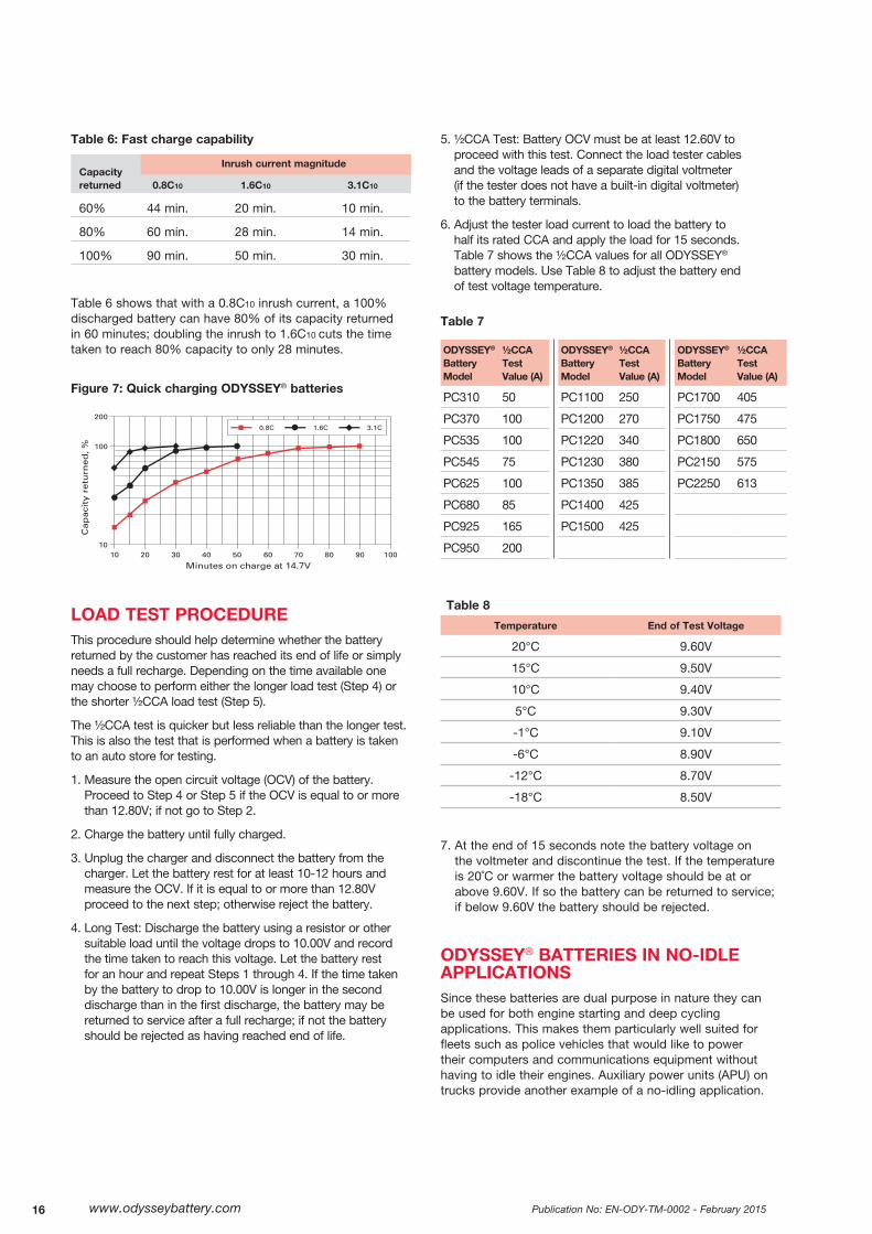
RAPID CHARGING OF ODYSSEY® BATTERIESAll ODYSSEY batteries can be quickly charged. Figure 7 on the next page shows their exceptional fast charge characteristics at a constant 14.7V for three levels of inrush current. These current levels are similar to the output currents of modern automotive alternators. Table 6 and Figure 7 show the capacity returned as a function of the magnitude of the inrush3 current.
Standard internal combustion engine alternators with an output voltage of 14.2V can also charge these batteries. The inrush current does not need to be limited under constant voltage charge. However, because the typical alternator voltage is only 14.2V instead of 14.7V, the charge times will be longer than those shown in Table 5.
ODYSSEY®
Battery ModelCharge time for
100% discharged battery
10-amp charger 20-amp charger
PC310 1.28 hours 40 minutesPC370 & PC535 2.25 hours 1.25 hours
PC545 2 hours 1 hourPC625 3 hours 1.5 hoursPC680 2.7 hours 1.5 hoursPC925 4.5 hours 2.25 hoursPC950 5.25 hours 3 hoursPC1100 7 hours 3.75 hoursPC1200 6.75 hours 3.5 hours
75/86-PC1230 9 hours 4.5 hours25-PC1400 & 35-PC1400 10.5 hours 5.25 hours34-PC1500, 34R-PC1500,
34M-PC1500 & 34/78-PC1500
11 hours 5.5 hours
PC1700 11 hours 5.5 hoursPC1220 & 65-PC1750 11 hours 5.5 hours
PC1800-FT Not Recommended
17 hours
PC1350, 31-PC2150& 31M-PC2150
16 hours 8 hours
PC2250 20 hours 10 hours
Temperature, ˚C
Cha
rge
volt
age,
V
17.40
16.80
16.20
15.60
15.00
14.40
13.80
13.29
12.60
Theoretical cycling (ideal)V-0.00004T3 - 0.006T + 2.5745
Theoretical float (ideal)V=0.00004T3 - 0.006T + 2.3945and 2.20VPC minimum
3 Inrush is defined in terms of the rated capacity (C10) of the battery. A 0.8C10 inrush on a 100Ah battery is 80A.
Publication No: EN-ODY-TM-0002 - February 2015www.odysseybattery.com16
Table 6: Fast charge capability
Capacity
Inrush current magnitude
returned 0.8C10 1.6C10 3.1C10
60% 44 min. 20 min. 10 min.
80% 60 min. 28 min. 14 min.
100% 90 min. 50 min. 30 min.
Table 6 shows that with a 0.8C10 inrush current, a 100% discharged battery can have 80% of its capacity returned in 60 minutes; doubling the inrush to 1.6C10 cuts the time taken to reach 80% capacity to only 28 minutes.
Figure 7: Quick charging ODYSSEY® batteries
LOAD TEST PROCEDUREThis procedure should help determine whether the battery returned by the customer has reached its end of life or simply needs a full recharge. Depending on the time available one may choose to perform either the longer load test (Step 4) or the shorter ½CCA load test (Step 5).
The ½CCA test is quicker but less reliable than the longer test. This is also the test that is performed when a battery is taken to an auto store for testing.
1. Measure the open circuit voltage (OCV) of the battery. Proceed to Step 4 or Step 5 if the OCV is equal to or more than 12.80V; if not go to Step 2.
2. Charge the battery until fully charged.
3. Unplug the charger and disconnect the battery from the charger. Let the battery rest for at least 10-12 hours and measure the OCV. If it is equal to or more than 12.80V proceed to the next step; otherwise reject the battery.
4. Long Test: Discharge the battery using a resistor or other suitable load until the voltage drops to 10.00V and record the time taken to reach this voltage. Let the battery rest for an hour and repeat Steps 1 through 4. If the time taken by the battery to drop to 10.00V is longer in the second discharge than in the first discharge, the battery may be returned to service after a full recharge; if not the battery should be rejected as having reached end of life.
5. ½CCA Test: Battery OCV must be at least 12.60V to proceed with this test. Connect the load tester cables and the voltage leads of a separate digital voltmeter (if the tester does not have a built-in digital voltmeter) to the battery terminals.
6. Adjust the tester load current to load the battery to half its rated CCA and apply the load for 15 seconds. Table 7 shows the ½CCA values for all ODYSSEY® battery models. Use Table 8 to adjust the battery end of test voltage temperature.
Table 7
ODYSSEY® Battery Model
½CCA Test Value (A)
ODYSSEY® Battery Model
½CCA Test Value (A)
ODYSSEY® Battery Model
½CCA Test Value (A)
PC310 50 PC1100 250 PC1700 405
PC370 100 PC1200 270 PC1750 475
PC535 100 PC1220 340 PC1800 650
PC545 75 PC1230 380 PC2150 575
PC625 100 PC1350 385 PC2250 613
PC680 85 PC1400 425
PC925 165 PC1500 425
PC950 200
Table 8
Temperature End of Test Voltage
20°C 9.60V
15°C 9.50V
10°C 9.40V
5°C 9.30V
-1°C 9.10V
-6°C 8.90V
-12°C 8.70V
-18°C 8.50V
7. At the end of 15 seconds note the battery voltage on the voltmeter and discontinue the test. If the temperature is 20˚C or warmer the battery voltage should be at or above 9.60V. If so the battery can be returned to service; if below 9.60V the battery should be rejected.
ODYSSEY® BATTERIES IN NO-IDLE APPLICATIONSSince these batteries are dual purpose in nature they can be used for both engine starting and deep cycling applications. This makes them particularly well suited for fleets such as police vehicles that would like to power their computers and communications equipment without having to idle their engines. Auxiliary power units (APU) on trucks provide another example of a no-idling application.
www.odysseybattery.com 17Publication No: EN-ODY-TM-0002 - February 2015
All of these require energy sources to power loads such as computers and refrigerators with the engines shut off to reduce their carbon footprints and lower fuel consumption.
As discussed in a previous section, properly charged ODYSSEY batteries are capable of delivering as many as 400 cycles to a 80% depth of discharge (DOD). A shallower discharge will yield higher cycles, as noted in the cycle life vs. DOD graph shown earlier. This is the reason why ODYSSEY batteries are becoming increasingly popular in APU and police fleet applications that require batteries to have both high cycling and excellent engine cranking capabilities in the same package.
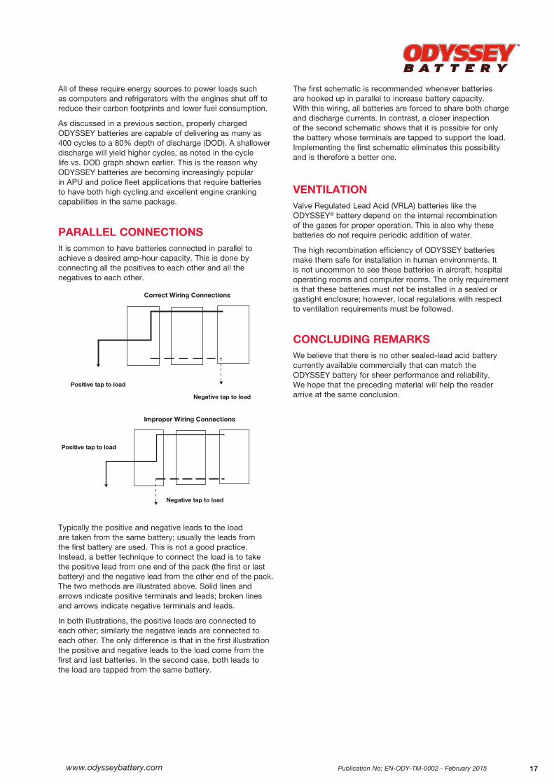
PARALLEL CONNECTIONSIt is common to have batteries connected in parallel to achieve a desired amp-hour capacity. This is done by connecting all the positives to each other and all the negatives to each other.
Typically the positive and negative leads to the load are taken from the same battery; usually the leads from the first battery are used. This is not a good practice. Instead, a better technique to connect the load is to take the positive lead from one end of the pack (the first or last battery) and the negative lead from the other end of the pack. The two methods are illustrated above. Solid lines and arrows indicate positive terminals and leads; broken lines and arrows indicate negative terminals and leads.
In both illustrations, the positive leads are connected to each other; similarly the negative leads are connected to each other. The only difference is that in the first illustration the positive and negative leads to the load come from the first and last batteries. In the second case, both leads to the load are tapped from the same battery.
The first schematic is recommended whenever batteries are hooked up in parallel to increase battery capacity. With this wiring, all batteries are forced to share both charge and discharge currents. In contrast, a closer inspection of the second schematic shows that it is possible for only the battery whose terminals are tapped to support the load. Implementing the first schematic eliminates this possibility and is therefore a better one.
VENTILATION Valve Regulated Lead Acid (VRLA) batteries like the ODYSSEY® battery depend on the internal recombination of the gases for proper operation. This is also why these batteries do not require periodic addition of water.
The high recombination efficiency of ODYSSEY batteries make them safe for installation in human environments. It is not uncommon to see these batteries in aircraft, hospital operating rooms and computer rooms. The only requirement is that these batteries must not be installed in a sealed or gastight enclosure; however, local regulations with respect to ventilation requirements must be followed.
CONCLUDING REMARKSWe believe that there is no other sealed-lead acid battery currently available commercially that can match the ODYSSEY battery for sheer performance and reliability. We hope that the preceding material will help the reader arrive at the same conclusion.
Positive tap to load
Positive tap to load
Negative tap to load
Negative tap to load
Correct Wiring Connections
Improper Wiring Connections
Publication No: EN-ODY-TM-0002 - February 2015www.odysseybattery.com18
FREQUENTLY ASKED SLI BATTERY QUESTIONS
What is the CCA rating?The cold cranking ampere (CCA) rating refers to the number of amperes a battery can deliver for 30 seconds at a temperature of -18°C before the voltage drops to 1.20 volts per cell, or 7.20 volts for a 12V battery. A 12V battery that has a rating of 550 CCA means that the battery will provide 550 amps for 30 seconds at -18°C before the voltage falls to 7.20V.
What is the MCA rating?
The marine cranking ampere (MCA) rating refers to the number of amperes a battery can deliver for 30 seconds at a temperature of 0°C until the battery voltage drops to 7.20 volts for a 12V battery. A 12V battery that has a MCA rating of 725 MCA means that the battery will give 725 amperes for 30 seconds at 0°C before the voltage falls to 7.20V.
The MCA is sometimes called the cranking amperes or CA.
What is a HCA rating?
The abbreviation HCA stands for hot cranking amps. It is the same as MCA, CA or CCA, except that the temperature at which the test is conducted is 27°C.
What is the PHCA rating?
Unlike CCA and MCA the pulse hot cranking amp (PHCA) rating does not have an “official” definition; however, we believe that for true SLI purposes, a 30-second discharge is unrealistic. The PHCA, a short duration (about 3-5 seconds) high rate discharge, is more realistic. Because the discharge is for such a short time, it is more like a pulse.
Are these gel cells?
No, the ODYSSEY® battery is NOT a gel cell. It is an absorbed glass mat (AGM) type battery, meaning there is no free acid inside the battery; all the acid is kept absorbed in the glass mat separators. These separators serve to keep the positive and negative plates apart.
What is the difference between gel cell and AGM?
The key difference between the gel cell and the absorbed glass mat (AGM) is that in the AGM cell all the electrolyte is in the separator, whereas in the gel cell the acid is in the cells in a gel form. If the ODYSSEY battery were to split open, there would be no acid spillage! That is why we call the ODYSSEY battery a Drycell battery.
What is the Ah rating?
The ampere-hour (Ah) rating defines the capacity of a battery. A battery rated at 100Ah at the 10-hour rate of discharge will deliver 10A for 10 hours before the terminal voltage drops to a standard value such as 10.02 volts for a 12V battery. The PC1200 battery, rated at 40Ah will deliver 4A for 10 hours.
What is reserve capacity rating?
The reserve capacity of a battery is the number of minutes it can support a 25-ampere load at 27°C before its voltage drops to 10.50 volts for a 12V battery. A 12V battery with a reserve capacity rating of 100 will deliver 25 amps for 100 minutes at 27°C before its voltage drops to 10.5V.
www.odysseybattery.com 19Publication No: EN-ODY-TM-0002 - February 2015
Is the ODYSSEY® battery a dry battery?
Because the ODYSSEY® battery has no free acid inside, it is exempted from the requirements of 49 CFR § 173.159 of the US Department of Transportation (USDOT). The battery also enjoys a “nonspillable” classification and falls under the International Air Transport Association (IATA) “unrestricted” air shipment category. These batteries may be shipped completely worry-free. Supporting documentation is available.
What is impedance?
The impedance of a battery is a measure of how easily it can be discharged. The lower the impedance the easier it is to discharge the battery. The impedance of the ODYSSEY battery is considerably less than that of a conventional SLI battery, so its high rate discharge capability is significantly higher than that of a conventional SLI battery.
What is the short-circuit current of these batteries?
As mentioned before, this battery has very low impedance, meaning that the short circuit current is very high. For a PC925 battery, the short circuit current can be as high as 2,500 amperes.
Do I ruin the battery if I accidentally drop it?
Not necessarily, but it is possible to damage the internal connections sufficiently to damage the battery.
Does mishandling the battery void the warranty?
Our warranty applies only to manufacturing defects and workmanship issues; the policy does not cover damages suffered due to product mishandling.
What is so special about thin plate pure lead technology? Is it a new technology?
The answer lies in the very high purity (99.99%) of our raw lead materials, making our product very special. The technology is not new; the sealed lead recombinant technology was invented and patented by us back in 1973.
Why don’t you have to winterize your batteries? What’s so special about them?
In general, winterizing refers to a special maintenance procedure conducted on an automotive engine to ensure its reliability during the winter season. The procedure essentially checks the engine’s charging system; in addition, the battery is load tested according to a specific method defined by the Battery Council International (BCI). Although ODYSSEY batteries do not specifically require this test to be conducted on them, the final decision whether or not to conduct this test is left to the user’s discretion.
Are these Ni-Cd batteries? Why doesn’t somebody make these in Ni-Cd? Wouldn’t they charge faster as a Ni-Cd?
No, the ODYSSEY battery is NOT a Ni-Cd battery. It is a valve regulated lead acid (VRLA) battery. In general, Ni-Cd batteries are much more expensive to manufacture and recycle, so they are less cost effective than a lead acid product.
A Ni-Cd battery would charge faster than a conventional lead acid battery; however, the ODYSSEY battery is NOT a conventional battery and its charge characteristics are somewhat similar to nickel cadmium batteries. In fact, with a powerful enough charger, it is possible to bring ODYSSEY batteries to better than 95% state of charge in less than 20 minutes! That is very comparable to the fast charge capabilities of a nickel cadmium product.
About EnerSys®
EnerSys® is a global leader in stored energy solutions for automotive, military, and industrial applications. With manufacturing facilities in 18 countries, sales and service locations throughout the world, and over 100 years of battery experience, EnerSys is a powerful partner for automotive service and parts providers.
EnerSys2366 Bernville RoadReading, PA 19605Tel: +1-610-208-1991+1-800-538-3627
EnerSys EMEA EH Europe GmbH Löwenstrasse 328001 Zürich, SwitzerlandTel: +41 (0) 44 215 74 10
EnerSys Asia152 Beach RoadGateway East Building #11-03Singapore 189721Tel: +65 6508 1780
www.odysseybattery.com
© 2015 EnerSys. All rights reserved. Trademarks and logos are the property of EnerSys and its affiliates, except Caterpillar™, which is not the property of EnerSys.
Publication No: EN-ODY-TM-0002 – February 2015 Subject to revisions without prior notice. E.&O.E.