Embed Size (px)
Citation preview
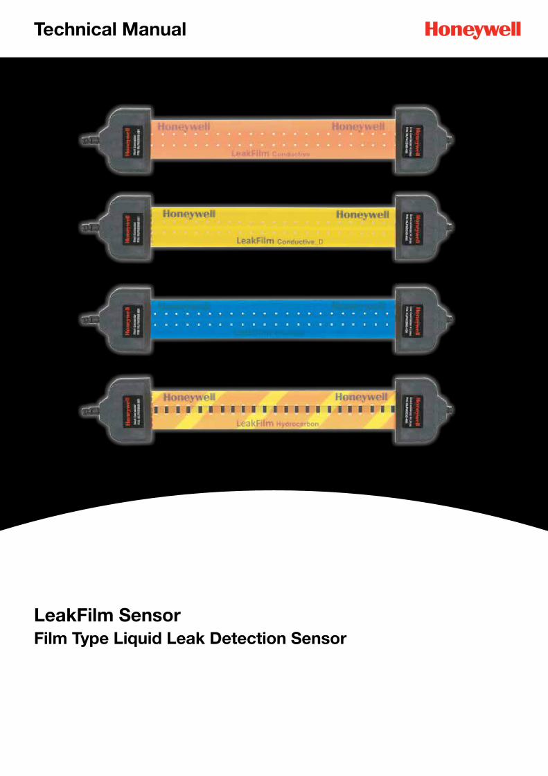
LeakFilm SensorFilm Type Liquid Leak Detection Sensor
Technical Manual
2
LeakFilm Sensor Technical Manual 3013M5006 Issue 1 MAN0969 04-14
Ensure that this Operating Manual is read and understood BEFORE installing / operating / maintaining the equipment. Pay particular attention to Warnings and Cautions. All document Warnings are listed here and repeated where appropriate at the start of the relevant chapter(s) of this Operating Manual. Cautions appear in the sections/sub-sections of the document where they apply.
WARNINGSLeakFilm controllers and sensors are designed for installation and use in ordinary areas only. Do not install the controllers and the sensors in hazardous areas.
Installation must be in accordance with the recognised standards of the appropriate authority in the country concerned.
Access to the terminal block for wiring and switches for configuration of the controller, when carrying out any work, must only be conducted by trained personnel.
Before carrying out any work ensure local regulations and site procedures are followed. Appropriate standards must be followed to maintain the overall certifications.
Never attempt to open a plastic enclosure or connector or replace/refit the wire of the sensor while power is still applied to the controller.
LeakFilm controllers must be earthed/grounded for electrical safety and to limit the effects of radio frequency interference. Earth/ground points are provided “F.G.” or “SHIELD” terminal of the controllers.
Ensure that all screens/instrument earth/clean earth wiring is earthed/grounded at a single point (either at the controller or master controller - BUT NOT BOTH) to prevent false readings or alarms that may occur due to potential earth/ground loops.
The plastic enclosure of the controllers is a potential electrostatic charging hazard. Avoid any conditions that could result in the controllers becoming electrostatically charged.
Take care when handling LeakFilm sensors as they may be damaged by sharp tools.
LeakFilm controllers should be handled with care to avoid mechanical shock and impact.
Do not expose to temperatures, humidity and other conditions beyond the storage and operating ranges.
LeakFilm controllers must have a suitably rated fuse.
LeakFilm controllers and sensors should be installed in a location free from dust, direct sunlight, temperature extreme, strong magnetic field and heavy vibration.
1. Safety

3
LeakFilm Sensor Technical Manual 3013M5006 Issue 1 MAN0969 04-14
2. InformationThis manual is for use with LeakFilm Sensors and Controllers range only.
Honeywell Analytics can take no responsibility for installation and/or use of its equipment if not done so in accordance with the appropriate issue and/or amendment of the Technical Manual.
The reader of this Operating Manual should ensure that it is appropriate in all details for the exact equipment to be installed and/or operated. If in doubt, contact Honeywell Analytics for advice.
The following types of notices are used throughout this Operating Manual:
WARNINGIdentifies a hazardous or unsafe practice which could result in severe injury or
death to personnel.
Caution: Identifies a hazardous or unsafe practice which could result in minor injury to personnel, or product or property damage.
Note: Identifies useful/additional information.
Every effort has been made to ensure the accuracy of this document, however, Honeywell Analytics can assume no responsibility for any errors or omissions in this document or their consequences.
Honeywell Analytics would greatly appreciate being informed of any errors or omissions that may be found in the content of this document.
For information not covered in this document, or if there is a requirement to send comments/corrections about this document, please contact Honeywell Analytics using the contact details given on the back page.
Honeywell Analytics reserve the right to change or revise the information supplied in this document without notice and without obligation to notify any person or organisation of such revision or change. If information is required that does not appear in this document, contact the local distributor/agent or Honeywell Analytics.
4
LeakFilm Sensor Technical Manual 3013M5006 Issue 1 MAN0969 04-14
3. Table of Contents
1 Safety 2
2 Information 3
3 Table of contents 4
4 Introduction 5
4.1 Sensor Types 6
4.2 Sensor Dimension 7
5 Application 8
6 Installation 9
6.1 Location 10
6.2 Sensor installation 10
6.3 Connector assembly 10
6.4 Maintenance 10
6.5 Contact plane of LeakFilm Hydrocarbon 12
7 Characteristic and specification 13
8 Ordering Information 15
9 Warranty statement 16
10 Sensor Installation Drawing 17

5
LeakFilm Sensor Technical Manual 3013M5006 Issue 1 MAN0969 04-14
4. IntroductionThe LeakFilm sensor is a film type sensor that detects liquid leaks. LeakFilm sensors can be installed with various kinds of LeakFilm controllers, so that the leak signal detected by the sensor can be transmitted to the controller immediately to alert users. Depending on the controller type, it is possible to measure the distance between the leak point and the controller.
Advanced TechnologyLeakFilm sensor has advanced and unique film type sensing technology based on conductive polymer and PET, which can provide versatile benefits to customers as listed below:
Fast response timeThe LeakFilm sensor provides a faster response time than cable type sensors.
Easy to maintainThe LeakFilm sensor can be reused again immediately after removing the leakage. Drying time is much shorter than a cable type sensor.
Easy to installThe LeakFilm sensor itself is <400µm thick, and the overall thickness including the adhesive tape is much thinner than a cable type sensor. LeakFilm sensor’s design and technology allows customers to have flexible installation options for pipes, pipe junctions, building basements, inside equipment, facilities, server rooms, etc.
Free to adjust the length of LeakFilmThe LeakFilm sensor can be cut anywhere along the film strip and re-connected again.
SensitivityThe LeakFilm sensor responds to a small amount of liquid while a cable type sensor requires a larger amount of liquid. The sensor can respond to only 0.8mm height of liquid.
Resistance to False AlarmThe LeakFilm sensor can withstand accidental compression (being stepped on or having objects placed on top of the film) without triggering costly false alarms that suspend production and divert resources.

6
LeakFilm Sensor Technical Manual 3013M5006 Issue 1 MAN0969 04-14
4. Introduction
4.1 Sensor Types
There are 4 kinds of sensor types in the LeakFilm sensor range, as shown in the below table. Each sensor can be classified by target liquid and whether it is capable of distance detection.
Product name Target Liquid Features Controller
LeakFilm Conductive
Water and Conductive Liquid
Orange Indoor onlyReusable
LeakFilm MiniLeakFilm 5
LeakFilm Conductive_D
Water and Conductive Liquid
YellowDistance detectionIndoor onlyReusable
LeakFilm Pro
LeakFilm Chemical Chemical
BlueDistance detectionIndoor onlyIrreversible
LeakFilm Pro
LeakFilm Hydrocarbon Hydrocarbon
Orange & YellowOil detectionIndoor onlyIrreversible
LeakFilm HC
Table 1: Sensor types

7
LeakFilm Sensor Technical Manual 3013M5006 Issue 1 MAN0969 04-14
4. Introduction
4.2 Sensor Dimension
All 4 types of sensor have the same external dimensions as shown in the below picture.
LeakFilm Conductive
36 8mm
2 2 4 4 43.43
2 2 4 4 43.43
2 5 5
4.5 5 5
Sensing Hole Ø1.4Guard Film
Guard Film
Guard Film
Guard Film
Circuit Line
Circuit Line
Circuit Line
Circuit Line Conductive PE
Base Film
Base Film
Base Film
Base Film
47 28mm
28mm
28mm
28mm
LeakFilm Conductive_D
LeakFilm Chemical
LeakFilm Hydrocarbon

8
LeakFilm Sensor Technical Manual 3013M5006 Issue 1 MAN0969 04-14
5. Application
Diagram 2: Typical example of LeakFilm installation
LeakFilm is suitable for below applications;
• Data center and server room• Communication facilities and network room• Library• Museum and heritage site• Archive storage• Aquarium• Control room• Utility room• Semiconductor Fab / LED Fab• Chemical process• Tanks• Pipe Lines and Pipe Junctions• Refineries• The areas where potential liquid leak is most likely to be present
9
LeakFilm Sensor Technical Manual 3013M5006 Issue 1 MAN0969 04-14
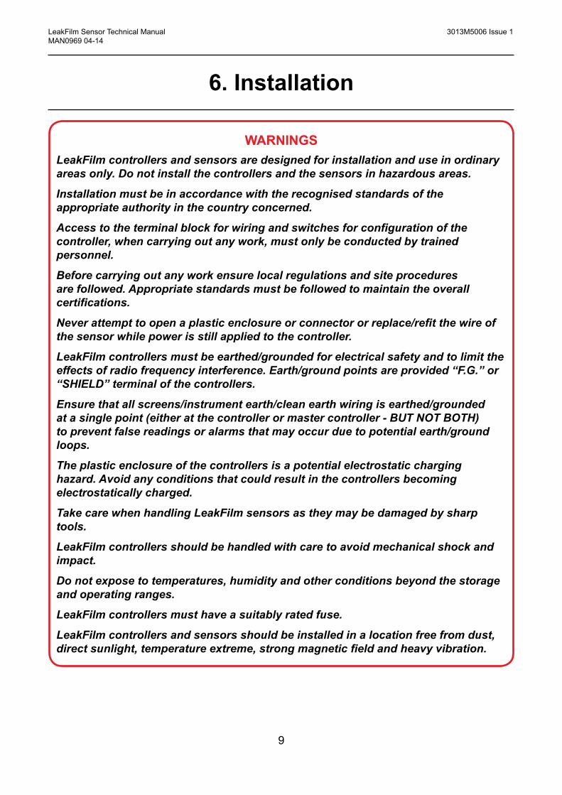
6. Installation
WARNINGSLeakFilm controllers and sensors are designed for installation and use in ordinary areas only. Do not install the controllers and the sensors in hazardous areas.
Installation must be in accordance with the recognised standards of the appropriate authority in the country concerned.
Access to the terminal block for wiring and switches for configuration of the controller, when carrying out any work, must only be conducted by trained personnel.
Before carrying out any work ensure local regulations and site procedures are followed. Appropriate standards must be followed to maintain the overall certifications.
Never attempt to open a plastic enclosure or connector or replace/refit the wire of the sensor while power is still applied to the controller.
LeakFilm controllers must be earthed/grounded for electrical safety and to limit the effects of radio frequency interference. Earth/ground points are provided “F.G.” or “SHIELD” terminal of the controllers.
Ensure that all screens/instrument earth/clean earth wiring is earthed/grounded at a single point (either at the controller or master controller - BUT NOT BOTH) to prevent false readings or alarms that may occur due to potential earth/ground loops.
The plastic enclosure of the controllers is a potential electrostatic charging hazard. Avoid any conditions that could result in the controllers becoming electrostatically charged.
Take care when handling LeakFilm sensors as they may be damaged by sharp tools.
LeakFilm controllers should be handled with care to avoid mechanical shock and impact.
Do not expose to temperatures, humidity and other conditions beyond the storage and operating ranges.
LeakFilm controllers must have a suitably rated fuse.
LeakFilm controllers and sensors should be installed in a location free from dust, direct sunlight, temperature extreme, strong magnetic field and heavy vibration.

10
LeakFilm Sensor Technical Manual 3013M5006 Issue 1 MAN0969 04-14
6. Installation
6.1 Location
The LeakFilm sensor should be installed where a potential liquid leak is most likely to be present. The following points should be noted when locating the sensors.
• When locating the sensors consider the possible damage caused by natural events e.g. rain or flooding.
• Consider ease of access to the sensor for repair and maintenance.
• The sensor and lead cable should not run across any passageways, to avoid abrasion and damage.
6.2 Sensor installation
LeakFilm sensor has double sided tape to adhere to the floor or a flat surface. The following points should be noted when installing the sensors.
• The surface should be clean for better adherence to the sensor.
• Glue or adhesive can be used in addition to standard double sided tape if the surface is not flat or not suitable for double sided tape.
6.3 Connector assembly
LeakFilm provides 4 different types of connectors which are suitable for various installation environments. LeakFilm connectors were designed to be assembled by snapping, so that only a screw driver is required for assembly.
6.4 Maintenance
LeakFilm Conductive and Conductive_D are reusable. Once you wipe out the water from the sensor, it returns to normal immediately. However LeakFilm Chemical and Hydrocarbon are irreversible. Once the liquid has been in contact with the sensor, the part of the sensor wet by the liquid must be replaced or cut. There are 3 options to repair the sensor.
• Replace the wet section with new sensor by using jump connectors. This option works well if the wet point is towards the middle of the sensor.
• Remove or cut the wet section and reassemble the start connector or end connector. This option works well if the wet point is towards the start or end point of the sensor.
• Replace a whole section (connector to connector) of the sensor. This option works well if the above two cases are not applicable.

11
LeakFilm Sensor Technical Manual 3013M5006 Issue 1 MAN0969 04-14
6. Installation
(1) Connector + Sensor Assembly
Circuit Line
Attach circuit line of film sensor horizontally to the contact of connector. (Assemble after placing the bottom cover of sensor upward and then connecting to sensor)
(2) Cover Assembly
Close the bottom cover of the connector and push firmly.
(4) Completion
Turn the sensor and connector around so that the front of sensor can be seen.
(3) Bolt Assembly
Fasten the two screws at the bottom side.
Diagram 3: Connector assembly procedure

12
LeakFilm Sensor Technical Manual 3013M5006 Issue 1 MAN0969 04-14
6. Installation
6.5 Contact plane of LeakFilm Hydrocarbon
When assembling the connectors with the LeakFilm Hydrocarbon sensor, special care should be taken because the connector pins may be not well aligned with the electrode (Conductive PE in Diagram 1) of the sensor from time to time. In order to prevent the misalignment, LeakFilm Hydrocarbon provides a contact plane at the back side of the sensor every 0.5m as shown in the picture. It is strongly recommended that the connectors assembled with LeakFilm Hydrocarbon should use this plane.
Contact plane Conductive PE
Diagram 4: Contact plane of LeakFilm Hydrocarbon
13
LeakFilm Sensor Technical Manual 3013M5006 Issue 1 MAN0969 04-14
7. Characteristics and specifications
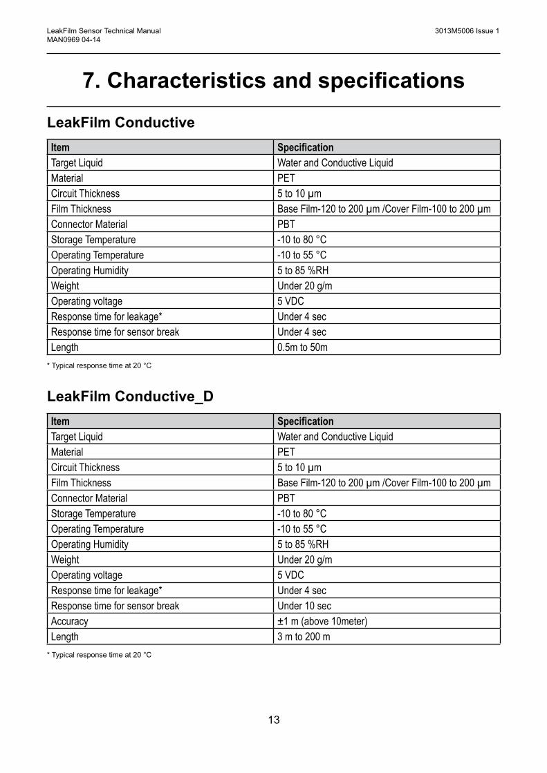
LeakFilm ConductiveItem SpecificationTarget Liquid Water and Conductive LiquidMaterial PETCircuit Thickness 5 to 10 µmFilm Thickness Base Film-120 to 200 µm /Cover Film-100 to 200 µmConnector Material PBTStorage Temperature -10 to 80 °COperating Temperature -10 to 55 °COperating Humidity 5 to 85 %RHWeight Under 20 g/mOperating voltage 5 VDCResponse time for leakage* Under 4 secResponse time for sensor break Under 4 secLength 0.5m to 50m
* Typical response time at 20 °C
LeakFilm Conductive_DItem SpecificationTarget Liquid Water and Conductive LiquidMaterial PETCircuit Thickness 5 to 10 µmFilm Thickness Base Film-120 to 200 µm /Cover Film-100 to 200 µmConnector Material PBTStorage Temperature -10 to 80 °COperating Temperature -10 to 55 °COperating Humidity 5 to 85 %RHWeight Under 20 g/mOperating voltage 5 VDCResponse time for leakage* Under 4 secResponse time for sensor break Under 10 secAccuracy ±1 m (above 10meter)Length 3 m to 200 m
* Typical response time at 20 °C
14
LeakFilm Sensor Technical Manual 3013M5006 Issue 1 MAN0969 04-14
7. Characteristics and specifications
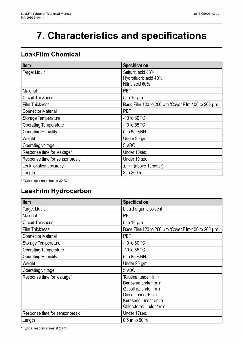
LeakFilm ChemicalItem SpecificationTarget Liquid Sulfuric acid 88%
Hydrofluoric acid 40%Nitric acid 60%
Material PETCircuit Thickness 5 to 10 µmFilm Thickness Base Film-120 to 200 µm /Cover Film-100 to 200 µmConnector Material PBTStorage Temperature -10 to 80 °COperating Temperature -10 to 55 °COperating Humidity 5 to 85 %RHWeight Under 20 g/mOperating voltage 5 VDCResponse time for leakage* Under 10sec.Response time for sensor break Under 10 secLeak location accuracy ±1 m (above 10meter)Length 3 to 200 m
* Typical response time at 20 °C
LeakFilm HydrocarbonItem SpecificationTarget Liquid Liquid organic solventMaterial PETCircuit Thickness 5 to 10 µmFilm Thickness Base Film-120 to 200 µm /Cover Film-100 to 200 µmConnector Material PBTStorage Temperature -10 to 60 °COperating Temperature -10 to 55 °COperating Humidity 5 to 85 %RHWeight Under 20 g/mOperating voltage 5 VDCResponse time for leakage* Toluene: under 1min
Benzene: under 1minGasoline: under 1minDiesel: under 5minKerosene: under 5minChloroform: under 1min
Response time for sensor break Under 17sec.Length 0.5 m to 50 m
* Typical response time at 20 °C
15
LeakFilm Sensor Technical Manual 3013M5006 Issue 1 MAN0969 04-14
8. Ordering Information
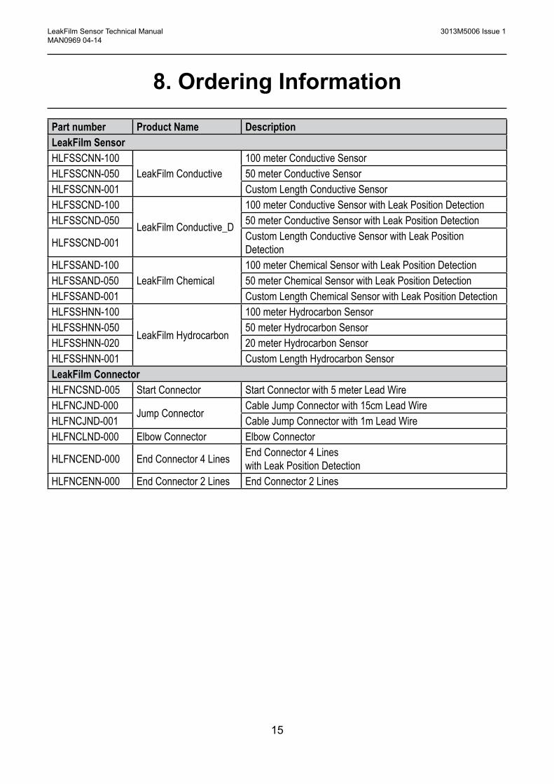
Part number Product Name DescriptionLeakFilm SensorHLFSSCNN-100
LeakFilm Conductive100 meter Conductive Sensor
HLFSSCNN-050 50 meter Conductive SensorHLFSSCNN-001 Custom Length Conductive SensorHLFSSCND-100
LeakFilm Conductive_D
100 meter Conductive Sensor with Leak Position DetectionHLFSSCND-050 50 meter Conductive Sensor with Leak Position Detection
HLFSSCND-001 Custom Length Conductive Sensor with Leak Position Detection
HLFSSAND-100LeakFilm Chemical
100 meter Chemical Sensor with Leak Position DetectionHLFSSAND-050 50 meter Chemical Sensor with Leak Position DetectionHLFSSAND-001 Custom Length Chemical Sensor with Leak Position DetectionHLFSSHNN-100
LeakFilm Hydrocarbon
100 meter Hydrocarbon SensorHLFSSHNN-050 50 meter Hydrocarbon SensorHLFSSHNN-020 20 meter Hydrocarbon SensorHLFSSHNN-001 Custom Length Hydrocarbon SensorLeakFilm ConnectorHLFNCSND-005 Start Connector Start Connector with 5 meter Lead WireHLFNCJND-000
Jump ConnectorCable Jump Connector with 15cm Lead Wire
HLFNCJND-001 Cable Jump Connector with 1m Lead WireHLFNCLND-000 Elbow Connector Elbow Connector
HLFNCEND-000 End Connector 4 Lines End Connector 4 Lines with Leak Position Detection
HLFNCENN-000 End Connector 2 Lines End Connector 2 Lines

16
LeakFilm Sensor Technical Manual 3013M5006 Issue 1 MAN0969 04-14
9. Warranty StatementAll products are designed and manufactured to the latest internationally recognised standards by Honeywell Analytics under a Quality Management system that is certified to ISO 9001. As such Honeywell Analytics warrants its products against defective parts and workmanship and will repair or (at its option) replace any instruments which are or may become defective under proper use within 18 months from date of commissioning by an approved Honeywell Analytics representative or 24 months from date of shipment from Honeywell Analytics, whichever is the sooner. This warranty does not cover disposable batteries or damage caused by accident, abuse, abnormal operating conditions or poisoning of sensor.
Defective goods must be returned to Honeywell Analytics premises accompanied by a detailed description of any issue. Where return of goods is not practicable Honeywell Analytics reserves the right to charge for any site attendance where any fault is not found with the equipment. Honeywell Analytics shall not be liable for any loss or damage whatsoever or howsoever occasioned which may be a direct or indirect result of the use or operation of the Contract Goods by the Buyer or any Party.
This warranty covers instrument and parts sold to the Buyer only by authorised distributors, dealers and representatives as appointed by Honeywell Analytics. The warranties set out in this clause are not pro rata, i.e. the initial warranty period is not extended by virtue of any works carried out there under.
In no event will Honeywell Analytics be liable for any incidental damages, consequential damages, special damages, punitive damages, statutory damages, indirect damages, loss of profits, loss of revenues, or loss of use, even if informed of the possibility of such damages. Honeywell Analytic's liability for any claims arising out of or related to this product will in no case exceed the order value. To the extent permitted by applicable law, these limitations and exclusions will apply regardless of whether liability arises from breach of contract, warranty, tort (including but not limited to negligence), by operation of law, or otherwise.

17
LeakFilm Sensor Technical Manual 3013M5006 Issue 1 MAN0969 04-14
10. Sensor Installation Drawing

18
LeakFilm Sensor Technical Manual 3013M5006 Issue 1 MAN0969 04-14
10. Installation Drawing

Thank you for reading this data sheet.
For pricing or for further information, please contact us at our UK Office, using the details below.
UK OfficeKeison Products,
P.O. Box 2124, Chelmsford, Essex, CM1 3UP, England.Tel: +44 (0)330 088 0560Fax: +44 (0)1245 808399
Email: [email protected]
Please note - Product designs and specifications are subject to change without notice. The user is responsible for determining the suitability of this product.