Embed Size (px)
Citation preview
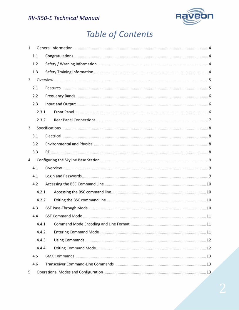
RV-R50-E
Skyline ISM-NA Wireless Base Station
Technical Manual Revision A2 (June 2016)
Raveon Technologies Corporation www.raveon.com | www.ravtrack.com | iot.raveon.com
RV-R50-E Technical Manual
2
Table of Contents
1 General Information ............................................................................................................................. 4
1.1 Congratulations ............................................................................................................................. 4
1.2 Safety / Warning Information ....................................................................................................... 4
1.3 Safety Training Information .......................................................................................................... 4
2 Overview ............................................................................................................................................... 5
2.1 Features ........................................................................................................................................ 5
2.2 Frequency Bands ........................................................................................................................... 6
2.3 Input and Output .......................................................................................................................... 6
2.3.1 Front Panel ............................................................................................................................ 6
2.3.2 Rear Panel Connections ........................................................................................................ 7
3 Specifications ........................................................................................................................................ 8
3.1 Electrical ........................................................................................................................................ 8
3.2 Environmental and Physical .......................................................................................................... 8
3.3 RF .................................................................................................................................................. 8
4 Configuring the Skyline Base Station .................................................................................................... 9
4.1 Overview ....................................................................................................................................... 9
4.1 Login and Passwords ..................................................................................................................... 9
4.2 Accessing the BSC Command Line .............................................................................................. 10
4.2.1 Accessing the BSC command line ........................................................................................ 10
4.2.2 Exiting the BSC command line ............................................................................................ 10
4.3 BST Pass-Through Mode ............................................................................................................. 10
4.4 BST Command Mode .................................................................................................................. 11
4.4.1 Command Mode Encoding and Line Format ...................................................................... 11
4.4.2 Entering Command Mode ................................................................................................... 11
4.4.3 Using Commands ................................................................................................................ 12
4.4.4 Exiting Command Mode ...................................................................................................... 12
4.5 BMX Commands .......................................................................................................................... 13
4.6 Transceiver Command-Line Commands ..................................................................................... 13
5 Operational Modes and Configuration ............................................................................................... 13
RV-R50-E Technical Manual
3
5.1 Modes ......................................................................................................................................... 13
5.1.1 LoRaLite ............................................................................................................................... 13
5.1.2 Dart ..................................................................................................................................... 13
5.1.3 LoRaWAN ............................................................................................................................ 14
5.2 Channel Center Frequency .......................................................................................................... 14
5.3 Channel Bandwidth and Transmit Power ................................................................................... 15
5.3.1 Channel Data Rate............................................................................................................... 15
5.3.2 Channel Occupancy ............................................................................................................. 15
5.4 Data Transmission ....................................................................................................................... 16
5.5 Data Reception ............................................................................................................................ 16
5.5.2 GPS Position and Status ......................................................... Error! Bookmark not defined.
5.6 Device Addressing ....................................................................................................................... 16
5.6.1 ID Addressing Basics ............................................................................................................ 16
6 Diagnostic Provisions ............................................................................. Error! Bookmark not defined.
6.1 Status and Statistics Commands ................................................................................................. 18
7 Troubleshooting .................................................................................................................................. 18
7.1 Symptom: Unit will not receive .................................................................................................. 18
7.2 Symptom: Receive light blinks, but no data is received ............................................................ 19
7.3 Symptom: Long delay before transmitting ................................................................................ 19
8 Mechanical .......................................................................................................................................... 19
8.1 Dimensions .................................................................................................................................. 19
8.2 Mounting ..................................................................................................................................... 19
9 NOTICE ................................................................................................................................................ 20
9.1 Safety Training information ........................................................................................................ 20
10 FCC Compliance Information .......................................................................................................... 20
11 Warranty ......................................................................................................................................... 21
RV-R50-E Technical Manual
4
1 General Information
1.1 Congratulations
Congratulations on your purchase of an Industrial Skyline Base Station. Please take a few minutes to
read this manual carefully. The information presented here will allow you to derive maximum
performance from your radio modem base station. After reading it, keep the manual handy for quick
reference, in case questions arise later on.
1.2 Safety / Warning Information
Blasting Caps and Blasting Areas
To avoid possible interference with blasting operations, turn off this device when you are near electrical
blasting caps, in a blasting area, or in areas posted: “Turn off two-way radio.” Obey all signs and
instructions.
Potentially Explosive Atmospheres
Turn off your radio prior to entering any area with a potentially explosive atmosphere. Do not install this
product for use in areas with potentially explosive atmospheres. Sparks in a potentially explosive
atmosphere can cause an explosion or fire resulting in bodily injury or even death.
Note: The areas with potentially explosive atmospheres referred to above include fueling areas such as
below decks on boats, fuel or chemical transfer or storage facilities, areas where the air contains
chemicals or particles, such as grain, dust or metal powders, and any other area where you would
normally be advised to turn off your vehicle engine. Areas with potentially explosive atmospheres are
often but not always posted.
1.3 Safety Training Information
This radio is restricted to occupational use. Work related operations are permitted only when the radio
operator has the knowledge to control the exposure conditions of its passengers and bystanders by
maintaining the minimum separation distance. Failure to observe these restrictions may result in
exceeding the regulatory exposure limits.
RV-R50-E Technical Manual
5
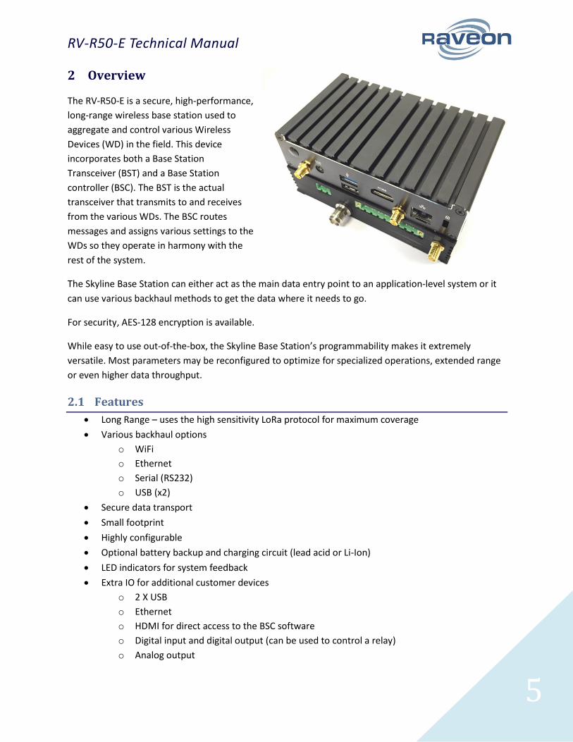
2 Overview
The RV-R50-E is a secure, high-performance,
long-range wireless base station used to
aggregate and control various Wireless
Devices (WD) in the field. This device
incorporates both a Base Station
Transceiver (BST) and a Base Station
controller (BSC). The BST is the actual
transceiver that transmits to and receives
from the various WDs. The BSC routes
messages and assigns various settings to the
WDs so they operate in harmony with the
rest of the system.
The Skyline Base Station can either act as the main data entry point to an application-level system or it
can use various backhaul methods to get the data where it needs to go.
For security, AES-128 encryption is available.
While easy to use out-of-the-box, the Skyline Base Station’s programmability makes it extremely
versatile. Most parameters may be reconfigured to optimize for specialized operations, extended range
or even higher data throughput.
2.1 Features
Long Range – uses the high sensitivity LoRa protocol for maximum coverage
Various backhaul options
o WiFi
o Ethernet
o Serial (RS232)
o USB (x2)
Secure data transport
Small footprint
Highly configurable
Optional battery backup and charging circuit (lead acid or Li-Ion)
LED indicators for system feedback
Extra IO for additional customer devices
o 2 X USB
o Ethernet
o HDMI for direct access to the BSC software
o Digital input and digital output (can be used to control a relay)
o Analog output
RV-R50-E Technical Manual
6
2.2 Frequency Bands
-E: 902 MHz – 928 MHz
2.3 Input and Output
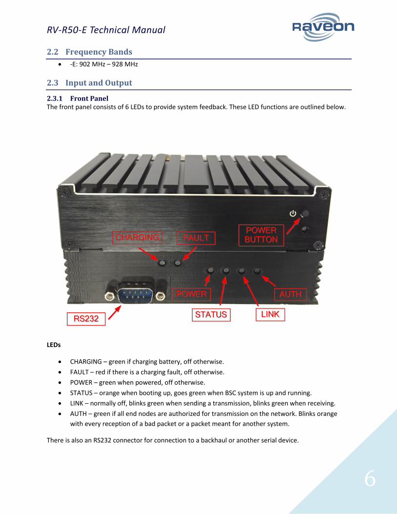
2.3.1 Front Panel The front panel consists of 6 LEDs to provide system feedback. These LED functions are outlined below.
LEDs
CHARGING – green if charging battery, off otherwise.
FAULT – red if there is a charging fault, off otherwise.
POWER – green when powered, off otherwise.
STATUS – orange when booting up, goes green when BSC system is up and running.
LINK – normally off, blinks green when sending a transmission, blinks green when receiving.
AUTH – green if all end nodes are authorized for transmission on the network. Blinks orange
with every reception of a bad packet or a packet meant for another system.
There is also an RS232 connector for connection to a backhaul or another serial device.
RV-R50-E Technical Manual
7
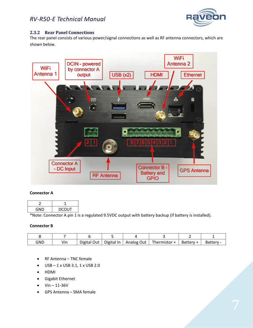
2.3.2 Rear Panel Connections The rear panel consists of various power/signal connections as well as RF antenna connectors, which are
shown below.
Connector A
2 1
GND DCOUT
*Note: Connector A pin 1 is a regulated 9.5VDC output with battery backup (if battery is installed).
Connector B
8 7 6 5 4 3 2 1
GND Vin Digital Out Digital In Analog Out Thermistor + Battery + Battery -
RF Antenna – TNC female
USB – 1 x USB 3.1, 1 x USB 2.0
HDMI
Gigabit Ethernet
Vin – 11-36V
GPS Antenna – SMA female
RV-R50-E Technical Manual
8
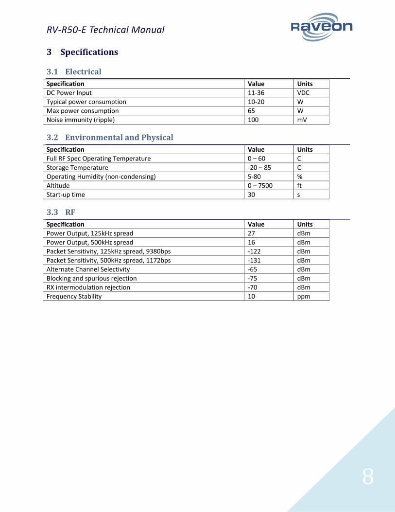
3 Specifications
3.1 Electrical
Specification Value Units
DC Power Input 11-36 VDC
Typical power consumption 10-20 W
Max power consumption 65 W
Noise immunity (ripple) 100 mV
3.2 Environmental and Physical
Specification Value Units
Full RF Spec Operating Temperature 0 – 60 C
Storage Temperature -20 – 85 C
Operating Humidity (non-condensing) 5-80 %
Altitude 0 – 7500 ft
Start-up time 30 s
3.3 RF
Specification Value Units
Power Output, 125kHz spread 27 dBm
Power Output, 500kHz spread 16 dBm
Packet Sensitivity, 125kHz spread, 9380bps -122 dBm
Packet Sensitivity, 500kHz spread, 1172bps -131 dBm
Alternate Channel Selectivity -65 dBm
Blocking and spurious rejection -75 dBm
RX intermodulation rejection -70 dBm
Frequency Stability 10 ppm
RV-R50-E Technical Manual
9
4 Configuring the Skyline Base Station
4.1 Overview
The BSC can be configured in multiple ways:
Through the master gateway (preferred)
SSH (using Putty or a similar program)
o by connecting a PC and the Skyline to an Ethernet switch and creating a local network
o by WiFi if this optional hardware is added at purchase
By connecting an HDMI cable and keyboard to the ports on the rear of the Skyline
Using either of these methods will bring up the command line interface of the Linux computer running
the BSC. From there, the BSC command line can be accessed as described below in the section titles
“Accessing the BSC Command Line”.
From the BSC command line, it is then possible to access the actual hardware radio modem (BST)
command line as described in the section “BST Pass-Through Mode”.
Once connected to the BST, the incoming data will be seen on the screen as it is received. In all Raveon
radios, there is a “Command Mode” where certain registers and features of the radio can be queried
and set. This operation is explained below in the section “BST Command Mode”.
The modem also supports Raveon’s Wireless Modem Exchange (WMX) protocol for commanding and
messaging. WMX is ideal for fully automated control and tighter integration. For more information, see
the WMX Protocol Description document and the Raveon Tech Note “Rapid Radio Configuration using
WMX”.
WARNING: as shown above, there are multiple levels of access provided by this system. Be very careful
to properly end each session as you back out of the various layers.
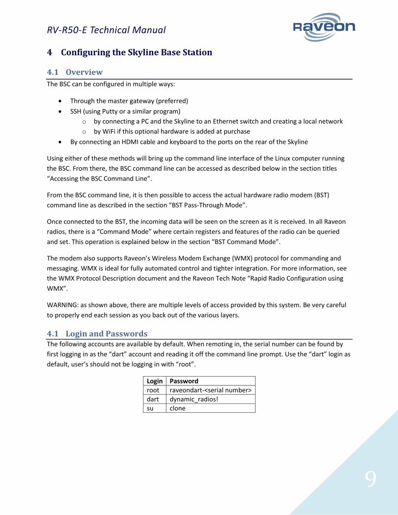
4.1 Login and Passwords The following accounts are available by default. When remoting in, the serial number can be found by
first logging in as the “dart” account and reading it off the command line prompt. Use the “dart” login as
default, user’s should not be logging in with “root”.
Login Password
root raveondart-<serial number>
dart dynamic_radios!
su clone
RV-R50-E Technical Manual
10
4.2 Accessing the BSC Command Line
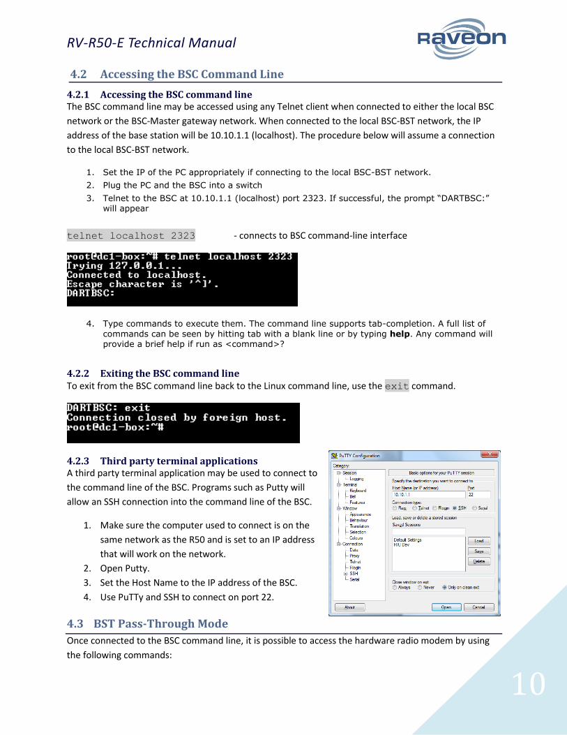
4.2.1 Accessing the BSC command line The BSC command line may be accessed using any Telnet client when connected to either the local BSC
network or the BSC-Master gateway network. When connected to the local BSC-BST network, the IP
address of the base station will be 10.10.1.1 (localhost). The procedure below will assume a connection
to the local BSC-BST network.
1. Set the IP of the PC appropriately if connecting to the local BSC-BST network.
2. Plug the PC and the BSC into a switch
3. Telnet to the BSC at 10.10.1.1 (localhost) port 2323. If successful, the prompt “DARTBSC:” will appear
telnet localhost 2323 - connects to BSC command-line interface
4. Type commands to execute them. The command line supports tab-completion. A full list of
commands can be seen by hitting tab with a blank line or by typing help. Any command will provide a brief help if run as <command>?
4.2.2 Exiting the BSC command line To exit from the BSC command line back to the Linux command line, use the exit command.
4.2.3 Third party terminal applications A third party terminal application may be used to connect to
the command line of the BSC. Programs such as Putty will
allow an SSH connection into the command line of the BSC.
1. Make sure the computer used to connect is on the
same network as the R50 and is set to an IP address
that will work on the network.
2. Open Putty.
3. Set the Host Name to the IP address of the BSC.
4. Use PuTTy and SSH to connect on port 22.
4.3 BST Pass-Through Mode
Once connected to the BSC command line, it is possible to access the hardware radio modem by using
the following commands:
RV-R50-E Technical Manual
11
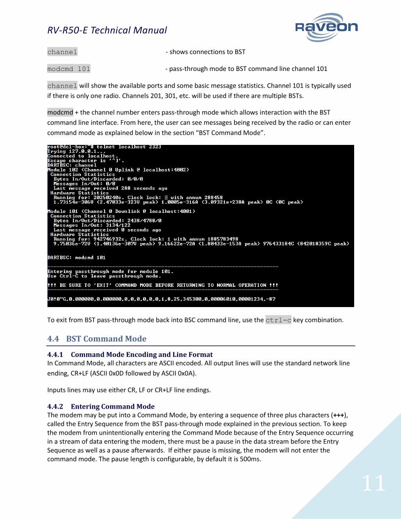
channel - shows connections to BST
modcmd 101 - pass-through mode to BST command line channel 101
channel will show the available ports and some basic message statistics. Channel 101 is typically used
if there is only one radio. Channels 201, 301, etc. will be used if there are multiple BSTs.
modcmd + the channel number enters pass-through mode which allows interaction with the BST
command line interface. From here, the user can see messages being received by the radio or can enter
command mode as explained below in the section “BST Command Mode”.
To exit from BST pass-through mode back into BSC command line, use the ctrl-c key combination.
4.4 BST Command Mode
4.4.1 Command Mode Encoding and Line Format In Command Mode, all characters are ASCII encoded. All output lines will use the standard network line
ending, CR+LF (ASCII 0x0D followed by ASCII 0x0A).
Inputs lines may use either CR, LF or CR+LF line endings.
4.4.2 Entering Command Mode The modem may be put into a Command Mode, by entering a sequence of three plus characters (+++), called the Entry Sequence from the BST pass-through mode explained in the previous section. To keep the modem from unintentionally entering the Command Mode because of the Entry Sequence occurring in a stream of data entering the modem, there must be a pause in the data stream before the Entry Sequence as well as a pause afterwards. If either pause is missing, the modem will not enter the command mode. The pause length is configurable, by default it is 500ms.
RV-R50-E Technical Manual
12
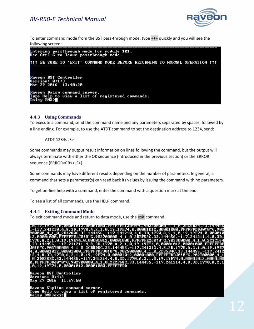
To enter command mode from the BST pass-through mode, type +++ quickly and you will see the following screen:
4.4.3 Using Commands To execute a command, send the command name and any parameters separated by spaces, followed by
a line ending. For example, to use the ATDT command to set the destination address to 1234, send:
ATDT 1234<LF>
Some commands may output result information on lines following the command, but the output will
always terminate with either the OK sequence (introduced in the previous section) or the ERROR
sequence (ERROR<CR><LF>).
Some commands may have different results depending on the number of parameters. In general, a
command that sets a parameter(s) can read back its values by issuing the command with no parameters.
To get on-line help with a command, enter the command with a question mark at the end.
To see a list of all commands, use the HELP command.
4.4.4 Exiting Command Mode To exit command mode and return to data mode, use the exit command.
RV-R50-E Technical Manual
13
Make sure to exit command mode before returning to BST pass-through mode, otherwise the radio
will not pass the required data through the system until command mode times out.
Alternatively, command mode will timeout after a configurable amount of time, by default 60 seconds.
4.5 BMX Commands
Use BMX commands when talking to the Base Station Controller (BSC) through the command line. See
Raveon’s BMX protocol document for a full list of commands.
4.6 Transceiver Command-Line Commands
Most of the operation with regards to the built-in transceiver are automatic within the system.
However, if the user wishes to access the Base Station Transceiver (BST) command line, as explained
above, it is possible to access various commands/settings pertaining to the transceiver. Please see “RV-
R50_Skyline_Programming_Manual” for a full list of commands.
5 Operational Modes and Parameters
5.1 Modes
5.1.1 LoRaLite In LoRaLite mode, the R50 will operate in a proprietary, decentralized, 1-3 channel frequency-agile
manner. This unique feature allows networks of R50 and M50 (Daisy) radios to operate with no central
network controller and no requirement that all radios are in range of each other. This enables the
reliability of multiple channels in the ISM band while allowing free-form network architectures as
required.
In LoRaLite mode, a number of configuration options are selectable:
1. Channel frequencies
2. Channel bandwidth
3. Channel data rate
To configure any individual channel, issue ATHP <channel>, where <channel> ranges from 1-3 to select
the channel. ATH will list the configuration of all channels. Once a channel to configure is selected, the
commands below will modify the parameters of the channel.
FCC regulations require that the R50/M50 not allow certain modes of operation. If the radio is placed in
a non-compliant configuration, this will be indicated upon entering Command Mode or when issuing the
SHOW command. The SHOW or ATH commands will detail what action was taken to correct the non-
compliant configuration.
5.1.2 Dart Dart is Raveon’s custom protocol meant for highly reliable, secure private networks. See the Dart
Protocol Specification for more details regarding this mode.
RV-R50-E Technical Manual
14
5.1.3 LoRaWAN LoRaWAN is a wide area network standard designed by the LoRa Aliiance. The aim of LoRaWAN is to
create a worldwide network standard which any LoRa-enabled devices can communicate. The R50 is
fully compliant with the LoRaWAN Specification 1.0.1 classes A, B and C. This means that the R50 can be
used with existing LoRaWAN compliant hardware and can be substituted or replaced by any LoRaWAN
compliant (specification 1.0.1) base station.
5.1.3.1 Class A
LoRaWAN class A is meant for battery-powered wireless devices and is the lowest power mode of
LoRaWAN. In this class, end nodes transmit at random intervals, on random channels and at various
BAUD rates to reduce the number of collisions. This random nature results in an even distribution of
bandwidth usage across the band. Each end node chooses a random transmit interval and then listens at
2 highly accurate receive times which are based off the end of the transmit packet. Typically, this
interval is 1 second. i.e. one end node finished transmission and opens up a receive slot exactly 1 second
later. If this radio does not receive a packet in this first reception window, it then opens a receive
window exactly 1 second later.
5.1.3.2 Class B
LoRaWAN class B is meant for beacon receive window management. This means that the base station
sends out a beacon to sync all of the wireless devices to listen at the same time for a reception. If an end
node has data to transmit, it completes the transmission at a random interval after the end of this
reception.
5.1.3.3 Class C
In LoRaWAN class C operation, each wireless device is constantly receiving. This mode provides more
flexibility with base station transmissions as it can receive at any time; there is no special window which
the base station has to transmit in.
5.2 Channel Frequency Plan
For the ISM band in North America, channel center frequency may be set between 902.5 - 927.8MHz for
125kHz channels and between 902.7 - 927.5MHz for 500kHz channels. Note also that a frequency
separation of 600kHz is enforced for 500kHz channels and 200kHz for 125kHz channels.
5.2.1 LoRaLite LoRaLite uses a 3-channel hopping plan incorporating 2 125kHz channels and 1 500kHz channel. The
specific channels can be set to any frequencies in the “LoRaLite Channel Plan” document but all radios in
the network must share the same frequencies. To keep it easy, the LoRaLite channels can be set with a
single command (A-Z) which will automatically load the 3 frequencies for that group.
To completely disable a channel, set ATFX 0. Note that disabling a channel will cause non-compliant
configurations if 125kHz channels are in use. All three channels must be enabled if 125kHz channels are
in use, and exactly two channels must be 125kHz.
RV-R50-E Technical Manual
15
5.2.2 LoRaLite Star LoRa Lite Star is a protocol designed to work in a star network topology with many Daisy radios
communicating with a central base station.
The uplink randomly transmits on 9 channels which matches the first bank of the LoRaWAN frequencies,
that is 8 125kHz channels from 902.3MHz-903.7MHz and 1 500kHz channel at 903MHz. The downlink
uses a single 500kHz channel set at 923.3MHz. Other banks can be used as well.
The radios operate similar to a LoRaWAN class C radio, i.e. they transmit when they have data to send
and otherwise are always receiving.
Spread Factor is configurable.
5.2.3 LoRaWAN
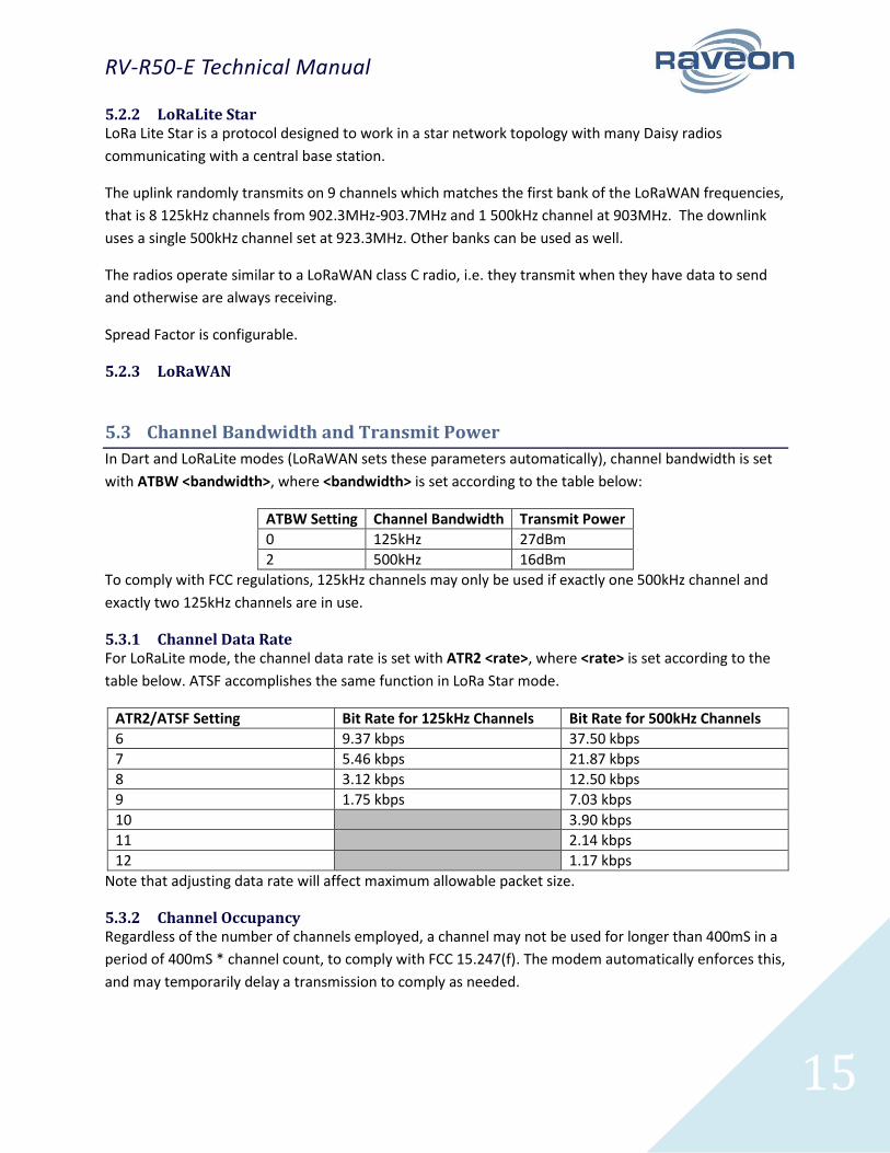
5.3 Channel Bandwidth and Transmit Power
In Dart and LoRaLite modes (LoRaWAN sets these parameters automatically), channel bandwidth is set
with ATBW <bandwidth>, where <bandwidth> is set according to the table below:
ATBW Setting Channel Bandwidth Transmit Power
0 125kHz 27dBm
2 500kHz 16dBm
To comply with FCC regulations, 125kHz channels may only be used if exactly one 500kHz channel and
exactly two 125kHz channels are in use.
5.3.1 Channel Data Rate For LoRaLite mode, the channel data rate is set with ATR2 <rate>, where <rate> is set according to the
table below. ATSF accomplishes the same function in LoRa Star mode.
ATR2/ATSF Setting Bit Rate for 125kHz Channels Bit Rate for 500kHz Channels
6 9.37 kbps 37.50 kbps
7 5.46 kbps 21.87 kbps
8 3.12 kbps 12.50 kbps
9 1.75 kbps 7.03 kbps
10 3.90 kbps
11 2.14 kbps
12 1.17 kbps
Note that adjusting data rate will affect maximum allowable packet size.
5.3.2 Channel Occupancy Regardless of the number of channels employed, a channel may not be used for longer than 400mS in a
period of 400mS * channel count, to comply with FCC 15.247(f). The modem automatically enforces this,
and may temporarily delay a transmission to comply as needed.

RV-R50-E Technical Manual
16
5.4 Device Addressing
5.4.1 ID Addressing Basics ID addressing is used to differentiate one modem from another. Each must have a unique number
programmed into them, so that when a position report is received, the modem that sent the message
can be identified. This is called the MYID of the unit that sent the message.
Each modem has a MYID programmed into it, and is represented as a 4 digit hexadecimal number.
Addresses between 0001-FFFF are valid. The Unit Address is programmed with the MYID xxxx
command, and the ID of the destination modem it sends its messages to (the Destination Address) is
configured with the ATDT xxxx command.
The factory default MYID in all modems is 1234, and 1234 is also the default for the Destination ID also.
The default Address Mask is F000, which means the modem will receive a transmission from any other
modem as long as the first digit of the destination address matches, in this case, is a 1.
Make sure you set the MYID of each modem in your system to a different number.
For example, to set the ID of your modem to 17, enter:
MYID 17 <enter>
To set your modem to send its position and status data to modem number 1, enter:
ATDT 1 <enter>
To set your address mask to receive all messages from units with IDs 1-999, and exclude 1000-9999,
enter
ATMK F000 <enter>
6 Data Handling
6.1 Data Transmission
To transmit data, use the proper BMX command (See Raveon’s BMX protocol document for a full list of
commands and syntax). When a full packet of data has been collected into the internal buffer of the
modem; there is a pause in the data per ATR3; or the maximum packet size is reached, the modem will
automatically key its transmitter, and send the data over the air.
6.2 Data Reception
When the modem receives data over the air, it checks it for errors, and if it is error-free, it will be
received by the R50. There are a few ways to access this incoming data as described below.
RV-R50-E Technical Manual
17
6.2.1 Master Gateway The ideal method to capture the data from an R50 Base Station is by means of the Master Gateway. The
Master Gateway can be configured to route incoming messages various output streams as needed.
6.2.2 BST Pass-Through mode To view the raw data being received, enter BST pass-through mode as described above. This will allow
access to the BST incoming messages which can be viewed and copied elsewhere.
7 Configuration
7.1 Network Configuration
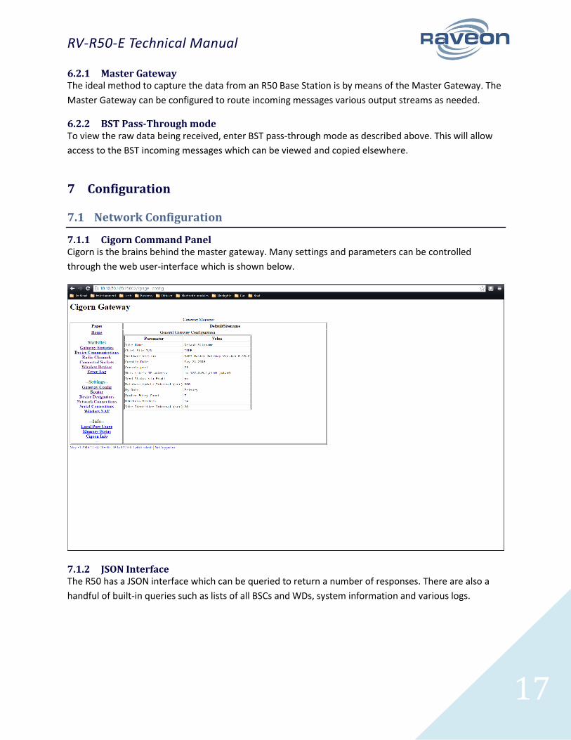
7.1.1 Cigorn Command Panel Cigorn is the brains behind the master gateway. Many settings and parameters can be controlled
through the web user-interface which is shown below.
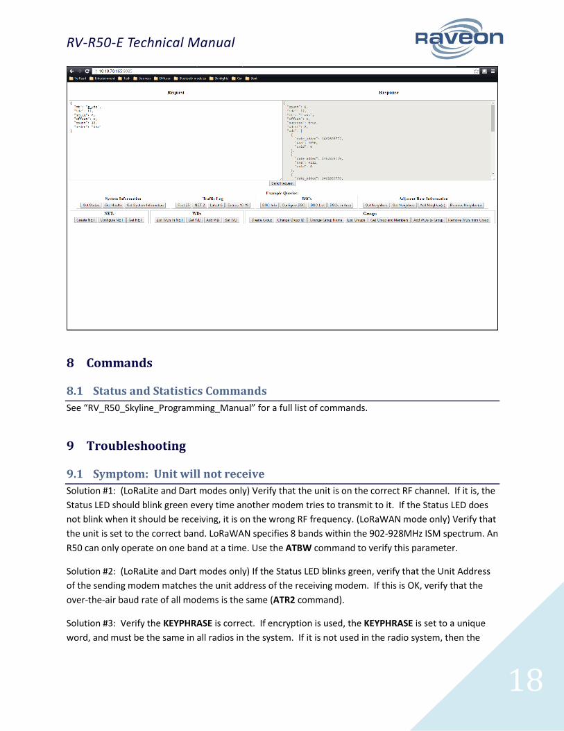
7.1.2 JSON Interface The R50 has a JSON interface which can be queried to return a number of responses. There are also a
handful of built-in queries such as lists of all BSCs and WDs, system information and various logs.
RV-R50-E Technical Manual
18
8 Commands
8.1 Status and Statistics Commands
See “RV_R50_Skyline_Programming_Manual” for a full list of commands.
9 Troubleshooting
9.1 Symptom: Unit will not receive
Solution #1: (LoRaLite and Dart modes only) Verify that the unit is on the correct RF channel. If it is, the
Status LED should blink green every time another modem tries to transmit to it. If the Status LED does
not blink when it should be receiving, it is on the wrong RF frequency. (LoRaWAN mode only) Verify that
the unit is set to the correct band. LoRaWAN specifies 8 bands within the 902-928MHz ISM spectrum. An
R50 can only operate on one band at a time. Use the ATBW command to verify this parameter.
Solution #2: (LoRaLite and Dart modes only) If the Status LED blinks green, verify that the Unit Address
of the sending modem matches the unit address of the receiving modem. If this is OK, verify that the
over-the-air baud rate of all modems is the same (ATR2 command).
Solution #3: Verify the KEYPHRASE is correct. If encryption is used, the KEYPHRASE is set to a unique
word, and must be the same in all radios in the system. If it is not used in the radio system, then the

RV-R50-E Technical Manual
19
KEYPHRASE in all units must be disabled or left at the factory default. To disable encryption, use the
KEYPHRASE 0 command. The factory default KEYPHRASE is RAVEON, in all capital letters.
9.2 Symptom: Receive light blinks, but no data is received
9.3 Symptom: Long delay before transmitting
Solution #1: Verify that serial port timeout is OK. The ATR3 command sets the number of milliseconds
that the modem will look for in the serial input data stream. If a pause greater than this value happens,
the modem will transmit. If the ATG0 parameter is set very large, say 2000, this means 2 seconds, and
the modem may simply be waiting a long time. Typical settings for this parameter are 20 (20mS).
10 Mechanical
10.1 Dimensions
10.2 Mounting

RV-R50-E Technical Manual
20
11 NOTICE
There are no user-serviceable points inside this transceiver. All service work must be referred to your
Authorized Service Center or Raveon Technologies Service Department.
11.1 Safety Training information
Always use this radio with the antenna supplied with it. This radio is restricted to occupational use.
Work related operations are permitted only when the radio operator has the knowledge to control the
exposure conditions of its passengers and bystanders by maintaining the minimum separation distance.
Failure to observe these restrictions may result in exceeding the FCC RF exposure limits.
12 FCC Compliance Information
This device complies with part 15 of the FCC Rules. Operation is subject to the following two conditions:
(1) This device may not cause harmful interference, and (2) this device must accept any interference
received, including interference that may cause undesired operation.
Changes or modifications not expressly approved by the party responsible for compliance could void the
user’s authority to operate the equipment.
NOTE: The manufacturer is not responsible for any radio or TV interference caused by unauthorized
modifications to this equipment. Such modifications could void the user’s authority to operate the
equipment.
The Federal Communications Commission (FCC), with its action in ET Docket 93-62, has adopted a safety
standard for human exposure to Radio Frequency (RF) electromagnetic energy emitted by FCC-certified
equipment. This product meets the uncontrolled environmental limits as stated in OET-65C (01-01)
when operated in accordance with the operation guidelines described in this manual. Proper operation
of this radio device according to the instructions in this publication will result in user exposure
substantially below the FCC recommended limits.
This equipment generates, uses, and radiates radio frequency energy, and if not installed and used in
accordance with the instructions, may cause harmful interference. However, there is no guarantee that
interference will not occur. If this equipment does cause interference to radio or television reception,
which can be determined by turning the equipment off and on, the user is encouraged to correct the
interference by one of the following measures:
• Reorient or relocate the receiving antenna.
• Increase separation between the equipment and receiver.
• Connect the equipment to an outlet on a circuit different from which the receiver is connected.
• Consult the dealer or an experienced radio/TV technician.
RV-R50-E Technical Manual
21
13 Warranty
Limited One Year Warranty
If within one year from date of purchase, this product fails due to a defect in material or workmanship, Raveon
Technologies, Incorporated will repair or replace it, at Raveon’s sole discretion. This warranty is extended to the
original consumer purchaser only and is not transferable.
This warranty does not apply to: (a) product damage caused by accident, dropping or abuse in handling, acts of
God or any negligent use; (b) units which have been subject to unauthorized repair, opened, taken apart or
otherwise modified; (c) units not used in accordance with instructions; (d) damages exceeding the cost of the
product; (e) batteries; (f) the finish on any portion of the product, such as surface and/or weathering, as this is
considered normal wear and tear; (g) transit damage, initial installation costs, removal costs, or reinstallation
costs; (h) damage due to lighting, floods, fire, or earthquakes, (i) connectors, (j) antennas, or (k) belt clips.
RAVEON TECHNOLOGIES INCORPORATED WILL NOT BE LIABLE FOR INCIDENTAL OR CONSEQUENTIAL DAMAGES.
SOME STATES DO NOT ALLOW THE EXCLUSION OR LIMITATION OF INCIDENTAL OR CONSEQUENTIAL DAMAGES, SO
THE ABOVE LIMITATION OR EXCLUSION MAY NOT APPLY TO YOU. THIS WARRANTY IS IN LIEU OF ALL OTHER
EXPRESS OR IMPLIED WARRANTIES. ALL IMPLIED WARRANTIES, INCLUDING THE WARRANTY OF MERCHANTABILITY
AND THE WARRANTY OF FITNESS FOR A PARTICULAR PURPOSE, ARE HEREBY MODIFIED TO EXIST ONLY AS
CONTAINED IN THIS
LIMITED WARRANTY, AND SHALL BE OF THE SAME DURATION AS THE WARRANTY PERIOD STATED ABOVE. SOME
STATES DO NOT ALLOW LIMITATIONS ON THE DURATION OF AN IMPLIED WARRANTY, SO THE ABOVE LIMITATION
MAY NOT APPLY TO YOU.
This warranty gives you specific legal rights and you may also have other rights which vary from state to state.
Warranty service is available by mailing postage prepaid to:
Raveon Technologies Corporation
2320 Cousteau Court
Vista, CA 92081
To obtain warranty service, include a copy of the original sales receipt or invoice showing the date, location, and
price of purchase. Include a written description of the problem with the product, a phone number and name of
person who may be contacted regarding the problem, and the address to where the product should be returned.
Products repaired under warranty will typically have their program memories erased and reset to factory default
settings.