Embed Size (px)
Citation preview

FBP FieldBusPlug
1SAJ 929 499 R0001 F
© ABB STOTZ-KONTAKT GmbH
03/2010
www.abb.de/stotz-kontakt
UTF21-FBP DTM V2.0.3
Technical Manual
V6
USB to FBP
UTF21-FBP

- 2 -UTF21-FBP and DTM for UTF21-FBP
UTF21-FBP
and Device Type Manager (DTM) for UTF21-FBP
Technical Manual
FieldBusPlug / Issue: 03.2010
V 6
Terminology
Term/Acronym Description
Device Type Manager (DTM) Software component (device driver) for confi guring, diagnosing, forcing, displaying the measured variables, etc. of a fi eld device. It is familiar with the way the device works and supplies device specifi c documentation.
Frame Application (FA) Frame application (run time environment) in accordance with the FDT specifi cation for operating DTMs
Field Device Tool (FDT) The FDT concept describes the interface between a frame application and the device-specifi c software (DTM = Device Type Manager) of the device manufacturer. It enables devices produced by different manufacturers and different fi eldbuses to be integrated in a single system. Currently supporting fi eldbus protocols for PROFIBUS and HART.
Please note the following
Target group
This description is intended for the use of trained specialists in electrical installation and control and automation engineering, who are familiar with the applicable national standards.
Safety requirements
The responsible staff must ensure that the application or use of the products described satisfy all the requirements for safety, including all the relevant laws, regulations, guidelines and standards.
Using this Handbook
Symbols: This technical document contains sentinels to point the reader to important information, potential risks and precaution information. The following symbols are used:
Sign to indicate a potential dangerous situation that can cause damage of the PDP22 or connected devices or the environment.
Sign to indicate important information and conditions.
Sign that indicates a potential dangerous situation that can cause human injuries.

- 3 - UTF21-FBP and DTM for UTF21-FBP
UTF21-FBP
and Device Type Manager (DTM) for UTF21-FBP
Technical Manual
FieldBusPlug / Issue: 03.2010
V 6
Content
1 Introduction ..........................................................................................................................................4
2 UTF21-FBP Description .......................................................................................................................5
3 Installing the UTF21-FBP Hardware Driver ..........................................................................................6
4 UTF21-FBP for FBP Device Confi guration ...........................................................................................7
5 Using UTF21-FBP with AC500 CPU as programming cable .............................................................11
6 Frequently asked Questions ...............................................................................................................18
7 Technical Data ....................................................................................................................................19

- 4 -UTF21-FBP and DTM for UTF21-FBP
UTF21-FBP
and Device Type Manager (DTM) for UTF21-FBP
Technical Manual
FieldBusPlug / Issue: 03.2010
V 6
1 Introduction
This document describes the UTF21-FBP FieldBus Plug. It can be used
as communication adapter for FBP devices to do device parameterization and confi guration using the device specifi c Device Type Managers (DTM) as available for e.g. the UMC22
to offer a 3rd serial interface for the AC500 that can be used as serial programming interface.
Organization of this manual
This manual is split as follows:
Description of the UTF21
Installation guide of the low-level Windows driver
Short tutorial on how to use the UTF21-FBP for UMC and other FBP device confi guration
Description on how to use the UTF21-FBP together with AC500
FAQ
Technical Data
For users interested in FBP device confi guraiton via DTM the section "UTF21-FBP for FBP Device Confi guration" is most relevant
For AC500 users the sections "Installing the UTF21-FBP Hardware" and "UTF21 for AC500" are most relevant
The UTF21-FBP communication DTM is on the PBDTM CD 1SAJ924012R0003 or later.
•
•
•
•
•
•
•
•

- 5 - UTF21-FBP and DTM for UTF21-FBP
UTF21-FBP
and Device Type Manager (DTM) for UTF21-FBP
Technical Manual
FieldBusPlug / Issue: 03.2010
V 6
2 UTF21-FBP Description
The UTF21-FBP consist of the following parts:
1 communication adapter to connect a PC via USB to FBP or AC500
1 USB extension cable
1 CD with the Windows device driver
2.1 Hardware
The UTF21-FBP is a communication adapter that allows to connect FBP devices to a PC or Laptop. One side of the UTF21-FBP can be plugged into the USB (Universal Serial Bus) interface of a PC. The other side can be connected to the neutral interface (M12 connector) of a FieldbusPlug device or the AC500.
The fi gure below shows the UTF21-FBP. Three LEDs show the status of the device. The power LED is always on and indicates that the 24 V are available. The RXD (Receive) and TXD (Transmit) LEDs indicate traffi c in the corresponding direction.
2.2 CD Content
The UTF21 installation CD contains the directory
Hardware Driver: This directory contains the low level hardware driver.
1SAJ 929 499 R0001 F
© ABB STOTZ-KONTAKT GmbH
03/2010
www.abb.de/stotz-kontakt
UTF21-FBP DTM V2.0.3
•
•
•
•

- 6 -UTF21-FBP and DTM for UTF21-FBP
UTF21-FBP
and Device Type Manager (DTM) for UTF21-FBP
Technical Manual
FieldBusPlug / Issue: 03.2010
V 6
3 Installing the UTF21-FBP Hardware Driver
Before plug in the UTF21-FBP into the USB port of your PC or Laptop ensure that the device driver is installed. Else a wrong device driver might get installed (depending on your Windows settings).
Insert the CD in the CD drive and open the index.html fi le if it is not automatically opened (autostart). Select either the right or left ok button depending on your UTF21-FBP use case. Now install the Windows device driver. The setup usually does not require any user interaction.
Plug in the UTF21-FBP device into a USB port. Please use a USB port that can drive the maximum current allowed in the USB spec (500 mA). This is typically a USB port directly on your Laptop or PC but not the ones often provided in keyboards etc.
After a short while an information should be shown that the new hardware is installed and ready for use. Please navigate to the Windows control panel, open the system properties dialog and select the device manager (workfl ow for Windows XP). The menu order and names might be different for other Windows versions. The UTF21-FBP is represented as USB Serial Port. In the example shown below it is COM4.
If a port greater than COM5 was used from the operating system please open the USB Serial port device and change the port number (port settings -> advanced) to a lower number. The port number is needed later on in the UTF21 DTM and the AC500 Control Builder..
Now the Windows device driver for the UTF21-FBP is installed and ready for use.
1.
2.
3.
4.

- 7 - UTF21-FBP and DTM for UTF21-FBP
UTF21-FBP
and Device Type Manager (DTM) for UTF21-FBP
Technical Manual
FieldBusPlug / Issue: 03.2010
V 6
4 UTF21-FBP for FBP Device Confi guration
4.1 Introduction
The UTF21-FBP communication adapter together with the UTF21 DTM can be used to confi gure a single FBP device such as the UMC22-FBP using its device specifi c DTM. The UTF21 DTM is a gateway DTM conforming to FDT 1.2. It supports the following DTM functions:
About: Display of general information, directly related to the DTM software.
Confi guration: Offl ine change of parameters during the planning phase.
It is assumed that the reader is familiar with the principles of the FDT/DTM concept. Therefore only UTF21-FBP specifi cs are described here. Good introduction material about the FDT/DTM technology is available on the FDT Group's website: http://www.fdt-jig.org
The frame application used in this document for the screenshots is the fdtContainer from the M&M company.
The next two fi gures show the hardware and software setup with the UMC22-FBP as an example for a FieldbusPlug device.
UMC22-FBP
PWRRXDTXD
USB M12
Installed Software:• FDT/DTM Frame Application• UMC22 Device DTM• UTF21 Communication DTM• Low level Serial Driver
UTF21-FBP USB �� FBP Interface
The UMC22-FBP is connected via UTF21-FBP with a laptop. On the laptop the UTF21 DTM and the PBDTM are installed together with a FDT/DTM frame application. With this setup single UMCs or other FBP devices providing a DTM can be confi gured.
•
•

- 8 -UTF21-FBP and DTM for UTF21-FBP
UTF21-FBP
and Device Type Manager (DTM) for UTF21-FBP
Technical Manual
FieldBusPlug / Issue: 03.2010
V 6
Device with FBPInterface
(e.g. UMC22)
UTF21-FBP
Serial InterfaceDriver
UTF21-FBPCOM DTM
Device specificDTM
WindowsLow level hardwaredriver as installed insection 1 (e.g. COM4)
Frame Application(e.g. dtmContainer)where the DTMs arerunning inside.
Device specific DTM(e.g. PBDTM) with a graphicaluser interface for deviceparameterization and onlinemonitoring
Software
Hardware
Communication DTMthat provide parameterread/write servicesto device DTMs
This fi gure presents the different hardware and software components and their communication relations. Simply spoken the FDT/DTM concept defi nes that each hardware component is represented with a 'device driver' (DTM). This is indicated with the same dashed line style for the corresponding hardware and software components.

- 9 - UTF21-FBP and DTM for UTF21-FBP
UTF21-FBP
and Device Type Manager (DTM) for UTF21-FBP
Technical Manual
FieldBusPlug / Issue: 03.2010
V 6
4.2 First Steps
This section gives a quick-start on how to confi gure a device (UMC22) using the UTF21-FBP. It is assumed that the reader is familiar with the principles of FDT/DTM. Therefore only UTF21-FBP specifi cs are described here.
Updating the DTM Catalog
Most FDT/DTM frame applications require an update of the DTM catalog before newly installed DTMs are visible. The concrete steps depend on the used frame application. The following fi gure shows the Device Catalogue window of the fdtContainer Frame Application after updating the catalog. Beside other installed DTMs the ABB UTF21-FBP DTM appears in the list of installed DTMs.
.
Confi guring the UTF21-FBP DTM
Insert the UTF21-FBP DTM into the network tree. Then right click on the UTF21-FBP icon and select Additional Functions -> Confi guration. A dialog opens where the baud rate and the port can be confi gured. Select the right communication port (see section Installing the Hardware Device Driver). Presently only 9600 Bauds can be used as communication speed. Therefore this value must not be changed.
The fi gure below shows the UTF21-FBP confi guration dialog.
- 10 -UTF21-FBP and DTM for UTF21-FBP
UTF21-FBP
and Device Type Manager (DTM) for UTF21-FBP
Technical Manual
FieldBusPlug / Issue: 03.2010
V 6
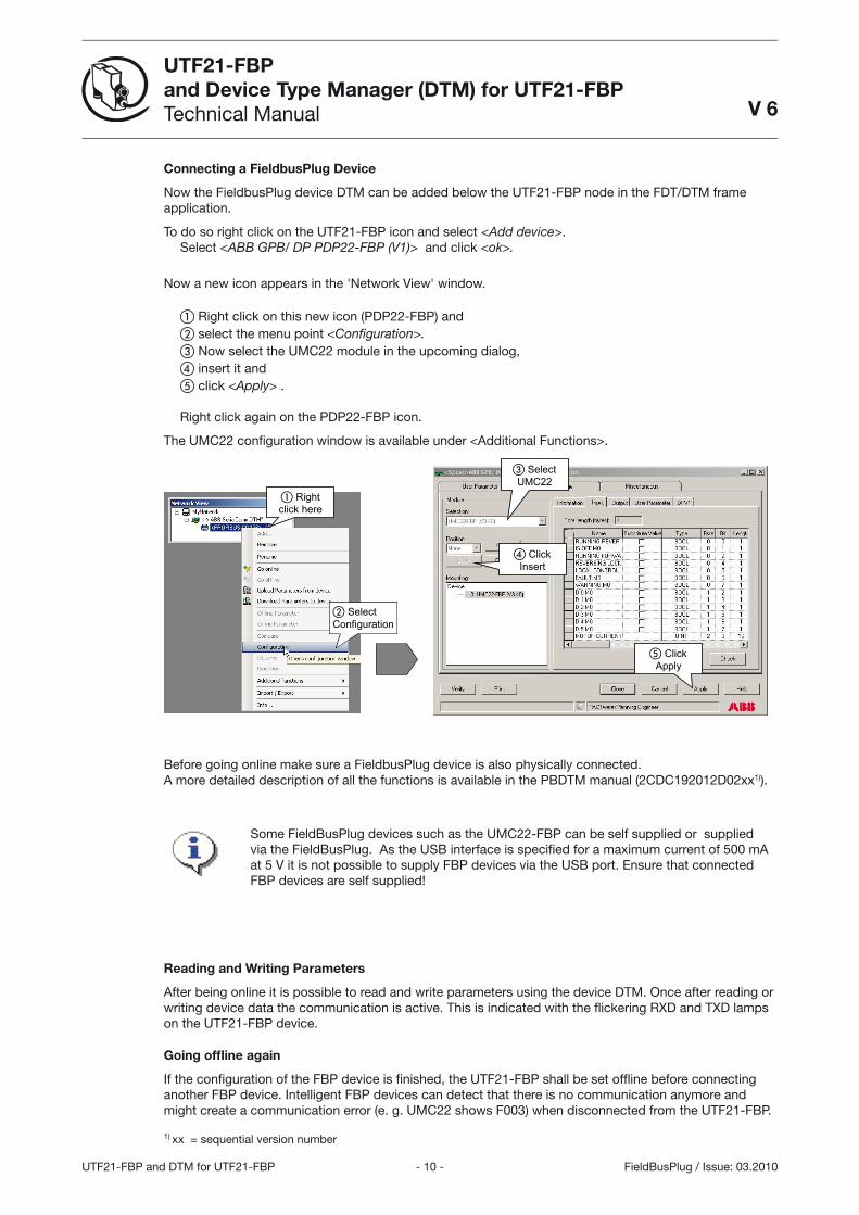
Connecting a FieldbusPlug Device
Now the FieldbusPlug device DTM can be added below the UTF21-FBP node in the FDT/DTM frame application.
To do so right click on the UTF21-FBP icon and select <Add device>. Select <ABB GPB/ DP PDP22-FBP (V1)> and click <ok>.
Now a new icon appears in the 'Network View' window.
� Right click on this new icon (PDP22-FBP) and� select the menu point <Confi guration>. � Now select the UMC22 module in the upcoming dialog, � insert it and� click <Apply> .
Right click again on the PDP22-FBP icon.
The UMC22 confi guration window is available under <Additional Functions>.
Rightclick here
SelectConfiguration
SelectUMC22
ClickInsert
ClickApply
Before going online make sure a FieldbusPlug device is also physically connected. A more detailed description of all the functions is available in the PBDTM manual (2CDC192012D02xx1)).
Some FieldBusPlug devices such as the UMC22-FBP can be self supplied or supplied via the FieldBusPlug. As the USB interface is specifi ed for a maximum current of 500 mA at 5 V it is not possible to supply FBP devices via the USB port. Ensure that connected FBP devices are self supplied!
Reading and Writing Parameters
After being online it is possible to read and write parameters using the device DTM. Once after reading or writing device data the communication is active. This is indicated with the fl ickering RXD and TXD lamps on the UTF21-FBP device.
Going offl ine again
If the confi guration of the FBP device is fi nished, the UTF21-FBP shall be set offl ine before connecting another FBP device. Intelligent FBP devices can detect that there is no communication anymore and might create a communication error (e. g. UMC22 shows F003) when disconnected from the UTF21-FBP.
1) xx = sequential version number

- 11 - UTF21-FBP and DTM for UTF21-FBP
UTF21-FBP
and Device Type Manager (DTM) for UTF21-FBP
Technical Manual
FieldBusPlug / Issue: 03.2010
V 6
5 Using UTF21-FBP with AC500 CPU as programming cable
To be able to use the UTF21-FBP USB Adapter together with the AC500 CPUs, please respect the following procedure and advices.
Install the USB Driver, see previous chapter: “Installing the UTF21-FBP Hardware driver” of this manual
The FBP serial interface of a CPU is a specifi c serial interface which supports the FBP-neutral protocol. When a FBP has to be used onto an AC500 CPU, the FBP serial interface has to be confi gured to work with and is set to “FBP-Slave”.
When no FBP will be used, which is then our case, the serial interface has to be confi gured to “FBP-None” and then the FBP serial interface is no more assigned to the FBP protocol.
If the CPU is confi gured as FBP slave, you have to modify this setting. Two possibilities are given:
Put the CPU in “Mode 01” (no project load at power start) see further at the end of the document
Or by using an other serial interface (COM1 or COM2) to access the CPU with the PS501 Software modify the confi guration, see also further at the end of the docuement
Do not plug the UTF21-FBP adapter to the USB interface before performing the following steps.
Check that the confi guration of the FBP-serial interface of the used AC500 CPU is set to “FBP-None”, otherwise it will not work.
Before inserting the UTF21-FBP adapter into an USB interface, you should check and if necessary close an already opened 3S Gateway.
In the Windows Start line, click on the 3S Gateway symbol with the right mouse button and select <Exit>.
The Gateway is closed.
1.

- 12 -UTF21-FBP and DTM for UTF21-FBP
UTF21-FBP
and Device Type Manager (DTM) for UTF21-FBP
Technical Manual
FieldBusPlug / Issue: 03.2010
V 6
Insert the UTF21-FBP adapter to a non used FBP interface. A window appears to indicate that a new Hardware has been detected and Windows is searching for the driver. You could have to wait a while but normally no actions are requested from the user.
A COM-port of the PC has to be determined for the UTF21-FBP adapter. With the left mouse button, click on <Start> from the Windows bar, and go to
� Settings � Control Panel � Hardware � Device Manager
2.
3.
�
� �
�
�

- 13 - UTF21-FBP and DTM for UTF21-FBP
UTF21-FBP
and Device Type Manager (DTM) for UTF21-FBP
Technical Manual
FieldBusPlug / Issue: 03.2010
V 6
Then by clicking with the right mouse button on
� USB Serial port and � Properties
the automatically confi gured COM port can be change if not OK.
�
�
In the following example, the UTF21-FBP adapter will use the COM4.

- 14 -UTF21-FBP and DTM for UTF21-FBP
UTF21-FBP
and Device Type Manager (DTM) for UTF21-FBP
Technical Manual
FieldBusPlug / Issue: 03.2010
V 6
The CoDeSys Gateway channel should also be confi gured. Then start CoDeSys (PS501) and open an AC500 Project (could be an already saved or a new one).
Go to the menu <Online>, choose <Communication parameters>… and click onto the selection
A new window is open and the Gateway can be confi gured. Choose <New> and type for example into the Name: USB-FBP_AC_4, and select the driver <Serial (RS232)> into the list. Then press OK.
A new Gateway is created and you have to confi gure the communication parameters:
4.
- 15 - UTF21-FBP and DTM for UTF21-FBP
UTF21-FBP
and Device Type Manager (DTM) for UTF21-FBP
Technical Manual
FieldBusPlug / Issue: 03.2010
V 6
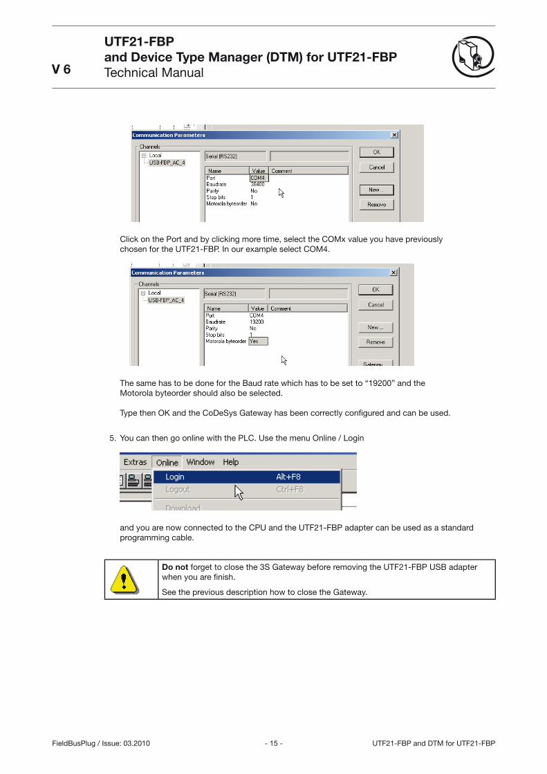
Click on the Port and by clicking more time, select the COMx value you have previously chosen for the UTF21-FBP. In our example select COM4.
The same has to be done for the Baud rate which has to be set to “19200” and the Motorola byteorder should also be selected.
Type then OK and the CoDeSys Gateway has been correctly confi gured and can be used.
You can then go online with the PLC. Use the menu Online / Login
and you are now connected to the CPU and the UTF21-FBP adapter can be used as a standard programming cable.
Do not forget to close the 3S Gateway before removing the UTF21-FBP USB adapter when you are fi nish.
See the previous description how to close the Gateway.
5.

- 16 -UTF21-FBP and DTM for UTF21-FBP
UTF21-FBP
and Device Type Manager (DTM) for UTF21-FBP
Technical Manual
FieldBusPlug / Issue: 03.2010
V 6
5.1 Using UTF21-FBP with AC500 -
If the FBP Interface of the CPU is not confi gured to “FBP-None”, please fi nd under the procedure to access the CPU and if necessary to change the confi guration.
NOTE The default confi guration of the CPU when produced is always “FBP-None”
5.2 Setting the “Mode 01” of the CPU
The “Mode 01” of the CPU is activated by switching off the CPU, pressing the <RUN> button on the front of the CPU and remain it pressed while the power is going up and until the indication “MOD 01” appears on the CPU display. Then the CPU can be also accessed from the FBP interface.
5.3 Changing the FBP interface confi guration by using PS501 Control Builder
Start the PS501 Software and load the PLC application of your PLC. If it was the last opened it will be automatically loaded by the software.
Select the register “Resources” on the bottom left of the screen
then double-click on “PLC Confi guration”
A window appears with the AC500 CPU confi guration.
Click on the “+” near the AC500 to open the tree.
Click o the “+” of the Interfaces, the interfaces are then displayed:

- 17 - UTF21-FBP and DTM for UTF21-FBP
UTF21-FBP
and Device Type Manager (DTM) for UTF21-FBP
Technical Manual
FieldBusPlug / Issue: 03.2010
V 6
The FBP interface is set to “FBP-Slave” and has to be reset to “FBP-None”.
Click on the “FBP-Slave” indication with the right mouse button, a new window appears:
Go to “Replace element” and select “FBP-None”.
The project has to be reloaded into the CPU by using the menu “Online / Login”
The project has changed and will then be reloaded to the CPU.
The FBP Interface of the CPU is now good confi gured and the normal procedure can be followed to install and use the UTF21-FBP adapter.

- 18 -UTF21-FBP and DTM for UTF21-FBP
UTF21-FBP
and Device Type Manager (DTM) for UTF21-FBP
Technical Manual
FieldBusPlug / Issue: 03.2010
V 6
6 Frequently asked Questions
DTM Specifi c Questions:
Q: After going online there is no read / write button on the device DTM visible.
A: The device DTM window was already open before being online. Close the device DTM window and reopen it again. Then the read/write buttons are available.
Q: Reading or writing parameters ends up in a timeout.
A: There might be different issues that can cause this. But most probably the wrong communication port is used. Ensure that the UTF21-FBP uses the right port.
Q: Is it possible to connect more than one UTF21-FBP interface to a PC.
A: No, only one device can be connected to one PC
Q: How can commissioning of a whole line of FieldbusPlug devices work if only one device at a time can be confi gured?
A: If many FBP devices should be confi gured it might be more effi cient to use a PROFIBUS class II master interface instead of the UTF21-FBP interface. See the PBDTM documentation for further information. But it is also possible to confi gure multiple FBP devices using the UTF21-FBP. Just save the project under a different names (e.g Pump1, Pump2 ...). So the confi guration data for all confi gured devices can be kept for later reference. If the parameters of a specifi c device shall be changed later on the corresponding project can just be loaded.
General
Q: The power lamp of the UTF21-FBP is off
A: There are mainly two possible reasons: The device driver is not installed correctly and therefore the device is not active. Or the connected FieldbusPlug device is not self supplied and current consumption is too high so that the current limitation in the USB port or the UTF21-FBP was activated. Supply the connected device separately and wait a view minutes until the protection element cooled down.
- 19 - UTF21-FBP and DTM for UTF21-FBP
UTF21-FBP
and Device Type Manager (DTM) for UTF21-FBP
Technical Manual
FieldBusPlug / Issue: 03.2010
V 6
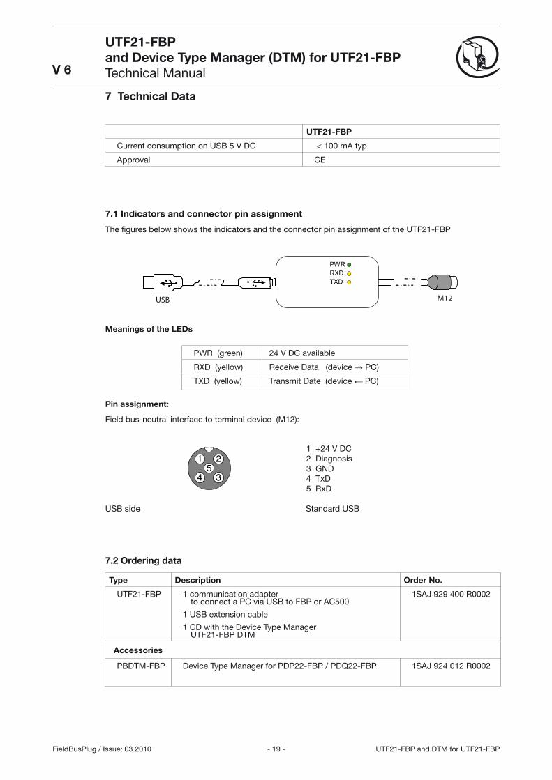
7 Technical Data
UTF21-FBP
Current consumption on USB 5 V DC < 100 mA typ.
Approval CE
7.1 Indicators and connector pin assignment
The fi gures below shows the indicators and the connector pin assignment of the UTF21-FBP
PWRRXDTXD
USB M12
Meanings of the LEDs
PWR (green) 24 V DC available
RXD (yellow) Receive Data (device � PC)
TXD (yellow) Transmit Date (device � PC)
Pin assignment:
Field bus-neutral interface to terminal device (M12):
1 +24 V DC2 Diagnosis3 GND4 TxD5 RxD
USB side Standard USB
7.2 Ordering data
Type Description Order No.
UTF21-FBP 1 communication adapter to connect a PC via USB to FBP or AC500
1 USB extension cable
1 CD with the Device Type ManagerUTF21-FBP DTM
1SAJ 929 400 R0002
Accessories
PBDTM-FBP Device Type Manager for PDP22-FBP / PDQ22-FBP 1SAJ 924 012 R0002

- 20 -UTF21-FBP and DTM for UTF21-FBP
UTF21-FBP
and Device Type Manager (DTM) for UTF21-FBP
Technical Manual
FieldBusPlug / Issue: 03.2010
V 6
7.3 Mechanical dimensions
252510
210
2
5151
ca. 1
540
ca. 1
540
PWR
RX
D
TXD
UTF21-FBP Mechanical dimensions All dimensions in mm.


Man
ual N
o.
ABB STOTZ-KONTAKT GmbH
Eppelheimer Straße 82 Postfach 10168069123 Heidelberg 69006 HeidelbergGermany Germany
Telephone +49 (0) 6221 701- 0 Telefax +49 (0) 6221 701- 240E-mail [email protected] http://www.abb.de/stotz-kontakt
2CD
C19
0 02
4 D
0204
03
.201
0