Embed Size (px)
Citation preview
TECHNICAL MANUAL
TRANSLATION OF THE ORIGINAL TECHNICAL MANUAL! EN
DIAPHRAGM PUMP 409.2...e / 410.2...e
INTRODUCTION
2 www.sera-web.com
NOTE
Record the exact type and serial number here ► can be read off the type plate on the pump.These data are important in the case of queries or for ordering spare and/or wear parts and must always be stated.
TYPE:
SERIAL NO:
NOTE
Keep the operating manual for future use!
ATTENTION
Subject to technical modifications!
Quality notes
The sera quality management and quality assurance system is certified in accordance with DIN EN ISO 9001:2015.The sera product complies with the applicable safety requirements and accident prevention regulations.
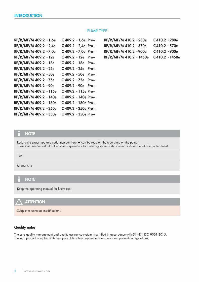
PUMP TYPE
RF/R/MF/M 409.2 - 1,6e C 409.2 - 1,6e Pro+ RF/R/MF/M 410.2 - 280e C 410.2 - 280eRF/R/MF/M 409.2 - 2,4e C 409.2 - 2,4e Pro+ RF/R/MF/M 410.2 - 570e C 410.2 - 570eRF/R/MF/M 409.2 - 7,0e C 409.2 - 7,0e Pro+ RF/R/MF/M 410.2 - 900e C 410.2 - 900eRF/R/MF/M 409.2 - 12e C 409.2 - 12e Pro+ RF/R/MF/M 410.2 - 1450e C 410.2 - 1450eRF/R/MF/M 409.2 - 18e C 409.2 - 18e Pro+RF/R/MF/M 409.2 - 25e C 409.2 - 25e Pro+RF/R/MF/M 409.2 - 50e C 409.2 - 50e Pro+RF/R/MF/M 409.2 - 75e C 409.2 - 75e Pro+RF/R/MF/M 409.2 - 90e C 409.2 - 90e Pro+RF/R/MF/M 409.2 - 115e C 409.2 - 115e Pro+RF/R/MF/M 409.2 - 140e C 409.2 - 140e Pro+RF/R/MF/M 409.2 - 180e C 409.2 - 180e Pro+RF/R/MF/M 409.2 - 250e C 409.2 - 250e Pro+RF/R/MF/M 409.2 - 350e C 409.2 - 350e Pro+
INTRODUCTION
www.sera-web.com 3
These technical manual is divided into the following main parts:
TRANSPORT & STORAGE page 6
PRODUCT DESCRIPTION page 7
TECHNICAL DATA page 24
ASSEMBLY / INSTALLATION page 44
OPERATION / EXPLOSION-HAZARDOUS AREAS page 51
START-UP page 53
ELECTRICAL CONNECTION page 54
MAINTENANCE page 55
FAULT ANALYSIS / CORRECTIVE ACTION page 65
SHUT-DOWN / DISPOSAL page 67
CLEARANCE CERTIFICATE page 68
Depending on the pump type (see order confirmation) the following additional instructions are included:
Control PRO+ TM04
INTERFACE MODULE PROFIBUS C409.2 Pro+ TM05
INTERFACE MODULE PROFINET C409.2 Pro+ TM07
Control C410.2 TM10
Control PROFIBUS C410.2 TM13
Motor ATEX supplier documentation
AC motor supplier documentation
Electrical actuator supplier documentation
Electrical actuator ATEX supplier documentation
Pneumatic actuator supplier documentation
Frequency converter supplier documentation
Special construction sera drawing
About this instructions
Special notes in these instructions are marked with text and danger symbols.
NOTE
Notes or instructions that faciliate work and ensure a safe operation.
ATTENTION
The non-observance of these safety instructions can result in malfunctions or material damages.
WARNING
The non-observance of these safety instructions can lead to material damages and personal injuries.
SI01 Note on the additional instructions „SAFETY INSTRUCTIONS“.

4 www.sera-web.com
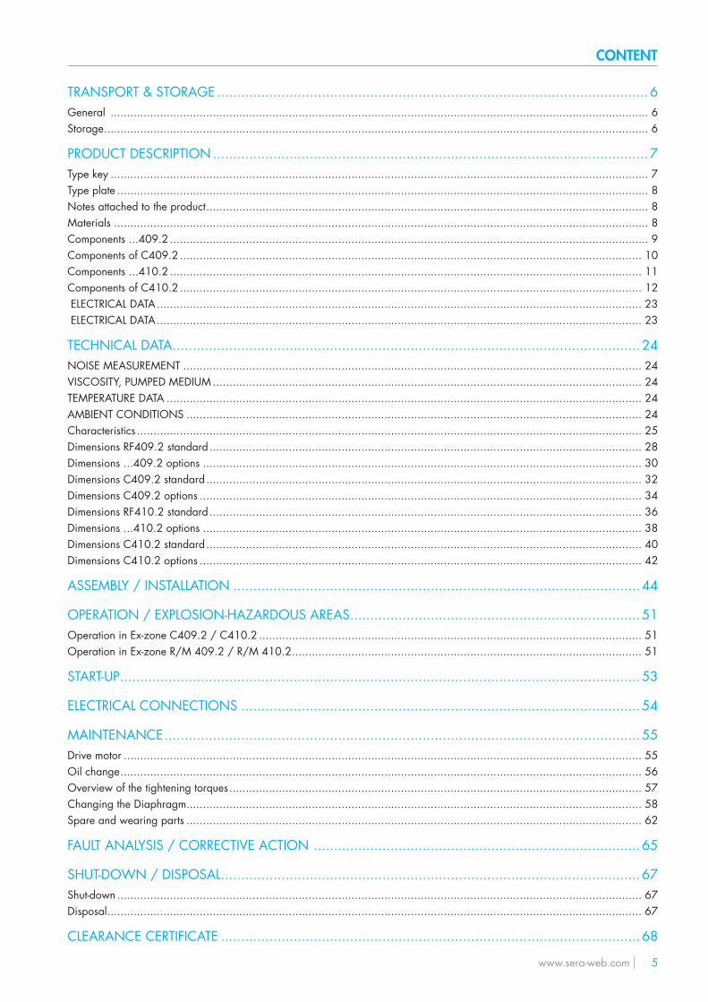
CONTENT
www.sera-web.com 5
TRANSPORT & STORAGE ...........................................................................................................6General ................................................................................................................................................................... 6Storage ..................................................................................................................................................................... 6
PRODUCT DESCRIPTION ............................................................................................................7Type key ................................................................................................................................................................... 7Type plate ................................................................................................................................................................. 8Notes attached to the product ...................................................................................................................................... 8Materials .................................................................................................................................................................. 8Components ...409.2 ................................................................................................................................................. 9Components of C409.2 ............................................................................................................................................ 10Components ...410.2 ............................................................................................................................................... 11Components of C410.2 ............................................................................................................................................ 12 ELECTRICAL DATA ................................................................................................................................................... 23 ELECTRICAL DATA ................................................................................................................................................... 23
TECHNICAL DATA ....................................................................................................................24NOISE MEASUREMENT ........................................................................................................................................... 24VISCOSITY, PUMPED MEDIUM .................................................................................................................................. 24TEMPERATURE DATA ................................................................................................................................................ 24AMBIENT CONDITIONS .......................................................................................................................................... 24Characteristics ......................................................................................................................................................... 25Dimensions RF409.2 standard ................................................................................................................................... 28Dimensions ...409.2 options ..................................................................................................................................... 30Dimensions C409.2 standard .................................................................................................................................... 32Dimensions C409.2 options ...................................................................................................................................... 34Dimensions RF410.2 standard ................................................................................................................................... 36Dimensions ...410.2 options ..................................................................................................................................... 38Dimensions C410.2 standard .................................................................................................................................... 40Dimensions C410.2 options ...................................................................................................................................... 42
ASSEMBLY / INSTALLATION .....................................................................................................44
OPERATION / EXPLOSION-HAZARDOUS AREAS ........................................................................51Operation in Ex-zone C409.2 / C410.2 .................................................................................................................... 51Operation in Ex-zone R/M 409.2 / R/M 410.2 .......................................................................................................... 51
START-UP .................................................................................................................................53
ELECTRICAL CONNECTIONS ...................................................................................................54
MAINTENANCE ......................................................................................................................55Drive motor ............................................................................................................................................................. 55Oil change .............................................................................................................................................................. 56Overview of the tightening torques ............................................................................................................................. 57Changing the Diaphragm .......................................................................................................................................... 58Spare and wearing parts .......................................................................................................................................... 62
FAULT ANALYSIS / CORRECTIVE ACTION .................................................................................65
SHUT-DOWN / DISPOSAL ........................................................................................................67Shut-down ............................................................................................................................................................... 67Disposal .................................................................................................................................................................. 67
CLEARANCE CERTIFICATE ........................................................................................................68
6 www.sera-web.com
TRANSPORT & STORAGE
General
sera products are checked for perfect condition and function previous to shipment.Check for transport damage immediately after arrival of goods. If damage is found, this is to be reported immediately to the responsible carrier and the manufacturer.
Storage
An undamaged packaging protects the unit during storage and should only be opened when the product is installed.Proper storage increases the service life of the product and includes prevention of negative influences such as heat, moisture, dust, chemicals etc.
The following storage specifications are to be obsered:
■ Storage place: cool, dry, dustfree and slightly ventilated ■ Storage temperature and relative air humidity see Chapter „TECHNICAL DATA“. ■ The maximum storage time for the standard packaging is 12 months.
If these values are exceeded, metal products should be sealed in foil and protected from condensation water with a suitable desiccant.
Do not store solvents, fuels, lubricants, chemicals, acids, disinfectants and similar in the storage room.
WARNING
Observe and follow the safety instructions by all means.See the additional instructions „SAFETY INSTRUCTIONS“.Man, machine and environment are endangered if the safety instructions are not observed.
SI01
PRODUCT DESCRIPTION
www.sera-web.com 7
PRODUCT DESCRIPTION
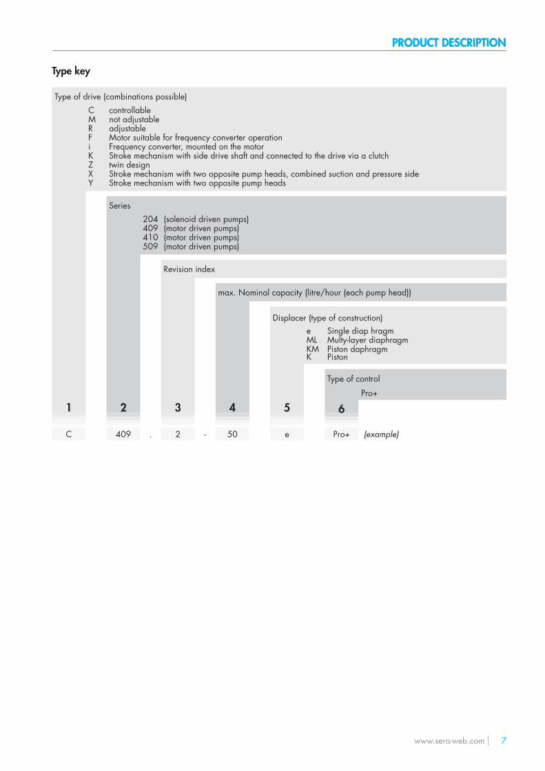
Type key
Type of drive (combinations possible)C controllableM not adjustableR adjustableF Motor suitable for frequency converter operationi Frequency converter, mounted on the motorK Stroke mechanism with side drive shaft and connected to the drive via a clutchZ twin designX Stroke mechanism with two opposite pump heads, combined suction and pressure sideY Stroke mechanism with two opposite pump heads
Series204 (solenoid driven pumps)409 (motor driven pumps)410 (motor driven pumps)509 (motor driven pumps)
Revision index
max. Nominal capacity (litre/hour (each pump head))
Displacer (type of construction)e Single diap hragmML Multy-layer diaphragm
1 2 3 4 5
KM Piston daphragmK Piston
Type of control
6Pro+
C 409 . 2 - 50 e Pro+ (example)
PRODUCT DESCRIPTION
8 www.sera-web.com
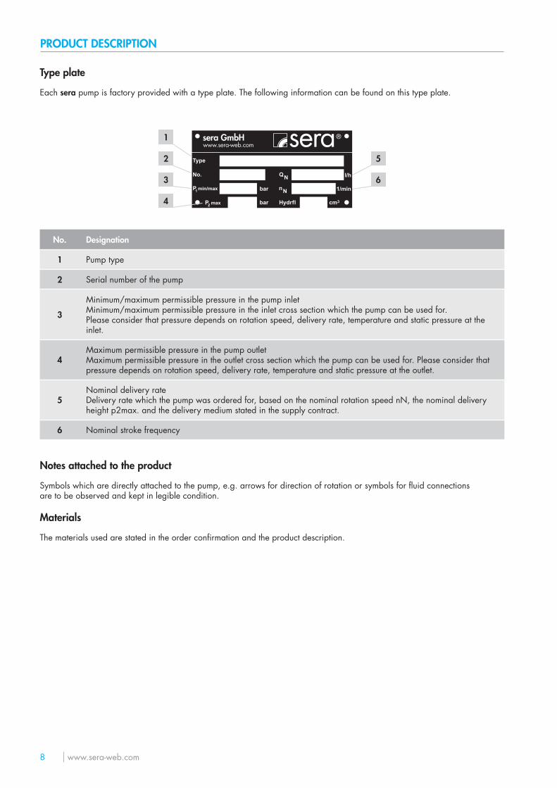
Type plate
Each sera pump is factory provided with a type plate. The following information can be found on this type plate.
Type
No.
P1 min/max
P2 max
bar
bar
nN
Hydrfl
QN l/h
1/min
cm3
1
2
3
4
5
6
No. Designation
1 Pump type
2 Serial number of the pump
3
Minimum/maximum permissible pressure in the pump inletMinimum/maximum permissible pressure in the inlet cross section which the pump can be used for.Please consider that pressure depends on rotation speed, delivery rate, temperature and static pressure at the inlet.
4Maximum permissible pressure in the pump outletMaximum permissible pressure in the outlet cross section which the pump can be used for. Please consider that pressure depends on rotation speed, delivery rate, temperature and static pressure at the outlet.
5Nominal delivery rateDelivery rate which the pump was ordered for, based on the nominal rotation speed nN, the nominal deliveryheight p2max. and the delivery medium stated in the supply contract.
6 Nominal stroke frequency
Notes attached to the product
Symbols which are directly attached to the pump, e.g. arrows for direction of rotation or symbols for fluid connectionsare to be observed and kept in legible condition.
Materials
The materials used are stated in the order confirmation and the product description.
PRODUCT DESCRIPTION
www.sera-web.com 9
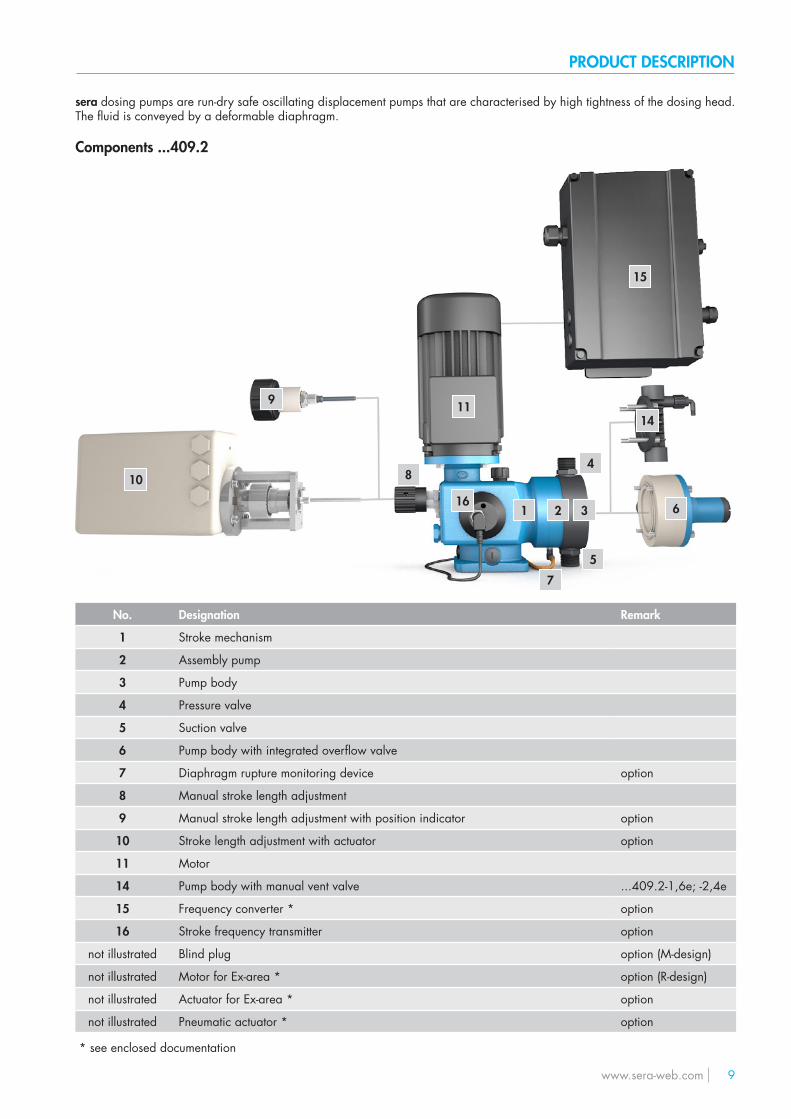
sera dosing pumps are run-dry safe oscillating displacement pumps that are characterised by high tightness of the dosing head. The fluid is conveyed by a deformable diaphragm.
Components ...409.2
4
3
5
2
15
16
7
1 6
9
10 8
1114
No. Designation Remark
1 Stroke mechanism
2 Assembly pump
3 Pump body
4 Pressure valve
5 Suction valve
6 Pump body with integrated overflow valve
7 Diaphragm rupture monitoring device option
8 Manual stroke length adjustment
9 Manual stroke length adjustment with position indicator option
10 Stroke length adjustment with actuator option
11 Motor
14 Pump body with manual vent valve ...409.2-1,6e; -2,4e
15 Frequency converter * option
16 Stroke frequency transmitter option
not illustrated Blind plug option (M-design)
not illustrated Motor for Ex-area * option (R-design)
not illustrated Actuator for Ex-area * option
not illustrated Pneumatic actuator * option
* see enclosed documentation
PRODUCT DESCRIPTION
10 www.sera-web.com
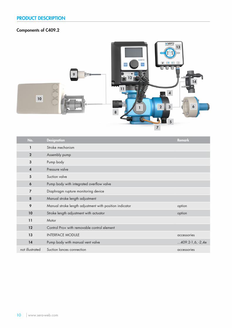
Components of C409.2
4
3
5
2
12
13
7
1 6
9
10
8
11
14
No. Designation Remark
1 Stroke mechanism
2 Assembly pump
3 Pump body
4 Pressure valve
5 Suction valve
6 Pump body with integrated overflow valve
7 Diaphragm rupture monitoring device
8 Manual stroke length adjustment
9 Manual stroke length adjustment with position indicator option
10 Stroke length adjustment with actuator option
11 Motor
12 Control Pro+ with removable control element
13 INTERFACE MODULE accessories
14 Pump body with manual vent valve ...409.2-1,6, -2,4e
not illustrated Suction lances connection accessories
PRODUCT DESCRIPTION
www.sera-web.com 11
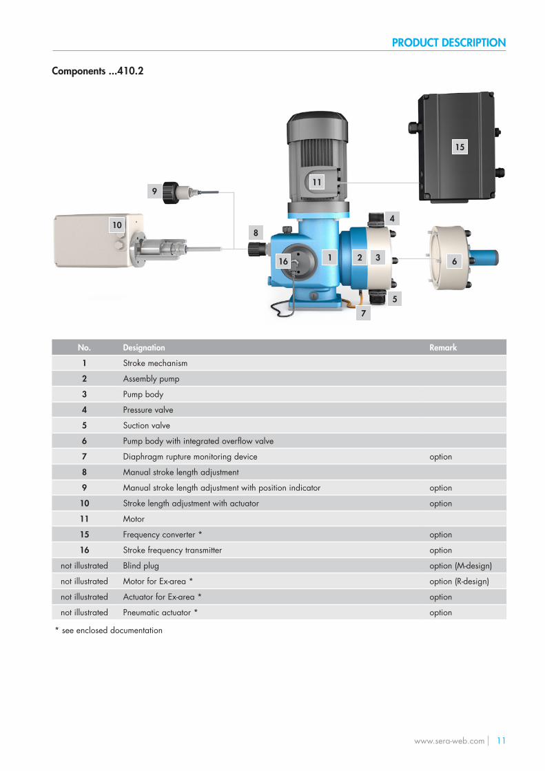
Components ...410.2
4
3
5
2
15
16
7
1 6
9
108
11
No. Designation Remark
1 Stroke mechanism
2 Assembly pump
3 Pump body
4 Pressure valve
5 Suction valve
6 Pump body with integrated overflow valve
7 Diaphragm rupture monitoring device option
8 Manual stroke length adjustment
9 Manual stroke length adjustment with position indicator option
10 Stroke length adjustment with actuator option
11 Motor
15 Frequency converter * option
16 Stroke frequency transmitter option
not illustrated Blind plug option (M-design)
not illustrated Motor for Ex-area * option (R-design)
not illustrated Actuator for Ex-area * option
not illustrated Pneumatic actuator * option
* see enclosed documentation
PRODUCT DESCRIPTION
12 www.sera-web.com
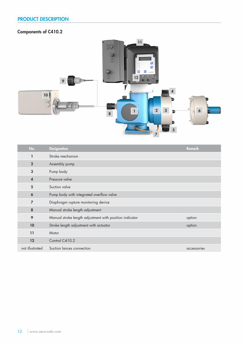
Components of C410.2
4
3
5
2
12
7
1 6
9
10
8
11
No. Designation Remark
1 Stroke mechanism
2 Assembly pump
3 Pump body
4 Pressure valve
5 Suction valve
6 Pump body with integrated overflow valve
7 Diaphragm rupture monitoring device
8 Manual stroke length adjustment
9 Manual stroke length adjustment with position indicator option
10 Stroke length adjustment with actuator option
11 Motor
12 Control C410.2
not illustrated Suction lances connection accessories
PRODUCT DESCRIPTION
www.sera-web.com 13
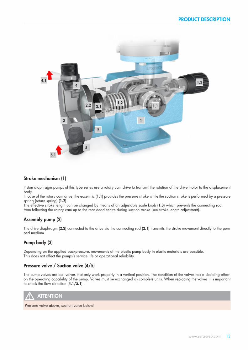
Stroke mechanism (1)
Piston diaphragm pumps of this type series use a rotary cam drive to transmit the rotation of the drive motor to the displacementbody.In case of the rotary cam drive, the eccentric (1.1) provides the pressure stroke while the suction stroke is performed by a pressurespring (return spring) (1.2).The effective stroke length can be changed by means of an adjustable scale knob (1.3) which prevents the connecting rodfrom following the rotary cam up to the rear dead centre during suction stroke (see stroke length adjustment).
Assembly pump (2)
The drive diaphragm (2.2) connected to the drive via the connecting rod (2.1) transmits the stroke movement directly to the pum-ped medium.
Pump body (3)
Depending on the applied backpressure, movements of the plastic pump body in elastic materials are possible.This does not affect the pumps’s service life or operational reliability.
Pressure valve / Suction valve (4/5)
The pump valves are ball valves that only work properly in a vertical position. The condition of the valves has a deciding effecton the operating capability of the pump. Valves must be exchanged as complete units. When replacing the valves it is important to check the flow direction (4.1/5.1) .
ATTENTION
Pressure valve above, suction valve below!
1
1.21.1
1.3
2
2.12.2
3
4
5
4.1
5.1
PRODUCT DESCRIPTION
14 www.sera-web.com
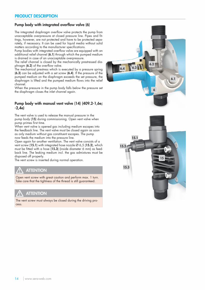
Pump body with integrated overflow valve (6)
The integrated diaphragm overflow valve protects the pump from unacceptable overpressure at closed pressure line. Pipes and fit-tings, however, are not protected and have to be protected sepa-rately, if necessary. It can be used for liquid media without solid matters according to the manufacturer specifications.Pump bodies with integrated overflow valve are equipped with an additional relief channel (6.1) through which the pumped medium is drained in case of an unacceptable overpressure.The relief channel is closed by the mechanically prestressed dia-phragm (6.2) of the overflow valve.The mechanical prestress which is executed by a pressure spring (6.3) can be adjusted with a set screw (6.4). If the pressure of the pumped medium on the diaphragm exceeds the set pressure, the diaphragm is lifted and the pumped medium flows into the relief channel.When the pressure in the pump body falls below the pressure set the diaphragm closes the inlet channel again.
Pump body with manual vent valve (14) (409.2-1,6e; -2,4e)
The vent valve is used to release the manual pressure in thepump body (15) during commissioning. Open vent valve whenpump primes first time.When vent valve is opened gas including medium escapes intothe feedback line. The vent valve must be closed again as soonas only medium without gas constituent escapes. The pumpnow feeds the medium into the pressure line.Open again for another ventilation. The vent valve consists of avent screw (15.1) with integrated hose nozzle Ø 6,5 (15.2), which must be fitted with a hose (15.3) (inside diameter 6 mm) as feed-back line. The leaking medium incl. the gas admixtures must be disposed off properly.The vent screw is inserted during normal operation.
ATTENTIONOpen vent screw with great caution and perform max. 1 turn. Take care that the tightness of the thread is still guaranteed.
ATTENTIONThe vent screw must always be closed during the driving pro-cess.
6
6.2
6.1
6.36.4
15
15.2
15.1
15.3
PRODUCT DESCRIPTION
www.sera-web.com 15
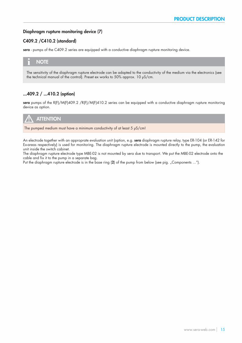
Diaphragm rupture monitoring device (7)
C409.2 /C410.2 (standard)
sera - pumps of the C409.2 series are equipped with a conductive diaphragm rupture monitoring device.
NOTE
The sensitivity of the diaphragm rupture electrode can be adapted to the conductivity of the medium via the electronics (see the technical manual of the control). Preset ex works to 50% approx. 10 μS/cm.
...409.2 / ...410.2 (option)
sera pumps of the R(F)/M(F)409.2 /R(F)/M(F)410.2 series can be equipped with a conductive diaphragm rupture monitoring device as option.
ATTENTION
The pumped medium must have a minimum conductivity of at least 5 μS/cm!
An electrode together with an approprate evaluation unit (option, e.g. sera diaphragm rupture relay, type ER-104 (or ER-142 for Ex-areas respectively) is used for monitoring. The diaphragm rupture electrode is mounted directly to the pump, the evaluation unit inside the switch cabinet.The diaphragm rupture electrode type MBE-02 is not mounted by sera due to transport. We put the MBE-02 electrode onto thecable and fix it to the pump in a separate bag.Put the diaphragm rupture electrode is in the base ring (2) of the pump from below (see pig. „Components ...“).
PRODUCT DESCRIPTION
16 www.sera-web.com
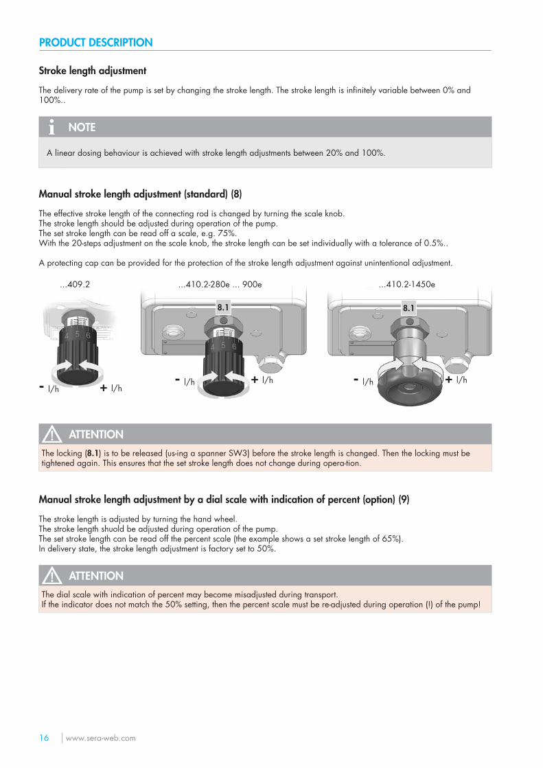
Stroke length adjustment
The delivery rate of the pump is set by changing the stroke length. The stroke length is infinitely variable between 0% and 100%..
NOTE
A linear dosing behaviour is achieved with stroke length adjustments between 20% and 100%.
Manual stroke length adjustment (standard) (8)
The effective stroke length of the connecting rod is changed by turning the scale knob.The stroke length should be adjusted during operation of the pump.The set stroke length can be read off a scale, e.g. 75%.With the 20-steps adjustment on the scale knob, the stroke length can be set individually with a tolerance of 0.5%..
A protecting cap can be provided for the protection of the stroke length adjustment against unintentional adjustment.
+ l/h- l/h+ l/h- l/h + l/h- l/h
...409.2 ...410.2-280e ... 900e ...410.2-1450e
8.18.1
ATTENTIONThe locking (8.1) is to be released (us-ing a spanner SW3) before the stroke length is changed. Then the locking must be tightened again. This ensures that the set stroke length does not change during opera-tion.
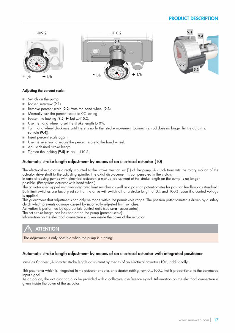
Manual stroke length adjustment by a dial scale with indication of percent (option) (9)
The stroke length is adjusted by turning the hand wheel.The stroke length shuold be adjusted during operation of the pump.The set stroke length can be read off the percent scale (the example shows a set stroke length of 65%).In delivery state, the stroke length adjustment is factory set to 50%.
ATTENTIONThe dial scale with indication of percent may become misadjusted during transport.If the indicator does not match the 50% setting, then the percent scale must be re-adjusted during operation (!) of the pump!
PRODUCT DESCRIPTION
www.sera-web.com 17
9.2
9.1
9.3
9.4
+ l/h- l/h+ l/h- l/h
...409.2 ...410.2
9.5
Adjusting the percent scale:
■ Switch on the pump. ■ Loosen setscrew (9.1). ■ Remove percent scale (9.2) from the hand wheel (9.3). ■ Manually turn the percent scale to 0% setting. ■ Loosen the locking (9.5) ► bei ...410.2. ■ Use the hand wheel to set the stroke length to 0%. ■ Turn hand wheel clockwise until there is no further stroke movement (connecting rod does no longer hit the adjusting
spindle (9.4)). ■ Insert percent scale again. ■ Use the setscrew to secure the percent scale to the hand wheel. ■ Adjust desired stroke length. ■ Tighten the locking (9.5) ► bei ...410.2.
Automatic stroke length adjustment by means of an electrical actuator (10)
The electrical actuator is directly mounted to the stroke mechanism (1) of the pump. A clutch transmits the rotary motion of the actuator drive shaft to the adjusting spindle. The axial displacement is compensated in the clutch.In case of dosing pumps with electrical actuator, a manual adjustment of the stroke length on the pump is no longerpossible. (Exception: actuator with hand wheel)The actuator is equipped with two integrated limit switches as well as a position potentiometer for position feedback as standard.Both limit switches are factory set so that the drive will switch off at a stroke length of 0% and 100%, even if a control voltage is applied.This guarantees that adjustments can only be made within the permissible range. The position potentiometer is driven by a safety clutch which prevents damage caused by incorrectly adjusted limit switches.Activation is performed by appropriate control units (see sera - accessories).The set stroke length can be read off on the pump (percent scale).Information on the electrical connection is given inside the cover of the actuator.
ATTENTION
The adjustment is only possible when the pump is running!
Automatic stroke length adjustment by means of an electrical actuator with integrated positioner
same as Chapter „Automatic stroke length adjustment by means of an electrical actuator (10)“, additionally:
This positioner which is integrated in the actuator enables an actuator setting from 0…100% that is proportional to the connected input signal.As an option, the actuator can also be provided with a collective interference signal. Information on the electrical connection is given inside the cover of the actuator.
TECHNICAL DATA
18 www.sera-web.com
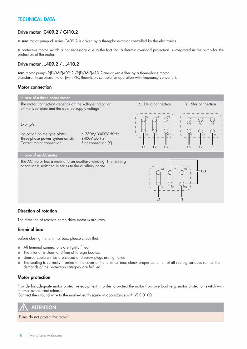
Drive motor C409.2 / C410.2
A sera motor pump of series C409.2 is driven by a threephase-motor controlled by the electronics.
A protective motor switch is not necessary due to the fact that a thermic overload protection is integrated in the pump for the protection of the motor.
Drive motor ...409.2 / ...410.2
sera motor pumps R(F)/M(F)409.2 /R(F)/M(F)410.2 are driven either by a three-phase motor.Standard: three-phase motor (with PTC thermistor; suitable for operation with frequency converter).
Motor connection
In case of a three-phase motor
The motor connection depends on the voltage indicationon the type plate and the applied supply voltage.
∆ Delta connection Y Star connection
L1 L2 L3
W2 U2 V2
U1 V1 W1
L1 L2 L3
W2 U2 V2
U1 V1 W1
Example:
Indication on the type plate:Three-phase power system on sit:Correct motor connection:
∆ 230V/ Y400V 50HzY400V 50 HzStar connection (Y)
In case of an AC motor
The AC motor has a main and an auxiliary winding. The running capacitor is switched in series to the auxiliary phase.
L1 N
W2 U2 V2
U1 V1 W1
CB
Direction of rotation
The direction of rotation of the drive motor is arbitrary.
Terminal box
Before closing the terminal box, please check that:
■ All terminal connections are tightly fitted. ■ The interior is clean and free of foreign bodies. ■ Unused cable entries are closed and screw plugs are tightened. ■ The sealing is correctly inserted in the cover of the terminal box; check proper condition of all sealing surfaces so that the
demands of the protection category are fulfilled.
Motor protection
Provide for adequate motor protective equipment in order to protect the motor from overload (e.g. motor protection switch with thermal overcurrent release).Connect the ground wire to the marked earth screw in accordance with VDE 0100.
ATTENTION
Fuses do not protect the motor!
PRODUCT DESCRIPTION
www.sera-web.com 19
Conrol C409.2 Pro+/ C410.2 (12)
Among other things, the control enable the proportional dosing via analogue signals 4 … 20 mA or contact signals with the possibility of pulse division or pulse multiplication.The graphical display shows information about the current status of the pump.A connection for flow monitoring or flow rate measurement and an „empty“ signal with pre-alarm and dry run alarm are avai-lable as standard.
INTERFACE MODULE (13) (accessories C409.2)
The INTERFACE MODULE provides level input, PROFIBUS connectivity (see TM05) and PROFINET connectivity (see TM07).
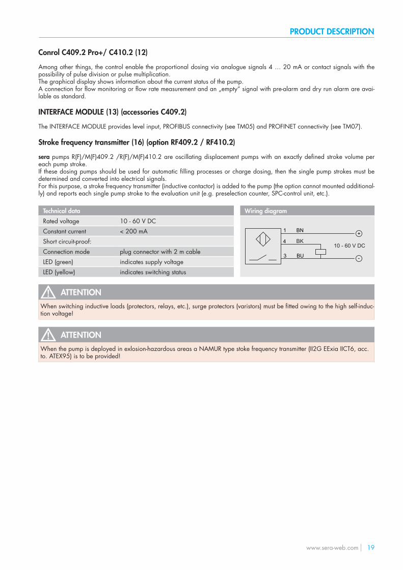
Stroke frequency transmitter (16) (option RF409.2 / RF410.2)
sera pumps R(F)/M(F)409.2 /R(F)/M(F)410.2 are oscillating displacement pumps with an exactly defined stroke volume per each pump stroke.If these dosing pumps should be used for automatic filling processes or charge dosing, then the single pump strokes must be determined and converted into electrical signals.For this purpose, a stroke frequency transmitter (inductive contactor) is added to the pump (the option cannot mounted additional-ly) and reports each single pump stroke to the evaluation unit (e.g. preselection counter, SPC-control unit, etc.).
Technical data Wiring diagram
Rated voltage 10 - 60 V DC +
-
1 BN
4
schwarz 3 BU V
10 - 60 V DCBK
Constant current < 200 mAShort circuit-proof:Connection mode plug connector with 2 m cableLED (green) indicates supply voltageLED (yellow) indicates switching status
ATTENTIONWhen switching inductive loads (protectors, relays, etc.), surge protectors (varistors) must be fitted owing to the high self-induc-tion voltage!
ATTENTIONWhen the pump is deployed in exlosion-hazardous areas a NAMUR type stoke frequency transmitter (II2G EExia IICT6, acc.to. ATEX95) is to be provided!
TECHNICAL DATA
20 www.sera-web.com
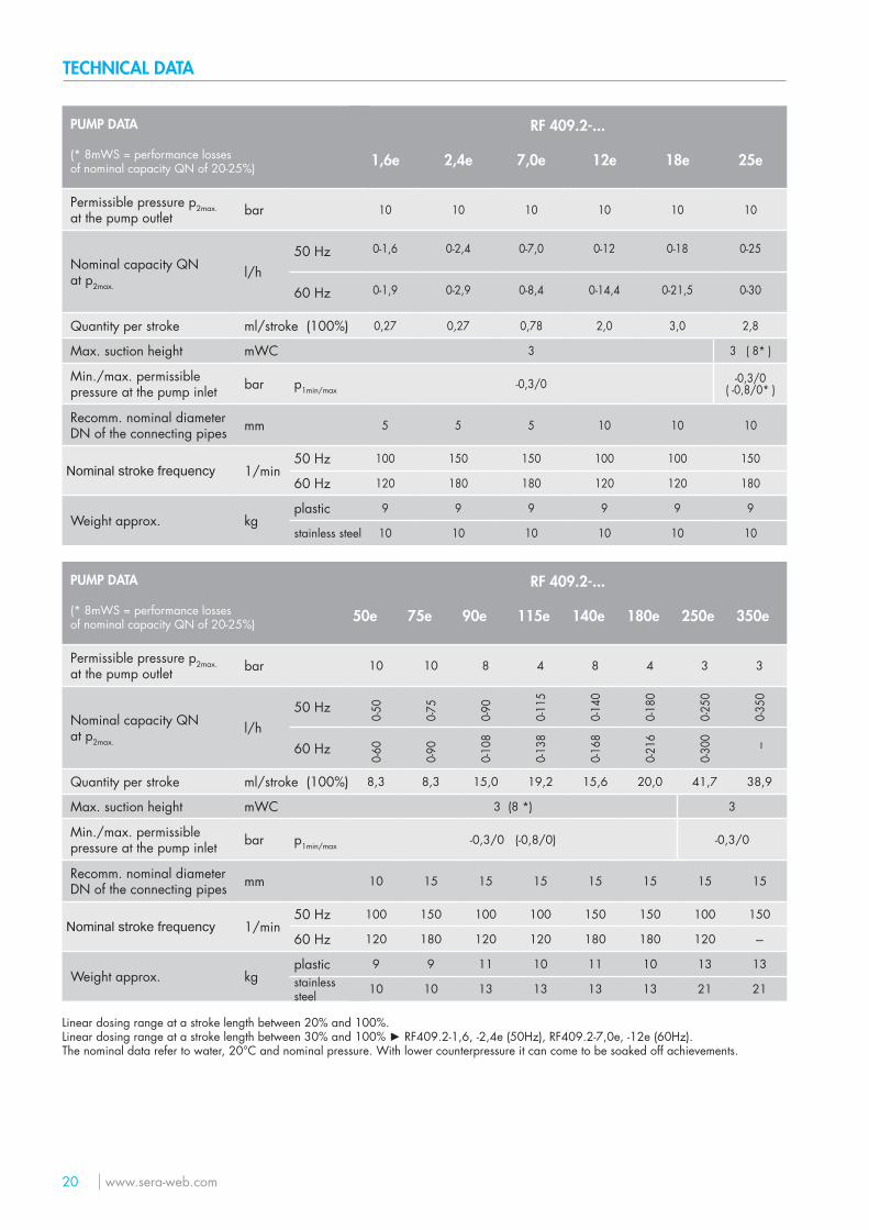
PUMP DATA
(* 8mWS = performance losses of nominal capacity QN of 20-25%)
Permissible pressure p2max.at the pump outlet bar
Nominal capacity QNat p2max.
l/h50 Hz
60 Hz
Quantity per stroke ml/stroke (100%)
Max. suction height mWC
Min./max. permissible pressure at the pump inlet bar p1min/max
Recomm. nominal diameter DN of the connecting pipes mm
Nominal stroke frequency 1/min50 Hz
60 Hz
Weight approx. kgplasticstainless steel
RF 409.2-...
1,6e 2,4e 7,0e 12e 18e 25e
10 10 10 10 10 10
0-1,6 0-2,4 0-7,0 0-12 0-18 0-25
0-1,9 0-2,9 0-8,4 0-14,4 0-21,5 0-30
0,27 0,27 0,78 2,0 3,0 2,8
3 3 ( 8* )
-0,3/0 -0,3/0 ( -0,8/0* )
5 5 5 10 10 10
100 150 150 100 100 150
120 180 180 120 120 180
9 9 9 9 9 9
10 10 10 10 10 10
PUMP DATA
(* 8mWS = performance losses of nominal capacity QN of 20-25%)
Permissible pressure p2max.at the pump outlet bar
Nominal capacity QNat p2max.
l/h50 Hz
60 Hz
Quantity per stroke ml/stroke (100%)
Max. suction height mWC
Min./max. permissible pressure at the pump inlet bar p1min/max
Recomm. nominal diameter DN of the connecting pipes mm
Nominal stroke frequency 1/min50 Hz
60 Hz
Weight approx. kgplastic
stainless steel
RF 409.2-...
50e 75e 90e 115e 140e 180e 250e 350e
10 10 8 4 8 4 3 3
0-50
0-75
0-90
0-11
5
0-14
0
0-18
0
0-25
0
0-35
0
0-60
0-90
0-10
8
0-13
8
0-16
8
0-21
6
0-30
0 ---
8,3 8,3 15,0 19,2 15,6 20,0 41,7 38,9
3 (8 *) 3
-0,3/0 (-0,8/0) -0,3/0
10 15 15 15 15 15 15 15
100 150 100 100 150 150 100 150
120 180 120 120 180 180 120 ---
9 9 11 10 11 10 13 13
10 10 13 13 13 13 21 21
Linear dosing range at a stroke length between 20% and 100%.Linear dosing range at a stroke length between 30% and 100% ► RF409.2-1,6, -2,4e (50Hz), RF409.2-7,0e, -12e (60Hz).The nominal data refer to water, 20°C and nominal pressure. With lower counterpressure it can come to be soaked off achievements.
TECHNICAL DATA
www.sera-web.com 21
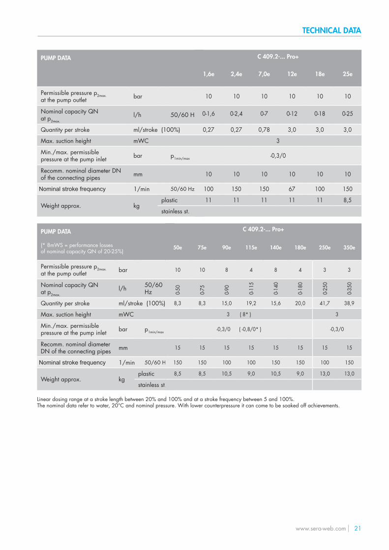
PUMP DATA
(* 8mWS = performance losses of nominal capacity QN of 20-25%)
Permissible pressure p2max.at the pump outlet bar
Nominal capacity QNat p2max.
l/h 50/60 Hz
Quantity per stroke ml/stroke (100%)
Max. suction height mWC
Min./max. permissible pressure at the pump inlet bar p1min/max
Recomm. nominal diameter DN of the connecting pipes mm
Nominal stroke frequency 1/min 50/60 Hz
Weight approx. kgplastic
stainless st.
PUMP DATA
Permissible pressure p2max.at the pump outlet bar
Nominal capacity QNat p2max.
l/h 50/60 Hz
Quantity per stroke ml/stroke (100%)
Max. suction height mWC
Min./max. permissible pressure at the pump inlet bar p1min/max
Recomm. nominal diameter DN of the connecting pipes mm
Nominal stroke frequency 1/min 50/60 Hz
Weight approx. kgplastic
stainless st.
C 409.2-... Pro+
1,6e 2,4e 7,0e 12e 18e 25e
10 10 10 10 10 10
0-1,6 0-2,4 0-7 0-12 0-18 0-25
0,27 0,27 0,78 3,0 3,0 3,0
3
-0,3/0
10 10 10 10 10 10
100 150 150 67 100 150
11 11 11 11 11 8,5
C 409.2-... Pro+
50e 75e 90e 115e 140e 180e 250e 350e
10 10 8 4 8 4 3 3
0-50
0-75
0-90
0-11
5
0-14
0
0-18
0
0-25
0
0-35
0
8,3 8,3 15,0 19,2 15,6 20,0 41,7 38,9
3 ( 8* ) 3
-0,3/0 ( -0,8/0* ) -0,3/0
15 15 15 15 15 15 15 15
150 150 100 100 150 150 100 150
8,5 8,5 10,5 9,0 10,5 9,0 13,0 13,0
Linear dosing range at a stroke length between 20% and 100% and at a stroke frequency between 5 and 100%.The nominal data refer to water, 20°C and nominal pressure. With lower counterpressure it can come to be soaked off achievements.
TECHNICAL DATA
22 www.sera-web.com
PUMP DATA
Permissible pressure p2max.at the pump outlet bar
Nominal capacity QNat p2max.
l/h50 Hz
60 Hz
Quantity per stroke ml/stroke (100%)
Max. suction height mWC
Min./max. permissible pressure at the pump inlet bar p1min/max
Recommended nominal diameter DN of the connecting pipes mm
Nominal stroke frequency 1/min50 Hz
60 Hz
Weight approx. kgplastic
stainless steel
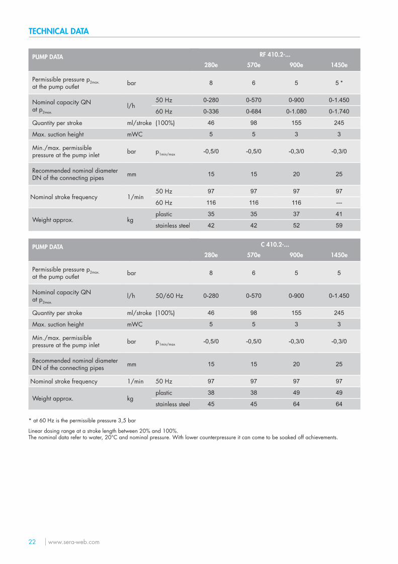
RF 410.2-...
280e 570e 900e 1450e
8 6 5 5 *
0-280 0-570 0-900 0-1.450
0-336 0-684 0-1.080 0-1.740
46 98 155 245
5 5 3 3
-0,5/0 -0,5/0 -0,3/0 -0,3/0
15 15 20 25
97 97 97 97
116 116 116 ---
35 35 37 41
42 42 52 59
Linear dosing range at a stroke length between 20% and 100%.The nominal data refer to water, 20°C and nominal pressure. With lower counterpressure it can come to be soaked off achievements.
PUMP DATA
Permissible pressure p2max.at the pump outlet bar
Nominal capacity QNat p2max.
l/h 50/60 Hz
Quantity per stroke ml/stroke (100%)
Max. suction height mWC
Min./max. permissible pressure at the pump inlet bar p1min/max
Recommended nominal diameter DN of the connecting pipes mm
Nominal stroke frequency 1/min 50 Hz
Weight approx. kgplastic
stainless steel
C 410.2-...
280e 570e 900e 1450e
8 6 5 5
0-280 0-570 0-900 0-1.450
46 98 155 245
5 5 3 3
-0,5/0 -0,5/0 -0,3/0 -0,3/0
15 15 20 25
97 97 97 97
38 38 49 49
45 45 64 64
* at 60 Hz is the permissible pressure 3,5 bar
TECHNICAL DATA
www.sera-web.com 23
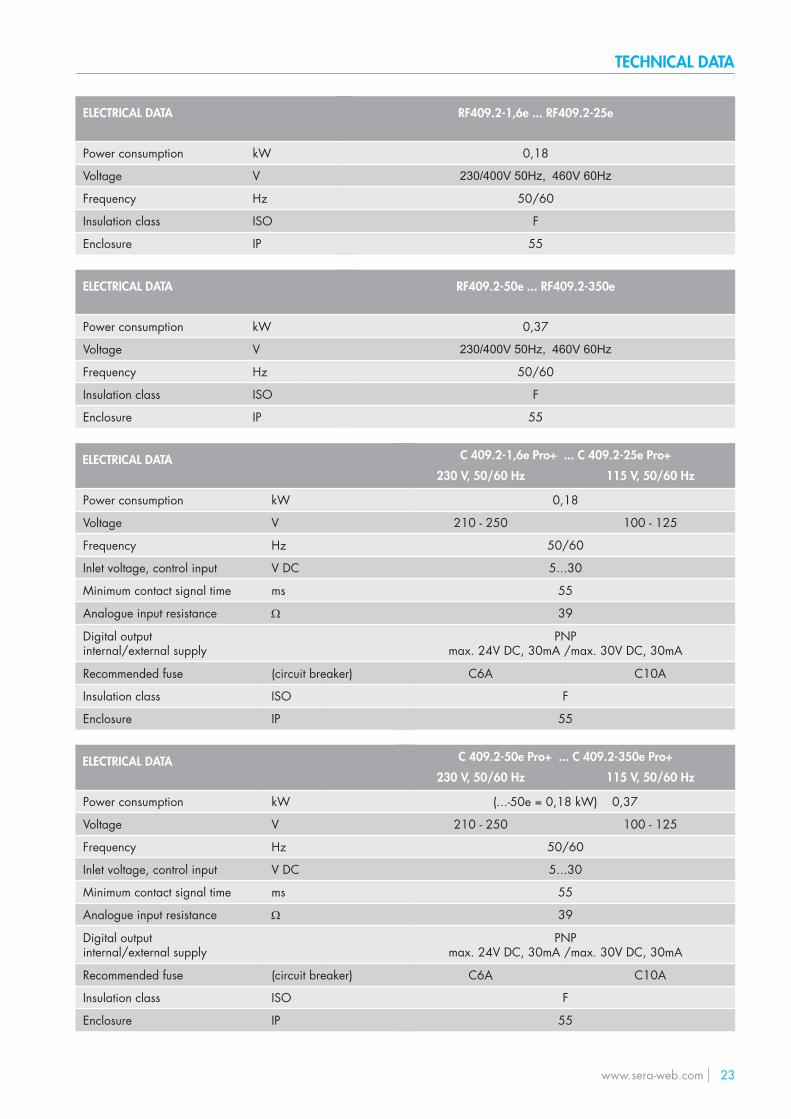
C 409.2-50e Pro+ ... C 409.2-350e Pro+
230 V, 50/60 Hz 115 V, 50/60 Hz
(...-50e = 0,18 kW) 0,37
210 - 250 100 - 125
50/60
5...30
55
39
PNPmax. 24V DC, 30mA /max. 30V DC, 30mA
C6A C10A
F
55
ELECTRICAL DATA
Power consumption kW
Voltage V
Frequency Hz
Inlet voltage, control input V DC
Minimum contact signal time ms
Analogue input resistance Ω
Digital outputinternal/external supply
Recommended fuse (circuit breaker)
Insulation class ISO
Enclosure IP
ELECTRICAL DATA
Power consumption kW
Voltage V
Frequency Hz
Insulation class ISO
Enclosure IP
RF409.2-1,6e ... RF409.2-25e
0,18
230/400V 50Hz, 460V 60Hz
50/60
F
55
RF409.2-50e ... RF409.2-350e
0,37
230/400V 50Hz, 460V 60Hz
50/60
F
55
ELECTRICAL DATA
Power consumption kW
Voltage V
Frequency Hz
Insulation class ISO
Enclosure IP
C 409.2-1,6e Pro+ ... C 409.2-25e Pro+
230 V, 50/60 Hz 115 V, 50/60 Hz
0,18
210 - 250 100 - 125
50/60
5...30
55
39
PNPmax. 24V DC, 30mA /max. 30V DC, 30mA
C6A C10A
F
55
ELECTRICAL DATA
Power consumption kW
Voltage V
Frequency Hz
Inlet voltage, control input V DC
Minimum contact signal time ms
Analogue input resistance Ω
Digital outputinternal/external supply
Recommended fuse (circuit breaker)
Insulation class ISO
Enclosure IP
TECHNICAL DATA
24 www.sera-web.com
NOTE
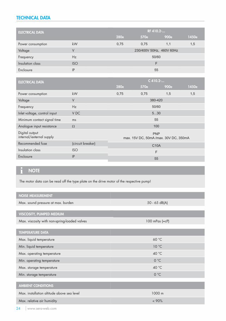
The motor data can be read off the type plate on the drive motor of the respective pump!
60 °C
10 °C
40 °C
0 °C
40 °C
0 °C
1000 m
< 90%
AMBIENT CONDITIONS
Max. installation altitude above sea level
Max. relative air humidity
100 mPas (=cP)
NOISE MEASUREMENT
Max. sound pressure at max. burden 50 - 65 dB(A)
TEMPERATURE DATA
Max. liquid temperature
Min. liquid temperature
Max. operating temperature
Min. operating temperature
Max. storage temperature
Min. storage temperature
VISCOSITY, PUMPED MEDIUM
Max. viscosity with non-spring-loaded valves
ELECTRICAL DATA
Power consumption kW
Voltage V
Frequency Hz
Inlet voltage, control input V DC
Minimum contact signal time ms
Analogue input resistance Ω
Digital outputinternal/external supply
Recommended fuse (circuit breaker)
Insulation class ISO
Enclosure IP
C 410.2-...
280e 570e 900e 1450e
0,75 0,75 1,5 1,5
380-420
50/60
5...30
55
100
PNPmax. 15V DC, 50mA /max. 30V DC, 350mA
C10A
F
55
ELECTRICAL DATA
Power consumption kW
Voltage V
Frequency Hz
Insulation class ISO
Enclosure IP
RF 410.2-...
280e 570e 900e 1450e
0,75 0,75 1,1 1,5
230/400V 50Hz, 460V 60Hz
50/60
F
55
TECHNICAL DATA
www.sera-web.com 25
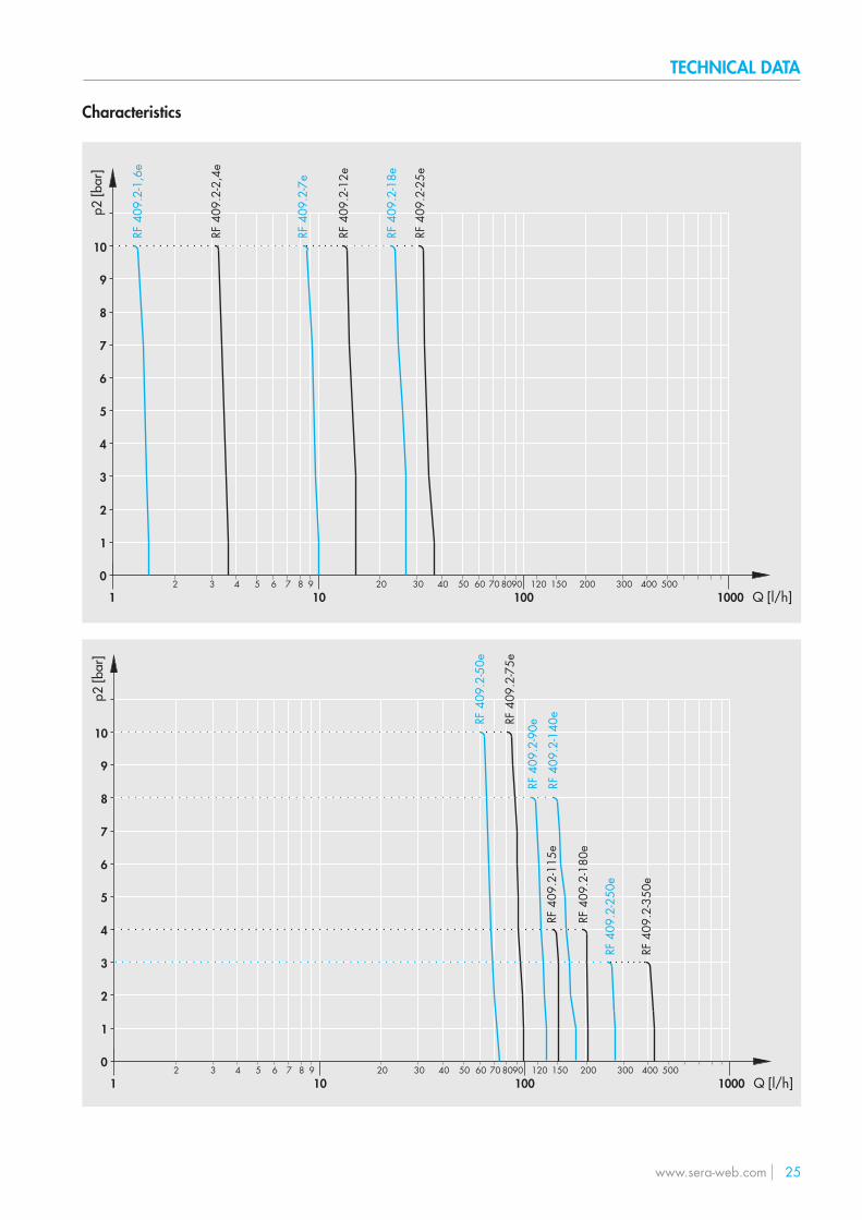
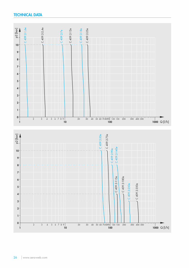
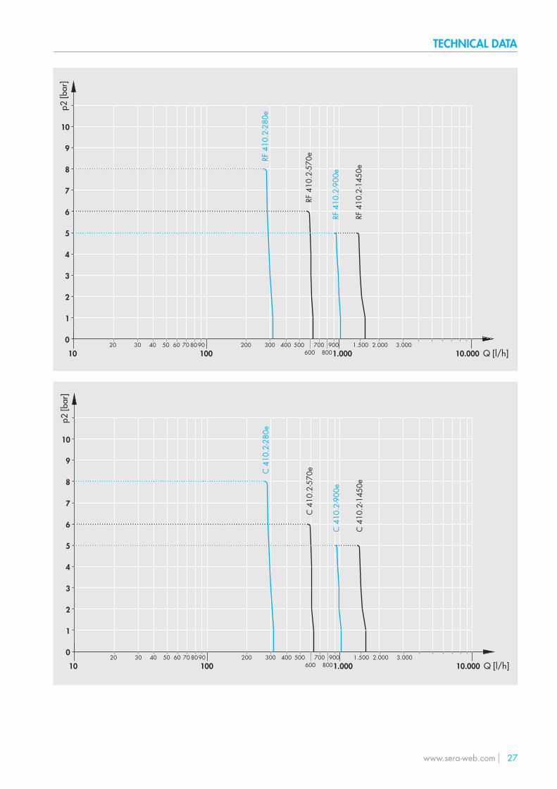
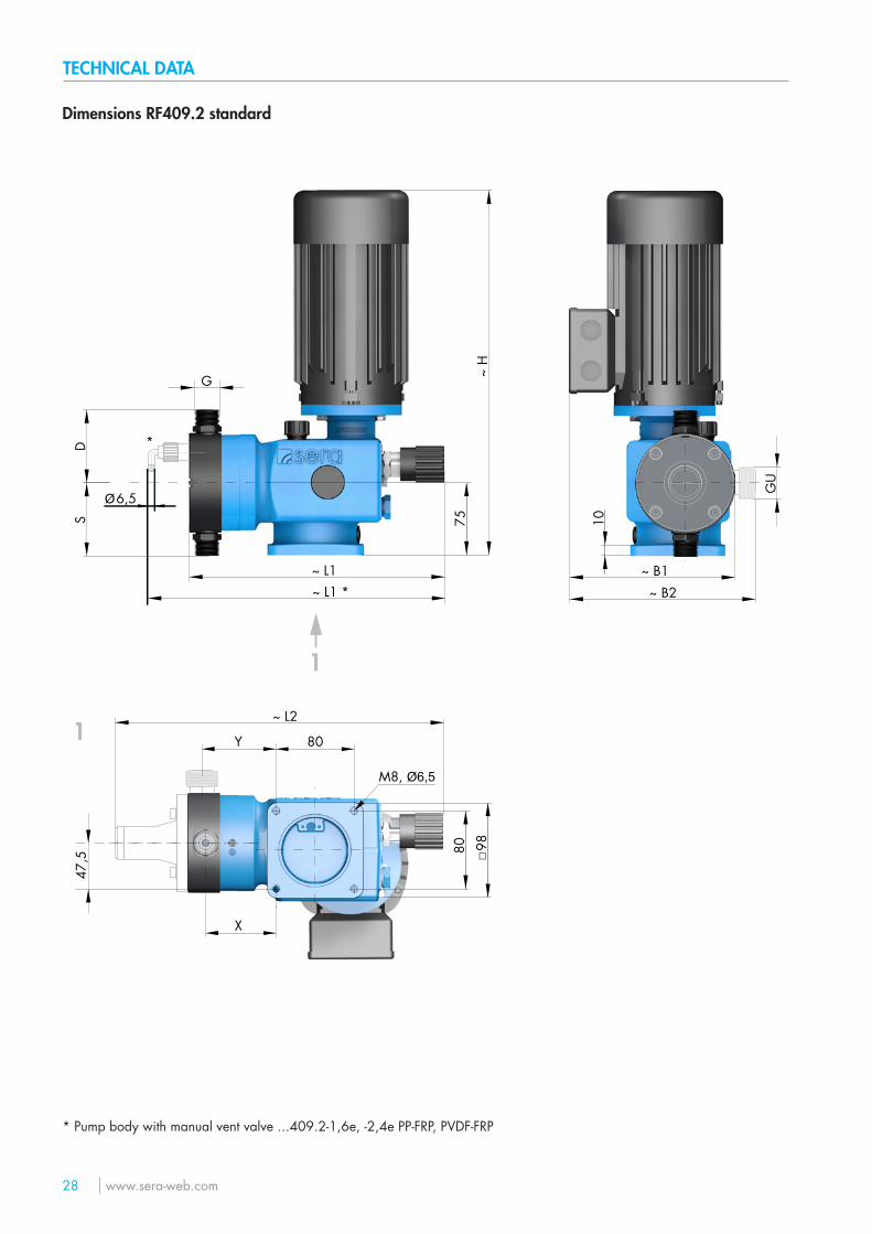
Characteristics
0
1
2
3
4
5
6
7
8
9
10
12 3 4 5 6 7 8 9 20 30 40 50 60 70 8090 200150 300 400 500
10 100 1000120
RF 4
09.2
-7e
RF 4
09.2
-1,6
e
RF 4
09.2
-12e
RF 4
09.2
-2,4
e
RF 4
09.2
-18e
RF 4
09.2
-25e
Q [l/h]
p2 [b
ar]
0
1
2
3
4
5
6
7
8
9
10
12 3 4 5 6 7 8 9 20 30 40 50 60 70 8090 200150 300 400 500
10 100 1000120
RF 4
09.2
-50e
RF 4
09.2
-75e
RF 4
09.2
-90e
RF 4
09.2
-140
e
RF 4
09.2
-180
e
RF 4
09.2
-115
e
RF 4
09.2
-250
e
RF 4
09.2
-350
e
Q [l/h]
p2 [b
ar]
TECHNICAL DATA
26 www.sera-web.com
0
1
2
3
4
5
6
7
8
9
10
12 3 4 5 6 7 8 9 20 30 40 50 60 70 8090 200150 300 400 500
10 100 1000120
C 4
09.2
-50e
C 4
09.2
-75e
C 4
09.2
-90e
C 4
09.2
-140
e
C 4
09.2
-180
e
C 4
09.2
-115
e
C 4
09.2
-250
e
C 4
09.2
-350
e
Q [l/h]
p2 [b
ar]
0
1
2
3
4
5
6
7
8
9
10
12 3 4 5 6 7 8 9 20 30 40 50 60 70 8090 200150 300 400 500
10 100 1000120
C 4
09.2
-7e
C 4
09.2
-1,6
e
C 4
09.2
-12e
C 4
09.2
-2,4
e
C 4
09.2
-18e
C 4
09.2
-25e
Q [l/h]
p2 [b
ar]
TECHNICAL DATA
www.sera-web.com 27
0
1
2
3
4
5
6
7
8
9
10
1020 30 40 50 60 70 8090 200 300 400 500
600700
800900 2.0001.500 3.000
100 1.000 10.000
RF 4
10.2
-280
e
RF 4
10.2
-570
e
RF 4
10.2
-900
e
RF 4
10.2
-145
0eQ [l/h]
p2 [b
ar]
0
1
2
3
4
5
6
7
8
9
10
1020 30 40 50 60 70 8090 200 300 400 500
600700
800900 2.0001.500 3.000
100 1.000 10.000
C 4
10.2
-280
e
C 4
10.2
-570
e
C 4
10.2
-900
e
C 4
10.2
-145
0e
Q [l/h]
p2 [b
ar]
TECHNICAL DATA
28 www.sera-web.com
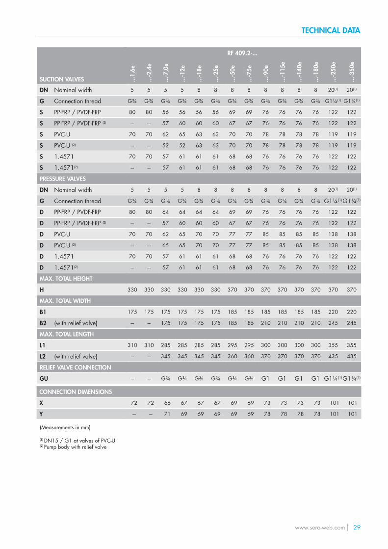
Dimensions RF409.2 standard
75
~ H
~ L2
~ L1 ~ B1~ B2
98
~ L1 *10
DS
G
GU
80
□
Y
47,5
X
80*
1
1
M8, Ø6,5
6,5Ø
* Pump body with manual vent valve ...409.2-1,6e, -2,4e PP-FRP, PVDF-FRP
TECHNICAL DATA
www.sera-web.com 29
RF 409.2-...
...1,
6e
...-2
,4e
...-7
,0e
...-1
2e
...-1
8e
...-2
5e
...-5
0e
...-7
5e
...-9
0e
...-1
15e
...-1
40e
...-1
80e
...-2
50e
...-3
50e
5 5 5 5 8 8 8 8 8 8 8 8 20(1) 20(1)
G¾ G¾ G¾ G¾ G¾ G¾ G¾ G¾ G¾ G¾ G¾ G¾ G1¼(1) G1¼(1)
80 80 56 56 56 56 69 69 76 76 76 76 122 122
--- --- 57 60 60 60 67 67 76 76 76 76 122 122
70 70 62 65 63 63 70 70 78 78 78 78 119 119
--- --- 52 52 63 63 70 70 78 78 78 78 119 119
70 70 57 61 61 61 68 68 76 76 76 76 122 122
--- --- 57 61 61 61 68 68 76 76 76 76 122 122
5 5 5 5 8 8 8 8 8 8 8 8 20(1) 20(1)
G¾ G¾ G¾ G¾ G¾ G¾ G¾ G¾ G¾ G¾ G¾ G¾ G1¼(1)G1¼(1)
80 80 64 64 64 64 69 69 76 76 76 76 122 122
--- --- 57 60 60 60 67 67 76 76 76 76 122 122
70 70 62 65 70 70 77 77 85 85 85 85 138 138
--- --- 65 65 70 70 77 77 85 85 85 85 138 138
70 70 57 61 61 61 68 68 76 76 76 76 122 122
--- --- 57 61 61 61 68 68 76 76 76 76 122 122
330 330 330 330 330 330 370 370 370 370 370 370 370 370
175 175 175 175 175 175 185 185 185 185 185 185 220 220
--- --- 175 175 175 175 185 185 210 210 210 210 245 245
310 310 285 285 285 285 295 295 300 300 300 300 355 355
--- --- 345 345 345 345 360 360 370 370 370 370 435 435
--- --- G¾ G¾ G¾ G¾ G¾ G¾ G1 G1 G1 G1 G1¼(1)G1¼(1)
CONNECTION DIMENSIONS
X
Y
72 72 66 67 67 67 69 69 73 73 73 73 101 101
--- --- 71 69 69 69 69 69 78 78 78 78 101 101
SUCTION VALVES
DN Nominal width
G Connection thread
S PP-FRP / PVDF-FRP
S PP-FRP / PVDF-FRP (2)
S PVC-U
S PVC-U (2)
S 1.4571
S 1.4571(2)
PRESSURE VALVES
DN Nominal width
G Connection thread
D PP-FRP / PVDF-FRP
D PP-FRP / PVDF-FRP (2)
D PVC-U
D PVC-U (2)
D 1.4571
D 1.4571(2)
MAX. TOTAL HEIGHT
H
MAX. TOTAL WIDTH
B1
B2 (with relief valve)
MAX. TOTAL LENGTH
L1
L2 (with relief valve)
RELIEF VALVE CONNECTION
GU
(Measurements in mm)
(1) DN15 / G1 at valves of PVC-U(2) Pump body with relief valve
TECHNICAL DATA
30 www.sera-web.com
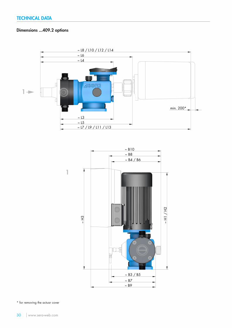
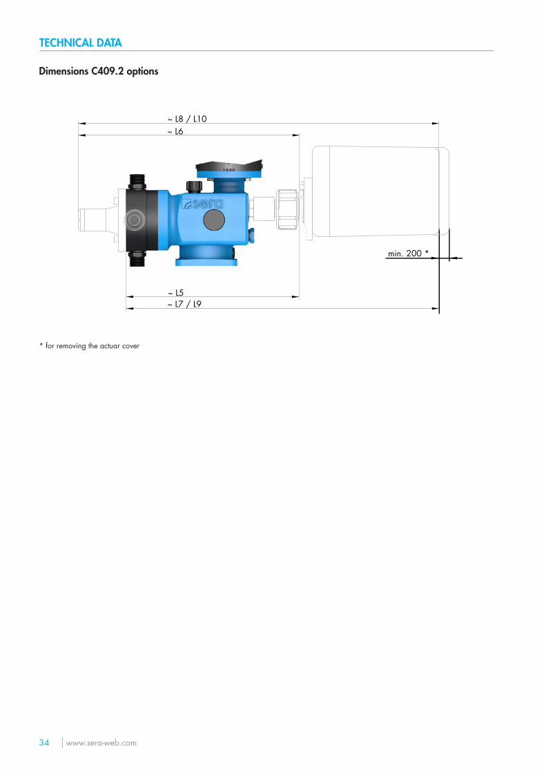
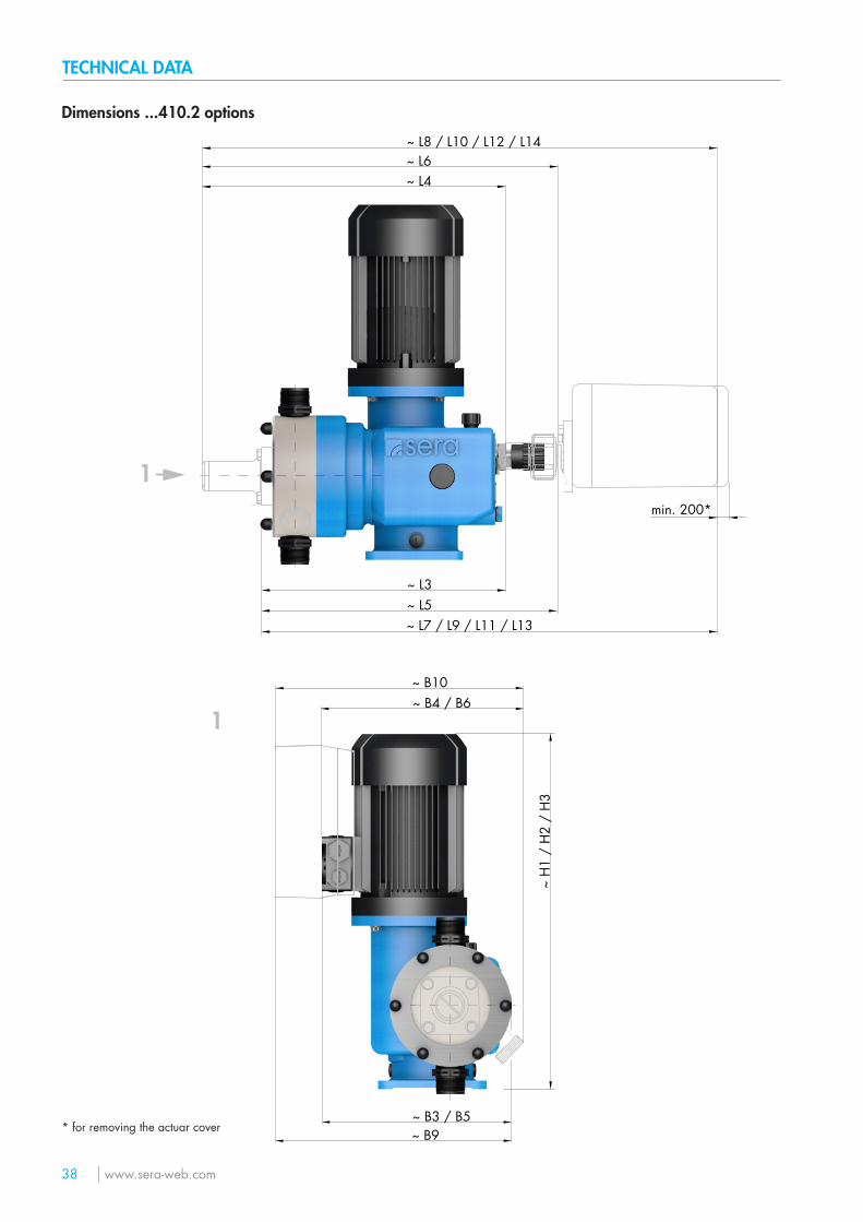
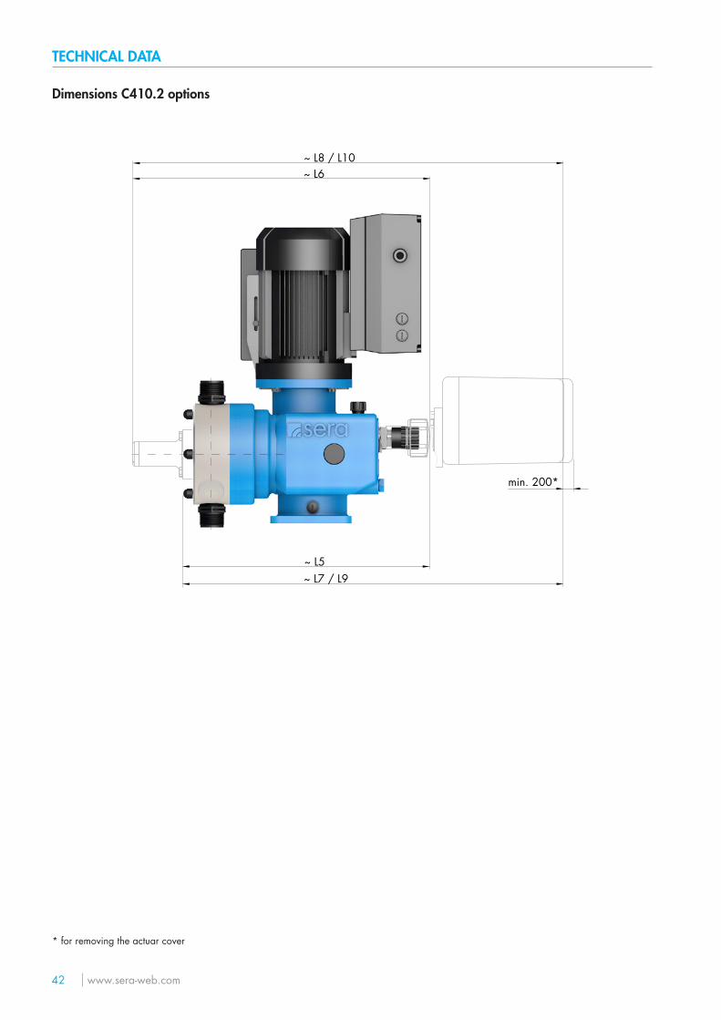
Dimensions ...409.2 options
~ B7~ B9
~ L3
~ L4
~ L5
~ L6~ L8 / L10 / L12 / L14
~ L7 / L9 / L11 / L13
1
~ H
3
1
~ B3 / B5
~ H
1 /
H2
~ B8~ B10
~ B4 / B6
min. 200*
* for removing the actuar cover
TECHNICAL DATA
www.sera-web.com 31
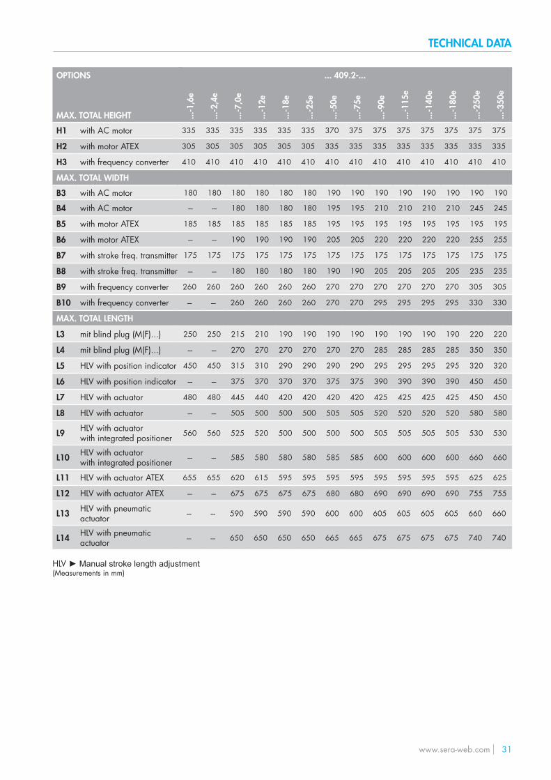
OPTIONS
MAX. TOTAL HEIGHT
H1 with AC motor
H2 with motor ATEX
H3 with frequency converter
MAX. TOTAL WIDTH
B3 with AC motor
B4 with AC motor
B5 with motor ATEX
B6 with motor ATEX
B7 with stroke freq. transmitter
B8 with stroke freq. transmitter
B9 with frequency converter
B10 with frequency converter
MAX. TOTAL LENGTH
L3 mit blind plug (M(F)...)
L4 mit blind plug (M(F)...)
L5 HLV with position indicator
L6 HLV with position indicator
L7 HLV with actuator
L8 HLV with actuator
L9 HLV with actuatorwith integrated positioner
L10 HLV with actuator with integrated positioner
L11 HLV with actuator ATEX
L12 HLV with actuator ATEX
L13 HLV with pneumatic actuator
L14 HLV with pneumatic actuator
HLV ► Manual stroke length adjustment(Measurements in mm)
... 409.2-...
...-1
,6e
...-2
,4e
...-7
,0e
...-1
2e
...-1
8e
...-2
5e
...-5
0e
...-7
5e
...-9
0e
...-1
15e
...-1
40e
...-1
80e
...-2
50e
...-3
50e
335 335 335 335 335 335 370 375 375 375 375 375 375 375
305 305 305 305 305 305 335 335 335 335 335 335 335 335
410 410 410 410 410 410 410 410 410 410 410 410 410 410
180 180 180 180 180 180 190 190 190 190 190 190 190 190
--- --- 180 180 180 180 195 195 210 210 210 210 245 245
185 185 185 185 185 185 195 195 195 195 195 195 195 195
--- --- 190 190 190 190 205 205 220 220 220 220 255 255
175 175 175 175 175 175 175 175 175 175 175 175 175 175
--- --- 180 180 180 180 190 190 205 205 205 205 235 235
260 260 260 260 260 260 270 270 270 270 270 270 305 305
--- --- 260 260 260 260 270 270 295 295 295 295 330 330
250 250 215 210 190 190 190 190 190 190 190 190 220 220
--- --- 270 270 270 270 270 270 285 285 285 285 350 350
450 450 315 310 290 290 290 290 295 295 295 295 320 320
--- --- 375 370 370 370 375 375 390 390 390 390 450 450
480 480 445 440 420 420 420 420 425 425 425 425 450 450
--- --- 505 500 500 500 505 505 520 520 520 520 580 580
560 560 525 520 500 500 500 500 505 505 505 505 530 530
--- --- 585 580 580 580 585 585 600 600 600 600 660 660
655 655 620 615 595 595 595 595 595 595 595 595 625 625
--- --- 675 675 675 675 680 680 690 690 690 690 755 755
--- --- 590 590 590 590 600 600 605 605 605 605 660 660
--- --- 650 650 650 650 665 665 675 675 675 675 740 740
TECHNICAL DATA
32 www.sera-web.com
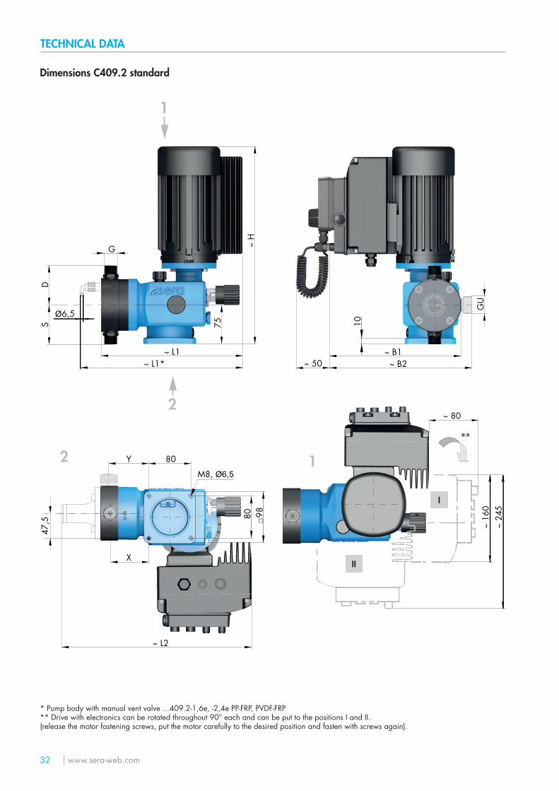
Dimensions C409.2 standard
I
II
~ H
75
~ B1~ B2~ L1*
~ L1~ 50
~ L2
~ 24
5~
160
~ 80
2
1
12
DS
G
GU
10
98
80
□
Y
47,5
X
80
**
M8, Ø6,5
6,5Ø
* Pump body with manual vent valve ...409.2-1,6e, -2,4e PP-FRP, PVDF-FRP** Drive with electronics can be rotated throughout 90° each and can be put to the positions I and II.(release the motor fastening screws, put the motor carefully to the desired position and fasten with screws again).
TECHNICAL DATA
www.sera-web.com 33
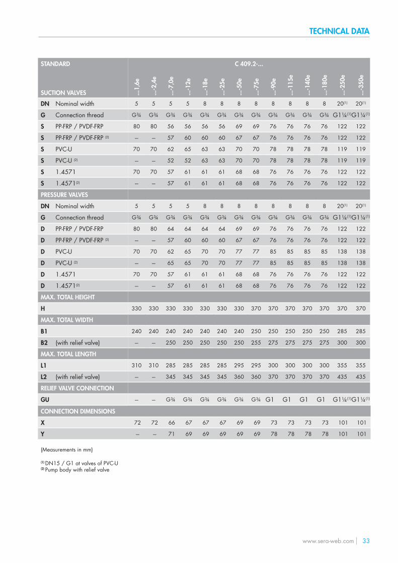
C 409.2-...
...1,
6e
...-2
,4e
...-7
,0e
...-1
2e
...-1
8e
...-2
5e
...-5
0e
...-7
5e
...-9
0e
...-1
15e
...-1
40e
...-1
80e
...-2
50e
...-3
50e
5 5 5 5 8 8 8 8 8 8 8 8 20(1) 20(1)
G¾ G¾ G¾ G¾ G¾ G¾ G¾ G¾ G¾ G¾ G¾ G¾ G1¼(1)G1¼(1)
80 80 56 56 56 56 69 69 76 76 76 76 122 122
--- --- 57 60 60 60 67 67 76 76 76 76 122 122
70 70 62 65 63 63 70 70 78 78 78 78 119 119
--- --- 52 52 63 63 70 70 78 78 78 78 119 119
70 70 57 61 61 61 68 68 76 76 76 76 122 122
--- --- 57 61 61 61 68 68 76 76 76 76 122 122
5 5 5 5 8 8 8 8 8 8 8 8 20(1) 20(1)
G¾ G¾ G¾ G¾ G¾ G¾ G¾ G¾ G¾ G¾ G¾ G¾ G1¼(1)G1¼(1)
80 80 64 64 64 64 69 69 76 76 76 76 122 122
--- --- 57 60 60 60 67 67 76 76 76 76 122 122
70 70 62 65 70 70 77 77 85 85 85 85 138 138
--- --- 65 65 70 70 77 77 85 85 85 85 138 138
70 70 57 61 61 61 68 68 76 76 76 76 122 122
--- --- 57 61 61 61 68 68 76 76 76 76 122 122
330 330 330 330 330 330 330 370 370 370 370 370 370 370
240 240 240 240 240 240 240 250 250 250 250 250 285 285
--- --- 250 250 250 250 250 255 275 275 275 275 300 300
310 310 285 285 285 285 295 295 300 300 300 300 355 355
--- --- 345 345 345 345 360 360 370 370 370 370 435 435
--- --- G¾ G¾ G¾ G¾ G¾ G¾ G1 G1 G1 G1 G1¼(1)G1¼(1)
CONNECTION DIMENSIONS
X
Y
72 72 66 67 67 67 69 69 73 73 73 73 101 101
--- --- 71 69 69 69 69 69 78 78 78 78 101 101
STANDARD
SUCTION VALVES
DN Nominal width
G Connection thread
S PP-FRP / PVDF-FRP
S PP-FRP / PVDF-FRP (2)
S PVC-U
S PVC-U (2)
S 1.4571
S 1.4571(2)
PRESSURE VALVES
DN Nominal width
G Connection thread
D PP-FRP / PVDF-FRP
D PP-FRP / PVDF-FRP (2)
D PVC-U
D PVC-U (2)
D 1.4571
D 1.4571(2)
MAX. TOTAL HEIGHT
H
MAX. TOTAL WIDTH
B1
B2 (with relief valve)
MAX. TOTAL LENGTH
L1
L2 (with relief valve)
RELIEF VALVE CONNECTION
GU
(Measurements in mm)
(1) DN15 / G1 at valves of PVC-U(2) Pump body with relief valve
TECHNICAL DATA
34 www.sera-web.com
Dimensions C409.2 options
min. 200 *
~ L5
~ L6~ L8 / L10
~ L7 / L9
* for removing the actuar cover
TECHNICAL DATA
www.sera-web.com 35
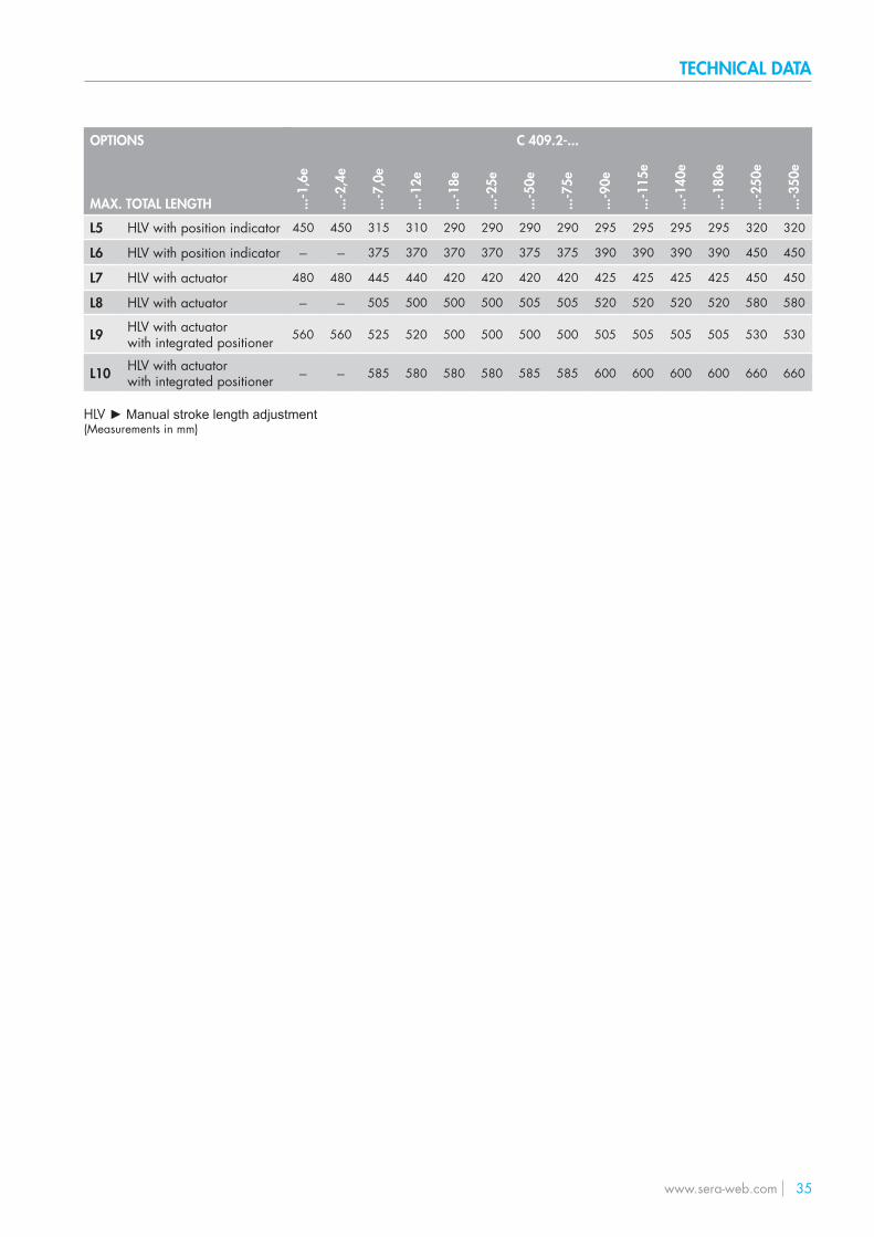
OPTIONS
MAX. TOTAL LENGTH
L5 HLV with position indicator
L6 HLV with position indicator
L7 HLV with actuator
L8 HLV with actuator
L9 HLV with actuatorwith integrated positioner
L10 HLV with actuator with integrated positioner
HLV ► Manual stroke length adjustment(Measurements in mm)
C 409.2-...
...-1
,6e
...-2
,4e
...-7
,0e
...-1
2e
...-1
8e
...-2
5e
...-5
0e
...-7
5e
...-9
0e
...-1
15e
...-1
40e
...-1
80e
...-2
50e
...-3
50e
450 450 315 310 290 290 290 290 295 295 295 295 320 320
--- --- 375 370 370 370 375 375 390 390 390 390 450 450
480 480 445 440 420 420 420 420 425 425 425 425 450 450
--- --- 505 500 500 500 505 505 520 520 520 520 580 580
560 560 525 520 500 500 500 500 505 505 505 505 530 530
--- --- 585 580 580 580 585 585 600 600 600 600 660 660
TECHNICAL DATA
36 www.sera-web.com
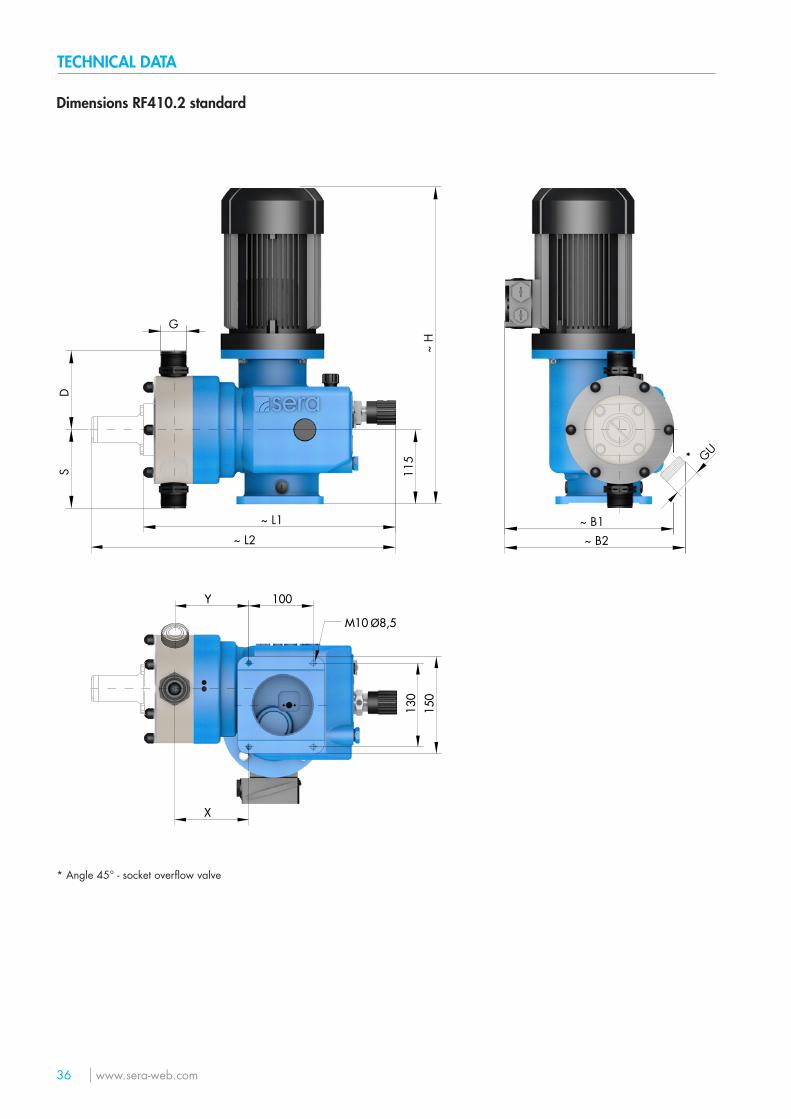
Dimensions RF410.2 standard
115
~ H
~ L2
~ L1 ~ B1~ B2
SD
G
GU
M10 Ø8,5
130
150
100Y
X
*
* Angle 45° - socket overflow valve
TECHNICAL DATA
www.sera-web.com 37
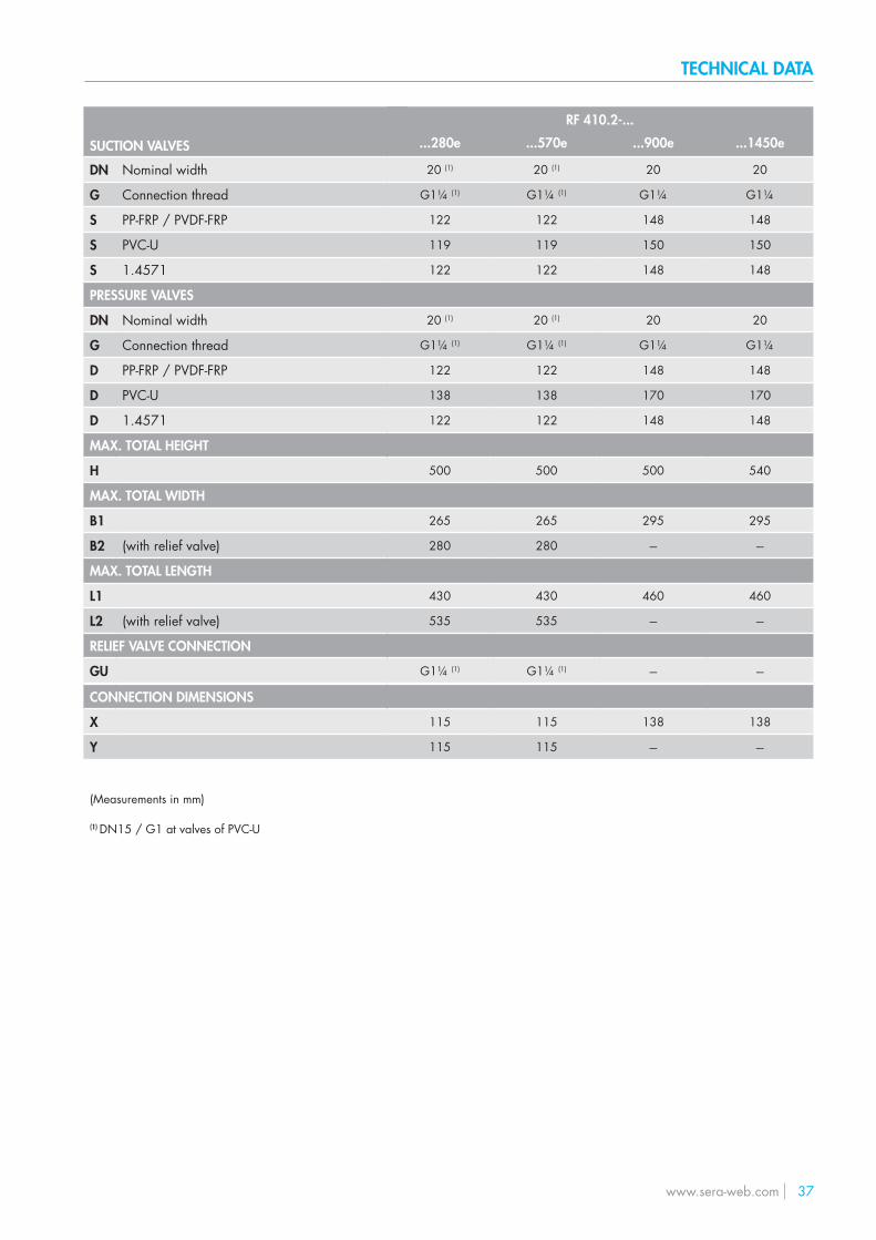
SUCTION VALVES
DN Nominal width
G Connection thread
S PP-FRP / PVDF-FRP
S PVC-U
S 1.4571
PRESSURE VALVES
DN Nominal width
G Connection thread
D PP-FRP / PVDF-FRP
D PVC-U
D 1.4571
MAX. TOTAL HEIGHT
H
MAX. TOTAL WIDTH
B1
B2 (with relief valve)
MAX. TOTAL LENGTH
L1
L2 (with relief valve)
RELIEF VALVE CONNECTION
GU
RF 410.2-...
...280e ...570e ...900e ...1450e
20 (1) 20 (1) 20 20
G1¼ (1) G1¼ (1) G1¼ G1¼
122 122 148 148
119 119 150 150
122 122 148 148
20 (1) 20 (1) 20 20
G1¼ (1) G1¼ (1) G1¼ G1¼
122 122 148 148
138 138 170 170
122 122 148 148
500 500 500 540
265 265 295 295
280 280 --- ---
430 430 460 460
535 535 --- ---
G1¼ (1) G1¼ (1) --- ---
CONNECTION DIMENSIONS
X
Y
115 115 138 138
115 115 --- ---
(Measurements in mm)
(1) DN15 / G1 at valves of PVC-U
TECHNICAL DATA
38 www.sera-web.com
Dimensions ...410.2 options
~ B3 / B5~ B9
~ L3
~ L4
~ L5
~ L6~ L8 / L10 / L12 / L14
~ L7 / L9 / L11 / L13
1
~ H
1 /
H2
/ H
3
~ B4 / B6~ B10
min. 200*
1
* for removing the actuar cover
TECHNICAL DATA
www.sera-web.com 39
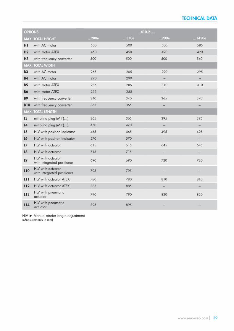
...410.2-....
...280e ...570e ...900e ...1450e
500 500 500 585
450 450 490 490
500 500 500 540
265 265 290 295
290 290 --- ---
285 285 310 310
255 255 --- ---
340 340 365 370
365 365 --- ---
365 365 395 395
470 470 --- ---
465 465 495 495
570 570 --- ---
615 615 645 645
715 715 --- ---
690 690 720 720
795 795 --- ---
780 780 810 810
885 885 --- ---
790 790 820 820
895 895 --- ---
OPTIONS
MAX. TOTAL HEIGHT
H1 with AC motor
H2 with motor ATEX
H3 with frequency converter
MAX. TOTAL WIDTH
B3 with AC motor
B4 with AC motor
B5 with motor ATEX
B6 with motor ATEX
B9 with frequency converter
B10 with frequency converter
MAX. TOTAL LENGTH
L3 mit blind plug (M(F)...)
L4 mit blind plug (M(F)...)
L5 HLV with position indicator
L6 HLV with position indicator
L7 HLV with actuator
L8 HLV with actuator
L9 HLV with actuatorwith integrated positioner
L10 HLV with actuator with integrated positioner
L11 HLV with actuator ATEX
L12 HLV with actuator ATEX
L13 HLV with pneumatic actuator
L14 HLV with pneumatic actuator
HLV ► Manual stroke length adjustment(Measurements in mm)
TECHNICAL DATA
40 www.sera-web.com
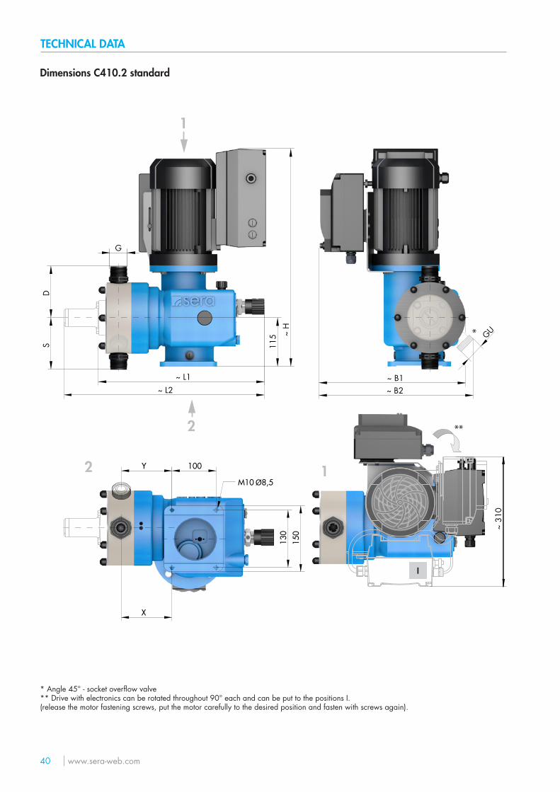
Dimensions C410.2 standard
115 ~
H
~ L2~ L1 ~ B1
~ B2
SD
G
GUM10 Ø8,5
130
150
100Y
X
**2
1
12
~ 31
0
*
* Angle 45° - socket overflow valve** Drive with electronics can be rotated throughout 90° each and can be put to the positions I.(release the motor fastening screws, put the motor carefully to the desired position and fasten with screws again).
I
TECHNICAL DATA
www.sera-web.com 41
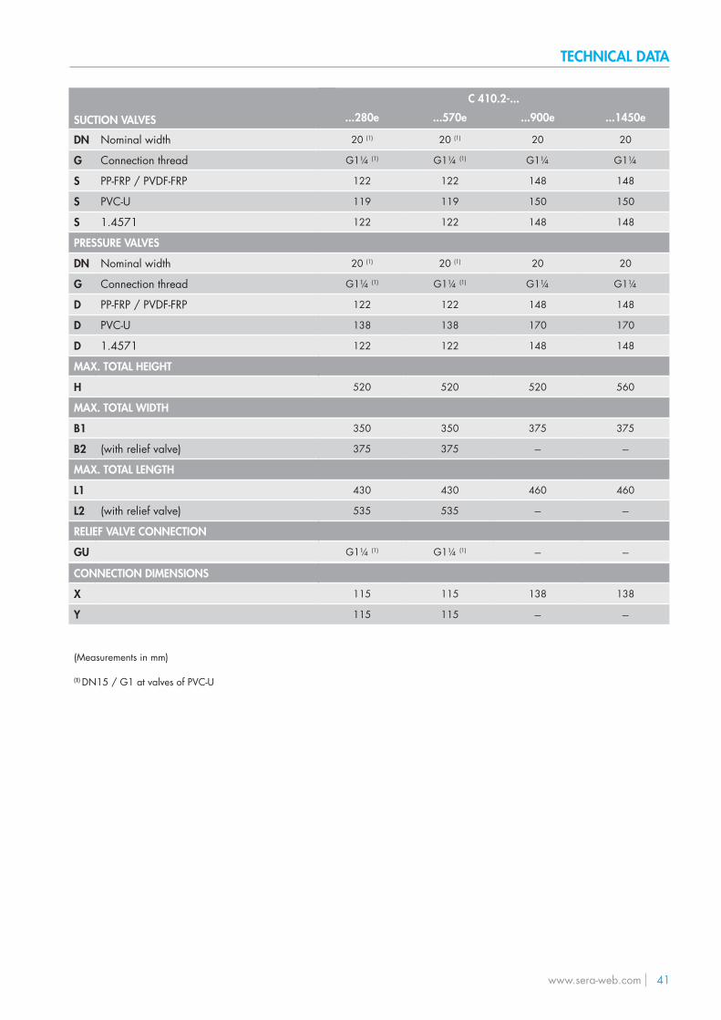
SUCTION VALVES
DN Nominal width
G Connection thread
S PP-FRP / PVDF-FRP
S PVC-U
S 1.4571
PRESSURE VALVES
DN Nominal width
G Connection thread
D PP-FRP / PVDF-FRP
D PVC-U
D 1.4571
MAX. TOTAL HEIGHT
H
MAX. TOTAL WIDTH
B1
B2 (with relief valve)
MAX. TOTAL LENGTH
L1
L2 (with relief valve)
RELIEF VALVE CONNECTION
GU
C 410.2-...
...280e ...570e ...900e ...1450e
20 (1) 20 (1) 20 20
G1¼ (1) G1¼ (1) G1¼ G1¼
122 122 148 148
119 119 150 150
122 122 148 148
20 (1) 20 (1) 20 20
G1¼ (1) G1¼ (1) G1¼ G1¼
122 122 148 148
138 138 170 170
122 122 148 148
520 520 520 560
350 350 375 375
375 375 --- ---
430 430 460 460
535 535 --- ---
G1¼ (1) G1¼ (1) --- ---
CONNECTION DIMENSIONS
X
Y
115 115 138 138
115 115 --- ---
(Measurements in mm)
(1) DN15 / G1 at valves of PVC-U
TECHNICAL DATA
42 www.sera-web.com
Dimensions C410.2 options
~ L5
~ L6~ L8 / L10
~ L7 / L9
min. 200*
* for removing the actuar cover
TECHNICAL DATA
www.sera-web.com 43
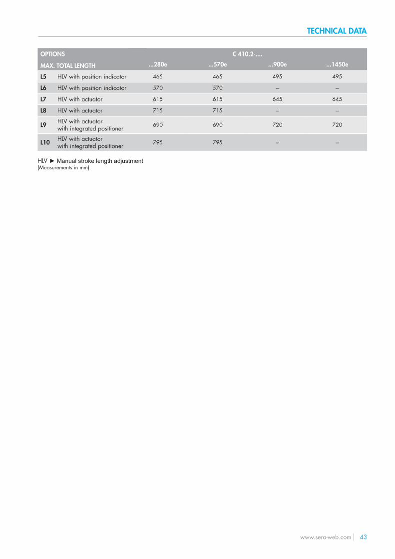
C 410.2-....
...280e ...570e ...900e ...1450e
465 465 495 495
570 570 --- ---
615 615 645 645
715 715 --- ---
690 690 720 720
795 795 --- ---
OPTIONS
MAX. TOTAL LENGTH
L5 HLV with position indicator
L6 HLV with position indicator
L7 HLV with actuator
L8 HLV with actuator
L9 HLV with actuatorwith integrated positioner
L10 HLV with actuator with integrated positioner
HLV ► Manual stroke length adjustment(Measurements in mm)
44 www.sera-web.com
ASSEMBLY / INSTALLATION
NOTE
Pump design data for dosing and its temperature can be found in the order confirmation.
NOTE
Operating conditions:Ambient temperature, relative air humidity and max. installation altitude ► see chapter „Technical data“.
■ The standard model of the pump is only approved for installation in dry areas in a non-aggressive atmosphere. ■ Protect the pump from heat sources, direct sunlight and UV light. ■ See “Dimensions” chapter for dimensions of the pump connections and fixing holes. ■ Fixing the pump with at least four bolts above the pump base is required for safe operation. ■ Install the pump so that there is no vibration and no tension and that it is aligned precisely. ■ Install the pump at the optimum possible operating height. Mount the pump so that the valves are vertical. ■ Ensure that there is sufficient space around the pump body and the suction and pressure valve so that these parts can be
easily dismantled if required. ■ Design the nominal diameters of the downstream piping and the valves installed in the system to be the same size or larger
than the nominal inlet and outlet diameters of the pump. ■ To check the pressure ratios in the piping system, it is recommended to provide connections for pressure measurement
fittings (e.g. manometers) near the suction and pressure ports. ■ Drain valves must be provided. ■ Before connecting the pipes, remove the plastic caps on the suction and pressure ports of the pump. ■ Check the fastening bolts for the pump body for tightness and tighten if necessary, see chapter “Overview of the tightening
torques”. ■ Connect pipes to the pump so that there are no forces acting on the pump, such as e.g. misalignment, weight or strain of
the pipe. ■ Keep the suction pipes as short as possible. ■ Use pressure and medium resistant hoses / pipes. ■ All pipes and containers connected to the pump must comply with the regulations and must be cleaned, tension-free and
intact. ■ Display devices must be easily accessible and readable.
In order to avoid cavitation, overload or excessive delivery, the following points should be noted:
■ Avoid high suction heights. ■ Keep pipes as short as possible. ■ Select sufficiently large nominal diameters. ■ Avoid unnecessary choke points. ■ Install a pulsation damper. ■ Install overpressure protection. ■ Install a pressure-sustaining valve, if necessary ■ Provide feed line for outgassing media.
WARNING
The pump with a control is only designed for operation outside Ex-zonest!
WARNING
Observe and follow the safety instructions by all means.See the additional instructions „SAFETY INSTRUCTIONS“.Man, machine and environment are endangered if the safety instructions are not observed.
SI01
www.sera-web.com 45
ASSEMBLY / INSTALLATION
1
1.2
1.4
2
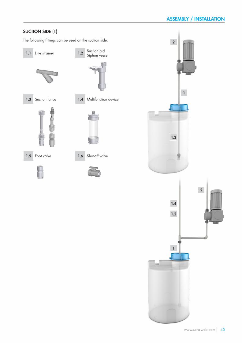
SUCTION SIDE (1)
The following fittings can be used on the suction side:
1.1 Line strainer 1.2 Suction aidSiphon vessel
1.3 Suction lance 1.4 Multifunction device
1.5 Foot valve 1.6 Shut-off valve
1.3
2
1
46 www.sera-web.com
ASSEMBLY / INSTALLATION
1
2.6
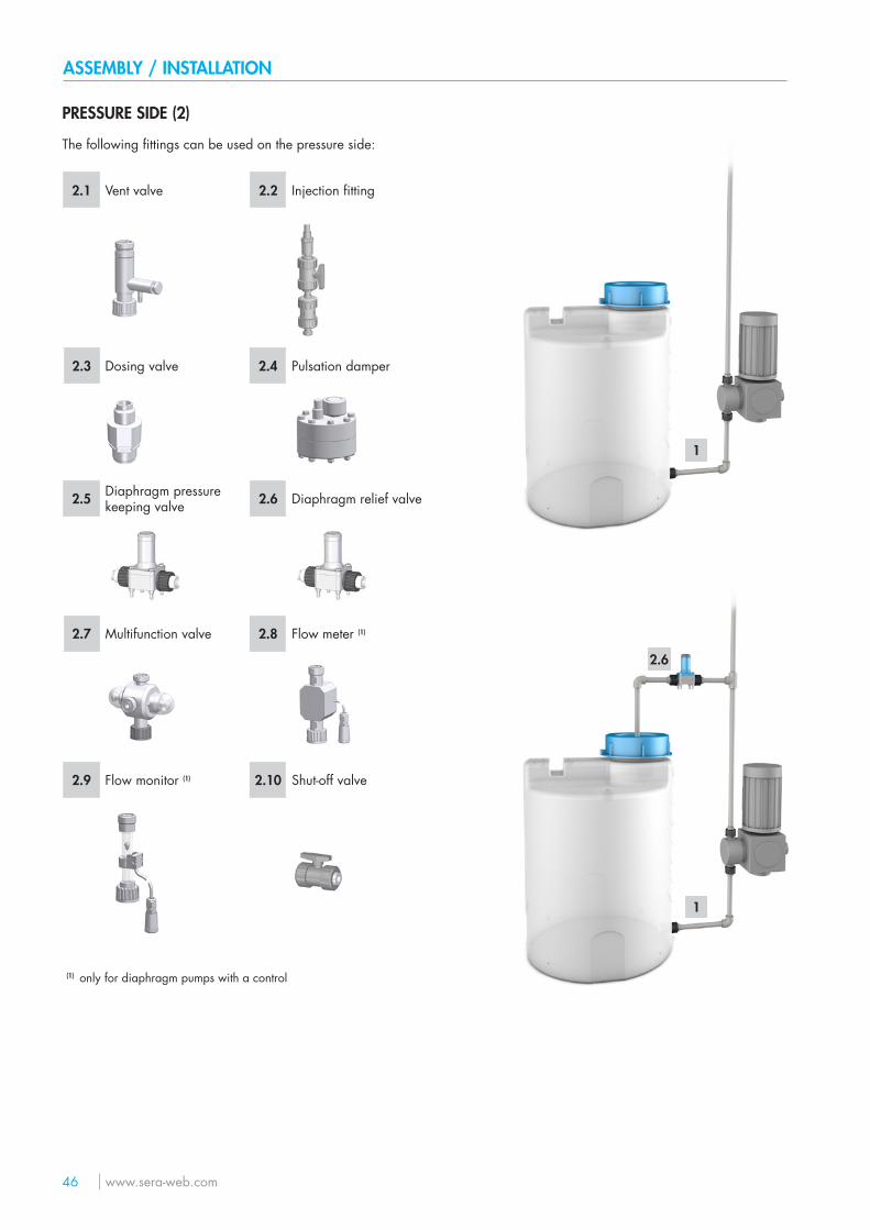
PRESSURE SIDE (2)
The following fittings can be used on the pressure side:
2.1 Vent valve 2.2 Injection fitting
2.3 Dosing valve 2.4 Pulsation damper
2.5 Diaphragm pressure keeping valve 2.6 Diaphragm relief valve
2.7 Multifunction valve 2.8 Flow meter (1)
2.9 Flow monitor (1) 2.10 Shut-off valve
(1) only for diaphragm pumps with a control
1
www.sera-web.com 47
ASSEMBLY / INSTALLATION
SUCTION SIDE (1)
Line strainer (1.1)
Connect suction line slightly above the bottom of the tank and install a line strainer (0.1 – 0.5 mm mesh size – dependingon valve nominal diameter of the pump).
ATTENTION
If impurities are not removed, this results in malfunctions of the pump and the system.
Suction aid / siphon vessel (1.2)
For high tanks without connection on the bottom of the tank ► install suction aid / siphon vessel.Thereby, pay attention to accelerating pressures which may be generated in a long suction pipe.
Suction lance (1.3)
Install a suction lance for removal of chemicals from tanks and barrels.The integrated foot valve prevents the backflow of the suctioned medium.The suction lances are equipped with a level switch for „empty“ signal.
Multifunction device (1.4)
The multifunction device is installed in the suction side piping of the pump and is used for determination of the deliveryrate of pumps under real operating conditions.The device can be filled either using a pending tank volume (communicating container) or using a hand vacuum pump.
Foot valve (1.5)
To prevent running dry of the suction line ► install foot valve (check valve) at the end of the suction line.
48 www.sera-web.com
ASSEMBLY / INSTALLATION
PRESSURE SIDE (2)
Vent valve (2.1)
If air can be drawn in due to falling liquid level in the suction tank and at the same time delivered to a pressurised line or against a pressure-sustaining valve ► install vent valve in the pressure line.
NOTE
The delivery flow can be interrupted if there is air in the suction line!
Injection fitting (2.2)
Install an injection fitting that routes into a main line to prevent the backflow of the pumped medium in the dosing line.
WARNING
Unwanted mixing in the dosing line occurs if any possible backflow from the main line is not prevented.
Dosing valve (2.3)
Installation of the dosing valve prevents the liquid from the system to be treated being able to penetrate into the dosing line.
Pulsation damper (2.4)
Damping of the pulsation by installation of pulsation dampers if:
■ a low-pulsation delivery flow is desired for process reasons, ■ acceleration forces caused by the piping geometry must be removed.
Install pulsation damper as close as possible to the pump head.If both pulsation damper and pressure-sustaining valve should be integrated, install the pressure-sustaining valvebetween pump and pulsation damper.
WARNING
Undamped acceleration forces can result in the following faults / damage:
■ flow rate fluctuations ■ dosing errors ■ pressure surges ■ valve shocks ■ increased wear on the suction and pressure sides of the pump ■ mechanical destruction of the pump ■ leaks and valve shocks if the permissible maximum pressure on the pump pressure ■ side is exceeded ■ damage to the piping and its installed fittings
www.sera-web.com 49
ASSEMBLY / INSTALLATION
Diaphragm pressure-keeping valve (2.5)
If dosing into a main line with negative pressure ► install pressure-keeping valve in the dosing line.
ATTENTION
It must be ensured during the installation that excess delivery (due to positive pressure difference (≥ > 1 bar) between pres-sure and suction sides) is avoided.
Diaphragm relief valve (2.6)
If the permissible pressure in the system can be exceeded by closing any shut-off valve or by clogging of the line ► install dia-phragm relief valve.
When using an external overflow valve, the following is applicable for the return line:
■ Route the return line sloping downward into the storage tank which is under atmospheric pressure or into an open drainage channel.
■ Or connect directly to the pump suction line, but only if there is no check valve in the suction line (e.g. foot valve of a sucti-on lance).
ATTENTION
Shut-off valves must not be closed when the pump is running!
WARNING
An overpressure protection device (e.g. relief valve) must generally be provided if the permissible operating pressure can be exceeded.
ATTENTION
If the permissible operating pressure is exceeded and the pump is not equipped with overpressure protection, the pump will be damaged.
WARNING
The pumped medium can spray out if the pump is damaged.
Multifunction valve (2.7)
The multifunction valve provides the following functions:
■ pressure-keeping valve function, ■ overflow valve function, ■ pressure relief function, ■ venting.
The multifunction valve is mounted directly on the pump pressure port.
50 www.sera-web.com
ASSEMBLY / INSTALLATION
Flow meter (2.8)
For measurement and monitoring of the flow rate ► install flow meter.The application range is restricted to media that are similar to water.The flow meter is screwed upright on the pressure port of the pump and connected to the pump electronics via the input for flow monitoring.
Flow monitor (2.9)
To record the flow rate of the pump ► install flow monitor.The application range is restricted to media that are similar to water.The flow monitor is screwed upright on the suction port of the pump and connected to the pump electronics via the input for flow monitoring.
www.sera-web.com 51
EXPLOSION-HAZARDOUS AREAS / OPERATION
WARNING
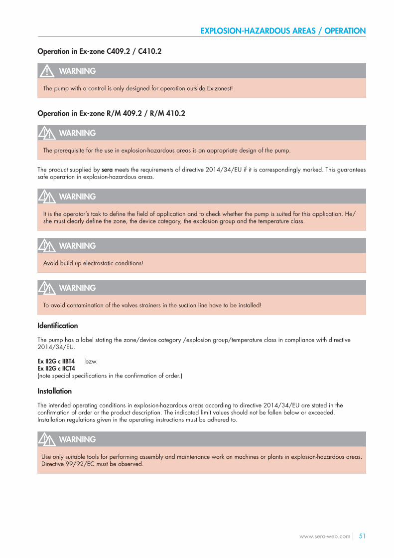
The pump with a control is only designed for operation outside Ex-zonest!
WARNING
The prerequisite for the use in explosion-hazardous areas is an appropriate design of the pump.
The product supplied by sera meets the requirements of directive 2014/34/EU if it is correspondingly marked. This guaranteessafe operation in explosion-hazardous areas.
WARNING
It is the operator’s task to define the field of application and to check whether the pump is suited for this application. He/she must clearly define the zone, the device category, the explosion group and the temperature class.
WARNING
Avoid build up electrostatic conditions!
WARNING
To avoid contamination of the valves strainers in the suction line have to be installed!
Identification
The pump has a label stating the zone/device category /explosion group/temperature class in compliance with directive2014/34/EU.
Ex II2G c IIBT4 bzw.Ex II2G c IICT4(note special specifications in the confirmation of order.)
Installation
The intended operating conditions in explosion-hazardous areas according to directive 2014/34/EU are stated in theconfirmation of order or the product description. The indicated limit values should not be fallen below or exceeded.Installation regulations given in the operating instructions must be adhered to.
WARNING
Use only suitable tools for performing assembly and maintenance work on machines or plants in explosion-hazardous areas.Directive 99/92/EC must be observed.
Operation in Ex-zone C409.2 / C410.2
Operation in Ex-zone R/M 409.2 / R/M 410.2
52 www.sera-web.com
OPERATION / EXPLOSION-HAZARDOUS AREAS
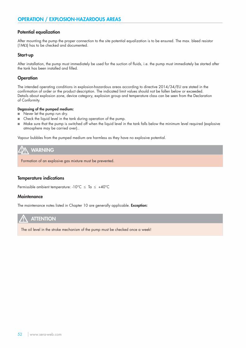
Potential equalization
After mounting the pump the proper connection to the site potential equalization is to be ensured. The max. bleed resistor (1MΩ) has to be checked and documented.
Start-up
After installation, the pump must immediately be used for the suction of fluids, i.e. the pump must immediately be started after the tank has been installed and filled.
Operation
The intended operating conditions in explosion-hazardous areas according to directive 2014/34/EU are stated in theconfirmation of order or the product description. The indicated limit values should not be fallen below or exceeded.Details about explosion zone, device category, explosion group and temperature class can be seen from the Declarationof Conformity.
Degassing of the pumped medium: ■ Never let the pump run dry. ■ Check the liquid level in the tank during operation of the pump. ■ Make sure that the pump is switched off when the liquid level in the tank falls below the minimum level required (explosive
atmosphere may be carried over)..
Vapour bubbles from the pumped medium are harmless as they have no explosive potential.
WARNING
Formation of an explosive gas mixture must be prevented.
Temperature indications
Permissible ambient temperature: -10°C ≤ Ta ≤ +40°C
Maintenance
The maintenance notes listed in Chapter 10 are generally applicable. Exception:
ATTENTION
The oil level in the stroke mechanism of the pump must be checked once a week!
www.sera-web.com 53
Adequate fastening at the pump foot and compliance with the operating parameters specified in the technical data arerequired for the operation of the pump.
Checks before every start-up:
■ Check all connections for tightness. ■ Tighten fixing bolts of the pump body with the specified tightening torques
(see „Overview of the tightening torques“ chapter). ■ Check of the electrical connections. ■ Check of the mains voltage on the rating plate with the local conditions.
START-UP
Driving motor
Preconditions:
■ Make sure that voltage and frequency correspond with the indications on the type plate of the motor. Permissible voltage tolerance (DIN VDE 0530).
■ For rated voltage ► + 10 % ■ For rated voltage range ► ± 5 % ■ The connecting cable must be dimensioned according to the motor characteristics. ■ Secure connecting cable with a strain relief. ■ The nominal motor power refers to an ambient temperature and an installation site ► see chapter „TECHNICAL DATA“ .
Motor output will be reduced if these values are exceeded (see VDE 0530). ■ Adapted for “moderate” groupe of climates according to IEC 721-2-1.
WARNING
Observe and follow the safety instructions by all means.See the additional instructions „SAFETY INSTRUCTIONS“.Man, machine and environment are endangered if the safety instructions are not observed.
SI01
54 www.sera-web.com
ELECTRICAL CONNECTIONS
NOTE
Operating voltage range see chapter „TECHNICAL DATA“.
NOTE
Pump without control:Motor connection see chapter „Drive motor“ in the PRODUCT DESCRIPTION.
NOTE
Pump with a control:Electrical iterfaces see the additional operation instructions for the CONTROL.
ATTENTION
Pump with a control:The pump restarts in the selected operating mode with the specified parameters after switching on again or after restoration of the power supply following a power failure.
www.sera-web.com 55
MAINTENANCE
Check the following at regular intervals:
■ Tight fit of piping. ■ Tight fit of pressure and suction valve. ■ Proper condition of the electrical connections. ■ Tight fit of the screws for fastening the pump body (check this at least every three months). ■ For the tightening torques of the mounting screws, please see Chapter „Overview of the tightening torques“. ■ Additionally with motor pumps: Check oil level regularly (oil eye).
WARNING
Observe and follow the safety instructions by all means.See the additional instructions „SAFETY INSTRUCTIONS“.Man, machine and environment are endangered if the safety instructions are not observed.
SI01
Drive motor
The electric motor should always be kept clean so that neither dust, dirt, oil nor other contaminates may affect thecorrect operation.
In addition, we recommend to ensure that:
■ The motor does not produce strong vibrations ■ Suction and blowing openings for the supply of cooling air are not closed or restricted (may lead to unnecessary high
temperatures in the windings)
The ball bearings inserted in the motor are lubricated for life.
56 www.sera-web.com
MAINTENANCE
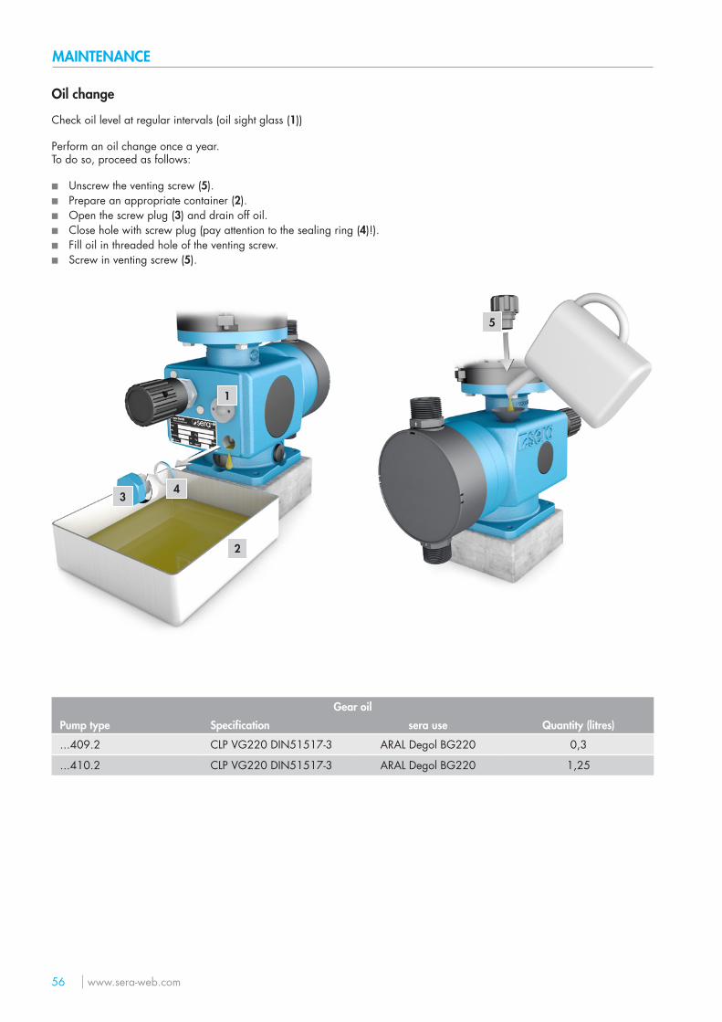
Oil change
Check oil level at regular intervals (oil sight glass (1))
Perform an oil change once a year.To do so, proceed as follows:
■ Unscrew the venting screw (5). ■ Prepare an appropriate container (2). ■ Open the screw plug (3) and drain off oil. ■ Close hole with screw plug (pay attention to the sealing ring (4)!). ■ Fill oil in threaded hole of the venting screw. ■ Screw in venting screw (5).
2
1
34
5
Gear oil
Pump type Specification sera use Quantity (litres)
...409.2 CLP VG220 DIN51517-3 ARAL Degol BG220 0,3
...410.2 CLP VG220 DIN51517-3 ARAL Degol BG220 1,25
www.sera-web.com 57
MAINTENANCE
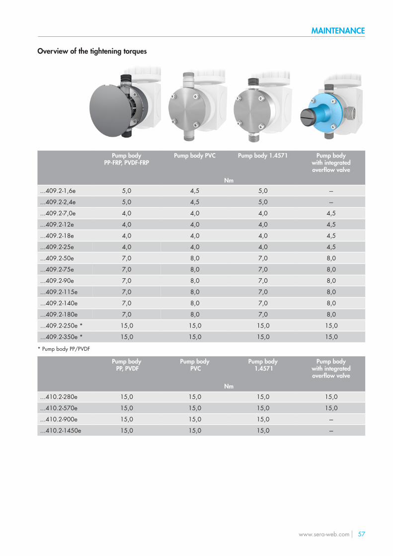
Overview of the tightening torques
Pump body PP-FRP, PVDF-FRP
Pump body PVC Pump body 1.4571 Pump body with integrated overflow valve
Nm
...409.2-1,6e 5,0 4,5 5,0 ---
...409.2-2,4e 5,0 4,5 5,0 ---
...409.2-7,0e 4,0 4,0 4,0 4,5
...409.2-12e 4,0 4,0 4,0 4,5
...409.2-18e 4,0 4,0 4,0 4,5
...409.2-25e 4,0 4,0 4,0 4,5
...409.2-50e 7,0 8,0 7,0 8,0
...409.2-75e 7,0 8,0 7,0 8,0
...409.2-90e 7,0 8,0 7,0 8,0
...409.2-115e 7,0 8,0 7,0 8,0
...409.2-140e 7,0 8,0 7,0 8,0
...409.2-180e 7,0 8,0 7,0 8,0
...409.2-250e * 15,0 15,0 15,0 15,0
...409.2-350e * 15,0 15,0 15,0 15,0
* Pump body PP/PVDF
...410.2-280e 15,0 15,0 15,0 15,0
...410.2-570e 15,0 15,0 15,0 15,0
...410.2-900e 15,0 15,0 15,0 ---
...410.2-1450e 15,0 15,0 15,0 ---
Pump body PP, PVDF
Pump body PVC
Pump body 1.4571
Pump body with integrated overflow valve
Nm
58 www.sera-web.com
MAINTENANCE
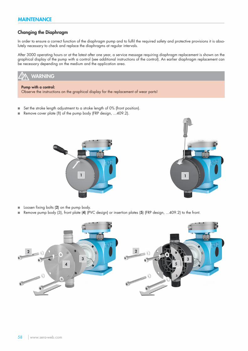
■ Set the stroke length adjustment to a stroke length of 0% (front position). ■ Remove cover plate (1) of the pump body (FRP design, ...409.2).
1 1
■ Loosen fixing bolts (2) on the pump body. ■ Remove pump body (3), front plate (4) (PVC design) or insertion plates (5) (FRP design, ...409.2) to the front.
2
34
2
35
Changing the Diaphragm
In order to ensure a correct function of the diaphragm pump and to fulfil the required safety and protective provisions it is abso-lutely necessary to check and replace the diaphragms at regular intervals.
After 3000 operating hours or at the latest after one year, a service message requiring diaphragm replacement is shown on the graphical display of the pump with a control (see additional instructions of the control). An earlier diaphragm replacement can be necessary depending on the medium and the application area.
WARNING
Pump with a control:Observe the instructions on the graphical display for the replacement of wear parts!
www.sera-web.com 59
MAINTENANCE
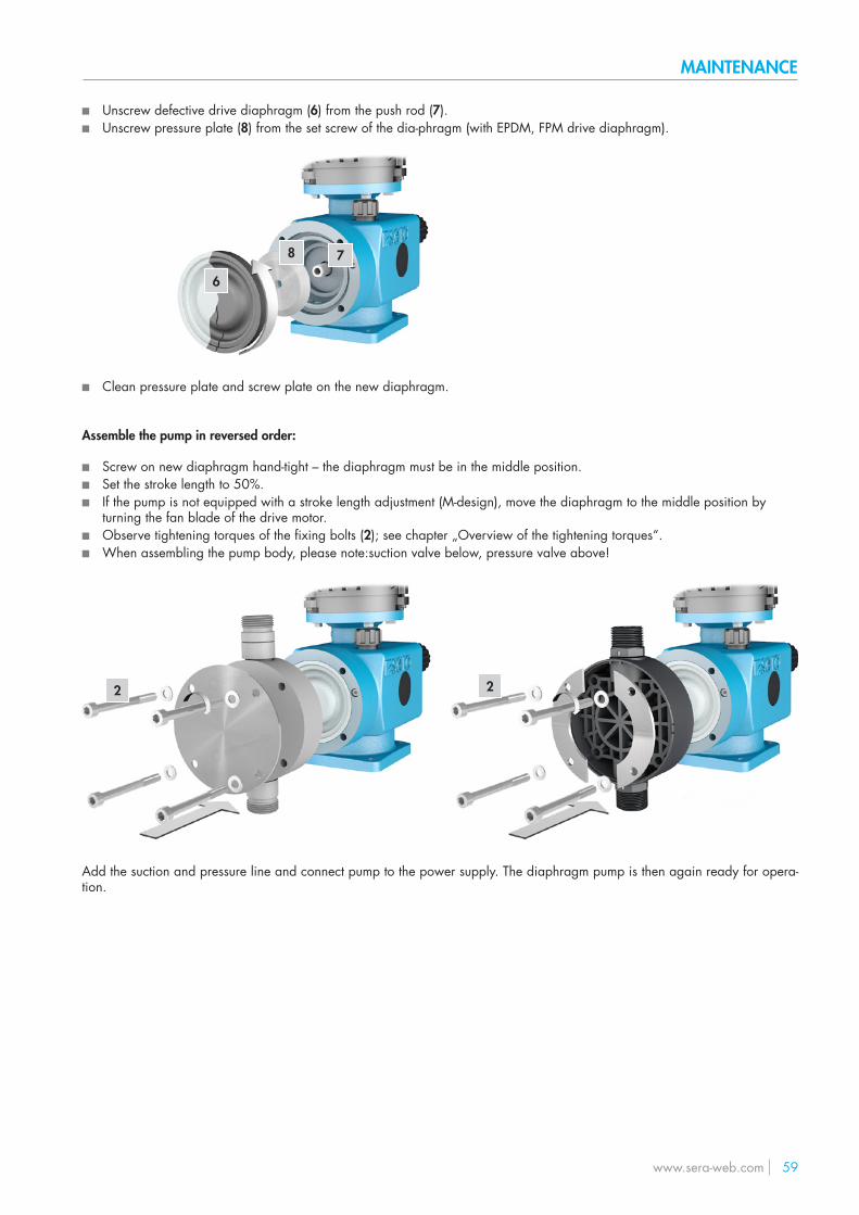
■ Unscrew defective drive diaphragm (6) from the push rod (7). ■ Unscrew pressure plate (8) from the set screw of the dia-phragm (with EPDM, FPM drive diaphragm).
6
78
■ Clean pressure plate and screw plate on the new diaphragm.
Assemble the pump in reversed order:
■ Screw on new diaphragm hand-tight – the diaphragm must be in the middle position. ■ Set the stroke length to 50%. ■ If the pump is not equipped with a stroke length adjustment (M-design), move the diaphragm to the middle position by
turning the fan blade of the drive motor. ■ Observe tightening torques of the fixing bolts (2); see chapter „Overview of the tightening torques“. ■ When assembling the pump body, please note:suction valve below, pressure valve above!
2 2
Add the suction and pressure line and connect pump to the power supply. The diaphragm pump is then again ready for opera-tion.
60 www.sera-web.com
MAINTENANCE
Overflow valve
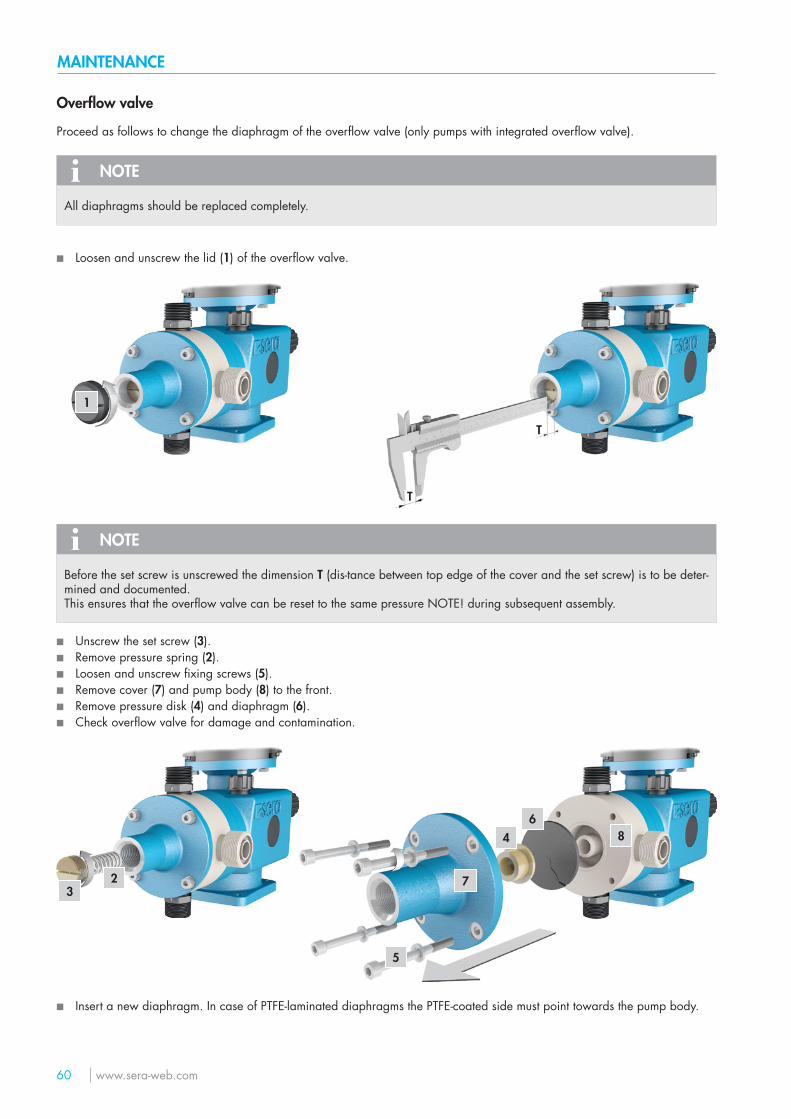
Proceed as follows to change the diaphragm of the overflow valve (only pumps with integrated overflow valve).
NOTE
All diaphragms should be replaced completely.
■ Loosen and unscrew the lid (1) of the overflow valve.
1
T
T
NOTE
Before the set screw is unscrewed the dimension T (dis-tance between top edge of the cover and the set screw) is to be deter-mined and documented.This ensures that the overflow valve can be reset to the same pressure NOTE! during subsequent assembly.
■ Unscrew the set screw (3). ■ Remove pressure spring (2). ■ Loosen and unscrew fixing screws (5). ■ Remove cover (7) and pump body (8) to the front. ■ Remove pressure disk (4) and diaphragm (6). ■ Check overflow valve for damage and contamination.
23
4 8
5
7
6
■ Insert a new diaphragm. In case of PTFE-laminated diaphragms the PTFE-coated side must point towards the pump body.
www.sera-web.com 61
MAINTENANCE
Assemble the pump in reversed order.
NOTE
The individual components should be cleaned thoroughly before assembly!!
NOTE
When the set nut is screwed in the dimension “T” which was determined beforehand is of great importance.
The initial opening pressure of the overflow valve is only reached when the NOTE! set screw is screwed in exactly according to dimension “T”!
ATTENTION
The screw-in depth of the set screw must not exceed the initial value. If the set pressure is increased, sera has to be consulted beforehand!
ATTENTION
Never screw in the set screw to a depth so that the pressure spring is compressed to solid length!
62 www.sera-web.com
MAINTENANCE
Spare and wearing parts
The following parts are considered as wearing parts of the pump:
■ Drive diaphragm (diaphragm kit) ■ Diaphragm (diaphragm kit) ► diaphragm of the integrated overflow valve ■ Diaphragm rupture electrode ■ Valve kit (including O-ring kit) ■ O-ring kit
Depending on their use and period of use, wearing parts must be replaced at regular intervals in order to ensure a safe function of the diaphragm pump.
We recommend to replace the wearing parts after 3000 operating hours or at least once a year.
In case of a premature diaphragm rupture caused by hard operating conditions, switch off the diaphragm pump and replace the diaphragms (see chapter „Changing the diaphragm“).
The following parts are considered as spare parts of the pump:
■ Pump body kit (including mounting kit) ■ Mounting kit ■ Cover kit ► pump with integrated overflow valve ■ Setting kit ► pump with integrated overflow valve
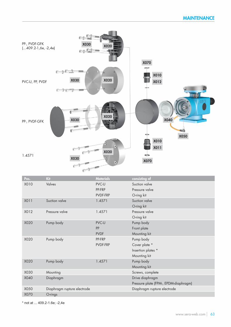
www.sera-web.com 63
MAINTENANCE
Pos. Kit Materials consisting ofX010 Valves PVC-U Suction valve
PP-FRP Pressure valvePVDF-FRP O-ring kit
X011 Suction valve 1.4571 Suction valveO-ring kit
X012 Pressure valve 1.4571 Pressure valveO-ring kit
X020 Pump body PVC-U Pump bodyPP Front platePVDF Mounting kit
X020 Pump body PP-FRP Pump bodyPVDF-FRP Cover plate *
Insertion plates *Mounting kit
X020 Pump body 1.4571 Pump bodyMounting kit
X030 Mounting Screws, completeX040 Diaphragm Drive diaphragm
Pressure plate (FPM-, EPDM-diaphragm)X050 Diaphragm rupture electrode Diaphragm rupture electrodeX070 O-rings
* not at ... 409.2-1.6e; -2,4e
PVC-U, PP, PVDF
PP-, PVDF-GFK
1.4571
X020
X010
X012
X010
X011
X070
X020
X020
X020
X030
X030
X030
X030
X040
X070
PP-, PVDF-GFK (...409.2-1,6e, -2,4e)
X050
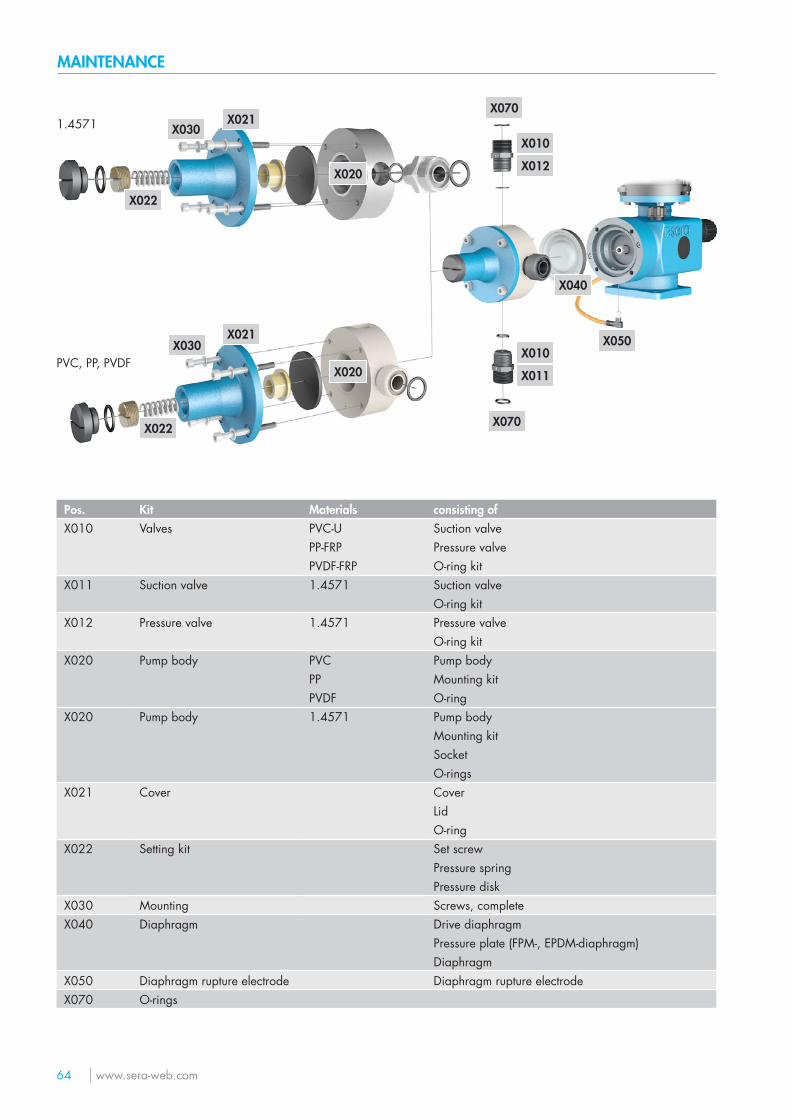
64 www.sera-web.com
MAINTENANCE
Pos. Kit Materials consisting ofX010 Valves PVC-U Suction valve
PP-FRP Pressure valvePVDF-FRP O-ring kit
X011 Suction valve 1.4571 Suction valveO-ring kit
X012 Pressure valve 1.4571 Pressure valveO-ring kit
X020 Pump body PVC Pump bodyPP Mounting kitPVDF O-ring
X020 Pump body 1.4571 Pump bodyMounting kitSocketO-rings
X021 Cover CoverLidO-ring
X022 Setting kit Set screwPressure springPressure disk
X030 Mounting Screws, completeX040 Diaphragm Drive diaphragm
Pressure plate (FPM-, EPDM-diaphragm)Diaphragm
X050 Diaphragm rupture electrode Diaphragm rupture electrodeX070 O-rings
X022
X030
X030
X021
X020
X010
X012
X010
X011
X070
X020
X040
X070
X021
X022
PVC, PP, PVDF
1.4571
X050
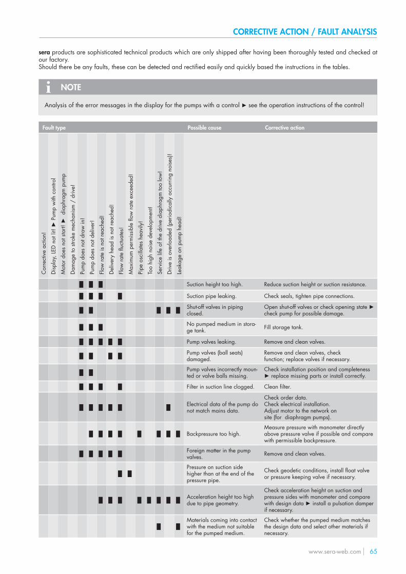
www.sera-web.com 65
CORRECTIVE ACTION / FAULT ANALYSIS
sera products are sophisticated technical products which are only shipped after having been thoroughly tested and checked at our factory.Should there be any faults, these can be detected and rectified easily and quickly based the instructions in the tables.
NOTE
Analysis of the error messages in the display for the pumps with a control ► see the operation instructions of the control!
Fault type Possible cause Corrective action
Cor
rect
ive
actio
n!
Disp
lay,
LED
not
lit!
► P
ump
with
con
trol
Mot
or d
oes
not s
tart!
► d
iaph
ragm
pum
p
Dam
age
to s
troke
mec
hani
sm /
driv
e!
Pum
p do
es n
ot d
raw
in!
Pum
p do
es n
ot d
eliv
er!
Flow
rate
is n
ot re
ache
d!
Del
iver
y he
ad is
not
reac
hed!
Flow
rate
fluc
tuat
es!
Max
imum
per
miss
ible
flow
rate
exc
eede
d!
Pipe
osc
illat
es h
eavi
ly!
Too
high
noi
se d
evel
opm
ent!
Serv
ice
life
of th
e dr
ive
diap
hrag
m to
o lo
w!
Driv
e is
over
load
ed (p
erio
dica
lly o
ccur
ring
noise
s)!
Leak
age
on p
ump
head
!
█ █ █ Suction height too high. Reduce suction height or suction resistance.
█ █ █ █ Suction pipe leaking. Check seals, tighten pipe connections.
█ █ █ █ █ Shut-off valves in pipingclosed.
Open shut-off valves or check opening state ► check pump for possible damage.
█ █ █ No pumped medium in stora-ge tank. Fill storage tank.
█ █ █ █ █ Pump valves leaking. Remove and clean valves.
█ █ █ █ Pump valves (ball seats)damaged.
Remove and clean valves, checkfunction; replace valves if necessary.
█ █ Pump valves incorrectly moun-ted or valve balls missing.
Check installation position and completeness ► replace missing parts or install correctly.
█ █ █ █ Filter in suction line clogged. Clean filter.
█ █ █ █ █ █ Electrical data of the pump donot match mains data.
Check order data.Check electrical installation.Adjust motor to the network onsite (for diaphragm pumps).
█ █ █ █ █ █ █ █ Backpressure too high.Measure pressure with manometer directly above pressure valve if possible and compare with permissible backpressure.
█ █ █ █ █ Foreign matter in the pumpvalves. Remove and clean valves.
█ █Pressure on suction side higher than at the end of the pressure pipe.
Check geodetic conditions, install float valve or pressure keeping valve if necessary.
█ █ █ █ █ █ █ █ Acceleration height too highdue to pipe geometry.
Check acceleration height on suction and pressure sides with manometer and compare with design data ► install a pulsation damper if necessary.
█ █Materials coming into contactwith the medium not suitable for the pumped medium.
Check whether the pumped medium matches the design data and select other materials if necessary.
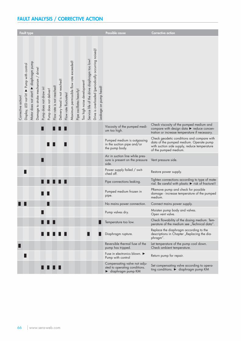
66 www.sera-web.com
FAULT ANALYSIS / CORRECTIVE ACTION
Fault type Possible cause Corrective action
Cor
rect
ive
actio
n!
Disp
lay,
LED
not
lit!
► P
ump
with
con
trol
Mot
or d
oes
not s
tart!
► d
iaph
ragm
pum
p
Dam
age
to s
troke
mec
hani
sm /
driv
e!
Pum
p do
es n
ot d
raw
in!
Pum
p do
es n
ot d
eliv
er!
Flow
rate
is n
ot re
ache
d!
Del
iver
y he
ad is
not
reac
hed!
Flow
rate
fluc
tuat
es!
Max
imum
per
miss
ible
flow
rate
exc
eede
d!
Pipe
osc
illat
es h
eavi
ly!
Too
high
noi
se d
evel
opm
ent!
Serv
ice
life
of th
e dr
ive
diap
hrag
m to
o lo
w!
Driv
e is
over
load
ed (p
erio
dica
lly o
ccur
ring
noise
s)!
Leak
age
on p
ump
head
!
█ █ █ █ Viscosity of the pumped medi-um too high.
Check viscosity of the pumped medium and compare with design data ► reduce concen-tration or increase temperature if necessary.
█ █ █Pumped medium is outgassingin the suction pipe and/orthe pump body.
Check geodetic conditions and compare with data of the pumped medium. Operate pump with suction side supply, reduce temperatureof the pumped medium.
█Air in suction line while pres-sure is present on the pressureside.
Vent pressure side.
█ Power supply failed / swit-ched off. Restore power supply.
█ █ █ █ █ Pipe connections leaking. Tighten connections according to type of mate-rial. Be careful with plastic ► risk of fracture!!
█ █ Pumped medium frozen inpipe.
PRemove pump and check for possible damage - increase temperature of the pumped medium.
█ █ █ No mains power connection. Connect mains power supply.
█ Pump valves dry. Moisten pump body and valves.Open vent valve.
█ █ █ █ Temperature too low. Check flowability of the dosing medium. Tem-perature of the medium see „Technical data“.
█ █ █ █ █ █ █ Diaphragm rupture.Replace the diaphragm according to the descriptions in Chapter „Replacing the dia-phragm“.
█ Reversible thermal fuse of thepump has tripped.
Let temperature of the pump cool down.Check ambient temperature.
█ Fuse in electronics blown. ► Pump with control Return pump for repair.
█ █ █ █Compensating valve not adju-sted to operating conditions. ► diaphragm pump KM
Set compensating valve according to opera-ting conditions. ► diaphragm pump KM
www.sera-web.com 67
SHUT-DOWN / DISPOSAL
Shut-down
■ Switch off piston diaphragm pump. ■ Rinse pump head and remove pumped medium; make sure that the rinsing agent is suitable for pumped medium and pump
head.
Disposal
■ Shut-down system. Please see “Shut-down“.
Dismantling and transport
■ Shut-down system. Please see “Shut-down“. ■ Remove all fluid residues from pump body, clean thoroughly, neutralize and decontaminate. ■ Package unit and ship.
NOTE
A clearance certificate must be filled in when systems are returned to the manufacturer.Acceptance will be rejected if this clearance certificate is not attached.
Complete disposal
■ Remove all fluid residues from unit. ■ Drain off lubricants and dispose of according to regulations! ■ Dismount materials and send them to a suitable waste disposal company!
WARNING
Observe and follow the safety instructions by all means.See the additional instructions „SAFETY INSTRUCTIONS“.Man, machine and environment are endangered if the safety instructions are not observed.
SI01
68 www.sera-web.com
NOTE
Inspection / repair of machines and machine parts is only carried out after the opposite clearance certificate was filled in correctly and completely by authorized and qualified personnel.
NOTE
Acceptance will be refused if parts are returned to the manufacturer without a proper clearance certificate.
All industrial companies are obligated by the legal provisions for occupational health, e.g. the workplaces ordinances, the Ordi-nance on Hazardous Substances, the regulations for prevention of accidents and the environmental protection regulations such as the Waste Management Act and the German Household Water Act to protect their employees or man and the environment from detrimental effects when handling hazardous substances.
Should special safety precautions be necessary despite careful draining and cleaning of the product the necessary information are to be provided.
Machines which are operated with radioactive media shall only be inspected and/or repaired in the safety area of the owner by a sera specialized fitter.
The clearance certificate is part of the inspection-/repair order. sera reserves the right to refuse acceptance of the order for other reasons.
NOTE
Please make a copy and leave the original with the operating instructions!(can also be downloaded from: www.sera-web.com)
CLEARANCE CERTIFICATE
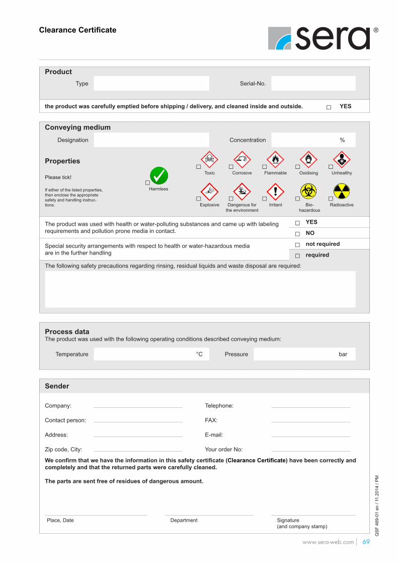
www.sera-web.com 69 1
Clearance Certificate
www.sera-web.com
QSF
469
-01
en /
11.2
014
/ PM
□
ProductType Serial-No.
the product was carefully emptied before shipping / delivery, and cleaned inside and outside. □ YES
Conveying mediumDesignation Concentration %
Properties
Please tick!
If either of the listed properties, then enclose the appropriate safety and handling instruc-tions.
The product was used with health or water-polluting substances and came up with labeling requirements and pollution prone media in contact.
□ YES
□ NO
Special security arrangements with respect to health or water-hazardous mediaare in the further handling
□ not required
□ required
The following safety precautions regarding rinsing, residual liquids and waste disposal are required:
Process dataThe product was used with the following operating conditions described conveying medium:
Temperature °C Pressure bar
Sender
Company: Telephone:
Contact person: FAX:
Address: E-mail:
Zip code, City: Your order No:
We confirm that we have the information in this safety certificate (Clearance Certificate) have been correctly and completely and that the returned parts were carefully cleaned. The parts are sent free of residues of dangerous amount.
Place, Date Department Signature(and company stamp)
□Corrosive
□Flammable
□Oxidising
□Unhealthy
□Toxic
□Harmless
□Dangerous for
the environment
□Bio-
hazardous
□Radioactive
□Explosive
□Irritant
TM01
-04
EN
200
107
sera
® is
a re
giste
red
trade
mar
k of
ser
a G
mbH
. Te
chni
cal d
etai
ls su
bjec
t to
chan
ge. s
era
shal
l not
acc
ept a
ny li
abili
ty fo
r erro
rs o
r om
issio
ns o
r for
prin
ting
erro
rs.
FOLLOW US
sera ProDos GmbHsera-Str. 134376 ImmenhausenGermanyTel. +49 5673 999 02Fax +49 5673 999 [email protected]