Embed Size (px)
Citation preview
Canplas® Endura® Grease Management I
T E C H N I C A L M A N UA L
H Y D R O M E C H A N I C A L G R E A S E I N T E R C E P T O R S ( H G I )
7 to 50 GPM Models
XL 75 to 150 GPM Models
XL Sampling Well
Solids Interceptors
Rethinking Grease Interception
e n d u r a i n t e r c e p t o r . c o m
II Canplas® Endura® Grease Management
Endura® Grease Management
Technical Manual
© 2021 by Canplas®. All rights reserved. No part of this book may
be used or reproduced in any manner whatsoever without prior
written permission. For information contact: Canplas Industries Ltd.
500 Veterans Drive, Box 1800 Barrie, Ontario, Canada L4M 4V3
The information contained here within is based on current information and product design at the time of publication and is subject to change without notification. Canplas does not guarantee or warranty the accuracy, suitability for particular applications, or results to be obtained therefrom.
Canplas® Endura® Grease Management III
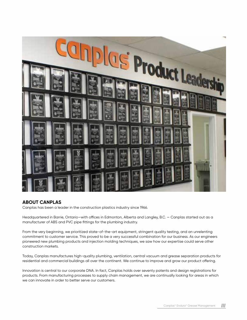
ABOUT CANPLAS Canplas has been a leader in the construction plastics industry since 1966.
Headquartered in Barrie, Ontario—with offices in Edmonton, Alberta and Langley, B.C. — Canplas started out as a
manufacturer of ABS and PVC pipe fittings for the plumbing industry.
From the very beginning, we prioritized state-of-the-art equipment, stringent quality testing, and an unrelenting
commitment to customer service. This proved to be a very successful combination for our business. As our engineers
pioneered new plumbing products and injection molding techniques, we saw how our expertise could serve other
construction markets.
Today, Canplas manufactures high-quality plumbing, ventilation, central vacuum and grease separation products for
residential and commercial buildings all over the continent. We continue to improve and grow our product offering.
Innovation is central to our corporate DNA. In fact, Canplas holds over seventy patents and design registrations for
products. From manufacturing processes to supply chain management, we are continually looking for areas in which
we can innovate in order to better serve our customers.
IV Canplas® Endura® Grease Management
Endura® Grease Management products are an effective, efficient and trusted component of our injection molded product family and have demonstrated exceptional performance over the decades.
Endura products are multi-patented and built to withstand the toughest environments, providing the flexibility of in-floor, on-floor, and semi-recessed applications. We have been instrumental in changing the traditional practices regarding the installation of grease management solutions; plastic alternatives to metal interceptors are now substantially accepted Nationwide as the new standard for grease management in commercial foodservice applications.
Endura products are thermoplastic Hydromechanical grease interceptor (HGI) designed to provide exceptional grease management solutions for plumbing and food service professionals. HGIs are manufactured in an ISO 9001 and 14001 registered facility. Sizes range from 7 through to 150 GPM units constructed of either Polypropylene (PP) or Polyethylene (PE) compound.
This manual provides installers, designers and engineers with guidance to help ensure the proper usage of Endura products. Readers are encouraged to consult with the Manufacturer or local representative for any additional clarification before using Endura to ensure a successful installation.
At Endura, we think the best way to protect municipalities and our waterways is to put proactive interception practices into place. It’s about more than providing better technology and materials—it’s about rethinking the entire process. From installation, to maintenance, to durability, we provide a complete solution that is both innovative and proactive.
If you need additional copies of any instructions, or if you have questions about the safe and proper installation of
Endura products, contact Endura Toll Free (Canada: 1-800-461-1771) or (USA: 1-888-461-5307).For the most up-to-date information on Endura products,
email: [email protected]
Canplas® Endura® Grease Management V
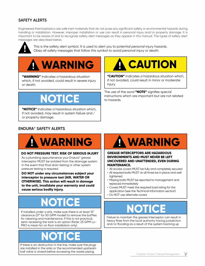
As a plumbing appurtenance your Endura® grease interceptor MUST be isolated from the drainage system in the event that final drain testing or other system pressure testing is required.
DO NOT under any circumstances subject your interceptor to pressure test (AIR, WATER OR OTHERWISE). This action will result in damage to the unit, invalidate your warranty and could cause serious bodily injury.
NOTICE
DO NOT PRESSURE TEST. RISK OF SERIOUS INJURY
WARNINGWARNINGGREASE INTERCEPTORS ARE HAZARDOUS ENVIRONMENTS AND MUST NEVER BE LEFT UNCOVERED AND UNATTENDED, EVEN DURING MAINTENANCE. • All access covers MUST be fully and completely secured• All required bolts MUST at all times be in place and well tightened• Missing bolts MUST be reported to management and replaced immediately• Covers MUST meet the required load rating for the application (see the Technical Information section)• Do NOT use alternate covers
If installed under a sink, make sure there is at least 15” clearance (21” for 50 GPM model) to remove the baffles for cleaning and maintenance. If this is not practical, semi-recessing the tank is an option (Note: 25 GPM Lo-PRO is mean for on floor installation only).
NOTICE
NOTICEFailure to maintain the grease Interceptor can result in heavy fines from the local authority having jurisdiction and/or flooding as a result of the system backing up
If there is an obstruction in the line, make sure the plugs are installed in the sinks or the recommended upstream ball valve is closed before accessing the waste piping.
This is the safety alert symbol. It is used to alert you to potential personal injury hazards. Obey all safety messages that follow this symbol to avoid personal injury or death.
The use of the word “NOTE” signifies special instructions which are important but are not related to hazards.
CAUTION“CAUTION” Indicates a hazardous situation which, if not avoided, could result in minor or moderate injury.
NOTICE“NOTICE” Indicates a hazardous situation which, if not avoided, may result in system failure and / or property damage.
SAFETY ALERTS
Engineered thermoplastics are safe inert materials that do not pose any significant safety or environmental hazards during handling or installation. However, improper installation or use can result in personal injury and/or property damage. It is important to be aware of and to recognize safety alert messages as they appear in this manual. The types of safety alert messages are described below.
ENDURA® SAFETY ALERTS
WARNING“WARNING” Indicates a hazardous situation which, if not avoided, could result in severe injury or death.
VI Canplas® Endura® Grease Management
Endura® Grease Management Plumbing Systems
About Canplas III
Safety Alerts V
Section 1: General Information
Overview 01
How Does It Work 02
Features And Benefits 03
Section 2: System Design
Design Considerations 04
Materials 04
Layout 04
Operating Temperature 04
Chemical Resistance 04
Monitoring 04
Flow Control 05
Connection Of Dishwashing Systems 06
Air-Balanced Operation 06
Venting 06
Drain Cleanouts 06
Head Effect 06
Accessibility For Maintenance 06
Sampling Access 06
Indirect Connection / Air Gap / Air Break 06
Sizing For Grease Capacity & Maintenance 07
Section 3: Product Data
Product Data 12
Dimensions 13
CONTENTS
Canplas® Endura® Grease Management VII
Section 4: Installation
Installation Overview 18
Endura 7 to 50 GPM Models - Typical Installation Examples 19
Endura 7 to 50 GPM Models - Installation Instructions 22
Endura XL 75 To 150 GPM Models - Typical Installation Examples 24
Endura XL 75 to 150 GPM Models - Multi Unit Examples 26
Endura XL 75 to 150 GPM Models - Installation Instructions 28
Endura Extension Risers/ Risers 15 to 50 GPM Models 31
Endura XL Extension Risers/ Risers 34
Endura XL Remote Pump 39
Endura XL Sampling Well 40
Endura XL Sampling Well with Cast Iron Cover 42
Endura Solids Interceptors 46
Endura Solids Accessory Basket 48
Section 5: System Operation, Maintenance And Repairs
General Operation And Maintenance 49
Maintenance Procedures 7-50 GPM 51
Maintenance Procedures 75-150 GPM 52
Maintenance Procedures Endura Solids Interceptor 54
Section 6: Frequently Asked Questions And Troubleshooting 55
Section 7: Specifications 57
Section 8: Warranty
Endura Limited Lifetime Warranty 58
1 Canplas® Endura® Grease Management
GE
NE
RA
L IN
FO
RM
AT
ION
OVERVIEW
The grease management industry has developed significantly in the past decade with the continuous advancement of product design, progression of performance standards, and the emergence of HGIs as a mainstream, progressive solution for the future.
Traditionally, the term “Grease Trap” has been used in the industry. In recent years this term is progressively disappearing from vocabulary and technical references based on an industry-wide recognition that the term “trap” would suggest the presence of a water seal integrally located within the interceptor, leading to potential confusion of the function of a grease interceptor. This practice ceased many years ago, modern interceptors being designed to be installed in conjunction with external water seal traps as a standard part of the system.
In addition to this clarification, with publication of the 2006 UPC plumbing code, three generic types of grease interceptors were introduced and have since become the industry standard for designating the type of interceptor being considered.
GREASE INTERCEPTOR (GI): “A plumbing appurtenance or appliance that is installed in a sanitary drainage system to intercept nonpetroleum fats, oil, and grease (FOG) from a wastewater discharge.”
Specific characteristics further classify GI’s into one of the three types:
HYDROMECHANICAL GREASE INTERCEPTOR (HGI):An HGI is sized by flow rate (GPM) and qualified separation/retention efficiency, validated against National performance Standards. An HGI incorporates a defined means of flow control, acts to entrain air to influent, includes interior baffling, or barriers in combination or separately, working to promote hydromechanical separation. HGI’s may be installed inside the facility they serve or outside the building, above or below grade.
GRAVITY GREASE INTERCEPTOR (GGI):A GGI is characterized by volume, minimum 20 minute retention time, baffle(s), not less than two compartments, a total volume of not less than 350 gallons, and gravity separation. If not recognized by an official body, a GGI will be designed by a registered professional engineer. GGI’s are generally installed outside the building they serve and buried
below grade.
GREASE REMOVAL DEVICE (GRD):A GRD is a hydromechanical grease interceptor that mechanically removes nonpetroleum FOG from the separation chamber, the control of which is either automatic or manually initiated and involves maintaining a liquefied state of intercepted FOG by heating. GRD’s are installed inside the facility they serve.
SECTION ONE: GENERAL INFORMATION
Canplas® Endura® Grease Management 2
GE
NE
RA
L IN
FO
RM
AT
ION
Selection of the appropriate size HGI is critical to the performance of the system. HGIs are sized based on flow rate and their grease carrying capacity. Flow control devices must be installed per plumbing code to ensure the waterflow does not exceed the certified flow rate of the HGI. HGI’s are performance tested to National Standards (such as PDI G-101, ASME A112.14.3, CSA B481) offering the end user confidence that the minimum level of efficiency will be achieved.
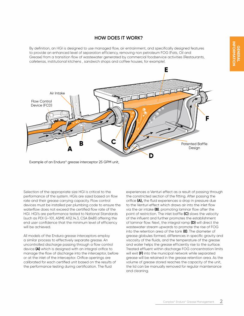
All models of the Endura grease interceptors employ a similar process to effectively separate grease. An uncontrolled discharge passing through a flow control device (A) which is designed with an integral orifice to manage the flow of discharge into the interceptor, before or at the inlet of the interceptor. Orifice openings are calibrated for each certified unit based on the results of the performance testing during certification. The fluid
experiences a Venturi effect as a result of passing through the constricted section of the fitting. After passing the orifice (A), the fluid experiences a drop in pressure due to the Venturi effect which draws air into the inlet flow via the air intake (B), promoting laminar flow after the point of restriction. The inlet baffle (C) slows the velocity of the influent and further promotes the establishment of laminar flow. Next, the integral ramp (D) will direct the wastewater stream upwards to promote the rise of FOG into the retention area of the tank (E). The diameter of grease globules formed, differences in specific gravity and viscosity of the fluids, and the temperature of the grease and water helps the grease efficiently rise to the surface. Treated effluent within discharge FOG concentration limits will exit (F) into the municipal network while separated grease will be retained in the grease retention area. As the volume of grease stored reaches the capacity of the unit, the lid can be manually removed for regular maintenance and cleaning.
HOW DOES IT WORK?
By definition, an HGI is designed to use managed flow, air entrainment, and specifically designed features to provide an enhanced level of separation efficiency, removing non petroleum FOG (Fats, Oil and Grease) from a transition flow of wastewater generated by commercial foodservice activities (Restaurants, cafeterias, institutional kitchens , sandwich shops and coffee houses, for example).
Example of an Endura® grease interceptor 25 GPM unit,
Flow Control Device (FCD)
AB C
D
E
F
Air Intake
Patented Baffle Design
3 Canplas® Endura® Grease Management
GE
NE
RA
L IN
FO
RM
AT
ION
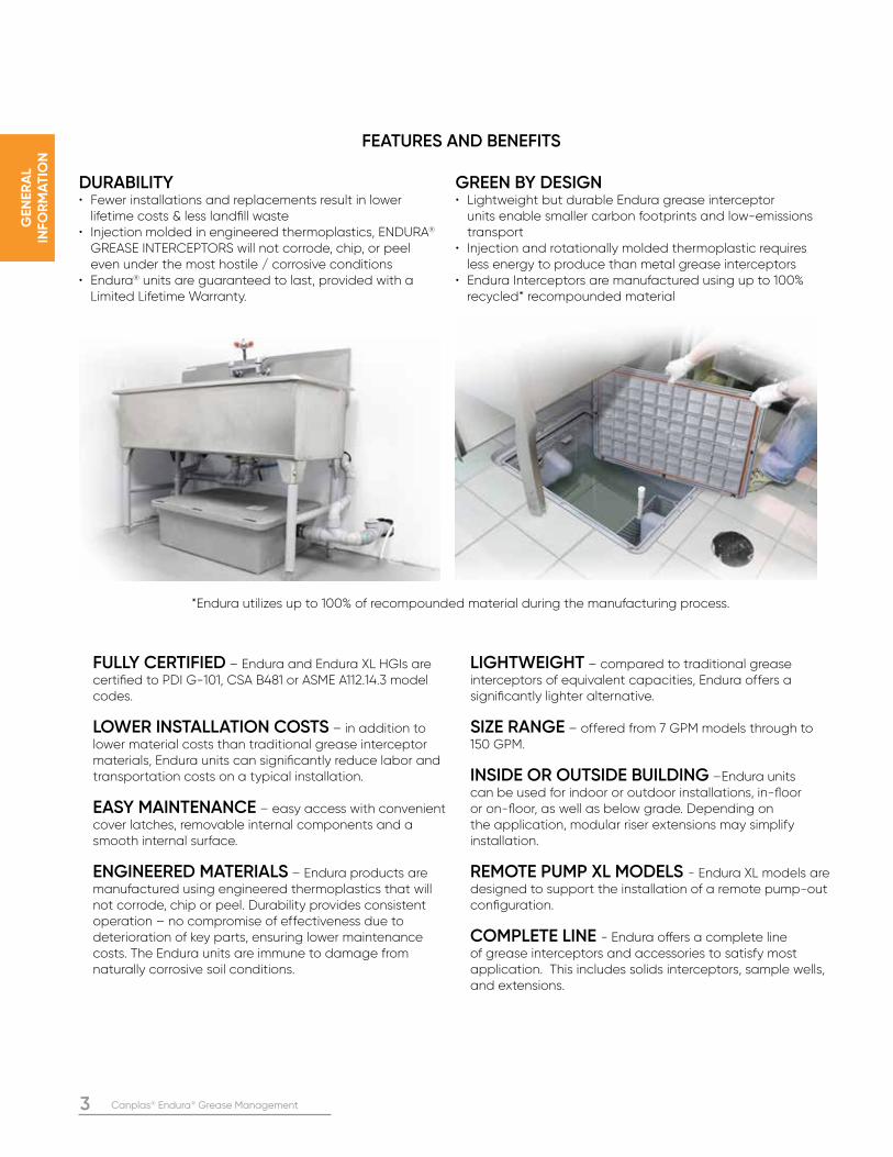
DURABILITY• Fewer installations and replacements result in lower lifetime costs & less landfill waste• Injection molded in engineered thermoplastics, ENDURA® GREASE INTERCEPTORS will not corrode, chip, or peel even under the most hostile / corrosive conditions• Endura® units are guaranteed to last, provided with a Limited Lifetime Warranty.
FULLY CERTIFIED – Endura and Endura XL HGIs are certified to PDI G-101, CSA B481 or ASME A112.14.3 model codes.
LOWER INSTALLATION COSTS – in addition to lower material costs than traditional grease interceptor materials, Endura units can significantly reduce labor and transportation costs on a typical installation.
EASY MAINTENANCE – easy access with convenient cover latches, removable internal components and a smooth internal surface.
ENGINEERED MATERIALS – Endura products are manufactured using engineered thermoplastics that will not corrode, chip or peel. Durability provides consistent operation – no compromise of effectiveness due to deterioration of key parts, ensuring lower maintenance costs. The Endura units are immune to damage from naturally corrosive soil conditions.
LIGHTWEIGHT – compared to traditional grease interceptors of equivalent capacities, Endura offers a significantly lighter alternative.
SIZE RANGE – offered from 7 GPM models through to 150 GPM.
INSIDE OR OUTSIDE BUILDING –Endura units can be used for indoor or outdoor installations, in-floor or on-floor, as well as below grade. Depending on the application, modular riser extensions may simplify installation.
REMOTE PUMP XL MODELS - Endura XL models are designed to support the installation of a remote pump-out configuration.
COMPLETE LINE - Endura offers a complete line of grease interceptors and accessories to satisfy most application. This includes solids interceptors, sample wells, and extensions.
GREEN BY DESIGN• Lightweight but durable Endura grease interceptor units enable smaller carbon footprints and low-emissions transport• Injection and rotationally molded thermoplastic requires less energy to produce than metal grease interceptors• Endura Interceptors are manufactured using up to 100% recycled* recompounded material
*Endura utilizes up to 100% of recompounded material during the manufacturing process.
FEATURES AND BENEFITS
Canplas® Endura® Grease Management 4
SY
ST
EM
D
ES
IGN
DESIGN CONSIDERATIONS
Endura is solely intended for use in non petroleum grease management and separation.
MATERIAL:All Endura grease interceptors are designed to meet or exceed material standards as published in PDI G-101, CSA B481 and ASME A112.14.3.
Both materials allow for the units to be used in below grade applications due to their superior resistance to harsh conditions in soil.
PP (Polypropylene) Endura 7 GPM to 50 GPMPP offers high operating temperatures 220˚F (104˚C) making it ideal for point of use applications. PP also offers strong chemical and corrosion resistance from food waste. It is capable of handling a pH ranging from 1 to 13, and is resistant to organic solvents as well as acids and alkalis.
CHEMICAL RESISTANCEOver time as grease collects in the interceptor, the FOG breaks down. Anaerobic bacteria convert the naturally occurring sulfate molecules into sulfides. The sulfides later form hydrogen sulfide gas (H2S), which is a toxic and corrosive colorless gas with a characteristic foul odor of rotten eggs. Furthermore, airborne aerobic bacteria consume hydrogen sulfide gas, generating sulfuric acid (H2SO4) in the wastewater of the interceptor. PP and PE have outstanding resistance to a wide range of chemicals including hydrogen sulfide and sulfuric acid making the materials an ideal choice for these applications.
PE (Polyethylene) Endura XL 75 - 150 GPM modelsPE tolerates high operating temperatures 160˚F (71˚C),PE also offers strong chemical and corrosion resistance from food waste. It is capable of handling a pH ranging from 1 to 13, and is resistant to organic solvents as well as acids and alkalis.
LAYOUTDependent on the specific grease interceptor model,installation can be indoor or outdoor, above or belowground. It is recommended to have your greaseinterceptor unit within 25ft (7.6m) of the last sink(discharge fixture). Pipe runs longer than 25ft should be aggressively sloped and/or heat traced to help prevent FOG from building up in the piping system. Access to effluent for sampling may be required by AHJs in some jurisdictions. A sample well may be installed downstream of the grease interceptor to facilitate access. Refer to the examples of typical installations within section 3 of this manual for more detail.
MONITORINGTo simplify maintenance, the Endura XL Grease Monitor and Alarm can be installed to alert operators when it is time to schedule service. It also safeguards the food service facility by monitoring for high liquid level events,
which may signal a blockage or impending backup.
SECTION TWO: SYSTEM DESIGN
5 Canplas® Endura® Grease Management
SY
ST
EM
D
ES
IGN
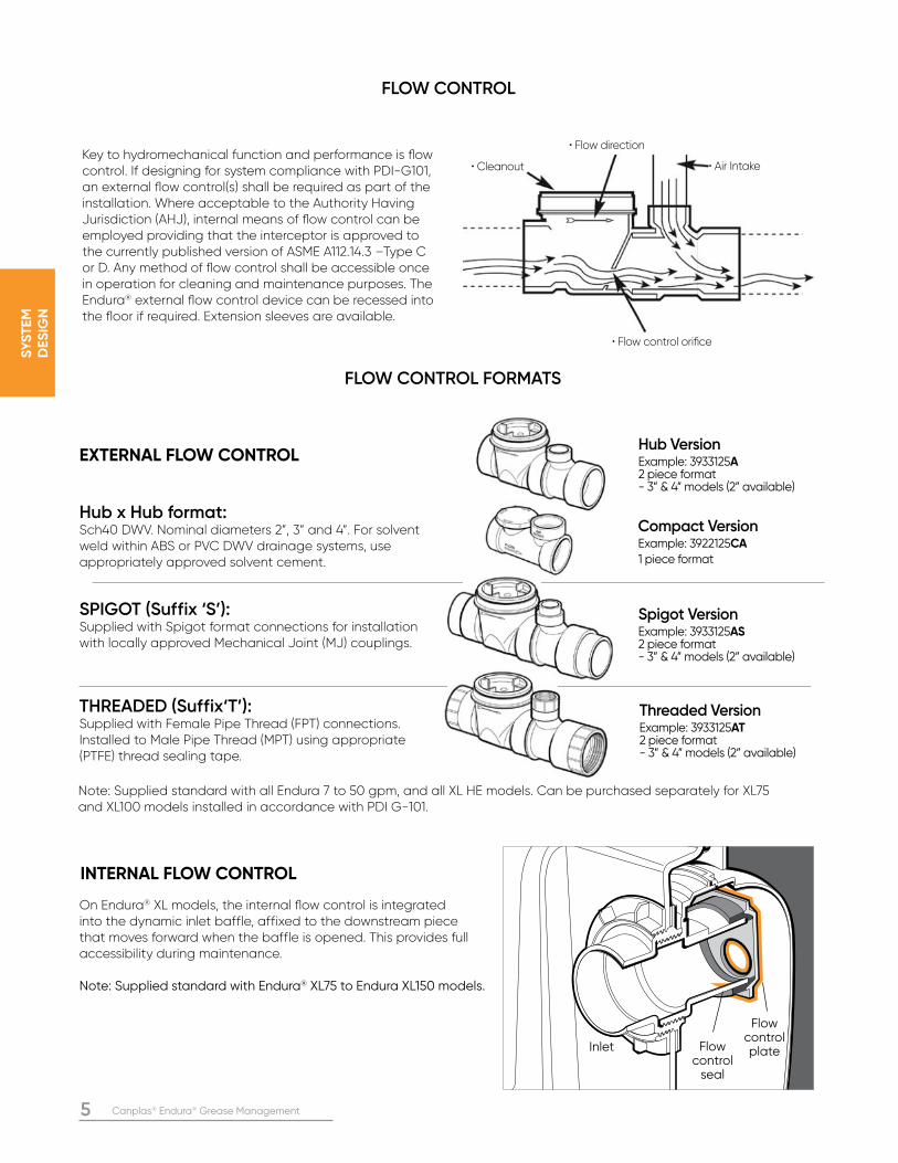
• Flow direction
• Air Intake• Cleanout
• Flow control orifice
FLOW CONTROL
FLOW CONTROL FORMATS
Key to hydromechanical function and performance is flow control. If designing for system compliance with PDI-G101, an external flow control(s) shall be required as part of the installation. Where acceptable to the Authority Having Jurisdiction (AHJ), internal means of flow control can be employed providing that the interceptor is approved to the currently published version of ASME A112.14.3 –Type C or D. Any method of flow control shall be accessible once in operation for cleaning and maintenance purposes. The Endura® external flow control device can be recessed into the floor if required. Extension sleeves are available.
Hub x Hub format: Sch40 DWV. Nominal diameters 2”, 3” and 4”. For solvent weld within ABS or PVC DWV drainage systems, use appropriately approved solvent cement.
SPIGOT (Suffix ‘S’): Supplied with Spigot format connections for installation with locally approved Mechanical Joint (MJ) couplings.
THREADED (Suffix‘T’): Supplied with Female Pipe Thread (FPT) connections. Installed to Male Pipe Thread (MPT) using appropriate (PTFE) thread sealing tape.
Compact VersionExample: 3922125CA1 piece format
Spigot Version Example: 3933125AS2 piece format - 3” & 4” models (2” available)
Threaded Version Example: 3933125AT2 piece format - 3” & 4” models (2” available)
Hub VersionExample: 3933125A2 piece format - 3” & 4” models (2” available)
Flow control plateFlow
control seal
Inlet
On Endura® XL models, the internal flow control is integrated into the dynamic inlet baffle, affixed to the downstream piece that moves forward when the baffle is opened. This provides full accessibility during maintenance.
Note: Supplied standard with Endura® XL75 to Endura XL150 models.
INTERNAL FLOW CONTROL
EXTERNAL FLOW CONTROL
Note: Supplied standard with all Endura 7 to 50 gpm, and all XL HE models. Can be purchased separately for XL75 and XL100 models installed in accordance with PDI G-101.
Canplas® Endura® Grease Management 6
SY
ST
EM
D
ES
IGN
CONNECTION OF DISHWASHING SYSTEMS Local plumbing code may require or prohibit a dishwasher discharging into a grease interceptor. Where a dishwashing system is required to discharge into the grease interceptor, it is recommended that it be serviced by a dedicated grease interceptor, separate from the main interceptor.
AIR-BALANCED OPERATION A hydromechanical grease interceptor is designed to operate as an air balanced environment. This is vital to the function of the interceptor. No modification or removal of any component parts should be made before, during or after installation unless specifically addressed in the respective Installation & Operation document.
VENTINGGrease interceptors must have a vented waste sized in accordance with local code requirements with local requirements to retain a water seal to retain a water seal and prevent siphoning. Endura grease interceptor tanks do not require direct venting.
Most codes dictate that two vents be installed, one upstream and one downstream of the grease interceptor. All connected appliances shall be individually trapped and vented in accordance with local code requirements. The upstream vent must not be placed between the air intake and the grease interceptor. The downstream drain carrying effluent to the municipal wastewater system shall also be vented to atmosphere in compliance with applicable code.
CLEANOUTS For installations below grade, most codes require the installation of a two way cleanout immediately before and after the respective inlet and outlet connections. These cleanouts will be extended to grade to remain accessible once the interceptor is operational.
HEAD EFFECTAn installation above or below grade that sees a fall equal to or in excess of 10 ft (3.05 m), when measured from the outlet of the highest appliance to the inlet of the interceptor will require the installation of a secondary flow control device to neutralize the effect of head pressure. The first flow control will be located as close as possible to the last appliance discharging to the interceptor, the second being located immediately before the interceptor or by utilizing the manufacturers internal flow control device where available. Refer to your local plumbing and building code for any regionally specific requirements.
ACCESSIBILITY FOR MAINTENANCEAll grease interceptors require regular maintenance. All designs and subsequent installations must ensure that accessibility will be maintained throughout the operation of the interceptor. Installation documents are supplied with every interceptor. Copies are also available by contacting: [email protected]
SAMPLING ACCESSSome municipalities require a sampling port to monitor effluent quality. Any design and subsequent installation should ensure that sampling access is incorporated in accordance with local requirements.
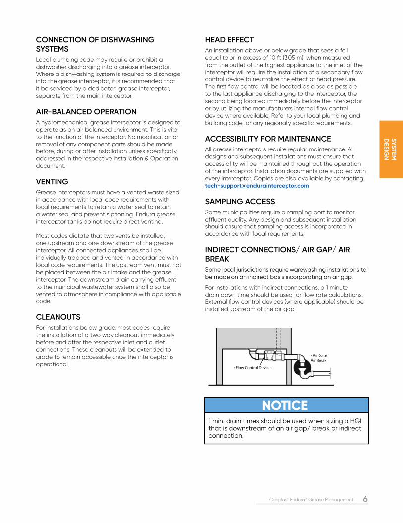
INDIRECT CONNECTIONS/ AIR GAP/ AIR BREAKSome local jurisdictions require warewashing installations to be made on an indirect basis incorporating an air gap.
For installations with indirect connections, a 1 minute drain down time should be used for flow rate calculations. External flow control devices (where applicable) should be installed upstream of the air gap.
NOTICE1 min. drain times should be used when sizing a HGI that is downstream of an air gap/ break or indirect connection.
• Air Gap/ Air Break
• Flow Control Device
7 Canplas® Endura® Grease Management
SY
ST
EM
D
ES
IGN
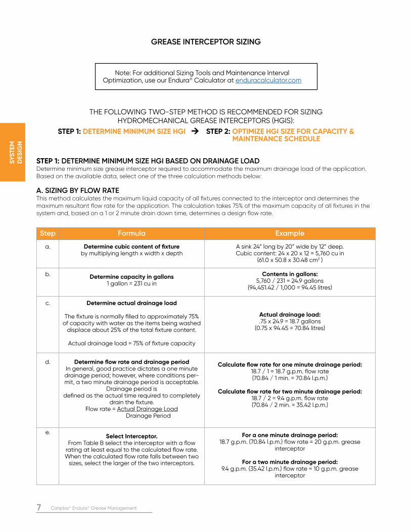
Step Formula Example
a. Determine cubic content of fixture by multiplying length x width x depth
A sink 24” long by 20” wide by 12” deep.Cubic content: 24 x 20 x 12 = 5,760 cu in
(61.0 x 50.8 x 30.48 cm3 )
b. Determine capacity in gallons 1 gallon = 231 cu in
Contents in gallons:5,760 / 231 = 24.9 gallons
(94,451.42 / 1,000 = 94.45 litres)
c. Determine actual drainage load
The fixture is normally filled to approximately 75% of capacity with water as the items being washed
displace about 25% of the total fixture content.
Actual drainage load = 75% of fixture capacity
Actual drainage load:.75 x 24.9 = 18.7 gallons
(0.75 x 94.45 = 70.84 litres)
d. Determine flow rate and drainage periodIn general, good practice dictates a one minute drainage period; however, where conditions per-mit, a two minute drainage period is acceptable.
Drainage period is defined as the actual time required to completely
drain the fixture.Flow rate = Actual Drainage Load
Drainage Period
Calculate flow rate for one minute drainage period:18.7 / 1 = 18.7 g.p.m. flow rate(70.84 / 1 min. = 70.84 l.p.m.)
Calculate flow rate for two minute drainage period:18.7 / 2 = 9.4 g.p.m. flow rate(70.84 / 2 min. = 35.42 l.p.m.)
e.Select Interceptor.
From Table B select the interceptor with a flow rating at least equal to the calculated flow rate. When the calculated flow rate falls between two
sizes, select the larger of the two interceptors.
For a one minute drainage period:18.7 g.p.m. (70.84 l.p.m.) flow rate = 20 g.p.m. grease
interceptor
For a two minute drainage period:9.4 g.p.m. (35.42 l.p.m.) flow rate = 10 g.p.m. grease
interceptor
GREASE INTERCEPTOR SIZING
THE FOLLOWING TWO-STEP METHOD IS RECOMMENDED FOR SIZING HYDROMECHANICAL GREASE INTERCEPTORS (HGIS):
STEP 1: DETERMINE MINIMUM SIZE HGI → STEP 2: OPTIMIZE HGI SIZE FOR CAPACITY & MAINTENANCE SCHEDULE
STEP 1: DETERMINE MINIMUM SIZE HGI BASED ON DRAINAGE LOADDetermine minimum size grease interceptor required to accommodate the maximum drainage load of the application. Based on the available data, select one of the three calculation methods below:
A. SIZING BY FLOW RATEThis method calculates the maximum liquid capacity of all fixtures connected to the interceptor and determines the maximum resultant flow rate for the application. The calculation takes 75% of the maximum capacity of all fixtures in the system and, based on a 1 or 2 minute drain down time, determines a design flow rate.
Note: For additional Sizing Tools and Maintenance Interval Optimization, use our Endura® Calculator at enduracalculator.com
Canplas® Endura® Grease Management 8
SY
ST
EM
D
ES
IGN
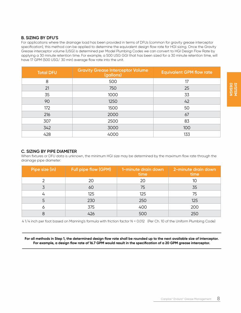
B. SIZING BY DFU’SFor applications where the drainage load has been provided in terms of DFUs (common for gravity grease interceptor specification), this method can be applied to determine the equivalent design flow rate for HGI sizing. Once the Gravity Grease interceptor volume (USG) is determined per Model Plumbing Codes we can convert to HGI Design Flow Rate by applying a 30 minute retention time. For example, a 500 USG GGI that has been sized for a 30 minute retention time, will have 17 GPM (500 USG/ 30 min) average flow rate into the unit.
C. SIZING BY PIPE DIAMETERWhen fixtures or DFU data is unknown, the minimum HGI size may be determined by the maximum flow rate through the drainage pipe diameter:
4 1/4 inch per foot based on Manning’s formula with friction factor N = 0.012 (Per Ch. 10 of the Uniform Plumbing Code)
For all methods in Step 1, the determined design flow rate shall be rounded up to the next available size of interceptor. For example, a design flow rate of 16.7 GPM would result in the specification of a 20 GPM grease interceptor.
Total DFUGravity Grease Interceptor Volume
(gallons)Equivalent GPM flow rate
8 500 17
21 750 25
35 1000 33
90 1250 42
172 1500 50
216 2000 67
307 2500 83
342 3000 100
428 4000 133
Pipe size (in) Full pipe flow (GPM) 1-minute drain down time
2-minute drain down time
2 20 20 10
3 60 75 35
4 125 125 75
5 230 250 125
6 375 400 200
8 426 500 250
9 Canplas® Endura® Grease Management
SY
ST
EM
D
ES
IGN
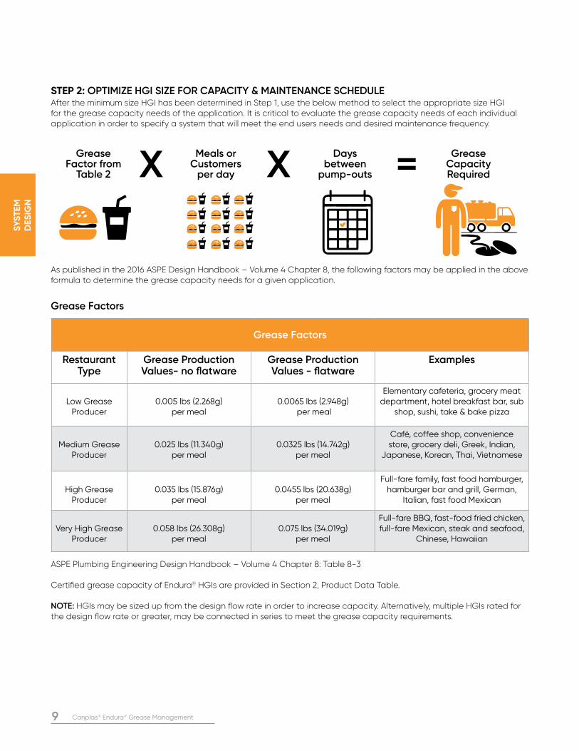
STEP 2: OPTIMIZE HGI SIZE FOR CAPACITY & MAINTENANCE SCHEDULEAfter the minimum size HGI has been determined in Step 1, use the below method to select the appropriate size HGI for the grease capacity needs of the application. It is critical to evaluate the grease capacity needs of each individual application in order to specify a system that will meet the end users needs and desired maintenance frequency.
As published in the 2016 ASPE Design Handbook – Volume 4 Chapter 8, the following factors may be applied in the above formula to determine the grease capacity needs for a given application.
GreaseFactor from
Table 2
Meals or Customers
per day
Days between
pump-outs
Grease Capacity RequiredX X =
ASPE Plumbing Engineering Design Handbook – Volume 4 Chapter 8: Table 8-3
Certified grease capacity of Endura® HGIs are provided in Section 2, Product Data Table.
NOTE: HGIs may be sized up from the design flow rate in order to increase capacity. Alternatively, multiple HGIs rated for the design flow rate or greater, may be connected in series to meet the grease capacity requirements.
Grease Factors
Restaurant Type
Grease Production Values- no flatware
Grease Production Values - flatware
Examples
Low Grease Producer
0.005 lbs (2.268g) per meal
0.0065 lbs (2.948g) per meal
Elementary cafeteria, grocery meat department, hotel breakfast bar, sub
shop, sushi, take & bake pizza
Medium Grease Producer
0.025 lbs (11.340g) per meal
0.0325 lbs (14.742g) per meal
Café, coffee shop, convenience store, grocery deli, Greek, Indian,
Japanese, Korean, Thai, Vietnamese
High Grease Producer
0.035 lbs (15.876g) per meal
0.0455 lbs (20.638g) per meal
Full-fare family, fast food hamburger, hamburger bar and grill, German,
Italian, fast food Mexican
Very High Grease Producer
0.058 lbs (26.308g) per meal
0.075 lbs (34.019g) per meal
Full-fare BBQ, fast-food fried chicken, full-fare Mexican, steak and seafood,
Chinese, Hawaiian
Grease Factors
Canplas® Endura® Grease Management 10
SY
ST
EM
D
ES
IGN
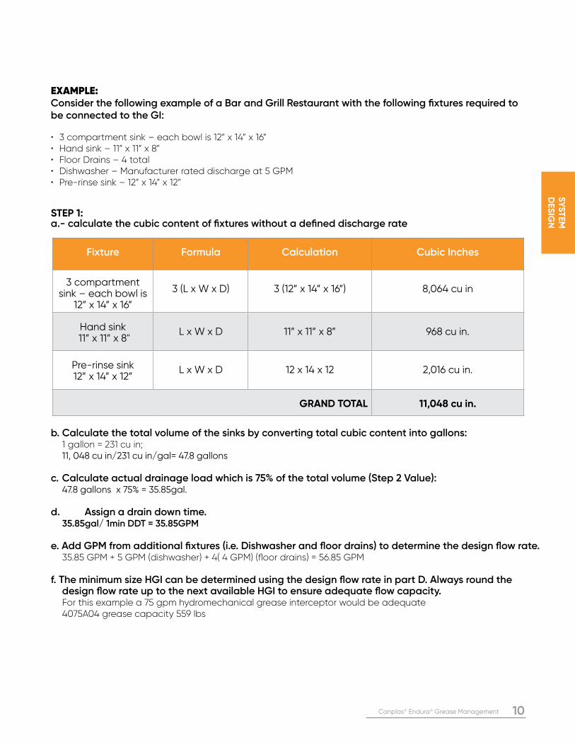
EXAMPLE: Consider the following example of a Bar and Grill Restaurant with the following fixtures required to be connected to the GI:
• 3 compartment sink – each bowl is 12” x 14” x 16”• Hand sink – 11” x 11” x 8”• Floor Drains – 4 total• Dishwasher – Manufacturer rated discharge at 5 GPM• Pre-rinse sink – 12” x 14” x 12”
STEP 1: a.- calculate the cubic content of fixtures without a defined discharge rate
b. Calculate the total volume of the sinks by converting total cubic content into gallons: 1 gallon = 231 cu in; 11, 048 cu in/231 cu in/gal= 47.8 gallons
c. Calculate actual drainage load which is 75% of the total volume (Step 2 Value): 47.8 gallons x 75% = 35.85gal. d. Assign a drain down time. 35.85gal/ 1min DDT = 35.85GPM e. Add GPM from additional fixtures (i.e. Dishwasher and floor drains) to determine the design flow rate. 35.85 GPM + 5 GPM (dishwasher) + 4( 4 GPM) (floor drains) = 56.85 GPM f. The minimum size HGI can be determined using the design flow rate in part D. Always round the design flow rate up to the next available HGI to ensure adequate flow capacity. For this example a 75 gpm hydromechanical grease interceptor would be adequate 4075A04 grease capacity 559 lbs
Fixture Formula Calculation Cubic Inches
3 compartment sink – each bowl is
12” x 14” x 16”
3 (L x W x D) 3 (12” x 14” x 16”) 8,064 cu in
Hand sink 11” x 11” x 8"
L x W x D 11” x 11” x 8” 968 cu in.
Pre-rinse sink 12” x 14” x 12”
L x W x D 12 x 14 x 12 2,016 cu in.
GRAND TOTAL 11,048 cu in.
11 Canplas® Endura® Grease Management
SY
ST
EM
D
ES
IGN
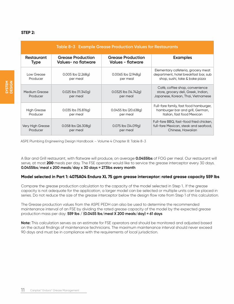
STEP 2:
A Bar and Grill restaurant, with flatware will produce, on average 0.0455lbs of FOG per meal. Our restaurant will serve, at most 200 meals per day. The FSE operator would like to service the grease interceptor every 30 days.0.0455lbs/meal x 200 meals/day x 30 days = 273lbs every month
Model selected in Part 1: 4075A04 Endura XL 75 gpm grease interceptor: rated grease capacity 559 lbs
Compare the grease production calculation to the capacity of the model selected in Step 1.. If the grease capacity is not adequate for the application, a larger model can be selected or multiple units can be placed in series. Do not reduce the size of the grease interceptor below the design flow rate from Step 1 of this calculation.
The Grease production values from the ASPE PEDH can also be used to determine the recommended maintenance interval of an FSE by dividing the rated grease capacity of the model by the expected grease production mass per day: 559 lbs / (0.0455 lbs/meal X 200 meals/day) = 61 days
Note: This calculation serves as an estimate for FSE operators and should be monitored and adjusted based on the actual findings of maintenance technicians. The maximum maintenance interval should never exceed 90 days and must be in compliance with the requirements of local jurisdiction.
Table 8-3 Example Grease Production Values for Restaurants
Restaurant Type
Grease Production Values- no flatware
Grease Production Values - flatware
Examples
Low Grease Producer
0.005 lbs (2.268g) per meal
0.0065 lbs (2.948g) per meal
Elementary cafeteria, grocery meat department, hotel breakfast bar, sub
shop, sushi, take & bake pizza
Medium Grease Producer
0.025 lbs (11.340g) per meal
0.0325 lbs (14.742g) per meal
Café, coffee shop, convenience store, grocery deli, Greek, Indian,
Japanese, Korean, Thai, Vietnamese
High Grease Producer
0.035 lbs (15.876g) per meal
0.0455 lbs (20.638g) per meal
Full-fare family, fast food hamburger, hamburger bar and grill, German,
Italian, fast food Mexican
Very High Grease Producer
0.058 lbs (26.308g) per meal
0.075 lbs (34.019g) per meal
Full-fare BBQ, fast-food fried chicken, full-fare Mexican, steak and seafood,
Chinese, Hawaiian
ASPE Plumbing Engineering Design Handbook – Volume 4 Chapter 8: Table 8-3
Canplas® Endura® Grease Management 12
PR
OD
UC
T
DA
TA
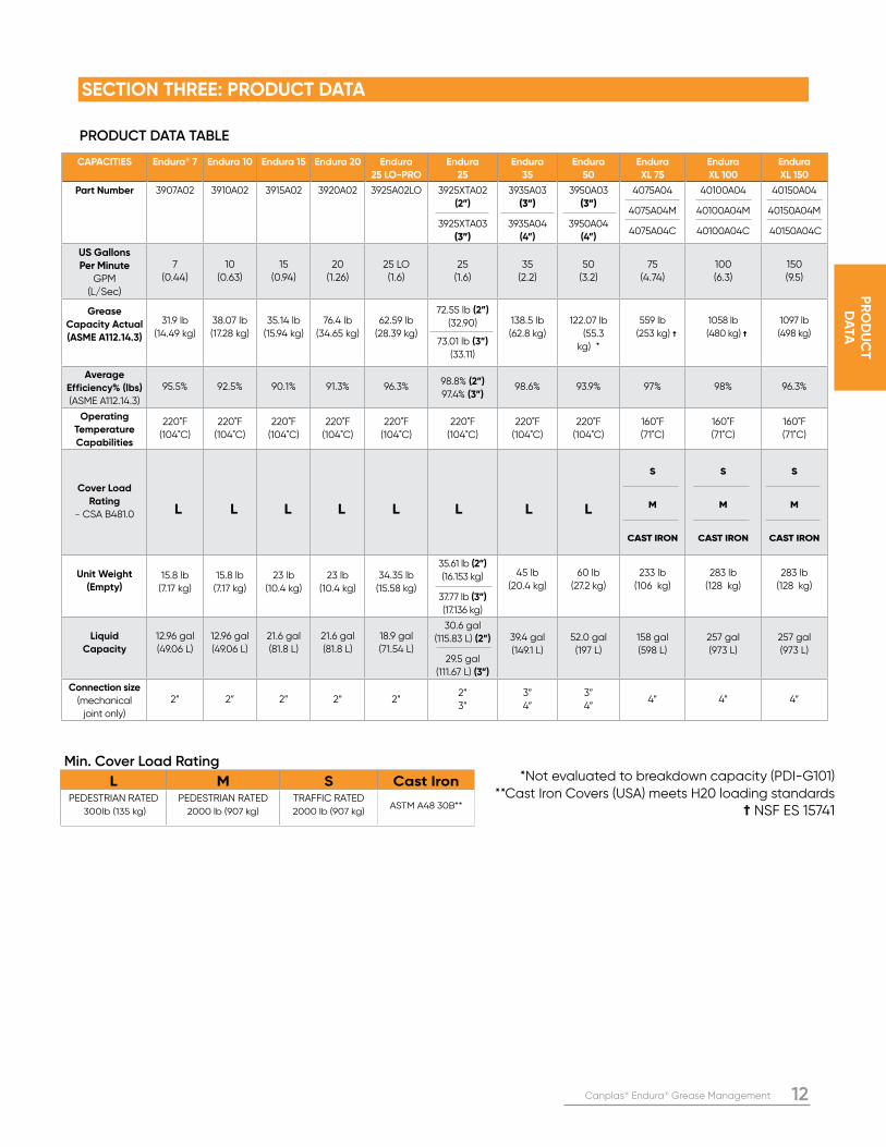
Min. Cover Load Rating
L M S Cast IronPEDESTRIAN RATED
300lb (135 kg)
PEDESTRIAN RATED
2000 lb (907 kg)
TRAFFIC RATED
2000 lb (907 kg)ASTM A48 30B**
*Not evaluated to breakdown capacity (PDI-G101)**Cast Iron Covers (USA) meets H20 loading standards
† NSF ES 15741
CAPACITIES Endura® 7 Endura 10 Endura 15 Endura 20 Endura
25 LO-PRO
Endura
25
Endura
35
Endura
50
Endura
XL 75
Endura
XL 100
Endura
XL 150
Part Number 3907A02 3910A02 3915A02 3920A02 3925A02LO 3925XTA02
(2”)
3925XTA03
(3”)
3935A03
(3”)
3935A04
(4”)
3950A03
(3”)
3950A04
(4”)
4075A04
4075A04M
4075A04C
40100A04
40100A04M
40100A04C
40150A04
40150A04M
40150A04C
US Gallons Per Minute
GPM (L/Sec)
7 (0.44)
10 (0.63)
15 (0.94)
20 (1.26)
25 LO (1.6)
25 (1.6)
35 (2.2)
50 (3.2)
75 (4.74)
100 (6.3)
150 (9.5)
Grease
Capacity Actual
(ASME A112.14.3)
31.9 lb
(14.49 kg)
38.07 lb
(17.28 kg)
35.14 lb
(15.94 kg)
76.4 lb
(34.65 kg)
62.59 lb
(28.39 kg)
72.55 lb (2”)
(32.90)
73.01 lb (3”)
(33.11)
138.5 lb
(62.8 kg)
122.07 lb
(55.3
kg) *
559 lb
(253 kg) †
1058 lb
(480 kg) †
1097 lb
(498 kg)
Average
Efficiency% (lbs)
(ASME A112.14.3)
95.5% 92.5% 90.1% 91.3% 96.3%98.8% (2”)
97.4% (3”)98.6% 93.9% 97% 98% 96.3%
Operating
Temperature
Capabilities
220˚F
(104˚C)
220˚F
(104˚C)
220˚F
(104˚C)
220˚F
(104˚C)
220˚F
(104˚C)
220˚F
(104˚C)
220˚F
(104˚C)
220˚F
(104˚C)
160˚F
(71˚C)
160˚F
(71˚C)
160˚F
(71˚C)
Cover Load
Rating
- CSA B481.0 L L L L L L L L
S
M
CAST IRON
S
M
CAST IRON
S
M
CAST IRON
Unit Weight
(Empty) 15.8 lb
(7.17 kg)
15.8 lb
(7.17 kg)
23 lb
(10.4 kg)
23 lb
(10.4 kg)
34.35 lb
(15.58 kg)
35.61 lb (2”)
(16.153 kg)
37.77 lb (3”)
(17.136 kg)
45 lb
(20.4 kg)
60 lb
(27.2 kg)
233 lb
(106 kg)
283 lb
(128 kg)
283 lb
(128 kg)
Liquid
Capacity
12.96 gal
(49.06 L)
12.96 gal
(49.06 L)
21.6 gal
(81.8 L)
21.6 gal
(81.8 L)
18.9 gal
(71.54 L)
30.6 gal
(115.83 L) (2”)
29.5 gal
(111.67 L) (3”)
39.4 gal
(149.1 L)
52.0 gal
(197 L)
158 gal
(598 L)
257 gal
(973 L)
257 gal
(973 L)
Connection size
(mechanical
joint only)
2” 2” 2” 2” 2”2”
3”
3”
4”
3”
4”4” 4” 4”
SECTION THREE: PRODUCT DATA
PRODUCT DATA TABLE
13 Canplas® Endura® Grease Management
PR
OD
UC
T
DA
TA
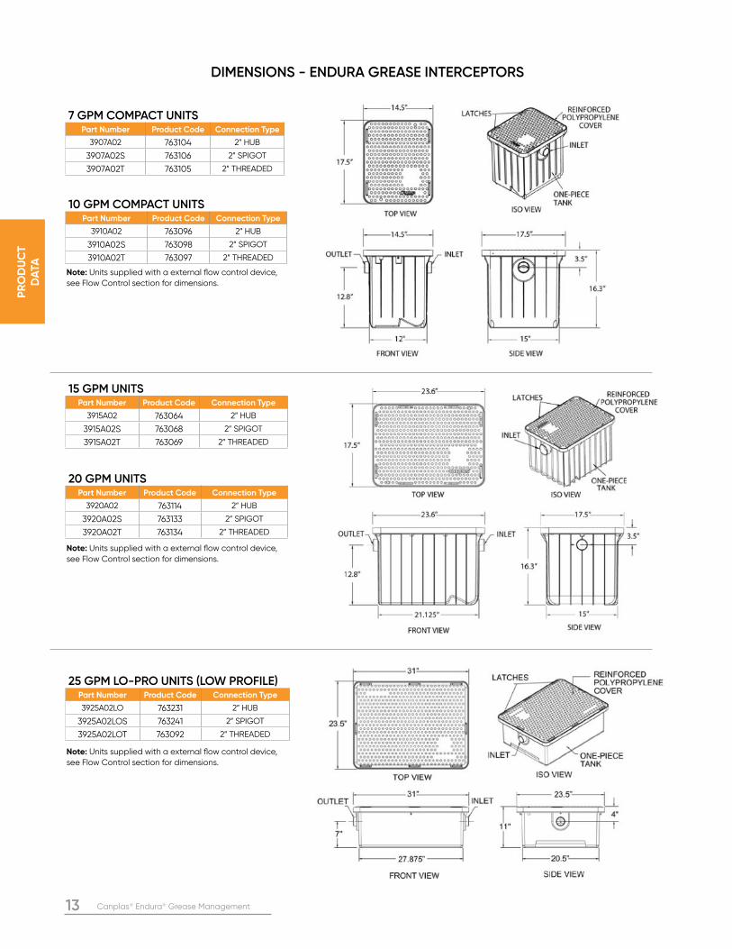
7 GPM COMPACT UNITSPart Number Product Code Connection Type
3907A02 763104 2” HUB
3907A02S 763106 2” SPIGOT
3907A02T 763105 2” THREADED
10 GPM COMPACT UNITSPart Number Product Code Connection Type
3910A02 763096 2” HUB
3910A02S 763098 2” SPIGOT
3910A02T 763097 2” THREADED
15 GPM UNITSPart Number Product Code Connection Type
3915A02 763064 2” HUB
3915A02S 763068 2” SPIGOT
3915A02T 763069 2” THREADED
20 GPM UNITSPart Number Product Code Connection Type
3920A02 763114 2” HUB
3920A02S 763133 2” SPIGOT
3920A02T 763134 2” THREADED
25 GPM LO-PRO UNITS (LOW PROFILE)Part Number Product Code Connection Type
3925A02LO 763231 2” HUB
3925A02LOS 763241 2” SPIGOT
3925A02LOT 763092 2” THREADED
Note: Units supplied with a external flow control device,
see Flow Control section for dimensions.
Note: Units supplied with a external flow control device,
see Flow Control section for dimensions.
Note: Units supplied with a external flow control device,
see Flow Control section for dimensions.
DIMENSIONS - ENDURA GREASE INTERCEPTORS
Canplas® Endura® Grease Management 14
PR
OD
UC
T
DA
TA
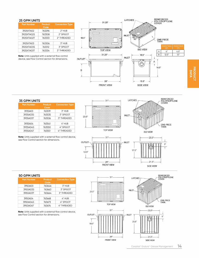
A
B
3925XTA02 (2”)
3925XTA03 (3”)
A 4” 4.5”
B 12.5” 12”
25 GPM UNITSPart Number Product
Code
Connection Type
3925XTA02 763296 2” HUB
3925XTA02S 763308 2” SPIGOT
3925XTA02T 763333 2” THREADED
35 GPM UNITSPart Number Product
Code
Connection Type
3935A03 763519 3” HUB
3935A03S 763535 3” SPIGOT
3935A03T 763536 3” THREADED
50 GPM UNITSPart Number Product
Code
Connection Type
3950A03 763646 3” HUB
3950A03S 763663 3” SPIGOT
3950A03T 763664 3” THREADED
3925XTA03 763306 3” HUB
3925XTA03S 763312 3” SPIGOT
3925XTA03T 763334 3” THREADED
3935A04 763541 4” HUB
3935A04S 763550 4” SPIGOT
3935A04T 763551 4” THREADED
3950A04 763668 4” HUB
3950A04S 763673 4” SPIGOT
3950A04T 763674 4” THREADED
Note: Units supplied with a external flow control
device, see Flow Control section for dimensions.
Note: Units supplied with a external flow control device,
see Flow Control section for dimensions.
Note: Units supplied with a external flow control device,
see Flow Control section for dimensions.
15 Canplas® Endura® Grease Management
PR
OD
UC
T
DA
TA
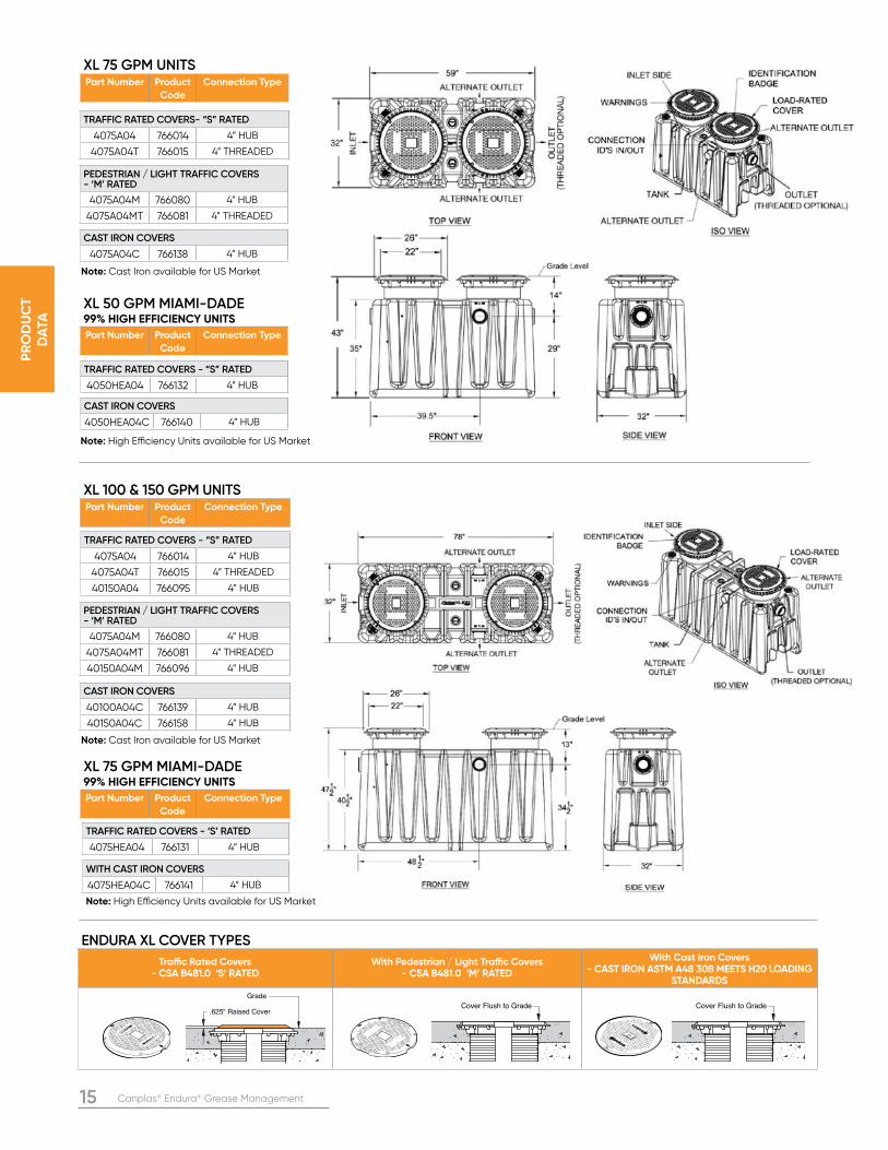
TRAFFIC RATED COVERS- “S” RATED
4075A04 766014 4” HUB
4075A04T 766015 4” THREADED
TRAFFIC RATED COVERS - “S” RATED
4075A04 766014 4” HUB
4075A04T 766015 4” THREADED
40150A04 766095 4” HUB
XL 75 GPM UNITS Part Number Product
Code
Connection Type
XL 50 GPM MIAMI-DADE 99% HIGH EFFICIENCY UNITS Part Number Product
Code
Connection Type
XL 75 GPM MIAMI-DADE 99% HIGH EFFICIENCY UNITS Part Number Product
Code
Connection Type
XL 100 & 150 GPM UNITS Part Number Product
Code
Connection Type
PEDESTRIAN / LIGHT TRAFFIC COVERS - ‘M’ RATED
4075A04M 766080 4” HUB
4075A04MT 766081 4” THREADED
PEDESTRIAN / LIGHT TRAFFIC COVERS - ‘M’ RATED
4075A04M 766080 4” HUB
4075A04MT 766081 4” THREADED
40150A04M 766096 4” HUB
CAST IRON COVERS
4075A04C 766138 4” HUB
CAST IRON COVERS
40100A04C 766139 4” HUB
40150A04C 766158 4” HUB
ENDURA XL COVER TYPES
Traffic Rated Covers - CSA B481.0 ‘S’ RATED
With Pedestrian / Light Traffic Covers - CSA B481.0 ‘M’ RATED
With Cast Iron Covers - CAST IRON ASTM A48 30B MEETS H20 LOADING
STANDARDS
GREASE INTERCEPTOR
GREASE INTERCEPTOR
Note: Cast Iron available for US Market
Note: Cast Iron available for US Market
TRAFFIC RATED COVERS - “S” RATED
4050HEA04 766132 4” HUB
CAST IRON COVERS
4050HEA04C 766140 4” HUB
Note: High Efficiency Units available for US Market
Note: High Efficiency Units available for US Market
TRAFFIC RATED COVERS - ‘S’ RATED
4075HEA04 766131 4” HUB
WITH CAST IRON COVERS
4075HEA04C 766141 4” HUB
Grade
.625" Raised CoverCover Flush to Grade Cover Flush to Grade
Canplas® Endura® Grease Management 16
PR
OD
UC
T
DA
TA
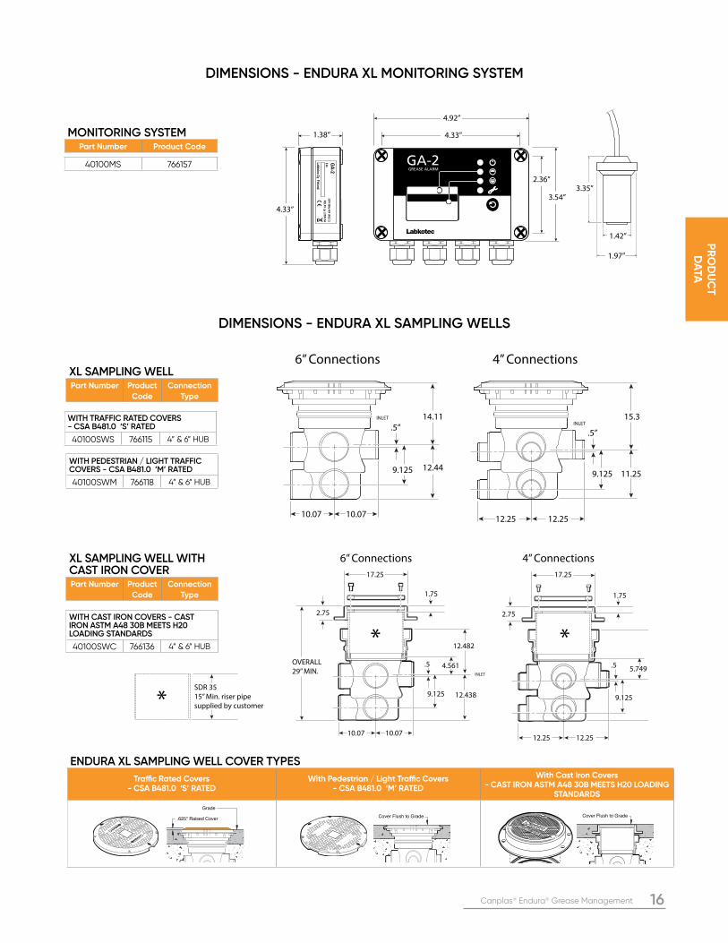
WITH TRAFFIC RATED COVERS - CSA B481.0 ‘S’ RATED
40100SWS 766115 4” & 6” HUB
XL SAMPLING WELL Part Number Product
Code
Connection
Type
XL SAMPLING WELL WITH CAST IRON COVER Part Number Product
Code
Connection
Type
WITH PEDESTRIAN / LIGHT TRAFFIC COVERS - CSA B481.0 ‘M’ RATED
40100SWM 766118 4” & 6” HUB
WITH CAST IRON COVERS - CAST IRON ASTM A48 30B MEETS H20 LOADING STANDARDS
40100SWC 766136 4” & 6” HUB
INLET15.3
11.259.125
12.25 12.25
INLET 14.11
.5”
4” Connections6” Connections
.5”
12.449.125
10.07 10.07
SDR 35
15” Min. riser pipe
supplied by customer*
12.482
13.67
11.25
.5
4” Connections
* *
6” Connections
INLET
.5 4.561 5.749
12.438
OVERALL
29” MIN.
9.1259.125
17.25 17.25
1.75 1.75
2.752.75
10.07 10.0712.2512.25
DIMENSIONS - ENDURA XL SAMPLING WELLS
DIMENSIONS - ENDURA XL MONITORING SYSTEM
40100MS 766157
MONITORING SYSTEMPart Number Product Code
4.33”
4.92”
4.33”1.38”
3.54”
2.36”3.35”
1.97”
1.42”
ENDURA XL SAMPLING WELL COVER TYPES
Traffic Rated Covers - CSA B481.0 ‘S’ RATED
With Pedestrian / Light Traffic Covers - CSA B481.0 ‘M’ RATED
With Cast Iron Covers - CAST IRON ASTM A48 30B MEETS H20 LOADING
STANDARDS
GREASE INTERCEPTOR
GREASE INTERCEPTOR
Grade
.625" Raised CoverCover Flush to Grade Cover Flush to Grade

17 Canplas® Endura® Grease Management
PR
OD
UC
T
DA
TA
DIMENSIONS - SOLIDS INTERCEPTOR AND SOLIDS BASKET ACCESSORY (SBA)
NOTE: Endura® XL models are supplied as standard with an internal
flow control excluding Endura XL HE models for Miami Dade
DERM 2.0. 4” External flow controls are available separately.
1 Piece Compact Flow Control - Standard on 7, 10,15, 20, 2” 25 GPM UNITS
Note: For Installations that require sleeve extension for
FCD, 2 piece 2” FCD is required.
2 Piece Flow Control - Standard on 3” 25, 35, AND 50 GPM UNITS,
Dim. 2” spg x h
3” spg x h
4” spg x h
XL Models4” h x h
A 6.67” 8.4” min. 17.24”
min. 17.24”
B 0.27” 0.38” 0.45” 0.45”
C 1.56” 1.74” 2.1” 2.1”
DAir Intake pipe size
2” 2” 2” 2”
Dim. 2” h x h
A 3.94”
B 3.44” A
B
A
CD
B
DIMENSIONS - FLOW CONTROL DEVICE ASSEMBLY
3911A02 763096 25 GPM 3911A03 763467 60 GPM
4011A04 766163 125 GPM 3911A-1 763126 N/A
2” HUB SOLIDS INTERCEPTOR Part Number Product Code Max Flow Rate
3” HUB SOLIDS INTERCEPTOR Part Number Product Code Max Flow Rate
4” HUB SOLIDS INTERCEPTOR Part Number Product Code Max Flow Rate
SOLIDS BASKET ACCESSORY Part Number Product Code Connection Type
Note: Units supplied with internal Solids Basket Accessory Note: Units supplied with internal Solids Basket Accessory
Note: Units supplied with internal Solids Basket Accessory
7.25”
” 13.875”
5” 3”
11.375”
14.375”
Canplas® Endura® Grease Management 18
INS
TALLA
TIO
N
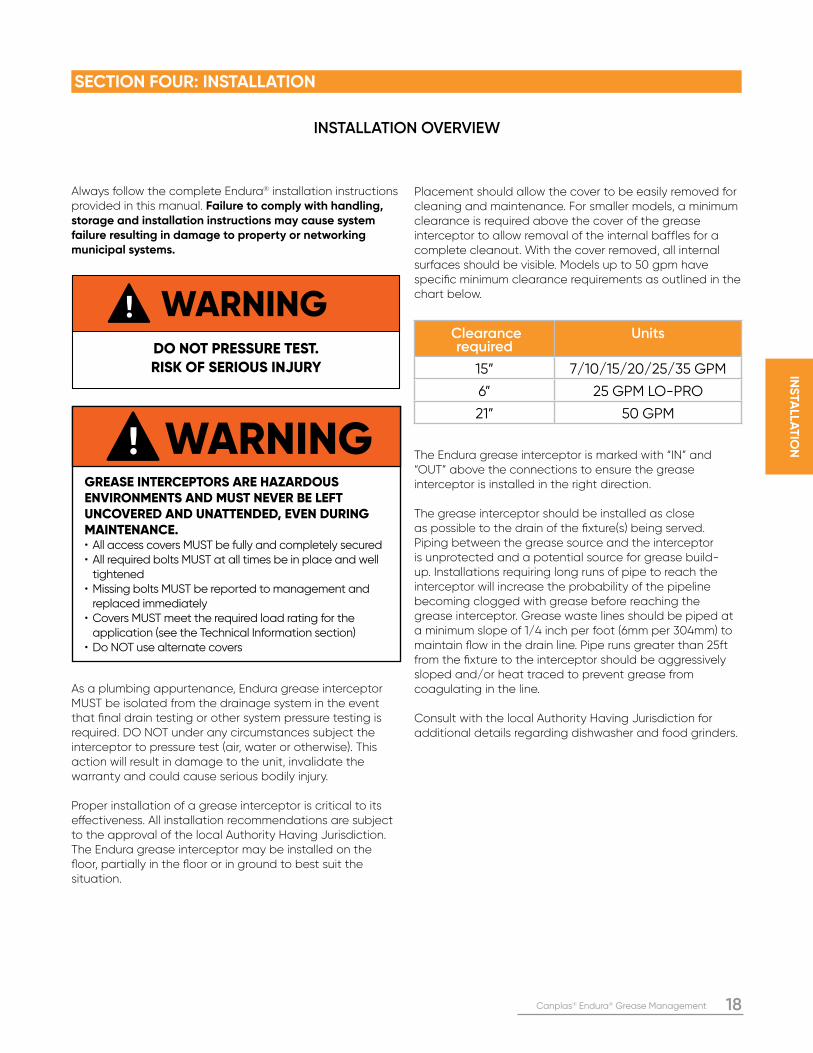
Always follow the complete Endura® installation instructions provided in this manual. Failure to comply with handling, storage and installation instructions may cause system failure resulting in damage to property or networking municipal systems.
As a plumbing appurtenance, Endura grease interceptor MUST be isolated from the drainage system in the event that final drain testing or other system pressure testing is required. DO NOT under any circumstances subject the interceptor to pressure test (air, water or otherwise). This action will result in damage to the unit, invalidate the warranty and could cause serious bodily injury.
Proper installation of a grease interceptor is critical to its effectiveness. All installation recommendations are subject to the approval of the local Authority Having Jurisdiction. The Endura grease interceptor may be installed on the floor, partially in the floor or in ground to best suit the situation.
Placement should allow the cover to be easily removed for cleaning and maintenance. For smaller models, a minimum clearance is required above the cover of the grease interceptor to allow removal of the internal baffles for a complete cleanout. With the cover removed, all internal surfaces should be visible. Models up to 50 gpm have specific minimum clearance requirements as outlined in the chart below.
The Endura grease interceptor is marked with “IN” and “OUT” above the connections to ensure the grease interceptor is installed in the right direction.
The grease interceptor should be installed as close as possible to the drain of the fixture(s) being served. Piping between the grease source and the interceptor is unprotected and a potential source for grease build-up. Installations requiring long runs of pipe to reach the interceptor will increase the probability of the pipeline becoming clogged with grease before reaching the grease interceptor. Grease waste lines should be piped at a minimum slope of 1/4 inch per foot (6mm per 304mm) to maintain flow in the drain line. Pipe runs greater than 25ft from the fixture to the interceptor should be aggressively sloped and/or heat traced to prevent grease from coagulating in the line.
Consult with the local Authority Having Jurisdiction for additional details regarding dishwasher and food grinders.
WARNINGDO NOT PRESSURE TEST. RISK OF SERIOUS INJURY
Clearance required
Units
15” 7/10/15/20/25/35 GPM
6” 25 GPM LO-PRO
21” 50 GPM
INSTALLATION OVERVIEW
SECTION FOUR: INSTALLATION
WARNINGGREASE INTERCEPTORS ARE HAZARDOUS ENVIRONMENTS AND MUST NEVER BE LEFT UNCOVERED AND UNATTENDED, EVEN DURING MAINTENANCE. • All access covers MUST be fully and completely secured• All required bolts MUST at all times be in place and well tightened• Missing bolts MUST be reported to management and replaced immediately• Covers MUST meet the required load rating for the application (see the Technical Information section)• Do NOT use alternate covers
19 Canplas® Endura® Grease Management
INS
TALL
AT
ION
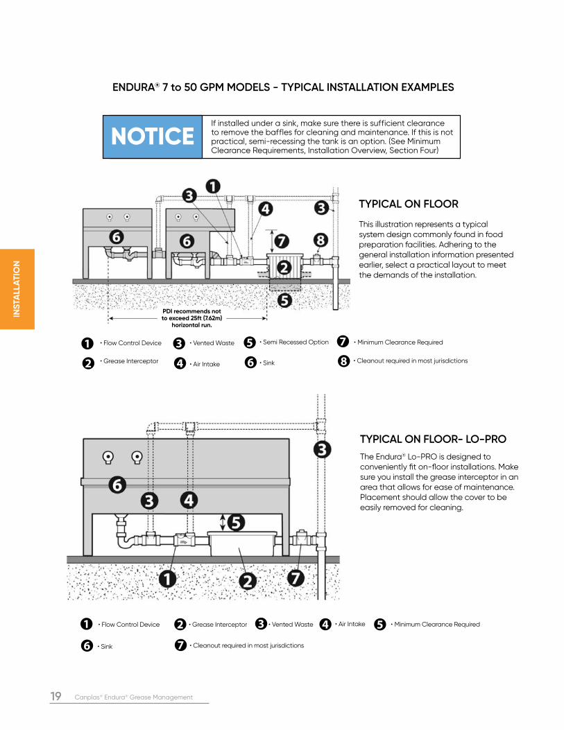
TYPICAL ON FLOOR
This illustration represents a typical system design commonly found in food preparation facilities. Adhering to the general installation information presented earlier, select a practical layout to meet the demands of the installation.
PDI recommends not to exceed 25ft (7.62m)
horizontal run.
• Flow Control Device • Vented Waste • Semi Recessed Option • Minimum Clearance Required
• Grease Interceptor • Air Intake • Sink • Cleanout required in most jurisdictions
ENDURA® 7 to 50 GPM MODELS - TYPICAL INSTALLATION EXAMPLES
TYPICAL ON FLOOR- LO-PRO
The Endura® Lo-PRO is designed to conveniently fit on-floor installations. Make sure you install the grease interceptor in an area that allows for ease of maintenance. Placement should allow the cover to be easily removed for cleaning.
• Flow Control Device • Vented Waste • Minimum Clearance Required • Grease Interceptor • Air Intake
• Sink • Cleanout required in most jurisdictions
NOTICEIf installed under a sink, make sure there is sufficient clearance to remove the baffles for cleaning and maintenance. If this is not practical, semi-recessing the tank is an option. (See Minimum Clearance Requirements, Installation Overview, Section Four)
Canplas® Endura® Grease Management 20
INS
TALLA
TIO
N
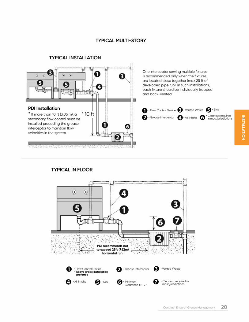
PDI recommends not to exceed 25ft (7.62m)
horizontal run.
TYPICAL IN FLOOR
• Flow Control Device* Above grade installation preferred
• Vented Waste
• Minimum Clearance 15”-21”
• Grease Interceptor
• Air Intake • Sink • Cleanout required in most jurisdictions
TYPICAL MULTI-STORY
TYPICAL INSTALLATION
• Cleanout required in most jurisdictions
• Flow Control Device • Vented Waste
• Grease Interceptor • Air Intake
• SinkPDI Installation
* If more than 10 ft (3.05 m), a secondary flow control must be installed preceding the grease interceptor to maintain flow velocities in the system.
* 10 ft
One interceptor serving multiple fixtures is recommended only when the fixtures are located close together (max 25 ft of developed pipe run). In such installations, each fixture should be individually trapped and back-vented.
21 Canplas® Endura® Grease Management
INS
TALL
AT
ION
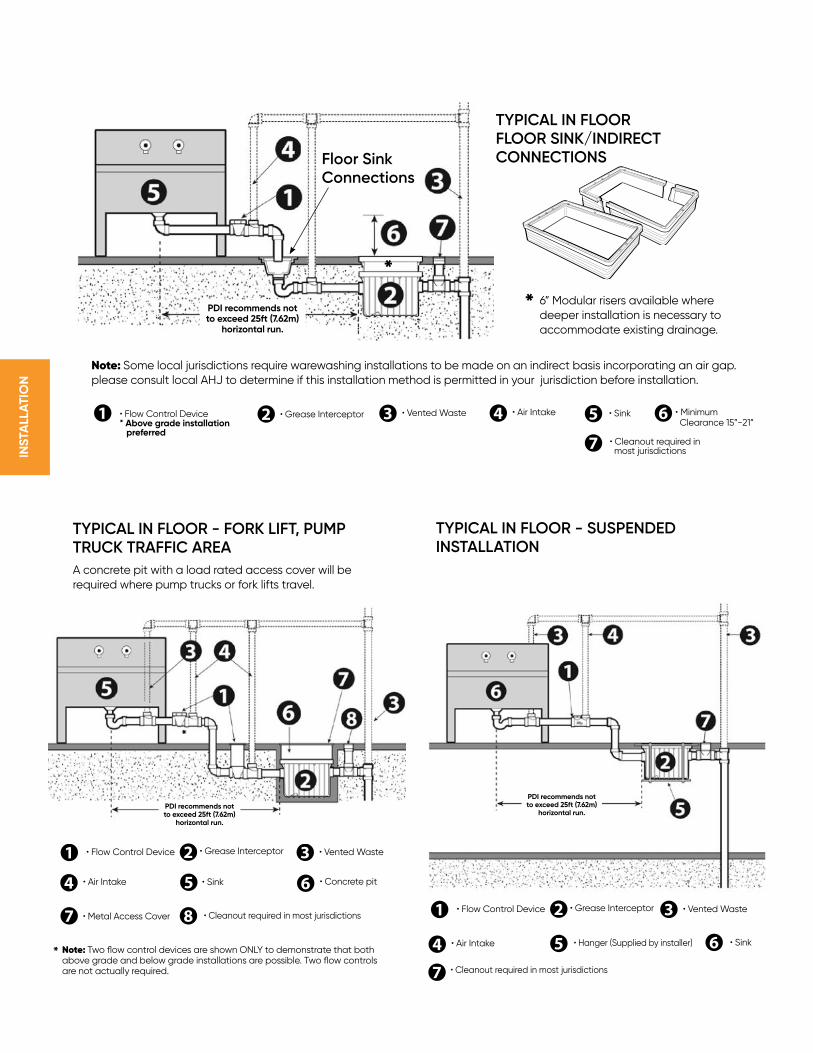
TYPICAL IN FLOOR - SUSPENDED INSTALLATION
TYPICAL IN FLOOR FLOOR SINK/INDIRECT CONNECTIONS
TYPICAL IN FLOOR - FORK LIFT, PUMP TRUCK TRAFFIC AREA
A concrete pit with a load rated access cover will be required where pump trucks or fork lifts travel.
PDI recommends not to exceed 25ft (7.62m)
horizontal run.
PDI recommends not to exceed 25ft (7.62m)
horizontal run.
• Hanger (Supplied by installer)
• Flow Control Device • Vented Waste• Grease Interceptor
• Air Intake
• Cleanout required in most jurisdictions
• SinkNote: Two flow control devices are shown ONLY to demonstrate that both above grade and below grade installations are possible. Two flow controls are not actually required.
• Metal Access Cover • Cleanout required in most jurisdictions
• Flow Control Device • Vented Waste• Grease Interceptor
• Air Intake • Concrete pit• Sink
*
*
Note: Some local jurisdictions require warewashing installations to be made on an indirect basis incorporating an air gap. please consult local AHJ to determine if this installation method is permitted in your jurisdiction before installation.
* 6” Modular risers available where deeper installation is necessary to accommodate existing drainage.
PDI recommends not to exceed 25ft (7.62m)
horizontal run.
*
Floor SinkConnections
• Flow Control Device* Above grade installation preferred
• Vented Waste • Minimum Clearance 15”-21”
• Grease Interceptor • Air Intake • Sink
• Cleanout required in most jurisdictions
Canplas® Endura® Grease Management 22
INS
TALLA
TIO
N
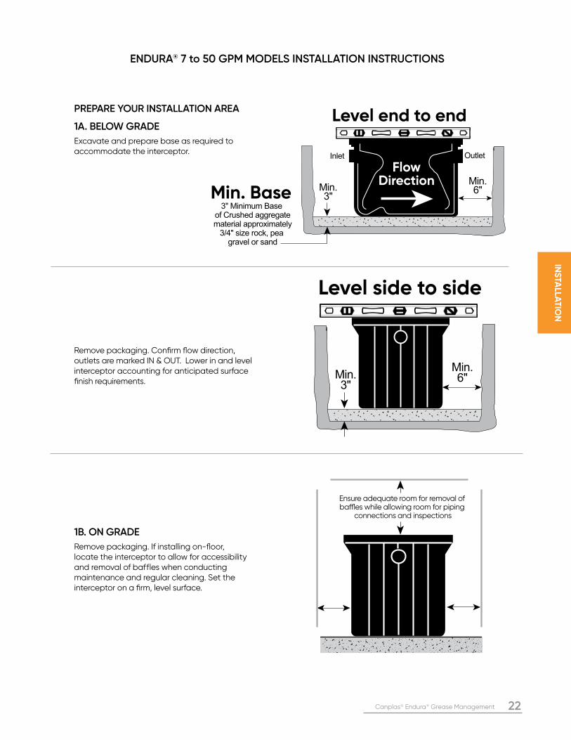
Ensure adequate room for removal of baffles while allowing room for piping
connections and inspections
Min.3"
Inlet Outlet
Min.6"
3" Minimum Base of Crushed aggregatematerial approximately
3/4" size rock, pea gravel or sand
Min. Base
Level end to end
Flow Direction
Min.3"
Min.6"
Level side to side
PREPARE YOUR INSTALLATION AREA 1A. BELOW GRADE
Excavate and prepare base as required to accommodate the interceptor.
Remove packaging. Confirm flow direction, outlets are marked IN & OUT. Lower in and level interceptor accounting for anticipated surface finish requirements.
1B. ON GRADE
Remove packaging. If installing on-floor, locate the interceptor to allow for accessibility and removal of baffles when conducting maintenance and regular cleaning. Set the interceptor on a firm, level surface.
ENDURA® 7 to 50 GPM MODELS INSTALLATION INSTRUCTIONS
23 Canplas® Endura® Grease Management
INS
TALL
AT
ION
Finished floor level
Finished floor level
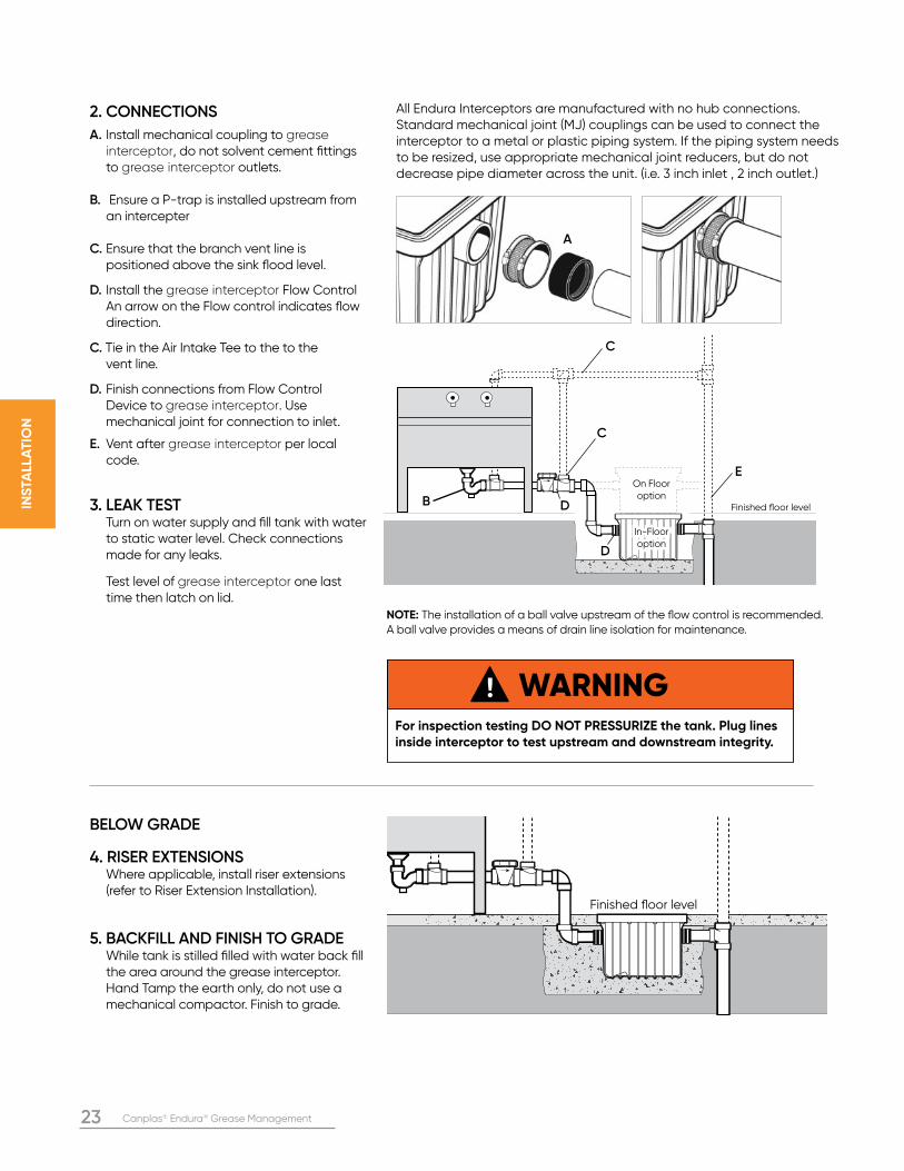
WARNINGFor inspection testing DO NOT PRESSURIZE the tank. Plug lines inside interceptor to test upstream and downstream integrity.
2. CONNECTIONS
A. Install mechanical coupling to grease interceptor, do not solvent cement fittings to grease interceptor outlets.
B. Ensure a P-trap is installed upstream from an intercepter
C. Ensure that the branch vent line is positioned above the sink flood level.
D. Install the grease interceptor Flow Control An arrow on the Flow control indicates flow direction.
C. Tie in the Air Intake Tee to the to the vent line.
D. Finish connections from Flow Control Device to grease interceptor. Use mechanical joint for connection to inlet.
E. Vent after grease interceptor per local code.
3. LEAK TEST Turn on water supply and fill tank with water to static water level. Check connections made for any leaks.
Test level of grease interceptor one last time then latch on lid.
BELOW GRADE
4. RISER EXTENSIONS Where applicable, install riser extensions (refer to Riser Extension Installation).
5. BACKFILL AND FINISH TO GRADE While tank is stilled filled with water back fill the area around the grease interceptor. Hand Tamp the earth only, do not use a mechanical compactor. Finish to grade.
On Floor option
In-Floor In-Floor optionoption
All Endura Interceptors are manufactured with no hub connections. Standard mechanical joint (MJ) couplings can be used to connect the interceptor to a metal or plastic piping system. If the piping system needs to be resized, use appropriate mechanical joint reducers, but do not decrease pipe diameter across the unit. (i.e. 3 inch inlet , 2 inch outlet.)
A
B D
C
D
C
E
NOTE: The installation of a ball valve upstream of the flow control is recommended. A ball valve provides a means of drain line isolation for maintenance.
Canplas® Endura® Grease Management 24
INS
TALLA
TIO
N
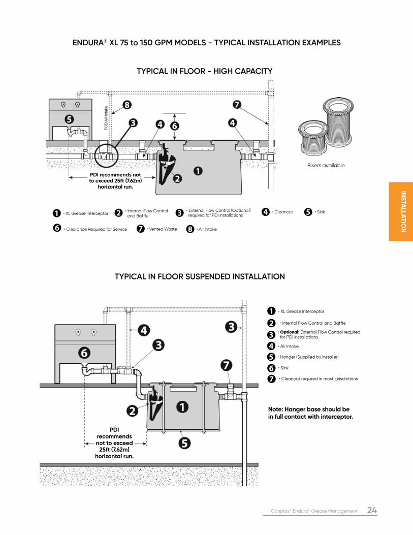
PDI recommends not to exceed 25ft (7.62m)
horizontal run.
TYPICAL IN FLOOR - HIGH CAPACITY
• XL Grease Interceptor• External Flow Control (Optional) required for PDI installations
• Vented Waste • Air Intake
• Internal Flow Control and Baffle
• Cleanout • Sink
• Clearance Required for Service
Risers available
ENDURA® XL 75 to 150 GPM MODELS - TYPICAL INSTALLATION EXAMPLES
TYPICAL IN FLOOR SUSPENDED INSTALLATION
Note: Hanger base should be in full contact with interceptor.
• Air Intake
• Sink
• Hanger (Supplied by installer)
• XL Grease Interceptor
• Optional: External Flow Control required for PDI installations
• Internal Flow Control and Baffle
• Cleanout required in most jurisdictions
PDI recommends not to exceed
25ft (7.62m) horizontal run.
25 Canplas® Endura® Grease Management
INS
TALL
AT
ION
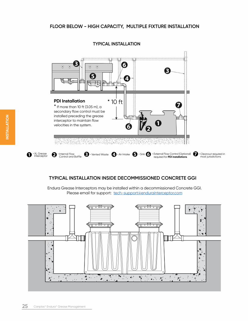
• XL Grease Interceptor
• External Flow Control (Optional) required for PDI installations
• Vented Waste• Internal Flow Control and Baffle
• Air Intake • Sink • Cleanout required in most jurisdictions
TYPICAL INSTALLATION
FLOOR BELOW - HIGH CAPACITY, MULTIPLE FIXTURE INSTALLATION
* 10 ftPDI Installation
* If more than 10 ft (3.05 m), a secondary flow control must be installed preceding the grease interceptor to maintain flow velocities in the system.
TYPICAL INSTALLATION INSIDE DECOMMISSIONED CONCRETE GGI
Endura Grease Interceptors may be installed within a decommissioned Concrete GGI. Please email for support: [email protected]
Canplas® Endura® Grease Management 26
INS
TALLA
TIO
N
Sampling well used as flow diverter
GREASE INTERCEPTOR
GREASE INTERCEPTOR
Sampling well used as flow diverter
GREASE INTERCEPTOR
GREASE INTERCEPTOR
Sampling well used as flow diverter
IN
GREASE INTERCEPTOR
GREASE INTERCEPTOR
Sampling well used as flow diverter
IN
GREASE INTERCEPTOR
GREASE INTERCEPTOR
C/OC/O
OUT
C/O C/O C/O
GREASE INTERCEPTOR
GREASE INTERCEPTOR
GREASE INTERCEPTOR
GREASE INTERCEPTOR
GREASE INTERCEPTOR
GREASE INTERCEPTOR
GREASE INTERCEPTOR
GREASE INTERCEPTOR
IN
OUT
C/O
C/O
C/O
C/O
GREASE INTERCEPTOR
GREASE INTERCEPTOR
GREASE INTERCEPTOR
GREASE INTERCEPTOR
GREASE INTERCEPTOR
GREASE INTERCEPTOR
C/O C/O C/O
GREASE INTERCEPTOR
GREASE INTERCEPTOR
GREASE INTERCEPTOR
GREASE INTERCEPTOR
GREASE INTERCEPTOR
GREASE INTERCEPTOR
GREASE INTERCEPTOR
GREASE INTERCEPTOR
Sampling well used as flow diverter
C/OC/O
C/O
C/OC/O
C/OC/O
GREASE INTERCEPTOR
GREASE INTERCEPTOR
GREASE INTERCEPTOR
GREASE INTERCEPTOR
GREASE INTERCEPTOR
GREASE INTERCEPTOR
GREASE INTERCEPTOR
GREASE INTERCEPTOR
GREASE INTERCEPTOR
GREASE INTERCEPTOR
GREASE INTERCEPTOR
GREASE INTERCEPTOR
GREASE INTERCEPTOR
GREASE INTERCEPTOR
GREASE INTERCEPTOR
GREASE INTERCEPTOR
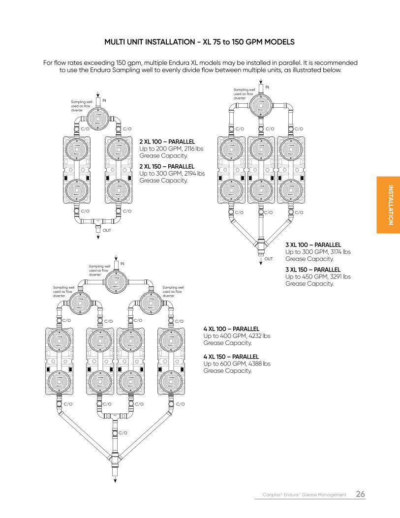
2 XL 100 – PARALLELUp to 200 GPM, 2116 lbs Grease Capacity.
2 XL 150 – PARALLELUp to 300 GPM, 2194 lbs Grease Capacity.
3 XL 100 – PARALLEL Up to 300 GPM, 3174 lbs Grease Capacity.
3 XL 150 – PARALLEL Up to 450 GPM, 3291 lbs Grease Capacity.
4 XL 100 – PARALLELUp to 400 GPM, 4232 lbs Grease Capacity.
4 XL 150 – PARALLELUp to 600 GPM, 4388 lbs Grease Capacity.
MULTI UNIT INSTALLATION - XL 75 to 150 GPM MODELS
For flow rates exceeding 150 gpm, multiple Endura XL models may be installed in parallel. It is recommended to use the Endura Sampling well to evenly divide flow between multiple units, as illustrated below.
27 Canplas® Endura® Grease Management
INS
TALL
AT
ION
OUT
OUTOUT
OUTIN
IN IN
C/OC/O
C/O C/O C/O
GR
EA
SE
IN
TE
RC
EP
TO
RGR
EA
SE
INT
ER
CE
PT
ORG
RE
AS
E I
NT
ER
CE
PT
ORG
RE
AS
E IN
TE
RC
EP
TO
R
OUT
C/OC/O
IN
GR
EA
SE
IN
TE
RC
EP
TO
RGR
EA
SE
INT
ER
CE
PT
ORG
RE
AS
E I
NT
ER
CE
PT
ORG
RE
AS
E IN
TE
RC
EP
TO
R
C/O
OUT
C/OC/O
IN
C/O
GR
EA
SE
IN
TE
RC
EP
TO
RGR
EA
SE
INT
ER
CE
PT
ORG
RE
AS
E I
NT
ER
CE
PT
ORG
RE
AS
E IN
TE
RC
EP
TO
R GR
EA
SE
IN
TE
RC
EP
TO
RGR
EA
SE
INT
ER
CE
PT
ORG
RE
AS
E I
NT
ER
CE
PT
ORG
RE
AS
E IN
TE
RC
EP
TO
R
C/OC/O
IN
C/O
OUT
C/O
GR
EA
SE
IN
TE
RC
EP
TO
RGR
EA
SE
INT
ER
CE
PT
ORG
RE
AS
E I
NT
ER
CE
PT
ORG
RE
AS
E IN
TE
RC
EP
TO
R
GREASE INTERCEPTOR
GREASE INTERCEPTOR
GREASE INTERCEPTOR
GREASE INTERCEPTOR GREASE INTERCEPTOR
GREASE INTERCEPTOR
GREASE INTERCEPTOR
GREASE INTERCEPTOR GREASE INTERCEPTOR
GREASE INTERCEPTOR
GREASE INTERCEPTOR
GREASE INTERCEPTOR GREASE INTERCEPTOR
GREASE INTERCEPTOR
GREASE INTERCEPTOR
GREASE INTERCEPTOR
GR
EA
SE
IN
TE
RC
EP
TO
RGR
EA
SE
INT
ER
CE
PT
ORG
RE
AS
E I
NT
ER
CE
PT
ORG
RE
AS
E IN
TE
RC
EP
TO
R GR
EA
SE
IN
TE
RC
EP
TO
RGR
EA
SE
INT
ER
CE
PT
ORG
RE
AS
E I
NT
ER
CE
PT
ORG
RE
AS
E IN
TE
RC
EP
TO
R
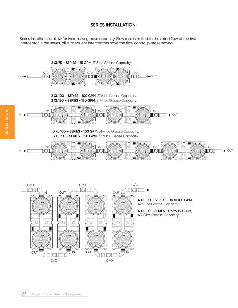
2 XL 75 – SERIES - 75 GPM, 1118 lbs Grease Capacity.
2 XL 100 – SERIES - 100 GPM, 2116 lbs Grease Capacity.
2 XL 150 – SERIES - 150 GPM, 2194 lbs Grease Capacity.
3 XL 100 – SERIES - 100 GPM, 3174 lbs Grease Capacity.
3 XL 150 – SERIES - 150 GPM, 3291 lbs Grease Capacity.
4 XL 100 – SERIES - Up to 100 GPM, 4232 lbs Grease Capacity.
4 XL 150 – SERIES - Up to 150 GPM, 4388 lbs Grease Capacity.
SERIES INSTALLATION:
Series installations allow for increased grease capacity. Flow rate is limited to the rated flow of the first interceptor in the series, all subsequent interceptors have the flow control plate removed.
Canplas® Endura® Grease Management 28
INS
TALLA
TIO
N
Ensure adequate room for piping connections
and inspections
Min.6"
Inlet Outlet
Min.12"
6" Minimum Base of Crushed aggregatematerial approximately
3/4" size rock, pea gravel or sand
Base
Level end to end
Flow Direction
Concrete Anchor Base (if anchoring
is required)
Min.12"
Min.8"
Level side to side
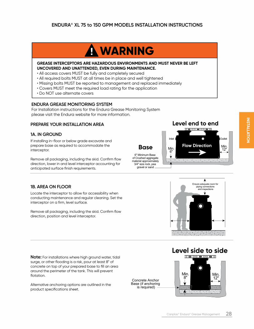
PREPARE YOUR INSTALLATION AREA 1A. IN GROUND
If installing in-floor or below grade excavate and prepare base as required to accommodate the interceptor.
Remove all packaging, including the skid. Confirm flow direction, lower in and level interceptor accounting for anticipated surface finish requirements.
1B. AREA ON FLOOR
Locate the interceptor to allow for accessibility when conducting maintenance and regular cleaning. Set the interceptor on a firm, level surface.
Remove all packaging, including the skid. Confirm flow direction, position and level interceptor.
Note: For installations where high ground water, tidal surge, or other flooding is a risk, pour at least 8” of concrete on top of your prepared base to fill an area around the perimeter of the tank. This will prevent flotation.
Alternative anchoring options are outlined in the product specifications sheet.
ENDURA® XL 75 to 150 GPM MODELS INSTALLATION INSTRUCTIONS
ENDURA GREASE MONITORING SYSTEM For Installation instructions for the Endura Grease Monitoring System please visit the Endura website for more information.
WARNINGGREASE INTERCEPTORS ARE HAZARDOUS ENVIRONMENTS AND MUST NEVER BE LEFT UNCOVERED AND UNATTENDED, EVEN DURING MAINTENANCE.• All access covers MUST be fully and completely secured• All required bolts MUST at all times be in place and well tightened• Missing bolts MUST be reported to management and replaced immediately• Covers MUST meet the required load rating for the application• Do NOT use alternate covers
29 Canplas® Endura® Grease Management
INS
TALL
AT
ION
GR
EA
SE
IN
TE
RC
EP
TO
RGR
EA
SE
INT
ER
CE
PT
ORG
RE
AS
E I
NT
ER
CE
PT
ORG
RE
AS
E IN
TE
RC
EP
TO
R
OUTSIDE -
SIDE - OUT
END - OUTIN
Max. 25ft(for PDI)
PDI External Flow Control installation
CleanoutCleanoutFC
D A
ir Inta
ke
Sink
Inlet Outlet
Fill with water to static level
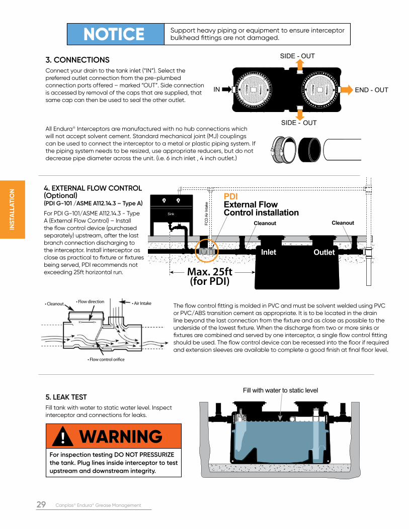
NOTICE Support heavy piping or equipment to ensure interceptor bulkhead fittings are not damaged.
WARNINGFor inspection testing DO NOT PRESSURIZE
the tank. Plug lines inside interceptor to test
upstream and downstream integrity.
3. CONNECTIONSConnect your drain to the tank inlet (“IN”). Select the preferred outlet connection from the pre-plumbed connection ports offered – marked “OUT”. Side connection is accessed by removal of the caps that are supplied, that same cap can then be used to seal the other outlet.
4. EXTERNAL FLOW CONTROL (Optional)(PDI G-101 /ASME A112.14.3 – Type A)
For PDI G-101/ASME A112.14.3 - Type A (External Flow Control) – Install the flow control device (purchased separately) upstream, after the last branch connection discharging to the interceptor. Install interceptor as close as practical to fixture or fixtures being served, PDI recommends not exceeding 25ft horizontal run.
The flow control fitting is molded in PVC and must be solvent welded using PVC or PVC/ABS transition cement as appropriate. It is to be located in the drain line beyond the last connection from the fixture and as close as possible to the underside of the lowest fixture. When the discharge from two or more sinks or fixtures are combined and served by one interceptor, a single flow control fitting should be used. The flow control device can be recessed into the floor if required and extension sleeves are available to complete a good finish at final floor level.
5. LEAK TEST
Fill tank with water to static water level. Inspect interceptor and connections for leaks.
All Endura® Interceptors are manufactured with no hub connections which will not accept solvent cement. Standard mechanical joint (MJ) couplings can be used to connect the interceptor to a metal or plastic piping system. If the piping system needs to be resized, use appropriate reducers, but do not decrease pipe diameter across the unit. (i.e. 6 inch inlet , 4 inch outlet.)
• Flow direction • Air Intake• Cleanout
• Flow control orifice
Canplas® Endura® Grease Management 30
INS
TALLA
TIO
N
Continue fill of
crushed aggregate
material, approximately
3/4" size rock,
pea gravel or sand
• Concrete Pad must extend min. 18” outside the unit footprint
• No.4 rebar (1/2”)
• 2-Way cleanout tee
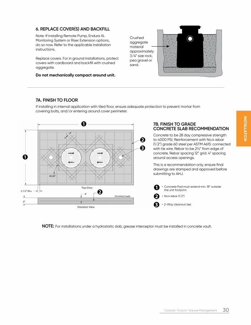
6. REPLACE COVER(S) AND BACKFILL
Note: If installing Remote Pump, Endura XL Monitoring System or Riser Extension options, do so now. Refer to the applicable installation instructions.
Replace covers. For in ground installations, protect covers with cardboard and backfill with crushed aggregate.
Do not mechanically compact around unit.
Crushed aggregate material approximately 3/4” size rock, pea gravel or sand.
7A. FINISH TO FLOOR
If installing in internal application with tiled floor, ensure adequate protection to prevent mortar from covering bolts, and/or entering around cover perimeter.
NOTE: For installations under a hydrostatic slab, grease interceptor must be installed in concrete vault.
7B. FINISH TO GRADECONCRETE SLAB RECOMMENDATION
Concrete to be 28 day compressive strength to 4000 PSI. Reinforcement with No.4 rebar (1/2”) grade 60 steel per ASTM A615: connected with tie wire. Rebar to be 2½” from edge of concrete. Rebar spacing 12” grid. 4” spacing around access openings. This is a recommendation only, ensure final drawings are stamped and approved before submitting to AHJ.
31 Canplas® Endura® Grease Management
INS
TALL
AT
ION
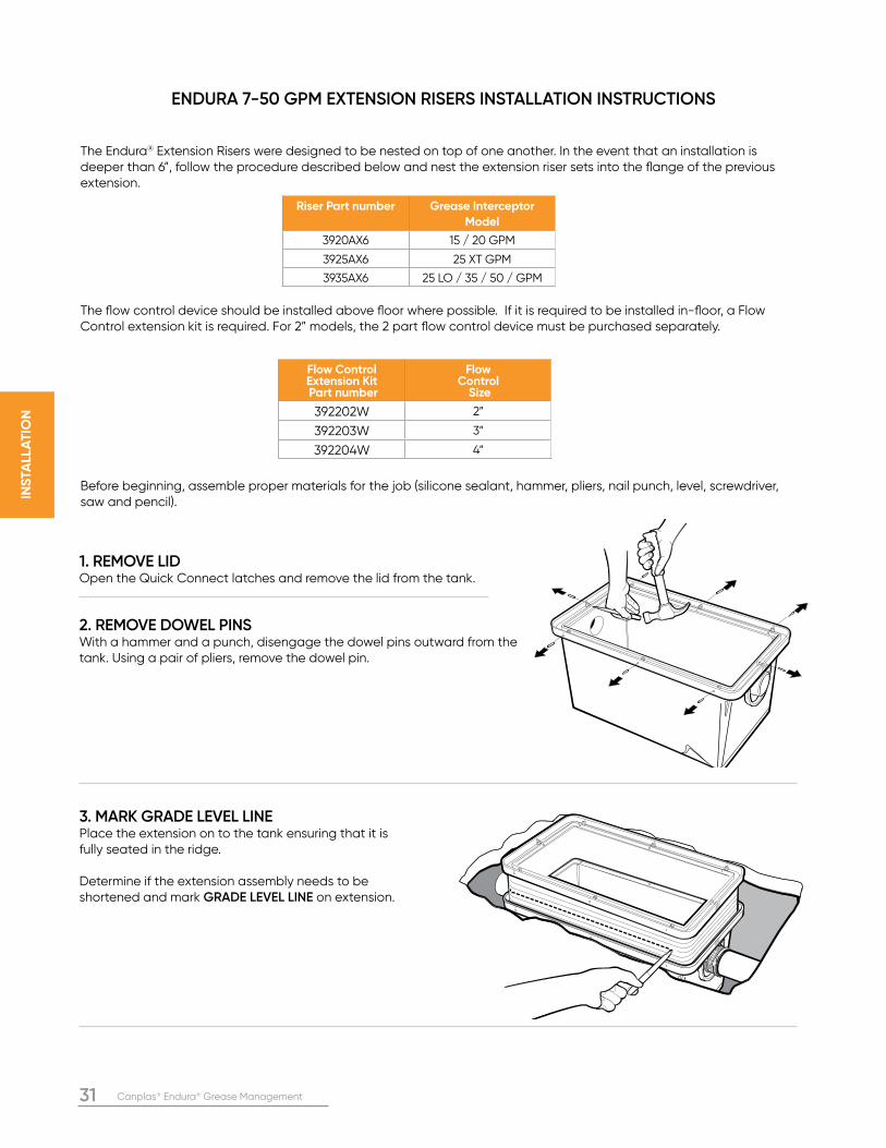
The Endura® Extension Risers were designed to be nested on top of one another. In the event that an installation is deeper than 6”, follow the procedure described below and nest the extension riser sets into the flange of the previous extension.
The flow control device should be installed above floor where possible. If it is required to be installed in-floor, a Flow Control extension kit is required. For 2” models, the 2 part flow control device must be purchased separately.
Before beginning, assemble proper materials for the job (silicone sealant, hammer, pliers, nail punch, level, screwdriver, saw and pencil).
1. REMOVE LIDOpen the Quick Connect latches and remove the lid from the tank.
2. REMOVE DOWEL PINSWith a hammer and a punch, disengage the dowel pins outward from the tank. Using a pair of pliers, remove the dowel pin.
3. MARK GRADE LEVEL LINEPlace the extension on to the tank ensuring that it is fully seated in the ridge.
Determine if the extension assembly needs to be shortened and mark GRADE LEVEL LINE on extension.
ENDURA 7-50 GPM EXTENSION RISERS INSTALLATION INSTRUCTIONS
Riser Part number Grease Interceptor
Model
3920AX6 15 / 20 GPM
3925AX6 25 XT GPM
3935AX6 25 LO / 35 / 50 / GPM
Flow Control Extension Kit Part number
Flow Control
Size
392202W 2”
392203W 3”
392204W 4”
Canplas® Endura® Grease Management 32
INS
TALLA
TIO
N
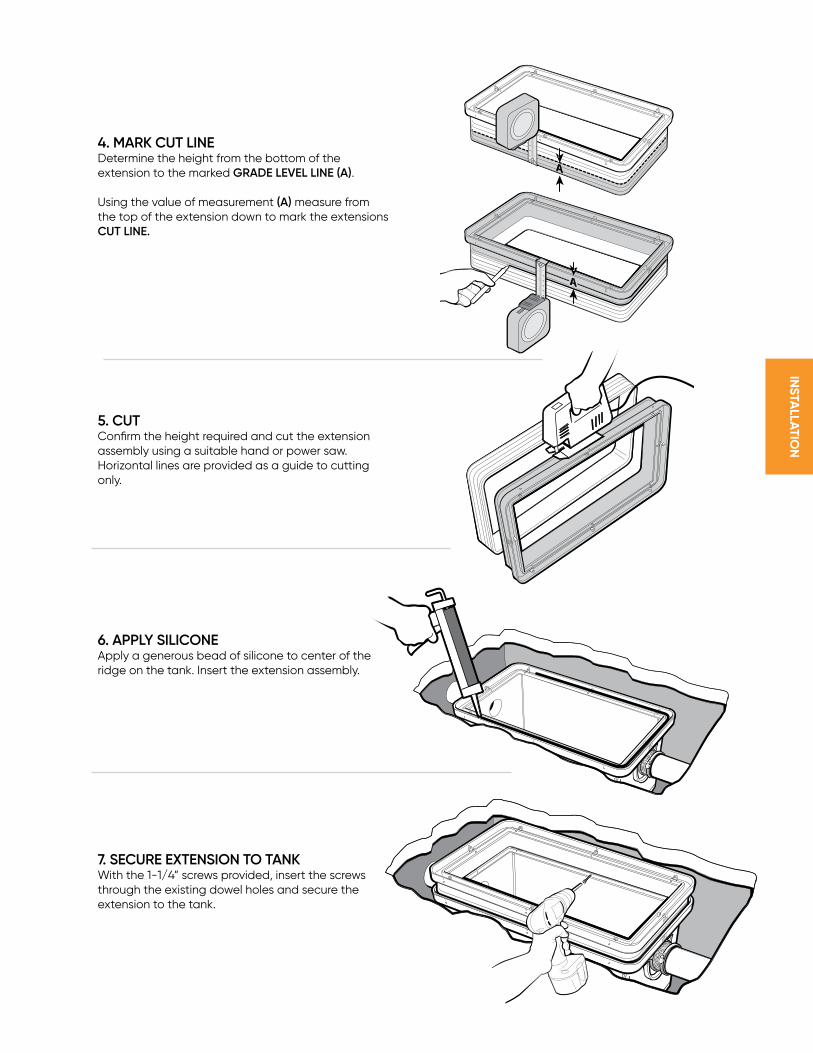
4. MARK CUT LINEDetermine the height from the bottom of the extension to the marked GRADE LEVEL LINE (A).
Using the value of measurement (A) measure from the top of the extension down to mark the extensions CUT LINE.
5. CUTConfirm the height required and cut the extension assembly using a suitable hand or power saw. Horizontal lines are provided as a guide to cutting only.
6. APPLY SILICONEApply a generous bead of silicone to center of the ridge on the tank. Insert the extension assembly.
7. SECURE EXTENSION TO TANKWith the 1-1/4” screws provided, insert the screws through the existing dowel holes and secure the extension to the tank.
A
AAA
33 Canplas® Endura® Grease Management
INS
TALL
AT
ION
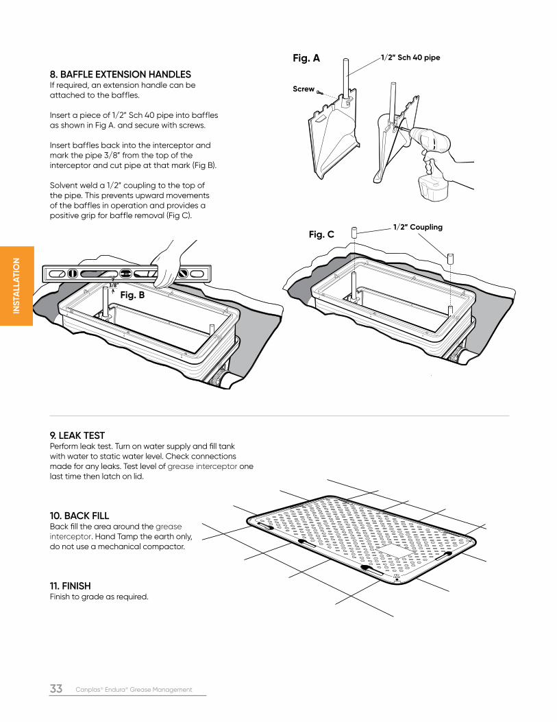
8. BAFFLE EXTENSION HANDLESIf required, an extension handle can be attached to the baffles.
Insert a piece of 1/2” Sch 40 pipe into baffles as shown in Fig A. and secure with screws.
Insert baffles back into the interceptor and mark the pipe 3/8” from the top of the interceptor and cut pipe at that mark (Fig B).
Solvent weld a 1/2” coupling to the top of the pipe. This prevents upward movements of the baffles in operation and provides a positive grip for baffle removal (Fig C).
9. LEAK TESTPerform leak test. Turn on water supply and fill tank with water to static water level. Check connections made for any leaks. Test level of grease interceptor one last time then latch on lid.
10. BACK FILLBack fill the area around the grease interceptor. Hand Tamp the earth only, do not use a mechanical compactor.
11. FINISHFinish to grade as required.
3/8”
PRYHERE
PRY
HER
E
Fig. A
Fig. B
Fig. C
1/2” Sch 40 pipe
1/2” Coupling
Screw
Canplas® Endura® Grease Management 34
INS
TALLA
TIO
N
Interceptor
A
B
Finished Flooror Grade Level
Cut Line
1-5/8”1-5/8”
C
Min. 6.1/2”Max 35”
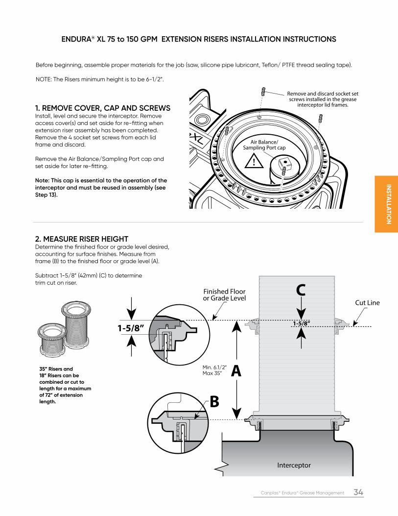
1. REMOVE COVER, CAP AND SCREWSInstall, level and secure the interceptor. Remove access cover(s) and set aside for re-fitting when extension riser assembly has been completed. Remove the 4 socket set screws from each lid frame and discard.
Remove the Air Balance/Sampling Port cap and set aside for later re-fitting.
Note: This cap is essential to the operation of the interceptor and must be reused in assembly (see Step 13).
2. MEASURE RISER HEIGHTDetermine the finished floor or grade level desired, accounting for surface finishes. Measure from frame (B) to the finished floor or grade level (A). Subtract 1-5/8” (42mm) (C) to determine trim cut on riser.
ENDURA® XL 75 to 150 GPM EXTENSION RISERS INSTALLATION INSTRUCTIONS
Before beginning, assemble proper materials for the job (saw, silicone pipe lubricant, Teflon/ PTFE thread sealing tape).
NOTE: The Risers minimum height is to be 6-1/2”.
35” Risers and 18” Risers can be combined or cut to length for a maximum of 72” of extension length.
Air Balance/Sampling Port cap
Remove and discard socket set screws installed in the grease
interceptor lid frames.
35 Canplas® Endura® Grease Management
INS
TALL
AT
ION
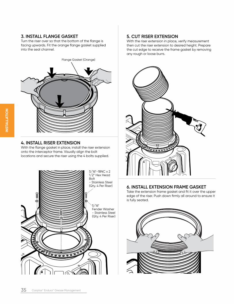
3. INSTALL FLANGE GASKETTurn the riser over so that the bottom of the flange is facing upwards. Fit the orange flange gasket supplied into the seal channel.
4. INSTALL RISER EXTENSIONWith the flange gasket in place, install the riser extension onto the interceptor frame. Visually align the bolt locations and secure the riser using the 4 bolts supplied.
5. CUT RISER EXTENSIONWith the riser extension in place, verify measurement then cut the riser extension to desired height. Prepare the cut edge to receive the frame gasket by removing any rough or loose burrs.
6. INSTALL EXTENSION FRAME GASKETTake the extension frame gasket and fit it over the upper edge of the riser. Push down firmly all around to ensure it is fully seated.
Flange Gasket (Orange)
5/16”-18NC x 2 1/2” Hex Head Bolt - Stainless Steel (Qty. 4 Per Riser)
5/16” Fender Washer - Stainless Steel (Qty. 4 Per Riser)
Canplas® Endura® Grease Management 36
INS
TALLA
TIO
N
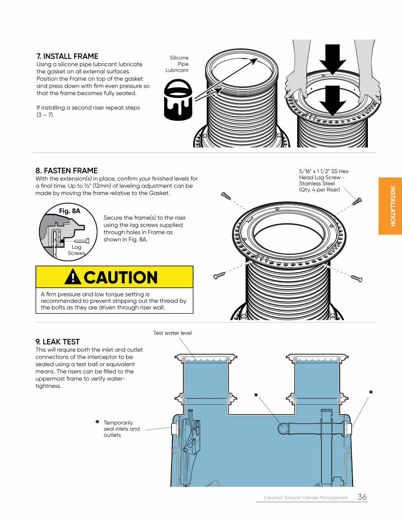
5/16” x 1 1/2” SS Hex Head Lag Screw - Stainless Steel(Qty. 4 per Riser)
Silicone Pipe
Lubricant
7. INSTALL FRAMEUsing a silicone pipe lubricant lubricate the gasket on all external surfaces. Position the Frame on top of the gasket and press down with firm even pressure so that the frame becomes fully seated.
If installing a second riser repeat steps (3 – 7).
8. FASTEN FRAMEWith the extension(s) in place, confirm your finished levels for a final time. Up to ½” (12mm) of leveling adjustment can be made by moving the frame relative to the Gasket.
9. LEAK TESTThis will require both the inlet and outlet connections of the interceptor to be sealed using a test ball or equivalent means. The risers can be filled to the uppermost frame to verify water-tightness.
Lag Screws
Fig. 8A
CAUTIONA firm pressure and low torque setting is recommended to prevent stripping out the thread by the bolts as they are driven through riser wall.
Secure the frame(s) to the riser using the lag screws supplied through holes in Frame as shown in Fig. 8A.
Temporarily seal inlets and outlets
Test water level
*
* *
37 Canplas® Endura® Grease Management
INS
TALL
AT
ION
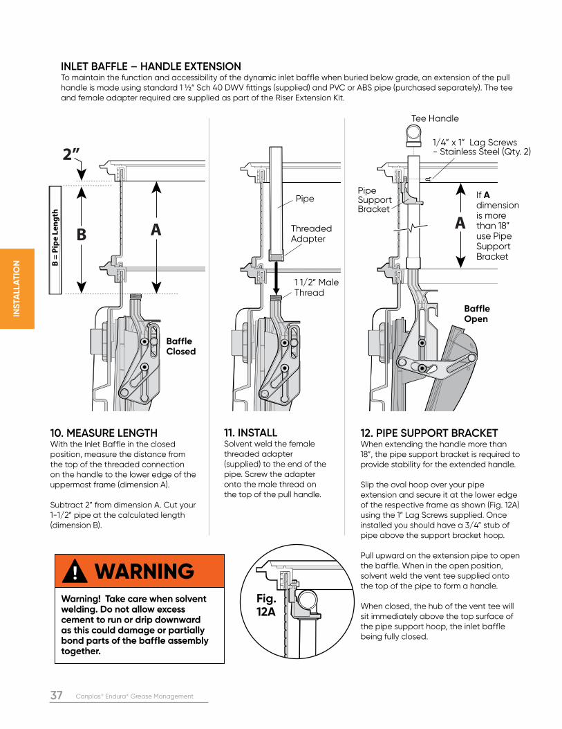
INLET BAFFLE – HANDLE EXTENSIONTo maintain the function and accessibility of the dynamic inlet baffle when buried below grade, an extension of the pull handle is made using standard 1 ½” Sch 40 DWV fittings (supplied) and PVC or ABS pipe (purchased separately). The tee and female adapter required are supplied as part of the Riser Extension Kit.
10. MEASURE LENGTHWith the Inlet Baffle in the closed position, measure the distance from the top of the threaded connection on the handle to the lower edge of the uppermost frame (dimension A).
Subtract 2” from dimension A. Cut your 1-1/2” pipe at the calculated length (dimension B).
11. INSTALLSolvent weld the female threaded adapter (supplied) to the end of the pipe. Screw the adapter onto the male thread on the top of the pull handle.
12. PIPE SUPPORT BRACKETWhen extending the handle more than 18”, the pipe support bracket is required to provide stability for the extended handle.
Slip the oval hoop over your pipe extension and secure it at the lower edge of the respective frame as shown (Fig. 12A) using the 1” Lag Screws supplied. Once installed you should have a 3/4” stub of pipe above the support bracket hoop.
Pull upward on the extension pipe to open the baffle. When in the open position, solvent weld the vent tee supplied onto the top of the pipe to form a handle.
When closed, the hub of the vent tee will sit immediately above the top surface of the pipe support hoop, the inlet baffle being fully closed.
Fig. 12A
B =
Pip
e L
en
gth
AB
2”
AThreadedAdapter
1 1/2” Male Thread
Baffle Closed
Pipe
Tee Handle
1/4” x 1” Lag Screws - Stainless Steel (Qty. 2)
Pipe Support Bracket
WARNINGWarning! Take care when solvent welding. Do not allow excess cement to run or drip downward as this could damage or partially bond parts of the baffle assembly together.
Baffle Open
If A dimension is more than 18” use PipeSupport Bracket
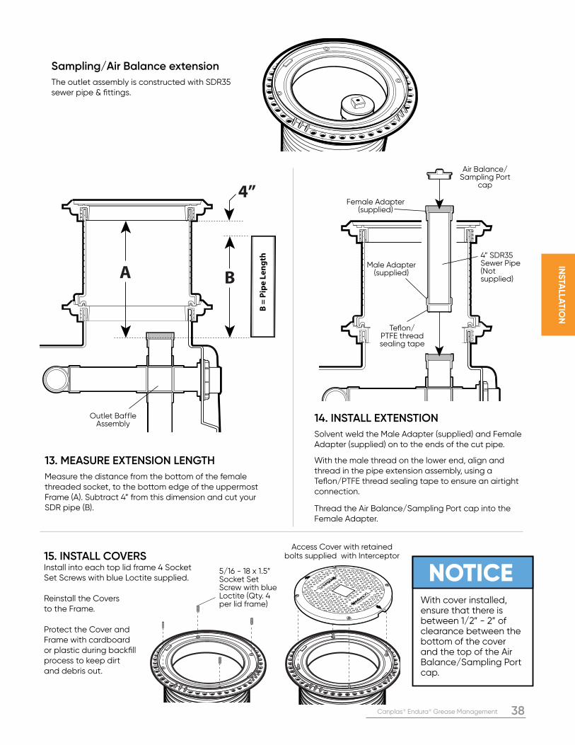
Canplas® Endura® Grease Management 38
INS
TALLA
TIO
N
Sampling/Air Balance extension
The outlet assembly is constructed with SDR35 sewer pipe & fittings.
13. MEASURE EXTENSION LENGTH
Measure the distance from the bottom of the female threaded socket, to the bottom edge of the uppermost Frame (A). Subtract 4” from this dimension and cut your SDR pipe (B).
14. INSTALL EXTENSTION
Solvent weld the Male Adapter (supplied) and Female Adapter (supplied) on to the ends of the cut pipe.
With the male thread on the lower end, align and thread in the pipe extension assembly, using a Teflon/PTFE thread sealing tape to ensure an airtight connection.
Thread the Air Balance/Sampling Port cap into the Female Adapter.
B =
Pip
e L
en
gth
A B
4”
Male Adapter (supplied)
Teflon/PTFE thread sealing tape
Outlet Baffle Assembly
4” SDR35 Sewer Pipe (Not supplied)
Female Adapter (supplied)
Air Balance/Sampling Port
cap
NOTICEWith cover installed, ensure that there is between 1/2” - 2” of clearance between the bottom of the cover and the top of the Air Balance/Sampling Port cap.
Access Cover with retained bolts supplied with Interceptor
GREASE INTERCEPTOR
GREASE INTERCEPTOR
5/16 - 18 x 1.5” Socket Set Screw with blue Loctite (Qty. 4 per lid frame)
15. INSTALL COVERSInstall into each top lid frame 4 Socket Set Screws with blue Loctite supplied.
Reinstall the Covers to the Frame. Protect the Cover and Frame with cardboard or plastic during backfill process to keep dirt and debris out.
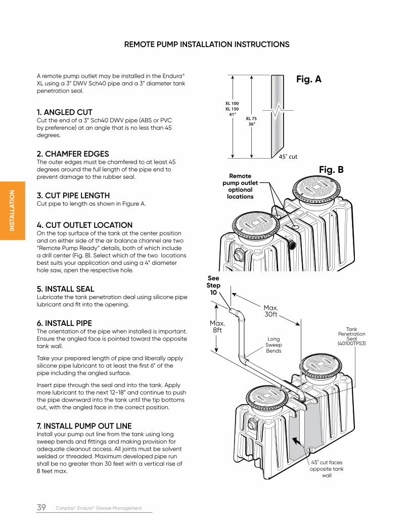
39 Canplas® Endura® Grease Management
INS
TALL
AT
ION
GREASE INTERCEPTOR
GREASE INTERCEPTOR
GREASE INTERCEPTOR
GREASE INTERCEPTOR
A remote pump outlet may be installed in the Endura® XL using a 3” DWV Sch40 pipe and a 3” diameter tank penetration seal.
1. ANGLED CUTCut the end of a 3” Sch40 DWV pipe (ABS or PVC by preference) at an angle that is no less than 45 degrees.
2. CHAMFER EDGESThe outer edges must be chamfered to at least 45 degrees around the full length of the pipe end to prevent damage to the rubber seal.
3. CUT PIPE LENGTHCut pipe to length as shown in Figure A.
4. CUT OUTLET LOCATION On the top surface of the tank at the center position and on either side of the air balance channel are two “Remote Pump Ready” details, both of which include a drill center (Fig. B). Select which of the two locations best suits your application and using a 4” diameter hole saw, open the respective hole.
5. INSTALL SEALLubricate the tank penetration deal using silicone pipe lubricant and fit into the opening.
6. INSTALL PIPEThe orientation of the pipe when installed is important. Ensure the angled face is pointed toward the opposite tank wall.
Take your prepared length of pipe and liberally apply silicone pipe lubricant to at least the first 6” of the pipe including the angled surface.
Insert pipe through the seal and into the tank. Apply more lubricant to the next 12-18” and continue to push the pipe downward into the tank until the tip bottoms out, with the angled face in the correct position.
7. INSTALL PUMP OUT LINEInstall your pump out line from the tank using long sweep bends and fittings and making provision for adequate cleanout access. All joints must be solvent welded or threaded. Maximum developed pipe run shall be no greater than 30 feet with a vertical rise of 8 feet max.
Max. 8ft
See Step
10
GREASE INTERCEPTOR
GREASE INTERCEPTOR
GREASE INTERCEPTOR
GREASE INTERCEPTOR
45˚ cut
XL 75
36”
XL 100
XL 150
41”
Remote pump outlet
optional locations
Fig. A
Fig. B
Max. 30ft
45˚ cut faces opposite tank
wall
Long Sweep Bends
Tank Penetration
Seal (40100TPS3)
REMOTE PUMP INSTALLATION INSTRUCTIONS
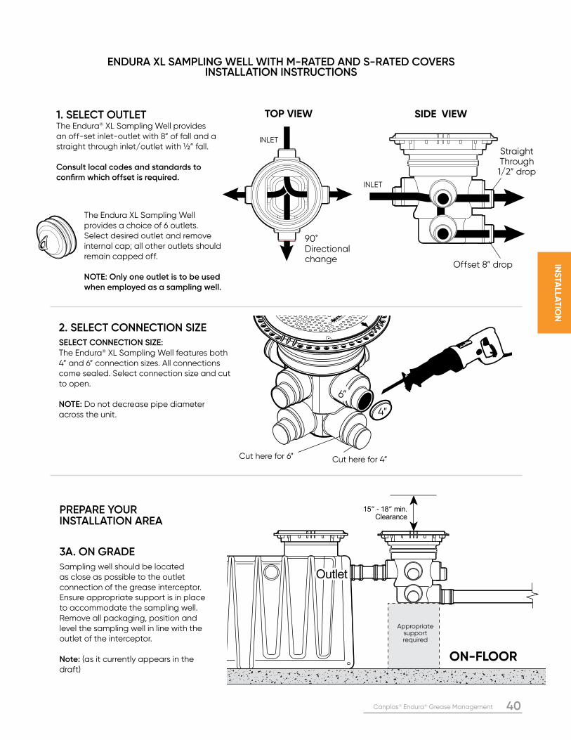
Canplas® Endura® Grease Management 40
INS
TALLA
TIO
N
TOP VIEW SIDE VIEW
90˚ Directional change
INLET
INLET
Straight Through1/2” drop
Offset 8” drop
ENDURA XL SAMPLING WELL WITH M-RATED AND S-RATED COVERS INSTALLATION INSTRUCTIONS
15” - 18” min.Clearance
OutletOutletOutlet
ON-FLOOR
Appropriate support required
PREPARE YOUR INSTALLATION AREA
3A. ON GRADESampling well should be located as close as possible to the outlet connection of the grease interceptor. Ensure appropriate support is in place to accommodate the sampling well. Remove all packaging, position and level the sampling well in line with the outlet of the interceptor.
Note: (as it currently appears in the draft)
The Endura XL Sampling Well provides a choice of 6 outlets. Select desired outlet and remove internal cap; all other outlets should remain capped off.
NOTE: Only one outlet is to be used when employed as a sampling well.
1. SELECT OUTLET The Endura® XL Sampling Well provides an off-set inlet-outlet with 8” of fall and a straight through inlet/outlet with ½” fall.
Consult local codes and standards to confirm which offset is required.
2. SELECT CONNECTION SIZESELECT CONNECTION SIZE: The Endura® XL Sampling Well features both 4” and 6” connection sizes. All connections come sealed. Select connection size and cut to open.
NOTE: Do not decrease pipe diameter across the unit.
GREASE INT
Cut here for 6” Cut here for 4”
4”
6”
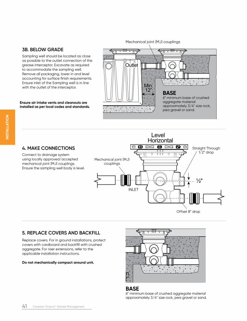
41 Canplas® Endura® Grease Management
INS
TALL
AT
ION
3B. BELOW GRADESampling well should be located as close as possible to the outlet connection of the grease interceptor. Excavate as required to accommodate the sampling well. Remove all packaging, lower in and level accounting for surface finish requirements. Ensure inlet of the Sampling well is in line with the outlet of the interceptor.
4. MAKE CONNECTIONSConnect to drainage system using locally approved/accepted mechanical joint (MJ) couplings. Ensure the sampling well body is level.
5. REPLACE COVERS AND BACKFILL Replace covers. For in ground installations, protect covers with cardboard and backfill with crushed aggregate. For riser extensions, refer to the applicable installation instructions.
Do not mechanically compact around unit.
Level Horizontal
½"
Straight Through1/2” drop
INLET
Mechanical joint (MJ) couplings
Offset 8” drop
Min.Min.12”12”Min.12”
OutletOutletOutlet
Min.Min.12”12”Min.12”
Mechanical joint (MJ) couplings
BASE 6” minimum base of crushed aggregate material approximately 3/4” size rock, pea gravel or sand.
BASE 6” minimum base of crushed aggregate material approximately 3/4” size rock, pea gravel or sand.
Ensure air intake vents and cleanouts are installed as per local codes and standards.
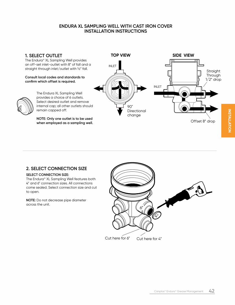
Canplas® Endura® Grease Management 42
INS
TALLA
TIO
N
ENDURA XL SAMPLING WELL WITH CAST IRON COVER INSTALLATION INSTRUCTIONS
Cut here for 6” Cut here for 4”
4”
6”
TOP VIEW SIDE VIEW
90˚ Directional change
INLET
INLET
Straight Through1/2” drop
Offset 8” drop
The Endura XL Sampling Well provides a choice of 6 outlets. Select desired outlet and remove internal cap; all other outlets should remain capped off.
NOTE: Only one outlet is to be used when employed as a sampling well.
1. SELECT OUTLET The Endura® XL Sampling Well provides an off-set inlet-outlet with 8” of fall and a straight through inlet/outlet with ½” fall.
Consult local codes and standards to confirm which offset is required.
2. SELECT CONNECTION SIZESELECT CONNECTION SIZE: The Endura® XL Sampling Well features both 4” and 6” connection sizes. All connections come sealed. Select connection size and cut to open.
NOTE: Do not decrease pipe diameter across the unit.
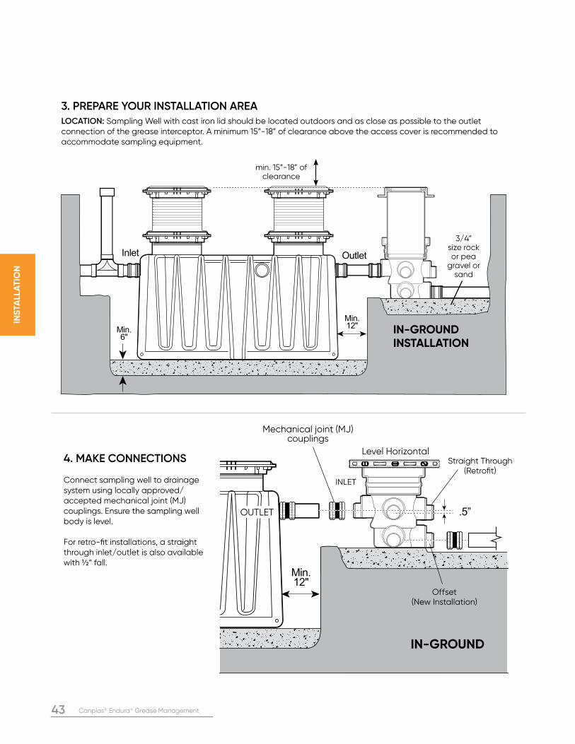
43 Canplas® Endura® Grease Management
INS
TALL
AT
ION
4. MAKE CONNECTIONS
Connect sampling well to drainage system using locally approved/accepted mechanical joint (MJ) couplings. Ensure the sampling well body is level.
For retro-fit installations, a straight through inlet/outlet is also available with ½” fall.
Inlet Outlet
Min.12"
Min.6"
min. 15”-18” of clearance
IN-GROUNDINSTALLATION
3. PREPARE YOUR INSTALLATION AREALOCATION: Sampling Well with cast iron lid should be located outdoors and as close as possible to the outlet connection of the grease interceptor. A minimum 15”-18” of clearance above the access cover is recommended to accommodate sampling equipment.
Min.12"
.5”
IN-GROUND
Mechanical joint (MJ) couplings
Level Horizontal
INLET
OUTLETOUTLET
Straight Through(Retrofit)
Offset (New Installation)
3/4” size rock or pea
gravel or sand
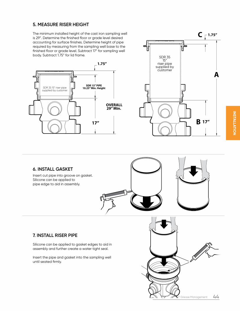
Canplas® Endura® Grease Management 44
INS
TALLA
TIO
N
SDR 15” PIPE10.25” Min. Height
1.75”
17”
OVERALL29” Min.
1.75”
A
B
C
17”
SDR 35 15” riser pipe supplied by customer
SDR 35 15”
riser pipe supplied by
customer
5. MEASURE RISER HEIGHT
The minimum installed height of the cast iron sampling well is 29”. Determine the finished floor or grade level desired accounting for surface finishes. Determine height of pipe required by measuring from the sampling well base to the finished floor or grade level. Subtract 17” for sampling well body. Subtract 1.75” for lid frame.
6. INSTALL GASKETInsert cut pipe into groove on gasket. Silicone can be applied to pipe edge to aid in assembly.
7. INSTALL RISER PIPE
Silicone can be applied to gasket edges to aid in assembly and further create a water tight seal.
Insert the pipe and gasket into the sampling well until seated firmly.
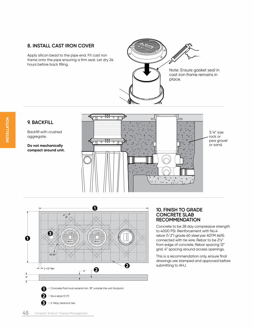
45 Canplas® Endura® Grease Management
INS
TALL
AT
ION
Note: Ensure gasket seal in cast iron frame remains in place.
3/4” size rock or pea gravel or sand.
45.00°
2 1/2" Min.
8"
4"
4"
• Concrete Pad must extend min. 18” outside the unit footprint.
• No.4 rebar (1/2”)
• 2-Way cleanout tee
8. INSTALL CAST IRON COVER
Apply silicon bead to the pipe end. Fit cast iron frame onto the pipe ensuring a firm seal. Let dry 24 hours before back filling.
9. BACKFILL
Backfill with crushed aggregate.
Do not mechanically compact around unit.
10. FINISH TO GRADECONCRETE SLAB RECOMMENDATIONConcrete to be 28 day compressive strength to 4000 PSI. Reinforcement with No.4 rebar (1/2”) grade 60 steel per ASTM A615: connected with tie wire. Rebar to be 2½” from edge of concrete. Rebar spacing 12” grid. 4” spacing around access openings. This is a recommendation only, ensure final drawings are stamped and approved before submitting to AHJ.
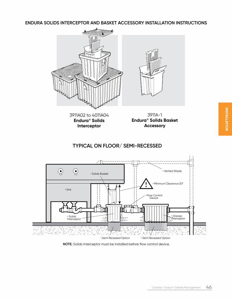
Canplas® Endura® Grease Management 46
INS
TALLA
TIO
N
3911A-1 Endura® Solids Basket
Accessory
3911A02 to 4011A04 Endura® Solids
Interceptor
ENDURA SOLIDS INTERCEPTOR AND BASKET ACCESSORY INSTALLATION INSTRUCTIONS
NOTE: Solids Interceptor must be installed before flow control device.
TYPICAL ON FLOOR/ SEMI-RECESSED
• Flow Control Device
• Solids Interceptor
• Solids Basket• Vented Waste
• Minimum Clearance 20”
• Grease Interceptor
• Sink
• Semi Recessed Option • Semi Recessed Option
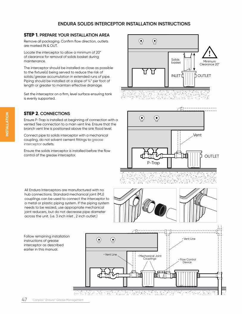
47 Canplas® Endura® Grease Management
INS
TALL
AT
ION
ENDURA SOLIDS INTERCEPTOR INSTALLATION INSTRUCTIONS
STEP 1. PREPARE YOUR INSTALLATION AREA
Remove all packaging. Confirm flow direction, outlets are marked IN & OUT.
Locate the interceptor to allow a minimum of 20” of clearance for removal of solids basket during maintenance.
The interceptor should be installed as close as possible to the fixture(s) being served to reduce the risk of solids/grease accumulation in extended runs of pipe. Piping should be installed at a slope of ¼” per foot of length or greater to maintain effective drainage.
Set the interceptor on a firm, level surface ensuring tank is evenly supported.
STEP 2. CONNECTIONS
Ensure P-Trap is installed at beginning of connection with a vented Tee connection to a main vent line. Ensure that the branch vent line is positioned above the sink flood level.
Connect pipe to solids interceptor with a mechanical coupling, do not solvent cement fittings to grease interceptor outlets.
Ensure the solids interceptor is installed before the flow control of the grease interceptor.
• Flow Control Device
• Vent Line
• Vent Line • Mechanical Joint Couplings
Follow remaining installation instructions of grease interceptor as described earlier in this manual.
Minimum Clearance 20”
Solids basket
INLET OUTLET
OUTLET
P-Trap
Vent
All Endura Interceptors are manufactured with no hub connections. Standard mechanical joint (MJ) couplings can be used to connect the interceptor to a metal or plastic piping system. If the piping system needs to be resized, use appropriate mechanical joint reducers, but do not decrease pipe diameter across the unit. (i.e. 3 inch inlet , 2 inch outlet.)
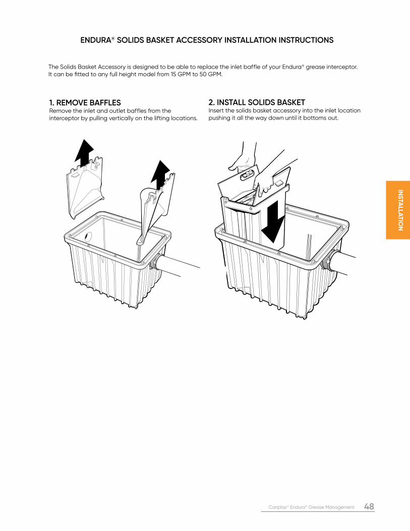
Canplas® Endura® Grease Management 48
INS
TALLA
TIO
N
The Solids Basket Accessory is designed to be able to replace the inlet baffle of your Endura® grease interceptor. It can be fitted to any full height model from 15 GPM to 50 GPM.
1. REMOVE BAFFLESRemove the inlet and outlet baffles from the interceptor by pulling vertically on the lifting locations.
2. INSTALL SOLIDS BASKETInsert the solids basket accessory into the inlet location pushing it all the way down until it bottoms out.
ENDURA® SOLIDS BASKET ACCESSORY INSTALLATION INSTRUCTIONS
49 Canplas® Endura® Grease Management
SY
ST
EM
OP
ER
AT
ION
, M
AIN
TE
NA
NC
E A
ND
RE
PA
IRS
KITCHEN BEST MANAGEMENT PRACTICESRECOMMENDED BEST MANAGEMENT PRACTICES (BMP’s) for FOOD SERVICE ESTABLISHMENTS*Owners and operators of food service establishments are encouraged to implement the following BMP’s to help improve the quality of wastewater discharged to drains and sewers. Please check with your municipal plumbing code or wastewater department policies to determine conformance criteria for the proper handling of wastewater.
1. Put signs in the kitchen, particularly over the sink, telling staff what can and what cannot go down the drains.
2. Do not pour oil, grease or large amounts of oily liquids such as gravies, sauces or salad dressings down the drain. Collect this material in a secure waste-grease container for disposal at approved locations.
3. Scrape off greasy trays and pans into a waste-grease container before putting them into a sink or dishwasher.
4. Scrape food waste from pots, pans and dishes into a garbage bin before putting them into a sink or dishwasher.
5. Put a fine basket strainer in sink drains to catch solids as well as dishwasher discharge to catch items such as rice and corn.
6. Install a special-purpose solids interceptor upstream of the grease interceptor to capture solid particles. Solids take up space and interfere with oil and grease separation. Also, food-waste solids that collect in a grease interceptor will decay and cause odor problems.
7. Do not pour coffee grounds or tea leaves down the drain.
8. Develop and implement a plan to reduce, reuse and recycle waste
• Use a recycling service for your used cooking oil. Used cooking oil can be recycled into useful products such as soap, animal feed and biodiesel products. • Separate out food waste for delivery to a centralized composting site.
9. Cleaning grease off kitchen exhaust systems. Grease that builds up on exhaust hoods, filters, ducts and fans is usually removed and cleaned to the bare metal by a certified service company. The following cleaning procedure is recommended: • Use hand scrapers to remove as much grease as possible from the exhaust system. Collect and store the grease in a separate container labeled “waste grease.” • Wash the exhaust system with a caustic cleaning solution, collecting the water in a bucket. • Neutralize the wash water in the bucket by adding a weak acid such as lemon juice, citric acid or a little vinegar. • Skim off any grease floating in the bucket and store it in the waste-grease container. • Pour the neutralized water from the bucket into a drain that is connected to a grease interceptor. Be careful not to pour the solids at the bottom of the bucket into the drain. Store the solids in the waste-grease container.
* Greater Vancouver Regional District (GVRD), “Best Management Practices & Code Practices for Waste Water Management at Food Sector Establishments”, Nov. 2001, pp 8, 10.
CLEANING & MAINTENANCEAll grease interceptors must be cleaned regularly to maintain efficient operation. Endura® recommends a licensed and locally approved service provider manage the regular removal, cleaning and disposal of the fats, oil and grease that is captured in your interceptor. For point of use units (7 GPM – 50 GPM) that will be maintained by Food Service Establishment FSE staff, make sure training is provided in: • proper function, operation and maintenance of grease interceptors outlined in this manual • proper storage, handling and disposal of wastes • proper separation and storage of materials • proper use and handling of cleaning aids • proper housekeeping • local code requirements and Best Management Practices for food sector facilities.
CAUTIONFailure to maintain the grease interceptor can result in back-ups, flooding and property damage.
SECTION FIVE: SYSTEM OPERATION, MAINTENANCE AND REPAIRS
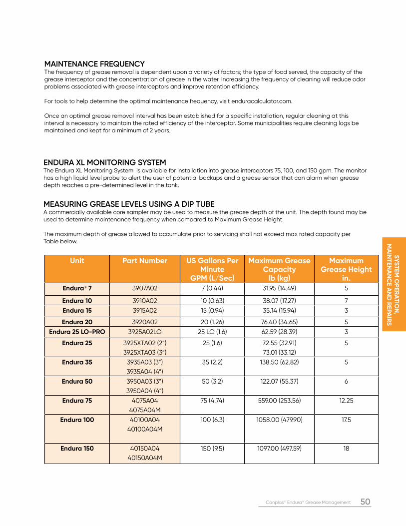
Canplas® Endura® Grease Management 50
SY
ST
EM
OP
ER
AT
ION
, M
AIN
TE
NA
NC
E A
ND
RE
PA
IRS
MAINTENANCE FREQUENCYThe frequency of grease removal is dependent upon a variety of factors; the type of food served, the capacity of the grease interceptor and the concentration of grease in the water. Increasing the frequency of cleaning will reduce odor problems associated with grease interceptors and improve retention efficiency.
For tools to help determine the optimal maintenance frequency, visit enduracalculator.com. Once an optimal grease removal interval has been established for a specific installation, regular cleaning at this interval is necessary to maintain the rated efficiency of the interceptor. Some municipalities require cleaning logs be maintained and kept for a minimum of 2 years.
Unit Part Number US Gallons Per Minute
GPM (L/Sec)
Maximum Grease Capacity
lb (kg)
Maximum Grease Height
in.Endura® 7 3907A02 7 (0.44) 31.95 (14.49) 5
Endura 10 3910A02 10 (0.63) 38.07 (17.27) 7
Endura 15 3915A02 15 (0.94) 35.14 (15.94) 3
Endura 20 3920A02 20 (1.26) 76.40 (34.65) 5
Endura 25 LO-PRO 3925A02LO 25 LO (1.6) 62.59 (28.39) 3
Endura 25 3925XTA02 (2”)
3925XTA03 (3”)
25 (1.6) 72.55 (32.91)
73.01 (33.12)
5
Endura 35 3935A03 (3”)
3935A04 (4”)
35 (2.2) 138.50 (62.82) 5
Endura 50 3950A03 (3”)
3950A04 (4”)
50 (3.2) 122.07 (55.37) 6
Endura 75 4075A04
4075A04M
75 (4.74) 559.00 (253.56) 12.25
Endura 100 40100A04
40100A04M
100 (6.3) 1058.00 (479.90) 17.5
Endura 150 40150A04
40150A04M
150 (9.5) 1097.00 (497.59) 18
MEASURING GREASE LEVELS USING A DIP TUBEA commercially available core sampler may be used to measure the grease depth of the unit. The depth found may be used to determine maintenance frequency when compared to Maximum Grease Height.
The maximum depth of grease allowed to accumulate prior to servicing shall not exceed max rated capacity per Table below.
ENDURA XL MONITORING SYSTEMThe Endura XL Monitoring System is available for installation into grease interceptors 75, 100, and 150 gpm. The monitor has a high liquid level probe to alert the user of potential backups and a grease sensor that can alarm when grease depth reaches a pre-determined level in the tank.
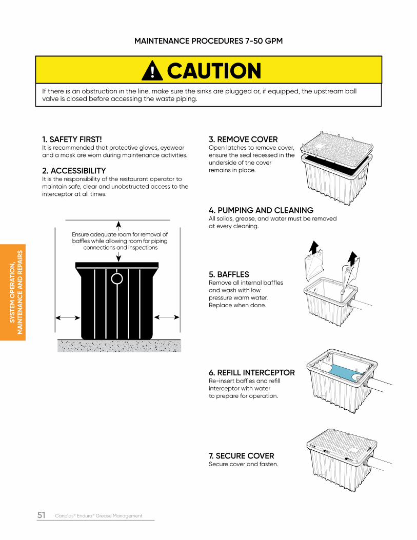
51 Canplas® Endura® Grease Management
SY
ST
EM
OP
ER
AT
ION
, M
AIN
TE
NA
NC
E A
ND
RE
PA
IRS
3. REMOVE COVEROpen latches to remove cover, ensure the seal recessed in the underside of the cover remains in place.
4. PUMPING AND CLEANINGAll solids, grease, and water must be removed at every cleaning.
5. BAFFLESRemove all internal bafflesand wash with low pressure warm water. Replace when done.
6. REFILL INTERCEPTORRe-insert baffles and refill interceptor with water to prepare for operation.
7. SECURE COVERSecure cover and fasten.
MAINTENANCE PROCEDURES 7-50 GPM
1. SAFETY FIRST!It is recommended that protective gloves, eyewear and a mask are worn during maintenance activities.
2. ACCESSIBILITYIt is the responsibility of the restaurant operator to maintain safe, clear and unobstructed access to the interceptor at all times.
CAUTIONIf there is an obstruction in the line, make sure the sinks are plugged or, if equipped, the upstream ball valve is closed before accessing the waste piping.
Ensure adequate room for removal of baffles while allowing room for piping
connections and inspections
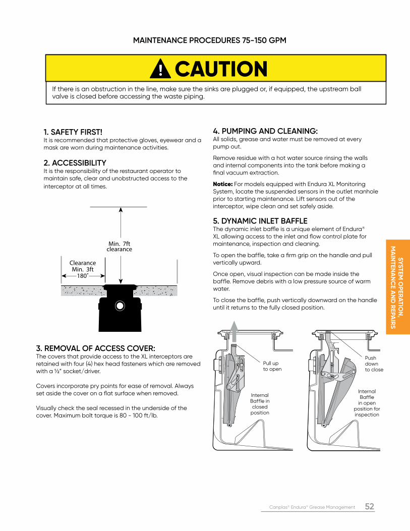
Canplas® Endura® Grease Management 52
SY
ST
EM
OP
ER
AT
ION
, M
AIN
TE
NA
NC
E A
ND
RE
PA
IRS
4. PUMPING AND CLEANING:All solids, grease and water must be removed at every pump out.
Remove residue with a hot water source rinsing the walls and internal components into the tank before making a final vacuum extraction.
Notice: For models equipped with Endura XL Monitoring System, locate the suspended sensors in the outlet manhole prior to starting maintenance. Lift sensors out of the interceptor, wipe clean and set safely aside.
5. DYNAMIC INLET BAFFLEThe dynamic inlet baffle is a unique element of Endura® XL allowing access to the inlet and flow control plate for maintenance, inspection and cleaning.
To open the baffle, take a firm grip on the handle and pull vertically upward.
Once open, visual inspection can be made inside the baffle. Remove debris with a low pressure source of warm water.
To close the baffle, push vertically downward on the handle until it returns to the fully closed position.
3. REMOVAL OF ACCESS COVER:The covers that provide access to the XL interceptors are retained with four (4) hex head fasteners which are removed with a ½” socket/driver.
Covers incorporate pry points for ease of removal. Always set aside the cover on a flat surface when removed.
Visually check the seal recessed in the underside of the cover. Maximum bolt torque is 80 - 100 ft/lb.
Pull upto open
Push down to close
Internal Baffle in closed
position
Internal Baffle
in open position for inspection
ClearanceMin. 3ft
180˚
Min. 7ftclearance
1. SAFETY FIRST!It is recommended that protective gloves, eyewear and a mask are worn during maintenance activities.
2. ACCESSIBILITYIt is the responsibility of the restaurant operator to maintain safe, clear and unobstructed access to the
interceptor at all times.
MAINTENANCE PROCEDURES 75-150 GPM
CAUTIONIf there is an obstruction in the line, make sure the sinks are plugged or, if equipped, the upstream ball valve is closed before accessing the waste piping.
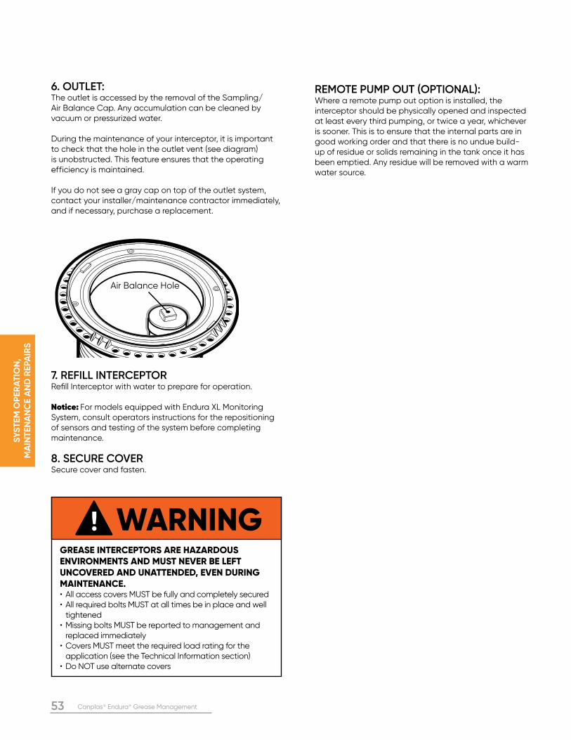
53 Canplas® Endura® Grease Management
SY
ST
EM
OP
ER
AT
ION
, M
AIN
TE
NA
NC
E A
ND
RE
PA
IRS
6. OUTLET: The outlet is accessed by the removal of the Sampling/ Air Balance Cap. Any accumulation can be cleaned by vacuum or pressurized water.
During the maintenance of your interceptor, it is important to check that the hole in the outlet vent (see diagram) is unobstructed. This feature ensures that the operating efficiency is maintained.
If you do not see a gray cap on top of the outlet system, contact your installer/maintenance contractor immediately, and if necessary, purchase a replacement.
7. REFILL INTERCEPTORRefill Interceptor with water to prepare for operation.
Notice: For models equipped with Endura XL Monitoring System, consult operators instructions for the repositioning of sensors and testing of the system before completing maintenance.
8. SECURE COVERSecure cover and fasten.
Air Balance Hole
WARNINGGREASE INTERCEPTORS ARE HAZARDOUS ENVIRONMENTS AND MUST NEVER BE LEFT UNCOVERED AND UNATTENDED, EVEN DURING MAINTENANCE. • All access covers MUST be fully and completely secured• All required bolts MUST at all times be in place and well tightened• Missing bolts MUST be reported to management and replaced immediately• Covers MUST meet the required load rating for the application (see the Technical Information section)• Do NOT use alternate covers
REMOTE PUMP OUT (OPTIONAL): Where a remote pump out option is installed, the interceptor should be physically opened and inspected at least every third pumping, or twice a year, whichever is sooner. This is to ensure that the internal parts are in good working order and that there is no undue build-up of residue or solids remaining in the tank once it has been emptied. Any residue will be removed with a warm water source.
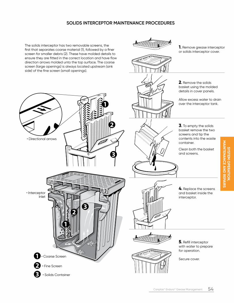
Canplas® Endura® Grease Management 54
SY
ST
EM
OP
ER
AT
ION
, M
AIN
TE
NA
NC
E A
ND
RE
PA
IRS
1. Remove grease interceptor or solids interceptor cover.
2. Remove the solids basket using the molded details in cover panels.
Allow excess water to drain over the interceptor tank.
3. To empty the solids basket remove the two screens and tip the contents into the waste container.
Clean both the basket and screens.
4. Replace the screens and basket inside the interceptor.
5. Refill interceptor with water to prepare for operation. Secure cover.
SOLIDS INTERCEPTOR MAINTENANCE PROCEDURES
The solids interceptor has two removable screens, the first that separates coarse material (1), followed by a finer screen for smaller debris (2). These have molded details to ensure they are fitted in the correct location and have flow direction arrows molded unto the top surface. The coarse screen (large openings) is always located upstream (sink side) of the fine screen (small openings).
• Directional arrows
• Interceptor Inlet
• Solids Container
• Coarse Screen
• Fine Screen
55 Canplas® Endura® Grease Management
FR
EQ
UE
NT
LY A
SK
ED
QU
ES
TIO
NS
A
ND
TR
OU
BLE
SH
OO
TIN
G
DO ENDURA® XL TANKS NEED TO BE DIRECTLY VENTED? Unless specifically mandated by local code or bylaw, Endura® XL tanks DO NOT require direct venting. Venting is required on the downstream drain like most plumbing appliances and fixtures.
DO I NEED TO INSTALL A CLEAN OUT BEFORE OR AFTER AN INTERCEPTOR? Most plumbing codes require an upstream and downstream cleanout immediately before and after the interceptor.
DO I HAVE TO INSTALL THE FLOW CONTROL DEVICE? The Flow Control is essential to the performance of the interceptor. It must be installed as indicated. Without it, the interceptor does not meet the requirements of the applicable standards.
MY JURISDICTION REQUIRES EFFLUENT SAMPLING VIA A DOWNSTREAM ACCESS. WHAT DO I DO? For those jurisdictions that require the capability to sample, Endura XL incorporates a sampling port within the outlet assembly. This is accessed by the removal of the air balance/sample port cap allowing water quality samples to be taken for analysis. Some AHJ’s may require a separate downstream sampling point. The Endura sampling well can provide a flexible solution for these applications.
WHAT FIXTURES SHOULD BE CONNECTED TO THE INTERCEPTOR? A grease interceptor should never receive sanitary wastewater discharge. Wastewater discharge to a grease interceptor will be from foodservice activities only. The requirements for appliances and fixtures that must and must not be connected to a grease interceptor is typically defined by your local plumbing codes and or jurisdictional by-laws.
HOW OFTEN SHOULD AN INTERCEPTOR BE CLEANED? Cleaning frequency depends on several factors. We recommend using the maintenance interval calculator at enduracalculator.com to help anticipate cleaning frequency.
HOW MUCH WILL IT COST TO MAINTAIN MY ENDURA XL INSTALLATION? Endura XL units are significantly more compact (less internal volume) than their equivalent GGI counterparts. Pumping is typically charged by the volume of gallons removed, so the ongoing maintenance will be proportionally less as well. Rates will vary significantly by region and by contractor. Always use a licensed or approved contractor to maintain your interceptor.
CAN I INSTALL MORE THAN ONE ENDURA XL UNIT IF MY JURISDICTION NEEDS A MINIMUM CAPACITY BY CODE? Depending on your jurisdiction, Endura XL may be installed in parallel and series installations. Consult local requirements.
I HEARD THAT PLASTIC TANKS CAN FLOAT IN HIGH WATER TABLE AREAS, PARTICULARLY WHEN PUMPED OUT FOR CLEANING. IS THIS TRUE?Yes it is, however Endura® XL is specifically designed to address this challenge. The Endura XL tanks are narrower at the top than the bottom and feature corrugations along the sides. The broad base provides stability and substantial resistance to being forced upward by water or freeze-thaw action. These features anchor the tank in the ground once backfilled. For areas of particular concern, an 8” concrete slab can be poured around the base to introduce further resistance.
SECTION SIX: FREQUENTLY ASKED QUESTIONS AND TROUBLESHOOTING
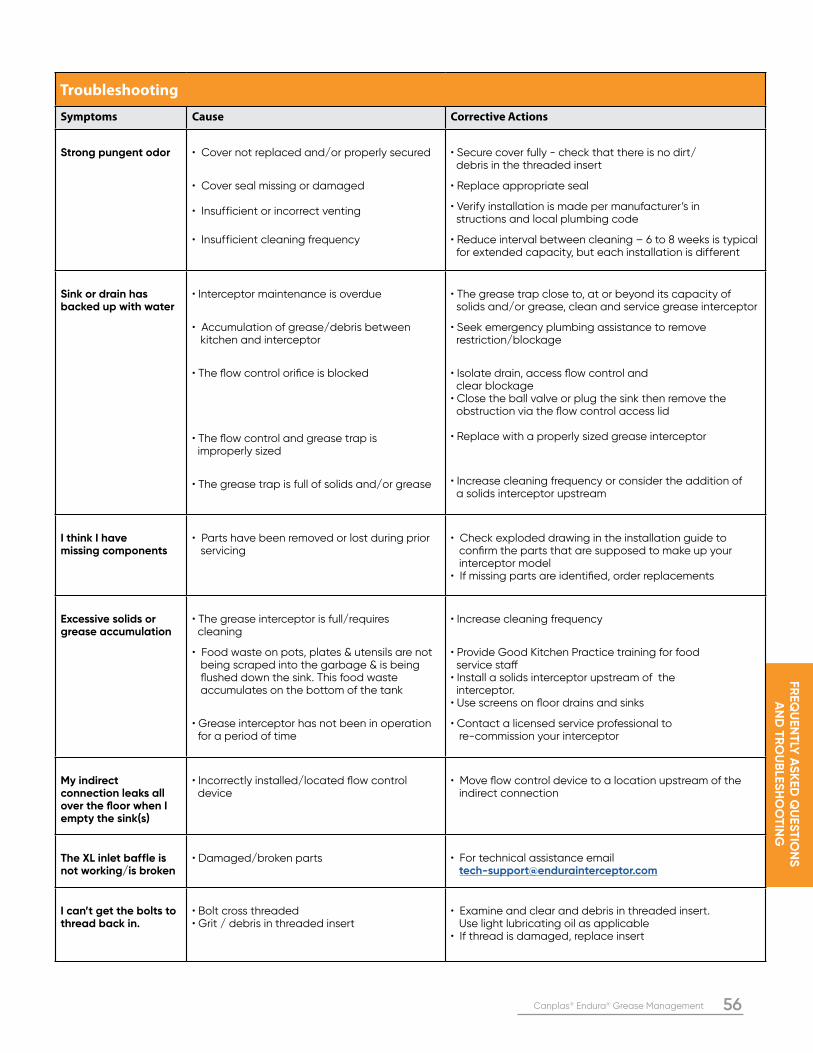
Canplas® Endura® Grease Management 56
FR
EQ
UE
NT
LY A
SK
ED
QU
ES
TIO
NS
A
ND
TR
OU
BLE
SH
OO
TIN
G
Troubleshooting
Symptoms Cause Corrective Actions
Strong pungent odor • Cover not replaced and/or properly secured
• Cover seal missing or damaged
• Insufficient or incorrect venting
• Insufficient cleaning frequency
• Secure cover fully - check that there is no dirt/ debris in the threaded insert • Replace appropriate seal • Verify installation is made per manufacturer’s in structions and local plumbing code • Reduce interval between cleaning – 6 to 8 weeks is typical for extended capacity, but each installation is different
Sink or drain has backed up with water
• Interceptor maintenance is overdue
• Accumulation of grease/debris between kitchen and interceptor
• The flow control orifice is blocked
• The flow control and grease trap is improperly sized
• The grease trap is full of solids and/or grease
• The grease trap close to, at or beyond its capacity of solids and/or grease, clean and service grease interceptor • Seek emergency plumbing assistance to remove restriction/blockage
• Isolate drain, access flow control and clear blockage• Close the ball valve or plug the sink then remove the obstruction via the flow control access lid
• Replace with a properly sized grease interceptor
• Increase cleaning frequency or consider the addition of a solids interceptor upstream
I think I have missing components
• Parts have been removed or lost during prior servicing
• Check exploded drawing in the installation guide to confirm the parts that are supposed to make up your interceptor model• If missing parts are identified, order replacements
Excessive solids or grease accumulation
• The grease interceptor is full/requires cleaning • Food waste on pots, plates & utensils are not being scraped into the garbage & is being flushed down the sink. This food waste accumulates on the bottom of the tank
• Grease interceptor has not been in operation for a period of time
• Increase cleaning frequency
• Provide Good Kitchen Practice training for food service staff• Install a solids interceptor upstream of the interceptor. • Use screens on floor drains and sinks
• Contact a licensed service professional to re-commission your interceptor
My indirect connection leaks all over the floor when I empty the sink(s)
• Incorrectly installed/located flow control device
• Move flow control device to a location upstream of the indirect connection
The XL inlet baffle is not working/is broken
• Damaged/broken parts • For technical assistance email [email protected]
I can’t get the bolts to thread back in.
• Bolt cross threaded• Grit / debris in threaded insert
• Examine and clear and debris in threaded insert. Use light lubricating oil as applicable• If thread is damaged, replace insert
57 Canplas® Endura® Grease Management
SP
EC
IFIC
AT
ION
S
SP
EC
IFIC
AT
ION
SSECTION SEVEN: SPECIFICATIONS
7-50 GPM ENDURA® INTERCEPTORS
MATERIAL• The body, lid and internal components shall be made of corrosion resistant, high impact PP compound that can withstand operational temperatures up to 220 degree F
CONNECTIONS• Shall be no-hub mechanical joint PP end connectors, IPS spigot PP end connectors or female NPT threaded PP end connectors
DESIGN FEATURES• Lid shall utilize a quick access latching system and be rated to support 300lbs• Internal features shall be removable or allow access for easy cleaning• Risers shall allow for below grade installations of 15 – 50 GPM interceptors to be extended to grade, up to a maximum of 18”• A flow control device with integrated air intake shall be provided with the interceptor for external flow control type installations
EFFICIENCY RATING• All interceptors shall be rated to an average efficiency per ASME A112.14.3• The maximum grease capacity of each grease interceptor shall be provided per ASME A112.14.3
MARKINGS• All interceptors shall be marked with the manufacturers name or trademark, model number, rated flow(s), “inlet” and “outlet”, nominal inlet size, applicable standard designations, access cover load classification, efficiency at the minimum grease capacity per ASME A112.14.3, and flow control model number for external flow control type installations
STANDARDS AND LISTING• All interceptors shall be certified to ASME A112.14.3, PDI-G101, or CSA B481.1, and have UPC listing
75-150 GPM ENDURA XL INTERCEPTORS
MATERIAL• The body, lid and internal components shall be made of corrosion resistant thermoplastics that can withstand operational temperatures up to 160 degree F. • The interceptor body shall be constructed of high density polyethylene
CONNECTIONS• Shall be hub mechanical joint PP end connectors or female NPT threaded PP end connectors
DESIGN FEATURES• Lids shall be Special duty traffic rated Type ‘S’ to support 10,000lbs or Medium duty (light vehicular traffic) rated Type ‘M’ to support 2,000lbs, per CSA B481.0 or Cast iron ASTM A48 30B lids meeting H20 loading standards • Internal features shall be removable or allow access for easy cleaning• Risers shall allow for below grade installations of 75 – 150 GPM interceptors to be extended to grade, up to a maximum of 72” • A flow control device with integrated air intake shall be provided with the interceptor for external flow control type installations
EFFICIENCY RATING• All interceptors shall be rated to an average efficiency per ASME A112.14.3 • The maximum grease capacity of each grease interceptor shall be provided per ASME A112.14.3
MARKINGS• All interceptors shall be marked with the manufacturers name or trademark, model number, rated flow(s), “inlet” and “outlet”, nominal inlet size, applicable standard designations, access cover load classification, efficiency at the minimum grease capacity per ASME A112.14.3, and flow control model number for external flow control type installations
STANDARDS AND LISTING• All interceptors shall be certified to ASME A112.14.3, PDI-G101, or CSA B481.1, and have UPC listing
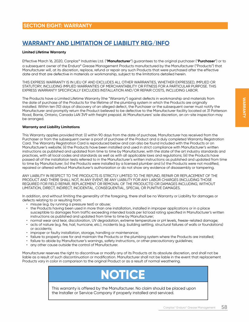
Canplas® Endura® Grease Management 58
WA
RR
AN
TY
WARRANTY AND LIMITATION OF LIABILITY REG/INFO
Limited Lifetime Warranty
Effective March 16, 2020, Canplas® Industries Ltd. (“Manufacturer”) guarantees to the original purchaser (“Purchaser”) or to
a subsequent owner of the Endura® Grease Management Products manufactured by the Manufacturer (“Products”) that Manufacturer will, at its discretion, replace, refund or repair any such Products that were purchased after the effective date and that are defective in materials or workmanship, subject to the limitations detailed herein.
THIS EXPRESS WARRANTY IS IN LIEU OF AND EXCLUDES ALL OTHER WARRANTIES, WHETHER EXPRESSED, IMPLIED OR STATUTORY, INCLUDING IMPLIED WARRANTIES OF MERCHANTABILITY OR FITNESS FOR A PARTICULAR PURPOSE. THIS EXPRESS WARRANTY SPECIFICALLY EXCLUDES INSTALLATION AND/OR REPAIR COSTS, INCLUDING LABOR.
The Products have a Limited Lifetime Warranty (the “Warranty”) against defects in workmanship and materials from the date of purchase of the Products for the lifetime of the plumbing system in which the Products are originally installed. Within ten (10) days of discovery of an alleged defect, the Purchaser or the subsequent owner must notify the Manufacturer and promptly return the Product believed to be defective to the Manufacturer facility located at 31 Patterson Road, Barrie, Ontario, Canada L4N 3V9 with freight prepaid. At Manufacturers’ sole discretion, an on-site inspection may be arranged.
Warranty and Liability Limitations
This Warranty applies provided that: (i) within 90 days from the date of purchase, Manufacturer has received from the Purchaser or from the subsequent owner a proof of purchase of the Product and a duly completed Warranty Registration Card. The Warranty Registration Card is reproduced below and can also be found included with the Products or on Manufacturer’s website; (ii) the Products have been installed and used in strict compliance with Manufacturer’s written instructions as published and updated from time to time by Manufacturer, with the state of the art industry standards and practices, with all local codes and standards as well as with all applicable laws and regulations; (iii) the Products have passed all of the installation tests referred to in the Manufacturer’s written instructions as published and updated from time to time by Manufacturer; (iv) the Products were installed by a licensed plumber and (v) the Products were not modified, repaired or altered without Manufacturer’s authorization or do not show any evidence of disassembly or tampering.
ANY LIABILITY IN RESPECT TO THE PRODUCTS IS STRICTLY LIMITED TO THE REFUND, REPAIR OR REPLACEMENT OF THE PRODUCT AND THERE SHALL NOT, IN ANY EVENT, BE ANY LIABILITY FOR ANY LABOR CHARGES (INCLUDING THOSE REQUIRED FOR FIELD REPAIR, REPLACEMENT OR REMOVAL OF THE PRODUCTS) OR DAMAGES INCLUDING, WITHOUT LIMITATION, DIRECT, INDIRECT, INCIDENTAL, CONSEQUENTIAL, SPECIAL OR PUNITIVE DAMAGES.
In addition, and without limiting the generality of the foregoing, there shall be no Warranty or Liability for damages or defects relating to or resulting from: • misuse (e.g. by running a pressure test) or abuse; • the Products having been used in more than one installation, installed in improper applications or in a place susceptible to damages from traffic exceeding intended loads per lid load rating specified in Manufacturer’s written instructions as published and updated from time to time by Manufacturer; • normal wear and tear, discoloration, UV degradation, extreme temperature or pH levels, freeze-related damage; • acts of nature (e.g. fire, hail, hurricane, etc.), incidents (e.g. building settling, structural failures of walls or foundations) or accidents; • improper or faulty installation, storage, handling or maintenance; • failure to properly care for and maintain the Products or the plumbing system where the Products are installed; • failure to abide by Manufacturer’s warnings, safety instructions, or other precautionary guidelines; • any other cause outside the control of Manufacturer.
Manufacturer reserves the right to discontinue or modify any of its Products at its absolute discretion, and shall not be liable as a result of such discontinuation or modification. Manufacturer shall not be liable in the event that replacement Products vary in color in comparison to the original Product or as a result of normal weathering.
SECTION EIGHT: WARRANTY
NOTICEThis warranty is offered by the Manufacturer. No claim should be placed upon the Installer or Service Company if properly installed and serviced.
59 Canplas® Endura® Grease Management
NOTES
____________________________________________________
____________________________________________________
____________________________________________________
____________________________________________________
____________________________________________________
____________________________________________________
____________________________________________________
____________________________________________________
____________________________________________________
____________________________________________________
___________________________________________________
____________________________________________________
____________________________________________________
____________________________________________________
____________________________________________________
___________________________________________________
____________________________________________________
____________________________________________________
____________________________________________________
___________________________________________________
____________________________________________________
____________________________________________________
____________________________________________________
___________________________________________________
____________________________________________________
____________________________________________________
____________________________________________________
____________________________________________________
____________________________________________________
____________________________________________________
____________________________________________________
____________________________________________________
____________________________________________________
_________________________________________________
Canplas® Endura® Grease Management 60
NOTES
____________________________________________________
____________________________________________________
____________________________________________________
____________________________________________________
____________________________________________________
____________________________________________________
____________________________________________________
____________________________________________________
____________________________________________________
____________________________________________________
___________________________________________________
____________________________________________________
____________________________________________________
____________________________________________________
____________________________________________________
___________________________________________________
____________________________________________________
____________________________________________________
____________________________________________________
___________________________________________________
____________________________________________________
____________________________________________________
____________________________________________________
___________________________________________________
____________________________________________________
____________________________________________________
____________________________________________________
____________________________________________________
____________________________________________________
____________________________________________________
____________________________________________________
____________________________________________________
____________________________________________________
_________________________________________________
61 Canplas® Endura® Grease Management
®
www.arcat.com www.csc-dcc.ca www.csinet.org
Technical Support
EnduraInterceptor.com
Endura® Grease Interceptors are manufactured
in a ISO 9001 and 14001 registered facility. Our
quality management system has been registered
for the design, manufacture and distribution of
high quality injection molded products used
in plumbing, industrial, ventilation and central
vacuum applications.
See our course online at:
Tel: (705) 726-3361
1-800-461-1771Fax: (705) 726-2186
Canplas Industries Ltd.Separation Technologies Group500 Veterans Drive, PO Box 1800Barrie, ON L4M 4V3 Canada