Embed Size (px)
Citation preview
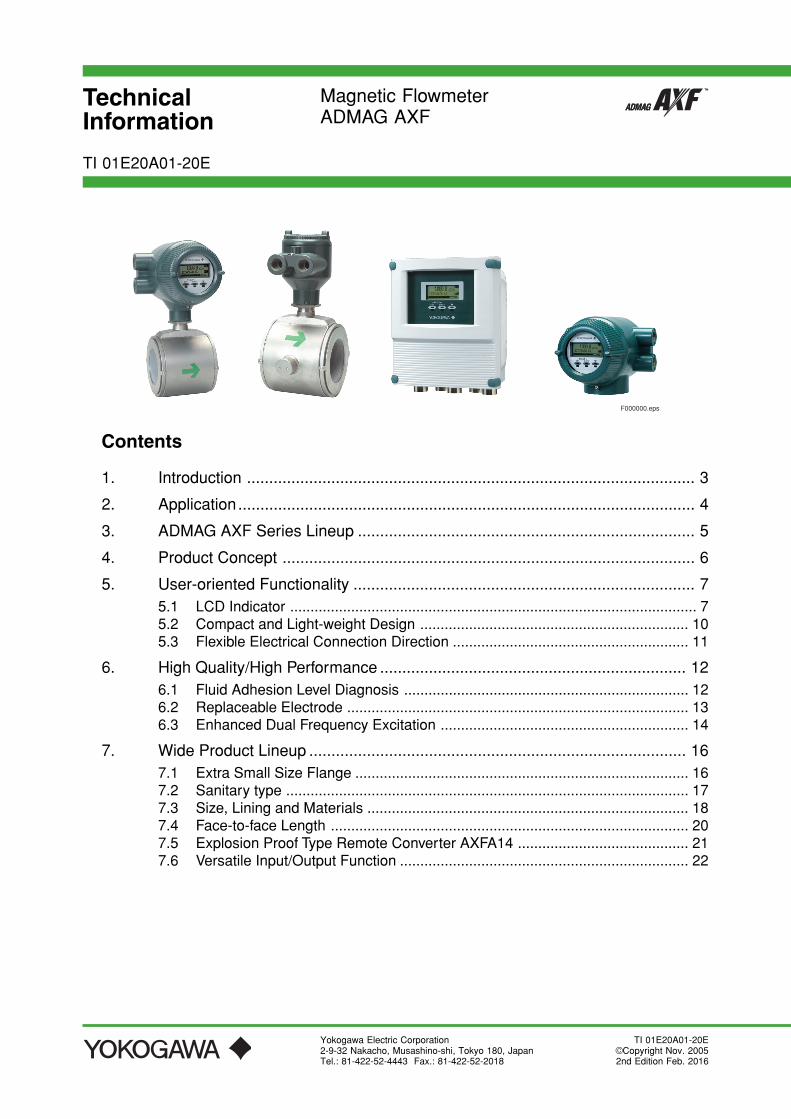
TechnicalInformation
Magnetic FlowmeterADMAG AXF
Yokogawa Electric Corporation2-9-32 Nakacho, Musashino-shi, Tokyo 180, JapanTel.: 81-422-52-4443 Fax.: 81-422-52-2018
TI 01E20A01-20E
TI 01E20A01-20E ©Copyright Nov. 20052nd Edition Feb. 2016
Contents
1. Introduction ..................................................................................................... 3
2. Application....................................................................................................... 4
3. ADMAG AXF Series Lineup ............................................................................ 5
4. Product Concept ............................................................................................. 6
5. User-oriented Functionality ............................................................................. 75.1 LCD Indicator .................................................................................................... 75.2 Compact and Light-weight Design .................................................................. 105.3 Flexible Electrical Connection Direction .......................................................... 11
6. High Quality/High Performance ..................................................................... 126.1 Fluid Adhesion Level Diagnosis ...................................................................... 126.2 Replaceable Electrode .................................................................................... 136.3 Enhanced Dual Frequency Excitation ............................................................. 14
7. Wide Product Lineup ..................................................................................... 167.1 Extra Small Size Flange .................................................................................. 167.2 Sanitary type ................................................................................................... 177.3 Size, Lining and Materials ............................................................................... 187.4 Face-to-face Length ........................................................................................ 207.5 Explosion Proof Type Remote Converter AXFA14 .......................................... 217.6 Versatile Input/Output Function ....................................................................... 22
F000000.eps
All Rights Reserved. Copyright © 2005, Yokogawa Electric Corporation TI 01E20A01-20E
3<Toc> <Ind>
2016.02.29-00
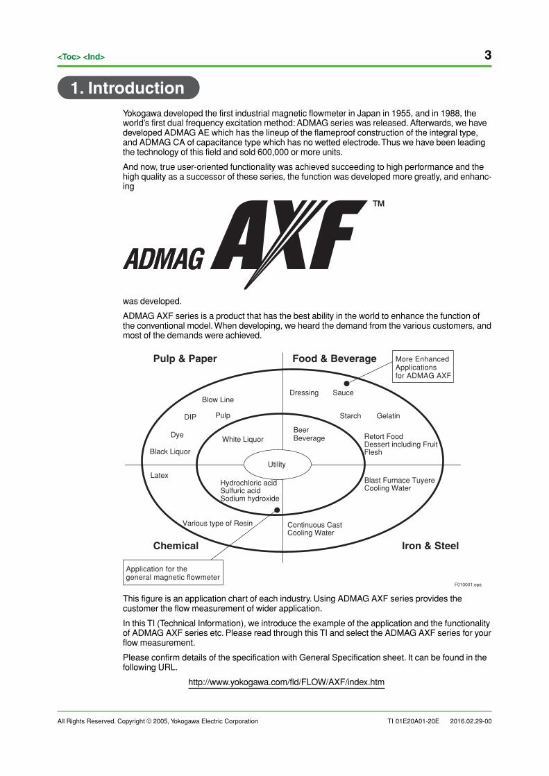
1. IntroductionYokogawa developed the first industrial magnetic flowmeter in Japan in 1955, and in 1988, theworld’s first dual frequency excitation method: ADMAG series was released. Afterwards, we havedeveloped ADMAG AE which has the lineup of the flameproof construction of the integral type,and ADMAG CA of capacitance type which has no wetted electrode. Thus we have been leadingthe technology of this field and sold 600,000 or more units.
And now, true user-oriented functionality was achieved succeeding to high performance and thehigh quality as a successor of these series, the function was developed more greatly, and enhanc-ing
was developed.
ADMAG AXF series is a product that has the best ability in the world to enhance the function ofthe conventional model. When developing, we heard the demand from the various customers, andmost of the demands were achieved.
F010001.eps
Pulp & Paper
Chemical Iron & Steel
Food & Beverage
Pulp
White LiquorBeerBeverage
Blast Furnace Tuyere Cooling Water
Latex
Dressing Sauce
Starch Gelatin
Retort FoodDessert including Fruit Flesh
Blow Line
DIP
Black Liquor
Various type of Resin Continuous Cast Cooling Water
Dye
More Enhanced Applicationsfor ADMAG AXF
Utility
Application for thegeneral magnetic flowmeter
Hydrochloric acidSulfuric acidSodium hydroxide
This figure is an application chart of each industry. Using ADMAG AXF series provides thecustomer the flow measurement of wider application.
In this TI (Technical Information), we introduce the example of the application and the functionalityof ADMAG AXF series etc. Please read through this TI and select the ADMAG AXF series for yourflow measurement.
Please confirm details of the specification with General Specification sheet. It can be found in thefollowing URL.
http://www.yokogawa.com/fld/FLOW/AXF/index.htm
4
All Rights Reserved. Copyright © 2005, Yokogawa Electric Corporation
<Toc> <Ind>
TI 01E20A01-20E 2016.02.29-00
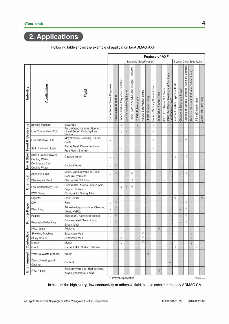
2. ApplicationsFollowing table shows the example of application for ADMAG AXF.
√ √
√
√
√
√
√
√
√
√
√
√
√
√
√
√
√
√
√
√
√
√
√
√
√
√
√
√
√
√
√
√
√
√
√
√
√
√
√
√
√
√
√
√√√
√√√
√√√
√
√
√ √
√
√
√
√
√
Ap
plic
atio
n
Flu
id
Feature of AXFStandard Specification Special Order Spacification
Iron
& St
eel
Food
& B
ever
age
Ind
ust
ryC
hem
ical
Pu
lp &
Pap
erCo
nstru
ctio
nE
nvi
ron
men
t
Bottling Machine
Low Conductivity Fluid
Oily Adhesive Fluid
Solid included Liquid
Blast Furnace Tuyere
Cooling Water
Continuous Cast
Cooling Water
Adhesive Fluid
Electrolysis Plant
Low Conductivity Fluid
PVC Piping
DIP
Bleaching
Digester
Pulping
Recovery Boiler Line
PVC Piping
Shielding Machine
District Heating and
Cooling
PVC Piping
Slurry Shield
Mortar
Grout
Water & Waste process
Pure Water, Vinegar, Alcohol, Liquid Suger, Carbohydrate SolutionMayonnaise, Dressing, Sauce,
Baste
Retort Food, Desser including
Fruit Flesh, Sherbet
Coolant Water
Coolant Water
Latex, Various types of Resin,
Sodium Hydroxide
Electrolysis Solution
Pure Water, Alcohol, Acetic Acid,
Organic Solvent
Strong Acid, Strong Alkali
Black Liquor
Pulp
Adhesive Liquid such as Chlorine,
Alkali, HYPO.
Size agent, Aluminum Sulfate
Concentrated Black Liquor,
Green liquor
Additive,
Excavated Mud
Excavated Mud
Mortar
Cement Milk, Sodium Silicate
Water
Coolant
Sodium Hydroxide, Hydrochloric
Acid, Hypochlorous Acid
Flu
id A
dhes
ion
Leve
l Dia
gnos
is
Rep
lace
able
Ele
ctro
de
Enh
ance
d du
al fr
eque
ncy
Exc
itatio
n
Low
Con
duct
ivity
(1µS
/cm
)
Fla
me
Pro
of (
AX
FA
14, A
XF
Inte
gral
, Rem
ote)
10 K
Hz
Pul
se o
utpu
t
Nat
ural
Sof
t Rub
ber
Lini
ng
EP
DM
Rub
ber
Lini
ng
Var
ious
San
itary
Con
nect
ions
Ext
ra S
mal
l Fla
nge
Typ
e
/ELC
:FD
C N
oise
Cut
Circ
uit
/DH
C :F
or D
istr
ict H
eatin
g an
d C
oolin
g or
C
onde
nsat
ion-
proo
f
Inte
rnal
Inse
rtio
n T
ype
Ele
ctro
de
Cha
nge
of E
lect
rode
Sha
pe
Cha
nge
of S
urfa
ce F
inis
hing
(Li
ning
/Ele
ctro
de)
Abr
asio
n R
esis
tant
Ure
than
e R
ubbe
r Li
ning
JIS
63K
Waf
er M
eter
Met
al H
at E
arth
Rin
g
Beverage
√: Proven Application T020001.eps
In case of the high slurry, low conductivity or adhesive fluid, please consider to apply ADMAG CA.
All Rights Reserved. Copyright © 2005, Yokogawa Electric Corporation TI 01E20A01-20E
5<Toc> <Ind>
2016.02.29-00
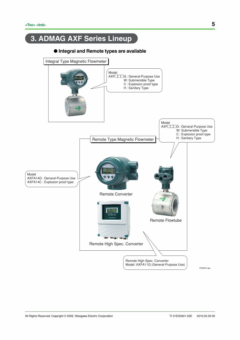
3. ADMAG AXF Series Lineup
● Integral and Remote types are available
F030001.eps
Integral Type Magnetic Flowmeter
ModelAXF���G : General-Purpose Use W : Submersible Type C : Explosion proof type H : Sanitary Type
Remote Type Magnetic Flowmeter
Remote Converter
Remote Flowtube
Remote High Spec. Converter
ModelAXFA14G : Genaral-Purpose UseAXFA14C : Explosion proof type
ModelAXF���G : Genaral-Purpose Use W : Submersible Type C : Explosion proof type H : Sanitary Type
Remote High Spec. ConverterModel: AXFA11G (General-Purpose Use)
6
All Rights Reserved. Copyright © 2005, Yokogawa Electric Corporation
<Toc> <Ind>
TI 01E20A01-20E 2016.02.29-00
F040001.eps
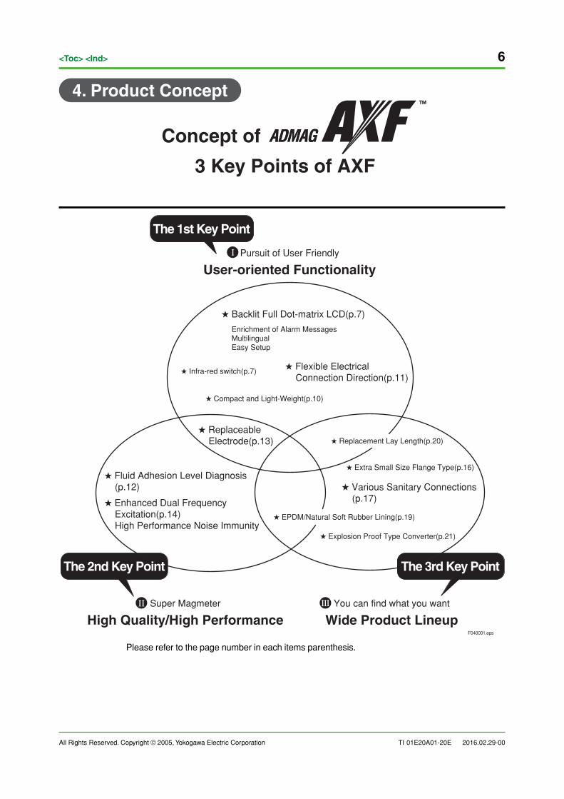
Concept of
3 Key Points of AXF
� Replaceable Electrode(p.13)
The 1st Key Point
The 2nd Key Point The 3rd Key Point
� Replacement Lay Length(p.20)
� Backlit Full Dot-matrix LCD(p.7)
Enrichment of Alarm MessagesMultilingualEasy Setup
� Flexible Electrical Connection Direction(p.11)
� Compact and Light-Weight(p.10)
� Infra-red switch(p.7)
� Various Sanitary Connections (p.17)
� Explosion Proof Type Converter(p.21)
� EPDM/Natural Soft Rubber Lining(p.19)
� Extra Small Size Flange Type(p.16)
� Enhanced Dual Frequency Excitation(p.14) High Performance Noise Immunity
� Fluid Adhesion Level Diagnosis (p.12)
Pursuit of User Friendly
User-oriented Functionality
Super Magmeter
High Quality/High PerformanceYou can find what you want
Wide Product Lineup
I
II III
Please refer to the page number in each items parenthesis.
4. Product Concept
All Rights Reserved. Copyright © 2005, Yokogawa Electric Corporation TI 01E20A01-20E
7<Toc> <Ind>
2016.02.29-00
5. User-oriented Functionality
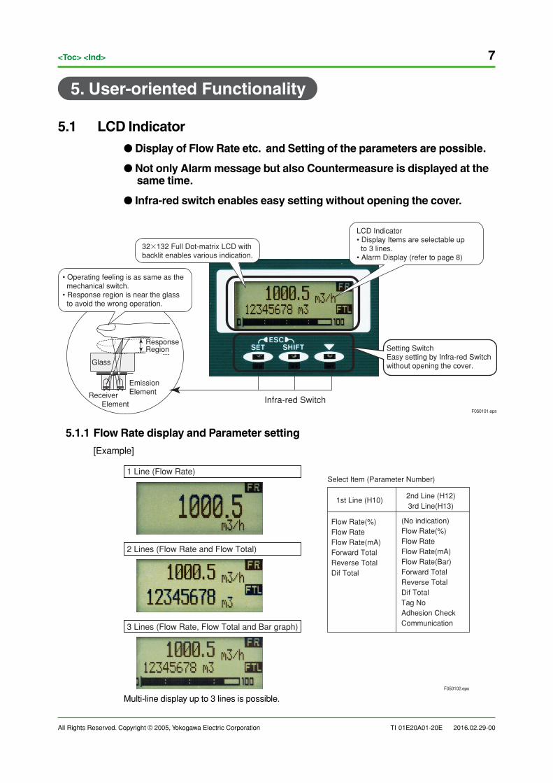
5.1 LCD Indicator
● Display of Flow Rate etc. and Setting of the parameters are possible.
● Not only Alarm message but also Countermeasure is displayed at thesame time.
● Infra-red switch enables easy setting without opening the cover.
F050101.eps
Receiver Element
EmissionElement
ResponseRegion
Glass
• Operating feeling is as same as the mechanical switch.• Response region is near the glass to avoid the wrong operation.
32�132 Full Dot-matrix LCD withbacklit enables various indication.
LCD Indicator• Display Items are selectable up to 3 lines.• Alarm Display (refer to page 8)
Setting SwitchEasy setting by Infra-red Switchwithout opening the cover.
Infra-red Switch
5.1.1 Flow Rate display and Parameter setting
[Example]
1st Line (H10)
Flow Rate(%)Flow RateFlow Rate(mA)Forward TotalReverse TotalDif Total
2nd Line (H12)3rd Line(H13)
Select Item (Parameter Number)
(No indication)Flow Rate(%)Flow RateFlow Rate(mA)Flow Rate(Bar)Forward TotalReverse TotalDif TotalTag NoAdhesion CheckCommunication
1 Line (Flow Rate)
2 Lines (Flow Rate and Flow Total)
3 Lines (Flow Rate, Flow Total and Bar graph)
F050102.eps
Multi-line display up to 3 lines is possible.
8
All Rights Reserved. Copyright © 2005, Yokogawa Electric Corporation
<Toc> <Ind>
TI 01E20A01-20E 2016.02.29-00
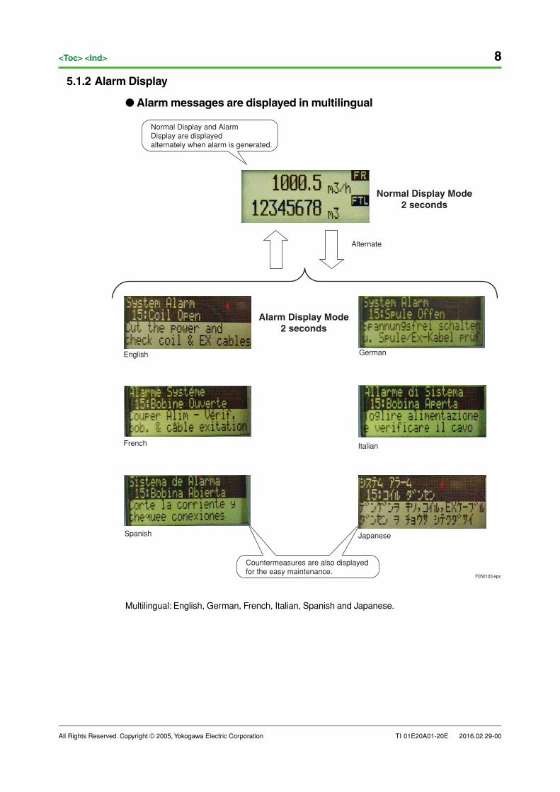
5.1.2 Alarm Display
● Alarm messages are displayed in multilingual
F050103.eps
Normal Display and AlarmDisplay are displayedalternately when alarm is generated.
Normal Display Mode2 seconds
Alternate
Alarm Display Mode2 seconds
Countermeasures are also displayed for the easy maintenance.
English
Japanese
French
German
Italian
Spanish
Multilingual: English, German, French, Italian, Spanish and Japanese.
All Rights Reserved. Copyright © 2005, Yokogawa Electric Corporation TI 01E20A01-20E
9<Toc> <Ind>
2016.02.29-00
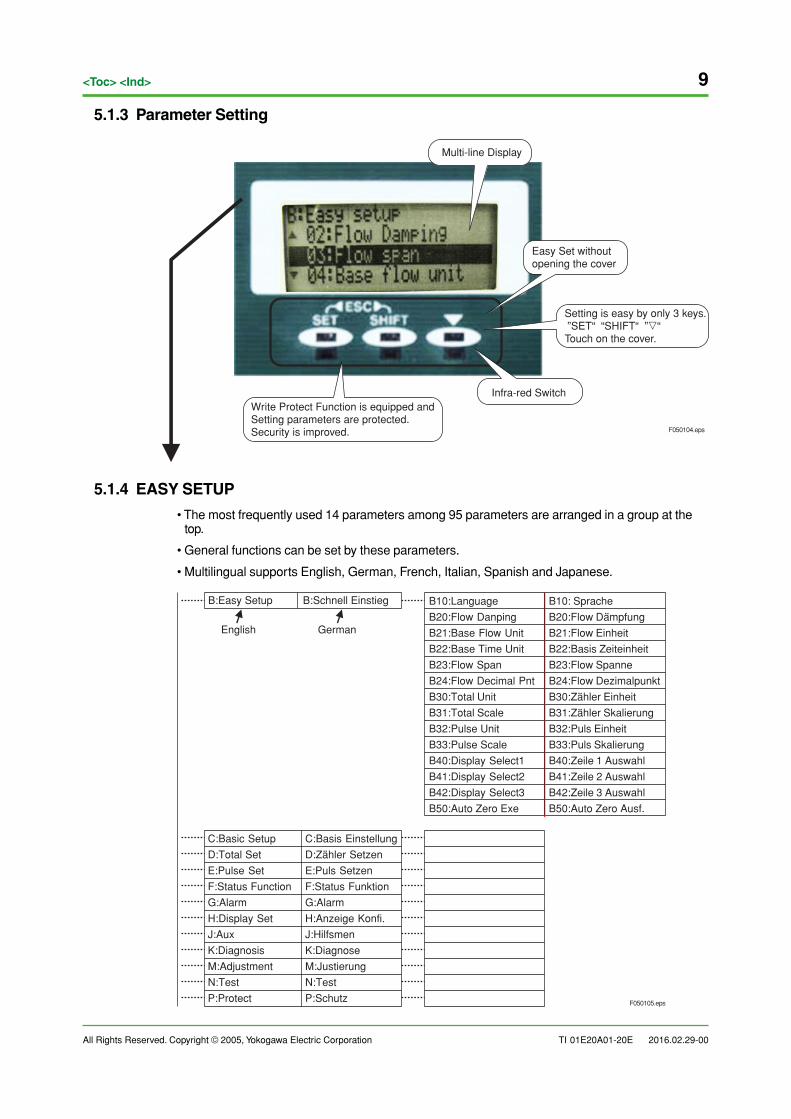
5.1.3 Parameter Setting
Infra-red Switch
Multi-line Display
Easy Set withoutopening the cover
F050104.eps
Write Protect Function is equipped andSetting parameters are protected.Security is improved.
Setting is easy by only 3 keys. ”SET“ “SHIFT“ ”�“Touch on the cover.
5.1.4 EASY SETUP
• The most frequently used 14 parameters among 95 parameters are arranged in a group at thetop.
• General functions can be set by these parameters.
• Multilingual supports English, German, French, Italian, Spanish and Japanese.
F050105.eps
English German
B:Schnell EinstiegB:Easy Setup
C:Basic Setup
D:Total Set
E:Pulse Set
F:Status Function
G:Alarm
H:Display Set
J:Aux
K:Diagnosis
M:Adjustment
N:Test
P:Protect
B10: Sprache
B20:Flow Dampfung
B21:Flow Einheit
B22:Basis Zeiteinheit
B23:Flow Spanne
B24:Flow Dezimalpunkt
B30:Zahler Einheit
B31:Zahler Skalierung
B32:Puls Einheit
B33:Puls Skalierung
B40:Zeile 1 Auswahl
B41:Zeile 2 Auswahl
B42:Zeile 3 Auswahl
B50:Auto Zero Ausf.
B10:Language
B20:Flow Danping
B21:Base Flow Unit
B22:Base Time Unit
B23:Flow Span
B24:Flow Decimal Pnt
B30:Total Unit
B31:Total Scale
B32:Pulse Unit
B33:Pulse Scale
B40:Display Select1
B41:Display Select2
B42:Display Select3
B50:Auto Zero Exe
C:Basis Einstellung
D:Zahler Setzen
E:Puls Setzen
F:Status Funktion
G:Alarm
H:Anzeige Konfi.
J:Hilfsmen
K:Diagnose
M:Justierung
N:Test
P:Schutz
10
All Rights Reserved. Copyright © 2005, Yokogawa Electric Corporation
<Toc> <Ind>
TI 01E20A01-20E 2016.02.29-00
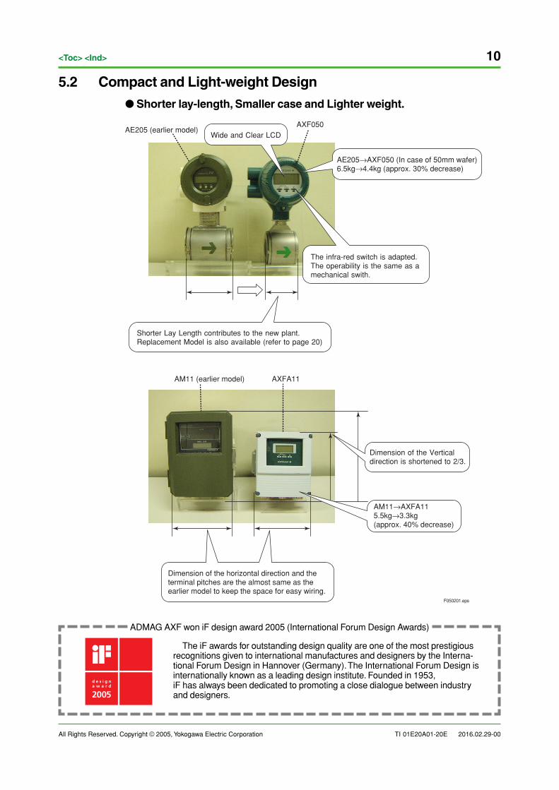
5.2 Compact and Light-weight Design
● Shorter lay-length, Smaller case and Lighter weight.
F050201.eps
Shorter Lay Length contributes to the new plant.Replacement Model is also available (refer to page 20)
Dimension of the horizontal direction and theterminal pitches are the almost same as theearlier model to keep the space for easy wiring.
AM11→AXFA115.5kg→3.3kg(approx. 40% decrease)
AE205→AXF050 (In case of 50mm wafer)6.5kg→4.4kg (approx. 30% decrease)
Wide and Clear LCDAE205 (earlier model)
AXF050
AM11 (earlier model)
Dimension of the Verticaldirection is shortened to 2/3.
The infra-red switch is adapted.The operability is the same as amechanical swith.
AXFA11
ADMAG AXF won iF design award 2005 (International Forum Design Awards)
The iF awards for outstanding design quality are one of the most prestigiousrecognitions given to international manufactures and designers by the Interna-tional Forum Design in Hannover (Germany). The International Forum Design isinternationally known as a leading design institute. Founded in 1953,iF has always been dedicated to promoting a close dialogue between industryand designers.
All Rights Reserved. Copyright © 2005, Yokogawa Electric Corporation TI 01E20A01-20E
11<Toc> <Ind>
2016.02.29-00
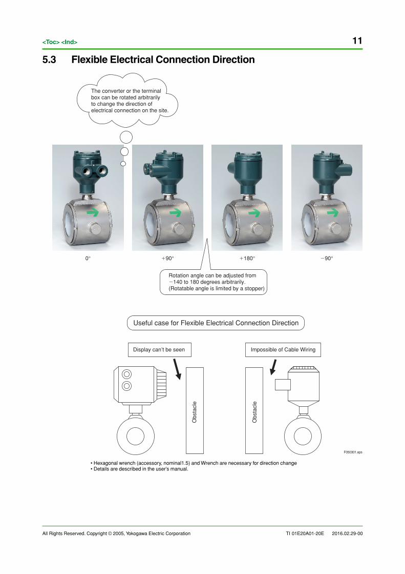
5.3 Flexible Electrical Connection Direction
0° �180°�90° �90°
Impossible of Cable Wiring
Useful case for Flexible Electrical Connection Direction
Display can’t be seen
Obs
tacl
e
Obs
tacl
e
The converter or the terminalbox can be rotated arbitrarilyto change the direction ofelectrical connection on the site.
Rotation angle can be adjusted from �140 to 180 degrees arbitrarily.(Rotatable angle is limited by a stopper)
F050301.eps
• Hexagonal wrench (accessory, nominal1.5) and Wrench are necessary for direction change• Details are described in the user’s manual.
12
All Rights Reserved. Copyright © 2005, Yokogawa Electric Corporation
<Toc> <Ind>
TI 01E20A01-20E 2016.02.29-00
6. High Quality / High Performance
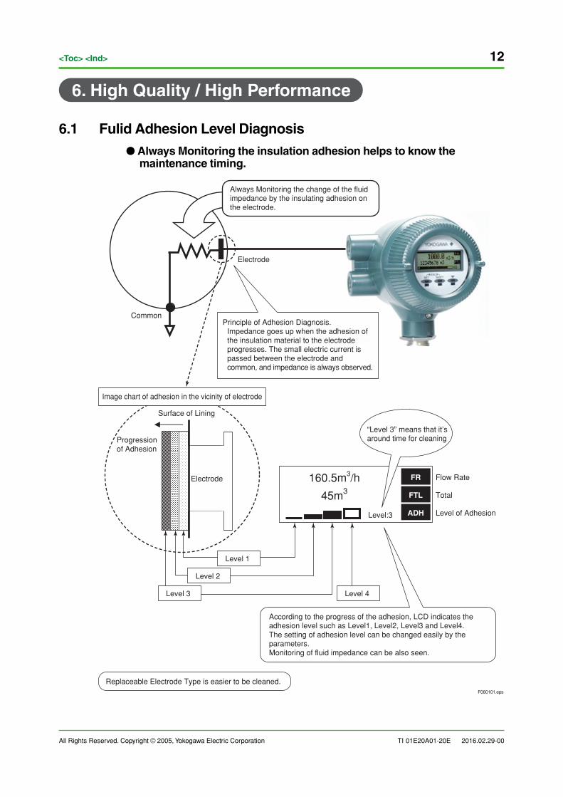
6.1 Fulid Adhesion Level Diagnosis
● Always Monitoring the insulation adhesion helps to know themaintenance timing.
F060101.eps
Electrode
Level of Adhesion
Flow Rate160.5m3/h
45m3
FR
FTL
Level:3 ADH
Total
Level 2
Level 1
Level 3 Level 4
Image chart of adhesion in the vicinity of electrode
Surface of Lining
Progressionof Adhesion
Common
Always Monitoring the change of the fluidimpedance by the insulating adhesion onthe electrode.
“Level 3” means that it’s around time for cleaning
Replaceable Electrode Type is easier to be cleaned.
Electrode
Principle of Adhesion Diagnosis. Impedance goes up when the adhesion of the insulation material to the electrode progresses. The small electric current is passed between the electrode and common, and impedance is always observed.
According to the progress of the adhesion, LCD indicates the adhesion level such as Level1, Level2, Level3 and Level4.The setting of adhesion level can be changed easily by the parameters.Monitoring of fluid impedance can be also seen.
All Rights Reserved. Copyright © 2005, Yokogawa Electric Corporation TI 01E20A01-20E
13<Toc> <Ind>
2016.02.29-00
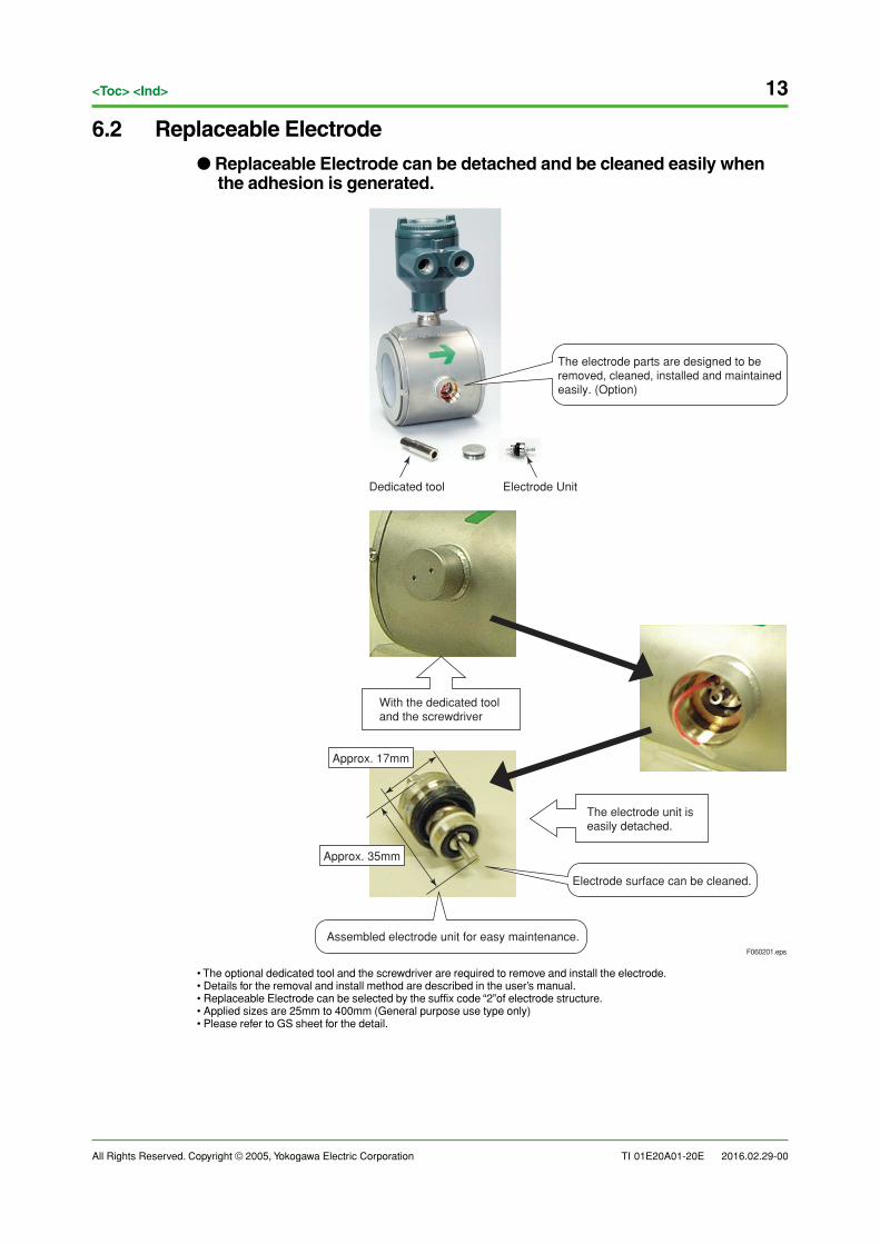
6.2 Replaceable Electrode
● Replaceable Electrode can be detached and be cleaned easily whenthe adhesion is generated.
F060201.eps
Dedicated tool Electrode Unit
With the dedicated tooland the screwdriver
The electrode unit iseasily detached.
Approx. 35mm
Approx. 17mm
Assembled electrode unit for easy maintenance.
Electrode surface can be cleaned.
The electrode parts are designed to be removed, cleaned, installed and maintained easily. (Option)
• The optional dedicated tool and the screwdriver are required to remove and install the electrode.• Details for the removal and install method are described in the user’s manual.• Replaceable Electrode can be selected by the suffix code “2”of electrode structure.• Applied sizes are 25mm to 400mm (General purpose use type only)• Please refer to GS sheet for the detail.
14
All Rights Reserved. Copyright © 2005, Yokogawa Electric Corporation
<Toc> <Ind>
TI 01E20A01-20E 2016.02.29-00
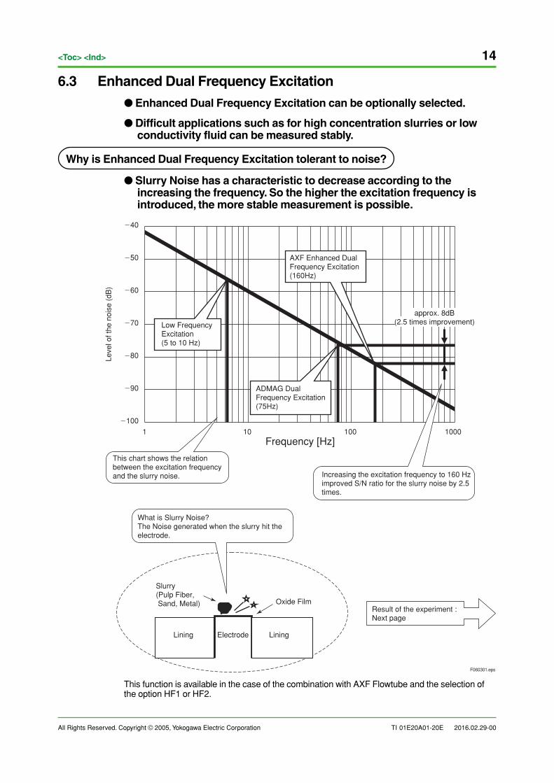
6.3 Enhanced Dual Frequency Excitation
● Enhanced Dual Frequency Excitation can be optionally selected.
● Difficult applications such as for high concentration slurries or lowconductivity fluid can be measured stably.
Why is Enhanced Dual Frequency Excitation tolerant to noise?
● Slurry Noise has a characteristic to decrease according to theincreasing the frequency. So the higher the excitation frequency isintroduced, the more stable measurement is possible.
Leve
l of t
he n
oise
(dB
)
Frequency [Hz]
Slurry(Pulp Fiber, Sand, Metal)
Result of the experiment :Next page
AXF Enhanced DualFrequency Excitation(160Hz)
Low FrequencyExcitation(5 to 10 Hz)
approx. 8dB(2.5 times improvement)
Increasing the excitation frequency to 160 Hz improved S/N ratio for the slurry noise by 2.5 times.
F060301.eps
ADMAG DualFrequency Excitation(75Hz)
Electrode
Oxide Film
Lining Lining
�100
�90
�80
�70
�60
�50
�40
1 10 100 1000
This chart shows the relation between the excitation frequency and the slurry noise.
What is Slurry Noise?The Noise generated when the slurry hit the electrode.
This function is available in the case of the combination with AXF Flowtube and the selection ofthe option HF1 or HF2.
All Rights Reserved. Copyright © 2005, Yokogawa Electric Corporation TI 01E20A01-20E
15<Toc> <Ind>
2016.02.29-00
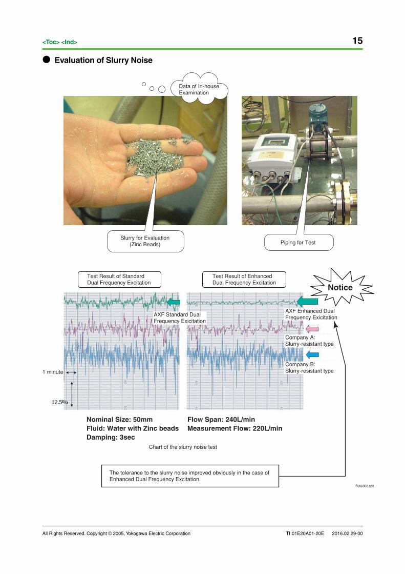
● Evaluation of Slurry Noise
F060302.eps
Chart of the slurry noise test
The tolerance to the slurry noise improved obviously in the case ofEnhanced Dual Frequency Excitation.
Test Result of EnhancedDual Frequency Excitation
Test Result of StandardDual Frequency Excitation
Notice
Slurry for Evaluation(Zinc Beads) Piping for Test
Data of In-houseExamination
Nominal Size: 50mmFluid: Water with Zinc beadsDamping: 3sec
Flow Span: 240L/minMeasurement Flow: 220L/min
AXF Standard DualFrequency Exicitation
1 minute
Company A:Slurry-resistant type
Company B:Slurry-resistant type
AXF Enhanced Dual Frequency Exicitation
16
All Rights Reserved. Copyright © 2005, Yokogawa Electric Corporation
<Toc> <Ind>
TI 01E20A01-20E 2016.02.29-00
7. Wide Product Lineup
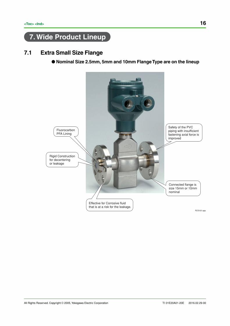
7.1 Extra Small Size Flange
● Nominal Size 2.5mm, 5mm and 10mm Flange Type are on the lineup
FluorocarbonPFA Lining
Rigid Constructionfor decenteringor leakage
F070101.eps
Connected flange issize 15mm or 10mm nominal
Effective for Corrosive fluidthat is at a risk for the leakage.
Safety of the PVCpiping with insufficient fastening axial force is improved
All Rights Reserved. Copyright © 2005, Yokogawa Electric Corporation TI 01E20A01-20E
17<Toc> <Ind>
2016.02.29-00
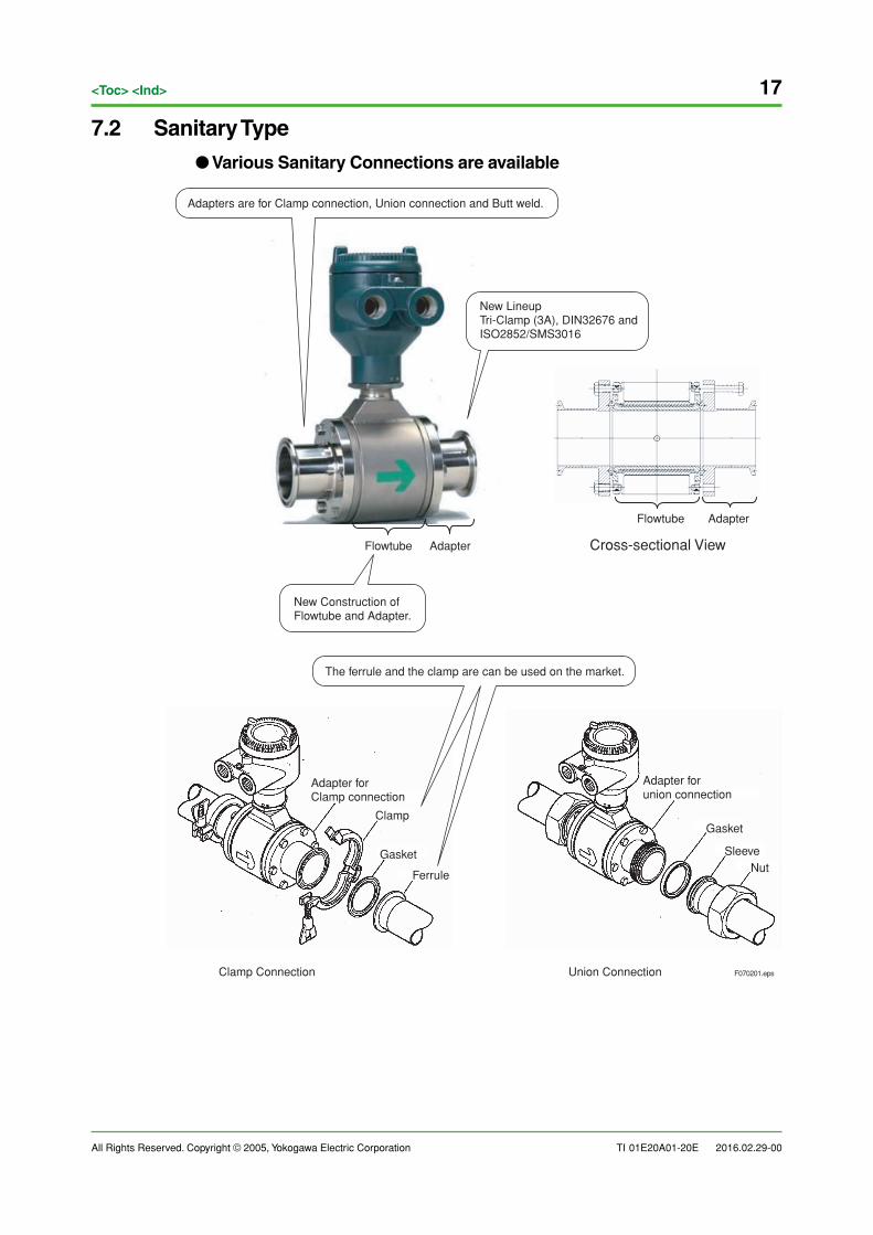
7.2 Sanitary Type
● Various Sanitary Connections are available
F070201.eps
Flowtube Adapter
Flowtube
Cross-sectional View
Adapter
The ferrule and the clamp are can be used on the market.
New Construction ofFlowtube and Adapter.
Adapters are for Clamp connection, Union connection and Butt weld.
Clamp Connection Union Connection
Adapter forClamp connection
Clamp
Gasket
Ferrule
Adapter forunion connection
Sleeve
Gasket
Nut
New LineupTri-Clamp (3A), DIN32676 and ISO2852/SMS3016
18
All Rights Reserved. Copyright © 2005, Yokogawa Electric Corporation
<Toc> <Ind>
TI 01E20A01-20E 2016.02.29-00
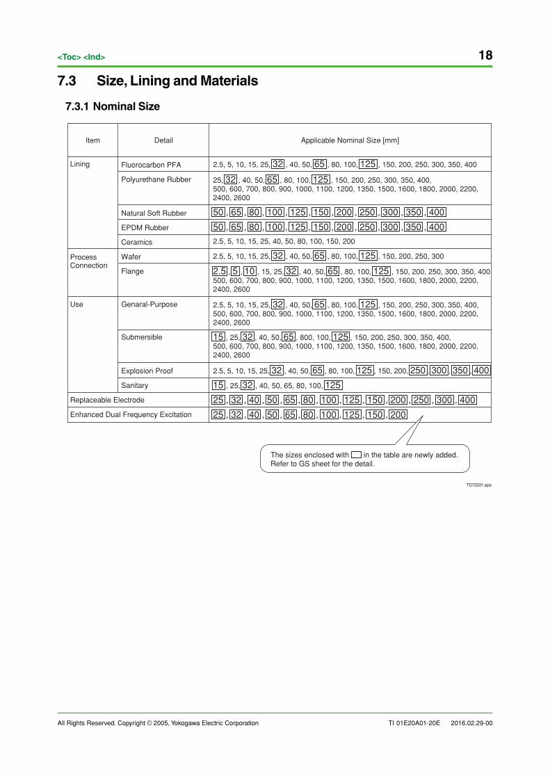
7.3 Size, Lining and Materials
7.3.1 Nominal Size
2.5, 5, 10, 15, 25, 32 , 40, 50, 65 , 80, 100, 125 , 150, 200, 250, 300, 350, 400
25, 32 , 40, 50, 65 , 80, 100, 125 , 150, 200, 250, 300, 350, 400, 500, 600, 700, 800, 900, 1000, 1100, 1200, 1350, 1500, 1600, 1800, 2000, 2200,2400, 2600
50 , 65 , 80 , 100 , 125 , 150 , 200 , 250 , 300 , 350 , 400
50 , 65 , 80 , 100 , 125 , 150 , 200 , 250 , 300 , 350 , 400
2.5, 5, 10, 15, 25, 40, 50, 80, 100, 150, 200
2.5, 5, 10, 15, 25, 32 , 40, 50, 65 , 80, 100, 125 , 150, 200, 250, 300
2.5 , 5 , 10 , 15, 25, 32 , 40, 50, 65 , 80, 100, 125 , 150, 200, 250, 300, 350, 400500, 600, 700, 800, 900, 1000, 1100, 1200, 1350, 1500, 1600, 1800, 2000, 2200,2400, 2600
2.5, 5, 10, 15, 25, 32 , 40, 50, 65 , 80, 100, 125 , 150, 200, 250, 300, 350, 400, 500, 600, 700, 800, 900, 1000, 1100, 1200, 1350, 1500, 1600, 1800, 2000, 2200, 2400, 2600
15 , 25, 32 , 40, 50, 65 , 800, 100, 125 , 150, 200, 250, 300, 350, 400,500, 600, 700, 800, 900, 1000, 1100, 1200, 1350, 1500, 1600, 1800, 2000, 2200,2400, 2600
2.5, 5, 10, 15, 25, 32 , 40, 50, 65 , 80, 100, 125 , 150, 200, 250 , 300 , 350 , 400
15 , 25, 32 , 40, 50, 65, 80, 100, 125
25 , 32 , 40 , 50 , 65 , 80 , 100 , 125 , 150 , 200 , 250 , 300 , 400
25 , 32 , 40 , 50 , 65 , 80 , 100 , 125 , 150 , 200
T070301.eps
The sizes enclosed with in the table are newly added.Refer to GS sheet for the detail.
Item
Lining
Process Connection
Use
Replaceable Electrode
Enhanced Dual Frequency Excitation
Detail Applicable Nominal Size [mm]
Fluorocarbon PFA
Polyurethane Rubber
Natural Soft Rubber
EPDM Rubber
Ceramics
Wafer
Flange
Genaral-Purpose
Submersible
Explosion Proof
Sanitary
All Rights Reserved. Copyright © 2005, Yokogawa Electric Corporation TI 01E20A01-20E
19<Toc> <Ind>
2016.02.29-00
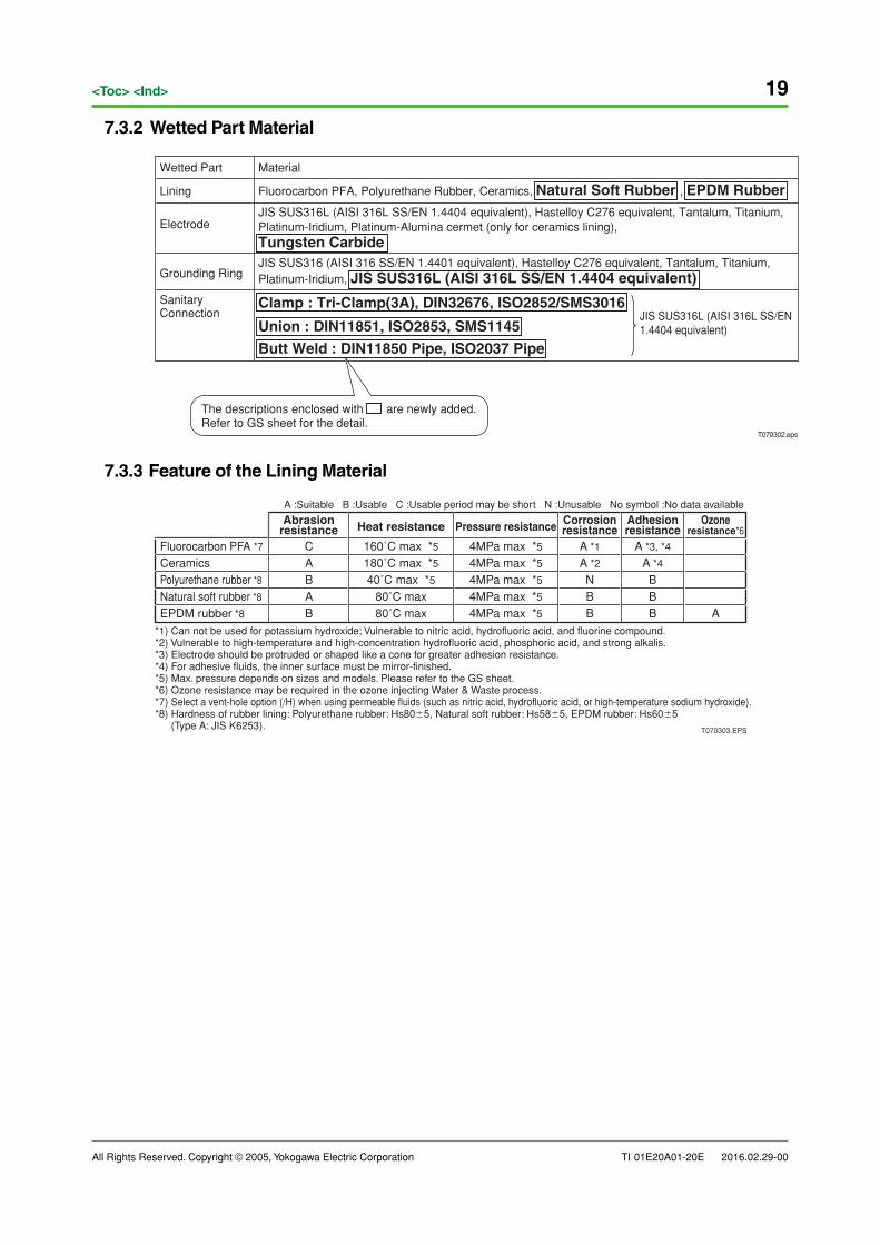
7.3.2 Wetted Part Material
T070302.eps
The descriptions enclosed with are newly added.Refer to GS sheet for the detail.
Wetted Part
Lining
Electrode
Grounding Ring
Sanitary Connection
Material
Fluorocarbon PFA, Polyurethane Rubber, Ceramics, Natural Soft Rubber , EPDM RubberJIS SUS316L (AISI 316L SS/EN 1.4404 equivalent), Hastelloy C276 equivalent, Tantalum, Titanium, Platinum-Iridium, Platinum-Alumina cermet (only for ceramics lining), Tungsten CarbideJIS SUS316 (AISI 316 SS/EN 1.4401 equivalent), Hastelloy C276 equivalent, Tantalum, Titanium, Platinum-Iridium, JIS SUS316L (AISI 316L SS/EN 1.4404 equivalent)
Clamp : Tri-Clamp(3A), DIN32676, ISO2852/SMS3016
Union : DIN11851, ISO2853, SMS1145
Butt Weld : DIN11850 Pipe, ISO2037 Pipe
JIS SUS316L (AISI 316L SS/EN1.4404 equivalent)
7.3.3 Feature of the Lining Material
80˚C max 4MPa max *5
A *4
A *3, *4
180˚C max *5
40˚C max *5 4MPa max *5
4MPa max *5 A *2
160˚C max *5 4MPa max *5 A *1
4MPa max *580˚C maxA
AB
C
BBN
BBB
B AEPDM rubber *8Natural soft rubber *8
Heat resistance Ozoneresistance*6Pressure resistance Corrosion
resistanceAdhesionresistance
Fluorocarbon PFA *7CeramicsPolyurethane rubber *8
Abrasionresistance
A :Suitable B :Usable C :Usable period may be short N :Unusable No symbol :No data available
T070303.EPS
*1) Can not be used for potassium hydroxide; Vulnerable to nitric acid, hydrofluoric acid, and fluorine compound.*2) Vulnerable to high-temperature and high-concentration hydrofluoric acid, phosphoric acid, and strong alkalis.*3) Electrode should be protruded or shaped like a cone for greater adhesion resistance.*4) For adhesive fluids, the inner surface must be mirror-finished.*5) Max. pressure depends on sizes and models. Please refer to the GS sheet.*6) Ozone resistance may be required in the ozone injecting Water & Waste process.*7) Select a vent-hole option (/H) when using permeable fluids (such as nitric acid, hydrofluoric acid, or high-temperature sodium hydroxide).*8) Hardness of rubber lining: Polyurethane rubber: Hs80�5, Natural soft rubber: Hs58�5, EPDM rubber: Hs60�5 (Type A: JIS K6253).
20
All Rights Reserved. Copyright © 2005, Yokogawa Electric Corporation
<Toc> <Ind>
TI 01E20A01-20E 2016.02.29-00
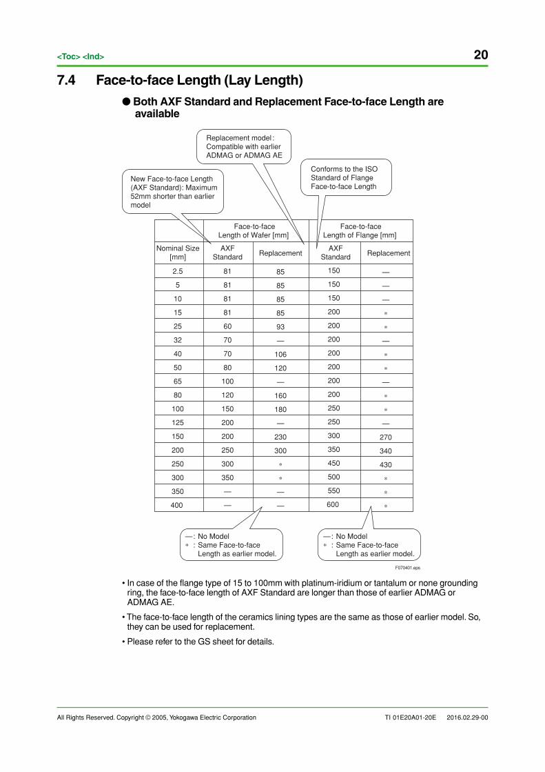
7.4 Face-to-face Length (Lay Length)
● Both AXF Standard and Replacement Face-to-face Length areavailable
Face-to-faceLength of Wafer [mm]
Face-to-faceLength of Flange [mm]
Nominal Size[mm]
AXFStandard
—
—
—
∗
∗
—
∗
∗
—
∗
∗
—
270
340
430
∗
∗
∗
ReplacementAXF
Standard Replacement
2.5
5
10
15
25
32
40
50
65
80
100
125
150
200
250
300
350
400
81
81
81
81
60
70
70
80
100
120
150
200
200
250
300
350
—
—
85
85
85
85
93
—
106
120
—
160
180
—
230
300
∗
∗
—
—
150
150
150
200
200
200
200
200
200
200
250
250
300
350
450
500
550
600
— : No Model∗ : Same Face-to-face Length as earlier model.
— : No Model∗ : Same Face-to-face Length as earlier model.
F070401.eps
New Face-to-face Length (AXF Standard): Maximum 52mm shorter than earlier model
Replacement model :Compatible with earlier ADMAG or ADMAG AE
Conforms to the ISOStandard of Flange Face-to-face Length
• In case of the flange type of 15 to 100mm with platinum-iridium or tantalum or none groundingring, the face-to-face length of AXF Standard are longer than those of earlier ADMAG orADMAG AE.
• The face-to-face length of the ceramics lining types are the same as those of earlier model. So,they can be used for replacement.
• Please refer to the GS sheet for details.
All Rights Reserved. Copyright © 2005, Yokogawa Electric Corporation TI 01E20A01-20E
21<Toc> <Ind>
2016.02.29-00
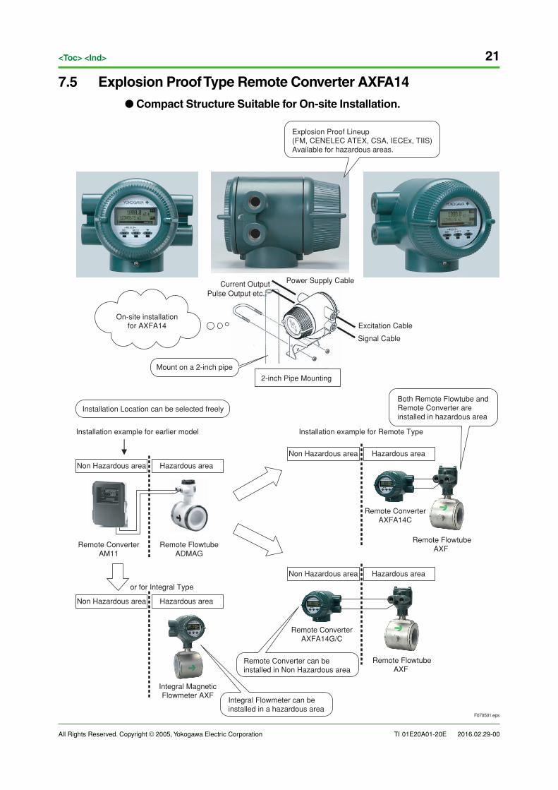
7.5 Explosion Proof Type Remote Converter AXFA14
● Compact Structure Suitable for On-site Installation.
F070501.eps
On-site installationfor AXFA14
Explosion Proof Lineup(FM, CENELEC ATEX, CSA, IECEx, TIIS)Available for hazardous areas.
Non Hazardous area
Non Hazardous area
Non Hazardous area
Non Hazardous area
Installation example for earlier model Installation example for Remote Type
Installation Location can be selected freely
Hazardous area
Hazardous area
Hazardous area
Hazardous area
Mount on a 2-inch pipe
Both Remote Flowtube andRemote Converter areinstalled in hazardous area
Remote ConverterAM11
Remote FlowtubeADMAG
Remote ConverterAXFA14C
Remote FlowtubeAXF
Integral MagneticFlowmeter AXF
Integral Flowmeter can beinstalled in a hazardous area
Remote ConverterAXFA14G/C
Remote FlowtubeAXF
Excitation Cable
Power Supply Cable
Signal Cable
2-inch Pipe Mounting
Remote Converter can beinstalled in Non Hazardous area
or for Integral Type
Current OutputPulse Output etc.
22
All Rights Reserved. Copyright © 2005, Yokogawa Electric Corporation
<Toc> <Ind>
TI 01E20A01-20E 2016.02.29-00
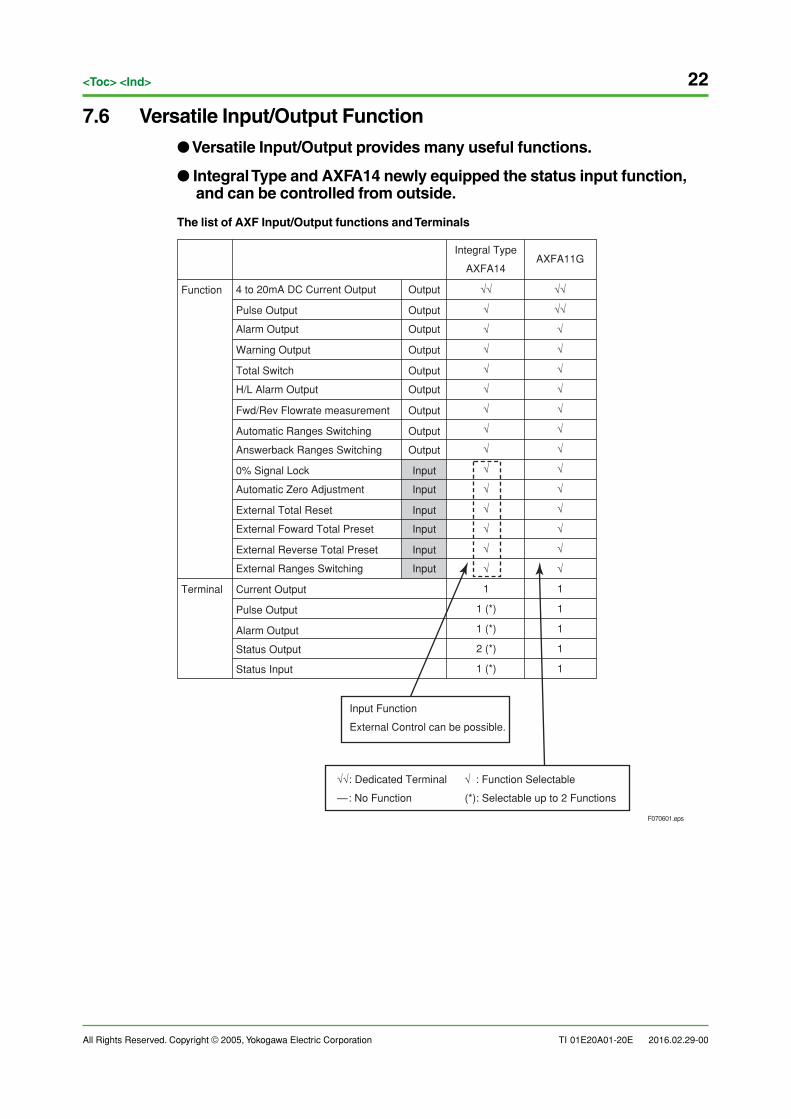
7.6 Versatile Input/Output Function
● Versatile Input/Output provides many useful functions.
● Integral Type and AXFA14 newly equipped the status input function,and can be controlled from outside.
The list of AXF Input/Output functions and Terminals
Input Function
External Control can be possible.
√√
√√
√
√
√
√
√
√
√
√
√
√
√
√
√
1
1
1
1
1
√√
√
√
√
√
√
√
√
√
√
√
√
√
√
√
1
1 (*)
1 (*)
2 (*)
1 (*)
F070601.eps
Terminal
Function
Integral Type
AXFA14AXFA11G
4 to 20mA DC Current Output
Pulse Output
Alarm Output
Warning Output
Total Switch
H/L Alarm Output
Fwd/Rev Flowrate measurement
Automatic Ranges Switching
Answerback Ranges Switching
0% Signal Lock
Automatic Zero Adjustment
External Total Reset
External Reverse Total Preset
External Ranges Switching
Current Output
Pulse Output
Alarm Output
Status Output
Status Input
External Foward Total Preset
Output
Output
Output
Output
Output
Output
Output
Output
Output
Input
Input
Input
Input
Input
Input
√√: Dedicated Terminal √ : Function Selectable
—: No Function (*): Selectable up to 2 Functions
All Rights Reserved. Copyright © 2005, Yokogawa Electric CorporationSubject to change without notice.
TI 01E20A01-20E
<Toc> <Ind>
2016.02.29-00
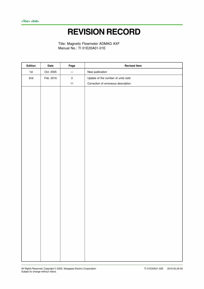
REVISION RECORDTitle: Magnetic Flowmeter ADMAG AXFManual No.: TI 01E20A01-01E
Edition Date Page Revised Item
1st Oct. 2005 — New publication
2nd Feb. 2016 3 Update of the number of units sold
11 Correction of erroneous description


![ADMAG TI Series AXW Magnetic Flowmeter [Size: 500 to 1800 ... · Safety Manual IM 01E21A21-02EN ADMAG TI Series AXW Magnetic Flowmeter [Size: 500 to 1800 mm (20 to 72 in.)] Installation](https://img.pdfslide.us/doc/110x75/5f0814b47e708231d4203d2d/admag-ti-series-axw-magnetic-flowmeter-size-500-to-1800-safety-manual-im-01e21a21-02en.jpg)


![AXFA11G Magnetic Flowmeter Remote Converter [Hardware Edition/Software Edition… · 2021. 1. 24. · ADMAG TI Series AXW Magnetic Flowmeter [Size: 500 to 1800 mm (20 to 72 in.)]](https://img.pdfslide.us/doc/110x75/60c55d286bdb095bdc297a8e/axfa11g-magnetic-flowmeter-remote-converter-hardware-editionsoftware-2021-1.jpg)


![AM012 Calibrator for Magnetic Flowmeter · AXW Magnetic Flowmeter [Size: 500 to 1800 mm (20 to 72 in.)] GS 01E25D11-01EN FSA130 ADMAG TI Verification Tool GS 01E21A04-01EN AXR Two-wire](https://img.pdfslide.us/doc/110x75/601bddf1b7f86b2db31d5c91/am012-calibrator-for-magnetic-flowmeter-axw-magnetic-flowmeter-size-500-to-1800.jpg)


![ADMAG TI Series AXW Magnetic Flowmeter BRAIN ......ADMAG TI Series AXW MagneticFlowmeter [Size: 500 to 1800 mm (20 to 72 in.)] GeneralSpecifications GS 01E25D11-01EN AXFA11G AXF Series](https://img.pdfslide.us/doc/110x75/60c5599dd936ec767712c52e/admag-ti-series-axw-magnetic-flowmeter-brain-admag-ti-series-axw-magneticflowmeter.jpg)